analizador de bomba de infusión ida4_manual_operacion
TRANSCRIPT

8/6/2019 analizador de bomba de infusión IDA4_Manual_Operacion
http://slidepdf.com/reader/full/analizador-de-bomba-de-infusion-ida4manualoperacion 1/74
IDA-4 PlusInfusion Pump
Analyzer
OperatorsManual

8/6/2019 analizador de bomba de infusión IDA4_Manual_Operacion
http://slidepdf.com/reader/full/analizador-de-bomba-de-infusion-ida4manualoperacion 2/74

8/6/2019 analizador de bomba de infusión IDA4_Manual_Operacion
http://slidepdf.com/reader/full/analizador-de-bomba-de-infusion-ida4manualoperacion 3/74
IDA-4 Plus
Infusion Pump Analyzer
Operators Manual
April 2005 2005 Fluke Corporation. All rights reserved. Printed in USAAll product names are trademarks of their respective companies.

8/6/2019 analizador de bomba de infusión IDA4_Manual_Operacion
http://slidepdf.com/reader/full/analizador-de-bomba-de-infusion-ida4manualoperacion 4/74
IDA-4 Plus
Operators Manual
ii

8/6/2019 analizador de bomba de infusión IDA4_Manual_Operacion
http://slidepdf.com/reader/full/analizador-de-bomba-de-infusion-ida4manualoperacion 5/74
Infusion Pump Analyzer
Contents
iii
ContentsContents................................................................................................................................................................iii
Notices.................................................................................................................................................................vii Customer Service and Sales ................................................................................................................................ vii All Rights Reserved............................................................................................................................................. vii Restrictions and Liabilities .................................................................................................................................. vii Claims.................................................................................................................................................................. vii Warnings ............................................................................................................................................................ viii Patient Circuit..................................................................................................................................................... viii Contamination of the Measuring System ........................................................................................................... viii Explosion Risk ................................................................................................................................................... viii Switching the Instrument ON or OFF ................................................................................................................ viii Connections........................................................................................................................................................ viii Storage and Shipping............................................................................................................................................ ix Removing Internal Water before Shipping or Storage ......................................................................................... ix Storage and Packing ............................................................................................................................................. ix
Trademarks........................................................................................................................................................... ix Manufacturing Location....................................................................................................................................... ix Warranty................................................................................................................................................................ x Warranty and Product Support ...............................................................................................................................x Warranty Disclaimer ..............................................................................................................................................x
Introduction........................................................................................................................................... 1-1 Thank you........................................................................................................................................................... 1-1 Introduction ........................................................................................................................................................ 1-1 Device Compatibility.......................................................................................................................................... 1-1 About This Manual............................................................................................................................................. 1-1 Features .............................................................................................................................................................. 1-2 Package Contents ............................................................................................................................................... 1-2 Specifications .....................................................................................................................................................1-3
Electrical Specification:...................................................................................................................................... 1-3 Flow Rate Measurement..................................................................................................................................... 1-3 Volume Measurement ........................................................................................................................................ 1-3 PCA Bolus Measurement ................................................................................................................................... 1-3 Pressure Measurement........................................................................................................................................ 1-3 Physical .............................................................................................................................................................. 1-4 Environmental .................................................................................................................................................... 1-4 Transportability .................................................................................................................................................. 1-4
An Overview .......................................................................................................................................... 2-1 Description of the Device and Intended Use ...................................................................................................... 2-1 General ............................................................................................................................................................... 2-1 Model Variations................................................................................................................................................ 2-1 Operational Modes ............................................................................................................................................. 2-1
Volume & Flow Measurement ...........................................................................................................................2-1 Occlusion & Back Pressure Measurement ......................................................................................................... 2-1 Front Panel Description...................................................................................................................................... 2-2 Front Panel Layout Drawing .............................................................................................................................. 2-3 Rear Panel Description.......................................................................................................................................2-4 Rear Panel Layout Drawing ............................................................................................................................... 2-5
8/6/2019 analizador de bomba de infusión IDA4_Manual_Operacion
http://slidepdf.com/reader/full/analizador-de-bomba-de-infusion-ida4manualoperacion 6/74
IDA-4 Plus
Operators Manual
iv
3 Operating Instructions Connecting Infusion Pumps under Test..............................................................................................................3-1 See Inlet Hose Connections and Outlet Hose Connections drawings. ............................................................... 3-1 Inlet Hose Connections Drawing........................................................................................................................3-2 Outlet Hose Connections Drawing..................................................................................................................... 3-3 General Operating Notes .................................................................................................................................... 3-4
First Time Use.................................................................................................................................................... 3-4 Report Header..................................................................................................................................................... 3-4 Set Clock ............................................................................................................................................................ 3-4 Test Parameters .................................................................................................................................................. 3-4 Printer................................................................................................................................................................. 3-4 Measuring Circuit...............................................................................................................................................3-4 Test Fluid............................................................................................................................................................ 3-4 Warning of Contamination................................................................................................................................. 3-5 Start-up Screen ................................................................................................................................................... 3-6 Status All Channels Screen ................................................................................................................................ 3-6 Utilities............................................................................................................................................................... 3-7 Recall Tests ........................................................................................................................................................3-7 Set Clock ............................................................................................................................................................ 3-7 LCD Set-up......................................................................................................................................................... 3-8
Printer Options ................................................................................................................................................... 3-8 Report Header..................................................................................................................................................... 3-9 RS232 Port ......................................................................................................................................................... 3-9 Engineering Tests ............................................................................................................................................. 3-10 Test Parameters ................................................................................................................................................ 3-10 Channel Set-up Menu.......................................................................................................................................3-11 Device Information........................................................................................................................................... 3-12 Sub Menu1 ....................................................................................................................................................... 3-13 Sub Menu2 ....................................................................................................................................................... 3-14 Flow Test Screen (Prime Mode)....................................................................................................................... 3-15 Flow Test Screen (Start Mode).........................................................................................................................3-15 Flow Test Screen (Measuring Mode) ............................................................................................................... 3-16 Flow Test Screen (End of Test Mode).............................................................................................................. 3-17 Flow Graph Screen........................................................................................................................................... 3-18 Occlusion Test Screen...................................................................................................................................... 3-19 Occlusion Test Screen (Wait Mode)................................................................................................................. 3-19 Occlusion Test Screen (Start Mode).................................................................................................................3-20 Occlusion Test Screen (Measuring Mode......................................................................................................... 3-20 Occlusion Test Screen (End of Test Mode)...................................................................................................... 3-21 Occlusion Graph Screen................................................................................................................................... 3-22 PCA Test Information Screen........................................................................................................................... 3-23 PCA Test Screen .............................................................................................................................................. 3-24 PCA Test Screen (Prime Mode) .......................................................................................................................3-24 PCA Test Screen (Start Mode) .........................................................................................................................3-25 PCA Test Screen (Measuring Mode)................................................................................................................ 3-25 PCA Test Screen (End of Test Mode) .............................................................................................................. 3-26
PCA Graph Screen ........................................................................................................................................... 3-27 PCA Bolus Trigger Methods ............................................................................................................................ 3-27 Optional PCA Trigger / Remote Call Interface ................................................................................................ 3-28 Dual Rate Test Information Screen .................................................................................................................. 3-30 Dual Rate Test Screen ......................................................................................................................................3-31 Dual Rate Test Screen (Prime Mode)............................................................................................................... 3-31 Dual Rate Test Screen (Start Mode)................................................................................................................. 3-31 Dual Rate Test Screen (Measuring Mode) ....................................................................................................... 3-32 Dual Rate Test Screen (End of Test Mode)...................................................................................................... 3-33 Dual Rate Graph Screen................................................................................................................................... 3-34 Measuring Flow-rate against Back-pressure .................................................................................................... 3-35

8/6/2019 analizador de bomba de infusión IDA4_Manual_Operacion
http://slidepdf.com/reader/full/analizador-de-bomba-de-infusion-ida4manualoperacion 7/74
Infusion Pump Analyzer
Contents
v
Suggested Apparatus for Back Pressure Testing Drawing ...............................................................................3-36
4 Maintenance, Service and Calibration User Care and Maintenance................................................................................................................................ 4-1 Storage................................................................................................................................................................ 4-1 Handling............................................................................................................................................................. 4-1 Use......................................................................................................................................................................4-1
Care of the Instrument Case ............................................................................................................................... 4-1 Cleaning the Inside of the Instrument................................................................................................................. 4-1 User Performance Check.................................................................................................................................... 4-2
A Infusion Devices Delivery Methods Infusion Devices: An Overview ........................................................................................................................A-1 Gravity Controllers............................................................................................................................................ A-1 Drip-Rate Controllers........................................................................................................................................ A-1 Volumetric Controllers...................................................................................................................................... A-1 Infusion Pumps.................................................................................................................................................. A-1 Drip-Rate Pumps ............................................................................................................................................... A-1 Volumetric Pumps............................................................................................................................................. A-1 Syringe Pumps (‘Syringe Drivers’) ................................................................................................................... A-1 Patient Controlled Analgesia (PCA) Pumps...................................................................................................... A-2
Pumps for Ambulatory Use............................................................................................................................... A-2 Anesthesia Pumps.............................................................................................................................................. A-2 Multi-Purpose Pumps........................................................................................................................................ A-2 Other Devices.................................................................................................................................................... A-2 Flow Regulators ................................................................................................................................................ A-2 Infusion Devices: A More Detailed Look.......................................................................................................... A-2 Gravity Controllers............................................................................................................................................ A-2 General .............................................................................................................................................................. A-2 Drip-Rate Controllers........................................................................................................................................ A-3 Accuracy of Drip Controlled Devices ............................................................................................................... A-3 Volumetric Controllers...................................................................................................................................... A-3 Infusion Pumps.................................................................................................................................................. A-4 General .............................................................................................................................................................. A-4
Drip - Rate Pumps ............................................................................................................................................. A-4 Volumetric Pumps............................................................................................................................................. A-4 Syringe Pumps................................................................................................................................................... A-5 PCA Pumps ....................................................................................................................................................... A-5 Pumps for Ambulatory Use............................................................................................................................... A-6 Miniature Syringe Pumps.................................................................................................................................. A-6 Miniature Volumetric Pumps ............................................................................................................................ A-6 Anesthesia Pumps.............................................................................................................................................. A-6
B Computer Control Commands Overview............................................................................................................................................................B-1 Controlling the IDA-4 Plus with HydroGraph ................................................................................................B-1 Controlling the IDA-4 Plus Using Serial Protocol .............................................................................................B-2 Command Conventions ......................................................................................................................................B-2
Perform a Flow Test [CnF,a,b,c]........................................................................................................................B-2 Perform a Volume Test [CnV,a,b,c]...................................................................................................................B-3 Perform an Occlusion Pressure Test [CnO, a,b,c] ..............................................................................................B-3 Perform a PCA Test [CnPCA,a,b,c]...................................................................................................................B-3 Perform a Dual Flow Rate Test [CnD,a,b,c,d,e,f] ..............................................................................................B-4 Fetch the Current Flow Measured on a Channel [FLOWn] ...............................................................................B-4 Fetch the Current Volume Accumulated on a Channel [VOLn] ........................................................................B-4 Fetch the Current Pressure on a Channel [PRESn].............................................................................................B-5 Fetch the Peak Pressure on a Channel [PKPRESn]............................................................................................B-5

8/6/2019 analizador de bomba de infusión IDA4_Manual_Operacion
http://slidepdf.com/reader/full/analizador-de-bomba-de-infusion-ida4manualoperacion 8/74
IDA-4 Plus
Operators Manual
vi

8/6/2019 analizador de bomba de infusión IDA4_Manual_Operacion
http://slidepdf.com/reader/full/analizador-de-bomba-de-infusion-ida4manualoperacion 9/74

8/6/2019 analizador de bomba de infusión IDA4_Manual_Operacion
http://slidepdf.com/reader/full/analizador-de-bomba-de-infusion-ida4manualoperacion 10/74
IDA-4 Plus
Operators Manual
viii
2. Pack the instrument carefully, using the original packing materials if available.
Failure to pack the instrument properly could void your warranty and result inyou paying for the instrument’s repair.
3. Insure the unit for full retail value and ship to the address specified by Fluke
WarningsPatient Circuit
This instrument has been designed for testing infusion devices but must NEVER be
used while connected to a patient.
Tubing sets utilized to test infusion devices must never be used to administer fluids to patients.
Some older style infusion devices may have reusable components that could come in
direct contact with the fluids being pumped. When testing these types of devices care
must be taken to avoid possible contamination of reusable components due to
backflow conditions.
Contamination of the Measuring System
For best results use degassed water made up with detergent, as described under ‘Test
Fluid’ on page 3-4.
High viscosity fluids cannot be used. Liquid containing oils (solvents, or strong
chemicals) may also damage or contaminate the transducer. Do not use "Bleach" type
of sterilizing agents, or alcohol’s.
To extend the life of the transducer and to maintain accuracy it is recommended that periodically 20 ml of detergent solution be introduced into the fluid inlet port, left for
30 minutes, and then flushed out with 500 ml of clean water.
Care should be taken to prevent dirt, dust, metal swarf, or other debris from entering
the measuring system since these are likely to damage the transducers.
Explosion Risk
This instrument is not to be used in the presence of flammable anesthetic gases or
vapors.
Switching the Instrument ON or OFF
As is common with most other computing equipment, this instrument may be
damaged by repeated interruption of the power supply, either by rapid switching ON
or OFF, or by removing the line cord when the instrument is energized. After
switching OFF allow at least 3 seconds before switching the unit ON. Never
disconnect the line cord without first switching the unit OFF.
The ON / OFF switch is located on the rear panel of the unit.
Connections
All external leads connecting to the IDA-4 Plus e.g. RS232 and Printer leads, must be
no longer than 2.5 meters in length.

8/6/2019 analizador de bomba de infusión IDA4_Manual_Operacion
http://slidepdf.com/reader/full/analizador-de-bomba-de-infusion-ida4manualoperacion 11/74
Infusion Pump Analyzer
Storage and Shipping
ix
Storage and Shipping
Removing Internal Water before Shipping or Storage
Before long-term storage or shipping it is recommended that all-internal water be
removed from the instrument. After manufacture and testing, internal water isremoved by connecting the FLUID OUT ports to a (medical) suction pump for 2
minutes in the unit “OFF” condition. Users may wish to employ this method, whichwill not harm the unit.
Do not use compressed air to clear out internal water since pressures greater than 310
kPa (45 psi) may damage the pressure transducer.
Storage and Packing
Remove as much internal water as possible (as described above).
Store away from sunlight.
Protect from frost (internal water may freeze and expand)
Protect from vibration and shock
The unit is a delicate electronic measuring instrument and as such should be cared for
in the appropriate manner.
The unit should not be opened unless there is a facility to confirm the function and
calibration of the unit afterwards.
There are certain types of keyboard that under ESD conditions can cease to function.
Disconnecting the keyboard and reconnecting usually restores normal keyboard
function. It is recommended a CE marked keyboard is used.
Trademarks
All trademarks mentioned in this document are acknowledged.
Manufacturing for:
Fluke Biomedical
6920 Seaway Blvd
Everett, WA 98203 USA
775-883-3400
800-648-7952

8/6/2019 analizador de bomba de infusión IDA4_Manual_Operacion
http://slidepdf.com/reader/full/analizador-de-bomba-de-infusion-ida4manualoperacion 12/74
IDA-4 Plus
Operators Manual
x
Warranty
Warranty and Product Support
Fluke Biomedical warrants this instrument against defects in materials andworkmanship for one full year from the date of original purchase. During the warranty
period, we will repair or, at our option, replace at no charge a product that proves to
be defective, provided you return the product, shipping prepaid, to Fluke Biomedical.
This warranty does not apply if the product has been damaged by accident or misuseor as the result of service or modification by other than Fluke Biomedical. IN NO
EVENT SHALL FLUKE BIOMEDICAL BE LIABLE FOR CONSEQUENTIAL
DAMAGES.
Only serialized products and their accessory items (those products and items bearinga distinct serial number tag) are covered under this one–year warranty. PHYSICAL
DAMAGE CAUSED BY MISUSE OR PHYSICAL ABUSE IS NOT COVERED
UNDER THE WARRANTY. Items such as cables and nonserialized modules are
not covered under this warranty.
Recalibration of instruments is not covered under the warranty.
This warranty gives you specific legal rights, and you may also have other rightswhich vary from state to state, province to province, or country to country. This
warranty is limited to repairing the instrument to Fluke Biomedical’s specifications.
Warranty Disclaimer
Should you elect to have your instrument serviced and/or calibrated by someone other
than Fluke Biomedical, please be advised that the original warranty covering your product becomes void when the tamper-resistant Quality Seal is removed or broken
without proper factory authorization. We strongly recommend, therefore, that you
send your instrument to Fluke Biomedical for factory service and calibration,especially during the original warranty period.
In all cases, breaking the tamper-resistant Quality Seal should be avoided at all cost,
as this seal is the key to your original instrument warranty. In the event that the seal
must be broken to gain internal access to the instrument, you must first contact Fluke
Biomedical’s Technical Assistance Department at 775-883-3400. You will berequired to provide the serial number for your instrument as well as a valid reason for
breaking the Quality Seal. You should break this seal only after you have received
factory authorization. Do not break the Quality Seal before you have contacted us.Following these steps will help ensure that you will retain the original warranty on
your instrument without interruption.

8/6/2019 analizador de bomba de infusión IDA4_Manual_Operacion
http://slidepdf.com/reader/full/analizador-de-bomba-de-infusion-ida4manualoperacion 13/74
1-1
Chapter 1
IntroductionThis chapter introduces the
instrument and describes its features.
Thank you
Thank you for purchasing this instrument. It will allow you to verify the operation of your
infusion devices providing measurements of volume delivered, flow rate and occlusion and backpressure.
Introduction
There is now a reliable way to verify the condition and performance of infusion devices
with various methods of delivery. This instrument has been provided to the medical andhealth industry so that the performance of most infusion devices currently on the market
can be determined.
Device Compatibility
The purpose of this unit is to quickly establish the state of any given infusion device and to
determine the performance qualities of the device. This instrument can test and evaluate
virtually any infusion device on the market today.
Because each infusion device manufacturer uses slightly different technology and delivery
methods vary, provisions have been made to measure all currently used methods of delivery.
About This Manual
The intent of this user's guide is to quickly instruct the new user on how to set up andoperate this instrument. To this end, we've employed certain conventions to help you read
and understand this manual.
The operation of this instrument is shown with LCD screen detail and text instructions and
description, including which particular button to press, alongside the screen.

8/6/2019 analizador de bomba de infusión IDA4_Manual_Operacion
http://slidepdf.com/reader/full/analizador-de-bomba-de-infusion-ida4manualoperacion 14/74
IDA-4 Plus
Operators Manual
1-2
Features
Tests up to four Infusion Devices simultaneously (when four measuring Transducers fitted)
Five button keypad operation
Measurement of Volume Delivered
Measurement of Flow Rate
Measurement of Occlusion Pressure
Measurement of Back Pressure
Menu driven Utilities settings
LCD (liquid crystal display) super twist Graphics with back light
Package Contents
The contents of this package as shipped include:
The main unit
Line Cord 4 x 3 way Luer stopcock.
1 x 20 ml syringe
4 x Drain tubing
2 x Fuse
Operator’s Manual
Calibration Certificate
Certificate of Conformity
Registration card

8/6/2019 analizador de bomba de infusión IDA4_Manual_Operacion
http://slidepdf.com/reader/full/analizador-de-bomba-de-infusion-ida4manualoperacion 15/74
Infusion Pump Analyzer Introduction 1
1-3
Specifications
Electrical Specification:
Supply Voltage 90 - 260 VAC.
Supply Frequency 50 - 60 Hz.
Supply Power < 30 VA.
Fuse 20 mm 250 V, 1 A (T) (slow blow).
Earth Leakage Current < 1.0 mA in single fault condition.
Flow Rate Measurement
Technique: Flow is calculated by measuring a volume over time.
Range: 0.5 - 1000 ml/hr.
Accuracy: 1% of reading ± 1 LSD for flows of 16 - 200 ml/hr for volumes over 20 ml.
Otherwise, 2% of reading ± 1LSD after delivery of 10 ml under laboratory
conditions.
Volume Measurement
Technique: Volume is measured directly by the transducer in minimum sample sizes of
60 micro-liters.
Range: 0.06 - 9999 ml.
Accuracy: 1% of reading ± 1 LSD for flows of 16 - 200 ml/hr for volumes over 20 ml.
Otherwise, 2% of reading ± 1LSD after delivery of 10 ml under laboratory
conditions.
PCA Bolus Measurement
Technique: Volume is measured directly by the transducer in minimum bolus volumes
of 0.5 ml. The measurement is made with a continuous rate between 0.0 and
30 ml/hr. The bolus flow rate should be at least four times the basal flowrate for reliable detection of boluses.
Min Bolus: 0.5 ml.
Accuracy: See volume measurement.
Pressure Measurement
Technique: Direct occlusion of the infusion line and measurement of pressure prior to
the glass transducer.
Range: 0 to 45 PSI and equivalents in mmHg and kPa.
Accuracy: 1% of Full Scale ± 1 LSD under laboratory conditions.

8/6/2019 analizador de bomba de infusión IDA4_Manual_Operacion
http://slidepdf.com/reader/full/analizador-de-bomba-de-infusion-ida4manualoperacion 16/74
IDA-4 Plus
Operators Manual
1-4
Physical
Dimensions: ~19.05 cm x 18.11 cm x 30.18 (L x W x H)
(for rear panel handle add 3.81cm)
Weight: 5.0 Kg (with 4 transducer fitted)
Case: Molded plastic front panel, metal rear housing.
Color: RAL 9002
Environmental
Operational: 15-30 C up to 50% Relative Humidity
Storage: 0-40 C at 85% RH or lessDo not leave for more than 48 hours at -20 C
Transportability
If possible use the packaging supplied by the manufacturer. If this is not possible then enclose the
instrument in a clear plastic bag, and place it in a cardboard box with plastic packing materials,
with at least 5 cm (2 inches) between the instrument and the exterior of the box to protect againstshock. Remove all water before packing.

8/6/2019 analizador de bomba de infusión IDA4_Manual_Operacion
http://slidepdf.com/reader/full/analizador-de-bomba-de-infusion-ida4manualoperacion 17/74
2-1
Chapter 2
An OverviewThis chapter gives an overview of the
instrument to help you understand the system.
Description of the Device and Intended Use
General
This is an instrument providing an automated system for measuring the Flow Rate, Volume
Delivered and Occlusion (Stall) Pressure of Infusion Devices with various methods of delivery.
It is used to verify the performance of Infusion Devices and provides facilities for
displaying results on the instrument’s LCD, saving test results for subsequent printing and /or downloading to a PC.
Model VariationsThere is one basic design which has provisions for one, two, three or four independent
channels of measuring transducers within a common housing, providing options for testing
up to four Infusion Devices simultaneously with one instrument.
Operational Modes
The unit can be used in a stand alone mode displaying results on the LCD and can
subsequently print saved test results via a printer port and / or download saved test resultsto a PC via an RS232 port.
The unit may also be linked to, controlled by and display results via a PC using an external
program, such as HydroGraph™ available from Fluke Biomedical.
Volume & Flow MeasurementVolume and flow measurements are achieved by using a calibrated burette and opto-sensors within each measurement transducer to accurately monitor the volume and time of
the meniscus passing up the burette. This data is processed to provide Average Flow Rates,
Bolus and Total Volume Delivered and Timing measurements.
Occlusion & Back Pressure Measurement
A pressure transducer within each transducer performs pressure measurement. The output
of the pressure transducer is fed to a conditioning amplifier then processed and the resultsdisplayed on the LCD and, if connected, on the PC screen. The user has the option to
display Occlusion Pressure in psi, mmHg or kPa whereas Back Pressure measurement isset to default to mmHg only.

8/6/2019 analizador de bomba de infusión IDA4_Manual_Operacion
http://slidepdf.com/reader/full/analizador-de-bomba-de-infusion-ida4manualoperacion 18/74
IDA-4 Plus
Operators Manual
2-2
Front Panel Description
1. Liquid Crystal Display-240 dot (W) x 128 (H). Graphic and Alphanumeric. With backlight.
2. Up, Down, Right and Left key-pad switches
3. Enter keypad.
4. Power ‘ON’ Indicator
5. Channel 1 Fluid ‘IN’ connector.
6. Channel 2 Fluid ‘IN’ connector.
7. Channel 3 Fluid ‘IN’ connector.
8. Channel 4 Fluid ‘IN’ connector.

8/6/2019 analizador de bomba de infusión IDA4_Manual_Operacion
http://slidepdf.com/reader/full/analizador-de-bomba-de-infusion-ida4manualoperacion 19/74
Infusion Pump Analyzer
An Overview 2
2-3
Front Panel Layout Drawing
channel 1 channel 2
inlets
channel 3 channel 4
1
2
3
4
5 6 7 8

8/6/2019 analizador de bomba de infusión IDA4_Manual_Operacion
http://slidepdf.com/reader/full/analizador-de-bomba-de-infusion-ida4manualoperacion 20/74
IDA-4 Plus
Operators Manual
2-4
Rear Panel Description
9. Mains ON / OFF switch.
10. Three pin IEC mains inlet connection.
11. Twin fuses integral with mains connector.
12. Alarm Control port. 15 way. (for optional trigger interface).
13. Parallel Printer Port. 25 way Female.Configured in the same way as a PC Printer Port.
14. Bar Code Wand Port. 9 way Female.
Configured for HP Smart Wand (2400 Baud, n, 8, 1).
15. Computer RS232 Port. 9 way Female.
Configured in the same way as PC COM Port.
16. Channel 4 Fluid ‘OUT’ connector.
17. Channel 3 Fluid ‘OUT’ connector.
18. PC AT keyboard Port.Configured for AT keyboards.
19. Channel 2 Fluid ‘OUT’ connector.
20. Channel 1 Fluid ‘OUT’ connector.
21. Carrying handle.

8/6/2019 analizador de bomba de infusión IDA4_Manual_Operacion
http://slidepdf.com/reader/full/analizador-de-bomba-de-infusion-ida4manualoperacion 21/74
Infusion Pump Analyzer
An Overview 2
2-5
Rear Panel Layout Drawing

8/6/2019 analizador de bomba de infusión IDA4_Manual_Operacion
http://slidepdf.com/reader/full/analizador-de-bomba-de-infusion-ida4manualoperacion 22/74
IDA-4 Plus
Operators Manual
2-6

8/6/2019 analizador de bomba de infusión IDA4_Manual_Operacion
http://slidepdf.com/reader/full/analizador-de-bomba-de-infusion-ida4manualoperacion 23/74
3-1
Chapter 3
Operating InstructionsThis chapter discusses and illustrates the method
of connecting units under test and the various operational modes.
Connecting Infusion Pumps under Test
See Inlet Hose Connections and Outlet Hose Connections drawings.
The Inlet Hose Connection drawing on the next page shows a method of connecting the
inlets from units under test together with a priming syringe, both connected via a 3-waytap.
This method is the only method that should be employed with this instrument.
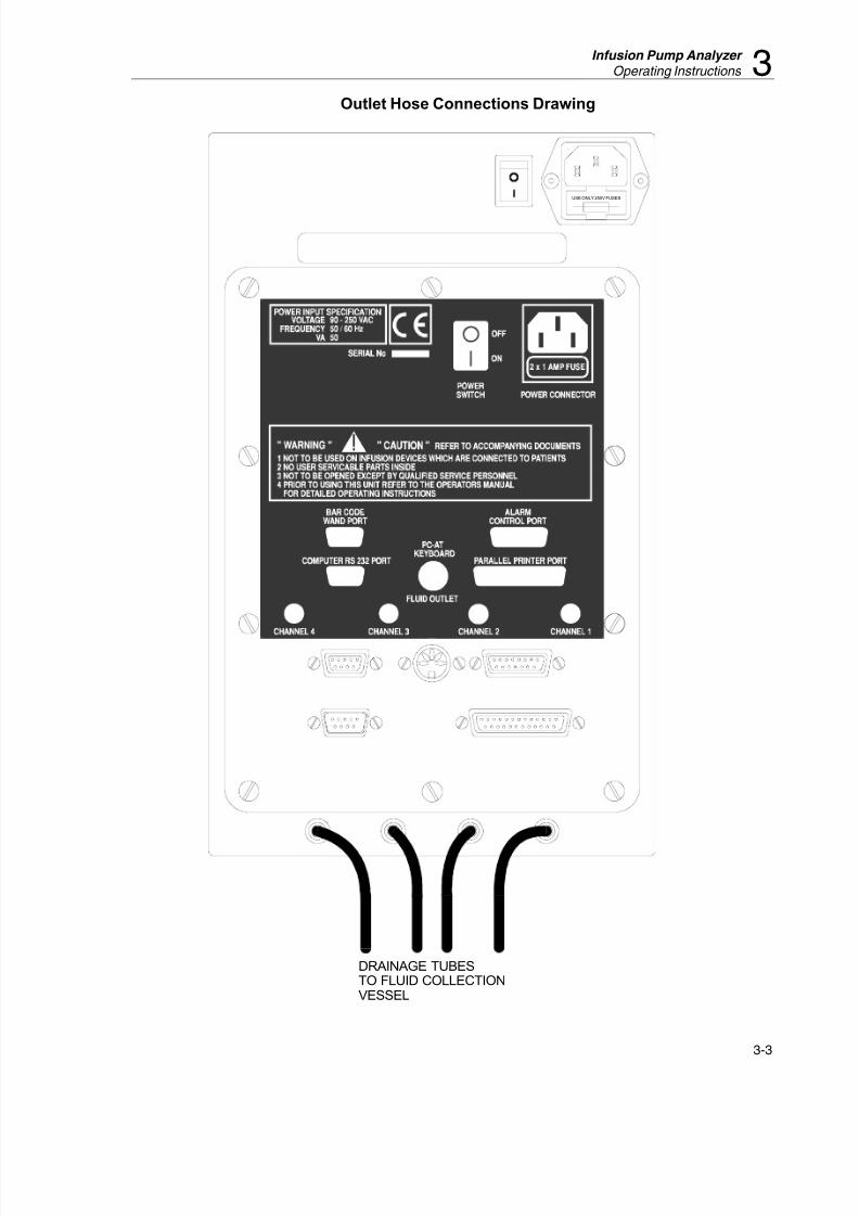
The Outlet Hose Connection drawing on page 3 shows the drain hose connections from theunit to an open drainage collection vessel. Please note that the drain Fluid Outlets shouldeach have an independent hose to the drainage vessel and should not be joined in any way.
Note: Infusion device measurement accuracy is also affected by thecompliance of the infusion device and delivery tubes. This is because
there is a momentary blockage of flow when the measurement
transducer is emptied. The back-pressure created by these events
could cause some of the flow to be diverted into the compliance of theinfusion device. For most infusion devices, the effect is trivial (less
than 0.5%), but with very soft connecting tubing and large air pockets
in the device or tubing, it could be significant. The tubing between theinfusion device and the IDA-4 Plus should therefore be fairly rigid
and all air should be removed before starting each flow test. At high
flow rates it may be desirable to increase the compliance of the inlet
tubing (longer or softer tube) if the back pressure interferes with theocclusion sensing alarms in the infusion device.

8/6/2019 analizador de bomba de infusión IDA4_Manual_Operacion
http://slidepdf.com/reader/full/analizador-de-bomba-de-infusion-ida4manualoperacion 24/74
IDA-4 Plus
Operators Manual
3-2
Inlet Hose Connections Drawing
8/6/2019 analizador de bomba de infusión IDA4_Manual_Operacion
http://slidepdf.com/reader/full/analizador-de-bomba-de-infusion-ida4manualoperacion 25/74
Infusion Pump Analyzer
Operating Instructions 3
3-3
Outlet Hose Connections Drawing
USE ONLY 250V FUSES
DRAINAGE TUBES
TO FLUID COLLECTION
VESSEL

8/6/2019 analizador de bomba de infusión IDA4_Manual_Operacion
http://slidepdf.com/reader/full/analizador-de-bomba-de-infusion-ida4manualoperacion 26/74
IDA-4 Plus
Operators Manual
3-4
General Operating Notes
The IDA-4 Plus is operated by four directional arrow buttons and an ENTER button on
the front panel. These are used to operate a sequence of menus. An optional externalkeyboard can also be used to control the instrument and enter data. Any time data is
prompted for, the bar code port is activated. The ESC key on the external keyboard will
activate the ESC option from the menu without moving it.
If there is data in a field when it is initially selected, pressing ENTER will accept that data.
When you type over the first character, any existing data will be wiped from the field and
the newly typed data will replace it. The last character typed can be deleted using the backspace key. If ESC is pressed at any time during editing, the program will back up to
the previous field or screen as appropriate.
If a data field is reached without an external keyboard, the up-arrow button on the front
panel can be used as an ESC key,
First Time Use
When first used the operator should set his or her own user preferences.
Report Header
Set these three lines to suit your requirements. Refer to the OPERATING INSTRUCTIONS
/ UTILITIES section for details.
Set Clock
Set the time & date to your time zone. The IDA-4 Plus contains a battery backed real-timeclock device to maintain time and date when the instrument is switched off. This is used to
time stamp the start of tests. It is not used to determine flow rate.
Test Parameters The preferred pressure units, Graph deviation and PCA pre-trigger time should be set.
Printer
The IDA-4 Plus prints text reports only. To ensure compatibility with most printers nospecial control codes are used. If graphical reports are required the optional PC program
HydroGraph™ is required.
Measuring Circuit
It is advisable to ensure that the fluid circuits are flushed with at least 100ml of the test
fluid before the first use.
Test Fluid
The IDA-4 Plus Infusion Device Analyzer is intended for use with de-ionized water with
added detergent. Fluids intended for use on patients, high viscosity, oily or corrosive
substances will damage the transducer system. Tap water may contain contaminates whichwill also damage the transducer.
A suitable test fluid can be made using de-ionized water with a wetting agent such asMICRO-90. It is suggested that a 1-% stock solution of “MICRO-90” be prepared in
volume using de-ionised water which may be kept up to 6 months in a closed vessel. This
solution should then be diluted 10:1 with de-ionized water for daily use. Should the water
you use cause too much foaming, then a 20:1 dilution is recommended for the dailysolution.

8/6/2019 analizador de bomba de infusión IDA4_Manual_Operacion
http://slidepdf.com/reader/full/analizador-de-bomba-de-infusion-ida4manualoperacion 27/74
Infusion Pump Analyzer
Operating Instructions 3
3-5
MICRO-90 is available from:
International Product Corp.201 Connecticut Dr.
P.O. Box 70
Burlington, NJ 08016-0070 USATel 609 386 8770
alsoInternational Product Corp.
1 Church RowChistlehurst, Kent BR7 5PG United Kingdom
Tel. 0208 467 8944
Warning of Contamination
Care should also be taken to prevent dirt, dust, metal swarf, or other debris from entering
the measuring system since these are likely damage the transducers. When shipping or transporting, it is advisable to remove all water using a suction pump and enclose the unit
in a plastic bag to prevent debris (such as polystyrene chips) entering the inlet or outlet
connections.

8/6/2019 analizador de bomba de infusión IDA4_Manual_Operacion
http://slidepdf.com/reader/full/analizador-de-bomba-de-infusion-ida4manualoperacion 28/74
IDA-4 Plus
Operators Manual
3-6
Start-up Screen
When the unit starts, an introductory screen containing
the name of the instrument, time, date and firmwareversion is displayed. After performing initialization
procedures and self tests the instrument advances to the
STATUS ALL CHANNELS screen.
Any errors detected are shown at the bottom of this
screen. Fatal errors are indicated as such and inhibit
progress. Non fatal errors give you the option to proceed.
Status All Channels Screen
This is a dynamic screen that shows the current activity
on all fitted channels. The designation SETUP indicates
a channel fitted with a transducer and ready for
operation. The upper case designation N/O indicates a
channel that either does not have a transducer fitted, or is not operational. This is the ‘home screen’; returned to
after all operations except those entered from theutilities menu.
Moving the cursor to UTIL and pressing ENTER
invokes the UTILITIES menu. Pressing the ENTER key with the cursor over SETUP invokes the
CHANNEL SETUP menu for the appropriate channel.
The units of pressure displayed on this screen are the
ones selected from the TEST PARAMETERS
SCREEN.
When the screen is first displayed the cursor defaults to
SETUP on the first operational channel. On subsequentoccurrences the cursor should be on the last channel
used. As a test progresses on an active channel the
prompt for that channel changes to reflect the status of the channel.
When this screen is displayed on subsequent occasions,
channels with operational transducers displays SETUP if they are not in use, or VIEW if a test is active. Active
channels also show figures relating to the currently
active test.
S T A T U S A L L C H A N N E L S
Ch 1 Ch 2 Ch 3 Ch 4
ml / h
T ml
psi
hhmm 00: 00 00: 00 00: 00 00: 00
UTIL SETUP SETUP SETUP SETUP
FLUKEBIOMEDICAL
IDA-4 PlusI n f u s i o n D e v i c e A n a l y z e r
V e r s i o n 2 . 0 9
S e r i a l N u m . 1 0 0 0 1
Date 00 -Jan -00 T i m e 14 : 40 : 00

8/6/2019 analizador de bomba de infusión IDA4_Manual_Operacion
http://slidepdf.com/reader/full/analizador-de-bomba-de-infusion-ida4manualoperacion 29/74
Infusion Pump Analyzer
Operating Instructions 3
3-7
Utilities
This screen is displayed whenever UTIL is selected.
Using the arrow keys to move the cursor to the required
utility, in this case RECALL TESTS is selected, press
ENTER and the set-up screen for the chosen utility is
displayed.
Choosing ESC and pressing ENTER will default to the
STATUS ALL CHANNELS screen.
Recall Tests
The cursor is moved by pressing the up and down buttons. When the required stored test is selected,
pressing ENTER brings up the menu selections shown
at the bottom of the screen. User’s then have the optionsto PRINT text data, DEL or ESC and return to
UTILITIES main screen.
Note: If you select DEL and press ENTER a warning
screen is displayed as shown. Selecting YES and pressing ENTER will DELETE ALL results. Makesure you have printed or downloaded any records that
you need. Selecting NO returns to the UTILITIES
menu.
Set Clock
To Set the Clock use the left and right keys to select the
item to be changed then the up and down keys to
change to the required setting.
When correct settings are achieved press ENTER to
accept these settings.
These settings cannot be altered once a test is in
progress.
U T I L I T I E S
RECALL TESTS REPORT HEADER
SET CLOCK RS232 PORT
LCD SETUP ENG TESTS
PRINTER TEST PARAMETERS
ESC
R e c a l l T e s t s
Control No Date Time
Dual Flow 03-Sep-03 14:31
Dual Flow 04-Sep-03 12:05
PCA Test 12 06-Sep-03 10:45
PRINT DELETE ESC
S e t C l o c k
Date 00–Jan –00 T i m e 09 : 57 : 25
Use th e l e f t an d r i g h t a r r o wkeys to se l ec t .
Use the up and down arrowkeys to change.
P r ess E NT E R to Accep t
WARNING
T h i s w i l l d e l e t e A L L r e s u l t s !
A r e y o u s u r e ?
NO YES
8/6/2019 analizador de bomba de infusión IDA4_Manual_Operacion
http://slidepdf.com/reader/full/analizador-de-bomba-de-infusion-ida4manualoperacion 30/74
IDA-4 Plus
Operators Manual
3-8
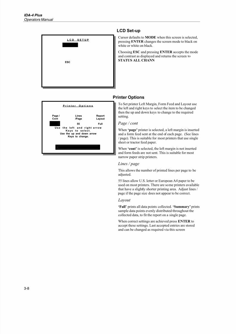
LCD Set-up
Cursor defaults to MODE when this screen is selected,
pressing ENTER changes the screen mode to black onwhite or white on black.
Choosing ESC and pressing ENTER accepts the mode
and contrast as displayed and returns the screen to
STATUS ALL CHANN
Printer Options
To Set printer Left Margin, Form Feed and Layout use
the left and right keys to select the item to be changed
then the up and down keys to change to the required
setting.
Page / cont
When ‘page’ printer is selected, a left margin is inserted
and a form feed sent at the end of each page. (See lines
/ page). This is suitable for most printers that use singlesheet or tractor feed paper.
When ‘cont’ is selected, the left margin is not inserted
and form feeds are not sent. This is suitable for most
narrow paper strip printers.
Lines / page
This allows the number of printed lines per page to be
adjusted.55 lines allow U.S. letter or European A4 paper to be
used on most printers. There are some printers available
that have a slightly shorter printing area. Adjust lines /
page if the page size does not appear to be correct.
Layout
‘Full’ prints all data points collected. ‘Summary’ prints
sample data points evenly distributed throughout the
collected data, to fit the report on a single page.
When correct settings are achieved press ENTER to
accept these settings. Last accepted entries are stored
and can be changed as required via this screen
L C D S E T U P
M O DE
ESC
P r i n t e r O p t i o n s
Page /Cont Lines /Page ReportLayout
Page 55 Full
Use th e l e f t an d r i g h t a r r o wKeys to se l ec t .
Use the up and down arrowKeys to change.
P r ess E NT E R to Accep t

8/6/2019 analizador de bomba de infusión IDA4_Manual_Operacion
http://slidepdf.com/reader/full/analizador-de-bomba-de-infusion-ida4manualoperacion 31/74
Infusion Pump Analyzer
Operating Instructions 3
3-9
Report Header
The REPORT HEADER of three lines and up to 28
characters on each line is entered via this screen. Theentry is stored and will appear on all printouts, it should
also be noted that this header can not be changed once a
test is in progress. Entry is made via the alphanumeric
matrix using the 5 button keypad, a bar code reader or if connected, via an external keyboard. On subsequent
selection of this screen the existing stored entry is
shown. This is stored in non-volatile memory andretained when the instrument is switched off.
To use the alphanumeric matrix, use the direction keys
to move the cursor to the desired character, and select
by pressing the ENTER key.
Continue until header is complete.
Moving the cursor to any OK position accepts the text,
and move to the next field or screen. Selecting DEL deletes a character, and the ESC character escapes back
to the previous field or screen
RS232 Port
To set the RS232 protocol, use the left and right keys to
select the item to be changed then the up and down keys
to change to the required setting.
The options are:
Speed: 150 - 38400 Baud
Parity: ODD - EVEN – NONE
Data: 7 or 8 bits
Stop: 1or 2 bits
When correct settings are achieved press ENTER toaccept these settings which are stored until nextchanged via this screen.
U t i l i t y R e p o r t H e a d e r
………………………………………………………………..
………………………………………………………………..
………………………………………………………………..
O K 0 1 2 3 4 5 6 7 8 9 D E L
O K A B C D E F G H I J
O K K L M N O P Q R S T E S C
O K U V W X Y Z . , / - O K
R S 2 3 2 P O R T
S p e e d P a r i t y D a t a S t o p
1 9 2 0 0 N O N E 8 1
Use th e l e f t an d r i g h t a r r o wKeys to se l ec t .
Use th e u p an d d o w n a r r o wKeys to change.
P r ess E NT E R to Accep t

8/6/2019 analizador de bomba de infusión IDA4_Manual_Operacion
http://slidepdf.com/reader/full/analizador-de-bomba-de-infusion-ida4manualoperacion 32/74
IDA-4 Plus
Operators Manual
3-10
Engineering Tests
Using the arrow keys, move the cursor to the required
selection and press ENTER .
Test Printer
Checks the link to the printer by sending the serial
number, software version and the three lines of reportheader to the printer.
Print Settings
Prints the calibration factors for each transducer fitted.
Test Trig Box
When entered, 2 rows of 4 zero’s are displayed. The top
row monitors the trigger buttons on the PCA Trigger /
Remote Call Interface. The bottom row monitors theremote call inputs on the PCA Trigger / Remote Call
Interface. When any of these are triggered, the
appropriate ‘0’ will change to a ‘1’. The left most digitrepresents channel 1 and the right most digit channel 4.
Choosing ESC and pressing ENTER will default to the
UTILITIES Menu screen.
Test Parameters
Pressure Units
To cycle the pressure units between mmHg, kPa and
psi, use the up and down keys to change then pressENTER to accept. The chosen units of pressure
measurement are stored thereafter (until changed via
this screen) and appear on all screens where pressure isindicated except on screens where back-pressure is
indicated. This is displayed in mmHg for reasons of
high resolution.
Graph Deviation
This sets the upper and lower flow rate deviation lineson the graphs for Flow Rate and Dual Flow. If this is set
to 0 (Zero) then a single line will be displayed at the set
flow rate. If a flow rate is not entered when a test is set-
up then no deviation lines will be displayed.
PCA Pre Trig Time
When performing Lockout Time tests with PCA pumps,
this sets the time prior to the expiry of the Lock-outtime that the IDA-4 Plus will start attempting to trigger
the pump.
E N G I N E E R I N G T E S T S
T es t P r i n te r
P r i n t S e t t i n g s
T es t T r i g Bo x
ESC
T E S T P A R A M E T E R S
PCA
PressureUnits
GraphDeviation
Pre TrigTime
psi 10% 200 sec
Use the up and down arrowKeys to change.
P r ess E NT E R to Accep t

8/6/2019 analizador de bomba de infusión IDA4_Manual_Operacion
http://slidepdf.com/reader/full/analizador-de-bomba-de-infusion-ida4manualoperacion 33/74
Infusion Pump Analyzer
Operating Instructions 3
3-11
Channel Set-up Menu
This screen allows the operator to select the type of test
to be performed as a rapid test or elect to enter further details before selecting the type of test. The layout of
options on this menu has been optimized to reduce the
number of key presses when using the rapid test
options.
Using the arrow keys, move the cursors to the required
selection and press ENTER to advance to the selectedsub menu.
The following menu options are available:
Occlusion
This advances to the OCCLUSION TEST screen
where the operator will be prompted through the
occlusion test. It will not be possible to save the testresults.
Flow
This advances to the FLOW TEST screen where theoperator will be guided through Flow tests. It will not
be possible to save the test results.
Dual Flow
This advances to the DUAL FLOW INFORMATION
screen, even for a rapid test as some information isrequired to perform this test. It will not be possible to
save the test results.
Dev Info
This advances to the DEVICE INFORMATION screen where information about the device being tested
will be requested. If test results are to be saved, thisoption must be selected.
PCA
This advances to the PCA TEST INFORMATION
screen to request information required to perform aPCA test. It will not be possible to save the test results.
ESC
This returns the operator to the STATUS ALL
CHANNELS screen. The ESC key on an external
keyboard will have the same effect.
C H A N N E L 1 S E T U P
OCCLUSION DEV INFO
FLOW PCA
DUAL FLOW ESC
8/6/2019 analizador de bomba de infusión IDA4_Manual_Operacion
http://slidepdf.com/reader/full/analizador-de-bomba-de-infusion-ida4manualoperacion 34/74
IDA-4 Plus
Operators Manual
3-12
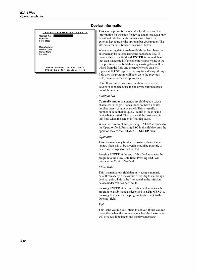
Device Information
This screen prompts the operator for device and test
information for the specific device under test. Data may be entered into the fields on this screen from the
external keyboard or the optional bar code reader. The
attributes for each field are described below.
When entering data into these fields the last character
entered may be deleted using the backspace key. If
there is data in the field and ENTER is pressed thenthat data is accepted. If the operator starts typing at the
first position in the field then any existing data will be
wiped from the field and the newly typed data will
replace it. If ESC is pressed at any time during editing a
field then the program will back up to the previousfield, menu or screen as appropriate.
Note: If you enter this screen without an external
keyboard connected, use the up arrow button to back out of the screen.
Control NoControl Number is a mandatory field up to sixteen
characters in length. If a test does not have a control
number then it cannot be saved. This is usually anumber or code that uniquely identifies the infusion
device being tested. The cursor will be positioned in
this field when the screen is first displayed.
When field is completed, pressing ENTER advances tothe Operator field. Pressing ESC in this field returns the
operator back to the CHANNEL SETUP menu.
Operator
This is a mandatory field, up to sixteen characters in
length. If a test is to be saved it should be possible todetermine who performed the test.
Pressing ENTER at the end of this field advances the
program to the Flow Rate field. Pressing ESC willreturn to the Control No field.
Flow Rate
This is a mandatory field that only accepts numeric
data. It can accept a maximum of six digits including a
decimal point. This is the flow rate that the infusion
device under test has been set to.
Pressing ENTER at the end of this field advances the
program to a sub-menu as described in SUB MENU 1.
Pressing ESC causes the program to step back to theOperator field.
Vol
This is the volume you intend to deliver. If this volumeis set, then when the volume is reached the instrument
will give two long beeps and display a message.
D e v i c e I n f o r m a t i o n C h a n 1
Control NoOperator Flow Rate
Manufacturer
Device TypeSerial Num.Location
P r ess E NT E R fo r n ex t f i e l dP r ess E S C fo r p r ev i o u s f i e l d
8/6/2019 analizador de bomba de infusión IDA4_Manual_Operacion
http://slidepdf.com/reader/full/analizador-de-bomba-de-infusion-ida4manualoperacion 35/74
Infusion Pump Analyzer
Operating Instructions 3
3-13
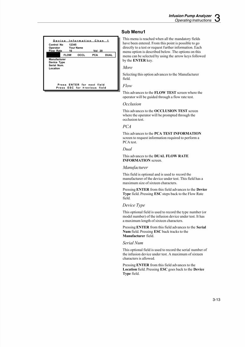
Sub Menu1
This menu is reached when all the mandatory fields
have been entered. From this point is possible to godirectly to a test or request further information. Each
menu option is described below. The options on this
menu can be selected by using the arrow keys followed
by the ENTER key.
More
Selecting this option advances to the Manufacturer
field.
Flow
This advances to the FLOW TEST screen where the
operator will be guided through a flow rate test.
Occlusion
This advances to the OCCLUSION TEST screenwhere the operator will be prompted through the
occlusion test.
PCA
This advances to the PCA TEST INFORMATION
screen to request information required to perform a
PCA test.
Dual
This advances to the DUAL FLOW RATE
INFORMATION screen.
Manufacturer
This field is optional and is used to record themanufacturer of the device under test. This field has a
maximum size of sixteen characters.
Pressing ENTER from this field advances to the Device
Type field. Pressing ESC steps back to the Flow Rate
field.
Device Type
This optional field is used to record the type number (or
model number) of the infusion device under test. It has
a maximum length of sixteen characters.
Pressing ENTER from this field advances to the Serial
Num field. Pressing ESC back tracks to the
Manufacturer field.
Serial NumThis optional field is used to record the serial number of
the infusion device under test. A maximum of sixteencharacters is allowed.
Pressing ENTER from this field advances to the
Location field. Pressing ESC goes back to the Device
Type field.
D e v i c e I n f o r m a t i o n C h a n 1
Control No 12345Operator Your NameFlow Rate 10 Vol 20
MORE FLOW OCCL PCA DUAL
Manufacturer Device TypeSerial Num.Location
P r ess E NT E R fo r n ex t f i e l dP r ess E S C fo r r ev i o u s f i e l d

8/6/2019 analizador de bomba de infusión IDA4_Manual_Operacion
http://slidepdf.com/reader/full/analizador-de-bomba-de-infusion-ida4manualoperacion 36/74
IDA-4 Plus
Operators Manual
3-14
Location
This is an optional field of sixteen characters in length.
It is used to store the normal location of the device
under test.
Pressing ENTER from this field advances to the SUB
MENU 2. ESC goes back to the Serial Number field
Sub Menu2
This menu allows you to select the type of test to
perform after you have entered all the information about
the device being tested.
ESC
This back tracks to the Location field. This gives the
operator a chance to correct any of the preceding
information that may have been entered incorrectly.
Flow
This advances to the FLOW TEST screen where the
operator will be guided through a flow rate test.Occlusion
This advances to the OCCLUSION TEST screen
where the operator is prompted through the occlusion
test.
PCA
This advances to the PCA TEST INFORMATION
screen to request information required to perform aPCA test.
Dual
This advances to the DUAL FLOW RATE
INFORMATION screen.
D e v i c e I n f o r m a t i o n C h a n 1
Control No 12345Operator Your NameFlow Rate 10 Vol 20
Manufacturer Device TypeSerial Num.Location
ESC FLOW OCCL PCA DUAL
P r ess E NT E R fo r n ex t f i e l dP r ess E S C fo r p r ev i o u s f i e l d

8/6/2019 analizador de bomba de infusión IDA4_Manual_Operacion
http://slidepdf.com/reader/full/analizador-de-bomba-de-infusion-ida4manualoperacion 37/74
Infusion Pump Analyzer
Operating Instructions 3
3-15
Flow Test Screen (Prime Mode)
This is the screen that allows the operator to control the
flow test. It has a menu across the bottom of the screenthat changes to reflect the progress of the active test.
When this screen is first displayed the operator will be
prompted to prime the channel. This is essential to
ensure the measuring circuit is filled with fluid.
Prime
This prompt stays on the screen while there is any air inthe measuring circuit. Pressing ENTER while the
prompt displays PRIME will not have any effect. As
the circuit is primed, the prompt will change to
START. There may be some flickering between
PRIME and START as bubbles are pushed through thesystem.
Status
This option takes you back to the main status screen.
You may need to do this if you need to set-up more thanone channel.
ESC
Selecting ESC or pressing the ESC key on the external
keyboard will take the operator back to the CHANNEL
SETUP menu.
Flow Test Screen (Start Mode)
Auto-Start
Pressing ENTER on this option puts the IDA-4 Plus
into AutoSTART mode. The prompt will flash until theinstrument detects that the fluid is flowing, then start
the test.Start
To manually start the test, move to the START
selection and press ENTER . The IDA-4 Plus willimmediately start analyzing the fluid flow once this is
done.
Status
This will invoke the STATUS ALL CHANNELS
screen.
ESC
Selecting ESC or pressing the ESC key on the external
keyboard will take the operator back to the CHANNELSETUP menu.
CHANNEL 1 FLOW
FLOW 0.00 Avgml /h
VOLUME 0.00 ml
ELAPSED TIME 00: 00: 00
INST. FLOW 0. 00 ml /h
BACK PRESSURE 0 mmHg
PRIME STATUS ESC
CHANNEL 1 FLOW
FLOW 0.00 Avgml /h
VOLUME 0.00 ml
ELAPSED TIME 00: 00: 00
INST. FLOW 0. 00 ml /h
BACK PRESSURE 0 mmHg
AutoSTART START STATUS ESC

8/6/2019 analizador de bomba de infusión IDA4_Manual_Operacion
http://slidepdf.com/reader/full/analizador-de-bomba-de-infusion-ida4manualoperacion 38/74
IDA-4 Plus
Operators Manual
3-16
Flow Test Screen (Measuring Mode)
When the flow test is started the screen is advanced to
the measuring mode as shown. This enables more menuoptions.
Status
This invokes the STATUS ALL CHANNELS screen.
Graph
This switches to the FLOW GRAPH screen for thecurrent channel.
Flow
This ends the current test, clears the values from the
screen and proceeds to the FLOW TEST screen in
either PRIME or START mode, depending on thecurrent state of the transducer. The results of the
subsequent test will be appended to those of the testterminated by this option.
Occlusion
This ends the current test, clears the values from the
screen and proceeds to the OCCLUSION TEST screen
in Wait Mode. The results of the subsequent test will be
appended to those of the test terminated by this option.
End
Ends the test, or sequence of tests, and advances the
FLOW TEST screen to the End of Test Mode.
CHANNEL 1 FLOW
FLOW 0.00 Avgml /h
VOLUME 0.00 ml
ELAPSED TIME 00: 00: 00
INST. FLOW 0. 00 ml /h
BACK PRESSURE 0 mmHg
STATUS GRAPH FLOW OCCL END

8/6/2019 analizador de bomba de infusión IDA4_Manual_Operacion
http://slidepdf.com/reader/full/analizador-de-bomba-de-infusion-ida4manualoperacion 39/74
Infusion Pump Analyzer
Operating Instructions 3
3-17
Flow Test Screen (End of Test Mode)
This view of the FLOW TEST screen allows the
operator to save, print or delete the results of the test.
Save
This saves the results of the flow test, or series of tests,
to non-volatile memory for later printing or transfer to acomputer via the RS232 port.
Save & Print
This saves the results as described above, then sends a
report to a printer connected to the printer port on theinstrument. The report will be in either full or summary
format, as previously selected by the operator from the
UTILITIES / PRINTER menu.
This sends a report to a printer connected to the printer port on the instrument. The report will be in either full
or summary format, as previously selected by the
operator from the UTILITIES / PRINTER menu.
Graph
This switches to the FLOW GRAPH screen for the
current channel to allow a graph of the results to beviewed before they are saved or printed.
Status
This switches to the STATUS ALL CHANNELS screen to allow the operator to use another channel or
change settings via the UTILITIES menu.
Delete
This deletes the current set of results from theoperational memory of the instrument, without savingto the non-volatile memory. CAUTION: Once this
option has been invoked there will not be any way to
recover, view or print the results of this test.
CHANNEL 1
FLOW 0.00Avgml /h
VOLUME 0.00 ml
ELAPSED TIME 00: 00: 00
SAVE SAVE & PRINT PRINT
GRAPH STATUS DELETE

8/6/2019 analizador de bomba de infusión IDA4_Manual_Operacion
http://slidepdf.com/reader/full/analizador-de-bomba-de-infusion-ida4manualoperacion 40/74

8/6/2019 analizador de bomba de infusión IDA4_Manual_Operacion
http://slidepdf.com/reader/full/analizador-de-bomba-de-infusion-ida4manualoperacion 41/74
Infusion Pump Analyzer
Operating Instructions 3
3-19
Occlusion Test Screen
This is the screen that allows the operator to control the
occlusion test. It has a menu across the bottom of thescreen that changes to reflect the progress of the test. It
is not necessary to prime the transducer to perform an
occlusion test.
The operator sets the units of pressure displayed on this
screen from the TEST PARAMETERS SCREEN.
Occlusion Test Screen (Wait Mode)
When the OCCLUSION TEST screen is first entered it
puts the transducer into a Tare measuring mode (i.e.
subtracts the ambient pressure). While the transducer isin this mode the WAIT prompt is displayed.
Wait
This menu option is never active, it informs the operator
to wait until the transducer has taken a tare reading.When the tare reading has completed this, the menu
option changes to START, and the instrument advancesto the start mode. The pump should be stopped or running very slowly during the wait period.
Status
This invokes the STATUS ALL CHANNELS screen.
ESC
Selecting ESC or pressing the ESC key on the external
keyboard takes the operator back to the CHANNEL
SETUP menu.
CHANNE L 1 O CCL US I O N
0.00 PRESSUREpsi
TIME 00 : 00 : 00Peak Pressure psi
Time of Peak 00: 00: 00
WAIT STATUS ESC

8/6/2019 analizador de bomba de infusión IDA4_Manual_Operacion
http://slidepdf.com/reader/full/analizador-de-bomba-de-infusion-ida4manualoperacion 42/74
IDA-4 Plus
Operators Manual
3-20
Occlusion Test Screen (Start Mode)
When the transducer has completed its tare operation
the screen changes as shown.
Start
When the transducer has completed its tare
measurement the START option is enabled. PressingENTER while this option is selected will start the
occlusion test and advances to the measuring mode.
Status
This invokes the STATUS ALL CHANNELS screen.
ESC
Selecting ESC or pressing the ESC key on the externalkeyboard will take the operator back to the CHANNEL
SETUP menu.
Occlusion Test Screen (Measuring Mode
When the test is started the screen enters the measuringmode as shown. This enables further menu options.
Status
This invokes the STATUS ALL CHANNELS screen.
Graph
This switches to the OCCLUSION GRAPH screen for
the current channel.
Flow
This ends the current test, clears the values from thescreen and proceeds to the FLOW TEST screen in
either PRIME or START mode, depending on the
current state of the transducer. The results of thesubsequent test will be appended to those of the test
terminated by this option.
Occlusion
This ends the current test, clears the values from thescreen and proceeds to the OCCLUSION TEST screen
in Wait Mode. The results of the subsequent test will be
appended to those of the test terminated by this option.
End
Ends the test, or sequence of tests, and advances the
OCCLUSION TEST screen to the End of Test Mode.
CHANNE L 1 O CCL US I O N
0.00 PRESSUREpsi
TIME 00 : 00 : 00Peak Pressure psi
Time of Peak 00: 00: 00
START STATUS ESC
CHANNE L 1 O CCL US I O N
0.00 PRESSUREpsi
TIME 00 : 00 : 00Peak Pressure psi
Time of Peak 00: 00: 00
STATUS GRAPH FLOW OCCL END

8/6/2019 analizador de bomba de infusión IDA4_Manual_Operacion
http://slidepdf.com/reader/full/analizador-de-bomba-de-infusion-ida4manualoperacion 43/74
Infusion Pump Analyzer
Operating Instructions 3
3-21
Occlusion Test Screen (End of Test Mode)
This view of the OCCLUSION TEST screen allows
the operator to save, print or delete the results of theocclusion test.
Save
This saves the results of the occlusion test, or the seriesof tests, to non-volatile memory for later printing or transfer to a computer via the RS232 port.
Save & Print
This saves the results as described above, then sends areport to a printer connected to the printer port on the
instrument. The report will be in either full or summary
format, as previously selected by the operator from theUTILITIES / PRINTER menu.
This sends a report to a printer connected to the printer
port on the instrument. The report will be in either full
or summary format, as previously selected by the
operator from the UTILITIES / PRINTER menu.
Status
This switches to the STATUS ALL CHANNELS screen to allow the operator to use another channel or
change settings via the UTILITIES menu.
Graph
This switches to the OCCLUSION GRAPH screen for
the current channel.
Delete
This deletes the current set of results from memorywithout saving to non-volatile memory. CAUTION: Once this option has been invoked there will not be any
way to recover, view or print the results of this test.
CHANNE L 1 O CCL US I O N
P eak P r essu r e 0 . 00 p s i
Time of Peak 00: 00: 00
Total Test Time 00: 00: 00
Set Flow Rate ml /h
SAVE SAVE & PRINT PRINT
GRAPH STATUS DELETE

8/6/2019 analizador de bomba de infusión IDA4_Manual_Operacion
http://slidepdf.com/reader/full/analizador-de-bomba-de-infusion-ida4manualoperacion 44/74
IDA-4 Plus
Operators Manual
3-22
Occlusion Graph Screen
This graph displays the pressure value over time. It
automatically adjusts its scale so that its maximum pressure and time are always within the axes.
The numerical data displayed at the right of the graph
will include the current pressure and elapsed time.Below this will be the peak pressure reached and the
time that the peak was reached.
The pressure units are those selected from the TEST
PARAMETERS SCREEN.
Status
This switches to the STATUS ALL CHANNELS screen to allow the operator to use another channel or
change settings via the UTILITIES menu.
View
This returns to the OCCLUSION TEST screen in
either the Measuring Mode or the End of Test Mode,
depending on which mode called this screen.
10psi
CHANNE L 1 O CCL US I O N
Inst.9. 05psi
00: 02: 19
Peak0. 39psi
00: 02: 19
STATUS VIEW

8/6/2019 analizador de bomba de infusión IDA4_Manual_Operacion
http://slidepdf.com/reader/full/analizador-de-bomba-de-infusion-ida4manualoperacion 45/74
Infusion Pump Analyzer
Operating Instructions 3
3-23
PCA Test Information Screen
This screen is displayed whenever the operator elects to
perform a PCA TEST.
Basal Flow Rate
This is a field must be completed to help the flow rate
discriminate algorithms within the PCA analysisroutines. If a flow rate has been entered on theDEVICE INFORMATION screen, then it will be
displayed in this field. It can be accepted by pressing
ENTER or it may be changed at this point, which willalso change the Flow Rate.
Pressing ENTER at the end of this field advances the
program to the Total Volume field. Pressing ESC willreturn to the Channel Set-up Menu.
Total Volume
This is the total volume to be infused during the test, asset on the PCA pump. When this volume has been
delivered, two long beeps will be sounded and amessage displayed.
Pressing ENTER at the end of this field advances the
program to the Bolus Volume field. Pressing ESC will
step back to the Basal Flow Rate field.
Bolus Volume
This is the bolus volume that the pump is set to deliver.
This value is recorded for information purposes only.
Pressing ENTER in this field advances the program tothe Lockout Time (minutes) field. Pressing ESC will
step back to the Total Volume field.
Lockout Time (minutes)This field and the Lockout Time (seconds) field set the
time the device under test should inhibit requests for a bolus after the last bolus was delivered.
Lockout Time (seconds)
This field is used in conjunction with the Lockout
Time (minutes) field as described above.
Pressing ENTER in this filed advances the program to
the Loading Dose field. Pressing ESC will step back tothe Lockout Time (minutes) field. Lockout time is the
time that the PCA pump is programmed to inhibit patient demands between boluses. This is used in
combination with Pre Trigger Time, as set in the TESTPARAMETERS SCREEN to attempt to trigger the
PCA pump.
Loading Dose
This is the volume expected to be delivered as the pumpstarts. It appears to the instrument as a bolus. If a non-
zero value has been entered, and the first fluid detected
is determined to be at a bolus flow rate, then the first
C h a n 1 P C A T e s t I n f o r m a t i o n
Basa l F l o w Ra te
(Co n t i n u o u s ) m l / h
T o ta l V o l u m e m l
Bo l u s V o l u m e 0 . 00 m l
L o cko u t T i m e M i n sec
L o ad i n g Do se m l
0 1 2 3 4 5 6 7 8 9 . OK
ESC DEL
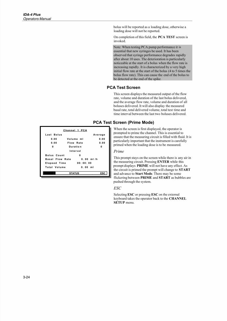
8/6/2019 analizador de bomba de infusión IDA4_Manual_Operacion
http://slidepdf.com/reader/full/analizador-de-bomba-de-infusion-ida4manualoperacion 46/74
IDA-4 Plus
Operators Manual
3-24
bolus will be reported as a loading dose, otherwise a
loading dose will not be reported.
On completion of this field, the PCA TEST screen is
invoked.
Note: When testing PCA pump performance it is
essential that new syringes be used. It has been
observed that syringe performance degrades rapidlyafter about 10 uses. The deterioration is particularlynoticeable at the start of a bolus when the flow rate is
increasing rapidly. It is characterized by a very high
initial flow rate at the start of the bolus (4 to 5 times the bolus flow rate). This can cause the end of the bolus to
be detected at the end of the spike.
PCA Test Screen
This screen displays the measured output of the flow
rate, volume and duration of the last bolus delivered,
and the average flow rate, volume and duration of all boluses delivered. It will also display the measured
basal rate, total delivered volume, total test time and
time interval between the last two boluses delivered.
PCA Test Screen (Prime Mode)
When the screen is first displayed, the operator is
prompted to prime the channel. This is essential to
ensure that the measuring circuit is filled with fluid. It is particularly important that the instrument is carefully
primed when the loading dose is to be measured.
Prime
This prompt stays on the screen while there is any air inthe measuring circuit. Pressing ENTER while this
prompt displays PRIME will not have any effect. As
the circuit is primed the prompt will change to START and advance to Start Mode. There may be some
flickering between PRIME and START as bubbles are
pushed through the system.
ESC
Selecting ESC or pressing ESC on the external
keyboard takes the operator back to the CHANNEL
SETUP menu.
Ch an n e l 1 P CA
L as t Bo l u s Aver ag e
0 . 00 V o l u m e m l 0 . 00
0 . 00 F l o w Ra te 0 . 00
0 Durat io n 0
I n te r va l
Bo l u s Co u n t 0
Basa l F l o w Ra te 0 . 00 m l / h
E l ap sed T i m e 00 : 00 : 00
T o ta l V o l u m e 0 . 00 m l
PRIME STATUS ESC

8/6/2019 analizador de bomba de infusión IDA4_Manual_Operacion
http://slidepdf.com/reader/full/analizador-de-bomba-de-infusion-ida4manualoperacion 47/74
Infusion Pump Analyzer
Operating Instructions 3
3-25
PCA Test Screen (Start Mode)
When the measuring circuit is primed successfully the
screen changes as shown.
Auto-Start
Pressing ENTER on this option puts the IDA-4 Plus
into AutoSTART mode. The prompt will flash until theinstrument detects that the fluid is flowing, then startthe test.
Start
When the measuring circuit is primed successfully thescreen changes as shown. The following menu options
are available:
ESC
Selecting ESC or pressing the ESC key on the external
keyboard takes the operator back to the CHANNEL
SETUP menu.
PCA Test Screen (Measuring Mode)
When the PCA TEST is started the screen entersmeasuring mode as shown. This enables further menu
options.
Status
This takes the operator to the STATUS ALL
CHANNELS screen.
Graph
This selection displays the PCA GRAPH screen to
view the bolus delivery verses time graph.
Bolus / Trig
This triggers a PCA Bolus request to the pump if the
pump can be triggered electrically. This requires the
PCA Trigger / Remote Call Interface. If the pump
does not have an electrical trigger (e.g. pneumatic) then
this button may be pressed simultaneously with the patient button on the pump to allow the request for
bolus to be recorded.
End
This ends the test and advance to the End of Test Mode.
Ch an n e l 1 P CA
L as t Bo l u s Aver ag e
0 . 00 V o l u m e m l 0 . 00
0 . 00 F l o w Ra te 0 . 00
0 Durat io n 0
I n te r va l
Bo l u s Co u n t 0
Basa l F l o w Ra te 0 . 00 m l / h
E l ap sed T i m e 00 : 00 : 00
T o ta l V o l u m e 0 . 00 m l
AutoSTART START STATUS ESC
Ch an n e l 1 P CA
L as t Bo l u s Aver ag e
0 . 00 V o l u m e m l 0 . 00
0 . 00 F l o w Ra te 0 . 00
0 Durat io n 0
I n te r va l
Bo l u s Co u n t 0
Basa l F l o w Ra te 0 . 00 m l / h
E l ap sed T i m e 00 : 00 : 00
T o ta l V o l u m e 0 . 00 m l
STATUS GRAPH BOLUS / TRIG END
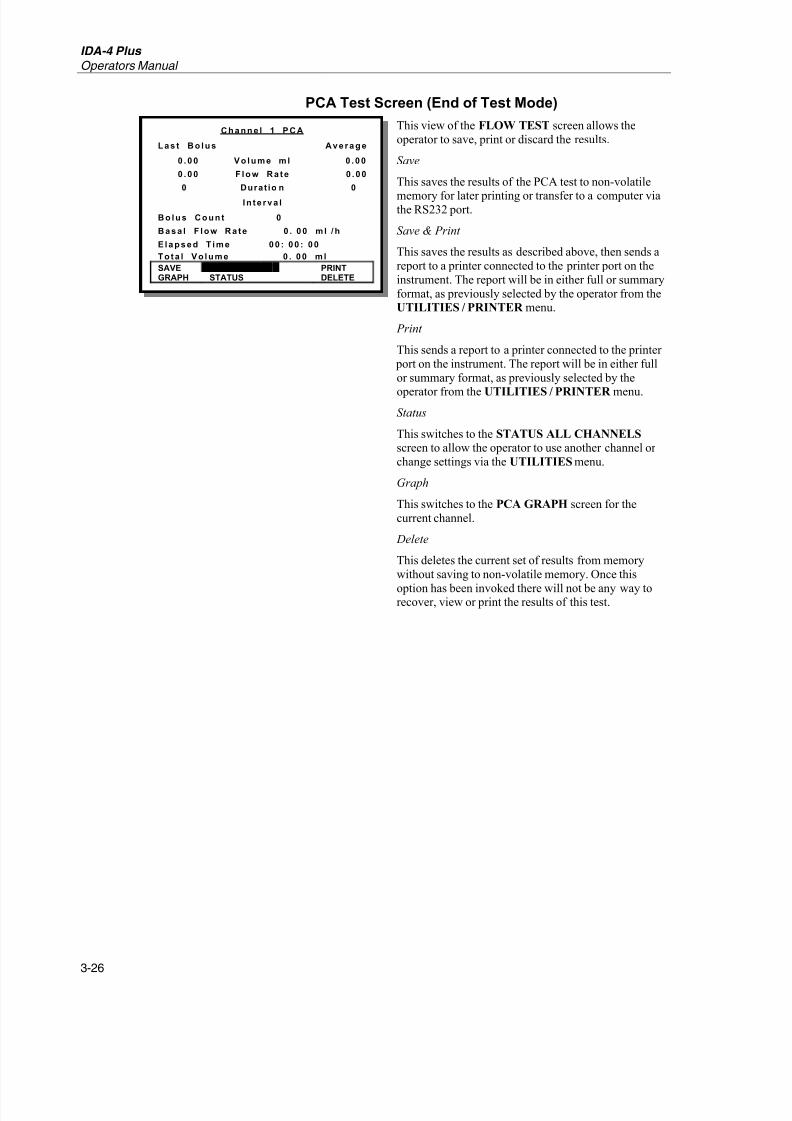
8/6/2019 analizador de bomba de infusión IDA4_Manual_Operacion
http://slidepdf.com/reader/full/analizador-de-bomba-de-infusion-ida4manualoperacion 48/74
IDA-4 Plus
Operators Manual
3-26
PCA Test Screen (End of Test Mode)
This view of the FLOW TEST screen allows the
operator to save, print or discard the results.
Save
This saves the results of the PCA test to non-volatile
memory for later printing or transfer to a computer viathe RS232 port.
Save & Print
This saves the results as described above, then sends a
report to a printer connected to the printer port on the
instrument. The report will be in either full or summary
format, as previously selected by the operator from theUTILITIES / PRINTER menu.
This sends a report to a printer connected to the printer
port on the instrument. The report will be in either full
or summary format, as previously selected by the
operator from the UTILITIES / PRINTER menu.
Status
This switches to the STATUS ALL CHANNELS screen to allow the operator to use another channel or
change settings via the UTILITIES menu.
Graph
This switches to the PCA GRAPH screen for the
current channel.
Delete
This deletes the current set of results from memory
without saving to non-volatile memory. Once this
option has been invoked there will not be any way torecover, view or print the results of this test.
Ch an n e l 1 P CA
L as t Bo l u s Aver ag e
0 . 00 V o l u m e m l 0 . 00
0 . 00 F l o w Ra te 0 . 00
0 Durat io n 0
I n te r va l
Bo l u s Co u n t 0
Basa l F l o w Ra te 0 . 00 m l / h
E l ap sed T i m e 00 : 00 : 00
T o ta l V o l u m e 0 . 00 m l
SAVE SAVE & PRINT PRINTGRAPH STATUS DELETE

8/6/2019 analizador de bomba de infusión IDA4_Manual_Operacion
http://slidepdf.com/reader/full/analizador-de-bomba-de-infusion-ida4manualoperacion 49/74
Infusion Pump Analyzer
Operating Instructions 3
3-27
PCA Graph Screen
The PCA GRAPH screen displays the available data in
a bar graph format. The amplitude of each spikerepresents the flow rate at which each bolus is
administered. The width of each spike represents the
time duration of that bolus. The gap between successive
spikes will represent the time interval between boluses.
Numerical representation of the total volume delivered
and the volume of the last bolus delivered will bedisplayed down the right of the graph.
Status
This switches to the STATUS ALL CHANNELS
screen to allow the operator to use another channel or
change settings via the UTILITIES menu.
View
This returns to the PCA TEST screen in either the
Measuring Mode or the End of Test Mode, depending
on which mode this screen was called from.
PCA Bolus Trigger Methods
The IDA-4 Plus has two methods of operating withPCA bolus triggering; automatic and manual. Some
PCA pumps provide a connector to allow the Patient
Demand to be requested. The IDA-4 Plus enables this
facility via the PCA Trigger / Remote Call Interface.
Automated Bolus Trigger
With pumps that can be triggered electrically the bolus
trigger signals are generated at one-second intervals,
starting before the end of the lockout period.
The programmed period before lockout time expires isadjustable from the TEST PARAMETERS SCREEN.
Manual Bolus Trigger
It is not possible to trigger some types of PCA pumps
directly. Examples are ambulatory devices that have the
trigger mounted on the pump case or pumps that use a
pneumatic trigger. With these pumps the operator willhave to press the BOLUS / TRIG prompt on the PCA
TEST screen at the same time as pressing the bolus
request button on the pump.
PCA Pump Testing Scenarios
Various scenarios under which a PCA pump could be
tested are considered in the following paragraphs.These scenarios may not be exhaustive and some
parameters may have to be changed to satisfy the testingrequirements of some pumps.
PCA Activity Only
The basic test scenario would have the PCA pump setup to supply an initial loading or bolus, then deliver a
series of boluses following a lockout period. The basal
rate will be set to zero.
Ch an n e l 1 P CA G RAP H
T Vol3 . 00
ml
Bo l V o l
1 . 00ml
Co u n t 3
00: 02: 00
STATUS VIEW
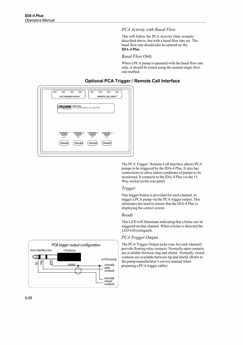
8/6/2019 analizador de bomba de infusión IDA4_Manual_Operacion
http://slidepdf.com/reader/full/analizador-de-bomba-de-infusion-ida4manualoperacion 50/74
IDA-4 Plus
Operators Manual
3-28
PCA Activity with Basal Flow
This will follow the PCA Activity Only scenario
described above, but with a basal flow rate set. The
basal flow rate should also be entered on the
IDA-4 Plus.
Basal Flow Only
When a PCA pump is operated with the basal flow rateonly, it should be tested using the normal single flow
rate method.
Optional PCA Trigger / Remote Call Interface
CHANNEL 1
READY
CH1 CH2
PCA TRIGGER OUTPUT REMOTE CALL INPUT
IDA4 Plus PCA TRIGGER/REMOTE CALL INTERFACE
CH3 CH4 CH1 CH2 CH3 CH4
TRIGGER
CHANNEL 2
READY
CHANNEL 3
READY
CHANNEL 4
READY
TRIGGER TRIGGER TRIGGER
The PCA Trigger / Remote Call Interface allows PCA pumps to be triggered by the IDA-4 Plus. It also has
connections to allow alarm conditions of pumps to be
monitored. It connects to the IDA-4 Plus via the 15
Way socket on the rear panel.
Trigger
One trigger button is provided for each channel, to
trigger a PCA pump via the PCA trigger output. This
eliminates the need to ensure that the IDA-4 Plus isdisplaying the correct screen.
Ready
This LED will illuminate indicating that a bolus can be
triggered on that channel. When a bolus is detected the
LED will extinguish.
PCA Trigger Output
The PCA Trigger Output jacks (one for each channel)
provide floating relay contacts. Normally open contactsare available between ring and shield. Normally closed
contacts are available between tip and shield. (Refer to
the pump manufacturer’s service manual when
preparing a PCA trigger cable).
from interface box 1/4”phono
shield
PCA trigger output configuration
normally opencontacts
normally closed contacts
to PCA pump
t i p
r i n g
g n d

8/6/2019 analizador de bomba de infusión IDA4_Manual_Operacion
http://slidepdf.com/reader/full/analizador-de-bomba-de-infusion-ida4manualoperacion 51/74
Infusion Pump Analyzer
Operating Instructions 3
3-29
Remote Call Input
Any change in the Remote Call Input jacks (one for
each channel) will be detected by the IDA-4 Plus. For
voltage output remote call, connect the higher potentialto the ring and the lower potential or ground to the tip.
For relay output remote call, the polarity does not
matter. (Refer to the pump manufacturer’s service
manual when preparing a remote-call input cable).
to interface box 1/4” phono
shield
remote call input configuration
high +low, -
from pump t
i p
r
i n g
g
n d

8/6/2019 analizador de bomba de infusión IDA4_Manual_Operacion
http://slidepdf.com/reader/full/analizador-de-bomba-de-infusion-ida4manualoperacion 52/74

8/6/2019 analizador de bomba de infusión IDA4_Manual_Operacion
http://slidepdf.com/reader/full/analizador-de-bomba-de-infusion-ida4manualoperacion 53/74
Infusion Pump Analyzer
Operating Instructions 3
3-31
Dual Rate Test Screen
This is the screen that allows the operator to control the
dual rate flow test. It has a menu across the bottom of the screen that changes to reflect the progress of the
test.
Dual Rate Test Screen (Prime Mode)When the screen is first displayed the operator is
prompted to prime the channel. This is essential to
ensure that the measuring circuit is filled with fluid.
Prime
This prompt stays on the screen while there is any air in
the measuring circuit. Pressing ENTER while this
prompt displays PRIME will not have any effect. Asthe circuit is primed the prompt changes to START.
There may be some flickering between PRIME and
START as bubbles percolate through the system.
Status
This invokes the STATUS ALL CHANNELS screen.
ESC
Selecting ESC or pressing ESC on the external
keyboard takes the operator back to the CHANNEL
SETUP menu.
Dual Rate Test Screen (Start Mode)
When the measuring circuit is primed successfully the
screen advances to the Start Mode.
Auto-Start
Pressing ENTER on this option puts the IDA-4 Plus into AutoSTART mode. The prompt will flash until the
instrument detects that the fluid is flowing, then startthe test.
Start
When the channel is primed this option is displayed and
enabled. Pressing ENTER while this item is selectedstarts the test and advances to the Measuring Mode.
Status
This invokes the STATUS ALL CHANNELS screen.
ESC
Selecting ESC or pressing ESC on the externalkeyboard takes the operator back to the CHANNEL
SETUP menu.
CHANNE L 1 DUAL F L O W
FLOW 1 0.00
ml /h
VOLUME 0.00 ml
FLOW 2 0. 00 VOLUME
Ela pse d Tim e 00: 00: 00
Ins t. Flo w 0. 00 ml /h
Bac k Pres sur e 0. 00 psi
PRIME STATUS ESC
CHANNE L 1 DUAL F L O W
FLOW 1 0.00
ml /h
VOLUME 0.00 ml
FLOW 2 0. 00 VOLUME
Ela pse d Tim e 00: 00: 00
Ins t. Flo w 0. 00 ml /h
Bac k Pres sur e 0. 00 psi
AutoSTART START STATUS ESC

8/6/2019 analizador de bomba de infusión IDA4_Manual_Operacion
http://slidepdf.com/reader/full/analizador-de-bomba-de-infusion-ida4manualoperacion 54/74
IDA-4 Plus
Operators Manual
3-32
Dual Rate Test Screen (Measuring Mode)
When the test is started, the screen enters measuring
mode for the primary flow rate (Flow 1) as shown. Thisenables further menu options.
As the test progresses the IDA-4 Plus detects the
change in flow rate and changes the display toemphasize the secondary flow rate (Flow 2). The
Instantaneous Flow Rate shall be displayed in this
screen between the elapsed time and backpressurereadings.
Status
This invokes the STATUS ALL CHANNELS screen.
Graph
This switches to the DUAL FLOW GRAPH screen for the current channel.
Flow
This ends the current test, clear the values from the
screen and proceeds to the FLOW TEST screen ineither Prime or Start mode, depending on the current
state of the transducer.
Occlusion
This ends the current test, clear the values from the
screen and proceed to the OCCLUSION TEST screenin Wait mode.
End
Ends the test and advances to the End of Test Mode.
CHANNE L 1 DUAL F L O W
FLOW 1 0.00
ml /h
VOLUME 0.00 ml
FLOW 2 0. 00 VOLUME
Ela pse d Tim e 00: 00: 00
Ins t. Flo w 0. 00 ml /h
Bac k Pres sur e 0. 00 psi
STATUS GRAPH FLOW OCCL END
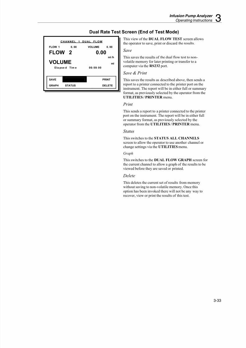
8/6/2019 analizador de bomba de infusión IDA4_Manual_Operacion
http://slidepdf.com/reader/full/analizador-de-bomba-de-infusion-ida4manualoperacion 55/74
Infusion Pump Analyzer
Operating Instructions 3
3-33
Dual Rate Test Screen (End of Test Mode)
This view of the DUAL FLOW TEST screen allows
the operator to save, print or discard the results.
Save
This saves the results of the dual flow test to non-
volatile memory for later printing or transfer to acomputer via the RS232 port.
Save & Print
This saves the results as described above, then sends a
report to a printer connected to the printer port on theinstrument. The report will be in either full or summary
format, as previously selected by the operator from the
UTILITIES / PRINTER menu.
This sends a report to a printer connected to the printer port on the instrument. The report will be in either full
or summary format, as previously selected by the
operator from the UTILITIES / PRINTER menu.
Status
This switches to the STATUS ALL CHANNELS
screen to allow the operator to use another channel or change settings via the UTILITIES menu.
Graph
This switches to the DUAL FLOW GRAPH screen for
the current channel to allow a graph of the results to beviewed before they are saved or printed.
Delete
This deletes the current set of results from memorywithout saving to non-volatile memory. Once this
option has been invoked there will not be any way to
recover, view or print the results of this test.
CHANNE L 1 DUAL F L O W
FLOW 1 0. 00 VOLUME 0. 00
FLOW 2 0.00
ml /h
VOLUME ml
Ela pse d Tim e 00: 00: 00
SAVE SAVE & PRINT PRINT
GRAPH STATUS DELETE

8/6/2019 analizador de bomba de infusión IDA4_Manual_Operacion
http://slidepdf.com/reader/full/analizador-de-bomba-de-infusion-ida4manualoperacion 56/74
IDA-4 Plus
Operators Manual
3-34
Dual Rate Graph Screen
The DUAL FLOW RATE screen displays the average
flow rate for the primary and for the secondary flows.Deviation marks as described in the single flow rate
graph are shown for the primary flow rate only.
Text at the right of the graph displays the primary flowrate, volume delivered at that rate and the duration of
the primary flow. This is followed by the secondary
flow rate and volume delivered at the secondary flowrate.
Status
This switches to the STATUS ALL CHANNELS
screen to allow the operator to use another channel or change settings via the UTILITIES menu.
View
This returns to the DUAL RATE TEST screen in either the Measuring Mode or the End of Test Mode,
depending on which mode called this screen.
CHANNE L 1 DUAL F L O W
PrimaryF 55. 25V 0. 9300: 01: 00
SecondaryF 5. 19V 0. 3500: 04: 01
00: 05: 06
STATUS VIEW
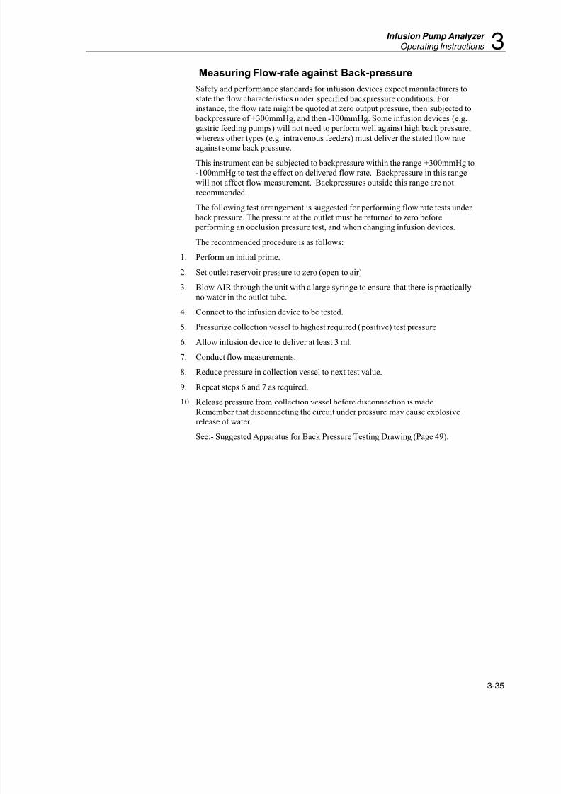
8/6/2019 analizador de bomba de infusión IDA4_Manual_Operacion
http://slidepdf.com/reader/full/analizador-de-bomba-de-infusion-ida4manualoperacion 57/74
Infusion Pump Analyzer
Operating Instructions 3
3-35
Measuring Flow-rate against Back-pressure
Safety and performance standards for infusion devices expect manufacturers to
state the flow characteristics under specified backpressure conditions. For instance, the flow rate might be quoted at zero output pressure, then subjected to
backpressure of +300mmHg, and then -100mmHg. Some infusion devices (e.g.
gastric feeding pumps) will not need to perform well against high back pressure,
whereas other types (e.g. intravenous feeders) must deliver the stated flow rateagainst some back pressure.
This instrument can be subjected to backpressure within the range +300mmHg to-100mmHg to test the effect on delivered flow rate. Backpressure in this range
will not affect flow measurement. Backpressures outside this range are not
recommended.
The following test arrangement is suggested for performing flow rate tests under
back pressure. The pressure at the outlet must be returned to zero before performing an occlusion pressure test, and when changing infusion devices.
The recommended procedure is as follows:
1. Perform an initial prime.
2. Set outlet reservoir pressure to zero (open to air)
3. Blow AIR through the unit with a large syringe to ensure that there is practically
no water in the outlet tube.
4. Connect to the infusion device to be tested.
5. Pressurize collection vessel to highest required (positive) test pressure
6. Allow infusion device to deliver at least 3 ml.
7. Conduct flow measurements.
8. Reduce pressure in collection vessel to next test value.
9. Repeat steps 6 and 7 as required.
10. Release pressure from collection vessel before disconnection is made.
Remember that disconnecting the circuit under pressure may cause explosiverelease of water.
See:- Suggested Apparatus for Back Pressure Testing Drawing (Page 49).

8/6/2019 analizador de bomba de infusión IDA4_Manual_Operacion
http://slidepdf.com/reader/full/analizador-de-bomba-de-infusion-ida4manualoperacion 58/74

8/6/2019 analizador de bomba de infusión IDA4_Manual_Operacion
http://slidepdf.com/reader/full/analizador-de-bomba-de-infusion-ida4manualoperacion 59/74
4-1
Chapter 4
Maintenance, Service and CalibrationThis chapter discusses routine maintenance
and calibration procedures for the user.
User Care and Maintenance
Storage
Do not leave water inside the unit when storing or shipping. At the factory
units are ‘dried’ before shipping by connecting a suction pump to each of
the FLUID OUTLET connectors in turn for 2 minutes. This is performed with
the unit switched off and disconnected from the supply. Connection to a
medical suction pump will not harm the unit.
Handling
The equipment will be damaged if dropped or subjected to excessive shock.
Use
For best performance the unit should be regularly used, and may be left
between test sessions with water inside.
Care of the Instrument Case
Clean using a damp cloth with a mild detergent. The molded front panel
and rear housing can be damaged if an abrasive cleaner is used.
Do not use any type of solvent to clean the case.
Cleaning the Inside of the Instrument
Over a long period of use there may be some ‘scaling’ of the inside tubes
etc. Also there may be organic growth inside the measuring system. We
suggest occasional cleaning (e.g. every 3 months) as follows:
1. Inject 20 ml of warm detergent solution into each channel that is fitted
with a measuring transducer and leave for at least 5 minutes. Then
flush out with water.
Hypochlorite / Chlorine Bleach is not allowed, nor any alcohol based agent

8/6/2019 analizador de bomba de infusión IDA4_Manual_Operacion
http://slidepdf.com/reader/full/analizador-de-bomba-de-infusion-ida4manualoperacion 60/74
IDA-4 Plus
Operators Manual
4-2
User Performance Check
The Calibration is set at the factory. For accurate Re-Calibration or
resetting of Calibration the unit must be returned via the dealer.
Users may wish to check for faults after a period of use or after shock to the
unit. We suggest the pressure measurement performance is checked by
connecting an external pressure gauge and syringe to the fluid inletconnector of each channel fitted. Initiating an occlusion test on each
channel in turn (each Fluid-inlet must be vented to atmosphere at the start
of the test), and then raise the pressure to 1 Bar on each channel fitted and
checking that the pressure readings are approximately as expected.
We suggest that flow measurement performance is checked using a syringe
pump which has been calibrated with an accurate burette. We suggest
checking each channel at 20 ml/hr. Please note that a new syringe must be
fitted before performing this test, and the syringe pump must be allowed
time to come up to speed before starting the Flow Test on each channel.

8/6/2019 analizador de bomba de infusión IDA4_Manual_Operacion
http://slidepdf.com/reader/full/analizador-de-bomba-de-infusion-ida4manualoperacion 61/74
A-1
Appendix A
Infusion Devices Delivery MethodsThis Appendix gives an overview
of and discusses different types of Infusion Devices and Delivery Methods
Infusion Devices: An Overview
Infusion devices may be grouped into two types, gravity controllers and infusion pumps.
Gravity Controllers
are powered devices which control the flow of the infusion to the desired rate by
constricting the infusion line. There is no pumping action, i.e. they rely solely on the heightof the fluid bag above the patient.
Regulators are a simple manual form of this device which do not rely on electronics and
are generally single use.
This type includes:
Drip-Rate Controllers
These are devices in which the desired flow is set in drops per minute. The electronicmechanism then counts the drops as they fall through a drop chamber and constricts the
infusion line to achieve the desired flow.
Volumetric Controllers
These are devices resembling the above, but in which the desired flow rate is set in
milliliters per hour. The device calculates the conversion from drops per minute to
milliliters per hour.
Infusion Pumps
Infusion pumps are powered devices to provide the desired flow rate by a positive pumping
action.
This type includes:
Drip-Rate Pumps
These are devices in which the desired flow rate is set in drops per minute. The electronicmechanism then counts the drops as they fall through the drop chamber and the appropriate
volume is infused into the patient, usually by a linear peristaltic pumping action.
Volumetric Pumps
These are devices in which the desired flow rate is set in milliliters per hour. A variety of pumping means incorporating a known volume displacement are used ( for example, a
specified cassette mechanism). A drop sensor may be present for the purpose of indicatingan empty infusion bag, or for the detection of inaccuracies in delivered volume.
Syringe Pumps (‘Syringe Drivers’)
These are devices in which a syringe or cartridge containing the solution to be infused issecured in the pump and a plunger is driven forwards at a predetermined rate to achieve the
desired infusion rate.

8/6/2019 analizador de bomba de infusión IDA4_Manual_Operacion
http://slidepdf.com/reader/full/analizador-de-bomba-de-infusion-ida4manualoperacion 62/74
IDA-4 Plus
Operators Manual
A-2
Patient Controlled Analgesia (PCA) Pumps
These are devices in which the patient is able to initiate a dose of the infusion solution for
the relief of pain. Access by the patient to the pump itself is prevented, pre-programmed
restraints are placed on the parameters of the boluses and, in addition, a basal rate deliveryof solution outside the control of the patient may be provided.
Pumps for Ambulatory UseThese are small and light enough to be carried around by the patient without undulyinterfering with everyday activities.
Anesthesia Pumps
These are syringe pumps suitable for the administration of anesthetic agents and unsuitablefor any other use.
Multi-Purpose Pumps
These can be made to perform as one of the above listed pump.
Other Devices
These include non-electrically powered devices, which do not have electrically generatedalarm signals. Some of them are charged with a syringe and then deliver their output moreor less continuously, with flow being controlled by a flow-regulating means, such as a
capillary tube. This type of pumping device may use an elastomeric membrane, which,
once expanded, provides sufficient force to drive the infusion. Applications include PCAands emergency situations.
The performance of non-electrically powered devices is generally inferior to those typesmentioned above, but they may have other advantages, such as simplicity and the ability to
operate in difficult environments.
Spring driven clockwork, and gas powered infusion devices are also available.
Flow Regulators
which are manually set, non-powered, devices which appear in a variety of forms andwhich clamp onto, or are inserted in, the line. They usually have a rotary dial to give to
give an indication of expected flow rate. Some of these devices claim to compensate for venous back pressure and maintain consistent flow.
The performance of non-electrically powered devices is generally inferior to those types
mentioned, but they may have other advantages, such as simplicity and the ability tooperate in difficult environments.
Infusion Devices: A More Detailed Look
The previous section introduced the infusion devices that are generally to be found onwards, in intensive therapy units (ITUs) and theaters. In this section each device will be
described with comments about safety, performance and suitability for application.
Gravity Controllers
General
Infusion controllers rely solely on gravity to provide the infusion pressure andconsequently, the fluid container must be placed at an adequate height above the infusion
site for the desired flow to take place. A drop sensor attached to the drip chamber of the
administration set monitors the drip-rate. A variable mechanical clamp within the device,acting on the delivery tube, controls the flow and hence the drip-rate, to achieve the set
rate.

8/6/2019 analizador de bomba de infusión IDA4_Manual_Operacion
http://slidepdf.com/reader/full/analizador-de-bomba-de-infusion-ida4manualoperacion 63/74
Infusion Pump Analyzer
Infusion Devices Delivery Methods A
A-3
Control against over-infusion is effective, but increased resistance to flow may result in
under-infusion. The better controllers incorporate a flow status system in which users are provided with a visual indication of increased resistance to flow, which could mean that
there is a ‘positional IV’ problem (catheter impinging on the vein wall) or even infiltration
(extra-vascular infusion in which the catheter has punctured the vein and the infusion
solution is infiltrating surrounding tissue). An alarm operates when there is a significant
departure from the set drip-rate. No alarm should ever be regarded as being a nuisance.
Controllers are recommended for use in many lower risk applications, involving fluidreplacement therapy where their low delivery pressure, early warning of problems at the
infusion site, inability to pump air and the reduced risk of extra-vascular infusion (due to
the low delivery pressure) are considerable advantages.
Drip-Rate Controllers
use standard solutions sets and although they look much like a pump, they have no
pumping mechanism. They are sometimes marked CONTROLLER. The flow rate isselected in drops per minute and controlled by battery or mains powered line occlusion
valves. Controls tend to be few and simple to operate. More advanced models incorporate
a flow status system, which gives a visual indication of resistance to flow. A drop sensor
is always included.
Drip-rate controllers are suitable for the majority of lower risk infusions in which
volumetric accuracy is of lesser importance, see below.
Accuracy of Drip Controlled Devices
Because of the high accuracy of drop counting mechanisms used by gravity controllers, it
is natural to assume that volume delivery will be correct according to the conversion used -
it may not be.
The normal drops/ml for a set, or the value taken from a conversion chart, are approximate
and the actual drops/ml may differ considerably. The volume of fluid in a drop depends ona number of variables: the composition of the fluid, its temperature and surface tension; the
drip rate set; the size, shape and condition of the drop forming orifice. Most simple
aqueous solutions of electrolytes, lactates or dilute sugars, give drop volumes fairly closeto the expected nominal drops/ml, except at very low drip rates. However, total parenteral
nutrition (fat-soluble vitamins, solutions containing alcohol and some amino-acid
solutions) produce much smaller drops. The flow rate will therefore be lower than expectedand the infusion time will be increased. With all fluids, the drops/ml value falls (drop
volume rises) with increasing delivery rate.
For the majority of infusions, these variations are acceptable, but where volumetricaccuracy is considered to be critical, the use of a volumetric pump (or a syringe pump if
the volume to be infused is small) is essential.
Volumetric Controllers
are calibrated in milliliters per hour, have a drop sensor, may have more controls and
alarms than a drip-rate controller and may need a dedicated solution set or a disposable
‘rate clip’.
Volumetric controllers include compensation for drop size. The main problem is knowing
what compensation to apply, as drop size varies due to several factors. Volumetricaccuracy is dependent upon the compensation being correct under all circumstances. With
present technology, a number of compromises have to be accepted and a fluid code system
is usually adopted which groups like infusates together. It is generally considered that the
accuracy of delivery of these devices cannot be much better than ± 10% over a one-hour
period.
The only advantage of using a volumetric controller, rather than a drip-rate controller, is
that no calculations have to be made for the drip rate of the administration set and so this
potential source of error is eliminated.

8/6/2019 analizador de bomba de infusión IDA4_Manual_Operacion
http://slidepdf.com/reader/full/analizador-de-bomba-de-infusion-ida4manualoperacion 64/74
IDA-4 Plus
Operators Manual
A-4
Infusion Pumps
General
Common to all pumps is the ability to overcome resistance to flow by increased deliver
pressure. Pumps do not rely on gravity and can therefore be placed in almost anyreasonable position relative to the infusion site (but not too high). The delivery pressure
may rise to high values in some devices in the event of a catheter becoming occluded or displaced, with the danger of extra-vascular infusion. However, the default pressure isusually limited in modern pumps and some include a facility for setting very low occlusion
alarm pressures.
Generally Speaking, the performance of pumps is predictable and the volume to be infused(VTBI) can be set in the confident knowledge that it will be delivered. Associated with this
must come the understanding that these are electrically powered devices, having a number
of risks. They must be used with full knowledge of these risks and thorough training in
their operation.
Pumps are capable of accurate delivery of solution over a wider range of flow rates than
controllers, at both the low and high ends of the delivery range, and may be designed for specialist applications, to which they must then be restricted.
Drip - Rate PumpsThe flow rate is selected in drops per minute and this alone allows users to distinguishthem from volumetric pumps. A drop sensor attached to the drip chamber counts drops and
the pump then infuses the set drip rate into the patient.
Pumping is achieved either by the peristaltic action of rollers or, usually, by mechanicalfingers (linear peristaltic) on deformable tubing. This latter type of pump uses a standard
administration set, but rotary peristaltic pumps generally require softer tubing and special
sets are provided with a pumping insert made of suitable material. Pumps that use dropsensing as their means of control do not normally compensate for variation in drop size.
Controls are few and simple, with only rudimentary alarms to warn of any departure from
the set rate and some other malfunctions.
Air - in - line detection is rarely, if ever, provided and the occlusion response is poor, with
high pressures being reached. These pressures are so high that in practice the alarm would probably never activate during extra - vascular infusion.
Volumetric Pumps
These are the preferred pumps for medium and large flow rate and large volume infusions;
although some are designed specially to operate at low flow rates for neonatal use. All are
mains / battery powered, with rate being selected in milliliters per hour. Most use a linear
peristaltic pumping mechanism, but other mechanisms are available, such as cassettes.
Volumetric pumps usually incorporate a wide range of features, required for neonatal and
high-risk infusions, including air-in-line detector and comprehensive alarms. Thesefeatures, if properly used, make intravenous (IV) infusion much safer. There are, however,
some models either having, or which can be configured to have, a more basic specification,
making them suitable for lower risk infusions only.
Some volumetric pumps incorporate a drop sensor, but only for monitoring and alarm
purposes (such as empty container) and not as a primary control of delivery rate. Some are
designed to be used with standard PVC gravity administration sets.
In common with all pumps, they have the capability of developing high delivery pressures
(but not as high as drip-rate pumps) and due regard must be paid to this. However, in most pumps of this type, the pressure is limited to a pre-set value above which the pump will
alarm.
Volumetric pumps generally incorporate the following features:

8/6/2019 analizador de bomba de infusión IDA4_Manual_Operacion
http://slidepdf.com/reader/full/analizador-de-bomba-de-infusion-ida4manualoperacion 65/74
Infusion Pump Analyzer
Infusion Devices Delivery Methods A
A-5
automatic alarm and shut down if air enters the system; pre-set control of total volume to
be infused with digital readout of volume infused; automatic switching to keep vein open(KVO) rate at the end of the infusion; comprehensive alarm systems; automatic switch
over to internal battery operation on failure of mains supply, with the facility to use the
device on internal battery power only, if no mains power is available (for example during
transportation); other features often available are micro and macro delivery modes,
computer interface, operator-call alarm, primary and secondary (‘piggyback’) infusion
capability and a technical memory log, which can record the last few hundred operationsfor incident analysis. Typically, most volumetric pumps will perform satisfactorily at rates
down to 5 ml/h. If you wish to infuse at lower rates, you should check the trumpet graph.
Below 1 ml/h, the performance should be checked by referring to the manufacturer.
Syringe Pumps
These are low volume, high accuracy devices designed to infuse at low flow rates and are
typically calibrated for delivery in milliliters per hour, typically 0.1 to 99 ml/h. Many pumps will accept different sizes and different brands of syringe (up to 50/60 or even 100
ml), but the pumps must be set up for a particular type and size of syringe in use, unless the
pump detects the syringe size and type automatically. Total dose volume (withoutrefilling) is limited to the size of the syringe used. They are mains and/or battery powered
and tend to cost less than volumetric pumps.
Programming in units other than milliliters per hour may be possible, with some having a bolus facility whereby a given volume may be infused in a short time. In the past, syringe
pumps had few alarms, but the trend has moved towards a comprehensive alarm system
which guards against unsafe operation.
At low flow rates, delivery from a syringe pump is likely to be more uniform than that
from a volumetric pump and the resultant short-term fluctuations are of much smaller
magnitude. There have been problems with backlash (slackness which causes start-up andalarm delays) in the pump overcome by careful attention at the design stage. Following the
manufacturer’s instructions for priming the pump will reduce such problems. Features
available vary so widely that each model must be separately assessed, but the more recentand more expensive models have much to offer, including delivery pressure displays.
Important points and advice for safe operation: the syringe barrel and plunger must be
located securely in accordance with the manufacturer’s instructions. Only by doing this
will the instrument’s safety features be fully operational and free-flow (syphonage) beavoided. Use the smallest syringe the pump will accept, and which is able to hold therequired volume of drug. As in general, occlusion response times are decreased when using
small syringes. Also, small syringes improve the consistency of the flow and reduce bolus
volume when the occlusion is removed.
PCA Pumps
Most of these pumps have the capability of mains or battery operation and are designed
specifically for this application. They are typically syringe pumps, as the total volume of
drug to be infused can usually be contained in a single-use syringe. Some PCA pumps are based on volumetric designs. The difference between a PCA pump and a normal syringe
pump is the provision of a facility to enable patients to deliver a bolus dose themselves. A
PCA pump may be programmed by clinical staff, to deliver a pre-set bolus on demand,with a pre-set lock-out time between boluses. In addition to the bolus delivered on patient
demand, PCA pumps may also be programmed to deliver a basal rate (continuous low rate
infusion). Examples of programming options are:
Loading dose; continuous infusion; continuous infusion with bolus on demand;
Bolus on demand only, with choice of units (ml or µg/ml, etc) and variable lockout time;drug concentration;
Once programmed, access to the control of the pump is usually only permitted by a key or software code but in some cases, limited patient access is allowed in order to change some
parameters.

8/6/2019 analizador de bomba de infusión IDA4_Manual_Operacion
http://slidepdf.com/reader/full/analizador-de-bomba-de-infusion-ida4manualoperacion 66/74
IDA-4 Plus
Operators Manual
A-6
A feature of most PCA pumps is a memory log, which can be accessed either through the
display, or downloaded via a printer or computer. This enables the clinician to determinewhen and how often, a demand has been made by the patient and what total volume of
drug has been infused over a given time.
There is a range of miniature battery powered volumetric pumps designed for PCAapplications and having disposable internal fluid reservoirs.
With PCA pumps, protection against free-flow is important, particularly as the patient may be unsupervised for some of the time.
Pumps for Ambulatory Use
are of two types, miniature syringe drivers and miniature volumetric pumps. Because of
the size of the devices, the available battery capacity is low and continuous pumping is notfeasible. Most ambulatory pumps, therefore, give an output in the form of a small bolus
delivered every few minutes. For the same reason, and because space is at a premium, very
few alarms are provided. Usually, warning indicators are restricted to flashing light toshow pump running and an audible alarm to indicate occlusion, or end of infusion.
Some non-electrically powered ambulatory pumps for PCA applications are appearing on
the market, using, for example, elastomeric balloons as the energy source.
Miniature Syringe Pumpscan easily be carried in a pocket or handbag, or worn by the patient. Most are battery
powered (a few are spring-driven), have few controls and the minimum of alarms. They
were developed from early syringe pumps accepting small volume syringes for intermittent bolus delivery via routes other than IV, typically subcutaneous infusion of insulin.
However, pumps are now available that are specifically designed for IV infusions, and areuseful in cytotoxic chemotherapy, pain relief and other applications where very small
volumes are to be infused over periods of days, rather than hours, and where the patient is
at home rather than in a hospital ward.
They can typically accept syringes between 2 and 10 ml and are able to achieve very lowrates of delivery. Because of this ability to accept various sizes of syringe, these pumps
may require the rate to be set in millimeters per day, that is, linear travel of syringe plunger
against time. They will be able to achieve the linear rate with considerable accuracy.
Calculations, which depend on the syringe used, may be required to convert from flow rateto linear travel per unit time.
The volumetric accuracy, however, can be variable, depending on the rate set, the fluid andsyringe used and the type of tubing employed. At the very low infusion rates which can be
selected (a few microliters per hour), some of the infusate may migrate through the walls
of the tubing and never actually reach the patient.
Miniature Volumetric Pumps
use removable reservoirs which contain the solution within the pump. Some may offer a
large variety of programming options. Those pumps having bolus on demand, as well as basal rate, are also suitable for PCA pumps.
Anesthesia Pumps
These are syringe pumps designed for use in anesthesia or sedation and must be used only
for this purpose. They should be clearly labeled ANESTHESIA PUMP and should berestricted to operating and high dependency areas. They are designed so that the rate may
be changed and other functions accessed immediately, whilst infusing. They need to infuse
over a higher flow rate range than normal syringe pumps and have a high bolus ratefacility, so that the induction dose may be delivered quickly, with a single operation.
Because of their application, these pumps may have a number of specific features such as:
Programming for body weight and drug concentration; drug specificsmart-card system which automatically calibrates the pump for the drug

8/6/2019 analizador de bomba de infusión IDA4_Manual_Operacion
http://slidepdf.com/reader/full/analizador-de-bomba-de-infusion-ida4manualoperacion 67/74
Infusion Pump Analyzer
Infusion Devices Delivery Methods A
A-7
being infused; built-in drug libraries; interface for computer control and
monitoring.
If these facilities are software enabled, by programming or smart card for example, in a
pump that is otherwise suitable for other applications, they must be disabled before these
pumps are used in any other application. Management must initiate policies to ensure thatthis is done. If these facilities cannot be locked out, in no circumstances should these
pumps be used for any other application.

8/6/2019 analizador de bomba de infusión IDA4_Manual_Operacion
http://slidepdf.com/reader/full/analizador-de-bomba-de-infusion-ida4manualoperacion 68/74
IDA-4 Plus
Operators Manual
A-8

8/6/2019 analizador de bomba de infusión IDA4_Manual_Operacion
http://slidepdf.com/reader/full/analizador-de-bomba-de-infusion-ida4manualoperacion 69/74
B-1
Appendix B
Computer Control CommandsThis Appendix gives an overview
of computer commands necessary to control the IDA-4 Plus.
Overview
With the computer control feature, the user is provided more power and flexibility with theIDA-4 Plus. For example, automation of all channels can be achieved for a completely
paperless approach to documentation.
When using computer control, the front keypad will be inoperable. The Status All
Channels screen will be displayed and the menu prompts will guide the operator through
the prime sequence and indicate the type of test in progress.
Controlling the IDA-4 Plus with HydroGraph
The IDA-4 Plus can be operated using a computer running HydroGraph™ software.Follow the steps below to get started:
• Power off the IDA-4. Connect the provided serial communications null modem cable or Fluke Biomedical’s serial cable (PN 2392046) between the IDA-4 Plus serial port and the
computer. Make a note as to which PC communications port the cable is connected to.
• Power up the IDA-4 Plus and wait for the status all channels screen to appear on thedisplay.
• Make sure HydroGraph™ version 2.xx is installed on the computer.
• Once installed, start HydroGraph™ on the computer, connection should automatically
occur. If not, refer to the HydroGraph™ Operators manual for further details.

8/6/2019 analizador de bomba de infusión IDA4_Manual_Operacion
http://slidepdf.com/reader/full/analizador-de-bomba-de-infusion-ida4manualoperacion 70/74
IDA-4 Plus
Operators Manual
B-2
Controlling the IDA-4 Plus Using Serial Protocol
The IDA-4 Plus allows the operator full flexibility with regard to the RS232 port.Capabilities include receiving and sending data at baud rates of 300, 600, 1200, 2400,
4800, 9600, 19200 and 38400. The baud rate used for transmission is held in the IDA-4
Plus non-volatile memory and can be changed at any time by the operator. Other serial port
parameters are Parity: even, odd and none; Data Bits: 7,8; Stop Bits: 1,2.
Command Conventions
There are 2 types of commands used in the IDA-4 Plus. Commands that perform an actionwithout returning data, and commands that return data to the host computer. The ASCII
code commands are to be enclosed by square brackets. For example, to send a command to
end a communication session, type [BYE]. All commands instructing to perform a testneeds to have a channel number attached to the command. Some commands require more
information in addition to channel number in the command line. For example the Dual
Flow test requires definition of the primary rates and volume secondary rates and volume.
The following commands require only the channel number to execute:
[VOLn], [FLOWn], [PRESn], [PKPRESn], [PCATRIGn]
The following section describes the data pieces required to perform these tests via
computer control.
Perform a Flow Test [CnF,a,b,c]
This command starts a flow / volume test on the specified channel. The IDA-4 Plus status
all channels screen will prompt the operator to prime the channel. Once primed, theoperator will have to press the Start key on the IDA-4 Plus front panel or send the [CnF]
command again.
Parameters:
n = channel number
a = control number of device under test
b = technician name
c = set flow rate

8/6/2019 analizador de bomba de infusión IDA4_Manual_Operacion
http://slidepdf.com/reader/full/analizador-de-bomba-de-infusion-ida4manualoperacion 71/74

8/6/2019 analizador de bomba de infusión IDA4_Manual_Operacion
http://slidepdf.com/reader/full/analizador-de-bomba-de-infusion-ida4manualoperacion 72/74

8/6/2019 analizador de bomba de infusión IDA4_Manual_Operacion
http://slidepdf.com/reader/full/analizador-de-bomba-de-infusion-ida4manualoperacion 73/74
Infusion Pump Analyzer
Computer Control Commands B
B-5
Fetch the Current Pressure on a Channel [PRESn]
Returned to host:
[PRES, pppp,hh:mm:ss:mmm] <CR><LF>
Where:
pppp is the pressure in the selected units
hh:mm:ss:mmm is the time since the start of the test, formatted as:
hh Hours
mmMinutes
ss Seconds
mmm Milli-seconds
Fetch the Peak Pressure on a Channel [PKPRESn]
Returned to host:
[P
Where:
pppp is the peak pressure in the selected units
hh:mm:ss:mmm is the time since the start of the test, formatted as:
hh Hours
mm Minutesss Seconds
mmm Milli-seconds

8/6/2019 analizador de bomba de infusión IDA4_Manual_Operacion
http://slidepdf.com/reader/full/analizador-de-bomba-de-infusion-ida4manualoperacion 74/74
IDA-4 Plus
Operators Manual
ASCII Code Function Number of
Parameters
IDA-4 Plus
< - - >
BYE Terminates
Computer Control
0 - - >
POLL Returns # of
channels installed
0 < - - >
PRESUn Sets the pressure
units
n = Channel number - - >
CnF,a,b,c Starts a Flow Test 3,
n = Channel number
- - >
CnV,a,b,c Starts a Volume
Test
3,
n = Channel number
- - >
CnO,a,b,c Starts an Occlusion
Test
3,
n = Channel number
- - >
CnPCA,a,b,c Starts a PCA test 3,
n = Channel number
- - >
CnD,a,b,c,d,e,f Starts a Dual FlowTest
6,n = Channel number
- - >
END,n End a Test n = Channel number - - >
FLOWn Fetches current flow
rate
n = Channel number < - - >
VOLn Fetches current
volume
n = Channel number < - - >
PRESn Fetches current
pressure
n = Channel number < - - >
PKPRESn Fetches the peak
pressure
n = Channel number < - - >
PCATRIGn Requests the start of
a PCA trigger
n = Channel number - - >
Table B-1: ASCII Code Commands used in the Computer Control Protocol