safe6 hpa instrucitons
DESCRIPTION
abb switchgear instructionsTRANSCRIPT
Instruction 1VES 580901-902Edition 97-11
ABB Switchgear
12 kV switchgear manual
Safesix

CONTENTSPage
0. Access zones....................................................................................................................................................................................1
1. General description................................................................................................................................................................11.1. Standards................................................................................................................................................................................................3 1.2. Cubicle design ................................................................................................................................................................................41.2.1. Personnel safety..............................................................................................................................................................................5 1.2.2. Dimensions and weights.....................................................................................................................................................7 1.2.3. Busbars and downleads .....................................................................................................................................................8 1.2.4. PC intermediate wall with shields.........................................................................................................................8 1.2.5. Earthing.........................................................................................................................................................................................................8 1.2.6. Running gear and interlock system....................................................................................................................9 1.2.7. Temperature indicators.....................................................................................................................................................11 1.3. Power circuit breaker cubicle ..........................................................................................................................12 1.4. Load disconnector cubicle SFL.....................................................................................................................13 1.5. Load disconnector cubicle NAL/NALF..............................................................................................141.6. Disconnector cubicle ......................................................................................................................................................15 1.7. Metering cubicle......................................................................................................................................................................161.8 Sectioning cubicle................................................................................................................................................................171.9 Contactor cubicle..................................................................................................................................................................18
2. Contactor cubicle .....................................................................................................................................................................192.1. Erection requirements...................................................................................................................................................19 2.1.1. Lift truck...................................................................................................................................................................................................192.2. Floor..............................................................................................................................................................................................................202.2.1. Space requirements...............................................................................................................................................................212.3. Unloading ............................................................................................................................................................................................232.4. Moving in..............................................................................................................................................................................................232.5. Setting up............................................................................................................................................................................................242.6. Fitting busbars............................................................................................................................................................................272.6.1. Fitting busbars, light series.........................................................................................................................................272.6.2. Fitting busbars, heavy series ...................................................................................................................................282.7. Cubicle and system earthing..............................................................................................................................30 2.8. Fitting roof panels.................................................................................................................................................................31 2.9. Connecting power cables........................................................................................................................................31 2.10. Connecting control cables.....................................................................................................................................35 2.11. Post-tightening ..........................................................................................................................................................................37
3. Post-tightening ............................................................................................................................................................................38
4. Post-tightening ............................................................................................................................................................................414.1. Commissioning new switchgear ................................................................................................................414.2. Commissioning after stoppage for repair or other action .............................414.3. Commissioning after stoppage......................................................................................................................41
5. Operating instructions....................................................................................................................................................425.1. Circuit breakers HPA and HA............................................................................................................................425.1.1 Circuit breaker shift ................................................................................................................................................................435.1.2. Circuit breaker shift to operating position............................................................................................445.1.3. Circuit breaker shift to disconnected position...............................................................................455.2. Load disconnector SFL ..............................................................................................................................................475.2.1. Safesix SFL interlock chain ......................................................................................................................................475.2.2. Shifting load disconnector SFL ............................................................................................................................485.2.3. Shifting load disconnector SFL to operating position ......................................................485.2.4. Switching load disconnector on ........................................................................................................................495.2.5. Shifting load disconnector SFL to disconnected position .........................................495.2.6. Switching load disconnector off .........................................................................................................................495.3. Load disconnectors NAL 12/630, NALF 12/630 ..................................................................505.3.1. Operating NAL/NALF...........................................................................................................................................................52
6. Maintenance rules................................................................................................................................................................546.1. Switchgear cubicle maintenance ...............................................................................................................556.2. Lubricants...........................................................................................................................................................................................576.3. Cleaning agents........................................................................................................................................................................57
7. Accessories, spares and ancillary equipment ............................................................................58
8. Documentation references......................................................................................................................................60

1
Safesix 12 kV switchgear
0Access zones
Switchgear is not intended to be accessible to the generalpopulation. The access zone for operators is the service en-trance at the front of the switchgear. Only servicing personnelare allowed to open switchgear doors. All operation of a with-drawable switching or connecting unit must be with the doorsclosed.
1General description
ABB's Safesix switchgear series is divided into compartmentsand intended for indoor locations. It is available in three differentvoltage versions of 12, 17.5 and 24 kV. This documentation isfor the 12 kV version. The cubicles are sized for operatingcurrents of up to 3150 A and maximum 4000 A on the busbarsand a short-circuit current of up to 40 kA.
Safesix 12 kV switchgear is available in two forms:• Light series
Max. rated current 1600 A. Max. short-circuit current 31.5 kA.
• Heavy seriesMax. rated current 4000 A. Max. short-circuit current 40 kA.
The range comprises the following cubicles:• Circuit breaker cubicle, with SF6-breaker
• Switch disconnector cubicle, with SF6-or air-insulatedswitch disconnector
• Disconnector cubicle, with drawer-mounted disconnector
• Metering cubicle, with measuring transformers
• Sectioning cubicle, with withdrawable switching or con-necting unit
• Interconnection cubicle
• Contactor cubicle with vacuum contactor (max. 7.2 kV)
The withdrawable switching and connecting units have the fol-lowing functions:Circuit breaker Can make, carry and break operating
current and short-circuit current
Switch disconnector Mechanical electrical switch operat-ed manually. Can make, carry and

2
break normal operating current. Cancarry short-circuit current for a speci-fied period. Can close against short-circuit current and can be providedwith fuses and short-circuit pro-tection. NAL and NALF have visiblebreak points. SFL has mechanicalindication. Type of switch used pre-ferably where both switching densityand current are low.
Disconnector Operated manually and has visibledisconnection distance. Cannot con-nect current but can carry operatingand short-circuit current. Safesix hasa disconnector of drawer-mounteddesign that can be interlocked so thatit cannot be shifted when energised.
Contactor Electrical switch that is operated elect-rically and has an electrical or mechan-ical latch. Can make, carry and breaknormal operating current and carryshort-circuit current for a specifiedperiod. Can be supplied with fuses asshort-circuit protection. Type of switchused preferably where switchingdensity is high and current low.
Safesix 12 kV switchgear
Fig. 1. Examples of cubicle types in ABB Safesix range.
Circuit breakercubicle
Sectioning cubicle40 kA 800 - 3150 A
Disconnectorcubicle
Meteringcubicle
Switch disconnectorcubicle
Inter connectioncubicle
Contactorcubicle
Sectioning cubicle31.5 kA 630 - 1600 A

3
Standards complied with:SS-IEC 298.
Electrical requirements complied with:Rated voltage: 12 kV SS-IEC 298Test voltage: Impulse withstand voltage 75 kV
1.2/50 µs.Power frequency voltage 28 kV 50Hz, 1 min.
All voltage levels apply to earth and between phases (max.1000 m above sea level).Rated current: Busbars: 630, 800, 1250 and 1600 A
for light series.1250, 2000, 2500, 3150 and 4000 Afor heavy series. Circuit breakers and cubicles: 630,800, 1250 and 1600 A for lightseries. 800, 1250, 2000, 2500 and 3150 Afor heavy series.The above current values apply withenclosure IP3X, max. temperaturerise as per SS-IEC 298 table V atmax. average ambient temperature35°C and max. short-time tempera-ture 40°C.
Rated short-timecurrent: 25, 31.5 and 40 kA in one second.
25 and 31.5 kA in 3 seconds (option).Rated impulse currentpeak value: 2.5 x rated short-time current.
Mechanical requirements complied with:Enclosure: Outer enclosure IP3X according to
SS-IEC 298. Partitions IP2X as seenfrom withdrawable switching orconnecting unit compartment.
Environmental requirements complied with:Ambient temperature: As per SS-IEC 298, -5°C to +40°C.
Switchgear can be equipped to copewith difficult environments.
1.1. Standards
Safesix 12 kV switchgear

4
Cubicle frames and rear panels made of spot-welded 2 mmAluzink sheetsteel. Doors of 2.5 mm painted sheet steel.
Cubicles may either be backed up against a wall or placedwith sufficient clearance to leave the rear accessible. Theymay also be ordered with exhaust channels designed forminimum roof height 2650 mm.
Each cubicle is divided into a number of compartments:
• Busbar compartment
• Low-voltage compartment, with contents varying from in-stallation to installation. A detailed description of this com-partment appears in the documentation specific to eachorder
• Withdrawable switching or connecting unit compartment
• Cable compartment
All HV compartments (busbar compartment, cable compart-ment and withdrawable switching or connecting unit compart-ment) have individual upward pressure relief ducts with topcovers that opens by any overpressure in the respective com-partment.
1.2. Cubicledesign
Safesix 12 kV switchgear
Fig. 2a. Safesix cubicle space distribution.
Lead-in duct forexternal LV cables Busbar compartment
LV compartment
Compartment forwithdrawable switching
or connecting unit
PC partitions
Partition wall forcompartment division
Cable compartment
Instrument space
Low voltage box door andCombiflex framework
Upper door
Lower door
Air intake for cubicles withrated current ³ 1600 A
Racking mechanism

5
The front of cubicles for 1600 A or over is provided at thebottom with a cooling air intake to create sufficient ven-tilation. This intake is provided with a patented check valve.On 3150 A circuit breaker cubicles the lower door is alsoprovided with ventilation apertures.
Each cubicle is provided with lighting. The incandescentbulb can be replaced from the LV compartment and issituated outside the compartment rear wall.
Personnel safetyHigh voltages and currents can cause serious injuries, so theSafesix range is designed for maximum elimination ofaccident risks.
Contact safetyAs it is vitally important for servicing personnel to be protectedfrom inadvertent contact with energised parts, Safesix cubiclesare divided into compartments. Among other advantages, thisprevents access to energised busbars when disconnectedcircuit breakers are being inspected. The walls betweencompartments are partly transparent. The advantages of thisinclude being able to view the disconnection distance throughthe window in the LV compartment.
There is no contact protection inside the lowerdoor. The cable side has to be de-energised and be earthedby means of the earthing switch before opening the door.
Unauthorised access can be prevented by padlocking thehandles of both the upper and lower doors.
Arcing safetyThe outer enclosure has been arc-tested to SS-IEC 298.The front, rear and sides withstand the pressure caused byarcing faults. Safesix cubicles have also been successfullytested to SS-IEC 298 with breaker doors open.
Damage caused by arcing faults is extensive and costly,so their causes need to be eliminated despite the highdegree of personnel safety built into Safesix switchgear. Thefollowing are possible causes of flashover:
• Small animals, most commonly rats or mice, that maketheir way into HV spaces
• Overheating due to bad threaded connections, oxidised
CAUTION!
1.2.1.Personnelsafety
Safesix 12 kV switchgear

6
contacts or overload
• High overvoltages, e.g. during thunderstorms
• Objects such as tools inadvertently left behind
• Faulty or severely fouled components or cable ter-minations
The Safesix design incorporates the following measures toimprove the prevention of arcing:
• Holes in outer enclosure too small for even small animalsto make their way into HV spaces
• Erection instructions give torques for correct tightening ofthreaded connections
• Spring washers used in threaded connections of primaryconductors to control prestress forces even after anumber of temperature cycles and sagging of material
• Busbar monitoring by SafeGuard (option)
• Overvoltage limitation by surge arrestor (option)
• Arcing fault prevention by arc monitor (option) to trip thebreaker when it indicates a powerful arc combined withhigh current. This involves the development of pressurewaves that reach their maximum in a hundredth of asecond
Exhaust gas channels (option)For gathering and leading overpressure and flue gases away soas not to affect switching operations. As the channels lead tooutdoor outlets, the switchgear room is not pressurised or pol-luted by toxic arc gases.
Voltage indicator (option)Earthing medium-voltage switchgear is a safety risk. Tominimise it, the earthing should be effected inside closeddoors by means of earthing switches. Each cubicle is pro-vided with an interlock system to prevent incorrect ope-ration. It may also be provided with voltage indicators thatdisplay 1, 2 or 3 if the corresponding phase is energized.
SafeGuard (option)SafeGuard is a monitoring system covering, among otherthings, the temperatures of busbar joints and contacts in themain circuit. The continuous information thus provided helpsto eliminate the risk of arcing faults.
Safesix 12 kV switchgear
Fig. 2b. Voltage indicator
7
Temporary earthingSafesix switchgear is equipped with a patented earthingswitch that has the following features:
• It can be operated when the doors are closed
• It has making capacity up to 40 kA rms
• The window in the lower door makes it possible to seewhether the earthing switch is closed or open
• Illicit operation is prevented by interlocking by means of ablocking disc that closes the operating hole when thebreaker is in operating position or being shifted
TrainingIt is very important that operators and servicing personnel betrained in handling the equipment.
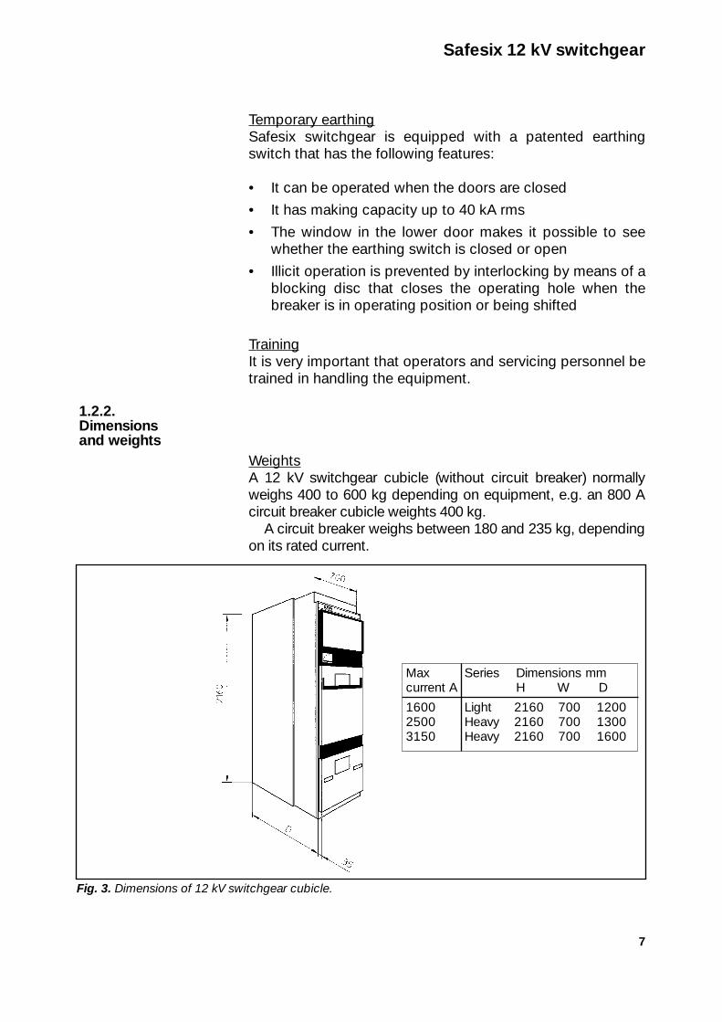
WeightsA 12 kV switchgear cubicle (without circuit breaker) normallyweighs 400 to 600 kg depending on equipment, e.g. an 800 Acircuit breaker cubicle weights 400 kg.
A circuit breaker weighs between 180 and 235 kg, dependingon its rated current.
1.2.2. Dimensions and weights
Safesix 12 kV switchgear
Fig. 3. Dimensions of 12 kV switchgear cubicle.
Max Series Dimensions mmcurrent A H W D
1600 Light 2160 700 12002500 Heavy 2160 700 13003150 Heavy 2160 700 1600

8
Busbars and droppers are normally supplied uninsulated butcan be supplied with insulation to order. Busbars are madeof copper with cross-section suited to the rated current.
The switchgear is of the drawer-mounted type. The with-drawable units can be cranked into and out of thecompartments. The withdrawable unit compartment and thebusbar compartment are separated by a partition ofpolycarbonate to prevent inadvertent contact with live partswhen the unit is removed. This partition incorporates sixshutters that are opened by the connecting bars when theunit reaches operating position.
The PC partition and the shutters provide IP3X as degreeof protection.
Fixed earth paths, system earthingSafesix has two alternative earthing arrangements.
The first is for each cubicle to be earthed separately, withterminals for connecting external earth conductors to theearth bar in each cubicle.
The other alternative has an earth bar running through thewhole switchgear, with terminals for connecting external
1.2.5. Earthing
1.2.4. PC-partition with shutters
1.2.3. Busbars anddroppers
Safesix 12 kV switchgear
Fig. 4. PC partitions with shutters (racking mechanism removed).
PC partitions
Shutters
Earthing switch shaft with position symbol
Box with earthing switch auxiliary contacts
and interlock magnets
9
earth conductors to the earth bar in each cubicle. The onlyearth connections of the station are in the outer cubicles.
Equipment items incorporated are earthed to the frame,except for the earthing switch and the voltage transformers,which have earthing wires to the earth bar of the cubicle.
Temporary earthingA standard fitting for temporary earthing of cable is anearthing switch permanently fitted in the cubicle. Any busbarearthing switch fitted will be on the righthand end cover. Anoption available is to equip the earthing switch with voltageindicators that display on the cubicle front.
The earthing switch is operated from the cubicle front bymeans of a crank. On earthing switch operation see section5.1.1, Shifting withdrawable units.
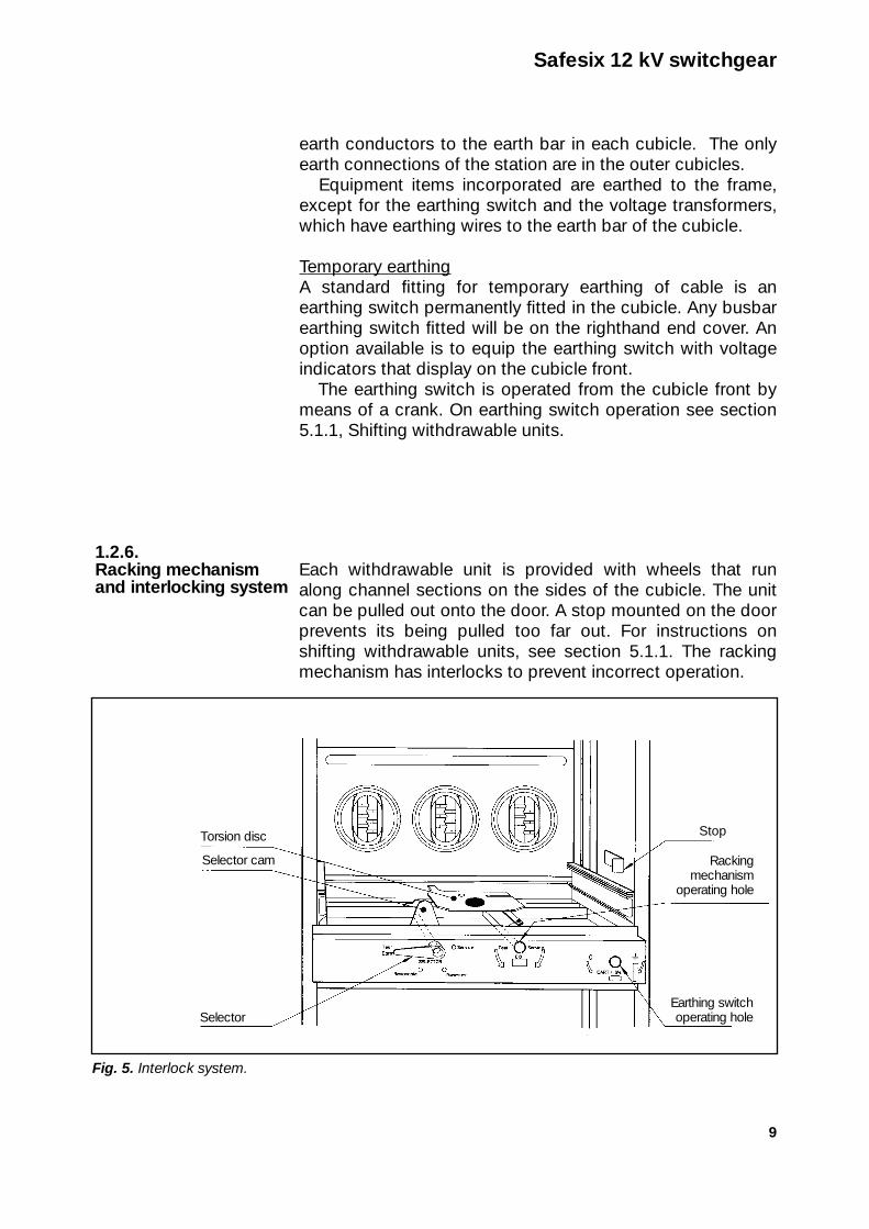
Each withdrawable unit is provided with wheels that runalong channel sections on the sides of the cubicle. The unitcan be pulled out onto the door. A stop mounted on the doorprevents its being pulled too far out. For instructions onshifting withdrawable units, see section 5.1.1. The rackingmechanism has interlocks to prevent incorrect operation.
1.2.6. Racking mechanism and interlocking system
Safesix 12 kV switchgear
Fig. 5. Interlock system.
Selector cam
Selector
Stop
Rackingmechanism
operating hole
Earthing switchoperating hole
Torsion disc

10
The interlock system has active interlocks (preventing accessto operating holes) that mechanically make it impossible to:
1. shift a closed circuit breaker (blocking disc covers rackingmechanism operating hole, selector rotation breaks controlcircuit)
2. shift a closed circuit breaker from test position to serviceposition (blocking device on righthand side of circuit breakerhits the stop)
3. close the circuit breaker while it is being shifted (duringwhich it has no control voltage)
4. shift the circuit breaker from disconnected position to ser-vice position if the earthing switch is closed (blocking disccovers racking mechanism operating hole)
5. connect the earthing switch if the circuit breaker is inservice position or being shifted (blocking disc coversearthing switch operating hole)
6. push the circuit breaker in from disconnected position if theracking mechanism is in the wrong position when the circuitbreaker is run in from the door (blocking devices on selectorshaft and torsion disc stop the circuit breaker)
7. place the selector in shift position if the circuit breaker isclosed (blocking device in circuit breaker prevents selectormovement)
8. place the selector in service position if the circuit breakeris not fully run in to service position (selector cam cannotenter recess in torsion disc)
9. run a withdrawable unit into a cubicle intended for ahigher rated current (prevented by blocking devices onrails and on withdrawable unit wheel undercarriage)
As an option the cubicle may be equipped with motorisedracking mechanism.
Safesix 12 kV switchgear
11
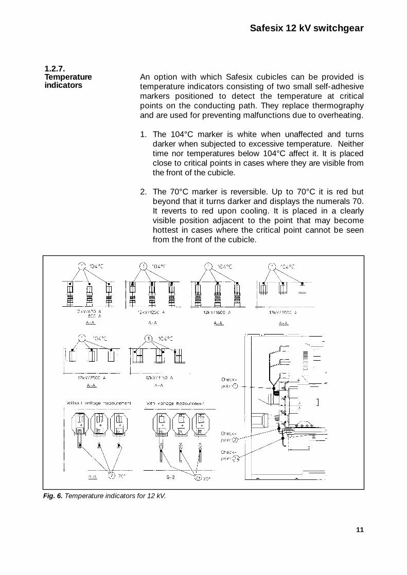
An option with which Safesix cubicles can be provided istemperature indicators consisting of two small self-adhesivemarkers positioned to detect the temperature at criticalpoints on the conducting path. They replace thermographyand are used for preventing malfunctions due to overheating.
1. The 104°C marker is white when unaffected and turnsdarker when subjected to excessive temperature. Neithertime nor temperatures below 104°C affect it. It is placedclose to critical points in cases where they are visible fromthe front of the cubicle.
2. The 70°C marker is reversible. Up to 70°C it is red butbeyond that it turns darker and displays the numerals 70.It reverts to red upon cooling. It is placed in a clearlyvisible position adjacent to the point that may becomehottest in cases where the critical point cannot be seenfrom the front of the cubicle.
1.2.7. Temperatureindicators
Safesix 12 kV switchgear
Fig. 6. Temperature indicators for 12 kV.

12
Data
Rated current A 630, 800, 1250, 1600, 2000, 2500, 3150
Rated voltage kV 12Insulation level kV 28/75Insulation level kV 38/75 (option)Rated short-timecurrent peak value kA 62.5, 79, 100Rated short-time current, 1 s kA 25, 31.5, 40Rated short-timecurrent, 3 s kA 25, 31.5 (option)
This cubicle contains an SF6-circuit breaker (describedseparately) of the withdrawable type and can be provided withcurrent transformers, voltage transformers, earthing switch andcable fastenings. In the light series (max. 1600 A) four parallelcables can be connected. In the heavy series there is space forup to six parallel cables. The cubicle incorporates interlocks toprevent the connection of undersized units.
The withdrawable unit can be shifted inside the closed door,thereby creating a disconnection distance that can be viewedthrough the window in the LV compartment (see Fig. 7).
1.3.Circuit breakercubicle
Safesix 12 kV switchgear
Fig. 7. Circuit breaker cubicle.
Window in low voltagecompartment

13
Contains an SF6-switch disconnector which is drawer-mountedand placed in the withdrawable unit cell. The rated current is upto 630 A without fuses and up to 100 A with high-power fuses.
The switch disconnector is operated manually inside theclosed door by means of a control lever. For fuse replacementthe unit has to be pulled out onto the door (see separateinstructions 1VEH 580901-901. The racking mechanism can beused inside the closed door to shift the withdrawable unit todisconnected position, thereby creating a disconnection dis-tance that can be viewed through the window in the bottom ofthe LV compartment. This cubicle can be used for up to 20 kA ifthe withdrawable unit has no HV fuses or for 40 kA with fuses.The upper door is extended by 40 mm, making a total cubicledepth of 1375 mm.
1.4.Switch dis-connectorcubicle SFL
Safesix 12 kV switchgear
Fig. 8. Switch disconnector cubicle with SFL.
Window in low voltagecompartment

14
Contains a drawer-mounted switch disconnector in the with-drawable unit cell.
The switch disconnector is operated manually inside theclosed door by means of a control lever. It can be providedwith high-power fuses up to 100 A. For fuse replacement thewithdrawable unit has to be pulled out onto the door. It has avisible disconnection distance at the knives, so it has nodisconnected position in the cubicle. It is therefore con-nected in service position when just inside the door. Thiscubicle can be used for 40 kA if the withdrawable unit hasfuses and for 25 kA without fuses. It can be provided withcurrent and voltage transformers and an earthing switch.
1.5.SwitchdisconnectorcubicleNAL/NALF
Safesix 12 kV switchgear
Fig. 9. Switch disconnector cubicle NAL/NALF.
Window in low voltagecompartment

15
Same construction as the circuit breaker cubicle. The with-drawable disconnector has the same contact positions in theconducting path as the corresponding circuit breaker. Discon-nection is achieved by shifting the withdrawable unit fromservice position to disconnected position. Disconnection canbe effected by means of racking mechanism inside the closeddoor. The cubicle can be provided with current and voltagetransformers and an earthing switch.
The disconnector has no make and break facilities. Inter-locks prevent incorrect operation. The disconnection dis-tance can be viewed through the window in the LV compart-ment. Blocking devices prevent withdrawable units with toosmall a rated current being run into the cubicle.
1.6.Disconnectorcubicle
Safesix 12 kV switchgear
Fig. 10. Disconnector cubicle.
Window in low voltagecompartment

16
This cubicle can measure current or voltage or both. It can beprovided with IHBF type current transformers or with trans-formers to DIN standard (small model).
Max. operating voltage 12 kVPrimary rated current:
IHBF type, 12C Up to 1250 A, two coresDIN type Up to 3200 A, three cores
Secondary rated current 5 AFrequency 50 - 60 Hz
The cubicle can be provided with KRES type voltage trans-formers, which are single-phase versions intended for connect-ion between phase and earth. All three phases should be fitted.
Primary rated voltage 12 kVSecondary rated voltage 110/Ã3 V for metering and
110/3 V for earth-fault protectionFrequency 50 - 60 Hz
The cubicle can be equipped with an earthing switch typeNJS 12 with making capacity 40 kA, 1 s.
1.7.Meteringcubicle
Safesix 12 kV switchgear
Fig. 11. Light-series metering cubicle measuring both current and voltage.

17
The function of this cubicle is to divide switchgear into twosections. It is mainly constructed in the same way as the circuitbreaker cubicle with a circuit breaker or disconnector with-drawable unit. It can be equipped with current and voltagetransformers and an earthing switch. In the light serieseverything is housed in one cubicle. In the heavy series twocubicles are used, one of them containing the withdrawableunit, measuring transformers and earthing switch, the othercontaining only sectioning busbars. There are two differentsectioning combinations, one with current measurement beforethe withdrawable unit, the other with it after.
Light series: Rated current 630-2000 A, max. short-time current 31.5 kA.
Heavy series:Rated current 630-3150 A, max. short-time current 40 kA.
1.8.Sectioningcubicle
Safesix 12 kV switchgear
Fig. 12. Light-series circuit breaker cubicle with sectioning. For the heavy series a two-cubicle combina-tion is used.

18
DataRated voltage . . . . . . . . . . . . . . . . . . .3.6 kV . . .7.2 kVInsulation level . . . . . . . . . . . . . . . . . . .10/40 kV .20/60 kVRated current with fuse . . . . . . . . . . .315 A . . . .315 AFuse length . . . . . . . . . . . . . . . . . . . . .292 mm . .442 mmRated short-time current . . . . . . . . . .9 kA . . . . .9 kARated short-time current with fuse . .40 kA . . . .40 kA
This cubicle contains a VRC type vacuum contactor which isdrawer-mounted and placed in the withdrawable unitcompartment. It is operated electrically and has both electricaland mechanical latch. For fuse replacement the withdrawableunit has to be pulled out onto the door. Racking mechanismcan be used to shift the contactor to disconnected positioninside the closed door, thereby creating a disconnectiondistance that can be viewed through the window in thebottom of the LV compartment. The upper door is extendedby 40 mm, making a total cubicle depth of 1375 mm.
1.9.Contactorcubicle
Safesix 12 kV switchgear
Fig. 13. Contactor cubicle.

19
2Erection instructions
Take good care to follow these instructions pre-cisely so that cubicles are not dropped or tipped over duringunloading, moving in and setting up. When handling cubicles,take particular care to avoid causing pinching or injuries.
A pallet lifter with maximum width 540 mm may be used tomove cubicles into the switchgear room. This is catered forby placing two lifting yokes on the cubicle as in Fig. 18.
Before moving the cubicle, check that apertures for cablesare in accordance with layout drawings and with Figs. 27 and15. Examine the floor surface and note irregularities so thatthe cubicle can subsequently be adjusted to the correct level.
When using a trolley, the unit concerned mustalways be carried in the lowered position. Do not leave it inthe raised position on the trolley.
Removing a withdrawable unit from a cubicle or putting it ininvolves using a trolley. The trolley will lift the circuit breaker,drawer-type disconnector, switch disconnector or contactorfrom the floor to the correct height for placing it on the openedupper door.
CAUTION!2.1.1.Trolley
2.1.Erection requirements
CAUTION!
Safesix 12 kV switchgear
Fig. 14a. Trolley.
Order no. Description
1VES 841930-AAA Trolley
1VES 841930-AAB Adaptor for voltage measuring sets
Section tofront wheel
Section tofront wheel
Square tubeSquare tube
Fastening bolt
Fastening bolt
Position for 24 kVPosition for 12 kV

20
The same trolley is used for both 12 and 24 kV switchgear andis normally supplied in the 12 kV position. If it is in the 24 kVposition, it can still be used if there is space beside the outercubicle. The trolley can be made about 100 mm narrower (12kV position) by slackening the bolts (two on each side) thatfasten the sections on which the front wheels are mounted tothe fixed square tube in the truck frame. Adjust the position ofthe sections in the square tubes and retighten the bolts (seeFig. 14 a).
Lifting voltage measuring sets requires the use of a speciallifting adaptor which is suspended on the trolley forks byplacing the front ends of the forks in the two slots in the squaresections that act as guides in the lifting adaptor. Inset the pin inthe hole in the movable spacer tube, then insert one end of thespacing tube in the lowest square tube in the lifting adaptor.Push out the two guided stays and push the screws at theirbottom ends in through the holes in the side panels of thevoltage measuring set and lift as in Fig. 14b.
Cubicles can be erected on various types of floor. Themaximum permitted variation in level is 10 mm over thewhole length of the switchgear.
2.2.Floor
Safesix 12 kV switchgear
Fig. 14b. Adaptor for lifting voltage measuring sets.
Spacer tube
Pin
21
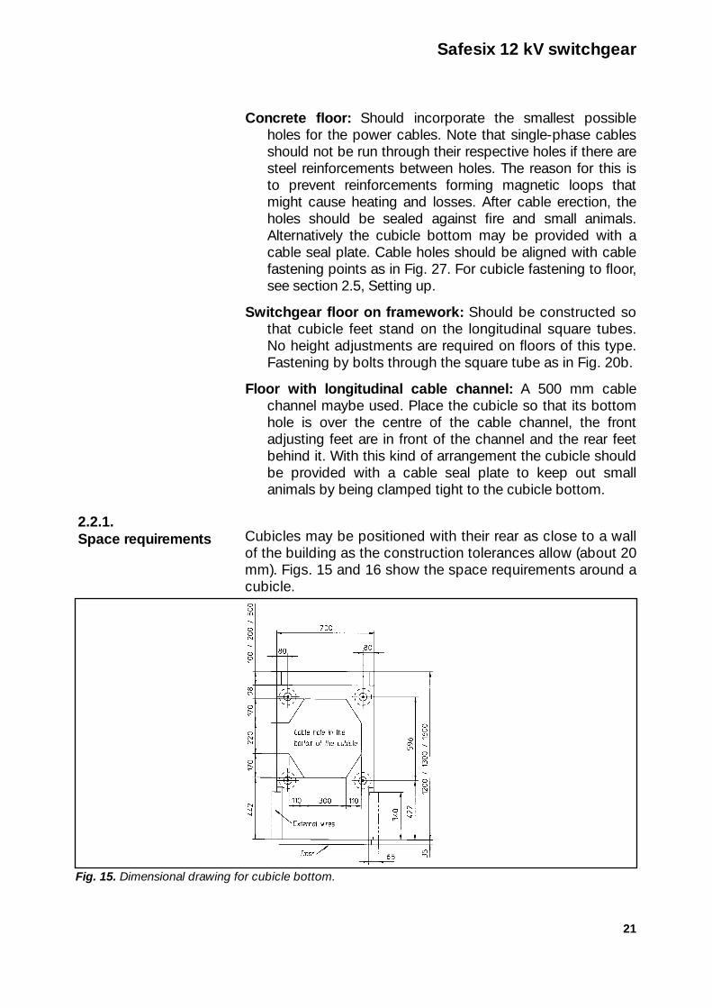
Concrete floor: Should incorporate the smallest possibleholes for the power cables. Note that single-phase cablesshould not be run through their respective holes if there aresteel reinforcements between holes. The reason for this isto prevent reinforcements forming magnetic loops thatmight cause heating and losses. After cable erection, theholes should be sealed against fire and small animals.Alternatively the cubicle bottom may be provided with acable seal plate. Cable holes should be aligned with cablefastening points as in Fig. 27. For cubicle fastening to floor,see section 2.5, Setting up.
Switchgear floor on framework: Should be constructed sothat cubicle feet stand on the longitudinal square tubes.No height adjustments are required on floors of this type.Fastening by bolts through the square tube as in Fig. 20b.
Floor with longitudinal cable channel: A 500 mm cablechannel maybe used. Place the cubicle so that its bottomhole is over the centre of the cable channel, the frontadjusting feet are in front of the channel and the rear feetbehind it. With this kind of arrangement the cubicle shouldbe provided with a cable seal plate to keep out smallanimals by being clamped tight to the cubicle bottom.
Cubicles may be positioned with their rear as close to a wallof the building as the construction tolerances allow (about 20mm). Figs. 15 and 16 show the space requirements around acubicle.
2.2.1.Space requirements
Safesix 12 kV switchgear
Fig. 15. Dimensional drawing for cubicle bottom.

22 Safesix 12 kV
switchg
ear
Fig. 16.S
pace req
uirements for S
afesix switchgear.
Right-hand end cover w
ith earthing switch on busbar
Sw
itchgear with end covers
Circuit breaker door folded out min 2650
min 1500
710
min 4
50
70
07
00
65
65
65
65
min 1
50
min 1
50
min 1
50
40
0
Right-hand end cover w
ithout earthing switch
N.B. According to SS 4362101 and the Electrical Safety Authority's heavycurrent regulations (ELSAK-FS 1994:7), if there is another row of switchgearopposite, the space between the cubicle fronts must be at least 1920 mm.

23
Cubicles are supplied wrapped in plastic, banded to palletsor packed in boxes. Withdrawable units are locked indisconnected position inside their cubicle. The easiest wayto unload cubicles is by fork truck. If they are unloaded bycrane, the four lifting eyes should be used (see Fig. 17).
Check that there is no transport damage.
If the transport protection was broken duringloading, the cubicle enclosure will have sharp edges on thesides and top. Be particularly careful when handling or touch-ing these areas.
Keep cubicle packaging as long as possible. Use a palletlifter to remove the cubicle from the shipping pallet by insert-ing it in the cubicle and placing two lifting yokes as in Fig.18. The cubicle can only be transported in this way with the
CAUTION!2.4.Moving in
2.3.Unloading
Safesix 12 kV switchgear
Fig. 18. Pallet lifter positioning.
Fig. 17. The lifting weight of cubicles is normally 400-600 kg.
Lifting tackle
24
circuit breaker removed.Before inserting the pallet lifter in the cubicle, lift off the
lower door and keep it well protected during the erectionperiod, e.g. on a pallet. The measuring transformer unit issized for possible use as a rear yoke.
If the cubicle cannot be transported upright, e.g.because of doorways being too low, it may be placed on itsback on a pallet and carried by pallet lifter to the erection site.Remove the withdrawable unit before placing the cubicle onits back.
Keep in mind the risk of pinching or injurybetween doorways and equipment and between trucks andequipment. To remove the withdrawable unit, place the select-or in position 2 (removal onto door). The unit is thus releasedand can be rolled out onto the door. This may be done withthe cubicle standing on a pallet.
Only in the lowered position should a unit becarried by lift truck. Do not leave it in the raised position on thetruck. The safest way to run a lift truck carrying a withdraw-able unit is in the lowered position.
Roof panels and busbars are supplied packed separately in therespective cubicle. Check the materials sent with them againstthe accompanying specification. Complaints about missing ordamaged items must be raised as soon as possible.
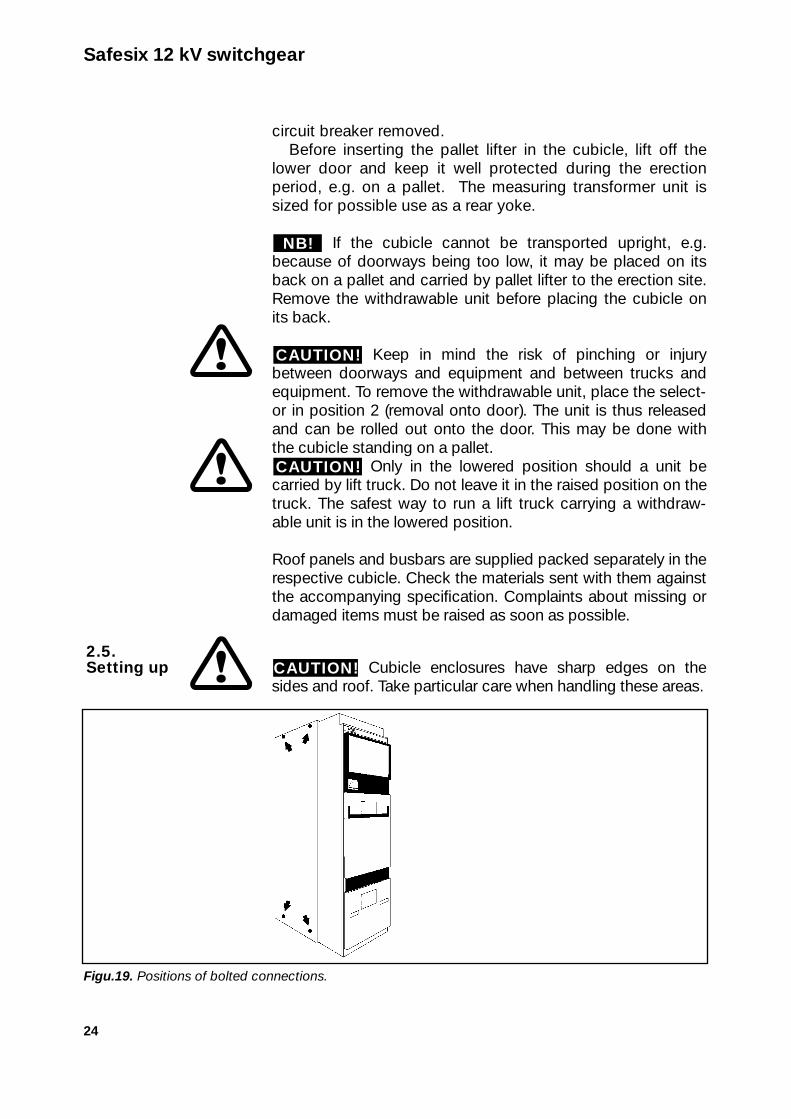
Cubicle enclosures have sharp edges on thesides and roof. Take particular care when handling these areas.CAUTION!
2.5.Setting up
CAUTION!
CAUTION!
NB!
Safesix 12 kV switchgear
Figu.19. Positions of bolted connections.
25
Setting up commences with the cubicle standing on thehighest part of the floor. Use the four adjusting screws asnecessary to adjust the cubicle to the correct level (this doesnot apply to switchgear floors with framework). Check thedistance between the set-up cubicle and sidewalls (distance =number of cubicle widths + side arrangements) as in Fig. 16. Ifthe cubicle is to stand with its rear against a wall, check that allthe screws in the rear panel are tightened before positioningthe cubicle against the wall. Place the next cubicle and adjustto the correct position. See that its front is in line with the firstcubicle. Bolt the cubicles together with four M8x16 as per Fig.19.
Fasten cubicles to the floor as per Figs. 20a and 20b. In a rowof up to four cubicles, fasten only the outer ones. Where thereare more than four, fasten every third.
Drill holes in the floor, using the square holes of the adjustingscrews as jigs. For Hilti HKDM10 type expanders drill todiameter 12, depth 50. Washers should be used (see Fig. 20a).
The bellows for control lines between cubicles is permanentlymounted on the lefthand side of each cubicle and should beinserted in the respective hole in the cubicle to the left (multi-pole contacts with bellows are optional).For erection of busbars, see section 2.6.
Erect the other cubicles in the row by the same procedure.
Beware the risk of pinching when closingdoors. When all the cubicles in the row have been set up,check that their fronts are in line and that their doors andlocking devices function properly. It is important that thedoors be closed and the handles folded into them inorder that they should withstand the pressure caused byany arcing fault. The handles should be easy to operate.Check the movement of the withdrawable units by shiftingthem from door to operating position and back.
Adjust the threshold in each cubicle downwards towards thefloor.
When handling an upper door, the handle should be graspedwith both hands. To open an upper door, raise the handle andthe door will fold out downwards. To close it, raise the handleand close the door, then press the handle down against the
CAUTION!
Safesix 12 kV switchgear

26
door panel. To open a lower door, pull the handles out towardsyou, then turn them upwards. The door will move upwards andoutwards. To close the lower door, fold the handles out fromthe door and turn them upwards. Use the guide pins on thedoor to raise it into position, then press the door downwards,turn the handles downwards and fold them in.
The gap between cubicle front side-panels is a nominal 3 mmand should not be reduced, as cubicles are tight together inmiddle part.
Safesix 12 kV switchgear
Fig. 20a. Cubicle fastening to concrete floor. Fig. 20b. Cubicle fastening to"switchgear floor".
Use a small-diameterhose to blow drillcuttings away
Hilti type expander

27
Cubicle enclosures have sharp edges on theirsides and roof. Be particularly careful when handling theseareas.
Supplied with busbars mounted on their insulators and tiltedso as not to protrude from the sides of cubicles. Torquing asper section 2.11.
2.6.1.Light series
CAUTION!2.6.Fitting busbars
Safesix 12 kV switchgear
Fig. 21. Fitting light-series busbars and droppers.
Right-hand outer cubicle
Right-hand outer cubicle
Rear
Fitting busbars and droppers
Fitting busbars
Intermediatecubicle
Intermediatecubicle
A - A
B - B B - B B - B
A - A A - A A - A A - A
Left-hand outer cubicle
View from rear
Busbars forsectioning cubicle,as seen from above
Busbars for:Droppers for:
Busbars for:
1250, 1600 A
1250, 1600 A
1250, 1600 A
800 A
1250, 1600 A
630 A
800 A
630, 800 A
630 A
630 A
1250, 1600 A 800 A 630 A
Front

Delivered with busbars mounted against the panel in thebusbar compartment. Torquing as per section 2.11.
Shipping screws must be removed from switch-gear before energisation.
The black plastic shipping interlay is intended to facilitatebusbar fitting and should be removed.
Fit these busbars in each cubicle as it is set up. Boltingtogether and torquing in the case of outer cubicles andduring retightening should be carried out from above.
CAUTION!
2.6.2.Heavy series
28
Safesix 12 kV switchgear
Fig. 22a. Fitting heavy-series busbars and droppers.
Busbars 2500 - 3150 ADroppers 2500 - 3150 A
Busbars 2500 - 3150 ADroppers 1600 - 2000 A
Busbars 2500 - 3150 ADroppers 800 - 1250 A
Intermediate cubicle Outer cubicle
Intermediate cubicle Outer cubicle
Outer cubicleIntermediate cubicle
29
Safesix 12 kV switchgear
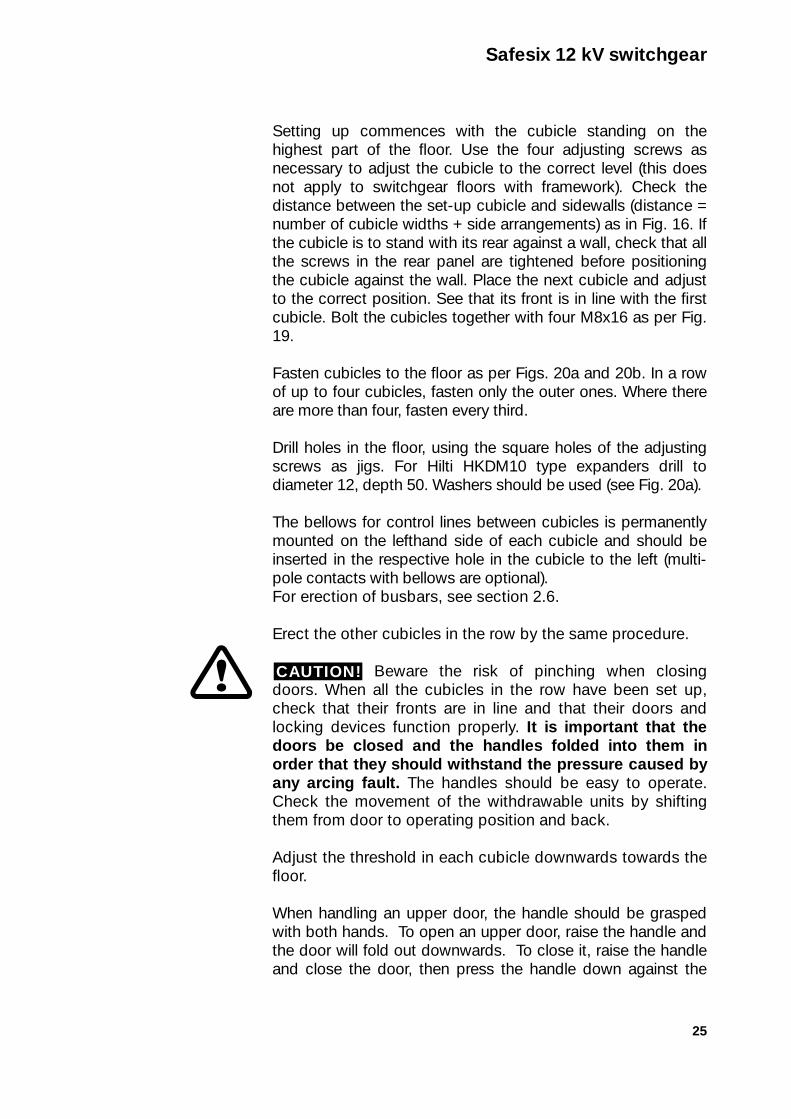
Fig. 22b. Fitting heavy-series busbars and droppers.
Busbars 1600 - 2000 ADroppers 1600 - 2000 A
Busbars 1600 - 2000 ADroppers 800 - 1250 A
Intermediate cubicle Outer cubicle
Outer cubicleIntermediate cubicle
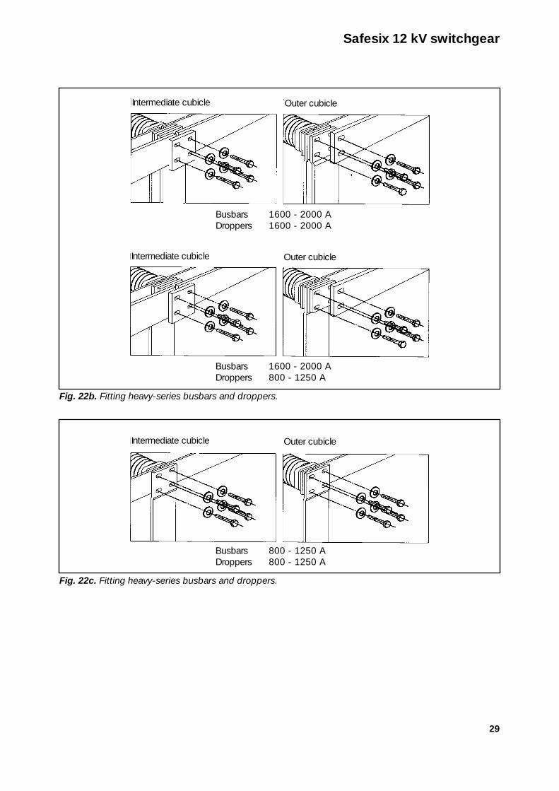
Fig. 22c. Fitting heavy-series busbars and droppers.
Busbars 800 - 1250 ADroppers 800 - 1250 A
Outer cubicleIntermediate cubicle

Cubicle enclosures have sharp edges on theirsides and roof. Be particularly careful when handling theseareas.
In the case of cubicles with single earth bars, connect anexternal earth cable to each cubicle as in Fig. 23. Make theconnection either with a spare loop or with a cable lug and anM10 bolt in the hole in the copper bar.
In the case of cubicles with earth bars running right through,link the bars up as in Fig. 24. Make sure that the bushingsbetween cubicles seat properly. Only connect the externalearth cable to the outer cubicles in the row, following the pro-cedure described above.
Copper bars connected directly to Aluzink panels shouldbe lubricated in with grease "G" (see section 6.2, Lubricants)as protection against galvanic corrosion.
CAUTION!2.7.Cubicle and system earthing
30
Safesix 12 kV switchgear
Fig. 24. Through earth bar.
Fig. 23. Single earth bar

31
Cubicle enclosures have sharp edges on theirsides and roof. Be particularly careful when handling theseareas.
Roof panels are supplied in cartons placed in therespective cubicles.
To prevent pressure relief via front doors on theoccasion of any arcing faults, roof panels must be fitted asfollows:
Panels made of 0.7 mm Aluzink sheet should be fitted fromabove and fastened at the front edge with bolts and clampingsections. The rear edge should only be fastened with plasticrivets so as to allow the pressure due to any arcing fault to bereliefed by the rivets at the rear edge sliding and the rear edgeof the panel bending upwards. The position of the front edge ofthe panel will remain unchanged.
Cubicle enclosures have sharp edges on theirsides and roof. Be particularly careful when handling theseareas.
Connect incoming/outgoing cables in the cable compart-ment. There are facilities for connecting up to six parallel single-phase cables, depending on the rated current. Before connect-ing power cables, remove withdrawable units, racking mechan-ism and doors. The PC partition may remain in place, it is trans-parent. When working on cable connections, the fitter may sit inthe cable cell or on the threshold.
If space allows, the rear panel may be removed, using along-handled socket wrench.
Connection facilities depend on rated current and cubicletype (Fig. 27 shows a standard selection).
Cable connection procedure:
1. Remove withdrawable units.See section 5.1.3.
2. Remove doors.Release the hinge pins by turning the screws through 90°as per instructions on the door. Release the swivel armson the upper door. Fold the door upwards about 15° andlift it out obliquely upwards.
CAUTION!2.9.Connectingpower cables
CAUTION!
CAUTION!2.8.Fitting roofpanels
Safesix 12 kV switchgear

32
3. Remove racking mechanism.This is done by slackening the bolts arrowed in Fig. 25.Pull the racking mechanism straight out.
4. Remove voltage transformers (option).If the cubicle has a set of voltage transformers, two screws atthe front edge have to be slackened. Pull the set out as far asit will go. Release the safety screws on the guides. Theadaptor can then be removed, using a trolley (see section2.1.1).
5. Remove lower PC partition.For good access, remove also the lower PC partition afterslackening the screws all round.
6. Run the cable upwards into the cubicle.
7. Terminate the cable as per manufacturer's instructions.Make sure that the cable screen reaches the
earth bar. Where necessary, insert earth line with at leastthe same cross-section as the cable screen. Make sure thatthe clearance between the XLPE insulation and the fieldguide of cables in the same phase is at least 10 mm. Thefield guides on all three phases must be at the same heightif they are close to one another.
8. Run cable up through cable current transformer (option).If necessary, this transformer may be loosened from its
CAUTION!
Safesix 12 kV switchgear
Fig. 25. Racking mechanism bolts.

33
mounting. Note how the transformer has to be positionedin relation to the cable (see Fig. 26). The earth conductorhas to be run back insulated through the transformer. Thetransformer mounting is adjustable relative to the cable.
9. Contact-press the cable lugs and connect.If cupped spring washers are used on bolted connections,apply torque as per section 2.11, otherwise M12 con-nections should be tightened at 80 Nm.
10. Use suitable clips to straighten and destress the cable.For example, use cable clips type UKR 90, order no.E0702971. Fasten with available bolts and nuts (see Fig.26). Cable positions are illustrated in floor plan in Fig. 15and connection points in Fig. 27.
11. Apply transparent protective flexible tubing to screen con-nections.Connect the screen to the earth bar of the cubicle.
Safesix 12 kV switchgear
Fig. 26. Fitting a cable current transformer.
Cable clip type UKR 90
Insulated earth conductor

34
Safesix 12 kV switchgear
Fig. 27. Safesix 12 kV cable fastening points.
800 A
Circuitbreakercubicle
800 A
Circuitbreakercubicle
1250 A
Circuitbreakercubicle
1600 A
Circuitbreakercubicle
2000 A
Circuitbreakercubicle
2500 A
Circuitbreakercubicle
3150 A
Cablecubicle
IHBF 12 A
Primaryreconnect-ablePosition 1
Currenttransformer
Cables Cable lugs Pattern Holes
IHBF 12 A
Primaryreconnect-ablePosition 1
IHBF 12 A
Primaryreconnect-ablePosition 2
DIN-TRAFO
Primary notreconnect-ablePosition 2
DIN-TRAFO
Primary notreconnect-ablePosition 3
DIN-TRAFO
Primary notreconnect-ablePosition 3
DIN-TRAFO
Primary notreconnect-able
1 x 3 phase150-300 mm2 D=13 — 18
D=13 — 18
D=13
32
2 x 3 phase150-300 mm2
4 x 3 phase300 mm2
4 x 1 core500-630 mm2
4 x 3 phase300 mm2
4 x 1 core500-630 mm2
6 x 1 core500-1000 mm2
6 x 1 core500-1000 mm2
6 x 1 core500-1000 mm2
663 from front
663 from front
65 720
805
from
floo
r
713
9066
390
645
90
9090
90
75
7548
0
9090
90
75
7548
0
9090
90
7575
480
645
805
from
floo
r77
2
65 720
692
65 700
622
65
65
700
630
562
769
35
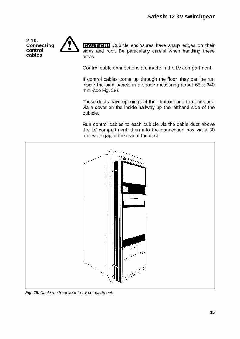
Cubicle enclosures have sharp edges on theirsides and roof. Be particularly careful when handling theseareas.
Control cable connections are made in the LV compartment.
If control cables come up through the floor, they can be runinside the side panels in a space measuring about 65 x 340mm (see Fig. 28).
These ducts have openings at their bottom and top ends andvia a cover on the inside halfway up the lefthand side of thecubicle.
Run control cables to each cubicle via the cable duct abovethe LV compartment, then into the connection box via a 30mm wide gap at the rear of the duct.
CAUTION!2.10.Connectingcontrol cables
Safesix 12 kV switchgear
Fig. 28. Cable run from floor to LV compartment.

36
Control cables may also be run from the basement beneaththe switchgear up into each cubicle division in which there is aduct (external lines) (see Fig. 15).
In the LV compartment, run the cables to the group of terminalblocks to which most of the strands are to be connected. Usestripe to fasten the cables to the fixed bars situated at therear, and fasten any protection conductors to overhead earthbars (see Fig. 29).
An option for making linking connections between cubicles isto use a connector which includes a fixed element situated onthe lefthand side of the LV compartment and mounted in abellows, while its movable element is situated in the cubicle tothe left and has to be inserted in the bellows and screwed tothe fixed element with a centre screw.
Safesix 12 kV switchgear
Fig. 29. Connecting control cables.
Terminal blocks forcurrent measurement
Terminal blocks forrelay protection
Cubicle lighting
Cable duct
Sliding terminalblocks
Terminal blocks forcontrol voltage
Terminal blocks forcubicle lighting
Terminal blocks forvoltage measurement
Terminal blocks forauxiliary contactsand earthing switch

37
Cubicle enclosures have sharp edges on theirsides and roof. Be particularly careful when handling theseareas.
The final step in cubicle erection is to check the primary currentpaths. The post-tightening of bolts on busbar connections re-quires the following torques to an accuracy of + 10%. Theyapply in cases where the spring washers that form part of thesupply are used.
M8 M10 M12 M16Nm dry 15 30 60 120Nm lubricated 10 20 40 80
If washers of some other kind are used, e.g. in the erection ofpower cables, larger torques have to be applied. In suchcases the torque for M12 connections is 80 Nm in the drystate.
Connections at voltage transformer terminals and atother terminals that have brass threads potted in epoxy shouldonly be subjected to the following torques:
M8 M10 M12 M16Nm 10 20 35 75
When all erection work has been completed,clean the cubicles thoroughly. Wipe clean all insulators,measuring transformers and screens.
IMPORTANT!
N.B.
CAUTION!2.11.Post-tightening of busbar
Safesix 12 kV switchgear

38
3Functional testing
Only servicing personnel are allowed to open cubicle doors.The following points are to be checked before commissioningswitchgear:
DANGER TO PERSONNEL 1. While switchgear is being worked on, it must be earthed to
eliminate any risk of its being energised by mistake. When operating the earthing switch, no-one
must be in the cubicle, to avoid the risk of being pinched bythe switch. Effect earthing by closing the earthing switchand connecting the temporary earthing to a through earthbar or to each cubicle separately.
Only during phase identification and insulation testingmay the temporary earthing be temporarily removed.
For safety measures before and after energisation, see ABBpublications 1WAT 910034-031 and 1WAT 910034-051.
In some cases the earthing switch is electrically interlockedso that if there is no control voltage the contact cannot bereleased.
2. Unfasten and disconnect connected power cables.
3. Check the phase identify of the busbars.Connect a battery box as follows:Earth: - 0 VL1 - 4.5 VL2 - 9 VL3 - 13.5 V
Check in every cubicle that the voltages measured on thevarious busbars are correct.
Busbar positioning in ABB indoor switchgear is as follows:a) From top to bottom: L1, L2, L3
b) From left to right: L1, L2, L3
Note: A diagram is provided in cases where any otherphase sequence is used.
4. Check the following on all withdrawable units:
CAUTION!
CAUTION!
Safesix 12 kV switchgear

39
a) that the busbar main contacts engage the connectionbars properly, minimum overlap 17 mm (see Fig. 34)
b) that the units are in the correct cubicles
c) that the interlocks work
d) that there are control voltages to the units and thatcontrol can be exercised
e) that local control works when the selector is on[DISCONNECTED] and the unit is in disconnectedposition
f) that the emergency trip works in operating position
g) that a closed circuit breaker cannot be run into ortaken out of service position
h) that the sliding contacts are undamaged
5. Insulation test. Use a megger to measure the switchgearinsulation resistance.
Before doing so, check:– that all voltage transformer primaries are disconnected
– that any surge arrestors are disconnected
– that all current transformer secondary circuits areclosed
In cases where switchgear is not subjected to a HV test,the insulation resistance should be measured with a 5 kVmegger. In other cases a 1 kV or 0.5 kV megger will suffice.
Measure insulation resistance as follows:a) L1 - , L2 - , L3 - b) L1 - L2, L2 - L3, L3 - L1
Measured insulation values should amount to at least 1Mohm per kV of rated voltage of the switchgear.
6. Reconnect the power cables and the components dis-connected in item 5 above. Apply correct torque to allconnections that have been slackened.
7. In the case of units with fuses, check on the equipmentlist that all the high-power fuses tally.
8. Check the settings of all relays against the installationdocumentation.
N.B.
Safesix 12 kV switchgear

40
9. Check control circuits in all cubicles against the installationdocumentation.
10. Check the control circuit transitions between cubicles.
11. Check that all screws on terminal blocks are tight andthat no insulation is pinched.
12. Check that units cannot be connected in bays intendedfor ones with a higher rated current. The mechanicalblocking devices must prevent any such mistakes.
13. Check that units cannot be shifted while they are closed.Where there is disconnector, check the interlock system.
14. Check that selector and racking mechanism works.
15. Check that the black bushings on through earth bars seatproperly and provide a seal between cubicles.
16. Open the earthing switch so that the indicator displayseither "0" or "OPEN".
17. Check that the doors are properly closed and the handlesfolded down/in towards the door.
Beware door pinch risk. It is important thatthe handle should be easy to fold down when the door tothe withdrawable unit cell is closed, so that the door lockwill work as intended, i.e., so as to withstand pressure dueto any arcing fault.
CAUTION!
Safesix 12 kV switchgear

41
4Commissioning
The operator access zone is the aisle in front of the switchgear.Only servicing personnel are allowed to open cubicle doors.
There is no contact protection inside the lowerdoor. The cable side must be de-energised and be earthed byclosing the earthing switch before opening the lower door.When operating the earthing switch, no-one must be in thecubicle, to avoid the risk of being pinched by the switch.Unauthorised access inside the doors may be prevented bypadlocking the handles of both the lower and upper doors.
Beware risk of being pinched when closingdoors.
Cubicle enclosures have sharp edges on theirsides and roof. Be particularly careful when handling theseareas.
Carry out functional tests as per chapter 3 and maintenancepoints as per chapter 6.1.
Carry out appropriate parts of functional tests as per chapter3 and maintenance points as per chapter 6.1.
Carry out checks as per section 3.17 and instructions as per6.1. Also maintenance as necessary.
4.3.Commissioningafter stoppage
4.2.Commissioningafter stoppage for repaire orother action
4.1.Commissioningnew switchgear
CAUTION!
CAUTION!
CAUTION!
Safesix 12 kV switchgear
CAUTION! Before taking action, follow the safety instructions on page 41.

42
5Operating instructions
The operator access zone is the aisle in front of the switchgear.Only servicing personnel are allowed to open cubicle doors.
There is no contact protection inside the lowerdoor. The cable side must be de-energised and be earthed byclosing the earthing switch before opening the lower door.When operating the earthing switch, no-one must be in thecubicle, to avoid the risk of being pinched by the switch.Unauthorised access inside the doors may be prevented bypadlocking the handles of both the lower and upper doors.
Beware risk of being pinched when closingdoors.
Cubicle enclosures have sharp edges on theirsides and roof. Be particularly careful when handling theseareas.
Interlock chain in Safesix cubicles with HPA or HA circuitbreaker. Conditions to be fulfilled to make connection possible:
1. The selector has to be in service position (position 4) or testposition (position 1). The circuit breaker interlock rod mustbe in its topmost position, use the microswitch in the"make" circuit to check that it is.
2. The control voltage must be 85-110% of nominal.
3. The circuit breaker "make" springs must be tensioned, usethe microswitch in the "make" circuit to check that they are.
Closing results in:
1. Mechanical blocking of the racking mechanism selector.
2. Links coming out on the righthand side of the circuit breakerso that the closed circuit breaker cannot shift while in serviceposition (applies to HPA).
Conditions to be fulfilled to make opening possible:
1. The circuit breaker must be closed, use auxiliary contactsto check that it is.
2. The control voltage must be 70-110% of nominal DC or85-110% of nominal AC.
5.1.Circuit breaker HPA and HA
CAUTION!
CAUTION!
CAUTION!
Safesix 12 kV switchgear
CAUTION! Before taking action, follow the safety instructions on page 41.

43
Safesix 12 kV switchgear
Mechanical opening is always possible by emergency trip onthe front of the cubicle (HPA) or by mechanical push-buttonon the front of the circuit breaker (HA), neither of which areaffected by mechanical or electrical blocking.
If the circuit breaker has an anti-pumping relay (HPA option),closing is blocked so long as the "make" pulse persists after amake/break sequence. If the circuit breaker has an under-voltage trip (option) it opens the circuit breaker if the controlvoltage falls below 70% of nominal.
The switchgear may have both manual and remote control.Remote control makes it possible to use an actuator on thecubicle front to select "local" in order to bar remote signals.The unit can then be controlled manually.
The mechanical control devices are situated below the doorto the withdrawable unit.
The control on the left is a selector that has to be placed in thecorrect position for the control operation intended.
The racking mechanism is to the right of the selector. Use thecrank to wind the withdrawable unit between the disconnected(OPEN) and service (CLOSED) positions.
On the far right is the control mechanism for the earthingswitch. Use the same crank to operate the earthing switch.The first step is to place the selector in the earthing position(1). If the earthing switch has electrical interlocking, the block-ing device to the right of the earthing switch operating holehas to be moved to the left and pressed downwards so as toopen the hole for inserting the crank. If the blocking devicecannot be pressed downwards, this is because the interlockmagnet is preventing it (is not "pulled"). This means that theswitchgear is energised and cannot be earthed before thesupply [residual supply] is disconnected. Unauthorised oper-ation of the withdrawable unit or earthing switch can beprevented by inserting a locking device in the hole and pad-locking it. The flanged half of the locking device is first in-serted far enough to become firmly fastened behind thebushing, followed by inserting the other half in the hole andpadlocking one of the three holes (see Fig. 30).
5.1.1Circuit breakershift
CAUTION! Before taking action, follow the safety instructions on page 41.

44
The procedure for placing the circuit breaker in the cubicleand shifting it to service position or disconnected position(test position) is as follows:
1. Before the circuit breaker can be placed in it, the cubiclemust be earthed, which involves turning the selector to theearthing position (Fig. 31a), thereby opening the earthingswitch operating hole. Insert the crank in the hole and windit clockwise to close the earthing switch. If there is electricalinterlocking (option), the blocking device to the right of theoperating hole has to be moved to the left and presseddownwards to free the hole.
2. Use a trolley to raise the circuit breaker. Whenusing a trolley, the unit concerned must always be carriedin the lowered position. Do not leave it in the raised positionon the truck.
3. Turn the selector to removable position (Fig. 31b), open thedoor to the circuit breaker compartment (see section 2.5 ondoor handling). Place the circuit breaker on the door so thatthe wheels are on the door rail sections. Beware the risk of being pinched by the closing door orbetween the circuit breaker and the rails. Push the circuitbreaker all the way into the cubicle and close the circuitbreaker door. The circuit breaker can be test-operated byturning the selector to the earthing position (Fig. 31a). Inthis position the circuit breaker is isolated from the busbarsystem. Remember that the LV circuits are connected.
CAUTION!
CAUTION!
5.1.2Circuit breakershift to operatingposition
Safesix 12 kV switchgear
CAUTION! Before taking action, follow the safety instructions on page 41.
Fig. 30. Locking the controls.
45
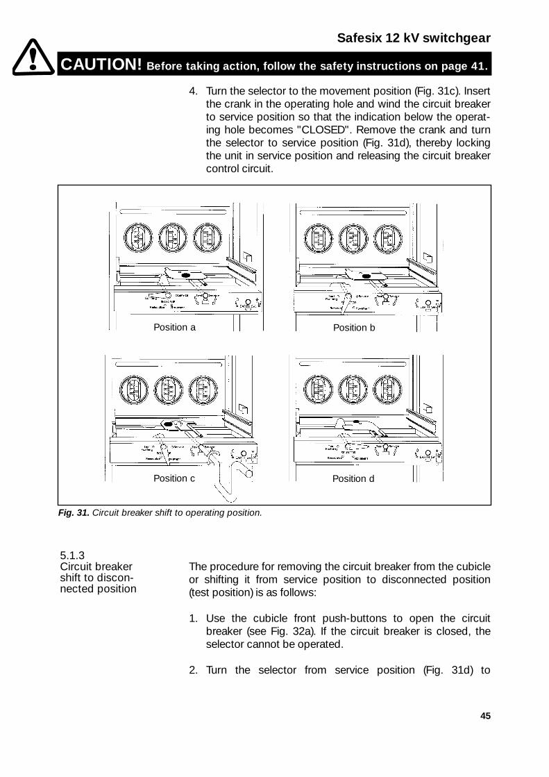
4. Turn the selector to the movement position (Fig. 31c). Insertthe crank in the operating hole and wind the circuit breakerto service position so that the indication below the operat-ing hole becomes "CLOSED". Remove the crank and turnthe selector to service position (Fig. 31d), thereby lockingthe unit in service position and releasing the circuit breakercontrol circuit.
The procedure for removing the circuit breaker from the cubicleor shifting it from service position to disconnected position(test position) is as follows:
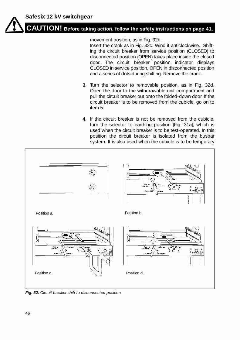
1. Use the cubicle front push-buttons to open the circuitbreaker (see Fig. 32a). If the circuit breaker is closed, theselector cannot be operated.
2. Turn the selector from service position (Fig. 31d) to
5.1.3Circuit breakershift to discon-nected position
Safesix 12 kV switchgear
CAUTION! Before taking action, follow the safety instructions on page 41.
Fig. 31. Circuit breaker shift to operating position.
Position a Position b
Position dPosition c
46
movement position, as in Fig. 32b.Insert the crank as in Fig. 32c. Wind it anticlockwise. Shift-ing the circuit breaker from service position (CLOSED) todisconnected position (OPEN) takes place inside the closeddoor. The circuit breaker position indicator displaysCLOSED in service position, OPEN in disconnected positionand a series of dots during shifting. Remove the crank.
3. Turn the selector to removable position, as in Fig. 32d.Open the door to the withdrawable unit compartment andpull the circuit breaker out onto the folded-down door. If thecircuit breaker is to be removed from the cubicle, go on toitem 5.
4. If the circuit breaker is not be removed from the cubicle,turn the selector to earthing position (Fig. 31a), which isused when the circuit breaker is to be test-operated. In thisposition the circuit breaker is isolated from the busbarsystem. It is also used when the cubicle is to be temporary
Safesix 12 kV switchgear
CAUTION! Before taking action, follow the safety instructions on page 41.
Fig. 32. Circuit breaker shift to disconnected position.
Position a. Position b.
Position d.Position c.
47
earthed. If there is risk of residual voltage in the cubicle, theearthing switch should be provided with an interlockmagnet. When the selector is in position test/earthing, theearthing switch can be closed, thereby earthing the cableside, but remember that the LV circuits are not affected.
When the earthing switch is closed, the selector isblocked. The indicator may display or CLOSED.
5. Take the circuit breaker trolley away. Whenusing a trolley, the unit concerned must always be carried inthe lowered position. Do not leave it in a raised position onthe trolley. Pump the lifting cradle on the trolley up so thatthe lifting lugs on both sides of the circuit breaker fit into therecesses on the cradle. Then pump the cradle still higher sothat the circuit breaker can be removed from the door.
When it is outside the cubicle, it is only possible to switchthe switch disconnector on and off if it is on the upper dooror there is at least 20 mm clearance between its bottompanel and the support.
Conditions to be fulfilled before the unit can be switchedon:
SFL inside the cubicle:— Selector to be in service position (Fig. 31d) or test
position (Fig. 31a).— Operating device to be tensioned manually by control
lever.
SFL outside the cubicle:— The slide on the bottom panel must be in its extreme left or
right position to permit movement of the interlock rod in-side the righthand side panel of the SFL frame. The slide isnormally actuated by the selector when the unit is in thecubicle but has to be actuated manually when the unit isout.
1. The interlock rod prevents a unit that is closed being pushed into the cubicle from the door.
2. A unit that is closed cannot be shifted from test position toservice position.
3. The unit cannot be closed while being shifted.
5.2.1Safesix interlockchain for SFL
5.2.Switch discon-nector SFL
CAUTION!
Safesix 12 kV switchgear
CAUTION! Before taking action, follow the safety instructions on page 41.

48
4. Mechanical interlocking prevents rotation of the selectorif the unit is closed.
5. Mechanical blocking of the racking mechanism selector pre-vents a closed unit being withdrawn from service position.
6. It is not possible to close the earthing switch if SFL is inservice position or being shifted.
SFL is shifted in the same way as shifting a circuit breaker,as described in Chapter 5, which also describes the oper-ation and functions of the racking mechanism.
The procedure for placing SFL in the cubicle and shifting it toservice position or disconnected position (test position) is asfollows:
1. Check that the cubicle is earthed before SFL is placed in it.Earthing involves using the built-in earthing switch, the po-sition of which is shown by an indicator on the cubicle frontor can be viewed through the window in the lower door.The first step is to turn the selector to the earthing position(Fig. 31a), thereby opening the earthing switch operatinghole. Insert the crank in the hole and wind clockwise untilthe earthing switch closes. If there is electrical interlocking(option) the blocking device to the right of the hole has tobe moved to the left and pressed downwards to free thehole.
2. Use a trolley to raise SFL. When using atrolley, the unit concerned must always be carried in thelowered position. Do not leave it on the trolley in the raisedposition.
3. Check that the slide on the SFL frame bottom panel is inthe central position (torsion spring untensioned). Turn theselector to removable position (Fig 31b) and open the doorto the withdrawable unit compartment.
Open the door by grasping the black horizontal handlewith both hands and turning it upwards, thereby releasingthe locking devices so that the door can fold outwards to ahorizontal position in which its dimensioning enables it totake the weight of the withdrawable unit. Place SFL on thedoor so that its wheels are on the door rail sections.
CAUTION!
5.2.3.Shifting switchdisconnector SFL toservice position
5.2.2.Shifting switchdisconnector SFL
Safesix 12 kV switchgear
CAUTION! Before taking action, follow the safety instructions on page 41.

49
Beware the risk of pinching as the doorcloses or between SFL and the door rails. Push SFL all theway into the cubicle, fold its handle upwards, close thedoor to the withdrawable unit compartment and fold thedoor handle downwards. Beware the risk ofinjury caused by arcing fault. It is important that the doorshould be closed properly so as to prevent injury due toany arcing fault. When the door closes, the handle shouldbe easy to slide down against the door panel.
4. Turn the selector to test/earthing position (Fig. 31a). SFLcan be tested in this position, in which it is disconnectedfrom the main circuit. The auxiliary circuit remainsconnected.
In this position it is also possible to use the earthingswitch to earth the cable side temporary.
5. To put SFL into service position, disconnect the earthingswitch by inserting the crank in the operating hole andwinding it anticlockwise until the earthing switch opens.The indicator below the operating hole will display "0" or"OPEN". Turn the selector to movement position (Fig.31c),insert the crank in the racking mechanism operating holeand wind SFL to service position. The indicator below theoperating hole will then display "CLOSED". Remove thecrank and turn the selector to service position (Fig.31d),thereby locking a cam on the selector shaft the unit inservice position.
The door to the withdrawable unit compartment should beclosed when SFL is being operated. Take the control lever andopen the operating hole cover on the door. Insert the controllever and make sure that it goes into the socket grip on theSFL control shaft. Tension the springs of the operating deviceby turning the control lever clockwise until you hear a click orreach the stop. To switch the switch disconnector on, turn thecontrol lever anticlockwise until the unit is closed (the torquerequired is 80-100 Nm). Interlocks prevent rotation of theselector so long as SFL is closed.
The procedure for removing switch disconnector SFL from thecubicle or shifting it from service position to disconnectedposition (test position) is as follows:
5.2.5.Shifting switchdisconnector SFL todisconnected position
5.2.4.Switching switchdisconnector on
N.B.
CAUTION!
CAUTION!
Safesix 12 kV switchgear
CAUTION! Before taking action, follow the safety instructions on page 41.

50
There may be both manual and remote control of theswitchgear. Remote control makes it possible to change overto manual control by turning the actuator on the cubicle front tothe "local" position.
1. For manual switching off, take the control lever and openthe operating hole cover in the upper door. Insert thecontrol lever and make sure that it goes into the socket gripon the SFL control shaft. Turn it clockwise until the unit isswitched off. Only slight rotation is required. Remove thecontrol lever.
The switch disconnector may be provided with a discon-necting magnet for remote tripping. The auxiliary voltagemust be 70-110% DC or 85-110% AC of nominal. Theinterlock of the selector drops out when SFL is switchedoff.
2. Turn the selector to movement position (Fig 32b), insert thecrank in the racking mechanism operating hole and shiftSFL to disconnected position by winding the crank anti-clockwise. The indicator below the operating hole will dis-play "OPEN". Remove the crank.
3. Turn the selector to test/earthing position (Fig 31a). In thisposition it is possible to test-operate SFL, which is nowdisconnected from the main circuit. Remember thatthe auxiliary circuit is still connected. It is also possible inthis position to use the earthing switch to earth the cableside temporary.
4. To remove SFL from the cubicle, close the earthing switch.The indicator will display or "CLOSED". Turn the select-or to removable position (Fig.31b), open the door to thewithdrawable unit compartment, fold out the handle of SFLand pull the unit out all the way onto the open door.
5. Use a trolley to raise SFL and lift it down from the doorWhen using a trolley, the unit concerned must
always be carried in the lowered position. Do not leave it inthe raised position on the trolley. To avoid damageto SFL, it must be switched off (indicator displaying 0)before being placed on a level support, otherwise there hasto be at least 20 mm clearance between the bottom paneland the support.
N.B.
CAUTION!
N.B.
5.2.6.Switching switchdisconnector off
Safesix 12 kV switchgear
CAUTION! Before taking action, follow the safety instructions on page 41.

51
Interlock chain for Safesix cubicles with NAL 12/630, NALF12/630.Conditions to be fulfilled for switching on to be possible:
1. Selector to be in service position.
2. Control lever to be inserted manually and operatingdevice tensioned before the unit can be switched on.
Switching on results in:
1. Mechanical blocking of the racking mechanism selector,prevents a closed unit being withdrawn from serviceposition.
2. The interlock fork situated on the left under the frontcover of the switch disconnector preventing the unitbeing pushed into the cubicle (see Fig. 33d).
Conditions to be fulfilled for switching off to be possible:
1. Switch disconnector to be closed, use auxiliary contacts tocheck that it is.
5.3.Switch disconnectors NAL 12/630, NALF 12/630
Safesix 12 kV switchgear
Fig. 33. Shifting and operating NAL/NALF.
33 a.
Switching on
Switching off
33 d.
33 c.
33 b.
CAUTION! Before taking action, follow the safety instructions on page 41.

52
2. For manual switching off the control lever has to be in-serted in the operating hole. With a switched off magnet(option) the switch disconnector can be switched off elect-rically, in which case the control voltage has to be 70-110% DC nominal or 85-110% AC nominal.
The switchgear may have both manual and remote control.Remote control makes it possible to use an actuator on thecubicle front to select "local" in order to bar remote signals.The unit can then be controlled manually.
The cubicle must be de-energised when theswitch disconnector is pushed into it, since connection to theprimary circuit takes place when the door is open.
1. Move the interlock fork to its righthand position (see Fig.33d) and push the switch disconnector into the cubicle.
2. Close the door.
3. Turn the selector from test/earthing position to service as inFig. 33a.
4. Use the control lever to switch on the switch disconnector(see Fig. 33b). At the same time, the selector will be lockedso that it cannot be turned from the service position. Thefirst step in making it possible to switch on is to tension theoperating device by turning the lever clockwise all the way.The unit is then switched on by turning the handle anti-clockwise until the unit is switched on. Remove the handleand place the masking disc over the operating hole, whichcan then be padlocked.
5. Switching off involves inserting the control lever in theoperating hole and turning it clockwise (see Fig. 33b).
Earthing1. Switch off the switch disconnector (see Fig. 33b). Its posit-
ion can be viewed through the window in the door.
2. Move the selector from service position to test/earthingposition as in Fig. 33c. The switch disconnector can nowbe pulled out onto the door, e.g. for fuse replacement.
3. Crank the earthing switch to closed position (indicatordisplaying ), and at the same time lock the selector toprevent its being moved to service position.
Test operation of switch disconnector on door.
CAUTION!5.3.1.Operating NAL/NALF
Safesix 12 kV switchgear
CAUTION! Before taking action, follow the safety instructions on page 41.

53
Beware the risk of being injured during operationof the switch disconnector, which has accessible open knives.
1. Move the interlock fork on the left under the front cover ofthe switch disconnector to the lefthand position (see Fig.33d). In this position the fork prevents the switchdisconnector being pushed into the cubicle while at thesame time allowing the unit to be operated.
2. Switch the switch disconnector on (see Fig. 33b) as peritem 4 under "Operating NAL/NALF".
Beware risk of accident due to switchdisconnector knives.
3. Switch the switch disconnector off (see Fig. 33b) as peritem 5 under "Operating NAL/NALF ".
4. Move the interlock fork to its upper position. The switchdisconnector can then be pushed into the cubicle.
CAUTION!
CAUTION!
Safesix 12 kV switchgear
CAUTION! Before taking action, follow the safety instructions on page 41.

6Maintenancerules
The operator access zone is the aisle in front of the switchgear.Only servicing personnel are allowed to open cubicle doors.
There is no contact protection inside the lowerdoor. The cable side must be de-energised and be earthed byclosing the earthing switch before opening the lower door.When operating the earthing switch, no-one must be in thecubicle, to avoid the risk of being pinched by the switch.Unauthorised access inside the doors may be prevented bypadlocking the handles of both the lower and the upper door.
Beware risk of being pinched when closingdoors.
Cubicle enclosures have sharp edges on theirsides and roof. Be particularly careful when handling theseareas.
Switchgear maintenance comprises inspection and cleaningas per Table 6.1.
The maintenance intervals shown apply to normal environ-ments and have to be shortened as necessary to cater forseverer conditions. Suitable times for undertaking maintenanceinclude when switchgear is taken out of operation to allowextension work or is de-energised for other reasons.
The tool requirement is a normal set of tools for electricalmaintenance work and the special tools indicated in Chapter 7.
For circuit breaker maintenance, see separate manual.
Certain operations that require switchgear to becompletely de-energised and earthed for work are marked in Table 6.1. Other operations that can be carried out withswitchgear energised are marked . Work under voltage isgoverned by safety rules according to ESA. Operations marked
can be carried out both under voltage and/or when thecubicle is temporary earthed.
CAUTION!
CAUTION!
CAUTION!
CAUTION!
54
Safesix 12 kV switchgear

6.1.Switchgear cubiclemaintenance
55
Safesix 12 kV switchgear
Before com-missioning andafter 1 year
Maintenance intervals
Every 5 years
Inspection/action
Dust and vacuum clean the following surfaces:
1. Shielding and PC partitions (partitions may be removed in severely fouled cubicles to gain access to spaces behind them).Treat PC partitions with Plexiklar or AntistatischerKunststoffreiniger und Pfleger to prevent static electricity.
Do not use other solvents such as acetone,ammonia, ether, methanol, trichloroethylene or the like, as theywould damage the polycarbonate (spontaneous cracking).
2. Insulators
3. Measuring transformers
4. Cables and connections
Beware the risk of being pinched when operatingan earthing switch. Check its function and make sure that there is fullcontact engagement in closed position . During maintenance of anearthing switch, if the grease on the silvered contacts is dry or conta-minated, remove it and apply a fresh coating of grease type G (seesection 6.2). If the grease on the worm gear is very contaminated,remove the old grease and apply a fresh coating of grease type E.Check the state of the spring and operate it. Lubricate the bearingsof control shafts and indicator spindles with oil A.
Damaged painted surfaces of cubicles are to be cleaned and pain-ted with patching paint or protected from corrosion with a thin filmof grease type E.
Check that the lighting in each cubicle works.
In most cubicles, opening the lower door provi-des access to parts carrying high voltage. Check that the coolingair valves are in the open position. This applies to 1600, 2000, 2500and 3150 A cubicles.
Check that the silvered female contacts are not oxidised. If theyare, clean and lubricate with grease type G.
Inspect each cubicle visually to see that there are no damagedcomponents or conductors.
Lubricate the moving parts of running gear with oil A or grease E.Check that shielding and PC partitions are in
position.CAUTION!
CAUTION!
CAUTION!
CAUTION!
Underlinedinstructionsto be carriedout asnecessaryregardless ofordinarymaintenanceintervals
Underlinedinstructionsto be carriedout as nec-essary re-gardless ofordinarymain-tenanceintervals

56
Safesix 12 kV switchgear
1 The engagement distance should normally be 25 mm (toler-ance range 17-33 mm) as per Fig. 34. Maximum lateral dis-placement ±3 mm.
Maintenance to be done only when switchgear de-energised and temporary earthed.
Maintenance can be done with switchgear energised.
Maintenance can be done both under voltage and/orwhen cubicle temporary earthed.
Data on contacts appear in Information sheet 5216 701-V.
Check that connecting bars for withdrawable units are not oxidi-sed. If they are, clean and lubricate with a fresh coating of greasetype G.
Check that earth connections for withdrawable units are not oxidi-sed. If they are, clean and lubricate with a fresh coating of greasetype G.
Check that connecting bars of withdrawable units engageproperly1. Lubricate the contacts with a thin film of grease type G.Operate any units that have not been used for a long time, andtheir racking mechanism.
Check that the sliding contacts in the roof of the compartment forwithdrawable units are intact and run easily into one another.
Cubicle contacts are energised with auxiliary vol-tage..CAUTION!
Fig. 34. Contact engagement.
Before com-missioning andafter 1 year
Maintenance intervals
Every 5 years
Inspection/action

57
By way of guidance in choosing lubricants, the following tableshows a number of alternatives under different brands.
Only the following cleaning agents should beused on polycarbonate screens and on plexiglas, otherwisethe material will develop spontaneous cracking:
“Plexiklar" or "Antistatischer Kunststoffreiniger und Pfleger".
CAUTION!6.3.Cleaning agents
6.2.Lubricants
Safesix 12 kV switchgear
Brand
ABB no.
BP
Klüber
Mobil
OK
Q8
Shell
Statoil
Grease “E”
1171 4012-201
Energrease LS 2
Microlube GL 261
Aero Shell Grease 14
Oil “A”
1171 2013-301
Enegrol HLP 32
D.T.E. 24
Hydraulic Oil 23
Hayden 32
Tellus Oil 32
Hydraway HMA 32
O-ring grease
1171 4014-409
Barrierta L55/2
Grease “G”
1171 4014-407
Neblan
Mobile Grease 28
718 EP Shynt. grease
Aero Shell Grease 22
Uniway LYX 43

58
7Accessories, spares and ancillary equipment
Spares . . . . . . . . . . . . . . . . . . . . . . . . . . . .Order no.Microswitch . . . . . . . . . . . . . . . . . . . . . . .1VEB 537301-002Microswitch . . . . . . . . . . . . . . . . . . . . . . .1VEB 537301-003Circuit breaker sliding contact . . . . . . . . .2657 992-HCubicle sliding contact . . . . . . . . . . . . . . .2657 992-GCubicle sliding contact . . . . . . . . . . . . . . .2657 992-FLower hatch handle, right . . . . . . . . . . . . .2184 4403-ADLower hatch handle, left . . . . . . . . . . . . . .2184 4403-AEHatch hinge . . . . . . . . . . . . . . . . . . . . . . . .2184 4402-9Interlock box electromagnet . . . . . . . . . . .5254 778-XXRacking mechanism ² 1250 A . . . . . . . . . .LV 841 028-MDRacking mechanism > 1250 < 2500 A . . .LV 841 028-MCRacking mechanism 2500 A . . . . . . . . . . .LV 841 028-MERacking mechanism 3150 A . . . . . . . . . . .LV 841 028-MFEarthing switch operating arm, 31.5 kA . .2239 702-ANEarthing switch operating arm, 40 kA . . . .2239 702-APLimit switch contact . . . . . . . . . . . . . . . . .LV 841 708-XX
Each cubicle lower earth bar is provided with two bulldog gripsfor connecting earth conductors for system and cable sheathearthing. If further clips are necessary, they can be ordered asper table. The data are for clips mounted on bars 4-8 mmthick.
For mm2 lineFuse wires Fine wires RK Order no.
16-50 16-50 16-50 LV 889 031-A35-185 35-120 35-150 LV 889 031-B95-300 95-185 95-240 LV 889 031-C
Patching paintLight-beige paint. Order no. SA 263 022-VA
CrankFor cubicle front control operations. Normally included incubicle supply.Order no. 2247 953-AFor HPA circuit breaker spring tensioning:Order no. LV 899 361-A
Safesix 12 kV switchgear

59
TrolleyTo carry withdrawable units.Order no. 1VES 841 930-AAA, hydraulic variantAdaptor to carry voltage measuring sets:Order no. 1VES 841 930-AAB
Tool setTool set for switchgear with Combiflex relays. Box contains 1groove chisel, 5 RTXD extractors, 1 chisel set (Torx), 1 Poly-komb 13 mm wrench and 1 wheel for locks. Best. nr LV 899 011-G.
Groove chisel with insulated blade 240 mm long.For Ben Kri URTK/S terminal blocksOrder no. SK 176 2130
Polykomb wrench type VNPK 13For jaw width 13 mm, set of twoOrder no. SK 176 0918
Hexagon socket for cable erectionOrder no. LV 851 940-AA
Equipment available on request:
Flue gas hoodsTo guide pressure and flue gases from arcing faults directly outinto the open air without pressurising the building. To be fittedaccording to documentation specific to each order.
Arc monitorsAvailable in two versions.Standard monitor opens supply circuit breaker if onecondition is fulfilled:1. Light beam from arc
Special version requiring fulfilment of two conditions:1. Light beam from arc2. High current
Other information appears in Instruction 1SFC 16601-SV
Safesix 12 kV switchgear

60
8Documentation references
ABB publication Content
IVEB 580901-911 . . . . . . . .HPA manual
IVEB 580901-902 . . . . . . . .HA1 manual
IVEE 301701-900 . . . . . . . .SafeGuard manual
9VLB 9304-11 . . . . . . . . . . . .Tightening torque for electricalconnections made of coppe
1WAT 910034-031 . . . . . . .Indoor medium voltage switchgear
1WAT 910034-051 . . . . . . .Energizing of switchgear
5216 701-V . . . . . . . . . . . . . . . .Information on contacts
As this manual is subject to continuous updating, we wouldappreciate comments on its content being sent to the followingaddress:
ABB Switchgear Dept. MCBox 1023S-732 27 ArbogaTel: +46 589-851 00Fax: +46 589-852 90
Address for further information on servicing under guarantee:
ABB Switchgear Dept.MQGBox 1023S-732 27 ArbogaTel: +46 589-851 00Fax: +46 589-852 90
Safesix 12 kV switchgear

NOTES........................................................................................................................................................................................................................
........................................................................................................................................................................................................................
........................................................................................................................................................................................................................
........................................................................................................................................................................................................................
........................................................................................................................................................................................................................
........................................................................................................................................................................................................................
........................................................................................................................................................................................................................
........................................................................................................................................................................................................................
........................................................................................................................................................................................................................
........................................................................................................................................................................................................................
........................................................................................................................................................................................................................
........................................................................................................................................................................................................................
........................................................................................................................................................................................................................
........................................................................................................................................................................................................................
........................................................................................................................................................................................................................
........................................................................................................................................................................................................................
........................................................................................................................................................................................................................
........................................................................................................................................................................................................................
........................................................................................................................................................................................................................
........................................................................................................................................................................................................................
........................................................................................................................................................................................................................
........................................................................................................................................................................................................................
........................................................................................................................................................................................................................
........................................................................................................................................................................................................................
........................................................................................................................................................................................................................
........................................................................................................................................................................................................................