eh 175300, ek 110210, ehl 210300, ekl 150.. overload relay edition c, november 2015 installation...
TRANSCRIPT
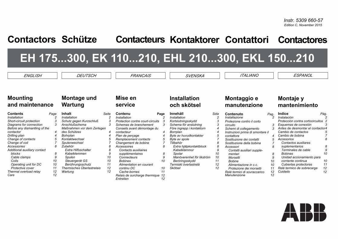
ITALIANO ESPANOLSVENSKAENGLISH DEUTSCH FRANCAIS
Contactores
Montaje ymantenimientoIndice Pág.Instalación 2Protección contra cortocircuitos 2Esquemas de conexión 3Antes de desmontar el contactor4Cambio de contactos 5Cambio de bobina 7Accesorios 8
Contactos auxiliaressuplementarios 8Terminales de cable 9Bobinas 10Unidad accionamiento paracorriente continua 10Cubiertas protectoras 11
12Relè termico de sobrecarga12Cuidado
Instr. 5309 660-57
EH 175...300, EK 110...210, EHL 210...300, EKL 150...210Contattori
Montaggio emanutenzioneContenuto Pag.Installazione 2Protezione contro il corto
3otiucricSchemi di collegamento 3Instruzioni prima di smontare il
4erottatnocSostituzione dei contatti 5Sostituzione della bobina 7
8irosseccAContatti ausiliari supple-
8iratnem9ittesroM
Bobine 10Alimentazione in c.c. 10Protezione dei morsetti 11
Relè termici di sovraccaricoManutenzione 12
Kontaktorer
Installationoch skötselInnehåll SidaInstallation 2Kortslutningsskydd 3Schema för anslutning 3Före ingrepp i kontaktorn 4
4nalprroBByte av huvudkontakter 5Byte av spole 7
8röheblliTExtra hjälpkontaktblock 8Kabelklämmor 9
01ralopSManöverenhet för likström 10Beröringsskydd 11
1212
12
Termiskt överlastreläSkötsel
Contacteurs
Mise enserviceContenu PageInstallation 2Protection contre court-circuits 3Schemas de branchement 3Conseils avant dèmontage du
4ruetcatnocPlan de perçage 4Remplacement contacts 5Changement de bobine 7Accessoires 8
Contacts auxiliairessupplémentaires 8Connecteurs 9Bobines 10Alimentation en courantcontinu DC 10Cache-bornes 11
12Relais de surcharge thermique12Entretien
Schütze
Montage undWartungInhalt SeiteInstallation 2Schutz gegen Kurzschluß 3Anschlußschema 3Maßnahmen vor dem Zerlegendes Schützes 4
4nalprhoBKontaktwechsel 5Spulenwechsel 7
8röhebuZExtra Hilfsschalter 8Kabelklemmen 9Spulen 10Steuergerät GS 10Berührungsschutz 11
12Wartung 12Thermisches Überlastrelais
Contactors
Mountingand maintenanceContents PageInstallation 2Short-circuit protection 3Diagrams for connection 3Before any dismantling of the
4contactorDrilling plan 4Change of contacts 5Change of coil 7Accessories 8Additional auxiliary contact
8blocksCable clamps 9
01CoilsOperating unit for DC 10Protective cover 11
12Care12Thermal overload relay
Edition C, November 2015
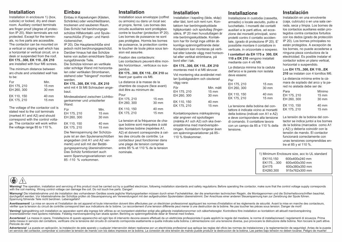
InstallationInstallation in enclosure 1) (box, cubicle) or locked, dry and cleanroom. Auxiliary contact terminalsare finger proof (degree of protec-tion IP 20). Main terminals are notprotected. Except for the termin-als, no live parts are accessible.The contactor can be mounted ona vertical or sloping wall which hasa horizontal or vertical circuit, on adesk or suspended from the roof.EH 175...300, EK 110...EK 210are installed with four M6 screws.The minimum distance betweenarc-chute and unisolated wall hasto be:For Min.EH 175, 210 15 mmEH 260, 300 30 mm
EK 110, 150 40 mmEK 175, 210 15 mm
The voltage of the contactor coil isstated next to the coil terminals(marked A1 and A2) and shouldcorrespond with the control volta-ge. The contactor will work withinthe voltage range 85 to 110 %.
InstallationInstallation i kapsling (låda, skåp)eller låst, torrt och rent rum. Kon-taktorn har beröringsskyddadehjälpkontakt- och spoluttag (finger-säkra, IP 20 men huvuduttagen ärinte beröringsskyddade. Kontak-torn har för övrigt inga utifrån åt-komliga spänningsförande delar.Kontaktorn kan monteras på verti-kal eller lutande vägg med horison-tal eller vertikal strömbana, påbord eller i tak.EH 175...300, EK 110...EK 210monteras med 4 st M6 skruvar.Vid montering ska avståndet mel-lan ljusbågsskärm och oisoleradvägg vara:För Min. måttEH 175, 210 15 mmEH 260, 300 30 mm
EK 110, 150 40 mmEK 175, 210 15 mm
Kontaktorspolens märkspänningstår angiven vid spoluttagen(märkta A1 och A2) och ska över-ensstämma med manöverspän-ningen. Kontaktorn fungerar ävenom spänningsvariationer på 85–110 % förekommer.
EinbauEinbau in Kapselungen (Kästen,Schränke) oder verschließbaren,trockenen und sauberen Raum.Das Schütz hat berührungsge-schütze Hilfskontakt- und Spule-nanschlüße (Finger- und Hand-rückensicher,IP 20). Die Hauptanschlüße sindjedoch nicht berührungsgeschützt.Darüber hinaus hat das Schützekeine von außen erreichbare Span-nungsführende Teile.Die Schütze können an vertikaleoder schräge Wand mit horizonta-len oder vertikalen Strombanen,stehend oder "hängend" montiertwerden.EH 175...300, EK 110...EK 210wird mit 4 St M6 Schrauben ange-baut.Mindesabstand zwischen Lichtbo-genkammer und unisolierterWand:Für Min.EH 175, 210 15 mmEH 260, 300 30 mm
EK 110, 150 40 mmEK 175, 210 15 mmDie Nennspannung der Schützs-pule ist an den Spulenanschlüßenangegeben (mit A1 und A2 ver-merkt) und soll mit der Betäti-gungsspannung übereinstimmen.Das Schütz funktioniert auchwenn Spannungsvariationen von85 -110 % vorkommen.
InstallationInstallation sous enveloppe (coffretou armoire) ou dans un local secet propre, fermé. Les bornes descircuits auxiliaires sont protégéescontre le toucher (protection IP 20).Les bornes de puissance ne sontpas protégées. Hormis les bornesde puissance, la protection contrele toucher de toute pièce sous ten-sion est assurée.Fixation des contacteurs:Les contacteurs peuvent-être mon-tés horizontaux , verticaux ou sus-pendus.EH 175...300, EK 110...EK 210 sefixent par quatre vis M6.La distance à la masse de lachambre de coupure (face avant)doit être au minimum de:PourEH 175, 210 15 mmEH 260, 300 30 mm
EK 110, 150 40 mmEK 175, 210 15 mm
La tension et la fréquence de cha-que bobine sont marquées à cotédes bornes bobine (repérées A1,A2) et doivent correspondre à cel-les des circuits de contrôle. Lecontacteur peut fonctionner dansune plage de tension compriseentre 85 % et 110 % de la tensionnominale.
InstallazioneInstallazione in custodia (cassetta,armadio) o locale asciutto, pulito elucchettato. I morsetti dei contattiausiliari e le parti attive, ad ecce-zione dei morsetti principali, sonoprotetti contro il contatto acciden-tale, (grado di protezione IP 20). E'possibilie montare il contattore inverticale, in orizzontale o sospeso.I contattori da EH 175 a 300, EK110 a EK 210 vengono installatimediante con 4 viti M6.La distanza minima tra la cadutadell'arco e la parete non isolatadeve essere:PerEH 175, 210 15 mmEH 260, 300 30 mm
EK 110, 150 40 mmEK 175, 210 15 mm
La tensione della bobina del con-tattore è indicata vicino ai morsettidella bobina (indicati con A1 e A2)e deve corrispondere alla tensionedi comando. Il contattore lavoracon un campo da 85 a 110 % dellatensione.
InstalaciónInstalación en una envolvente(caja, cubículo) o en una sala cer-rada, seca y limpia. Los bornes delos contactos auxiliares están pro-tegidos contra contactos fortuitoscon los dedos (grado de protecciónIP 20). Los bornes principales noestán protegidos. A excepción delos bornes, no puede accederse aninguna pieza conductora de laelectricidad. Es posible instalar elcontactor sobre un plano vertical,horizontal o suspendido.Los EH 175...300, EK 110...EK210 se instalan con 4 tornillos M6.La distancia mínima entre la cá-mara de soplado del arco y la pa-red no aislada debe ser de:Para MínimoEH 175, 210 15 mmEH 260, 300 30 mm
EK 110, 150 40 mmEK 175, 210 15 mm
La tensión de la bobina del con-tactor se indica juntoi a los bornesde la bobina (marcados como A1y A2) y debería coincidir con latensión de mando. El contactorfuncionará correctamente conunas tensiones comprendidas en-tre el 85 y el 110 %.
1) Minimum Enclosure size, acc to UL standard EK110,150 600x400x240 mm EK175....300 600x400x350 mm EH175 600x380x350 mm EH260,300 915x762x300 mm
Warning! The operation, installation and servicing of this product must be carried out by a qualified electrician, following installation standards and safety regulations. Before operating the contactor, make sure that the control voltage supply corresponds with the coil marking. Wrong control voltage can damage the coil. Do not touch live parts. Danger!
Warnung! Die inbetriebnahme und die installation des vorhandenen Gerätes sowie jegliche Wartungsarbeiten müssen durch einen Fachelektriker, der die anerkannten technischen Regeln, die Montagenormen und die Sicherheitsvorschriften beachtet, durchgefürt werden. Vor Inbetriebnahme der Schüttze prüfen ob Steuerspannung am Verwendungsort mit den aufgedruckten Spulendaten übereinstimmt. Der
Anschluss einer anderen Steuerspannung kan zur Zerstörung der Spule führen.
Spannung führende Teile nicht berühren. Lebensgefahr!
Avertissement! La mise en ceuvre et I'installation de cet appareil et toute intervention doivent être affectuées par un électricien professionnel appliquant les normes d'installation et les réglements de sécurité. Avant la mise en marche des contacteurs, vérifier que la tension du circuit de contrôle correspond bien aux indications de la bobine. Le raccordement d'une tension différente peut mener à une destruction de la bobine. Ne pas toucher les pièces sous tension. Danger de mort!
Varning! Igångsättning och installation av apparaten samt alla ingrepp bör utföras av en kompetent elektriker enligt alla gällande installationsnormer och säkerhetsregler. Kontrollera före installation av kontaktorn att aktuell manöverspänning överensstämmer med spolens märkdata. Felaktig manöverspänning kan skada spolen. Beröring av spänningsförande delar är förenat med livsfara.
Avvertenza! La messa in opera, I'installazione di questo apparecchio ed ogni tipo di intervento devona essere effettuati da un elettricista professionista il quale applichi le regole del mestiere, le norme di installazioneed i regolamenti di sicuezza. Prima della messa in servizio del contattore, verificare che la tensione del circuito di comando corrisponda esattamente a quella indicata sulla bobina. L'alimentazione con una tensione diversa, puo provocare la distruzione della bobina. Non toccare le parti attive.
Advertencia! La puesta en aplicación, la instalación de este aparato y cualquier intervención deben realizarse por un electricista profesional que aplique las reglas del oficio las normas de instalaciones y la reglamentación de seguridad. Antas de la puestaen servicio del contactor, comprobar si coinciden la tensión de mando con los datos impresos en la bobina. La conexión de otra tensión de mando puede producir la destruccion de la bobina. Las partes bajo tensión no deben tocarse. Peligro de muerte!
Pericole de vita!
Protezione contro ilcorto circuitoIl contattore può essere protettocontro il corto circuito collegandodei fusibili in serie al circuito prin-cipale. La massima portata deifusibili (tempo/corrente per tipi gI,gL o gG) à la seguente:Taglia del Fusibile max.contattore (senza relé)
Tipo 2 SecondoIEC 947-4-1
EK 110, 150 250 AEH 175, 210 355 AEK 175, 210 355 AEH 260, 300 500 A
Protección contracortocircuitosEl contactor deberá protegersecontra cortocircuitos mediante fu-sibles conectados en serie en elcircuito principal. Los fusiblesmáximos permitidos (zona tiempo/corriente, gI, gL o gG) deben serlos siguientes:Tamaño Fusible máximocontactor (sin relé)
Tipo 2 segúnIEC 947-4-1.
EK 110, 150 250 AEH 175, 210 355 AEK 175, 210 355 AEH 260, 300 500 A
KortslutningsskyddKontaktorn ska skyddas mot kort-slutning i huvudströmbanan. An-vänds vanliga knivsäkringar (ut-lösningskarakteristik gI, gL ellergG) tillåts max säkring enligt föl-jandeKontaktor- Max säkringstorlek (utan relä)
Typ 2 enligtIEC 947-4-1.
EK 110, 150 250 AEH 175, 210 355 AEK 175, 210 355 AEH 260, 300 500 A
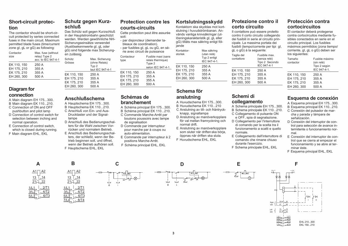
Short-circuit protec-tionThe contactor should be short-cir-cuit protected by series connectedfuses in the main circuit. Maximumpermitted blade fuses (time/currentzone gI, gL or gG) as following:Contactor Max. fuse (withoutsize relay) Type 2
acc. to IEC 947-4-1
EK 110, 150 250 AEH 175, 210 355 AEK 175, 210 355 AEH 260, 300 500 A
Protection contre lescourts-circuitsCette protection peut être assuréesoit:- par disjoncteur (demander ta-
bleaux de coordination).- par fusibles gI, gL ou gG, en sé-
rie avec circuit de puissanceContacteur Fusible maxi (sanstype relais thermique)
Type 2selon IEC 947-4-1.
EK 110, 150 250 AEH 175, 210 355 AEK 175, 210 355 AEH 260, 300 500 A
Schutz gegen Kurz-schlußDas Schütz soll gegen Kurzschlußin der Hauptstrombahn geschütztwerden. Werden gewöhnliche NH-Sicherungseinsätze verwendet(Auslösekennwerte gI, gL odergG) sind folgende max Sicherung-en zulässig.Schütz Max. SicherungGrösse (ohne Relais)
Typ 2laut IEC 947-4-1
EK 110, 150 250 AEH 175, 210 355 AEK 175, 210 355 AEH 260, 300 500 A
Esquema de conexiónA Esquema principal EH 175...300.
F Esquema principal EHL, EKL
B Esquema principal EK 110...210.C Conexión del pulsador de mar-
cha y parada y lámpara deseñalización.
D Conexión del interruptor de con-trol para selección de avance in-termitente o funcionamiento nor-mal.
E Conexión del interruptor de con-trol que se cierra al empezar elfuncionamiento y se abre al ter-minar éste.
Schemi dicollegamentoA Schema principale EH 175...300.
F Schema principale EHL, EKL
B Schema principale EK 110...210.C Collegamento di pulsante ON
e OFF, spia di segnalazione.D Collegamento per l'interruttore
di comando per la scelta tra ilfunzionamento a scatti e quellonormale.
E Collegamento dell'interruttore dicomando che rimane chiusodurante l'esercizio.
Diagram forconnectionA Main diagram EH 175...300.B Main diagram EK 110...210.C Connection of ON and OFF
pushbutton and pilot lampD Connection of control switch for
selection between inching andnormal operation.
E Connection of control switch,
F Main diagram EHL, EKLwhich is closed during running.
Schémas debranchementA Schéma principal EH 175...300.
F Schéma principal EHL, EKL
B Schéma principal EK 110...210.C Commande Marche-Arrêt par
boutons poussoirs avec lampede signalisation
D Commande par interrupteurpour marche par à coups ouauto-alimentation.
E Commande par interrupteur à 2positions Marche-Arrêt.
AnschlußschemaA Hauptschema EH 175...300.
F Hauptschema EHL, EKL
B Hauptschema EK 110...210.C Anschluß von Ein- und Aus-
Drucktaster und der Signal-lampe
D Anschluß des Bedienungsschal-ters für die Wahl zwischen Vor-rücken und normalem Betrieb.
E Anschluß des Bedienungsschal-ters, der schließt, wenn der Be-trieb beginnen soll, und öffnet,wenn der Betrieb aufhören soll.
Schema föranslutningA Huvudschema EH 175...300.
F Huvudschema EHL, EKL
B Huvudschema EK 110...210C Anslutning av till- och fråntryck-
knapp, signallampaD Anslutning av manöverkopplare
för val mellan framryckning ochnormal drift.
E Anslutning av manöverkopplaresom sluter när driften ska börja,öppnas när driften ska sluta.
A B C D E F
3
A1 A2
13 1421 22
1/L13/L25/L3 6/T3
4/T22/T1
A1 A2
13 1421 22
1/L13/L25/L3 6/T3
4/T22/T1
7/L4 8/T4
EHL 210...300EKL 150...210
35 3648
1422
47
A2
A3
A1
1321
1 L1 2 T14 T26 T3
3 L25 L3
8 T47 L4
+
I
I
0
0
Rightside
Leftside

Antes de desmontarel contactorDesactívelo:
desconectando el contactor.abriendo el circuito principaldesconectando para ello el in-terruptor principal, si existe, odesmontando los fusibles prin-cipales de las tres fases.para proteger contra cualquierintento de conexión, abra tam-bién el circuito de mando.
Prima di amontare ilcontattoreDisattivarlo mediante
disalimentazione del contattoreapertura del circuito principalespegnendo l'interruttore princi-pale, se esiste o rimuovendo ifusibili dalle 3 fasi.Per una protezione più comple-ta aprire anche il circuito di co-mando.
Maßnahmen vor demZerlegen desSchützes
Schütz ausschalten.Hauptstrom über Trennschalteroder Leistungsschalter aus-schalten oder die Hauptsicher-ungen in allen drei Phasenherausnehmen.Um Einschaltversuche zu ver-hindern auch die Betätigungs-strombahnen öffnen.
Avant toutdémontage ducontacteur
Mettre hors tension le contac-teur.Ouvrir le circuit de puissanceen cadenassant en positionouverte le dispositif de section-nement en amont du contac-teur ou à défaut en enlevantles fusibles de puissance surtoutes les phases.Mettre hors tension le circuit decontrôle pour protéger contretoute fermeture intempestive.
4
Drilling planBohrplan
Plan de perçageBorrplan
Dima di foraturaPlantilla de taladros
1) Smallest distance.Allows space for two auxiliarycontact blocks between thecontactors.
2) Gives min. distance F1 = dis-tance between the poles, onone contactor.
3) Allows space for three auxiliarycontact blocks between thecontactors.
4) Allows space for four auxiliarycontact blocks between thecontactors.
1) Mindestabstand.2 Blöcke zwischen den Schüt-zen.
2) Ergibt Maß F1 ≈ Maß zwischenden Phasen bei einem Schütz.
3) 3 Blöcke zwischen den Schüt-zen.
4) 4 Blöcke zwischen den Schüt-zen.
1) Distance minimum possible.2) Entraine F1 =entr'axe entre
pôles principaux sur un con-tacteur
3) Avec 3 blocs de contacts auxi-liaires montés entre les 2 con-tacteurs.
4) Avec 4 blocs de contacts auxi-liaires montés entre les 2 con-tacteurs.
1) Minsta möjliga mått.Ger plats för 2 hjälpkontakt-block mellan kontaktorerna.
2) Ger min. mått F1 =kontak-torns fasavstånd
3) Ger plats för 3 hjälpkontakt-block mellan kontaktorerna.
4) Ger plats för 4 hjälpkontakt-block mellan kontaktorerna.
1) Distanza minima.Con 2 blocchi di contatti montatifra i contattori .
2) Indica la distanza F1=cioè ladistanza fra le fasi di un con-tattore.
3) Con 3 blocchi di contatti montatifra i contattori .
4) Con 4 blocchi di contatti montatifra i contattori .
1) Mínima distancia permitida.Caben 2 bloques de contactoentre los contactores.
2) Indica la distancia F1 = distan-cia entre los polos de un con-tactor.
3) Caben 3 bloques de contactoentre los contactores.
4) 4 bloques de contacto entre loscontactores.
Före ingrepp ikontaktorn
Gör spänningslöst genom attslå ifrån kontaktorn.Bryt huvudströmmen genomatt slå ifrån frånskiljare eller ef-fektbrytare eller genom att ta urhuvudsäkringen i alla tre faser-na.För att förhindra tillslagsförsök,bryt även manöverströmbanan.
Before any dis-mantling of thecontactorMake dead by,
turning off the contactor.opening the main circuit byturning off the main switch, ifany, or by removing the mainfuses in all three phases.To protect against making at-tempt, open also the controlcircuit.
Dimensions in mm/Maße in mm/Dimensions en mm/Mått i mm/Dimensioni in mm/Dimensiones en mm
D2C1CC1) 2) 3) 4) For/Für/Pour/För/Per/Para
EH 175, 210 120 140 137 137 149 161 M6EH 260, 300 160 140 177 186 187 197 M6EK 110 120 140 166 166 177 187 M6EK 150 120 140 168 168 177 187 M6EK 175, 210 160 140 202 202 214 226 M6

Byte av kontakterByte kan göras med kontaktorn in-stallerad. Om någon huvudkontaktbehöver bytas, byt alla.
EK 110 och 150Tag bort ljusbågsskärmenTag bort de rörliga kontakterna.Lyft samtidigt kontakten någotuppåt så att kontaktbeläggetgår fritt. Se nedanstående figur.Byt därefter de fasta kontakter-na.Sätt i de nya rörliga kontakterna.
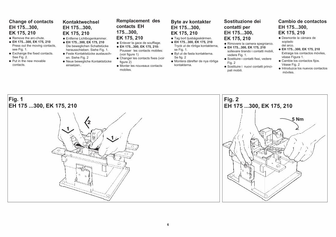
Change of contactsThe change can be done on an in-stalled contactor. Replace all of themain contacts at the same time.
EK 110 and 150Remove the arc-chute.Press out the moving contacts.Lift the contact somewhat tolet the contact easier slide out.Exchange the fixed contacts.Put in the new moving contacts.
Remplacement descontactsPeut se faire sur un contacteur in-stallé. Remplacer tous lescontacts principaux en mêmetemps.
EK 110 et 150Enlever la cage de soufflage.Pousser les contacts mobi-les: Soulever légérement le con-tact pour qu'il glisse plus facile-ment.Changer les contacts fixes.Mettre les nouveaux contactsmobiles.
Sostituzione deicontattiLa sostituzione può essere effet-tuata su un contattore installato.Sostituire i contatti principali tuttiinsieme.
EK 110 e 150Togliere la camera spegniarco.Spingere fuori i contatti mobili fa-cendo pressione su un lato.Vedere figura.Sostituire i contatti fissi.Inserire i nuovi contatti mobili.
Cambio de contactosLa sustitución puede realizarse enun contactor instalado. Cambietodos los contactos principales almismo tiempo.
EK 110 y 150Desmonte la cámara de sopladodel arco.Extraiga los contactos móviles.Levante ligeramente el contactopara permitir que éste salgamásfácilmente deslinzándose.Cambie los contactos fijos.Introduzca los nuevos contactosmóviles.
EH 175 ... 300, EK 175, 210voir page 6
EH 175 ... 300, EK 175, 210vedere pag. 6
EH 175 ... 300, EK 175, 210véase página. 6
EH 175 ... 300, EK 175, 210siehe Seite 6.
EH 175 ... 300, EK 175, 210see page 6
EH 175 ... 300, EK 175, 210se sida 6
EK 110, 150
5
KontaktwechselDer Austausch kann aufmontiertes Schütz erfolgen. Sollteein Haupt-kontaktstückausgetauscht werden, tauschealle.
EK 110 und 150Entferne Lichtbogenkammer.Entferne die beweglichen Kon-taktstücke. Die Kontaktstückegleichzeitig etwas aufwärts hebenso daß dieselben leichter heraus-geschoben verden können.Tausche danach die festenKontaktstücke.Neue bewegliche Kontaktstückeeinsetzen.
5 Nm
Cambio de contactosEH 175...300,EK 175, 210
Desmonte la cámara desopladodel arco.EH 175...300, EK 175, 210Extraiga los contactos móviles,véase Figura 1.Cambie los contactos fijos.Véase Fig. 2Introduzca los nuevos contactos móviles.
Change of contactsEH 175...300,EK 175, 210
Remove the arc-chute.EH 175...300, EK 175, 210Press out the moving contacts,see Fig. 1.Exchange the fixed contacts.See Fig. 2.Put in the new movablecontacts.
KontaktwechselEH 175...300,EK 175, 210
Entferne Lichtbogenkammer.EH 175...300, EK 175, 210Die beweglichen Schaltstückeherausschieben. Siehe Fig. 1.Feste Kontaktstücke austausch-en. Siehe Fig. 2Neue bewegliche Kontaktstückeeinsetzen..
Remplacement descontacts EH175...300,EK 175, 210
Enlever la gace de soufflage.EH 175...300, EK 175, 210:Pousser les contacts mobiles:(voir figure 1)Changer les contacts fixes (voirfigure 2)Monter les nouveaux contactsmobiles.
Sostituzione deicontatti perEH 175...300,EK 175, 210
Rimovere la camera spegniarco.EH 175...300, EK 175, 210sollevare tirando i contatti mobili,vedere Fig. 1.Sostituire i contatti fissi, vedereFig. 2Sostituire i nuovi contatti princi-pali mobili.
Byte av kontakterEH 175...300,EK 175, 210
Tag bort ljusbågsskärmen.EH 175...300, EK 175, 210Tryck ut de rörliga kontakterna,se Fig. 1.Byt ut de fasta kontakterna.Se fig. 2Montera därefter de nya rörligakontakterna.
6
Fig. 1EH 175 ...300, EK 175, 210
Fig. 2EH 175 ...300, EK 175, 210
5 Nm
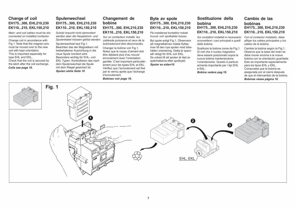
Change of coilEH175...300, EHL210,230EK110...210, EKL150,210
SpulenwechselEH175...300, EHL210,230EK110...210, EKL150,210
EH175...300, EHL210,230EK110...210, EKL150,210EH175...300, EHL210,230
EK110...210, EKL150,210Main- and coil cables must be dis-connected on installed contactor.
Schütz braucht nicht abmontiertwerden aber die Hauptstrom- undSpulenkabel müssen gelöst werden.
På installerad kontaktor måstehuvud- och spolkablar lossas.Sur un contacteur installé, les
cablesde puissance et ceux de labobinedoivent être déconnectés.
Change coil in accordance withFig.1. Note that the magnet coremust be moved over to the newcoil with kept orientation.This is important especially fortype EHL and EKL.Check that the coil is secured bythe latch after the coil exchange.
Spulenwechsel laut Fig.1. Beachten das der Magnetkern mitbeibehaltener Ausrichtung in dieneue Spule montiert wird.Besonders wichtig für EHL- undEKL Typen. Kontrollieren das nachdem Spulenwechsel die Spulemit dem Riegel gesichert ist.
Changer la bobine voir Fig.1.Notez que le noyau d’aimant doitêtre déplacé plus d’au nouvelenroulement avec I’orientationgardée. C’est important particuliér-ement pour les types EHL et EKL.Vérifiez que I’enroulement est fixépar le verrou aprés que I’échanged’enroulement.
Byt spole enligt Fig.1. Observeraatt magnetkärnan måste flyttasöver till den nya spolen med bibe-hållen orientering. Detta är speci-ellt viktigt för EHL och EKL.Se också till att spolen är låst avspärrhakarna efter spolbytet.
EH175...300, EHL210,230EK110...210, EKL150,210Sui contattori installati è necessariosconnettere i cavi principali e quellidella bobina.Sostituire la bobina coma da Fig.1.Si noti che il nucleo magneticodeve essere posizionato sopra lanuova bobina mantenendoneI’orientamento. Questo è particol-armente importante per i tipi EHLe EKL.
EH175...300, EHL210,230EK110...210, EKL150,210Con el contactor instalado, debeaflojar los cables principales y loscables de la bobina.Cambie la bobina según la Fig.1.Observe que la base del imán sedebe mover encima a la nuevabobina con la orientación guardada.Esto es importante especialmentepara los tipos EHL y EKL.Compruebe que la bobina es asegurada por el cierre despuésde que el intercambio de la bobina.
Byte av spoleChangement debobine
Sostituzione dellabobina
Cambio de lasbobinas
Fig. 1
7
N
2 3
1
EHL, EKL
Coils see page 10.Spolar se sidan10.
Spulen siehe Seite 10
Bobines voir page 10.
Bobine vedere pag.10.
Bobinas véase página 10.

Diagram Cat.No.Anschlüßschema Bestellnr.Schémas Réf.Schema BeställningsnrSchema Codice numeroEsquema Ref. pedido
SK 829 002-B
SK 829 002-C
SK 829 002-D
SK 829 002-E 1)
SK 829 002-A 2)
ACCESSORIESAdditional auxiliarycontact blocksAC-versionA maximum of totally 4 blocks canbe mounted on the contactor.Technically, all blocks are identi-cal, which means that the sameblock can be used in all three posi-tions. If the demand for correct po-sition marking has to be met, orderblock B, C etc. mounted as shownin the figure 1.
DC-versionA maximum of totally 2 contactblock can be mounted on the con-tactor. The right side is blocked bythe operating unit for DC.1) SK 829 002-E is a special auxi-
liary contact block with overlap-ping. Can be mounted on thecontactor's right side only . Noother block can be mounted out-side (figure 2). Contact 35–36has late opening. 47–48 has lateclosing.
2) Block A, spare for the contac-tor's auxiliary contact block.
TILLBEHÖRExtra hjälpkontakt-blockVäxelströmsutförandeHögst 4 kontaktblock totalt kanmonteras på kontaktorn. Teknisktär blocken likadana, så sammablock kan användas på alla treplatserna. Men om krav på skildauttagsbeteckningar finns beställsblock B, C och D som placerasenligt figur 1.
LikströmsutförandeHögst 2 kontaktblock totalt kanmonteras på kontaktorns vänstrasida. Höger sida är blockerad avmanöverenheten för likström.1) SK 829 002-E är ett speciellt
hjälpkontaktblock med överlapp-ning. Kan endast placeras påkontaktorns högra sida. Inget yt-terligare block kan monteras ut-anpå. Kontakt 35–36 har senbrytning och 47–48 har sen slut-ning.
2) Block A är ersättning för befint-ligt block.
8
ACCESSOIRESContacts auxiliairessupplémentairesPour contacteurs avec circuitde commande en courant alter-natif – AC4 blocs de contacts auxiliairessupplémentaires peuvent êtremontés sur l'appareil standard liv-ré avec le bloc A monté. Les blocssont montables indifféremmentdans les 3 positions, cependant sion veut conserver un repéragecorrect, il faut respecter l'ordre demontage indiqué B–C...(Fig. 1).
Pour contacteurs avec circuitde commande en courant conti-nu– DCMaximum 2 bloc de contacts auxi-liaires peut être ajouté à gauchedu contacteur. Le côté droit est oc-cupé par le "bloc: résistanced'economie et contact d'insertion".1) SK 829 002-E est un bloc de
contacts auxiliaires spécial à recouv- rement. Il doit être montéà droite du contacteur et ne per-met pas de rajouter un bloc decontacts auxiliaires supplémen-taire (Fig. 2). Le contact 35–36est à ouverture retardée. Le con-tact 47–48 est à fermetureavancèe.
2) SK 829 002- A est livré montésur le contacteur standard etpeut être commandé en re-change.
ZUBEHÖRZusätzlicheHilfsschalterblöckeDrehstromausführungHöchstens 4 Kontaktblöcke kön-nen total am Schütz montiert wer-den. Technisch sind die Blöckegleichwertig, der gleiche Blockkann also auf allen drei Plätzenangewendet werden. Falls jedochverschiedene Anschlußbe-zeichnungen gefordert werden,bestellt man Block B, C und D diegemäß Fig. 1 angebracht werden.
GleichstromausführungHöchstenst 2 Kontaktblöcke kön-nen total auf der linken Seite desSchützes angebracht werden. Dierechte Seite ist vom Sparwieder-stand besetzt.1)SK 829 002-E ist ein spezieller
Hilfskontaktblock mit Überlapp-ung. Kann nur auf der rechtenSeite des Schützes angebrachtwerden. Kein weiterer zusätzli-cher Block kann montiert werden.Die Kontakte 35–36 haben Öff-nungsverzug, und 47–48 habenSchließverzug
2)Block A ist Ersatz für den be-findlichen Block.
ACCESSORIBlocchetti aggiuntividi contatti ausiliariVersione in c.a.Possono essere montati fino a unmassimo di 4 blocchetti di contattioltre a quello già montato di fabbri-ca. Tecnicamente tutti i blocchettisono identici, il che significa che lostesso blocchetto può essere mon-tato in tutte e 3 le posizioni. Se vie-ne richiesta la corretta numerazio-ne del morsetti, è necessario ordi-nare il blocchetto B, C ecc. e mon-tarlo come indicato nella figura 1.
Versione in c.c.Può essere montato 2 blocchettodi contatti ausiliari sul lato sinistrodel contattore. Il lato de-stro è oc-cupato dalla resistenza in c.c.1)SK 829 002-E è un blocchetto
speciale di contatti ausiliari adoppia punta. Può essere mon-tato solo sul lato destro del con-tattore e non è possibile aggiun-gere altri contatti su quel lato.(Figura 2). Il contatto 35–36 è ri-tardato all'apertura, il 47–48 è ri-tardato in chiusura.
2)Blocchetto A, ricambio delblocchetto di contatti ausiliarimontato di serie sul contattore.
ACCESORIOSBloques adicionalesde contactos auxilia-resVersión c.a.Puede instalarse un máximo de 4bloques en el contactor, apartedel ya instalado de forma estandár.Técnicamente, todos los bloquesson idénticos, lo que supone quepuede emplearse el mismo bloqueen las tres posiciones. Si debecumplirse la exigencia de unaidentificación correcta de las nu-mera, solicite los bloques B, C etc.instalados como se muestra en laFig. 1.Versión c.c.Puede instalarse un máximo dedos bloque de contactos en laparte izguierda del contactor. Laparte derecha está bloqueada porla unidad de accionamiento parac.c.1) SK 829 002-E es un bloque
especial de contactos auxiliarescon solapamiento. Puede instalarse sólo en la parte derechadel contactor. Ningún otro bloque puede instalarse fuera (Figura 2). Los contactos 35–36tienen apertura retardada. Los47–48 tienen cierre retardado.
2) Bloque A, recambio del bloquede contactos auxiliares del con-tactor.
2 .giF1 .giF

9
KabelklämmorAntal 1 st
För mm2 Beställningsnr
För Cu-kabelEK 110 25–70 SK 175 0001
EK 110 25–120 SK 175 0003
EH 175...210,EK 150...210 35–150 SK 175 0005
EH 175...210,EK 150...210 25–185 SK 175 0007
EH 260, 300 70–300 SK 175 0009
För Al-kabel (och Cu-kabel)EK 110 10–70 SK 173 001-AB
EH 175...210EK 150...210 35–120 SK 173 001-AC
EH 260, 300 70–300 SK 173 001-AD
Obs: För att UL-godkännandeskall gälla måste speciellaklämmor användas, kontaktanärmaste säljkontor.
MorsettiQuantità: 1
Per mm2 Codice numero
Per cavo CuEK 110 25–70 SK 175 0001
EK 110 25–120 SK 175 0003
EH 175...210,EK 150...210 35–150 SK 175 0005
EH 175...210,EK 150...210 25–185 SK 175 0007
EH 260, 300 70–300 SK 175 0009
Per cavo Al (e cavo Cu)EK 110 10–70 SK 173 001-AB
EH 175...210EK 150...210 35–120 SK 173 001-AC
EH 260, 300 70–300 SK 173 001-AD
N.B.: Affinche l'omologazione ULsia valida, devono essereutilizzati morsetti speciali.
ConnecteursVente parl 1.
Pour mm2 Réf.
Pour câble CuEK 110 25–70 SK 175 0001
EK 110 25–120 SK 175 0003
EH 175...210,EK 150...210 35–150 SK 175 0005
EH 175...210,EK 150...210 25–185 SK 175 0007
EH 260, 300 70–300 SK 175 0009
Pour câble Al (ou Cu)EK 110 10–70 SK 173 001-AB
EH 175...210EK 150...210 35–120 SK 173 001-AC
EH 260, 300 70–300 SK 173 001-AD
Note: Pour conformité avec UL,utiliser des connecteursspéciaux, nous consulter.
KabelklemmenAnzahl 1 Stück
Für mm2 Bestellnr.
Für Cu-KabelEK 110 25–70 SK 175 0001
EK 110 25–120 SK 175 0003
EH 175...210,EK 150...210 35–150 SK 175 0005
EH 175...210,EK 150...210 25–185 SK 175 0007
EH 260, 300 70–300 SK 175 0009
Für Al-Kabel (und Cu-Kabel)EK 110 10–70 SK 173 001-AB
EH 175...210EK 150...210 35–120 SK 173 001-AC
EH 260, 300 70–300 SK 173 001-AD
Achtung: Soll UL-Approbationgelten sind spezielleAnschlußklemmen erfor-derlich. Bitte bei einenABB-Vertriebsbüro nach-fragen.
Cable clampsQuantity 1.
For mm2 Cat.No.
For Cu-cableEK 110 25–70 SK 175 0001
EK 110 25–120 SK 175 0003
EH 175...210,EK 150...210 35–150 SK 175 0005
EH 175...210,EK 150...210 25–185 SK 175 0007
EH 260, 300 70–300 SK 175 0009
For Al-cable (and Cu-cable)EK 110 10–70 SK 173 001-AB
EH 175...210EK 150...210 35–120 SK 173 001-AC
EH 260, 300 70–300 SK 173 001-AD
Note: For UL-approval, to be valid,special clamps must beused. Contact your localsales office.
Terminales paracables Cantidad 1
Para mm2 Ref. pedido
Para cable CuEK 110 25–70 SK 175 0001
EK 110 25–120 SK 175 0003
EH 175...210,EK 150...210 35–150 SK 175 0005
EH 175...210,EK 150...210 25–185 SK 175 0007
EH 260, 300 70–300 SK 175 0009
Para cable Al (y cable Cu)EK 110 10–70 SK 173 001-AB
EH 175...210EK 150...210 35–120 SK 173 001-AC
EH 260, 300 70–300 SK 173 001-AD
NOTA: Para UL-homologación,utilizar terminalesespeciales, consultar.

Bobinasc.a. y c.c.Para Ref.pedido
sustituir por loscódigos de letrassegún la tabla,véase página. 11.
EH 175, 210 yEK 110, 150 SK 825 400-
EH 260, 300 yEK 175, 210 SK 826 400-
Unidades de accionamíentoVéase figura inferiorBobina y bloque de contactos
Para Ref. pedido sustituir por loscódigos de letrassegún la tabla véasepágina. 11.
EH 175, 210 yEK 110, 150 SK 825 450-
EH 260, 300 yEK 175, 210 SK 826 450-
BobinesCourant alternatif et continuPour Réf.
compléterpar code lettres,Voir tableau,page 11.
EH 175, 210 etEK 110, 150 SK 825 400-
EH 260, 300 etEK 175, 210 SK 826 400-
Ensemble pour courantcontini (Voir figure ci-dessous)Bobine livrée avec un bloc com-prenant contact d'insertion
Pour Réf. compléterpar code lettres,Voir tableau, page 11
EH 175, 210 et
d.c operated Bi-frequency coil Magnetic latch
EK 110, 150 SK 825 450-
EH 260, 300 etEK 175, 210 SK 826 450-
CoilsAC and DCFor Cat.No.
replace withcode lettersacc. to the tableon page 11.
EH 175, 210 andEK 110, 150 SK 825 400-
EH 260, 300 andEK 175, 210 SK 826 400-
Operating units for DCSee the figure belowCoil and contact block
For Cat.No. replace with
code lettersacc. to the tableon page 11.
EH 175, 210 andEK 110, 150 SK 825 450-
EH 260, 300 andEK 175, 210 SK 826 450-
Spolarväxelström och likströmFör Beställningsnr
ersätts avkodbokstäverenligt tabellpå sida 11.
EH 175, 210 ochEK 110, 150 SK 825 400-
EH 260, 300 ochEK 175, 210 SK 826 400-
Manöverenheter förlikström Se figur nedanSpole och kontaktblock
För Beställningsnr ersätts av
kodbokstäverenligt tabellpå sida 11.
EH 175, 210 ochEK 110, 150 SK 825 450-
EH 260, 300 ochEK 175, 210 SK 826 450-
SpulenDS und GSFür Bestellnummer
ersetzen mitKode-Buchstabenlaut TabelleSeite 11.
EH 175, 210 undEK 110, 150 SK 825 400-
EH 260, 300 undEK 175, 210 SK 826 400-
Betätigungseinheit fürGleichstrom Siehe Fig. untenSpule und Hilfskontaktblock
Für Bestellnummer ersetzen mit
Kode-Buchstabenlaut TabelleSeite 11.
EH 175, 210 undEK 110, 150 SK 825 450-
EH 260, 300 undEK 175, 210 SK 826 450-
10
Bobinec.a. e c.c.Per Codice numero
Sostituire aicodici alfabeticidella tabella .Vedere pag. 11.
EH 175, 210 eEK 110, 150 SK 825 400-
EH 260, 300 eEK 175, 210 SK 826 400-
Unita di funzionamentoin c.c. Vedere figura sotto indicataComprende bobina e blocchettocontattiPer Codice numero
Sostituire aicodici alfabeticidella tabellaVedere pag. 11.
EH 175, 210 eEK 110, 150 SK 825 450-
EH 260, 300 eEK 175, 210 SK 826 450-
EH 175...300
EK 110...210
EK 110...210 EHL 210...300EKL 150...210
EH 175...300
A2
A1
A2A1
Rightside
Leftside
Rightside
Leftside
35 3648 E
A
E
A
1422
47
1321
1 L1 2 T14 T26 T3
3 L25 L3
35 3648
1422
47
13218 T47 L4
1 L1 2 T14 T26 T3
3 L25 L3
8 T47 L4
35 3648
1422
47
A2
A3
A1
1321
1 L1 2 T14 T26 T3
3 L25 L3
8 T47 L4
+
I
I
0
0
Rightside
Leftside
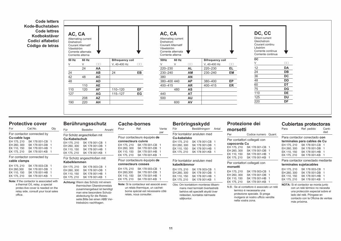
AC, CAAlternating currentDrehstromCourant AlternatifVäxelströmCorrente alternataCorriente alterna
50 Hz 60 Hz Bifrequency coil 50Hz 60 Hz Bifrequency coilV V V, 40-400 Hz V V V, 40-400 Hz
24 AA 220–230 AL 220–230 EL24 AB 24 EB 230–240 AM 230–240 EM42 48 AC 380 AN48 AD 380–400 440 AP 380–400 EP
110 AE 400–415 AR 400–415 ER110 120 AF 110–120 EF 480 AS127 AG 115–127 EG 440 AT
208 AZ 500 AU190 220 AH 600 AV
11
BerührungsschutzFür Bestellnr Anzahl
Für Schütz angeschloßen mitCu-KabelschuhEH 175, 210 SK 178 001-CB 1EH 260, 300 SK 178 001-DB 1EK 110, 150 SK 178 001-HB 1EK 175, 210 SK 178 001-KB 1
Für Schütz angeschloßen mitKabelklemmenEH 175, 210 SK 178 003-CB 1EH 260, 300 SK 178 001-DB 1EK 110, 150 SK 178 001-HB 1EK 175, 210 SK 178 001-KB 1
Achtung: Wenn das Schütz mit einemthermischen Überstromrelaiszusammengebaut ist benötigtman eine besondere Schutz-abdeckung für die Relais-seite.Bitte bei einen ABB Ver-triebsbüro nachfragen.
Protective coverFor Cat.No. Qty
For contactor connected byCu-cable lugsEH 175, 210 SK 178 001-CB 1EH 260, 300 SK 178 001-DB 1EK 110, 150 SK 178 001-HB 1EK 175, 210 SK 178 001-KB 1
For contactor connected bycable clampsEH 175, 210 SK 178 003-CB 1EH 260,300 SK 178 001-DB 1EK 110, 150 SK 178 001-HB 1EK 175, 210 SK 178 001-KB 1
Note: If the contactor is associated witha thermal O/L relay, a specialprotec-tive cover is needed on therelay side, consult your local salesoffice.
Cache-bornesPour Réf. Vente
par
Pour contacteurs équipés deconnecteurs cuivreEH 175, 210 SK 178 001-CB 1EH 260, 300 SK 178 001-DB 1EK 110, 150 SK 178 001-HB 1EK 175, 210 SK 178 001-KB 1
Pour contacteurs équipés deconnecteurs cossesEH 175, 210 SK 178 003-CB 1EH 260,300 SK 178 001-DB 1EK 110, 150 SK 178 001-HB 1EK 175, 210 SK 178 001-KB 1
Note: Si le contacteur est associé avecun relais thermique, un cachet-borne spécial est nécessaire côtérelais, nous consulter.
BeröringsskyddFör Beställningsnr Antal
För kontaktor ansluten medCu-kabelskoEH 175, 210 SK 178 001-CB 1EH 260, 300 SK 178 001-DB 1EK 110, 150 SK 178 001-HB 1EK 175, 210 SK 178 001-KB 1
För kontaktor ansluten medkabelklämmorEH 175, 210 SK 178 003-CB 1EH 260, 300 SK 178 001-DB 1EK 110, 150 SK 178 001-HB 1EK 175, 210 SK 178 001-KB 1
Obs: Om kontaktorn monteras tillsam-mans med termiskt överlastreläbehövs ett speciellt skydd överreläsidan, kontakta närmastesäljkontor.
Protezione deimorsettiPer Codice numero Quant.
Per contattori collegati concapocorda CuEH 175, 210 SK 178 001-CB 1EH 260, 300 SK 178 001-DB 1EK 110, 150 SK 178 001-HB 1EK 175, 210 SK 178 001-KB 1
Per contattori collegati conmorsettiEH 175, 210 SK 178 003-CB 1EH 260, 300 SK 178 001-DB 1EK 110, 150 SK 178 001-HB 1EK 175, 210 SK 178 001-KB 1
N.B.: Se al contattore è associato un relétermico è necessaria unaprotezione speciale. Si pregarivolgersi al nostro ufficio venditenella vostra zona.
Cubiertas protectorasPara Ref. pedido Canti-
dad
Para contactor conectado conterminales para cables de CuEH 175, 210 SK 178 001-CB 1EH 260, 300 SK 178 001-DB 1EK 110, 150 SK 178 001-HB 1EK 175, 210 SK 178 001-KB 1
Para contactor conectado medianteterminales sujetacablesEH 175, 210 SK 178 003-CB 1EH 260, 300 SK 178 001-DB 1EK 110, 150 SK 178 001-HB 1EK 175, 210 SK 178 001-KB 1
NOTA: Si el contactor se monta juntocon un relé térmico no necesitauna protección especial sobre ellado del relé. Póngase encontacto con la Oficina de ventasmás próxima.
Code lettersKode-Buchstaben
Code lettresKodbokstäver
Codici alfabeticiCódigo de letras
DC, CCDirect currentGleichstromCourant continuLikströmCorrente continuaCorriente continua
DCV
12 DA24 DB36 DC48 DD60 DT75 DG110 DE125 DU220 DF
AC, CAAlternating currentDrehstromCourant AlternatifVäxelströmCorrente alternataCorriente alterna

ABB AB, Control ProductsS-721 61 Västerås, SwedenTelephone +46 21–32 07 00
Instr. 5309 660-57 Edition C November 2015
Care
Thermal overloadrelay
The contactors do not need anycare except for an occasionalcheck up of contact condition. Thecontact wear depends mainly onburning from the arc and will in-crease considerably when the con-tactor is used for inching or directreversing (AC-4 operations; com-pare with the electrical endurancediagram in the catalogue). Contac-tors regularly used for AC-4 opera-tions need more frequent inspec-tions, but main contact exchangeis not necessary until the contacttips are almost totally worn out.
Wartung
Thermisches Über-lastrelais
Die Schütze benötigen keine War-tung außer einer gelegentlichenKontrolle, daß die Hauptkontaktenicht verschließen sind. Der Ver-schleiß beruht praktisch vollständigauf Abbrennung durch EIN- undAUS-schaltlichtbogen. Beachte,daß bei Betrieb, bei dem dasSchütz oft den Startstrom ausschal-ten muß (Vorrücken, Direktum-kehr), eine Inspektion öfter durch-geführt werden muß, vergleiche mitden Lebensdauerkennlinien im Ka-talog. Die Kontaktstücke brauchenjedoch nicht ausgewechselt zu wer-den, bevor die Schaltflächen fastganz verschließen sind.
Entretien
Relais de surchargethermique
Les contacteurs ne nècessitentaucun entretien, à l'exception del'examen pèriodique de l'ètat descontacts. L'usure des contacts dé-pend surtout de l'érosion due àl'arc électrique et augmente con-sidérablement quand le contacteurest utilisé en marche par à coupsou en inversion de sens de mar-che (catégorie d'emploi AC-4; voircourbes d'endurance électrique).Les contacteurs utilisés en catégo-rie AC-4 ont besoin d'examens pé-riodiques, mais l'échange des con-tacts n'est pas nécessaire tant queleurs pastilles ne sont pas totale-ment usées.
Skötsel
Termiskt överlastrelä
Kontaktorerna behöver ingen sköt-sel annat än viss kontroll att intehuvudkontakterna är utslitna. Slita-get beror praktiskt taget helt på av-bränning genom slut- och brytljus-bågarna. Märk, att vid drift där kon-taktorn ofta får bryta startströmmen(framryckning, direktreversering)ökar behovet av inspektion; jämförlivslängdskurvorna i katalogen.Kontakterna behöver dock inte by-tas förrän kontaktbeläggen är näs-tan helt utslitna.
Manutenzione
Relè termici disovraccarico
Il contattore non necessita alcunamanutenzione tranne nel caso diverifica delle condizioni dei contat-ti. L'usura dei contatti dipende prin-cipalmente dalle bruciature provo-cate dall'arco e aumenta notevol-mente quando il contattore vieneimpiegato a scatti o per inversione(categoria d'impiego AC4; confront-are con diagramma di durata elettri-ca sul catalogo). I contattori utiliz-zatti in AC4 necessitano di controllipiù frequenti, ma la sostituzione deicontatti non è necessaria se le es-tremità degli stessi non sono quasitotalmente consumate.
Cuidado
Relé térmico desobrecarga
Los contactores no requierenningún cuidado a exceptión de unacomprobación ocasional del esta-do de los contactos. El estado deéstos depende fundamentalmentedel quemado provocado por elarco y aumentará considerable-mente cuando el contactor seemplee para avance paso a pso opara inversión directa (funciona-miento en la categoría de empleoAC-4; consulte la tabla de longevi-dad eléctrica del catálogo). Loscontactos utilizados habitualmentepara accionamientos de categoríaAC-4 requiren una inspección másfrecuente, pero el cambio de loscontactos principales no es nece-sario hasta que las puntas de loscontactos no están casi completa-mente desgastadas.
Pour EH175, 210UL 508: For use only with the ABB T200DU Series oveload relays
För EH175, 210 Per EH175, 210 Para EH175, 210For EH175, 210 Für EH175, 210
www.abb.com/lowvoltage