manual de instalación, operación y mantenimiento scd scb en_esp 7... · autorizado o por personal...
TRANSCRIPT

1
Manual de Instalación, Operación y MantenimientoLea y guarde estas instrucciones para referencia futura. Lea detenidamente antes de ensamblar, instalar, operar o dar mantenimiento al producto que se describe. Por su propia seguridad y la de aquellos que lo rodean, preste atención a toda la información de seguridad. Si no respeta las instrucciones, puede provocar lesiones corporales o daños a la propiedad.
Ventiladores Centrífugos en Línea
Documento 479713Modelo SCD y SCB
Ventiladores Centrifugos en Línea
Información de Seguridad General
Sólo personal calificado debe instalar este ventilador. El personal debe tener una clara comprensión de estas instrucciones y debe ser consciente de las precauciones generales de seguridad. Una instalación inadecuada puede resultar en una descarga eléctrica, lesiones debido al entrar en contacto con las partes, así como otros peligros potenciales en movimiento. Otras consideraciones pueden ser necesarias si hay actividad sísmica. Si necesita más información, póngase en contacto con un ingeniero profesional con licencia antes de seguir adelante.
1. Siga todos los códigos eléctricos locales y deseguridad, así como el código eléctrico nacional(NEC) y la Agencia Nacional de protección deincendios (NFPA), en donde sea aplicable.
2. La rotación de la rueda es esencial. Debe estar libreal girar sin golpear o frotar objetos estacionarios.
3. El motor debe estar firmemente y adecuadamenteconectado a tierra.
4. No exceda las RPM de velocidad catalogada.Los ajustes de velocidad del motor tienen efectossignificativos a la carga del motor. Si se cambianlas RPM la corriente del motor debe medirse paraasegurarse de que no exceda los amperios de laplaca del motor.
5. No permita que el cable de alimentación seenrosque o entre en contacto con aceite, grasa,superficies calientes o sustancias químicas.Reemplace el cable inmediatamente si está dañado.
6. Verifique que la fuente de alimentación escompatible con el equipo.
7. Nunca abra las puertas de acceso a un ductomientras está funcionando el ventilador.
PELIGROSiempre desconecte, bloque y etiquete la fuente de alimentación eléctrica antes de instalar o dar servicio. Si no desconecta la fuente de alimentación eléctrica puede ocasionar incendios, descargas o lesiones graves.
ADVERTENCIACuando se repare el ventilador, el motor puede estar lo suficientemente caliente como para causar una lesión. Permita que el motor se enfríe antes de darle servicio.
ADVERTENCIADebe tenerse precaución en atmósferas explosivas.
Modelo SCD Transmisión DirectaEl modelo SCD es un extractor centrífugo en línea de transmisión directa. Estos ventiladores están diseñados específicamente para aplicaciones en línea. Cada ventilador deberá llevar una placa metálica permanentemente adherida que contenga el número de modelo y número de serie.
Modelo SCB
Transmisión por CorreaEl modelo SCB es un extractor centrífugo en línea de transmisión por correa. Estos ventiladores están diseñados específicamente para aplicaciones en línea. Cada ventilador deberá llevar una placa metálica permanentemente adherida que contenga el número de modelo y número de serie.
ADVERTENCIA DE NOM
Este aparato no se destina para utilizarse por personas (incluyendo niños) cuyas capacidades físicas, sensoriales o mentales, sean diferentes o estén reducidas, o carezcande experiencia o conocimiento, a menos que dichaspersonas reciban una supervisión o capacitación para elfuncionamiento del aparato por una persona responsablede su seguridad.Los niños deben supervisarse para asegurar que ellos noempleen los apratos como juguete.
IMPORTANTE
Si el cordón de alimentación es dañado, este debe sustituirse por el fabricante, por su agente de servicio autorizado o por personal calificado con el fin de evitar un peligro.

2 Ventiladores Centrífugos en Línea
RecepciónAl recibir el producto, revíselo para asegurarse de que estén todos los artículos usando el conocimiento de embarque, para garantizar que se recibieron todos los artículos. Revise todas las cajas para ver si han sufrido daños en el transporte antes de aceptar la entrega. Infórmele al transportista si encuentra daños. El transportista pondrá una notificación en el recibo de entrega, reconociendo cualquier daño al producto. Todos los daños se deben anotar en todas las copias del conocimiento de embarque, el que es refrendado por el transportista que hizo la entrega. El transportista debe llenar un Informe de inspección del transportista en la entrega y se le debe informar al Departamento de Tránsito. Si el producto sufre daños al llegar, presente una queja al transportista. Cualquier daño físico en la unidad después de haberla aceptado no es responsabilidad del fabricante.
DesembalajeCompruebe si recibió todas las partes necesarias y que estén en sus cantidades correctas. Si falta algún artículo, infórmelo a su representante local para organizar la obtención de las partes faltantes. Algunas veces no es posible enviar todos los artículos juntos a causa de la disponibilidad de transporte y el espacio en el transporte. Las confirmaciones de envío se deben limitar sólo a los artículos que se encuentran en el conocimiento de embarque.
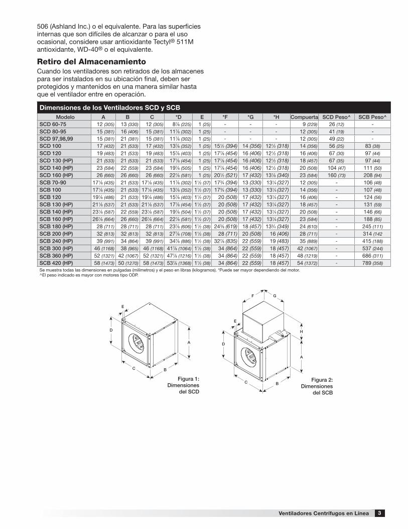
ManejoColoque el ventilador a la posición deseada y determine la posición de los paneles de acceso, la descarga y el motor. Asegúrese de que la entrada y salida tienen por lo menos 21/2 veces el diámetro de rueda (diámetro del ducto) antes de obstrucciones como un codo o de transición. Coloque el ventilador en un marcoadecuado como se especifica; se recomiendan losaisladores de vibración colgante o base. Consulte latabla en la página 3 para dimensiones físicas, utilizandolas figuras 1 y 2. Las dimensiones de instalación yvibración consulte las páginas 4 y 5. Debe revisar lacompatibilidad del amperaje y el voltaje del motor antesde la última conexión eléctrica. Una vez conectadoslos cables eléctricos al interruptor de seguridadsuministrado de fábrica asegúrese de que cumpla conlos códigos locales y nacionales.
AlmacenamientoLos ventiladores están protegidos contra daños durante el envío. Si no se puede instalar y utilizar de forma inmediata, se deben tomar precauciones para prevenir el deterioro de la unidad durante su almacenamiento. El usuario es responsable del ventilador y sus accesorios durante su almacenamiento. El fabricante no se hace responsable por los daños que ocurran durante el almacenamiento. Estas sugerencias se entregan únicamente para comodidad del usuario.
InteriorEl ambiente ideal para el almacenamiento de los ventiladores es en interiores, suspendidos, con una atmósfera de baja humedad que esté sellada
para prevenir la entrada de polvo, lluvia o nieve. Las temperaturas se deben mantener de manera uniforme entre -1º C y 43º C (30° F y 110° F), las grandes oscilaciones de temperatura pueden producir condensación y “sudor” en las partes metálicas. Todos los accesorios deben estar almacenados al interior, en una atmósfera limpia y seca.Elimine cualquier acumulación de suciedad, agua, hielo o nieve y seque las piezas antes de trasladarse al interior. Para evitar “sudor” de piezas metálicas, deje que las piezas alcancen la temperatura ambiente. Para secar las piezas y paquetes, utilice un calentador eléctrico portátil para deshacerse de cualquier acumulación de humedad. Afloje la cubierta del embalaje o revestimientos para permitir la circulación de aire y para permitir una inspección periódica. La unidad debe estar almacenada suspendida al menos 8,9 cm (3,5 pulg.) con bloques de madera envueltos con papel antihumedad o cubiertas de polietileno. Deben quedar corredores entre las partes y por los muros para permitir la circulación del aire y dar espacio para las inspecciones.
ExteriorSi fuese absolutamente necesario, los ventiladores diseñados para aplicaciones al aire libre se pueden almacenar en el exterior. Se necesitan calzas y corredores para los brazos de soporte y los equipos de arrastre.
El ventilador se debe colocar sobre una superficie nivelada para evitar que el agua se filtre al ventilador. Se debe elevar el ventilador a una altura adecuada con bloques de madera, para que quede sobre los niveles de agua y nieve. Ubique las partes lo suficientemente separadas para permitir la circulación del aire, luz y espacio para inspecciones periódicas. Para minimizar la acumulación de agua, coloque todas las partes del ventilador sobre los soportes para que el agua escurra.
No cubra las partes con plástico ni lonas, dado que éstas generan condensación de humedad del aire que pasa por los ciclos de calentamiento y de enfriamiento.
Se deben fijar las hélices del ventilador para evitar que giren debido a los vientos fuertes.
Inspección y Mantenimiento durante el AlmacenamientoInspeccione los ventiladores una vez al mes durante su almacenamiento. Mantenga un registro de las inspecciones y mantenimientos que se lleven a cabo.Si se encuentra humedad o acumulaciones de suciedad en las partes, se debe ubicar la fuente y eliminarla. En cada inspección, gire la hélice manualmente unas diez a quince revoluciones para distribuir el lubricante en el motor. Cada tres meses el motor deber ser encendido. Si la pintura se empieza a deteriorar, considera un retoque o reparación.
Las partes revestidas con antioxidante se deben restaurar a su condición adecuada si aparecen señales de oxidación. Elimine inmediatamente el revestimiento antioxidante original con solvente de petróleo y limpie con paños que no suelten pelusas. Pula todo el óxido restante de la superficie. No arruine la continuidad de las superficies. Limpie completamente con Tectyl®
3Ventiladores Centrífugos en Línea
506 (Ashland Inc.) o el equivalente. Para las superficies internas que son difíciles de alcanzar o para el uso ocasional, considere usar antioxidante Tectyl® 511M antioxidante, WD-40® o el equivalente.
Retiro del AlmacenamientoCuando los ventiladores son retirados de los almacenes para ser instalados en su ubicación final, deben ser protegidos y mantenidos en una manera similar hasta que el ventilador entre en operación.
Dimensiones de los Ventiladores SCD y SCBModelo A B C *D E *F *G *H Compuerta SCD Peso^ SCB Peso^
SCD 60-75 12 (305) 13 (330) 12 (305) 87⁄8 (225) 1 (25) - - - 9 (229) 26 (12) -SCD 80-95 15 (381) 16 (406) 15 (381) 117⁄8 (302) 1 (25) - - - 12 (305) 41 (19) -SCD 97,98,99 15 (381) 21 (381) 15 (381) 117⁄8 (302) 1 (25) - - - 12 (305) 49 (22) -
SCD 100 17 (432) 21 (533) 17 (432) 137⁄8 (352) 1 (25) 151⁄2 (394) 14 (356) 121⁄2 (318) 14 (356) 56 (25) 83 (38)
SCD 120 19 (483) 21 (533) 19 (483) 157⁄8 (403) 1 (25) 177⁄8 (454) 16 (406) 121⁄2 (318) 16 (406) 67 (30) 97 (44)
SCD 130 (HP) 21 (533) 21 (533) 21 (533) 177⁄8 (454) 1 (25) 177⁄8 (454) 16 (406) 121⁄2 (318) 18 (457) 67 (35) 97 (44)
SCD 140 (HP) 23 (584) 22 (559) 23 (584) 197⁄8 (505) 1 (25) 177⁄8 (454) 16 (406) 121⁄2 (318) 20 (508) 104 (47) 111 (50)
SCD 160 (HP) 26 (660) 26 (660) 26 (660) 227⁄8 (581) 1 (25) 201⁄2 (521) 17 (432) 137⁄8 (340) 23 (584) 160 (73) 208 (94)
SCB 70-90 171⁄8 (435) 21 (533) 171⁄8 (435) 117⁄8 (302) 11⁄2 (37) 173⁄4 (394) 13 (330) 131⁄4 (327) 12 (305) - 106 (48)
SCB 100 171⁄8 (435) 21 (533) 171⁄8 (435) 137⁄8 (352) 11⁄2 (37) 173⁄4 (394) 13 (330) 131⁄4 (327) 14 (356) - 107 (48)
SCB 120 191⁄8 (486) 21 (533) 191⁄8 (486) 157⁄8 (403) 11⁄2 (37) 20 (508) 17 (432) 131⁄4 (327) 16 (406) - 124 (56)
SCB 130 (HP) 211⁄8 (537) 21 (533) 211⁄8 (537) 177⁄8 (454) 11⁄2 (37) 20 (508) 17 (432) 131⁄4 (327) 18 (457) - 131 (59)
SCB 140 (HP) 231⁄8 (587) 22 (559) 231⁄8 (587) 197⁄8 (504) 11⁄2 (37) 20 (508) 17 (432) 131⁄4 (327) 20 (508) - 146 (66)
SCB 160 (HP) 261⁄8 (664) 26 (660) 261⁄8 (664) 227⁄8 (581) 11⁄2 (37) 20 (508) 17 (432) 131⁄4 (327) 23 (584) - 188 (85)
SCB 180 (HP) 28 (711) 28 (711) 28 (711) 237⁄8 (606) 11⁄2 (38) 243⁄8 (619) 18 (457) 133⁄4 (349) 24 (610) - 245 (111)
SCB 200 (HP) 32 (813) 32 (813) 32 (813) 277⁄8 (708) 11⁄2 (38) 28 (711) 20 (508) 16 (406) 28 (711) - 314 (142
SCB 240 (HP) 39 (991) 34 (864) 39 (991) 347⁄8 (886) 11⁄2 (38) 327⁄8 (835) 22 (559) 19 (483) 35 (889) - 415 (188)
SCB 300 (HP) 46 (1168) 38 (965) 46 (1168) 417⁄8 (1064) 11⁄2 (38) 34 (864) 22 (559) 18 (457) 42 (1067) - 537 (244)
SCB 360 (HP) 52 (1321) 42 (1067) 52 (1321) 477⁄8 (1216) 11⁄2 (38) 34 (864) 22 (559) 18 (457) 48 (1219) - 686 (311)
SCB 420 (HP) 58 (1473) 50 (1270) 58 (1473) 537⁄8 (1368) 11⁄2 (38) 34 (864) 22 (559) 18 (457) 54 (1372) - 789 (358)Se muestra todas las dimensiones en pulgadas (milímetros) y el peso en libras (kilogramos). *Puede ser mayor dependiendo del motor. ^El peso indicado es mayor con motores tipo ODP.
A A
BB
D
C C
F
D
E E
H
G
A A
BB
D
C C
F
D
E E
H
G
Figura 1: Dimensiones
del SCD
Figura 2: Dimensiones
del SCB

4 Ventiladores Centrífugos en Línea
Los soportes de montaje se giran 90° para una instalación vertical. Los paneles de acceso se encuentran en los dos lados adyacentes al motor.
Con una instalación suspendida, el motor podrá estar situado en la parte superior o inferior. La instalación de base permite una mejor ubicación del motor solamente. Ambas opciones ofrecen los paneles de acceso en ambos lados.
Instalación: SCD /SCB
Todos los modelos SCD y SCB pueden instalarse horizontalmente, verticalmente o en ángulo. Para facilitar la instalación, se proporcionan orificios preperforados en cada lugar donde los soportes de montaje se muestran en las figuras 3, 4 y 5. Los soportes opcionales son universalmente ajustables para instalarse en cualquiera de estos lugares.
Con una instalación de base o suspendida el motor puede estar ubicado a cada lado. La instalación de base permite un acceso de panel superior solamente.
Figura 3Instalación de Base o Suspensión Horizontal
A
A
A
A
C
C
GB
B
B
B
G
D
DHanging rails
by others
Hanging rails by others
Figura 4Instalación de Base o Suspensión Horizontal
A
A
A
A
C
C
GB
B
B
B
G
D
D
Rieles de Suspensiónpor otros
Rieles de Suspensiónpor otros
A
A
A
A
C
C
GB
B
B
B
G
D
D
Rieles de Suspensiónpor otros
Rieles de Suspensiónpor otros
Figura 5Instalación de Base o Suspensión Vertical
Datos Dimensiones de InstalacionModelo A B C D E F G
SCD 60-75 105⁄8 (270) 163⁄4 (424) 145⁄8 (372) 87⁄8 (225) 197⁄8 (504) 67⁄8 (176)
Los Rieles de instalación no
están incluidos.
Suministrados por otros.
SCD 80-95 131⁄4 (337) 193⁄4 (500) 151⁄8 (384) 93⁄8 (238) 43 (1092) 273⁄8 (695)
SCD 97, 98, 99 185⁄8 (473) 193⁄4 (500) 151⁄8 (384) 93⁄8 (238) 483⁄8 (1228) 273⁄8 (695)
SCD 100 185⁄8 (473) 213⁄4 (551) 195⁄8 (499) 137⁄8 (352) 433⁄4 (1112) 223⁄4 (579)
SCD 120 185⁄8 (473) 233⁄4 (602) 215⁄8 (549) 157⁄8 (403) 491⁄8 (1247) 281⁄8 (715)
SCD 130 185⁄8 (473) 253⁄4 (653) 235⁄8 (600) 177⁄8 (454) 44 (1118) 23 (584)
SCD 140 195⁄8 (498) 273⁄4 (704) 255⁄8 (651) 197⁄8 (505) 50 (1271) 28 (713)
SCD 160 231⁄2 (596) 31 (789) 283⁄4 (730) 227⁄8 (581) 491⁄2 (1257) 235⁄8 (601)
SCB 70-100 18 (457) 2113⁄16 (554) 1914⁄16 (505) 141⁄8 (359) 5014⁄16 (1292) 2914⁄16 (758)
Los Rieles de instalación no
están incluidos.
Suministrados por otros.
SCB 120 18 (457) 2313⁄16 (605) 2114⁄16 (556) 161⁄8 (410) 553⁄4 (1416) 343⁄4 (883)
SCB 130 18 (457) 2513⁄16 (656) 2314⁄16 (607) 181⁄8 (460) 501⁄4 (1276) 291⁄4 (743)
SCB 140 19 (483) 2713⁄16 (707) 2514⁄16 (657) 201⁄8 (511) 56 (1424) 34 (865)
SCB 160 23 (584) 313⁄16 (792) 29 (737) 231⁄8 (587) 553⁄4 (1416) 293⁄4 (756)
SCB 180 25 (635) 323⁄16 (817) 30 (762) 241⁄8 (613) 573⁄4 (1467) 293⁄4 (756)
SCB 200 29 (737) 363⁄16 (919) 34 (864) 281⁄8 (714) 663⁄8 (1686) 343⁄8 (873)
SCB 240 31 (787) 433⁄16 (1097) 41 (1042) 351⁄8 (892) 681⁄2 (1740) 341⁄2 (876)
SCB 300 35 (889) 51 (1295) 463⁄4 (1188) 407⁄8 (1038) 691⁄8 (1755) 313⁄8 (797)
SCB 360 383⁄8 (1000) 57 (1449) 525⁄8 (1337) 463⁄4 (1187) 765⁄8 (1948) 343⁄4 (881)
SCB 420 47 (1195) 63 (1602) 585⁄8 (1488) 523⁄4 (1338) 901⁄4 (2292) 405⁄8 (1031)Todas las dimensiones están en pulgadas (milímetros).

5Ventiladores Centrífugos en Línea
Datos Dimensionales de AislamientoModelo H I J K L
SCD 60-75
13⁄8 (35)
51⁄2 (140)
2 (51)
63⁄4 (171)
25⁄16 (59)
SCD 80-95SCD 97-99SCB 70-90SCD-SCB 100SCD-SCB 120SCD-SCB 130SCD-SCB 140
SCD-SCB 160
13⁄8 (35)
51⁄2 (140)
2 (51)
63⁄4 (171)
25⁄8 (67)
SCB 180SCB 200SCB 240SCB 300SCB 360SCB 420Todas las dimensiones están en pulgadas (milímetros).
Aberturas Laterales de Descarga del Ducto
Tamaño de la Unidad Ancho AltoSCB 70-80-90 117⁄8 (302) 117⁄8 (302)
SCD 60-75 97⁄8 (251) 87⁄8 (225)
SCD 80-95 127⁄8 (327) 117⁄8 (302)
SCD 97-98-99 137⁄8 (352) 117⁄8 (302)
SCD 100/SCB 100 137⁄8 (352) 137⁄8 (352)
SCD 120/SCB 120 157⁄8 (403) 157⁄8 (403)
SCD 130/SCB 130 (HP) 177⁄8 (454) 177⁄8 (454)
SCD 140/SCB 140 (HP) 197⁄8 (505) 197⁄8 (505)
SCD 160/SCB 160 (HP) 227⁄8 (581) 227⁄8 (581)
SCB 180 (HP) 237⁄8 (606) 237⁄8 (606)
SCB 200 (HP) 277⁄8 (708) 277⁄8 (708)
SCB 240 (HP) 287⁄8 (733) 347⁄8 (886)
SCB 300 (HP) 317⁄8 (810) 417⁄8 (1064)
SCB 360 (HP) 327⁄8 (835) 377⁄8 (962)
SCB 420 347⁄8 (886) 437⁄8 (1114)Todas las dimensiones están en pulgadas (milímetros).
Aislamiento Colgante de Neopreno
Height
Left SideDischarge
Right SideDischarge
InlineDischarge
InletWidth
Longitud del ducto: La longitud del ducto de entrada y salida debe ser aproximadamente dos o tres diámetros de la rueda para lograr un rendimiento catalogado.
Descarga Lateral: Asegúrese de que la descarga este orientada en la misma dirección como originalmente fue ordenado, el rendimiento cambiará con descarga en diferentes posiciones. Consulte la figura 6 para el lado correcto de descarga y la tabla de dimensiones de descarga lateral.
Aislamiento para Base de Neopreno
Aislamiento para Base de Resorte
Aislamiento Colgante de Resorte
K
H
J
STANDING SPRING
HANGING SPRING STANDING NEOPRENE
HANGING NEOPRENE
LH
J
I
H
J5/8 inch (16 mm)nominal
H
J
K
H
J
STANDING SPRING
HANGING SPRING STANDING NEOPRENE
HANGING NEOPRENE
LH
J
I
H
J5/8 inch (16 mm)nominal
H
J
K
H
J
STANDING SPRING
HANGING SPRING STANDING NEOPRENE
HANGING NEOPRENE
LH
J
I
H
J5/8 pulg (16 mm)nominal
H
J
K
H
J
STANDING SPRING
HANGING SPRING STANDING NEOPRENE
HANGING NEOPRENE
LH
J
I
H
J5/8 inch (16 mm)nominal
H
J
Figure 6

6 Ventiladores Centrífugos en Línea
Revisiones antes de Comenzar1. Compruebe que todos los tornillos están bien
apretados. La rueda debe girar libremente yser alineada como se muestra en la figura 7. Laposición de la rueda está predeterminada y launidad se pone a prueba en la fábrica. Algúnmovimiento puede ocurrir durante el envío, yun reajuste puede ser necesario. El centradose logra aflojando los tornillos que sujetan elpanel de entrada (venturi) y reposicionandolo. Lasuperposición de la rueda y el cono de entrada selogra aflojando los tornillos de fijación de la rueda yasí moverla a la posición deseada.
2. Rotación de la Rueda: La dirección de rotación dela rueda es crítica. La rotación invertida resultarácon un rendimiento insuficiente de aire, sobrecarga del motor y posible sobrecalentamiento. Verifique la rotación de la rueda energizando momentáneamente la unidad (todos SCD y SCB ventiladores giran a la derecha cuando se mira desde la parte superior del ventilador). La rotación debe ser hacia la derecha como se muestra en la figura 8 y revise que corresponda a la marca de rotación de la unidad.
3. Aislantes para la Vibración: Después de que elventilador se coloca a la posición deseada, perforelos cuatro orificios que se encuentran en los panelessuperior e inferior de unidad. Instale los soportes ala unidad según los dibujos apropiados en la página5 y refiérase a la lista de partes respectivas en lapágina 11. Asegúrese de que todos las conexionesestén ajustadas y que se encuentren todas lasarandelas.
4. Para Ventiladores SCB: Si los ajustes sonnecesarios, es muy importante comprobar que laspoleas estén apropiadamente alineadas. Las poleasdesalineadas conducen a un desgaste de la correaexcesiva, vibraciones, ruidos y pérdida de energía.(ver Figura 9).
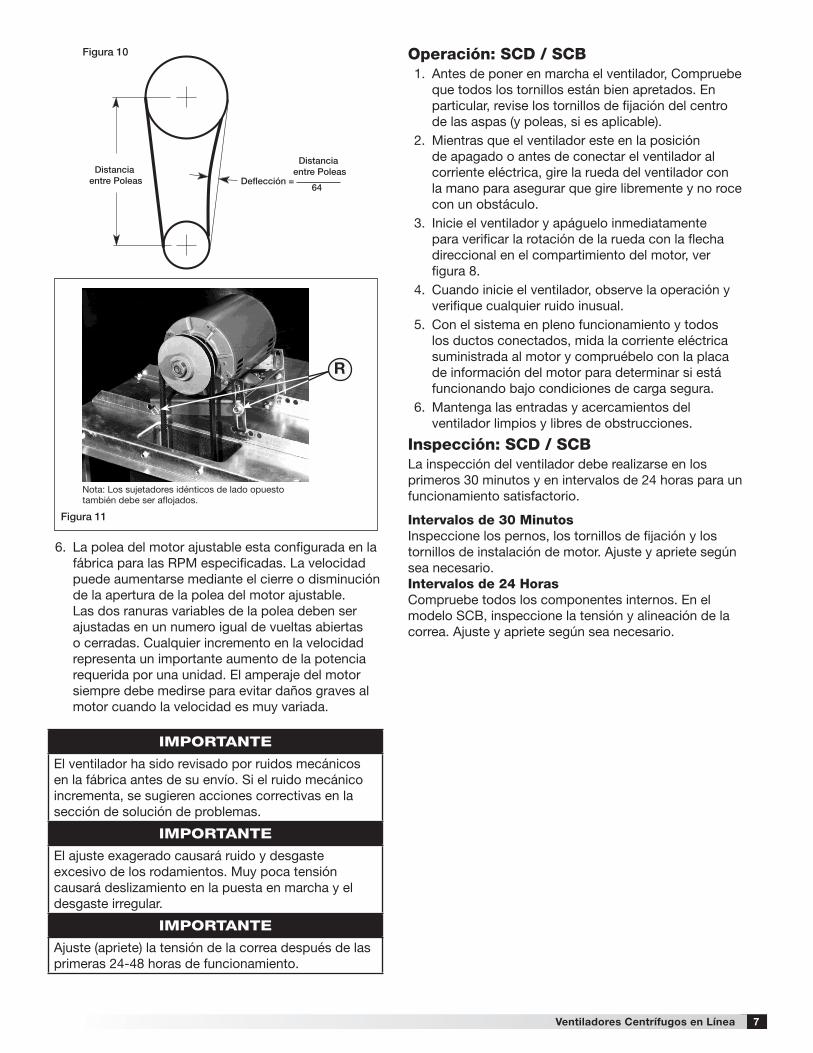
5. Para Ventiladores SCB: La tensión de la correapuede ajustarse aflojando los cuatro sujetadores marcados con una “R” en el marco de la unidad. (consulte la figura 11 en la página 7). La placa del motor se desliza en los rieles de ajuste. La tensión de la correa debe ser ajustada para permitir 1/64 pulgadas de deflexión por pulgada de la correa. Por ejemplo, un tramo de 15 pulgadas de correa debería tener 15/64 pulgadas (o aproximadamente 1/4 de pulgada) de deflexión moderada de presión con el dedo de la mano en el punto medio entre las poleas (ver figura 10). Si aprieta excesivamente causará ruido y desgaste excesivo en los rodamientos. Muy poca tensión causará deslizamiento en la puesta en marcha y desgaste irregular.
Dimensiones de Traslape de la Rueda
Figura 7
Modelo Traslape - G pulg. (mm)
Espacio - H pulg. (mm)
SCD 60-95 - 1/8 (3)SCD 100-160 1/4 (6) -SCB 70-160 1/4 (6) -SCB 180-240 3/8 (10) -SCB 300-420 1/2 (13) -SCD 97-98-99 1/4 (6) -
G
H
De
rec
ha
Figura 8
Figura 9
INCORRECTO INCORRECTO INCORRECTOCORRECTO
G
Clo
ck
wis
e
For BSQ Installation InstructionsImperialUsed in the USA
For BSQ-M Installation InstructionsMetricUsed in China
Belt Span
Deflection = Belt Span62.5
Deflección = 64
Distanciaentre Poleas
Distanciaentre Poleas
INCORRECTO INCORRECTO INCORRECTOCORRECTO
G
Clo
ck
wis
e
For BSQ Installation InstructionsImperialUsed in the USA
For BSQ-M Installation InstructionsMetricUsed in China
Belt Span
Deflection = Belt Span62.5
Deflección = 64
Distanciaentre Poleas
Distanciaentre Poleas
INCORRECTO INCORRECTO INCORRECTOCORRECTO
G
Clo
ck
wis
e
For BSQ Installation InstructionsImperialUsed in the USA
For BSQ-M Installation InstructionsMetricUsed in China
Belt Span
Deflection = Belt Span62.5
Deflección = 64
Distanciaentre Poleas
Distanciaentre Poleas
ADVERTENCIA
El correcto sentido de rotación de la rueda es crítico. La rotación invertida resultará con un rendimiento insuficiente de aire, sobrecarga del motor y posible sobrecalentamiento.
INCORRECTO INCORRECTO INCORRECTOCORRECTO
G
Clo
ck
wis
e
For BSQ Installation InstructionsImperialUsed in the USA
For BSQ-M Installation InstructionsMetricUsed in China
Belt Span
Deflection = Belt Span62.5
Deflección = 64
Distanciaentre Poleas
Distanciaentre Poleas
7Ventiladores Centrífugos en Línea
IMPORTANTE
El ventilador ha sido revisado por ruidos mecánicos en la fábrica antes de su envío. Si el ruido mecánico incrementa, se sugieren acciones correctivas en la sección de solución de problemas.
IMPORTANTE
El ajuste exagerado causará ruido y desgaste excesivo de los rodamientos. Muy poca tensión causará deslizamiento en la puesta en marcha y el desgaste irregular.
IMPORTANTE
Ajuste (apriete) la tensión de la correa después de las primeras 24-48 horas de funcionamiento.
6. La polea del motor ajustable esta configurada en lafábrica para las RPM especificadas. La velocidadpuede aumentarse mediante el cierre o disminuciónde la apertura de la polea del motor ajustable.Las dos ranuras variables de la polea deben serajustadas en un numero igual de vueltas abiertaso cerradas. Cualquier incremento en la velocidadrepresenta un importante aumento de la potenciarequerida por una unidad. El amperaje del motorsiempre debe medirse para evitar daños graves almotor cuando la velocidad es muy variada.
INCORRECTO INCORRECTO INCORRECTOCORRECTO
G
Clo
ck
wis
e
For BSQ Installation InstructionsImperialUsed in the USA
For BSQ-M Installation InstructionsMetricUsed in China
Belt Span
Deflection = Belt Span62.5
Deflección = 64
Distancia entre Poleas
Distancia entre Poleas
Figura 10
Figura 11
Nota: Los sujetadores idénticos de lado opuesto también debe ser aflojados.
R
Operación: SCD / SCB1. Antes de poner en marcha el ventilador, Compruebe
que todos los tornillos están bien apretados. Enparticular, revise los tornillos de fijación del centrode las aspas (y poleas, si es aplicable).
2. Mientras que el ventilador este en la posiciónde apagado o antes de conectar el ventilador alcorriente eléctrica, gire la rueda del ventilador conla mano para asegurar que gire libremente y no rocecon un obstáculo.
3. Inicie el ventilador y apáguelo inmediatamentepara verificar la rotación de la rueda con la flechadireccional en el compartimiento del motor, ver figura 8.
4. Cuando inicie el ventilador, observe la operación yverifique cualquier ruido inusual.
5. Con el sistema en pleno funcionamiento y todos los ductos conectados, mida la corriente eléctrica suministrada al motor y compruébelo con la placa de información del motor para determinar si está funcionando bajo condiciones de carga segura.
6. Mantenga las entradas y acercamientos delventilador limpios y libres de obstrucciones.
Inspección: SCD / SCBLa inspección del ventilador debe realizarse en los primeros 30 minutos y en intervalos de 24 horas para un funcionamiento satisfactorio.
Intervalos de 30 MinutosInspeccione los pernos, los tornillos de fijación y los tornillos de instalación de motor. Ajuste y apriete según sea necesario.Intervalos de 24 HorasCompruebe todos los componentes internos. En el modelo SCB, inspeccione la tensión y alineación de la correa. Ajuste y apriete según sea necesario.

8 Ventiladores Centrífugos en Línea
Mantenimiento: SCD / SCBLa instalación y mantenimiento deben realizarse solamente por personal calificado que esté familiarizado con las normas y reglamentos locales y que tienen experiencia con este tipo de equipos.
El mantenimiento del motor es generalmente limitada a la limpieza y lubricación (si procede). La limpieza debe limitarse a las superficies exteriores solamente. La eliminación de la acumulación de polvo en la cubierta del motor asegura una refrigeración adecuada del motor.
El engrase de los motores se limita únicamente cuando las boquillas de engrase son proporcionadas. Muchos motores de potencia fraccionaria están lubricados permanentemente y no deben ser lubricados después de la instalación. Los motores suministrados con boquillas deben engrasarse conforme a las recomendaciones del fabricante. Donde las temperaturas del motor no exceda a 40 ºC (104 ºF), la grasa debe reemplazarse después de 2.000 horas de duración como una regla general.
Las ruedas requieren muy poca atención cuando se mueve el aire limpio. En ocasiones, el aceite y el polvo pueden acumularse causando un desequilibrio. Cuando esto ocurra la rueda y la cubierta debe limpiarse para garantizar un funcionamiento suave y seguro.
Todos los sujetadores deben revisarse cada vez que se realice el mantenimiento y antes de reiniciar la unidad.
Un programa de mantenimiento adecuado ayudará a estas unidades a brindar años de servicio confiable.
PELIGRO
Siempre desconecte, bloquee y etiquete la fuente de energía antes de instalar o realizar mantenimiento. Si no se desconecta la fuente de energía, se puede provocar un incendio, descargas eléctricas o lesiones graves.
IMPORTANTE
Una limpieza irregular de la rueda producirá un desequilibrio que causará vibraciones en el ventilador.
ADVERTENCIA
Esta unidad debe apagada o sin corriente eléctrica cuando se realice un mantenimiento (remover los o desconectar la unidad).
Instalación y Removimiento del Cojinete Gradual del Centro de las AspasPara turbinas con aspas y poleas que utilizan una interfaz de cojinete gradual, siga este procedimiento para la instalación y removimiento. Hay dos opciones para el cojinete, ambos tienen el mismo procedimiento, pero la orientación del centro de las aspas varia.
Removimiento del Cojinete Gradual:1. (Si está presente): Aflojar el tornillo que sostiene el
cojinete y el eje.2. Aflojar y remover los tornillos que sujetan el cojinete
Instalación Estándar Instalación Reversa
Figura 14 Orientación Estándar
Figura 15Orientación Reversa
Figura 12 Figura 13
Cojinete
Cojinete
Rondanas
Rondanas
Tornillos
Tornillos
Centro de las Aspas
Centro de las Aspas
Cojinete
Cojinete
Rondanas
Rondanas
Tornillos
Tornillos
Centro de las Aspas
Centro de las Aspas
al centro de las aspas como se muestra en las figuras 12-15.
3. Instalación estándar: Instalar los dos tornillos en losorificios del centro de las aspas. Instalación Reversa: Instalar los dos tornillos en los orificios del cojinete.
4. Una vez que se instalan los dos tornillos, apretarlosun octavo de vuelta a la vez, alternando entre losdos hasta que el cojinete este bien ajustado alcentro de las aspas.
Instalación del Cojinete:1. Limpiar todas las superficies del cojinete y el centro
de las aspas y no utilice ningún lubricante parainstalar el cojinete en el centro. Para ambos tiposde instalación estándar y reverso, los tornillos sonajustables por la entrada del ventilador
2. Instalación estándar: deslice el cojinete en el eje delventilador seguido por la hélice y el centro de lasaspas. Si está presente, utilice el tornillo de fijaciónpara mantener el cojinete y el eje en su lugar perono apriete demasiado ya que esto puede dañar el

9Ventiladores Centrífugos en Línea
Mantenimiento de la Correa y Rodamientos del Modelo SCB1. Las correas tienden a estirarse después de un
período de tiempo. Estas deben ser revisadasperiódicamente para el desgaste y la tensión.Cuando reemplace las correas, utilice el mismo tiposuministrado con la unidad.
2. Las correas múltiples siempre deben utilizarse enlas unidades en poleas con ranuras múltiples.
3. Para reemplazar la correa, afloje el dispositivo detensión lo suficiente para permitir el retiro de lacorrea con la mano. No fuerce las correas al quitar oponer. Esto puede causar un daño y fallo prematurode la correa.
4. Una vez instaladas, ajuste las correas como seindica en “Revisiones antes de Comenzar”.
5. Los ejes de los rodamientos pueden clasificarse endos grupos: relubricantes y no relubricantes. Todoslos rodamientos de los ventiladores SCB estánlubricados en la fábrica y no requieren ningunalubricación adicional bajo un uso normal(entre - 30ºC y 82ºC en un ambiente relativamentelimpio).
6. Las unidades instaladas en lugares calientes,húmedos o sucios deben estar equipadas conrodamientos especiales. Estos rodamientosrequerirán lubricación frecuente. PRECAUCIÓNdebe emplearse para prevenir la contaminación o elexceso de grasa.
7. Las boquillas para engrasar deben estar limpias.La unidad debe estar en funcionamiento durantela lubricación. Debe utilizarse extremo cuidadoalrededor de las piezas móviles.
8. La grasa debe ser bombeada muy lentamente hastaque forme una gota pequeña alrededor del sello.Debe utilizarse una grasa con base de litio del altogrado.
Frecuencia de Lubricación Recomendada Nota: Si existen condiciones de ambiente extremo (temperaturas extremas, humedad o contaminantes) se requiere lubricación más frecuente.
Puede utilizar una buena calidad de grasa con base de litio, conforme a la consistencia NLGI grado 2, tales como los señalados aquí.
Fabricantes de Grasa
Fabricante Greasa (NLGI #2)
U.S. Electric Motors Grease No. 83343Chevron U.S.A. Inc Chevron SRI Grease #2
Mobil Oil CorporationMobilithMobil 532
Texaco, Inc.Premium BRB #2Texaco Multifak #2
Amoco Oil Co. Rykon Premium #2Exxon Unirex N2Shell B Shell Alvania #2
Sugerencia de Intervalos de Engrase
Intervalos (meses) Tipo de Servicio
1 a 3Pesados y en lugares sucios, polvorientos; temperaturas altas; atmósfera cargada de humedad; vibración.
3 a 612 a 24 horas por día, resistente, o si hay humedad presente
6 a 128 a 16 horas por día en un ambiente limpio y relativamente seco
12 a 18Operación poco frecuente o ligeros en ambiente limpio
cojinete. Alinear los orificios del cojinete con los orificios del centro de las aspas.
Instalación Reversa: Deslice la hélice y el centro de las aspas en el eje del ventilador seguido por el centro de las aspas. Si está presente, utilice el tornillo de fijación para mantener el eje y el cojinete en su lugar pero no apriete demasiado ya que esto puede dañar el cojinete. Alinear los orificios del centro de las aspas con los orificios del cojinete.
3. Instalar los dos tornillos con la mano (o sin torsiónexcesiva) hasta que las cabezas de los tornilloshagan contacto con la superficie.
4. Ajuste la altura de la rueda en el ventilador conrespecto a la entrada del Venturi y apriete los dostornillos a un octavo de vuelta de forma alterna y conuna torción de 10 pies/libra.
Los modelos incluidos en el manual de instalacion y mantenimiento son:
SCD75SP1301TA SCB100431O SCB160451O
SCD85SP1121TA SCB100451O SCB160471O
SCD90SP1101TA SCB100471O SCB1604101O
SCD95SP1101TA SCB1004101O SCB1604151O
SCD100441O SCB120441O SCB180431O
SCD120451O SCB120441O SCB180451O
SCD130471O SCB120451O SCB180471O
SCD1404101O SCB120471O SCB1804101O
SCD160651O SCB1204101O SCB1804151O
SCD100V410* SCB130441O SCB200431O
SCD120V510* SCB130431O SCB200451O
SCD140V101T* SCB130451O SCB200471O
SCD160V201T* SCB130471O SCB2004101O
SCB80441O SCB1304101O SCB2004151O
SCB80431O SCB1304151O SCB240451O
SCB80451O SCB140441O SCB240471O
SCB80471O SCB140431O SCB2404101O
SCB90441O SCB140451O SCB2404151O
SCB90431O SCB140471O SCB240451O
SCB90451O SCB1404101O SCB240471O
SCB90471O SCB1404151O SCB2404101O
SCB904101O SCB160441O SCB2404151O
SCB100441O SCB160431O SCD1604203O

Nuestro Compromiso
Como resultado de nuestra comisión de mejora continua, Globeaire reserva el derecho de cambiar especificaciones sin aviso.
[email protected] • globeaire.com
10 479713 • SCD/SCB, Rev. 1, julio 2016 Copyright 2016 © Globeaire
La publicación AMCA 410-96, Prácticas de seguridad para usuarios y personal de instalación de ventiladores industriales y comerciales, proporciona información de seguridad adicional. Esta publicación se puede obtener en AMCA International, Inc, en: www.amca.org.
PROBLEMA CAUSA ACCIÓN CORRECTIVA
Excesivo ruido o vibración
Desequilibrio de la ruedaLimpiar toda la suciedad de la rueda. Revisar la alineación de la rueda y alinear si es necesario.
Rodamientos dañados Reemplace.
Correa demasiado apretada o floja Ajuste la tensión, revise la figura 10.
Alineación inapropiada de la rueda Centre la rueda en la entrada, revise la figura 7.
Transmisión suelta o poleas flojasAlinea y apriete. Consulte “Revisiones antes de Comenzar”, revise la página 6-7.
Objetos extraños en la rueda o cubierta
Remover objetos, buscar daño o desequilibrio.
Flujo de Aire Insuficiente
Resistencia del sistema demasiado alta
Revise el sistema: Operación apropiada de las compuertas. obstrucción enlos ductos, limpiar los filtros.
Unidad funcionando al revés Corrija como se muestra en la Figura 8.
Acumulación de suciedad excesiva sobre ruedas
Limpie la rueda.
Alineación incorrectaCentre la rueda en la entrada, Consulte “Revisiones antes de Comenzar”, revise la página 7.
ADVERTENCIAAntes de tomar cualquier acción correctiva, asegúrese de unidad no es capaz de operar durante las reparaciones.
Problemas y Soluciones
Los modelos incluidos en el manual de instalacion y mantenimiento son:
SCB80443O SCB100453O SCB130473O SCB160433O SCB1804153O SCB240473O
SCB80433O SCB100473O SCB1304103O SCB160453O SCB1804203O SCB2404103O
SCB80453O SCB1004103O SCB1304153O SCB160473O SCB1804303O SCB2404153O
SCB80473O SCB140443O SCB140443O SCB1604103O SCB200433O SCB2404203O
SCB90443O SCB120443O SCB140433O SCB1604153O SCB200453O SCB2404303O
SCB90433O SCB120453O SCB140453O SCB1604203O SCB200473O SCB2404503O
SCB90453O SCB120473O SCB140473O SCB1604303O SCB2004103O
SCB90473O SCB1204103O SCB1404103O SCB180433O SCB2004153O
SCB904103O SCB130443O SCB1404153O SCB180453O SCB2004203O
SCB100443O SCB130433O SCB1404203O SCB180473O SCB2004303O
SCB100433O SCB130453O SCB160443O SCB1804103O SCB240453O

Centrifugal Inline Exhaust Fans 1
Installation, Operation and Maintenance ManualPlease read and save these instructions for future reference. Read carefully before attempting to assemble, install, operate or maintain the product described. Protect yourself and others by observing all safety information. Failure to comply with instructions could result in personal injury and/or property damage!
Document 479713Model SCD and SCB
Centrifugal Inline Fans
General Safety InformationOnly qualified personnel should install this fan. Personnel should have a clear understanding of these instructions and should be aware of general safety precautions. Improper installation can result in electric shock, possible injury due to coming in contact with moving parts, as well as other potential hazards. Other considerations may be required if seismic activity is present. If more information is needed, contact a licensed professional engineer before moving forward.
1. Follow all local electrical and safety codes, aswell as the National Electrical Code (NEC) and theNational Fire Protection Agency (NFPA), whereapplicable.
2. The rotation of the wheel is critical. It must be freeto rotate without striking or rubbing any stationaryobjects.
3. Motor must be securely and adequately grounded.4. Do not spin fan wheel faster than max cataloged fan
RPM. Adjustments to fan speed significantly effectsmotor load. If the fan RPM is changed, the motorcurrent should be checked to make sure it is notexceeding the motor nameplate amps.
5. Do not allow the power cable to kink or come incontact with oil, grease, hot surfaces or chemicals.Replace cord immediately if damaged.
6. Verify that the power source is compatible with theequipment.
7. Never open access doors to a duct while the fan isrunning.
Model SCD Direct DriveModel SCD is a direct drive centrifugal inline exhaust fan. These fans are specifically designed for inline applications. Each fan shall bear a permanently affixed manufacturers engraved metal nameplate containing the model number and individual serial number.
Model SCB Belt DriveModel SCB is a belt drive centrifugal inline exhaust fan. These fans are specifically designed for inline applications. Each fan shall bear a permanently affixed manufacturers engraved metal nameplate containing the model number and individual serial number.
DANGERAlways disconnect, lock and tag power source before installing or servicing. Failure to disconnect power source can result in fire, shock or serious injury.
CAUTIONWhen servicing the fan, motor may be hot enough to cause pain or injury. Allow motor to cool before servicing.
CAUTIONPrecaution should be taken in explosive atmospheres.
NOM WARNING
This product is not intended to be used by persons (including children) whos physical, sensory or mental capabilities are reduced, or with lack of experience or knowledge unless such persons are supervised or trained to operate the device.Children must be supervised to ensure they do not use this equipment as a toy.
IMPORTANT
If the power cord is damaged, it must be replaced by the manufacturer, its authorized service agent or by qualified personnel in oder to avoid hazard.

2 Centrifugal Inline Exhaust Fans
ReceivingUpon receiving the product check to ensure all items are accounted for by referencing the delivery receipt or packing list. Inspect each crate or carton for shipping damage before accepting delivery. Alert the carrier of any damage detected. The customer will make a notation of damage (or shortage of items) on the delivery receipt and all copies of the bill of lading which is countersigned by the delivering carrier. If damaged, immediately contact your local Representative. Any physical damage to the unit after acceptance is not the responsibility of the Manufacturer.
UnpackingVerify that all required parts and the correct quantity of each item have been received. If any items are missing, report shortages to your local representative to arrange for obtaining missing parts. Sometimes it is not possible that all items for the unit be shipped together due to availability of transportation and truck space. Confirmation of shipment(s) must be limited to only items on the bill of lading.
HandlingMove fan to desired location and determine position of access panels, discharge and motor. Make sure the inlet and outlet have at least 21/2 times the wheel diameter (duct diameter) before any obstructions like an elbow or transition. Attach the fan to a suitable framework as specified; hanging or base vibration isolators are recommended. See the SCD & SCB Fan Dimensions table on page 3 for physical dimensions, utilizing Figures 1 and 2. Mounting dimensions and vibration isolator centerline information is provided on pages 4 and 5. The motor’s amperage and voltage ratings must be checked for compatibility to supply voltage prior to final electrical connection. Electrical lead-in wires are then connected to the factory supplied safety disconnect switch. All wiring must conform to local and national codes.
Fan StorageFans are protected against damage during shipment. If the unit cannot be installed and operated immediately, precautions need to be taken to prevent deterioration of the unit during storage. The user assumes responsibility of the fan and accessories while in storage. The manufacturer will not be responsible for damage during storage. These suggestions are provided solely as a convenience to the user.
Indoor StorageThe ideal environment for the storage of fans and accessories is indoors, above grade, in a low humidity atmosphere which is sealed to prevent the entry of blowing dust, rain or snow. Temperatures should be evenly maintained between 30° to 110°F (-1° to 43°C) (wide temperature swings may cause condensation and “sweating” of metal parts). All accessories must be stored indoors in a clean, dry atmosphere.
Remove any accumulations of dirt, water, ice or snow
and wipe dry before moving to indoor storage. To avoid “sweating” of metal parts allow cold parts to reach room temperature. To dry parts and packages use a portable electric heater to get rid of any moisture buildup. Leave coverings loose to permit air circulation and to allow for periodic inspection.
The unit should be stored at least 31/2 in. (89 mm) off the floor on wooden blocks covered with moisture proof paper or polyethylene sheathing. Aisles between parts and along all walls should be provided to permit air circulation and space for inspection.
Outdoor StorageFans designed for outdoor applications may be stored outdoors, if absolutely necessary. Roads or aisles for portable cranes and hauling equipment are needed.
The fan should be placed on a level surface to prevent water from leaking into the fan. The fan should be elevated on an adequate number of wooden blocks so that it is above water and snow levels and has enough blocking to prevent it from settling into soft ground. Locate parts far enough apart to permit air circulation, sunlight and space for periodic inspection. To minimize water accumulation, place all fan parts on blocking supports so that rain water will run off.
Do not cover parts with plastic film or tarps as these cause condensation of moisture from the air passing through heating and cooling cycles.
Fan wheels should be blocked to prevent spinning caused by strong winds.
Inspection and Maintenance During StorageWhile in storage, inspect fans once per month. Keep a record of inspection and maintenance performed.
If moisture or dirt accumulations are found on parts, the source should be located and eliminated. At each inspection, rotate the wheel by hand ten to fifteen revolutions to distribute lubricant on motor. If paint deterioration begins, consideration should be given to touch-up or repainting. Fans with special coatings may require special techniques for touch-up or repair.
Machined parts coated with rust preventive should be restored to good condition promptly if signs of rust occur. Immediately remove the original rust preventive coating with petroleum solvent and clean with lint-free cloths. Polish any remaining rust from surface with crocus cloth or fine emery paper and oil. Do not destroy the continuity of the surfaces. Thoroughly wipe clean with Tectyl® 506 (Ashland Inc.) or the equivalent. For hard to reach internal surfaces or for occasional use, consider using Tectyl® 511M Rust Preventive, WD-40®
or the equivalent.
Removing From StorageAs fans are removed from storage to be installed in their final location, they should be protected and maintained in a similar fashion until the fan equipment goes into operation.

3Centrifugal Inline Exhaust Fans
SCD & SCB Fan DimensionsModel A B C *D E *F *G *H Damper SCD Weight^ SCB Weight^
SCD 60-75 12 (305) 13 (330) 12 (305) 87⁄8 (225) 1 (25) - - - 9 (229) 26 (12) -SCD 80-95 15 (381) 16 (406) 15 (381) 117⁄8 (302) 1 (25) - - - 12 (305) 41 (19) -SCD 97,98,99 15 (381) 21 (381) 15 (381) 117⁄8 (302) 1 (25) - - - 12 (305) 49 (22) -
SCD 100 17 (432) 21 (533) 17 (432) 137⁄8 (352) 1 (25) 151⁄2 (394) 14 (356) 121⁄2 (318) 14 (356) 56 (25) 83 (38)
SCD 120 19 (483) 21 (533) 19 (483) 157⁄8 (403) 1 (25) 177⁄8 (454) 16 (406) 121⁄2 (318) 16 (406) 67 (30) 97 (44)
SCD 130 (HP) 21 (533) 21 (533) 21 (533) 177⁄8 (454) 1 (25) 177⁄8 (454) 16 (406) 121⁄2 (318) 18 (457) 67 (35) 97 (44)
SCD 140 (HP) 23 (584) 22 (559) 23 (584) 197⁄8 (505) 1 (25) 177⁄8 (454) 16 (406) 121⁄2 (318) 20 (508) 104 (47) 111 (50)
SCD 160 (HP) 26 (660) 26 (660) 26 (660) 227⁄8 (581) 1 (25) 201⁄2 (521) 17 (432) 137⁄8 (340) 23 (584) 160 (73) 208 (94)
SCB 70-90 171⁄8 (435) 21 (533) 171⁄8 (435) 117⁄8 (302) 11⁄2 (37) 173⁄4 (394) 13 (330) 131⁄4 (327) 12 (305) - 106 (48)
SCB 100 171⁄8 (435) 21 (533) 171⁄8 (435) 137⁄8 (352) 11⁄2 (37) 173⁄4 (394) 13 (330) 131⁄4 (327) 14 (356) - 107 (48)
SCB 120 191⁄8 (486) 21 (533) 191⁄8 (486) 157⁄8 (403) 11⁄2 (37) 20 (508) 17 (432) 131⁄4 (327) 16 (406) - 124 (56)
SCB 130 (HP) 211⁄8 (537) 21 (533) 211⁄8 (537) 177⁄8 (454) 11⁄2 (37) 20 (508) 17 (432) 131⁄4 (327) 18 (457) - 131 (59)
SCB 140 (HP) 231⁄8 (587) 22 (559) 231⁄8 (587) 197⁄8 (504) 11⁄2 (37) 20 (508) 17 (432) 131⁄4 (327) 20 (508) - 146 (66)
SCB 160 (HP) 261⁄8 (664) 26 (660) 261⁄8 (664) 227⁄8 (581) 11⁄2 (37) 20 (508) 17 (432) 131⁄4 (327) 23 (584) - 188 (85)
SCB 180 (HP) 28 (711) 28 (711) 28 (711) 237⁄8 (606) 11⁄2 (38) 243⁄8 (619) 18 (457) 133⁄4 (349) 24 (610) - 245 (111)
SCB 200 (HP) 32 (813) 32 (813) 32 (813) 277⁄8 (708) 11⁄2 (38) 28 (711) 20 (508) 16 (406) 28 (711) - 314 (142
SCB 240 (HP) 39 (991) 34 (864) 39 (991) 347⁄8 (886) 11⁄2 (38) 327⁄8 (835) 22 (559) 19 (483) 35 (889) - 415 (188)
SCB 300 (HP) 46 (1168) 38 (965) 46 (1168) 417⁄8 (1064) 11⁄2 (38) 34 (864) 22 (559) 18 (457) 42 (1067) - 537 (244)
SCB 360 (HP) 52 (1321) 42 (1067) 52 (1321) 477⁄8 (1216) 11⁄2 (38) 34 (864) 22 (559) 18 (457) 48 (1219) - 686 (311)
SCB 420 (HP) 58 (1473) 50 (1270) 58 (1473) 537⁄8 (1368) 11⁄2 (38) 34 (864) 22 (559) 18 (457) 54 (1372) - 789 (358)All dimensions in inches (millimeters) and weight is shown in pounds (kilograms). *May be greater depending on motor. ^Weight shown is largest cataloged Open Drip Proof motor.
A A
BB
D
C C
F
D
E E
H
G
A A
BB
D
C C
F
D
E E
H
G
Figure 1: SCD Dimensions Figure 2:
SCB Dimensions
Mounting: SCD /SCB
All SCD and SCB fan models can be mounted horizontally, vertically or at an angle. For ease of installation, knockouts are provided at each location where mounting brackets are shown in Figures 3,4 and 5. Optional brackets are universally adjustable to mount in any of these locations.
Figure 3Horizontal Hanging or Base Mount
A
A
A
A
C
C
GB
B
B
B
G
D
DHanging rails
by others
Hanging rails by others
Figure 4Horizontal Hanging or Base Mount
A
A
A
A
C
C
GB
B
B
B
G
D
DHanging rails
by others
Hanging rails by others
With either a hanging or base mount the motor may be located on either side. The base mount allows top access panels only.

4 Centrifugal Inline Exhaust Fans
Mounting brackets are turned 90° for vertical mounting. Access panels are located on the two sides adjacent to the motor.
With a hanging mount, the motor may be located on either top or bottom. The base mount allows top motor location only. Both options provide access panels on two sides.
Mounting Dimensional DataModel A B C D E F G
SCD 60-75 105⁄8 (270) 163⁄4 (424) 145⁄8 (372) 87⁄8 (225) 197⁄8 (504) 67⁄8 (176)
Hanging rails not included.
Supplied by others.
SCD 80-95 131⁄4 (337) 193⁄4 (500) 151⁄8 (384) 93⁄8 (238) 43 (1092) 273⁄8 (695)
SCD 97, 98, 99 185⁄8 (473) 193⁄4 (500) 151⁄8 (384) 93⁄8 (238) 483⁄8 (1228) 273⁄8 (695)
SCD 100 185⁄8 (473) 213⁄4 (551) 195⁄8 (499) 137⁄8 (352) 433⁄4 (1112) 223⁄4 (579)
SCD 120 185⁄8 (473) 233⁄4 (602) 215⁄8 (549) 157⁄8 (403) 491⁄8 (1247) 281⁄8 (715)
SCD 130 185⁄8 (473) 253⁄4 (653) 235⁄8 (600) 177⁄8 (454) 44 (1118) 23 (584)
SCD 140 195⁄8 (498) 273⁄4 (704) 255⁄8 (651) 197⁄8 (505) 50 (1271) 28 (713)
SCD 160 231⁄2 (596) 31 (789) 283⁄4 (730) 227⁄8 (581) 491⁄2 (1257) 235⁄8 (601)
SCB 70-100 18 (457) 2113⁄16 (554) 1914⁄16 (505) 141⁄8 (359) 5014⁄16 (1292) 2914⁄16 (758)
Hanging rails not included.
Supplied by others.
SCB 120 18 (457) 2313⁄16 (605) 2114⁄16 (556) 161⁄8 (410) 553⁄4 (1416) 343⁄4 (883)
SCB 130 18 (457) 2513⁄16 (656) 2314⁄16 (607) 181⁄8 (460) 501⁄4 (1276) 291⁄4 (743)
SCB 140 19 (483) 2713⁄16 (707) 2514⁄16 (657) 201⁄8 (511) 56 (1424) 34 (865)
SCB 160 23 (584) 313⁄16 (792) 29 (737) 231⁄8 (587) 553⁄4 (1416) 293⁄4 (756)
SCB 180 25 (635) 323⁄16 (817) 30 (762) 241⁄8 (613) 573⁄4 (1467) 293⁄4 (756)
SCB 200 29 (737) 363⁄16 (919) 34 (864) 281⁄8 (714) 663⁄8 (1686) 343⁄8 (873)
SCB 240 31 (787) 433⁄16 (1097) 41 (1042) 351⁄8 (892) 681⁄2 (1740) 341⁄2 (876)
SCB 300 35 (889) 51 (1295) 463⁄4 (1188) 407⁄8 (1038) 691⁄8 (1755) 313⁄8 (797)
SCB 360 383⁄8 (1000) 57 (1449) 525⁄8 (1337) 463⁄4 (1187) 765⁄8 (1948) 343⁄4 (881)
SCB 420 47 (1195) 63 (1602) 585⁄8 (1488) 523⁄4 (1338) 901⁄4 (2292) 405⁄8 (1031)All dimensions in inches (millimeters).
Figure 5Vertical Hanging or Base Mount
A
A
A
A
C
C
GB
B
B
B
G
D
DHanging rails
by others
Hanging rails by others

5Centrifugal Inline Exhaust Fans
Side Discharge Duct Openings
Unit Size Width HeightSCB 70-80-90 117⁄8 (302) 117⁄8 (302)
SCD 60-75 97⁄8 (251) 87⁄8 (225)
SCD 80-95 127⁄8 (327) 117⁄8 (302)
SCD 97-98-99 137⁄8 (352) 117⁄8 (302)
SCD 100/SCB 100 137⁄8 (352) 137⁄8 (352)
SCD 120/SCB 120 157⁄8 (403) 157⁄8 (403)
SCD 130/SCB 130 (HP) 177⁄8 (454) 177⁄8 (454)
SCD 140/SCB 140 (HP) 197⁄8 (505) 197⁄8 (505)
SCD 160/SCB 160 (HP) 227⁄8 (581) 227⁄8 (581)
SCB 180 (HP) 237⁄8 (606) 237⁄8 (606)
SCB 200 (HP) 277⁄8 (708) 277⁄8 (708)
SCB 240 (HP) 287⁄8 (733) 347⁄8 (886)
SCB 300 (HP) 317⁄8 (810) 417⁄8 (1064)
SCB 360 (HP) 327⁄8 (835) 377⁄8 (962)
SCB 420 347⁄8 (886) 437⁄8 (1114)All dimensions in inches (millimeters).
Figure 6
Height
Left SideDischarge
Right SideDischarge
InlineDischarge
InletWidth
Duct Length: The inlet and outlet duct length should be approximately two to three wheel diameters long before and after the fan to achieve cataloged performance.
Side Discharge: Make sure discharge is orientated in the same direction as originally ordered, performance will change with different discharge positions. Refer to Figure 6 for proper side discharge definition and the Side Discharge chart for dimensions.
Standing Neoprene Isolator
Standing Spring Isolator
Hanging Neoprene IsolatorHanging Spring Isolator
Isolator Dimensional DataModel H I J K L
SCD 60-75
13⁄8 (35)
51⁄2 (140)
2 (51)
63⁄4 (171)
25⁄16 (59)
SCD 80-95SCD 97-99SCB 70-90SCD-SCB 100SCD-SCB 120SCD-SCB 130SCD-SCB 140
SCD-SCB 160
13⁄8 (35)
51⁄2 (140)
2 (51)
63⁄4 (171)
25⁄8 (67)
SCB 180SCB 200SCB 240SCB 300SCB 360SCB 420All dimensions in inches (millimeters).
K
H
J
STANDING SPRING
HANGING SPRING STANDING NEOPRENE
HANGING NEOPRENE
LH
J
I
H
J5/8 inch (16 mm)nominal
H
J
K
H
J
STANDING SPRING
HANGING SPRING STANDING NEOPRENE
HANGING NEOPRENE
LH
J
I
H
J5/8 inch (16 mm)nominal
H
J
K
H
J
STANDING SPRING
HANGING SPRING STANDING NEOPRENE
HANGING NEOPRENE
LH
J
I
H
J5/8 inch (16 mm)nominal
H
J
K
H
J
STANDING SPRING
HANGING SPRING STANDING NEOPRENE
HANGING NEOPRENE
LH
J
I
H
J5/8 inch (16 mm)nominal
H
J

6 Centrifugal Inline Exhaust Fans
Pre Start-Up Checks 1. Check all fasteners for tightness. The wheel should
rotate freely and be aligned as shown in Figure 7. Wheel position is preset and the unit is tested at the factory. Movement may occur during shipment, and realignment may be necessary. Centering can be accomplished by loosening the bolts holding the inlet (venturi) panel and repositioning. Wheel and inlet cone overlap can be adjusted by loosening the setscrews in the wheel and moving the wheel to the desired position.
2. Wheel Rotation: Direction of wheel rotation is critical. Reversed rotation will result in poor air performance, motor overloading and possible burnout. Check wheel rotation by momentarily energizing the unit (all SCD and SCB fans have clockwise wheel rotation when viewed from top of fan). Rotation should be clockwise as shown in Figure 8 and correspond to the rotation decal on the unit.
3. Vibration Isolators: After fan is moved to desired location, punch out the four knockout holes which are located on the unit top and bottom panels. Assemble the brackets to the unit according to the appropriate drawings on page 5 and refer to respective parts list on page 11. Make certain all connectors are tight and that all washers are in.
4. For SCB Fans: If adjustments are made, it is very important to check the pulleys for proper alignment. Misaligned pulleys lead to excessive belt wear, vibration, noise, and power loss. (see Figure 9).
5. For SCB Fans: Belt tension can be adjusted by loosening four fasteners marked “R” on the drive frame. (refer to Figure 11 on page 7). The motor plate slides on the slotted adjusting arms. Belt tension should be adjusted to allow 1/64 inch of deflection per inch of belt span. For example, a 15 inch belt span should have 15/64 inch (or about 1/4 inch) of deflection with moderate thumb pressure at mid-point between pulleys (see Figure 10). Over-tightening will cause excessive bearing wear and noise. Too little tension will cause slippage at start-up and uneven wear.
Wheel Overlap Dimensions
Figure 7
Model G - Overlap in. (mm)
H - Gap in. (mm)
SCD 60-95 - 1/8 (3)SCD 100-160 1/4 (6) -SCB 70-160 1/4 (6) -SCB 180-240 3/8 (10) -SCB 300-420 1/2 (13) -SCD 97-98-99 1/4 (6) -
G
H
Clo
ckw
ise
Figure 8
Figure 9
Belt SpanDeflection = Belt Span
64
WRONGWRONGWRONGCORRECT
G
Clo
ck
wis
e
For BSQ Installation InstructionsImperialUsed in the USA
For BSQ-M Installation InstructionsMetricUsed in China
Belt Span
Deflection = Belt Span62.5
Belt SpanDeflection = Belt Span
64
WRONGWRONGWRONGCORRECT
G
Clo
ck
wis
e
For BSQ Installation InstructionsImperialUsed in the USA
For BSQ-M Installation InstructionsMetricUsed in China
Belt Span
Deflection = Belt Span62.5
Belt SpanDeflection = Belt Span
64
WRONGWRONGWRONGCORRECT
G
Clo
ck
wis
e
For BSQ Installation InstructionsImperialUsed in the USA
For BSQ-M Installation InstructionsMetricUsed in China
Belt Span
Deflection = Belt Span62.5
WARNING
Correct direction of wheel rotation is critical. Reversed rotation will result in poor air performance, motor overloading and possible burnout.
Belt SpanDeflection = Belt Span
64
WRONGWRONGWRONGCORRECT
G
Clo
ck
wis
e
For BSQ Installation InstructionsImperialUsed in the USA
For BSQ-M Installation InstructionsMetricUsed in China
Belt Span
Deflection = Belt Span62.5

7Centrifugal Inline Exhaust Fans
IMPORTANT
The fan has been checked for mechanical noises at the factory prior to shipment. If mechanical noise should develop, suggested corrective actions are offered in the Troubleshooting section.
IMPORTANT
Over-tightening will cause excessive bearing wear and noise. Too little tension will cause slippage at start-up and uneven wear.
IMPORTANT
Adjust (tighten) belt tension after the first 24-48 hours of operation.
6. The adjustable motor pulley is factory set for the RPM specified. Speed can be increased by closing or decreased by opening the adjustable motor sheave. Two groove variable pitch pulleys must be adjusted an equal number of turns open or closed. Any increase in speed represents a substantial increase in the horsepower required by a unit. Motor amperage should always be checked to avoid serious damage to the motor when speed is varied.
Belt SpanDeflection = Belt Span
64
WRONGWRONGWRONGCORRECT
G
Clo
ck
wis
e
For BSQ Installation InstructionsImperialUsed in the USA
For BSQ-M Installation InstructionsMetricUsed in China
Belt Span
Deflection = Belt Span62.5
Figure 10
Figure 11
NOTE: Identical fasteners on opposing side must also be loosened.
R
Operation: SCD / SCB 1. Before starting up or operating fan, check all
fasteners for tightness. In particular, check the setscrews in wheel hub (and pulleys, if applicable).
2. While in the OFF position or before connecting the fan to power, turn the fan wheel by hand to be sure it is not striking the venturi or any obstacle.
3. Start the fan and shut it off immediately to check rotation of the wheel with directional arrow in the motor compartment, see Figure 8.
4. When the fan is started, observe the operation and check for any unusual noises.
5. With the system in full operation and all ductwork attached, measure current input to the motor and compare with the nameplate rating to determine if the motor is operating under safe load conditions.
6. Keep inlets and approaches to fan clean and free from obstruction.
Inspection: SCD / SCBInspection of the fan should be conducted at the first 30 minute and 24 hour intervals of satisfactory operation.
30 Minute IntervalInspect bolts, setscrews and motor mounting bolts. Adjust and tighten as necessary.
24 Hour IntervalCheck all internal components. On SCB unit only, inspect belt alignment and tension. Adjust and tighten as necessary.

8 Centrifugal Inline Exhaust Fans
Maintenance: SCD / SCBInstallation and maintenance are to be performed only by qualified personnel who are familiar with local codes and regulations and who are experienced with this type of equipment.
Motor maintenance is generally limited to cleaning and lubrication (where applicable). Cleaning should be limited to exterior surfaces only. Removing dust buildup on motor housing ensures proper motor cooling.
Greasing of motors is only intended when fittings are provided. Many fractional horsepower motors are permanently lubricated and should not be lubricated after installation. Motors supplied with grease fittings should be greased in accordance with manufacturers’ recommendations. Where motor temperatures do not exceed 104ºF (40ºC), the grease should be replaced after 2,000 hours of running time as a general rule.
Wheels require very little attention when moving clean air. Occasionally, oil and dust may accumulate causing imbalance. When this occurs the wheel and housing should be cleaned to ensure smooth and safe operation.
All fasteners should be checked for tightness each time maintenance checks are performed prior to restarting unit.
A proper maintenance program will help these units deliver years of dependable service.
DANGER
Always disconnect, lock and tag power source before servicing. Failure to disconnect power source can result in fire, shock or serious injury.
IMPORTANT
Uneven cleaning of the wheel will produce an out of balance condition that will cause vibration in the fan.
WARNING
This unit should be made non-functional when cleaning the wheel or housing (fuses removed, disconnect locked off).
Tapered Bushing Hub Installation and RemovalFor wheel hubs and shaft pulleys utilizing a tapered bushing interface, follow this procedure for installation and removal. There are two possible set ups for the tapered bushing, both have the same procedure, but orientation of the hub varies.
Tapered Bushing Removal:1. (If present): Loosen the setscrew holding the bushing
and shaft key in place.2. Loosen and remove the socket head cap screws
fastening the bushing to the hub as shown in the section views and examples of Figures 12-15.
3. Standard Mounting: Take the two socket head cap screws that were removed and install them into the visibly threaded holes on the wheel hub. Reverse Mounting: Install the two socket head cap screws into the visibly threaded holes of the bushing flange.
4. Once both socket head cap screws are installed, tighten them an eighth of a turn at a time, alternating between the two until the hub loosens from the bushing.
Bushing Installation:1. Clean all surfaces of hub and bushing to remove any
oil or residue present and do not use any lubricant to install bushing into the hub. For both standard and reverse mounting styles, the socket head cap screws are adjustable from the inlet of the fan.
2. Standard Mounting: Slide the bushing and shaft key onto the fan shaft followed by the wheel and hub assembly. If present, use the keyway setscrew to hold the shaft key and bushing in place but DO NOT overtighten as this can damage the bushing. Align
Standard Mounting Reverse Mounting
Figure 14 Standard Bushing Orientation
Figure 15Reverse Bushing Orientation
Figure 12 Figure 13
Bushing
Washers
Cap Screws
Hub
Bushing
Washers
Cap Screws
Hub
Bushing
Washers
Cap Screws
Hub
Bushing
Washers
Cap Screws
Hub

9Centrifugal Inline Exhaust Fans
Grease Manufacturers
Manufacturer Grease (NLGI #2)
U.S. Electric Motors Grease No. 83343Chevron U.S.A. Inc Chevron SRI Grease #2
Mobil Oil CorporationMobilithMobil 532
Texaco, Inc.Premium BRB #2Texaco Multifak #2
Amoco Oil Co. Rykon Premium #2Exxon Unirex N2Shell B Shell Alvania #2
Suggested Fan Bearing Greasing Intervals
Interval (months) Type of Service
1 to 3Heavy duty in dirty, dusty locations; high ambient temperatures; moisture laden atmosphere; vibration.
3 to 612 to 24 hours per day, heavy duty, or if moisture is present
6 to 128 to 16 hours per day in clean, relatively dry atmosphere
12 to 18Infrequent operation or light duty in clean atmosphere
Belt/Bearing Maintenance SCB Unit 1. Belts tend to stretch after a period of time. They
should be checked periodically for wear and tightness. When replacing belts, use the same type as supplied with the unit.
2. Matched belts should always be used on units with multi-groove pulleys.
3. For belt replacement, loosen the tensioning device enough to allow removal of the belt by hand. Do not force belts on or off. This may cause cords to break, leading to premature belt failure.
4. Once installed, adjust belts as shown in “Pre-Start-Up Checks.”
5. Shaft bearings can be classified in two groups: relubricating and non-relubricating. All bearings on standard model SCB fans are factory lubricated and require no further lubrication under normal use (between -20ºF and 180ºF in a relatively clean environment).
6. Units installed in hot, humid or dirty locations should be equipped with special bearings. These bearings will require frequent lubrication. Caution should be employed to prevent overpacking or contamination.
7. Grease fittings should be wiped clean. The unit should be in operation while lubricating. Extreme care should be used around moving parts.
8. Grease should be pumped in very slowly until a slight bead forms around the seal. A high grade lithium base grease should be used.
Recommended Relubrication Frequency in MonthsNOTE: If unusual environment conditions exist (extreme temperature, moisture or contaminants) more frequent lubrication is required.
A good quality lithium base grease, conforming to NLGI Grade 2 consistency, such as those listed here may be used.
the unthreaded holes of the hub with the threaded holes of the tapered bushing. Reverse Mounting: Slide the wheel and hub assembly onto the fan shaft followed by the bushing and shaft key. If present, use the keyway setscrew to hold the shaft key and bushing in place but DO NOT overtighten as this can damage the bushing. Align the unthreaded holes of the tapered bushing with the threaded holes of the hub.
3. Install the two bushing socket head cap screws into the aligned holes by hand (or without excessive torque) until the heads of the socket head cap screws are seated against the mating surface.
4. Adjust the height of the wheel in the fan relative to the inlet venturi then tighten the two socket head cap screws an eighth turn at a time in an alternating fashion and to a torque of 10 ft-lbs.
Models included in Installation Operation Manual are:
SCD75SP1301TA
SCD85SP1121TA
SCD90SP1101TA
SCD95SP1101TA
SCD100441O
SCD120451O
SCD130471O
SCD1404101O
SCD160651O
SCD100V410*
SCD120V510*
SCD140V101T*
SCD160V201T*
SCB80441O
SCB80431O
SCB80451O
SCB80471O
SCB90441O
SCB90431O
SCB90451O
SCB90471O
SCB904101O
SCB100441O
SCB100431O
SCB100451O
SCB100471O
SCB1004101O
SCB120441O
SCB120441O
SCB120451O
SCB120471O
SCB1204101O
SCB130441O
SCB130431O
SCB130451O
SCB130471O
SCB1304101O
SCB1304151O
SCB140441O
SCB140431O
SCB140451O
SCB140471O
SCB1404101O
SCB1404151O
SCB160441O
SCB160431O
SCB160451O
SCB160471O
SCB1604101O
SCB1604151O
SCB180431O
SCB180451O
SCB180471O
SCB1804101O
SCB1804151O
SCB200431O
SCB200451O
SCB200471O
SCB2004101O
SCB2004151O
SCB240451O
SCB240471O
SCB2404101O
SCB2404151O
SCB240451O
SCB240471O
SCB2404101O
SCB2404151O
SCD1604203O
SCB80443O
SCB80433O
SCB80453O
SCB80473O
SCB90443O
SCB90433O
SCB90453O
SCB90473O
SCB904103O
SCB100443O
SCB100433O
SCB100453O
SCB100473O
SCB1004103O
SCB140443O
SCB120443O
SCB120453O
SCB120473O

[email protected] • globeaire.com
AMCA Publication 410-96, Safety Practices for Users and Installers of Industrial and Commercial Fans, provides additional safety information. This publication can be obtained from AMCA International, Inc. at: www.amca.org.
As a result of our commitment to continuous improvement, Globeaire reserves the right to change specifications without notice.
10
Our Commitment
479713 • SCD/SCB • Rev. 1, July 2016 Copyright 2016 © Globeaire
PROBLEM CAUSE CORRECTIVE ACTION
Excessive noise or vibration
Wheel unbalanceClean all dirt off wheel. Check wheel balance, rebalance in place if necessary.
Bad bearings Replace.
Belts too tight or too loose Adjust tension, see Figure 10.
Wheel improperly aligned and rubbing
Center wheel on inlet, see Figure 7.
Loose drive or motor pulleys Align and tighten. See “Pre Start-Up Checks”, see page 6-7.
Foreign objects in wheel or housing
Remove objects, check for damage or unbalance.
Reduced airflow
System resistance too highCheck system: Proper operation of backdraft or control dampers, obstruction in ductwork, clean dirty filters.
Unit running backwards Correct as shown in Figure 8.
Excessive dirt buildup on wheels Clean wheel.
Improper wheel alignment Center wheel on inlets, see Pre Start-Up Checks and Figure 7.
WARNINGBefore taking any corrective action, make certain unit is not capable of operation during repairs.
Troubleshooting
SCB1204103O
SCB130443O
SCB130433O
SCB130453O
SCB130473O
SCB1304103O
SCB1304153O
SCB140443O
SCB140433O
SCB140453O
Models included in Installation Operation Manual are:
SCB140473O
SCB1404103O
SCB1404153O
SCB1404203O
SCB160443O
SCB160433O
SCB160453O
SCB160473O
SCB1604103O
SCB1604153O
SCB1604203O
SCB1604303O
SCB180433O
SCB180453O
SCB180473O
SCB1804103O
SCB1804153O
SCB1804203O
SCB1804303O
SCB200433O
SCB200453O
SCB200473O
SCB2004103O
SCB2004153O
SCB2004203O
SCB2004303O
SCB240453O
SCB240473O
SCB2404103O
SCB2404153O
SCB2404203O
SCB2404303O
SCB2404503O