k3fp -yv-i-i
TRANSCRIPT
7/29/2019 K3FP -YV-I-I
http://slidepdf.com/reader/full/k3fp-yv-i-i 1/411
CSM_K3FP_series_DS_E_3_1
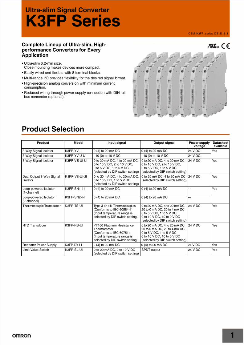
Ultra-slim Signal Converter
K3FP Series
Complete Lineup of Ultra-slim, High-performance Converters for EveryApplication
Ultra-slim 6.2-mm size.Close mounting makes devices more compact.
• Easily wired and flexible with 8 terminal blocks.
• Multi-range I/O provides flexibility for the desired signal format.
• High-precision analog conversion with minimum currentconsumption.
• Reduced wiring through power supply connection with DIN railbus connector (optional).
Product Selection
Product Model Input signal Output signal Power supplyvoltage
Datasheetavailable
3-Way Signal Isolator K3FP-YV-I-I 0 (4) to 20 mA DC 0 (4) to 20 mA DC 24 V DC Yes
3-Way Signal Isolator K3FP-YV-U-U −10 (0) to 10 V DC −10 (0) to 10 V DC 24 V DC
3-Way Signal Isolator K3FP-VS-UI-UI 0 to 20 mA DC, 4 to 20 mA DC,0 to 10 V DC, 2 to 10 V DC,0 to 5 V DC, 1 to 5 V DC(selected by DIP switch setting)
0 to 20 mA DC, 4 to 20 mA DC,0 to 10 V DC, 2 to 10 V DC,0 to 5 V DC, 1 to 5 V DC(selected by DIP switch setting)
24 V DC Yes
Dual Output 3-Way Signal
Isolator
K3FP-VS-UI-2I 0 to 20 mA DC, 4 to 20 mA DC,
0 to 10 V DC, 1 to 5 V DC(selected by DIP switch setting)
0 to 20 mA DC, 4 to 20 mA DC
(selected by DIP switch setting)
24 V DC Yes
Loop-powered Isolator(1-channel)
K3FP-SN1-I-I 0 (4) to 20 mA DC 0 (4) to 20 mA DC --- Yes
Loop-powered Isolator(2-channel)
K3FP-SN2-I-I 0 (4) to 20 mA DC 0 (4) to 20 mA DC ---
Thermocouple Transducer K3FP-TS-UI Type J and K Thermocouples(Conforms to IEC 60584-1)(Input temperature range isselected by DIP switch setting.)
0 to 20 mA DC, 4 to 20 mA DC,20 to 0 mA DC, 20 to 4 mA DC,0 to 5 V DC, 1 to 5 V DC,0 to 10 V DC, 10 to 0 V DC(selected by DIP switch setting)
24 V DC Yes
RTD Transducer K3FP-RS-UI PT100 Platinum ResistanceThermometer(Conforms to IEC 60751)(Input temperature range isselected by DIP switch setting.)
0 to 20 mA DC, 4 to 20 mA DC,20 to 0 mA DC, 20 to 4 mA DC,0 to 5 V DC, 1 to 5 V DC,0 to 10 V DC, 10 to 0 V DC(selected by DIP switch setting)
24 V DC Yes
Repeater Power Supply K3FP-DY-I-I 0 (4) to 20 mA DC 0 (4) to 20 mA DC 24 V DC Yes
Limit Value Switch K3FP-SL-UI 0 to 20 mA DC, 0 to 10 V DC(selected by DIP switch setting)
SPDT output 24 V DC Yes

7/29/2019 K3FP -YV-I-I
http://slidepdf.com/reader/full/k3fp-yv-i-i 2/41
K3FP Series
2
Applications
External device
2-conductor
PT100
3-conductor
PT100
4-conductor
PT100
Width: Just 6.2 mm.
Data Logger
Alarmindicator
Digital Panel Meter
Consider the following products for judging non-DC
signal inputs.For AC current single-phase signal inputs: K8AB-AS
For AC voltage single-phase signal inputs:
K8AB-VS/K8AB-VW
For AC voltage three-phase signal inputs: K8AB-PWFor thermocouple and platinum resistance
thermometer sensor inputs: K8AB-TH
Select the number of conductors for the input platinum resistancethermometer using the DIP switch on the side of the Unit.Set any input range from −150°C to 850°C.
The input signal provides power for the Isolator, so power supply
capacity does not need to be considered when expanding Units:
No power line wiring is required.
This ultra-slim 6.2-mm Signal Converter can be installed in limitedspace, such as where expansion is required, and help to reduce theoverall size of devices.
K3FP-RS-UI RTD TransducerK3FP-VS-UI-UI
Dual Output 3-Way Signal IsolatorK3FP-VS-UI-2I K3FP-SL-UI Limit Value Switch
Install in Limited Space Isolators That Do Not Require Power Supply
K3FP Series One-channel Passive Loop-powered IsolatorK3FP-SN1-I-ITwo-channel Passive Loop-powered IsolatorK3FP-SN2-I-I
Reduces Spare Parts Three- and four-conductor RTD Transducers
Isolated Duplicate Signal Output Limit Value Switches
Input and output ranges areset using a DIP switch onthe side of the Unit.
Output signal
0 to 10 V DC
2 to 10 V DC
0 to 5 V DC
1 to 5 V DC
0 to 20 mA DC
4 to 20 mA DC
Input signal
0 to 10 V DC
2 to 10 V DC
0 to 5 V DC
1 to 5 V DC
0 to 20 mA DC
4 to 20 mA DC
4 to 20 mA DC
4 to 20 mA DC
Input signal
0 to 20 mA DC,
4 to 20 mA DC,
0 to 10 V DC,
1 to 5 V DC
(switch usingDIP switch)
Field device
For details, refer to Measuring and Monitoring Relays K8AB Series/ 61F-D21T (Cat. No.: N141).
Note:
3-Way Signal Isolator

7/29/2019 K3FP -YV-I-I
http://slidepdf.com/reader/full/k3fp-yv-i-i 3/41
K3FP Series
3
In the interest of product improvement, specifications are subject to change without notice.
ALL DIMENSIONS SHOWN ARE IN MILLIMETERS.
To convert millimeters into inches, multiply by 0.03937. To convert grams into ounces, multiply by 0.03527.

7/29/2019 K3FP -YV-I-I
http://slidepdf.com/reader/full/k3fp-yv-i-i 4/411
3-Way Signal Isolator
K3FP-YV-I-I/K3FP-YV-U-U
6.2-mm Ultra-slim Isolator
• Isolates between input, output, and power supply. 1,500 V ACdielectric strength.
• Close mounting.
• CE Marking compliant.
• UL certified.
Refer to Safety Precautions for the K3FP Series .
Ordering Information
Isolator
Optional Products
Model Number Structure
DC Current Isolator
1. Model
2. Input or output signal
Current input
I: 0 (4) to 20 mA DC
Current output
I: 0 (4) to 20 mA DC
DC Voltage Isolator
1. Model
2. Input or output signal
Voltage input
U: −10 (0) to 10 V DC
Voltage output
U: −10 (0) to 10 V DC
Ratings and Specifications
Ratings and Specifications
Name Model
DC Current Isolator K3FP-YV-I-I
DC Voltage Isolator K3FP-YV-U-U
Name Model
DIN rail bus connector K3FP-1
1 2
K3FP-YV-I-I
1 2
K3FP-YV-U-U
Item Model K3FP-YV-I-I K3FP-YV-U-U
Supply voltage 24 V DC
Allowable supplyvoltage range
80% to 125% of rated supply voltage
Current consumption 20 mA DC max. 10 mA DC max.
Power consumption 450 mW max. 200 mW max.
Error ±0.1% FS max.
Temperaturecoefficient
Maximum: 0.01%/ °C max.,Typical: 0.002%/ °C max. (at 23°C)
Cut-off frequency 100 Hz
Response time(10% to 90%)
3.5 ms max.
Insulation resistance 10 MΩ min. between inputs, outputs, andpower supply (at 500 V DC)
Dielectric strength 1,500 V AC, 50 Hz, 1 min (between inputs,outputs, and power supply)
Noise resistance Conforms to IEC 61000
Ambient operatingtemperature
−20 to 65°C
Ambient storagetemperature
−40 to 85°C
Ambient operatinghumidity
95% max. (with no condensation)
Ambient storagehumidity
95% max. (with no condensation)
Connection method Screw connections (M3)Tightening torque 0.5 N·m
0
4
8
12
16
20
4 8 12 16 20
Input current (mA) Input voltage (V)
−10
10
0
−10100
K3FP-YV-I-I K3FP-YV-U-U
O u t p u t c u r r e n t
( m A )
O u t p u t v o l t a g
e ( V )

7/29/2019 K3FP -YV-I-I
http://slidepdf.com/reader/full/k3fp-yv-i-i 5/41
K3FP-YV-I-I/K3FP-YV-U-U
2
Input Specifications
Output Specifications
Nomenclature
Connections
Internal Block Diagram
Connectingcable
Solidwire
0.14 to 2.5 mm2
Strandedwire
0.2 to 2.5 mm2
AWG 24 to 12
Wirestrippinglength
12 mm
Degree of protection IP20
Housing material PBT
Weight 55 g
Safety standards UL 508
EMC EMI:
Radiated EMI: EN 55011
EMS:
ESD immunity: EN 61000-4-2
Rated electromagnetic field immunity:EN 61000-4-3
Burst immunity: EN 61000-4-4
Surge immunity: EN 61000-4-5
Conducted disturbance immunity:
EN 61000-4-6
Item Model K3FP-YV-I-I K3FP-YV-U-U
Input signalItem
0 (4) to 20 mA DC −10 (0) to 10 V DC
Input impedance Approx. 50 Ω Approx. 100 kΩ
Max. input signal 50 mA 30 V
Output signalItem
0 (4) to 20 mA DC −10 (0) to 10 V DC
Allowable loadimpedance
500 Ω max. 10 kΩ min.
Max. output signal 28 mA 12.5 V
Non-load voltage 12.5 V max. ---
Short-circuitcurrent
--- 22 mA max.
Ripple 20 mV pp max. (500 Ω) 20 mV pp max.
Span adjustmentrange
±0.5%
1 2 Input signals
3 4 Supply voltage
7 8 Supply voltage
5 6 Output signals
Translucent cover
Snap for mounting DIN rail
DIN rail bus connection
Potentiometer for adjustment
Note: The potentiometer is for adjustment at the factory. Do not adjust the potentiometer.
1
2
3
4
5
6
7
K3FP-1
8
−
+
−
+
Output signal
Supply voltage
Input signal
Supply voltage
−
+
−
+
Linking terminals Linking terminals

7/29/2019 K3FP -YV-I-I
http://slidepdf.com/reader/full/k3fp-yv-i-i 6/41
K3FP-YV-I-I/K3FP-YV-U-U
3
Dimensions
Note: All units are in millimeters unless otherwise indicated.
Safety Precautions
Refer to Safety Precautions for the K3FP Series .
93.1 6.2
102.5
K3FP-YV-I-I
K3FP-YV-U-U
Note: 1. Use solid wire with a diameterof 2.5 mm2 max. or barterminals with insulationsleeves for terminalconnections.To preserve dielectric strength
after connection, the length ofthe exposed conductive partinserted into the terminal mustbe 12 mm max.
2. Screw Tightening TorqueRecommended torque:0.5 N·m
12 mm max. 12 mm max.
For 2.5-mm2 (max.)solid wire:
For bar terminals withinsulation sleeves:
In the interest of product improvement, specifications are subject to change without notice.
ALL DIMENSIONS SHOWN ARE IN MILLIMETERS.
To convert millimeters into inches, multiply by 0.03937. To convert grams into ounces, multiply by 0.03527.
7/29/2019 K3FP -YV-I-I
http://slidepdf.com/reader/full/k3fp-yv-i-i 7/411
3-Way Signal Isolator
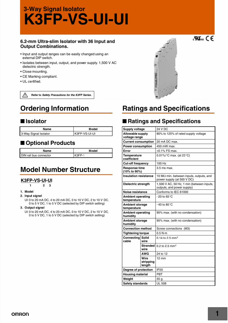
K3FP-VS-UI-UI
6.2-mm Ultra-slim Isolator with 36 Input andOutput Combinations.
• Input and output ranges can be easily changed using anexternal DIP switch.
• Isolates between input, output, and power supply. 1,500 V ACdielectric strength.
• Close mounting.
• CE Marking compliant.
• UL certified.
Refer to Safety Precautions for the K3FP Series .
Ordering Information
Isolator
Optional Products
Model Number Structure
1. Model
2. Input signal
UI:0 to 20 mA DC, 4 to 20 mA DC, 0 to 10 V DC, 2 to 10 V DC,0 to 5 V DC, 1 to 5 V DC (selected by DIP switch setting)
3. Output signal
UI:0 to 20 mA DC, 4 to 20 mA DC, 0 to 10 V DC, 2 to 10 V DC,0 to 5 V DC, 1 to 5 V DC (selected by DIP switch setting)
Ratings and Specifications
Ratings and Specifications
Name Model
3-Way Signal Isolator K3FP-VS-UI-UI
Name Model
DIN rail bus connector K3FP-1
1 2 3
K3FP-VS-UI-UI
Supply voltage 24 V DC
Allowable supplyvoltage range
80% to 125% of rated supply voltage
Current consumption 20 mA DC max.
Power consumption 450 mW max.
Error ±0.1% FS max.
Temperaturecoefficient
0.01%/ °C max. (at 23°C)
Cut-off frequency 100 Hz
Response time(10% to 90%)
3.5 ms max.
Insulation resistance 10 MΩ min. between inputs, outputs, andpower supply (at 500 V DC)
Dielectric strength 1,500 V AC, 50 Hz, 1 min (between inputs,outputs, and power supply)
Noise resistance Conforms to IEC 61000
Ambient operatingtemperature
−20 to 65°C
Ambient storagetemperature
−40 to 85°C
Ambient operatinghumidity
95% max. (with no condensation)
Ambient storagehumidity
95% max. (with no condensation)
Connection method Screw connections (M3)
Tightening torque 0.5 N·m
Connectingcable
Solidwire
0.14 to 2.5 mm2
Strandedwire
0.2 to 2.5 mm2
AWG 24 to 12
Wirestrippinglength
12 mm
Degree of protection IP20
Housing material PBT
Weight 55 g
Safety standards UL 508
7/29/2019 K3FP -YV-I-I
http://slidepdf.com/reader/full/k3fp-yv-i-i 8/41
K3FP-VS-UI-UI
2
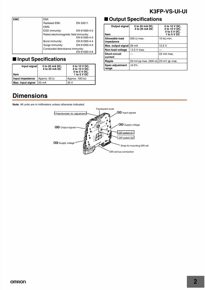
Input Specifications
Output Specifications
Dimensions
Note: All units are in millimeters unless otherwise indicated.
EMC EMI:
Radiated EMI: EN 55011
EMS:
ESD immunity: EN 61000-4-2
Rated electromagnetic field immunity:EN 61000-4-3
Burst immunity: EN 61000-4-4
Surge immunity: EN 61000-4-5
Conducted disturbance immunity:EN 61000-4-6
Input signal
Item
0 to 20 mA DC,4 to 20 mA DC
0 to 10 V DC,2 to 10 V DC,0 to 5 V DC,1 to 5 V DC
Input impedance Approx. 50 Ω Approx. 100 kΩ
Max. input signal 50 mA 30 V
Output signal
Item
0 to 20 mA DC,4 to 20 mA DC
0 to 10 V DC,2 to 10 V DC,0 to 5 V DC,1 to 5 V DC
Allowable loadimpedance
500 Ω max. 10 kΩ min.
Max. output signal 28 mA 12.5 V
Non-load voltage 12.5 V max. ---Short-circuitcurrent
--- 22 mA max.
Ripple 20 mV pp max. (500 Ω) 20 mV pp max.
Span adjustmentrange
±0.5%
DIP switch S1
DIP switch S2
1 2 Input signals
3 4 Supply voltage
7 8 Supply voltage
5 6 Output signals
Translucent cover
Snap for mounting DIN rail
DIN rail bus connection
Potentiometer for adjustment
7/29/2019 K3FP -YV-I-I
http://slidepdf.com/reader/full/k3fp-yv-i-i 9/41
K3FP-VS-UI-UI
3
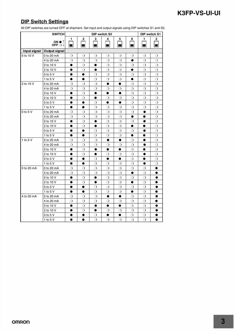
DIP Switch SettingsAll DIP switches are turned OFF at shipment. Set input and output signals using DIP switches S1 and S2.
SWITCH DIP switch S2 DIP switch S1
ON ↑OFF ↓
1 2 3 4 5 6 1 2
Input signal Output signal
0 to 10 V 0 to 20 mA
4 to 20 mA
0 to 10 V
2 to 10 V
0 to 5 V
1 to 5 V
2 to 10 V 0 to 20 mA
4 to 20 mA
0 to 10 V
2 to 10 V
0 to 5 V
1 to 5 V
0 to 5 V 0 to 20 mA
4 to 20 mA
0 to 10 V
2 to 10 V
0 to 5 V
1 to 5 V
1 to 5 V 0 to 20 mA
4 to 20 mA
0 to 10 V
2 to 10 V
0 to 5 V
1 to 5 V
0 to 20 mA 0 to 20 mA
4 to 20 mA
0 to 10 V
2 to 10 V
0 to 5 V
1 to 5 V
4 to 20 mA 0 to 20 mA
4 to 20 mA
0 to 10 V
2 to 10 V
0 to 5 V
1 to 5 V

7/29/2019 K3FP -YV-I-I
http://slidepdf.com/reader/full/k3fp-yv-i-i 10/41
K3FP-VS-UI-UI
4
Connections
Internal Block Diagram
Dimensions
Note: All units are in millimeters unless otherwise indicated.
Safety Precautions
Refer to Safety Precautions for the K3FP Series .
Precautions for Correct Use
Potentiometer The potentiometer for adjustment located under the translucent
cover can be used to make fine adjustments of analog signals afterDIP switch settings have been changed.
• The error when no adjustments have been made is less than 0.4%but if the potentiometer for adjustment is used, the error can bereduced to less than 0.1%.
1
2
3
4
5
6
7
8
Linking terminals
K3FP-1
Linking terminals
−
+
−
+
Output signal
Supply voltage
Input signal
Supply voltage
−
+
−
+
93.1 6.2
102.5
K3FP-VS-UI-UINote: 1. Use solid wire with a diameter
of 2.5 mm2 max. or barterminals with insulationsleeves for terminalconnections.To preserve dielectric strengthafter connection, the length ofthe exposed conductive partinserted into the terminal mustbe 12 mm max.
2. Screw Tightening TorqueRecommended torque:0.5 N·m
12 mm max. 12 mm max.
For 2.5-mm2 (max.)
solid wire:
For bar terminals with
insulation sleeves:
In the interest of product improvement, specifications are subject to change without notice.
ALL DIMENSIONS SHOWN ARE IN MILLIMETERS.
To convert millimeters into inches, multiply by 0.03937. To convert grams into ounces, multiply by 0.03527.
7/29/2019 K3FP -YV-I-I
http://slidepdf.com/reader/full/k3fp-yv-i-i 11/411
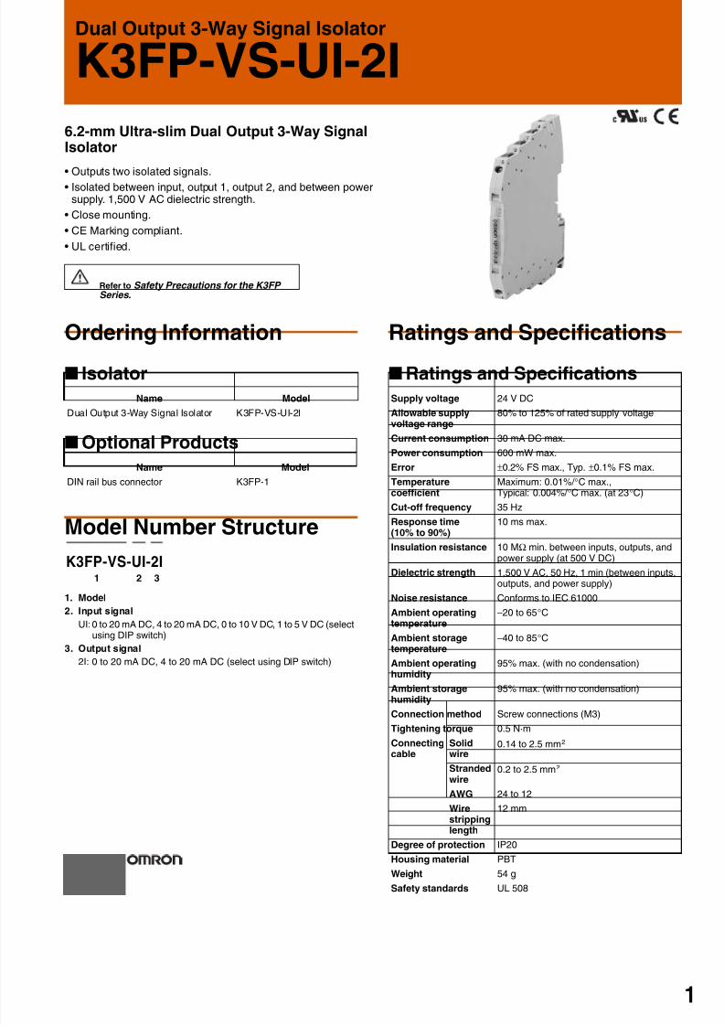
Dual Output 3-Way Signal Isolator
K3FP-VS-UI-2I
6.2-mm Ultra-slim Dual Output 3-Way SignalIsolator
• Outputs two isolated signals.
• Isolated between input, output 1, output 2, and between powersupply. 1,500 V AC dielectric strength.
• Close mounting.
• CE Marking compliant.
• UL certified.
Refer to Safety Precautions for the K3FP Series .
Ordering Information
Isolator
Optional Products
Model Number Structure
1. Model
2. Input signal
UI:0 to 20 mA DC, 4 to 20 mA DC, 0 to 10 V DC, 1 to 5 V DC (selectusing DIP switch)
3. Output signal
2I: 0 to 20 mA DC, 4 to 20 mA DC (select using DIP switch)
Ratings and Specifications
Ratings and Specifications
Name Model
Dual Output 3-Way Signal Isolator K3FP-VS-UI-2I
Name Model
DIN rail bus connector K3FP-1
1 2 3
K3FP-VS-UI-2I
Supply voltage 24 V DC
Allowable supplyvoltage range
80% to 125% of rated supply voltage
Current consumption 30 mA DC max.
Power consumption 600 mW max.
Error ±0.2% FS max., Typ. ±0.1% FS max.
Temperaturecoefficient
Maximum: 0.01%/ °C max.,Typical: 0.004%/ °C max. (at 23°C)
Cut-off frequency 35 Hz
Response time(10% to 90%)
10 ms max.
Insulation resistance 10 MΩ min. between inputs, outputs, andpower supply (at 500 V DC)
Dielectric strength 1,500 V AC, 50 Hz, 1 min (between inputs,outputs, and power supply)
Noise resistance Conforms to IEC 61000
Ambient operatingtemperature
−20 to 65°C
Ambient storagetemperature
−40 to 85°C
Ambient operatinghumidity
95% max. (with no condensation)
Ambient storagehumidity
95% max. (with no condensation)
Connection method Screw connections (M3)Tightening torque 0.5 N·m
Connectingcable
Solidwire
0.14 to 2.5 mm2
Strandedwire
0.2 to 2.5 mm2
AWG 24 to 12
Wirestrippinglength
12 mm
Degree of protection IP20
Housing material PBT
Weight 54 g
Safety standards UL 508
7/29/2019 K3FP -YV-I-I
http://slidepdf.com/reader/full/k3fp-yv-i-i 12/41
K3FP-VS-UI-2I
2
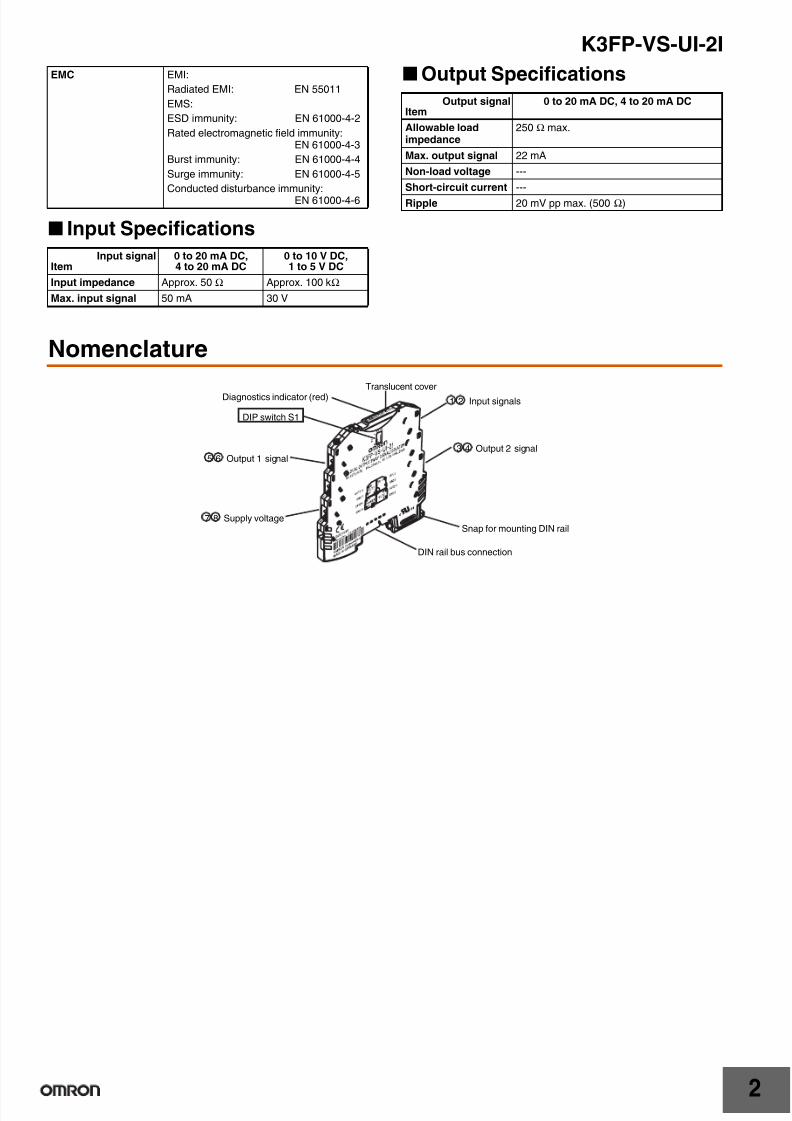
Input Specifications
Output Specifications
Nomenclature
EMC EMI:
Radiated EMI: EN 55011
EMS:
ESD immunity: EN 61000-4-2
Rated electromagnetic field immunity:EN 61000-4-3
Burst immunity: EN 61000-4-4
Surge immunity: EN 61000-4-5
Conducted disturbance immunity:EN 61000-4-6
Input signalItem
0 to 20 mA DC,4 to 20 mA DC
0 to 10 V DC,1 to 5 V DC
Input impedance Approx. 50 Ω Approx. 100 kΩ
Max. input signal 50 mA 30 V
Output signalItem
0 to 20 mA DC, 4 to 20 mA DC
Allowable loadimpedance
250 Ω max.
Max. output signal 22 mA
Non-load voltage ---
Short-circuit current ---
Ripple 20 mV pp max. (500 Ω)
Diagnostics indicator (red)
3 4 Output 2 signal5 6 Output 1 signal
DIP switch S1
1 2 Input signals
7 8 Supply voltage
Translucent cover
Snap for mounting DIN rail
DIN rail bus connection
7/29/2019 K3FP -YV-I-I
http://slidepdf.com/reader/full/k3fp-yv-i-i 13/41
K3FP-VS-UI-2I
3
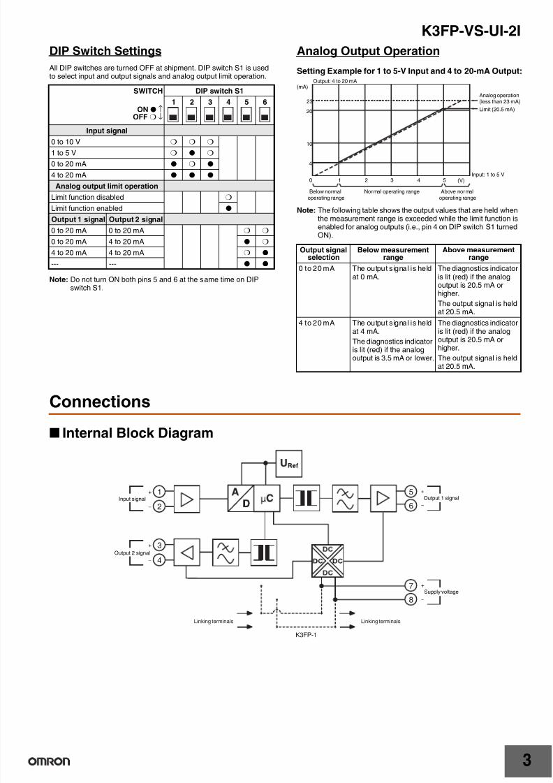
DIP Switch Settings
All DIP switches are turned OFF at shipment. DIP switch S1 is usedto select input and output signals and analog output limit operation.
Note: Do not turn ON both pins 5 and 6 at the same time on DIPswitch S1.
Analog Output Operation
Setting Example for 1 to 5-V Input and 4 to 20-mA Output:
Note: The following table shows the output values that are held whenthe measurement range is exceeded while the limit function isenabled for analog outputs (i.e., pin 4 on DIP switch S1 turnedON).
Connections
Internal Block Diagram
SWITCH DIP switch S1
ON ↑OFF ↓
1 2 3 4 5 6
Input signal
0 to 10 V
1 to 5 V
0 to 20 mA
4 to 20 mA
Analog output limit operation
Limit function disabled
Limit function enabled
Output 1 signal Output 2 signal
0 to 20 mA 0 to 20 mA
0 to 20 mA 4 to 20 mA
4 to 20 mA 4 to 20 mA
--- ---
Output signalselection
Below measurementrange
Above measurementrange
0 to 20 mA The output signal is held
at 0 mA.
The diagnostics indicator
is lit (red) if the analogoutput is 20.5 mA orhigher.
The output signal is heldat 20.5 mA.
4 to 20 mA The output signal is heldat 4 mA.
The diagnostics indicatoris lit (red) if the analogoutput is 3.5 mA or lower.
The diagnostics indicatoris lit (red) if the analogoutput is 20.5 mA orhigher.
The output signal is heldat 20.5 mA.
(mA)
23
Output: 4 to 20 mA
Below normaloperating range
Nor mal operating range Above nor maloperating range
Analog operation(less than 23 mA)
Limit (20.5 mA)
Input: 1 to 5 V
20
10
4
0 1 2 3 4 5 (V)
1
2
3
4
5
6
7
8
Linking terminalsLinking terminals
K3FP-1
Input signal
Output 2 signal
−
+
−
+
−
+
−
+
Output 1 signal
Supply voltage

7/29/2019 K3FP -YV-I-I
http://slidepdf.com/reader/full/k3fp-yv-i-i 14/41
K3FP-VS-UI-2I
4
Dimensions
Note: All units are in millimeters unless otherwise indicated.
Safety Precautions
Refer to Safety Precautions for the K3FP Series .
Precautions for Correct Use
Diagnostics Indicator
The diagnostics indicator (LED) inside the translucent cover lightswhen the input or output signal exceed the set range while the limitfunction is enabled (i.e., pin 4 on DIP switch S1 turned ON).
The diagnostics indicator flashes to indicate parameter memoryerrors. If this occurs, the Unit must be inspected at the factory.
93.1 6.2
102.5
K3FP-VS-UI-2INote: 1. Use solid wire with a diameter
of 2.5 mm2 max. or barterminals with insulationsleeves for terminalconnections.To preserve dielectric strength
after connection, the length ofthe exposed conductive partinserted into the terminal mustbe 12 mm max.
2. Screw Tightening TorqueRecommended torque:0.5 N·m
12 mm max. 12 mm max.
For 2.5-mm2 (max.)solid wire:
For bar terminals withinsulation sleeves:
In the interest of product improvement, specifications are subject to change without notice.
ALL DIMENSIONS SHOWN ARE IN MILLIMETERS.
To convert millimeters into inches, multiply by 0.03937. To convert grams into ounces, multiply by 0.03527.

7/29/2019 K3FP -YV-I-I
http://slidepdf.com/reader/full/k3fp-yv-i-i 15/411
Loop-powered Isolator
K3FP-SN1-I-I/K3FP-SN2-I-I
6.2-mm Ultra-slim Loop-powered Isolator
• Draws the power required to drive the amplifier from the inputcurrent signal.
• Isolated between input and output. 1,500 V AC dielectricstrength.
• Close mounting.
• CE Marking compliant.
• UL certified.
Refer to Safety Precautions for the K3FP Series .
Ordering Information Isolator
Optional Products
Model Number Structure
1. Model
SN1: Channel 1
SN2: Channel 2
2. Input signal
I: 0 (4) to 20 mA DC
3. Output signal
I: 0 (4) to 20 mA DC
Ratings and Specifications Ratings and Specifications
Name I/O signal Model
Loop-poweredIsolator
Channel 1 K3FP-SN1-I-I
Channel 2 K3FP-SN2-I-I
Name Model
DIN rail bus connector K3FP-1
1 2 3
K3FP-SN1-I-IK3FP-SN2-I-I
0
4
8
12
16
20
4 8 12 16 20
Input current (mA)
K3FP-SN@-I-I
O u t p u t c u r r e n t ( m A )
Item Model K3FP-SN1-I-I K3FP-SN2-I-I
Error ±0.1% FS max.
Other error per 100-Ω load
±0.03% of measured value max.
Temperaturecoefficient per 100-Ω load
±0.002% of measured value max. (at 23°C)
Cut-off frequency 75 Hz (3 dB)
Response time (10%to 90%)
5 ms max. (for a 600-Ω load)
Insulation resistance 10 MΩ min. between inputs, outputs, andpower supply (at 500 V DC)
Dielectric strength 1,500 V AC, 50 Hz, 1 min (between inputs,outputs, and power supply)
Noise resistance Conforms to IEC 61000
Ambient operatingtemperature
−20 to 65°C
Ambient storagetemperature
−40 to 85°C
Ambient operatinghumidity
95% max. (with no condensation)
Ambient storagehumidity
95% max. (with no condensation)
Connection method Screw connections (M3)
Tightening torque 0.5 N·m
Connectingcable
Solidwire
0.14 to 2.5 mm2
Strandedwire
0.2 to 2.5 mm2
AWG 24 to 12
Wirestrippinglength
12 mm
Degree of protection IP20
Housing material PBT
Weight 54 g 58 g
Safety standards UL 508
7/29/2019 K3FP -YV-I-I
http://slidepdf.com/reader/full/k3fp-yv-i-i 16/41
K3FP-SN1-I-I/K3FP-SN2-I-I
2
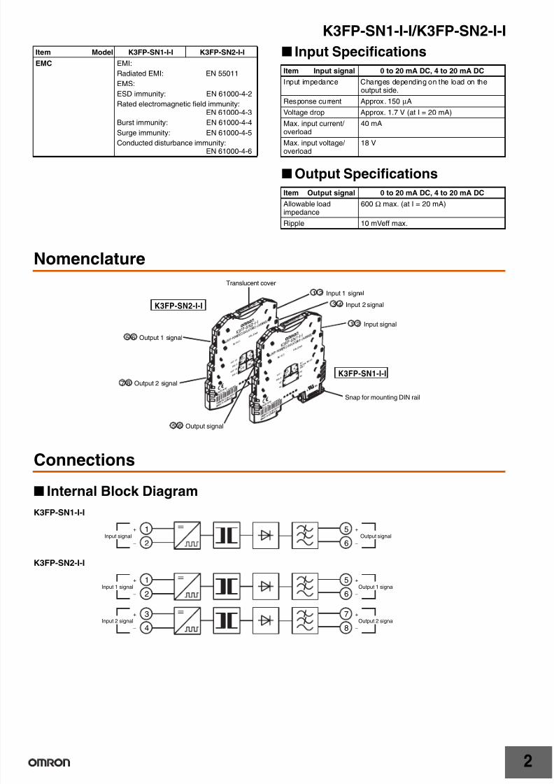
Input Specifications
Output Specifications
Nomenclature
Connections
Internal Block Diagram
K3FP-SN1-I-I
K3FP-SN2-I-I
EMC EMI:
Radiated EMI: EN 55011
EMS:
ESD immunity: EN 61000-4-2
Rated electromagnetic field immunity:EN 61000-4-3
Burst immunity: EN 61000-4-4
Surge immunity: EN 61000-4-5
Conducted disturbance immunity:EN 61000-4-6
Item Model K3FP-SN1-I-I K3FP-SN2-I-I
Item Input signal 0 to 20 mA DC, 4 to 20 mA DC
Input impedance Changes depending on the load on theoutput side.
Response current Approx. 150 µA
Voltage drop Approx. 1.7 V (at I = 20 mA)
Max. input current/ overload
40 mA
Max. input voltage/ overload
18 V
Item Output signal 0 to 20 mA DC, 4 to 20 mA DC
Allowable loadimpedance
600 Ω max. (at I = 20 mA)
Ripple 10 mVeff max.
1 2 Input signal
Snap for mounting DIN rail
5 6 Output signal
3 4 Input 2 signal
1 2 Input 1 signal
5 6 Output 1 signal
7 8 Output 2 signal
K3FP-SN1-I-I
K3FP-SN2-I-I
Translucent cover
1
2
5
6Input signal
−
+
−
+
Output signal
1
2
5
6−
+
−
+
Output 1 signal
3
4
7
8
Input 1 signal
Input 2 signal
−
+
−
+
Output 2 signal

7/29/2019 K3FP -YV-I-I
http://slidepdf.com/reader/full/k3fp-yv-i-i 17/41
K3FP-SN1-I-I/K3FP-SN2-I-I
3
Dimensions
Note: All units are in millimeters unless otherwise indicated.
Safety Precautions
Refer to Safety Precautions for the K3FP Series .
Precautions for Correct Use
Operation
Passive Loop-powered Isolators draw the power required for isolationfrom the input signal.
Here, you must confirm that the current sourcing voltage of themeasuring transducer UB is sufficient to drive the maximum currentof 20 mA via the Loop-powered Isolator with a voltage drop UV of1.7 V and a load RB.
Thus:
UB ≥ UE = 1.7 V + 20 mA × RB
93.1 6.2
102.5
K3FP-SN1-I-I
K3FP-SN2-I-I
Note: 1. Use solid wire with a diameterof 2.5 mm2 max. or barterminals with insulationsleeves for terminalconnections.To preserve dielectric strength
after connection, the length ofthe exposed conductive partinserted into the terminal mustbe 12 mm max.
2. Screw Tightening TorqueRecommended torque:0.5 N·m
12 mm max. 12 mm max.
For 2.5-mm2 (max.)solid wire:
For bar terminals withinsulation sleeves:
UV = 1.7 V
K3FP-SN1-I-I
In the interest of product improvement, specifications are subject to change without notice.
ALL DIMENSIONS SHOWN ARE IN MILLIMETERS.
To convert millimeters into inches, multiply by 0.03937. To convert grams into ounces, multiply by 0.03527.

7/29/2019 K3FP -YV-I-I
http://slidepdf.com/reader/full/k3fp-yv-i-i 18/411
Thermocouple Transducer
K3FP-TS-UI
6.2-mm Ultra-slim Thermocouple Transducer
• Converts measured values for type J and K thermocouplesensors into analog signals.
• Measurement range can be set between −150 and 1,350°C.
• Isolates between input, output, and power supply. 1,500 V ACdielectric strength.
• Close mounting.
• CE Marking compliant.
• UL certified.
Refer to Safety Precautions for the K3FP Series .
Ordering Information
Thermocouple Transducer
Optional Products
Model Number Structure
1. Model
Type J and K Thermocouples(Conforms to IEC 60584-1)
2. Output signal
UI: 0 to 20 mA DC, 4 to 20 mA DC,20 to 0 mA DC, 20 to 4 mA DC,0 to 5 V DC, 1 to 5 V DC,0 to 10 V DC, 10 to 0 V DC(selected by DIP switch setting)
Ratings and Specifications
Ratings and Specifications
Note: 1. Example: Error for a Setting of −30 to 100°C(100/130) + 0.1 = 0.76 + 0.1 = 0.869%, 130°C × 0.87% =1.13°C* Here, the "standard error measurement range overall" isfor −150°C to 1,350°C.
2. K is the abbreviation for Kelvin, the unit for absolutetemperature.
Name Model
Thermocouple Transducer K3FP-TS-UI
Name Model
DIN rail bus connector K3FP-1
1 2
K3FP-TS-UI
Supply voltage 24 V DC
Allowable supply voltage range 80% to 125% of rated supply voltage
Current consumption 25 mA DC max.
Power consumption 500 mW max.
Error (See note.) Within set measurement range: ((150 K/setmeasurement range [K]) + 0.1)%(Standard error measurement rangeoverall: ±0.2% FS max.)
Temperature coefficient Max. 0.02%/ °C max. (at 23°C)
Cold junction error 3 K (average 2 K)
Response time (0% to 99%) 30 ms max.
Insulation resistance 10 MW min. between inputs, outputs, andpower supply (at 500 V DC)
Dielectric strength 1,500 V AC, 50 Hz, 1 min (between inputs,outputs, and power supply)
Noise resistance Conforms to IEC 61000
Ambient operating temperature −20 to 65°C
Ambient storage temperature −40 to 85°C
Ambient operating humidity 95% max. (with no condensation)
Ambient storage humidity 95% max. (with no condensation)
Connection method Screw connections (M3)
Tightening torque 0.5 N·m
Con-nectingcable
Solid wire 0.14 to 2.5 mm2
Stranded wire 0.2 to 2.5 mm2
AWG 24 to 12
Wire stripping length 12 mm
Degree of protection IP20
Housing material PBT
Weight 54 g
Safety standards UL 508
EMC EMI:Radiated EMI: EN 55011EMS:ESD immunity: EN 61000-4-2Rated electromagnetic field immunity:
EN 61000-4-3Burst immunity: EN 61000-4-4Surge immunity: EN 61000-4-5Conducted disturbance immunity:
EN 61000-4-6
7/29/2019 K3FP -YV-I-I
http://slidepdf.com/reader/full/k3fp-yv-i-i 19/41
K3FP-TS-UI
2
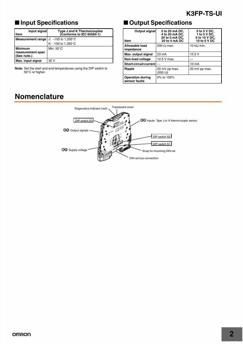
Input Specifications
Note: Set the start and end temperatures using the DIP switch to50°C or higher.
Output Specifications
Nomenclature
Input signalItem
Type J and K Thermocouples(Conforms to IEC 60584-1)
Measurement range J: −150 to 1,200°CK: −150 to 1,350°C
Minimummeasurement span(See note.)
Min. 50°C
Max. input signal 30 V
Output signal
Item
0 to 20 mA DC,4 to 20 mA DC,20 to 0 mA DC,20 to 4 mA DC
0 to 5 V DC,1 to 5 V DC,
0 to 10 V DC,10 to 0 V DC
Allowable loadimpedance
500 Ω max. 10 kΩ min.
Max. output signal 23 mA 12.5 V
Non-load voltage 12.5 V max. ---Short-circuit current --- 10 mA
Ripple 20 mV pp max.(500 Ω)
20 mV pp max.
Operation duringsensor faults
0% to 105%
7 8 Supply voltage
5 6 Output signals
Translucent cover
Snap for mounting DIN rail
DIN rail bus connection
Diagnostics indicator (red)
DIP switch S3
DIP switch S2
DIP switch S1
2 3 Inputs: Type J or K thermocouple sensor
7/29/2019 K3FP -YV-I-I
http://slidepdf.com/reader/full/k3fp-yv-i-i 20/41
K3FP-TS-UI
3
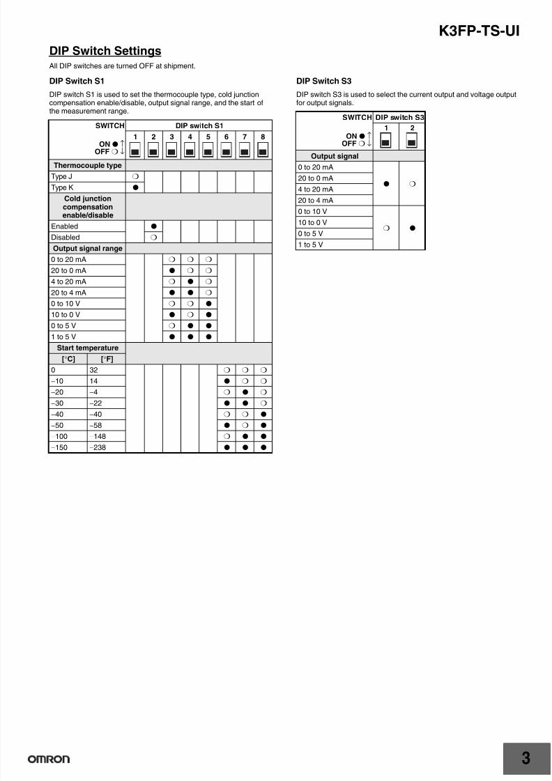
DIP Switch SettingsAll DIP switches are turned OFF at shipment.
DIP Switch S1
DIP switch S1 is used to set the thermocouple type, cold junctioncompensation enable/disable, output signal range, and the start ofthe measurement range.
DIP Switch S3
DIP switch S3 is used to select the current output and voltage outputfor output signals.
SWITCH DIP switch S1
ON ↑OFF ↓
1 2 3 4 5 6 7 8
Thermocouple type
Type J
Type K
Cold junctioncompensationenable/disable
Enabled
Disabled
Output signal range
0 to 20 mA
20 to 0 mA
4 to 20 mA
20 to 4 mA
0 to 10 V
10 to 0 V
0 to 5 V
1 to 5 V
Start temperature
[°C] [°F]
0 32
−10 14
−20 −4
−30 −22
−40 −40
−50 −58
−100 −148
−150 −238
SWITCH DIP switch S3
ON ↑OFF ↓
1 2
Output signal
0 to 20 mA
20 to 0 mA
4 to 20 mA
20 to 4 mA
0 to 10 V
10 to 0 V
0 to 5 V
1 to 5 V

7/29/2019 K3FP -YV-I-I
http://slidepdf.com/reader/full/k3fp-yv-i-i 21/41
K3FP-TS-UI
4
DIP Switch S2
DIP switch S2 is used to select the measurement range end value and output status for errors.
Note: Type J supports up to 1,200°C and type K supports up to 1,350°C.
SWITCH DIP switch S2
ON ↑OFF ↓
1 2 3 4 5 6 7 8
End temperature
[°C] [°F]0 32
10 50
20 68
30 86
40 104
50 122
60 140
70 158
80 176
90 194
100 212
110 230
120 248
130 266
140 284
150 302
160 320
170 338
180 356
190 374
200 392
210 410
220 428
230 446
240 464
250 482
260 500
270 518
280 536
290 554
300 572
320 608
Output status forerrors
A
B
C
D
SWITCH DIP switch S2
ON ↑OFF ↓
1 2 3 4 5 6 7 8
End temperature
[°C] [°F]340 644
360 680
380 716
400 752
420 788
440 824
460 860
480 896
500 932
520 968
540 1004
560 1040
580 1076
600 1112
620 1148
640 1184
660 1220
680 1256
700 1292
750 1382
800 1472
850 1562
900 1652
950 1742
1000 1832
1050 1922
1100 2012
1150 2102
1200 2192
1250 (Seenote.)
2282
1300 (Seenote.)
2372
1350 (Seenote.)
2462
Output status forerrors
A
B
C
D

7/29/2019 K3FP -YV-I-I
http://slidepdf.com/reader/full/k3fp-yv-i-i 22/41
K3FP-TS-UI
5
Output Status for Errors
Relationship between Output Signal Range Selection
Output Signal Ranges 0 to 20 mA or 20 to 0 mA
Output Signal Ranges 4 to 20 mA or 20 to 4 mA
Output Signal Ranges 0 to 10 V or 10 to 0 V
Output Signal Range 0 to 5 V
Output Signal Range 1 to 5 V
SWITCH DIP switch S2
ON ↑OFF ↓
7 8
Output statusfor errors
When disconnected onthermocouple side
Above measurement range Below measurement range
A Held at 5% of maximum rated
output.
Held at 2.5% of maximum rated
output.
Held at minimum rated output.
B Held at 5% of maximum ratedoutput.
Held at 2.5% of maximum ratedoutput.
Held at −12.5% of minimum ratedoutput.
C Held at 5% of maximum ratedoutput.
Held at maximum rated output. Held at minimum rated output.
D Held at minimum rated output. Held at maximum rated output. Held at minimum rated output.
Output statusfor errors
DIP switch S2 When disconnected onthermocouple side
Above measurement range Below measurement range
7 8
A 21 mA 20.5 mA 0 mA
B 21 mA 20.5 mA 0 mAC 21 mA 20 mA 0 mA
D 0 mA 20 mA 0 mA
Output statusfor errors
DIP switch S2 When disconnected onthermocouple side
Above measurement range Below measurement range
7 8
A 21 mA 20.5 mA 4 mA
B 21 mA 20.5 mA 3.5 mA
C 21 mA 20 mA 4 mA
D 4 mA 20 mA 4 mA
Output statusfor errors
DIP switch S2 When disconnected onthermocouple side
Above measurement range Below measurement range
7 8
A 10.5 V 10.25 V 0 V
B 10.5 V 10.25 V 0 V
C 10.5 V 10 V 0 V
D 0 V 10 V 0 V
Output statusfor errors
DIP switch S2 When disconnected onthermocouple side
Above measurement range Below measurement range
7 8
A 5.25 V 5.125 V 0 V
B 5.25 V 5.125 V 0 V
C 5.25 V 5 V 0 V
D 0 V 5 V 0 V
Output statusfor errors
DIP switch S2 When disconnected onthermocouple side
Above measurement range Below measurement range
7 8
A 5.25 V 5.125 V 1 V
B 5.25 V 5.125 V 0.875 V
C 5.25 V 5 V 1 V
D 1 V 5 V 1 V
7/29/2019 K3FP -YV-I-I
http://slidepdf.com/reader/full/k3fp-yv-i-i 23/41
K3FP-TS-UI
6
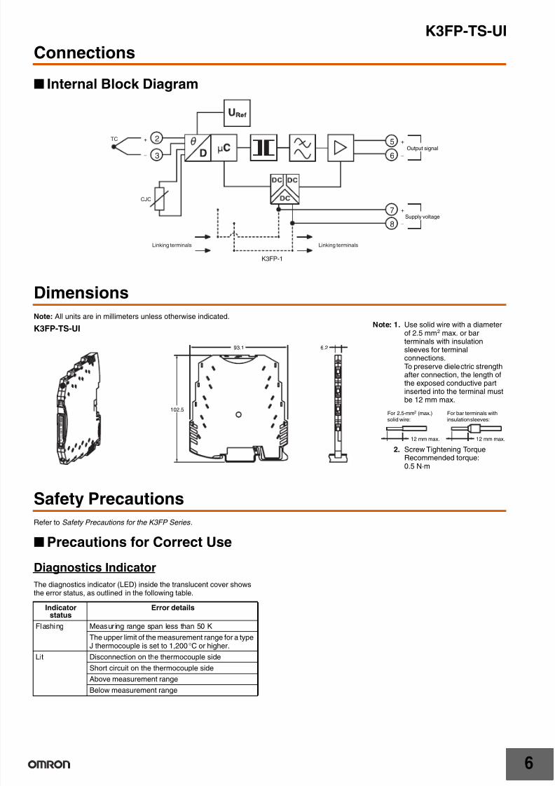
Connections
Internal Block Diagram
Dimensions
Note: All units are in millimeters unless otherwise indicated.
Safety Precautions
Refer to Safety Precautions for the K3FP Series .
Precautions for Correct Use
Diagnostics Indicator
The diagnostics indicator (LED) inside the translucent cover showsthe error status, as outlined in the following table.
2
3
TC
CJC
5
6
7
8
−
+
Linking terminalsLinking terminals
K3FP-1
−
+
Output signal
−
+
Supply voltage
93.1 6.2
102.5
K3FP-TS-UINote: 1. Use solid wire with a diameter
of 2.5 mm2 max. or barterminals with insulationsleeves for terminalconnections.To preserve dielectric strengthafter connection, the length ofthe exposed conductive partinserted into the terminal mustbe 12 mm max.
2. Screw Tightening TorqueRecommended torque:0.5 N·m
12 mm max. 12 mm max.
For 2.5-mm2 (max.)solid wire:
For bar terminals withinsulation sleeves:
Indicatorstatus
Error details
Flashing Measuring range span less than 50 K
The upper limit of the measurement range for a typeJ thermocouple is set to 1,200°C or higher.
Lit Disconnection on the thermocouple side
Short circuit on the thermocouple side
Above measurement range
Below measurement range

7/29/2019 K3FP -YV-I-I
http://slidepdf.com/reader/full/k3fp-yv-i-i 24/41
K3FP-TS-UI
7
In the interest of product improvement, specifications are subject to change without notice.
ALL DIMENSIONS SHOWN ARE IN MILLIMETERS.
To convert millimeters into inches, multiply by 0.03937. To convert grams into ounces, multiply by 0.03527.

7/29/2019 K3FP -YV-I-I
http://slidepdf.com/reader/full/k3fp-yv-i-i 25/411
RTD Transducer
K3FP-RS-UI
6.2-mm Ultra-slim RTD Transducer
• Converts measured values from PT100 platinum resistancethermometers into analog signals.
• A 2-conductor, 3-conductor, or 4-conductor PT100 platinumresistance thermometer can be connected to the input terminal.
• Measurement range can be set between −150 and 850°C.
• Isolates between input, output, and power supply. 1,500 V ACdielectric strength.
• Close mounting.
• CE Marking compliant.
• UL certified.
Refer to Safety Precautions for the K3FP Series .
Ordering Information
RTD Transducer
Optional Products
Model Number Structure
1. Model
PT100 platinum resistance thermometer (conforms to IEC 60751)
(selected by DIP switch setting)
2. Output Signal
UI: 0 to 20 mA DC, 4 to 20 mA DC,20 to 0 mA DC, 20 to 4 mA DC,0 to 5 V DC, 1 to 5 V DC,0 to 10 V DC, 10 to 0 V DC(selected by DIP switch setting)
Ratings and Specifications
Ratings and Specifications
Note: Example: Error for a Setting of −30 to 100°C(100/130) + 0.1 = 0.76 + 0.1 = 0.869%, 130°C × 0.87% =1.13°C* Here, the "standard error measurement range overall" is for−150°C to 850°C.
Name Model
RTD Transducer K3FP-RS-UI
Name Model
DIN rail bus connector K3FP-1
1 2
K3FP-RS-UI
Supply voltage 24 VDC
Allowable supply voltage range 80% to 125% of rated supply voltage
Current consumption 25 mA DC max. (at 24 V DC)
Power consumption 500 mW max.
Error (See note.) Within set measurement range: ((100 K/setmeasurement range [K]) + 0.1)%(Standard error measurement rangeoverall: ±0.2% FS max.)
Temperature coefficient Max. 0.02%/ °C max. (at 23°)
Response time (0% to 99%) 160 ms max.
Insulation resistance 10 MW min. between inputs, outputs, andpower supply (at 500 V DC)
Dielectric strength 1,500 V AC, 50 Hz, 1 min (between inputs,outputs, and power supply)
Noise resistance Conforms to IEC 61000
Ambient operating temperature −20 to 65°C
Ambient storage temperature −40 to 85°C
Ambient operating humidity 95% max. (with no condensation)
Ambient storage humidity 95% max. (with no condensation)
Connection method Screw connections (M3)
Tightening torque 0.5 N·m
Con-nectingcable
Solid wire 0.14 to 2.5 mm2
Stranded wire 0.2 to 2.5 mm2
AWG 24 to 12
Wire stripping length 12 mm
Degree of protection IP20
Housing material PBT
Weight 54 g
Safety standards UL 508
EMC EMI:Radiated EMI: EN 55011EMS:ESD immunity: EN 61000-4-2Rated electromagnetic field immunity:
EN 61000-4-3Burst immunity: EN 61000-4-4Surge immunity: EN 61000-4-5Conducted disturbance immunity:
EN 61000-4-6

7/29/2019 K3FP -YV-I-I
http://slidepdf.com/reader/full/k3fp-yv-i-i 26/41
K3FP-RS-UI
2
Input Specifications
Note: Set the start and end temperatures using the DIP switch to50°C or higher.
Output Specifications
Nomenclature
Input signalItem
PT100 platinum resistance thermometer(conforms to IEC 60751)
Measurement range −150 to 850°C
Min. measurementspan
Min. 50°C
Max. input signal 30 V
Connection method 2-conductor, 3-conductor, or 4-conductor
Sensor input current 1 mA
Max. permissibleconductorresistance
10 Ω per conductor
Output signal
Item
0 to 20 mA DC,4 to 20 mA DC,20 to 0 mA DC,20 to 4 mA DC
0 to 5 V DC,1 to 5 V DC,
0 to 10 V DC,10 to 0 V DC
Allowable loadimpedance
500 Ω max. (20 mA) 10 kΩ min.
Max. outputsignal
23 mA 12.5 V
Non-loadvoltage
12.5 V max. ---
Short-circuitcurrent
--- 10 mA max.
Ripple 20 mVpp max. (500 Ω) 20 mVpp max.
Operationduring sensorfaults
0% to 105%
Diagnostics indicator (red)
DIP switch S3 1 2 3 4 Inputs: PT100 Platinum Resistance Thermometer Sensor
7 8 Supply voltage
5 6 Output signals
Translucent cover
Snap for mounting DIN rail
DIN rail bus connection
DIP switch S2
DIP switch S1
7/29/2019 K3FP -YV-I-I
http://slidepdf.com/reader/full/k3fp-yv-i-i 27/41
K3FP-RS-UI
3
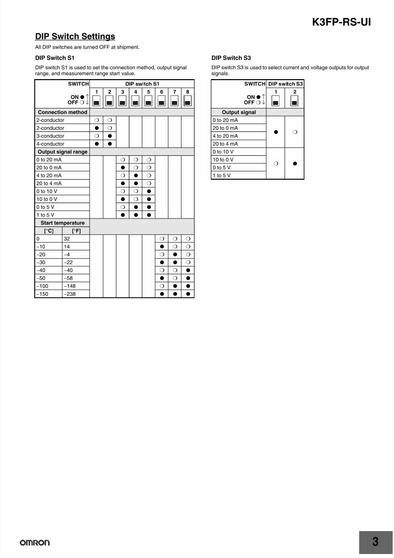
DIP Switch SettingsAll DIP switches are turned OFF at shipment.
DIP Switch S1
DIP switch S1 is used to set the connection method, output signalrange, and measurement range start value.
DIP Switch S3
DIP switch S3 is used to select current and voltage outputs for outputsignals.
SWITCH DIP switch S1
ON ↑OFF ↓
1 2 3 4 5 6 7 8
Connection method
2-conductor
2-conductor
3-conductor
4-conductor
Output signal range
0 to 20 mA
20 to 0 mA
4 to 20 mA
20 to 4 mA
0 to 10 V
10 to 0 V
0 to 5 V
1 to 5 V
Start temperature
[°C] [°F]
0 32
−10 14
−20 −4
−30 −22
−40 −40
−50 −58
−100 −148
−150 −238
SWITCH DIP switch S3
ON ↑OFF ↓
1 2
Output signal
0 to 20 mA
20 to 0 mA
4 to 20 mA
20 to 4 mA
0 to 10 V
10 to 0 V
0 to 5 V
1 to 5 V

7/29/2019 K3FP -YV-I-I
http://slidepdf.com/reader/full/k3fp-yv-i-i 28/41
K3FP-RS-UI
4
DIP Switch S2
DIP switch S2 is used to select the measurement range end value and output status for errors.
SWITCH DIP Switch S2
ON ↑OFF ↓
1 2 3 4 5 6 7 8
End temperature
[°C] [°F]0 32
5 41
10 50
15 59
20 68
25 77
30 86
35 95
40 104
45 113
50 122
55 131
60 140
65 149
70 158
75 167
80 176
85 185
90 194
95 203
100 212
110 230
120 248
130 266
140 284
150 302
160 320
170 338
180 356
190 374
200 392
210 410
Output status forerrors
A
B
C
D
SWITCH DIP Switch S2
ON ↑OFF ↓
1 2 3 4 5 6 7 8
End temperature
[°C] [°F]220 428
230 446
240 464
250 482
260 500
270 518
280 536
290 554
300 572
320 608
340 644
360 680
380 716
400 752
420 788
440 824
460 860
480 896
500 932
520 968
540 1004
560 1040
580 1076
600 1112
620 1148
640 1184
660 1220
680 1256
700 1292
750 1382
800 1472
850 1562
Output status forerrors
A
B
C
D

7/29/2019 K3FP -YV-I-I
http://slidepdf.com/reader/full/k3fp-yv-i-i 29/41
K3FP-RS-UI
5
Output Status for Errors
Relationship between Output Signal Range Selection and Output Status for Errors
Output Signal Ranges 0 to 20 mA or 20 to 0 mA
Output Signal Ranges 4 to 20 mA or 20 to 4 mA
Output Signal Ranges 0 to 10 V or 10 to 0 V
Output Signal Range 0 to 5 V
Output Signal Range 1 to 5 V
SWITCH DIP switch S2
ON ↑OFF ↓
7 8
Output statusfor errors
When disconnected onplatinum resistancethermometer side
Above measurementrange
Below measurementrange
When short-circuited onplatinum resistancethermometer side
A
Held at 5% of maximumrated output. Held at 2.5% of maximumrated output. Held at minimum ratedoutput. Held at minimum ratedoutput.
B Held at 5% of maximumrated output.
Held at 2.5% of maximumrated output.
Held at −12.5% ofminimum rated output.
Held at −25% of minimumrated output.
C Held at 5% of maximumrated output.
Held at maximum ratedoutput.
Held at minimum ratedoutput.
Held at 5% of maximumrated output.
D Held at minimum ratedoutput.
Held at maximum ratedoutput.
Held at minimum ratedoutput.
Held at minimum ratedoutput.
Output statusfor errors
DIP switch S2 When disconnected onplatinum resistancethermometer side
Above measurementrange
Below measurementrange
When short-circuited onplatinum resistancethermometer side
7 8
A 21 mA 20.5 mA 0 mA 0 mA
B 21 mA 20.5 mA 0 mA 0 mA
C 21 mA 20 mA 0 mA 21 mA
D 0 mA 20 mA 0 mA 0 mA
Output statusfor errors
DIP switch S2 When disconnected onplatinum resistancethermometer side
Above measurementrange
Below measurementrange
When short-circuited onplatinum resistancethermometer side
7 8
A 21 mA 20.5 mA 4 mA 4 mA
B 21 mA 20.5 mA 3.5 mA 3mA
C 21 mA 20 mA 4 mA 21 mA
D 4 mA 20 mA 4 mA 4 mA
Output statusfor errors
DIP switch S2 When disconnected onplatinum resistancethermometer side
Above measurementrange
Below measurementrange
When short-circuited onplatinum resistancethermometer side
7 8
A 10.5 V 10.25 V 0 V 0 V
B 10.5 V 10.25 V 0 V 0 V
C 10.5 V 10 V 0 V 10.5 V
D 0 V 10 V 0 V 0 V
Output statusfor errors
DIP switch S2 When disconnected onplatinum resistancethermometer side
Above measurementrange
Below measurementrange
When short-circuited onplatinum resistancethermometer side
7 8
A 5.25 V 5.125 V 0 V 0 V
B 5.25 V 5.125 V 0 V 0 V
C 5.25 V 5 V 0 V 5.25 V
D 0 V 5 V 0 V 0 V
Output statusfor errors
DIP switch S2 When disconnected onplatinum resistancethermometer side
Above measurementrange
Below measurementrange
When short-circuited onplatinum resistancethermometer side
7 8
A 5.25 V 5.125 V 1 V 1 V
B 5.25 V 5.125 V 0.875 V 0.75 VC 5.25 V 5 V 1 V 5.25 V
D 1 V 5 V 1 V 1 V

7/29/2019 K3FP -YV-I-I
http://slidepdf.com/reader/full/k3fp-yv-i-i 30/41
K3FP-RS-UI
6
Connections
Internal Block Diagram
Dimensions
Note: All units are in millimeters unless otherwise indicated.
4-conductor
PT100
3-conductor
PT100
2-conductor
PT100
1
2
3
4
5
6
7
8
Linking terminals
K3FP-1
−
+
Output signal
−
+
Supply voltage
Linking terminals
93.1 6.2
102.5
K3FP-RS-UI Note: 1. Use solid wire with a diameterof 2.5 mm2 max. or barterminals with insulationsleeves for terminalconnections.To preserve dielectric strengthafter connection, the length ofthe exposed conductive partinserted into the terminal must
be 12 mm max.
2. Screw Tightening TorqueRecommended torque:0.5 N·m
12 mm max. 12 mm max.
For 2.5-mm2 (max.)solid wire:
For bar terminals withinsulation sleeves:

7/29/2019 K3FP -YV-I-I
http://slidepdf.com/reader/full/k3fp-yv-i-i 31/41
K3FP-RS-UI
7
Safety PrecautionsRefer to Safety Precautions for the K3FP Series .
Precautions for Correct Use
Diagnostics Indicator
The diagnostics indicator (LED) inside the translucent cover showsthe error status, as outlined in the following table.
Connections
2-conductor Connection• For short distances (less than 10 m)
• Cable resistances RL1 and RL2 are incorporated in themeasurement result directly and falsify the result accordingly.
3-conductor Connection• For long distances between PT100 platinum resistance
thermometers and K3FP-RS-UI RTD Transducers.
• The value of all cable resistances must be exactly the same tobalance out the PT100 platinum resistance thermometer cableresistances (RL1 = RL2 = RL3).
4-conductor Connections
• For long distances between the PT100 platinum resistance
thermometer and the K3FP-RS-UI and different cable resistances(RL1 ≠ RL2 ≠ RL3 ≠ RL4).
Indicator status Error details
Flashing Measuring range span less than 50 K
Lit Disconnection on the platinum resistancethermometer side
Short circuit on the platinum resistancethermometer side
Above measurement range
Below measurement range
1
2
Inputs
3
4RL2
RL1
1
2
3
4
Inputs
RL1
RL3
RL2
1
2
3
4
Inputs
RL1
RL4
RL3
RL2
In the interest of product improvement, specifications are subject to change without notice.
ALL DIMENSIONS SHOWN ARE IN MILLIMETERS.
To convert millimeters into inches, multiply by 0.03937. To convert grams into ounces, multiply by 0.03527.
7/29/2019 K3FP -YV-I-I
http://slidepdf.com/reader/full/k3fp-yv-i-i 32/411
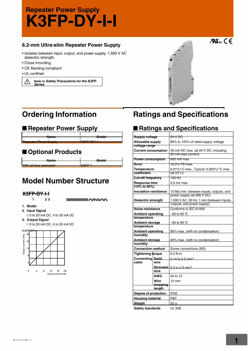
Repeater Power Supply
K3FP-DY-I-I
6.2-mm Ultra-slim Repeater Power Supply
• Isolates between input, output, and power supply. 1,500 V ACdielectric strength.
• Close mounting.
• CE Marking compliant.
• UL certified.
Refer to Safety Precautions for the K3FP Series .
Ordering Information
Repeater Power Supply
Optional Products
Model Number Structure
1. Model
2. Input Signal
I: 0 to 20 mA DC, 4 to 20 mA DC
3. Output Signal
I: 0 to 20 mA DC, 4 to 20 mA DC
Ratings and Specifications
Ratings and Specifications
Name Model
Repeater Power Supply K3FP-DY-I-I
Name Model
DIN rail bus connector K3FP-1
1 2 3
K3FP-DY-I-I
0
4
8
12
16
20
4 8 12 16 20
Input current (mA)
K3FP-DY-I-I
O u t p u t c u r r e n t ( m A )
Supply voltage 24 V DC
Allowable supplyvoltage range
80% to 125% of rated supply voltage
Current consumption 40 mA DC max. (at 24 V DC, including20 mA load current)
Power consumption 600 mA max.
Error ±0.2% FS max.
Temperaturecoefficient
0.01%/ °C max., Typical: 0.002%/ °C max.(at 23°C)
Cut-off frequency 100 Hz
Response time(10% to 90%) 3.5 ms max.
Insulation resistance 10 MΩ min. between inputs, outputs, andpower supply (at 500 V DC)
Dielectric strength 1,500 V AC, 50 Hz, 1 min (between inputs,outputs, and power supply)
Noise resistance Conforms to IEC 61000
Ambient operatingtemperature
−20 to 65°C
Ambient storagetemperature
−40 to 85°C
Ambient operatinghumidity
95% max. (with no condensation)
Ambient storagehumidity
95% max. (with no condensation)
Connection method Screw connections (M3)
Tightening torque 0.5 N·m
Connectingcable
Solidwire
0.14 to 2.5 mm2
Strandedwire
0.2 to 2.5 mm2
AWG 24 to 12
Wirestrippinglength
12 mm
Degree of protection IP20
Housing material PBT
Weight 55 g
Safety standards UL 508

7/29/2019 K3FP -YV-I-I
http://slidepdf.com/reader/full/k3fp-yv-i-i 33/41
K3FP-DY-I-I
2
Input Specifications
Output Specifications
Nomenclature
Connections
Internal Block Diagram
EMC EMI:
Radiated EMI: EN 55011
EMS:
ESD immunity: EN 61000-4-2
Rated electromagnetic field immunity:EN 61000-4-3
Burst immunity: EN 61000-4-4
Surge immunity: EN 61000-4-5
Conducted disturbance immunity:EN 61000-4-6
Input signalItem
0 to 20 mA DC, 4 to 20 mA DC
Input impedance Approx. 50 Ω
Max. input signal 50 mA
Transmitter supplyvoltage
Power supply voltage: 4.5 V max.
Transmitter supplycurrent
28 mA max.
Overcurrentdetection
Approx. 28 mA
Output signalItem
0 to 20 mA DC, 4 to 20 mA DC
Allowable loadimpedance
500 Ω max. (at I = 20 mA)
Max. output signal 28 mA
Non-load voltage 12.5 V max.
Short-circuit current ---
Ripple 20 mV pp max.
2 Transmitter power voltage
3 4 GND
7 8 Supply voltage
5 6 Output signals
Translucent cover
Snap for mounting DIN rail
DIN rail bus connection
1 Input signals
1
2
3
4GND
GND
5
6
7
8
Linking terminals
K3FP-1
−
+
−
+
Output signal
Supply voltage
Input signal +
Sensorpower output
Linking terminals

7/29/2019 K3FP -YV-I-I
http://slidepdf.com/reader/full/k3fp-yv-i-i 34/41
K3FP-DY-I-I
3
Dimensions
Note: All units are in millimeters unless otherwise indicated.
Safety Precautions
Refer to Safety Precautions for the K3FP Series .
93.1 6.2
102.5
K3FP-DY-I-INote: 1. Use solid wire with a diameter
of 2.5 mm2 max. or barterminals with insulationsleeves for terminalconnections.To preserve dielectric strength
after connection, the length ofthe exposed conductive partinserted into the terminal mustbe 12 mm max.
2. Screw Tightening TorqueRecommended torque:0.5 N·m
12 mm max. 12 mm max.
For 2.5-mm2 (max.)solid wire:
For bar terminals withinsulation sleeves:
In the interest of product improvement, specifications are subject to change without notice.
ALL DIMENSIONS SHOWN ARE IN MILLIMETERS.
To convert millimeters into inches, multiply by 0.03937. To convert grams into ounces, multiply by 0.03527.
7/29/2019 K3FP -YV-I-I
http://slidepdf.com/reader/full/k3fp-yv-i-i 35/411
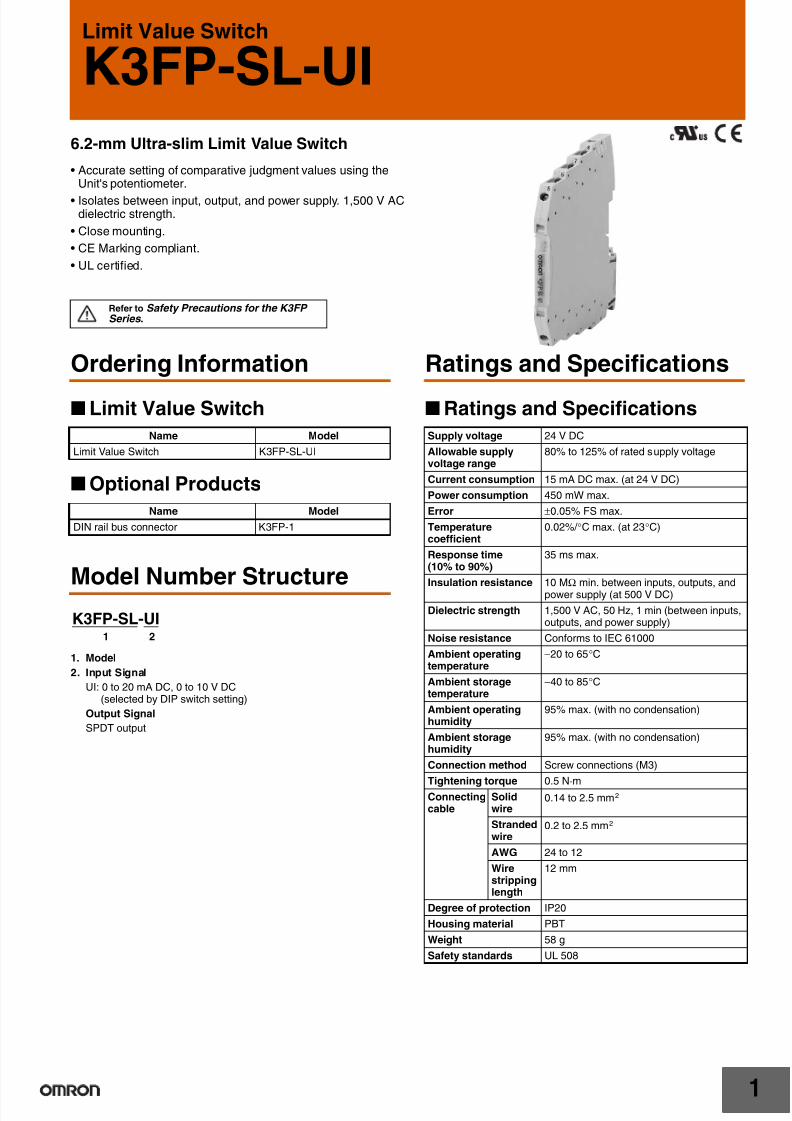
Limit Value Switch
K3FP-SL-UI
6.2-mm Ultra-slim Limit Value Switch
• Accurate setting of comparative judgment values using theUnit's potentiometer.
• Isolates between input, output, and power supply. 1,500 V ACdielectric strength.
• Close mounting.
• CE Marking compliant.
• UL certified.
Refer to Safety Precautions for the K3FP Series .
Ordering Information
Limit Value Switch
Optional Products
Model Number Structure
1. Model
2. Input Signal
UI: 0 to 20 mA DC, 0 to 10 V DC(selected by DIP switch setting)
Output Signal
SPDT output
Ratings and Specifications
Ratings and Specifications
Name Model
Limit Value Switch K3FP-SL-UI
Name Model
DIN rail bus connector K3FP-1
1 2
K3FP-SL-UI
Supply voltage 24 V DC
Allowable supplyvoltage range
80% to 125% of rated supply voltage
Current consumption 15 mA DC max. (at 24 V DC)
Power consumption 450 mW max.
Error ±0.05% FS max.
Temperaturecoefficient
0.02%/ °C max. (at 23°C)
Response time(10% to 90%)
35 ms max.
Insulation resistance 10 MΩ min. between inputs, outputs, andpower supply (at 500 V DC)
Dielectric strength 1,500 V AC, 50 Hz, 1 min (between inputs,outputs, and power supply)
Noise resistance Conforms to IEC 61000
Ambient operatingtemperature
−20 to 65°C
Ambient storagetemperature
−40 to 85°C
Ambient operatinghumidity
95% max. (with no condensation)
Ambient storagehumidity
95% max. (with no condensation)
Connection method Screw connections (M3)
Tightening torque 0.5 N·mConnectingcable
Solidwire
0.14 to 2.5 mm2
Strandedwire
0.2 to 2.5 mm2
AWG 24 to 12
Wirestrippinglength
12 mm
Degree of protection IP20
Housing material PBT
Weight 58 g
Safety standards UL 508
7/29/2019 K3FP -YV-I-I
http://slidepdf.com/reader/full/k3fp-yv-i-i 36/41
K3FP-SL-UI
2
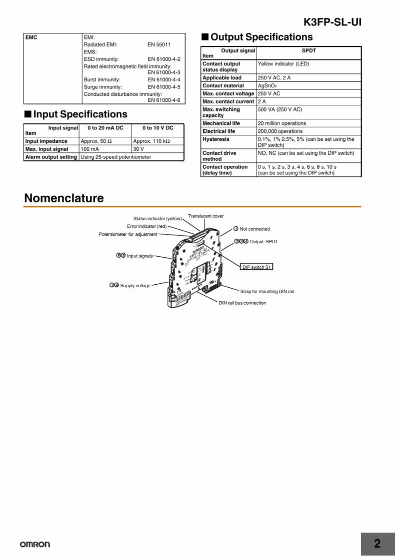
Input Specifications
Output Specifications
Nomenclature
EMC EMI:
Radiated EMI: EN 55011
EMS:
ESD immunity: EN 61000-4-2
Rated electromagnetic field immunity:EN 61000-4-3
Burst immunity: EN 61000-4-4
Surge immunity: EN 61000-4-5
Conducted disturbance immunity:EN 61000-4-6
Input signalItem
0 to 20 mA DC 0 to 10 V DC
Input impedance Approx. 50 Ω Approx. 110 kΩ
Max. input signal 100 mA 30 V
Alarm output setting Using 25-speed potentiometer
Output signalItem
SPDT
Contact outputstatus display
Yellow indicator (LED)
Applicable load 250 V AC, 2 A
Contact material AgSnO2
Max. contact voltage 250 V AC
Max. contact current 2 A
Max. switchingcapacity
500 VA (250 V AC)
Mechanical life 20 million operations
Electrical life 200,000 operations
Hysteresis 0.1%, 1% 2.5%, 5% (can be set using theDIP switch)
Contact drivemethod
NO, NC (can be set using the DIP switch)
Contact operation(delay time)
0 s, 1 s, 2 s, 3 s, 4 s, 6 s, 8 s, 10 s(can be set using the DIP switch)
1 Not connected
7 8 Supply voltage
5 6 Input signals
Translucent cover
Snap for mounting DIN rail
DIN rail bus connection
Potentiometer for adjustment
Error indicator (red)
DIP switch S1
2 3 4 Output: SPDT
Status indicator (yellow)
7/29/2019 K3FP -YV-I-I
http://slidepdf.com/reader/full/k3fp-yv-i-i 37/41

7/29/2019 K3FP -YV-I-I
http://slidepdf.com/reader/full/k3fp-yv-i-i 38/41
K3FP-SL-UI
4
Dimensions
Note: All units are in millimeters unless otherwise indicated.
93.1 6.2
102.5
K3FP-SL-UINote: 1. Use solid wire with a diameter
of 2.5 mm2 max. or barterminals with insulationsleeves for terminalconnections.To preserve dielectric strength
after connection, the length ofthe exposed conductive partinserted into the terminal mustbe 12 mm max.
2. Screw Tightening TorqueRecommended torque:0.5 N·m
12 mm max. 12 mm max.
For 2.5-mm2 (max.)solid wire:
For bar terminals withinsulation sleeves:

7/29/2019 K3FP -YV-I-I
http://slidepdf.com/reader/full/k3fp-yv-i-i 39/41
K3FP-SL-UI
5
Safety Precautions
Refer to Safety Precautions for the K3FP Series .
Precautions for Correct Use
Indicators
The status indicator (yellow LED) inside the translucent cover showswhen voltage is applied to the contact coil, i.e., that the contact isswitching.
The error indicator (red LED) inside the translucent cover shows thefollowing error status.
Setting Output Operation Values
The output operation values can be set using the potentiometer foradjustment inside the translucent cover.
Output Operation
Terminals 3 and 4 are closed and terminals 2 and 3 are open whenthe Unit power is OFF.
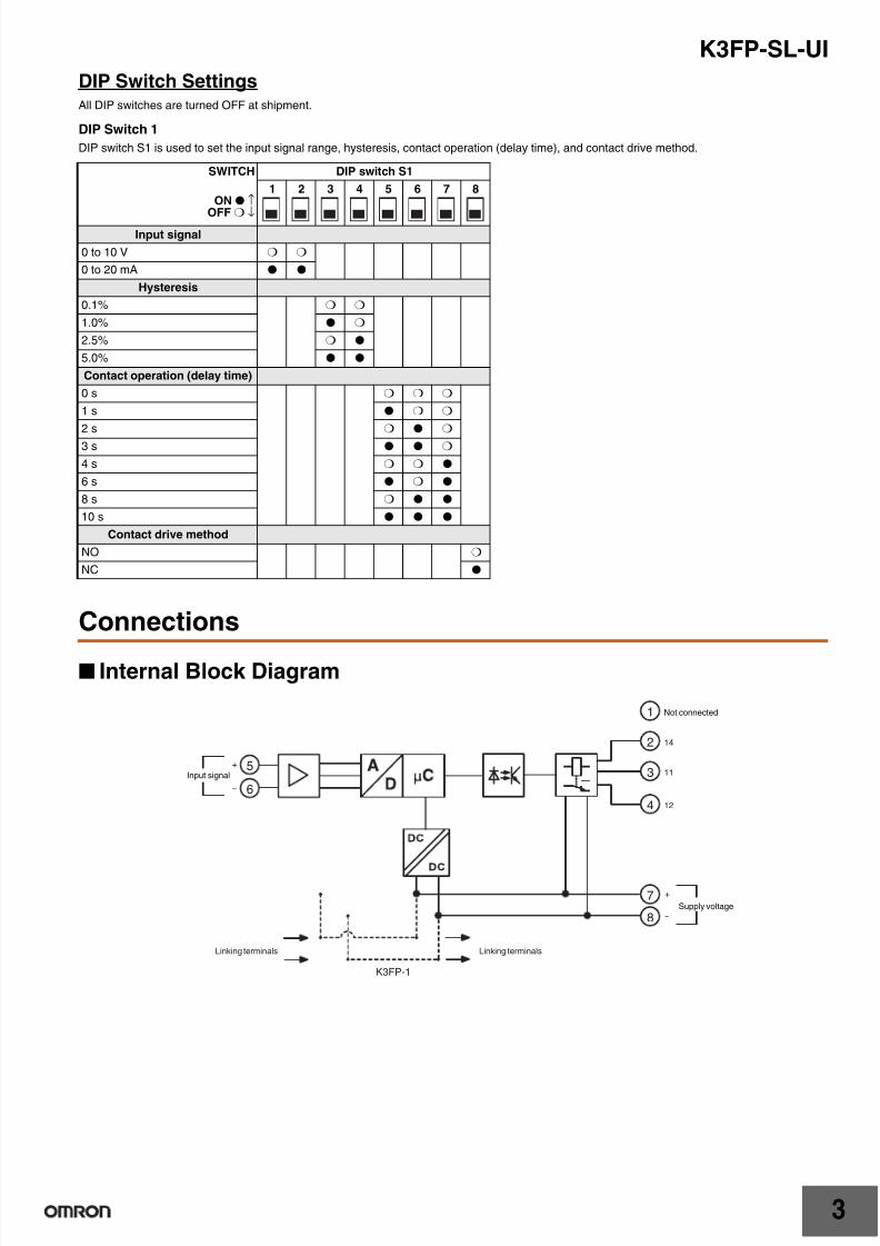
(1) Pin 8 on DIP Switch S1 Is OFF
(2) Pin 8 on DIP Switch S1 Is ON
Setting Method
1. Set the input signal, hysteresis, contact operation (delay time),and contact drive method using the DIP switch.
2. Mount the Unit to DIN rail and wire it.
3. Apply a real input signal, enter the input value (output operationvalue) for comparative judgment, and adjust using the
potentiometer.
Note: The output operation can be checked by whether the statusindicator (yellow) is lit or not lit.
Error indicatorstatus
Error details
Lit Overrange: 102.5% or more
Flashing Unit malfunction
Potentiometer for adjustment
0Input(%) 50 100
Set value
(Closed)
(Open)
(Open)
(Closed)Between terminals 3 and 4
Between terminals 2 and 3
Hysteresis
Between terminals 2 and 3
Set value
ON
OFF
0Input(%) 50 100
Set value
(Open)
(Closed)
(Closed)
(Open)Between terminals 3 and 4
Between terminals 2 and 3
Hysteresis
Between terminals 2 and 3
Set value
ON
OFF
In the interest of product improvement, specifications are subject to change without notice.
ALL DIMENSIONS SHOWN ARE IN MILLIMETERS.
To convert millimeters into inches, multiply by 0.03937. To convert grams into ounces, multiply by 0.03527.

7/29/2019 K3FP -YV-I-I
http://slidepdf.com/reader/full/k3fp-yv-i-i 40/411
Safety Precautions for the K3FP Series
Refer to Precautions in each product information sheet for specificprecautions for individual products.
!CAUTION
Precautions for Safe Use1. Do not use or store the product in the following locations.
• Locations subject to direct radiant heat from heating equipment
• Locations where the product may come into contact with water,oil, or salt water
• Locations subject to direct sunlight
• Locations where dust or corrosive gases (in particular, sulfuricor ammonia gas) are present
• Locations subject to extreme temperature changes
• Locations where icing or condensation may occur
• Locations subject to excessive shocks or vibration
• Locations subject to temperatures outside the specified range
• Locations outdoors or exposed to wind or rain
• Locations subject to static electricity or noise
2. Do not use the product in locations subject to temperaturesoutside the specified ranges or in locations subject tocondensation. If the product is installed in a panel, be sure that
the temperature around the product (not the temperature aroundthe panel) does not go outside the specified range. The life ofcomponents is dependent on the temperature. The life ofcomponents shortens when the temperature rises, and itlengthens when the temperature falls. The life of components canbe lengthened by lowering the temperature inside the product.
3. In order to prevent inductive noise, wire the lines connected to theproduct separately from power lines carrying high voltages orcurrents. Do not wire in parallel with or in the same cable aspower lines. Other measures for reducing noise include runninglines along separate ducts and using shield lines.
4. Do not install the product near devices generating strong high-frequency waves or surges. When using a noise filter, check thevoltage and current and install it as close to the product aspossible.
5. Do not use organic solvents (e.g., thinners or benzene), strong
alkaline, or strong acidic material on the outside of the product.Doing so will damage the outer cover of the product.
6. Dispose of the product as industrial waste.
Precautions for Correct Use
Wiring• Do not touch terminals or perform wiring while power is supplied to
the product. Doing so may result in injury or malfunction.
• The K3FP contains components that may be damaged ordestroyed by electrostatic discharge. When handling the K3FP,observe the necessary safety precautions against electrostaticdischarge (ESD) in accordance with EN 61340-5-1 and EN 61340-5-2 as well as IEC 61340-5-1 and IEC 61340-5-2.
• Wire to the correct terminal number. Incorrect wiring may result indamage to or burning of components.
Screw Connections
Do not touch terminals while power is supplied. Doing somay occasionally result in minor or moderate injury.
Do not allow pieces of metal, wire clippings, or finemetallic shavings or filings to enter the product. Doing somay occasionally result in minor or moderate injury or inproperty damage due to electric shock, fire, ormalfunction caused by internal short circuiting.
Do not use the product in locations where flammable orexplosive gases are present. Doing so may occasionallyresult in minor or moderate explosion, causing minor ormoderate injury, or property damage.
Tighten the screws on the terminal block and theconnector locking screws securely using therecommended tightening torque of 0.5 N·m. Loosescrews may occasionally cause fire, resulting in minor ormoderate injury, or damage to the equipment.
Product failure may occasionally prevent operation ofcomparative outputs, resulting in damage to theconnected facilities and equipment. Ensure safety in theevent of product failure by taking safety measures, suchas installing a separate monitoring system.
Do not attempt to disassemble, repair, or modify theproduct. Doing so may occasionally result in minor ormoderate injury due to electric shock.
7/29/2019 K3FP -YV-I-I
http://slidepdf.com/reader/full/k3fp-yv-i-i 41/41
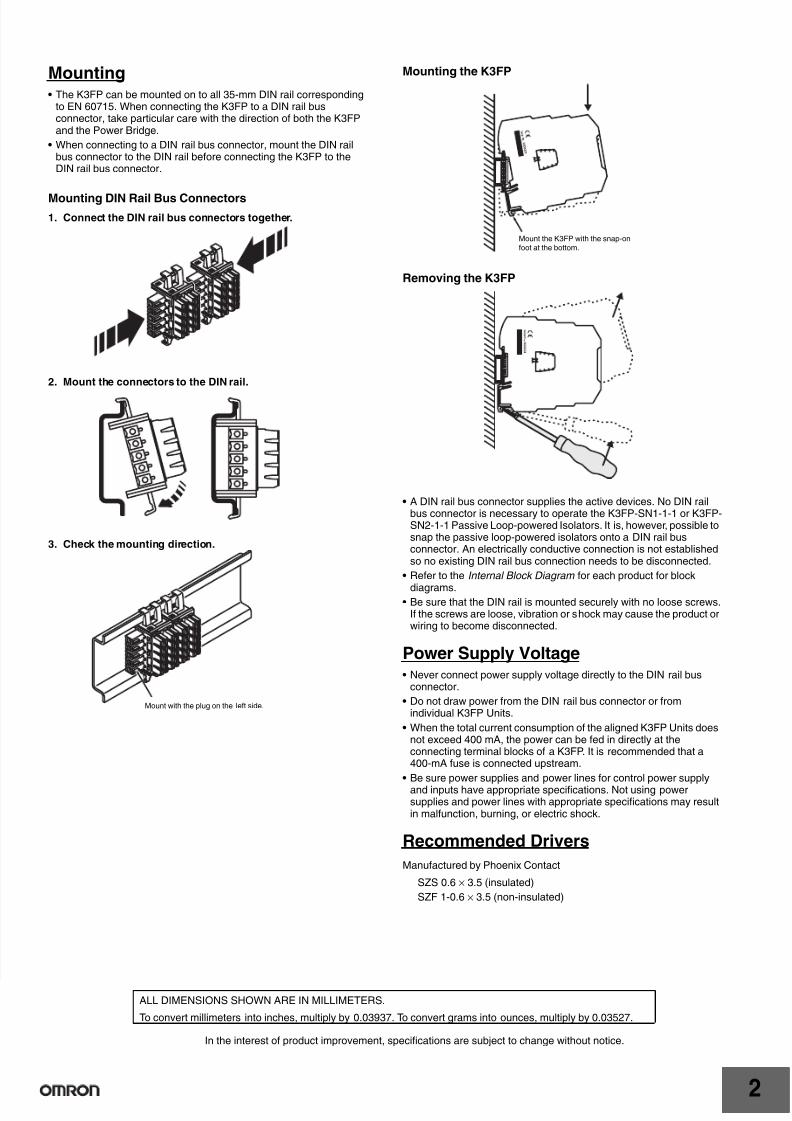
Mounting• The K3FP can be mounted on to all 35-mm DIN rail corresponding
to EN 60715. When connecting the K3FP to a DIN rail busconnector, take particular care with the direction of both the K3FPand the Power Bridge.
• When connecting to a DIN rail bus connector, mount the DIN railbus connector to the DIN rail before connecting the K3FP to theDIN rail bus connector.
Mounting DIN Rail Bus Connectors
1. Connect the DIN rail bus connectors together.
2. Mount the connectors to the DIN rail.
3. Check the mounting direction.
Mounting the K3FP
Removing the K3FP
• A DIN rail bus connector supplies the active devices. No DIN railbus connector is necessary to operate the K3FP-SN1-1-1 or K3FP-SN2-1-1 Passive Loop-powered Isolators. It is, however, possible tosnap the passive loop-powered isolators onto a DIN rail busconnector. An electrically conductive connection is not establishedso no existing DIN rail bus connection needs to be disconnected.
• Refer to the Internal Block Diagram for each product for block
diagrams.• Be sure that the DIN rail is mounted securely with no loose screws.
If the screws are loose, vibration or shock may cause the product orwiring to become disconnected.
Power Supply Voltage• Never connect power supply voltage directly to the DIN rail bus
connector.
• Do not draw power from the DIN rail bus connector or fromindividual K3FP Units.
• When the total current consumption of the aligned K3FP Units doesnot exceed 400 mA, the power can be fed in directly at theconnecting terminal blocks of a K3FP. It is recommended that a400-mA fuse is connected upstream.
• Be sure power supplies and power lines for control power supplyand inputs have appropriate specifications. Not using powersupplies and power lines with appropriate specifications may resultin malfunction, burning, or electric shock.
Recommended Drivers
Manufactured by Phoenix Contact
SZS 0.6 × 3.5 (insulated)
SZF 1-0.6 × 3.5 (non-insulated)
Mount with the plug on the left side.
Mount the K3FP with the snap-onfoot at the bottom.