circuitos de corriente directa -...
TRANSCRIPT

Circuitos de corriente directa

Corriente directa
Cuando la corriente en un circuito tiene una magnitud constante y dirección, la corriente se llama corriente directa
Debido a la que la diferencia de potencial entre las terminales de una batería es constante, la batería produce corriente directa
La batería se conoce como fuente de fem (fuerza electromotriz)

Fuerza electromotriz
La fuerza electromotriz (fem), e, de una
batería es el voltaje máximo posible que
la batería puede proporcionar entre sus
terminales
La fem proporciona energía, no es que
aplique una fuerza
La batería será normalmente la fuente
de energía del circuito

Circuito simple
Se considerara que los alambres no son elementos resistivos en un circuito
La terminal positiva de una batería está a un potencial más alto que el de la terminal negativa
Existe también una resistencia interna en la batería

Resistencia interna de una
batería
Si la resistencia interna
es cero, el voltaje entre
las terminales será
igual a la fem
En una batería real,
siempre hay una cierta
resistencia interna, r
El voltaje de las
terminales, DV = e - Ir

FEM, cont…
La fem es equivalente al voltaje de
circuito abierto
Éste es el voltaje entre las terminales
cuando no existe corriente en el circuito
Éste es el valor del voltaje que se
marca en una batería
La diferencia de potencial real entre las
terminales de la batería depende del
valor de la corriente en el circuito

Resistencia de carga
El voltaje de una terminal también es
igual al voltaje a través de la resistencia
externa
Esta resistencia exterior se llama la
resistencia de carga
En el circuito previo la resistencia de carga
es la resistencia exterior
En general, la resistencia de carga podría
ser cualquiera dispositivo eléctrico

Potencia
La potencia total de salida de una
batería es P = IDV = Ie
Esta potencia es entregada a una
resistencia exterior (I 2 R) y a una
resistencia interior (la de la batería)
P = Ie = I 2 R + I 2 r

Resistores en serie
Cuando dos o más resistores están conectados “terminal con punta”, se dice que están en serie
Para una combinacion de resistores en serie las corrientes son las mismas en todos los resistores, ya que la cantidad de carga que pasa a través de un resistor debe pasar también por los otros resistores en el mismo intervalo de tiempo.
La diferencia de potencial se divide entre los resistores, de forma tal que la suma de las diferencias de potencial a través de los resistores sea igual a la diferencia de potencial total a través de la combinación
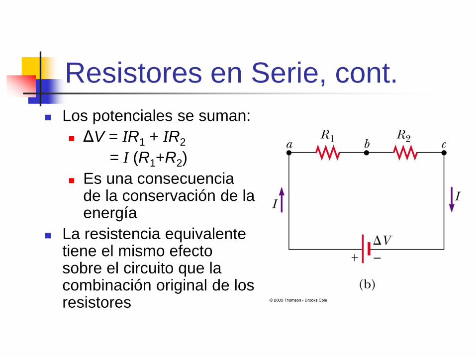
Resistores en Serie, cont.
Los potenciales se suman:
ΔV = IR1 + IR2
= I (R1+R2)
Es una consecuencia de la conservación de la energía
La resistencia equivalente tiene el mismo efecto sobre el circuito que la combinación original de los resistores
Resistencia equivalente de de
resistores en serie
Req = R1 + R2 + R3 + …
Es la suma algebraica de las resistencias individuales, y la suma siempre es mayor que cualquiera de las resistencias individuales
Si en un dispositivo resistor de un circuito en serie “se abre” se crea un circuito abierto y todos los dispositivos dejan de funcionar

Resistancia Equivalente –
Serie – Un ejemplo
Dos resistores se reemplazan por su
resistencia equivalente

Resistores en Paralelo
La diferencia de potencial a través de cada resistor
es exactamente la misma, ya que cada resistor está
directamente conectado a las terminales de la
batería
La corriente, I, que entra a un punto debe ser igual a
la suma de las corrientes que salen del mismo punto
I = I 1 + I 2
Las corrientes son generalmente distintas
Es una consecuencia de la conservación de la
carga eléctrica

Resistancia Equivalente–
caso Paralelo, Ejemplos:
La resistencia equivalente reemplaza las dos resistencias originales
Los circuitos domésticos estan alambrados de forma que losdispositivos electricos queden conectados en paralelo
Los interruptores de corriente pueden ser usados en serie con otros elementos del circuito para propósitos de seguridad.

Resistancia equivalente –caso
paralelo La resistencia equivalente
El inverso de la resistencia
equivalente de dos o más resistores conectados en paralelo es la suma algebraica de los inversos de las resistencias individuales
La resistencia equivalente es siempre menor que la menor de las resistencias en paralelo
1 2 3
1 1 1 1
eqR R R R=

Resistores en paralelo
En paralelo, cada dispositivo opera individualmente
de los otros, de tal forma que cuando uno deja de
funcionar, los demas continuan trabajando
En paralelo, todos los dispositivos operan con el
mismo valor de voltaje
La corriente circula por todos las conexiones del
circuito
El resistor de menor resistencia tendrá el valor
más alto de la corriente.
Las resietencias mas altas tendran valores de
resistencia muy pequeños, pero no nulos
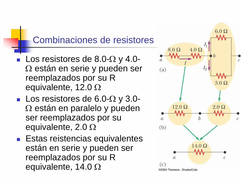
Combinaciones de resistores
Los resistores de 8.0-W y 4.0-W están en serie y pueden ser reemplazados por su R equivalente, 12.0 W
Los resistores de 6.0-W y 3.0-W están en paralelo y pueden ser reemplazados por su equivalente, 2.0 W
Estas reistencias equivalentes están en serie y pueden ser reemplazados por su R equivalente, 14.0 W
Reglas Kirchhoff’s
Hay arreglos de resistores que no
pueden ser reducidos a un circuito
simple de resistor equivalente
Se pueden usar dos reglas de
Kirchhoff, que son my útiles y que
parten de la conservación de la carga
y de la conservación de la energía

Reglas de Kirchhoff
Regla de los nudos
La suma de las corrientes que entran en un nudo
deben ser iguales a la suma de las corrientes que salen
de un nudo
Postulado de la conservación de la carga eléctrica
Regla de las mallas
La suma de las diferencias de potencial a través
de los elementos alrededor de un circuito cerrado
debe ser cero
Postulado de Conservación de la energía

Expresiones matemáticas de
las reglas de Kirchhoff
Regla de los nudos:
S Ientran = S Isalen
Reglas de las mallas:
closedloop
0VD =

La regla de los nudos
I1 = I2 + I3
De la conservación
de carga
Diagrama de un
análogo mecánico
(b)
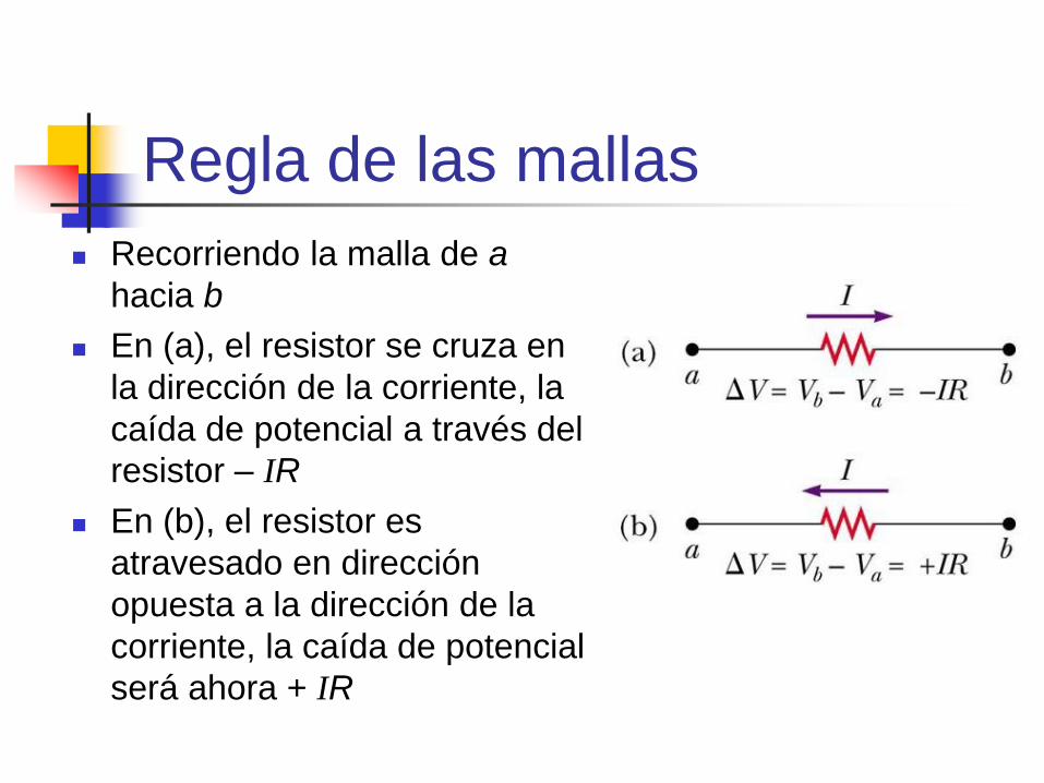
Regla de las mallas
Recorriendo la malla de a
hacia b
En (a), el resistor se cruza en
la dirección de la corriente, la
caída de potencial a través del
resistor – IR
En (b), el resistor es
atravesado en dirección
opuesta a la dirección de la
corriente, la caída de potencial
será ahora + IR
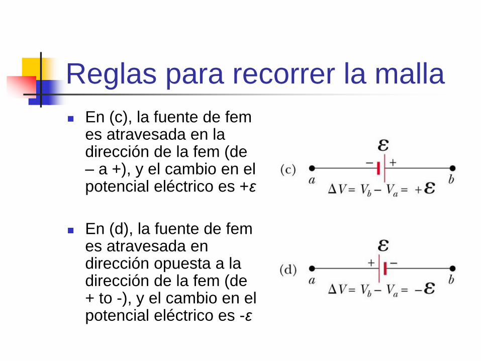
Reglas para recorrer la malla
En (c), la fuente de fem es atravesada en la dirección de la fem (de – a +), y el cambio en el potencial eléctrico es +ε
En (d), la fuente de fem es atravesada en dirección opuesta a la dirección de la fem (de + to -), y el cambio en el potencial eléctrico es -ε

Ecuaciones de nudo
Use las reglas de los nudos tantas
veces como las necesite, procurando
que en cada ecuación usted incorpore
una corriente que no haya sido usada
en una ecuación para otro nudo. El
criterio es el número de ecuaciones es
igual al número de nudos en el circuito
menos uno.
Loop Equations from
Kirchhoff’s Rules
The loop rule can be used as often as
needed so long as a new circuit element
(resistor or battery) or a new current
appears in each new equation
You need as many independent
equations as you have unknowns

Kirchhoff’s Rules Equations,
final
In order to solve a particular circuit
problem, the number of independent
equations you need to obtain from the two
rules equals the number of unknown
currents
Any capacitor acts as an open branch in a
circuit
The current in the branch containing the
capacitor is zero under steady-state conditions

Problem-Solving Hints –
Kirchhoff’s Rules
Draw the circuit diagram and assign labels
and symbols to all known and unknown
quantities. Assign directions to the currents.
The direction is arbitrary, but you must adhere to
the assigned directions when applying Kirchhoff’s
rules
Apply the junction rule to any junction in the
circuit that provides new relationships among
the various currents

Problem-Solving Hints, cont
Apply the loop rule to as many loops as are needed to solve for the unknowns
To apply the loop rule, you must correctly identify the potential difference as you cross various elements
Solve the equations simultaneously for the unknown quantities
If a current turns out to be negative, the magnitude will be correct and the direction is opposite to that which you assigned

RC Circuits
A direct current circuit may contain capacitors
and resistors, the current will vary with time
When the circuit is completed, the capacitor
starts to charge
The capacitor continues to charge until it
reaches its maximum charge (Q = Cε)
Once the capacitor is fully charged, the
current in the circuit is zero

Charging an RC Circuit
As the plates are being charged, the potential
difference across the capacitor increases
At the instant the switch is closed, the charge
on the capacitor is zero
Once the maximum charge is reached, the
current in the circuit is zero
The potential difference across the capacitor
matches that supplied by the battery
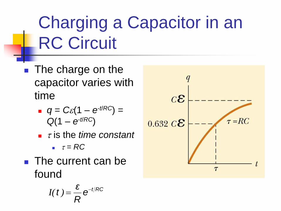
Charging a Capacitor in an
RC Circuit
The charge on the
capacitor varies with
time
q = Ce(1 – e-t/RC) =
Q(1 – e-t/RC)
t is the time constant
t = RC
The current can be
found
I( ) t RCεt e
R
=

Time Constant, Charging
The time constant represents the time
required for the charge to increase from
zero to 63.2% of its maximum
t has units of time
The energy stored in the charged
capacitor is ½ Qe = ½ Ce2
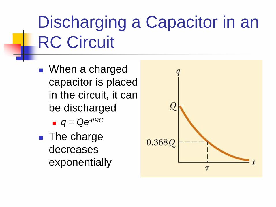
Discharging a Capacitor in an
RC Circuit
When a charged
capacitor is placed
in the circuit, it can
be discharged
q = Qe-t/RC
The charge
decreases
exponentially

Discharging Capacitor
At t = t = RC, the charge decreases to 0.368 Qmax
In other words, in one time constant, the capacitor loses 63.2% of its initial charge
The current can be found
Both charge and current decay exponentially at a rate characterized by t = RC
I t RCdq Qt e
dt RC
= =
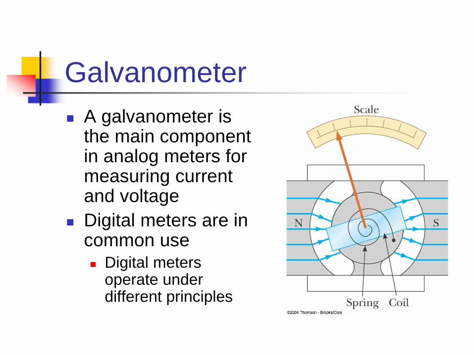
Galvanometer
A galvanometer is the main component in analog meters for measuring current and voltage
Digital meters are in common use Digital meters
operate under different principles

Galvanometer, cont
A galvanometer consists of a coil of wire
mounted so that it is free to rotate on a
pivot in a magnetic field
The field is provided by permanent
magnets
A torque acts on a current in the
presence of a magnetic field
Galvanometer, final
The torque is proportional to the current
The larger the current, the greater the torque
The greater the torque, the larger the rotation of
the coil before the spring resists enough to stop
the rotation
The deflection of a needle attached to the coil
is proportional to the current
Once calibrated, it can be used to measure
currents or voltages

Ammeter
An ammeter is a device that measures
current
The ammeter must be connected in
series with the elements being
measured
The current must pass directly through the
ammeter
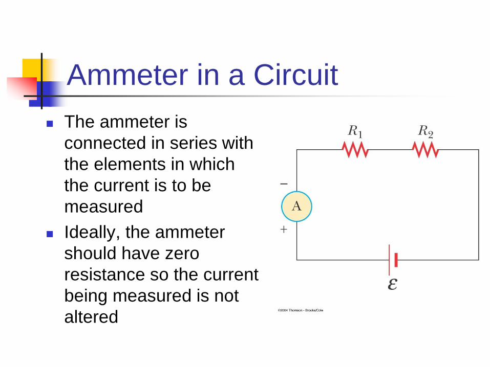
Ammeter in a Circuit
The ammeter is
connected in series with
the elements in which
the current is to be
measured
Ideally, the ammeter
should have zero
resistance so the current
being measured is not
altered
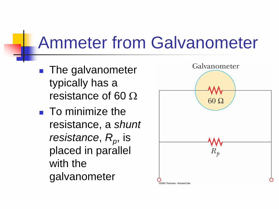
Ammeter from Galvanometer
The galvanometer
typically has a
resistance of 60 W
To minimize the
resistance, a shunt
resistance, Rp, is
placed in parallel
with the
galvanometer
Ammeter, final
The value of the shunt resistor must be
much less than the resistance of the
galvanometer
Remember, the equivalent resistance of resistors
in parallel will be less than the smallest resistance
Most of the current will go through the
shunt resistance, this is necessary since
the full scale deflection of the
galvanometer is on the order of 1 mA

Voltmeter
A voltmeter is a device that measures
potential difference
The voltmeter must be connected in
parallel with the elements being
measured
The voltage is the same in parallel
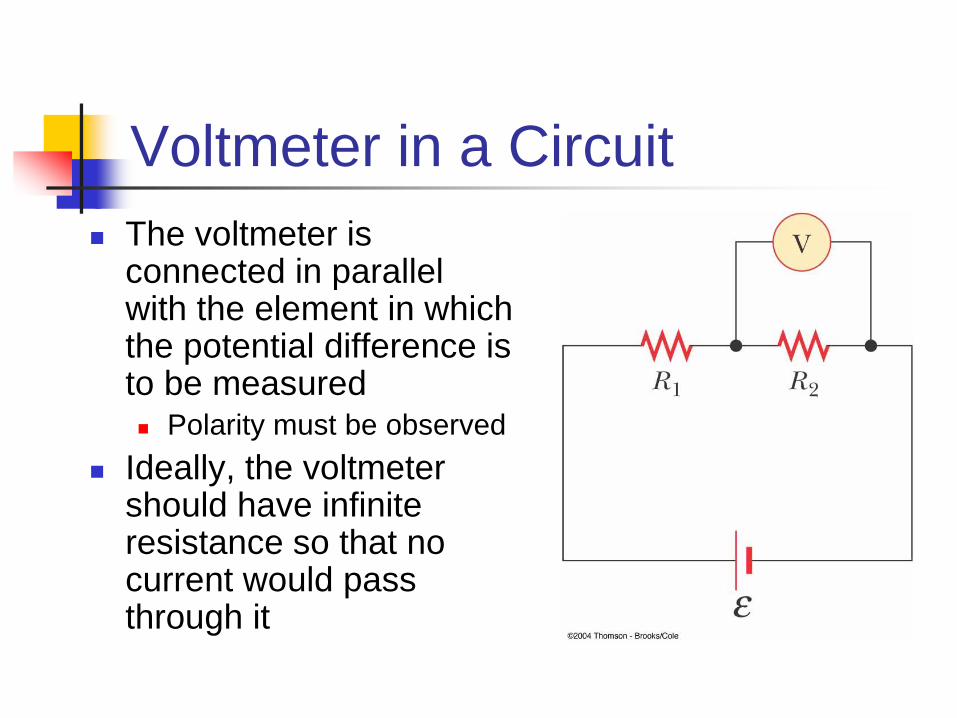
Voltmeter in a Circuit
The voltmeter is connected in parallel with the element in which the potential difference is to be measured Polarity must be observed
Ideally, the voltmeter should have infinite resistance so that no current would pass through it

Voltmeter from Galvanometer
The galvanometer
typically has a
resistance of 60 W
To maximize the
resistance, another
resistor, Rs, is
placed in series with
the galvanometer

Voltmeter, final
The value of the added resistor must be
much greater than the resistance of the
galvanometer
Remember, the equivalent resistance of resistors
in series will be greater than the largest resistance
Most of the current will go through the
element being measured, and the
galvanometer will not alter the voltage
being measured

Household Wiring
The utility company distributes electric power to individual homes by a pair of wires
Each house is connected in parallel with these wires
One wire is the “live wire” and the other wire is the neutral wire connected to ground

Household Wiring, cont
The potential of the neutral wire is taken to be zero Actually, the current
and voltage are alternating
The potential difference between the live and neutral wires is about 120 V
Household Wiring, final
A meter is connected in series with the live wire entering the house This records the household’s consumption of
electricity
After the meter, the wire splits so that multiple parallel circuits can be distributed throughout the house
Each circuit has its own circuit breaker
For those applications requiring 240 V, there is a third wire maintained at 120 V below the neutral wire
Short Circuit
A short circuit occurs when almost zero resistance exists between two points at different potentials
This results in a very large current
In a household circuit, a circuit breaker will open the circuit in the case of an accidental short circuit This prevents any damage
A person in contact with ground can be electrocuted by touching the live wire

Electrical Safety
Electric shock can result in fatal burns
Electric shock can cause the muscles of vital
organs (such as the heart) to malfunction
The degree of damage depends on:
the magnitude of the current
the length of time it acts
the part of the body touching the live wire
the part of the body in which the current exists

Effects of Various Currents
5 mA or less can cause a sensation of shock
generally little or no damage
10 mA muscles contract
may be unable to let go of a live wire
100 mA if passing through the body for 1 second or less,
can be fatal
paralyzes the respiratory muscles

More Effects
In some cases, currents of 1 A can
produce serious burns
Sometimes these can be fatal burns
No contact with live wires is considered
safe whenever the voltage is greater
than 24 V
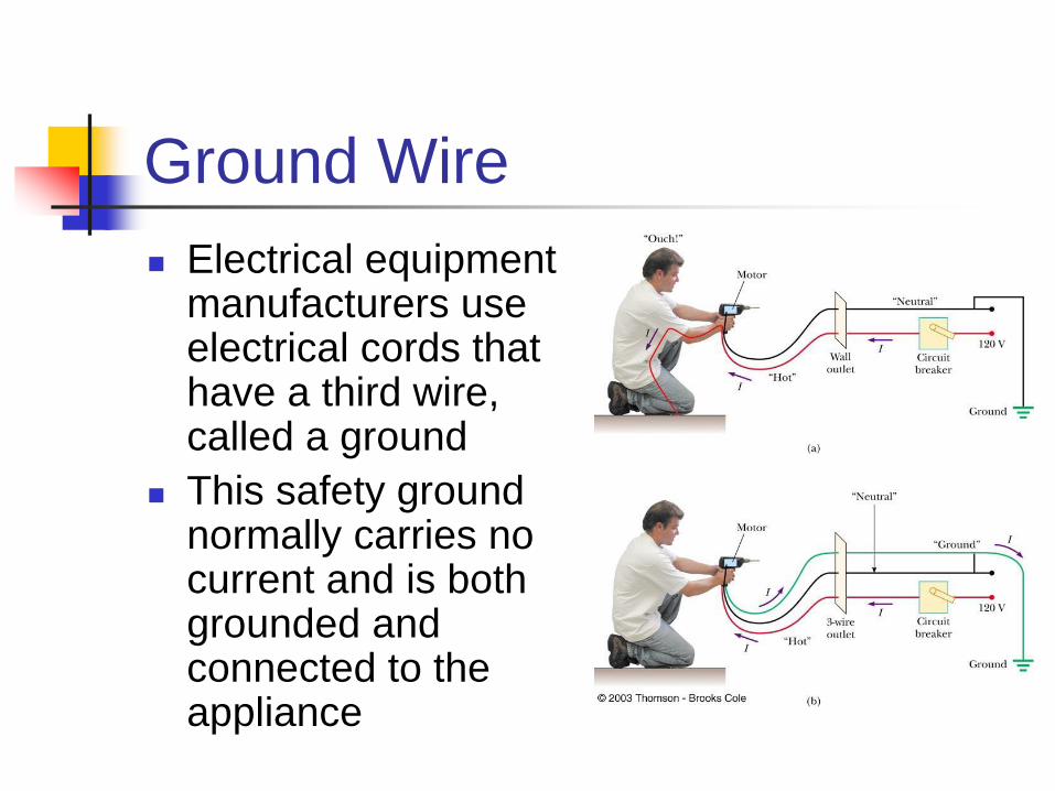
Ground Wire
Electrical equipment manufacturers use electrical cords that have a third wire, called a ground
This safety ground normally carries no current and is both grounded and connected to the appliance

Ground Wire, cont
If the live wire is accidentally shorted to
the casing, most of the current takes the
low-resistance path through the
appliance to the ground
If it was not properly grounded, anyone
in contact with the appliance could be
shocked because the body produces a
low-resistance path to ground

Ground-Fault Interrupters (GFI)
Special power outlets
Used in hazardous areas
Designed to protect people from electrical shock
Senses currents (of about 5 mA or greater) leaking to ground
Shuts off the current when above this level