c. speed transmitter and magnet … · la flecha del transmisor de rpm debe apuntar hacia la unidad...
TRANSCRIPT
A. PHYSICAL DESCRIPTIONS
C.
6 7
$
For Flat Spoke
For RoundSpoke
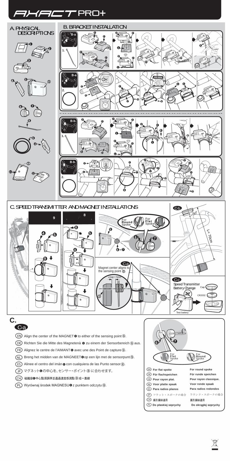
For flat spoke
Für flachspeichen
Pour rayon plat.
Voor platte spaak
Para radios planos
フラット・スポークの場合
For round spoke
Für runde speichen
Pour rayon classique.
Voor ronde spaak
Para radios redondos
ラウンド・スポークの場合
EN
DE
FR
NL
ES
JP
圓形鋼絲適用扁形鋼絲適用CH
Do płaskiej szprychy Do okrągłej szprychyPL
B. BRACKET INSTALLATIONB-a
B-b.
1
23
8
32
1
3 2
32
1
3 2
1
32
2
handlebar
3
B-a
handlebar
B-b. 2
1
2
1
13
3
2 1
2
3 2
1
3
2
2
3 2
2
1
2
2
2
2
31.
2.
1.
2.
8
C. SPEED TRANSMITTER AND MAGNET INSTALLATIONS
6 7
For Flat Spoke
For Round Spoke
Cap
CR2032
Speed Transmitter Battery Change
89
548
4
5
1. 2.
5
6 7+
C-c
9
Gap < 5mm
Magnet center aligns tothe sensing point .
C-a
S
S
Test battery
PADELMAGNET
3
6 7
9
8
10
12
4
21
5S
C-b90
L< 70cm
8
8
99
9
8
9
9
S
11
EN
DE
FR
NL
ES
JP
Align the center of the MAGNET to either of the sensing point .
Richten Sie die Mitte des Magnetenà zu einem der Sensorbereich aus.
Alignez le centre de l’AIMANT avec une des Point de capture .
Breng het midden van de MAGNEET op een lijn met de sensorpunt .
Alinee el centro del imán con cualquiera de las Punto sensor .
マグネット の中心を、センサー・ポイント に合わせます。
磁鐵座� � 中心點須調準並通過速度感測點� � � 成一直線CH
C-a
Wyrównaj środek MAGNESU z punktem odczytu .PL

L<80 cm
D. RPM TRANSMITTER AND RPM MAGNET INSTALLATION (Fig. D)
IMPORTANT: If either A) or B) is incorrect, poor signal input will result.
Cap
CR2032
RPM Transmitter Battery Change
GAP < 5 mm
PEDALMAGNET
12
8
D-3
D-4 D-5
11
Test battery
9
8
10
11
9D-1 D-2
10
11
8
s
Align the center of the MAGNET to either of the SENSING POINT. s
1. The arrow of the RPM Transmitter must point to the main unit, and install the RPM Transmitter as close to the main unit as possible and within 80cm to get a better wireless performance.(D-3)
2. Adjust the installation angle of the RPM Transmitter to aim at the direction of the main unit within +/- 15°, the best performances is at horizontal direction (0°) between the RPM Transmitter arrow and the battery cap of the main unit.
3. Make sure that the GAP between the RPM Pedal MAGNET and the RPM Transmitter is within 5mm. (D-4)4. Align the center of the RPM Pedal MAGNET to either of the sensing point .
1. Der Pfeil des DREHZAHLSENDER muss auf den Computer zeigen. Montieren Sie den DREHZAHLSENDER so nahe am Computer wie möglich, in jedem Fall jedoch im Umkreis von 80 cm, um eine gute Signalstärke zu gewährleisten. (D-3)
2. Stellen Sie den Montagewinkel des DREHZAHLSENDER so en, dass der Winkel im Verhältnis zum Computer bei +/- 15° liegt. Die besten Ergebnisse werden bei horizontaler Ausrichtung (0°) zwischen Sensorpfeil und Batteriedeckel des Computers erzielt.
3. Achten Sie darauf, dass der SPALT zwischen DREHZAHL-PEDALMAGNET und DREHZAHLSENDER im Bereich von 5 mm liegt. (D-4)4. Richten Sie die Mitte des DREHZAHL-PEDALMAGNET zu einem der Sensorbereich aus.
1. La flèche du Émetteur du compte-tours doit être dirigée vers l'unité principale ; le Émetteur du compte-tours doit être installé aussi près que possible de l'unité principale et à 80 cm (2,6 pieds) au maximum pour des performances ooptimales de la transmission sans fil. (D-3)
2. Ajutez l'angle de montage de l'émetteur du compte-tours pour le diriger vers l'unité principale +/- 15° ; les meilleures performances sont obtenues à l'horizontale (0°) entre la flèche du l'émetteur du compte-tours et le couvercle de pile de l'unité principale.
3. Vérifiez que l'espace entre l'aimant et le capteur soit inférieur à 5 mm. (D-4)4. Alignez le centre de l'aimant avec une des Point de capture .
1. La flecha del Transmisor de RPM debe apuntar hacia la unidad principal y el Transmisor de RPM ha de instalarse lo más cerca posible de la unidad principal, a un máximo de 80 cm para que el sistema inalámbrico funcione mejor.
2. Ajustar el ángulo de instalación del Transmisor de RPM para que apunte en dirección a la unidad principal con un margen de +/- 15°. El resultado es mejor en dirección horizontal (0°) entre la flecha del Transmisor de RPM y la tapa de la batería de la unidad principal.
3. Asegurarse de que el ESPACIO existente entre el imán y el Transmisor de RPM tenga como máximo 5 mm.4. Alinee el centro del imán con cualquiera de las Punto sensor .
1. De pijl van de Toerentalzender moet op de hoofdeenheid zijn gericht. Om de draadloze ontvangst te verbeteren, dient de Toerentalzender zo dicht mogelijk bij de hoofdeenheid te worden geïnstalleerd (op minder dan 80 cm). (D-3)
2. Pas de hoek van de zender zodanig aan dat deze in een hoek van +/- 15° op de hoofdeenheid staat. De beste resultaten krijgt u als de Toerentalzender horizontaal staat en er een hoek is van (0°) tussen de Toerentalzender pijl en de batterijdeksel van de hoofdeenheid.
3. Controleer of de OPENING tussen de magneet en de Toerentalzender kleiner is dan 5 mm(0.2"). (D-4)4. Breng het midden van de magneet op een lijn met de sensorpunt .
1.より良い無線性能を得るためには、RPMトランスミッター の矢印をメインユニットに向け、RPMトランスミッター ができるだけメインユニットの近く
になるよう、80cm以内の位置に取り付けてください。(D-3)2.RPMトランスミッター の取り付け角度がメインユニットに対して±15度以内になるように調整してください。RPMトランスミッター の矢印とメインユニ
ットのバッテリー・キャップが水平(0度)の状態で最高の性能が得られます。
3.RPMペダル・マグネット とRPMセンサー との距離が5mm以内になるようにしてください。 (D-4)4. マグネット の中心を、センサー・ポイント に合わせます。
�1�.無線踏板迴轉數感測發射器� � 與錶本體距離,請調整在�8�0公分之內�(無線踏板迴轉數感測發射器越靠近錶本體收到無線訊號越強�)
�2�.請將踏板迴轉數用磁鐵� � 安裝在左曲柄內測並調整好感測位置�:
�(�1�.�)踏板迴轉數用磁鐵� � � 運轉時中心線必須對準無線踏板迴轉數感測發射器� � � 的感測點
�(�2�.�)踏板迴轉數用磁鐵� � � 與無線踏板迴轉數感測距離必須小於�5毫米� �8�0公分�,超過距離可能會產生不正確訊號
1. Linia prosta wyprowadzona z Przekaźnika RPM (liczba obrotów na minutę) musi przecinać komputer umieszczony na kierownicy. Przekaźnik RPM powinien zostać zainstalowany jak najbliżej komputera, w odległości nie większej niż 80 cm, tak aby uzyskać jak największą dokładność odczytów z zestawu bezprzewodowego. (D-3)
2. Dopasuj kąt położenia Przekaźnika RPM w taki sposób, aby skierowany był w stronę umieszczonego na kierownicy komputera pod kątem +/- 15°. Najlepsze odczyty będą możliwe przy położeniu Przekaźnika RPM w płaszczyźnie horyzontalnej (0°) z przykrywką otworu na baterię w komputerze.
3. Upewnij się, że ODLEGŁOŚĆ pomiędzy MAGNESEM RPM na pedale a Przekaźnikiem RPM wynosi nie więcej niż 5 mm. (D-4)4. Wyrównaj środek MAGNESEM RPM z punktem odczytu .
EN
DE
FR
NL
ES
JP
CH
A.
B.
PL

1

2
Contents Package Contents ........................................3 Introduction ..................................................4 Using Your Computer ....................................6
1.Main Unit Setup ........................................................6 1. Programming the Main Unit 2. Basic Display Modes
2. Overview of Button Operation...............................8 1. Data Setting Mode 2. General Mode 3. Altitude Calibration Mode
3. Wheel Circumference Measurement ............... 11 4. Basic Setting & Operation .................................. 13 5. General Display .................................................... 17 6. Battery Replacement ........................................... 18 7. General Mode Display ......................................... 19 8. About Altitude Calibration .................................. 20 9. Temperature Display ........................................... 21 10. Bike 1 /Bike 2 Selection..................................... 21 11. Data Reset ........................................................... 22 12. EL Backlight........................................................ 23 13. Sleep Mode ......................................................... 23
Functions ...................................................... 24 Technical Specifications ............................. 30 General Specifications ................................ 33 Precautions................................................... 34 Trouble Shooting ......................................... 35

Package Contents 1. MAIN UNIT Main unit 3V battery (CR2032) 2. BRACKET SET Bracket for handlebar or stem Bracket base Twin adhesive tape Cable ties 3. SPEED TRANSMITTER SET Speed transmitter 3V battery (CR2032) Transmitter rubber pad Cable ties Magnet set O-ring 4. CADENCE TRANSMITTER SET
(for only) Cadence transmitter 3V battery (CR2032) Transmitter rubber pad Cable ties Magnet set O-ring 1.The installation of the accessories is on the separate sheet. 2.The accessories or parts are subject to change without prior
notice.
3

Introduction Congratulations on having chosen a cycling computer. Please read this manual carefully before using the device to get familiar with the operation logic.
The altitude calculation of this cycle computer works by measuring the atmospheric pressure. Since the weather can change, the altitude (converted from the air pressure measurement) for the same location may vary at different times. However, if there is no rapid weather change, the altitude differences caused by the weather are limited and can be generally accepted. Do not use this computer as a specialized device for altitude measurement.
The altitude value shown in each or computer is pre-calibrated by the precise
instrument at the factory before shipment. However, to get an accurate altitude measurement, we suggest that you calibrate the current altitude data before each ride. The calibration of altitude for your series is quite easy. (Refer to the content about button operation.) You may obtain the altitude information from topographic maps or the Internet. If you are unaware of your base altitude or do know your home altitude, you may reset the altitude to zero before riding. In this way, the cyclist can enjoy the fun of learning the accumulated altitude gains during a trip. Altitude data can be your reference for riding over the same hills or mountains next time.
4

There is a highly sensitive pressure sensor inside each or cycle computer,
there is a hole at the bottom of each main unit for measuring the pressure. You should always keep the hole clean to avoid incorrect measurement and must not poke a needle or any pointed article into it to avoid damage. The atmospheric pressure measured by the sensor will be converted into current altitude.
5

6
Using Your Computer 1.Main Unit Setup 1. Programming the Main Unit:
1. Before normal operation, programming the main unit and select units as stated below: 1-1. Push buttons A, B, C simultaneously for 3 seconds, and
you'll see the auto-testing display. 1-2. Press any button to quit auto-testing display, and then
select units of temperature, altitude and distance. 1-3. Press the C button to quit unit selection and enter
General Mode. 2. Situations requiring programming the main unit and select
units is as listed below: 2-1. The first time when you use the computer 2-2. When the display becomes irregular due to improper use 2-3. Whenever you change the battery
2. Basic Display Modes:
After Programming the computer, selecting units, you should enter Data Setting Mode to set basic data like wheel circumference and clock time etc. Then go to General Mode for normal operation. Before riding, you should enter Altitude Calibration Mode to calibrate the current altitude value.

The following is the General Mode Display during riding for reference:
7
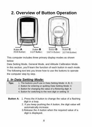
2. Overview of Button Operation
This computer includes three primary display modes as shown below: Data Setting Mode, General Mode, and Altitude Calibration Mode. In this section, you'll learn the function of each button in each mode. The following text lets you know how to use the buttons to operate the computer step by step.
1. In Data Setting Mode:Tips: 1. The buttons you'll use in Data Setting Mode: A, B, C.
2. Button for entering or quitting Data Setting Mode: C 3. Button for changing the value of a flickering digit: A 4. Button for switching to the next digit or setting: B
Button A: 1. Press the A button to change the value of a flashing
digit in a loop. 2. If you keep pushing the A button, the digit value will
automatically increase. 3.Release the A button when the required value of a
digit is displayed.
8

Button B: 1. Press the B button to move to the next digit in a loop. 2. Push the B button for 1 second to move to the next
setting. Button C: 1. In General Mode, press the C button to enter Data
Setting Mode. 2.In Data Setting Mode, press the C button to exit and
return to General Mode. Button D: No function.
How do you enter Data Setting Mode after Programming the computer? After programming the computer by pressing the A, B, C buttons at the same time for 3 seconds, press any button to quit auto-testing display, and then select units. After unit selection, press the B button for 2 seconds to enter Data Setting Mode.
2. In General Mode:Tips: 1. The buttons you'll use in General Mode: A, B, C, D 2. Button for changing the function display: A
3. Button for resetting the trip data: A (3's) 4. Button for entering Data Setting Mode: C 5. Buttons for entering Altitude Calibration Mode: A+B (3's)
Button A: 1. Press the A button to move to the next function display.
2. Press the A button for 3 seconds, and you will reset the following data: AVG SPD, MAX SPD, DST, RTM, ALT, MAX ALT, AVG RPM, MAX RPM. (AVG RPM and MAX RPM are for
only.) Button B: 1. Press the B button to turn on the EL backlight.
2. The following function is for only:
Press the B button for 1 second, and the temperature will be displayed.
Button C: Press the C button, and you'll enter Data Setting Mode.
9 Buttons A+B: Push both buttons for 3 seconds, and you'll enter

10
Altitude Calibration Mode. Button D: Press the D button to switch to Bike 1 or Bike 2.
3. In Altitude Calibration Mode:Tips:
1.The buttons you'll use in Altitude Calibration Mode: A, B. 2.Buttons for entering or quitting Altitude Calibration Mode: A+B
(3's) 3.Buttons for quickly resetting the current altitude to zero: A+B
(1's)
Buttons A+B: 1. In General Mode, push A and B buttons for 3 seconds to enter Altitude Calibration Mode.
2. In this mode, press A and B buttons at the same time briefly, and the current altitude value will return to zero. It's convenient for quick setting.
3. Push A and B buttons for 3 seconds to quit this mode and return to General Mode.
Button A: 1. Press the A button to change the plus sign to minus, or change the minus sign to plus.
2. Press the A button to change the value of a flickering digit during setting.
Button B: Press the B button to move to the next digit in a loop during setting.
About Altitude Calibration: 1. If you are aware of your home altitude or base altitude before riding, you can
directly adjust the current altitude data after you enter this mode. 2. If you do not know your base altitude before riding or if you do not
know the altitude of the starting point, you may return the current altitude value to zero in the calibration mode by pressing both A and B buttons at the same time briefly. In this way, the rider will still enjoy the fun of learning the accumulated altitude gains during each ride.

3. Wheel Circumference Measurement To set the wheel circumference before riding, you should measure the wheel circumference by yourself or refer to the Wheel Circumference Table as shown below:
11

12
How do you measure the wheel circumference yourself? Roll the wheel until the valve stem is closest to the ground and mark the corresponding spot on the floor as the first point. Next, roll the wheel forward until the valve stem is closest to the ground once again. Mark the corresponding spot on the floor as the second point. Then measure the distance between both points, using the unit of millimeter. The distance equals your wheel circumference.
1. The default value of wheel circumference for Bike 1 is 2155mm; that for Bike 2 is 2050mm. Enter the correct wheel circumference into the computer in Data Setting Mode.
2. Refer to pages 13 and 14 about basic setting to set your wheel circumference.
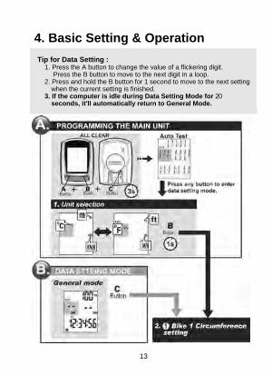
4. Basic Setting & Operation Tip for Data Setting :
1. Press the A button to change the value of a flickering digit. Press the B button to move to the next digit in a loop.
2. Press and hold the B button for 1 second to move to the next setting when the current setting is finished.
3. If the computer is idle during Data Setting Mode for 20 seconds, it'll automatically return to General Mode.
13

14

15

16
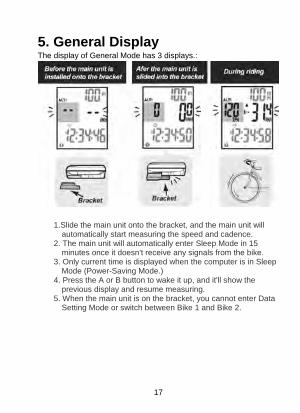
5. General Display The display of General Mode has 3 displays.:
1.Slide the main unit onto the bracket, and the main unit will
automatically start measuring the speed and cadence. 2. The main unit will automatically enter Sleep Mode in 15
minutes once it doesn't receive any signals from the bike. 3. Only current time is displayed when the computer is in Sleep
Mode (Power-Saving Mode.) 4. Press the A or B button to wake it up, and it'll show the
previous display and resume measuring. 5. When the main unit is on the bracket, you cannot enter Data
Setting Mode or switch between Bike 1 and Bike 2.
17

6. Battery Replacement
1. When the low battery indicator is shown on the display,
replace the battery. 2. The positive (+) pole of the CR2032 battery must face out.. 3.Press buttons A, B, C for 3 seconds to program the main unit. Attention: When the low battery symbol is on the screen, we suggest that you replace the battery with a new one. Otherwise, the altitude measurement result may be incorrect, and the new data may be lost.
18

7. General Mode Display When you are riding with the computer, some functions will not be displayed on the screen. These functions like Time, Altitude, ODO, mBAR, DST/D are displayed only when you stop riding.
19

8. About Altitude Calibration:
Tip for Quick Altitude Calibration
1. Press both A and B buttons for 1 second, and the current altitude value will return to zero.
2. Press the A button to set the value of a digit, and press the B button to move to the next digit.
3. Attention: Calibrate the current altitude only when there're no speed signals.
20
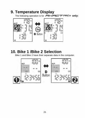
9. Temperature Display only: The following operation is for
10. Bike 1 /Bike 2 Selection Bike 1 and Bike 2 have their separate data in the computer.
21

11. Data Reset
1. Press and hold the A button for 3 seconds to reset data of DST,
RTM, MAX, AVG, ALT,MAX-ALT, MAX-RPM, AVG-RPM (for only)
2. The following data are stored in memory and cannot be reset: Unit, Cmm1 (Circumference 1), Cmm2, ODO 1, ODO 2, T.RT1, T.RT2, T.AL1, T.AL2.
3. Reset data for Bike 1 and data for Bike 2 respectively.
22

12. EL Backlight
13. Sleep Mode
Press the A or B button to wake it up.
23

Functions The display of the computer can be divided into three sections – upper, middle, and lower display. In General Mode, the LCD display of your computer is as below: The current altitude is always shown on the upper display, and it's easy to calibrate it when necessary. For users, current speed and temperature are always shown on the middle display. For users, current speed and current RPM are always shown on the middle display. Most functions are shown on the lower display-- you may press the A button to view each function display. Regarding the functions marked with listed below, the data can be reset to zero by the reset operation. (When in General Mode, press the A button for 3 seconds to reset the computer.)
ALTI Current Altitude 1. The current altitude is always displayed on the upper display. 2. To get accurate basis altitude, the cyclist should calibrate the
altitude before each ride. 3. The measurement is based on the principle that atmospheric
pressure decreases as elevation increases. 4. The altitude is measured by means of the atmospheric pressure,
so it's weather-dependent. 5. You may obtain the altitude data from a topographic map or the
Internet. 6. The altitude of the altimeter is pre-calibrated by the precise
instrument at the factory before shipment.
Current Speed 1. The current speed is always shown on the middle display during
riding. 2. The speed data are updated per second.
24

25
3. For Bike 1, when you do not ride the bike for more than 4 seconds, the speed data will be reset to zero. For Bike 2, when you do not ride the bike for more than 2 seconds, the speed data will be reset to zero.
MAX Max. Speed 1. With this function, the computer will record the maximum speed
you reach during riding. 2. Whenever you reset the computer or change the battery, the
max. speed record will be cleared. AVG Average Speed 1. With this function, the computer will display your average speed
during riding. 2. Whenever you reset the computer or change the battery, the
average speed record will be cleared. 3. It'll display "0.0" if the riding time is below 6 seconds. 4. It's updated every second on condition that the riding time is
over 6 seconds. 5. The computer will automatically reset the following data to zero
once the RTM is over 100 hours or the DST is over 1000KM (or miles): RTM (riding time), DST (trip distance), AVG (average speed.)
DST Trip Distance 1. DST refers to the accumulated distance during a trip. 2. Whenever you reset the computer or change the battery, the trip
distance record will be cleared. RTM Riding Time
1. RTM refers to the accumulated riding time of a trip. 2. Whenever you reset the computer or change the battery, the trip
distance record will be cleared. 3.The computer automatically starts measuring the riding time
upon receipt of wheel signals. If you are riding your Bike 1,

whenever you stop, the computer will continue to count the riding time for 4 more seconds to make sure there're no more wheel signals. If you are riding your Bike 2, the computer will count the riding time for 2 more seconds for the same reason. Regarding the riding time it over counts, the computer will automatically deduct it and show the correct riding time.
RPM Current Cadence (for PRO+ only) 1. RPM (Revolutions Per Minute) is a measure of rotational speed.
It's updated every second. 2. The current RPM (cadence) is always shown on the middle
display. 3. For Bike 1, if you do not turn the crank for over 4 seconds, the
current RPM will be reset to zero. For Bike 2, if you do not turn the crank for over 2 seconds, the current RPM will be reset to zero.
MAX. RPM Maximum Cadence (for PRO+ only) 1. With this function, the computer will record your maximum
cadence during riding. 2. Whenever you reset the computer or change the battery, the
max. RPM record for a trip will be cleared. *AVG RPM Average Cadence (for PRO+ only)
1. With this function, the computer will display the average cadence during riding. It's updated per second.
2. Whenever you reset the computer or change the battery, the average cadence record will be cleared.
Pace Arrow
1. The pace arrow shows the comparison between the current speed and average speed.
2. If the current speed is above or equal to the average speed, the upward arrow ( ) will flash on the display.
26
3. On the contrary, if the current speed is below the average speed, the downward arrow ( ) will flicker.

ALT Accumulated Altitude Gains (During a Trip)
1. With this function, the computer displays the accumulated altitude gains during a trip.
2. When you ride over uphill paths, the altimeter will accumulate the altitude gains. However, when you ride over downhill paths, the computer will not deduct the altitude loss. The altimeter always accumulates your altitude gains only.
3. Attention:The altitude gains are accumulated during riding only.
MAX. ALT Maximum Altitude (During a Trip)
1. With this function, the computer displays the maximum altitude you reach during a trip.
2.The max. altitude record will be cleared after you reset the computer or change the battery.
SCAN Auto-Scan
1. To start this function, press the A button for times until the scan icon is displayed.
2. When the SCAN icon is flashing, each function display in the lower screen will be shown in a loop. In the loop, each function will be displayed on the screen for 5 seconds.
3. You may disable the auto-scan function by pressing the A button again.
DST/D Distance/ Day 1. With the DST/D function, the computer accumulates the
distance of your riding in one day. 2. The DST/D data will be automatically cleared at 12:00:00 a.m.
(or 0:00:00) per day.
mBAR Millibar (Barometer) 1. The altimeter is essentially a barometer, and millibar is a unit of
atmospheric pressure. (e.g. Standard atmospheric pressure at sea level is about 1013 millibars.)
27
28
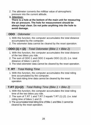
2. The altimeter converts the millibar value of atmospheric pressure into the current altitude.
3. Attention:There is a hole at the bottom of the main unit for measuring the air pressure. The hole for measurement should be always kept clean. Do not poke anything into the hole to avoid damage.
ODO Odometer 1. With this function, the computer accumulates the total distance
accumulated by the computer. 2. The odometer data cannot be cleared by the reset operation.
ODO (1) + (2) Total Odometer (Bike 1 + Bike 2) 1. With this function, the computer accumulates the total distance
of the two bikes you ride. 2. The sum of ODO 1 and ODO 2 equals ODO (1) (2). (i.e. total
distance of bikes 1 and 2) 3. The total odometer data cannot be cleared by the reset operation.
T. RT Total Riding Time
1. With this function, the computer accumulates the total riding time accumulated by the computer.
2. The total riding time data cannot be cleared by the reset operation.
T.RT (1)+(2) Total Riding Time (Bike 1 + Bike 2)
1. With this function, the computer accumulates the total riding time of the two bikes you ride.
2. The sum of T.RT 1 and T.RT 2 equals T.RT (1) (2). (i.e. total riding time of bikes 1 and 2)
3. The accumulated total riding time of Bike 1 and Bike 2 cannot be cleared by the reset operation.

T.AL Total Accumulated Altitude Gains
1. T.AL displays the total accumulated altitude gains during all previous trips .
2. The accumulated altitude gains cannot be cleared by the reset operation.
T.AL (1)+(2) Total Accumulated Altitude Gains (Bike 1 + Bike 2)
1. T.AL displays the total altitude gains accumulated during all previous trips of the two bikes you ride.
2. The sum of T.AL 1 and T.AL 2 equals T.AL (1) (2). (i.e. total accumulated altitude gains of bikes 1 and 2)
3. The accumulated altitude gains cannot be cleared by the reset operation.
A/P Clock Time: 12H/24H Alternative 1. When the user sets the clock time in Data Setting Mode, there
are two formats for option-- 12H and 24H. 2. 12H means 12 hours. In this format, A refers to AM; P refers to
PM. 24H means 24 hours. 3. When in the sleep mode, only the clock time will be displayed
on the screen.
0C/ 0F Current Temperature 1. In General Mode, the current temperature is always shown on
the middle display of . 2. If you are the user, press the B button for
1 second and you'll view the current temperature.
29

Low Battery Indicator
1. When the low-battery indicator appears on the display, it's time to replace the old battery with a new battery.
2. Replace the battery when the symbol blinks on the display. Otherwise, the new data of some functions will not be stored into the computer.
3. If you do not change the battery in a few hours, the computer may still work for a few days. The data will be displayed as usual, but the new data will not be stored before the battery is changed.
4. To save battery power, there's no EL backlight when the low-battery symbol is blinking.
LOW
Technical Specifications Symbol Function Range
Current Speed 0-199.9 km/h (0-120.0m/h)
AVG Average Speed for Bike 1 0-199.9 km/h (0-120.0m/h)
30
AVG Average Speed for Bike 2 0-199.9 km/h (0-120.0m/h)
MAX Maximum Speed for Bike 1 0-199.9 km/h (0-120.0m/h)
MAX Maximum Speed for Bike 2 0-199.9 km/h (0-120.0m/h)
Pace Arrow Compared with average speed
DST Trip Distance for Bike 1 0-999.99 km/mile
DST Trip Distance for Bike 2 0-999.99 km/mile
ODO Odometer for Bike 1 0-999999km/mile
ODO Odometer for Bike 2 0-999999km/mile
+ Total Odometer 0-1999999km/mile ODO (Bike 1 + Bike 2)

DST/D
31
Distance Per Day 0-999.99 km/mile
RTM Riding Time for Bike 1 0H:00M:00S-99H:59M:59S
RTM Riding Time for Bike 2 0H:00M:00S-99H:59M:59S
T.RT Total Riding Time for Bike 1 0H:00M:-9999H:59M
T.RT Total Riding Time for Bike 2 0H:00M:-9999H:59M
+ Total Riding Time (Bike 1 + Bike 2) 0H:00M-19999H:59M T.RT
-500m - 8000m Current Altitude (-1640ft - 26240ft) UNIT:1m/3ft
Accumulated Altitude Gains for Bike 1
0-99999m ALT (0-99999ft)
Accumulated Altitude Gains for Bike 2
0-99999m ALT (0-99999ft)
Maximum Altitude for -500m - 8000m MAX ALT Bike 1 (-1640ft - 26240ft)
Maximum Altitude for -500m - 8000m MAX ALT Bike 2 (-1640ft - 26240ft)
Total Accumulated Altitude Gains for Bike 1
0-999999m T.AL (0-999999ft)
Total Accumulated Altitude Gains for Bike 2
0-999999m T.AL (0-999999ft)
+ T.AL
Total Accumulated Altitude Gains (Bike 1+ Bike 2)
0-1999999m (0-999999ft)
Barometer 300 - 1100 mbar
Unit Selection Meter/feet, °C/°F, kilometer/mile
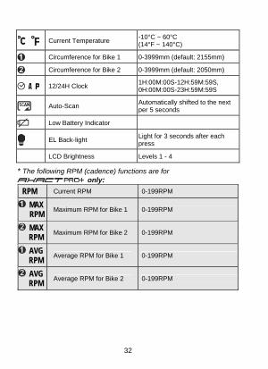
-10°C ~ 60°C
32
Current Temperature (14°F ~ 140°C)
Circumference for Bike 1 0-3999mm (default: 2155mm)
Circumference for Bike 2 0-3999mm (default: 2050mm)
1H:00M:00S-12H:59M:59S, 0H:00M:00S-23H:59M:59S 12/24H Clock
Automatically shifted to the next per 5 seconds Auto-Scan
Low Battery Indicator
Light for 3 seconds after each press EL Back-light
LCD Brightness Levels 1 - 4
* The following RPM (cadence) functions are for only:
RPM Current RPM 0-199RPM
MAX Maximum RPM for Bike 1 0-199RPM RPM
MAX RPM
Maximum RPM for Bike 2 0-199RPM
AVG Average RPM for Bike 1 0-199RPM RPM
AVG RPM
Average RPM for Bike 2 0-199RPM

33
General Specifications Operating Temperature 0°C - 50°C (32°F - 122 °F) Storage Temperature: -10°C - 60°C (14°F - 140°F) Sensor & Transmitter: No-contact magnet sensor with
wireless transmitter Suitable Fork Sizes: 12 mm - 50 mm (0.5" - 2.0") Battery Operating Life: CR2032 in Main Unit About one year (based on the
average riding time of 1.5 hours per day)
CR2032 in Speed Transmitter Around 24000 km (15000 miles) CR2032 in RPM Transmitter Around 600 hours Dimensions & Weight (Main Unit): 44.4 x 62.6 x 19.1 mm, 37.15 g
The specifications and design are subject to change without prior notice.

34
Precautions 1. Watch the road. Do not focus attention on your cycle computer
functions during riding to avoid accidents. 2. Don't expose the main unit to direct sunlight for a long time while
you're not riding with it. 3. Never disassemble the device or the accessories. 4. Don't poke a needle or any pointed article into the hole on the
bottom of the main unit. To poke anything into the hole may damage the pressure sensor inside the device.
5. Check the positions of the sensor and magnet, and check the gap between both parts regularly. Make sure they are always in normal condition.
6. Use a dry or slightly damp cloth to clean the computer when necessary. Do not use thinner, alcohol or benzine to clean the product.
7. Do not operate the computer under water though it's waterproof. Note there are sensitive components inside the main unit.
8. Be alert to sudden weather change during long-distance riding to avoid danger. And sudden change in temperature may cause a temporary incorrect altitude display.
35
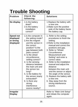
Trouble Shooting Problem Check the
following: Solutions
No display
1.Is the battery dead?
2.Is the battery installation correct?
1.Replace the battery with a new one.
2.Make sure the positive pole of the battery faces the battery cap.
Speed not displayed or wrong displayed
1.Is the computer in the setting mode?
2.Are the magnet and the sensor in the correct position? Is the gap between both parts correct?
3. Is the wheel circumference setting correct?
4. Is the sensing distance between the main unit and the sensor too long?
5. Is the battery for the sensor nearly exhausted?
6. Is there any strong interference source nearby?
1. Refer to the setting procedures to finish the setting.
2.Refer to the installation manual and correct the positions and gap.
3. Refer to "Wheel Circumference Measurement and Setting" and enter a correct value.
4. Refer to the installation manual and adjust the distance between the main unit and the sensor or adjust the angle of the sensor.
5. Replace the battery with a new one.
6. Stay away from the strong interference source.
Irregular Display
Refer to "Main Unit Setup" and initiate the computer again.

36
LCD is black.
Did you expose the main unit to the direct sunlight for a long time when it was not in use?
Put the main unit in the shade to let it return to normal state.
Display is slow.
Is the temperature below 00C (320F)?
The computer will return to normal state when the temperature rises.
Low-battery symbol is blinking.
Replace the battery in the main unit with a new one.
Altitude not displayed or wrong displayed
1. Did you calibrate the altitude before riding?
2.Is the hole for measuring the air pressure on the bottom of the main unit clean?
1.Refer to "Overview of Button Operation" and calibrate the altitude before each ride.
2.Always keep the hole for measuring the air pressure clean. Do not poke anything into the hole to avoid damage.
www.giant-bicycles.com