tutorial parte 2 usos avanzados de la netfpga...
TRANSCRIPT

Tutorial Parte 2Usos avanzados de la NetFPGA
Presentado por:Luis Santamaria, Jhon Padilla
Universidad Pontificia Bolivariana
http://NetFPGA.org
Tutorial NetFPGASeptiembre 5-7 2010
Requerimientos de Buffer en el RouterPor qué el tamaño del Buffer importa?
Ya que se tienen múltiples puertos en un Router enviando datos, se necesitan buffers. Se requieren buffers o colas pequeñas para reducir el retardo Y buffer grandes para la gran cantidad de paquetes que
puedan llegar. El problema es que son costosos.
Lo que se quiere hacer es reducir la memoria usando routers y switches: Uso de Teoría de Colas
Por la misma naturaleza del tráfico no hay una respuesta correcta de que tan grande o pequeño tiene que ser un Buffer.
Tutorial NetFPGA Septiembre 5-7 2010
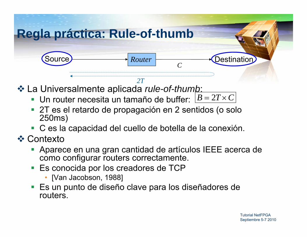
La Universalmente aplicada rule-of-thumb: Un router necesita un tamaño de buffer: 2T es el retardo de propagación en 2 sentidos (o solo
250ms) C es la capacidad del cuello de botella de la conexión.
Contexto Aparece en una gran cantidad de artículos IEEE acerca de
como configurar routers correctamente. Es conocida por los creadores de TCP
• [Van Jacobson, 1988] Es un punto de diseño clave para los diseñadores de
routers.
Regla práctica: Rule-of-thumb
CTB 2
CRouterSource Destination
2T

Tutorial NetFPGA Septiembre 5-7 2010
Explorando los tamaños del Buffer
Para ver los efectos de cambiar el tamaño del buffer en un flujo TCP se debe ajustar el tamaño de la memoria de una cola de salida en el hardware real.
Se necesita reducir el tamaño del buffer y medirlo en tiempo real.
No es posible en Routers comercialesPor eso usamos NetFPGA
Objetivo: Usar la NetFPGA para entender que tan grande se
necesita un buffer para un flujo TCP unico.

Rule for adjusting W– If an ACK is received: W ← W+1/W– If a packet is lost: W ← W/2
Tutorial NetFPGA Septiembre 5-7 2010
Porque 2TxC para un único flujo TCP?
Only W packets may be outstanding
http://guido.appenzeller.net/anims/

Time evolution of a single TCP flow through a router. Buffer is < 2T*C
Tutorial NetFPGA Septiembre 5-7 2010
Time Evolution of a Single TCP FlowTime evolution of a single TCP flow through a router. Buffer is 2T*C
Enhanced Router
Objectives Observe router with new modules New modules: rate limiting, event capture
Execution Run event capture router Look at routing tables Explore details pane Start tcp transfer, look at queue occupancy Change rate, look at queue occupancy
Tutorial NetFPGA Septiembre 5-7 2010

Tutorial NetFPGA Septiembre 5-7 2010
Step 1 - Run Pre-made Enhanced Router
Start terminal and cd to “netfpga/projects/tutorial_router/sw/”
Type “./tut_adv_router_gui.pl”
A familiar GUI should start
Tutorial NetFPGA Septiembre 5-7 2010
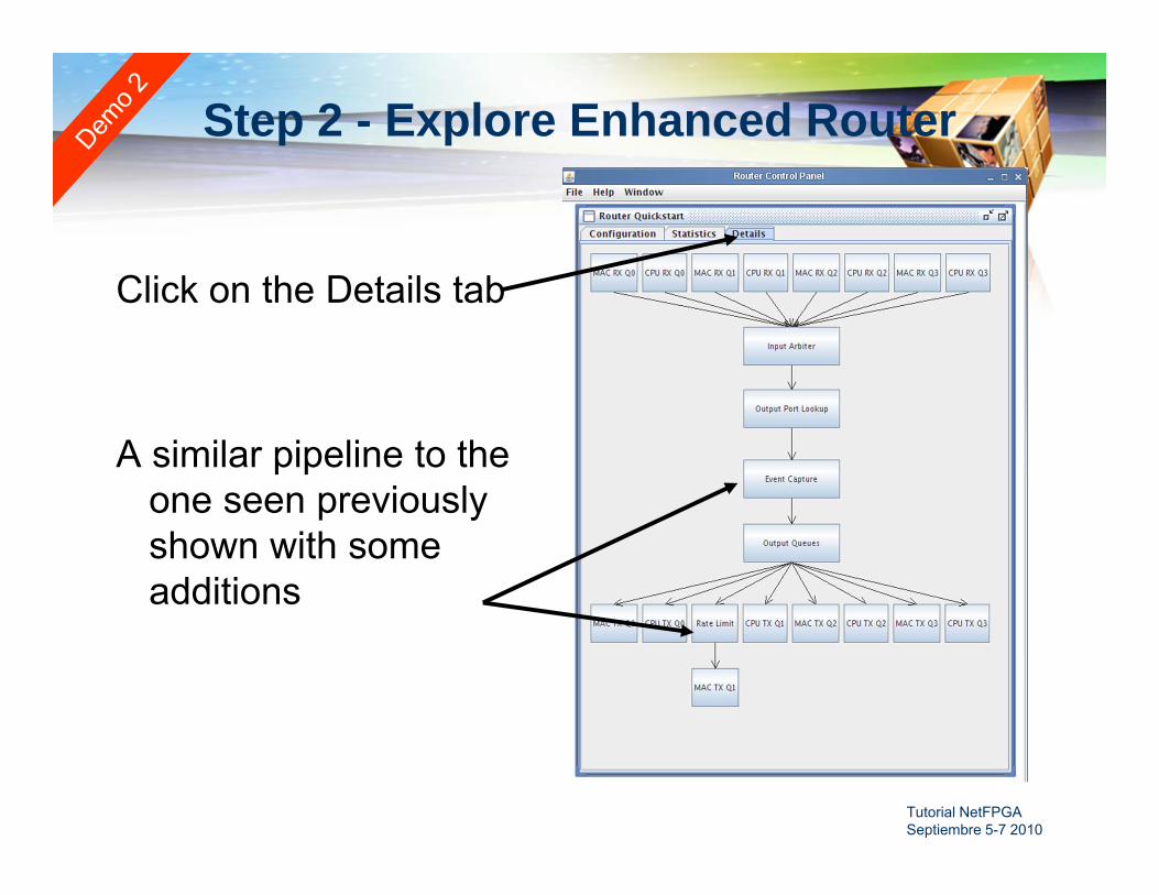
Step 2 - Explore Enhanced Router
Click on the Details tab
A similar pipeline to the one seen previously shown with some additions

Tutorial NetFPGA Septiembre 5-7 2010
Enhanced Router Pipeline
Two modules added1. Event Capture to
capture output queue events (writes, reads, drops)
2. Rate Limiterto create abottleneck
MACRxQ
CPURxQ
MACRxQ
CPURxQ
MACRxQ
CPURxQ
MACRxQ
CPURxQ
Input Arbiter
Output Port Lookup
MACTxQ
CPUTxQ
MACTxQ
CPUTxQ
MACTxQ
CPUTxQ
MACTxQ
CPUTxQ
pOutput Queues
RateLimiter
Event Capture

Tutorial NetFPGA Septiembre 5-7 2010
Step 3 - Decrease the Link RateTo create bottleneck and show
the TCP “sawtooth,” link-rate is decreased.
In the Details tab, click the “Rate Limit” module
Check Enabled
Set link rate to 1.953Mbps
Tutorial NetFPGA Septiembre 5-7 2010
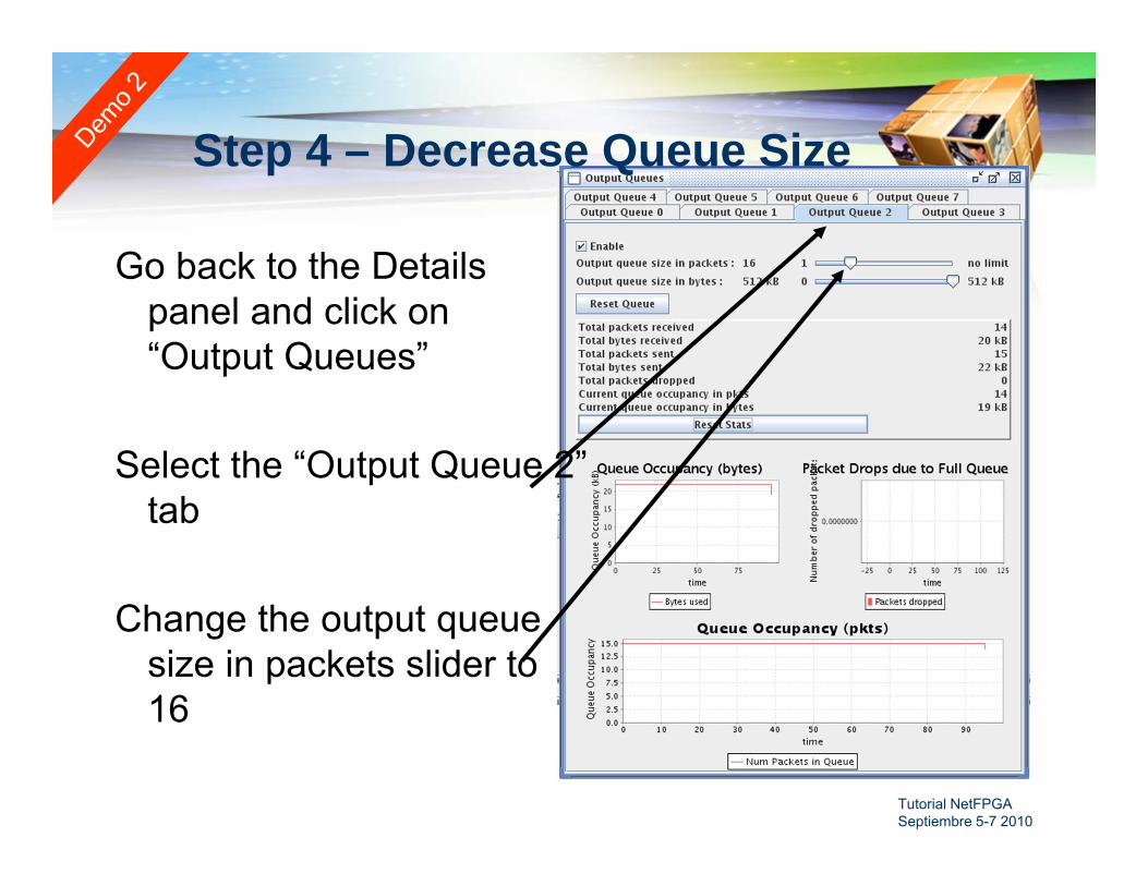
Step 4 – Decrease Queue Size
Go back to the Details panel and click on “Output Queues”
Select the “Output Queue 2” tab
Change the output queue size in packets slider to 16

Tutorial NetFPGA Septiembre 5-7 2010
Step 5 - Start Event Capture
Click on the Event Capture module under the Details tab
This should start the configuration page

Tutorial NetFPGA Septiembre 5-7 2010
Step 6 - Configure Event Capture
Check Send to local hostto receive events on the local host
Check Monitor Queue 2 to monitor output queue of MAC port1
Check Enable Captureto start event capture

Tutorial NetFPGA Septiembre 5-7 2010
Step 7 - Start TCP Transfer
We will use iperf to run a large TCP transfer and look at queue evolution
Start a terminal and cd to“netfpga/projects/tutorial_router/sw”
Type “./iperf.sh”
Tutorial NetFPGA Septiembre 5-7 2010
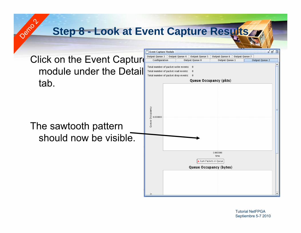
Step 8 - Look at Event Capture Results
Click on the Event Capture module under the Details tab.
The sawtooth pattern should now be visible.
Tutorial NetFPGA Septiembre 5-7 2010
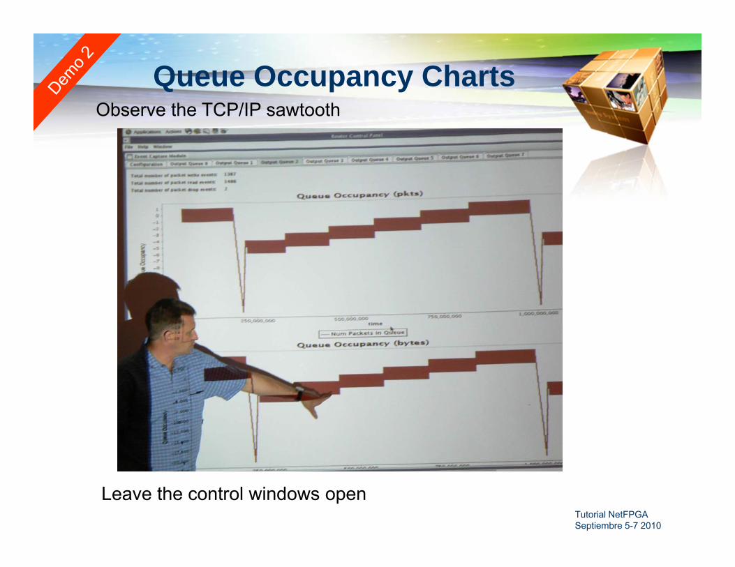
Queue Occupancy Charts
Leave the control windows open
Observe the TCP/IP sawtooth
Paquete NetFPGA
Utilidades Simulation Synthesis Registers
Librerias Verilog (módulos compartidos)
Proyectos (reference and contributed)
Tutorial NetFPGA Septiembre 5-7 2010

Simulación y Síntesis
Simulation (nf_run_test.pl) Permite simular desde la línea de comandos o desde
la interfaz GUI Existe la forma de crear paquetes, generar registros
read y write para la simulación (Perl and Python)
Synthesis (make) Se hace make en el directorio synth del proyecto Sirve para hacer la compilación en software Automáticamente se incluyen componentes Xilinx
Coregen de las librerías compartidas Includes all Xilinx Coregen components form a
projects synth directory (.xco)
Tutorial NetFPGA Septiembre 5-7 2010
Librerías Compartidas de Verilog(modulos)
Localizadas en la carpeta netfpga/lib/verilog
Se especifican las librerías en el archivo project.xml Cualquier proyecto puede usar cualquier
modulo
Los Módulos locales en un directorio src sobre-escriben una librería compartida. Si arp_reply es encontrado tanto en la librería
compartida como en src, solo se usa el de src
Tutorial NetFPGA Septiembre 5-7 2010

Sistema de Registros
Project XML (project.xml) Se encuentra en el directorio project/include Especifica las librerías compartidas y la ubicación de los registros
en pipeline
Cada modulo con registros tiene un archivo XML Especifica el nombre de los registros y sus tamaños (por defecto
son de 32bits, si se especificara uno de 64 el automáticamente crea 2 registros)
Los archivos de registro se crean automáticamente usando el comandonf_register_gen.pl Perl header files C header files Verilog file defining registers
Tutorial NetFPGA Septiembre 5-7 2010

Proyectos de referencia
Se pueden extender y agregar nuevos módulosfácilmente
Algunos ejemplos: Reference NIC Reference Router Reference Switch Router KIT (SW que corre encima del Rrouter) Router Buffer Sizing
Lo que se hace usualmente es utilizar un proyecto agregarle un modulo nuevo.(NIC, Router y Switch son lo mismo excepto por el modulo outport lookup)
Tutorial NetFPGA Septiembre 5-7 2010
Tutorial NetFPGA Septiembre 5-7 2010
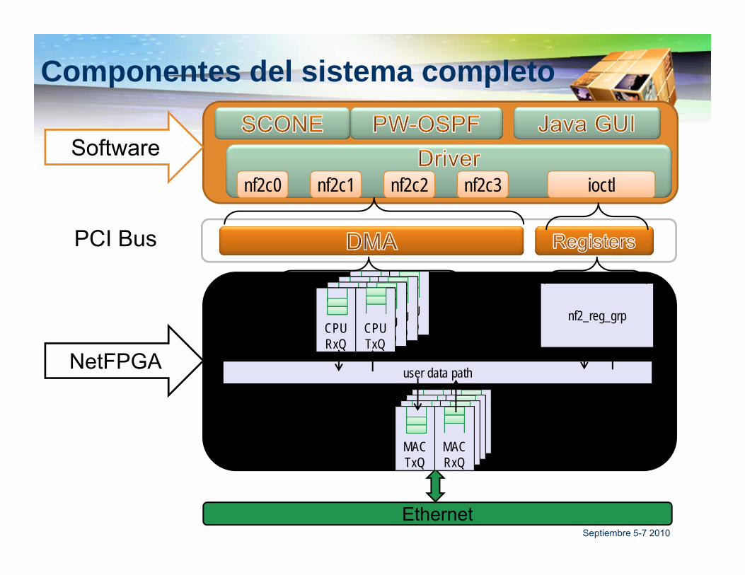
Componentes del sistema completo
Software
PCI Bus
NetFPGA
CPURxQ
CPUTxQ
nf2_reg_grp
user data path
nf2c0 nf2c1 nf2c2 nf2c3 ioctl
MACTxQ
MACRxQ
Ethernet
CPURxQ
CPUTxQ
CPURxQ
CPUTxQ
CPURxQ
CPUTxQ
MACTxQ
MACRxQ
MACTxQ
MACRxQ
MACTxQ
MACRxQ

Tutorial NetFPGA Septiembre 5-7 2010
Reference Router Pipeline Cinco etapas
Input buffers: Un MAC para cada puerto físico y un CPU para un puerto lógico.
Input arbiter: atiende las colas de entrada y envía los paquetes al siguiente módulo
Output Port Lookup: Decisión de enrutamiento y modificación del paquete
Output queuing Output buffers
Interfaz de módulos basada en los paquetes
Diseñado para fácil interconexión
MACRxQ
CPURxQ
MACRxQ
CPURxQ
MACRxQ
CPURxQ
MACRxQ
CPURxQ
Input Arbiter
Output Port Lookup
MACTxQ
CPUTxQ
MACTxQ
CPUTxQ
MACTxQ
CPUTxQ
MACTxQ
CPUTxQ
Output Queues

port0 port2192.168.2.y192.168.1.x
Tutorial NetFPGA Septiembre 5-7 2010
Vida del paquete dentro del Hardware

Tutorial NetFPGA Septiembre 5-7 2010
Comunicación entre módulos
Usando “Module Headers” que se le colocan a cadapaquete que pasa por la NetFPGA:
IP HdrEth Hdr
…00
0Last word of packet0x10
Last Module Hdry
……
Module HdrxContiene información como longitud del paquete, puerto de entrada puerto de salida,…
Data Word(64 bits)
Ctrl Word(8 bits)

Visión general del Procesamiento interno de los paquetes

data
Tutorial NetFPGA Septiembre 5-7 2010
Comunicación entre módulos
ctrl
wr
rdy
Data (64bits) Crtl Word (8bits)La señal Wr indica que el modulo previo le esta intentando escribir al modulo siguiente.Rdy indica que el modulo siguiente esta listo para recibir datos.
Tutorial NetFPGA Septiembre 5-7 2010
MAC Rx Queue

Tutorial NetFPGA Septiembre 5-7 2010
Rx Queue
IP Hdr:IP Dst: 192.168.2.3, TTL:
64, Csum:0x3ab4
Eth Hdr:Dst MAC = port 0,
Ethertype = IP
Data
0
0
0
Pkt length,input port = 00xff
Tutorial NetFPGA Septiembre 5-7 2010
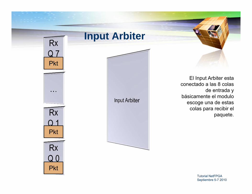
Input Arbiter
Pkt
Pkt
Pkt
El Input Arbiter esta conectado a las 8 colas
de entrada y básicamente el modulo
escoge una de estas colas para recibir el
paquete.

Tutorial NetFPGA Septiembre 5-7 2010
Output Port Lookup
Asi funciona el Output Port Lookup en el Reference Router

IP Hdr:IP Dst: 192.168.2.3, TTL:
64, Csum:0x3ab4
IP Hdr:IP Dst: 192.168.2.3, TTL:
63, Csum:0x3ac2
Tutorial NetFPGA Septiembre 5-7 2010
Output Port Lookup
EthHdr: Dst MAC = 0Src MAC = x,Ethertype = IP
Data
0
0
0
Pkt length,input port = 00xff
1- Check input port matches
Dst MAC
2- Check TTL, checksum
3- Lookup next hop IP & output
port (LPM)
4- Lookup next hop MAC
address (ARP)
5- Add output port header
6- Modify MAC Dst and Src addresses
7-Decrement TTL and update
checksum
EthHdr: Dst MAC = nextHopSrc MAC = port 4,
Ethertype = IP
Pkt length,input port = 0
output port = 4
Asi funciona el Output Port Lookup en el Reference Router
Tutorial NetFPGA Septiembre 5-7 2010
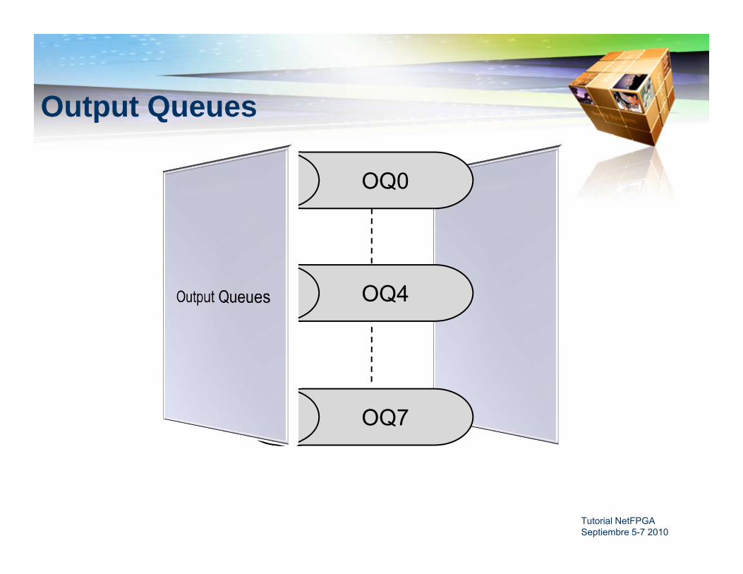
Output Queues
OQ0
OQ4
OQ7

Tutorial NetFPGA Septiembre 5-7 2010
MAC Tx Queue
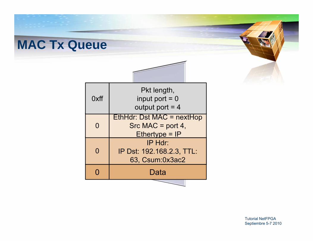
Tutorial NetFPGA Septiembre 5-7 2010
MAC Tx Queue
IP Hdr:IP Dst: 192.168.2.3, TTL:
64, Csum:0x3ab4
IP Hdr:IP Dst: 192.168.2.3, TTL:
63, Csum:0x3ac2
EthHdr: Dst MAC = nextHopSrc MAC = port 4,
Ethertype = IP
Data
0
0
0
Pkt length,input port = 0
output port = 40xff

Tutorial NetFPGA Septiembre 5-7 2010
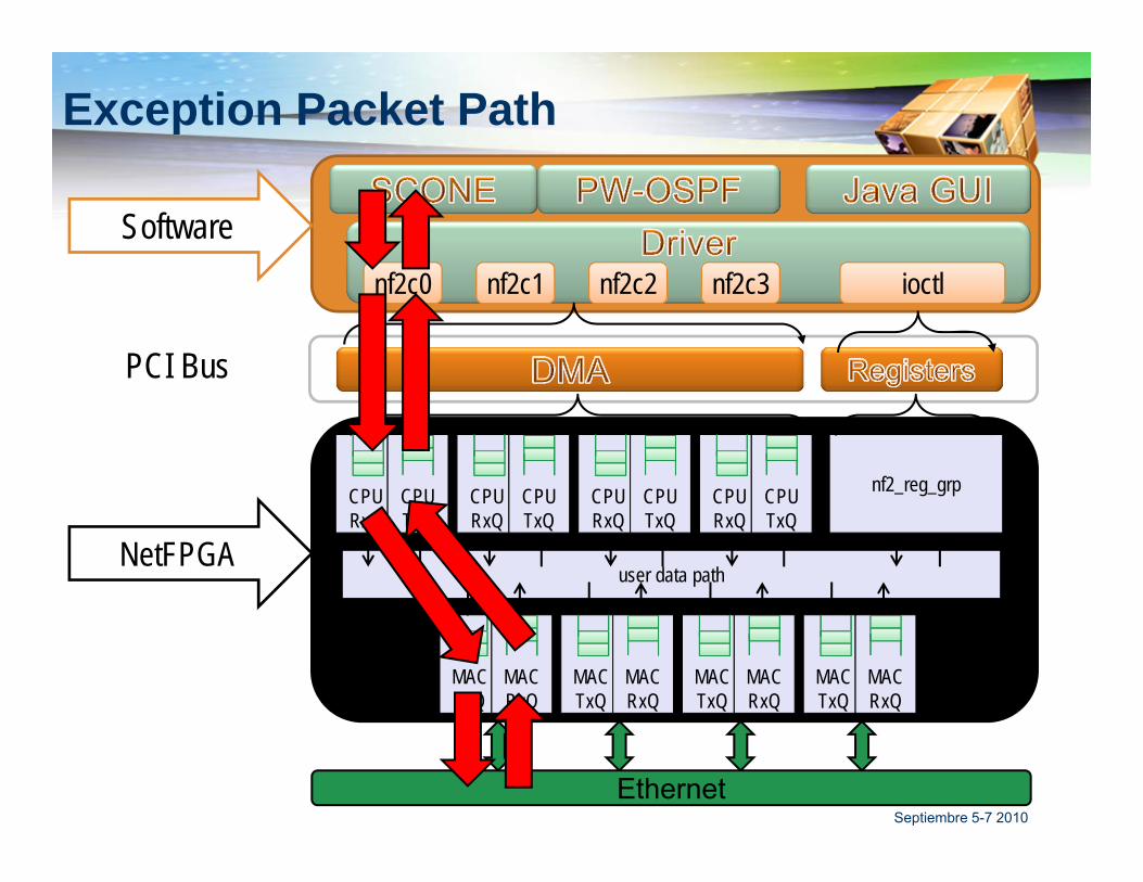
Exception Packet
Ejemplo: TTL = 0 or TTL = 1El paquete tiene que ser enviado a la CPU la cual
va a generar un paquete ICMP de respuesta En la etapa de Output Port Lookup hay unas
diferencias
Tutorial NetFPGA Septiembre 5-7 2010
Exception Packet Path
Software
PCI Bus
NetFPGA
CPURxQ
CPUTxQ
CPURxQ
CPUTxQ
CPURxQ
CPUTxQ
CPURxQ
CPUTxQ
nf2_reg_grp
user data path
nf2c0 nf2c1 nf2c2 nf2c3 ioctl
MACTxQ
MACRxQ
MACTxQ
MACRxQ
MACTxQ
MACRxQ
MACTxQ
MACRxQ
Ethernet
IP Hdr:IP Dst: 192.168.2.3, TTL:
1, Csum:0x3ab4
Tutorial NetFPGA Septiembre 5-7 2010
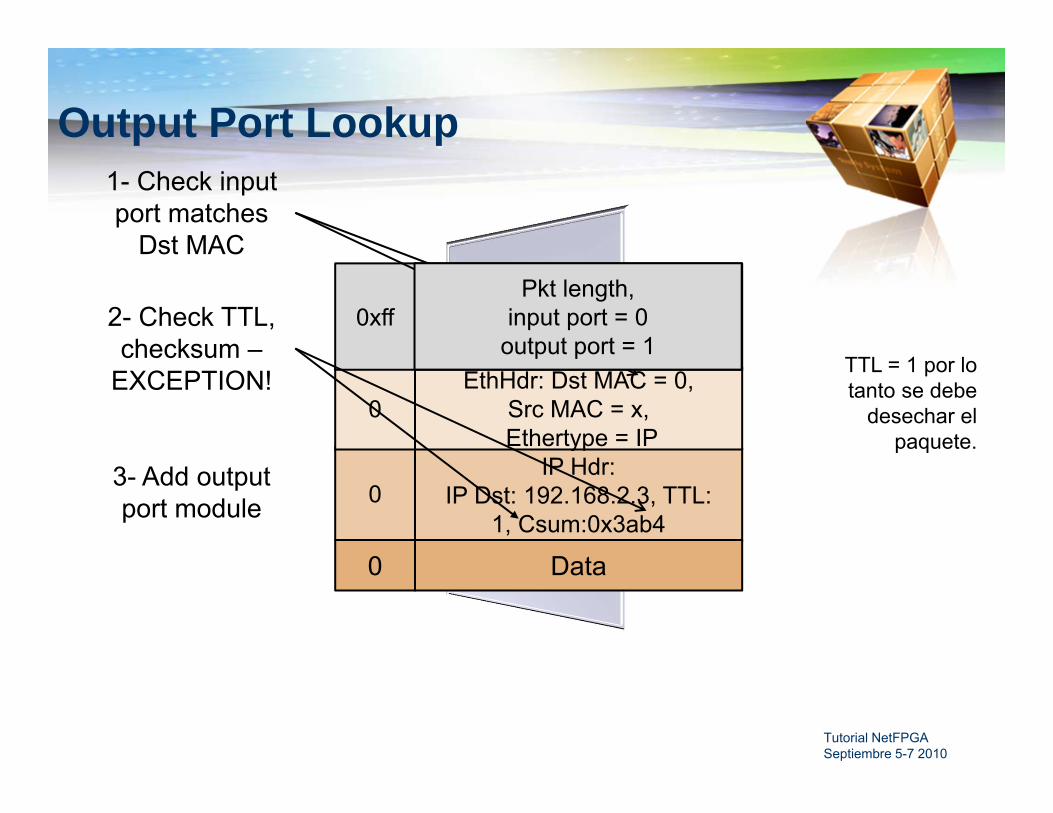
Output Port Lookup
EthHdr: Dst MAC = 0,Src MAC = x,Ethertype = IP
Data
0
0
0
Pkt length,input port = 00xff
1- Check input port matches
Dst MAC
2- Check TTL, checksum –
EXCEPTION!
3- Add output port module
Pkt length,input port = 0
output port = 1TTL = 1 por lo tanto se debe
desechar el paquete.

Tutorial NetFPGA Septiembre 5-7 2010
Output Queues
OQ0
OQ1
OQ2
OQ7

Tutorial NetFPGA Septiembre 5-7 2010
CPU Tx Queue

Tutorial NetFPGA Septiembre 5-7 2010
CPU Tx Queue
IP Hdr:IP Dst: 192.168.2.3, TTL:
1, Csum:0x3ab4
EthHdr: Dst MAC = 0, Src MAC = x,Ethertype = IP
Data
0
0
0
Pkt length,input port = 0
output port = 10xff

Tutorial NetFPGA Septiembre 5-7 2010
ICMP PacketPara el paquete ICMP, el paquete llega a la cola
Rx CPU desde el Bus PCI.Sigue el mismo camino que un paquete desde la
MAC hasta que llega al Output Port LookupEl modulo OPL ve que el paquete viene del CPU
Rx Cola 1 y setea el puerto de salida directamente a 0.
El paquete luego continua el mismo camino que un paquete non-exception hacia el Output Queues y luego al MAC Tx Cola 0

Tutorial NetFPGA Septiembre 5-7 2010
ICMP Packet Path
Software
PCI Bus
NetFPGA
CPURxQ
CPUTxQ
CPURxQ
CPUTxQ
CPURxQ
CPUTxQ
CPURxQ
CPUTxQ
nf2_reg_grp
user data path
nf2c0 nf2c1 nf2c2 nf2c3 ioctl
MACTxQ
MACRxQ
MACTxQ
MACRxQ
MACTxQ
MACRxQ
MACTxQ
MACRxQ
Ethernet
Tutorial NetFPGA Septiembre 5-7 2010
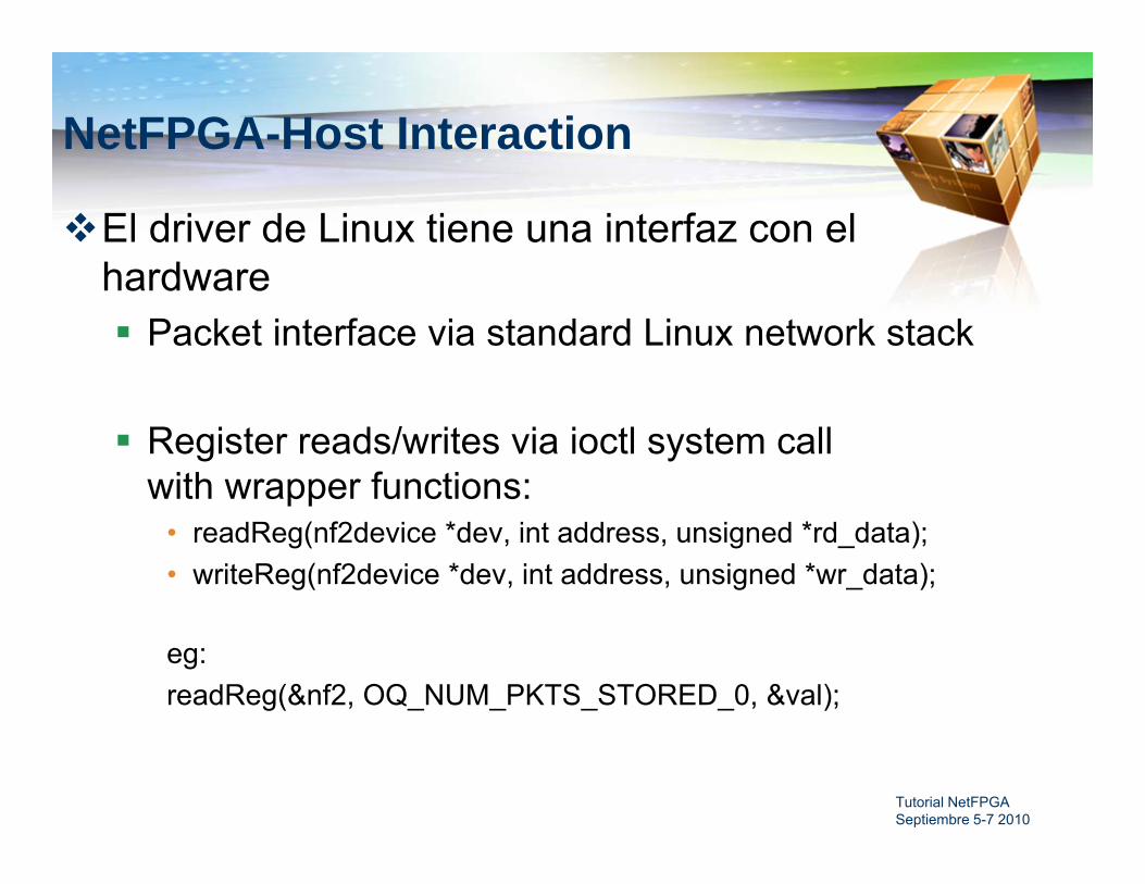
NetFPGA-Host Interaction
El driver de Linux tiene una interfaz con el hardware Packet interface via standard Linux network stack
Register reads/writes via ioctl system call with wrapper functions:
• readReg(nf2device *dev, int address, unsigned *rd_data);• writeReg(nf2device *dev, int address, unsigned *wr_data);
eg:readReg(&nf2, OQ_NUM_PKTS_STORED_0, &val);
Tutorial NetFPGA Septiembre 5-7 2010
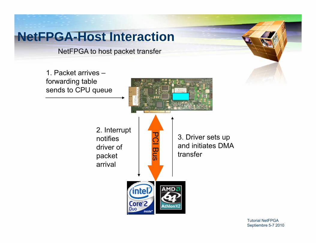
NetFPGA-Host InteractionNetFPGA to host packet transfer
PC
I Bus
2. Interrupt notifies driver of packet arrival
3. Driver sets up and initiates DMA transfer
1. Packet arrives –forwarding table sends to CPU queue

Tutorial NetFPGA Septiembre 5-7 2010
NetFPGA-Host InteractionNetFPGA to host packet transfer (cont.)
PC
I Bus
4. NetFPGA transfers packet via DMA
5. Interrupt signals completion of DMA
6. Driver passes packet to network stack

Tutorial NetFPGA Septiembre 5-7 2010
NetFPGA-Host InteractionHost to NetFPGA packet transfers
PC
I Bus
3. Interrupt signals completion of DMA
1. Software sends packet via network sockets
Packet delivered to driver
2. Driver sets up and initiates DMA transfer

Tutorial NetFPGA Septiembre 5-7 2010
NetFPGA-Host InteractionRegister access
PC
I Bus
1. Software makes ioctl call on network socket
ioctl passed to driver
2. Driver performs PCI memory read/write

Tutorial NetFPGA Septiembre 5-7 2010
NetFPGA-Host Interaction
Packet transfers shown using DMA interface
Alternative: use programmed IO to transfer packets via register reads/writes slower but eliminates the need to deal with network
sockets

Tutorial NetFPGA Septiembre 5-7 2010
Drop 1 in N Packets
Objectives Add counter and FSM to the code Synthesize and test router
Execution Open drop_nth_packet.v Insert counter code Synthesize After synthesis, test the new system.

Tutorial NetFPGA Septiembre 5-7 2010
New Reference Router Pipeline
One module added1. Drop Nth Packet to
drop every Nth packet from the reference router pipeline
MACRxQ
CPURxQ
MACRxQ
CPURxQ
MACRxQ
CPURxQ
MACRxQ
CPURxQ
Input Arbiter
Output Port Lookup
MACTxQ
CPUTxQ
MACTxQ
CPUTxQ
MACTxQ
CPUTxQ
MACTxQ
CPUTxQ
pOutput Queues
RateLimiter
Event Capture
Drop Nth Packet
Tutorial NetFPGA Septiembre 5-7 2010
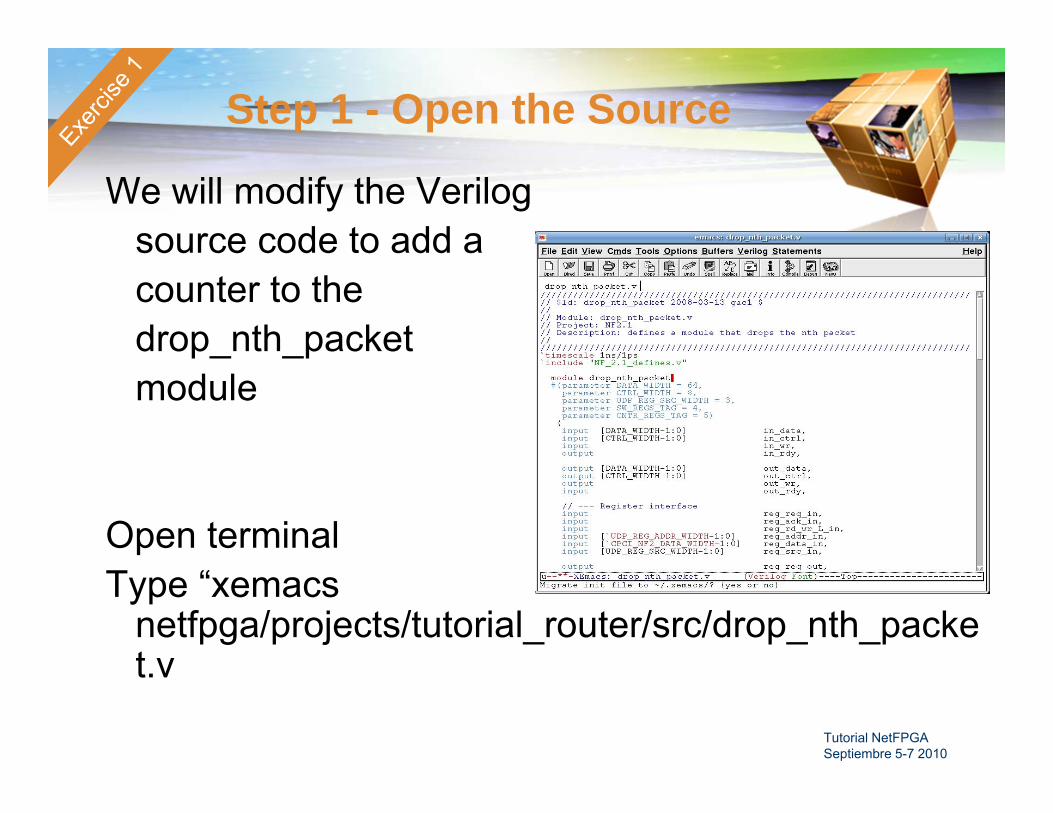
Step 1 - Open the Source
We will modify the Verilogsource code to add acounter to the drop_nth_packet module
Open terminalType “xemacs
netfpga/projects/tutorial_router/src/drop_nth_packet.v

Tutorial NetFPGA Septiembre 5-7 2010
Step 2 - Add Counter to Module
Add counter using the following signals:• counter
–16 bit output signal that you should increment on each packet pulse
• rst_counter– reset signal (a pulse input)
• inc_counter– increment (a pulse input)
Search for insert counter (ctrl+s insert counter, Enter)
Insert counter and save(ctrl+x+s)
Tutorial NetFPGA Septiembre 5-7 2010
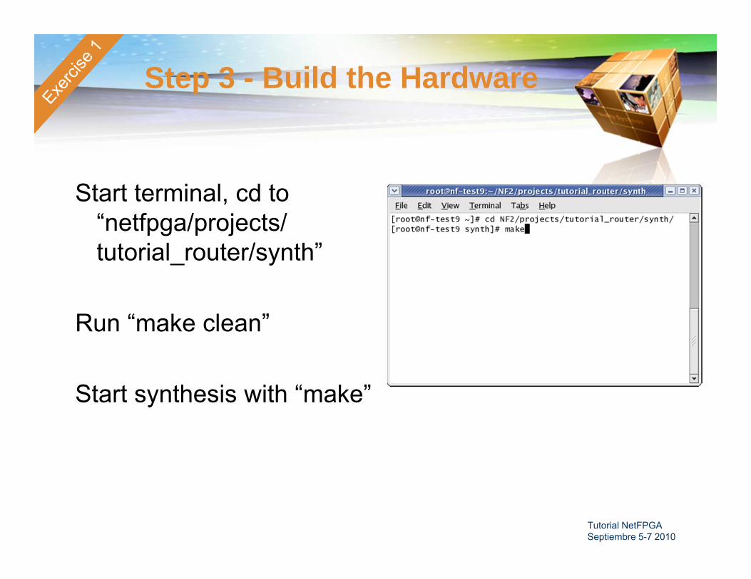
Step 3 - Build the Hardware
Start terminal, cd to “netfpga/projects/tutorial_router/synth”
Run “make clean”
Start synthesis with “make”

Tutorial NetFPGA Septiembre 5-7 2010
Step 5 – Test your RouterYou can watch the number of received and sent packets to watch the
module drop every Nth packet. Ping a local machine (i.e. 192.168.7.1) and watch for missing pings
To run your router:1- Enter the directory by typing:
cd netfpga/projects/tutorial_router/sw2- Run the router by typing:
./tut_adv_router_gui.pl --use_bin ../../../bitfiles/tutorial_router.bit
To set the value of N (which packet to drop)type regwrite 0x2000704 N– replace N with a number (such as 100)
To enable packet dropping, type: To disable packet dropping, type:regwrite 0x2000700 0x1 regwrite 0x2000700 0x0

Tutorial NetFPGA Septiembre 5-7 2010
Step 5 – Measurements Determine iperf TCP throughput to neighbor’s server
for each of several values of N Similar to Demo 2, Step 8
• cd netfpga/projects/tutorial_router/sw• ./iperf.sh
Ping 192.168.x.2 (where x is your neighbor’s server) TCP throughput with:
• Drop circuit disabled– TCP Throughput = ________ Mbps
• Drop one in N = 1,000 packets– TCP Throughput = ________ Mbps
• Drop one in N = 100 packets– TCP Throughput = ________ Mbps
• Drop one in N = 10 packets– TCP Throughput = ________ Mbps
Explain why TCPs throughput is so low given that only a tiny fraction of packets are lost