traducción del manual original - avdel global · conjunto de caja de cambios 17 conjunto motor 18...
TRANSCRIPT

Manua l de I ns t rucc ionesTraducc ión de l manua l o r ig i na l
Máquina Neumát ica de Inser tos Roscados
74110


3
Í nd ice
Normas de Seguridad 4
Especificaciones de la máquina 5Dimensiones de la máquina 5
Uso previstoSelección de la máquina 6 & 7
Puesta en servicioSuministro de aire 8Procedimiento de funcionamiento 8Ajuste del embrague 9Accesorios 9
BoquillasInstrucciones de colocación 10Instrucciones de servicio 10Componentes de la boquilla 11 & 12
Mantenimiento de la máquinaMantenimiento diario 13Mantenimiento semanal 13
Datos de seguridad (Grasa) 14
MantenimientoReinicialización del Par de Embrague 15Conjunto de Embrague 16Conjunto de caja de cambios 17Conjunto Motor 18Ajuste de la varilla empujadora 19
Montaje general de la máquina base 20, 22
Lista de componentes 21,23
Diagnóstico de averías 24 & 25
La política de AvdelUK Ltd es la del desarr ollo y mejora continua del producto, r eservándose el derecho de cambiar las especi fi caciones de cualquier pr oducto sin previo aviso.
GarantíaLas máquinas de colocación de Avdel poseen una garantía de 12 meses frente adefectos originados por componentes defectuosos o por mano de obra, iniciándoseel período de garantía a par entrega confirmada por la factura o nota de envio.La garantía es aplicable al usuario / comprador cuando la venta se realice a travésde un distribuidor autorizado, y únicamente con el propósito adecuado. La garantíaquedará invalidada si no se lleva a cabo el servicio, el mantenimiento y elfuncionamiento de la máquina de instalación de acuerdo a las instruccionescontenidas en los Manuales de servicio e instrucciones. En caso de fallo o defecto,queda a la elección de Avdel el llevar a cabo la reparación o la sustituci ón de loscomponentes defectuosos.

4
Normas de Segur idad
1 No la usen para otro propósito que no sea aquel para el que está diseñada.
2 Para esta máquina no usen otro equipo que el recomendado y suministrado por Avdel .
3 Cualquier modificación realizada por el cliente en la máquina, las boquillas, accesorios o en cualquier equipo suministrado por
Avde l o por sus representantes, será de entera responsabilidad del cliente. Avdel aconsejar á gustosamente sobre cualquier
modificación propuesta.
4 La máquina debe mantenerse en condiciones seguras de trabajo en todo momento y debe ser examinada a intervalos regulares
en cuanto a funcionalidad y existencia de posibles daños por personal con formación adecuada. Cualquier operación de
desmontaje será únicamente llevada a cabo por personal con conocimiento en los procedimientos de Avdel . No desmontar esta
máquina / herramienta sin consultar previamente las instrucciones de mantenimiento. Sirvanse contactar con Avdel haciendo
mención a sus necesidades de formación.
5 La máquina debe funcionar, en todo momento, de acuerdo con la legislación vigente en Seguridad y Salud. Cualquier pregunta
referente a la utilización correcta de la máquina y a la seguridad del operario, deberá estar dirigida a Avdel.
6 Las precauciones que deben observarse cuando se use esta máquina, deben ser explicadas por el cliente a todos los operarios.
7 Antes de intentar ajustar, adaptar o retirar una boquilla, debe desconectarse siempre la línea de aire de la entrada de la
herramienta/máquina.
8 No hacer funcionar una herramienta/máquina que esté dirigida hacia cualquier persona o personas.
9 Asegurarse de que los orificios de escape no se encuentran bloqueados ni tapados y de que las mangueras estén siempre en
buen estado.
10 La presión de trabajo no deberá superar los 6.5 bar ( - 94.5 lbf/in2).
11 No accionar la máquina sin que el equipo de colocación se encuentre montado.
12 Cuando se utilice la máquina, se recomienda la utilización de gafas de seguridad, tanto por parte del operario como de cualquier
persona que se encuentre en las proximidades, a fin de protegerse de la proyección de cualquier tuerca, en el caso de que ésta
saliera despedida al aire. Se recomienda la utilización de guantes en el caso de que la aplicación incluya bordes o esquinas
afiladas.
13 Prestar especial atención para evitar posibles enredos de ropas, corbatas, cabellos, trapos, con las partes móviles de la máquina,
las cuales deberán mantenerse secas y limpias para favorecer en lo posible el agarre.
14 Cuando se transporte la máquina de un emplazamiento a otro, mantener las manos alejadas del gatillo para evitar que se
produzca un arranque inadvertido.
15 Adoptar siempre una posición de apoyo firme y estable antes de hacer funcionar la máquina, siendo conscientes de la reacción
del par de giro de la máquina sobre las manos cuando se accione aquélla, en particular durante la secuencia de inversión. Sujetar
la máquina con firmeza de forma que se pueda oponer la acción del par de giro, pero no con un exceso de fuerza.
16 Mantener las manos alejadas del tornillo de accionamiento del giro así como del extremo de la boquilla de la máquina. Si se
produce el atasco de una tuerca en el tornillo de accionamiento, cerrar el suministro de aire y purgar la línea de suministro de la
máquina antes de intentar desenclavarlo.
17 La máquina no se encuentra aislada eléctricamente.
18 Esta máquina no ha sido diseñada para su uso en ambientes combustibles o explosivos.
Este manual de instrucciones debe ser leído con una atención particular teniendo en cuenta las siguientesreglas de seguridad, por cualquier persona que instale, haga funcionar o que repare esta máquina.

5
ESPECIF ICACIONES DE LA MÁQUINA
DIMENSIONES DE LA MAQUINA
Espec i f i cac iones
Presión de aire Mínima - Máxima 4-6.3 bar (60-94.5 lbf/in2)
Volumen de aire libre req. a 6.5 bar (94 lbf/in2) 7.5 litros/s
Velocidad del Motor a 5.2 bar mínimo 600 rpm (sentido horario)
Tiempo de ciclo Aproximado 3 segundos
Nivel de ruido 82 dB(A)
Peso Sin equipo de colocación 1.6 kg (3.53 lb)
Vibración Inferior a 2.5 m/s2 (8 ft/s2)
263
A
B
10.350
170
6.70
0
Las dimensiones indicadas en negrita son milimetros.
Las otras dimensiones son en pulgadas

6
SELECCIÓN DE LA MÁQUINA
Uso prev is to
La máquina neumática modelo 74110 ha sido diseñada para colocar insertos roscados Avdel® a alta velocidad, lo que la
hace ideal para el montaje por lotes o en líneas de fabricación en una amplia gama de aplicaciones industriales.
Utilizar la tabla de selección de la página opuesta para elegir una máquina completa a la que se incorpore la boquilla
correcta para el inserto roscado seleccionado. Las dimensiones ‘A’ y ‘B’ le ayudarán en cuanto a la valoración de la
accesibilidad de su aplicación.
También es posible realizar el pedido únicamente de la máquina básica (número de pieza 74110-12000). Para más
detalles acerca de las boquillas ver páginas 11 y 12.
3/16 BSW 20 - 25 84100-15000 13 12 1/2 15/32 07556-09816 74110-000161/4 BSW 25 - 30 84100-15000 13 15 1/2 19/32 07566-09818 74110-000185/16 BSW 40 - 45 84110-15000 14 14 9/16 9/16 07443-09810 74110-000103/8 BSW 50 - 55 84110-15000 16 10 5/8 13/32 07443-09812 74110-000121/4 BSW 25 - 30 84100-15000 13 15 1/2 19/32 07556-09828 74110-000285/16 BSW 40 - 45 84110-15000 14 14 9/16 9/16 07443-09820 74110-000203/8 BSW 50 - 55 84110-15000 16 10 5/8 13/32 07443-09822 74110-00022
4 UNC 5 - 7 84100-15020 13 12 1/2 15/32 07556-09854 74110-000546 UNC 9 - 11 84100-15010 13 12 1/2 15/32 07556-09856 74110-000568 UNC 13 - 15 84100-15010 13 10 1/2 13/32 07556-09858 74110-00058
10 UNC 20 - 25 84100-15000 13 12 1/2 15/32 07556-09850 74110-000506 UNF 9 - 11 84100-15010 13 12 1/2 15/32 07556-09876 74110-000768 UNF 13 - 15 84100-15010 13 10 1/2 13/32 07556-09878 74110-00078
10 UNF 20 - 25 84100-15000 13 12 1/2 15/32 07556-09870 74110-000701/4 UNC 25 - 30 84100-15000 13 15 1/2 19/32 07566-09848 74110-000485/16 UNC 40 - 45 84110-15000 14 14 9/16 9/16 07443-09840 74110-000403/8 UNC 50 - 55 84110-15000 16 10 5/8 13/32 07443-09842 74110-000421/4 UNF 25 - 30 84100-15000 13 15 1/2 19/32 07556-09868 74110-000685/16 UNF 40 - 45 84110-15000 14 14 9/16 9/16 07443-09860 74110-000603/8 UNF 50 - 55 84110-15000 16 10 5/8 13/32 07443-09862 74110-00062
6 BA 5 - 7 84100-15020 13 15 1/2 19/32 07556-09836 74110-000364 BA 9 - 11 84100-15010 13 12 1/2 15/32 07556-09834 74110-000342 BA 20 - 25 84100-15000 13 12 1/2 15/32 07556-09832 74110-000320 BA 25 - 30 84100-15000 13 12 1/2 15/32 07556-09830 74110-00030M3 5 - 7 84100-15020 13 12 1/2 15/32 07556-09883 74110-00083M4 13 - 15 84100-15010 13 10 1/2 13/32 07556-09884 74110-00084M5 20 - 25 84100-15000 13 12 1/2 15/32 07556-09885 74110-00085M6 25 - 30 84100-15000 13 15 1/2 19/32 07556-09886 74110-00086M8 40 - 45 84110-15000 14 14 9/16 9/16 07443-09888 74110-00088
M10 50 - 55 84110-15000 16 12 5/8 15/32 07443-09880 74110-00080M4 16 - 18 84100-15010 13 10 1/2 13/32 07556-09184 74110-04084M5 30 - 35 84110-15000 13 12 1/2 15/32 07556-09185 74110-04085M6 35 - 40 84110-15000 13 15 1/2 19/32 07556-09186 74110-04086M4 16 - 18 84110-15010 13 12 1/2 15/32 07556-09284 74110-06084M5 30 - 35 84110-15000 13 12 1/2 15/32 07556-09285 74110-06085M6 40 - 45 84110-15000 16 14 5/8 9/16 07556-09286 74110-06086M8 50 - 55 84110-15000 16 15 5/8 19/32 07443-09288 74110-06088M5 30 - 35 84110-15000 10 13 13/32 1/2 07528-07085 74110-07085M6 40 - 45 84110-15000 13 15 1/2 19/32 07566-09186 74110-04086
SELECCIÓN DE LA MÁQUINA 74110BOQUILLA (ver dibujo en pág. Opuesta para A y B) AJUSTE DEL
PAR (lbf ins)ØNº DE PIEZA DE
MÁQUINA COMPLETANº DE PIEZA DE BOQUILLAA(mm)NOMBRE Y SERIE
DEL INSERTO B(mm) A(in) B(in)Nº DE PIEZA DE
EMBRAGUE NO MONTADO
NUTSERTS®ESTÁNDAR(9500)(9538)
INSERTOS ALA ANCHA (9698)
HEXSERT®(9688)
NUTSERT® SQ(GK08)

7
SELECCIÓN DE LA MÁQUINA
Uso prev is to
SELECCIÓN DE LA MÁQUINA 74110BOQUILLA (ver dibujo en pág. Opuesta para A y B) AJUSTE DEL
PAR (lbf ins)ØNº DE PIEZA DE
MÁQUINA COMPLETANº DE PIEZA DE BOQUILLAA(mm)NOMBRE Y SERIE
DEL INSERTO B(mm) A(in) B(in)Nº DE PIEZA DE
EMBRAGUE NO MONTADO
NUTSERT® DE 3/16 BSW 30 - 35 84110-15000 13 10 1/2 13/32 07556-09916 74110-01016PEQUEÑO 1/4 BSW 35 - 40 84110-15000 13 131/2 1/2 17/32 07566-09918 74110-01018ESPESOR 5/16 BSW 50 - 55 84110-15000 14 14 9/16 9/16 07443-09910 74110-01010(9650) 1/4 BSF 35 - 40 84110-15000 13 131/2 1/2 17/32 07556-09928 74110-01028
5/16 BSF 50 - 55 84110-15000 14 14 9/16 9/16 07443-09920 74110-010204 UNC 7 - 9 84100-15020 13 11 1/2 7/16 07556-09954 74110-010546 UNC 16 - 18 84100-15010 13 11 1/2 7/16 07556-09956 74110-010568 UNC 16 - 18 84100-15010 13 12 1/2 15/32 07556-09958 74110-01058
10 UNC 30 - 35 84110-15000 13 10 1/2 13/32 07556-09950 74110-010504 UNF 7 - 9 84100-15020 13 11 1/2 7/16 07556-09974 74110-010746 UNF 16 - 18 84100-15010 13 11 1/2 7/16 07556-09976 74110-010768 UNF 16 - 18 84100-15010 13 12 1/2 15/32 07556-09978 74110-01078
10 UNF 30 - 35 84110-15000 13 10 1/2 13/32 07556-09970 74110-010701/4 UNC 35 - 40 84110-15000 13 131/2 1/2 17/32 07556-09948 74110-01048
5/16 UNC 50 - 55 84110-15000 14 14 9/16 9/16 07443-09940 74110-010401/4 UNF 35 - 40 84110-15000 13 131/2 1/2 17/32 07556-09968 74110-01068
5/16 UNF 50 - 55 84110-15000 14 14 9/16 9/16 07443-09960 74110-010606 BA 7 - 9 84100-15020 13 131/2 1/2 17/32 07556-09936 74110-010364 BA 16 - 18 84100-15010 13 11 1/2 7/16 07556-09934 74110-010342 BA 30 - 35 84110-15000 13 17 1/2 21/32 07556-09932 74110-010320 BA 35 - 40 84110-15000 13 11 1/2 7/16 07556-09930 74110-01030M3 7 - 9 84100-15020 13 11 1/2 7/16 07556-09983 74110-01083M4 16 - 18 84100-15010 13 11 1/2 7/16 07556-09984 74110-01084M5 30 - 35 84110-15000 13 10 1/2 13/32 07556-09985 74110-01085M6 35 - 40 84110-15000 13 131/2 1/2 17/32 07556-09986 74110-01086M8 50 - 55 84110-15000 14 14 9/16 9/16 07443-09988 74110-01088
SUPERSERT® 8 UNC 16 - 18 84100-15010 13 10 1/2 13/32 07552-09558 74110-02058(FB00) 10 UNC 30 - 35 84110-15000 13 12 1/2 15/32 07552-09550 74110-02050
8 UNF 16 - 18 84100-15010 13 10 1/2 13/32 07552-09578 74110-0207810 UNF 30 - 35 84110-15000 13 12 1/2 15/32 07552-09570 74110-020701/4 UNC 45 - 50 84110-15000 13 15 1/2 19/32 07552-09548 74110-020481/4 UNF 45 - 50 84110-15000 13 15 1/2 19/32 07552-09568 74110-02068
M3 16 - 18 84100-15010 13 19 1/2 3/4 07552-09583 74110-02083M4 16 - 18 84100-15010 13 10 1/2 13/32 07552-09584 74110-02084M5 30 - 35 84110-15000 13 11 1/2 7/16 07552-09585 74110-02085M6 45 - 50 84110-15000 13 15 1/2 19/32 07552-09586 74110-02086
HEXSERT® M4 16 - 18 84100-15010 13 10 1/2 13/32 07556-09184 74110-04084CON ALA M5 30 - 35 84110-15000 13 10 1/2 13/32 07557-09285 74110-03085(9498) M6 35 - 40 84110-15000 14 12 9/16 15/32 07556-09186 74110-04086

8
SUMINISTRO DE A IRE
PROCEDIMIENTO DE FUNCIONAMIENTO
Puesta en serv ic io
Todas las máquinas funcionan con aire comprimido, a una presión óptima de 5.5 bar. Recomendamos la utilización de
reguladores de presión y de sistemas automáticos de lubrificación / filtro en el suministro de aire principal. Para asegurar una
vida máxima de la máquina y un mantenimiento mínimo de ésta, dichos sistemas deberán instalarse a menos de 3 metros de
la máquina (ver diagrama a continuación).
Las mangueras de suministro de aire deben tener una mínima presión nominal efectiva de trabajo del 150% de la presión
máxima producida en el sistema o de 10 bar, la que sea más alta de ellas. Las mangueras de aire deben ser resistentes al
aceite, tener un exterior resistente a la abrasión y deben estar blindadas cuando las condiciones de funcionamiento puedan
dar lugar a que se dañen. Todas las mangueras de aire DEBEN tener un diámetro interior mínimo de 6.4 milímetros o 1/4 de
pulgada.
Leer los detalles relativos al servicio diario de mantenimiento en la página 13.
I M P O R T A N T ECuando se coloquen Nutserts® estándar, lubricar el tornillo de accionamiento de la máquina cada 25
colocaciones. La lubricación óptima se conseguirá frotando el tornillo de accionamiento con una esponjaempapada en Lubricante STP, con número de pieza 07992-00013.
OPCIÓN 1• Asegurarse de que se coloca el equipo de colocación
correcto.
• Conectar la máquina al suministro de aire.
• Colocar el inserto en el agujero ya preparado de la
aplicación.
• Situar el tornillo de accionamiento de la máquina en el
inserto.
• Accionar la palanca. El tornillo de accionamiento efectuará
la acción de atornillado hacia delante y remachará el
inserto, invirtiéndose automáticamente el giro hacia fuera.
OPCIÓN 2
• Asegurarse de que se coloca el equipo de colocación
correcto.
• Conectar la máquina al suministro de aire.
• Atornillar en primer lugar la tuerca remachable en el tornillo
de accionamiento de la máquina.
• Con el inserto en la máquina, situar ésta en el agujero ya
preparado de la aplicación.
• Accionar la palanca. El tornillo de accionamiento efectuará
la acción de atornillado hacia delante y remachará el
inserto, invirtiéndose automáticamente el giro hacia fuera.
86
42
0
10121416
3 METROS M� XIMO
1
LLAVE DE CORTE (UTILIZADA DURANTE EL MANTENIMIENTO
DEL FILTRO / REGULADOR O DE LAS UNIDADES DE
LUBRICACIÓN)
PUNTO DE CONEXIÓN DE LA LÍNEA PRINCIPAL
LLAVE DE PURGADO DE LA LÍNEA PRINCIPAL
REGULADOR DEPRESIÓN Y FILTRO(PURGAR A DIARIO)
VASO DE LUBRICACIÓN

9
ADJUSTE DEL EMBRAGUE
ACCESORIOS
Puesta en serv ic io
Si ha realizado el pedido de la máquina completa, el embrague estará ajustado para el inserto especificado.
Cuando se compre el embrague como pieza de recambio, se suministrará sin ajuste.
El ajuste correcto del embrague es necesario para asegurar una deformación óptima del inserto. Si la deformación no es
suficiente (par del embrague demasiado bajo) el inserto girará sobre la aplicación. Si la deformación es excesiva (par del
embrague demasiado alto) se producirá una deformación de la rosca y un desgaste general del tornillo de accionamiento,
lo que podría conducir a una fractura.
Para los detalles acerca de cómo ajustar el embrague, véanse las instrucciones de mantenimiento referidas al embrague en
la página 15.
Se encuentran disponibles dos accesorios diferentes para realizar la conexión al suministro de aire:
Conector de manguera,
pieza número 07005-00276
Conjunto de manguera,
pieza número nº 07008-000324

10
INSTRUCCIONES DE COLOCACIÓN
INSTRUCCIONES DE SERVIC IO
Boqu i l l as
Las boquillas han sido diseñadas específicamente para cada tamaño y tipo de inserto. Si ha adquirido usted una máquina
completa, ésta ya incorporará la boquilla correcta correspondiente a su inserto.
Es esencial que se monte la boquilla correcta antes de hacer funcionar la máquina. Si sabe usted el número de pieza original
de la máquina completa o los detalles del inserto que debe colocar, le será posible realizar el pedido de una nueva boquilla
completa utilizando las tablas de selección de las páginas 11 y 12.
I M P O R T A N T E
El suministro de aire debe ser desconectado cuando se coloquen o extraigan boquillas, a menos que se den
instrucciones específicas en contra.
Antes de colocar el equipo de colocación, asegurarse de que el embrague de la máquina se encuentra ajustado al par
correcto para el inserto que se desea colocar. (Los valores de par se encuentran en la página 31.)
• En los casos en que sea aplicable, introducir el manguito 8 y el muelle de empuje 9 en el en la carcasa de la boquilla 2.
• Recubrir las arandelas de empuje 3 y el cojinete de empuje 4 con grasa de alta presión (por ejemplo Shell Alvania E.P.I.) y
colocarlos en el orden mostrado más adelante en la carcasa de la boquilla 2.
• En los casos en que sea aplicable, colocar el espaciador 5 a través de las arandelas de empuje y de los cojinetes de
empuje.
• Insertar el tornillo de accionamiento 1 a través del conjunto anterior.
• Colocar el eje de accionamiento 6 en el agujero hexagonal del cabezal del tornillo de accionamiento.
• Insertar el tope 11 y el muelle 10 en la parte frontal de la máquina básica.
• Atornillar el adaptador 7 en el alojamiento del embrague de la máquina básica (rosca lado izquierdo).
• Presentar la boquilla al adaptador. Será necesario girar el tornillo de accionamiento a mano para alinear el hexágono del
eje de accionamiento 6 con el agujero hexagonal de la mordaza frontal de la máquina básica.
• Atornillar la carcasa de la boquilla 2 en el adaptador 7 y apretar con una llave fija (rosca lado izquierdo).
2 8 9
1 6 10
3 4 3 5
11 7
Deberá realizarse el servicio de las boquillas a intervalos semanales.
• Retirar la boquilla completa utilizando el procedimiento inverso al indicado en las ‘Instrucciones de montaje’.
• Deberá sustituirse cualquier pieza dañada o desgastada.
• En especial verificar el desgaste en el tornillo de accionamiento, las arandelas de empuje y el cojinete de empuje.
• Lubrificar las arandelas de empuje y los cojinetes de empuje con una grasa de alta presión (por ejemplo Shell Alvania
E.P.I.)
• Verificar que los muelles no se encuentran deformados.
• Montar de acuerdo con las instrucciones de montaje.

11
COMPONENTES DE LA BOQUILLA
Boqu i l l as
La tabla que aparece a continuación enumera todas las boquillas disponibles. Cada boquilla representa un único conjunto de
componentes que pueden ser pedidos de forma individual. Los números de componentes hacen referencia al texto y a la
figura de la página opuesta. Recomendamos que se posea un cierto stock de los diferentes elementos ya que éstos
requieren su sustitución regular. Léanse con atención las instrucciones de servicio relativas a las boquillas que aparecen en la
página opuesta. Todas las boquillas incluyen también el muelle 10 con número de pieza 07430-08202 y el tope 11 con
número de pieza 07430-08203.
61 7BOQUILLA 2 43 5 8 907443-09288 07001-00084 07522-08988 07007-00081 07007-00078 07443-03110 07430-01808 07443-08002 07522-08902 07154-0309207443-09810 07001-00076 07443-06110 07007-00081 07007-00078 07443-03110 07430-01110 07443-08002 - -07443-09812 07001-00099 07443-06112 07007-00081 07007-00078 - 07430-01112 07443-08002 - -07443-09820 07001-00077 07443-06110 07007-00081 07007-00078 07443-03110 07430-01110 07443-08002 - -07443-09822 07001-00098 07443-06112 07007-00081 07007-00078 - 07430-01112 07443-08002 - -07443-09840 07001-00078 07443-06110 07007-00081 07007-00078 07443-03110 07430-01110 07443-08002 - -07443-09842 07001-00106 07443-06112 07007-00081 07007-00078 - 07430-01112 07443-08002 - -07443-09860 07001-00079 07443-06110 07007-00081 07007-00078 07443-03110 07430-01110 07443-08002 - -07443-09862 07001-00105 07443-06112 07007-00081 07007-00078 - 07430-01112 07443-08002 - -07443-09880 07001-00100 07443-06810 07007-00082 07007-00079 - 07430-01810 07443-08003 - -07443-09888 07001-00084 07443-06110 07007-00081 07007-00078 07443-03110 07430-01808 07443-08002 - -07443-09910 07001-00076 07443-08805 07007-00081 07007-00078 07443-03110 07430-01110 07443-08002 - -07443-09920 07001-00077 07443-08805 07007-00081 07007-00078 07443-03110 07430-01110 07443-08002 - -07443-09940 07001-00078 07443-08805 07007-00081 07007-00078 07443-03110 07430-01110 07443-08002 - -07443-09960 07001-00079 07443-08805 07007-00081 07007-00078 07443-03110 07430-01110 07443-08002 - -07443-09988 07001-00084 07443-08805 07007-00081 07007-00078 07443-03110 07430-01808 07443-08002 - -07528-07085 07001-00256 07557-08985 07007-00080 07007-00077 07521-08808 07521-08806 07443-08001 - -07552-09548 07001-00336 07552-07704 07007-00080 07007-00077 - 07522-08801 07443-08001 - -07552-09550 07001-00300 07552-07706 07007-00080 07007-00077 07521-08808 07521-08803 07443-08001 - -07552-09568 07001-00110 07552-07704 07007-00080 07007-00077 - 07522-08801 07443-08001 - -07552-09570 07001-00301 07552-07706 07007-00080 07007-00077 07521-08808 07521-08803 07443-08001 - -07552-09578 07001-00319 07552-07701 07007-00080 07007-00077 07521-08809 07521-08804 07443-08001 - -07552-09583 07001-00325 07552-07709 07007-00080 07007-00077 07520-08803 07520-08802 07443-08001 - -07552-09584 07001-00326 07552-07705 07007-00080 07007-00077 07521-08810 07521-08805 07443-08001 - -07552-09585 07001-00256 07552-07702 07007-00080 07007-00077 07521-08808 07521-08806 07443-08001 - -07552-09586 07001-00337 07552-07703 07007-00080 07007-00077 - 07522-08802 07443-08001 - -07552-09588 07001-00084 07552-07710 07007-00081 07007-00078 07443-03110 07430-01808 07443-08002 - -07556-09184 07001-00326 07552-06804 07007-00080 07007-00077 07521-08810 07521-08805 07443-08001 07552-08804 07440-0800207556-09185 07001-00256 07552-06805 07007-00080 07007-00077 07521-08808 07521-08806 07443-08001 07552-08805 07440-0800207556-09186 07001-00337 07552-06806 07007-00080 07007-00077 - 07522-08802 07443-08001 07552-08806 07150-0040307556-09284 07001-00326 07521-08984 07007-00080 07007-00077 07521-08810 07521-08805 07443-08001 07521-08901 07440-0800207556-09285 07001-00256 07521-08985 07007-00080 07007-00077 07521-08808 07521-08806 07443-08001 07521-08902 07440-0800207556-09286 07001-00337 07522-08986 07007-00080 07007-00077 - 07522-08802 07443-08001 07522-08901 07150-0050407556-09816 07001-00320 07440-06805 07007-00080 07007-00077 07521-08808 07521-08803 07443-08001 - -07556-09818 07001-00334 07443-06108 07007-00080 07007-00077 - 07522-08801 07443-08001 - -07556-09828 07001-00333 07443-06108 07007-00080 07007-00077 - 07522-08801 07443-08001 - -07556-09830 07001-00335 07443-06108 07007-00080 07007-00077 07521-08801 07522-08801 07443-08001 - -07556-09832 07001-00321 07440-06805 07007-00080 07007-00077 07521-08808 07521-08803 07443-08001 - -07556-09834 07001-00315 07440-06304 07007-00080 07007-00077 07521-08807 07521-08802 07443-08001 - -07556-09836 07001-00276 07440-06306 07007-00080 07007-00077 07520-08803 07520-08801 07443-08001 - -07556-09848 07001-00336 07443-06108 07007-00080 07007-00077 - 07522-08801 07443-08001 - -07556-09850 07001-00300 07440-06805 07007-00080 07007-00077 07521-08808 07521-08803 07443-08001 - -07556-09854 07001-00313 07440-06306 07007-00080 07007-00077 07520-08803 07520-08801 07443-08001 - -07556-09856 07001-00316 07440-06304 07007-00080 07007-00077 07521-08807 07521-08802 07443-08001 - -07556-09858 07001-00318 07440-06508 07007-00080 07007-00077 07521-08809 07521-08804 07443-08001 - -07556-09868 07001-00110 07440-06108 07007-00080 07007-00077 - 07522-08801 07443-08001 - -
07556-09870 07001-00301 07440-06805 07007-00080 07007-00077 07521-08808 07521-08803 07443-08001 - -07556-09876 07001-00317 07440-06304 07007-00080 07007-00077 07521-08807 07521-08802 07443-08001 - -07556-09878 07001-00319 07440-06508 07007-00080 07007-00077 07521-08809 07521-08804 07443-08001 - -07556-09883 07001-00325 07440-06308 07007-00080 07007-00077 07520-08803 07520-08802 07443-08001 - -07556-09884 07001-00326 07440-06508 07007-00080 07007-00077 07521-08810 07521-08805 07443-08001 - -07556-09885 07001-00256 07440-06805 07007-00080 07007-00077 07521-08808 07521-08806 07443-08001 - -07556-09886 07001-00337 07440-06108 07007-00080 07007-00077 - 07522-08802 07443-08001 - -
La tabla del equipo de colocación continúa al dorso.

12
Boqu i l l as
61 7BOQUILLA 2 43 5 8 907556-09916 07001-00320 07440-08805 07007-00080 07007-00077 07521-08808 07521-08803 07443-08001 - -07556-09918 07001-00334 07551-08803 07007-00080 07007-00077 - 07522-08801 07443-08001 - -07556-09928 07001-00333 07551-08805 07007-00080 07007-00077 - 07522-08801 07443-08001 - -07556-09930 07001-00335 07551-08802 07007-00080 07007-00077 - 07522-08801 07443-08001 - -07556-09932 07001-00321 07552-08816 07007-00080 07007-00077 07521-08808 07521-08803 07443-08001 - -07556-09934 07001-00315 07440-08804 07007-00080 07007-00077 07521-08807 07521-08802 07443-08001 07521-08801 07440-0800207556-09936 07001-00276 07440-08803 07007-00080 07007-00077 07520-08803 07520-08801 07443-08001 07440-08003 07440-0800207556-09948 07001-00336 07551-08803 07007-00080 07007-00077 - 07522-08801 07443-08001 - -07556-09950 07001-00300 07440-08805 07007-00080 07007-00077 07521-08808 07521-08803 07443-08001 - -07556-09954 07001-00313 07440-08803 07007-00080 07007-00077 07520-08803 07521-08801 07443-08001 - -07556-09956 07001-00316 07440-08804 07007-00080 07007-00077 07521-08807 07521-08802 07443-08001 - -07556-09958 07001-00318 07440-08808 07007-00080 07007-00077 07521-08809 07521-08804 07443-08001 - -07556-09968 07001-00110 07551-08803 07007-00080 07007-00077 - 07522-08801 07443-08001 - -07556-09970 07001-00301 07440-08805 07007-00080 07007-00077 07521-08808 07521-08803 07443-08001 - -07556-09974 07001-00314 07440-08803 07007-00080 07007-00077 07520-08803 07520-08801 07443-08001 - -07556-09976 07001-00317 07440-08804 07007-00080 07007-00077 07521-08807 07521-08802 07443-08001 - -07556-09978 07001-00319 07440-08808 07007-00080 07007-00077 07521-08809 07521-08804 07443-08001 - -07556-09983 07001-00325 07440-08803 07007-00080 07007-00077 07520-08803 07520-08802 07443-08001 - -07556-09984 07001-00326 07552-08817 07007-00080 07007-00077 07521-08810 07521-08805 07443-08001 - -07556-09985 07001-00256 07440-08805 07007-00080 07007-00077 07521-08808 07521-08806 07443-08001 - -07556-09986 07001-00337 07551-08802 07007-00080 07007-00077 - 07522-08802 07443-08001 - -07557-09285 07001-00256 07557-08901 07007-00080 07007-00077 07521-08808 07521-08806 07443-08001 07557-08902 07440-08002
13
SERVICIO DARIO
SERVICIO SEMANAL
Manten imiento de la máqu ina
I M P O R T A N T E
El empresario es responsable de asegurar que se proporcionen las instrucciones de mantenimiento de lamáquina al personal apropiado. El operario no debiera verse implicado en el mantenimiento o reparación
de la máquina a menos que se le forme adecuadamente.
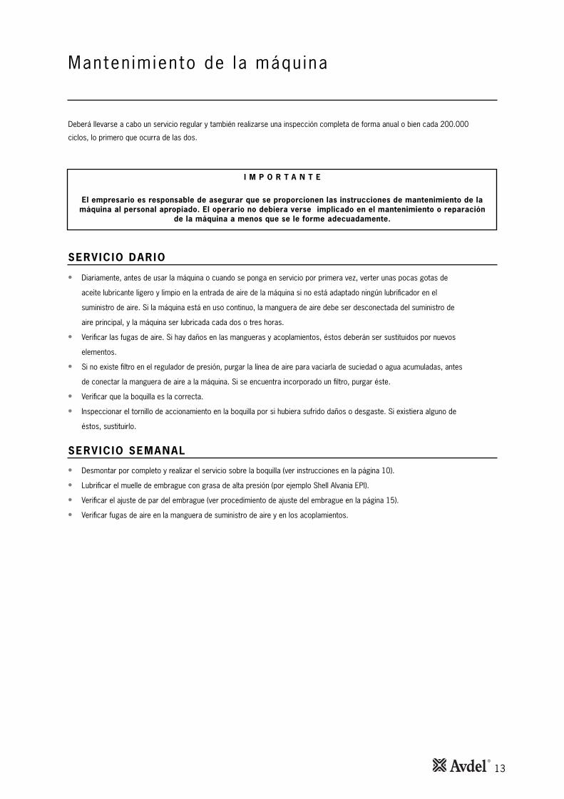
Deberá llevarse a cabo un servicio regular y también realizarse una inspección completa de forma anual o bien cada 200.000
ciclos, lo primero que ocurra de las dos.
• Diariamente, antes de usar la máquina o cuando se ponga en servicio por primera vez, verter unas pocas gotas de
aceite lubricante ligero y limpio en la entrada de aire de la máquina si no está adaptado ningún lubrificador en el
suministro de aire. Si la máquina está en uso continuo, la manguera de aire debe ser desconectada del suministro de
aire principal, y la máquina ser lubricada cada dos o tres horas.
• Verificar las fugas de aire. Si hay daños en las mangueras y acoplamientos, éstos deberán ser sustituidos por nuevos
elementos.
• Si no existe filtro en el regulador de presión, purgar la línea de aire para vaciarla de suciedad o agua acumuladas, antes
de conectar la manguera de aire a la máquina. Si se encuentra incorporado un filtro, purgar éste.
• Verificar que la boquilla es la correcta.
• Inspeccionar el tornillo de accionamiento en la boquilla por si hubiera sufrido daños o desgaste. Si existiera alguno de
éstos, sustituirlo.
• Desmontar por completo y realizar el servicio sobre la boquilla (ver instrucciones en la página 10).
• Lubrificar el muelle de embrague con grasa de alta presión (por ejemplo Shell Alvania EPI).
• Verificar el ajuste de par del embrague (ver procedimiento de ajuste del embrague en la página 15).
• Verificar fugas de aire en la manguera de suministro de aire y en los acoplamientos.

14
DATOS DE SEGURIDAD DE LA GRASA DELIT IO MOLY EP3753
Datos de segur idad (Grasa )
Primeros auxilios
PIEL:
Como la grasa es completamente resistente al agua, se elimina mejor con un limpiador cutáneo emulsificante aprobado.
INGESTIÓN:
Hacer que la persona beba 30ml de leche de magnesia, preferiblemente en una taza de leche.
OJOS:
Irritante pero no peligrosa. Irrigar con agua y buscar atención médica.
Incendio
PUNTO DE INFLAMACIÓN: Por encima de 220°C.
No está clasificada como inflamable.
Medios extintores apropiados: CO2, Halón o rociado de agua si es aplicado por un operario experimentado.
Medio ambiente
Recoger para quemar o desechar en un lugar apropiado.
Manejo
Usar crema de barrera o guantes resistentes al aceite.
Almacenaje
Lejos del calor y de agentes oxidantes.
Para lubrificar aquellos elementos internos de la máquina diferentes a los anteriormente descritos, utilizar grasa de Litio Moly EP3753
(número de pieza 07992-00020)

15
Manten imiento
PARA REAJUSTAR EL PAR DEL EMBRAGUE
• Asegúrese de que se selecciona el muelle de embrague del color correcto con el fin de obtener el par requerido.
• Habiendo fijado un espacio de separación mínimo entre el anillo de ajuste 71 y el anillo elástico de retención 72, y
utilizando la llave para embrague, girar 71 (sentido antihorario) hasta haber completado el número requerido de vueltas
completas con el fin de obtener el par requerido tal como se indica en la tabla que aparece más abajo.
• Las cifras de color blanco sobre fondo negro indican el número de vueltas. Las cifras de color negro sobre fondo blanco
indican el par esperado en lbf ins.
DETALLES EMBRAGUE 74110Nº DE PIEZADEL MUELLE
COLOR DELMUELLE
1 2 3 4 5 6 7 8 9 10 11 12 13 14
Nº DE VUELTAS / lb f insNº DE PIEZA DEEMBRAGUE NO AJUSTADO
30 33 38 45 50 56 61 64 - - - - - -- 20 23 24 25 28 30 32 32 36 40 40 42 -- 9 10 10 14 15 15 15 16 17 18 19 20- - - - - - - - - - - - 2 4
15 16 17 18- - - -- - - -- - - -5 7 7 8
84110-15000 84110-15001 AZUL84100-15000 84100-15001 VERDE84100-15010 84100-15011 ROJO84100-15020 84100-15021 AMARILLO

16
CONJUNTO EMBRAGUE
Manten imiento
LISTA DE COMPONENTES DEL CONJUNTO DE EMBRAGUE
Nº DE PIEZA
AVDEL
Nº DE PIEZAPROVEEDOR
RE-CAMBIOS
COMPO-
NENTE DESCRIPCIÓN CANT.
111021-001483966921157021-001483266922167021-001483866927
2177021-0014833273636687021-001483421804
197021-0014837669234110051-001488448665112051-011488731775100051-001488133796148021-001483106707158021-001483006717
1168021-00148354812272378021-001488222737
188021-0014833898348119021-0014838969239109021-0014837979249
1198021-00148369792592129021-001483428179
139021-0014832170389414149021-001488042799
187021-01148318983011
LEVA EMBRAGUE
PASADOR EMBRAGUE
MANGUITO DE RETENCIÓN
ANILLO TÓRICO
RODAMIENTO (5 mm)
TAPA DE RODAMIENTO
MUELLE (VERDE)
MUELLE (AMARILLO)
MUELLE (AZUL)
ARANDELA DE FIJACIÓN
ANILLO DE AJUSTE
ANILLO ELÁSTICO DE RETENCIÓN
RODAMIENTO
ESPACIADOR
CONJUNTO EMBRAGUE EJE
ARANDELA DE EMPUJE
VÍA DE EMPUJE
RODILLO
MUELLE
RODAMIENTO DE ACERO
CONJUNTO EMBRAGUE
DESMONTAJE
Los números de componentes en Negrita se refieren a la ilustración.
• Desatornillar la carcasa del embrague 103 (rosca lado izquierdo)
• Retirar la sujeción y las arandelas de muelle.
• Retirar el conjunto de embrague 110.
• Utilizando la llave suministrada para embrague, girar el anillo de ajuste 71 hasta que se consiga una distancia mínima
entre 71 y el anillo elástico de retención 72.
• Utilizando unos alicates adecuados para el anillo elástico de retención, extraer 72.
• Retirar el anillo de ajuste 71, así como los elementos 70, 73, 84.
• Retirar el muelle de embrague 56, 57, ó 69.
• Montar en orden inverso, asegurando que la carcasa del embrague 103 queda apretada con el par correcto (6.8Nm) tal
como se muestra en el dibujo de conjunto 74110-12000 (s).
1 2 7 36 40 43 56 57 69 7170
99 98 97 95 94 93 84 73 72
110
17
CONJUNTO DE CAJA DE ENGRANAJES
Manten imiento
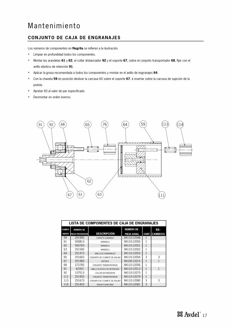
Los números de componentes en Negrita se refieren a la ilustración.
• Limpiar en profundidad todos los componentes.
• Montar las arandelas 61 y 62, el collar distanciador 92 y el soporte 67, sobre el conjunto transportador 68, fijar con el
anillo elástico de retención 91.
• Aplicar la grasa recomendada a todos los componentes y montar en el anillo de engranajes 64.
• Con la chaveta 59 en posición deslizar la carcasa 60 sobre el soporte 67, e insertar sobre la carcasa de sujeción de la
pistola.
• Apretar 60 al valor de par especificado.
• Desmontar en orden inverso.
LISTA DE COMPONENTES DE CAJA DE ENGRANAJES
NÚMERO DE
PIEZA AVDEL
NÚMERO DE
PIEZA PROVEEDOR
RE-CAMBIOS
COMPO-
NENTE DESCRIPCIÓN CANT.184021-0114839915295105021-0114831800516115021-0114836700526125021-0114838515236135021-0114837415246
3345021-01148366152561151021-0014838915276
165021-01148387272861131021-011483532419
137021-0114831575129197021-01148359152111
3308021-01148376152311318021-01148304152411
CHAVETA CUADRADA
ARANDELA
ARANDELA
ARANDELA
ANILLO DE ENGRANAJES
CONJUNTO DE COJINETE DE AGUJAS
SOPORTE
CONJUNTO TRANSPORTADOR
ANILLO ELÁSTICO DE RETENCIÓN
COLLAR DISTANCIADOR
CONJUNTO TRANSPORTADOR
CONJUNTO DE COJINETE DE AGUJAS
RUEDA PLANETARIA
91
62
636167
6892
111
64 59 1137665 114

18
CONJUNTO MOTOR
Manten imiento
Los números de componentes indicados en Negrita hacen referencia a la ilustración.
• Montar el soporte de placas posterior 48 sobre la espiga posterior del rotor 50, aplicando presión a la vía interior del
soporte 47, presionar para conseguir la distancia de separación que se muestra.
• Montar los álabes 51 (por 5) al rotor 50, deslizar el cilindro 49 sobre el conjunto.
• Colocar el soporte de placas frontal 52 sobre la espiga frontal de 50. Mientras se sostiene la espiga posterior de 50
aplicar presión a la vía interior del soporte 54, presionar sobre la espiga frontal.
• Colocar el alojamiento de soporte posterior 46 a la parte posterior del conjunto.
• Colocar el alojamiento de soporte frontal 53 a la parte frontal del conjunto.
LISTA DE COMPONENTES DEL CONJUNTO MOTOR
NÚMERO DE PIEZA
DE AVDEL
NÚMERO DE PIEZA
DE PROVEEDOR
RE-CAMBIOS
COMPO-
NENTE DESCRIPCIÓN CANT.
163021-0114834750354173021-0114831765264
2183021-01148396005741193021-0114832765284
104021-0114830200594114021-0114836715205
01524021-01148332503151134021-0114833765225
144021-01148347652352154021-011488634645
128021-01148393152711
CONJUNTO MOTOR
ALOJAMIENTO – SOPORTE POSTERIOR
SOPORTE
SOPORTE PLACA POSTERIOR
CILINDRO
ROTOR
ÁLABES - ROTOR
SOPORTE PLACA FRONTAL
ALOJAMIENTO – SOPORTE FRONTAL
SOPORTE
PIÑÓN ROTOR
LA POSICIÓN DE LA MUESCA DEL ÁLABE NO ES IMPORTANTE.
MDIMENSIÓN MÁXIMA DESPUÉS DE QUE ELSOPORTE SE HAYA PRESIONADO SOBRE EL ROTOR.
0.0400.025
45
117 54 53 52 49 51 50 48 4746
AVISOCUANDO SE MONTE O SE REALICE EL SERVICIO DEL MOTOR SIN ACEITE, ESTÁ PROHIBIDOFUMAR. LOS ÁLABES DEL ROTOR CONTIENEN P.T.F.E. Y A TEMPERATURAS POR ENCIMADE 300° LA INHALACIÓN DE LOS VAPORES RESULTANTES PUEDEN CAUSAR UNAREACCIÓN ALÉRGICA TEMPORAL. DEBERÁN TOMARSE PRECAUCIONES CUANDO SEEXTRAIGAN LOS RESIDUOS DE P.T.F.E. DEL SILENCIADOR SINTERIZADO. LAVARSESIEMPRE LAS MANOS ANTES DE TOCAR CIGARRILLOS, PIPAS, ALIMENTOS, ETC.

19
AJUSTE DE LA VARILLA EMPUJADORA
Manten imiento
• Aplicar cuñas y espaciadores para obtener un máximo movimiento axial del embrague de 1,3 mm
Nota: Las cuñas deben ser adyacentes a la superficie de sujeción.
• Aplicar presión en dirección de la flecha (A).
• Aplicar presión a la varilla empujadora (B) hasta que se note un tope duro. Medir la dimensión X.
• Obtener la dimensión especificada limando la varilla empujadora (B).
XB
A
7.0 mm7.2
20
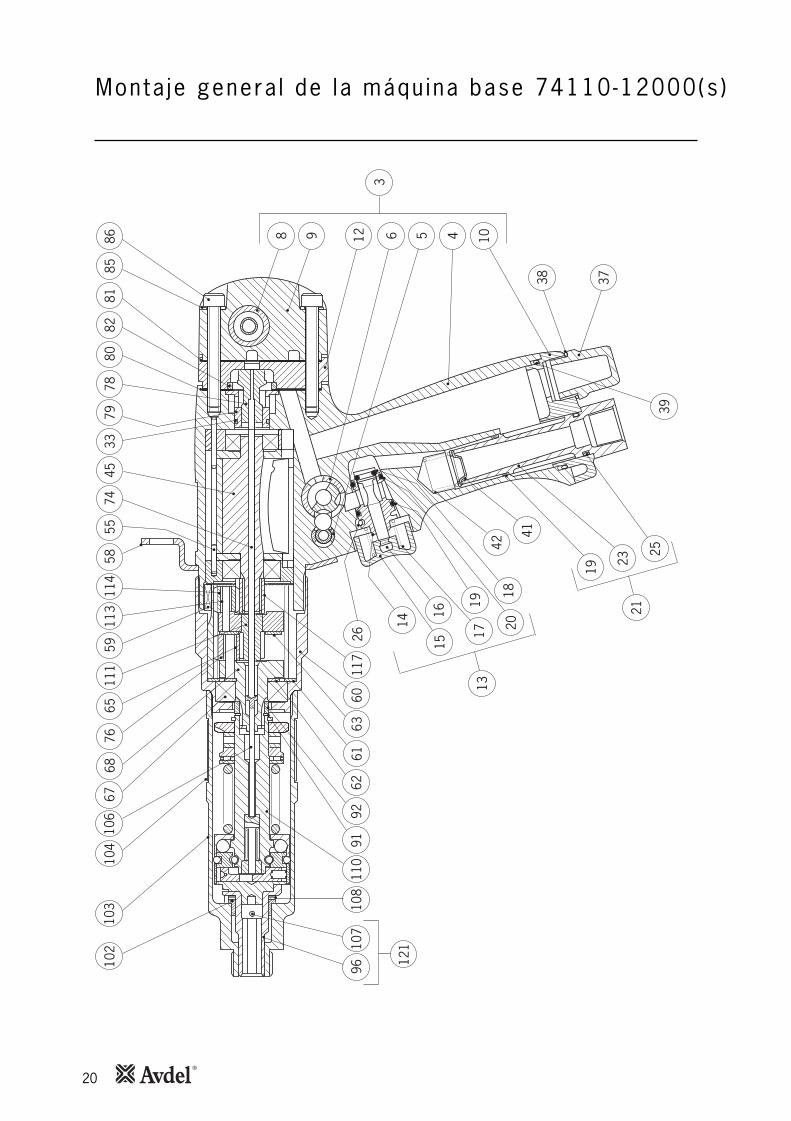
Monta je genera l de la máqu ina base 74110-12000(s )10
210
310
410
667
6876
6559
5855
4533
7978
7411
411
311
180
8185
8682
8 9 63
512 4 10
38 37
3925
2321
19
41
4220
18
1719
1516
26
14
6063
6162
9291
108
107
121
9611
011
7
13

21
L is ta de componentes para 74110-12000(s )
CO
MPO
-N
ENTE
Nº D
E PI
EZA
DES
CR
IPC
IÓN
CAN
T.RE
-CA
MBI
OS
CO
MPO
-N
ENTE
Nº D
E PI
EZA
DES
CR
IPC
IÓN
CAN
T.RE
-CA
MBI
OS
LIS
TA
DE C
OM
PO
NEN
TES
74
11
0-1
20
00
14 702 1- 001 48
11
5 702 1- 001 482
11 002 1- 011 48
31
2 002 1- 011 484
13 002 1- 011 48
51
4 002 1- 011 486
16 702 1- 001 48
71
5 002 1- 011 488
16 002 1- 011 48
91
7 002 1- 011 480 1 11
18002 1- 011 48
2 11
90021- 011 483 1
101021-011 48
4 11
11 02 1- 011 485 1
121 02 1- 011 48
6 11
31 02 1- 011 487 1
141 02 1- 011 48
8 11
51 02 1- 011 489 1
161 02 1- 011 48
0 21
71 02 1- 011 481 2 22
181 02 1- 011 48
3 2 241
91 02 1- 011 485 2
102 02 1- 011 48
6 21
12 02 1- 011 487 2
122 02 1- 011 48
8 21
32 02 1- 011 489 2
142 02 1- 011 48
0 3
152021-01148
131
62021-0114823
372021-01148
331
82021-0114843
192021-01148
532
177021-00148
631
03021-0114873
113021-01148
831
23021-0114893
66
87021-0014804
133021-01148
141
43021-0114824
197021-00148
341
53021-0114844
163021-0114 8
541
73021-0114 864
21
83021- 0114 874
11
93021-0114 884
104021-0114 8
941
14021-0114 805
015
24021-0114 815
11
34021-0114 825
144021-0114 8
352
154021-0114 8
451
64021-0114 855
110051-0014 8
651
12051-0014 875
174021-0114 8
851
84021-0114 895
194021-0114 8
06
LEVA
EM
BRAG
UEPA
SADO
R EM
BRAG
UESU
BCO
NJU
NTO
ASA
Y C
ASQ
UILL
O P
ISTO
LACA
RCAS
A AS
A PI
STO
LACA
SQUI
LLO
DE
RETE
NCI
ÓN
CASQ
UILL
O V
ÁLVU
LA IN
VERS
IÓN
MAN
GUI
TO D
E RE
TEN
CIÓ
NCA
SQUI
LLO
VÁL
VULA
TAPA
FIN
ALTA
PA D
E SA
LIDA
PIEZ
A DE
EXT
ENSI
ÓN
SUBC
ON
JUN
TO G
ATIL
LOCA
SQUI
LLO
VÁL
VULA
BOTÓ
N G
ATIL
LOVÁ
LVUL
A EJ
EM
UELL
EAN
ILLO
TÓ
RICO
ANIL
LO T
ÓRI
COAN
ILLO
TÓ
RICO
SUBC
ON
JUN
TO P
ERN
O E
NTR
ADA
AIRE
PE
RNO
EN
TRAD
A AI
RE
ANIL
LO T
ÓRI
COPA
SADO
R DE
MUE
LLE
ANIL
LO T
ÓRI
COAN
ILLO
TÓ
RICO
RODA
MIE
NTO
TAPA
MUE
LLE
EJE
DE R
ETEN
CIÓ
NAN
ILLO
TÓ
RICO
VÁLV
ULA
DE IN
VERS
IÓN
ANIL
LO D
E RE
TEN
CIÓ
NAN
ILLO
TÓ
RICO
SILE
NCI
ADO
RAN
ILLO
TÓ
RICO
ANIL
LO T
ÓRI
CO
RODA
MIE
NTO
(5 m
m)
FILT
RO D
E AI
REM
UELL
ETA
PA D
E RO
DAM
IEN
TOAN
ILLO
TÓ
RICO
CON
JUN
TO M
OTO
RAL
OJA
MIE
NTO
– S
OPO
RTE
POST
ERIO
RSO
PORT
ESO
PORT
E PL
ACA
POST
ERIO
RCI
LIN
DRO
ROTO
R ÁL
ABES
- RO
TOR
SOPO
RTE
PLAC
A FR
ON
TAL
ALO
JAM
IEN
TO –
SO
PORT
E FR
ON
TAL
SOPO
RTE
PASA
DOR
ESPI
RAL
MUE
LLE
(VER
DE)
MUE
LLE
(AM
ARIL
LO)
ANIL
LO D
E SU
SPEN
SIÓ
NCH
AVET
A CU
ADRA
DACA
RCAS
A EN
GRA
NAJ
ES

22
Monta je genera l de la máqu ina base 74110-12000(s )10
210
310
410
667
6876
6559
5855
4533
7978
7411
411
311
180
8185
8682
8 9 63
512 4 10
38 37
3925
2321
19
41
4220
18
1719
1516
26
14
6063
6162
9291
108
107
121
9611
011
7
13

23
L is ta de componentes para 74110-12000(s )
CO
MPO
-N
ENTE
Nº D
E PI
EZA
DES
CR
IPC
IÓN
CAN
T.RE
-CA
MBI
OS
CO
MPO
-N
ENTE
Nº D
E PI
EZA
DES
CR
IPC
IÓN
CAN
T.RE
-CA
MBI
OS
LIS
TA
DE C
OM
PO
NEN
TES
74
11
0-1
20
00
105 021-0 1148
161
15 021-0 114826
125 021-0 11 48
361
35 021-0 11 4846
33
45 021-0 11 4856
155 021-0 11 48
661
151 021-0 01 48
761
65 021-0 11 4886
100 051-0 11 48
961
48 021-0 01 4807
158 021-0 01 48
171
168 021-0 01 48
273
378 021-0 01 48
3 71
75 021-0 11 484 7
185021-0 11 48
5 73
95021-011 486 7
106021-0 1148
7 71
16021-0 11488 7
126021-0 1148
9 71
36021-0 114808
146021-0 1148
181
5602 1-0 114828
166021-0 1148
381
88021-0 014848
276021-0 1148
582
86021-0 114868
196021-0 1148
782
07021-0 114888
217021-0 1148
981
27021-0 114809
11
31021-0014819
137021-01148
291
19021-0014839
109021-00148
491
198021-00148
591
10021-0014869
21
29021-0014879
139021-00148
8941
4149021-00148
99 100
101021-00148
1011
47021-01148201
157021-01148
3011
67021-01148401 105
177021-01148
601 107
187021-01148
801 109
197021-01148
0111
08021-01148111 112
33
18021-01148311
328021-01148
411 115
116
138021-01148
711 118
148021-01148
0211
54021-00148121
ARAN
DELA
ARAN
DELA
ARAN
DELA
ANIL
LO D
E EN
GRA
NAJ
ESCO
NJU
NTO
DE
COJIN
ETE
DE A
GUJ
ASAR
ANDE
LASO
PORT
ECO
NJU
NTO
TRA
NSP
ORT
ADO
RM
UELL
E (A
ZUL)
ARAN
DELA
DE
FIJA
CIÓ
NAN
ILLO
DE
AJUS
TEAN
ILLO
ELÁ
STIC
O D
E RE
TEN
CIÓ
NRO
DAM
IEN
TOVA
RILL
A EM
PUJA
DORA
PLAC
A DE
ESP
ECIF
ICAC
ION
ESRU
EDA
PLAN
ETAR
IAJU
NTA
DE
ESTA
NQ
UEID
ADCO
NJU
NTO
VÁL
VULA
ELE
VACI
ÓN
CASQ
UILL
O V
ÁLVU
LAJU
NTA
DE
ESTA
NQ
UEID
ADJU
NTA
DE
ESTA
NQ
UEID
ADAN
ILLO
CIN
TA A
UTO
ADHE
SIVA
ESPA
CIAD
OR
ARAN
DELA
DE
FIJA
CIÓ
NTO
RNIL
LO M
5 X
40VÁ
LVUL
A DE
CIE
RRE
ANIL
LO E
LÁST
ICO
DE
RETE
NCI
ÓN
CAPE
RUZA
MUE
LLE
ANIL
LO E
LÁST
ICO
DE
RETE
NCI
ÓN
COLL
AR D
ISTA
NCI
ADO
RCO
NJU
NTO
EM
BRAG
UE E
JEAR
ANDE
LA D
E EM
PUJE
VÍA
DE E
MPU
JESU
JECI
ÓN
RODI
LLO
MUE
LLE
RODA
MIE
NTO
DE
ACER
O
CON
JUN
TO C
ARCA
SA E
MBR
AGUE
SOPO
RTE
DE E
JECA
RCAS
A DE
EM
BRAG
UEAN
ILLO
DE
MUE
LLE
VARI
LLA
EMPU
JADO
RA
CUÑ
AS
CON
JUN
TO E
MBR
AGUE
CON
JUN
TO T
RAN
SPO
RTAD
OR
CON
JUN
TO D
E CO
JINET
E DE
AG
UJAS
RUED
A PL
ANET
ARIA
PIÑ
ÓN
RO
TOR
ETIQ
UETA
VÁL
VULA
INVE
RSA
SUJE
CIÓ
N

24
D iagnóst ico de aver ías
SÍ P FEROIDEMERELBISOP ASUACAMOTN ÁGINA
La máquina Cojinetes de empuje o arandelas Sustituir 10realiza la de empuje desgastadosinversión de giro Roscas de insertos sucias Cambiar lote de insertos
antes de que se Tornillo de accionamiento desgastado Sustituir 10coloque el inserto Falta de lubricación de tornillo de Lubrificar adecuadamente tornillo
accionamiento (Sólo Nutserts® estándar) de accionamiento
Muelle de empuje no montado Montar muelle de empuje 10Ajuste demasiado bajo de par de embrague Ajustar al valor correcto 15Presión / volumen de aire insuficiente Verificar suministro de aire / acoplamientos 8
La máquina Presión de aire insuficiente Ajustar presión de aire en la base 8funciona del asa 5 -6.5 bar máximolentamente Diámetro interior de manguera incorrecto Asegurarse de que el diámetro interior de la 8
manguera es de 6.4mm mínimo
Volumen de aire insuficiente Asegurarse de que no hay limitación en el 8suministro de aire ni en las conexiones
Máquina no lubrificada correctamente Lubrificar según instrucciones 12internamente
La máquina no Máquina no lubrificada adecuadamente Lubrificar, apretar el gatillo varias veces 12se pone en Presión / volumen de aire limitado Asegurarse de que no hay restricción en el 8marcha suministro de aire
La máquina funciona Varilla empujadora demasiado larga Sustituir por una de longitud correcta 19permanentemente Suministro de aire insuficiente Ajustar presión / volumen de aire 5en modo inverso
La máquina funciona Faltan varillas empujadoras / rodillo de aguja Sustituir donde sea necesario 19permanentemente Varilla empujadora demasiado corta Sustituir 19en sentido directo
No se tira de los Ajuste de par demasiado bajo Ajustar al valor correcto 15insertos hacia arriba Presión / volumen de aire insuficiente Ajustar presión / volumen de aire 8
sotcerroc sotresni ranoicceleSnarraga on sotresnI
Falta de lubricación en inserto Cambiar lote de insertos
Falta de lubricación de tornillo de Lubrificar adecuadamente tornillo de
accionamiento (Sólo Nutserts® estándar) accionamiento
Rosca de inserto limitada Cambiar insertos
Rosca de tornillo de accionamiento Sustituir tornillo de accionamiento 10desgastada
Tornillo de accionamiento / Sustituir por tornillo de accionamiento / 10sotcerroc otresnisotcerrocni otresni
Otros síntomas o fallos deberán ser notificados a su distribuidor autorizado Avdel o a su centro de reparaciones local.
Continúa al dorso

25
D iagnóst ico de aver ías
SÍ P FEROIDEMERELBISOP ASUACAMOTN ÁGINA
Insertos Nutserts® Nutserts® strestuN raipmiLsoicus ®
estándar caen Ajuste de par de embrague Ajustar al valor correcto 15demasiado bajo
Espesor de aplicación por debajo Cambiar a apriete de inserto
del mí odadnemocer otcerrocomin
Tamaño excesivo de agujero en aplicación Corregir tamaño de agujero en aplicación
Tornillos de Ajuste de par de embrague demasiado alto Ajustar al valor correcto 15accionamiento Tornillo de accionamiento no lubrificado Lubricar regularmente tornillo de accionamiento
desgastados Cuando se usen Nutserts® estándar
Insertos no lubrificados Cambiar lote de insertos
No se sostiene la máquina adecuadamente Asegurar que la máquina se sostiene
perpendicular a la aplicación
Rosca de tornillo de accionamiento / Sustituir por tornillo de accionamiento / 10sotcerroc otresniatcerrocni otresni
Roscas de inserto limitadas Cambiar lote de insertos
Otros síntomas o fallos deberán ser notificados a su distribuidor autorizado Avdel o a su centro de reparaciones local.

26
Notas

Fecha de emisión
A. Seewraj - Director de diseño de productos - Herramientas de automatización
Esta caja contiene una máquina con alimentación que estáen conformidad con la Directiva de Máquinas 2006/42/EC.La ‘Declaración de Conformidad’ se encuentra en el interior.
Dec larac ión de Conformidad
Nosotros, Avdel UK Limited; Watchmead Industrial Estate, Welwyn Garden City, Hertfordshire, AL7 1LY declaramos bajo
nuestra única responsabilidad que el producto:
Modelo 74110
Nº de Serie ................................................
Al que se refiere esta declaración cumple con las siguientes normas:
EN ISO 12100 - parte 1 & 2
BS EN ISO 8662 - parte 6 BS EN ISO 11202
BS EN ISO 3744 BS EN 982
ISO EN 792 - parte 13-2000 BS EN 983
Siguiendo las disposiciones de la Directiva de Máquinas 2006/42/EC.
Since 1 936 2010 Since 1922
www.avdel-global.comwww.infastech.com
02.2
011
• ©
201
0 In
fast
ech
Autosert® (equipment), Avbolt ®, Avdel®, Avdelmate®, Avdel TX2000®, Avdelok®, Avex®, Avibulb®, Avinox®, Avinut™, Avlug®, Avmatic®, Avplas®,Avseal®, Avsert®, Avtainer®, Avtronic®, Briv®, Bulbex®, Chobert®, Eurosert®, Fastriv®, Finsert®, Genesis®, Grovit®, Hemlok®, Hexsert®, Holding your world together®, Hydra®, Interlock®, Klamp-Tite®, Klamptite KTR®, Kvex®, Maxlok®, Monobolt®, Monobulb ®, Neobolt®, Nutsert®, Nutsert SQ®, Portariv®, Rivmatic®, Rivscrew®, Speed Fastening®, Squaresert®, Stavex®, Supersert®, Thin Sheet Nutsert®, Titan®, T-Lok®, TLR®, TSN®, TX2000®, Versa-Nut®, Viking® and Viking 360® are trademarks of Avdel UK Limited. Infastech™ and Our Technology, Your Success™ are trademarks of Infastech Intellectual Properties Pte Ltd. The names and logos of other companies mentioned herein may be trademarks of their respective owners. This document is for informational purposes only. Infastech makes no warranties, expressed or implied, in this document. Data shown is subject to change without prior notice as a result of continuous product development and improvement policy. Your local Avdel representative is at your disposal should you need to confirm latest information.
AUSTRALIAInfastech (Australia) Pty Ltd.891 Wellington RoadRowvilleVictoria 3178Tel: +61 3 9765 6400Fax: +61 3 9765 [email protected]
CANADAAvdel Canada Limited1030 Lorimar DriveMississaugaOntario L5S 1R8Tel: +1 905 364 0664Fax: +1 905 364 [email protected]
CHINAInfastech (China) Ltd.RM 1708, 17/F., Nanyang Plaza,57 Hung To Rd., Kwun TongHong KongTel: +852 2950 0631Fax: +852 2950 [email protected]
FRANCEAvdel France S.A.S.33 bis, rue des ArdennesBP4 75921 Paris Cedex 19Tel: +33 (0) 1 4040 8000Fax: +33 (0) 1 4208 [email protected]
GERMANYAvdel Deutschland GmbHKlusriede 2430851 LangenhagenTel: +49 (0) 511 7288 0Fax: +49 (0) 511 7288 [email protected]
INDIAInfastech Fastening Technologies India Private LimitedPlot No OZ-14, Hi Tech SEZ,SIPCOT Industrial Growth Center,Oragadam, Sriperumbudur Taluk, Kanchipuram District,602105 TamilnaduTel: +91 44 4711 8001Fax: +91 44 4711 [email protected]
ITALYAvdel Italia S.r.l.Viale Lombardia 51/5320047 Brugherio (MI)Tel: +39 039 289911Fax: +39 039 [email protected]
JAPANInfastech Kabushiki KaishaCenter Minami SKY, 3-1 Chigasaki-Chuo, Tsuzuki-ku,Yokohama-city, Kanagawa PrefectureJapan 224-0032Tel: +81 45 947 1200Fax: +81 45 947 [email protected]
MALAYSIAInfastech (Malaysia) Sdn BhdLot 63, Persiaran Bunga Tanjung 1,Senawang Industrial Park70400 SerembanNegeri SembilanTel: +606 676 7168Fax: +606 676 [email protected]
SINGAPOREInfastech (Singapore) Pte Ltd. 31 Kaki Bukit Road 3#05-03/06 TechlinkSingapore, 417818Tel: +65 6372 5653Fax: +65 6744 [email protected]
SOUTH KOREAInfastech (Korea) Ltd.212-4, Suyang-Ri,Silchon-Eup, Kwangju-City,Kyunggi-Do, Korea, 464-874Tel: +82 31 798 6340Fax: +82 31 798 [email protected]
SPAIN Avdel Spain S.A.C/ Puerto de la Morcuera, 14Poligono Industrial Prado OveraCtra. de Toledo, km 7,828919 Leganés (Madrid)Tel: +34 91 3416767Fax: +34 91 [email protected]
TAIWANInfastech/Tri-Star LimitedNo 269-7, Baodong Rd, Guanmiao Township,71841 Tainan County,Taiwan, R.O.CTel: +886 6 596 5798 (ext 201)Fax: +886 6 596 [email protected]
UNITED KINGDOMAvdel UK LimitedPacific House2 SwiftfieldsWatchmead Industrial EstateWelwyn Garden CityHertfordshire AL7 1LYTel: +44 (0) 1707 292000Fax: +44 (0) 1707 [email protected]
USAAvdel USA LLC614 NC Highway 200 SouthStanfield, North Carolina 28163Tel: +1 704 888 7100Fax: +1 704 888 [email protected]
Manual No. Issue Change Note No. Date
AA 03/046
AB 07/176
AC 11/07207900-00794

I n s t ruc t i on Manua lOr ig i na l I ns t ruc t i on
Threaded Inser t Power Too l
74110


3
Contents
Safety Rules 4
Tool Specifications 5Tool Dimensions 5
Intent of UseTool Selection 6 & 7
Putting into ServiceAir supply 8Operating Procedure 8Clutch Adjustment 9Accessories 9
Nose AssembliesFitting Instructions 10Servicing Instructions 10Nose Assembly Components 11 & 12
Servicing the ToolDaily Servicing 13Weekly Servicing 13
Safety Data (Grease) 14
MaintenanceReset Clutch Torque 15Clutch Assembly 16Gearbox Assembly 17Motor Assembly 18Setting the Push Rod 19
General Assembly of Base Tool 20, 22
Parts List 21, 23
Troubleshooting 24 & 25
Avdel UK Limited policy is one of continuous product development and improvement and we reserve the right to change the specification of any product without prior notice.
WarrantyAvdel installation tools carry a 12 month warranty against defects caused by faulty materials or
workmanship, the warranty period commencing from the date of delivery confirmed by invoice or delivery
note.
The warranty applies to the user/purchaser when sold through an authorised outlet, and only when used for
the intended purpose. The warranty is invalidated if the installation tool is not serviced, maintained and
operated according to the instructions contained in the Instruction and Service Manuals.
In the event of a defect or failure, and at its sole discretion, Avdel undertakes only to repair or replace faulty
components.

4
Sa fe ty Ru les
1 Do not use outside the design intent.
2 Do not use equipment with this tool other than that recommended and supplied by Avdel UK Limited.
3 Any modification undertaken by the customer to the tool/machine, nose assemblies, accessories or any equipment
supplied by Avdel UK Limited or their representatives, shall be the customer’s entire responsibility. Avdel UK Limited
will be pleased to advise upon any proposed modification.
4 The tool/machine must be maintained in a safe working condition at all times and examined at regular intervals for
damage and function by trained competent personnel. Any dismantling procedure shall be undertaken only by
personnel trained in Avdel UK Limited procedures. Do not dismantle this tool/machine without prior reference to the
maintenance instructions. Please contact Avdel UK Limited with your training requirements.
5 The tool/machine shall at all times be operated in accordance with relevant Health and Safety legislation. In the U.K.
the “Health and Safety at Work etc. act 1974” applies. Any question regarding the correct operation of the
tool/machine and operator safety should be directed to Avdel UK Limited.
6 The precautions to be observed when using this tool/machine must be explained by the customer to all operators.
7 Always disconnect the airline from the tool/machine inlet before attempting to adjust, fit or remove a nose
assembly.
8 Do not operate a tool/machine that is directed towards any person(s).
9 Ensure that vent holes do not become blocked or covered and that hoses are always in good condition.
10 The operating pressure shall not exceed 6.3 bar - 94 lbf/in2.
11 Do not operate the tool without full nose equipment in place.
12 When using the tool, the wearing of safety glasses is required both by the operator and others in the vicinity to
protect against fastener projection, should a fastener be placed ‘in air’. We recommend wearing gloves if there are
sharp edges or corners on the application.
13 Take care to avoid entanglement of loose clothes, ties, long hair, cleaning rags etc. in the moving parts of the tool
which should be kept dry and clean for best possible grip.
14 When carrying the tool from place to place keep hands away from the trigger/lever to avoid inadvertent start up.
15 Always adopt a firm footing or a stable position before operating the tool and be aware of a torque reaction on the
hands when the tool is operating, particularly during the reversing sequence. Grip the tool firmly to be able to
counter the torque reaction, but not too tightly.
16 Keep hands away from the rotating drive screw and the nose end of the tool. If a fastener becomes jammed on the
drive screw, shut off the air supply and drain the supply line to the tool before attempting to dislodge it.
17 The tool is not electrically insulated.
18 This tool is not designed for use in combustible or explosive atmospheres.
This instruction manual must be read with particular attention to the following safety rules, by anyperson installing, operating, or servicing this tool.

5
Tool Spec i f icat ion
Too l D imens ions
Spec i f ica t ions
Air Pressure Minimum - Maximum 4-6.3 bar (60/94 lbf/in2)
Free Air Volume Required @ 6.3 bar / 94 lbf/in2 7.5 litres/sec
Motor Speed @ 75 lb/in2 minimum 600 rpm (clockwise)
Cycle time Approx 3 seconds
Noise Level 82 dB(A)
Weight Without nose equipment 1.6 kg 3.53 lb)
Vibration Less than 2.5 m/s2 (8 ft/s2 )
263
A
B
10.350
170
6.70
0
Dimensions shown in bold are millimetres. Other dimensions are in inches

6
Tool Se lect ion
I n ten t o f Use
The pneumatic 74110 type tool is designed to place Avdel® threaded inserts at high speed making it ideal for batch or
flow-line assembly in a wide variety of applications throughout all industries.
Use the selection table opposite to select a complete tool which will be fitted with the correct nose assembly for the
threaded insert selected. ‘A’ and ‘B’ dimensions will help you assess the accessibility of your application.
It is also possible to order the base tool only (part number 74110-12000). For details of Nose Assemblies see pages 11
and 12.
3/16 BSW 20 - 25 84100-15000 13 12 1/2 15/32 07556-09816 74110-000161/4 BSW 25 - 30 84100-15000 13 15 1/2 19/32 07566-09818 74110-000185/16 BSW 40 - 45 84110-15000 14 14 9/16 9/16 07443-09810 74110-000103/8 BSW 50 - 55 84110-15000 16 10 5/8 13/32 07443-09812 74110-000121/4 BSW 25 - 30 84100-15000 13 15 1/2 19/32 07556-09828 74110-000285/16 BSW 40 - 45 84110-15000 14 14 9/16 9/16 07443-09820 74110-000203/8 BSW 50 - 55 84110-15000 16 10 5/8 13/32 07443-09822 74110-00022
4 UNC 5 - 7 84100-15020 13 12 1/2 15/32 07556-09854 74110-000546 UNC 9 - 11 84100-15010 13 12 1/2 15/32 07556-09856 74110-000568 UNC 13 - 15 84100-15010 13 10 1/2 13/32 07556-09858 74110-00058
10 UNC 20 - 25 84100-15000 13 12 1/2 15/32 07556-09850 74110-000506 UNF 9 - 11 84100-15010 13 12 1/2 15/32 07556-09876 74110-000768 UNF 13 - 15 84100-15010 13 10 1/2 13/32 07556-09878 74110-00078
10 UNF 20 - 25 84100-15000 13 12 1/2 15/32 07556-09870 74110-000701/4 UNC 25 - 30 84100-15000 13 15 1/2 19/32 07566-09848 74110-000485/16 UNC 40 - 45 84110-15000 14 14 9/16 9/16 07443-09840 74110-000403/8 UNC 50 - 55 84110-15000 16 10 5/8 13/32 07443-09842 74110-000421/4 UNF 25 - 30 84100-15000 13 15 1/2 19/32 07556-09868 74110-000685/16 UNF 40 - 45 84110-15000 14 14 9/16 9/16 07443-09860 74110-000603/8 UNF 50 - 55 84110-15000 16 10 5/8 13/32 07443-09862 74110-00062
6 BA 5 - 7 84100-15020 13 15 1/2 19/32 07556-09836 74110-000364 BA 9 - 11 84100-15010 13 12 1/2 15/32 07556-09834 74110-000342 BA 20 - 25 84100-15000 13 12 1/2 15/32 07556-09832 74110-000320 BA 25 - 30 84100-15000 13 12 1/2 15/32 07556-09830 74110-00030M3 5 - 7 84100-15020 13 12 1/2 15/32 07556-09883 74110-00083M4 13 - 15 84100-15010 13 10 1/2 13/32 07556-09884 74110-00084M5 20 - 25 84100-15000 13 12 1/2 15/32 07556-09885 74110-00085M6 25 - 30 84100-15000 13 15 1/2 19/32 07556-09886 74110-00086M8 40 - 45 84110-15000 14 14 9/16 9/16 07443-09888 74110-00088
M10 50 - 55 84110-15000 16 12 5/8 15/32 07443-09880 74110-00080M4 16 - 18 84100-15010 13 10 1/2 13/32 07556-09184 74110-04084M5 30 - 35 84110-15000 13 12 1/2 15/32 07556-09185 74110-04085M6 35 - 40 84110-15000 13 15 1/2 19/32 07556-09186 74110-04086M4 16 - 18 84110-15010 13 12 1/2 15/32 07556-09284 74110-06084M5 30 - 35 84110-15000 13 12 1/2 15/32 07556-09285 74110-06085M6 40 - 45 84110-15000 16 14 5/8 9/16 07556-09286 74110-06086M8 50 - 55 84110-15000 16 15 5/8 19/32 07443-09288 74110-06088M5 30 - 35 84110-15000 10 13 13/32 1/2 07528-07085 74110-07085M6 40 - 45 84110-15000 13 15 1/2 19/32 07566-09186 74110-04086
74110 TOOL SELECTIONNOSE (see drawing opposite for A & B) TORQUE
SETTING (lbf ins)ØCOMPLETE
TOOL PART NºNOSE ASSY PART N ºA (mm)INSERT
NAME & SERIES B (mm) A (in) B (in)UNSET
CLUTCH PART Nº
STANDARDNUTSERTS(9500)(9538)
L/F THIN SHEET NUTSERT® (9698)
HEXSERT®(9688)
NUTSERT® SQ(GK08)

7
Tool Se lect ion
I n ten t o f Use
74110 TOOL SELECTIONNOSE (see drawing opposite for A & B) TORQUE
SETTING (lbf ins)ØCOMPLETE
TOOL PART NºNOSE ASSY PART NºA (mm)INSERT
NAME & SERIES B (mm) A (in) B (in)UNSET
CLUTCH PART NºTHIN 3/16 BSW 30 - 35 84110-15000 13 10 1/2 13/32 07556-09916 74110-01016SHEET 1/4 BSW 35 - 40 84110-15000 13 131/2 1/2 17/32 07566-09918 74110-01018NUTSERT® 5/16 BSW 50 - 55 84110-15000 14 14 9/16 9/16 07443-09910 74110-01010(9650) 1/4 BSF 35 - 40 84110-15000 13 131/2 1/2 17/32 07556-09928 74110-01028
5/16 BSF 50 - 55 84110-15000 14 14 9/16 9/16 07443-09920 74110-010204 UNC 7 - 9 84100-15020 13 11 1/2 7/16 07556-09954 74110-010546 UNC 16 - 18 84100-15010 13 11 1/2 7/16 07556-09956 74110-010568 UNC 16 - 18 84100-15010 13 12 1/2 15/32 07556-09958 74110-01058
10 UNC 30 - 35 84110-15000 13 10 1/2 13/32 07556-09950 74110-010504 UNF 7 - 9 84100-15020 13 11 1/2 7/16 07556-09974 74110-010746 UNF 16 - 18 84100-15010 13 11 1/2 7/16 07556-09976 74110-010768 UNF 16 - 18 84100-15010 13 12 1/2 15/32 07556-09978 74110-01078
10 UNF 30 - 35 84110-15000 13 10 1/2 13/32 07556-09970 74110-010701/4 UNC 35 - 40 84110-15000 13 131/2 1/2 17/32 07556-09948 74110-01048
5/16 UNC 50 - 55 84110-15000 14 14 9/16 9/16 07443-09940 74110-010401/4 UNF 35 - 40 84110-15000 13 131/2 1/2 17/32 07556-09968 74110-01068
5/16 UNF 50 - 55 84110-15000 14 14 9/16 9/16 07443-09960 74110-010606 BA 7 - 9 84100-15020 13 131/2 1/2 17/32 07556-09936 74110-010364 BA 16 - 18 84100-15010 13 11 1/2 7/16 07556-09934 74110-010342 BA 30 - 35 84110-15000 13 17 1/2 21/32 07556-09932 74110-010320 BA 35 - 40 84110-15000 13 11 1/2 7/16 07556-09930 74110-01030M3 7 - 9 84100-15020 13 11 1/2 7/16 07556-09983 74110-01083M4 16 - 18 84100-15010 13 11 1/2 7/16 07556-09984 74110-01084M5 30 - 35 84110-15000 13 10 1/2 13/32 07556-09985 74110-01085M6 35 - 40 84110-15000 13 131/2 1/2 17/32 07556-09986 74110-01086M8 50 - 55 84110-15000 14 14 9/16 9/16 07443-09988 74110-01088
SUPERSERT® 8 UNC 16 - 18 84100-15010 13 10 1/2 13/32 07552-09558 74110-02058(FB00) 10 UNC 30 - 35 84110-15000 13 12 1/2 15/32 07552-09550 74110-02050
8 UNF 16 - 18 84100-15010 13 10 1/2 13/32 07552-09578 74110-0207810 UNF 30 - 35 84110-15000 13 12 1/2 15/32 07552-09570 74110-020701/4 UNC 45 - 50 84110-15000 13 15 1/2 19/32 07552-09548 74110-020481/4 UNF 45 - 50 84110-15000 13 15 1/2 19/32 07552-09568 74110-02068
M3 16 - 18 84100-15010 13 19 1/2 3/4 07552-09583 74110-02083M4 16 - 18 84100-15010 13 10 1/2 13/32 07552-09584 74110-02084M5 30 - 35 84110-15000 13 11 1/2 7/16 07552-09585 74110-02085M6 45 - 50 84110-15000 13 15 1/2 19/32 07552-09586 74110-02086
LGE FLANGE M4 16 - 18 84100-15010 13 10 1/2 13/32 07556-09184 74110-04084HEXSERT® M5 30 - 35 84110-15000 13 10 1/2 13/32 07557-09285 74110-03085(9498) M6 35 - 40 84110-15000 14 12 9/16 15/32 07556-09186 74110-04086

8
Air Supp ly
Operat ing Procedure
Put t ing in to Serv ice
All tools are operated with compressed air at an optimum pressure of 5.5 bar. We recommend the use of pressure regulators
and automatic oiling/filtering systems on the main air supply. These should be fitted within 3 metres of the tool (see diagram
below) to ensure maximum tool life and minimum tool maintenance.
Air supply hoses should have a minimum working effective pressure rating of 150% of the maximum pressure produced in the
system or 10 bar, whichever is the highest. Air hoses should be oil resistant, have an abrasion resistant exterior and should
be armoured where operating conditions may result in hoses being damaged. All air hoses MUST have a minimum bore
diameter of 6.4 millimetres or 1/4 inch.
Read servicing daily details page 13.
I M P O R T A N TWhen placing Standard Nutserts, lubricate the drive screw of the tool every 25 placings. This is best
achieved by wiping the drive screw with a sponge soaked with STP Lubricant part number 07992-00013.
OPTION 1
• Ensure that the correct nose equipment is fitted.
• Connect the tool to the air supply.
• Place the insert into the prepared hole of the application.
• Locate the drive screw of the tool into the insert.
• Operate the lever. The drive screw will screw into and
collapse the insert, then automatically reverse out.
OPTION 2
• Ensure that the correct nose equipment is fitted.
• Connect the tool to the air supply.
• Screw the insert lip first onto the drive screw of the tool.
• With the insert on the tool, locate it into the prepared
hole of the application.
• Operate the lever. The drive screw will screw into and
collapse the insert, then automatically reverse out.
86
42
0
10121416
TAKE OFF POINTFROM MAIN SUPPLY
STOP COCK(USED DURING MAINTENANCE
OF FILTER/REGULATOR OR LUBRICATION UNITS)
MAIN SUPPLYDRAIN POINT
PRESSURE REGULATORAND FILTER
(DRAIN DAILY)
LUBRICATOR
3 METRES

9
Clutch Ad jus tment
Accessor ies
Put t ing in to Serv ice
If you have ordered a complete tool the clutch will be set for the specified insert.
When purchased as a spare part, the clutch is supplied unset.
Correct clutch setting is necessary to ensure optimum deformation of the insert. If the deformation is insufficient (clutch
torque too low) the insert will rotate in the application. If the deformation is excessive (clutch torque too high) thread distortion
will occur and extensive wear on the drivescrew, may lead to fracture.
For details on how to adjust the clutch refer to maintenance instructions referring to the clutch on page 15.
Two different accessories are available to make the connection to your air supply:
Hose Connector
part nº 07005-00276
Hose Assembly
part nº 07008-000324
TO FIT 6.4 mm (1/4") BORE PIPE
1/4" BSPL = 137 cm

10
F i t t ing Ins t ruct ions
Serv ic ing Ins t ruct ions
Nose Assembl ies
Nose assemblies are specifically designed for each size and type of insert. If you have purchased a complete tool, it will
already be fitted with the correct nose assembly for your insert.
It is essential that the correct nose assembly is fitted prior to operating the tool. By knowing your original complete tool part
number or the details of the insert to be placed, you will be able to order a new complete nose assembly using the selection
table pages 11 and 12.
I M P O R T A N T
The air supply must be disconnected when fitting or removing nose assemblies unless specifically instructed
otherwise.
Before fitting the nose equipment, ensure the clutch on the tool is set to the correct torque for the insert being placed. (Torque
values are on page 7.)
• Where applicable, insert sleeve 8 and thrust spring 9 into nose housing 2.
• Coat thrust washers 3 and thrust bearing 4 with high pressure grease (eg. Shell Alvania E.P.I.) and locate them in the order
shown below into the nose housing 2.
• Where applicable, fit spacer 5 through thrust washers and thrust bearings.
• Insert drive screw 1 through the above assembly.
• Fit drive shaft 6 into the hexagon hole in the drive screw head.
• Insert stop 11 and spring 10 into the front of the base tool.
• Screw adaptor 7 into clutch housing of the base tool (left hand thread).
• Offer up the nose assembly to the adaptor. It will be necessary to rotate the drive screw by hand to line up the hexagon on
the drive shaft 6 with the hexagonal hole in the front jaw of the base tool.
• Screw the nose housing 2 onto the adaptor 7 and tighten with a spanner (left hand thread).
2 8 9
1 6 10
3 4 3 5
11 7
Nose assemblies should be serviced at weekly intervals.
• Remove the complete nose assembly using the reverse procedure to the ‘Fitting Instructions’.
• Any worn or damaged part should be replaced.
• Particularly check wear on drivescrew, thrust washers and thrust bearing.
• Lubricate thrust washers and thrust bearings with high pressure grease (eg Shell Alvania E.P.I.)
• Check springs are not distorted.
• Assemble according to fitting instructions.

11
Nose Assembly Components
Nose Assembl ies
The table below lists all nose assemblies available. Each nose assembly represents a unique assembly of components which
can be ordered individually. Components numbers refer to the text and illustration opposite. We recommend some stock as
items will need regular replacement. Read the nose assemblies servicing instructions opposite carefully. All nose assemblies
also include spring 10 part number 07430-08202 and stop 11 part number 07430-08203.
61 7NOSE ASSY 2 43 5 8 907443-09288 07001-00084 07522-08988 07007-00081 07007-00078 07443-03110 07430-01808 07443-08002 07522-08902 07154-0309207443-09810 07001-00076 07443-06110 07007-00081 07007-00078 07443-03110 07430-01110 07443-08002 - -07443-09812 07001-00099 07443-06112 07007-00081 07007-00078 - 07430-01112 07443-08002 - -07443-09820 07001-00077 07443-06110 07007-00081 07007-00078 07443-03110 07430-01110 07443-08002 - -07443-09822 07001-00098 07443-06112 07007-00081 07007-00078 - 07430-01112 07443-08002 - -07443-09840 07001-00078 07443-06110 07007-00081 07007-00078 07443-03110 07430-01110 07443-08002 - -07443-09842 07001-00106 07443-06112 07007-00081 07007-00078 - 07430-01112 07443-08002 - -07443-09860 07001-00079 07443-06110 07007-00081 07007-00078 07443-03110 07430-01110 07443-08002 - -07443-09862 07001-00105 07443-06112 07007-00081 07007-00078 - 07430-01112 07443-08002 - -07443-09880 07001-00100 07443-06810 07007-00082 07007-00079 - 07430-01810 07443-08003 - -07443-09888 07001-00084 07443-06110 07007-00081 07007-00078 07443-03110 07430-01808 07443-08002 - -07443-09910 07001-00076 07443-08805 07007-00081 07007-00078 07443-03110 07430-01110 07443-08002 - -07443-09920 07001-00077 07443-08805 07007-00081 07007-00078 07443-03110 07430-01110 07443-08002 - -07443-09940 07001-00078 07443-08805 07007-00081 07007-00078 07443-03110 07430-01110 07443-08002 - -07443-09960 07001-00079 07443-08805 07007-00081 07007-00078 07443-03110 07430-01110 07443-08002 - -07443-09988 07001-00084 07443-08805 07007-00081 07007-00078 07443-03110 07430-01808 07443-08002 - -07528-07085 07001-00256 07557-08985 07007-00080 07007-00077 07521-08808 07521-08806 07443-08001 - --07552-09548 07001-00336 07552-07704 07007-00080 07007-00077 - 07522-08801 07443-08001 - -07552-09550 07001-00300 07552-07706 07007-00080 07007-00077 07521-08808 07521-08803 07443-08001 - -07552-09568 07001-00110 07552-07704 07007-00080 07007-00077 - 07522-08801 07443-08001 - -07552-09570 07001-00301 07552-07706 07007-00080 07007-00077 07521-08808 07521-08803 07443-08001 - -07552-09578 07001-00319 07552-07701 07007-00080 07007-00077 07521-08809 07521-08804 07443-08001 - -07552-09583 07001-00325 07552-07709 07007-00080 07007-00077 07520-08803 07520-08802 07443-08001 - -07552-09584 07001-00326 07552-07705 07007-00080 07007-00077 07521-08810 07521-08805 07443-08001 - -07552-09585 07001-00256 07552-07702 07007-00080 07007-00077 07521-08808 07521-08806 07443-08001 - -07552-09586 07001-00337 07552-07703 07007-00080 07007-00077 - 07522-08802 07443-08001 - -07552-09588 07001-00084 07552-07710 07007-00081 07007-00078 07443-03110 07430-01808 07443-08002 - -07556-09184 07001-00326 07552-06804 07007-00080 07007-00077 07521-08810 07521-08805 07443-08001 07552-08804 07440-0800207556-09185 07001-00256 07552-06805 07007-00080 07007-00077 07521-08808 07521-08806 07443-08001 07552-08805 07440-0800207556-09186 07001-00337 07552-06806 07007-00080 07007-00077 - 07522-08802 07443-08001 07552-08806 07150-0040307556-09284 07001-00326 07521-08984 07007-00080 07007-00077 07521-08810 07521-08805 07443-08001 07521-08901 07440-0800207556-09285 07001-00256 07521-08985 07007-00080 07007-00077 07521-08808 07521-08806 07443-08001 07521-08902 07440-0800207556-09286 07001-00337 07522-08986 07007-00080 07007-00077 - 07522-08802 07443-08001 07522-08901 07150-0050407556-09816 07001-00320 07440-06805 07007-00080 07007-00077 07521-08808 07521-08803 07443-08001 - -07556-09818 07001-00334 07443-06108 07007-00080 07007-00077 - 07522-08801 07443-08001 - -07556-09828 07001-00333 07443-06108 07007-00080 07007-00077 - 07522-08801 07443-08001 - -07556-09830 07001-00335 07443-06108 07007-00080 07007-00077 07521-08801 07522-08801 07443-08001 - -07556-09832 07001-00321 07440-06805 07007-00080 07007-00077 07521-08808 07521-08803 07443-08001 - -07556-09834 07001-00315 07440-06304 07007-00080 07007-00077 07521-08807 07521-08802 07443-08001 - -07556-09836 07001-00276 07440-06306 07007-00080 07007-00077 07520-08803 07520-08801 07443-08001 - -07556-09848 07001-00336 07443-06108 07007-00080 07007-00077 - 07522-08801 07443-08001 - -07556-09850 07001-00300 07440-06805 07007-00080 07007-00077 07521-08808 07521-08803 07443-08001 - -07556-09854 07001-00313 07440-06306 07007-00080 07007-00077 07520-08803 07520-08801 07443-08001 - -07556-09856 07001-00316 07440-06304 07007-00080 07007-00077 07521-08807 07521-08802 07443-08001 - -07556-09858 07001-00318 07440-06508 07007-00080 07007-00077 07521-08809 07521-08804 07443-08001 - -07556-09868 07001-00110 07440-06108 07007-00080 07007-00077 - 07522-08801 07443-08001 - -
07556-09870 07001-00301 07440-06805 07007-00080 07007-00077 07521-08808 07521-08803 07443-08001 - -07556-09876 07001-00317 07440-06304 07007-00080 07007-00077 07521-08807 07521-08802 07443-08001 - -07556-09878 07001-00319 07440-06508 07007-00080 07007-00077 07521-08809 07521-08804 07443-08001 - -07556-09883 07001-00325 07440-06308 07007-00080 07007-00077 07520-08803 07520-08802 07443-08001 - -07556-09884 07001-00326 07440-06508 07007-00080 07007-00077 07521-08810 07521-08805 07443-08001 - -07556-09885 07001-00256 07440-06805 07007-00080 07007-00077 07521-08808 07521-08806 07443-08001 - -07556-09886 07001-00337 07443-06108 07007-00080 07007-00077 - 07522-08802 07443-08001 - -
Nose assembly table continued overleaf

12
Nose Assembl ies
61 7NOSE ASSY 2 43 5 8 907556-09916 07001-00320 07440-08805 07007-00080 07007-00077 07521-08808 07521-08803 07443-08001 - -07556-09918 07001-00334 07551-08803 07007-00080 07007-00077 - 07522-08801 07443-08001 - -07556-09928 07001-00333 07551-08805 07007-00080 07007-00077 - 07522-08801 07443-08001 - -07556-09930 07001-00335 07551-08802 07007-00080 07007-00077 - 07522-08801 07443-08001 - -07556-09932 07001-00321 07552-08816 07007-00080 07007-00077 07521-08808 07521-08803 07443-08001 - -07556-09934 07001-00315 07440-08804 07007-00080 07007-00077 07521-08807 07521-08802 07443-08001 07521-08801 07440-0800207556-09936 07001-00276 07440-08803 07007-00080 07007-00077 07520-08803 07520-08801 07443-08001 07440-08003 07440-0800207556-09948 07001-00336 07551-08803 07007-00080 07007-00077 - 07522-08801 07443-08001 - -07556-09950 07001-00300 07440-08805 07007-00080 07007-00077 07521-08808 07521-08803 07443-08001 - -07556-09954 07001-00313 07440-08803 07007-00080 07007-00077 07520-08803 07521-08801 07443-08001 - -07556-09956 07001-00316 07440-08804 07007-00080 07007-00077 07521-08807 07521-08802 07443-08001 - -07556-09958 07001-00318 07440-08808 07007-00080 07007-00077 07521-08809 07521-08804 07443-08001 - -07556-09968 07001-00110 07551-08803 07007-00080 07007-00077 - 07522-08801 07443-08001 - -07556-09970 07001-00301 07440-08805 07007-00080 07007-00077 07521-08808 07521-08803 07443-08001 - -07556-09974 07001-00314 07440-08803 07007-00080 07007-00077 07520-08803 07520-08801 07443-08001 - -07556-09976 07001-00317 07440-08804 07007-00080 07007-00077 07521-08807 07521-08802 07443-08001 - -07556-09978 07001-00319 07440-08808 07007-00080 07007-00077 07521-08809 07521-08804 07443-08001 - -07556-09983 07001-00325 07440-08803 07007-00080 07007-00077 07520-08803 07520-08802 07443-08001 - -07556-09984 07001-00326 07552-08817 07007-00080 07007-00077 07521-08810 07521-08805 07443-08001 - -07556-09985 07001-00256 07440-08805 07007-00080 07007-00077 07521-08808 07521-08806 07443-08001 - -07556-09986 07001-00337 07551-08802 07007-00080 07007-00077 - 07522-08802 07443-08001 - -07557-09285 07001-00256 07557-08901 07007-00080 07007-00077 07521-08808 07521-08806 07443-08001 07557-08902 07440-08002

13
Dai ly Serv ic ing
Weekly Serv ic ing
Serv ic ing the Too l
I M P O R T A N T
The employer is responsible for ensuring that tool maintenance instructions are given to the appropriatepersonnel. The operator should not be involved in maintenance or repair of the tool unless properly trained.
Regular servicing should be carried out and a comprehensive inspection performed annually or every 200000 cycles,
whichever is soonest.
• Daily, before use or when first putting the tool into service, pour a few drops of clean, light lubricating oil into the air inletof the tool if no lubricator is fitted on air supply. If the tool is in continuous use, the air hose should be disconnected fromthe main air supply and the tool lubricated every two to three hours.
• Check for air leaks. If damaged, hoses and couplings should be replaced by new items.
• If there is no filter on the pressure regulator, bleed the air line to clear it of accumulated dirt or water before connectingthe air hose to the tool. If there is a filter fitted, drain it.
• Check that the nose assembly is correct.
• Inspect the drivescrew in the nose assembly for wear or damage. If there is any, renew.
• Fully dismantle and service the nose assembly (see instructions page 10).
• Lubricate the clutch spring with high pressure grease (eg. Shell Alvania EPI).
• Check the clutch torque setting (see clutch adjustment procedure page 15).
• Check for air leaks in the air supply hose and fittings.

14
Moly-L i th ium Grease EP 3753 Safety Data
Safe ty Data (Grease )
First Aid
SKIN:
As the grease is completely water resistant it is best removed with an approved emulsifying skin cleaner.
INGESTION:
Ensure the individual drinks 30ml Milk of Magnesia, preferably in a cup of milk.
EYES:
Irritant but not harmful. Irrigate with water and seek medical attention.
Fire
FLASH POINT: Above 220°C.
Not classified as flammable.
Suitable extinguishing media: CO2, Halon or water spray if applied by an experienced operator.
Environment
Scrape up for burning or disposal on approved site.
Handling
Use barrier cream or oil resistant gloves.
Storage
Away from heat and oxidising agent.
For lubricating internal tool parts other than those described previously, use Moly-Lithium Grease EP3753 (part number 07992-00020)

15
Ma in tenance
TO RESET CLUTCH TORQUE
• Ensure the correct coloured Clutch Spring is selected in order to obtain the required torque.
• With a minimum gap set between Adjusting Ring 71 and Circlip 72 and using the Clutch Key, rotate 71 (anti clockwise)until the required number of full turns have been completed to obtain the required Torque as shown in the Table below.
• White numbers on black background indicate Number of turns. Black numbers on white background indicate expectedTorque in 1bf ins.
74110 CLUTCH DETAILSSPRINGPART Nº
SPRINGCOLOUR
1 2 3 4 5 6 7 8 9 10 11 12 13 14
Nº OF TURNS/lb f insUNSET CLUTCHPART Nº
30 33 38 45 50 56 61 64 - - - - - -- 20 23 24 25 28 30 32 32 36 40 40 42 -- 9 10 10 14 15 15 15 16 17 18 19 20- - - - - - - - - - - - 2 4
15 16 17 18- - - -- - - -- - - -5 7 7 8
84110-15000 84110-15001 BLUE84100-15000 84100-15001 GREEN84100-15010 84100-15011 RED84100-15020 84100-15021 YELLOW
ADJUSTING RING 71
CIRCLIP 72
CLUTCH SPRING

16
Clutch Assembly
Main tenance
CLUTCH ASSEMBLY PARTS LIST
AVDEL
PART No.
SUPPLIERPART No.
REC SPARESITEM DESCRIPTION QTY
1 296693 CAM CLUTCH 84100-12074 12 296623 LATCH PIN 84100-12075 17 296683 RETAINING SLEEVE 84100-12076 136 37233 O RING 84100-12077 1 240 81243 BALL (5mm) 84100-12078 6 643 296673 CUP BALL 84100-12079 156 68448 SPRING (GREEN) 84100-15001 157 71378 SPRING (YELLOW) 84110-15021 169 73318 SPRING (BLUE) 84100-15000 170 76013 LOCKWASHER 84100-12084 171 76003 ADJUSTING RING 84100-12085 172 218453 CIRCLIP 84100-12086 1 173 72228 BALL 84100-12087 3 284 389833 SPACER 84100-12088 193 296983 SPINDLE CLUTCH ASSy 84100-12091 194 297973 THRUST WASHER 84100-12090 195 297963 THRUST RACE 84100-12089 1 197 18243 ROLLER 84100-12092 1 298 307123 SPRING 84100-12093 199 72408 STEEL BALL 84100-12094 14 14110 389813 COMPLETE CLUTCH 84110-12078 1
DISMANTLING
Item numbers in Bold refer to illustration.
• Unscrew Clutch Case 103 (L/H thread ).
• Remove Bit Holder and Spring Washers.
• Remove Clutch Assy 110.
• Using the supplied Clutch Key rotate Adjusting Ring 71 till a minimum gap between 71 and Circlip 72 is obtained.
• Using suitable Circlip Pliers remove 72.
• Remove Adjusting Ring 71, and Items 70, 73, 84.
• Remove Clutch Spring 56, 57 or 69.
• Assemble in reverse order, ensuring that Clutch Case 103 is tightened to the correct Torque (6.8Nm) as shown onassembly drawing 74110-12000 (s).
1 2 7 36 40 43 56 57 69 7170
99 98 97 95 94 93 84 73 72
110

17
Gearbox Assembly
Main tenance
Item numbers in Bold refer to illustration.
• Thoroughly clean all components.
• Assemble Washers 61 and 62, Distance Collar 92 and Bearing 67, onto Final Planet Carrier 68, retain with Circlip 91.
• Apply recommended grease to all components and assemble into Gear Ring 64.
• With Key 59 in position slide Gear Case 60 over Bearing 67, and insert into Pistol Grip Body.
• Tighten 60 to stated torque value.
• Dismantle in reverse order.
GEARBOX PARTS LIST
AVDEL
PART No.
SUPPLIERPART No.
REC SPARESITEM DESCRIPTION QTY
59 251993 SQUARE KEY 84110-12048 161 500813 WASHER 84110-12050 162 500763 WASHER 84110-12051 163 251583 WASHER 84110-12052 164 251473 GEAR RING 84110-12053 165 251663 CAGED NEEDLE ASSy 84110-12054 3 367 251983 BEARING 84100-12015 1 168 272783 FINAL PLANET CARRIER 84110-12056 191 42353 CIRCLIP 84110-12013 1 192 157513 DISTANCE COLLAR 84110-12073 1 111 251953 PLANET CARRIER SA 84110-12079 1113 251673 CAGED NEEDLE ASSy 84110-12080 3 3114 251403 PLANET WHEEL 84110-12081 3
91
62
636167
6892
111
64 59 1137665 114

18
Motor Assembly
Main tenance
Item numbers in Bold refer to illustration.
• Fit Rear Bearing Plate 48 over rear spigot of Rotor 50, applying pressure to inner race of Bearing 47 press to give gapshown in illustration.
• Fit Rotor Blades 51 (5 off) to Rotor 50, slide Cylinder 49 over the assembly.
• Fit Front Bearing Plate 52 over front spigot of 50. Supporting rear spigot of 50 apply pressure to the inner race ofBearing 54, press onto front spigot.
• Fit Rear Bearing Housing 46 to rear of assembly.
• Fit Front Bearing Housing 53 to front of assembly.
WARNINGWHEN ASSEMBLING OR SERVICING OIL FREE MOTOR SMOKING IS PROHIBITED. THEROTOR BLADES CONTAIN P.T.F.E. AND AT TEMPERATURES ABOVE 300° INHALING THERESULTANT VAPOUR MAY CAUSE A TEMPORARY ALLERGIC REACTION. CARE SHOULD BETAKEN WHEN BLOWING OUT P.T.F.E. RESIDUE FROM SINTERED SILENCER. ALWAYS WASHHANDS BEFORE TOUCHING CIGARETTES, PIPES, FOOD ETC.
POSITION OF BLADE NOTCH UNIMPORTANT
MAXIMUM DIMENSION AFTER BEARINGIS PRESSED ONTO ROTOR
0.0400.025
45
117 54 53 52 49 51 50 48 4746
MOTOR ASSEMBLY PARTS LIST
AVDEL
PART No.
SUPPLIERPART No.
REC SPARESITEM DESCRIPTION QTY
45 305743 MOTOR COMPLETE 84110-12036 146 256713 REAR BEARING HOUSING 84110-12037 147 500693 BEARING 84110-12038 1 248 256723 REAR BEARING PLATE 84110-12039 1 149 500203 CYLINDER 84110-12040 150 251763 ROTOR 84110-12041 151 305233 ROTOR BLADES 84110-12042 5 1052 256733 FRONT BEARING PLATE 84110-12043 1 153 256743 FRONT BEARING HOUSING 84110-12044 154 64368 BEARING 84110-12045 1 2117 251393 ROTOR PINION 84110-12082 1

19
Set t ing the Push Rod
Main tenance
• Apply shims and spacers to obtain a maximum axial clutch movement of 0.13mm
Note: Shims must be adjacent to face of Bit Holder
• Apply pressure in direction of arrow (A)
• Apply pressure to Push Rod (B) until a hard stop is felt. Measure dimension X.
• Obtain the specified dimension by grinding the Push Rod (B).
XB
A
7.0 mm7.2
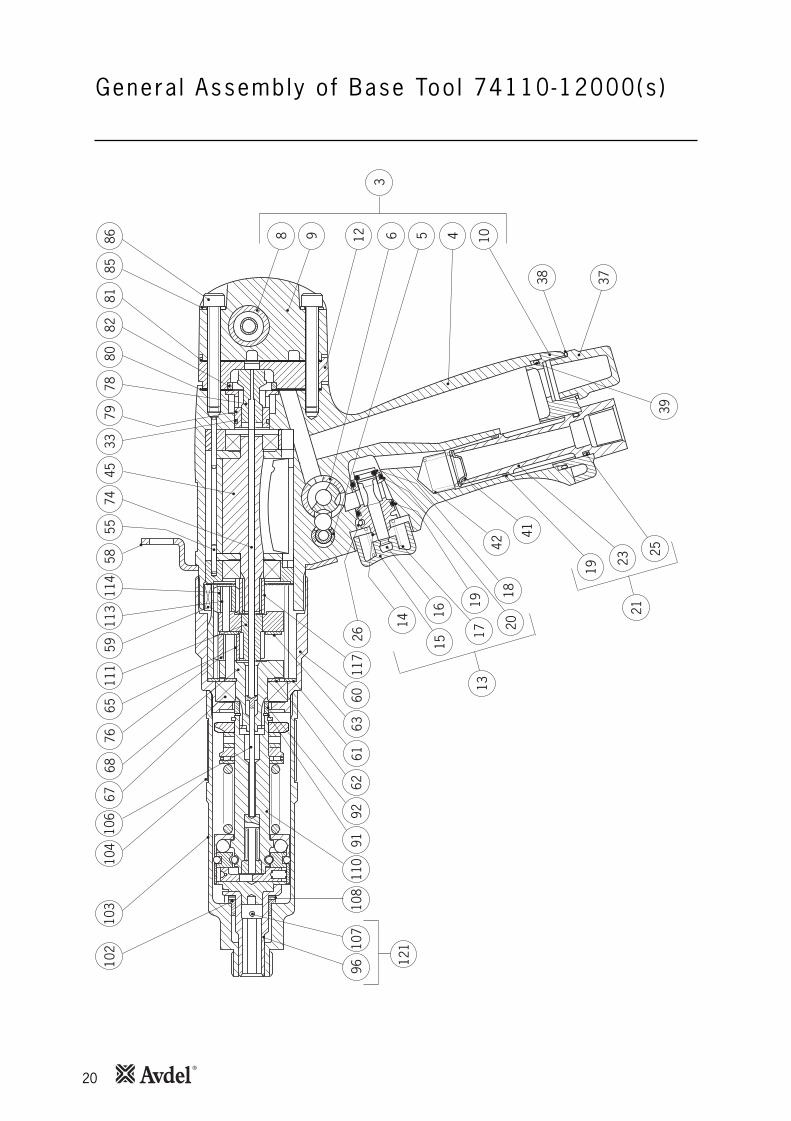
20
Genera l Assembly o f Base Too l 74110-12000(s )10
210
310
410
667
6876
6559
5855
4533
7978
7411
411
311
180
8185
8682
8 9 63
512 4 10
38 37
3925
2321
19
41
4220
18
1719
1516
26
14
6063
6162
9291
108
107
121
9611
011
7
13

21
Par ts L is t for 74110-12000(s )
ITEM
PART
Nº
DES
CR
IPTI
ON
QTY
REC
.SP
ARES
ITEM
PART
Nº
DES
CR
IPTI
ON
QTY
REC
.SP
ARES
74
11
0-1
20
00
PA
RTS
LIS
T
184
100-
1207
4CA
M C
LUTC
H1
284
100-
1207
5LA
TCH
PIN
13
8411
0-12
001
PIST
OL
GRI
P AN
D BU
SH S
A1
484
110-
1200
2PI
STO
L G
RIP
BODY
15
8411
0-12
003
LOCK
ING
BUS
H1
684
110-
1200
4RE
VERS
E VA
LVE
BUSH
17
8410
0-12
076
RETA
ININ
G S
LEEV
E1
884
110-
1200
5VA
LVE
BUSH
19
8411
0-12
006
END
CAP
110
8411
0-12
007
EXHA
UST
CAP
111 12
8411
0-12
008
EXTE
NSI
ON
PIE
CE1
1384
110-
1200
9TR
IGG
ER S
A1
1484
110-
1201
0VA
LVE
BUSH
115
8411
0-12
011
TRIG
GER
BUT
TON
116
8411
0-12
012
VALV
E SP
INDL
E1
1784
110-
1201
3SP
RIN
G1
1884
110-
1201
4'O
' RIN
G1
1984
110-
1201
5'O
' RIN
G1
2084
110-
1201
6'O
' RIN
G1
2184
110-
1201
7AI
R IN
LET
BOLT
SA
122 23
8411
0-12
018
AIR
INLE
T BO
LT1
24 2584
110-
1201
9'O
' RIN
G1
2684
110-
1202
0SP
RIN
G P
IN1
2784
110-
1202
1'O
' RIN
G1
2884
110-
1202
2'O
' RIN
G1
2984
110-
1202
3BA
LL
130
8411
0-12
024
CAP
1
3184
110-
1202
5SP
RIN
G1
3284
110-
1202
6LO
CKIN
G S
PIN
DLE
133
8411
0-12
027
'O' R
ING
334
8411
0-12
028
REVE
RSE
VALV
E1
3584
110-
1202
9RE
TAIN
ING
RIN
G1
3684
100-
1207
7'O
' RIN
G1
237
8411
0-12
030
SILE
NCE
R1
3884
110-
1203
1'O
' RIN
G1
3984
110-
1203
2'O
' RIN
G1
4084
100-
1207
8BA
LL (5
mm
)6
641
8411
0-12
033
AIR
STRA
INER
142
8411
0-12
034
SPRI
NG
143
8410
0-12
079
CUP
BALL
144
8411
0-12
035
'O' R
ING
145
8411
0-12
036
MO
TOR
COM
PLET
E1
4684
110-
1203
7RE
AR B
EARI
NG
HO
USIN
G1
4784
110-
1203
8BE
ARIN
G1
248
8411
0-12
039
REAR
BEA
RIN
G P
LATE
11
4984
110-
1204
0CY
LIN
DER
150
8411
0-12
041
ROTO
R1
5184
110-
1204
2RO
TOR
BLAD
ES5
1052
8411
0-12
043
FRO
NT
BEAR
ING
PLA
TE1
153
8411
0-12
044
FRO
NT
BEAR
ING
HO
USIN
G1
5484
110-
1204
5BE
ARIN
G1
255
8411
0-12
046
SPIR
OL
PIN
156
8410
0-15
001
SPRI
NG
(GRE
EN)
157
8410
0-15
021
SPRI
NG
(YEL
LOW
)1
5884
110-
1204
7SU
SPEN
SIO
N R
ING
159
8411
0-12
048
SQUA
RE K
EY1
6084
110-
1204
9G
EAR
CASE
1

22
Genera l Assembly o f Base Too l 74110-12000(s )10
210
310
410
667
6876
6559
5855
4533
7978
7411
411
311
180
8185
8682
8 9 63
512 4 10
38 37
3925
2321
19
41
4220
18
1719
1516
26
14
6063
6162
9291
108
107
121
9611
011
7
13

23
Par ts L is t for 74110-12000(s )
ITEM
PART
Nº
DES
CR
IPTI
ON
QTY
REC
.SP
ARES
ITEM
PART
Nº
DES
CR
IPTI
ON
QTY
REC
.SP
ARES
74
11
0-1
20
00
PA
RTS
LIS
T
6184
110-
1205
0W
ASHE
R1
6284
110-
1205
1W
ASHE
R1
6384
110-
1205
2W
ASHE
R1
6484
110-
1205
3G
EAR
RIN
G1
6584
110-
1205
4CA
GED
NEE
DLE
ASSy
33
6684
110-
1205
5W
ASHE
R1
6784
100-
1201
5BE
ARIN
G1
168
8411
0-12
056
FIN
AL P
LAN
ET C
ARRI
ER1
6984
110-
1500
0SP
RIN
G (B
LUE)
170
8410
0-12
084
LOCK
WAS
HER
171
8410
0-12
085
ADJU
STIN
G R
ING
172
8410
0-12
086
CIRC
LIP
11
7384
100-
1208
7BA
LL3
374
8411
0-12
057
PUSH
RO
D1
7584
110-
1205
8N
AME
PLAT
E1
7684
110-
1205
9PL
ANET
WHE
EL3
7784
110-
1206
0G
ASKE
T1
7884
110-
1206
1LI
FT V
ALVE
ASS
y1
7984
110-
1206
2VA
LVE
BUSH
180
8411
0-12
063
GAS
KET
181
8411
0-12
064
GAS
KET
182
8411
0-12
065
RIN
G1
8384
110-
1206
6SE
LF A
DHES
IVE
TAPE
184
8410
0-12
088
SPAC
ER1
8584
110-
1206
7LO
CK W
ASHE
R2
8684
110-
1206
8SC
REW
M5
X 40
287
8411
0-12
069
SHUT
TLE
VALV
E1
8884
110-
1207
0CI
RCLI
P2
8984
110-
1207
1CA
P2
9084
110-
1207
2SP
RIN
G1
9184
100-
1201
3CI
RCLI
P1
192
8411
0-12
073
DIST
ANCE
CO
LLAR
193
8410
0-12
091
SPIN
DLE
CLUT
CH A
SSy
194
8410
0-12
090
THRU
ST W
ASHE
R1
9584
100-
1208
9TH
RUST
RAC
E1
196
8410
0-12
001
BIT
HOLD
ER1
9784
100-
1209
2RO
LLER
12
9884
100-
1209
3SP
RIN
G1
9984
100-
1209
4ST
EEL
BALL
1414
100
101
8410
0-12
010
CLUT
CH C
ASE
COM
PLET
E1
102
8411
0-12
074
SPIN
DLE
BEAR
ING
110
384
110-
1207
5CL
UTCH
CAS
E1
104
8411
0-12
076
SPRI
NG
RIN
G1
105
106
8411
0-12
077
PUSH
RO
D1
107
108
8411
0-12
078
SHIM
S1
109
110
8411
0-12
079
CLUT
CH C
OM
PLET
E1
111
8411
0-12
080
PLAN
ET C
ARRI
ER S
A1
112
113
8411
0-12
081
CAG
ED N
EEDL
E AS
Sy3
311
484
110-
1208
2PL
ANET
WHE
EL3
115
116
117
8411
0-12
083
ROTO
R PI
NIO
N1
118
120
8411
0-12
084
LABE
L RE
VERS
E VA
LVE
112
184
100-
1204
5BI
T HO
LDER
SA
1

24
Other symptoms or failures should be reported to your local Avdel authorised distributor or repair centre.
Tool reverses Worn thrust bearing or thrust washers Replace 10before Insert Dirty insert threads Change batch of insertsis placed Worn drive screw Replace 10
Lack of lubrication on drive screw Lubricate drive screw properly (Standard Nutserts only)Thrust spring not fitted Fit thrust spring 10Clutch torque setting too low Adjust to correct setting 15Insufficient pressure/volume of air Check air supply/fittings 8
Tool runs slowly Insufficient air pressure Adjust air pressure at base of handle 85 -6.3 bar maximum.
Incorrect bore of hose Ensure bore of hose is 6.4mm 8minimum
Insufficient air volume Ensure there is no restriction in the 8air supply or connections
Tool not properly lubricated Lubricate as per instructions 12internally
Tool fails to start Tool not properly lubricated Lubricate then depress trigger 12several times
Restricted air pressure/volume Ensure there is no restriction in 8the air supply
Tool runs Push rod too long Replace with one of correct length 19permanently Insufficient air supply Adjust air pressure/volume 5in reverse mode
Tool runs Push rods/needle roller missing Replace where necessary 19permanently Push rod too short Replace 19in forward mode
Inserts not Torque setting too low Adjust to correct setting 15pulling up Insufficient air pressure/volume Adjust air pressure/volume 8
Inserts out of grip Select correct insertLack of lubrication on insert Change batch of insertsLack of lubrication on drive screw Lubricate drive screw correctly(Standard Nutserts only)Insert thread restricted Change InsertsDrive screw thread worn Replace drive screw 10Incorrect insert/drive screw Replace with correct insert/drive 10
screw
continued overleaf
Fau l t D iagnos is
SYMPTOM POSSIBLE CAUSE REMEDY PAGE REFSymptom Poss ib le Cause Remedy Page Ref

25
Other symptoms or failures should be reported to your local Avdel authorised distributor or repair centre.
Standard Dirty Nutserts Clean NutsertsNutserts centres Clutch torque setting too low Adjust to correct setting 15falling out Application thickness below Change to correct Insert
minimum recommended gripOversize hole in application Correct hole size in application
Worn drive Clutch torque setting too high Adjust to correct setting 15screws Drive screw not lubricated Lubricate drive screw regularly
when using Standard NutsertsInserts not lubricated Change batch of insertsTool not held correctly Ensure tool is held square to
applicationIncorrect insert/drive screw threads Replace with correct insert/drive 10
screwRestricted insert threads Change batch of inserts
Fau l t D iagnos is
SYMPTOM POSSIBLE CAUSE REMEDY PAGE REFSymptom Poss ib le Cause Remedy Page Ref

26
Notes

Dec lara t ion o f Conformi ty
We, Avdel UK Limited, Watchmead Industrial Estate, Welwyn Garden City, Herts, AL7 1LY
declare under our sole responsibility that the product:
Model 74110
Serial No. ................................................
to which this declaration relates is in conformity with the following standards:
EN ISO 12100 - parts 1 & 2
BS EN ISO 8662 - part 6 BS EN ISO 11202
BS EN ISO 3744 BS EN 982
ISO EN 792 part 13 - 2000 BS EN 983
following the provisions of the Machine Directive 2006/42/EC
This box contains a power tool which is in conformity with
Machines Directive 2006/42/EC. The ‘Declaration of
Conformity’ is contained within.
Date of issue
A. Seewraj - Product Engineering Manager - Automation Tools

Since 1 936 2010 Since 1922
www.avdel-global.comwww.infastech.com
02.2
011
• ©
201
0 In
fast
ech
Autosert® (equipment), Avbolt ®, Avdel®, Avdelmate®, Avdel TX2000®, Avdelok®, Avex®, Avibulb®, Avinox®, Avinut™, Avlug®, Avmatic®, Avplas®,Avseal®, Avsert®, Avtainer®, Avtronic®, Briv®, Bulbex®, Chobert®, Eurosert®, Fastriv®, Finsert®, Genesis®, Grovit®, Hemlok®, Hexsert®, Holding your world together®, Hydra®, Interlock®, Klamp-Tite®, Klamptite KTR®, Kvex®, Maxlok®, Monobolt®, Monobulb ®, Neobolt®, Nutsert®, Nutsert SQ®, Portariv®, Rivmatic®, Rivscrew®, Speed Fastening®, Squaresert®, Stavex®, Supersert®, Thin Sheet Nutsert®, Titan®, T-Lok®, TLR®, TSN®, TX2000®, Versa-Nut®, Viking® and Viking 360® are trademarks of Avdel UK Limited. Infastech™ and Our Technology, Your Success™ are trademarks of Infastech Intellectual Properties Pte Ltd. The names and logos of other companies mentioned herein may be trademarks of their respective owners. This document is for informational purposes only. Infastech makes no warranties, expressed or implied, in this document. Data shown is subject to change without prior notice as a result of continuous product development and improvement policy. Your local Avdel representative is at your disposal should you need to confirm latest information.
AUSTRALIAInfastech (Australia) Pty Ltd.891 Wellington RoadRowvilleVictoria 3178Tel: +61 3 9765 6400Fax: +61 3 9765 [email protected]
CANADAAvdel Canada Limited1030 Lorimar DriveMississaugaOntario L5S 1R8Tel: +1 905 364 0664Fax: +1 905 364 [email protected]
CHINAInfastech (China) Ltd.RM 1708, 17/F., Nanyang Plaza,57 Hung To Rd., Kwun TongHong KongTel: +852 2950 0631Fax: +852 2950 [email protected]
FRANCEAvdel France S.A.S.33 bis, rue des ArdennesBP4 75921 Paris Cedex 19Tel: +33 (0) 1 4040 8000Fax: +33 (0) 1 4208 [email protected]
GERMANYAvdel Deutschland GmbHKlusriede 2430851 LangenhagenTel: +49 (0) 511 7288 0Fax: +49 (0) 511 7288 [email protected]
INDIAInfastech Fastening Technologies India Private LimitedPlot No OZ-14, Hi Tech SEZ,SIPCOT Industrial Growth Center,Oragadam, Sriperumbudur Taluk, Kanchipuram District,602105 TamilnaduTel: +91 44 4711 8001Fax: +91 44 4711 [email protected]
ITALYAvdel Italia S.r.l.Viale Lombardia 51/5320047 Brugherio (MI)Tel: +39 039 289911Fax: +39 039 [email protected]
JAPANInfastech Kabushiki KaishaCenter Minami SKY, 3-1 Chigasaki-Chuo, Tsuzuki-ku,Yokohama-city, Kanagawa PrefectureJapan 224-0032Tel: +81 45 947 1200Fax: +81 45 947 [email protected]
MALAYSIAInfastech (Malaysia) Sdn BhdLot 63, Persiaran Bunga Tanjung 1,Senawang Industrial Park70400 SerembanNegeri SembilanTel: +606 676 7168Fax: +606 676 [email protected]
SINGAPOREInfastech (Singapore) Pte Ltd. 31 Kaki Bukit Road 3#05-03/06 TechlinkSingapore, 417818Tel: +65 6372 5653Fax: +65 6744 [email protected]
SOUTH KOREAInfastech (Korea) Ltd.212-4, Suyang-Ri,Silchon-Eup, Kwangju-City,Kyunggi-Do, Korea, 464-874Tel: +82 31 798 6340Fax: +82 31 798 [email protected]
SPAIN Avdel Spain S.A.C/ Puerto de la Morcuera, 14Poligono Industrial Prado OveraCtra. de Toledo, km 7,828919 Leganés (Madrid)Tel: +34 91 3416767Fax: +34 91 [email protected]
TAIWANInfastech/Tri-Star LimitedNo 269-7, Baodong Rd, Guanmiao Township,71841 Tainan County,Taiwan, R.O.CTel: +886 6 596 5798 (ext 201)Fax: +886 6 596 [email protected]
UNITED KINGDOMAvdel UK LimitedPacific House2 SwiftfieldsWatchmead Industrial EstateWelwyn Garden CityHertfordshire AL7 1LYTel: +44 (0) 1707 292000Fax: +44 (0) 1707 [email protected]
USAAvdel USA LLC614 NC Highway 200 SouthStanfield, North Carolina 28163Tel: +1 704 888 7100Fax: +1 704 888 [email protected]
Manual No. Issue Change Note No. Date
AA 03/046
AB 07/176
AC 11/07207900-00794