sensor de precion qtb
TRANSCRIPT
7/27/2019 Sensor de Precion QTB
http://slidepdf.com/reader/full/sensor-de-precion-qtb 1/24
TI415P/00/en
Technical Information
Cerabar T PMC131, PMP131, PMP135
Pressure Transducer
With ceramic and metal sensorsFor absolute pressure and gauge pressure measurement up to 400 bar
Extremely stable, overload-resistant and reliable
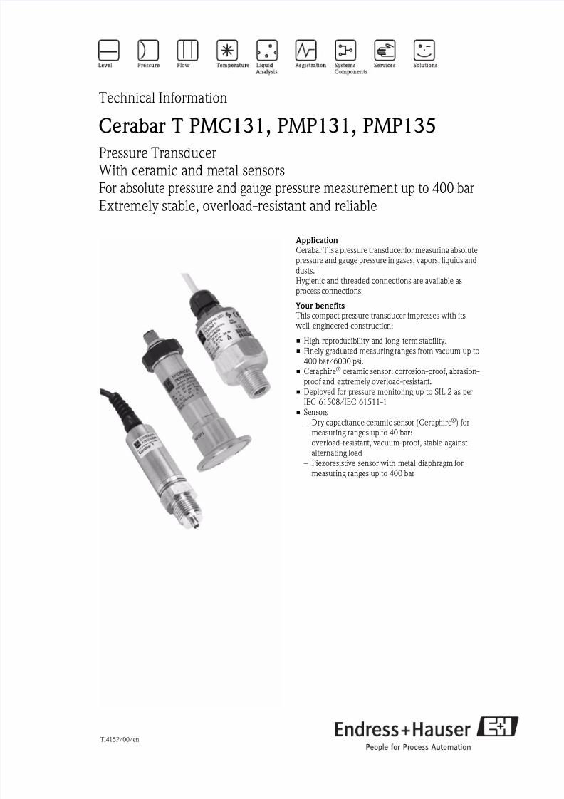
ApplicationCerabar T is a pressure transducer for measuring absolute
pressure and gauge pressure in gases, vapors, liquids and
dusts.
Hygienic and threaded connections are available as
process connections.
Your benefitsThis compact pressure transducer impresses with its
well-engineered construction:
• High reproducibility and long-term stability.
• Finely graduated measuring ranges from vacuum up to
400 bar/6000 psi.
• Ceraphire® ceramic sensor: corrosion-proof, abrasion-
proof and extremely overload-resistant.
• Deployed for pressure monitoring up to SIL 2 as per
IEC 61508/IEC 61511-1
• Sensors– Dry capacitance ceramic sensor (Ceraphire®) for
measuring ranges up to 40 bar:
overload-resistant, vacuum-proof, stable against
alternating load
– Piezoresistive sensor with metal diaphragm for
measuring ranges up to 400 bar
7/27/2019 Sensor de Precion QTB
http://slidepdf.com/reader/full/sensor-de-precion-qtb 2/24
Cerabar T
2 Endress+Hauser
Table of contents
Function and system design. . . . . . . . . . . . . . . . . . . . . 3
Device selection . . . . . . . . . . . . . . . . . . . . . . . . . . . . . . . . . . . . . . 3
Measuring principle . . . . . . . . . . . . . . . . . . . . . . . . . . . . . . . . . . . 3Measuring system . . . . . . . . . . . . . . . . . . . . . . . . . . . . . . . . . . . . . 4
Input . . . . . . . . . . . . . . . . . . . . . . . . . . . . . . . . . . . . . . 4
Measured variable . . . . . . . . . . . . . . . . . . . . . . . . . . . . . . . . . . . . 4
Measuring range . . . . . . . . . . . . . . . . . . . . . . . . . . . . . . . . . . . . . 4
Output . . . . . . . . . . . . . . . . . . . . . . . . . . . . . . . . . . . . . 4
Output signal . . . . . . . . . . . . . . . . . . . . . . . . . . . . . . . . . . . . . . . . 4
Load . . . . . . . . . . . . . . . . . . . . . . . . . . . . . . . . . . . . . . . . . . . . . . 4
Output signal . . . . . . . . . . . . . . . . . . . . . . . . . . . . . . . . . . . . . . . . 4
Output current . . . . . . . . . . . . . . . . . . . . . . . . . . . . . . . . . . . . . . . 4
Power . . . . . . . . . . . . . . . . . . . . . . . . . . . . . . . . . . . . . . . . . . . . . 5Switch frequency . . . . . . . . . . . . . . . . . . . . . . . . . . . . . . . . . . . . . 5
Input PLC . . . . . . . . . . . . . . . . . . . . . . . . . . . . . . . . . . . . . . . . . . 5
Inductive loads . . . . . . . . . . . . . . . . . . . . . . . . . . . . . . . . . . . . . . . 5
Power supply. . . . . . . . . . . . . . . . . . . . . . . . . . . . . . . . 5
PMC131 . . . . . . . . . . . . . . . . . . . . . . . . . . . . . . . . . . . . . . . . . . . 5
PMP131 and PMP135 . . . . . . . . . . . . . . . . . . . . . . . . . . . . . . . . . 6
PMP131 . . . . . . . . . . . . . . . . . . . . . . . . . . . . . . . . . . . . . . . . . . . 7
Supply voltage . . . . . . . . . . . . . . . . . . . . . . . . . . . . . . . . . . . . . . . 7
Residual ripple . . . . . . . . . . . . . . . . . . . . . . . . . . . . . . . . . . . . . . . 7
Cable entry . . . . . . . . . . . . . . . . . . . . . . . . . . . . . . . . . . . . . . . . . 7
Performance characteristics. . . . . . . . . . . . . . . . . . . . . 8Reference operating
conditions . . . . . . . . . . . . . . . . . . . . . . . . . . . . . . . . . . . . . . . . . . 8
Long-term stability . . . . . . . . . . . . . . . . . . . . . . . . . . . . . . . . . . . . 8
Maximum measured error
of analog output
(under reference operating conditions) . . . . . . . . . . . . . . . . . . . . . 8
Switch point . . . . . . . . . . . . . . . . . . . . . . . . . . . . . . . . . . . . . . . . . 8
Rise time (T90) . . . . . . . . . . . . . . . . . . . . . . . . . . . . . . . . . . . . . . 8
Settling time . . . . . . . . . . . . . . . . . . . . . . . . . . . . . . . . . . . . . . . . . 8
Thermal change of the lower range value and the span . . . . . . . . . 9
Temperature coefficient (TK) for lower range value and span . . . . . 9
Operating conditions (Installation instructions). . . . . . 9Orientation . . . . . . . . . . . . . . . . . . . . . . . . . . . . . . . . . . . . . . . . . 9
Installation instructions . . . . . . . . . . . . . . . . . . . . . . . . . . . . . . . . . 9
Location dependence . . . . . . . . . . . . . . . . . . . . . . . . . . . . . . . . . . 9
Operating conditions (environment) . . . . . . . . . . . . . 10
Ambient temperature range . . . . . . . . . . . . . . . . . . . . . . . . . . . . 10
Storage temperature range . . . . . . . . . . . . . . . . . . . . . . . . . . . . . 10
Climate class . . . . . . . . . . . . . . . . . . . . . . . . . . . . . . . . . . . . . . . 10
Degree of protection . . . . . . . . . . . . . . . . . . . . . . . . . . . . . . . . . . 10
Vibration resistance . . . . . . . . . . . . . . . . . . . . . . . . . . . . . . . . . . 10
Electromagnetic compatibility . . . . . . . . . . . . . . . . . . . . . . . . . . . 10
Operating conditions (process) . . . . . . . . . . . . . . . . . 11
Process temperature range . . . . . . . . . . . . . . . . . . . . . . . . . . . . . 11
Overload resistance . . . . . . . . . . . . . . . . . . . . . . . . . . . . . . . . . . 11 Vacuum resistance . . . . . . . . . . . . . . . . . . . . . . . . . . . . . . . . . . . 11
Pressure specifications . . . . . . . . . . . . . . . . . . . . . . . . . . . . . . . . 11
Mechanical construction . . . . . . . . . . . . . . . . . . . . . . 12
PMC131 . . . . . . . . . . . . . . . . . . . . . . . . . . . . . . . . . . . . . . . . . . 12
PMP131 and PMP135 . . . . . . . . . . . . . . . . . . . . . . . . . . . . . . . . 13
PMP131 . . . . . . . . . . . . . . . . . . . . . . . . . . . . . . . . . . . . . . . . . . 13
PMP135 . . . . . . . . . . . . . . . . . . . . . . . . . . . . . . . . . . . . . . . . . . 14
Weights . . . . . . . . . . . . . . . . . . . . . . . . . . . . . . . . . . . . . . . . . . . 15
Material . . . . . . . . . . . . . . . . . . . . . . . . . . . . . . . . . . . . . . . . . . . 15
Operating elements . . . . . . . . . . . . . . . . . . . . . . . . . . 15
Operating elements . . . . . . . . . . . . . . . . . . . . . . . . . . . . . . . . . . 15
Certificates and approvals . . . . . . . . . . . . . . . . . . . . . 17
CE mark . . . . . . . . . . . . . . . . . . . . . . . . . . . . . . . . . . . . . . . . . . 17
Ex approvals . . . . . . . . . . . . . . . . . . . . . . . . . . . . . . . . . . . . . . 17
Pressure Equipment Directive (PED) . . . . . . . . . . . . . . . . . . . . . 17
Functional safety SIL 2 . . . . . . . . . . . . . . . . . . . . . . . . . . . . . . . . 17
Suitability for hygenic processes . . . . . . . . . . . . . . . . . . . . . . . . . 17
TSE Certificate of Suitability . . . . . . . . . . . . . . . . . . . . . . . . . . . . 17
Standards and guidelines . . . . . . . . . . . . . . . . . . . . . . . . . . . . . . 17
Registered trademarks . . . . . . . . . . . . . . . . . . . . . . . . . . . . . . . . 17
Ordering information. . . . . . . . . . . . . . . . . . . . . . . . . 18PMC131 . . . . . . . . . . . . . . . . . . . . . . . . . . . . . . . . . . . . . . . . . . 18
PMC131 (continued) . . . . . . . . . . . . . . . . . . . . . . . . . . . . . . . . . 19
PMP131 . . . . . . . . . . . . . . . . . . . . . . . . . . . . . . . . . . . . . . . . . . 20
PMP131 (continued) . . . . . . . . . . . . . . . . . . . . . . . . . . . . . . . . . 21
PMP135 . . . . . . . . . . . . . . . . . . . . . . . . . . . . . . . . . . . . . . . . . . 22
Accessories . . . . . . . . . . . . . . . . . . . . . . . . . . . . . . . . 23
Welding neck with
sealing taper . . . . . . . . . . . . . . . . . . . . . . . . . . . . . . . . . . . . . . . 23
Welding neck with
sealing surface . . . . . . . . . . . . . . . . . . . . . . . . . . . . . . . . . . . . . . 23
Plug-in jack . . . . . . . . . . . . . . . . . . . . . . . . . . . . . . . . . . . . . . . . 23
Plug-on display PHX20/PHX21 . . . . . . . . . . . . . . . . . . . . . . . . . . . . . . . . . . . . . 23
Documentation . . . . . . . . . . . . . . . . . . . . . . . . . . . . . 24
Field of Activities . . . . . . . . . . . . . . . . . . . . . . . . . . . . . . . . . . . . 24
Technical Information . . . . . . . . . . . . . . . . . . . . . . . . . . . . . . . . 24
Operating Instructions . . . . . . . . . . . . . . . . . . . . . . . . . . . . . . . . 24
Functional Safety Manual (SIL) . . . . . . . . . . . . . . . . . . . . . . . . . 24
Safety Instructions . . . . . . . . . . . . . . . . . . . . . . . . . . . . . . . . . . . 24
7/27/2019 Sensor de Precion QTB
http://slidepdf.com/reader/full/sensor-de-precion-qtb 3/24
Cerabar T
Endress+Hauser 3
Function and system design
Device selection
Measuring principle PMC131
The measuring pressure causes a slight deflection of the ceramic diaphragm of the sensor. The pressure-
proportional change in capacitance is measured at the electrodes of the ceramic sensor. The ceramic sensor isa dry sensor, i.e. no fill fluid is required for the pressure transfer. This makes the sensor completely suitable for
vacuums. Extremely high stability, comparable with the material Alloy, is achieved by using ultrapure
Ceraphire® as the ceramic.
PMP131 and PMP135 with analog output
The process pressure acting upon the metallic separating diaphragm of the sensor is transmitted to a resistance
bridge via a fluid. The pressure-proportional change of the bridge output voltage is measured and processed
further.
PMP131 and PMP135 with switch output
The process pressure acting upon the metallic separating diaphragm of the sensor is transmitted to a resistance
bridge via a fluid. A differential amplifier creates a standard signal from the pressure-proportional change in
output voltage of the bridge. A comparator with an adjustable hysteresis compares this signal with the pre-set switch point and then activates the transistor output.
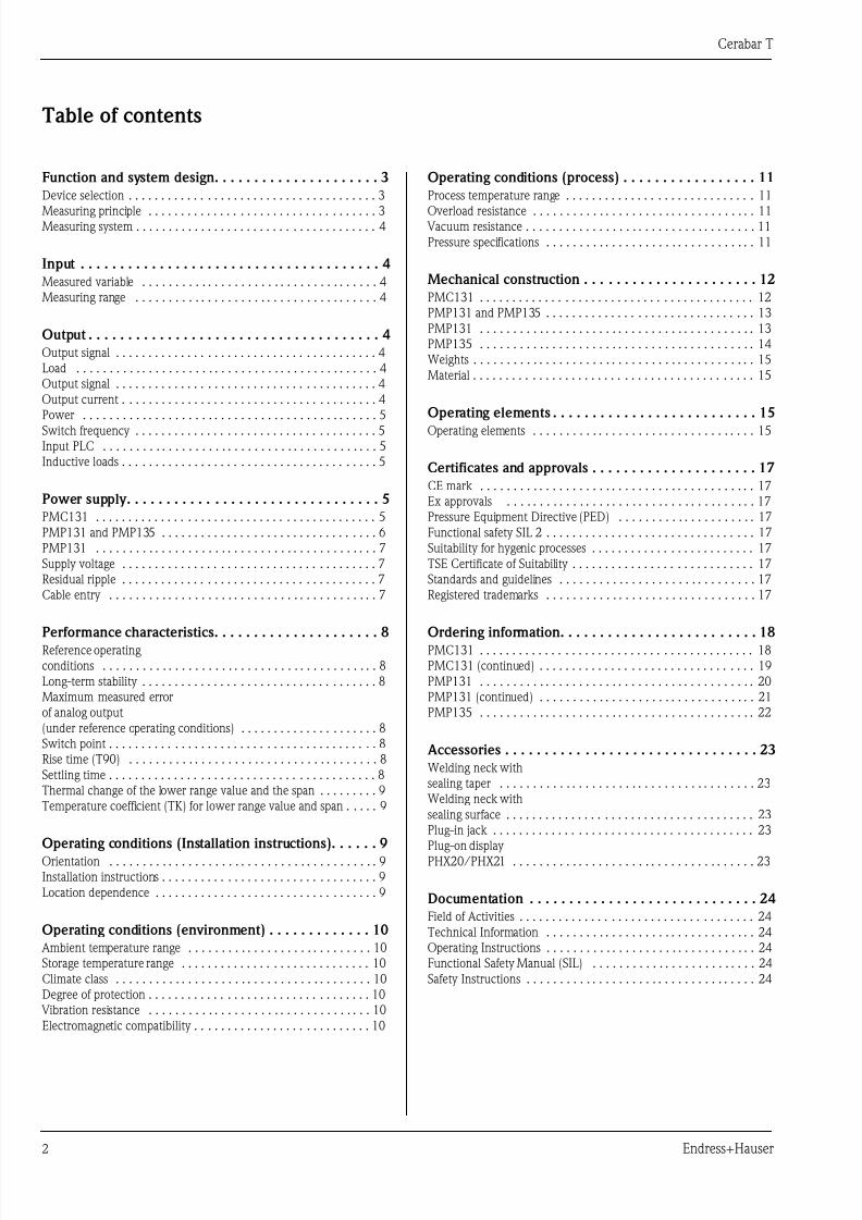
Cerabar T PMC131 PMP131 PMP135
P01-PMC131xx-14-xx-xx-xx-000 P01-PMP131xx-14-xx-xx-xx-000 P01-PMP135xx-14-xx-xx-xx-000
With capacitive measuring cell and ceramic measuring
diaphragm (Ceraphire®)
With piezoresistivemeasuring cell and metallic
measuring diaphragm
With piezoresistive measuring celland metallic measuring
diaphragm for hygienic
applications
Field of
application
Absolute pressure and gauge
pressure
Absolute pressure and gauge
pressure
Absolute pressure and gauge pressure
in hygienic processes
Output Current output 4 to 20 mA – Current output 4 to 20 mA
– Voltage output 0 to 10 V
– Switch output PNP
– 4 to 20 mA
– Switch output PNP
Process
connection
Thread:
– G ½
– ½ MNPT and ¼ FNPT
– G ½, bore 11 mm
Thread:
– G ½
– ½ MNPT and ¼ FNPT
– ½ MNPT, bore 4 mm
– G ¼– ¼ MNPT, bore 3.5 mm
– M 20 x 1.5
Hygiene:
– Clamp DN 22 (¾")
– Tri-Clamp DN 25 to 38 (1" to 1½")
– Tri-Clamp DN 40 to 51 (2")
– G 1– SMS 1½"
Measuring
range
–1 to 0 bar/–100 to 0 kPa
up to
0 to 40 bar/0 to 4 MPa
0 to 1 bar/0 to 100 kPa
up to
0 to 400 bar/0 to 40 MPa
0 to 1 bar/0 to 100 kPa
up to
0 to 40 bar/0 to 4 MPa
Process
temperature
–20 to +100 °C –25 °C to +70 °C –25 to +100 °C
(+135 °C for max. 1 hour)
ENDRESS+HAUSERCERABAR T
ENDRESS+HAUSER
CERABART
ENDRESS+HAUSER
CERABART
7/27/2019 Sensor de Precion QTB
http://slidepdf.com/reader/full/sensor-de-precion-qtb 4/24
Cerabar T
4 Endress+Hauser
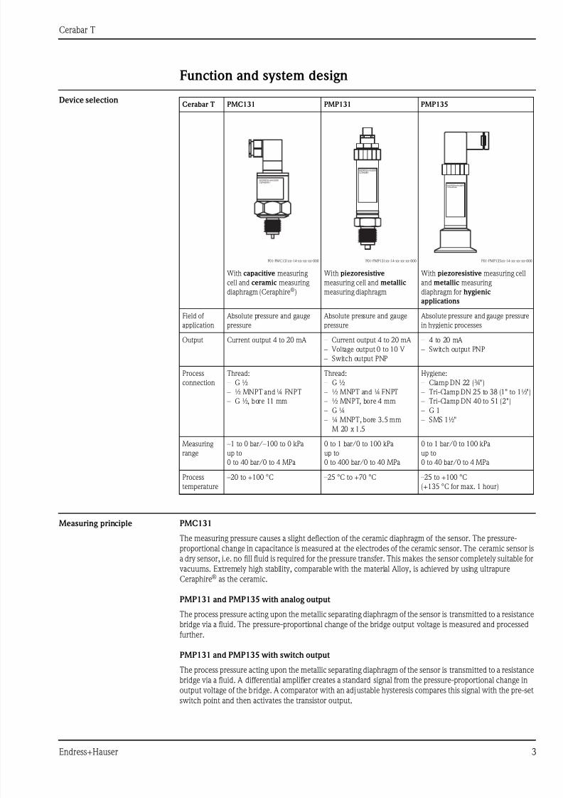
Measuring system
P01-PMx13xxx-14-xx-xx-xx-002
1 PMP131, PMP135: current output with transmitter power supply unit, e.g. RN 221N from Endress+Hauser
2 PMP131, PMP135: switch output with load, e.g. PLC, DCS, relay
3 PMC131: voltage output with transmitter power supply unit, e.g. RIA452 from Endress+Hauser
4 PMC131: current output with transmitter power supply unit, e.g. RN 221N from Endress+Hauser
Input Measured variable Absolute pressure or gauge pressure
Measuring range up to 400 bar/6000 psi, see Page 18, "Ordering information" section
Output
Analog output (PMC131, PMP131, PMP135)
Output signal 4 to 20 mA
Load PMC131
R Lmax [Ω] ≤ (US – 1 V) / 0.02 A
PMP131 and PMP135 (current output)
R Lmax [Ω] ≤ (US – 12 V) / 0.02 A (R Lmax: Maximum load resistance, US: Supply voltage)
PMP131 (voltage output)
Load resistance R Lmax ≥5 k Ω, current consumption ≤6 mA
Switch output (PMP131, PMP135)
Output signal PNP switch output (positive voltage signal), rate depends on power supply voltage
Output current • Switch status ON: Ia ≤ 500 mA
• Switch status OFF: Ia ≤ 1 mA
4...20 mA
0...10 V 4...20 mA
➩
➩ ➩
➩
p
pp
p
– –
–
++
+
+
1 2
3 4
R
7/27/2019 Sensor de Precion QTB
http://slidepdf.com/reader/full/sensor-de-precion-qtb 5/24
Cerabar T
Endress+Hauser 5
Power max. 6 W
Switch frequency max. 10 Hz
Input PLC • Input resistance R i ≤ 2 k Ω
• Input current Ii ≥ 10 mA
Inductive loads To prevent electrical interference, only operate an inductive load (relays, contactors, solenoid valves) when
directly connected to a protective circuit (free-wheeling diode or capacitor).
Power supply
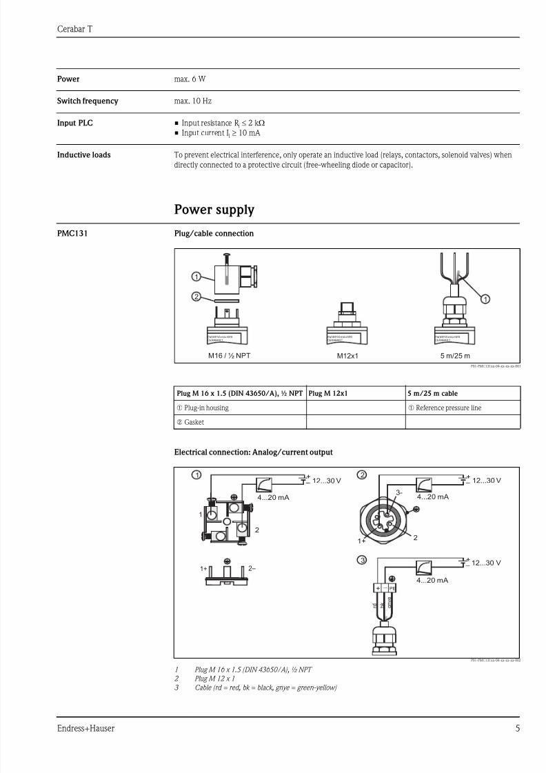
PMC131 Plug/cable connection
P01-PMC131xx-04-xx-xx-xx-001
Electrical connection: Analog/current output
P01-PMC131xx-04-xx-xx-xx-002
1 Plug M 16 x 1.5 (DIN 43650/A), ½ NPT
2 Plug M 12 x 1
3 Cable (rd = red, bk = black, gnye = green-yellow)
Plug M 16 x 1.5 (DIN 43650/A), ½ NPT Plug M 12x1 5 m/25 m cable
➀ Plug-in housing ➀ Reference pressure line
➁ Gasket
M16 / ½ NPT M12x1 5 m/25 m
1
2
ENDRESS+HAUSERCERABAR T
ENDRESS+HAUSERCERABAR T
ENDRESS+HAUSERCERABAR T
1
– –
–
+ +
+
+ PE –
r d b k
g n y e
2
1
1+ 2 –12...30 V
12...30 V12...30 V
4...20 mA4...20 mA
4...20 mA
1 2
3
1+2
3-
7/27/2019 Sensor de Precion QTB
http://slidepdf.com/reader/full/sensor-de-precion-qtb 6/24
Cerabar T
6 Endress+Hauser
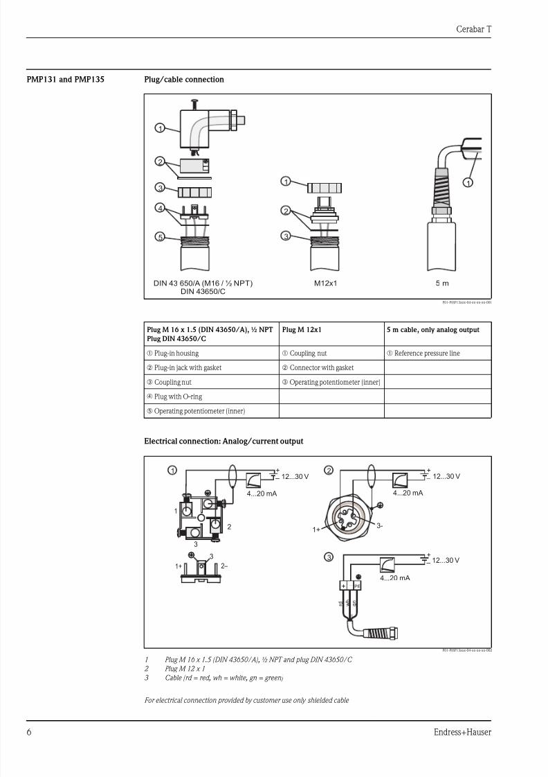
PMP131 and PMP135 Plug/cable connection
P01-PMP13xxx-04-xx-xx-xx-001
Electrical connection: Analog/current output
P01-PMP13xxx-04-xx-xx-xx-002
1 Plug M 16 x 1.5 (DIN 43650/A), ½ NPT and plug DIN 43650/C
2 Plug M 12 x 13 Cable (rd = red, wh = white, gn = green)
For electrical connection provided by customer use only shielded cable
Plug M 16 x 1.5 (DIN 43650/A), ½ NPT
Plug DIN 43650/C
Plug M 12x1 5 m cable, only analog output
➀ Plug-in housing ➀ Coupling nut ➀ Reference pressure line
➁ Plug-in jack with gasket ➁ Connector with gasket
➂ Coupling nut ➂ Operating potentiometer (inner)
➃ Plug with O-ring
➄ Operating potentiometer (inner)
DIN 43 650/ A (M16 / ½ NPT)DIN 43650/C
M12x1 5 m
1
1 1
2
2
3
3
4
5
– –
–
+ +
+
+ PE –
r d w h
g n
3
3
2
1
1+ 2 –12...30 V
12...30 V12...30 V
4...20 mA4...20 mA
4...20 mA
1 2
3
1+3-

7/27/2019 Sensor de Precion QTB
http://slidepdf.com/reader/full/sensor-de-precion-qtb 7/24
Cerabar T
Endress+Hauser 7
Electrical connection (switch output)
P01-PMP13xxx-04-xx-xx-xx-003
1 Plug M 16 x 1.5 (DIN 43650/A), ½ NPT
2 Plug M 12 x 1
R External load, e.g. relay, programmable logic controller, distributed control system
For electrical connection provided by customer use only shielded cable
PMP131 Electrical connection: Analog-/voltage output
P01-PMP131xx-04-xx-xx-xx-001
1 Plug M 16 x 1,5 (DIN 43650/A), ½ NPT and plug DIN 43 650/C
2 Plug M 12 x 1
3 Cable (rd = red, wh = white, gn = green)
For electrical connection provided by customer use only shielded cable
Supply voltage PMC131
11 to 30 V DC
PMP131 and PMP135 (current output, 2-wire version)
• For non-hazardous areas: 12 to 30 V DC• Ex i: no-load voltage ≤ 26 V DC, short-circuit current ≤ 100 mA, power consumption ≤ 0.8 W
PMP131 (voltage output, 3-wire version)
• 15...30 V DC
PMP131 and PMP135 (switch output)
• 18 to 32 V DC, current consumption without load < 20 mA, with reverse polarity protection
Residual ripple • Analog output: max. 5 % of supply voltage
• Switch output: max. 10 % of supply voltage
Cable entry → See Page 18, "Ordering information" section.
– –
+ +
2 –1+
3+
R
R
18...32 V18...32 V
3
2
1
1 2
1+
2-3
– – –
+ + +
+ + PE –
r d b k
w h
g n
3+
3-
2-
1+
1+
2+
15...30 V
15...30 V15...30 V
0...10 V0...10 V 0...10 V1 2 3
7/27/2019 Sensor de Precion QTB
http://slidepdf.com/reader/full/sensor-de-precion-qtb 8/24
Cerabar T
8 Endress+Hauser
Performance characteristics
Reference operating
conditions
as per DIN IEC 60770, TU = 25 °C
Long-term stability ≤ 0.15 % of URL per year
Maximum measured error
of analog output
(under reference operating
conditions)
The measured error comprises the non-linearity including hysteresis and non-reproducibility in accordance
with the limit point method as per IEC 60770.
PMC131
• ≤ 0.5 % of (URL - LRL) x TD1)
PMP131 and PMP135
• ≤ 0.5 % of URL
Switch point PMP131 and PMP135
• Deviation: ≤ 1 % of URL
• Non-reproducibility: ≤ 0.5 % of URL
Rise time (T90) PMC131
20 ms
Settling time PMP131 and PMP135
2 to 5 ms
1) extended specifications apply to customer-specific measuring ranges
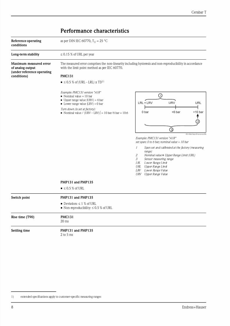
Example: PMC131 version "A1R"
• Nominal value = 10 bar
• Upper range value (URV) = 6 bar
• Lower range value (LRV) = 0 bar
Turn down (is set at factory):
• Nominal value / (URV – LRV)⏐= 10 bar/6 bar = 10:6
P01-PMx13xxx-05-xx-xx-xx-001
Example: PMC131 version "A1R"
set span: 0 to 6 bar; nominal value = 10 bar
1 Span set and calibrated at the factory (measuring
range)
2 Nominal value i Upper Range Limit (URL)
3 Sensor measuring range
LRL Lower Range Limit
URL Upper Range Limit
LRV Lower Range Value
URV Upper Range Value
0 bar +10 bar
URLURVLRL = LRV
+6 bar
2
1
3
7/27/2019 Sensor de Precion QTB
http://slidepdf.com/reader/full/sensor-de-precion-qtb 9/24
Cerabar T
Endress+Hauser 9
Thermal change of the lower
range value and the span
PMC1312)
Zero output, −20 to +85 °C:
• typically 1.5 % of URL
Output span, −20 to +85 °C:
• Nominal value 0.4 to 40 bar: typically 0.8 % of URL
• Nominal value 0.1bar: typically 1.0 % of URL
Temperature coefficient (TK )
for lower range value and span
PMP131 and PMP135 (analog output)
Zero output:
• typically: 0.2 % of URL/10 K
• max.: 0.5 % of URL/10 K
• Nominal value ≤ 6 bar: by 0.1 % of URL/10 K higher
Output signal:
• typically: 0.2 % of URL/10 K
• max.: 0.5 % of URL/10 K
PMP131 and PMP135 (switch output)
Switch point:
• typically: 0.2 % of URL/10 K
• max.: 0.5 % of URL/10 K
Operating conditions (Installation instructions)
Orientation anywhere
Installation instructions PMP131
Process connection G 1/2 flush-mounted, max. torque 40 Nm
Location dependence PMC131
without influence
PMP131 and PMP135
Position-dependent zero point shift can be corrected by potentiometer setting, see also Page 16.
2) for customer-specific measuring-ranges: values are doubled
7/27/2019 Sensor de Precion QTB
http://slidepdf.com/reader/full/sensor-de-precion-qtb 10/24
Cerabar T
10 Endress+Hauser
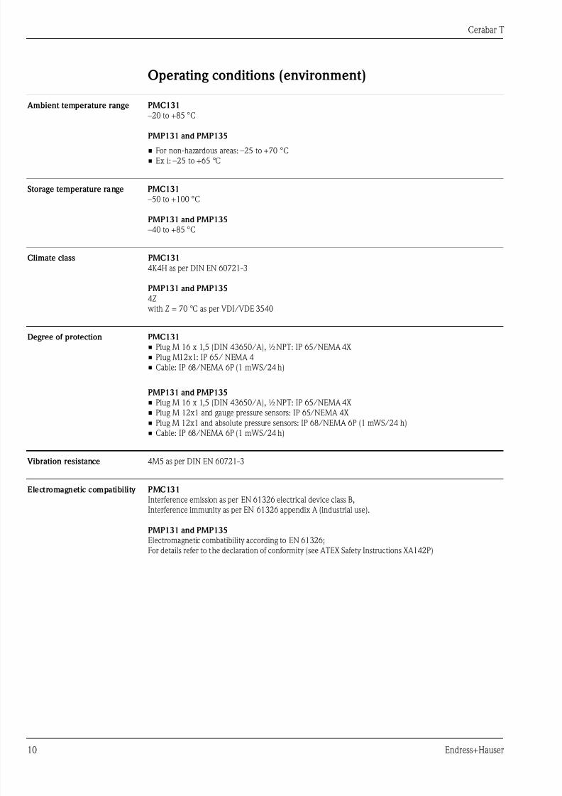
Operating conditions (environment)
Ambient temperature range PMC131
–20 to +85 °C
PMP131 and PMP135
• For non-hazardous areas: –25 to +70 °C
• Ex i: –25 to +65 °C
Storage temperature range PMC131
–50 to +100 °C
PMP131 and PMP135
–40 to +85 °C
Climate class PMC131
4K4H as per DIN EN 60721-3
PMP131 and PMP135
4Z
with Z = 70 °C as per VDI/VDE 3540
Degree of protection PMC131
• Plug M 16 x 1,5 (DIN 43650/A), ½ NPT: IP 65/NEMA 4X
• Plug M12x1: IP 65/ NEMA 4
• Cable: IP 68/NEMA 6P (1 mWS/24 h)
PMP131 and PMP135
• Plug M 16 x 1,5 (DIN 43650/A), ½ NPT: IP 65/NEMA 4X
• Plug M 12x1 and gauge pressure sensors: IP 65/NEMA 4X• Plug M 12x1 and absolute pressure sensors: IP 68/NEMA 6P (1 mWS/24 h)
• Cable: IP 68/NEMA 6P (1 mWS/24 h)
Vibration resistance 4M5 as per DIN EN 60721-3
Electromagnetic compatibility PMC131
Interference emission as per EN 61326 electrical device class B,
Interference immunity as per EN 61326 appendix A (industrial use).
PMP131 and PMP135
Electromagnetic combatibility according to EN 61326;
For details refer to the declaration of conformity (see ATEX Safety Instructions XA142P)
7/27/2019 Sensor de Precion QTB
http://slidepdf.com/reader/full/sensor-de-precion-qtb 11/24
Cerabar T
Endress+Hauser 11
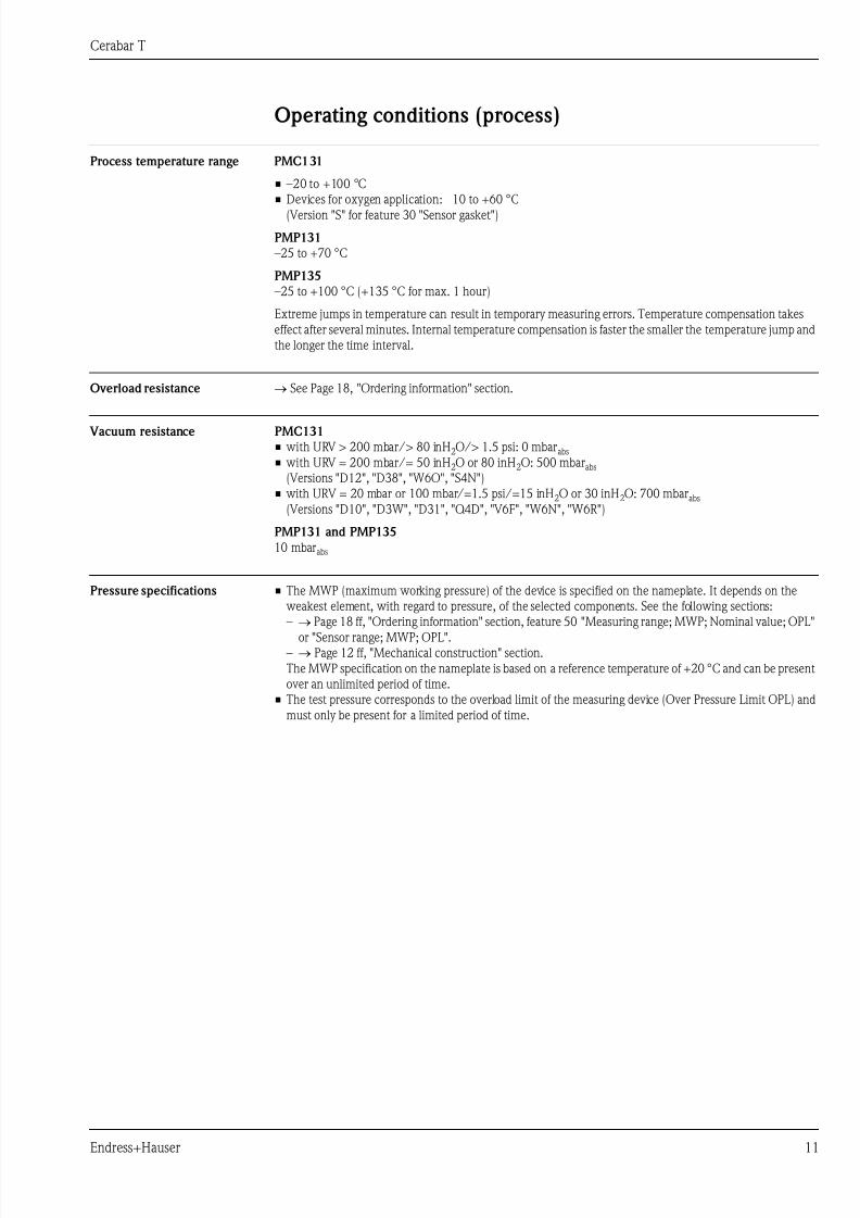
Operating conditions (process)
Process temperature range PMC131
• –20 to +100 °C
• Devices for oxygen application: −10 to +60 °C
(Version "S" for feature 30 "Sensor gasket")
PMP131
–25 to +70 °C
PMP135
–25 to +100 °C (+135 °C for max. 1 hour)
Extreme jumps in temperature can result in temporary measuring errors. Temperature compensation takes
effect after several minutes. Internal temperature compensation is faster the smaller the temperature jump and
the longer the time interval.
Overload resistance → See Page 18, "Ordering information" section.
Vacuum resistance PMC131
• with URV > 200 mbar/> 80 inH2O/> 1.5 psi: 0 mbarabs
• with URV = 200 mbar/= 50 inH2O or 80 inH2O: 500 mbarabs
(Versions "D12", "D38", "W6O", "S4N")
• with URV = 20 mbar or 100 mbar/=1.5 psi/=15 inH2O or 30 inH2O: 700 mbarabs
(Versions "D10", "D3W", "D31", "Q4D", "V6F", "W6N", "W6R")
PMP131 and PMP135
10 mbarabs
Pressure specifications • The MWP (maximum working pressure) of the device is specified on the nameplate. It depends on the
weakest element, with regard to pressure, of the selected components. See the following sections:
– → Page 18 ff, "Ordering information" section, feature 50 "Measuring range; MWP; Nominal value; OPL"
or "Sensor range; MWP; OPL".
– → Page 12 ff, "Mechanical construction" section.
The MWP specification on the nameplate is based on a reference temperature of +20 °C and can be present
over an unlimited period of time.
• The test pressure corresponds to the overload limit of the measuring device (Over Pressure Limit OPL) and
must only be present for a limited period of time.
7/27/2019 Sensor de Precion QTB
http://slidepdf.com/reader/full/sensor-de-precion-qtb 12/24
Cerabar T
12 Endress+Hauser
Mechanical construction
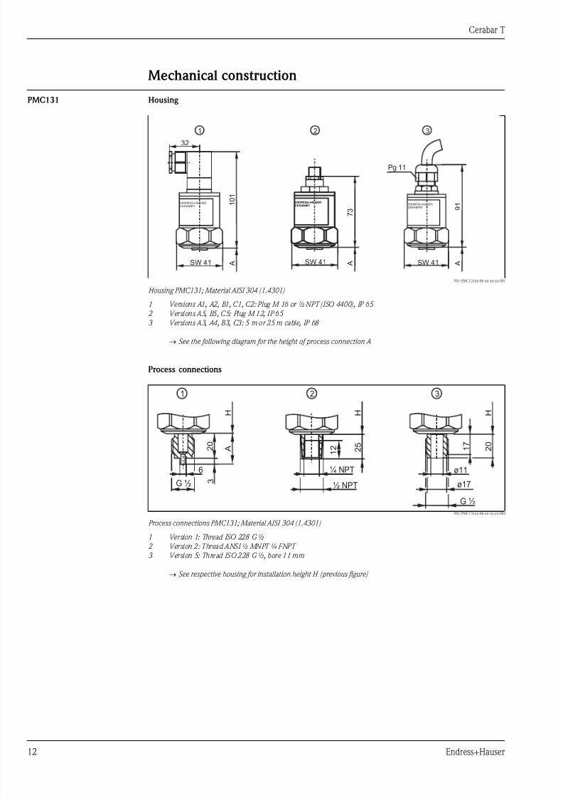
PMC131 Housing
P01-PMC131xx-06-xx-xx-xx-001
Housing PMC131; Material AISI 304 (1.4301)
1 Versions A1, A2, B1, C1, C2: Plug M 16 or ½ NPT (ISO 4400), IP 65
2 Versions A5, B5, C5: Plug M 12, IP 65
3 Versions A3, A4, B3, C3: 5 m or 25 m cable, IP 68
→ See the following diagram for the height of process connection A
Process connections
P01-PMC131xx-06-xx-xx-xx-002
Process connections PMC131; Material AISI 304 (1.4301)
1 Version 1: Thread ISO 228 G ½
2 Version 2: Thread ANSI ½ MNPT ¼ FNPT
3 Version 5: Thread ISO 228 G ½, bore 11 mm
→ See respective housing for installation height H (previous figure)
ENDRESS+HAUSER
CERABART
ENDRESS+HAUSER
CERABART
ENDRESS+HAUSER
CERABART
32
SW 41 SW 41
1 0 1
A
ENDRESS+HAUSER
CERABART
SW 41
9 1
7 3
A A
Pg 11
1 2 3
G ½
2 0
H
A
3
6
2 0
H
1 7
ø17
ø11
G ½
½ NPT
¼ NPT
1 2 2
5
H
1 2 3
7/27/2019 Sensor de Precion QTB
http://slidepdf.com/reader/full/sensor-de-precion-qtb 13/24
Cerabar T
Endress+Hauser 13
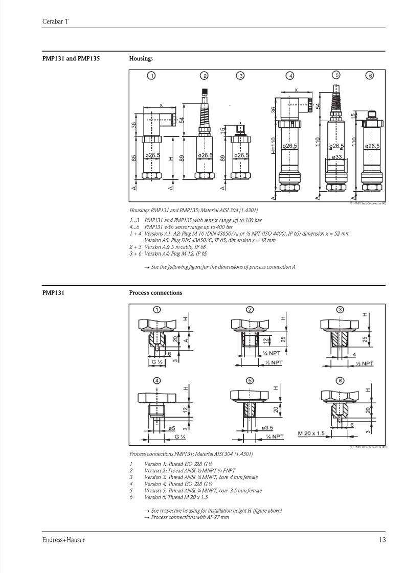
PMP131 and PMP135 Housing s
P01-PMP13xxx-06-xx-xx-xx-002
Housings PMP131 and PMP135; Material AISI 304 (1.4301)
1...3 PMP131 and PMP135 with sensor range up to 100 bar
4...6 PMP131 with sensor range up to 400 bar
1 + 4 Versions A1, A2: Plug M 16 (DIN 43650/A) or ½ NPT (ISO 4400), IP 65; dimension x = 52 mm
Version A5: Plug DIN 43650/C, IP 65; dimension x = 42 mm
2 + 5 Version A3: 5 m cable, IP 68
3 + 6 Version A4: Plug M 12, IP 65
→ See the following figure for the dimensions of process connection A
PMP131 Process connections
P01-PMP131xx-06-xx-xx-xx-002
Process connections PMP131; Material AISI 304 (1.4301)
1 Version 1: Thread ISO 228 G ½
2 Version 2: Thread ANSI ½ MNPT ¼ FNPT
3 Version 3: Thread ANSI ½ MNPT, bore 4 mm female
4 Version 4: Thread ISO 228 G ¼
5 Version 5: Thread ANSI ¼ MNPT, bore 3.5 mm female
6 Version 6: Thread M 20 x 1.5
→ See respective housing for installation height H (figure above)
→ Process connections with AF 27 mm
3 6
1 5
8 5
8 9
A A
H
A A A
A
5 4
8 9 ø26.5 ø26.5
ø26.5 ø26.5
ø33
ø26.5
ø26.5
x
x
3 6
1 1 0
1 5
H =
1 1 0
5 4
1 1 0
1 2 3 4 5 6
A
7/27/2019 Sensor de Precion QTB
http://slidepdf.com/reader/full/sensor-de-precion-qtb 14/24
Cerabar T
14 Endress+Hauser
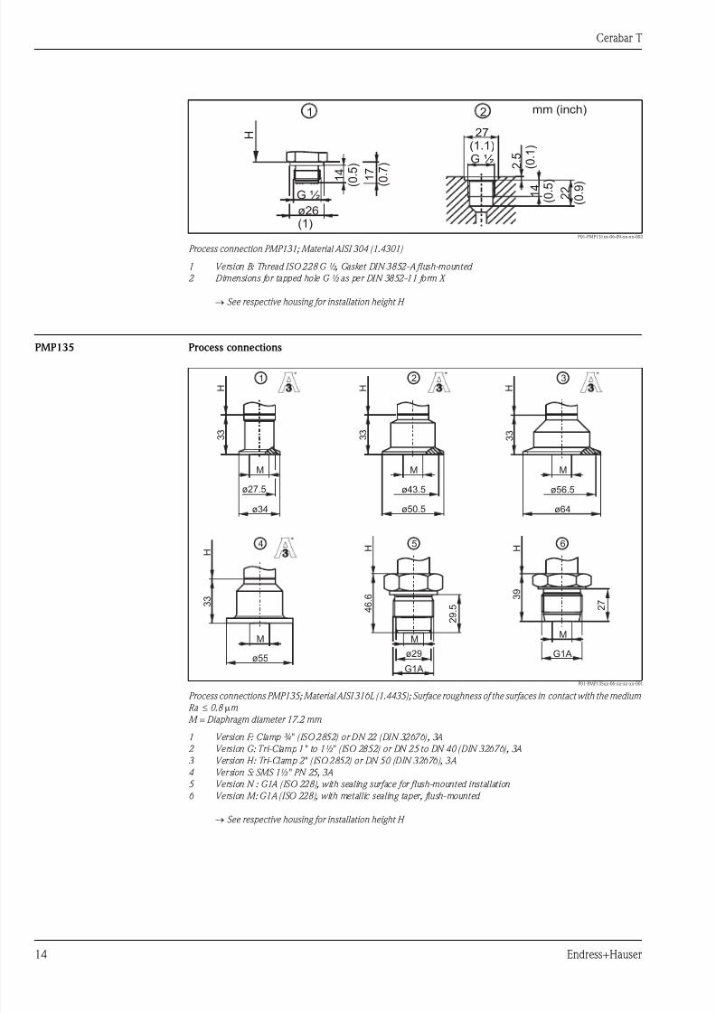
P01-PMP131xx-06-09-xx-xx-002
Process connection PMP131; Material AISI 304 (1.4301)
1 Version B: Thread ISO 228 G ½, Gasket DIN 3852-A flush-mounted
2 Dimensions for tapped hole G ½ as per DIN 3852-11 form X
→ See respective housing for installation height H
PMP135 Process connections
P01-PMP135xx-06-xx-xx-xx-001
Process connections PMP135; Material AISI 316L (1.4435); Surface roughness of the surfaces in contact with the medium Ra ≤ 0.8 μm
M = Diaphragm diameter 17.2 mm
1 Version F: Clamp ¾" (ISO 2852) or DN 22 (DIN 32676), 3A
2 Version G: Tri-Clamp 1" to 1½" (ISO 2852) or DN 25 to DN 40 (DIN 32676), 3A
3 Version H: Tri-Clamp 2" (ISO 2852) or DN 50 (DIN 32676), 3A
4 Version S: SMS 1½" PN 25, 3A
5 Version N : G1A (ISO 228), with sealing surface for flush-mounted installation
6 Version M: G1A (ISO 228), with metallic sealing taper, flush-mounted
→ See respective housing for installation height H
27(1.1)
1 4
( 0
. 5 )
2 . 5
( 0
. 1 )
2 2
( 0
. 9 )
G ½
H
1 2 mm (inch)
1 4 ( 0 . 5 )
G ½
ø26(1)
1 7
( 0 . 7
)
ø29
G1A
2 9
. 5 4 6
. 6
ø55
3 3
H
3 3
3 3
3 3
ø27.5
ø34
M M M
M M
ø50.5
ø43.5
ø64
ø56.5
H H
H H
1 2 3
4 5 H
G1A
2 7
3 9
M
6
7/27/2019 Sensor de Precion QTB
http://slidepdf.com/reader/full/sensor-de-precion-qtb 15/24
Cerabar T
Endress+Hauser 15
Weights • PMC131: approx. 0.32 kg
• PMP131: approx. 0.24 kg
• PMP135: approx. 0.34 kg
Material • Process connection:
– PMC131: AISI 304 (1.4301)– PMP131: AISI 304 (1.4301)
– PMP135: AISI 316L (1.4435)
• Sensor diaphragm:
– PMC131: Ceraphire® (99.9 % Al2O3), FDA number 21-CFR 186.1256
– PMP131, PMP135: AISI 316L (1.4435)
• Fill oil:
– PMP131: Tegiloxan 3
– PMP135: Mineral oil, FDA number 21-CFR 172.882
• Housing
AISI 304 (1.4301)
• Electrical connection
Plug M12: Polyamide (PA) Valve connector: Sheathing made of polyamide (PA)
Cable: Sheathing made of polyurethane (PUR/UL94, V0, UV-resistant)
Operating elements
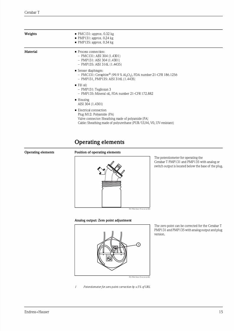
Operating elements Position of operating elements
Analog output: Zero point adjustment
P01-PMx13xxx-19-xx-xx-xx-003
The potentiometer for operating the
Cerabar T PMP131 and PMP135 with analog or
switch output is located below the base of the plug.
P01-PMx13xxx-19-xx-xx-xx-001
1 Potentiometer for zero point correction by ±5 % of URL
The zero point can be corrected for the Cerabar T
PMP131 and PMP135 with analog output and plug
version.
➪
1
7/27/2019 Sensor de Precion QTB
http://slidepdf.com/reader/full/sensor-de-precion-qtb 16/24
Cerabar T
16 Endress+Hauser
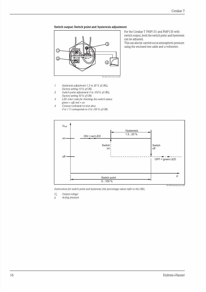
Switch output: Switch point and hysteresis adjustment
P01-PMP13xxx-05-xx-xx-en-001
Instructions for switch point and hysteresis (the percentage values refer to the URL)
U a Output voltage
p Acting pressure
P01-PMx13xxx-19-xx-xx-xx-002
1 Hysteresis adjustment 1.5 to 20 % of URL;
Factory setting 10 % of URL
2 Switch point adjustment 0 to 100 % of URL;
Factory setting 50 % of URL
3 LED color code for checking the switch status:
green = off; red = on
4 Connect voltmeter to test pins:
0 to 1 V corresponds to 0 to 100 % of URL
For the Cerabar T PMP131 and PMP135 with
switch output, both the switch point and hysteresis
can be adjusted.
This can also be carried out at atmospheric pressure
using the enclosed test cable and a voltmeter.
+–
1
2
3
4
pSwitch point
0...100 %
OFF = green LED
Switchoff
Uout
on
off
Hysteresis
1.5...20 %ON = red LED
Switchon
7/27/2019 Sensor de Precion QTB
http://slidepdf.com/reader/full/sensor-de-precion-qtb 17/24
Cerabar T
Endress+Hauser 17
Certificates and approvals
CE mark The device meets the legal requirements of the EC directives. Endress+Hauser confirms that the device has
been successfully tested by applying the CE mark.
Ex approvals All explosion protection data are given in separate documentation which is available upon request. The Ex
documentation is supplied as standard with all devices approved for use in explosion hazardous areas.
→ See also Page 22, "Safety Instructions" section.
Pressure Equipment Directive
(PED)
This measuring device corresponds to Article 3 (3) of the EC directive 97/23/EC (Pressure Equipment
Directive) and has been designed and manufactured according to good engineering practice.
Functional safety SIL 2 The Cerabar T PMP131 and PMP135 pressure transducers with 4 to 20 mA electronics have been assessed by
an independent body according to the standards IEC 61508/IEC 61511-1. These devices can be used for
monitoring process pressure up to SIL 2.
→ For a detailed description of safety functions with Cerabar T, settings and characteristic quantities for
functional safety, see the "Functional Safety Manual – Cerabar T SD160P".
Suitability for hygenicprocesses
TSE Certificate of Suitability Cerabar T PMP135
The following applies to wetted device components: They do not contain any materials derived from animals.
No auxiliaries or operating materials derived from animals are used in production or processing. Process wetted
device components are listed in the “Mechanical construction” and “Ordering information” sections.
Standards and guidelines DIN EN 60770 (IEC 60770):
Transmitters for controlling in systems used in industrial process technology
Part 1: Methods for evaluating the operating behavior.
DIN EN 61003-1, Edition:1993-12
Systems used in industrial process technology;
Devices with analog inputs and two-point or multi-point behavior;
Part 1: Methods for evaluating the operating behavior.
DIN 16086:
Electrical pressure measuring devices, pressure sensors, transmitters, pressure measuring devices
Terms, specifications in data sheets.
IEC 60592
Degrees of protection provided by enclosures (IP-Code).
EN 61326:
Electrical equipment for control technology and laboratory application – EMC requirements.
IEC 61010
Safety requirements for electrical equipment for measurement, control and laboratory use.
NAMUR
Association for Standards for Control and Regulation in the Chemical Industry.
Registered trademarks Ceraphire®
Registered trademark of Endress+Hauser GmbH+Co. KG, Maulburg, Germany
(→ see also www.endress.com/ceraphire)
The Cerabar T PMP135 is suitable for the employment in hygenicprocesses.
An overview of permitted process connections on page 14.
Many versions meet the requirements of 3A-Sanitary Standard No. 74
and are certified by the EHEDG.
! Note!
The gap-free connections can be cleaned without residue using the
usual cleaning methods. TYPE ELOctober 2007
74 -4 -
7/27/2019 Sensor de Precion QTB
http://slidepdf.com/reader/full/sensor-de-precion-qtb 18/24
Cerabar T
18 Endress+Hauser
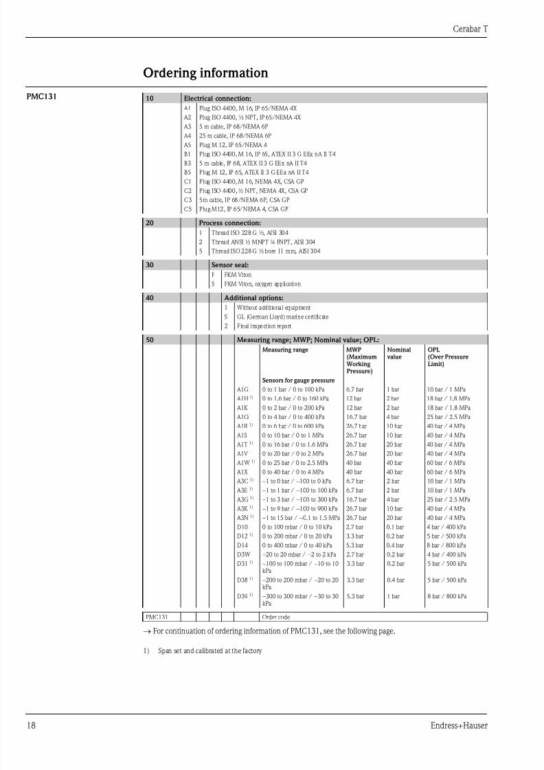
Ordering information
PMC131
→ For continuation of ordering information of PMC131, see the following page.
10 Electrical connection:
A1 Plug ISO 4400, M 16, IP 65/NEMA 4X
A2 Plug ISO 4400, ½ NPT, IP 65/NEMA 4X
A3 5 m cable, IP 68/NEMA 6P
A4 25 m cable, IP 68/NEMA 6P
A5 Plug M 12, IP 65/NEMA 4
B1 Plug ISO 4400, M 16, IP 65, ATEX II 3 G EEx nA II T4
B3 5 m cable, IP 68, ATEX II 3 G EEx nA II T4
B5 Plug M 12, IP 65, ATEX II 3 G EEx nA II T4
C1 Plug ISO 4400, M 16, NEMA 4X, CSA GP
C2 Plug ISO 4400, ½ NPT, NEMA 4X, CSA GP
C3 5m cable, IP 68/NEMA 6P, CSA GP
C5 Plug M12, IP 65/NEMA 4, CSA GP
20 Process connection:
1 Thread ISO 228 G ½, AISI 304
2 Thread ANSI ½ MNPT ¼ FNPT, AISI 304
5 Thread ISO 228 G ½ bore 11 mm, AISI 304
30 Sensor seal:F FKM Viton
S FKM Viton, oxygen application
40 Additional options:
1 Without additional equipment
S GL (German Lloyd) marine certificate
2 Final inspection report
50 Measuring range; MWP; Nominal value; OPL:
Measuring range MWP(Maximum
Working Pressure)
Nominal value
OPL (Over PressureLimit)
Sensors for gauge pressure
A1G 0 to 1 bar / 0 to 100 kPa 6.7 bar 1 bar 10 bar / 1 MPa
A1H 1) 0 to 1.6 bar / 0 to 160 kPa 12 bar 2 bar 18 bar / 1.8 MPa A1K 0 to 2 bar / 0 to 200 kPa 12 bar 2 bar 18 bar / 1.8 MPa
A1Q 0 to 4 bar / 0 to 400 kPa 16.7 bar 4 bar 25 bar / 2.5 MPa
A1R 1) 0 to 6 bar / 0 to 600 kPa 26.7 bar 10 bar 40 bar / 4 MPa
A1S 0 to 10 bar / 0 to 1 MPa 26.7 bar 10 bar 40 bar / 4 MPa
A1T 1) 0 to 16 bar / 0 to 1.6 MPa 26.7 bar 20 bar 40 bar / 4 MPa
A1V 0 to 20 bar / 0 to 2 MPa 26.7 bar 20 bar 40 bar / 4 MPa
A1W 1) 0 to 25 bar / 0 to 2.5 MPa 40 bar 40 bar 60 bar / 6 MPa
A1X 0 to 40 bar / 0 to 4 MPa 40 bar 40 bar 60 bar / 6 MPa
A3C 1) −1 to 0 bar / −100 to 0 kPa 6.7 bar 2 bar 10 bar / 1 MPa
A3E 1) −1 to 1 bar / −100 to 100 kPa 6.7 bar 2 bar 10 bar / 1 MPa
A3G 1) −1 to 3 bar / −100 to 300 kPa 16.7 bar 4 bar 25 bar / 2.5 MPa
A3K 1) −1 to 9 bar / −100 to 900 kPa 26.7 bar 10 bar 40 bar / 4 MPa
A3N 1) −1 to 15 bar / −0.1 to 1.5 MPa 26.7 bar 20 bar 40 bar / 4 MPa
D10 0 to 100 mbar / 0 to 10 kPa 2.7 bar 0.1 bar 4 bar / 400 kPa
D12 1) 0 to 200 mbar / 0 to 20 kPa 3.3 bar 0.2 bar 5 bar / 500 kPa
D14 0 to 400 mbar / 0 to 40 kPa 5.3 bar 0.4 bar 8 bar / 800 kPa
D3W −20 to 20 mbar / −2 to 2 kPa 2.7 bar 0.2 bar 4 bar / 400 kPa
D31 1) −100 to 100 mbar / −10 to 10kPa
3.3 bar 0.2 bar 5 bar / 500 kPa
D38 1) −200 to 200 mbar / −20 to 20kPa
3.3 bar 0.4 bar 5 bar / 500 kPa
D39 1) −300 to 300 mbar / −30 to 30kPa
5.3 bar 1 bar 8 bar / 800 kPa
PMC131 Order code
1) Span set and calibrated at the factory
7/27/2019 Sensor de Precion QTB
http://slidepdf.com/reader/full/sensor-de-precion-qtb 19/24
Cerabar T
Endress+Hauser 19
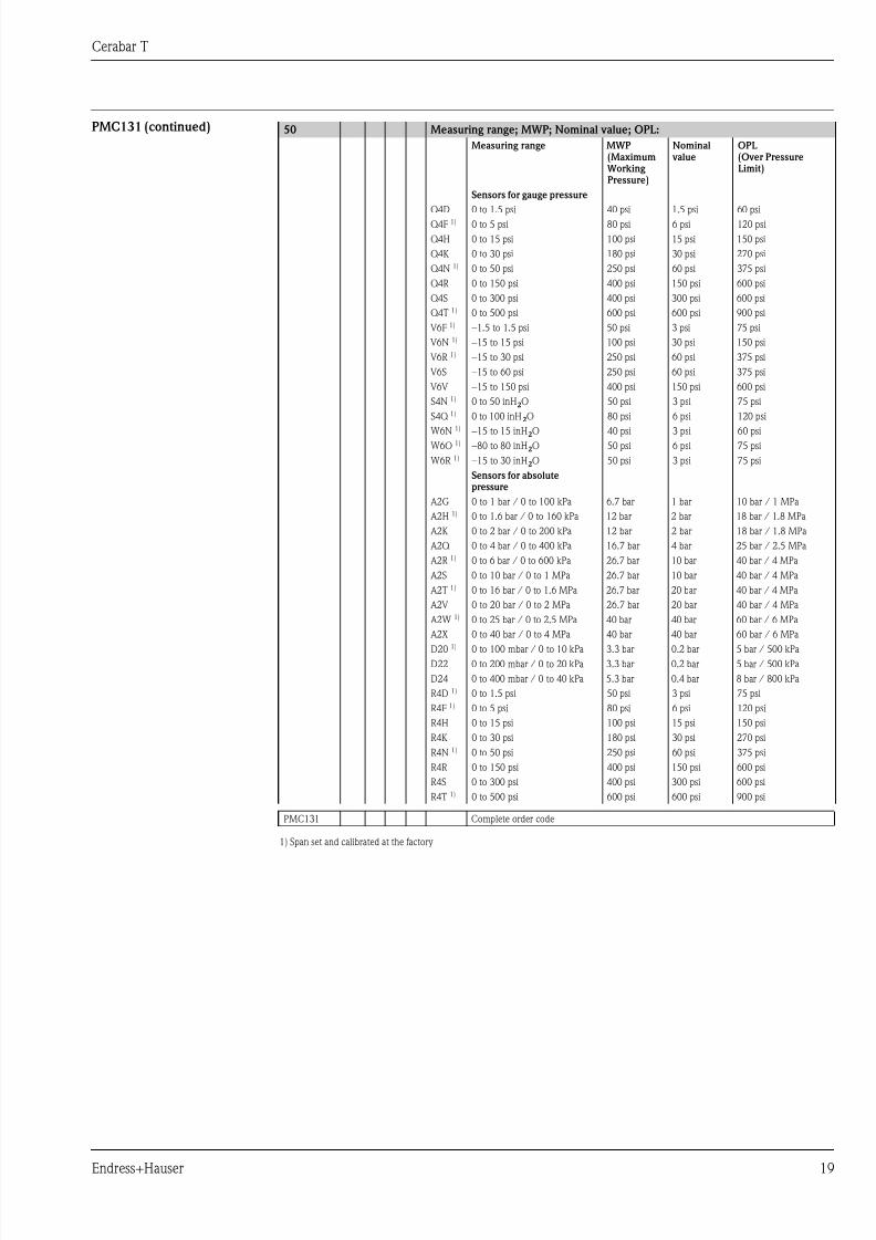
PMC131 (continued)
1) Span set and calibrated at the factory
50 Measuring range; MWP; Nominal value; OPL:
Measuring range MWP(Maximum
Working Pressure)
Nominal value
OPL (Over PressureLimit)
Sensors for gauge pressure
Q4D 0 to 1.5 psi 40 psi 1.5 psi 60 psiQ4F 1) 0 to 5 psi 80 psi 6 psi 120 psi
Q4H 0 to 15 psi 100 psi 15 psi 150 psi
Q4K 0 to 30 psi 180 psi 30 psi 270 psi
Q4N 1) 0 to 50 psi 250 psi 60 psi 375 psi
Q4R 0 to 150 psi 400 psi 150 psi 600 psi
Q4S 0 to 300 psi 400 psi 300 psi 600 psi
Q4T 1) 0 to 500 psi 600 psi 600 psi 900 psi
V6F 1) −1.5 to 1.5 psi 50 psi 3 psi 75 psi
V6N 1) −15 to 15 psi 100 psi 30 psi 150 psi
V6R 1) −15 to 30 psi 250 psi 60 psi 375 psi
V6S −15 to 60 psi 250 psi 60 psi 375 psi
V6V −15 to 150 psi 400 psi 150 psi 600 psi
S4N 1) 0 to 50 inH2O 50 psi 3 psi 75 psi
S4Q 1) 0 to 100 inH2O 80 psi 6 psi 120 psi
W6N 1) −15 to 15 inH2O 40 psi 3 psi 60 psi
W6O 1) −80 to 80 inH2O 50 psi 6 psi 75 psi
W6R 1) −15 to 30 inH2O 50 psi 3 psi 75 psi
Sensors for absolutepressure
A2G 0 to 1 bar / 0 to 100 kPa 6.7 bar 1 bar 10 bar / 1 MPa
A2H 1) 0 to 1.6 bar / 0 to 160 kPa 12 bar 2 bar 18 bar / 1.8 MPa
A2K 0 to 2 bar / 0 to 200 kPa 12 bar 2 bar 18 bar / 1.8 MPa
A2Q 0 to 4 bar / 0 to 400 kPa 16.7 bar 4 bar 25 bar / 2.5 MPa
A2R 1) 0 to 6 bar / 0 to 600 kPa 26.7 bar 10 bar 40 bar / 4 MPa
A2S 0 to 10 bar / 0 to 1 MPa 26.7 bar 10 bar 40 bar / 4 MPa
A2T 1) 0 to 16 bar / 0 to 1.6 MPa 26.7 bar 20 bar 40 bar / 4 MPa
A2V 0 to 20 bar / 0 to 2 MPa 26.7 bar 20 bar 40 bar / 4 MPa
A2W 1) 0 to 25 bar / 0 to 2.5 MPa 40 bar 40 bar 60 bar / 6 MPa
A2X 0 to 40 bar / 0 to 4 MPa 40 bar 40 bar 60 bar / 6 MPa
D20 1) 0 to 100 mbar / 0 to 10 kPa 3.3 bar 0.2 bar 5 bar / 500 kPa
D22 0 to 200 mbar / 0 to 20 kPa 3.3 bar 0.2 bar 5 bar / 500 kPa
D24 0 to 400 mbar / 0 to 40 kPa 5.3 bar 0.4 bar 8 bar / 800 kPa
R4D 1) 0 to 1.5 psi 50 psi 3 psi 75 psi
R4F 1) 0 to 5 psi 80 psi 6 psi 120 psi
R4H 0 to 15 psi 100 psi 15 psi 150 psi
R4K 0 to 30 psi 180 psi 30 psi 270 psi
R4N 1) 0 to 50 psi 250 psi 60 psi 375 psi
R4R 0 to 150 psi 400 psi 150 psi 600 psi
R4S 0 to 300 psi 400 psi 300 psi 600 psi
R4T 1) 0 to 500 psi 600 psi 600 psi 900 psi
PMC131 Complete order code
7/27/2019 Sensor de Precion QTB
http://slidepdf.com/reader/full/sensor-de-precion-qtb 20/24
Cerabar T
20 Endress+Hauser
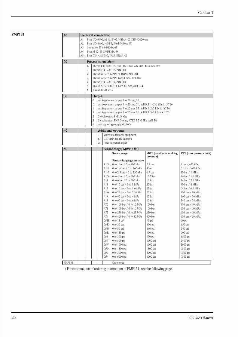
PMP131
→ For continuation of ordering information of PMP131, see the following page.
10 Electrical connection:
A1 Plug ISO 4400, M 16, IP 65/NEMA 4X (DIN 43650/A)
A2 Plug ISO 4400, ½ NPT, IP 65/NEMA 4X
A3 5 m cable, IP 68/NEMA 6P
A4 Plug M 12, IP 65/NEMA 4X
A5 Plug DIN 43650/C, IP65, NEMA 4X
20 Process connection:
B Thread ISO 228 G ½, Seal DIN 3852, AISI 304, flush-mounted
1 Thread ISO 228 G ½, AISI 304
2 Thread ANSI ½ MNPT ¼ FNPT, AISI 304
3 Thread ANSI ½ MNPT bore 4 mm, AISI 304
4 Thread ISO 228 G ¼, AISI 304
5 Thread ANSI ¼ MNPT bore 3.5 mm, AISI 304
6 Thread M 20 x 1.5
30 Output:
0 Analog current output 4 to 20 mA, SIL
D Analog current output 4 to 20 mA, SIL, ATEX II 1/2 G EEx ib IIC T6
1 Analog current output 4 to 20 mA, SIL, ATEX II 2 G EEx ib IIC T6
5 Analog current output 4 to 20 mA, SIL, ATEX II 3 G EEx nA II T6
2 Switch output PNP, 3-wire3 Switch output PNP, 3-wire, ATEX II 3 G EEx nA II T6
6 Analog voltage output 0...10 V
40 Additional options:
1 Without additional equipment
S GL/RINA marine approval
2 Final inspection report
50 Sensor range; MWP; OPL:
Sensor range MWP (maximum working pressure)
OPL (over pressure limit)
Sensors for gauge pressure
A1G 0 to 1 bar / 0 to 100 kPa 2.7 bar 4 bar / 400 kPa
A1H 0 to 1.6 bar / 0 to 160 kPa 4 bar 6.4 bar / 640 kPa
A1N 0 to 2.5 bar / 0 to 250 kPa 6.7 bar 10 bar / 1 MPa
A1Q 0 to 4 bar / 0 to 400 kPa 10.7 bar 16 bar / 1.6 MPa
A1R 0 to 6 bar / 0 to 600 kPa 16 bar 24 bar / 2.4 MPa
A1S 0 to 10 bar / 0 to 1 MPa 25 bar 40 bar / 4 MPa
A1T 0 to 16 bar / 0 to 1.6 MPa 25 bar 64 bar / 6.4 MPa
A1W 0 to 25 bar / 0 to 2.5 MPa 25 bar 100 bar / 10 MPa
A1X 0 to 40 bar / 0 to 4 MPa 60 bar 160 bar / 16 MPa
A1Z 0 to 60 bar / 0 to 6 MPa 60 bar 240 bar / 24 MPa
A70 0 to 100 bar / 0 to 10 MPa 100 bar 400 bar / 40 MPa
A71 0 to 160 bar / 0 to 16 MPa 160 bar 600 bar / 60 MPa
A73 0 to 250 bar / 0 to 25 MPa 250 bar 600 bar / 60 MPa
A74 0 to 400 bar / 0 to 40 MPa 400 bar 600 bar / 60 MPa
Q4H 0 to 15 psi 40 psi 60 psi
Q4K 0 to 30 psi 100 psi 150 psi
Q4N 0 to 50 psi 160 psi 240 psi
Q4R 0 to 150 psi 400 psi 600 psiQ4S 0 to 300 psi 400 psi 1500 psi
Q4T 0 to 500 psi 1000 psi 2400 psi
Q4V 0 to 1000 psi 1000 psi 3600 psi
Q70 0 to 1500 psi 1500 psi 6000 psi
Q73 0 to 3000 psi 3000 psi 9000 psi
Q74 0 to 6000 psi 6000 psi 9000 psi
PMP131 Order code
7/27/2019 Sensor de Precion QTB
http://slidepdf.com/reader/full/sensor-de-precion-qtb 21/24
Cerabar T
Endress+Hauser 21
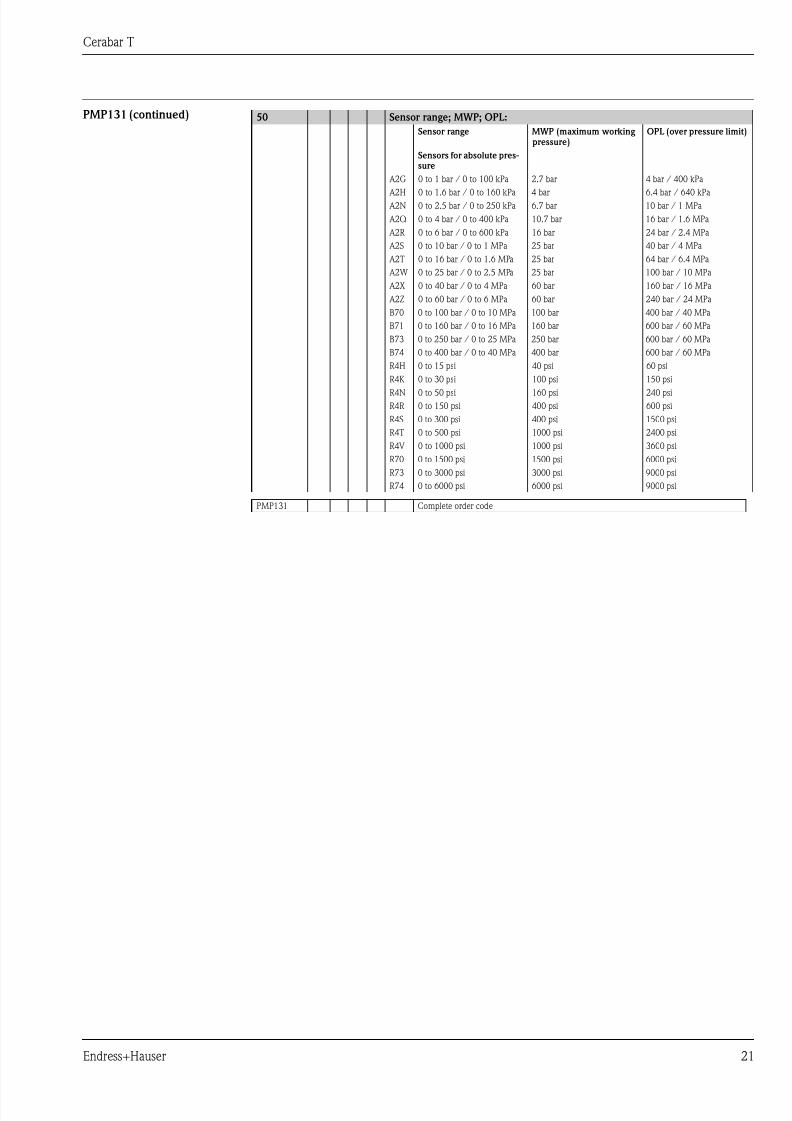
PMP131 (continued) 50 Sensor range; MWP; OPL:
Sensor range MWP (maximum working pressure)
OPL (over pressure limit)
Sensors for absolute pres-sure
A2G 0 to 1 bar / 0 to 100 kPa 2.7 bar 4 bar / 400 kPa
A2H 0 to 1.6 bar / 0 to 160 kPa 4 bar 6.4 bar / 640 kPa A2N 0 to 2.5 bar / 0 to 250 kPa 6.7 bar 10 bar / 1 MPa
A2Q 0 to 4 bar / 0 to 400 kPa 10.7 bar 16 bar / 1.6 MPa
A2R 0 to 6 bar / 0 to 600 kPa 16 bar 24 bar / 2.4 MPa
A2S 0 to 10 bar / 0 to 1 MPa 25 bar 40 bar / 4 MPa
A2T 0 to 16 bar / 0 to 1.6 MPa 25 bar 64 bar / 6.4 MPa
A2W 0 to 25 bar / 0 to 2.5 MPa 25 bar 100 bar / 10 MPa
A2X 0 to 40 bar / 0 to 4 MPa 60 bar 160 bar / 16 MPa
A2Z 0 to 60 bar / 0 to 6 MPa 60 bar 240 bar / 24 MPa
B70 0 to 100 bar / 0 to 10 MPa 100 bar 400 bar / 40 MPa
B71 0 to 160 bar / 0 to 16 MPa 160 bar 600 bar / 60 MPa
B73 0 to 250 bar / 0 to 25 MPa 250 bar 600 bar / 60 MPa
B74 0 to 400 bar / 0 to 40 MPa 400 bar 600 bar / 60 MPa
R4H 0 to 15 psi 40 psi 60 psi
R4K 0 to 30 psi 100 psi 150 psi
R4N 0 to 50 psi 160 psi 240 psi
R4R 0 to 150 psi 400 psi 600 psi
R4S 0 to 300 psi 400 psi 1500 psi
R4T 0 to 500 psi 1000 psi 2400 psi
R4V 0 to 1000 psi 1000 psi 3600 psi
R70 0 to 1500 psi 1500 psi 6000 psi
R73 0 to 3000 psi 3000 psi 9000 psi
R74 0 to 6000 psi 6000 psi 9000 psi
PMP131 Complete order code
7/27/2019 Sensor de Precion QTB
http://slidepdf.com/reader/full/sensor-de-precion-qtb 22/24
Cerabar T
22 Endress+Hauser
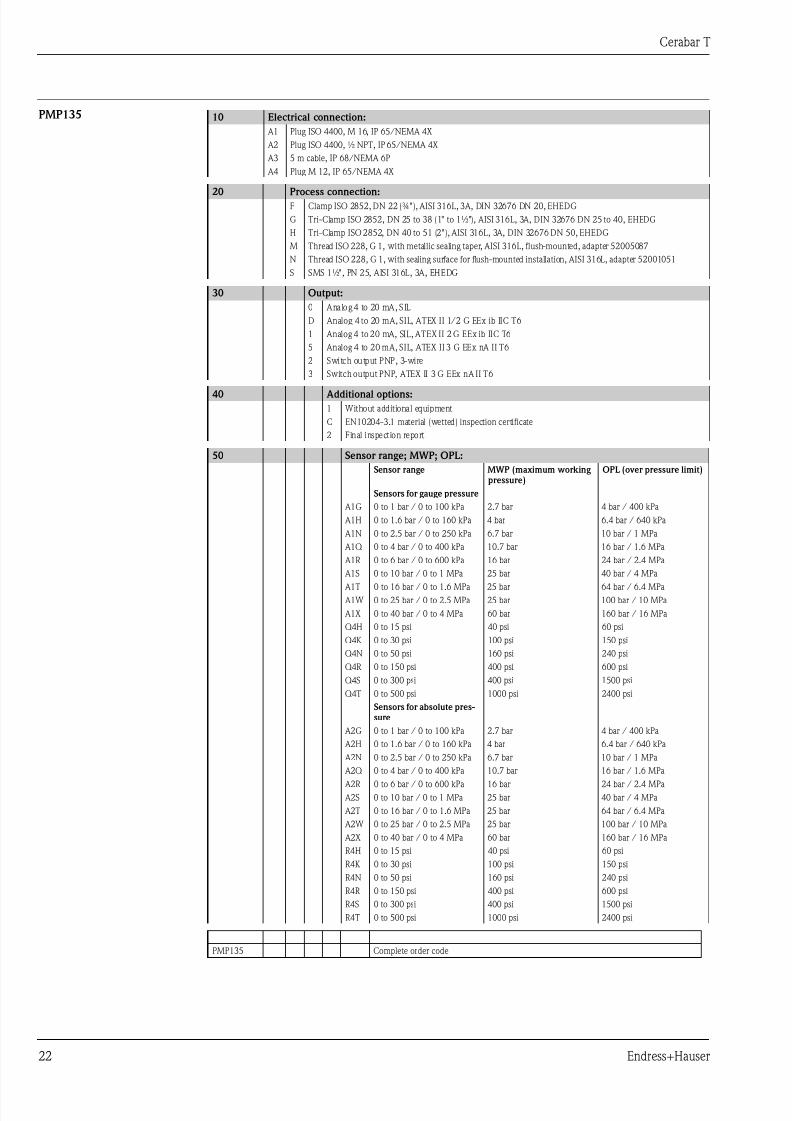
PMP135 10 Electrical connection:
A1 Plug ISO 4400, M 16, IP 65/NEMA 4X
A2 Plug ISO 4400, ½ NPT, IP 65/NEMA 4X
A3 5 m cable, IP 68/NEMA 6P
A4 Plug M 12, IP 65/NEMA 4X
20 Process connection:F Clamp ISO 2852, DN 22 (¾"), AISI 316L, 3A, DIN 32676 DN 20, EHEDG
G Tri-Clamp ISO 2852, DN 25 to 38 (1" to 1½"), AISI 316L, 3A, DIN 32676 DN 25 to 40, EHEDG
H Tri-Clamp ISO 2852, DN 40 to 51 (2"), AISI 316L, 3A, DIN 32676 DN 50, EHEDG
M Thread ISO 228, G 1, with metallic sealing taper, AISI 316L, flush-mounted, adapter 52005087
N Thread ISO 228, G 1, with sealing surface for flush-mounted installation, AISI 316L, adapter 52001051
S SMS 1½", PN 25, AISI 316L, 3A, EHEDG
30 Output:
0 Analog 4 to 20 mA, SIL
D Analog 4 to 20 mA, SIL, ATEX II 1/2 G EEx ib IIC T6
1 Analog 4 to 20 mA, SIL, ATEX II 2 G EEx ib IIC T6
5 Analog 4 to 20 mA, SIL, ATEX II 3 G EEx nA II T6
2 Switch output PNP, 3-wire
3 Switch output PNP, ATEX II 3 G EEx nA II T6
40 Additional options:
1 Without additional equipment
C EN10204-3.1 material (wetted) inspection certificate
2 Final inspection report
50 Sensor range; MWP; OPL:
Sensor range MWP (maximum working pressure)
OPL (over pressure limit)
Sensors for gauge pressure
A1G 0 to 1 bar / 0 to 100 kPa 2.7 bar 4 bar / 400 kPa
A1H 0 to 1.6 bar / 0 to 160 kPa 4 bar 6.4 bar / 640 kPa
A1N 0 to 2.5 bar / 0 to 250 kPa 6.7 bar 10 bar / 1 MPa
A1Q 0 to 4 bar / 0 to 400 kPa 10.7 bar 16 bar / 1.6 MPa
A1R 0 to 6 bar / 0 to 600 kPa 16 bar 24 bar / 2.4 MPa
A1S 0 to 10 bar / 0 to 1 MPa 25 bar 40 bar / 4 MPa
A1T 0 to 16 bar / 0 to 1.6 MPa 25 bar 64 bar / 6.4 MPa
A1W 0 to 25 bar / 0 to 2.5 MPa 25 bar 100 bar / 10 MPa
A1X 0 to 40 bar / 0 to 4 MPa 60 bar 160 bar / 16 MPa
Q4H 0 to 15 psi 40 psi 60 psi
Q4K 0 to 30 psi 100 psi 150 psi
Q4N 0 to 50 psi 160 psi 240 psi
Q4R 0 to 150 psi 400 psi 600 psi
Q4S 0 to 300 psi 400 psi 1500 psi
Q4T 0 to 500 psi 1000 psi 2400 psi
Sensors for absolute pres-sure
A2G 0 to 1 bar / 0 to 100 kPa 2.7 bar 4 bar / 400 kPa
A2H 0 to 1.6 bar / 0 to 160 kPa 4 bar 6.4 bar / 640 kPa
A2N 0 to 2.5 bar / 0 to 250 kPa 6.7 bar 10 bar / 1 MPa
A2Q 0 to 4 bar / 0 to 400 kPa 10.7 bar 16 bar / 1.6 MPa A2R 0 to 6 bar / 0 to 600 kPa 16 bar 24 bar / 2.4 MPa
A2S 0 to 10 bar / 0 to 1 MPa 25 bar 40 bar / 4 MPa
A2T 0 to 16 bar / 0 to 1.6 MPa 25 bar 64 bar / 6.4 MPa
A2W 0 to 25 bar / 0 to 2.5 MPa 25 bar 100 bar / 10 MPa
A2X 0 to 40 bar / 0 to 4 MPa 60 bar 160 bar / 16 MPa
R4H 0 to 15 psi 40 psi 60 psi
R4K 0 to 30 psi 100 psi 150 psi
R4N 0 to 50 psi 160 psi 240 psi
R4R 0 to 150 psi 400 psi 600 psi
R4S 0 to 300 psi 400 psi 1500 psi
R4T 0 to 500 psi 1000 psi 2400 psi
PMP135 Complete order code
7/27/2019 Sensor de Precion QTB
http://slidepdf.com/reader/full/sensor-de-precion-qtb 23/24
Cerabar T
Endress+Hauser 23
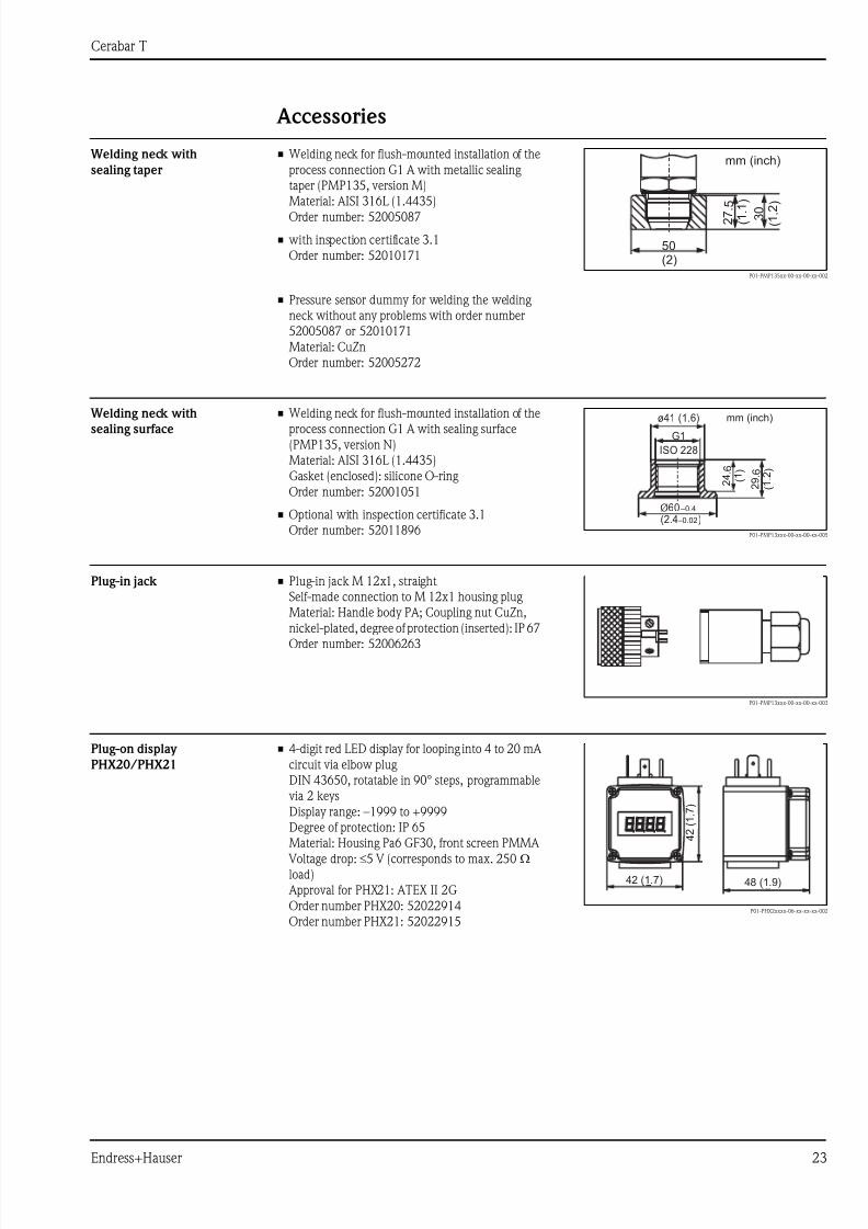
Accessories
Welding neck with
sealing taper
Welding neck with
sealing surface
Plug-in jack
Plug-on display
PHX20/PHX21
• Welding neck for flush-mounted installation of the
process connection G1 A with metallic sealing
taper (PMP135, version M)
Material: AISI 316L (1.4435)
Order number: 52005087
• with inspection certificate 3.1
Order number: 52010171
P01-PMP135xx-00-xx-00-xx-002
• Pressure sensor dummy for welding the welding
neck without any problems with order number
52005087 or 52010171
Material: CuZn
Order number: 52005272
50(2)
3 0 (
1 . 2
)
2 7 . 5
( 1 . 1 )
mm (inch)
• Welding neck for flush-mounted installation of the
process connection G1 A with sealing surface
(PMP135, version N)
Material: AISI 316L (1.4435)
Gasket (enclosed): silicone O-ring
Order number: 52001051
• Optional with inspection certificate 3.1
Order number: 52011896 P01-PMP13xxx-00-xx-00-xx-005
Ø60 –0.4
–0.02(2.4 )
2 4
. 6
( 1 )
2 9
. 6
( 1
. 2 )
ø41 (1.6)
G1
ISO 228
mm (inch)
• Plug-in jack M 12x1, straight
Self-made connection to M 12x1 housing plug
Material: Handle body PA; Coupling nut CuZn,
nickel-plated, degree of protection (inserted): IP 67
Order number: 52006263
P01-PMP13xxx-00-xx-00-xx-003
• 4-digit red LED display for looping into 4 to 20 mA
circuit via elbow plug
DIN 43650, rotatable in 90° steps, programmable
via 2 keys
Display range: –1999 to +9999
Degree of protection: IP 65
Material: Housing Pa6 GF30, front screen PMMA Voltage drop: ≤5 V (corresponds to max. 250 Ωload)
Approval for PHX21: ATEX II 2G
Order number PHX20: 52022914
Order number PHX21: 52022915P01-PHX2xxxx-06-xx-xx-xx-002
4842
42
4 2
( 1
. 7 )
42 (1.7) 48 (1.9)
7/27/2019 Sensor de Precion QTB
http://slidepdf.com/reader/full/sensor-de-precion-qtb 24/24
Documentation
Field of Activities • Pressure measurement, powerful measuring devices for process pressure, differential pressure, level
and flow: FA004P/00/en
Technical Information • EMC test procedures: TI241F/00/en
Operating Instructions • Cerabar T PMC131: KA085P/00/a3
• Cerabar T PMP131: KA103P/00/a3
• Cerabar T PMP135: KA198P/00/a3
Functional Safety Manual (SIL) • Cerabar T PMP131, PMP135: SD160P/00/en
Safety Instructions Cerabar T PMC131
• ATEX II 3 G EEx nA II T4: XA191P/00/a3
Cerabar T PMP131
• ATEX II 1/2 G or 2 G EEx ib IIC T6: XA142P/00/a3
• ATEX II 3 G EEx nA II T6: XA191P/00/a3
Cerabar T PMP135
• ATEX II 1/2 G or 2 G EEx ib IIC T6: XA142P/00/a3
• ATEX II 3 G EEx nA II T6: XA191P/00/a3
Instruments International
Endress+HauserInstruments International AGKaegenstrasse 24153 ReinachSwitzerland
Tel. +41 61 715 81 00Fax +41 61 715 25 00
TI415P/00/en/07 08