sa-nbs (mattstetten – rothrist) · sa-nbs (mattstetten – rothrist) document-control-sheet ......
TRANSCRIPT


SA-NBS (Mattstetten – Rothrist) Document-Control-Sheet
Specifications of DMI Ergonomics © by SBB page 2 / 59 04sys643v18.doc Version V 1.8 17.10.2006
Document-Control-Sheet
Content Specifications of ergonomic improvements of the Driver Machine Interface
Written by Elise Saint-Gelais Andreas Indermühle
Wordprozessor Microsoft Word 2000
Filename 04sys643v18.doc
Status of document working / in review / released
Distribution List Alstom Belgium
Amendment Record
Version Date Written by Modifications
X 1.0 06.12.2004 E. Saint-Gelais First issue of the document
X 1.1 09.12.2004 E. Saint-Gelais Upgrade following review comments rv_s643_x10_00
V 1.1 09.12.2004 A. Indermühle Introduction and release
V 1.2 21.12.2004 A. Indermühle New: Chapter 9
V 1.3 08.04.2005 E. Saint-Gelais Complete reissue of the document
V 1.4 02.05.2005 E. Saint-Gelais Upgrade following review comments rv_s643_v13_In rv_s643_v13_PS rv_s643_v13_heac
V 1.5 26/07/2005 A. Indermühle Refs 2, 10: Version updated; 3.6.1.1: SR data added in menu Sections: 4.2.6.1, 4.2.8.1, 5.2, 5.3, 5.4, 5.5, 5.6: Compliance with CENELEC Sections 5.1.1.2, 5.1.1.3: Added for clarification

SA-NBS (Mattstetten – Rothrist) Document-Control-Sheet
Specifications of DMI Ergonomics © by SBB page 3 / 59 04sys643v18.doc Version V 1.8 17.10.2006
V 1.6 21/03/2006 A. Indermühle The following section have been changed in order to reflect the implementation by Alstom:
Fig 6: red colour removed
Fig. 8 “zurück” button removed
2.2.5.1: No red colour for “rejected” state
3.3.1.5: Rejected replaced by non-validated
3.4.1.15/33/35: Return to first level menu, not data menu; reference to Fig 12 instead Fig 13.
3.4.1.25/26: 6 replaced by 5
3.6.2.2: Clarified
3.6.4.2: Return to first level menu; delay time deleted
3.6.4.3: RBC data entry removed, reworded
3.6.4.4: New section for RBC data entry
4.1.3.2, second bullet: Activation of status changed
4.1.3.3: Second sentence deleted
Tab 9: RSM/NoS: White
Tab 10: RSM, NoS: yellow/dark yellow
4.1.8.3 (Fig. 30): Changed Sections not implemented in the frame of the SA-NBS project marked in grey.
V 1.7 04/04/2006 A. Indermühle According to review comments rv_s643_v16_WB.doc. Major changes:
Fig 9: Deleted
Fig 13: Button “SR data” added
Fig 16, 3.6.3.7 (Tab. 6): Position of buttons “R/P” and “G” exchanged
4.1.6.5 (Tab. 9): Correction for CSM, pointer between 0 . v_target: N/A
4.1.7.4 (Tab. 10): Clarification for TSM/CSG between v_target – v_perm
Tab 16/17 gelöscht.
5.4 (Tab 21): Icon “Non stopping area activated by driver” yellow.
V 1.8 17/10/2006 A. Indermühle Section 1.1.1.6 and reference [11] added.

SA-NBS (Mattstetten – Rothrist) Table of Contents
Specifications of DMI Ergonomics © by SBB page 4 / 59 04sys643v18.doc Version V 1.8 17.10.2006
Table of Contents
1 Introduction 10
2 General Ergonomic Principles 11
2.1 Physical Parameters 11 2.1.1 Screen Size and Type 11 2.1.2 Day and Night Function 11 2.1.3 Brightness 12
2.2 General Arrangement of Information 13 2.2.1 Screen Structure 13 2.2.2 Colour Definition 15 2.2.3 Representation of the DMI and its Elements 15 2.2.4 Backgrounds Specification 18 2.2.5 Fonts Specification 19
3 Data Entry Procedure 23
3.2 Train and System Start-Up 23
3.3 ZUB Data Entry 23
3.4 Start of Mission in Level 0, UN mode 24
3.5 Data Modification 31
3.6 General Principles on Data Entry/Modification Procedure 32 3.6.1 Structure of Data Entry/Modification Menu (informative) 32 3.6.2 Navigation Keys 32 3.6.3 Input of Data 33 3.6.4 Data Entry Screen Closing 34 3.6.5 Concept of Full Window for Data Entry/Modification 34 3.6.6 Concept of Full Window for Data Confirmation 35 3.6.7 Concept of Partial Window for Data Entry/Modification 36 3.6.8 Partial Window for Data Confirmation 37 3.6.9 Data Confirmation Window 38 3.6.10 Sequence of the Data in Train Data Entry 38 3.6.11 Menu Closing 38
4 Driving Information 39
4.1 Speed and Supervision Information 39 4.1.2 Supervision Limits 39 4.1.3 Speed Monitoring 40 4.1.4 Colour Definition 40 4.1.5 Speed Dial 41 4.1.6 Current Train Speed Pointer 42 4.1.7 Circular Speed Gauge (CSG) 43
SA-NBS (Mattstetten – Rothrist) Table of Contents
Specifications of DMI Ergonomics © by SBB page 5 / 59 04sys643v18.doc Version V 1.8 17.10.2006
4.1.8 Release Speed 45 4.1.9 Set Speed Indicator 45 4.1.10 Distance to Target 46 4.1.11 Warning Time to Intervention 46 4.1.12 Display of Icons in the “Actual Orders Area” 46 4.1.13 Geographical Position 46
4.2 Planning Information 47 4.2.2 Colour Definition 47 4.2.3 Speed Profile 48 4.2.4 Distance Scale 48 4.2.5 Gradient Profile 48 4.2.6 Speed Related Target 49 4.2.7 Special Requirements for Display of the “Speed Related Target” Icons 49 4.2.8 Brake Curve Area Starting Point 49 4.2.9 Buttons to zoom the planning area 49 4.2.10 Display of Icons in the “Actual Order Area” 50
5 Symbols (informative) 51
5.2 Monitor Symbols 51
5.3 Mode Symbols 52
5.4 Orders and Indications of Route Condition Symbols 53
5.5 Planning Area Symbols 55
5.6 GSM-R Radio Communication Symbols 56
6 Data Entry Performance Specification 58
6.1 Start of Mission for SH Movement 58
6.2 Start of Mission for Train Movement I 58
6.3 Start of Mission for Train Movement II 58
6.4 Change of Data 58
6.5 General Remark 58
7 Documentation Requirements 59

SA-NBS (Mattstetten – Rothrist) List of Tables
Specifications of DMI Ergonomics © by SBB page 6 / 59 04sys643v18.doc Version V 1.8 17.10.2006
List of Tables
Tab. 1 Brightness Definition 12
Tab. 2 Colour Definition 15
Tab. 3 Backgrounds Specifications 19
Tab. 4 Fonts Specifications 22
Tab. 5 Menu Structure 32
Tab. 6 “Brake Type” Keyboard 33
Tab. 7 “Level” Keyboard 33
Tab. 8 Colour Definition 41
Tab. 9 Colour Specification of Current Train Speed Pointer 43
Tab. 10 Colour Specification of Circular Speed Gauge 44
Tab. 11 Conditions for Display of the Distance to Target 46
Tab. 12 Colour Definition 47
Tab. 13 Speed Profile Specifications 48
Tab. 14 Distance Scale Specifications 48
Tab. 15 Gradient Profile Specifications 48
Tab. 18 Zoom 50
Tab. 19 Monitor Symbols 52
Tab. 20 Mode Symbols 53
Tab. 21 Orders and Indications of Route Condition Symbols 55
Tab. 22 Planing Area Symbols 56
Tab. 23 GSM-R Radio Communication Symbols 57
Tables 16/17 deleted

SA-NBS (Mattstetten – Rothrist) List of Figures
Specifications of DMI Ergonomics © by SBB page 7 / 59 04sys643v18.doc Version V 1.8 17.10.2006
List of Figures
Fig. 1 Brightness Definition 12
Fig. 2 Screen Structure: Main Areas 13
Fig. 3 Screen Structure: Sub-areas 14
Fig. 4 Screen Structure for the Data Entry 14
Fig. 5 Presentation a Menu Screen 15
Fig. 6 Presentation of a Data Entry/Modification Screen 16
Fig. 7 Presentation a Data Confirmation Screen 17
Fig. 8 Presentation of a Data View Screen 18
Fig. 9 deleted 23
Fig. 10 Driver ID 24
Fig. 11 Level Confirmation 25
Fig. 12 First Level Menu 25
Fig. 13 Data Menu 26
Fig. 14 Train Running Number 26
Fig. 15 Train Data Menu 27
Fig. 16 Train Data Entry 28
Fig. 17 Train Data Entry, “End“ Button 29
Fig. 18 Train Data Confirmation 30
Fig. 19 Mode Menu 31
Fig. 20 Level Selection 34
Fig. 21 Full Window for Data Entry/Modification 35
Fig. 22 Full Window for Data Confirmation 36
Fig. 23 Partial Window for Data Entry/Modification 37
Fig. 24 Partial Window for Data Confirmaiton 37
Fig. 25 Elements of Speed and Supervision Areas 39
Fig. 26 Supervision Limits and Speed Monitoring 40
Fig. 27 Speed Dial with 260 km/h Scale 42
Fig. 28 Current train speed pointer (dimensions are in pixels) 42
Fig. 29 Circular Speed Gauge Dimensions (in pixels) 44
Fig. 30 Display of Release Speed (fonts and ticks are not compliant with these specifications) 45
Fig. 31 “Set Speed Indicator“ Specifications 45
Fig. 32 Elements of Planning Area 47

SA-NBS (Mattstetten – Rothrist) Abbreviations
Specifications of DMI Ergonomics © by SBB page 8 / 59 04sys643v18.doc Version V 1.8 17.10.2006
Abbreviations
AllS All Status
BK Bottom Key
BTS Braking to Target Speed Section
CSM Ceiling Speed Monitoring
DMI Driver Machine Interface
EEIG European Economic Interest Group
EoA End of Authority
ERTMS European Railway Traffic Management System
ETCS European Train Control System
EVC European Vital Computer
IndS Indication Status
IntS Intervention Speed Status
LoA Limit of Authority
MVB the machine bus communicating the value of the set speed
MRSP Most Restrictive Speed Profile
NoFS Not in Full Supervision Mode
NoS No Status Active
OvS Over-speed Status
PreS Pre-indication Status
RBC Radio Block Centre
RGB Red Green Blue colours code
RSM Release Speed Monitoring
SB Stand By mode
SH Shunting mode
SoM Start of Mission
SR Staff Responsible mode
SRS System Requirements Specification
SSP Static Speed Profile
TIU Train interface unit
TSR Temporary Speed Restriction
TSM Target Speed Monitoring
UN Unfitted mode

SA-NBS (Mattstetten – Rothrist) Abbreviations
Specifications of DMI Ergonomics © by SBB page 9 / 59 04sys643v18.doc Version V 1.8 17.10.2006
VInt Intervention Speed
VPerm Permitted Speed
VRelease Release Speed
VTarget Target Speed
VTrain Current Speed of the Train
v_LoA Speed at LoA
WaS Warning Speed Status
ZUB Zugbeeinflussungsystem
References [1] Driver Interface, Version V2.0, BSI_SR_GATC_M_DESG_0040
[2] DMI Configuration for ETCS Application, Version V4.4, 03sys606v44
[3] ZUB screen design and behaviour, Version V1.2, 04sys482v12
[4] System Requirements Specification, Version 2.2.2, subset-026
[5] INOVEX, ergonomie & technologie, STEAG: Ergonomiestudie DMI für ETCS, Schlussbericht [pre-final], Version 3.0
[6] Railways applications – Communication, signalling and processing systems – European Rail Traffic Management System – Driver-Machine Interface – Part 1: Ergonomic principles for the presentation of ERTMS/ETCS/GSM-R information, Version Februar 2005 Draft, CLC/TS 50459-1
[7] Railways applications – Communication, signalling and processing systems – European Rail Traffic Management System – Driver-Machine Interface – Part 2: Ergonomic arrangements of ERTMS/ETCS information, Version Februar 2005 Draft, CLC/TS 50459-2
[8] Railways applications – Communication, signalling and processing systems – European Rail Traffic Management System – Driver-Machine Interface – Part 4: Data entry for the ERTMS/ETCS/GSM-R systems, Version Februar 2005 Draft, CLC/TS 50459-4
[9] Railways applications – Communication, signalling and processing systems – European Rail Traffic Management System – Driver-Machine Interface – Part 5: Symbols, Version Februar 2005 Draft, CLC/TS 50459-5
[10] Operational DMI Information – ERTMS Operational Rules Group, Version 3-, 11/07/05, 04E296
[11] Alstom, DMI Red Software status, SA-NBS_BSI_0858_MEMO, Issue 4

SA-NBS (Mattstetten – Rothrist) Introduction
Specifications of DMI Ergonomics © by SBB page 10 / 59 04sys643v18.doc Version V 1.8 17.10.2006
1 Introduction 1.1.1.1 This specification describes SBB’s requirements on the ergonomics of the ETCS DMI in
the project SA-NBS.
1.1.1.2 This specification is based on a ergonomic study ordered by SBB at a specialised com-pany [5] and a study of CENELEC requirements (Ref. [6] to [9]).
1.1.1.3 After discussion between the supplier (Alstom) and SBB, some of the requirements may be denominated as not feasible in the frame of the project. This non-applicable require-ments shall then be printed in grey font in further issues of this document.
1.1.1.4 Furthermore, this document shall serve as a nucleus for a more generic requirements specification of the DMI on Swiss ETCS projects.
1.1.1.5 This document shall also be passed to the “EEIG ERTMS operational rules group” as an input for the standardisation.
1.1.1.6 After fine tuning of the DMI, the implementation of some requirements and figures is not exactly following the current specification. The changes are addressed in the Alstom memorandum [11].

SA-NBS (Mattstetten – Rothrist) General Ergonomic Principles
Specifications of DMI Ergonomics © by SBB page 11 / 59 04sys643v18.doc Version V 1.8 17.10.2006
2 General Ergonomic Principles 2.1 Physical Parameters
2.1.1 Screen Size and Type
2.1.1.1 Form and shape of the information on the screen is based on a total grid area of 640*480 pixels for a minimum screen size with 10.4 inches diagonal. This ratio forms the basis for proportions of objects or elements independent of the resolution and size of the screen.
2.1.1.2 The visual appearance shall be kept even if the information is displayed on more than one screen or if a different grid array is used.
2.1.2 Day and Night Function
2.1.2.1 The driver shall have the possibility to switch between a day background called “day mode” and a night background called “night mode”. This shall be considered as a “day and night function”.
2.1.2.2 The “day and night function” shall have an automatic and a manual mode.
2.1.2.3 If the “day and night function” is in the automatic mode, the DMI background shall switch automatically from one day or night mode to the other depending on the ambient cab lighting.
2.1.2.4 If the “day and night function” is in the manual mode, there is no automatic switch from one mode to the other, but the driver is able to select manually the day or night back-ground.
2.1.2.5 The default settings when opening the driver desk shall be:
DMI background in NIGHT mode
“Day and night function” in MANUAL mode
2.1.2.6 The “day mode” and the automatic mode of the “day and night function” shall still be available to the driver as he shall have the possibility to switch free between night and day mode or to use the automatic mode of the “day and night function”.
2.1.2.7 No special icon or text is requested to indicate to the driver which “day or night mode“ and which “automatic or manual function” are currently active.

SA-NBS (Mattstetten – Rothrist) General Ergonomic Principles
Specifications of DMI Ergonomics © by SBB page 12 / 59 04sys643v18.doc Version V 1.8 17.10.2006
2.1.3 Brightness
2.1.3.1 The brightness of a DMI screen is defined as follow:
Fig. 1 Brightness Definition
Adjustement for:
Down1 Down2 Up1 Up2 Bright. Min Bright. Max
LH 1 2 120 160 10 250
MH 1 2 135 170 20 250
HH 1 2 120 160 40 250
LL 1 2 190 210 10 210
Tab. 1 Brightness Definition
Cab Lighting
Scre
en B
right
ness
File ...070704_LH
File ...070704_HH
File ...070704_MH
File ...070704_LL
10 20 30 40 50 60
10
20
30
40
50
60
70
80
180 190 200 210
210
250
165
SA-NBS (Mattstetten – Rothrist) General Ergonomic Principles
Specifications of DMI Ergonomics © by SBB page 13 / 59 04sys643v18.doc Version V 1.8 17.10.2006
2.1.3.2 The configuration of the brightness shall be implemented following the LL configuration including 10 steps to increase the value from the minimum level to the maximal level in manual mode.
2.1.3.3 The DMI shall give two possibilities for the brightness control: automatic adjustment (de-pending on the ambient cab lighting) and manual adjustment.
2.1.3.4 The driver shall also have the possibility to switch between these automatic and manual adjustments of the brightness control.
2.1.3.5 The default settings when opening the driver desk shall be:
The middle position of the defined scale
The MANUAL adjustment of the brightness control
2.1.3.6 No special icon or text is requested to indicate to the driver which automatic or manual adjustment is currently active and what is the current position in the brightness scale.
2.2 General Arrangement of Information
2.2.1 Screen Structure
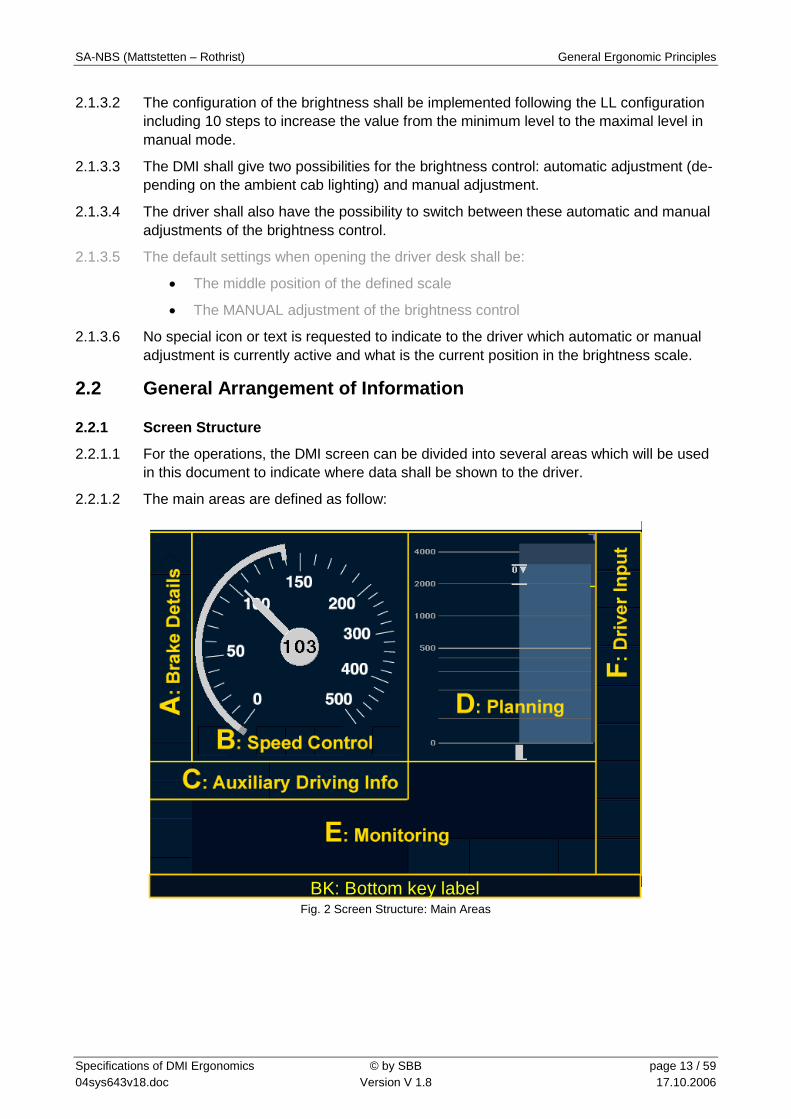
2.2.1.1 For the operations, the DMI screen can be divided into several areas which will be used in this document to indicate where data shall be shown to the driver.
2.2.1.2 The main areas are defined as follow:
Fig. 2 Screen Structure: Main Areas
BK: Bottom key label

SA-NBS (Mattstetten – Rothrist) General Ergonomic Principles
Specifications of DMI Ergonomics © by SBB page 14 / 59 04sys643v18.doc Version V 1.8 17.10.2006
2.2.1.3 Each main area is composed of a set of sub-areas which are used to display icons, text messages, etc. These sub-areas are defined as follow:
Fig. 3 Screen Structure: Sub-areas
2.2.1.4 For the data entry, the DMI screen can be represented using following structure:
Fig. 4 Screen Structure for the Data Entry
2.2.1.5 The area P is composed of the areas M, N and O.
2.2.1.6 The area Q is composed of the area P minus the areas E19 to E23 which are reserved for text messages.
B0 (280*300)
BK1(54*30)
A1(54*54)
A2(54*222)
A3 (54*24)
C8 (54*25)
C9 (54*25)
C5(40*50)
C6(40*50) C2
C1(40*50)
C7(40*50)
C2(40*50)
C4(40*50)
C3(40*50)
E1 (54*25)
E5 (54*25)
E4 (54*25)
E3 (54*25)
BK2(53*30)
BK3(53*30)
BK4(54*30)
BK5(53*30)
BK6(53*30)
BK7(54*30)
BK8(53*30)
BK9(53*30)
BK10(54*30)
BK11(53*30)
BK12(53*30)
F1(60*50)
F9(60*50)
F8(60*50)
F7(60*50)
F6(60*50)
F5(60*50)
F4(60*50)
F3(60*50)
F2(60*50)
E19 (280*20)E20 (280*20)E21 (280*20)E22 (280*20)E23 (280*20)
E7(49*50)
E10(49*50)
E9(49*50)
E8(49*50)
E6(49*50)
E12(49*50)
E15(49*50)
E14(49*50)
E13(49*50)
E11(49*50)
E17(49*50)
E16a(82*50)
E16b(114*50)
D(246*300)
B2
B1(60)
B6(36*36)
B7(36*36)
B5(36*36)
B4(36*36)
B3(36*36)
D1(30*300)
D2(25*300)
D3(25*300)
D4(25*300)
D5(12*300)
D6(20*265)
D7(92*265)
D9 (117*35)
D8(5*265)
BK
SA-NBS (Mattstetten – Rothrist) General Ergonomic Principles
Specifications of DMI Ergonomics © by SBB page 15 / 59 04sys643v18.doc Version V 1.8 17.10.2006
2.2.2 Colour Definition
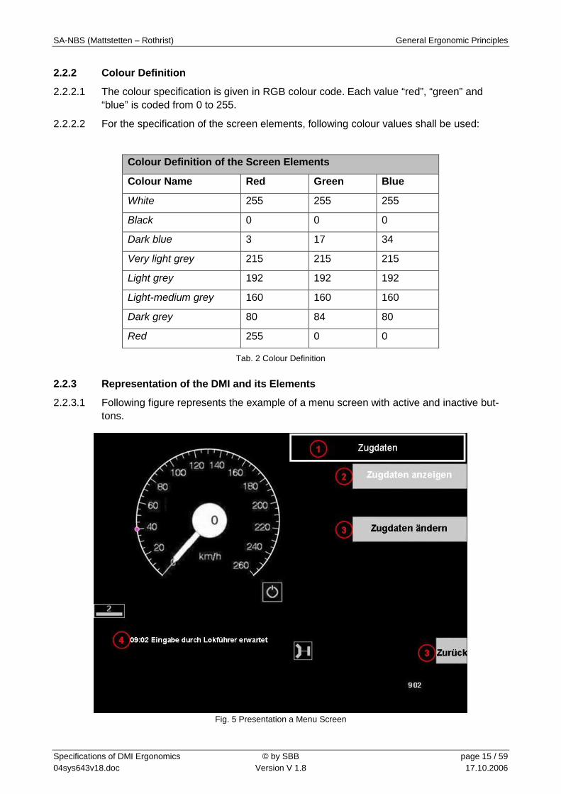
2.2.2.1 The colour specification is given in RGB colour code. Each value “red”, “green” and “blue” is coded from 0 to 255.
2.2.2.2 For the specification of the screen elements, following colour values shall be used:
Colour Definition of the Screen Elements
Colour Name Red Green Blue
White 255 255 255
Black 0 0 0
Dark blue 3 17 34
Very light grey 215 215 215
Light grey 192 192 192
Light-medium grey 160 160 160
Dark grey 80 84 80
Red 255 0 0
Tab. 2 Colour Definition
2.2.3 Representation of the DMI and its Elements
2.2.3.1 Following figure represents the example of a menu screen with active and inactive but-tons.
Fig. 5 Presentation a Menu Screen

SA-NBS (Mattstetten – Rothrist) General Ergonomic Principles
Specifications of DMI Ergonomics © by SBB page 16 / 59 04sys643v18.doc Version V 1.8 17.10.2006
2.2.3.2 The elements displayed on this figure are listed below. The background and font specifi-cations of these elements are defined in Tab. 3 and Tab. 4.
(1) Menu title
(2) “Inactive” button
(3) “Active” buttons
(4) Text message
2.2.3.3 Following figure represents a data entry/modification screen.
Eingabe Zugdaten
Bremsart
Bremsverhältnis
Vmax
Zuglänge
1035
160
R/P
1 2 3 4 5 6 7 8 9 0
350
Bremsart
Bremsverhältnis
Vmax
Zuglänge
R/P
RANGE ERROR
1
23
4
5
6
7
8
9
Fig. 6 Presentation of a Data Entry/Modification Screen
2.2.3.4 The elements displayed on this figure are listed below. The background and font specifi-cations of these elements are defined in Tab. 3 and Tab. 4.
(1) Screen title
(2) Data label
(3) Data entry field (= input field), “not selected/accepted” state
(4) Data entry field (= input field), “not selected/not accepted” state
(5) Data entry field (= input field), “selected/with highlight” state
(6) Data feedback, “accepted” state
(7) Data feedback, “rejected” state
(8) Data feedback, “nominal” state
(9) Numerical PAD

SA-NBS (Mattstetten – Rothrist) General Ergonomic Principles
Specifications of DMI Ergonomics © by SBB page 17 / 59 04sys643v18.doc Version V 1.8 17.10.2006
2.2.3.5 Following figure represents a data confirmation screen.
Fig. 7 Presentation a Data Confirmation Screen
2.2.3.6 The elements displayed on this figure are listed below. The background and font specifi-cations of these elements are defined in Tab. 3 and Tab. 4.
(1) Confirmation screen title
(2) Confirmation request
(3) Data entry field (= input field), “selected/without highlight” state
(4) Data to be validated
(5) “Active” buttons

SA-NBS (Mattstetten – Rothrist) General Ergonomic Principles
Specifications of DMI Ergonomics © by SBB page 18 / 59 04sys643v18.doc Version V 1.8 17.10.2006
2.2.3.7 Following figure represents a data view screen.
Ansicht Zugdaten
R/P G
Bremsart
Bremsverhältnis
Vmax
Zuglänge
R/P
135
160
350
1
2
Fig. 8 Presentation of a Data View Screen
2.2.3.8 The elements displayed on this figure are listed below. The background and font specifi-cations of these elements are defined in Tab. 3 and Tab. 4.
(1) Screen title
(2) Data view
2.2.4 Backgrounds Specification
2.2.4.1 The following table presents the colour that shall be used for both night and day back-grounds of the DMI elements.
Background Specifications
Element Type Night Mode Colour Day Mode Colour
DMI background Black or dark blue1 Light-medium grey
“Active” button background
“Inactive” button background Light grey Dark grey
“Pushed” button background Dark grey Light grey
Screen title background
Menu title background
DMI background DMI background
1 The supplier shall implement two prototypes of DMI, one using the black background and the other with the dark blue background. Tests will then be performed on these prototypes to decide which colour shall be used for the DMI back-ground.

SA-NBS (Mattstetten – Rothrist) General Ergonomic Principles
Specifications of DMI Ergonomics © by SBB page 19 / 59 04sys643v18.doc Version V 1.8 17.10.2006
Background Specifications
Element Type Night Mode Colour Day Mode Colour
Confirmation screen title back-ground
Confirmation request back-ground Dark grey Dark grey
Data to be validated background DMI background DMI background
Data feedback (“echo data”) background DMI background DMI background
Data view background Light grey Dark grey
Text message background DMI background DMI background
Acknowledgement text message background DMI background DMI background
Data label background Dark grey Dark grey
Data entry field2 background
“not selected/not accepted” state
Data entry field background
“not selected/accepted” state
Dark grey Dark grey
Data entry field background
“selected/without highlight” state
Data entry field background
“selected/with highlight” state
Light grey with horizon-tal blue line
Light grey with horizon-tal blue line
Highlight colour Black Black
Numerical PAD (“BK”) back-ground
Alphanumerical PAD (“BK”) background
Light grey Dark grey
Tab. 3 Backgrounds Specifications
2.2.4.2 Shading shall be used to represent elements like buttons, PADs, etc. This shading shall be consistently defined for all softkeys.
2.2.5 Fonts Specification
2.2.5.1 Following fonts shall be used to display text on the DMI.
2 “Data entry field” can be also called “input field”.

SA-NBS (Mattstetten – Rothrist) General Ergonomic Principles
Specifications of DMI Ergonomics © by SBB page 20 / 59 04sys643v18.doc Version V 1.8 17.10.2006
Fonts Specifications
Text Type Font Alignment Night Mode Col-our
Day Mode Colour
“Active” button label
Helvetica
bold
12 pt
Vertically and horizontally centred
Black White
“Inactive” button label
Helvetica
bold
12 pt
Vertically and horizontally centred
White Black
“Pushed” button label
Helvetica
bold
12 pt
Vertically and horizontally centred
Black White
Screen title
Menu title
Confirmation screen title
Helvetica
normal
12 pt
Vertically and horizontally centred
White Dark grey
Confirmation re-quest
Helvetica
normal
14 pt
Vertically cen-tred and aligned right
White White
Data to be vali-dated Helvetica
bold
12 pt
Presentation in a two-column table (see data feedback)
White Dark grey
Data feedback
“nominal” state (data not yet ac-cepted by the driver)
Data label in light grey
No data value
Data label in very light grey
No data value
Data feedback
“accepted” state (data entered and accepted by the driver, data ac-cepted by the EVC)
Helvetica
bold
12 pt
Presentation in a two-column table. The column delimitation shall not be visible.
The first col-umn shall con-tain the data label aligned to the right. The second
Data label in white
Data value in white
Data label in dark grey
Data value in dark grey

SA-NBS (Mattstetten – Rothrist) General Ergonomic Principles
Specifications of DMI Ergonomics © by SBB page 21 / 59 04sys643v18.doc Version V 1.8 17.10.2006
Fonts Specifications
Text Type Font Alignment Night Mode Col-our
Day Mode Colour
Data feedback
“rejected” state (data entered and accepted by the driver, data re-jected by the EVC)
column shall contain the data value aligned to the left.
Data label in white
Data value in white
Data label in dark grey
Data value in dark grey
Data view Helvetica
bold
12 pt
Presentation in a two-column table (see data feedback)
Black White
Text message Helvetica
bold
9 pt
Vertically cen-tred and aligned left
White Dark grey
Acknowledgement text message (with flashing)
Helvetica
bold
9 pt
Vertically and horizontally centred
White Dark grey
Data label Helvetica
normal
14 pt
Vertically cen-tred and aligned right
White White
Data entry field
“not selected/not accepted” state
White White
Data entry field
“not se-lected/accepted” state
White White
Data entry field
“selected/without highlight” state
Black Black
Data entry field
“selected/with highlight” state
Helvetica
bold
18 pt
Vertically cen-tred and aligned left
Light grey Very light grey
Cursor data entry N/A N/A Black Black

SA-NBS (Mattstetten – Rothrist) General Ergonomic Principles
Specifications of DMI Ergonomics © by SBB page 22 / 59 04sys643v18.doc Version V 1.8 17.10.2006
Fonts Specifications
Text Type Font Alignment Night Mode Col-our
Day Mode Colour
Numerical PAD (“BK”)
Helvetica
bold
18 pt
Vertically and horizontally centred
Black White
Alphanumerical PAD (“BK”)
Helvetica
bold
12 pt
Vertically and horizontally centred
Black White
Tab. 4 Fonts Specifications

SA-NBS (Mattstetten – Rothrist) Data Entry Procedure
Specifications of DMI Ergonomics © by SBB page 23 / 59 04sys643v18.doc Version V 1.8 17.10.2006
3 Data Entry Procedure 3.1.1.1 This chapter intends to describe the data entry procedure with a full ETCS application.
This data entry procedure shall be performed in a sequential order and while the train is at standstill.
3.1.1.2 The “common” data entry procedure corresponding to a start of mission in Level 0, UN mode will be presented.
3.1.1.3 Note: the screens representation will not be compliant with the specifications given in the precedent chapter. Otherwise the speed dial and the level and mode indications will be missing also on screen where they shall be displayed. Only the process and naviga-tion are here significant.
3.2 Train and System Start-Up 3.2.1.1 After the driver has switch on the onboard equipment, the system shall perform its self-
tests. At the same time, the driver switches on the driver desk. As soon as the self-tests have been completed, their result shall be indicated to the driver on the DMI.
3.2.1.2 The SB icon shall be displayed on the DMI as soon as the driver desk has been opened and the data entry procedure shall start.
3.2.1.3 The data entry shall automatically start with the display of the driver ID entry screen.
3.2.1.4 The first step to be done by the driver is to enter the ZUB data through the ETCS DMI.
3.3 ZUB Data Entry
3.3.1.1 ZUB data entry shall generally be as specified in Ref. [3].
3.3.1.2 Step 1: No change. The driver presses the “Tools” button corresponding to the technical function menu on top right of the screen.
3.3.1.3 Step 2: No change. The driver selects “ZUB“.
3.3.1.4 Step 3: No change. The driver enters the data and presses the “OK” button. The data are sent to the ZUB.
3.3.1.5 Step 3bis: No change. The accepted data are displayed in white whereas the non-validated data (if any) in red. The driver corrects the wrong data, if any, and presses “OK” again.
3.3.1.6 Step 4: No change. Once all data are accepted, a positive feedback from the ZUB is displayed on the DMI.
3.3.1.7 Step 5: NEW compared to the process defined in Ref [3] – When ZUB has confirmed the data transmission, the “OK” button becomes a “Back” or “Zurück” button.
Fig. 9 deleted
3.3.1.8 The “Zurück“ button shall be used instead of the two “pushes” on the “X“ hard key.
3.3.1.9 When the driver presses on the “Zurück” button, the driver ID entry screen shall be dis-played again and the driver is able to perform the ETCS data entry.

SA-NBS (Mattstetten – Rothrist) Data Entry Procedure
Specifications of DMI Ergonomics © by SBB page 24 / 59 04sys643v18.doc Version V 1.8 17.10.2006
3.4 Start of Mission in Level 0, UN mode
3.4.1.1 Opening the driver desk, the DMI displays by default the text messages, data labels and titles in the language used during the last mission. If the driver wants to change the lan-guage, he shall do it through the technical function menu (using the “tools” button on top right of the screen).
3.4.1.2 As soon as the driver has selected the language and the language selection screen has been closed, the text messages, labels and other captions shall be immediately dis-played in the new selected language.
3.4.1.3 Having changed the default language or not, the driver is first requested to enter his driver ID using following mask.
Fig. 10 Driver ID
3.4.1.4 The driver ID entry shall be located inside the area N as it shall be possible to change this parameter while driving.
3.4.1.5 If the driver wants to change the ID, he has to enter a value or modify the previous one using the keyboard situated in the area BK. The end of the entry shall be indicated by pressing the data entry field itself or the hard key towards this input field. Once one of the entry key has been activated by the driver, the window shall be closed.
SA-NBS (Mattstetten – Rothrist) Data Entry Procedure
Specifications of DMI Ergonomics © by SBB page 25 / 59 04sys643v18.doc Version V 1.8 17.10.2006
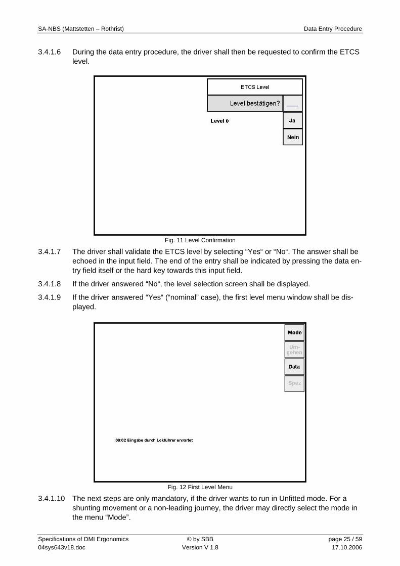
3.4.1.6 During the data entry procedure, the driver shall then be requested to confirm the ETCS level.
Fig. 11 Level Confirmation
3.4.1.7 The driver shall validate the ETCS level by selecting “Yes“ or “No“. The answer shall be echoed in the input field. The end of the entry shall be indicated by pressing the data en-try field itself or the hard key towards this input field.
3.4.1.8 If the driver answered “No“, the level selection screen shall be displayed.
3.4.1.9 If the driver answered “Yes“ (“nominal” case), the first level menu window shall be dis-played.
Fig. 12 First Level Menu
3.4.1.10 The next steps are only mandatory, if the driver wants to run in Unfitted mode. For a shunting movement or a non-leading journey, the driver may directly select the mode in the menu “Mode”.

SA-NBS (Mattstetten – Rothrist) Data Entry Procedure
Specifications of DMI Ergonomics © by SBB page 26 / 59 04sys643v18.doc Version V 1.8 17.10.2006
3.4.1.11 For a normal journey, once the driver has confirmed the ETCS level, he shall enter the train running number. For that he shall select “Data”, the data menu is then displayed.
Daten
Lokführer Daten
Zugnummer
Zugdaten
Level
Zurück
Ändern SR Daten
Fig. 13 Data Menu
3.4.1.12 To access the train running number entry, the driver shall then press on the button “Train Running Number”. Following screen is then displayed.
Fig. 14 Train Running Number
3.4.1.13 The train running number entry shall be located inside the area N as it shall be possible to change this parameter while driving.

SA-NBS (Mattstetten – Rothrist) Data Entry Procedure
Specifications of DMI Ergonomics © by SBB page 27 / 59 04sys643v18.doc Version V 1.8 17.10.2006
3.4.1.14 The driver may abort the train running number entry by selecting the “X” control key. This action shall close the window and displayed the first level menu window. In this case, the value of the train running number shall not be modified.
3.4.1.15 If the driver wants to change the train running number, he has to enter a value or modify the previous one using the keyboard situated in the area BK. The end of the entry shall be indicated by pressing the data entry field itself or the hard key towards this input field. Once one of the entry key has been activated by the driver, the window shall be closed and the first level menu shall be displayed. (See Fig. 12)
3.4.1.16 The driver shall then enter the train data. He shall press the button “train data” on the data menu, the train data menu will then be displayed.
Fig. 15 Train Data Menu
3.4.1.17 To enter or modify the train data, the driver shall select the button “modify train data”, the train data entry screen shall then be displayed.

SA-NBS (Mattstetten – Rothrist) Data Entry Procedure
Specifications of DMI Ergonomics © by SBB page 28 / 59 04sys643v18.doc Version V 1.8 17.10.2006
Bremsart
Eingabe Zugdaten
G R/P
Bremsverhältnis
Vmax
Zuglänge
Bremsart
Bremsverhältnis
Vmax
Zuglänge
Fig. 16 Train Data Entry
3.4.1.18 The train data entry/modification shall cover the area Q as the train data en-try/modification shall only be possible at standstill.
3.4.1.19 The driver may abort the train data entry by selecting the “X” control key. This action shall close the window and displayed the first level menu window. In this case, the train data values shall not be modified.
3.4.1.20 The order of the data to be entered shall be as displayed on. The sequence is defined during the trainborne data preparation so that the driver shall be requested to enter first the “brake type”, the “braking percentage”, the “maximal train speed” and finally the “train length”. Note: If for plausibility test the parameter “train suset” (“Zugreihe”) is used, the button for this parameter shall be added at the top.
3.4.1.21 The train data entry/modification shall follow a full window concept for data entry/change as described in 3.6.5.
3.4.1.22 The data input fields shall be presented within the area N. The data labels and data val-ues which have been accepted by the driver shall be repeated within the area M (data feedback area).
3.4.1.23 The first data to be entered by the driver shall be automatically selected as soon as the train data entry screen is displayed. The driver shall be able to enter or modify the value of the selected data using the dedicated keyboard situated in the area BK. Once he has entered the data, the driver shall accept the entered value by pressing the data entry field itself or the hard key towards this input field. The accepted value shall be echoed within the data feedback area and the next data item of the predefined input sequence shall be selected automatically and its corresponding keyboard shall be displayed.
3.4.1.24 If train data have been already entered and saved into the system and these data are still available, they shall be presented in the data entry fields of the train data entry screen. As a consequence, the driver shall be able to bypass the automatically pro-posed entry sequence and individually select the data he wants to modify.

SA-NBS (Mattstetten – Rothrist) Data Entry Procedure
Specifications of DMI Ergonomics © by SBB page 29 / 59 04sys643v18.doc Version V 1.8 17.10.2006
3.4.1.25 There shall be a maximum of 5 data to be entered on one window. If more than one window have to be used to enter the train data, it shall be possible to navigate between the windows using “previous” and “next” keys. These keys shall be activated according to the position of the current page in the window sequence.
3.4.1.26 If there are more than 5 data to be entered and as a consequence several windows are used for the train data entry, the data feedback area shall present the whole set of data label belonging to the train data entry.
3.4.1.27 Once all values have been entered and accepted by both the driver and the system, a “End” button shall appear on the screen as follow.
R/PBremsart
Eingabe Zugdaten
135Bremsverhältnis
160Vmax
350Zuglänge
Bremsart
Bremsverhältnis
Vmax
Zuglänge
Ende
R/P
135
160
350
Fig. 17 Train Data Entry, “End“ Button
3.4.1.28 Using the “End“ button, the train data are sent to the EVC and an additional plausibility check may occur at this step of the procedure.
3.4.1.29 If the train data have been correctly entered and checked, the driver will be requested to confirm the entered train data with following screen.

SA-NBS (Mattstetten – Rothrist) Data Entry Procedure
Specifications of DMI Ergonomics © by SBB page 30 / 59 04sys643v18.doc Version V 1.8 17.10.2006
Fig. 18 Train Data Confirmation
3.4.1.30 In a full window concept for data entry/modification, the train data confirmation shall cover the area Q.
3.4.1.31 The data items and values, the driver has to confirm, shall be presented within the area M, corresponding to the data feedback area of the train data entry.
3.4.1.32 The driver shall be requested to confirm the entered train data by selecting “Yes” or “No”. The answer shall be echoed in the input field. The end of the entry shall be indi-cated by pressing the data entry field itself or the hard key towards this input field.
3.4.1.33 If the driver answers “Yes“, then once the entry has been ended by the driver using the data entry field or the hard key towards it, the window shall be closed and the first level menu window shall be displayed (See Fig. 12).
3.4.1.34 If the driver answers “No“, then once the entry has been ended by the driver using the data entry field or the hard key towards it, the window shall be closed and the train data entry/modification screen (see Fig. 17) shall be displayed with the just entered values. If the driver does not agree with the presented values, he shall be able to select directly the data value(s) he wants to change. The selection of the data value shall be done by selecting the data entry field itself or the function key towards the corresponding value. It shall not be necessary to enter all values again. Pressing on “OK”, the driver shall then again be requested to confirm the values.
3.4.1.35 Once all train data values have been accepted and confirmed by the driver, the first level menu window shall be displayed (See Fig. 12). The data entry is then completed and the driver is now able to start.

SA-NBS (Mattstetten – Rothrist) Data Entry Procedure
Specifications of DMI Ergonomics © by SBB page 31 / 59 04sys643v18.doc Version V 1.8 17.10.2006
3.4.1.36 In order to start a mission in Unfitted mode, the driver shall select the “Mode” button on the first level menu, the following screen will then be displayed.
Fig. 19 Mode Menu
3.4.1.37 Remark: As soon as the driver has selected “Mode” and the mode menu has been dis-played, the text message with ID 83 (see Ref. [2]) shall disappear from the list of text messages.
3.4.1.38 To run in Unfitted mode, the driver shall press on the “Start“ button. Once he has se-lected “Start”, the mode menu shall be closed, the first level menu shall be displayed and the driver shall be requested to confirm the UN mode by means of a text message to be acknowledged.
3.4.1.39 Once the driver has acknowledged the Unfitted mode, the train shall be ready to start its journey.
3.5 Data Modification 3.5.1.1 When all data necessary for a journey have been entered and validated, the driver shall
be able to modify them if needed. For this he shall use the data menu (see Tab. 5 for more details).
3.5.1.2 The driver ID, train running number and language may be changed at standstill or while running, whereas the modification of all other data shall only be possible at standstill.
3.5.1.3 If the driver wants to change a data after the data entry procedure, the already stored values shall be presented to him.

SA-NBS (Mattstetten – Rothrist) Data Entry Procedure
Specifications of DMI Ergonomics © by SBB page 32 / 59 04sys643v18.doc Version V 1.8 17.10.2006
3.6 General Principles on Data Entry/Modification Procedure
3.6.1 Structure of Data Entry/Modification Menu (informative)
3.6.1.1 Following table presents the ETCS menu used to enter/modify the necessary data, start a mission and modify the track conditions.
First Level Button Name
Key Second Level Button Name
Key Third Level Button Name
Key
Mode F1 Start F2 Shunting F3 Shunting Exit F4 Non-Leading F5 Non-Leading Exit F6 Suppress F2 Override EOA F2 Override route
unsuitability check F3 Override loading gauge F3
Data F3 Driver data F2 Driver ID F2 Language F4 Train running number F3 Train data F4 View F2 Modify F4 ERTMS/ETCS Level F5 Level 0 F2 Level 1 F3 Level 2 F4 Staff responsible data F6 Special F4 Track ahead free F3 Slippery track F4 Slippery F2 Non slippery F4 Show supervision data F5 Show geographical
position F6
Tab. 5 Menu Structure
3.6.1.2 This table is only given as information, the official specification shall be found in Ref. [2].
3.6.2 Navigation Keys
3.6.2.1 The following hard keys are used for navigation:
The “X” hard key, also called [Close] button (Ref. [6] 4.4.2.7.1): used to close the current screen, abort the data entry and return to the first level menu window. This key shall always be active except during the automatic data entry initiated by the trainborne system at start-up (e.g. driver ID entry, RBC data entry, etc.). It shall also not be available when a confirmation screen is displayed (e.g. train data confirmation request) as the driver shall be forced to answer with “Yes” or “No”.
The “arrow-up” and “arrow-down” hard keys, also called [Up or Down] button (Ref. [6] 4.4.2.7.1): used to scroll within a list of text messages or a list of predefined val-ues for the data entry (e.g. language selection)
3.6.2.2 There shall be two soft keys, when relevant, for navigation:
A [Next] button (Ref. [6] 4.4.2.7.1): used to select the next window within the train ata entry, if more than 5 parameters shall be entered.

SA-NBS (Mattstetten – Rothrist) Data Entry Procedure
Specifications of DMI Ergonomics © by SBB page 33 / 59 04sys643v18.doc Version V 1.8 17.10.2006
A [Previous] button (Ref. [6] 4.4.2.7.1): used to select the previous window within the train data entry, if more than 5 parameters shall be entered, or to return to a higher menu level.
3.6.3 Input of Data
3.6.3.1 There are two types of data to be entered by the driver:
Free data
Pre-defined data
3.6.3.2 For free data entry, a numerical or alphanumerical keyboard shall be presented to the driver. This (alpha)numerical keyboard shall be displayed in the area BK of the DMI screen. It shall be an arrangement of at least 11 buttons: a set of either numbers or characters depending on the keyboard type and a “delete” button labelled with “ ”.
3.6.3.3 For pre-defined data entry, two solutions are possible depending on the amount of input possibilities.
3.6.3.4 In cases the choice for input data is limited: “R/P” or “G”, “Level 0” or “Level 1” or “Level 2”, etc., the keyboard layout shall be used and the pre-defined choices are presented as a data key label into the area BK.
3.6.3.5 If the key of an input value is defined over several BKs because of the wording length, it shall be possible to activate this soft key with all covered hard keys.
3.6.3.6 In cases the amount or type of possibilities can not fit into a keyboard representation, the input possibilities shall be presented in a vertical scrollable list into the area N. A keyboard composed of an “arrow-up” key and if possible, depending of the type of hardware, an “arrow-down” shall be associated to this scrollable list. For a touch device, the driver shall be able to select the desired value either using the scrolling keys or us-ing the soft key and its associated hard key.
3.6.3.7 According to these principles, the brake type and level selection shall use a keyboard implemented as defined in following tables Tab. 6 and Tab. 7.
Brake Type Covered Area
G BK1 + BK2
R/P BK3 + BK4
Tab. 6 “Brake Type” Keyboard
Level Covered Area
Level 0 BK1 + BK2
Level 1 BK3 + BK4
Level 2 BK5 + BK6
Tab. 7 “Level” Keyboard

SA-NBS (Mattstetten – Rothrist) Data Entry Procedure
Specifications of DMI Ergonomics © by SBB page 34 / 59 04sys643v18.doc Version V 1.8 17.10.2006
3.6.3.8 Following figure presents the level selection as it shall be implemented.
Fig. 20 Level Selection
3.6.3.9 The language selection shall occur through an endless scrollable vertical list.
3.6.4 Data Entry Screen Closing
3.6.4.1 Generally after the driver has entered a value in a data entry field, he shall press the entry field or its associated hard key in order to accept the given value, this corresponds to an [Enter] button (Ref. [6] 4.4.2.7.1).
3.6.4.2 If there is only one data to be entered on the screen (driver ID entry, train running num-ber entry, level selection, language selection, data confirmation), the window shall be automatically closed and, if relevant, the data confirmation screen shall be displayed. If no confirmation is requested, once the [Enter] button has been pressed, the first level menu shall be displayed.
3.6.4.3 If there is more than one data to be entered during train data entry, the next data item of the predefined input sequence shall be selected automatically and its corresponding keyboard shall be displayed. Once all data have been individually accepted by the driver, an “accept all” button (here labelled with “Ende”) shall be displayed on the screen. It corresponds to an [Enter all] button (Ref. [6] 4.4.2.7.1) and its function is to start the consistency check (if any) and – in case of successful check – to close the data entry screen. As soon as the data entry screen is closed, the data confirmation screen shall be presented.
3.6.4.4 As there is more than one data to be entered during RBC data entry, the next data item of the predefined input sequence shall be selected automatically and its corresponding keyboard shall be displayed. As there is no consistency check required for the RBC data entry, there shall be no “accept all” button.
3.6.5 Concept of Full Window for Data Entry/Modification
3.6.5.1 The train data entry and the RBC data entry shall follow this concept.

SA-NBS (Mattstetten – Rothrist) Data Entry Procedure
Specifications of DMI Ergonomics © by SBB page 35 / 59 04sys643v18.doc Version V 1.8 17.10.2006
3.6.5.2 This concept for data entry shall be used to enter data, which are safety relevant and as a consequence which require great attention from the driver. With this concept, the driver receives a good feedback of which values have been taken into account by the trainborne system.
3.6.5.3 The area Q shall be used for this type of data entry/modification. As the whole DMI screen (with the exception of the text message area) is covered by this kind of data en-try/modification, the speed dial, level and mode icons shall be omitted.
3.6.5.4 A screen using the full window concept is composed of three elements, which shall be implemented as specified in Tab. 3 and Tab. 4:
A window title located at the top of the area N.
An input fields area situated within the area N.
A data feedback area presented within the area M.
Fig. 21 Full Window for Data Entry/Modification
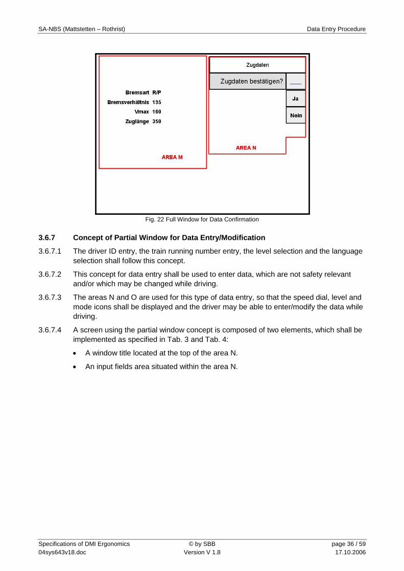
3.6.6 Concept of Full Window for Data Confirmation
3.6.6.1 The train data confirmation and RBC data confirmation shall follow this concept.
3.6.6.2 This concept shall be used to confirm data which are safety relevant and which are: ei-ther data saved into the system that must be validated again by the driver, or data en-tered using a full window concept, that have to be confirmed after the entry.
3.6.6.3 The area Q shall be used for this type of data confirmation. As the whole DMI screen (with the exception of the text message area) is covered by this kind of data confirma-tion, the speed dial, level and mode icons shall be omitted.
3.6.6.4 Three elements, which shall be implemented as specified in Tab. 3 and Tab. 4 are com-posing the confirmation screen:
A window title located at the top of the area N.
A validation request situated within the area N.
An area, where the data to be validated are displayed, presented within the area M.
SA-NBS (Mattstetten – Rothrist) Data Entry Procedure
Specifications of DMI Ergonomics © by SBB page 36 / 59 04sys643v18.doc Version V 1.8 17.10.2006
Fig. 22 Full Window for Data Confirmation
3.6.7 Concept of Partial Window for Data Entry/Modification
3.6.7.1 The driver ID entry, the train running number entry, the level selection and the language selection shall follow this concept.
3.6.7.2 This concept for data entry shall be used to enter data, which are not safety relevant and/or which may be changed while driving.
3.6.7.3 The areas N and O are used for this type of data entry, so that the speed dial, level and mode icons shall be displayed and the driver may be able to enter/modify the data while driving.
3.6.7.4 A screen using the partial window concept is composed of two elements, which shall be implemented as specified in Tab. 3 and Tab. 4:
A window title located at the top of the area N.
An input fields area situated within the area N.

SA-NBS (Mattstetten – Rothrist) Data Entry Procedure
Specifications of DMI Ergonomics © by SBB page 37 / 59 04sys643v18.doc Version V 1.8 17.10.2006
Fig. 23 Partial Window for Data Entry/Modification
3.6.8 Partial Window for Data Confirmation
3.6.8.1 The level confirmation shall follow this concept.
3.6.8.2 This concept shall be used to confirm data which are not safety relevant and which are: either data saved into the system that must be validated again by the driver, or data en-tered using a partial window concept, that have to be confirmed after the entry.
3.6.8.3 The areas N and O are used fort his type of data confirmation.
3.6.8.4 Three elements, which shall be implemented as specified in Tab. 3 and Tab. 4 are com-posing the confirmation screen:
A window title located at the top of the area N.
A validation request situated within the area N.
An area, where the data to be validated are displayed, presented within the area N.
Fig. 24 Partial Window for Data Confirmaiton

SA-NBS (Mattstetten – Rothrist) Data Entry Procedure
Specifications of DMI Ergonomics © by SBB page 38 / 59 04sys643v18.doc Version V 1.8 17.10.2006
3.6.9 Data Confirmation Window
3.6.9.1 If entered values have to be confirmed in a full or partial window concept, the data con-firmation procedure shall use two steps to confirm the data. These two steps shall use at least two different key positions.
3.6.9.2 The two confirmation steps are:
First step: the driver shall confirm the presented data values using a “Yes” or “No” button. The “Yes”/”No” answer shall be echoed in the input field.
Second step: the driver shall accept the “Yes”/”No” answer by pressing the data en-try field itself or the hard key towards this input field.
3.6.9.3 “Yes” and “No” shall be the only keys available on the DMI. The “X“ and the “Tool” hard key shall not be active during a data confirmation process as the driver shall be forced to answer with “Yes“ or “No“.
3.6.10 Sequence of the Data in Train Data Entry
3.6.10.1 The train data shall be displayed according to following order (see Fig. 16):
Brake type
Braking percentage
Maximal train speed
Train length
3.6.10.2 If a plausibility check of the train data is implemented (out of scope of this specification), a new parameter “train subset” shall be added on the top of the parameters list.
3.6.11 Menu Closing
3.6.11.1 As soon as the driver presses following buttons, the action associated to the button shall be executed and the first level menu shall be automatically displayed:
“Start” in menu “Mode” (close menu “Mode”)
“Shunting” in menu “Mode” (close menu “Mode”)
“Exit Shunting” in menu “Mode” (close menu “Mode”)
“Non-Leading” in menu “Mode” (close menu “Mode”)
“Exit Non-Leading” in menu “Mode” (close menu “Mode”)
“Slippery” in menu “Special/Slippery track” (close menu “Special”)
“Non slippery” in menu “Special/Slippery track” (close menu “Special”)
“Show supervision data” in menu “Special” (close menu “Special”)
“Show geographical position” in menu “Special” (close menu “Special”)

SA-NBS (Mattstetten – Rothrist) Driving Information
Specifications of DMI Ergonomics © by SBB page 39 / 59 04sys643v18.doc Version V 1.8 17.10.2006
4 Driving Information 4.1 Speed and Supervision Information 4.1.1.1 Speed and Supervision information shall be displayed into the areas A (for supervised
distance information), B (for speed information), C (for supplementary driving informa-tion) and E – only the left side – (for monitoring).
4.1.1.2 The main elements of the speed and supervision areas are presented in following figure.
Fig. 25 Elements of Speed and Supervision Areas
4.1.1.3 The elements on this figure are not compliant with these specification, only the wording is here relevant.
4.1.2 Supervision Limits
4.1.2.1 The speed limits described in this chapter shall be calculated for the Ceiling Speed Monitoring (CSM) and the Target Speed Monitoring (TSM). Only a subset of these limits shall be used for the Release Speed Monitoring (RSM). By comparing the train speed and location to the defined supervision limits, the trainborne system shall generate indi-cations to the driver and braking actions.
4.1.2.2 The permitted speed (VPerm) is the speed the driver is requested to follow. This speed shall be indicated to the driver. When the current train speed (VTrain) is lower or equal to this permitted speed, No Status (NoS) is active as no supervision limit has been ex-ceeded.
4.1.2.3 If the train speed exceeds the permitted speed, the Over-speed Status (OvS) is then activated and the driver informed.
4.1.2.4 If the train speed exceeds the warning limit, the trainborne system activates a Warning Status (WaS) allowing the driver to avoid the brake intervention. After the warning has been triggered, it shall remain active until the train speed is equal or below the permitted speed.
4.1.2.5 If the train speed exceeds the intervention limit, the trainborne system activates the In-tervention Status (IntS), the brakes are applied. The Intervention Status information overwrites the Over-speed Status information and the Warning Status information.

SA-NBS (Mattstetten – Rothrist) Driving Information
Specifications of DMI Ergonomics © by SBB page 40 / 59 04sys643v18.doc Version V 1.8 17.10.2006
4.1.3 Speed Monitoring
4.1.3.1 The Ceiling Speed Monitoring (CSM) applies to a section where the permitted speed is constant, defined by the current value of the most restrictive speed profile. The No Sta-tus, Over-Speed Status, Warning Status and Intervention Status are available for the Ceiling Speed Monitoring.
4.1.3.2 The Target Speed Monitoring (TSM) applies when a speed target has been defined on a section or a point in front of the train. The No Status, Over-Speed Status, Warning Sta-tus and Intervention Status are also available for the Target Speed Monitoring, but two more status have been defined for this monitoring:
The first status is the Indication Status (IndS) represented on the planning area by the Brake Curve Area Starting Point (see 4.2.8). The location of this status shall be defined so that the driver has enough time to reduce the train speed before the per-mitted speed starts to decrease.
In addition to this Indication Status, a Pre-indication Status (PreS) shall be available. It shall be activated as soon as the new target speed is known.
4.1.3.3 The Release Speed Monitoring (RSM) applies only to the section near an EoA where the speed is monitored against a constant value, the release speed.
4.1.3.4 Following figure illustrates the supervision limits and speed monitoring.
Fig. 26 Supervision Limits and Speed Monitoring
4.1.4 Colour Definition
4.1.4.1 Following colour codes shall be used to display the speed and supervision information.
160
100
90
Geschwindigkeit [km/h]
Weg [km]
TIP TIP DPSvL
EOA
20
0
50
100 150
200
250
92
0
50
100 150
200
250
140
0
50
100 150
200
250
150
0
50
100 150
200
250
150
0
50
100 150
200
250
75
0
50
100 150
200
250
48
20
0
50
100 150
200
250
150
0
50
100 150
200
250
15
20
SA-NBS (Mattstetten – Rothrist) Driving Information
Specifications of DMI Ergonomics © by SBB page 41 / 59 04sys643v18.doc Version V 1.8 17.10.2006
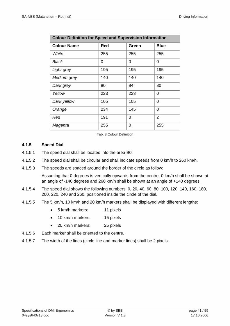
Colour Definition for Speed and Supervision Information
Colour Name Red Green Blue
White 255 255 255
Black 0 0 0
Light grey 195 195 195
Medium grey 140 140 140
Dark grey 80 84 80
Yellow 223 223 0
Dark yellow 105 105 0
Orange 234 145 0
Red 191 0 2
Magenta 255 0 255
Tab. 8 Colour Definition
4.1.5 Speed Dial
4.1.5.1 The speed dial shall be located into the area B0.
4.1.5.2 The speed dial shall be circular and shall indicate speeds from 0 km/h to 260 km/h.
4.1.5.3 The speeds are spaced around the border of the circle as follow:
Assuming that 0 degrees is vertically upwards from the centre, 0 km/h shall be shown at an angle of -140 degrees and 260 km/h shall be shown at an angle of +140 degrees.
4.1.5.4 The speed dial shows the following numbers: 0, 20, 40, 60, 80, 100, 120, 140, 160, 180, 200, 220, 240 and 260, positioned inside the circle of the dial.
4.1.5.5 The 5 km/h, 10 km/h and 20 km/h markers shall be displayed with different lengths:
5 km/h markers: 11 pixels
10 km/h markers: 15 pixels
20 km/h markers: 25 pixels
4.1.5.6 Each marker shall be oriented to the centre.
4.1.5.7 The width of the lines (circle line and marker lines) shall be 2 pixels.

SA-NBS (Mattstetten – Rothrist) Driving Information
Specifications of DMI Ergonomics © by SBB page 42 / 59 04sys643v18.doc Version V 1.8 17.10.2006
4.1.5.8 The speed scale numbers shall be displayed in Helvetica 15 pixels.
Fig. 27 Speed Dial with 260 km/h Scale
4.1.6 Current Train Speed Pointer
4.1.6.1 The current train speed pointer shall be displayed in the area B1.
4.1.6.2 It consists of a needle and a circular centre point. Both parts always have the same col-our.
4.1.6.3 The pointer indicates a speed between 0 and 260 km/h according to the speed dial. The needle shall point at the value of the current train speed in the speed dial while the circu-lar centre point shall display this current speed in digits.
4.1.6.4 The digital value of the current speed shall be displayed in 17 pixels high Helvetica characters.
Fig. 28 Current train speed pointer (dimensions are in pixels)

SA-NBS (Mattstetten – Rothrist) Driving Information
Specifications of DMI Ergonomics © by SBB page 43 / 59 04sys643v18.doc Version V 1.8 17.10.2006
4.1.6.5 The colour of the current train speed pointer shall be implemented as follow.
Pointer between
0km/h – VPerm
Pointer between
0km/h – VTarget
Pointer between
VTarget – VPerm
Pointer between
VPerm – VInt
If VTrain > VPerm
NoS white N/A N/A N/A
OvS N/A N/A N/A orange
WaS N/A N/A N/A orange
CSM
IntS N/A N/A N/A red
PreS white N/A N/A N/A
IndS N/A white yellow N/A
OvS N/A white yellow orange
WaS N/A white yellow orange
TSM
IntS N/A white yellow red
NoS white N/A N/A N/A RSM
IntS red N/A N/A N/A
NoS white N/A N/A N/A
IndS white N/A N/A N/A
OvS white N/A N/A N/A
WaS white N/A N/A N/A
NoFS
IntS white N/A N/A N/A
N/A = not applicable
Tab. 9 Colour Specification of Current Train Speed Pointer
4.1.7 Circular Speed Gauge (CSG)
4.1.7.1 The circular speed gauge shall be situated around the speed dial and shall display in-formation related to the permitted speed VPerm, the target speed VTarget, the intervention speed VInt and the release speed VRelease.
4.1.7.2 The circular speed gauge shall be placed along the outside border of the speed dial from -145 degrees to +145 degrees (depending on speeds information).
4.1.7.3 The size of the circular speed gauge shall be according to following figure.

SA-NBS (Mattstetten – Rothrist) Driving Information
Specifications of DMI Ergonomics © by SBB page 44 / 59 04sys643v18.doc Version V 1.8 17.10.2006
Fig. 29 Circular Speed Gauge Dimensions (in pixels)
4.1.7.4 The colour of the circular speed gauge shall be implemented according to following ta-ble.
CSG between
0km/h – VPerm
CSG between
0km/h – VTarget
CSG between
VTarget – VPerm
CSG between
VPerm – VInt
If VTrain > VPerm
NoS Medium grey N/A N/A N/A
OvS Medium grey N/A N/A orange
WaS Medium grey N/A N/A orange
CSM
IntS Medium grey N/A N/A red
PreS N/A medium grey light grey N/A
IndS N/A medium grey Yellow (vtrain > vtarget)
Light grey (vtrain ≤ vtarget)
N/A
OvS N/A medium grey yellow orange
WaS N/A medium grey yellow orange
TSM
IntS N/A medium grey yellow red
NoS Yellow/dark yel-low
N/A N/A N/A RSM
IntS red N/A N/A N/A
NoFS AllS N/A N/A N/A N/A
N/A = not applicable
Tab. 10 Colour Specification of Circular Speed Gauge

SA-NBS (Mattstetten – Rothrist) Driving Information
Specifications of DMI Ergonomics © by SBB page 45 / 59 04sys643v18.doc Version V 1.8 17.10.2006
4.1.8 Release Speed
4.1.8.1 The release speed, when applicable, shall be displayed under the form of a speed gau-ge along the outside board of the speed dial and under a digital form into the area B6.
4.1.8.2 The size of the release speed gauge inside the circular speed gauge is 5 pixels and its colour is dark yellow. The remaining part of the circular speed gauge shall be used to show the permitted speed (3 pixels in yellow). The two gauges (release speed gauge and permitted speed gauge) shall be separated by a 1-pixel line in the DMI background colour.
4.1.8.3 The digital value of the release speed shall be displayed in dark yellow and in 17 pixels high Helvetica characters.
Fig. 30 Display of Release Speed (fonts and ticks are not compliant with these specifications)
4.1.8.4 The release speed indication shall remain visible whilst the related EoA is valid.
4.1.9 Set Speed Indicator
4.1.9.1 The set speed indicator shall be displayed in the area B2.
4.1.9.2 The set speed indicator shall be implemented as shown in the next figure.
“Set Speed Indicator” Specifications
Size: 14x14 pixels Colours: magenta centre white inner circle black outer circle The area around the black circle shall be transparent.
Fig. 31 “Set Speed Indicator“ Specifications
Remark: Speed dial representation is not compliant with these specifications

SA-NBS (Mattstetten – Rothrist) Driving Information
Specifications of DMI Ergonomics © by SBB page 46 / 59 04sys643v18.doc Version V 1.8 17.10.2006
4.1.10 Distance to Target
4.1.10.1 The distance to target shall be displayed into the area A2.
4.1.10.2 The distance to target shall be displayed according to following table.
Distance to target
CSM AllS no
PreS no
IndS yes
OvS yes
WaS yes
TSM
IntS yes
NoS tbd RSM3
IntS tbd
NoFS AllS no (except SR and OS on driver’s request)
Tab. 11 Conditions for Display of the Distance to Target
4.1.11 Warning Time to Intervention
4.1.11.1 The warning time to intervention shall be displayed in the area A1.
4.1.11.2 It shall be implemented as specified in Ref. [7] 6.2.2.2 and using the colour of Tab. 8.
4.1.12 Display of Icons in the “Actual Orders Area”
4.1.12.1 No sound shall be generated when a new information regarding track conditions like “non-stopping area” is displayed within the “actual orders area”.
4.1.13 Geographical Position
4.1.13.1 The geographical position shall be displayed on request by the driver (through action on specific button, see Tab. 5) under the form of a text message inside the area Eleft.
3 This shall be defined at UNISIG level, action 828

SA-NBS (Mattstetten – Rothrist) Driving Information
Specifications of DMI Ergonomics © by SBB page 47 / 59 04sys643v18.doc Version V 1.8 17.10.2006
4.2 Planning Information
4.2.1.1 The planning information shall be displayed in the area D.
4.2.1.2 The main elements of the planning area are presented in following figure.
Fig. 32 Elements of Planning Area
4.2.2 Colour Definition
4.2.2.1 Following colour codes shall be used to display the planning information.
Colour Definition for Planning Information
Colour Name Red Green Blue
White 255 255 255
Black 0 0 0
Light grey 192 192 192
Medium grey 150 150 150
Dark grey 80 84 80
Yellow 255 255 0
Green 0 255 0
Red 255 0 0
Light blue 102 102 255
Blue 0 0 204
Tab. 12 Colour Definition

SA-NBS (Mattstetten – Rothrist) Driving Information
Specifications of DMI Ergonomics © by SBB page 48 / 59 04sys643v18.doc Version V 1.8 17.10.2006
4.2.3 Speed Profile
4.2.3.1 The colours of the planning area shall be defined as follow:
Speed Profile Specifications
Element Night Mode Colour Day Mode Colour
Profile Background Blue Blue
Profile Foreground Light blue Light blue
Tab. 13 Speed Profile Specifications
4.2.4 Distance Scale
4.2.4.1 The distance scale (lines and km) shall be displayed as follow:
Distance Scale Specifications
Night Mode Colour Day Mode Colour
Light grey Dark grey
Tab. 14 Distance Scale Specifications
4.2.4.2 The 0 m line and the 500 m line shall be emphasised.
4.2.4.3 There should be at least 7 ranges available for the distance scale: from 0 to 500 m, from 0 to 1 000 m, from 0 to 2 000 m, from 0 to 4 000 m, from 0 to 8 000 m, from 0 to 16 000 m and from 0 to 32 000 m.
4.2.4.4 The default range for the first display of the planning area shall be from 0 to 8 000 m.
4.2.5 Gradient Profile
4.2.5.1 Gradient per mils shall be displayed in “Helvetica normal 8 pt” font within the gradient profile area. The colours for the gradient profile area shall be implemented as follow:
Day/Night Mode Gradient Rectangle Colour Digits Colour Sign
Downhill gradient Medium grey White - Night mode
Uphill gradient Light grey Black +
Downhill gradient Dark grey White - Day mode
Uphill gradient Light grey Black +
Tab. 15 Gradient Profile Specifications
SA-NBS (Mattstetten – Rothrist) Driving Information
Specifications of DMI Ergonomics © by SBB page 49 / 59 04sys643v18.doc Version V 1.8 17.10.2006
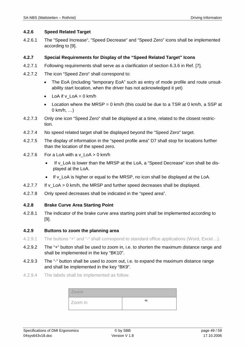
4.2.6 Speed Related Target
4.2.6.1 The “Speed Increase“, “Speed Decrease“ and “Speed Zero” icons shall be implemented according to [9].
4.2.7 Special Requirements for Display of the “Speed Related Target” Icons
4.2.7.1 Following requirements shall serve as a clarification of section 6.3.6 in Ref. [7].
4.2.7.2 The icon “Speed Zero“ shall correspond to:
The EoA (including “temporary EoA” such as entry of mode profile and route unsuit-ability start location, when the driver has not acknowledged it yet)
LoA if v_LoA = 0 km/h
Location where the MRSP = 0 km/h (this could be due to a TSR at 0 km/h, a SSP at 0 km/h, …)
4.2.7.3 Only one icon “Speed Zero“ shall be displayed at a time, related to the closest restric-tion.
4.2.7.4 No speed related target shall be displayed beyond the “Speed Zero” target.
4.2.7.5 The display of information in the “speed profile area” D7 shall stop for locations further than the location of the speed zero.
4.2.7.6 For a LoA with a v_LoA > 0 km/h
If v_LoA is lower than the MRSP at the LoA, a “Speed Decrease” icon shall be dis-played at the LoA.
If v_LoA is higher or equal to the MRSP, no icon shall be displayed at the LoA.
4.2.7.7 If v_LoA > 0 km/h, the MRSP and further speed decreases shall be displayed.
4.2.7.8 Only speed decreases shall be indicated in the “speed area”.
4.2.8 Brake Curve Area Starting Point
4.2.8.1 The indicator of the brake curve area starting point shall be implemented according to [9].
4.2.9 Buttons to zoom the planning area
4.2.9.1 The buttons “+“ and “-“ shall correspond to standard office applications (Word, Excel…).
4.2.9.2 The “+“ button shall be used to zoom in, i.e. to shorten the maximum distance range and shall be implemented in the key “BK10”.
4.2.9.3 The “-“ button shall be used to zoom out, i.e. to expand the maximum distance range and shall be implemented in the key “BK9”.
4.2.9.4 The labels shall be implemented as follow.
Zoom
Zoom in

SA-NBS (Mattstetten – Rothrist) Driving Information
Specifications of DMI Ergonomics © by SBB page 50 / 59 04sys643v18.doc Version V 1.8 17.10.2006
Zoom out
Tab. 16 Zoom
4.2.10 Display of Icons in the “Actual Order Area”
4.2.10.1 No sound shall be generated when a new information regarding track conditions like “non-stopping area” is displayed within the “actual order area”.

SA-NBS (Mattstetten – Rothrist) Symbols (informative)
Specifications of DMI Ergonomics © by SBB page 51 / 59 04sys643v18.doc Version V 1.8 17.10.2006
5 Symbols (informative) 5.1.1.1 This chapter is only given as information, the official specification shall be found in Ref.
[2].
5.1.1.2 In the project SA-NBS, the TIU implementation does not support some functions such as door status, pantograph status etc. Such icons will be indicated with “no TIU info”
5.1.1.3 Due to EVC configuration, the orders shown on the area B3/4/5 shall be shown without anticipation and with manual action by the driver. These icons are indicated with “no an-ticipation” and “manual action”, respectively. Note that the orders are announced on the planning area.
5.2 Monitor Symbols
Monitor Symbols
Symbol Description
Emergency brake intervention
Service brake intervention
No icon Emergency brake applied
No icon Service brake applied
Level 0
Level 1
Level 2
Level 3
Level STM with continuous air gap transmission
Level STM with discontinuous air gap transmission
No TIU info TIU status: doors open
No TIU info TIU status: doors closed

SA-NBS (Mattstetten – Rothrist) Symbols (informative)
Specifications of DMI Ergonomics © by SBB page 52 / 59 04sys643v18.doc Version V 1.8 17.10.2006
Monitor Symbols
Symbol Description
No TIU info TIU status: pantograph raised
No TIU info TIU status: pantograph lowered
No TIU info TIU status: main switch off
No TIU info TIU status: main switch on
Slippery function activated
Emergency stop
Tab. 17 Monitor Symbols
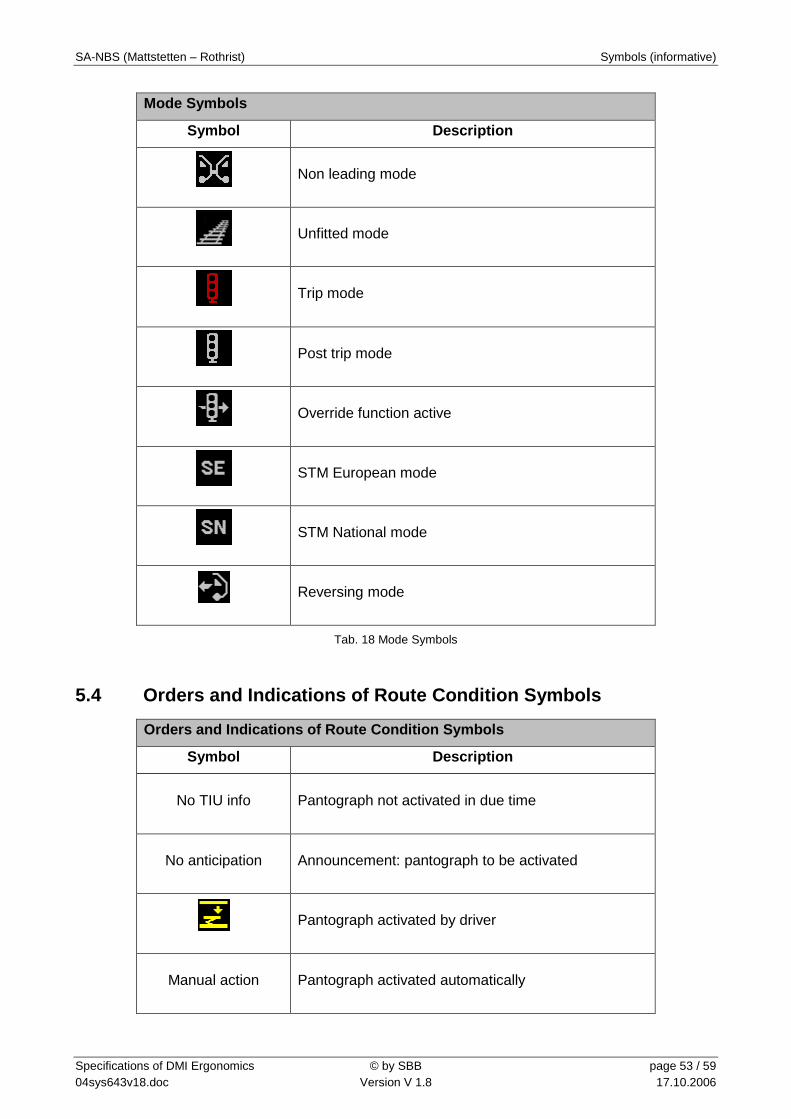
5.3 Mode Symbols
Mode Symbols
Symbol Description
Stand-by mode
Shunting mode
Full supervision mode
Staff responsible mode
On-sight mode
SA-NBS (Mattstetten – Rothrist) Symbols (informative)
Specifications of DMI Ergonomics © by SBB page 53 / 59 04sys643v18.doc Version V 1.8 17.10.2006
Mode Symbols
Symbol Description
Non leading mode
Unfitted mode
Trip mode
Post trip mode
Override function active
STM European mode
STM National mode
Reversing mode
Tab. 18 Mode Symbols
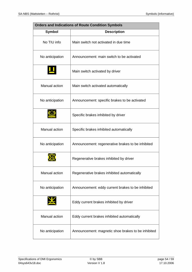
5.4 Orders and Indications of Route Condition Symbols
Orders and Indications of Route Condition Symbols
Symbol Description
No TIU info Pantograph not activated in due time
No anticipation Announcement: pantograph to be activated
Pantograph activated by driver
Manual action Pantograph activated automatically
SA-NBS (Mattstetten – Rothrist) Symbols (informative)
Specifications of DMI Ergonomics © by SBB page 54 / 59 04sys643v18.doc Version V 1.8 17.10.2006
Orders and Indications of Route Condition Symbols
Symbol Description
No TIU info Main switch not activated in due time
No anticipation Announcement: main switch to be activated
Main switch activated by driver
Manual action Main switch activated automatically
No anticipation Announcement: specific brakes to be activated
Specific brakes inhibited by driver
Manual action Specific brakes inhibited automatically
No anticipation Announcement: regenerative brakes to be inhibited
Regenerative brakes inhibited by driver
Manual action Regenerative brakes inhibited automatically
No anticipation Announcement: eddy current brakes to be inhibited
Eddy current brakes inhibited by driver
Manual action Eddy current brakes inhibited automatically
No anticipation Announcement: magnetic shoe brakes to be inhibited
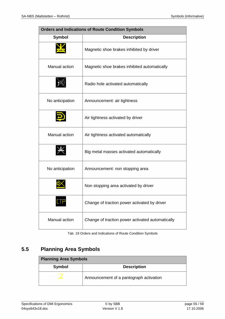
SA-NBS (Mattstetten – Rothrist) Symbols (informative)
Specifications of DMI Ergonomics © by SBB page 55 / 59 04sys643v18.doc Version V 1.8 17.10.2006
Orders and Indications of Route Condition Symbols
Symbol Description
Magnetic shoe brakes inhibited by driver
Manual action Magnetic shoe brakes inhibited automatically
Radio hole activated automatically
No anticipation Announcement: air tightness
Air tightness activated by driver
Manual action Air tightness activated automatically
Big metal masses activated automatically
No anticipation Announcement: non stopping area
Non stopping area activated by driver
Change of traction power activated by driver
Manual action Change of traction power activated automatically
Tab. 19 Orders and Indications of Route Condition Symbols
5.5 Planning Area Symbols
Planning Area Symbols
Symbol Description
Announcement of a pantograph activation

SA-NBS (Mattstetten – Rothrist) Symbols (informative)
Specifications of DMI Ergonomics © by SBB page 56 / 59 04sys643v18.doc Version V 1.8 17.10.2006
Planning Area Symbols
Symbol Description
Announcement of a radio hole
Announcement of air tightness
Announcement of a regenerative brakes inhibition
Announcement of a eddy current brakes inhibition
Announcement of a magnetic shoe brakes inhibition
Announcement of a powerless section that requires main switch activation
Announcement of a big metal mass that requires automatic balise antenna switch off
Speed increase
Speed decrease
Speed decrease, stop target
Brake curve area starting point
Announcement of a non stopping area (tunnel, bridge, etc.)
Announcement of a change of traction power
Tab. 20 Planing Area Symbols
5.6 GSM-R Radio Communication Symbols
GSM-R Radio Communication Symbols
Symbol Description
Opening connection
Connection established

SA-NBS (Mattstetten – Rothrist) Symbols (informative)
Specifications of DMI Ergonomics © by SBB page 57 / 59 04sys643v18.doc Version V 1.8 17.10.2006
No connection, connection lost
Tab. 21 GSM-R Radio Communication Symbols

SA-NBS (Mattstetten – Rothrist) Data Entry Performance Specification
Specifications of DMI Ergonomics © by SBB page 58 / 59 04sys643v18.doc Version V 1.8 17.10.2006
6 Data Entry Performance Specification 6.1 Start of Mission for SH Movement 6.1.1.1 The duration of a SoM for a mission in SH shall be 25 s (50%), 30 s (95%).
6.1.1.2 It includes: All necessary steps for ETCS.
6.1.1.3 Precondition: The EVC is in SB and was before in NP or SH.
6.1.1.4 The start of this time interval shall be: EVC is ready for train data entry (i.e. self-tests are completed).
6.1.1.5 The end of this interval shall be: EVC is in SH mode.
6.2 Start of Mission for Train Movement I
6.2.1.1 The duration of a SoM for a mission in UN shall be 100 s (50%), 120 s (95%).
6.2.1.2 It includes: Entry of ZUB data including train running number; all necessary steps for ETCS; entry of train running number on cab radio (if not exchanged with ETCS DMI).
6.2.1.3 Precondition: The EVC is in SB and was before in NP or SH.
6.2.1.4 The start of the time interval shall be: EVC is ready for train data entry (i.e. self-tests are completed).
6.2.1.5 The end of the time interval shall be: EVC is in UN mode and ZUB data is accepted.
6.3 Start of Mission for Train Movement II 6.3.1.1 The duration of a SoM for a mission in UN shall be 70 s (50%), 85 s (95%).
6.3.1.2 It includes: Validation of ZUB data; entry of train running number in ZUB screen; all nec-essary steps for ETCS (with new driver ID and new train running number); entry of train running number on cab radio (if not exchanged with ETCS DMI).
6.3.1.3 Precondition: The train is in SB and was before in UN (no SH or NP in between).
6.3.1.4 The start of the time interval shall be: EVC is ready for train data entry (i.e. cab is open).
6.3.1.5 The end of the time interval shall be: EVC is in UN mode and ZUB data is accepted.
6.4 Change of Data
6.4.1.1 The duration of changing/revalidating some data in UN shall be 30 s (50%), 35 s (95%).
6.4.1.2 It includes: Check of ZUB data; check of train data for ETCS; entry of new driver ID.
6.4.1.3 Precondition: The train is in UN.
6.4.1.4 The start of the time interval shall be: EVC is ready for train data entry (i.e. at standstill).
6.4.1.5 The end of the time interval shall be: Train is in UN, new data is accepted.
6.5 General Remark
6.5.1.1 The validation of the requirements above shall be done with a sample of fully trained drivers and at least one month experience with ETCS.

SA-NBS (Mattstetten – Rothrist) Documentation Requirements
Specifications of DMI Ergonomics © by SBB page 59 / 59 04sys643v18.doc Version V 1.8 17.10.2006
7 Documentation Requirements 7.1.1.1 The supplier shall upgrade the document dealing with the DMI specifications.
7.1.1.2 The supplier shall completely describe the navigation through the screens of the data entry and start of mission procedures. This description shall be done using a prototype on PC (software-tool with full implemented state machine).
7.1.1.3 The part of the Alstom DMI specifications describing the navigation through the screens shall be non-proprietary.