nbs® cuscinetti rullini - needle bearings(1.7.12)
DESCRIPTION
ÂTRANSCRIPT
RODAMIENTOS DE AGUJASNEEDLE BEARINGS
CATÁLOGO TÉCNICO GENERALGENERAL TECHNICAL CATALOGUE
01.07.12
Política ambientalEl presente Catálogo Técnico NBS® ha sido realizado con material ecológico certificado FSC.El proceso productivo del papel se lleva a cabo respetando las normativas vigentes. DS/EN ISO 14001 e ISO 9001:2008.La plastificación de la portada se realizó utilizando material biodegradable; las tintas para la impresión son de base vegetal.Por favor continúe Usted también con su compromiso por la protección del medio ambiente.
Environmental policyThis NBS® Technical Catalogue has been produced with 100% ecological material certified FSC.Manufacturing process follows the regulations in force: DS/EN ISO 14001 and ISO 9001:2008. Plasticization of the cover page has been achieved using biodegradable materials, inks used are vegetable based. Please continue your actions in order to protect the environment and recycle properly.
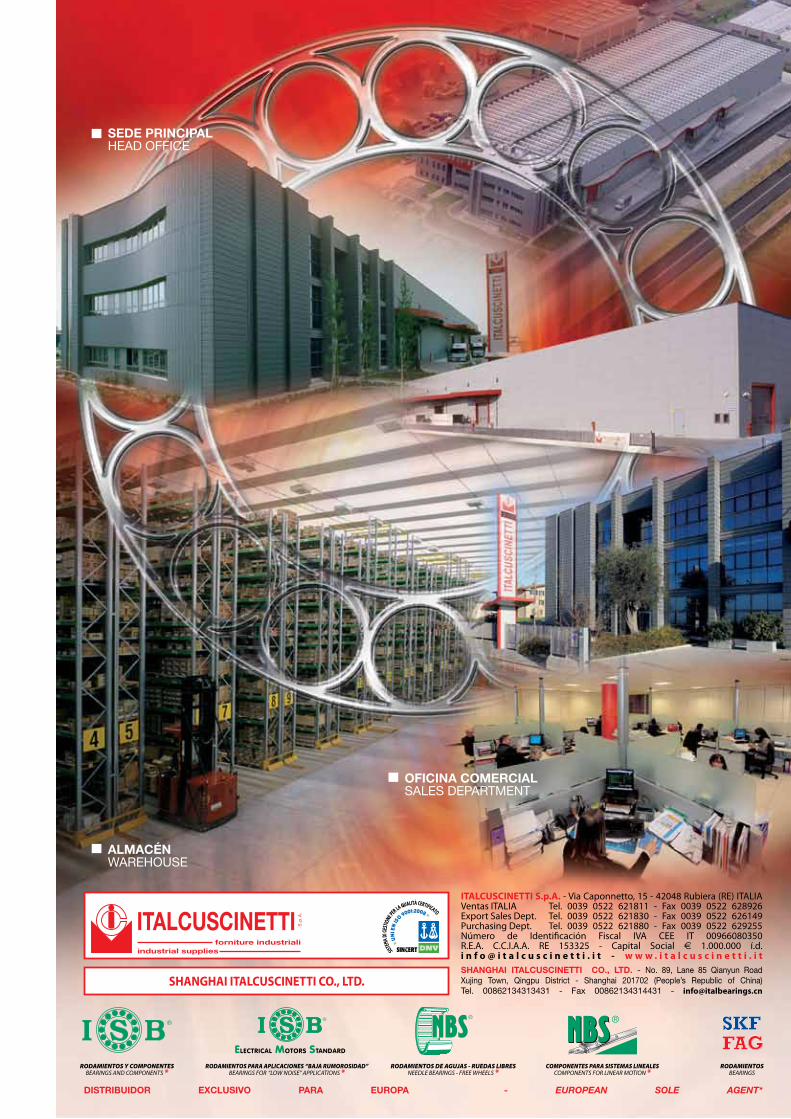
SEDE PRINCIPALHEAD OFFICE
ALMACÉNWAREHOUSE
OFICINA COMERCIALSALES DEPARTMENT
DISTRIBUIDOR EXCLUSIVO PARA EUROPA - EUROPEAN SOLE AGENT*
RODAMIENTOS DE AGUJAS - RUEDAS LIBRESNEEDLE BEARINGS - FREE WHEELS *
COMPONENTES PARA SISTEMAS LINEALESCOMPONENTS FOR LINEAR MOTION *
RODAMIENTOSBEARINGS
SHANGHAI ITALCUSCINETTI CO., LTD. - No. 89, Lane 85 Qianyun Road Xujing Town, Qingpu District - Shanghai 201702 (People’s Republic of China)Tel. 00862134313431 - Fax 00862134314431 - [email protected]
ITALCUSCINETTIforniture industriali
industrial supplies
S.p
.A.
SHANGHAI ITALCUSCINETTI CO., LTD.
ITALCUSCINETTI S.p.A. - Via Caponnetto, 15 - 42048 Rubiera (RE) ITALIAVentas ITALIA Tel. 0039 0522 621811 - Fax 0039 0522 628926Export Sales Dept. Tel. 0039 0522 621830 - Fax 0039 0522 626149Purchasing Dept. Tel. 0039 0522 621880 - Fax 0039 0522 629255Número de Identificación Fiscal IVA CEE IT 00966080350R.E.A. C.C.I.A.A. RE 153325 - Capital Social € 1.000.000 í.d.i n f o @ i t a l c u s c i n e t t i . i t - w w w . i t a l c u s c i n e t t i . i t
RODAMIENTOS Y COMPONENTESBEARINGS AND COMPONENTS *
RODAMIENTOS PARA APLICACIONES “BAJA RUMOROSIDAD”BEARINGS FOR “LOW NOISE” APPLICATIONS *
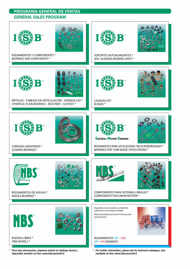
PROGRAMA GENERAL DE VENTAS GENERAL SALES PROGRAM
* Para más información, rogamos solicite el catálogo técnico, disponible también on-line: www.italcuscinetti.it
* For further information, please ask for technical catalogue, also available on line: www.italcuscinetti.it
RODAMIENTOS SKF - FAGSKF - FAG BEARINGS
Disponible un stock amplio y completo de rodamientos con entrega inmediata.
Wide and complete assortment of bearings with prompt delivery.
RUEDAS LIBRES *FREE WHEELS *
RODAMIENTOS PARA APLICACIONES “BAJA RUMOROSIDAD” *BEARINGS FOR “LOW NOISE” APPLICATIONS *
CASQUILLOS*BUSHES *
CORONAS GIRATORIAS *SLEWING BEARINGS *
���
COMPONENTES PARA SISTEMAS LINEALES*COMPONENTS FOR LINEAR MOTION *
RODAMIENTOS Y COMPONENTES *BEARINGS AND COMPONENTS *
RODAMIENTOS DE AGUJAS *NEEDLE BEARINGS *
SOPORTES AUTOALINEANTES *SELF-ALIGNING BEARING UNITS *
RÓTULAS - CABEZAS DE ARTICULACIÓN - HORQUILLAS *SPHERICAL PLAIN BEARINGS - ROD ENDS - CLEVISES *
ElEctrical Motors standard

CATÁLOGO TÉCNICO GENERALGENERAL TECHNICAL CATALOGUE
Distribuidor / Distributor

*hora legal (período de marzo a octubre en Italia) hora solar (-1) para las capitales con el horario indicado en rojo no existe una hora legal
*summer time (from March to October in Italy) standard time (-1) time is indicated in red for capitals with no daylight saving time (DST)
9
58
40
1
67
19
68
12
43
15
70
63
62
41
53
20
16
13
72
748
3
10
47
212
3235
59
27
31
30 51
44 6423
562234
36
69
18
4952 54
55
8
25
57160
17
3728
5733
39
65
466
24
6150
PAÍSES DONDE ESTAMOS PRESENTESCOUNTRIES WHERE WE ARE REPRESENTED

29
11
42
66
38
2614
4
45
1
2
3
4
5
6
7
8
9
10
11
12
13
14
15
16
17
18
19
20
21
22
23
24
25
26
27
28
29
30
31
32
33
34
35
36
37
38
39
40
41
42
43
44
45
46
47
48
49
50
51
52
53
54
55
56
57
58
59
60
61
62
63
64
65
66
67
68
69
70
71
72
ARGELIA (Argel - 11:00)
ARABIA SAUDITA (Riyadh - 13:00)
ARGENTINA (Buenos Aires - 07:00)
AUSTRALIA (Canberra - 20:00)
AUSTRIA (Viena - 12:00)
BÉLGICA (Bruselas - 12:00)
BRASIL (Brasilia - 07:00)
BULGARIA (Sofía - 13:00)
CANADÁ (Ottawa - 06:00)
CHILE (Santiago - 06:00)
CHINA (Pekín - 18:00)
CHIPRE (Nicosia -13:00 )
COLOMBIA (Bogotá - 05:00)
COREA DEL SUR (Seúl - 19:00)
COSTA DE MARFIL (Abidjan - 10:00)
COSTA RICA (San José - 04:00)
CROACIA (Zagreb- 12:00)
DINAMARCA (Copenhague - 12:00)
EGIPTO (El Cairo - 13:00)
EL SALVADOR (San Salvador - 04:00)
EMIRADOS ÁRABES UNIDOS (Abu Dhabi - 14:00)
ESTONIA (Tallinn - 13:00)
FINLANDIA (Helsinki - 13:00)
FRANCIA (París - 12:00)
ALEMANIA (Berlín - 12:00)
JAPÓN (Tokio - 19:00)
JORDANIA (Amman - 13:00)
GRECIA (Atenas - 13:00)
INDIA (Nueva Delhi - 15:30)
IRLANDA (Dublín - 11:00)
ISLANDIA (Reykjavik - 10:00)
ISRAEL (Jerusalén - 13:00)
ITALIA (Roma - 12:00)*
LETONIA (Riga - 13:00)
LIBANO (Beirut - 13:00)
LITUANIA (Vilnius - 13:00)
MACEDONIA (Skopie - 12:00)
MALASIA (Kuala Lumpur - 18:00)
MALTA (Valletta - 12:00)
MARRUECOS (Rabat - 10:00)
MÉXICO (Ciudad de México - 06:00)
NEPAL (Kathmandú - 15:45)
NIGERIA (Abuja - 11:00)
NORUEGA (Oslo - 12:00)
NUEVA ZELANDIA (Wellington - 22:00)
HOLANDA (Ámsterdam - 12:00)
PAQUISTÁN (Islamabad - 16:00)
PERÚ (Lima - 05:00)
POLONIA (Varsovia - 12:00)
PORTUGAL (Lisboa - 11:00)
REINO UNIDO (Londres - 11:00)
REPUB. CHECA (Praga - 12:00)
REPUB. DOMINICANA (Santo Domingo - 06:00)
REPUB. ESLOVACA (Bratislava - 12:00)
RUMANÍA (Bucarest - 13:00)
RUSIA (Moscú - 14:00)
SAN MARINO (San Marino - 12:00)
SENEGAL (Dakar - 10:00)
SIRIA (Damasco - 13:00)
ESLOVENIA (Liubliana - 12:00)
ESPAÑA (Madrid - 12:00)
ESTADOS UNIDOS DE AMÉRICA (Washington - 06:00)
SUDÁFRICA (Pretoria - 12:00)
SUECIA (Estocolmo - 12:00)
SUIZA (Berna - 12:00)
TAIWAN (Taipei - 18:00)
TUNISIA (Túnez - 11:00)
TURQUÍA (Ankara - 13:00)
UCRAINA (Kiev - 13:00)
UGANDA (Kampala - 14:00)
HUNGRÍA (Budapest - 12:00)
VENEZUELA (Caracas - 06:00)
ALGERIA
SAUDI ARABIA
ARGENTINA
AUSTRALIA
AUSTRIA
BELGIUM
BRAZIL
BULGARIA
CANADA
CHILE
CHINA
CYPRUS
COLOMBIA
SOUTH KOREA
IVORY COAST
COSTA RICA
CROATIA
DENMARK
EGYPT
EL SALVADOR
UNITED ARAB EMIRATES
ESTONIA
FINLAND
FRANCE
GERMANY
JAPAN
JORDAN
GREECE
INDIA
IRELAND
ICELAND
ISRAEL
ITALY
LATVIA
LEBANON
LITHUANIA
MACEDONIA
MALAYSIA
MALTA
MOROCCO
MEXICO
NEPAL
NIGERIA
NORWAY
NEW ZEALAND
NETHERLANDS
PAKISTAN
PERU
POLAND
PORTUGAL
UNITED KINGDOM
CZECH REPUBLIC
DOMINICAN REPUBLIC
SLOVAKIAN REPUBLIC
RUMANIA
RUSSIA
SAN MARINO
SENEGAL
SYRIA
SLOVENIA
SPAIN
UNITED STATES OF AMERICA
SOUTH AFRICA
SWEDEN
SWITZERLAND
TAIWAN
TUNISIA
TURKEY
UKRAINE
REPUBLIC OF UGANDA
HUNGARY
VENEZUELA
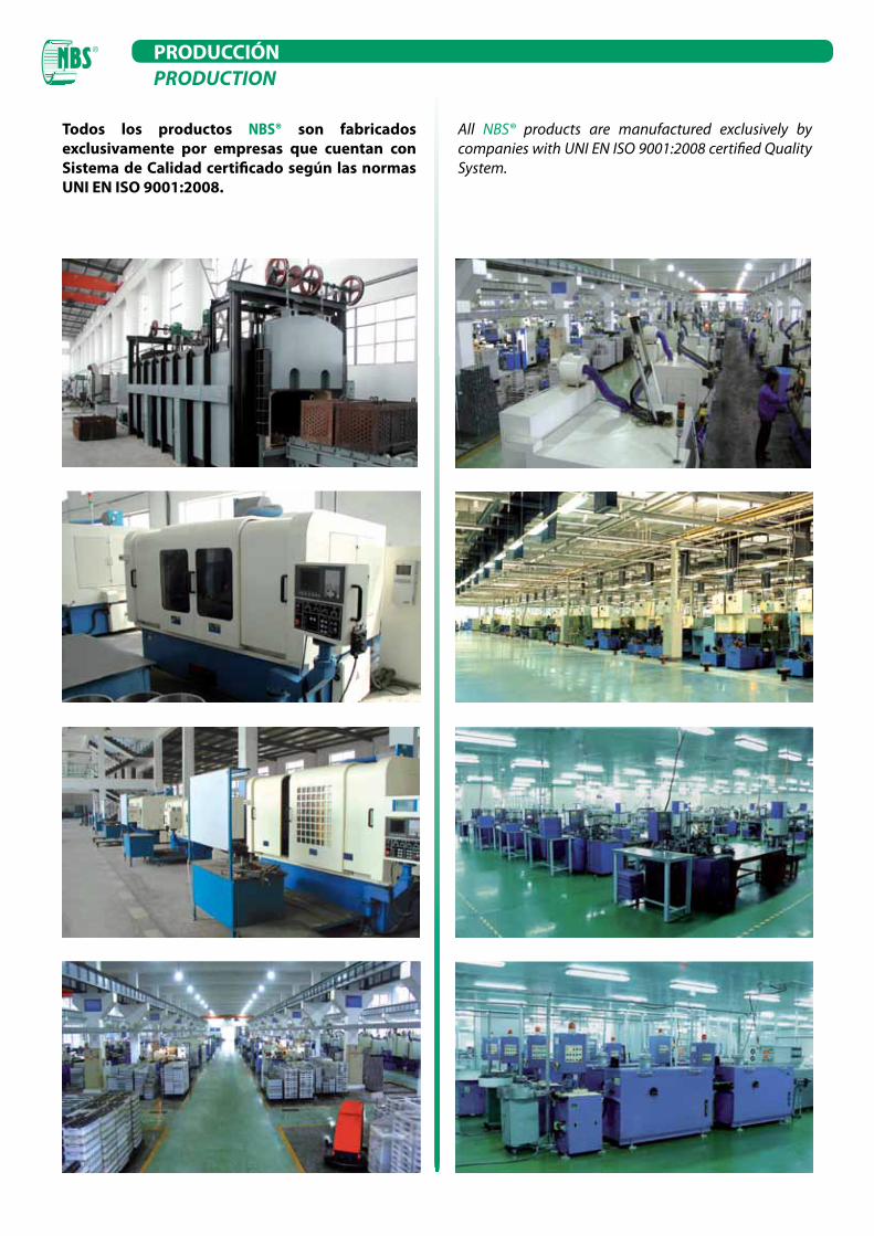
Todos los productos NBS® son fabricados exclusivamente por empresas que cuentan con Sistema de Calidad certificado según las normas UNI EN ISO 9001:2008.
All NBS® products are manufactured exclusively by companies with UNI EN ISO 9001:2008 certified Quality System.
PRODUCCIÓNPRODUCTION
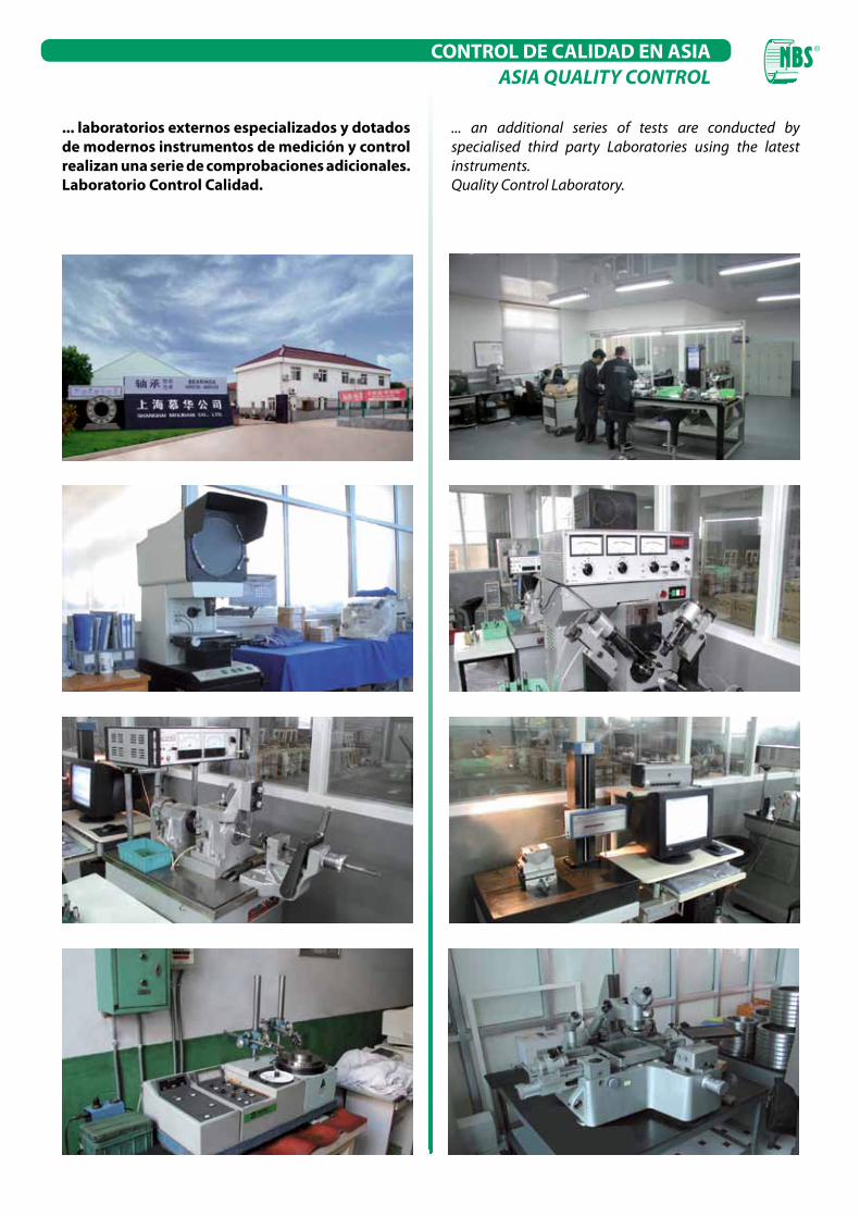
... laboratorios externos especializados y dotados de modernos instrumentos de medición y control realizan una serie de comprobaciones adicionales.Laboratorio Control Calidad.
... an additional series of tests are conducted by specialised third party Laboratories using the latest instruments.Quality Control Laboratory.
CONTROL DE CALIDAD EN ASIAASIA QUALITY CONTROL
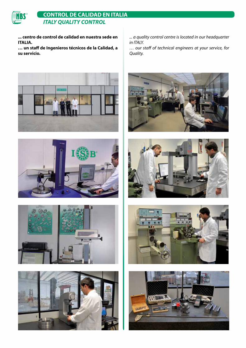
... centro de control de calidad en nuestra sede en ITALIA.… un staff de Ingenieros técnicos de la Calidad, a su servicio.
... a quality control centre is located in our headquarter in ITALY.… our staff of technical engineers at your service, for Quality.
CONTROL DE CALIDAD EN ITALIAITALY QUALITY CONTROL
INNER RING
ROLLER / SPHERE 61 ÷ 64
OUTER RING59 ÷ 63
MAX
MIN
MAX72.000
MIN71.987
0.010
0.010
0.025
MAX
MIN
MAX22.000
MIN21.880
0.025
F
L
M
H
E
0.63
0.15
D
0.20
CB
Brand Type
Gr. Material Grade Pcs.
A
62011
List
a di
strib
uzio
ne
VERI
FICA
TO D
A ap
prov
ed b
y
N°Pagina
Page
1 di of
04/0
8/09
CON
TRO
LLO
EFF
ETTU
ATO
DA:
Nam
e of
Ins
pect
or
na
na
B
C
na
na
7067
VIB
RA
TIO
N
(μm
/s)
nana
BEARING TESTING
REPORT
STANDARD
3
Via Caponnetto, 15 - 42048 Rubiera (RE) ITALIA
Tel. 0039 0522621880 - Fax 0039 0522629255
[email protected] - www.italcuscinetti.it
ITEM
BAR CODE
25700700
F Material composition
OIL or GREASE
BallsCage
material
Inner ring material Outer ring material
E
Contact surface (roller / race)
(BLUE OF PRUSSIA)
free upper surface (mm)
contact area (mm)
free lower surface (mm)
na
0.149
0.061
na
D
RO
UG
HN
ESS
Ra
(µm
)
inner bore
na
roller / sphere
0.132
outer race
0.193
inner race
na
VCs (mm)
0.0050.003
δCs (mm)
21.94321.943
21.94321.943
VBs (mm)
nanana
nanana
δBs (mm)
RADIAL CLEARANCE Gr (*)
0.0350.055
RU
NN
ING
AC
CU
RA
CY
(mm
)
Kea
0.0060.003Kia
nana
Sd
nana
0.003
Sea
nanaSia
nana
VDmp
0.0070.003
VDp
0.00671.998
71.99671.99871.996
na
na
δDs
na
na
na
DIM
ENSI
ON
S PR
ECIS
ION
(mm
)
δds
na
na
Vdp
na
Vdmp
Supplier 4 Supplier 5
AHARDNESS
(HRC)
808003107090
Slovakia
95 D11
61.559.5
61
1 + 1
na
RILEVAZIONI Testing Value
NBSINA
Supplier 3
62
N.B
.L.
I.
outer ring
0.287
NOISE (dB) (**)
na
N.B
.
DATA
Ales
sand
ro B
arbi
eri
L.I.
FORNITORE
Supplier name
NBS - INA
DATA CONTROLLO Testing
DENOMINAZIONE
Part Name
APRECISIONE
ccuracy
PN (standard)
Cuscinetto a rullini NKS 55
QTA' CONTROLLATA
Inspected Quantity:
04 Febbraio 2011
0.191
Mod 6.1.1 rev. 4
F
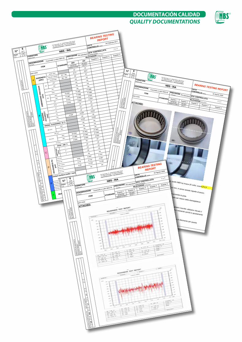
Il cuscinetto INA ha 24 rullini, aventi Ø 5 x 16.7 mm di lunghezza; quello NBS ha invece 25 rullini, aventi Ø 5.5
per 17.6 mm di lunghezza. ( 23 rullini, aventi Ø 5.5 17,6
E
Il valore di rugosità è stato preso su una lunghezza di misura pari a 6 mm, in senso assiale rispetto al pezzo,
con un valore di cut-off pari a 0.25 mm x 5. Nella pagina successiva vengono riportati i grafici delle misurazioni di enrambe le piste.
D
Il cuscinetto INA, non disponendo di particolare barcode, viene identificato per mezzo della stampigliatura
posta sul suo anello esterno.C
(*) Non essendo possibile effettuare una prova specifica per il rilievo del diametro inscritto, abbiamo rilevato il
gioco radiale residuo, posizionando i cuscinetti su una spina avente Ø 54,98 e valutando quindi lo spostamento
radiale complessivo.
B
(**) Il valore di rumorosità ha semplice scopo comparativo, non esistendo tabelle di riferimento per questa
tipologia di cuscinetto.
A
62009
List
a di
strib
uzio
ne
VERI
FICA
TO D
A ap
prov
ed b
y:
Page 2
Sig.
ZAN
ASI
(UD
OR)
di of
95 D11
RILEVAZIONI Testing ValueSupplier 3 Supplier 4Supplier 5
25700700
FORNITORE Supplier name
NBS - INA
ATTACHED:
Supplier 1 Supplier 2808003107090
Slovakia
ITEMBAR CODE
DATA CONTROLLO Testing
DENOMINAZIONE Part Name
Accuracy PN (standard)
Cuscinetto a rullini NKS 55
QTA' CONTROLLATA Inspected Quantity:
04 Agosto 2009
1 + 1N
.B.
N.B
.L.
I.L.
I.
COMMENTS:
N°
BEARING TESTING REPORT
STANDARD
3
Pagina
DAT
A
Ales
sand
ro B
arbi
eri
04/0
8/09
CON
TRO
LLO
EFF
ETTU
ATO
DA:
N
ame
of I
nspe
ctor
Mod 6.1.1 rev. 4
PRECISIONE
Via Caponnetto, 15 - 42048 Rubiera (RE) ITALIA
Tel. 0039 0522621880 - Fax 0039 0522629255
[email protected] - www.italcuscinetti.it F
ED
CB
A
L.I.
L.I.
N.B
.N
.B.
CON
TRO
LLO
EFF
ETTU
ATO
DA:
N
ame
of I
nspe
ctor
ATTACHED:
VERI
FICA
TO D
A ap
prov
ed b
y:
Ales
sand
ro B
arbi
eri
04/0
8/09
DAT
A
BAR CODE
25700700Slovakia
808003107090 95 D11STANDARD
RILEVAZIONI Testing Value
Supplier 1 Supplier 2 Supplier 3 Supplier 4 Supplier 5
DENOMINAZIONE
Part Name
Cuscinetto a rullini NKS 55 Accuracy
PN (standard) QTA' CONTROLLATA
Inspected Quantity:
1 + 1
ITEM
List
a di
strib
uzio
ne
Sig.
ZAN
ASI
(UD
OR)
FORNITORE
Supplier name
NBS - INA
DATA CONTROLLO Testing
BEARING TESTING
REPORT04 Agosto 2009
2009
Pagina 3di of
3
Page
N°6
Mod 6.1.1 rev. 4
PRECISIONE
Via Caponnetto, 15 - 42048 Rubiera (RE) ITALIA
Tel. 0039 0522621880 - Fax 0039 0522629255
[email protected] - www.italcuscinetti.it
DOCUMENTACIÓN CALIDADQUALITY DOCUMENTATIONS
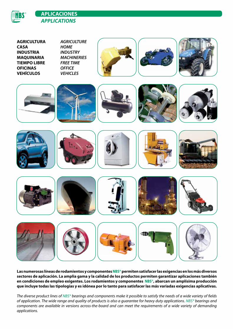
AGRICULTURA AGRICULTURECASA HOMEINDUSTRIA INDUSTRYMAQUINARIA MACHINERIESTIEMPO LIBRE FREE TIMEOFICINAS OFFICEVEHÍCULOS VEHICLES
Las numerosas líneas de rodamientos y componentes NBS® permiten satisfacer las exigencias en los más diversos sectores de aplicación. La amplia gama y la calidad de los productos permiten garantizar aplicaciones también en condiciones de empleo exigentes. Los rodamientos y componentes NBS®, abarcan un amplísima producción que incluye todas las tipologías y es idónea por lo tanto para satisfacer las más variadas exigencias aplicativas.
The diverse product lines of NBS® bearings and components make it possible to satisfy the needs of a wide variety of fields of application. The wide range and quality of products is also a guarantee for heavy duty applications. NBS® bearings and components are available in versions across-the-board and can meet the requirements of a wide variety of demanding applications.
APLICACIONESAPPLICATIONS

CATÁLOGO TÉCNICO GENERALGENERAL TECHNICAL CATALOGUE
2
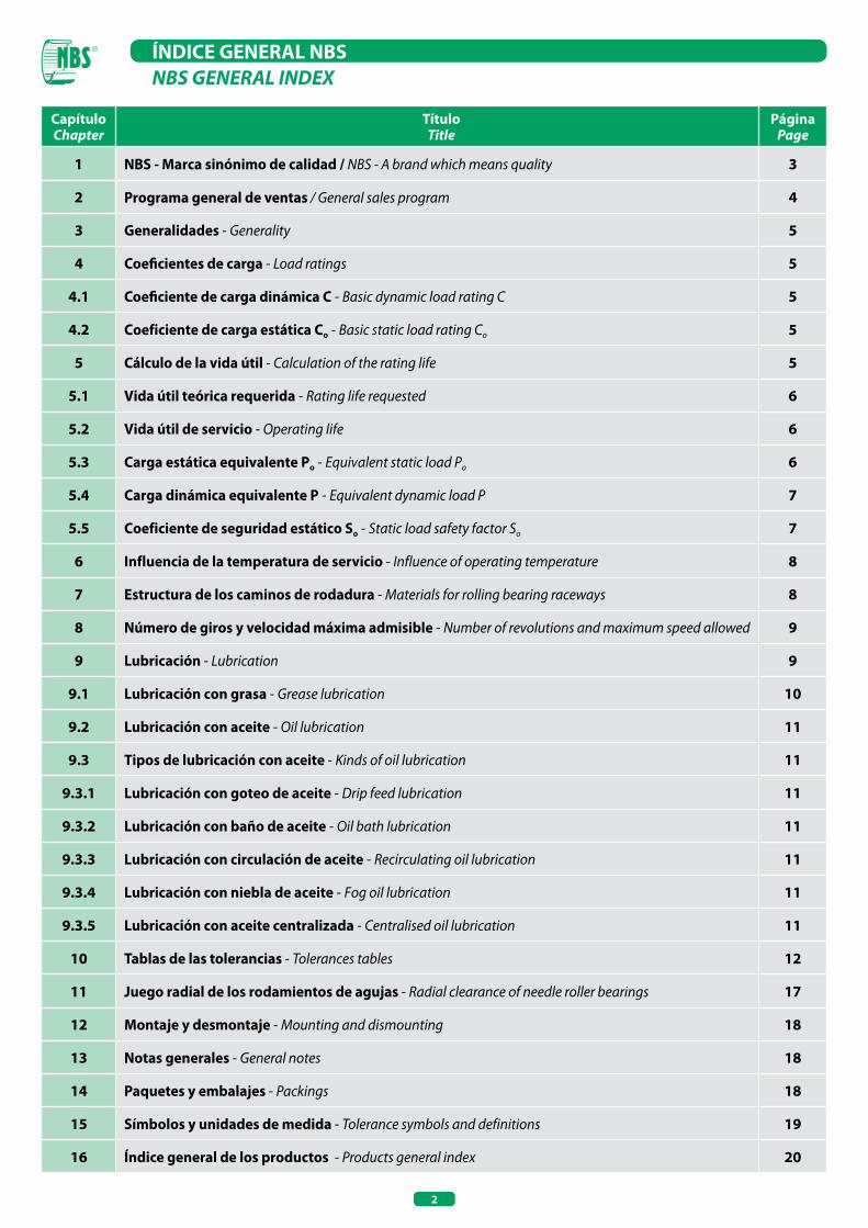
ÍNDICE GENERAL NBS
Programa general de ventas- General
sales program
CapítuloChapter
TítuloTitle
PáginaPage
1 NBS - Marca sinónimo de calidad / NBS - A brand which means quality 3
2 Programa general de ventas / General sales program 4
3 Generalidades - Generality 5
4 Coeficientes de carga - Load ratings 5
4.1 Coeficiente de carga dinámica C - Basic dynamic load rating C 5
4.2 Coeficiente de carga estática Co - Basic static load rating Co 5
5 Cálculo de la vida útil - Calculation of the rating life 5
5.1 Vida útil teórica requerida - Rating life requested 6
5.2 Vida útil de servicio - Operating life 6
5.3 Carga estática equivalente Po - Equivalent static load Po 6
5.4 Carga dinámica equivalente P - Equivalent dynamic load P 7
5.5 Coeficiente de seguridad estático So - Static load safety factor So 7
6 Influencia de la temperatura de servicio - Influence of operating temperature 8
7 Estructura de los caminos de rodadura - Materials for rolling bearing raceways 8
8 Número de giros y velocidad máxima admisible - Number of revolutions and maximum speed allowed 9
9 Lubricación - Lubrication 9
9.1 Lubricación con grasa - Grease lubrication 10
9.2 Lubricación con aceite - Oil lubrication 11
9.3 Tipos de lubricación con aceite - Kinds of oil lubrication 11
9.3.1 Lubricación con goteo de aceite - Drip feed lubrication 11
9.3.2 Lubricación con baño de aceite - Oil bath lubrication 11
9.3.3 Lubricación con circulación de aceite - Recirculating oil lubrication 11
9.3.4 Lubricación con niebla de aceite - Fog oil lubrication 11
9.3.5 Lubricación con aceite centralizada - Centralised oil lubrication 11
10 Tablas de las tolerancias - Tolerances tables 12
11 Juego radial de los rodamientos de agujas - Radial clearance of needle roller bearings 17
12 Montaje y desmontaje - Mounting and dismounting 18
13 Notas generales - General notes 18
14 Paquetes y embalajes - Packings 18
15 Símbolos y unidades de medida - Tolerance symbols and definitions 19
16 Índice general de los productos - Products general index 20
NBS GENERAL INDEX
3
NBS MARCA SINÓNIMO DE CALIDAD 1
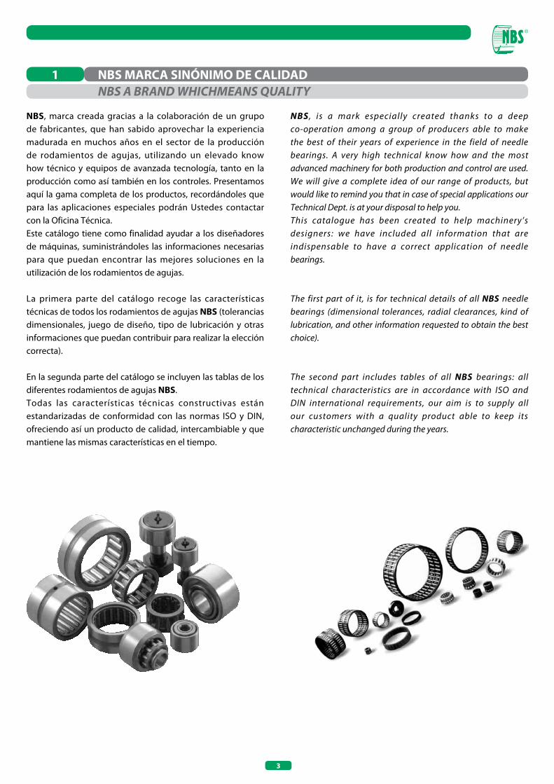
NBS, marca creada gracias a la colaboración de un grupo de fabricantes, que han sabido aprovechar la experiencia madurada en muchos años en el sector de la producción de rodamientos de agujas, utilizando un elevado know how técnico y equipos de avanzada tecnología, tanto en la producción como así también en los controles. Presentamos aquí la gama completa de los productos, recordándoles que para las aplicaciones especiales podrán Ustedes contactar con la Oficina Técnica. Este catálogo tiene como finalidad ayudar a los diseñadores de máquinas, suministrándoles las informaciones necesarias para que puedan encontrar las mejores soluciones en la utilización de los rodamientos de agujas.
La primera parte del catálogo recoge las características técnicas de todos los rodamientos de agujas NBS (tolerancias dimensionales, juego de diseño, tipo de lubricación y otras informaciones que puedan contribuir para realizar la elección correcta).
En la segunda parte del catálogo se incluyen las tablas de los diferentes rodamientos de agujas NBS.Todas las características técnicas constructivas están estandarizadas de conformidad con las normas ISO y DIN, ofreciendo así un producto de calidad, intercambiable y que mantiene las mismas características en el tiempo.
NBS A BRAND WHICHMEANS QUALITY
NBS , is a mark especially created thanks to a deep co-operation among a group of producers able to make the best of their years of experience in the field of needle bearings. A very high technical know how and the most advanced machinery for both production and control are used. We will give a complete idea of our range of products, but would like to remind you that in case of special applications our Technical Dept. is at your disposal to help you.This catalogue has been created to help machinery’s designers: we have included all information that are indispensable to have a correct application of needle bearings.
The first part of it, is for technical details of all NBS needle bearings (dimensional tolerances, radial clearances, kind of lubrication, and other information requested to obtain the best choice).
The second part includes tables of all NBS bearings: all technical characteristics are in accordance with ISO and DIN international requirements, our aim is to supply all our customers with a quality product able to keep its characteristic unchanged during the years.
4
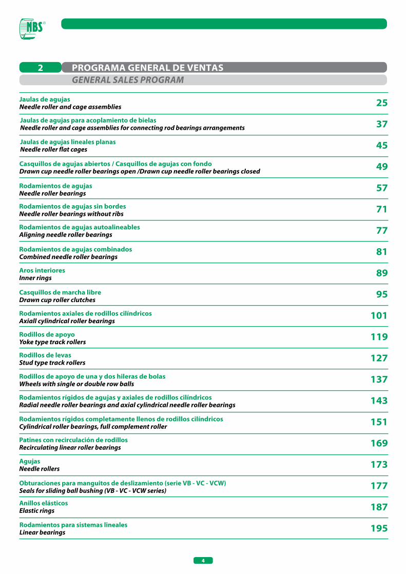
Jaulas de agujas Needle roller and cage assemblies
Casquillos de agujas abiertos / Casquillos de agujas con fondo Drawn cup needle roller bearings open /Drawn cup needle roller bearings closed
25
37
45
49
57
71
77
81
89
95
101
119
127
137
143
151
169
173
177
187
195
Rodamientos de agujas Needle roller bearings
Rodamientos de agujas sin bordesNeedle roller bearings without ribs
Rodamientos de agujas autoalineablesAligning needle roller bearings
Rodamientos de agujas combinadosCombined needle roller bearings
Aros interioresInner rings
Casquillos de marcha libreDrawn cup roller clutches
Rodamientos axiales de rodillos cilíndricosAxiall cylindrical roller bearings
Rodillos de apoyoYoke type track rollers
Rodillos de levasStud type track rollers
Rodillos de apoyo de una y dos hileras de bolas Wheels with single or double row balls
Rodamientos rígidos de agujas y axiales de rodillos cilíndricosRadial needle roller bearings and axial cylindrical needle roller bearings
Rodamientos rígidos completamente llenos de rodillos cilíndricosCylindrical roller bearings, full complement roller
Jaulas de agujas para acoplamiento de bielasNeedle roller and cage assemblies for connecting rod bearings arrangements
Jaulas de agujas lineales planasNeedle roller flat cages
Patines con recirculación de rodillosRecirculating linear roller bearings
AgujasNeedle rollers
Anillos elásticosElastic rings
Obturaciones para manguitos de deslizamiento (serie VB - VC - VCW)Seals for sliding ball bushing (VB - VC - VCW series)
Rodamientos para sistemas linealesLinear bearings
PROGRAMA GENERAL DE VENTAS2GENERAL SALES PRoGRAM
5
GENERALIDADES 3
COEFICIENTES DE CARGA 4
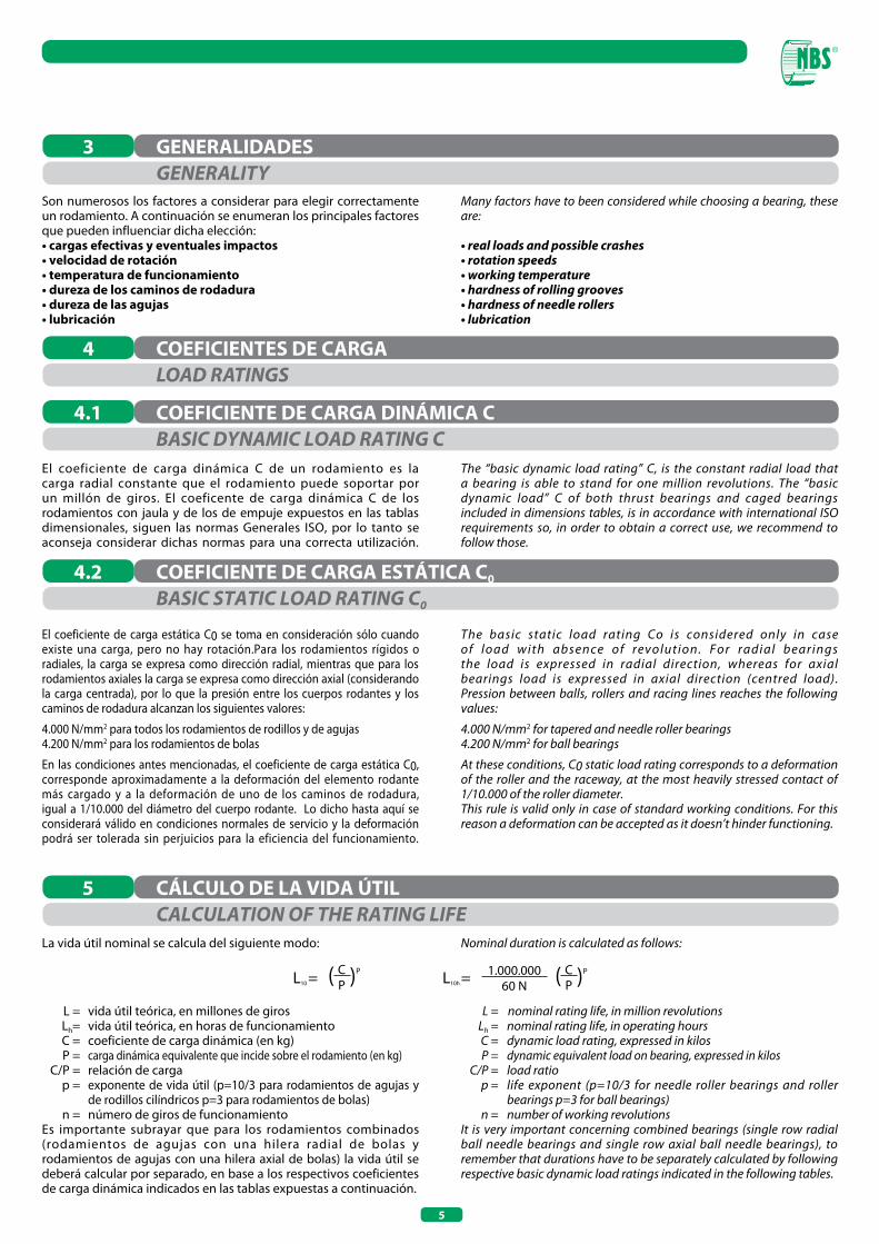
Son numerosos los factores a considerar para elegir correctamente un rodamiento. A continuación se enumeran los principales factores que pueden influenciar dicha elección:• cargas efectivas y eventuales impactos• velocidad de rotación• temperatura de funcionamiento• dureza de los caminos de rodadura• dureza de las agujas• lubricación
COEFICIENTE DE CARGA DINÁMICA C4.1
El coeficiente de carga dinámica C de un rodamiento es la carga radial constante que el rodamiento puede soportar por un millón de giros. El coeficente de carga dinámica C de los rodamientos con jaula y de los de empuje expuestos en las tablas dimensionales, siguen las normas Generales ISO, por lo tanto se aconseja considerar dichas normas para una correcta utilización.
COEFICIENTE DE CARGA ESTÁTICA C04.2
El coeficiente de carga estática C0 se toma en consideración sólo cuando existe una carga, pero no hay rotación.Para los rodamientos rígidos o radiales, la carga se expresa como dirección radial, mientras que para los rodamientos axiales la carga se expresa como dirección axial (considerando la carga centrada), por lo que la presión entre los cuerpos rodantes y los caminos de rodadura alcanzan los siguientes valores:
4.000 N/mm2 para todos los rodamientos de rodillos y de agujas4.200 N/mm2 para los rodamientos de bolas
En las condiciones antes mencionadas, el coeficiente de carga estática C0, corresponde aproximadamente a la deformación del elemento rodante más cargado y a la deformación de uno de los caminos de rodadura, igual a 1/10.000 del diámetro del cuerpo rodante. Lo dicho hasta aquí se considerará válido en condiciones normales de servicio y la deformación podrá ser tolerada sin perjuicios para la eficiencia del funcionamiento.
La vida útil nominal se calcula del siguiente modo:
L = vida útil teórica, en millones de giros Lh= vida útil teórica, en horas de funcionamiento C = coeficiente de carga dinámica (en kg) P = carga dinámica equivalente que incide sobre el rodamiento (en kg) C/P = relación de carga p = exponente de vida útil (p=10/3 para rodamientos de agujas y
de rodillos cilíndricos p=3 para rodamientos de bolas) n = número de giros de funcionamientoEs importante subrayar que para los rodamientos combinados (rodamientos de agujas con una hilera radial de bolas y rodamientos de agujas con una hilera axial de bolas) la vida útil se deberá calcular por separado, en base a los respectivos coeficientes de carga dinámica indicados en las tablas expuestas a continuación.
CÁLCULO DE LA VIDA ÚTIL5
GENERALITY
LoAD RATINGS
BASIC DYNAMIC LoAD RATING C
BASIC STATIC LoAD RATING C0
CALCULATIoN oF THE RATING LIFE
Many factors have to been considered while choosing a bearing, these are:
• real loads and possible crashes• rotation speeds• working temperature• hardness of rolling grooves• hardness of needle rollers• lubrication
The “basic dynamic load rating” C, is the constant radial load that a bearing is able to stand for one million revolutions. The “basic dynamic load” C of both thrust bearings and caged bearings included in dimensions tables, is in accordance with international ISO requirements so, in order to obtain a correct use, we recommend to follow those.
The basic static load rating Co is considered only in case of load with absence of revolution. For radial bearings the load is expressed in radial direction, whereas for axial bearings load is expressed in axial direction (centred load).Pression between balls, rollers and racing lines reaches the following values:
4.000 N/mm2 for tapered and needle roller bearings4.200 N/mm2 for ball bearings
At these conditions, C0 static load rating corresponds to a deformation of the roller and the raceway, at the most heavily stressed contact of 1/10.000 of the roller diameter.This rule is valid only in case of standard working conditions. For this reason a deformation can be accepted as it doesn’t hinder functioning.
Nominal duration is calculated as follows:
L = nominal rating life, in million revolutions Lh = nominal rating life, in operating hours C = dynamic load rating, expressed in kilos P = dynamic equivalent load on bearing, expressed in kilos C/P = load ratio p = life exponent (p=10/3 for needle roller bearings and roller
bearings p=3 for ball bearings) n = number of working revolutionsIt is very important concerning combined bearings (single row radial ball needle bearings and single row axial ball needle bearings), to remember that durations have to be separately calculated by following respective basic dynamic load ratings indicated in the following tables.
L10 = ( )CP
P L10h = ( )CP
P1.000.00060 N
6
En los casos que resulte necesario definir que tipo de rodamiento adoptar en las diversas aplicaciones, será importante evaluar cual es la vida útil prevista para el equipo y si el mismo se utilizará en modo continuo o discontinuo. Si no se cuenta con una experiencia previa al respecto es posible tomar como referencia la siguiente tabla:
Horas de funcionamiento Tipo de equipo • de 4.000 a 8.000 - aparatos para trabajos domésticos, máquinas
a g r í c o l a s ( m á q u i n a s c o n f u n c i o n a m i e n t o i n t e r m i t e n t e p a r a l a s c u a l e s e v e n t u a l e s i n t e r r u p c i o n e s t i e n e n p o c a i m p o r t a n c i a ) .
• de 8.000 a 12.000 - máquinas herramienta empleadas en modo discontinuo, motores para electrodomésticos, aparatos de manipulac ión (máquinas con funcionamiento breve para las cuales eventuales interrupciones pueden tener importancia) .
• de 12.000 a 24.000 - máquinas utilizadas las 24 horas, pero no en modo continuo (motores eléctricos, engranajes).
• de 24.000 a 30.000 - m á q u i n a s u t i l i z a d a s l a s 2 4 h o r a s , e n m o d o c o n t i n u o , m á q u i n a s h e r r a m i e n t a s y o t r a s m á q u i n a s p a r a l a i n d u s t r i a .
• de 30.000 a 1000.000 - m á q u i n a s f u n c i o n a n t e s l a s 2 4 h o r a s d e l d í a y q u e a d e m á s r e q u i e r e n l a m á x i m a fiabilidad, bombas, compresores, impresoras, generadores de energía, provisión de agua.
Se denomina vida útil de servicio el límite máximo de durabilidad que el rodamiento alcanza en la aplicación. Es obvio que calcular la vida útil de servicio puede resultar bastante complicado, ya que las variables que pueden influir sobre la misma son múltiples, como por ejemplo los desfasajes entre el eje y el alojamiento, la lubricación, la temperatura de servicio. Es aconsejable siempre tener en cuenta eventuales experiencias de utilización previas.
La carga estática equivalente Po, está limitada por el coeficiente de seguridad estático So, y se deberá considerar como carga radial para rodamientos rígidos con carga axial y centrada para rodamientos axiales, por lo tanto:
• Rodamientos de agujas de tipo radialPo = Fr
donde Po = carga estática equivalente (en kg.) Fr = carga radial efectiva (en kg.)
• Rodamientos de agujas de tipo axialPo = Fa
donde Fa = carga axial efectiva (en kg.)
VIDA ÚTIL TEÓRICA REQUERIDA
VIDA ÚTIL DE SERVICIO
CARGA ESTÁTICA EQUIVALENTE P0
5.1
5.2
5.3
RATING LIFE REQUESTED
oPERATING LIFE
EQUIVALENT STATIC LoAD P0
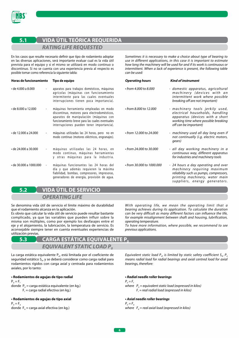
Sometimes it is necessary to make a choice about type of bearing to use in different applications, in this case it is important to estimate how long the machinery will be used for and if its work is continuous or intermittent. When a lack of experience is present, the following table can be used:
operating hours Kind of instrument • from 4.000 to 8.000 - domestic apparatus, agricoltural
m a c h i n e r y ( d e v i c e s w i t h a n intermittent work where possible
breaking off are not important)
• from 8.000 to 12.000 - m a c h i n e r y t o o l s j e r k i l y u s e d , electrical households, handling
apparatus (devices with a short working time where possible breaking off can be important)
• from 12.000 to 24.000 - machinery used all day long even if not continually (i.g. electric motors, gears)
• from 24.000 to 30.000 - all day working machinery in a continuous way, different apparatus for industries and machinery tools
• from 30.000 to 1000.000 - 24 hours a day operating and over m a c h i n e r y r e q u i r i n g m a x i m u m reliability such us pumps, compressors, printing machinery, water main s u p p l i e r s , e n e r g y g e n e r a t o r s .
With operating l ife, we mean the operating l imit that a bearing achieves during its application. To calculate the duration can be very difficult as many different factors can influence the life, for example misalignment between shaft and housing, lubrification, operating temperature.To have more information, where possible, we recommend to see previous applications.
Equivalent static load Po, is limited by static safety coefficient So, Po means radial load for radial bearings and axial centred load for axial bearings, therefore:
• Radial needle roller bearings Po = Fr
where Po = equivalent static load (expressed in kilos) Fr = real radial load (expressed in kilos)
• Axial needle roller bearings Po = Fa where Fa = real axial load (expressed in kilos)

7
Valores indicativos del coeficiente de seguridad estático S0S0 static safety load rating coefficient
Condiciones operativas - Working conditions
Elevada precisión de rotación, con cargas e impactosHigh rotation precision, with heavy loads and impacts
Precisión normal de rotación, con mayores exigencias de silenciosidadNormal rotation precision, with greater need of noiselessness
Precisión de rotación limitada, bajas cargas, mínimas exigencias de silenciosidadLow rotation precision, low loads and minimal need of noiselessness
La carga dinámica equivalente P en un rodamiento rígido se determina generalmente a partir de las características de la máquina y/o del equipo en el cual se utilizará. Resulta muchas veces determinante tener en cuenta las cargas accidentales que pueden surgir a causa de la utilización de la máquina misma, como por ejemplo vibraciones, impactos y sobrecargas en los componentes. Por lo tanto calcular la carga efectiva puede resultar complicado, ya que sería necesario considerar muchos factores. La mejor guía la constituye siempre la experiencia adquirida en montajes previamente realizados. Además es necesario hacer una distinción entre rodamientos de tipo axial y de tipo radial o rígidos, en los cuales, para calcular la carga dinámica equivalente podemos utilizar las siguientes fórmulas:
• Rodamientos de agujas de tipo radial(considerando Fr constante)P = Fr donde P = carga dinámica equivalente (en kg.) Fr = carga radial efectiva (en kg.)
• Rodamientos de agujas de tipo axial(considerando la carga centrada)P = Fa
donde Fa = carga axial efectiva (en kg.)
CARGA DINÁMICA EQUIVALENTE P5.4
La capacidad de carga estática no es otra cosa que la capacidad de un rodamiento de soportar cargas aplicadas en ausencia de movimiento o bien en presencia de oscilaciones muy lentas. Dichas cargas pueden de todos modos crear deformaciones, a veces permanentes, si bien en algunos casos las mismas pueden ser consideradas aceptables. De aquí surge el concepto de coeficiente de seguridad estático, que indica el grado de seguridad del rodamiento contra eventuales deformaciones. El coeficiente de seguridad estático, puede calcularse con la siguiente fórmula:
considerando que: So - factor de seguridad estático Co - coeficiente de carga estática (en kg) Po - carga admisible (en kg)
COEFICIENTE DE SEGURIDAD ESTÁTICO SO5.5
Rodamientode rodillos y agujas
Tapered andneedle bearings
3
1,5
1
Rodamientos de bolas
Rollerbearings
2
1
0,5
EQUIVALENT DYNAMIC LoAD P
STATIC LoAD SAFETY FACToR So
Co
PoSo =
The equivalent dynamic load P on a radial or thrust bearing, is usually determined by starting from characteristics of the machinery and/or of the special equipment on which it is assembled. It is often important to keep present accidental loads that a machinery is able to produce during its work, such as vibrations, impacts, overloads. It’s clear that the calculation of real load can be very hard and at the light of this we recommend once again, where possible, to see previous applications. A further distinction between axial and radial bearings, has to be made: the fol lowing formula can be used to determinate equivalent dynamic load:
• Radial needle roller bearings(where Fr is constant)P = Fr
where P = equivalent dynamic load (expressed in kilos) Fr = real radial load (expressed in kilos)
• Axial needle roller bearings(load is centred)P = Fawhere Fa = real axial load (expressed in kilos)
The static load ability of a bearing is its ability to stand l o a d s w h e n t h e r e i s n o m o v e m e n t a t a l l o r w h e n t h e oscillations are very slow. Even in these cases loads can produce deformations, sometimes permanent, even if rather acceptable in some applications. Here comes the static coefficient of safety, able to indicate the safety degrees of a bearing against deformations. Static load safety factor,can be calculated by using the following formula:
where: So - static factor of safety Co - static load rating, in kilos Po - possible load, in kilos

8
Es importante de todos modos tener en cuenta siempre la temperatura de servicio a la cual trabajará el rodamiento de agujas, ya que si cambia la temperatura pueden variar las condiciones del rodamiento: por ejemplo cuando se trabaja a temperaturas de servicio muy elevadas, la dureza del material del rodamiento varía, por lo tanto, como podemos imaginar, la carga que soportará el rodamiento será sin duda inferior. Operando con temperaturas superiores a los 120° los coeficientes de carga dinámica y estática cambiarán, disminuyendo las capacidades de carga efectivas. (Para los rodamientos con obturaciones RS y 2RS se aconseja no superar los + 80 °C).
Para aplicaciones con una temperatura de servicio de aproximadamente 120º o superior, sería oportuno someter el rodamiento (más precisamente los aros) a un tratamiento térmico de estabilización, evitando así que puedan surgir variaciones dimensionales significativas que puedan comprometer la correcta utilización de los rodamientos de agujas.
Otro componente fundamental para una correcta utilización de los rodamientos de agujas es sin duda la lubricación, ya que, sobre todo a elevadas temperaturas, la utilización de una grasa o un aceite no adecuados puede sin duda influenciar el buen funcionamiento del rodamiento, causando recalentamiento y desgaste excesivo. En los capítulos que siguen se darán explicaciones más detalladas sobre la lubricación con aceite y con grasa.
INFLUENCIA DE LA TEMPERATURA DE SERVICIO6
Para los rodamientos de agujas, las jaulas de agujas, etc, que se montan sin aro interior o exterior y que utilizan por lo tanto el eje como sede de deslizamiento, será oportuno que los caminos de rodadura y las agujas tengan ambos una dureza comprendida entre 58 y 64 HRC. Si los caminos de rodadura tienen una dureza inferior a la aconsejada obviamente la capacidad de carga disminuirá y aumentará el desgaste. Resulta útil al respecto utilizar la tabla expuesta a continuación, multiplicando el coeficiente de carga dinámica por el correspondiente valor de dureza del camino de rodadura:
Dureza (expresada en HRC)
60 58 55 50 48 45 40 35 30 25
Factores de reducción de las cargas
1 1 0,7 0,55 0,48 0,41 0,32 0,24 0,17 0,11
Para la fabricación de los caminos de rodadura se pueden emplear aleaciones de acero, con un adecuado grado de pureza, como por ejemplo:
• Aceros típicos al cromo• Aceros de cementación• Aceros templados con llama o por inducción
ESTRUCTURA DE LOS CAMINOS DE RODADURA 7
INFLUENCE oF oPERATING TEMPERATURElt’s always important to consider operating temperature of a bearing during its work: if temperature changes bearing conditions do the same.For instance, the hardness of bearing material changes whenthere is an application requiring very high temperatures: in this casethe bearing is able to stand lower load.In case of applications where temperatures are higher than 120° both static and dynamic load rating change: the real load ability will be lower (for RS and 2RS bearings, we suggest not to exceed 80 °C)
During applications where temperature is 120° and more, it is better to submit the bearing or better, its rings, to some thermal treatments to stabilisation, avoiding in this way possible strong dimensional changes that could compromise the right use of needle roller bearings.
Lubrication is another basic factor for a correct use of bearings:where temperatures are high the utilisation of a wrong greaseor oi l can inf luence good work of bearing, b y ca us i ngoverheating or excessive wear.Details concerning lubrication in the following chapters.
MATERIALS FoR RoLLING BEARING RACEWAYSFor needIe roller bearings and needIe roller cages assembled without inner or outer ring and able therefore to use the shaft as sliding place, both rolling bearing raceways and roller must have an hardness included between 58 and 64 HRC.If rolling grooves do not reach this target, their loading ability decreases and wear increases.The following table can be used by multiplicand basic dynamic load rating for correspondent factor of hardness of rolling bearing raceways:
Hardness (expressed in HRC)
60 58 55 50 48 45 40 35 30 2
Loads reduction factors
1 1 0,7 0,55 0,48 0,41 0,32 0,24 0,17 0,11
D u r i n g t h e c h o i c e o f m a t e r i a l s t h a t w i l l b e u s e d f o r manufacturing rolling bearing raceways, different kind of steeI can be used, obviously they have a different kind of purity, these are:
• all tempering steeIs• tempering surface steeIs• fire tempering steeIs or induction tempering steeIs
9
La velocidad máxima admisible de rotación de un rodamiento depende de numerosos factores, que se deberán considerar en su totalidad, para contar así con un dato lo suficientemente atendible. A continuación enumeramos las variables más importantes que se deberán tener en cuenta para conocer el número máximo de giros que puede soportar un rodamiento.
• tipo de rodamiento (forma y dimensiones). • carga• lubricación (aceite o grasa).• factor de enfriamiento
En otros casos pueden resultar determinantes ciertos factores como por ejemplo la silenciosidad y la función de estanqueidad, siempre y cuando hayan sido respetados los siguientes criterios:
• montaje correcto• juego de servicio normal• condiciones constantes de funcionamiento
Es necesario puntualizar que en aplicaciones especiales, en las cuales es necesario superar el número de giros admisible, es oportuno tomar ciertas medidas, como por ejemplo realizar una lubricación de circulación de aceite. Para velocidades de rotación muy elevadas es conveniente utilizar una lubricación como la que hemos citado, integrándola con un dispositivo de enfriamiento del aceite o, en casos extremos, utilizando una lubricación .de niebla o inyección de aceite. En ciertas aplicaciones especiales es aconsejable también la utilización de jaulas especiales.
NÚMERO DE GIROS y VELOCIDAD MÁxIMA ADMISIBLE8
La lubricación es sin duda uno de los factores más importantes para el buen funcionamiento de un rodamiento, ya que evita la fricción entre los cuerpos rodantes, los aros y la jaula y constituye además una protección importante contra algunos agentes externos como el polvo o la humedad, evitando la corrosión y el desgaste.La cantidad de producto lubricante necesaria para los rodamientos es muy pequeña (excepto cuando tiene funciones particulares de sellado o de disipación de calor). La lubricación se logra utilizando grasa o bien aceite. (Véase más adelante el capítulo específico relativo a la lubricación con aceite y con grasa). Es necesario subrayar que tanto el aceite como la grasa utilizados deberán estar libres de impurezas, ya que basta un grano de arena o una pequeña partícula de metal para dañar el rodamiento. El lubricante con el tiempo pierde su eficacia, por ello se aconseja efectuar siempre el relleno períodico necesario para un buen funcionamiento del rodamiento, teniendo siempre en cuenta todas las variables de funcionamiento y las particulares condiciones de servicio (polvo, humedad, temperatura excesiva). Naturalmente para los rodamientos con lubricación de por vida no será necesario preocuparse de la lubricación, ya que los mismos han sido estudiado para particulares aplicaciones donde no resulta posible la relubricación periódica.
LUBRICACIÓN9
NUMBER oF REVoLUTIoNS AND MAXIMUM SPEED ALLoWEDLimiting speed of a bearing depends on many factors: all of them have to be considered in order to have reliable specifications.Here the most important factors able to influence limiting speeds:
• type of bearing (shape and dimension)• load• lubrication (oil or grease) • cooling factor
In other cases it is also important low noise property and seal ability if the following rules are respected:
• right assembling• normal clearance• constant work conditions
An oil lubrication is required when special applications are present and higher number of revolutions than those allowed, have to be reached.In case of very high rotation speeds, besides using an oil lubrication , a cooling oil device must be used as long as a “fog lubrication” or an “oil injection”.Particular cages must be used in case of special applications.
LUBRICATIoNL u b r i c a t i o n i s o n e o f t h e m o s t i m p o r t a n t o p e r a t i o n s effecting bearing life, as it prevents friction among rolling elements, rings and cage, and it protects against external factors such us dust and humidity avoiding therefore wear and tear.The quantity of lubricant for a bearing is really small, unless it has to bear particular sealing duties or heat dissipation.Either grease or oil may be used: each has its advantages and limitations (see specific chapter for lubrication).Both grease and oil have to be devoid of any impurity: even a grind of sand or a small metal particle could damage the bearing.Lubricant looses its efficacy while passing the time, this is thereason why we recommend to top it up periodically: a goodupkeep help the bearing to have a good functioning.Life self lubricated bearings do not require any upkeep, as they are purposely studied for special applications where relubrication is not possible.
10
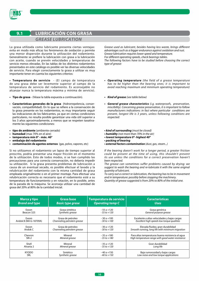
Marca y tipoBrand and type
Grasa baseBasic type grase
Temperatura de serviciooperating temp C
CaracterísticasUses
Grasa genéricaGeneral purpose grease
Excelente a altas velocidades y bajas cargasExcellent high speeds low torque qualities
Elevada fluidez, gran durabilidadSmooth running, long life with minimum migration
Para altas temperaturas buena resistencia al aguaHigh temperature range with good water resistance
Gran durabilidadLong life
Baja rumorosidad y bajas cargasLow noise and low torque applications
- 55 a +120- 55 to +120
- 30 a +100- 30 to +100
- 30 a +120- 30 to +120
- 35 a +180- 35 to +180
- 35 a +120- 35 to +120
- 40 a +150- 40 to +150
Grasa sintéticaSynthetic grease
Grasa de petroleoChanneling petrolem grease
Grasa de petroleoChanneling petrolem grease
MineralMineral grease
MineralMineral grease
SintéticoSynthetic grease
ExxonBeacon 325
ExxonAndok B (Mil-G-18709A)
ExxonAndok C
ChevronSRI-2
ShellAlvania 2
KYODOSRL
La grasa utilizada como lubricante presenta ciertas ventajas: evita en modo más eficaz los fenómenos de oxidación y permite una menor dispersión durante la utilización del rodamiento. Generalmente se prefiere la lubricación con grasa a la lubricación con aceite, cuando se prevén velocidades y temperaturas de servicio menos elevadas. En las tablas de los distintos rodamientos presentados en este catálogo es posible ver las diversas velocidades de servicio. Para elegir correctamente la grasa a utilizar es muy importante tener en cuenta los siguientes criterios:
• Temperatura de servicio - (El campo de temperatura de una grasa debe ser levemente superior al campo de la temperatura de servicio del rodamiento. Es aconsejable no alcanzar nunca la temperatura máxima y mínima de servicio).
• Tipo de grasa - (Véase la tabla expuesta a continuación).
• Características generales de la grasa (hidrorrepelencia, conser- vación, compatibilidad). En lo que se refiere a la conservación de la grasa presente en los rodamientos, es muy importante seguir las indicaciones de los fabricantes, ya que en ciertas condiciones particulares, no resulta posible garantizar una vida útil superior a los 3 años aproximadamente, a menos que se respeten taxativa- mente las siguientes condiciones:
• tipo de ambiente (ambiente cerrado)• humedad (max 70% en el aire)• temperatura mín 0° - máx. 40°• embalaje del rodamiento• contaminación de agentes externos (gas, polvo, vapores, etc)
Si no utilizamos el rodamiento un lapso de tiempo superior al prescrito, podría presentar una mayor fricción en el momento de la utilización. Esto de todos modos, si se han cumplido las precauciones para una correcta conservación, no debería impedir su utilización. Si la grasa presenta problemas de lubricación a causa de un eventual secado, es posible efectuar el lavado y la relubricación del rodamiento con la misma cantidad de grasa empleada originalmente o en el primer montaje. Para efectuar una relubricación correcta es necesario que el rodamiento esté a su temperatura de funcionamiento y en rotación, en lo posible, antes de la parada de la máquina. Se aconseja utilizar una cantidad de grasa del 20% al 80% de la cantidad inicial.
LUBRICACIÓN CON GRASA9.1GREASE LUBRICATIoN
Grease used as lubricant, besides having less waste, brings different advantages such as a bigger endurance against oxidation and rust.Grease lubrication requires lower speed and temperature.For different operating speeds, check bearings tables.The following factors have to be studied before choosing the correct type of grease:
• Operating temperature (the field of a grease temperature has to be higher than the bearing ones; it is important to avoid reaching maximum and minimum operating temperature)
• Kind of grease (see table below)
• General grease characteristics (i.g. waterproofs, preservation, miscibility). Concerning grease preservation, it is important to follow manufacturers indications: in fact where particular conditions are present, longest life is 3 years, unless following conditions are respected:
• kind of surrounding (must be closed)• humidity (not more than 70% in the air) • lowest temperature 0°- highest 40°• packing of bearing• external factors contamination (dust, gas, steam...)
lf the bearing doesn’t work for a longer period, a greater frictioncould be present at the time of using, this shouldn’t preventits use unless the conditions for a correct preservation haven’tbeen respected.The grease can sometimes suffer problems caused by drying: we suggest to wash the bearing and re-lubricate it with the same original quantity of lubricant.To carry out a correct re-lubrication, the bearing has to be in movement and in temperature: possibly before stopping the machinery.Quantity of grease suggested is from 20% to 80% of the initial one.

11
La lubricación con aceite se emplea generalmente cuando se trata de aplicaciones que necesitan alcanzar altas velocidades y cargas elevadas que requieren dispersión del calor de los rodamientos o bien cuando las partes adyacentes están ya lubricadas con aceite. En general se aconseja la utilización de aceites minerales refinados sin aditivos. Para aplicaciones particulares se pueden utilizar aceites con aditivos y también aceites de tipo sintético, aconsejados sobre todo para trabajar con altas temperaturas. En líneas generales sería oportuno elegir un aceite lubricante que presente una viscosidad tal que garantice, a la temperatura de funcionamiento del rodamiento, un valor que no descienda por debajo de los 12mm2/s.Si se efectúan aplicaciones especiales, donde se alcanzan números de giros muy elevados, es aconsejable utilizar aceites fluidos que puedan garantizar la máxima fluidez y por lo tanto la menor fricción de los cuerpos rodantes.
La elección del tipo de lubricación depende sobre todo de la aplicación que se deberá efectuar y de las velocidades que deberá alcanzar el rodamiento. Enumeramos a continuación los tipos de lubricación más utilizados:
9.3.1 Lubricación por goteo de aceite: se utiliza para los rodamientos rígidos; garantiza un elevado número de giros, pero puede ser utilizada sólo cuando el rodamiento cuenta con orificio de lubricación en el aro exterior.
9.3.2 Lubricación en baño de aceite: recibe también otros nombres (por inmersión o copa de aceite), se emplea generalmente para bajas velocidades, aproximadamente la mitad de los giros que el rodamiento puede realmente alcanzar.
Es idónea para los montajes en eje horizontal, el nivel del baño con el rodamiento detenido debe alcanzar el punto más bajo del camino de rodadura. La cantidad de aceite no debe resultar demasiado escasa, ya que esto llevaría a cambiar el aceite con mucha frecuencia; además se aconseja un control constante del nivel del aceite a través del respectivo indicador.
9.3.3 Lubricación por circulación de aceite: se emplea cuando se alcanzan velocidades y temperaturas elevadas; este sistema debería garantizar un menor desgaste del rodamiento y un menor recambio de aceite. Mediante una filtración es posible mantener la temperatura de funcionamiento baja.
9.3.4 Lubricación con niebla de aceite: se utiliza cuando se deben alcanzar elevadas velocidades de rotación, ya que este sistema de lubricación funciona inyectando pequeñas cantidades de aceite dosificables, pulverizadas en una corriente de aire. El aire debe ser seco y sin ningún tipo de impurezas. La sobrepresión que se crea dentro de la máquina debería garantizar la exclusión de cualquier agente contaminante exterior, como polvo, residuos, vapores, humedad, etc.
9.3.5 Lubricación con aceite centralizada: se utiliza cuando existe la necesidad de lubricar equipos en diferentes puntos; generalmente esto se logra con una bomba centralizada que se encarga de la distribución del aceite en las diferentes zonas. Tiene la indudable ventaja de presentar un mayor control de la dosificación del líquido de lubricación y de la filtración.
LUBRICACIÓN CON ACEITE
TIPOS DE LUBRICACIÓN CON ACEITE
9.2
9.3
oIL LUBRICATIoN
KINDS oF oIL LUBRICATIoN
Oil lubrication is usually required in presence of special applications requiring high speeds and of loads requiring leak of heat, or when adjacent parts are already oil lubricated.As a general rule we recommend to use mineral oils, purified without additives.For special applications both oils with additive and synthetic oils can be used, these latter are particularly indicated to reach high temperatures.However the best choice will be a lubricant with a viscosity able to ensure operating temperature with a value not lower than 12mm2/s.In case of special applications where very high speeds are reached, light oils must be used: these are able to guarantee top fluidity and lowest friction, besides a lower development of heat.
Applications and speeds influence the type of lubrication to choose, here the most important types of it:
9.3.1 Drip feed oil lubrication: for axial bearings, it guarantees high number of revolutions; bearings have to be supplied with lubrication hole on the outer ring.
9.3.2 oil bath lubrication: generally known as immersion or bowl oil. lt’s mostly used for low speeds, i.g. half revolutions of bearing ability.
Suitable for horizontal axle mounting the level of oil must reach the lowest point of inner rolling grooves, bearing has to stand still.
Oil quantity doesn’t have to be too poor to avoid reducing gaps during oil changes, besides a constant check of oil level by appropriate indicator is required.
9.3.3 Recirculating oil lubrication: requested when very high speeds and revolutions must be reached: this method guarantees lower wear an infrequent substitution of oil.
Thanks to a filtration it is possible to keep low temperatures.
9.3.4 Fog oil lubrication: required when high revolutions speeds must be reached.
This system works thanks to the injection of very small quantity of oil, which will be pulverised in a draught.
The air must be pure and free from any impurity. The overpressure created in this way, should guarantee the
exclusion of any external contaminating factors such as dust, humidity, steam, rubble
9.3.5 Centralised oil lubrication: necessary when there is a need of lubricating the equipment in different points, usually it’s a centralised pump that distributes oil among different interested parts.
It offers a control about the level of liquid used for lubrication by a filtration.
12
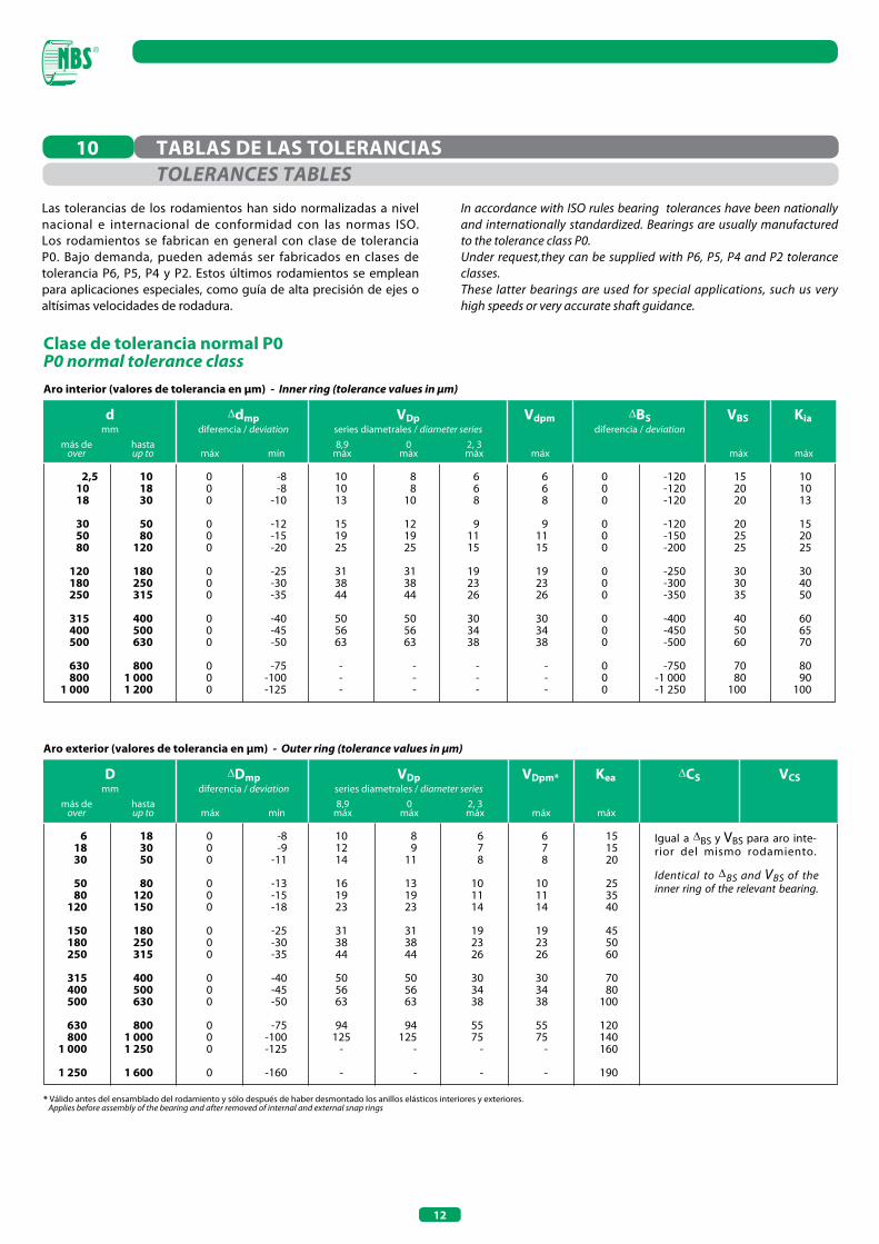
Clase de tolerancia normal P0P0 normal tolerance classAro interior (valores de tolerancia en µm) - Inner ring (tolerance values in µm)
Aro exterior (valores de tolerancia en µm) - Outer ring (tolerance values in µm)
* Válido antes del ensamblado del rodamiento y sólo después de haber desmontado los anillos elásticos interiores y exteriores. Applies before assembly of the bearing and after removed of internal and external snap rings
Las tolerancias de los rodamientos han sido normalizadas a nivel nacional e internacional de conformidad con las normas ISO. Los rodamientos se fabrican en general con clase de tolerancia P0. Bajo demanda, pueden además ser fabricados en clases de tolerancia P6, P5, P4 y P2. Estos últimos rodamientos se emplean para aplicaciones especiales, como guía de alta precisión de ejes o altísimas velocidades de rodadura.
TABLAS DE LAS TOLERANCIAS10
dmm
Δdmpdiferencia / deviation
ΔBSdiferencia / deviation
VDpseries diametrales / diameter series
Vdpm VBS Kia
más deover máx máx máx máx
8,9máx
hastaup to mín
0máx
2, 3máx
10 18 30 50 80
120 180 250
315 400 500
630 800 1 000
101830
5080
120
180250315
400500630
8001 0001 200
000
000
000
000
000
000
000
000
000
000
101013
151925
313844
505663
---
88
10
121925
313844
505663
---
668
91115
192326
303438
---
668
91115
192326
303438
---
152020
202525
303035
405060
7080
100
101013
152025
304050
606570
8090
100
-8-8
-10
-12-15-20
-25-30-35
-40-45-50
-75-100-125
-120-120-120
-120-150-200
-250-300-350
-400-450-500
-750-1 000-1 250
Dmm
ΔDmpdiferencia / deviation
ΔCSVDpseries diametrales / diameter series
VDpm* Kea VCS
más deover máx máx máx
8,9máx
hastaup to mín
0máx
2, 3máx
61830
5080
120
150180250
315400500
630800
1 000
1 250
183050
80120150
180250315
400500630
8001 0001 250
1 600
000
000
000
000
000
0
101214
161923
313844
505663
94125
-
-
89
11
131923
313844
505663
94125
-
-
678
101114
192326
303438
5575
-
-
678
101114
192326
303438
5575
-
-
151520
253540
455060
7080
100
120140160
190
Igual a ΔBS y VBS para aro inte-rior del mismo rodamiento.
Identical to ΔBS and VBS of the inner ring of the relevant bearing.
-8-9
-11
-13-15-18
-25-30-35
-40-45-50
-75-100-125
-160
2,5
ToLERANCES TABLESIn accordance with ISO rules bearing tolerances have been nationally and internationally standardized. Bearings are usually manufactured to the tolerance class P0.Under request,they can be supplied with P6, P5, P4 and P2 tolerance classes.These latter bearings are used for special applications, such us very high speeds or very accurate shaft guidance.

13
Dmm
ΔDmpdiferencia / deviation
ΔCSVDpseries diametrales / diameter series
KeaVDpm* SD VCS
más deover máx máxmáx máx
8,9máx
hastaup to mín
0, 2, 3máx
618305080
120150180250315400500630
18305080
120150180250315400500630800
0000000000000
88889
1010111313151820
5679
101113151820232835
455788
10111415172126
334556789
10121418
5678
101113151820232530
Igual a ΔBS y VBS para aro interior del mismo rodamiento.
Identical to ΔBS and VBS of the inner ring of the relevant bearing.
5556888
101113151820
-5-6-7-9
-10-11-13-15-18-20-23-28-35
dmm
Δdmpdiferencia / deviation
ΔBSdiferencia / deviation
Vdpseries diametrales / diameter series
Vdpm Kia VBS
más deover
superioruppermáx máx máx máx
8,9máx
hastaup to
inferiorlowermín
0, 2, 3máx
1018305080
120180250315400
0000000000
0000000000
55689
1013151823
445678
10121418
333455789
12
4445568
101315
5555678
101316
-5-5-6-8-9
-10-13-15-18-23
-40-80
-120-120-150-200-250-300-350-400
Clase de tolerancia P5P5 tolerance class
Aro exterior (valores de tolerancia en µm) - Outer ring (tolerance values in µm)
Aro interior (valores de tolerancia en µm) - Inner ring (tolerance values in µm)
* Válido antes del ensamblado del rodamiento y sólo después de haber desmontado los anillos elásticos interiores y exteriores. Applies before assembly of the bearing and after removed of internal and external snap rings
1018305080
120180250315
2,5
14
dmm
dmm
Dmm
dmm
dmm
Tdiferencia / deviation
Dmm
Δdmpdiferencia / deviation
ΔDmpdiferencia / deviation
ΔCS
ΔBSdiferencia / deviation
VDpseries diametrales / diameter series
VDpseries diametrales / diameter series
Vdpm
Vdpm
VDp
VDpm* Kea
VBS
SeSi Clase de tolerancia / Tolerance class
Kia
VCS
más deover
más deover
más deover
más deover
más deover máx
más deover
máx
máx
máx
máx
máx
máx
máx
máx máx
máx
máxmáx máx
P5P6P0
(tolerancias normales) P0
(normal tolerance)P0 (tolerancias normales)
P6, P5P0 (normal tolerance)
P6, P5
máx8,9
máx
8,9máx
hastaup to
hastaup to
hastaup to
hastaup to
hastaup to mín
hastaup to
mín
mín
mín
mín
0máx
0máx
2, 3máx
2, 3máx
1018305080
120180250315400500
-18305080
120180250315400500630800
1 000
1018305080
120180250315400500630800
1 0001 250
-18305080
120180250315400500630800
1 000
-305080
120180250315400500630800
1 000
305080
120180250315400500630800
1 0001 250
+20+20+20+25+25+30+40+40+50+60+70+80
+100
-250-250-300-300-400-400-400500
-500-600-750
-1 000-1 400
618305080
120150180250315400500630800
1018305080
120180250315400500630
18305080
120180250315400500630800
1 0001 250
18305080
120180250315400500630800
1 0001 2501 600
18305080
120180250315400500630800
1 0001 250
18305080
120150180250315400500630800
1 000
000000000000
00000000000000
000000000000000
00000000000000
678
101013182025303540
1010101015152025303035404550
556789
1013151821253035
99
10131519232831384450
910111416192325313541485675
778
101519232831384450
789
1116192325313541485675
55689
11141719232630
5678
10111415192125293445
55689
11141719232630
5678
10111415192125293445
89
101318202325303540506075
Igual a ΔBS y VBS para aro inte-rior del mismo rodamiento.
Idéntico a Si para la arandela para eje del mismo rodamiento.
Identical to ΔBS and VBS of the inner ring of the relevant bearing.
Identical to Si for the shaft washer of the relevant bearing.
-120-120-120-120-150-200-250-300-350-400-450-500
3334455779
11131518
152020202525303035404550
-7-7-8
-10-12-15-18-22-25-30-35-40
-8-10-12-15-20-25-30-35-40-45-50-75
-100-125
-11-13-16-19-22-25-30-35-40-45-50-75
-100-125-160
689
1115192326303438
---
8101214171923263034385575
--
-7-8-9
-11-13-15-18-20-25-28-33-38-45-60
000000000000
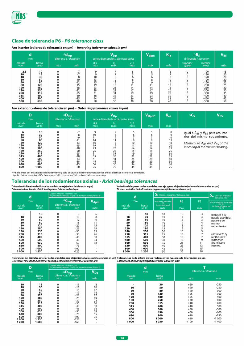
Clase de tolerancia P6 - P6 tolerance class
Tolerancias de los rodamientos axiales - Axial bearings tolerances
Aro interior (valores de tolerancia en µm) - Inner ring (tolerance values in µm)
Tolerancias del diámetro del orificio de las arandelas para eje (valores de tolerancias en µm)Tolerances for bore diameter of shaft locating washer (tolerance values in µm)
Variación del espesor de las arandelas para eje y para alojamiento (valores de tolerancias en µm)Tickness variation in shaft and housing washers (tolerance values in µm)
Aro exterior (valores de tolerancia en µm) - Outer ring (tolerance values in µm)
* Válido antes del ensamblado del rodamiento y sólo después de haber desmontado los anillos elásticos interiores y exteriores. Applies before assembly of the bearing and after removed of internal and external snap rings
superiorupper
inferiorlower
Δdmpdiferencia / deviation
ΔDmpdiferencia / deviation
Clase de tolerancia / Tolerance classP0 (tolerancias normales) P6 y P5 / P0 (normal tolerance), P6 and P5
Clase de tolerancia / Tolerance classP0 (tolerancias normales) P6 y P5 / P0 (normal tolerance), P6 and P5
Clase de tolerancia Tolerance class
Tolerancias del diámetro exterior de las arandelas para alojamiento (valores de tolerancias en µm)Tolerances for outside diameter of housing locatin washers (tolerance values in µm)
Tolerancias de la altura de los rodamientos (valores de tolerancias en µm)Tolerances of bearing height (tolerance values in µm)
2,5
15
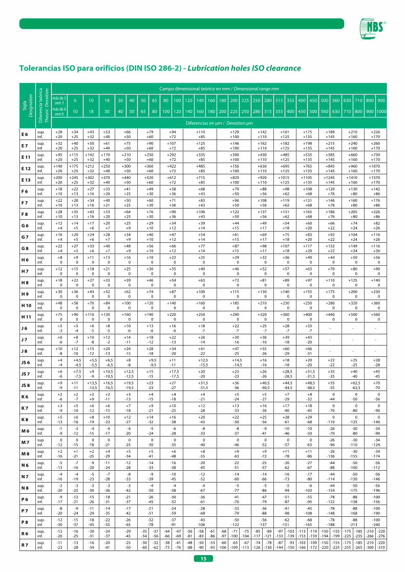
Tolerancias ISO para orificios (DIN ISO 286-2) - Lubrication holes ISo clearance
Sigl
aD
esig
natio
n
Dife
renc
ia te
óric
aTh
eoric
Dev
iatio
n Campo dimensional teórico en mm / Dimensional range mm
más de 3over 3 6 10 18 30 40 50 65 80 100 120 140 160 180 200 225 250 280 315 355 400 450 500 560 630 710 800 900
más de 6over 6 10 18 30 40 50 65 80 100 120 140 160 180 200 225 250 280 315 355 400 450 500 560 630 710 800 900 1000
Diferencias en μm / Deviation μm
E 6 sup.inf.
+28+20
+34+25
+43+32
+53+40
+66+50
+79+60
+94+72
+110+85
+129+100
+142+110
+161+125
+175+135
+189+145
+210+160
+226+170
E 7 sup.inf.
+32+20
+40+25
+50+32
+61+40
+75+50
+90+60
+107+72
+125+85
+146+100
+162+110
+182+125
+198+135
+215+145
+240+160
+260+170
E 11 sup.inf.
+95+20
+115+25
+142+32
+170+40
+210+50
+250+60
+292+72
+335+85
+390+100
+430+110
+485+125
+535+135
+585+145
+660+160
+730+170
E 12 sup.inf.
+140+20
+175+25
+212+32
+250+40
+300+50
+360+60
+422+72
+485+85
+156+100
+630+110
+695+125
+765+135
+845+145
+960+160
+1070+170
E 13 sup.inf.
+200+20
+245+25
+302+32
+370+40
+440+50
+520+60
+612+72
+715+85
+820+100
+920+110
+1015+125
+1105+135
+1245+145
+1410+160
+1570+170
F 6 sup.inf.
+18+10
+22+13
+27+16
+33+20
+41+25
+49+30
+58+36
+68+43
+79+50
+88+56
+98+62
+108+68
+120+76
+130+80
+142+86
F 7 sup.inf.
+22+10
+28+13
+34+16
+40+21
+50+25
+60+30
+71+36
+83+43
+96+50
+108+56
+119+62
+131+68
+146+76
+160+80
+176+86
F 8 sup.inf.
+28+10
+35+13
+43+16
+53+20
+64+25
+76+30
+90+36
+106+43
+122+50
+137+56
+151+62
+165+68
+186+76
+205+80
+226+86
G 6 sup.inf.
+12+4
+14+5
+17+6
+20+7
+25+9
+29+10
+34+12
+39+14
+44+15
+49+17
+54+18
+60+20
+66+22
+74+24
+82+26
G 7 sup.inf.
+16+4
+20+5
+24+6
+28+7
+34+9
+40+10
+47+12
+54+14
+61+15
+69+17
+75+18
+83+20
+92+22
+104+24
+116+26
G 8 sup.inf.
+22+4
+27+5
+33+6
+40+7
+48+9
+56+10
+66+12
+77+14
+87+15
+98+17
+107+18
+117+20
+132+22
+149+24
+116+26
H 6 sup.inf.
+80
+90
+110
+130
+160
+100
+220
+250
+290
+320
+360
+400
+440
+500
+560
H 7 sup.inf.
+120
+150
+180
+210
+250
+300
+350
+400
+460
+520
+570
+630
+700
+800
+900
H 8 sup.inf.
+180
+220
+270
+330
+390
+460
+540
+630
+720
+810
+890
+970
+1100
+1250
+1400
H 9 sup.inf.
+300
+360
+430
+520
+620
+740
+870
+1000
+1150
+1300
+1400
+1550
+1750
+2000
+2300
H 10 sup.inf.
+480
+580
+700
+840
+1000
+1200
+1400
+1600
+1850
+2100
+2300
+2500
+2800
+3200
+3600
H 11 sup.inf.
+750
+900
+1100
+1300
+1600
+1900
+2200
+2500
+2900
+3200
+3600
+4000
+4400
+5000
+5600
J 6 sup.inf.
+5-3
+5-4
+6-5
+8-5
+10-6
+13-6
+16-6
+18-7
+22-7
+25-7
+28-7
+33-7 - - -
J 7 sup.inf.
+6-6
+8-7
+10-8
+12-2
+14-11
+18-12
+22-13
+26-14
+30-16
+36-16
+39-18
+43-20 - - -
J 8 sup.inf.
+10-8
+12-10
+15-12
+20-13
+24-15
+28-18
+34-20
+41-22
+47-25
+55-26
+60-29
+66-31 - - -
JS 6 sup.inf.
+4-4
+4,5-4,5
+5,5-5,5
+6,5-6,5
+8-8
+9,5-9,5
+11-11
+12,5-15,5
+14,5-14,5
+16-16
+18-18
+20-20
+22-22
+25-25
+28-28
JS 7 sup.inf.
+6-6
+7,5-7,5
+9-9
+10,5-10,5
+12,5-12,5
+15-15
+17,5-17,5
+20-20
+23-23
+26-26
+28,5-28,5
+31,5-31,5
+35-35
+40-40
+45-45
JS 8 sup.inf.
+9-9
+11-11
+13,5-13,5
+16,5-16,5
+19,5-19,5
+23-23
+27-27
+31,5-31,5
+36-36
+40,5-40,5
+44,5-44,5
+48,5-48,5
+55-55
+62,5-62,5
+70-70
K 6 sup.inf.
+2-6
+2-7
+2+9
+2-11
+3-13
+4-15
+4-18
+4-21
+5-24
+5-27
+7-29
+8-32
0-44
0-50
0-56
K 7 sup.inf.
+3-9
+5-10
+6-12
+6-15
+7-18
+9-21
+10-25
+12-28
+13-33
+16-36
+17-40
+18-45
0-70
0-80
0-90
K 8 sup.inf.
+5-13
+6-16
+8-19
+10-23
+12-27
+14-32
+16-38
+20-43
+22-50
+25-56
+28-61
+29-68
0-110
0-125
0-140
M 6 sup.inf.
-1-9
-3-12
-4-15
-4-17
-4-20
-5-24
-6-28
-8-33
-8-37
-9-41
-10-46
-10-50
-26-70
-30-80
-34-90
M 7 sup.inf.
0-12
0-15
0-18
0-21
0-25
0-30
0-35
0-40
0-46
0-52
0-57
0-63
-26-96
-30-110
-34-124
M 8 sup.inf.
+2-16
+1-21
+2-25
+4-29
+5-34
+5-41
+6-48
+8-55
+9-63
+9-72
+11-78
+11-86
-26-136
-30-155
-34-174
N 6 sup.inf.
-5-13
-7-16
-9-20
-11-24
-12-28
-14-33
-16-38
-20-45
-22-51
-25-57
-26-62
-27-67
-44-88
-50-100
-56-112
N 7 sup.inf.
-4-16
-4-19
-5-23
-7-28
-8-33
-9-39
-10-45
-12-52
-14-60
-14-66
-16-73
-17-80
-44-114
-50-130
-56-146
N 8 sup.inf.
-2-20
-3-25
-3-30
-3-36
-3-42
-4-50
-4-58
-4-67
-5-77
-5-86
-5-94
-6-103
-44-154
-50-175
-56-196
P 6 sup.inf.
-9-17
-12-21
-15-26
-18-31
-21-37
-26-45
-30-52
-36-61
-41-70
-47-79
-51-87
-55-95
-78-122
-88-138
-100-156
P 7 sup.inf.
-8-20
-9-24
-11-29
-14-35
-17-42
-21-51
-24-59
-28-68
-33-79
-36-88
-41-98
-45-108
-78-148
-88-168
-100-190
P 8 sup.inf.
-12-30
-15-37
-18-45
-22-55
-26-65
-32-78
-37-91
-43-106
-50-122
-56-137
-62-151
-68-165
-78-188
-88-213
-100-240
R 6 sup.inf.
-12-20
-16-25
-20-31
-24-37
-29-45
-35-54
-37-56
-44-66
-47-69
-56-81
-58-83
-61-86
-68-97
-71-100
-75-104
-85-117
-89-121
-97-133
-103-139
-113-153
-119-159
-150-194
-155-199
-175-225
-185-235
-210-266
-220-276
R 7 sup.inf.
-11-23
-13-28
-16-34
-20-41
-25-50
-30-60
-32-62
-38-73
-41-76
-48-88
-50-90
-53-93
-60-106
-63-109
-67-113
-74-126
-78-130
-87-144
-93-150
-103-166
-109-172
-150-220
-155-225
-175-255
-185-265
-210-300
-220-310
16
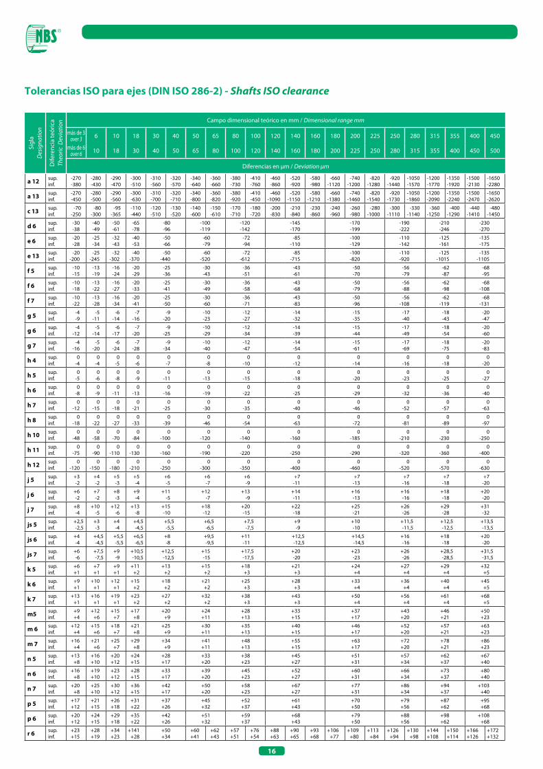
Tolerancias ISO para ejes (DIN ISO 286-2) - Shafts ISo clearance
Sigl
aD
esig
natio
n
Dife
renc
ia te
óric
aTh
eoric
Dev
iatio
n Campo dimensional teórico en mm / Dimensional range mm
más de 3over 3 6 10 18 30 40 50 65 80 100 120 140 160 180 200 225 250 280 315 355 400 450
más de 6over 6 10 18 30 40 50 65 80 100 120 140 160 180 200 225 250 280 315 355 400 450 500
Diferencias en μm / Deviation μm
a 12 sup.inf.
-270-380
-280-430
-290-470
-300-510
-310-560
-320-570
-340-640
-360-660
-380-730
-410-760
-460-860
-520-920
-580-980
-660-1120
-740-1200
-820-1280
-920-1440
-1050-1570
-1200-1770
-1350-1920
-1500-2130
-1650-2280
a 13 sup.inf.
-270-450
-280-500
-290-560
-300-630
-310-700
-320-710
-340-800
-360-820
-380-920
-410-450
-460-1090
-520-1150
-580-1210
-660-1380
-740-1460
-820-1540
-920-1730
-1050-1860
-1200-2090
-1350-2240
-1500-2470
-1650-2620
c 13 sup.inf.
-70-250
-80-300
-95-365
-110-440
-120-510
-130-520
-140-600
-150-610
-170-710
-180-720
-200-830
-210-840
-230-860
-240-960
-260-980
-280-1000
-300-1110
-330-1140
-360-1250
-400-1290
-440-1410
-480-1450
d 6 sup.inf.
-30-38
-40-49
-50-61
-65-78
-80-96
-100-119
-120-142
-145-170
-170-199
-190-222
-210-246
-230-270
e 6 sup.inf.
-20-28
-25-34
-32-43
-40-53
-50-66
-60-79
-72-94
-85-110
-100-129
-110-142
-125-161
-135-175
e 13 sup.inf.
-20-200
-25-245
-32-302
-40-370
-50-440
-60-520
-72-612
-85-715
-100-820
-110-920
-125-1015
-135-1105
f 5 sup.inf.
-10-15
-13-19
-16-24
-20-29
-25-36
-30-43
-36-51
-43-61
-50-70
-56-79
-62-87
-68-95
f 6 sup.inf.
-10-18
-13-22
-16-27
-20-33
-25-41
-30-49
-36-58
-43-68
-50-79
-56-88
-62-98
-68-108
f 7 sup.inf.
-10-22
-13-28
-16-34
-20-41
-25-50
-30-60
-36-71
-43-83
-50-96
-56-108
-62-119
-68-131
g 5 sup.inf.
-4-9
-5-11
-6-14
-7-16
-9-20
-10-23
-12-27
-14-32
-15-35
-17-40
-18-43
-20-47
g 6 sup.inf.
-4-12
-5-14
-6-17
-7-20
-9-25
-10-29
-12-34
-14-39
-15-44
-17-49
-18-54
-20-60
g 7 sup.inf.
-4-16
-5-20
-6-24
-7-28
-9-34
-10-40
-12-47
-14-54
-15-61
-17-69
-18-75
-20-83
h 4 sup.inf.
0-4
0-4
0-5
0-6
0-7
0-8
0-10
0-12
0-14
0-16
0-18
0-20
h 5 sup.inf.
0-5
0-6
0-8
0-9
0-11
0-13
0-15
0-18
0-20
0-23
0-25
0-27
h 6 sup.inf.
0-8
0-9
0-11
0-13
0-16
0-19
0-22
0-25
0-29
0-32
0-36
0-40
h 7 sup.inf.
0-12
0-15
0-18
0-21
0-25
0-30
0-35
0-40
0-46
0-52
0-57
0-63
h 8 sup.inf.
0-18
0-22
0-27
0-33
0-39
0-46
0-54
0-63
0-72
0-81
0-89
0-97
h 10 sup.inf.
0-48
0-58
0-70
0-84
0-100
0-120
0-140
0-160
0-185
0-210
0-230
0-250
h 11 sup.inf.
0-75
0-90
0-110
0-130
0-160
0-190
0-220
0-250
0-290
0-320
0-360
0-400
h 12 sup.inf.
0-120
0-150
0-180
0-210
0-250
0-300
0-350
0-400
0-460
0-520
0-570
0-630
j 5 sup.inf.
+3-2
+4-2
+5-3
+5-4
+6-5
+6-7
+6-9
+7-11
+7-13
+7-16
+7-18
+7-20
j 6 sup.inf.
+6-2
+7-2
+8-3
+9-4
+11-5
+12-7
+13-9
+14-11
+16-13
+16-16
+18-18
+20-20
j 7 sup.inf.
+8-4
+10-5
+12-6
+13-8
+15-10
+18-12
+20-15
+22-18
+25-21
+26-26
+29-28
+31-32
js 5 sup.inf.
+2,5-2,5
+3-3
+4-4
+4,5-4,5
+5,5-5,5
+6,5-6,5
+7,5-7,5
+9-9
+10-10
+11,5-11,5
+12,5-12,5
+13,5-13,5
js 6 sup.inf.
+4-4
+4,5-4,5
+5,5-5,5
+6,5-6,5
+8-8
+9,5-9,5
+11-11
+12,5-12,5
+14,5-14,5
+16-16
+18-18
+20-20
js 7 sup.inf.
+6-6
+7,5-7,5
+9-9
+10,5-10,5
+12,5-12,5
+15-15
+17,5-17,5
+20-20
+23-23
+26-26
+28,5-28,5
+31,5-31,5
k 5 sup.inf.
+6+1
+7+1
+9+1
+11+2
+13+2
+15+2
+18+3
+21+3
+24+4
+27+4
+29+4
+32+5
k 6 sup.inf.
+9+1
+10+1
+12+1
+15+2
+18+2
+21+2
+25+3
+28+3
+33+4
+36+4
+40+4
+45+5
k 7 sup.inf.
+13+1
+16+1
+19+1
+23+2
+27+2
+32+2
+38+3
+43+3
+50+4
+56+4
+61+4
+68+5
m5 sup.inf.
+9+4
+12+6
+15+7
+17+8
+20+9
+24+11
+28+13
+33+15
+37+17
+43+20
+46+21
+50+23
m 6 sup.inf.
+12+4
+15+6
+18+7
+21+8
+25+9
+30+11
+35+13
+40+15
+46+17
+52+20
+57+21
+63+23
m 7 sup.inf.
+16+4
+21+6
+25+7
+29+8
+34+9
+41+11
+48+13
+55+15
+63+17
+72+20
+78+21
+86+23
n 5 sup.inf.
+13+8
+16+10
+20+12
+24+15
+28+17
+33+20
+38+23
+45+27
+51+31
+57+34
+62+37
+67+40
n 6 sup.inf.
+16+8
+19+10
+23+12
+28+15
+33+17
+39+20
+45+23
+52+27
+60+31
+66+34
+73+37
+80+40
n 7 sup.inf.
+20+8
+25+10
+30+12
+36+15
+42+17
+50+20
+58+23
+67+27
+77+31
+86+34
+94+37
+103+40
p 5 sup.inf.
+17+12
+21+15
+26+18
+31+22
+37+26
+45+32
+52+37
+61+43
+70+50
+79+56
+87+62
+95+68
p 6 sup.inf.
+20+12
+24+15
+29+18
+35+22
+42+26
+51+32
+59+37
+68+43
+79+50
+88+56
+98+62
+108+68
r 6 sup.inf.
+23+15
+28+19
+34+23
+141+28
+50+34
+60+41
+62+43
+57+51
+76+54
+88+63
+90+65
+93+68
+106+77
+109+80
+113+84
+126+94
+130+98
+144+108
+150+114
+166+126
+172+132

17
Tipo de juego radial de los rodamientosTypes of radial clearance
Juego radial de los rodamientos de agujas y de rodillos cilíndricosRadial clearance of needle roller and cylindrical roller bearings
Uno de los principales factores que influencian en la durabilidad de los rodamientos de agujas es el juego radial, determinado como el valor medio de varias medidas del desplazamiento total sobre el plano perpendicular al eje del rodamiento. Dicho desplazamiento es típico de uno de los aros del rodamiento (el otro es estacionario) durante la rodadura en varias direcciones angulares, tanto respecto al aro rotativo como también respecto al estacionario y a diversas posiciones angulares de la serie de bolas o rodillos respecto a los aros mismos.Considerados los diversos coeficientes de juego requeridos en la entrega, los rodamientos rígidos se realizan según varios grupos de juego inicial. En general, los rodamientos de agujas se realizan según el grupo de juego radial normal CN, que, en empleos comunes en la mayor parte de los casos, suministran parámetros satisfactorios de funcionamiento. El juego radial se evidencia añadiendo la Designation de la clase de precisión (C2, C3, C4, C5) a la sigla del rodamiento mientras que a los rodamientos fabricados con un juego radial correspondiente al grupo normal no se les añaden otras designaciones convencionales. Las tablas que siguen a continuación muestran los valores de juego radial.
JUEGO RADIAL DE LOS RODAMIENTOS DE AGUJAS11
JUEGOCLEARANCE
C2
CN
C3
C4
Juego radial de los rodamientos inferiores a CNRadial clearance of bearings lower than CN
Juego radial de los rodamientos normalNormal radial clearance of bearings
Juego radial de los rodamientos superiores a CNRadial clearance of bearings higher than CN
Juego radial de los rodamientos superior a C3Radial clearance of bearings higher than C3
SIGNIFICADOMEANING
mín.de
from mín. mín. mín.máxato máx máx máx
C2
Juego radial (µm) - Radial clearance (µm)Diámetro orifi-cios (mm)
Bore diameter (mm) CN C3 C4
-24
304050
6580
100
120140160
180200225
250280315
355400450
2430
405065
80100120
140160180
200225250
280315355
400450500
00
55
10
101515
152025
354545
555565
100110100
2525
303540
455055
607075
90105110
125130145
190210220
2020
253040
405050
607075
90105110
125130145
190210220
4545
506070
758590
105120125
145165175
195205225
280310330
3535
455060
657585
100115120
140160170
190200225
280310330
6060
708090
100110125
145165170
195220235
260275305
370410440
5050
607080
90105125
145165170
195220235
260275305
370410440
7575
85100110
125140165
190215220
250280300
330350385
460510550
RADIAL CLEARANCE oF NEEDLE RoLLER BEARINGSOne of the most important factor influencing the life of a needle roller bearing, is the radial clearance.This is determined by a mean of several measurements of total displacement in the plane perpendicular to the bearing axle.This displacement is typical for one of the bearing ring (the other is stationary) during its rotation in different angular directions, both with respect to the rotable ring and the stationary one, and a different angular position of the set of balls or rollers, with respect to the bearing races.Because of the different requirements concerning the radial clearance, bearings are manufactured with several initial clearance groups, such as additional groups.Radial bearings are usually manufactured in accordance with the normal clearance group CN: this enables a satisfactory functioning of the bearing, in the majority of cases.Radial clearance is pointed out by adding the precision class (C2, C3, C4, C5) to bearing group.No further conventional designation are assigned to normal clearance bearings.Values of radial clearances are given below, see tables.
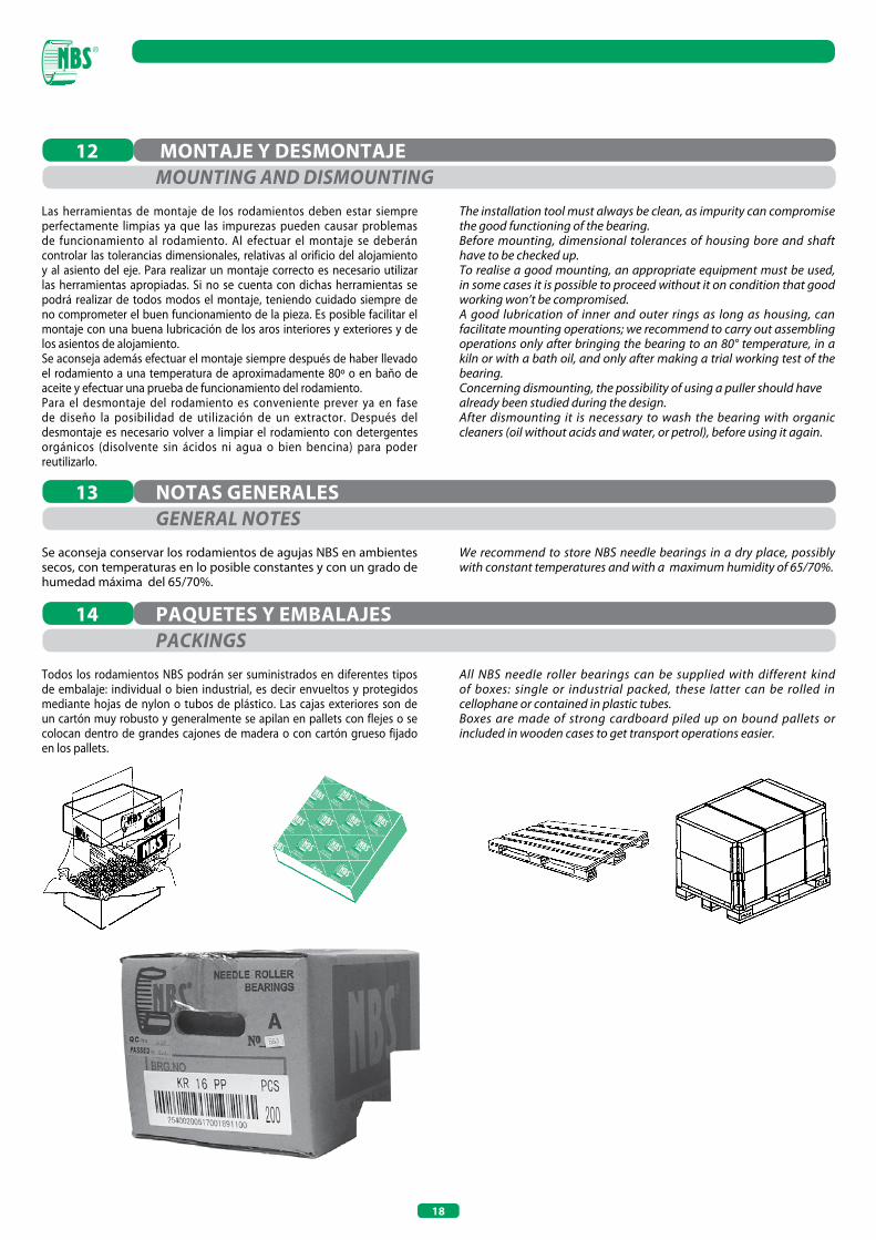
18
Las herramientas de montaje de los rodamientos deben estar siempre perfectamente limpias ya que las impurezas pueden causar problemas de funcionamiento al rodamiento. Al efectuar el montaje se deberán controlar las tolerancias dimensionales, relativas al orificio del alojamiento y al asiento del eje. Para realizar un montaje correcto es necesario utilizar las herramientas apropiadas. Si no se cuenta con dichas herramientas se podrá realizar de todos modos el montaje, teniendo cuidado siempre de no comprometer el buen funcionamiento de la pieza. Es posible facilitar el montaje con una buena lubricación de los aros interiores y exteriores y de los asientos de alojamiento. Se aconseja además efectuar el montaje siempre después de haber llevado el rodamiento a una temperatura de aproximadamente 80º o en baño de aceite y efectuar una prueba de funcionamiento del rodamiento.Para el desmontaje del rodamiento es conveniente prever ya en fase de diseño la posibilidad de utilización de un extractor. Después del desmontaje es necesario volver a limpiar el rodamiento con detergentes orgánicos (disolvente sin ácidos ni agua o bien bencina) para poder reutilizarlo.
Se aconseja conservar los rodamientos de agujas NBS en ambientes secos, con temperaturas en lo posible constantes y con un grado de humedad máxima del 65/70%.
Todos los rodamientos NBS podrán ser suministrados en diferentes tipos de embalaje: individual o bien industrial, es decir envueltos y protegidos mediante hojas de nylon o tubos de plástico. Las cajas exteriores son de un cartón muy robusto y generalmente se apilan en pallets con flejes o se colocan dentro de grandes cajones de madera o con cartón grueso fijado en los pallets.
MONTAJE y DESMONTAJE
NOTAS GENERALES
PAQUETES y EMBALAJES
12
13
14
MoUNTING AND DISMoUNTING
GENERAL NoTES
PACKINGS
The installation tool must always be clean, as impurity can compromise the good functioning of the bearing.Before mounting, dimensional tolerances of housing bore and shaft have to be checked up.To realise a good mounting, an appropriate equipment must be used, in some cases it is possible to proceed without it on condition that good working won’t be compromised.A good lubrication of inner and outer rings as long as housing, can facilitate mounting operations; we recommend to carry out assembling operations only after bringing the bearing to an 80° temperature, in a kiln or with a bath oil, and only after making a trial working test of the bearing.Concerning dismounting, the possibility of using a puIler should have already been studied during the design.After dismounting it is necessary to wash the bearing with organic cleaners (oil without acids and water, or petrol), before using it again.
We recommend to store NBS needle bearings in a dry place, possibly with constant temperatures and with a maximum humidity of 65/70%.
All NBS needIe roller bearings can be supplied with different kind of boxes: single or industrial packed, these latter can be rolled in cellophane or contained in plastic tubes.Boxes are made of strong cardboard piled up on bound pallets or included in wooden cases to get transport operations easier.

19
d diámetro nominal del orificio
Vdp variación del diámetro del orificio
Vdmp variación del diámetro medio del orificioΔ dmp diferencia del diámetro medio del orificio respecto al valor nominal
D diámetro nominal exterior
VDp variación del diámetro exterior
VDmp variación del diámetro exterior medio Δ Dmp diferencia del diámetro exterior medio respecto al valor nominal
Kia - Kea concentricidad de rotación del aro interior (Kia) o exterior (Kea) en el rodamiento ensamblado
B ancho del rodamiento Δ Bs - Δ Cs diferencia de una única medida del ancho del aro interior (ΔBs ) o exterior (ΔCs ) respecto a la dimensión nominal
VBs - VCs variación del ancho del aro interior (VBs) y exterior (VCs)
Sd defecto de cuadratura de las caras respecto al orificio (planeidad)
SD variación de la inclinación de la superficie cilíndrica exterior respecto a la superficie lateral
Si variación del espesor de una arandela para eje
Se variación del espesor de una arandela para alojamiento
T valor nominal de la altura de un rodamiento axial de simple efecto
d nominal bore diameter Vdp bore diameter variation Vdmp mean bore diameter variation Δ dmp deviation of the mean inner diameter from nominal value D nominal outer diameter VDp outer diameter variation VDmp mean outer diameter variation Δ Dmp deviation of the mean outer diameter from nominal value Kia - Kea concentricity radial run out of inner (Kia) and outer (Kea) ring of assembled bearing B bearing width Δ Bs - Δ Cs inner (ΔBs ) and outer ring (ΔCs ) single width deviation as regards to nominal dimension VBs - VCs width variation of inner (VBs) and outer (VCs) ring Sd side face run out with reference to bore of the inner ring (run out) SD variation in inclination of outside cylindrical surface to outer ring side face Si thickness variation of shaft locating washer Se thickness variation of housing locating washer T nominal bearing width of a single direction axial bearing
SÍMBOLOS y UNIDADES DE MEDIDA15ToLERANCE SYMBoLS AND DEFINITIoNS

20
DiseñoDrawing
Sigla Designation
DimensionesDimensions
PáginaPage
Jaulas de agujas de una y dos hileras (serie K - K..ZW)Needle roller and cage assemblies single/double crown (K - K..ZW series) 3-265 28-36
K K..ZW
Jaulas de agujas para articulaciones de bielas, soporte botón de manivela (serie KZK)Needle roller and cage assemblies for crank pin of connecting rod(KZK series)
8-40 40-41
KZK
Jaulas de agujas para articulaciones de bielas para soporte pasador (serie KBK)Needle roller and cage assemblies for piston pin of connecting rod(KBK series)
8-20 42-43
KBK
Jaulas de agujas lineales planas (serie GLP)Needle roller flat cage (GLP series) 20-40 48
GLP
Casquillos de agujas abiertos (serie HK)Drawn cup needle roller bearings open end (HK series) 3-60 52-53
HK
Casquillos de agujas con fondo (serie BK)Drawn cup needle roller bearings closed end (BK series) 3-60 52-53
BK
Casquillos de agujas con obturaciones (serie HK..RS..2RS)Sealed drawn cup needle roller bearings (HK..RS..2RS series) 8-50 54
HK..RS HK..2RS
Casquillos de agujas con fondo y obturaciones (serie BK..RS)Sealed drawn cup needle roller bearings closed end (BK..RS series) 14-25 54
BK..RS
Casquillos de agujas completamente llenos (serie HN)Drawn cup needle roller bearings full complement (HN series) 10-50 55
HN
Rodamientos de agujas sin aro interior (serie ligera NK)Needle roller bearings without inner ring (NK light series) 5-155 60-64
NK
Rodamientos de agujas sin aro interior (serie pesada NKS)Needle roller bearings without inner ring (NKS heavy series) 8-115 60-64
NKS
Rodamientos de agujas sin aro interior (serie RNA 49-RNA 48)Needle roller bearings without inner ring (RNA 49 - RNA 48 series) 14-415 60-64
RNA 49 - RNA 48
Rodamientos de agujas sin aro interior - de una o de dos hileras(serie RNA 69 - RNA 69..ZW)Needle roller bearings without inner ring - double row (RNA 69 series)
14-110 60-64
RNA 69 - RNA69..ZW
Rodamientos de agujas con aro interior (serie ligera NKI) Needle roller bearings with inner ring (NKI light series) 5-100 65-68
NKI
ÍNDICE GENERAL DE LOS PRODUCTOS 2PRoDUCTS GENERAL INDEX
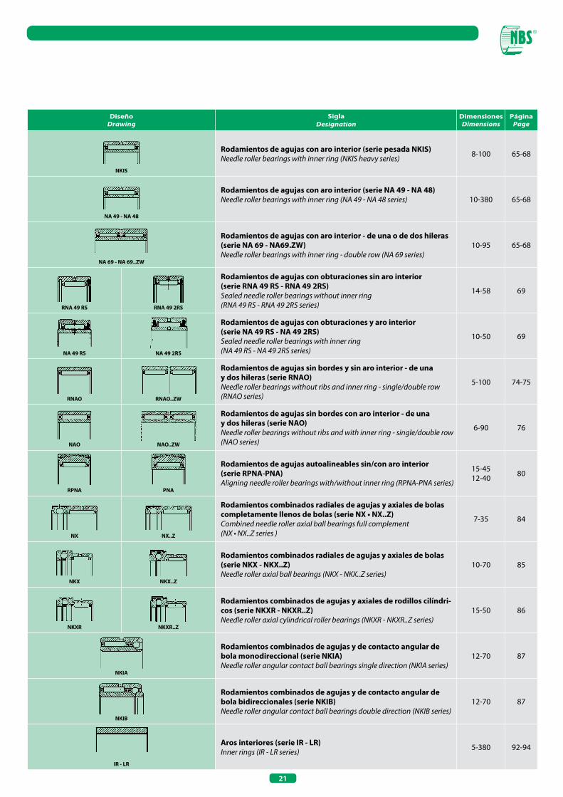
21
DiseñoDrawing
Sigla Designation
DimensionesDimensions
PáginaPage
Rodamientos de agujas con aro interior (serie pesada NKIS)Needle roller bearings with inner ring (NKIS heavy series) 8-100 65-68
NKIS
Rodamientos de agujas con aro interior (serie NA 49 - NA 48) Needle roller bearings with inner ring (NA 49 - NA 48 series) 10-380 65-68
NA 49 - NA 48
Rodamientos de agujas con aro interior - de una o de dos hileras(serie NA 69 - NA69.ZW)Needle roller bearings with inner ring - double row (NA 69 series)
10-95 65-68
NA 69 - NA 69..ZW
Rodamientos de agujas con obturaciones sin aro interior (serie RNA 49 RS - RNA 49 2RS)Sealed needle roller bearings without inner ring(RNA 49 RS - RNA 49 2RS series)
14-58 69
RNA 49 RS RNA 49 2RS
Rodamientos de agujas con obturaciones y aro interior(serie NA 49 RS - NA 49 2RS)Sealed needle roller bearings with inner ring(NA 49 RS - NA 49 2RS series)
10-50 69
NA 49 RS NA 49 2RS
Rodamientos de agujas sin bordes y sin aro interior - de unay dos hileras (serie RNAO)Needle roller bearings without ribs and inner ring - single/double row (RNAO series)
5-100 74-75
RNAO RNAO..ZW
Rodamientos de agujas sin bordes con aro interior - de unay dos hileras (serie NAO)Needle roller bearings without ribs and with inner ring - single/double row (NAO series)
6-90 76
NAO NAO..ZW
Rodamientos de agujas autoalineables sin/con aro interior(serie RPNA-PNA)Aligning needle roller bearings with/without inner ring (RPNA-PNA series)
15-4512-40 80
RPNA PNA
Rodamientos combinados radiales de agujas y axiales de bolas completamente llenos de bolas (serie NX • NX..Z)Combined needle roller axial ball bearings full complement(NX • NX..Z series )
7-35 84
Nx Nx..Z
Rodamientos combinados radiales de agujas y axiales de bolas (serie NKx - NKx..Z)Needle roller axial ball bearings (NKX - NKX..Z series)
10-70 85
NKx NKx..Z
Rodamientos combinados de agujas y axiales de rodillos cilíndri-cos (serie NKxR - NKxR..Z)Needle roller axial cylindrical roller bearings (NKXR - NKXR..Z series)
15-50 86
NKxR NKxR..Z
Rodamientos combinados de agujas y de contacto angular de bola monodireccional (serie NKIA)Needle roller angular contact ball bearings single direction (NKIA series)
12-70 87
NKIA
Rodamientos combinados de agujas y de contacto angular de bola bidireccionales (serie NKIB)Needle roller angular contact ball bearings double direction (NKIB series)
12-70 87
NKIB
Aros interiores (serie IR - LR)Inner rings (IR - LR series) 5-380 92-94
IR - LR
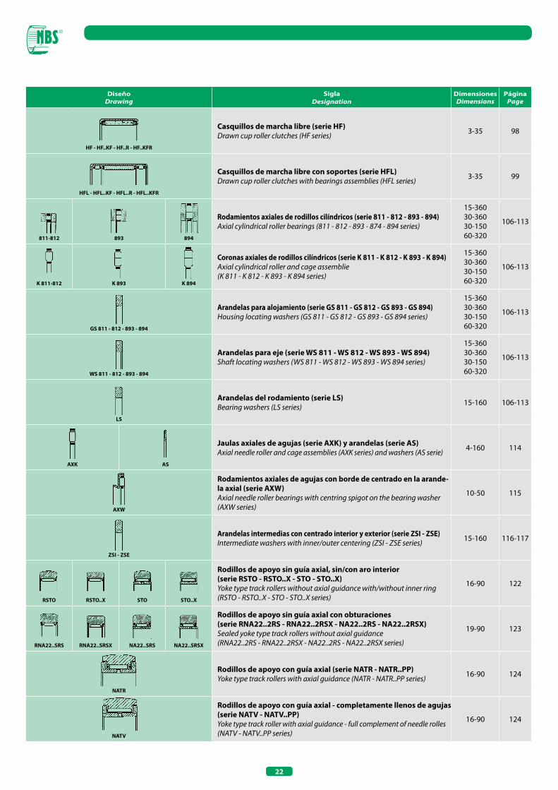
22
DiseñoDrawing
Sigla Designation
DimensionesDimensions
PáginaPage
Casquillos de marcha libre (serie HF)Drawn cup roller clutches (HF series) 3-35 98
HF - HF..KF - HF..R - HF..KFR
Casquillos de marcha libre con soportes (serie HFL)Drawn cup roller clutches with bearings assemblies (HFL series) 3-35 99
HFL - HFL..KF - HFL..R - HFL..KFR
Rodamientos axiales de rodillos cilíndricos (serie 811 - 812 - 893 - 894)Axial cylindrical roller bearings (811 - 812 - 893 - 874 - 894 series)
15-36030-36030-15060-320
106-113
811-812 893 894
Coronas axiales de rodillos cilíndricos (serie K 811 - K 812 - K 893 - K 894)Axial cylindrical roller and cage assemblie(K 811 - K 812 - K 893 - K 894 series)
15-36030-36030-15060-320
106-113
K 811-812 K 893 K 894
Arandelas para alojamiento (serie GS 811 - GS 812 - GS 893 - GS 894)Housing locating washers (GS 811 - GS 812 - GS 893 - GS 894 series)
15-36030-36030-15060-320
106-113
GS 811 - 812 - 893 - 894
Arandelas para eje (serie WS 811 - WS 812 - WS 893 - WS 894)Shaft locating washers (WS 811 - WS 812 - WS 893 - WS 894 series)
15-36030-36030-15060-320
106-113
WS 811 - 812 - 893 - 894
Arandelas del rodamiento (serie LS)Bearing washers (LS series) 15-160 106-113
LS
Jaulas axiales de agujas (serie AxK) y arandelas (serie AS) Axial needle roller and cage assemblies (AXK series) and washers (AS serie) 4-160 114
AxK AS
Rodamientos axiales de agujas con borde de centrado en la arande-la axial (serie AxW)Axial needle roller bearings with centring spigot on the bearing washer (AXW series)
10-50 115
AxW
Arandelas intermedias con centrado interior y exterior (serie ZSI - ZSE)Intermediate washers with inner/outer centering (ZSI - ZSE series) 15-160 116-117
ZSI - ZSE
Rodillos de apoyo sin guía axial, sin/con aro interior(serie RSTO - RSTO..x - STO - STO..x)Yoke type track rollers without axial guidance with/without inner ring(RSTO - RSTO..X - STO - STO..X series)
16-90 122
RSTO RSTO..x STO STO..x
Rodillos de apoyo sin guía axial con obturaciones(serie RNA22..2RS - RNA22..2RSx - NA22..2RS - NA22..2RSx)Sealed yoke type track rollers without axial guidance(RNA22..2RS - RNA22..2RSX - NA22..2RS - NA22..2RSX series)
19-90 123
RNA22..SRS RNA22..SRSx NA22..SRS NA22..SRSx
Rodillos de apoyo con guía axial (serie NATR - NATR..PP)Yoke type track rollers with axial guidance (NATR - NATR..PP series) 16-90 124
NATR
Rodillos de apoyo con guía axial - completamente llenos de agujas(serie NATV - NATV..PP)Yoke type track roller with axial guidance - full complement of needle rolles (NATV - NATV..PP series)
16-90 124
NATV
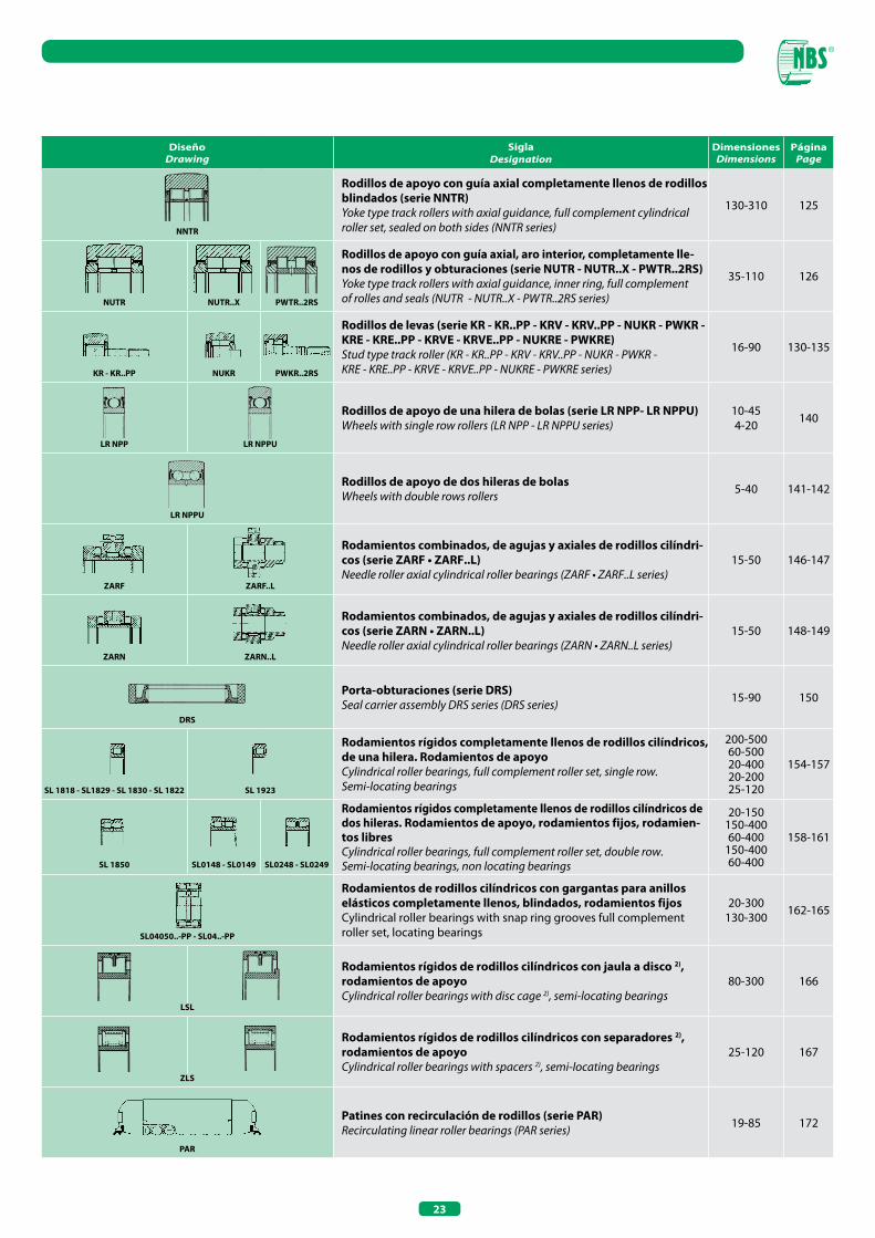
23
DiseñoDrawing
Sigla Designation
DimensionesDimensions
PáginaPage
Rodillos de apoyo con guía axial completamente llenos de rodillosblindados (serie NNTR)Yoke type track rollers with axial guidance, full complement cylindrical roller set, sealed on both sides (NNTR series)
130-310 125
NNTR
Rodillos de apoyo con guía axial, aro interior, completamente lle-nos de rodillos y obturaciones (serie NUTR - NUTR..x - PWTR..2RS)Yoke type track rollers with axial guidance, inner ring, full complementof rolles and seals (NUTR - NUTR..X - PWTR..2RS series)
35-110 126
NUTR NUTR..x PWTR..2RS
Rodillos de levas (serie KR - KR..PP - KRV - KRV..PP - NUKR - PWKR - KRE - KRE..PP - KRVE - KRVE..PP - NUKRE - PWKRE)Stud type track roller (KR - KR..PP - KRV - KRV..PP - NUKR - PWKR - KRE - KRE..PP - KRVE - KRVE..PP - NUKRE - PWKRE series)
16-90 130-135
KR - KR..PP NUKR PWKR..2RS
Rodillos de apoyo de una hilera de bolas (serie LR NPP- LR NPPU)Wheels with single row rollers (LR NPP - LR NPPU series)
10-454-20 140
LR NPP LR NPPU
Rodillos de apoyo de dos hileras de bolasWheels with double rows rollers 5-40 141-142
LR NPPU
Rodamientos combinados, de agujas y axiales de rodillos cilíndri-cos (serie ZARF • ZARF..L)Needle roller axial cylindrical roller bearings (ZARF • ZARF..L series)
15-50 146-147
ZARF ZARF..L
Rodamientos combinados, de agujas y axiales de rodillos cilíndri-cos (serie ZARN • ZARN..L)Needle roller axial cylindrical roller bearings (ZARN • ZARN..L series)
15-50 148-149
ZARN ZARN..L
Porta-obturaciones (serie DRS)Seal carrier assembly DRS series (DRS series) 15-90 150
DRS
Rodamientos rígidos completamente llenos de rodillos cilíndricos,de una hilera. Rodamientos de apoyoCylindrical roller bearings, full complement roller set, single row.Semi-locating bearings
200-50060-50020-40020-20025-120
154-157
SL 1818 - SL1829 - SL 1830 - SL 1822 SL 1923
Rodamientos rígidos completamente llenos de rodillos cilíndricos de dos hileras. Rodamientos de apoyo, rodamientos fijos, rodamien-tos libresCylindrical roller bearings, full complement roller set, double row.Semi-locating bearings, non locating bearings
20-150150-40060-400
150-40060-400
158-161
SL 1850 SL0148 - SL0149 SL0248 - SL0249
Rodamientos de rodillos cilíndricos con gargantas para anillos elásticos completamente llenos, blindados, rodamientos fijosCylindrical roller bearings with snap ring grooves full complementroller set, locating bearings
20-300130-300 162-165
SL04050..-PP - SL04..-PP
Rodamientos rígidos de rodillos cilíndricos con jaula a disco 2),rodamientos de apoyoCylindrical roller bearings with disc cage 2), semi-locating bearings
80-300 166
LSL
Rodamientos rígidos de rodillos cilíndricos con separadores 2),rodamientos de apoyoCylindrical roller bearings with spacers 2), semi-locating bearings
25-120 167
ZLS
Patines con recirculación de rodillos (serie PAR)Recirculating linear roller bearings (PAR series) 19-85 172
PAR
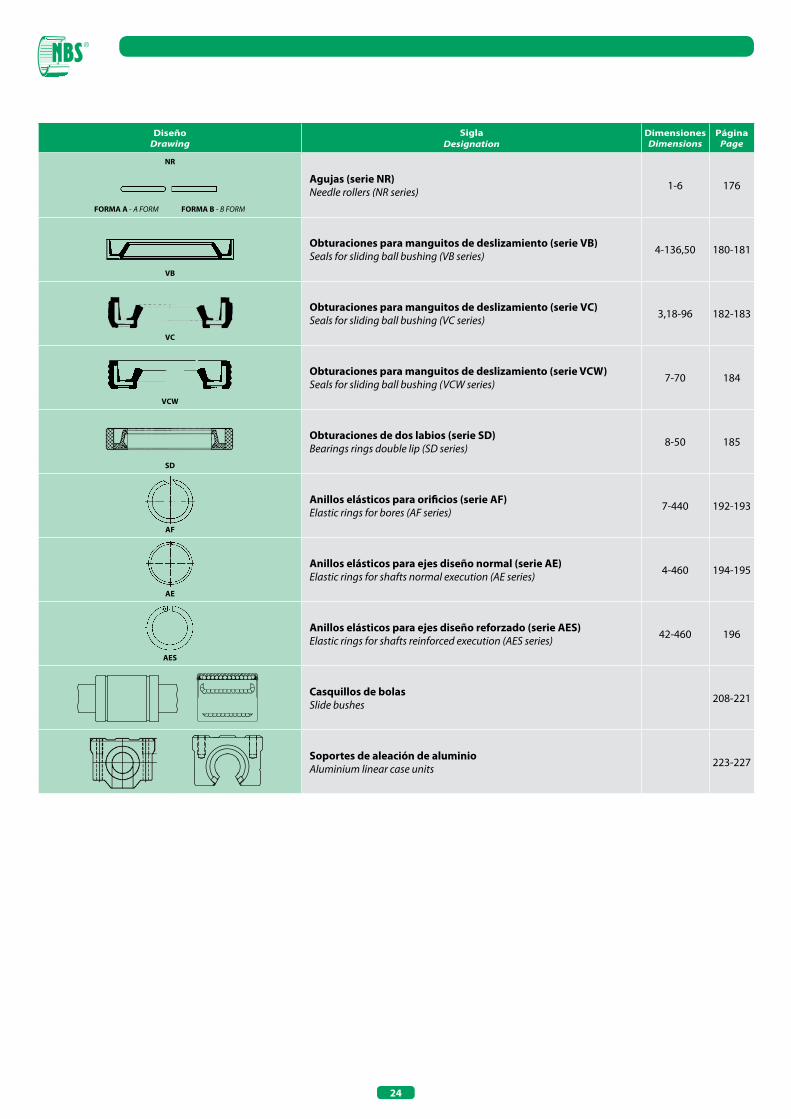
24
DiseñoDrawing
Sigla Designation
DimensionesDimensions
PáginaPage
NR
Agujas (serie NR)Needle rollers (NR series) 1-6 176
FORMA A - A FORM FORMA B - B FORM
Obturaciones para manguitos de deslizamiento (serie VB)Seals for sliding ball bushing (VB series) 4-136,50 180-181
VB
Obturaciones para manguitos de deslizamiento (serie VC)Seals for sliding ball bushing (VC series) 3,18-96 182-183
VC
Obturaciones para manguitos de deslizamiento (serie VCW)Seals for sliding ball bushing (VCW series) 7-70 184
VCW
Obturaciones de dos labios (serie SD)Bearings rings double lip (SD series) 8-50 185
SD
Anillos elásticos para orificios (serie AF)Elastic rings for bores (AF series) 7-440 192-193
AF
Anillos elásticos para ejes diseño normal (serie AE)Elastic rings for shafts normal execution (AE series) 4-460 194-195
AE
Anillos elásticos para ejes diseño reforzado (serie AES)Elastic rings for shafts reinforced execution (AES series) 42-460 196
AES
Casquillos de bolasSlide bushes 208-221
Soportes de aleación de aluminioAluminium linear case units 223-227
JAULAS DE AGUJASNEEDLE ROLLER AND CAGE ASSEMBLIES

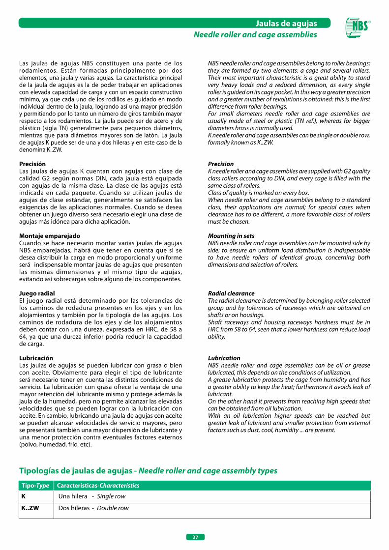
27
Jaulas de agujasNeedle roller and cage assemblies
Las jaulas de agujas NBS constituyen una parte de los rodamientos. Están formadas principalmente por dos elementos, una jaula y varias agujas. La característica principal de la jaula de agujas es la de poder trabajar en aplicaciones con elevada capacidad de carga y con un espacio constructivo mínimo, ya que cada uno de los rodillos es guidado en modo individual dentro de la jaula, logrando así una mayor precisión y permitiendo por lo tanto un número de giros también mayor respecto a los rodamientos. La jaula puede ser de acero y de plástico (sigla TN) generalmente para pequeños diámetros, mientras que para diámetros mayores son de latón. La jaula de agujas K puede ser de una y dos hileras y en este caso de la denomina K..ZW.
PrecisiónLas jaulas de agujas K cuentan con agujas con clase de calidad G2 según normas DIN, cada jaula está equipada con agujas de la misma clase. La clase de las agujas está indicada en cada paquete. Cuando se utilizan jaulas de agujas de clase estándar, generalmente se satisfacen las exigencias de las aplicaciones normales. Cuando se desea obtener un juego diverso será necesario elegir una clase de agujas más idónea para dicha aplicación.
Montaje emparejadoCuando se hace necesario montar varias jaulas de agujas NBS emparejadas, habrá que tener en cuenta que si se desea distribuir la carga en modo proporcional y uniforme será indispensable montar jaulas de agujas que presenten las mismas dimensiones y el mismo tipo de agujas, evitando así sobrecargas sobre alguno de los componentes.
Juego radialEl juego radial está determinado por las tolerancias de los caminos de rodadura presentes en los ejes y en los alojamientos y también por la tipología de las agujas. Los caminos de rodadura de los ejes y de los alojamientos deben contar con una dureza, expresada en HRC, de 58 a 64, ya que una dureza inferior podría reducir la capacidad de carga.
LubricaciónLas jaulas de agujas se pueden lubricar con grasa o bien con aceite. Obviamente para elegir el tipo de lubricante será necesario tener en cuenta las distintas condiciones de servicio. La lubricación con grasa ofrece la ventaja de una mayor retención del lubricante mismo y protege además la jaula de la humedad, pero no permite alcanzar las elevadas velocidades que se pueden lograr con la lubricación con aceite. En cambio, lubricando una jaula de agujas con aceite se pueden alcanzar velocidades de servicio mayores, pero se presentará también una mayor dispersión de lubricante y una menor protección contra eventuales factores externos (polvo, humedad, frío, etc).
Tipologías de jaulas de agujas - Needle roller and cage assembly types
K Una hilera - Single row
K..ZW Dos hileras - Double row
Tipo-Type Características-Characteristics
NBS needle roller and cage assemblies belong to roller bearings; they are formed by two elements: a cage and several rollers.Their most important characteristic is a great ability to stand very heavy loads and a reduced dimension, as every single roller is guided on its cage pocket. In this way a greater precision and a greater number of revolutions is obtained: this is the first difference from roller bearings.For small diameters needle roller and cage assemblies are usually made of steel or plastic (TN ref.), whereas for bigger diameters brass is normally used.K needle roller and cage assemblies can be single or double row, formally known as K..ZW.
PrecisionK needle roller and cage assemblies are supplied with G2 quality class rollers according to DIN, and every cage is filled with the same class of rollers.Class of quality is marked on every box.When needle roller and cage assemblies belong to a standard class, their applications are normal; for special cases when clearance has to be different, a more favorable class of rollers must be chosen.
Mounting in setsNBS needle roller and cage assemblies can be mounted side by side: to ensure an uniform load distribution is indispensable to have needle rollers of identical group, concerning both dimensions and selection of rollers.
Radial clearanceThe radial clearance is determined by belonging roller selected group and by tolerances of raceways which are obtained on shafts or on housings.Shaft raceways and housing raceways hardness must be in HRC from 58 to 64, seen that a lower hardness can reduce load ability.
LubricationNBS needle roller and cage assemblies can be oil or grease lubricated, this depends on the conditions of utilization.A grease lubrication protects the cage from humidity and has a greater ability to keep the heat; furthermore it avoids leak of lubricant.On the other hand it prevents from reaching high speeds that can be obtained from oil lubrication.With an oil lubrication higher speeds can be reached but greater leak of lubricant and smaller protection from external factors such us dust, cool, humidity ... are present.
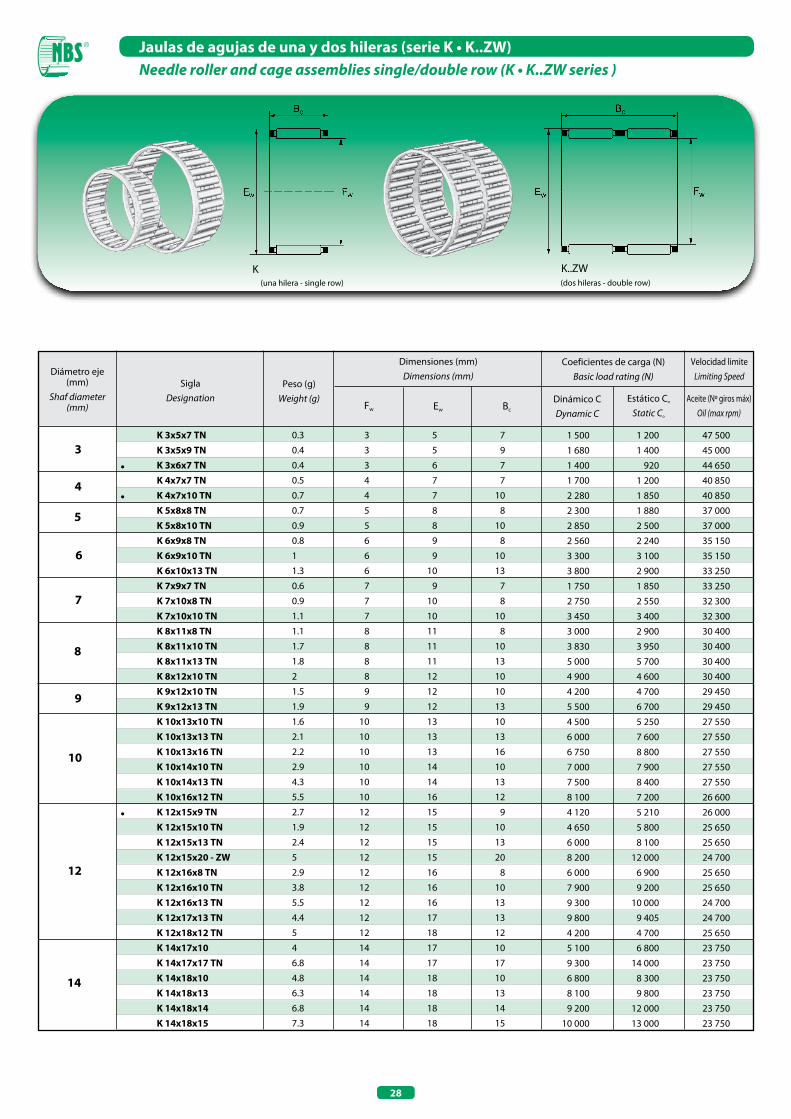
28
Jaulas de agujas de una y dos hileras (serie K • K..ZW)Needle roller and cage assemblies single/double row (K • K..ZW series )
(una hilera - single row)
K(dos hileras - double row)
K..ZW
Diámetro eje (mm)
Shaf diameter (mm)
SiglaDesignation
Peso (g)Weight (g)
Dimensiones (mm)Dimensions (mm)
Coeficientes de carga (N)Basic load rating (N)
Dinámico CDynamic C
Estático Co
Static Co
Fw Ew Bc
5
7
8
9
10
12
14
K 3x5x7 TN K 3x5x9 TN K 3x6x7 TN K 4x7x7 TN K 4x7x10 TN K 5x8x8 TN K 5x8x10 TN K 6x9x8 TN K 6x9x10 TN K 6x10x13 TN K 7x9x7 TN K 7x10x8 TN K 7x10x10 TN K 8x11x8 TN K 8x11x10 TN K 8x11x13 TN K 8x12x10 TN K 9x12x10 TN K 9x12x13 TN K 10x13x10 TN K 10x13x13 TN K 10x13x16 TN K 10x14x10 TN K 10x14x13 TN K 10x16x12 TN K 12x15x9 TN K 12x15x10 TN K 12x15x13 TN K 12x15x20 - ZW K 12x16x8 TN K 12x16x10 TN K 12x16x13 TN K 12x17x13 TN K 12x18x12 TN K 14x17x10 K 14x17x17 TN K 14x18x10 K 14x18x13 K 14x18x14 K 14x18x15
0.3
0.4
0.4
0.5
0.7
0.7
0.9
0.8
1
1.3
0.6
0.9
1.1
1.1
1.7
1.8
2
1.5
1.9
1.6
2.1
2.2
2.9
4.3
5.5
2.7
1.9
2.4
5
2.9
3.8
5.5
4.4
5
4
6.8
4.8
6.3
6.8
7.3
3 5 7
3 5 9
3 6 7
4 7 7
4 7 10
5 8 8
5 8 10
6 9 8
6 9 10
6 10 13
7 9 7
7 10 8
7 10 10
8 11 8
8 11 10
8 11 13
8 12 10
9 12 10
9 12 13
10 13 10
10 13 13
10 13 16
10 14 10
10 14 13
10 16 12
12 15 9
12 15 10
12 15 13
12 15 20
12 16 8
12 16 10
12 16 13
12 17 13
12 18 12
14 17 10
14 17 17
14 18 10
14 18 13
14 18 14
14 18 15
1 500 1 200 47 500
1 680 1 400 45 000
1 400 920 44 650
1 700 1 200 40 850
2 280 1 850 40 850
2 300 1 880 37 000
2 850 2 500 37 000
2 560 2 240 35 150
3 300 3 100 35 150
3 800 2 900 33 250
1 750 1 850 33 250
2 750 2 550 32 300
3 450 3 400 32 300
3 000 2 900 30 400
3 830 3 950 30 400
5 000 5 700 30 400
4 900 4 600 30 400
4 200 4 700 29 450
5 500 6 700 29 450
4 500 5 250 27 550
6 000 7 600 27 550
6 750 8 800 27 550
7 000 7 900 27 550
7 500 8 400 27 550
8 100 7 200 26 600
4 120 5 210 26 000
4 650 5 800 25 650
6 000 8 100 25 650
8 200 12 000 24 700
6 000 6 900 25 650
7 900 9 200 25 650
9 300 10 000 24 700
9 800 9 405 24 700
4 200 4 700 25 650
5 100 6 800 23 750
9 300 14 000 23 750
6 800 8 300 23 750
8 100 9 800 23 750
9 200 12 000 23 750
10 000 13 000 23 750
6
Aceite (Nº giros máx)Oil (max rpm)
Velocidad limiteLimiting Speed
•
•
•
3
4
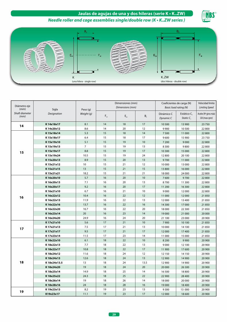
29
Jaulas de agujas de una y dos hileras (serie K • K..ZW)Needle roller and cage assemblies single/double row (K • K..ZW series )
(una hilera - single row)
K(dos hileras - double row)
K..ZW
15
16
17
18
19
14 K 14x18x17
K 14x20x12
K 15x18x14
K 15x18x17
K 15x19x10
K 15x19x13
K 15x19x17
K 15x19x24
K 15x20x13
K 15x21x12
K 15x21x15
K 15x21x21
K 16x20x10
K 16x20x13
K 16x20x17
K 16x21x10
K 16x22x12
K 16x22x13
K 16x22x16
K 16x22x20
K 16x23x14
K 16x24x20
K 17x21x10
K 17x21x13
K 17x21x17
K 17x23x14
K 18x22x10
K 18x22x13
K 18x22x17
K 18x24x12
K 18x24x13
K 18x24x13.5
K 18x24x20
K 18x25x14
K 18x25x22
K 18x26x14
K 18x28x16
K 19x23x13
K19x23x17
8.1
8.6
5.3
6.4
5.1
7
8.8
10.5
8.9
10
13
18.2
5.7
7.1
9.2
6.7
10.4
11.9
13.7
16.7
20
24.9
5.6
7.5
9.5
11.5
6.1
7.7
10.8
11.6
12.6
13
19
14.9
24.3
19
24
8.2
11.1
14 18 17
14 20 12
15 18 14
15 18 17
15 19 10
15 19 13
15 19 17
15 19 24
15 20 13
15 21 12
15 21 15
15 21 21
16 20 10
16 20 13
16 20 17
16 21 10
16 22 12
16 22 13
16 22 16
16 22 20
16 23 14
16 24 20
17 21 10
17 21 13
17 21 17
17 23 14
18 22 10
18 22 13
18 22 17
18 24 12
18 24 13
18 24 13.5
18 24 20
18 25 14
18 25 22
18 26 14
18 28 16
19 23 13
19 23 17
10 500 13 900 23 750
9 900 10 500 22 800
7 500 11 000 22 800
9 600 15 900 23 750
7 200 9 000 22 800
8 300 9 800 22 800
10 300 15 000 22 800
12 800 20 100 22 800
9 700 11 000 22 800
10 000 13 000 22 800
13 800 16 000 22 800
18 000 24 000 22 800
7 600 9 700 22 800
8 700 11 300 22 800
11 200 16 300 22 800
9 000 12 000 22 800
11 000 12 000 21 850
12 000 13 400 21 850
14 300 17 000 21 850
18 000 22 300 21 850
19 000 21 000 20 000
21 100 23 000 20 900
7 900 10 100 21 850
10 000 14 100 21 850
12 000 17 400 21 850
11 000 15 000 21 850
8 200 9 900 20 900
9 000 12 100 20 900
11 900 17 600 20 900
12 150 14 150 20 900
12 900 14 900 20 900
12 900 14 900 20 900
20 000 26 500 20 900
16 500 18 800 20 900
22 900 28 400 20 900
18 000 20 000 20 900
19 000 18 400 20 900
9 300 13 000 20 900
12 000 18 600 20 900
Diámetro eje (mm)
Shaft diameter (mm)
SiglaDesignation
Peso (g)Weight (g)
Dimensiones (mm)Dimensions (mm)
Coeficientes de carga (N)Basic load rating (N)
Dinámico CDynamic C
Estático Co
Static Co
Fw Ew Bc
Aceite (Nº giros máx)Oil (max rpm)
Velocidad limiteLimiting Speed
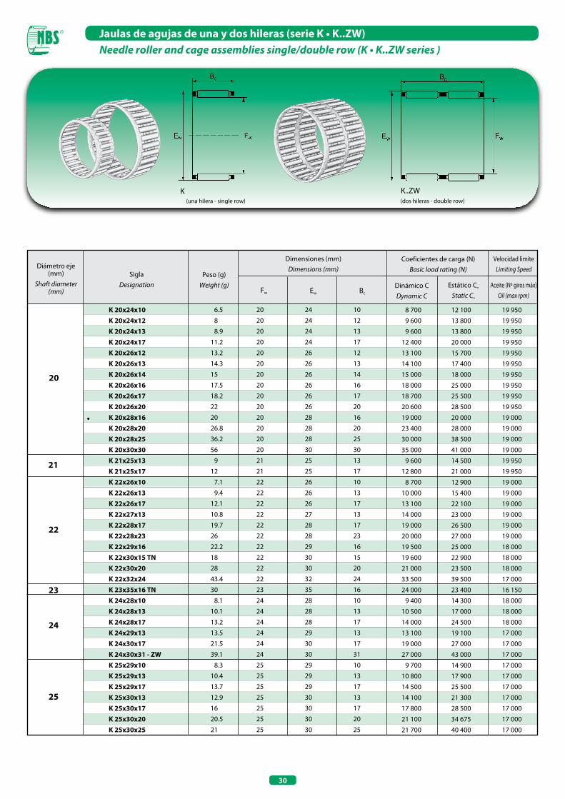
30
Jaulas de agujas de una y dos hileras (serie K • K..ZW)Needle roller and cage assemblies single/double row (K • K..ZW series )
(una hilera - single row)
K(dos hileras - double row)
K..ZW
20
22
24
K 20x24x10 K 20x24x12 K 20x24x13 K 20x24x17 K 20x26x12 K 20x26x13 K 20x26x14 K 20x26x16 K 20x26x17 K 20x26x20 K 20x28x16 K 20x28x20 K 20x28x25 K 20x30x30 K 21x25x13 K 21x25x17 K 22x26x10 K 22x26x13 K 22x26x17 K 22x27x13 K 22x28x17 K 22x28x23 K 22x29x16 K 22x30x15 TN K 22x30x20 K 22x32x24 K 23x35x16 TN K 24x28x10 K 24x28x13 K 24x28x17 K 24x29x13 K 24x30x17 K 24x30x31 - ZW K 25x29x10 K 25x29x13 K 25x29x17 K 25x30x13 K 25x30x17 K 25x30x20 K 25x30x25
6.5
8
8.9
11.2
13.2
14.3
15
17.5
18.2
22
20
26.8
36.2
56
9
12
7.1
9.4
12.1
10.8
19.7
26
22.2
18
28
43.4
30
8.1
10.1
13.2
13.5
21.5
39.1
8.3
10.4
13.7
12.9
16
20.5
21
20 24 10
20 24 12
20 24 13
20 24 17
20 26 12
20 26 13
20 26 14
20 26 16
20 26 17
20 26 20
20 28 16
20 28 20
20 28 25
20 30 30
21 25 13
21 25 17
22 26 10
22 26 13
22 26 17
22 27 13
22 28 17
22 28 23
22 29 16
22 30 15
22 30 20
22 32 24
23 35 16
24 28 10
24 28 13
24 28 17
24 29 13
24 30 17
24 30 31
25 29 10
25 29 13
25 29 17
25 30 13
25 30 17
25 30 20
25 30 25
21
23
25
•
Diámetro eje (mm)
Shaft diameter (mm)
SiglaDesignation
Peso (g)Weight (g)
Dimensiones (mm)Dimensions (mm)
Coeficientes de carga (N)Basic load rating (N)
Dinámico CDynamic C
Estático Co
Static Co
Fw Ew Bc
Aceite (Nº giros máx)Oil (max rpm)
Velocidad limiteLimiting Speed
8 700 12 100 19 950
9 600 13 800 19 950
9 600 13 800 19 950
12 400 20 000 19 950
13 100 15 700 19 950
14 100 17 400 19 950
15 000 18 000 19 950
18 000 25 000 19 950
18 700 25 500 19 950
20 600 28 500 19 950
19 000 20 000 19 000
23 400 28 000 19 000
30 000 38 500 19 000
35 000 41 000 19 000
9 600 14 500 19 950
12 800 21 000 19 950
8 700 12 900 19 000
10 000 15 400 19 000
13 100 22 100 19 000
14 000 23 000 19 000
19 000 26 500 19 000
20 000 27 000 19 000
19 500 25 000 18 000
19 600 22 900 18 000
21 000 23 500 18 000
33 500 39 500 17 000
24 000 23 400 16 150
9 400 14 300 18 000
10 500 17 000 18 000
14 000 24 500 18 000
13 100 19 100 17 000
19 000 27 000 17 000
27 000 43 000 17 000
9 700 14 900 17 000
10 800 17 900 17 000
14 500 25 500 17 000
14 100 21 300 17 000
17 800 28 500 17 000
21 100 34 675 17 000
21 700 40 400 17 000
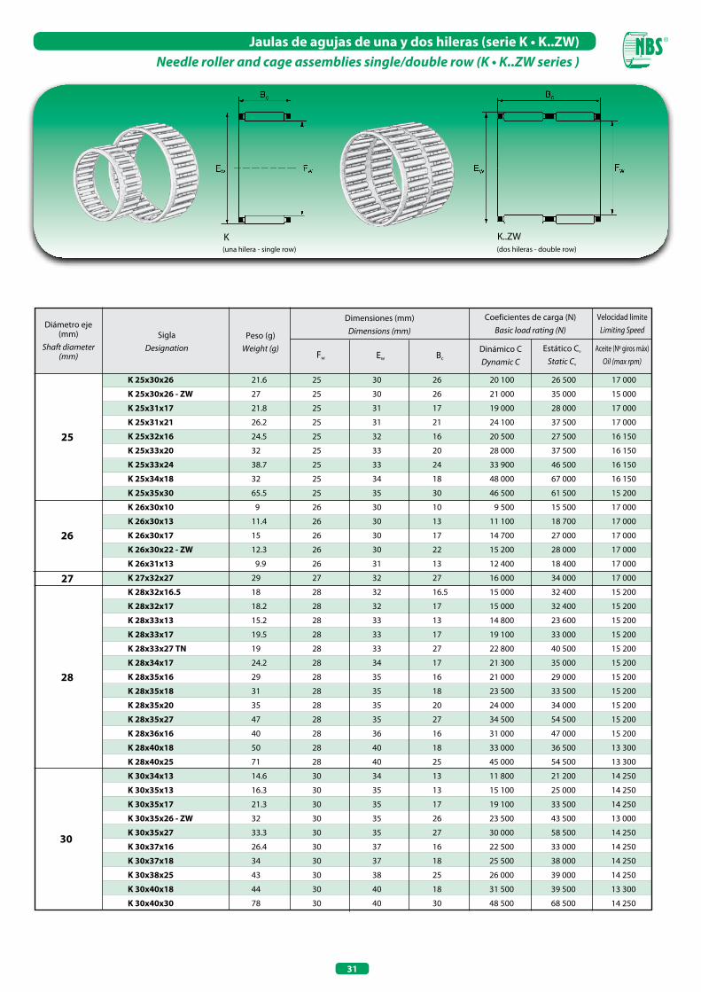
31
Jaulas de agujas de una y dos hileras (serie K • K..ZW)Needle roller and cage assemblies single/double row (K • K..ZW series )
(una hilera - single row)
K(dos hileras - double row)
K..ZW
25
27
K 25x30x26
K 25x30x26 - ZW
K 25x31x17
K 25x31x21
K 25x32x16
K 25x33x20
K 25x33x24
K 25x34x18
K 25x35x30
K 26x30x10
K 26x30x13
K 26x30x17
K 26x30x22 - ZW
K 26x31x13
K 27x32x27
K 28x32x16.5
K 28x32x17
K 28x33x13
K 28x33x17
K 28x33x27 TN
K 28x34x17
K 28x35x16
K 28x35x18
K 28x35x20
K 28x35x27
K 28x36x16
K 28x40x18
K 28x40x25
K 30x34x13
K 30x35x13
K 30x35x17
K 30x35x26 - ZW
K 30x35x27
K 30x37x16
K 30x37x18
K 30x38x25
K 30x40x18
K 30x40x30
21.6
27
21.8
26.2
24.5
32
38.7
32
65.5
9
11.4
15
12.3
9.9
29
18
18.2
15.2
19.5
19
24.2
29
31
35
47
40
50
71
14.6
16.3
21.3
32
33.3
26.4
34
43
44
78
25 30 26
25 30 26
25 31 17
25 31 21
25 32 16
25 33 20
25 33 24
25 34 18
25 35 30
26 30 10
26 30 13
26 30 17
26 30 22
26 31 13
27 32 27
28 32 16.5
28 32 17
28 33 13
28 33 17
28 33 27
28 34 17
28 35 16
28 35 18
28 35 20
28 35 27
28 36 16
28 40 18
28 40 25
30 34 13
30 35 13
30 35 17
30 35 26
30 35 27
30 37 16
30 37 18
30 38 25
30 40 18
30 40 30
20 100 26 500 17 000
21 000 35 000 15 000
19 000 28 000 17 000
24 100 37 500 17 000
20 500 27 500 16 150
28 000 37 500 16 150
33 900 46 500 16 150
48 000 67 000 16 150
46 500 61 500 15 200
9 500 15 500 17 000
11 100 18 700 17 000
14 700 27 000 17 000
15 200 28 000 17 000
12 400 18 400 17 000
16 000 34 000 17 000
15 000 32 400 15 200
15 000 32 400 15 200
14 800 23 600 15 200
19 100 33 000 15 200
22 800 40 500 15 200
21 300 35 000 15 200
21 000 29 000 15 200
23 500 33 500 15 200
24 000 34 000 15 200
34 500 54 500 15 200
31 000 47 000 15 200
33 000 36 500 13 300
45 000 54 500 13 300
11 800 21 200 14 250
15 100 25 000 14 250
19 100 33 500 14 250
23 500 43 500 13 000
30 000 58 500 14 250
22 500 33 000 14 250
25 500 38 000 14 250
26 000 39 000 14 250
31 500 39 500 13 300
48 500 68 500 14 250
26
28
30
Diámetro eje (mm)
Shaft diameter (mm)
SiglaDesignation
Peso (g)Weight (g)
Dimensiones (mm)Dimensions (mm)
Coeficientes de carga (N)Basic load rating (N)
Dinámico CDynamic C
Estático Co
Static Co
Fw Ew Bc
Aceite (Nº giros máx)Oil (max rpm)
Velocidad limiteLimiting Speed
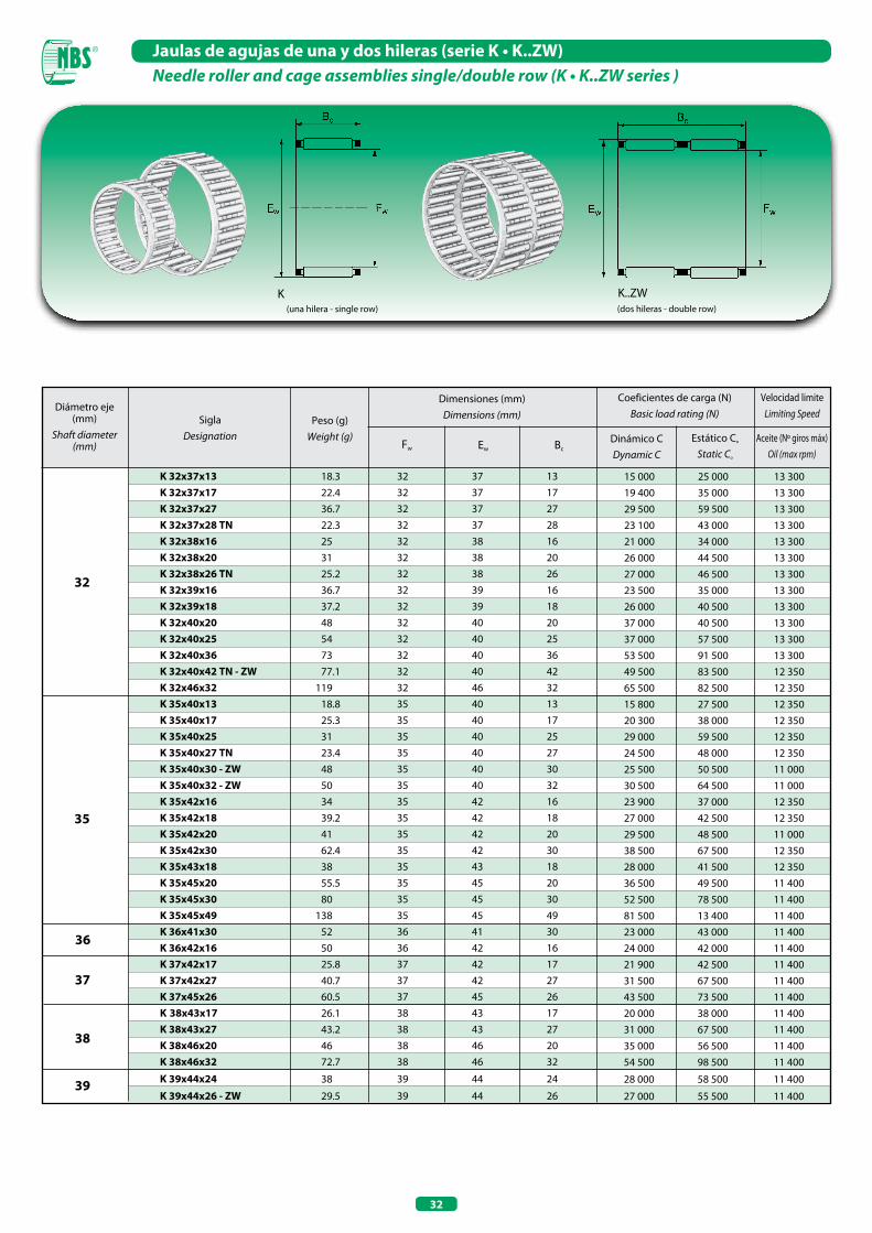
32
Jaulas de agujas de una y dos hileras (serie K • K..ZW)Needle roller and cage assemblies single/double row (K • K..ZW series )
(una hilera - single row)
K(dos hileras - double row)
K..ZW
35
32 37 13 32 37 17 32 37 27 32 37 28 32 38 16 32 38 20 32 38 26 32 39 16 32 39 18 32 40 20 32 40 25 32 40 36 32 40 42 32 46 32 35 40 13 35 40 17 35 40 25 35 40 27 35 40 30 35 40 32 35 42 16 35 42 18 35 42 20 35 42 30 35 43 18 35 45 20 35 45 30 35 45 49 36 41 30 36 42 16 37 42 17 37 42 27 37 45 26 38 43 17 38 43 27 38 46 20 38 46 32
39 44 24
39 44 26
32
36
37
38
39
Diámetro eje (mm)
Shaft diameter (mm)
SiglaDesignation
Peso (g)Weight (g)
Dimensiones (mm)Dimensions (mm)
Coeficientes de carga (N)Basic load rating (N)
Dinámico CDynamic C
Estático Co
Static Co
Fw Ew BcAceite (Nº giros máx)
Oil (max rpm)
Velocidad limiteLimiting Speed
15 000 25 000 13 300 19 400 35 000 13 300 29 500 59 500 13 300 23 100 43 000 13 300 21 000 34 000 13 300 26 000 44 500 13 300 27 000 46 500 13 300 23 500 35 000 13 300 26 000 40 500 13 300 37 000 40 500 13 300 37 000 57 500 13 300 53 500 91 500 13 300 49 500 83 500 12 350 65 500 82 500 12 350 15 800 27 500 12 350 20 300 38 000 12 350 29 000 59 500 12 350 24 500 48 000 12 350 25 500 50 500 11 000 30 500 64 500 11 000 23 900 37 000 12 350 27 000 42 500 12 350 29 500 48 500 11 000 38 500 67 500 12 350 28 000 41 500 12 350 36 500 49 500 11 400 52 500 78 500 11 400 81 500 13 400 11 400 23 000 43 000 11 400 24 000 42 000 11 400 21 900 42 500 11 400 31 500 67 500 11 400 43 500 73 500 11 400 20 000 38 000 11 400 31 000 67 500 11 400 35 000 56 500 11 400 54 500 98 500 11 400
28 000 58 500 11 400
27 000 55 500 11 400
K 32x37x13 K 32x37x17 K 32x37x27 K 32x37x28 TN K 32x38x16 K 32x38x20 K 32x38x26 TN K 32x39x16 K 32x39x18 K 32x40x20 K 32x40x25 K 32x40x36 K 32x40x42 TN - ZW K 32x46x32 K 35x40x13 K 35x40x17 K 35x40x25 K 35x40x27 TN K 35x40x30 - ZW K 35x40x32 - ZW K 35x42x16 K 35x42x18 K 35x42x20 K 35x42x30 K 35x43x18 K 35x45x20 K 35x45x30 K 35x45x49 K 36x41x30 K 36x42x16 K 37x42x17 K 37x42x27 K 37x45x26 K 38x43x17 K 38x43x27 K 38x46x20 K 38x46x32
K 39x44x24
K 39x44x26 - ZW
18.3 22.4 36.7 22.3 25 31 25.2 36.7 37.2 48 54 73 77.1 119 18.8 25.3 31 23.4 48 50 34 39.2 41 62.4 38 55.5 80 138 52 50 25.8 40.7 60.5 26.1 43.2 46 72.7
38
29.5
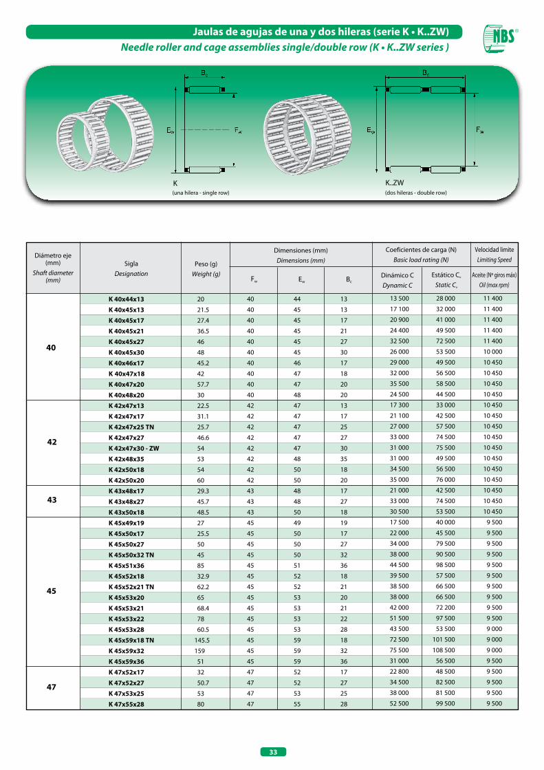
33
Jaulas de agujas de una y dos hileras (serie K • K..ZW)Needle roller and cage assemblies single/double row (K • K..ZW series )
(una hilera - single row)
K(dos hileras - double row)
K..ZW
40
43
K 40x44x13
K 40x45x13
K 40x45x17
K 40x45x21
K 40x45x27
K 40x45x30
K 40x46x17
K 40x47x18
K 40x47x20
K 40x48x20
K 42x47x13
K 42x47x17
K 42x47x25 TN
K 42x47x27
K 42x47x30 - ZW
K 42x48x35
K 42x50x18
K 42x50x20
K 43x48x17
K 43x48x27
K 43x50x18
K 45x49x19
K 45x50x17
K 45x50x27
K 45x50x32 TN
K 45x51x36
K 45x52x18
K 45x52x21 TN
K 45x53x20
K 45x53x21
K 45x53x22
K 45x53x28
K 45x59x18 TN
K 45x59x32
K 45x59x36
K 47x52x17
K 47x52x27
K 47x53x25
K 47x55x28
20
21.5
27.4
36.5
46
48
45.2
42
57.7
30
22.5
31.1
25.7
46.6
54
53
54
60
29.3
45.7
48.5
27
25.5
50
45
85
32.9
62.2
65
68.4
78
60.5
145.5
159
51
32
50.7
53
80
40 44 13
40 45 13
40 45 17
40 45 21
40 45 27
40 45 30
40 46 17
40 47 18
40 47 20
40 48 20
42 47 13
42 47 17
42 47 25
42 47 27
42 47 30
42 48 35
42 50 18
42 50 20
43 48 17
43 48 27
43 50 18
45 49 19
45 50 17
45 50 27
45 50 32
45 51 36
45 52 18
45 52 21
45 53 20
45 53 21
45 53 22
45 53 28
45 59 18
45 59 32
45 59 36
47 52 17
47 52 27
47 53 25
47 55 28
13 500 28 000 11 400
17 100 32 000 11 400
20 900 41 000 11 400
24 400 49 500 11 400
32 500 72 500 11 400
26 000 53 500 10 000
29 000 49 500 10 450
32 000 56 500 10 450
35 500 58 500 10 450
24 500 44 500 10 450
17 300 33 000 10 450
21 100 42 500 10 450
27 000 57 500 10 450
33 000 74 500 10 450
31 000 75 500 10 450
31 000 49 500 10 450
34 500 56 500 10 450
35 000 76 000 10 450
21 000 42 500 10 450
33 000 74 500 10 450
30 500 53 500 10 450
17 500 40 000 9 500
22 000 45 500 9 500
34 000 79 500 9 500
38 000 90 500 9 500
44 500 98 500 9 500
39 500 57 500 9 500
38 500 66 500 9 500
38 000 66 500 9 500
42 000 72 200 9 500
51 500 97 500 9 500
43 500 53 500 9 000
72 500 101 500 9 000
75 500 108 500 9 000
31 000 56 500 9 500
22 800 48 500 9 500
34 500 82 500 9 500
38 000 81 500 9 500
52 500 99 500 9 500
42
45
47
Diámetro eje (mm)
Shaft diameter (mm)
SiglaDesignation
Peso (g)Weight (g)
Dimensiones (mm)Dimensions (mm)
Coeficientes de carga (N)Basic load rating (N)
Dinámico CDynamic C
Estático Co
Static Co
Fw Ew BcAceite (Nº giros máx)
Oil (max rpm)
Velocidad limiteLimiting Speed
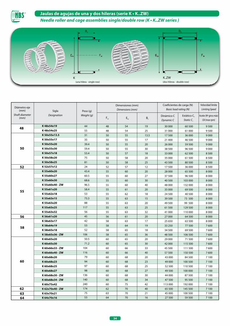
34
Jaulas de agujas de una y dos hileras (serie K • K..ZW)Needle roller and cage assemblies single/double row (K • K..ZW series )
(una hilera - single row)
K(dos hileras - double row)
K..ZW
48
55
K 48x54x19
K 48x54x25
K 50x55x13.5
K 50x55x17
K 50x55x20
K 50x55x30
K 50x57x18
K 50x58x20
K 50x58x25
K 52x57x12
K 55x60x20
K 55x60x27
K 55x60x30
K 55x60x40 - ZW
K 55x61x20
K 55x62x18
K 55x63x15
K 55x63x20
K 55x63x25
K 55x63x32
K 56x61x20
K 58x63x17
K 58x64x19
K 58x65x18
K 58x65x36 - ZW
K 60x65x20
K 60x65x30
K 60x66x33 - ZW
K 60x66x40 - ZW
K 60x68x20
K 60x68x23
K 60x68x25
K 60x68x27
K 60x68x30 - ZW
K 60x68x34 - ZW
K 60x75x42
K 62x70x40 - ZW
K 63x70x21 K 64x70x16
48 54 19
48 54 25
50 55 13.5
50 55 17
50 55 20
50 55 30
50 57 18
50 58 20
50 58 25
52 57 12
55 60 20
55 60 27
55 60 30
55 60 40
55 61 20
55 62 18
55 63 15
55 63 20
55 63 25
55 63 32
56 61 20
58 63 17
58 64 19
58 65 18
58 65 36
60 65 20
60 65 30
60 66 33
60 66 40
60 68 20
60 68 23
60 68 25
60 68 27
60 68 30
60 68 34
60 75 42
62 70 40
63 70 21
64 70 16
30 000 60 500 9 500
31 000 61 000 9 500
17 500 36 000 9 000
21 400 46 500 9 000
26 000 59 500 9 000
38 500 96 500 9 000
33 000 62 500 8 500
35 000 61 500 8 500
43 500 80 500 8 500
17 500 36 000 8 500
28 000 65 500 8 000
37 500 96 500 8 000
40 500 103 000 8 000
48 000 132 000 8 000
35 000 69 500 8 000
24 500 40 500 8 000
39 500 73 500 8 000
49 500 99 500 8 000
61 500 129 500 8 000
41 000 110 000 8 000
27 000 64 500 8 000
25 650 63 500 8 000
33 250 77 500 7 600
34 500 69 500 7 600
48 500 106 500 7 600
29 000 71 500 7 600
42 000 115 500 7 600
45 500 111 500 7 600
57 500 150 500 7 600
43 000 84 500 7 100
49 000 100 500 7 100
52 500 110 500 7 100
49 500 100 000 7 100
44 000 87 500 7 100
47 500 95 500 7 100
113 000 192 000 7 100
65 500 145 500 7 100
45 000 100 500 7 100
27 500 59 500 7 100
50
52
56
58
60
62 63 64
Diámetro eje (mm)
Shaft diameter (mm)
SiglaDesignation
Peso (g)Weight (g)
Dimensiones (mm)Dimensions (mm)
Coeficientes de carga (N)Basic load rating (N)
Dinámico CDynamic C
Estático Co
Static Co
Fw Ew Bc
Aceite (Nº giros máx)Oil (max rpm)
Velocidad limiteLimiting Speed
44
55
31
35
39.4
59.4
53.4
75
81
24
43.4
60.5
68.6
96.5
58.4
53
73.3
88
117
56
45
42
53
52
106
50.5
71.2
104
116
79
94
97
98
136
140
240
174
75
53
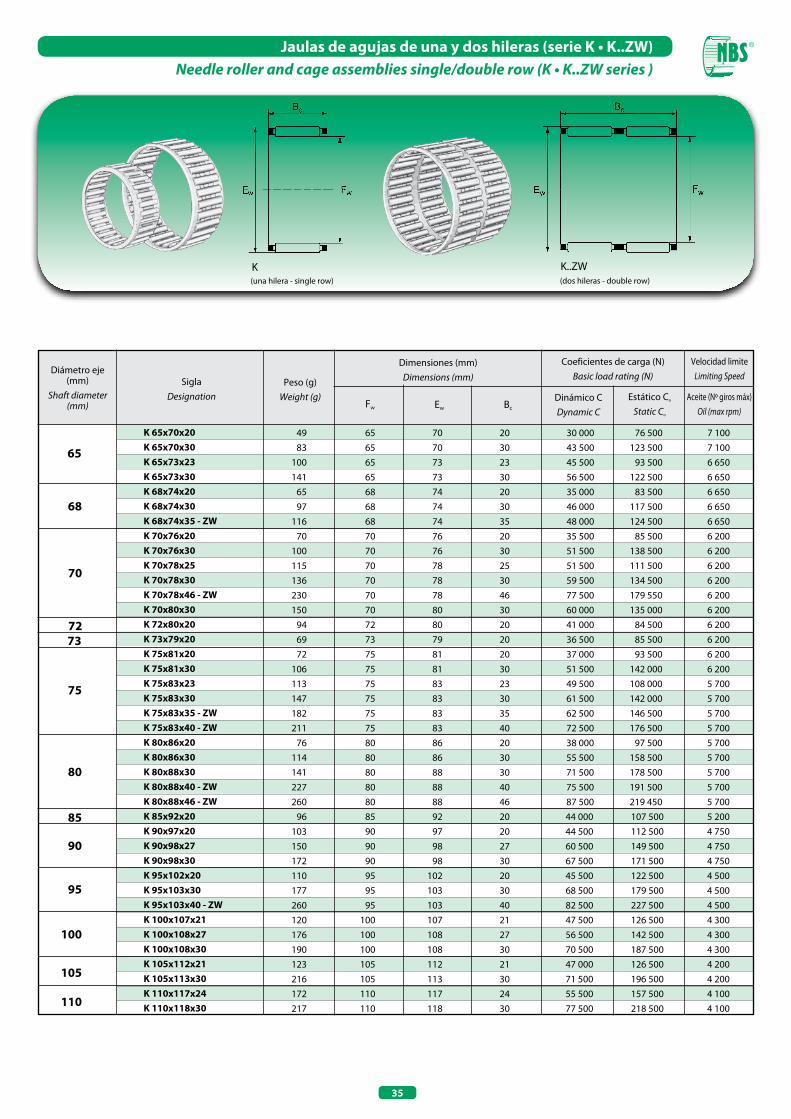
35
Jaulas de agujas de una y dos hileras (serie K • K..ZW)Needle roller and cage assemblies single/double row (K • K..ZW series )
(una hilera - single row)
K(dos hileras - double row)
K..ZW
68
72
K 65x70x20 K 65x70x30 K 65x73x23 K 65x73x30 K 68x74x20 K 68x74x30 K 68x74x35 - ZW K 70x76x20 K 70x76x30 K 70x78x25 K 70x78x30 K 70x78x46 - ZW K 70x80x30 K 72x80x20 K 73x79x20 K 75x81x20 K 75x81x30 K 75x83x23 K 75x83x30 K 75x83x35 - ZW K 75x83x40 - ZW K 80x86x20 K 80x86x30 K 80x88x30 K 80x88x40 - ZW K 80x88x46 - ZW K 85x92x20 K 90x97x20 K 90x98x27 K 90x98x30 K 95x102x20 K 95x103x30 K 95x103x40 - ZW K 100x107x21 K 100x108x27 K 100x108x30 K 105x112x21 K 105x113x30 K 110x117x24 K 110x118x30
49 83 100 141 65 97 116 70 100 115 136 230 150 94 69 72 106 113 147 182 211 76 114 141 227 260 96 103 150 172 110 177 260 120 176 190 123 216 172 217
65 70 20 65 70 30 65 73 23 65 73 30 68 74 20 68 74 30 68 74 35 70 76 20 70 76 30 70 78 25 70 78 30 70 78 46 70 80 30 72 80 20 73 79 20 75 81 20 75 81 30 75 83 23 75 83 30 75 83 35 75 83 40 80 86 20 80 86 30 80 88 30 80 88 40 80 88 46 85 92 20 90 97 20 90 98 27 90 98 30 95 102 20 95 103 30 95 103 40 100 107 21 100 108 27 100 108 30 105 112 21 105 113 30 110 117 24 110 118 30
30 000 76 500 7 100 43 500 123 500 7 100 45 500 93 500 6 650 56 500 122 500 6 650 35 000 83 500 6 650 46 000 117 500 6 650 48 000 124 500 6 650 35 500 85 500 6 200 51 500 138 500 6 200 51 500 111 500 6 200 59 500 134 500 6 200 77 500 179 550 6 200 60 000 135 000 6 200 41 000 84 500 6 200 36 500 85 500 6 200 37 000 93 500 6 200 51 500 142 000 6 200 49 500 108 000 5 700 61 500 142 000 5 700 62 500 146 500 5 700 72 500 176 500 5 700 38 000 97 500 5 700 55 500 158 500 5 700 71 500 178 500 5 700 75 500 191 500 5 700 87 500 219 450 5 700 44 000 107 500 5 200 44 500 112 500 4 750 60 500 149 500 4 750 67 500 171 500 4 750 45 500 122 500 4 500 68 500 179 500 4 500 82 500 227 500 4 500 47 500 126 500 4 300 56 500 142 500 4 300 70 500 187 500 4 300 47 000 126 500 4 200 71 500 196 500 4 200 55 500 157 500 4 100 77 500 218 500 4 100
65
70
73
75
80
85
90
95
100
105
110
Diámetro eje (mm)
Shaft diameter (mm)
SiglaDesignation
Peso (g)Weight (g)
Dimensiones (mm)Dimensions (mm)
Coeficientes de carga (N)Basic load rating (N)
Dinámico CDynamic C
Estático Co
Static Co
Fw Ew Bc
Aceite (Nº giros máx)Oil (max rpm)
Velocidad limiteLimiting Speed
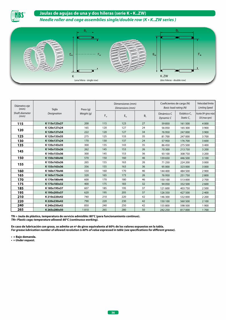
36
TN = Jaula de plástico, temperatura de servicio admisible: 80°C (para funcionamiento continuo).TN= Plastic cage; temperature allowed: 80°C (continuous working).
En caso de lubricación con grasa, se admite un nº de giros equivalente al 60% de los valores expuestos en la tabla.For grease lubrication number of allowed revolution is 60% of value expressed in table (see specifications for different grease).
• = Bajo demanda.• = Under request.
Jaulas de agujas de una y dos hileras (serie K • K..ZW)Needle roller and cage assemblies single/double row (K • K..ZW series )
(una hilera - single row)
K(dos hileras - double row)
K..ZW
120
145
150
160 165 170 175 185 195 210 220 240 265
155
K 115x123x27 K 120x127x24 K 120x127x34 K 125x133x35 K 130x137x24 K 135x143x35 K 145x153x26 K 145x153x36 K 150x160x46 K 155x163x26 K 155x163x36 K 160x170x46 K 165x173x26 K 170x180x46 K 175x183x32 K 185x195x37 K 195x205x37 K 210x220x42 K 220x230x42 K 240x250x42 K 265x280x50
200
165
222
275
170
300
262
300
570
265
356
550
320
600
400
607
620
740
790
850
1 810
115 123 27
120 127 24
120 127 34
125 133 35
130 137 24
135 143 35
145 153 26
145 153 36
150 160 46
155 163 26
155 163 36
160 170 46
165 173 26
170 180 46
175 183 32
185 195 37
195 205 37
210 220 42
220 230 42
240 250 42
265 280 50
59 850 161 500 4 000
56 050 165 300 3 900
76 950 247 000 3 900
81 700 247 000 3 700
57 950 176 700 3 600
86 450 275 500 3 400
70 300 213 750 3 200
93 100 308 750 3 200
139 650 446 500 3 100
71 250 224 200 3 000
95 000 323 000 3 000
144 400 484 500 2 900
76 950 251 750 2 800
150 100 513 000 2 700
94 050 332 500 2 600
121 600 403 750 2 500
126 350 427 500 2 400
146 300 532 000 2 200
150 100 560 500 2 100
155 800 598 500 1 900
242 250 817 000 1 700
115
125 130 135
Diámetro eje (mm)
Shaft diameter (mm)
SiglaDesignation
Peso (g)Weight (g)
Dimensiones (mm)Dimensions (mm)
Coeficientes de carga (N)Basic load rating (N)
Dinámico CDynamic C
Estático Co
Static Co
Fw Ew Bc
Aceite (Nº giros máx)Oil (max rpm)
Velocidad limiteLimiting Speed
JAULAS DE AGUJAS PARA ACOPLAMIENTO DE BIELASNEEDLE ROLLER AND CAGE ASSEMBLIES FOR
CONNECTING ROD BEARINGS ARRANGEMENTS


39
Jaulas de agujas para acoplamiento de bielasNeedle roller and cage assemblies for connecting rod bearings arrangements
Las jaulas de agujas para articulaciones de bielas se emplean generalmente en los mecanismos de levas de los motores de combustión interna. Han sido específicamente diseñadas para exigencias muy específicas, como por ejemplo fuerzas centrífugas y número de giros elevados. Existen dos tipos distintos de jaulas de agujas para acoplamientos de bielas, una está montada en el eje del motor y se denomina KZK, mientras que la otra está montada en la cabeza de la biela y se denomina KBK.
Jaulas de agujas (serie KZK)Se utilizan principalmente cuando existen fuerzas centrífugas muy elevadas. La jaula es guiada en el orificio de biela para limitar su juego y su movimiento. Las jaulas de agujas para acoplamientos de bielas cuentan con un tratamiento particular que les otorga una elevada resistencia y un desgaste mínimo. Tienen dimensiones reducidas lo que les permite alcanzar grandes velocidades.
Jaulas de agujas (serie KBK)Se utilizan principalmente cuando existen cargas oscilantes, están guiadas en el pasador con un juego radial muy limitado. Tienen en líneas generales las mismas características de las KZK.
The needle roller and cage assemblies for connecting rod, are particularly studied and employed in case of high number of revolutions or centrifugal forces: they are mounted in cranks of internal combustion engines.They are subdivided in two series: KZK for big end of the connecting rod, and KBK for connecting rod small ends.
Needle roller and cage assemblies (KZK series)Utilised when very high centrifugal forces are present, cage is guided on crank pin’s bore of connecting rod in order to avoid clearance and movement.These cages are treated in a particular way to obtain highest resistance and lowest wear; thanks to their small dimensions are able to reach high speeds.
Needle roller and cages assemblies (KBK series)Mainly requested in presence of oscillating loads and guided on piston pin, that have a very small radial clearance. For other characteristics, see KZK cages.
Ejemplo de montajeMounting example
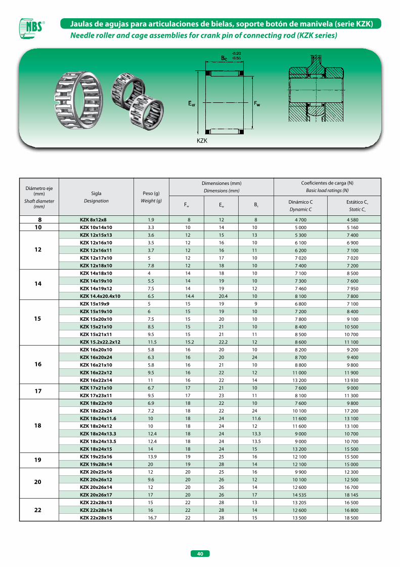
40
Jaulas de agujas para articulaciones de bielas, soporte botón de manivela (serie KZK)Needle roller and cage assemblies for crank pin of connecting rod (KZK series)
KZK
Diámetro eje (mm)
Shaft diameter (mm)
SiglaDesignation
Peso (g)Weight (g)
Dimensiones (mm)Dimensions (mm)
Coeficientes de carga (N)Basic load ratings (N)
Dinámico CDynamic C
Estático Co
Static Co
Fw Ew Bc
8
12
14
15
16
19
20
KZK 8x12x8 KZK 10x14x10 KZK 12x15x13 KZK 12x16x10 KZK 12x16x11 KZK 12x17x10 KZK 12x18x10 KZK 14x18x10 KZK 14x19x10 KZK 14x19x12 KZK 14.4x20.4x10 KZK 15x19x9 KZK 15x19x10 KZK 15x20x10 KZK 15x21x10 KZK 15x21x11 KZK 15.2x22.2x12 KZK 16x20x10 KZK 16x20x24 KZK 16x21x10 KZK 16x22x12 KZK 16x22x14 KZK 17x21x10 KZK 17x23x11 KZK 18x22x10 KZK 18x22x24 KZK 18x24x11.6 KZK 18x24x12 KZK 18x24x13.3 KZK 18x24x13.5 KZK 18x24x15 KZK 19x25x16 KZK 19x28x14 KZK 20x25x16 KZK 20x26x12 KZK 20x26x14 KZK 20x26x17 KZK 22x28x13 KZK 22x28x14 KZK 22x28x15
1.9
3.3
3.6
3.5
3.7
5
7.8
4
5.5
7.5
6.5
5
6
7.5
8.5
9.5
11.5
5.8
6.3
5.8
9.5
11
6.7
9.5
6.9
7.2
10
10
12.4
12.4
14
13.9
20
12
9.6
12
17
15
16
16.7
8 12 8
10 14 10
12 15 13
12 16 10
12 16 11
12 17 10
12 18 10
14 18 10
14 19 10
14 19 12
14.4 20.4 10
15 19 09
15 19 10
15 20 10
15 21 10
15 21 11
15.2 22.2 12
16 20 10
16 20 24
16 21 10
16 22 12
16 22 14
17 21 10
17 23 11
18 22 10
18 22 24
18 24 11.6
18 24 12
18 24 13.3
18 24 13.5
18 24 15
19 25 16
19 28 14
20 25 16
20 26 12
20 26 14
20 26 17
22 28 13
22 28 14
22 28 15
4 700 4 580
5 000 5 160
5 300 7 400
6 100 6 900
6 200 7 100
7 020 7 020
7 400 7 200
7 100 8 500
7 300 7 600
7 460 7 950
8 100 7 800
6 800 7 100
7 200 8 400
7 800 9 100
8 400 10 500
8 500 10 700
8 600 11 100
8 200 9 200
8 700 9 400
8 800 9 800
11 000 11 900
13 200 13 930
7 600 9 000
8 100 11 300
7 600 9 800
10 100 17 200
11 600 13 100
11 600 13 100
9 000 10 700
9 000 10 700
13 200 15 500
12 100 15 500
12 100 15 000
9 900 12 300
10 100 12 500
12 600 16 700
14 535 18 145
13 205 16 500
12 600 16 800
13 500 18 500
10
17
18
22
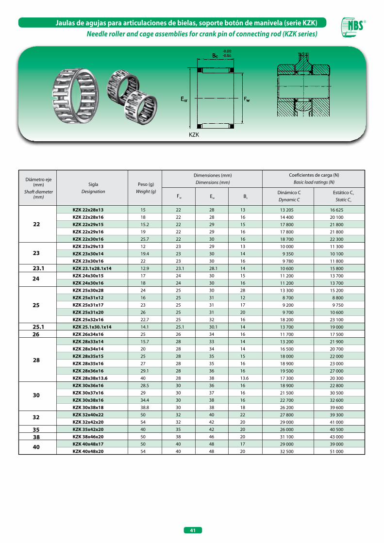
41
Jaulas de agujas para articulaciones de bielas, soporte botón de manivela (serie KZK)Needle roller and cage assemblies for crank pin of connecting rod (KZK series)
KZK
22
23
23.1
26
28
32
35
KZK 22x28x13 KZK 22x28x16 KZK 22x29x15 KZK 22x29x16 KZK 22x30x16 KZK 23x29x13 KZK 23x30x14 KZK 23x30x16 KZK 23.1x28.1x14 KZK 24x30x15 KZK 24x30x16 KZK 25x30x28 KZK 25x31x12 KZK 25x31x17 KZK 25x31x20 KZK 25x32x16 KZK 25.1x30.1x14 KZK 26x34x16 KZK 28x33x14 KZK 28x34x14 KZK 28x35x15 KZK 28x35x16 KZK 28x36x16 KZK 28x38x13.6 KZK 30x36x16 KZK 30x37x16 KZK 30x38x16 KZK 30x38x18 KZK 32x40x22 KZK 32x42x20 KZK 35x42x20 KZK 38x46x20 KZK 40x48x17 KZK 40x48x20
15
18
15.2
19
25.7
12
19.4
22
12.9
17
18
24
16
23
26
22.7
14.1
25
15.7
20
25
27
29.1
40
28.5
29
34.4
38.8
50
54
40
50
50
54
22 28 13
22 28 16
22 29 15
22 29 16
22 30 16
23 29 13
23 30 14
23 30 16
23.1 28.1 14
24 30 15
24 30 16
25 30 28
25 31 12
25 31 17
25 31 20
25 32 16
25.1 30.1 14
26 34 16
28 33 14
28 34 14
28 35 15
28 35 16
28 36 16
28 38 13.6
30 36 16
30 37 16
30 38 16
30 38 18
32 40 22
32 42 20
35 42 20
38 46 20
40 48 17
40 48 20
13 205 16 625
14 400 20 100
17 800 21 800
17 800 21 800
18 700 22 300
10 000 11 300
9 350 10 100
9 780 11 800
10 600 15 800
11 200 13 700
11 200 13 700
13 300 15 200
8 700 8 800
9 200 9 750
9 700 10 600
18 200 23 100
13 700 19 000
11 700 17 500
13 200 21 900
16 500 20 700
18 000 22 000
18 900 23 000
19 500 27 000
17 300 20 300
18 900 22 800
21 500 30 500
22 700 32 600
26 200 39 600
27 800 39 300
29 000 41 000
26 000 40 500
31 100 43 000
29 000 39 000
32 500 51 000
24
25
25.1
30
38
40
Diámetro eje (mm)
Shaft diameter (mm)
SiglaDesignation
Peso (g)Weight (g)
Dimensiones (mm)Dimensions (mm)
Coeficientes de carga (N)Basic load ratings (N)
Dinámico CDynamic C
Estático Co
Static Co
Fw Ew Bc
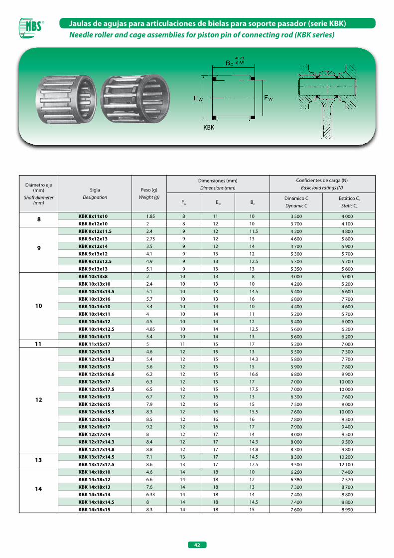
42
Jaulas de agujas para articulaciones de bielas para soporte pasador (serie KBK)Needle roller and cage assemblies for piston pin of connecting rod (KBK series)
KBK
8
9
10
11
12
13
14
KBK 8x11x10 KBK 8x12x10 KBK 9x12x11.5 KBK 9x12x13 KBK 9x12x14 KBK 9x13x12 KBK 9x13x12.5 KBK 9x13x13 KBK 10x13x8 KBK 10x13x10 KBK 10x13x14.5 KBK 10x13x16 KBK 10x14x10 KBK 10x14x11 KBK 10x14x12 KBK 10x14x12.5 KBK 10x14x13 KBK 11x15x17 KBK 12x15x13 KBK 12x15x14.3 KBK 12x15x15 KBK 12x15x16.6 KBK 12x15x17 KBK 12x15x17.5 KBK 12x16x13 KBK 12x16x15 KBK 12x16x15.5 KBK 12x16x16 KBK 12x16x17 KBK 12x17x14 KBK 12x17x14.3 KBK 12x17x14.8 KBK 13x17x14.5 KBK 13x17x17.5 KBK 14x18x10 KBK 14x18x12 KBK 14x18x13 KBK 14x18x14 KBK 14x18x14.5 KBK 14x18x15
1.85
2
2.4
2.75
3.5
4.1
4.9
5.1
2
2.4
5.1
5.7
3.4
4
4.5
4.85
5.4
5
4.6
5.4
5.6
6.2
6.3
6.5
6.7
7.9
8.3
8.5
9.2
8
8.4
8.8
7.1
8.6
4.6
6.6
7.6
6.33
8
8.3
8 11 10
8 12 10
9 12 11.5
9 12 13
9 12 14
9 13 12
9 13 12.5
9 13 13
10 13 8
10 13 10
10 13 14.5
10 13 16
10 14 10
10 14 11
10 14 12
10 14 12.5
10 14 13
11 15 17
12 15 13
12 15 14.3
12 15 15
12 15 16.6
12 15 17
12 15 17.5
12 16 13
12 16 15
12 16 15.5
12 16 16
12 16 17
12 17 14
12 17 14.3
12 17 14.8
13 17 14.5
13 17 17.5
14 18 10
14 18 12
14 18 13
14 18 14
14 18 14.5
14 18 15
3 500 4 000
3 700 4 100
4 200 4 800
4 600 5 800
4 700 5 900
5 300 5 700
5 300 5 700
5 350 5 600
4 000 5 000
4 200 5 200
5 400 6 600
6 800 7 700
4 400 4 600
5 200 5 700
5 400 6 000
5 600 6 200
5 600 6 200
5 200 7 000
5 500 7 300
5 800 7 700
5 900 7 800
6 800 9 900
7 000 10 000
7 000 10 000
6 300 7 600
7 500 9 000
7 600 10 000
7 800 9 300
7 900 9 400
8 000 9 500
8 000 9 500
8 300 9 800
8 300 10 200
9 500 12 100
6 260 7 400
6 380 7 570
7 300 8 700
7 400 8 800
7 400 8 800
7 600 8 990
Diámetro eje (mm)
Shaft diameter (mm)
SiglaDesignation
Peso (g)Weight (g)
Dimensiones (mm)Dimensions (mm)
Coeficientes de carga (N)Basic load ratings (N)
Dinámico CDynamic C
Estático Co
Static Co
Fw Ew Bc
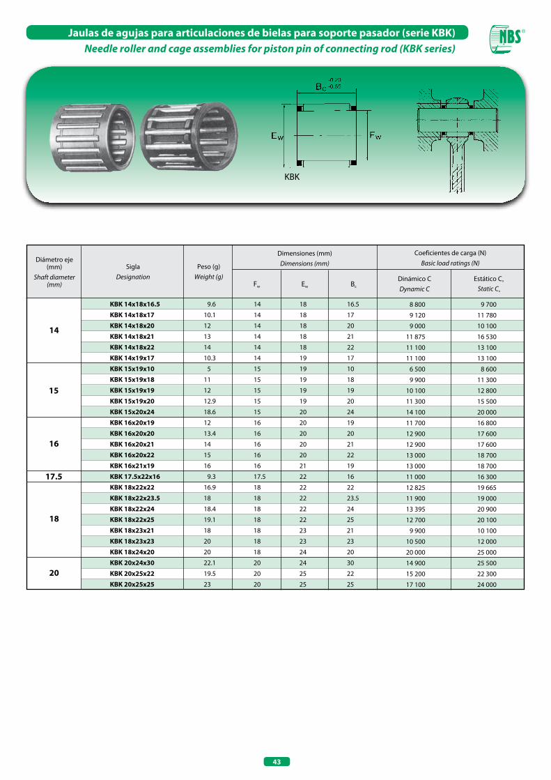
43
Jaulas de agujas para articulaciones de bielas para soporte pasador (serie KBK)Needle roller and cage assemblies for piston pin of connecting rod (KBK series)
KBK
KBK 14x18x16.5
KBK 14x18x17
KBK 14x18x20
KBK 14x18x21
KBK 14x18x22
KBK 14x19x17
KBK 15x19x10
KBK 15x19x18
KBK 15x19x19
KBK 15x19x20
KBK 15x20x24
KBK 16x20x19
KBK 16x20x20
KBK 16x20x21
KBK 16x20x22
KBK 16x21x19
KBK 17.5x22x16
KBK 18x22x22
KBK 18x22x23.5
KBK 18x22x24
KBK 18x22x25
KBK 18x23x21
KBK 18x23x23
KBK 18x24x20
KBK 20x24x30
KBK 20x25x22
KBK 20x25x25
14
18
15
16
17.5
20
9.6
10.1
12
13
14
10.3
5
11
12
12.9
18.6
12
13.4
14
15
16
9.3
16.9
18
18.4
19.1
18
20
20
22.1
19.5
23
14 18 16.5
14 18 17
14 18 20
14 18 21
14 18 22
14 19 17
15 19 10
15 19 18
15 19 19
15 19 20
15 20 24
16 20 19
16 20 20
16 20 21
16 20 22
16 21 19
17.5 22 16
18 22 22
18 22 23.5
18 22 24
18 22 25
18 23 21
18 23 23
18 24 20
20 24 30
20 25 22
20 25 25
8 800 9 700
9 120 11 780
9 000 10 100
11 875 16 530
11 100 13 100
11 100 13 100
6 500 8 600
9 900 11 300
10 100 12 800
11 300 15 500
14 100 20 000
11 700 16 800
12 900 17 600
12 900 17 600
13 000 18 700
13 000 18 700
11 000 16 300
12 825 19 665
11 900 19 000
13 395 20 900
12 700 20 100
9 900 10 100
10 500 12 000
20 000 25 000
14 900 25 500
15 200 22 300
17 100 24 000
Diámetro eje (mm)
Shaft diameter (mm)
SiglaDesignation
Peso (g)Weight (g)
Dimensiones (mm)Dimensions (mm)
Coeficientes de carga (N)Basic load ratings (N)
Dinámico CDynamic C
Estático Co
Static Co
Fw Ew Bc


JAULAS DE AGUJAS LINEALES PLANASNEEDLE ROLLER FLAT CAGES


47
Jaulas de agujas lineales planasNeedle roller flat cages
La característica principal de las jaulas de agujas lineales planas es la de estar compuestas por numerosos cuerpos rodantes, logrando así alcanzar capacidades de carga muy elevadas y notable precisión, ocupando un espacio mínimo.Este tipo particular de sistema se utiliza fundamentalmente en máquinas que requieren una elevada precisión.Las jaulas de agujas lineales planas están constituidas por guías de diferentes dimensiones, combinadas con jaulas planas. Los caminos de rodadura, para lograr un rendimiento lo más elevado posible, deberán tener necesariamente una dureza comprendida entre 58 y 64 HRC. En lo que se refiere a la precisión es necesario puntualizar que está supeditada a la alineación de las guías porque si éstas están perfectamente alineadas y tienen todas la misma longitud (en el caso de varios acoplamientos) se pueden alcanzar óptimos resultados de precisión y de silenciosidad y soportar a la vez elevadas cargas, gracias al elevado número de cuerpos rodantes.Las jaulas de agujas lineales planas presentan una fricción uniforme y baja. Dicha característica permite evitar el efecto “stick slip”. Es necesario recordar de todos modos que el coeficiente de fricción depende muchísimo de la precisión de montaje y de la lubricación.La lubricación podrá ser con grasa o con aceite; se aconseja utilizar lubricantes con aditivos.Es posible utilizar lubricación por goteo de aceite o niebla de aceite, esta última particularmente idónea en caso de ambientes con mucho polvo. Las jaulas de agujas lineales planas se suministran ya con una capa de lubricante y no necesitan grandes cantidades de lubricante.Es posible aplicar protecciones (rascadores) que garantizan un buen sellado contra eventuales impurezas externas. En caso de montaje de rascadores prestar mucha atención a que adhieran perfectamente a los caminos de rodadura en toda la longitud de su carrera.
Needle roller flat cages thanks to the needle rollers that form them, are able to stand very heavy loads and pressure, furthermore their dimension is really small.Their application is particularly required for machinery requiring very high precision; needle roller flat cages are formed by guidances which are different for their dimensions, that are combined with linear cages.Rolling grooves in order to obtain highest performances, should have an hardness included between 58 and 64 HRC.Concerning precision, we have to point out the fact that it is determined by guides alignement: if they are perfectly lined up and have the same length, in case of multiple coupling they can reach best performances concerning precision in sliding and noise; besides thanks to their many needle roller bearings are able to stand very heavy loads.Needle roller flat cages have an uniform and low friction, this avoids “stick slip” effect anyway we have to say that friction coefficient depends on mounting precision and lubrication.Lubrication can b e effec tued with oi l o r g rea s e,further additives can successfully be used; “drip feed lubrication” system or “fog oil” system is particularly suitable for dusty places.Needle roller flat cages are already prelubricated and do not need high quantity of lubricant.Protections against external factors can be applied (oil seals): in this case the oil seals have to perfectly adhered on rolling grooves for the all length.
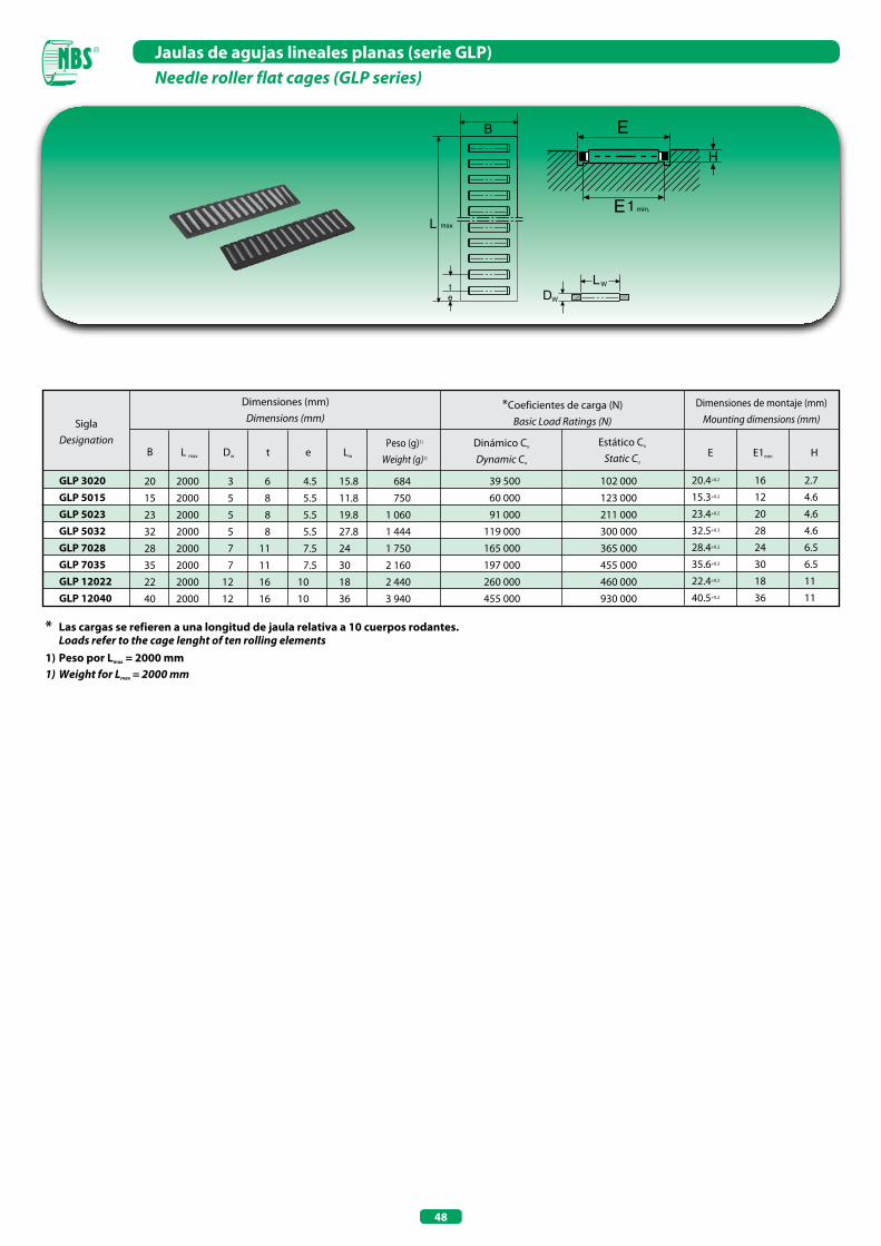
48
Jaulas de agujas lineales planas (serie GLP)NeedIe roller flat cages (GLP series)
B
L max
te
LW
DW
* Las cargas se refieren a una longitud de jaula relativa a 10 cuerpos rodantes. Loads refer to the cage lenght of ten rolling elements1) Peso por Lmax = 2000 mm 1) Weight for Lmax = 2000 mm
SiglaDesignation
Dimensiones (mm)Dimensions (mm)
Dimensiones de montaje (mm)Mounting dimensions (mm)
B
20 2000 3 6 4.5 15.8 684
15 2000 5 8 5.5 11.8 750
23 2000 5 8 5.5 19.8 1 060
32 2000 5 8 5.5 27.8 1 444
28 2000 7 11 7.5 24 1 750
35 2000 7 11 7.5 30 2 160
22 2000 12 16 10 18 2 440
40 2000 12 16 10 36 3 940
39 500 102 000
60 000 123 000
91 000 211 000
119 000 300 000
165 000 365 000
197 000 455 000
260 000 460 000
455 000 930 000
L max Dw t e Lw
Peso (g)1)
Weight (g)1)
*Coeficientes de carga (N)Basic Load Ratings (N)
Dinámico Co
Dynamic Co
Estático Co
Static Co
E E1min H
20.4+0.2 16 2.7
15.3+0.2 12 4.6
23.4+0.2 20 4.6
32.5+0.3 28 4.6
28.4+0.2 24 6.5
35.6+0.3 30 6.5
22.4+0.2 18 11
40.5+0.2 36 11
GLP 3020GLP 5015GLP 5023GLP 5032GLP 7028GLP 7035GLP 12022GLP 12040
mín.
E
E1
H
CASQUILLOS DE AGUJAS ABIERTOS
CASQUILLOS DE AGUJAS CON FONDO
DRAWN CUP NEEDLE ROLLER BEARINGS OPEN END
DRAWN CUP NEEDLE ROLLER BEARINGS CLOSED END

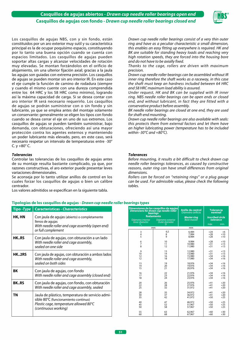
51
Casquillos de agujas abiertos - Drawn cup needle roller bearings open endCasquillos de agujas con fondo - Drawn cup needle roller bearings closed end
Los casquillos de agujas NBS, con y sin fondo, están constituidos por un aro exterior muy sutil y su característica principal es la de ocupar poquísimo espacio, constituyendo por lo tanto una buena opción cuando se cuenta con espacios limitados. Los casquillos de agujas pueden soportar altas cargas y alcanzar velocidades de rotación muy elevadas. Se montan forzándolos en el orificio de alojamiento, sin una ulterior fijación axial; gracias a la jaula las agujas son guiadas con extrema precisión. Los casquillos de agujas se pueden montar sin aro interior IR. En este caso el eje cumple la función de camino de rodadura (siempre y cuando el mismo cuente con una dureza comprendida entre los 64 HRC y los 58 HRC como mínimo), logrando así la máxima capacidad de carga. Si se desea contar con aro interior IR será necesario requerirlo. Los casquillos de agujas se podrán suministrar con o sin fondo y sin lubricante, ya que se emplea antes del montaje solamente un conservante: generalmente se eligen los tipos con fondo cuando se desea cerrar el eje en uno de sus extremos. Los casquillos de agujas se pueden también suministrar, bajo demanda, con obturaciones, ofreciendo así una mayor protección contra los agentes externos y manteniendo un poder lubricante más elevado, pero, en este caso, será necesario respetar un intervalo de temperaturas entre -30° C. y +80° C.
ToleranciasControlar las tolerancias de los casquillos de agujas antes de su montaje resulta bastante complicado, ya que, por razones constructivas, el aro exterior puede presentar leves variaciones dimensionales. Se aconseja por lo tanto utilizar anillos de control en los cuales forzar los casquillos de agujas o bien un calibre centrador. Los valores admitidos se especifican en la siguiente tabla.
Tipologías de los casquillos de agujas - Drawn cup needle roller bearings types
Tipo -Type Características - Characteristics
HK, HN Con jaula de agujas (abierto) o completamente llenos de agujas
With needle roller and cage assembly (open end) or full complement
HK..RS Con jaula de agujas, con obturación a un lado With needle roller and cage assembly,
sealed on one side
HK..2RS Con jaula de agujas, con obturación a ambos lados With needle roller and cage assembly,
sealed on both sides
BK Con jaula de agujas, con fondo With needle roller and cage assembly (closed end)
BK..RS Con jaula de agujas, con fondo, con obturación With needle roller and cage assembly, sealed
TN Jaula de plástico, temperatura de servicio admi-sible 80°C (funcionamiento continuo)
Plastic cage, temperature allowed 80°C (continuous working)
Diámetro interiorInner diameter
Fw
Diámetro exteriorOuter diameter
D máx mín.
Dimensiones de los casquillos de agujasDimensions for drawn cup needle roller
bearingsAnillo de controlDiámetro orificio
Master ringBore master
Tolerancianominal
Inscribed circletolerance
Rodamiento
345
678
9101212
131415
161718
202225
283035
404550
5560
89
101112
13141618
192021
222324
262832
353742
475258
6368
+24+28+28
+28+31+31
+31+31+34+34
+34+34+34
+34+34+34
+41+41+41
+41+41+50
+50+50+50
+60+60
+6+10+10
+10+13+13
+13+13+16+16
+16+16+16
+16+16+16
+20+20+20
+20+20+25
+25+25+25
+30+30
6,4847,9848,984
9,98410,98011,980
12,98013,98015,98017,980
18,97619,97620,976
21,97622,97623,976
25,97627,97631,972
34,97236,97241,972
46,97251,96757,967
62,96767,967
mm mm6,5
Drawn cup needle roller bearings consist of a very thin outer ring and have as a peculiar characteristic a small dimension, this enables an easy fitting up everywhere is required. HK and BK are suitable for standing heavy loads and reaching very high rotation speeds, they are forced into the housing bore and do not have to be axially fixed.Thanks to the cage, rollers are driven with maximum precision.Drawn cup needle roller bearings can be assembled without IR inner ring therefore the shaft works as a raceway, in this case the shaft must keep an hardness included between 64 HRC and 58 HRC maximum load ability is assured.Under request, HK and BK can be supplied with IR inner ring. NBS needle roller bearings can be open ends or closed end, and without lubricant, in fact they are fitted with a conservative product before assembly.BK needle roller bearings are closed at one end, they are used for shaft-end mounting.Drawn cup needle roller bearings are also available with seals: this protects them from external factors and let them have an higher lubricating power (temperature has to be included within -30°C and +80°C).
TolerancesBefore mounting, it results a bit difficult to check drawn cup needle roller bearings tolerances, as caused by constructive reasons, outer ring can have small differences from original dimensions.Rollers can be forced on “retaining rings” or a plug gauge can be used. For admissible value, please check the following tables.
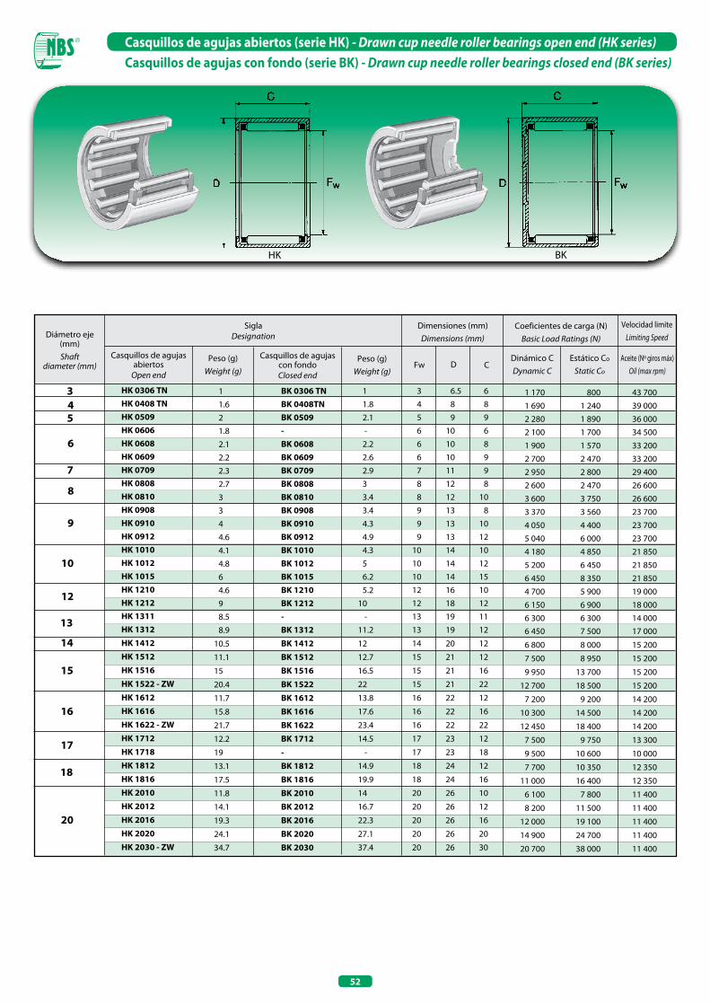
52
Casquillos de agujas abiertos (serie HK) - Drawn cup needle roller bearings open end (HK series)Casquillos de agujas con fondo (serie BK) - Drawn cup needle roller bearings closed end (BK series)
HK BK
Diámetro eje (mm) Shaft
diameter (mm)Peso (g)
Weight (g)Peso (g)
Weight (g)
Dimensiones (mm)Dimensions (mm)
Coeficientes de carga (N)Basic Load Ratings (N)
Dinámico CDynamic C
Estático Co
Static CoDFw C
Casquillos de agujas abiertos
Open end
Casquillos de agujas con fondoClosed end
SiglaDesignation
Aceite (Nº giros máx)Oil (max rpm)
Velocidad limiteLimiting Speed
4 5
6
9
7
8
10
12
13
3
15
14
16
17
18
20
HK 0306 TN HK 0408 TN HK 0509 HK 0606 HK 0608 HK 0609 HK 0709 HK 0808 HK 0810 HK 0908 HK 0910 HK 0912 HK 1010 HK 1012 HK 1015 HK 1210 HK 1212 HK 1311 HK 1312
HK 1412
HK 1512
HK 1516 HK 1522 - ZW
HK 1612
HK 1616 HK 1622 - ZW
HK 1712
HK 1718
HK 1812
HK 1816
HK 2010
HK 2012
HK 2016
HK 2020
HK 2030 - ZW
1
1.6
2
1.8
2.1
2.2
2.3
2.7
3
3
4
4.6
4.1
4.8
6
4.6
9
8.5
8.9
10.5
11.1
15
20.4
11.7
15.8
21.7
12.2
19
13.1
17.5
11.8
14.1
19.3
24.1
34.7
BK 0306 TN BK 0408TN BK 0509 - BK 0608 BK 0609 BK 0709 BK 0808 BK 0810 BK 0908 BK 0910 BK 0912 BK 1010 BK 1012 BK 1015 BK 1210 BK 1212 - BK 1312
BK 1412
BK 1512
BK 1516 BK 1522
BK 1612
BK 1616
BK 1622
BK 1712
-
BK 1812
BK 1816
BK 2010
BK 2012
BK 2016
BK 2020
BK 2030
1
1.8
2.1
-
2.2
2.6
2.9
3
3.4
3.4
4.3
4.9
4.3
5
6.2
5.2
10
-
11.2
12
12.7
16.5
22
13.8
17.6
23.4
14.5
-
14.9
19.9
14
16.7
22.3
27.1
37.4
3 6.5 6
4 8 8
5 9 9
6 10 6
6 10 8
6 10 9
7 11 9
8 12 8
8 12 10
9 13 8
9 13 10
9 13 12
10 14 10
10 14 12
10 14 15
12 16 10
12 18 12
13 19 11
13 19 12
14 20 12
15 21 12
15 21 16
15 21 22
16 22 12
16 22 16
16 22 22
17 23 12
17 23 18
18 24 12
18 24 16
20 26 10
20 26 12
20 26 16
20 26 20
20 26 30
1 170 800 43 700
1 690 1 240 39 000
2 280 1 890 36 000
2 100 1 700 34 500
1 900 1 570 33 200
2 700 2 470 33 200
2 950 2 800 29 400
2 600 2 470 26 600
3 600 3 750 26 600
3 370 3 560 23 700
4 050 4 400 23 700
5 040 6 000 23 700
4 180 4 850 21 850
5 200 6 450 21 850
6 450 8 350 21 850
4 700 5 900 19 000
6 150 6 900 18 000
6 300 6 300 14 000 6 450 7 500 17 000
6 800 8 000 15 200
7 500 8 950 15 200
9 950 13 700 15 200
12 700 18 500 15 200
7 200 9 200 14 200
10 300 14 500 14 200
12 450 18 400 14 200
7 500 9 750 13 300
9 500 10 600 10 000
7 700 10 350 12 350
11 000 16 400 12 350
6 100 7 800 11 400
8 200 11 500 11 400
12 000 19 100 11 400
14 900 24 700 11 400
20 700 38 000 11 400
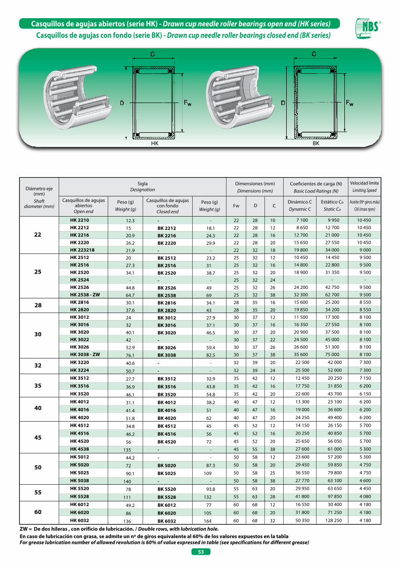
53
Casquillos de agujas abiertos (serie HK) - Drawn cup needle roller bearings open end (HK series)Casquillos de agujas con fondo (serie BK) - Drawn cup needle roller bearings closed end (BK series)
HK BK
En caso de lubricación con grasa, se admite un nº de giros equivalente al 60% de los valores expuestos en la tablaFor grease lubrication number of allowed revolution is 60% of value expressed in table (see specifications for different grease)
ZW = De dos hileras , con orificio de lubricación. / Double rows, with lubrication hole.
HK 2210 HK 2212 HK 2216 HK 2220 HK 223218 HK 2512 HK 2516 HK 2520 HK 2524 HK 2526 HK 2538 - ZW HK 2816 HK 2820 HK 3012 HK 3016 HK 3020 HK 3022 HK 3026 HK 3038 - ZW
HK 3220
HK 3224
HK 3512
HK 3516
HK 3520
HK 4012
HK 4016
HK 4020
HK 4512
HK 4516
HK 4520
HK 4538
HK 5012
HK 5020
HK 5025
HK 5038
HK 5520
HK 5528
HK 6012
HK 6020
HK 6032
12.3
15
20.9
26.2
21.9
20
27.3
34.1
-
44.8
64.7
30.1
37.6
24
32
40.1
42
52.9
76.1
40.6
50.7
27.7
36.9
46.1
31.1
41.4
51.8
34.8
46.2
56
135
44.2
72
90.1
140
78
111
49.2
86
136
- BK 2212 BK 2216 BK 2220 - BK 2512 BK 2516 BK 2520 - BK 2526 BK 2538 BK 2816 BK 2820 BK 3012 BK 3016 BK 3020 - BK 3026 BK 3038
-
-
BK 3512
BK 3516
BK 3520
BK 4012
BK 4016
BK 4020
BK 4512
BK 4516
BK 4520
-
-
BK 5020
BK 5025
-
BK 5520
BK 5528
BK 6012
BK 6020
BK 6032
-
18.1
24.3
29.9
-
23.2
31
38.7
-
49
69
34.1
43
27.9
37.1
46.5
-
59.4
82.5
-
-
32.9
43.8
54.8
38.2
51
62
45
56
72
-
-
87.3
109
-
93.8
132
77
105
164
22 28 10
22 28 12
22 28 16
22 28 20
22 32 18
25 32 12
25 32 16
25 32 20
25 32 24
25 32 26
25 32 38
28 35 16
28 35 20
30 37 12
30 37 16
30 37 20
30 37 22
30 37 26
30 37 38
32 39 20
32 39 24
35 42 12
35 42 16
35 42 20
40 47 12
40 47 16
40 47 20
45 52 12
45 52 16
45 52 20
45 55 38
50 58 12
50 58 20
50 58 25
50 58 38
55 63 20
55 63 28
60 68 12
60 68 20
60 68 32
7 100 9 950 10 450
8 650 12 700 10 450
12 700 21 000 10 450
15 650 27 550 10 450
19 800 34 000 9 000
10 450 14 450 9 500
14 800 22 800 9 500
18 900 31 350 9 500
- - -
24 200 42 750 9 500
32 300 62 700 9 500
15 600 25 200 8 550
19 850 34 200 8 550
11 500 17 300 8 100
16 350 27 550 8 100
20 900 37 500 8 100
24 500 45 000 8 100
26 600 51 300 8 100
35 600 75 000 8 100
22 500 42 000 7 300
25 500 52 000 7 300
12 450 20 250 7 150
17 750 31 850 6 200
22 600 43 700 6 150
13 300 23 100 6 200
19 000 36 600 6 200
24 250 49 400 6 200
14 150 26 150 5 700
20 250 40 850 5 700
25 650 56 050 5 700
27 600 61 000 5 300
23 600 57 200 5 300
29 450 59 850 4 750
36 550 79 800 4 750
27 770 63 100 4 600
29 950 63 650 4 450
41 800 97 850 4 080
16 550 30 400 4 180
31 800 71 250 4 180
50 350 128 250 4 180
22
25
28
30
32
35
40
45
50
55
60
Diámetro eje (mm) Shaft
diameter (mm)Peso (g)
Weight (g)Peso (g)
Weight (g)
Dimensiones (mm)Dimensions (mm)
Coeficientes de carga (N)Basic Load Ratings (N)
Dinámico CDynamic C
Estático Co
Static CoDFw C
Casquillos de agujas abiertos
Open end
Casquillos de agujas con fondoClosed end
SiglaDesignation
Aceite (Nº giros máx)Oil (max rpm)
Velocidad limiteLimiting Speed
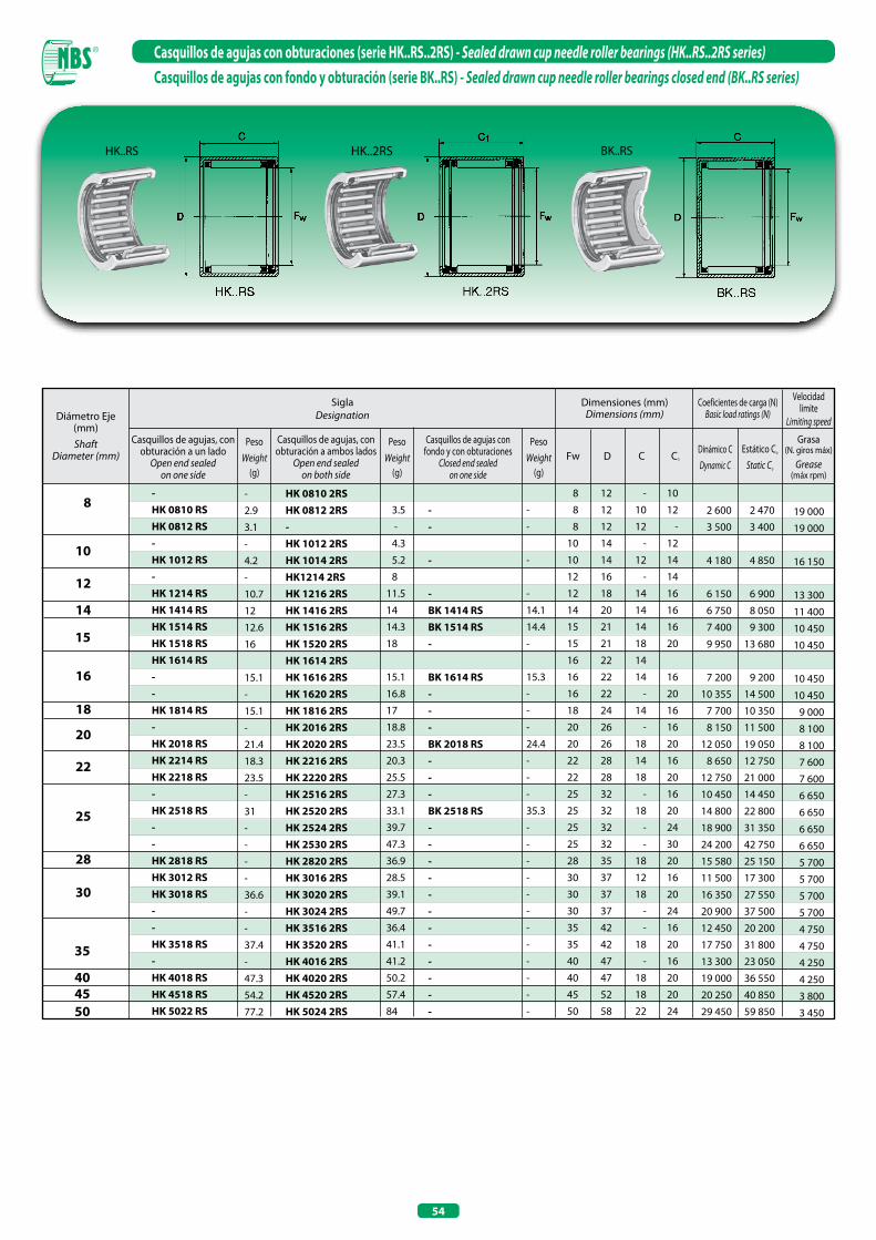
54
Casquillos de agujas con obturaciones (serie HK..RS..2RS) - Sealed drawn cup needle roller bearings (HK..RS..2RS series)Casquillos de agujas con fondo y obturación (serie BK..RS) - Sealed drawn cup needle roller bearings closed end (BK..RS series)
HK..RS HK..2RS BK..RS
Casquillos de agujas con fondo y con obturaciones
Closed end sealedon one side
Diámetro Eje (mm) Shaft
Diameter (mm)Peso
Weight(g)
Dimensiones (mm)Dimensions (mm)
Coeficientes de carga (N)Basic load ratings (N)
Dinámico CDynamic C
Estático Co
Static Co
DFw C
8
18
- HK 0810 RS HK 0812 RS - HK 1012 RS - HK 1214 RS HK 1414 RS HK 1514 RS HK 1518 RS HK 1614 RS - - HK 1814 RS - HK 2018 RS HK 2214 RS HK 2218 RS - HK 2518 RS - - HK 2818 RS HK 3012 RS HK 3018 RS - - HK 3518 RS - HK 4018 RS HK 4518 RS HK 5022 RS
-
2.9
3.1
-
4.2
-
10.7
12
12.6
16
15.1
-
15.1
-
21.4
18.3
23.5
-
31
-
-
-
-
36.6
-
-
37.4
-
47.3
54.2
77.2
HK 0810 2RS HK 0812 2RS - HK 1012 2RS HK 1014 2RS HK1214 2RS HK 1216 2RS HK 1416 2RS HK 1516 2RS HK 1520 2RS HK 1614 2RS HK 1616 2RS HK 1620 2RS HK 1816 2RS HK 2016 2RS HK 2020 2RS HK 2216 2RS HK 2220 2RS HK 2516 2RS HK 2520 2RS HK 2524 2RS HK 2530 2RS HK 2820 2RS HK 3016 2RS HK 3020 2RS HK 3024 2RS HK 3516 2RS HK 3520 2RS HK 4016 2RS HK 4020 2RS HK 4520 2RS HK 5024 2RS
8 12 - 10
8 12 10 12
8 12 12 -
10 14 - 12
10 14 12 14
12 16 - 14
12 18 14 16
14 20 14 16
15 21 14 16
15 21 18 20
16 22 14
16 22 14 16
16 22 - 20
18 24 14 16
20 26 - 16
20 26 18 20
22 28 14 16
22 28 18 20
25 32 - 16
25 32 18 20
25 32 - 24
25 32 - 30
28 35 18 20
30 37 12 16
30 37 18 20
30 37 - 24
35 42 - 16
35 42 18 20
40 47 - 16
40 47 18 20
45 52 18 20
50 58 22 24
2 600 2 470
3 500 3 400
4 180 4 850
6 150 6 900
6 750 8 050
7 400 9 300
9 950 13 680
7 200 9 200
10 355 14 500
7 700 10 350
8 150 11 500
12 050 19 050
8 650 12 750
12 750 21 000
10 450 14 450
14 800 22 800
18 900 31 350
24 200 42 750
15 580 25 150
11 500 17 300
16 350 27 550
20 900 37 500
12 450 20 200
17 750 31 800
13 300 23 050
19 000 36 550
20 250 40 850
29 450 59 850
Casquillos de agujas, con obturación a un lado
Open end sealedon one side
Casquillos de agujas, con obturación a ambos lados
Open end sealedon both side
SiglaDesignation
15
20
22
Grasa(N. giros máx)
Grease(máx rpm)
Velocidad limite
Limiting speed
PesoWeight
(g)
C1
PesoWeight
(g)
10
12
14
16
25
28
30
35
40 45 50
3.5
-
4.3
5.2
8
11.5
14
14.3
18
15.1
16.8
17
18.8
23.5
20.3
25.5
27.3
33.1
39.7
47.3
36.9
28.5
39.1
49.7
36.4
41.1
41.2
50.2
57.4
84
- - - - BK 1414 RS BK 1514 RS - BK 1614 RS - - - BK 2018 RS - - - BK 2518 RS - - - - - - - - - - - -
-
-
-
-
14.1
14.4
-
15.3
-
-
-
24.4
-
-
-
35.3
-
-
-
-
-
-
-
-
-
-
-
-
19 000
19 000
16 150
13 300
11 400
10 450
10 450
10 450
10 450
9 000
8 100
8 100
7 600
7 600
6 650
6 650
6 650
6 650
5 700
5 700
5 700
5 700
4 750
4 750
4 250
4 250
3 800
3 450

55
Casquillos de agujas completamente llenos (serie HN)Drawn cup needle roller bearings full complement (HN series)
Bajo demanda es posible suministrar los casquillos de agujas completamente llenos también en otras medidasDrawn cup needle roller bearings full complement can be manufactured in other sizes, but only under specific request
HN
Sigla
Designation
Masa (g)
Weight (g)
Dimensiones (mm)
Dimensions (mm)Coeficientes de carga N
Basic load rating NCarga límite de fatigaLimiting fatigue load
Cur
N
Velocidad de rotación límite
Limiting rotation speed
ng grease / ng grease
min-1
Velocidad de rotación de referencia
Reference rotation speed
nB
min-1
Fw D C rmín.
DinámicoDynamic
Cr
EstáticoStatic
C0r
HN1010 4.6 10 14 10 0.4 7 200 11 100 1 540 10 000 13 300
HN1210 5.3 12 16 10 0.4 8 000 13 400 1 850 8 600 11 300
HN1212 10.5 12 18 12 0.8 10 200 15 200 1 950 8 000 10 800
HN1412 12 14 20 12 0.8 11 000 17 500 2 260 7 100 9 500
HN1516 14 15 21 16 0.8 15 400 27 500 3 600 6 700 8 700
HN1612 13 16 22 12 0.8 12 000 20 300 2 600 6 300 8 400
HN1816 20 18 24 16 0.8 17 000 32 500 4 250 5 700 7 500
HN2016 22 20 26 16 0.8 18 100 36 500 4 750 5 200 6 800
HN2020 29.5 20 26 20 0.8 22 400 48 000 6 600 5 200 6 700
HN2520 39.6 25 32 20 0.8 28 000 59 000 7 900 4 200 5 500
HN2820 44 28 35 20 0.8 30 000 67 000 9 000 3 800 4 950
HN3520 54 35 42 20 0.8 33 500 83 000 11 100 3 100 4 100
HN4020 60.5 40 47 20 0.8 36 000 95 000 12 700 2 750 3 650
HN4520 66 45 52 20 0.8 38 500 108 000 14 500 2 470 3 300
HN4525 85 45 52 25 0.8 47 000 139 000 19 500 2 470 3 250
HN5020 85.3 50 58 20 0.8 44 500 119 000 16 200 2 220 3 000
HN5025 107 50 58 25 0.8 54 000 152 000 21 700 2 220 2 950

RODAMIENTOS DE AGUJASNEEDLE ROLLER BEARINGS

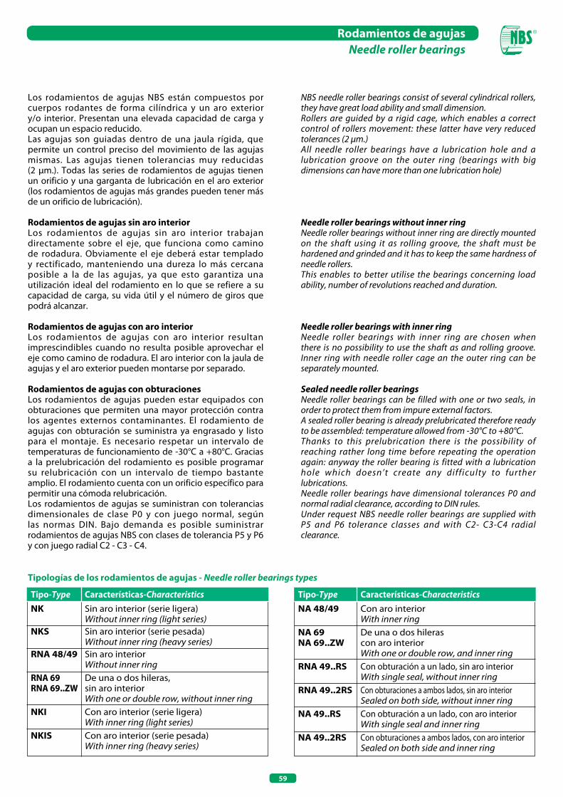
59
Los rodamientos de agujas NBS están compuestos por cuerpos rodantes de forma cilíndrica y un aro exterior y/o interior. Presentan una elevada capacidad de carga y ocupan un espacio reducido.Las agujas son guiadas dentro de una jaula rígida, que permite un control preciso del movimiento de las agujas mismas. Las agujas tienen tolerancias muy reducidas (2 µm.). Todas las series de rodamientos de agujas tienen un orificio y una garganta de lubricación en el aro exterior (los rodamientos de agujas más grandes pueden tener más de un orificio de lubricación).
Rodamientos de agujas sin aro interiorLos rodamientos de agujas sin aro interior trabajan directamente sobre el eje, que funciona como camino de rodadura. Obviamente el eje deberá estar templado y rectificado, manteniendo una dureza lo más cercana posible a la de las agujas, ya que esto garantiza una utilización ideal del rodamiento en lo que se refiere a su capacidad de carga, su vida útil y el número de giros que podrá alcanzar.
Rodamientos de agujas con aro interiorLos rodamientos de agujas con aro interior resultan imprescindibles cuando no resulta posible aprovechar el eje como camino de rodadura. El aro interior con la jaula de agujas y el aro exterior pueden montarse por separado.
Rodamientos de agujas con obturacionesLos rodamientos de agujas pueden estar equipados con obturaciones que permiten una mayor protección contra los agentes externos contaminantes. El rodamiento de agujas con obturación se suministra ya engrasado y listo para el montaje. Es necesario respetar un intervalo de temperaturas de funcionamiento de -30°C a +80°C. Gracias a la prelubricación del rodamiento es posible programar su relubricación con un intervalo de tiempo bastante amplio. El rodamiento cuenta con un orificio específico para permitir una cómoda relubricación.Los rodamientos de agujas se suministran con tolerancias dimensionales de clase P0 y con juego normal, según las normas DIN. Bajo demanda es posible suministrar rodamientos de agujas NBS con clases de tolerancia P5 y P6 y con juego radial C2 - C3 - C4.
Tipologías de los rodamientos de agujas - Needle roller bearings types
Tipo-Type Características-CharacteristicsNK Sin aro interior (serie ligera) Without inner ring (light series)NKS Sin aro interior (serie pesada) Without inner ring (heavy series)RNA 48/49 Sin aro interior Without inner ringRNA 69 De una o dos hileras,RNA 69..ZW sin aro interior With one or double row, without inner ringNKI Con aro interior (serie ligera) With inner ring (light series)NKIS Con aro interior (serie pesada) With inner ring (heavy series)
Tipo-Type Características-CharacteristicsNA 48/49 Con aro interior With inner ringNA 69 De una o dos hilerasNA 69..ZW con aro interior With one or double row, and inner ringRNA 49..RS Con obturación a un lado, sin aro interior With single seal, without inner ringRNA 49..2RS Con obturaciones a ambos lados, sin aro interior Sealed on both side, without inner ringNA 49..RS Con obturación a un lado, con aro interior With single seal and inner ringNA 49..2RS Con obturaciones a ambos lados, con aro interior Sealed on both side and inner ring
Rodamientos de agujasNeedle roller bearings
NBS needle roller bearings consist of several cylindrical rollers, they have great load ability and small dimension.Rollers are guided by a rigid cage, which enables a correct control of rollers movement: these latter have very reduced tolerances (2 µm.)All needle roller bearings have a lubrication hole and a lubrication groove on the outer ring (bearings with big dimensions can have more than one lubrication hole)
Needle roller bearings without inner ringNeedle roller bearings without inner ring are directly mounted on the shaft using it as rolling groove, the shaft must be hardened and grinded and it has to keep the same hardness of needle rollers.This enables to better utilise the bearings concerning load ability, number of revolutions reached and duration.
Needle roller bearings with inner ringNeedle roller bearings with inner ring are chosen when there is no possibility to use the shaft as and rolling groove.Inner ring with needle roller cage an the outer ring can be separately mounted.
Sealed needle roller bearings Needle roller bearings can be filled with one or two seals, in order to protect them from impure external factors.A sealed roller bearing is already prelubricated therefore ready to be assembled: temperature allowed from -30°C to +80°C.Thanks to this prelubrication there is the possibility of reaching rather long time before repeating the operation again: anyway the roller bearing is fitted with a lubrication hole which doesn’t create any difficulty to further lubrications.Needle roller bearings have dimensional tolerances P0 and normal radial clearance, according to DIN rules.Under request NBS needle roller bearings are supplied with P5 and P6 tolerance classes and with C2- C3-C4 radial clearance.

60
Rodamientos de agujas sin aro interior (serie NK • NKS • RNA 49/48 • RNA 69)Needle roller bearing without inner ring (NK • NKS • RNA 49/48 • RNA 69 series)
NK (Fw≤ 10 mm)NKS (Fw≤ 12 mm)
NK (Fw≥ 12 mm) NKS (Fw≥ 14 mm)RNA 49/48, RNA 69 (Fw≤ 35 mm)
RNA 69..ZW (Fw≥ 40 mm)
Diámetro eje (mm) Shaft
diameter (mm)
SiglaDesignation Peso (g)
Weight (g)
Coeficientes de carga (N)Basic load ratings (N)
Dinámico CDynamic C
Estático Co
Static Co
DFw C
5
7
2.9 3.7 4.7 5.7 6.9 8.2 8.3 12 11 10.3 12.8 10 13.3 15 11.8 16.8 23 20.8 25.5 27 24.4 29.1 18.5 21.8 26.6 30 20.8 23.9 16.6 28.7 30 21.5 29.8 24.9 30.5 37.9 26.1 32.2 25.7 29.3 46.8 20.5 35.4
5 10 10 5 10 12 6 12 10 6 12 12 7 14 10 7 14 12 8 15 12 8 15 16 8 16 13 9 16 12 9 16 16 10 17 12 10 17 16 10 19 13 12 19 12 12 19 16 12 22 16 14 22 16 14 22 20 14 25 16 14 22 13 14 22 22 15 23 12 15 23 16 15 23 20 15 26 16 16 24 16 16 24 20 16 24 13 16 24 22 16 28 16 17 25 16 17 25 20 18 26 16 18 26 20 18 30 16 19 27 16 19 27 20 20 28 16 20 28 20 20 32 20 20 28 13 20 28 23
2 230 1 820 35 150 2 850 2 520 35 150 2 470 2 170 31 350 3 180 2 990 31 350 2 710 2 520 29 450 3 470 3 420 29 450 3 750 3 900 27 550 4 850 5 500 27 550 4 750 4 465 27 000 4 280 4 750 26 600 5 600 6 750 26 600 4 550 5 230 25 650 5 890 7 400 25 650 5 500 5 700 24 000 6 080 6 750 23 750 8 550 10 450 23 750 9 100 9 850 22 000 9 600 10 900 22 800 12 160 14 820 23 000 13 600 13 000 21 850 8 060 9 000 23 750 8 281 11 612 18 322 8 600 10 070 21 004 10 200 12 065 21 850 12 820 16 530 21 850 13 800 13 400 21 000 10 700 13 200 20 900 13 680 17 860 20 900 8 930 10 350 22 800 15 200 20 500 20 900 14 900 15 000 20 000 11 300 14 250 17 100 14 350 19 380 20 900 11 850 15 390 19 950 15 000 20 900 19 950 16 100 17 000 18 000 12 350 16 530 19 950 15 700 22 400 19 950 12 350 16 600 19000 15 600 22 600 19 000 21 850 23 750 18 000 10 800 12 800 20 900 16 400 24 200 19 000
6
8
9
10
12
NK NKS RNA69RNA49/48
14
15
16
17
18
19
20
- - - - - - - - • NKS 8 TN - - - - • NKS 10 TN - - • NKS 12 TN - - NKS 14 - - - - - NKS 15 - - - - NKS 16 - - - - NKS 18 - - - - NKS 20 - -
- - - - - - - - - - - - - - - - - - - - - RNA 6900 - - - - - - - RNA 6901 - - - - - - - - - - - - RNA 6902
- - - - - - - - - - - - - - - - - - - - RNA 4900 - - - - - - - RNA 4901 - - - - - - - - - - - - RNA 4902 -
• NK 5/10 TN • NK 5/12 TN • NK 6/10 TN • NK 6/12 TN • NK 7/10 TN • NK 7/12 TN • NK 8/12 TN • NK 8/16 TN - NK 9/12 TN NK 9/16 TN NK 10/12 TN NK 10/16 TN - NK 12/12 NK 12/16 - NK 14/16 NK 14/20 - - - NK 15/12 NK 15/16 NK 15/20 - NK 16/16 NK 16/20 - - - NK 17/16 NK 17/20 NK 18/16 NK 18/20 - NK 19/16 NK 19/20 NK 20/16 NK 20/20 - - -
Dimensiones (mm)Dimensions (mm)
Aceite (Nº giros máx)Oil (max rpm)
Velocidad limiteLimiting Speed
• Con anillos de sellado, sin orificio y garganta de lubricación• Whit closing rings, without lubrication hole and groove
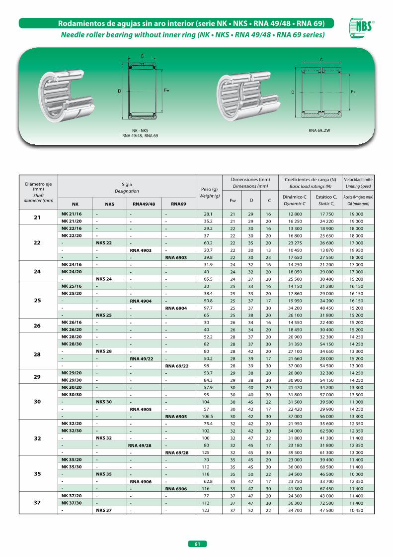
61
Rodamientos de agujas sin aro interior (serie NK • NKS • RNA 49/48 • RNA 69)Needle roller bearing without inner ring (NK • NKS • RNA 49/48 • RNA 69 series)
21 28.1
35.2
29.2
37
60.2
20.7
39.8
31.9
40
65.5
30
38.4
50.8
97.7
65
30
40
52.2
82
80
50.2
98
53.7
84.3
57.9
95
104
57
106.5
75.4
102
100
80
125
70
112
118
62.8
116
77
113
123
21 29 16
21 29 20
22 30 16
22 30 20
22 35 20
22 30 13
22 30 23
24 32 16
24 32 20
24 37 20
25 33 16
25 33 20
25 37 17
25 37 30
25 38 20
26 34 16
26 34 20
28 37 20
28 37 30
28 42 20
28 39 17
28 39 30
29 38 20
29 38 30
30 40 20
30 40 30
30 45 22
30 42 17
30 42 30
32 42 20
32 42 30
32 47 22
32 45 17
32 45 30
35 45 20
35 45 30
35 50 22
35 47 17
35 47 30
37 47 20
37 47 30
37 52 22
12 800 17 750 19 000
16 250 24 220 19 000
13 300 18 900 18 000
16 800 25 650 18 000
23 275 26 600 17 000
10 450 13 870 19 950
17 650 27 550 18 000
14 250 21 200 17 000
18 050 29 000 17 000
25 500 30 400 15 200
14 150 21 280 16 150
17 860 29 000 16 150
19 950 24 200 16 150
34 200 48 450 15 200
26 100 31 800 15 200
14 550 22 400 15 200
18 450 30 400 15 200
20 900 32 300 14 250
31 350 54 150 14 250
27 100 34 650 13 300
21 660 28 000 15 200
37 000 54 500 13 000
20 800 32 300 14 250
30 900 54 150 14 250
21 470 34 200 13 300
31 800 57 000 13 300
31 500 39 500 11 000
22 420 29 900 14 250
37 000 56 000 13 300
21 950 35 600 12 350
34 000 62 500 12 350
31 800 41 300 11 400
23 180 31 800 12 350
39 500 61 300 13 000
23 000 39 400 11 400
36 000 68 500 11 400
34 500 46 500 10 000
23 750 33 700 12 350
41 300 67 450 11 400
24 300 43 000 11 400
36 300 72 500 11 400
34 700 47 500 10 450
22
24
25
26
28
29
30
32
35
NK 21/16
NK 21/20
NK 22/16
NK 22/20
-
-
-
NK 24/16
NK 24/20
-
NK 25/16
NK 25/20
-
-
-
NK 26/16
NK 26/20
NK 28/20
NK 28/30
-
-
-
NK 29/20
NK 29/30
NK 30/20
NK 30/30
-
-
-
NK 32/20
NK 32/30
-
-
-
NK 35/20
NK 35/30
-
-
-
NK 37/20
NK 37/30
-
-
-
-
-
NKS 22
-
-
-
-
NKS 24
-
-
-
-
NKS 25
-
-
-
-
NKS 28
-
-
-
-
-
-
NKS 30
-
-
-
-
NKS 32
-
-
-
-
NKS 35
-
-
-
-
NKS 37
-
-
-
-
-
-
RNA 6903
-
-
-
-
-
-
RNA 6904
-
-
-
-
-
-
-
RNA 69/22
-
-
-
-
-
-
RNA 6905
-
-
-
-
RNA 69/28
-
-
-
-
RNA 6906
-
-
-
-
-
-
-
-
RNA 4903
-
-
-
-
-
-
RNA 4904
-
-
-
-
-
-
-
RNA 49/22
-
-
-
-
-
-
RNA 4905
-
-
-
-
RNA 49/28
-
-
-
-
RNA 4906
-
-
-
-
37
Diámetro eje (mm) Shaft
diameter (mm)
SiglaDesignation Peso (g)
Weight (g)
Dimensiones (mm)Dimensions (mm)
Coeficientes de carga (N)Basic load ratings (N)
Dinámico CDynamic C
Estático Co
Static Co
DFw CAceite (Nº giros máx)
Oil (max rpm)
Velocidad limiteLimiting Speed
NK NKS RNA69RNA49/48
NK - NKS RNA 49/48, RNA 69
RNA 69..ZW

62
Rodamientos de agujas sin aro interior (serie NK • NKS • RNA 49/48 • RNA 69)Needle roller bearing without inner ring (NK • NKS • RNA 49/48 • RNA 69 series)
38 79.4
116
78.9
120
129
89.1
147
83
125
99.3
193
84
126
139
91
139
145
94.5
142
132
255
167
236
157
182
338
167
250
221
161
296
185
258
335
241
470
221
310
356
241
338
275
488
260
370
380
38 48 20
38 48 30
40 50 20
40 50 30
40 55 22
40 52 20
40 52 36
42 52 20
42 52 30
42 55 20
42 55 36
43 53 20
43 53 30
43 58 22
45 55 20
45 55 30
45 60 22
47 57 20
47 57 30
48 62 22
48 62 40
50 62 25
50 62 35
50 65 22
52 68 22
52 68 40
55 68 25
55 68 35
55 72 22
58 72 22
58 72 40
60 72 25
60 72 35
60 80 28
63 80 25
63 80 45
65 78 25
65 78 35
65 85 28
68 82 25
68 82 35
68 85 25
68 85 45
70 85 25
70 85 35
70 90 28
40
42
43
45
47
48
50
52
55
NK 38/20 NK 38/30 NK 40/20 NK 40/30 - - - NK 42/20 NK 42/30 - - NK 43/20 NK 43/30 - NK 45/20 NK 45/30 - NK 47/20 NK 47/30 - - NK 50/25 NK 50/35 - - - NK 55/25 NK 55/35 - - - NK 60/25 NK 60/35 - - - NK 65/25 NK 65/35 - NK 68/25 NK 68/35 - -NK 70/25NK 70/35 -
- - - - NKS 40 - - - - - - - - NKS 43 - - NKS 45 - - - - - - NKS 50 - - - - NKS 55 - - - - NKS 60 - - - - NKS 65 - - - - - - NKS 70
- - - - - - RNA 69/32 - ZW - - - RNA 6907 - ZW - - - - - - - - - RNA 6908 - ZW - - - - RNA 6909 - ZW - - - - RNA 6910 - ZW - - - - RNA 6911 - ZW - - - - - - RNA 6912 - ZW - - -
- - - - - RNA 49/32 - - - RNA 4907 - - - - - - - - - RNA 4908 - - - - RNA 4909 - - - - RNA 4910 - - - - RNA 4911 - - - - - - RNA 4912 -
58
60
63
65
68
70
Diámetro eje (mm) Shaft
diameter (mm)
SiglaDesignation Peso (g)
Weight (g)
Dimensiones (mm)Dimensions (mm)
Coeficientes de carga (N)Basic load ratings (N)
Dinámico CDynamic C
Estático Co
Static Co
DFw CAceite (Nº giros máx)
Oil (max rpm)
Velocidad limiteLimiting Speed
NK NKS RNA69RNA49/48
25 000 44 500 10 450
37 000 75 000 10 450
24 700 44 650 10 450
37 000 75 000 10 450
37 200 53 500 8 500
30 000 46 800 10 500
44 650 77 900 10 450
25 200 46 550 9 500
37 500 77 900 9 500
29 900 47 500 10 450
45 600 81 700 9 500
25 700 49 000 9 500
38 500 80 750 9 500
37 000 54 150 9 000
26 100 50 350 9 500
40 000 87 000 9 500
38 500 57 000 9 000
28 000 55 000 9 000
42 500 93 500 9 000
40 850 63 650 9 000
64 000 112 000 8 120
36 100 70 300 8 550
47 500 100 700 8 550
41 800 66 500 7 000
42 750 69 350 8 100
65 500 120 650 7 600
38 000 77 900 7 600
52 500 117 000 7 600
44 000 73 000 6 000
44 650 76 000 7 600
69 400 132 000 7 200
39 900 85 500 7 100
55 000 130 000 7 100
62 500 97 500 6 000
55 100 95 000 7 100
85 500 167 200 6 650
43 500 97 000 6 650
58 200 141 300 6 650
65 800 106 700 6 100
43 000 88 000 6 100
61 000 138 000 6 100
57 000 102 600 6 600
89 300 181 450 6 200
44 000 91 000 6 100
62 000 143 000 6 100
66 500 112 000 4 500
NK - NKS RNA 49/48, RNA 69
RNA 69..ZW
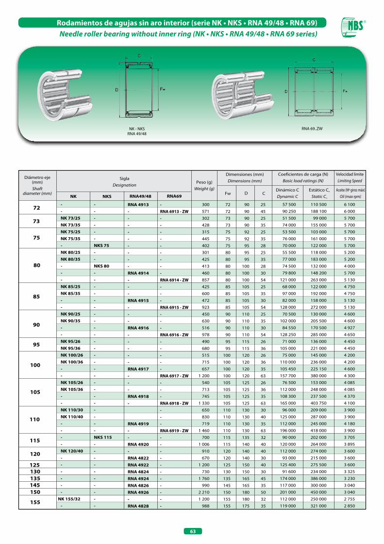
63
Rodamientos de agujas sin aro interior (serie NK • NKS • RNA 49/48 • RNA 69)Needle roller bearing without inner ring (NK • NKS • RNA 49/48 • RNA 69 series)
72 300
571
302
428
315
445
402
301
425
413
460
857
425
600
472
923
450
630
516
978
490
680
515
715
657
1 200
540
713
745
1 330
650
830
719
1 460
700
1 006
910
670
1 200
730
1 760
990
2 210
1 200
988
72 90 25
72 90 45
73 90 25
73 90 35
75 92 25
75 92 35
75 95 28
80 95 25
80 95 35
80 100 28
80 100 30
80 100 54
85 105 25
85 105 35
85 105 30
85 105 54
90 110 25
90 110 35
90 110 30
90 110 54
95 115 26
95 115 36
100 120 26
100 120 36
100 120 35
100 120 63
105 125 26
105 125 36
105 125 35
105 125 63
110 130 30
110 130 40
110 130 35
110 130 63
115 135 32
115 140 40
120 140 40
120 140 30
125 150 40
130 150 30
135 165 45
145 165 35
150 180 50
155 180 32
155 175 35
57 500 110 500 6 100
90 250 188 100 6 000
51 500 99 000 5 700
74 000 155 000 5 700
53 500 103 000 5 700
76 000 161 000 5 700
70 000 122 000 5 700
55 500 118 000 5 200
77 000 183 000 5 200
74 500 132 000 4 000
79 800 148 200 5 700
121 000 263 000 5 130
68 000 122 000 4 750
97 000 192 000 4 750
82 000 158 000 5 130
128 000 272 000 5 130
70 500 130 000 4 600
102 000 205 500 4 600
84 550 170 500 4 927
128 250 285 000 4 650
71 000 136 000 4 450
105 000 221 000 4 450
75 000 145 000 4 200
110 000 236 000 4 200
105 450 225 150 4 600
157 700 380 000 4 300
76 500 153 000 4 085
112 000 248 000 4 085
108 300 237 500 4 370
165 000 403 750 4 100
96 000 209 000 3 900
125 000 287 000 3 900
112 000 245 000 4 180
196 000 418 000 3 900
90 000 202 000 3 705
120 000 264 000 3 895
112 000 274 000 3 600
93 000 215 000 3 600
125 400 275 500 3 600
91 600 234 000 3 325
174 000 386 000 3 230
117 000 300 000 3 040
201 000 450 000 3 040
112 000 250 000 2 755
119 000 321 000 2 850
73
75
80
85
90
95
100
105
- - NK 73/25 NK 73/35 NK 75/25 NK 75/35 - NK 80/25 NK 80/35 - - - NK 85/25 NK 85/35 - - NK 90/25 NK 90/35 - - NK 95/26 NK 95/36 NK 100/26 NK 100/36 - - NK 105/26 NK 105/36 - - NK 110/30 NK 110/40 - - - - NK 120/40 - - - - - -NK 155/32 -
- - - - - - NKS 75 - - NKS 80 - - - - - - - - - - - - - - - - - - - - - - - - NKS 115 - - - - - - - - - -
- RNA 6913 - ZW - - - - - - - - - RNA 6914 - ZW - - - RNA 6915 - ZW - - - RNA 6916 - ZW - - - - - RNA 6917 - ZW - - - RNA 6918 - ZW - - - RNA 6919 - ZW - - - - - - - - - - -
RNA 4913 - - - - - - - - - RNA 4914 - - - RNA 4915 - - - RNA 4916 - - - - - RNA 4917 - - - RNA 4918 - RNA 4919 - - RNA 4920 - RNA 4822 RNA 4922 RNA 4824 RNA 4924 RNA 4826 RNA 4926 - RNA 4828
110
115
120
125 130 135 145 150
155
Diámetro eje (mm) Shaft
diameter (mm)
SiglaDesignation
Peso (g)Weight (g)
Dimensiones (mm)Dimensions (mm)
Coeficientes de carga (N)Basic load ratings (N)
Dinámico CDynamic C
Estático Co
Static Co
DFw CAceite (Nº giros máx)
Oil (max rpm)
Velocidad limiteLimiting Speed
NK NKS RNA69RNA49/48
NK - NKS RNA 49/48
RNA 69..ZW
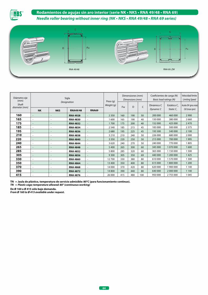
64
Rodamientos de agujas sin aro interior (serie NK • NKS • RNA 49/48 • RNA 69)Needle roller bearing without inner ring (NK • NKS • RNA 49/48 • RNA 69 series)
TN = Jaula de plástico, temperatura de servicio admisible: 80°C (para funcionamiento continuo).TN = Plastic cage; temperature allowed: 80° (continuous working)De Ø 160 a Ø 415 sólo bajo demanda.From Ø 160 to Ø 415 available under request.
160 2 350
1 600
1 700
2 540
2 680
3 210
3 350
3 620
5 400
5 800
9 300
12 700
13 400
14 000
14 800
26 000
160 190 50
165 190 40
175 200 40
185 215 45
195 225 45
210 240 50
220 250 50
240 270 50
265 300 60
285 320 60
305 350 69
330 380 80
350 400 80
370 420 80
390 440 80
415 480 100
200 000 460 000 2 900
150 000 380 000 2 660
152 000 425 000 2 470
183 000 500 000 2 375
193 500 540 000 2 100
226 000 680 000 2 000
215 000 700 000 1 995
240 000 770 000 1 805
345 000 1 070 000 1 600
365 000 1 150 000 1 500
440 000 1 200 000 1 425
610 000 1 570 000 1 300
615 000 1 800 000 1 200
620 000 1 900 000 1 140
640 000 2 000 000 1 140
950 000 2 755 000 1 045
165 175
210
240 265 285 305
-
-
-
-
-
-
-
-
-
-
-
-
-
-
-
-
-
-
-
-
-
-
-
-
-
-
-
-
-
-
-
-
RNA 4928 RNA 4830 RNA 4832 RNA 4834 RNA 4836 RNA 4838 RNA 4840 RNA 4844 RNA 4848 RNA 4852 RNA 4856 RNA 4860 RNA 4864 RNA 4868 RNA 4872 RNA 4876
-
-
-
-
-
-
-
-
-
-
-
-
-
-
-
-
185 195
220
330 350 370 390 415
Diámetro eje (mm) Shaft
diameter (mm)
SiglaDesignation Peso (g)
Weight (g)
Dimensiones (mm)Dimensions (mm)
Coeficientes de carga (N)Basic load ratings (N)
Dinámico CDynamic C
Estático Co
Static Co
DFw CAceite (Nº giros máx)
Oil (max rpm)
Velocidad limiteLimiting Speed
NK NKS RNA69RNA49/48
RNA 49/48 RNA 69..ZW

65
Rodamientos de agujas con aro interior (serie NKI • NKIS • NA 49/48 • NA 69)Needle roller bearing with inner ring (NKI • NKIS • NA 49/48 • NA 69 series)
NKI, NKIS (d≤ 7 mm) NKI (d≥ 9 mm) NKIS (d≥ 8 mm)NA 49/48 NA 69 (d≤ 30 mm)
NA 69..ZW (d≥ 32 mm)
SiglaDesignation
Peso (g)Weight (g)
Dimensiones (mm)Dimensions (mm)
Coeficientes de carga (N)Basic load ratings (N)
Dinámico CDynamic C
Estático C0
Static C0
Fd D
5
7
----∆• NKIS 6 TN--∆• NKIS 7 TNNKIS 8--∆ NKIS 9--∆ NKIS 10------NKIS 12----NKIS 15----NKIS 17----NKIS 20--------NKIS 25
11.5
15.3
13.5
17.4
19.9
13.7
18.2
34.6
46
14.6
21.9
41.4
27.3
37.1
54
21
38.4
33.3
39
25.1
44.5
58
38
45.7
32
61.6
90
41.4
53.4
32.8
68.2
98
48.5
61
70.2
141
119
50
65.4
76
130
79.4
115
76
160
160
5 8 15 12
5 8 15 16
6 9 16 12
6 9 16 16
6 10 19 13
7 10 17 12
7 10 17 16
7 12 22 16
8 14 25 16
9 12 19 12
9 12 19 16
9 15 26 16
10 14 22 16
10 14 22 20
10 16 28 16
10 14 22 13
10 14 22 22
12 16 24 16
12 16 24 20
12 16 24 13
12 16 24 22
12 18 30 16
15 19 27 16
15 19 27 20
15 20 28 13
15 20 28 23
15 22 35 20
17 21 29 16
17 21 29 20
17 22 30 13
17 22 30 23
17 24 37 20
20 24 32 16
20 24 32 20
20 25 37 17
20 25 37 30
20 28 42 20
22 26 34 16
22 26 34 20
22 28 39 17
22 28 39 30
25 29 38 20
25 29 38 30
25 30 42 17
25 30 42 30
25 32 47 22
3 750 3 900 30 400
4 900 5 700 30 400
4 270 4 750 28 500
5 600 6 750 28 500
5 510 5 700 26 000
4 500 5 200 27 500
5 900 7 400 27 500
9 100 9 800 24 000
13 680 13 110 21 500
6 200 7 002 25 000
8 500 10 500 25 000
13 800 13 500 22 000
9 808 10 500 23 500
12 150 14 800 23 500
15 000 15 100 21 000
8 006 9 000 23 700
8 281 11 612 23 700
10 800 13 100 22 800
14 000 18 400 22 800
8 900 10 300 22 800
15 200 20 500 22 800
16 000 17 000 20 000
12 350 16 530 20 900
15 650 22 400 20 900
10 050 12 900 20 900
16 400 24 200 20 900
23 500 26 600 19 000
13 000 18 200 20 000
16 500 24 900 20 000
10 450 13 850 19 900
17 650 27 550 19 900
25 000 30 000 17 000
14 250 21 150 18 050
18 000 29 500 18 050
19 950 24 200 16 200
33 000 51 000 16 000
26 500 35 500 14 000
14 500 22 400 17 000
18 700 31 000 17 000
21 650 28 000 15 200
35 600 52 250 15 200
21 000 33 000 15 200
31 500 56 000 14 000
22 400 29 900 14 250
37 000 56 000 14 250
32 000 41 300 12 500
6
8
9
Aceite (Nº giros máx)Oil (max rpm)
Velocidad limiteLimiting Speed
NKI NKIS NA 69B
10
12
20
22
25
----------------NA 6900---NA 6901----NA 6902----NA 6903----NA6904----NA 69/22---NA 6905-
NA 49/48
---------------NA 4900---NA 4901----NA 4902----NA 4903----NA 4904----NA 49/22---NA 4905--
15
17
Diámetro eje (mm) Shaft
diameter (mm)
• NKI 5/12 TN •
NKI 5/16 TN• NKI 6/12 TN• NKI 6/16 TN -• NKI 7/12 TN• NKI 7/16 TN - - NKI 9/12 NKI 9/16 - NKI 10/16 NKI 10/20 - - - NKI 12/16 NKI 12/20 - - - NKI 15/16 NKI 15/20 - - - NKI 17/16 NKI 17/20 - - - NKI 20/16 NKI 20/20 - - - NKI 22/16 NKI 22/20 - - NKI 25/20 NKI 25/30 - - -

66
Rodamientos de agujas con aro interior (serie NKI • NKIS • NA 49/48 • NA 69)Needle roller bearing with inner ring (NKI • NKIS • NA 49/48 • NA 69 series)
42
50
NKI 28/20
NKI 28/30
-
-
NKI 30/20
NKI 30/30
-
-
-
NKI 32/20
NKI 32/30
-
-
NKI 35/20
NKI 35/30
-
-
-
NKI 38/20
NKI 38/30
NKI 40/20
NKI 40/30
-
-
-
NKI 42/20
NKI 42/30
NKI 45/25
NKI 45/35
-
-
-
NKI 50/25
NKI 50/35
-
-
-
NKI 55/25
NKI 55/35
-
-
-
-
-
-
-
-
-
-
-
NKIS 30
-
-
-
-
-
-
-
-
NKIS 35
-
-
-
-
-
-
NKIS 40
-
-
-
-
-
-
NKIS 45
-
-
-
-
NKIS 50
-
-
-
-
NKIS 55
96.5
146
90.7
170
112
170
101
192
184
101
180
150
272
127
193
151
301
210
136
207
142
216
230
430
281
138
222
218
322
260
479
336
262
379
264
515
510
272
357
386
760
558
28 32 42 20
28 32 42 30
28 32 45 17
28 32 45 30
30 35 45 20
30 35 45 30
30 35 47 17
30 35 47 30
30 37 52 22
32 37 47 20
32 37 47 30
32 40 52 20
32 40 52 36
35 40 50 20
35 40 50 30
35 42 55 20
35 42 55 36
35 43 58 22
38 43 53 20
38 43 53 30
40 45 55 20
40 45 55 30
40 48 62 22
40 48 62 40
40 50 65 22
42 47 57 20
42 47 57 30
45 50 62 25
45 50 62 35
45 52 68 22
45 52 68 40
45 55 72 22
50 55 68 25
50 55 68 35
50 58 72 22
50 58 72 40
50 60 80 28
55 60 72 25
55 60 72 35
55 63 80 25
55 63 80 45
55 65 85 28
22 700 36 500 13 300
34 000 61 000 13 300
23 200 31 800 12 350
38 400 59 800 12 350
23 500 41 000 12 350
36 000 68 000 12 350
23 000 34 000 12 350
42 500 70 500 12 350
35 000 48 000 12 350
23 650 41 300 11 400
36 500 71 500 11 400
28 950 45 100 11 400
44 650 77 900 11 400
25 000 45 000 11 400
37 000 75 000 11 400
29 900 47 500 10 450
45 600 81 700 10 450
37 000 56 000 10 450
25 000 49 000 10 450
40 000 84 000 10 450
26 100 50 350 9 500
35 000 86 000 9 500
40 850 63 650 9 000
64 000 112 000 9 000
41 000 65 000 9 000
26 000 52 500 9 500
41 000 92 000 9 500
36 000 70 000 8 550
47 500 100 700 8 550
42 750 69 350 8 075
65 550 120 650 8 075
43 000 71 000 8 075
38 000 78 000 8 075
52 500 117 000 8 075
44 650 76 000 7 600
69 350 132 000 7 600
60 000 95 000 7 200
41 000 88 000 7 100
48 000 126 000 7 100
55 100 95 000 7 100
82 560 172 000 7 156
65 500 107 000 7 100
45
55
-
-
-
NA 69/28
-
-
-
NA 6906
-
-
-
-
NA 69/32 - ZW
-
-
-
NA 6907 - ZW
-
-
-
-
-
-
NA 6908 - ZW
-
-
-
-
-
-
NA 6909 - ZW
-
-
-
-
NA 6910 - ZW
-
-
-
-
NA 6911 - ZW
-
-
-
NA 49/28
-
-
-
NA 4906
-
-
-
-
NA 49/32
-
-
-
NA 4907
-
-
-
-
-
-
NA 4908
-
-
-
-
-
-
NA 4909
-
-
-
-
NA 4910
-
-
-
-
NA 4911
-
-
28
30
32
35
38
40
Diámetro eje (mm) Shaft
diameter (mm)
SiglaDesignation
Peso (g)Weight (g)
Dimensiones (mm)Dimensions (mm)
Coeficientes de carga (N)Basic load ratings (N)
Dinámico CDynamic C
Estático C0
Static C0
Fd DAceite (Nº giros máx)
Oil (max rpm)
Velocidad limiteLimiting Speed
NKI NKIS NA 69B
NA 49/48
NKI, NKISNA 49/48, NA 69 NA 69..ZW (d≥ 32 mm)
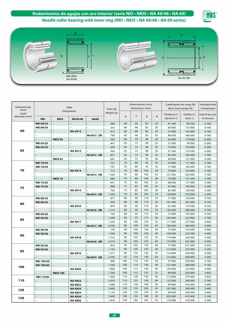
67
Rodamientos de agujas con aro interior (serie NKI • NKIS • NA 49/48 • NA 69)Needle roller bearing with inner ring (NKI • NKIS • NA 49/48 • NA 69 series)
60
65
70
75
NKI 60/25NKI 60/35---NKI 65/25NKI 65/35- --NKI 70/25NKI 70/35---NKI 75/25NKI 75/35--NKI 80/25NKI 80/35--NKI 85/26NKI 85/36--NKI 90/26NKI 90/36--NKI 95/26NKI 95/36--NKI 100/30NKI 100/40--∆NKI 110/40------
80
85
90
95
100
110
120
130
----NKIS 60----NKIS 65 ----NKIS 70-----------------------NKIS 100-------
--NA 4912----NA 4913----NA 4914----NA 4915---NA 4916---NA 4917---NA 4918---NA 4919---NA 4920--NA 4922NA 4822NA 4924NA 4824NA 4926NA 4826
---NA 6912 - ZW----NA 6913 - ZW----NA 6914 - ZW----NA 6915 - ZW---NA 6916 - ZW---NA 6917 - ZW---NA 6918 - ZW---NA 6919 - ZW-----------
388
553
412
798
550
467
659
456
821
641
521
737
712
1 326
680
641
908
765
1 429
677
959
870
1 510
743
1 040
1 250
2 200
778
1 090
1 312
2 310
816
1 145
1 371
2 500
990
1 330
1 900
1 340
1 460
2 070
1 080
2 860
1 170
3 900
1 810
60 68 82 25
60 68 82 35
60 68 85 25
60 68 85 45
60 70 90 28
65 73 90 25
65 73 90 35
65 72 90 25
65 72 90 45
65 75 95 28
70 80 95 25
70 80 95 35
70 80 100 30
70 80 100 54
70 80 100 28
75 85 105 25
75 85 105 35
75 85 105 30
75 85 105 54
80 90 110 25
80 90 110 35
80 90 110 30
80 90 110 54
85 95 115 26
85 95 115 36
85 100 120 35
85 100 120 63
90 100 120 26
90 100 120 36
90 105 125 35
90 105 125 63
95 105 125 26
95 105 125 36
95 110 130 35
95 110 130 63
100 110 130 30
100 110 130 40
100 115 140 40
100 115 135 32
110 120 140 40
110 125 150 40
110 120 140 30
120 135 165 45
120 130 150 30
130 150 180 50
130 145 165 35
41 300 84 550 6 700
60 000 137 000 6 700
57 000 102 600 6 700
88 500 186 000 6 700
65 000 110 000 6 200
51 000 99 000 6 200
73 000 154 000 6 200
57 500 110 500 6 200
87 600 194 500 5 700
69 000 121 000 6 200
55 000 117 000 5 700
77 000 182 000 5 700
79 000 154 000 5 700
121 000 263 000 5 700
73 000 131 500 5 700
68 000 121 000 5 200
97 000 192 000 5 200
82 000 158 000 5 200
128 000 272 000 5 200
71 000 130 000 4 750
101 000 207 000 4 750
81 000 170 500 4 750
130 500 280 600 4 750
71 000 135 000 4 700
105 000 222 000 4 700
111 000 237 000 4 600
166 000 400 000 4 600
75 000 145 000 4 400
109 000 235 500 4 400
114 000 250 000 4 300
172 000 425 000 4 300
77 000 153 000 4 250
112 000 235 000 4 250
116 000 260 000 4 200
174 000 440 000 4 200
97 000 200 000 4 100
127 000 280 000 4 100
120 000 274 000 4 000
90 000 203 000 3 850
112 000 274 000 3 850
132 000 290 000 3 700
94 000 216 000 3 900
181 000 390 000 3 400
99 000 239 000 3 600
203 000 470 000 3 100
118 000 310 000 3 200
Diámetro eje (mm) Shaft
diameter (mm)
SiglaDesignation
Peso (g)Weight (g)
Dimensiones (mm)Dimensions (mm)
Coeficientes de carga (N)Basic load ratings (N)
Dinámico CDynamic C
Estático C0
Static C0
Fd DAceite (Nº giros máx)
Oil (max rpm)
Velocidad limiteLimiting Speed
NKI NKIS NA69B
NA49/48
NKI, NKISNA 49/48 NA 69..ZW
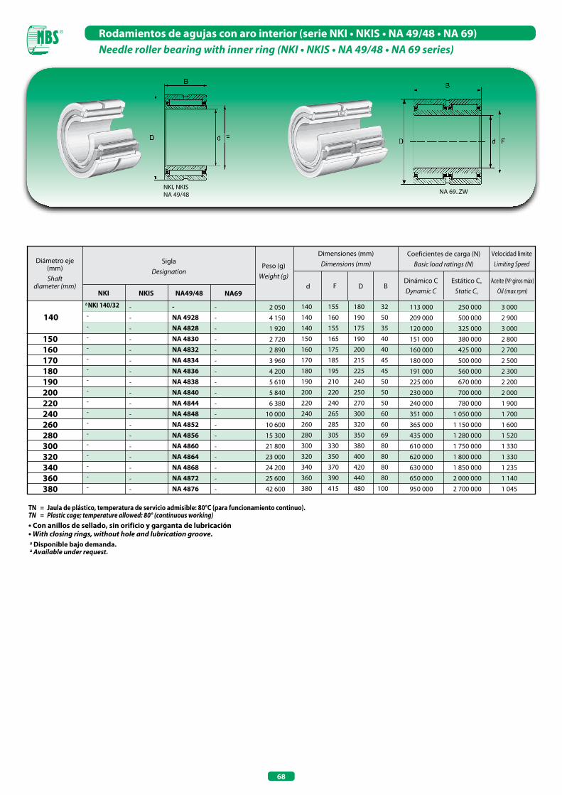
68
Rodamientos de agujas con aro interior (serie NKI • NKIS • NA 49/48 • NA 69)Needle roller bearing with inner ring (NKI • NKIS • NA 49/48 • NA 69 series)
TN = Jaula de plástico, temperatura de servicio admisible: 80°C (para funcionamiento continuo). TN = Plastic cage; temperature allowed: 80° (continuous working)• Con anillos de sellado, sin orificio y garganta de lubricación • With closing rings, without hole and lubrication groove.∆ Disponible bajo demanda. ∆ Available under request.
140
∆ NKI 140/32-
-
-
-
-
-
-
-
-
-
-
-
-
-
-
-
-
-
-
-
-
-
-
-
-
-
-
-
-
-
-
-
-
-
-
-NA 4928NA 4828NA 4830NA 4832NA 4834NA 4836NA 4838NA 4840NA 4844NA 4848NA 4852NA 4856NA 4860NA 4864NA 4868NA 4872NA 4876
-
-
-
-
-
-
-
-
-
-
-
-
-
-
-
-
-
-
2 050
4 150
1 920
2 720
2 890
3 960
4 200
5 610
5 840
6 380
10 000
10 600
15 300
21 800
23 000
24 200
25 600
42 600
140 155 180 32
140 160 190 50
140 155 175 35
150 165 190 40
160 175 200 40
170 185 215 45
180 195 225 45
190 210 240 50
200 220 250 50
220 240 270 50
240 265 300 60
260 285 320 60
280 305 350 69
300 330 380 80
320 350 400 80
340 370 420 80
360 390 440 80
380 415 480 100
113 000 250 000 3 000
209 000 500 000 2 900
120 000 325 000 3 000
151 000 380 000 2 800
160 000 425 000 2 700
180 000 500 000 2 500
191 000 560 000 2 300
225 000 670 000 2 200
230 000 700 000 2 000
240 000 780 000 1 900
351 000 1 050 000 1 700
365 000 1 150 000 1 600
435 000 1 280 000 1 520
610 000 1 750 000 1 330
620 000 1 800 000 1 330
630 000 1 850 000 1 235
650 000 2 000 000 1 140
950 000 2 700 000 1 045
150 160 170 180 190 200 220 240 260 280 300 320 340 360 380
Diámetro eje (mm) Shaft
diameter (mm)
SiglaDesignation
Peso (g)Weight (g)
Dimensiones (mm)Dimensions (mm)
Coeficientes de carga (N)Basic load ratings (N)
Dinámico CDynamic C
Estático C0
Static C0
Fd DAceite (Nº giros máx)
Oil (max rpm)
Velocidad limiteLimiting Speed
NKI NKIS NA69B
NA49/48
NKI, NKISNA 49/48 NA 69..ZW
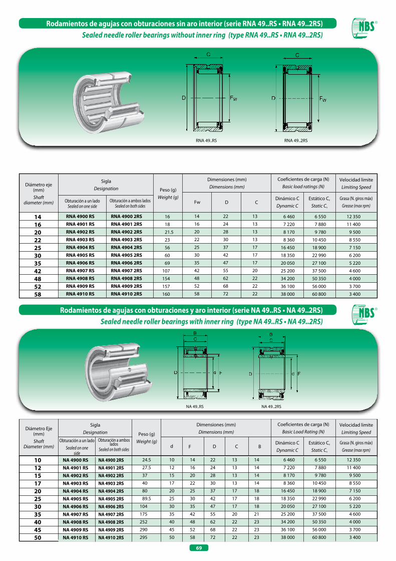
69
Rodamientos de agujas con obturaciones sin aro interior (serie RNA 49..RS • RNA 49..2RS)Sealed needle roller bearings without inner ring (type RNA 49..RS • RNA 49..2RS)
Rodamientos de agujas con obturaciones y aro interior (serie NA 49..RS • NA 49..2RS)Sealed needle roller bearings with inner ring (type NA 49..RS • NA 49..2RS)
RNA 49..RS RNA 49..2RS
14 16 20 22 25 30 35 42 48 52 58
Diámetro eje (mm) Shaft
diameter (mm)
SiglaDesignation Peso (g)
Weight (g)
Dimensiones (mm)Dimensions (mm)
Coeficientes de carga (N)Basic load ratings (N)
Dinámico CDynamic C
Estático C0
Static C0
Fw D
RNA 4900 RS RNA 4900 2RS
RNA 4901 RS RNA 4901 2RS
RNA 4902 RS RNA 4902 2RS
RNA 4903 RS RNA 4903 2RS
RNA 4904 RS RNA 4904 2RS
RNA 4905 RS RNA 4905 2RS
RNA 4906 RS RNA 4906 2RS
RNA 4907 RS RNA 4907 2RS
RNA 4908 RS RNA 4908 2RS
RNA 4909 RS RNA 4909 2RS
RNA 4910 RS RNA 4910 2RS
16
18
21.5
23
56
60
69
107
154
157
160
14 22 13
16 24 13
20 28 13
22 30 13
25 37 17
30 42 17
35 47 17
42 55 20
48 62 22
52 68 22
58 72 22
6 460 6 550 12 350
7 220 7 880 11 400
8 170 9 780 9 500
8 360 10 450 8 550
16 450 18 900 7 150
18 350 22 990 6 200
20 050 27 100 5 220
25 200 37 500 4 600
34 200 50 350 4 000
36 100 56 000 3 700
38 000 60 800 3 400
C
Velocidad limiteLimiting Speed
Grasa (N. giros máx)Grease (max rpm)
Obturación a un ladoSealed on one side
Obturación a ambos ladosSealed on both sides
SiglaDesignation Peso (g)
Weight (g)
Dimensiones (mm)Dimensions (mm)
Coeficientes de carga (N)Basic Load Rating (N)
Dinámico CDynamic C
Estático C0
Static C0
d F D C
Velocidad limiteLimiting Speed
Grasa (N. giros máx)Grease (max rpm)
BObturación a un lado
Sealed on one side
Obturación a ambos lados
Sealed on both sides
Diámetro Eje (mm) Shaft
Diameter (mm)
10 12 15 17 20 25 30 35 40 45 50
NA 4900 RS NA 4900 2RS
NA 4901 RS NA 4901 2RS
NA 4902 RS NA 4902 2RS
NA 4903 RS NA 4903 2RS
NA 4904 RS NA 4904 2RS
NA 4905 RS NA 4905 2RS
NA 4906 RS NA 4906 2RS
NA 4907 RS NA 4907 2RS
NA 4908 RS NA 4908 2RS
NA 4909 RS NA 4909 2RS
NA 4910 RS NA 4910 2RS
24.5
27.5
37
40
80
89.5
104
175
252
290
295
10 14 22 13 14
12 16 24 13 14
15 20 28 13 14
17 22 30 13 14
20 25 37 17 18
25 30 42 17 18
30 35 47 17 18
35 42 55 20 21
40 48 62 22 23
45 52 68 22 23
50 58 72 22 23
6 460 6 550 12 350
7 220 7 880 11 400
8 170 9 780 9 500
8 360 10 450 8 550
16 450 18 900 7 150
18 350 22 990 6 200
20 050 27 100 5 220
25 200 37 500 4 600
34 200 50 350 4 000
36 100 56 000 3 700
38 000 60 800 3 400
NA 49..RS NA 49..2RS


RODAMIENTOS DE AGUJAS SIN BORDESNEEDLE ROLLER BEARINGS WITHOUT RIBS

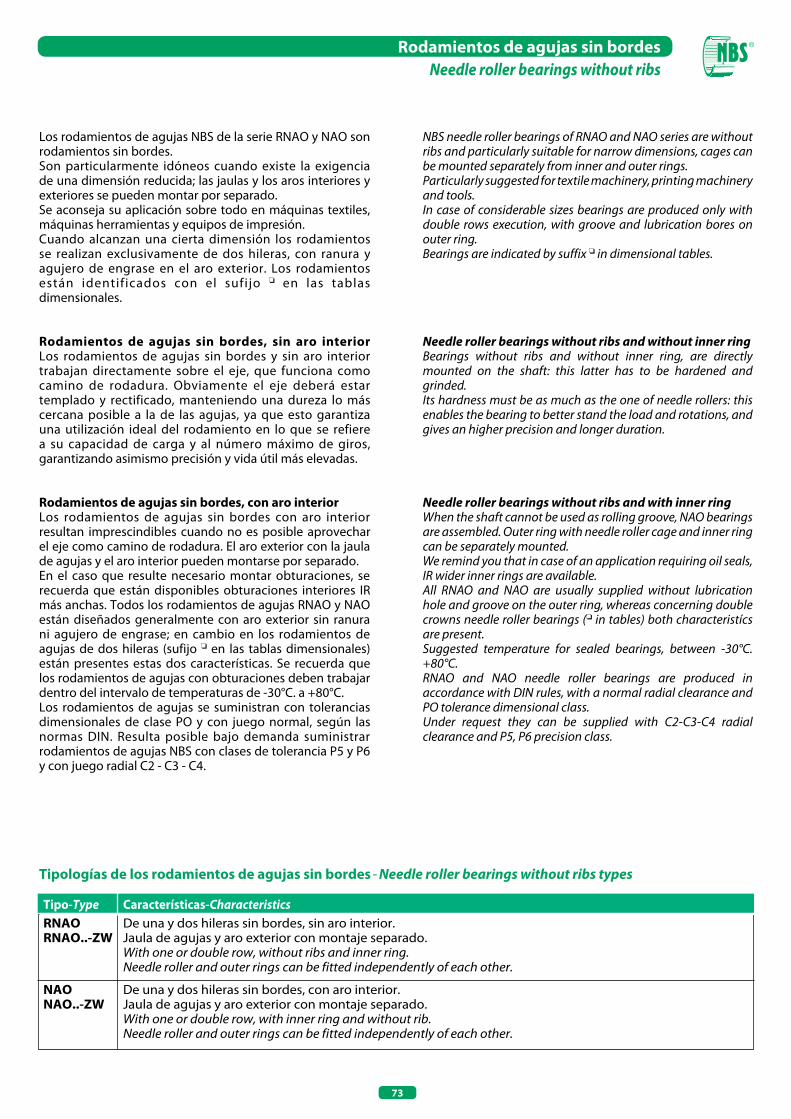
73
Rodamientos de agujas sin bordesNeedle roller bearings without ribs
Los rodamientos de agujas NBS de la serie RNAO y NAO son rodamientos sin bordes.Son particularmente idóneos cuando existe la exigencia de una dimensión reducida; las jaulas y los aros interiores y exteriores se pueden montar por separado.Se aconseja su aplicación sobre todo en máquinas textiles, máquinas herramientas y equipos de impresión. Cuando alcanzan una cierta dimensión los rodamientos se realizan exclusivamente de dos hileras, con ranura y agujero de engrase en el aro exterior. Los rodamientos están identificados con el sufijo o en las tablas dimensionales.
Rodamientos de agujas sin bordes, sin aro interior Los rodamientos de agujas sin bordes y sin aro interior trabajan directamente sobre el eje, que funciona como camino de rodadura. Obviamente el eje deberá estar templado y rectificado, manteniendo una dureza lo más cercana posible a la de las agujas, ya que esto garantiza una utilización ideal del rodamiento en lo que se refiere a su capacidad de carga y al número máximo de giros, garantizando asimismo precisión y vida útil más elevadas.
Rodamientos de agujas sin bordes, con aro interior Los rodamientos de agujas sin bordes con aro interior resultan imprescindibles cuando no es posible aprovechar el eje como camino de rodadura. El aro exterior con la jaula de agujas y el aro interior pueden montarse por separado.En el caso que resulte necesario montar obturaciones, se recuerda que están disponibles obturaciones interiores IR más anchas. Todos los rodamientos de agujas RNAO y NAO están diseñados generalmente con aro exterior sin ranura ni agujero de engrase; en cambio en los rodamientos de agujas de dos hileras (sufijo o en las tablas dimensionales) están presentes estas dos características. Se recuerda que los rodamientos de agujas con obturaciones deben trabajar dentro del intervalo de temperaturas de -30°C. a +80°C.Los rodamientos de agujas se suministran con tolerancias dimensionales de clase PO y con juego normal, según las normas DIN. Resulta posible bajo demanda suministrar rodamientos de agujas NBS con clases de tolerancia P5 y P6 y con juego radial C2 - C3 - C4.
Tipologías de los rodamientos de agujas sin bordes - Needle roller bearings without ribs types
Tipo-Type Características-CharacteristicsRNAO De una y dos hileras sin bordes, sin aro interior.RNAO..-ZW Jaula de agujas y aro exterior con montaje separado. With one or double row, without ribs and inner ring. Needle roller and outer rings can be fitted independently of each other.
NAO De una y dos hileras sin bordes, con aro interior.NAO..-ZW Jaula de agujas y aro exterior con montaje separado. With one or double row, with inner ring and without rib. Needle roller and outer rings can be fitted independently of each other.
NBS needle roller bearings of RNAO and NAO series are without ribs and particularly suitable for narrow dimensions, cages can be mounted separately from inner and outer rings.Particularly suggested for textile machinery, printing machinery and tools.In case of considerable sizes bearings are produced only with double rows execution, with groove and lubrication bores on outer ring.Bearings are indicated by suffix o in dimensional tables.
Needle roller bearings without ribs and without inner ringBearings without ribs and without inner ring, are directly mounted on the shaft: this latter has to be hardened and grinded.Its hardness must be as much as the one of needle rollers: this enables the bearing to better stand the load and rotations, and gives an higher precision and longer duration.
Needle roller bearings without ribs and with inner ringWhen the shaft cannot be used as rolling groove, NAO bearings are assembled. Outer ring with needle roller cage and inner ring can be separately mounted.We remind you that in case of an application requiring oil seals, IR wider inner rings are available.All RNAO and NAO are usually supplied without lubrication hole and groove on the outer ring, whereas concerning double crowns needle roller bearings (o in tables) both characteristícs are present.Suggested temperature for sealed bearings, between -30°C. +80°C.RNAO and NAO needle roller bearings are produced in accordance with DIN rules, with a normal radial clearance and PO tolerance dimensional class.Under request they can be supplied with C2-C3-C4 radial clearance and P5, P6 precision class.
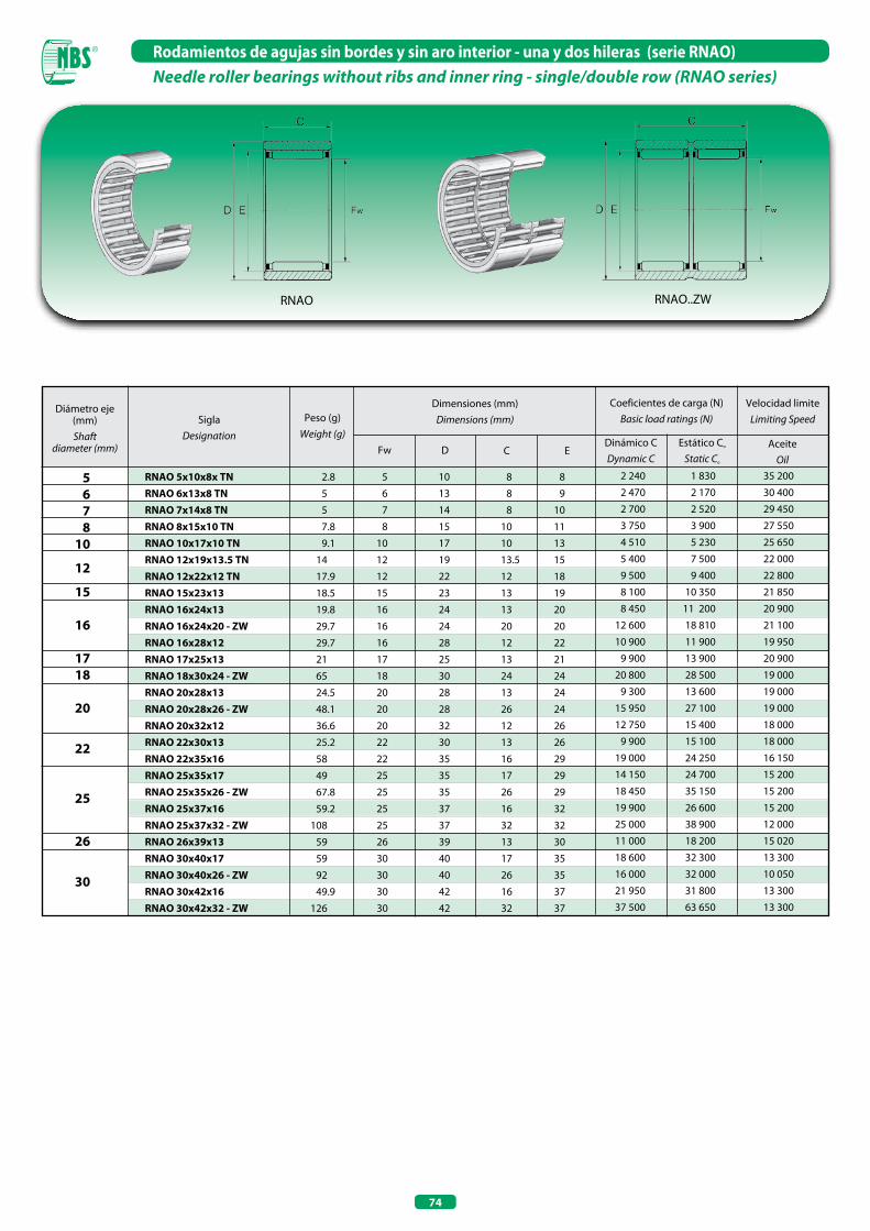
74
Rodamientos de agujas sin bordes y sin aro interior - una y dos hileras (serie RNAO)Needle roller bearings without ribs and inner ring - single/double row (RNAo series)
Diámetro eje (mm) Shaft
diameter (mm)
SiglaDesignation
Peso (g)Weight (g)
Dimensiones (mm)Dimensions (mm)
Coeficientes de carga (N)Basic load ratings (N)
Dinámico CDynamic C
Estático Co
Static Co
Fw D C
5 6 7 8 10 12
15 16
17 18 20
22
25
26
30
RNAO 5x10x8x TN RNAO 6x13x8 TN RNAO 7x14x8 TN RNAO 8x15x10 TN RNAO 10x17x10 TN RNAO 12x19x13.5 TN RNAO 12x22x12 TN RNAO 15x23x13 RNAO 16x24x13 RNAO 16x24x20 - ZW RNAO 16x28x12 RNAO 17x25x13 RNAO 18x30x24 - ZW RNAO 20x28x13 RNAO 20x28x26 - ZW RNAO 20x32x12 RNAO 22x30x13 RNAO 22x35x16 RNAO 25x35x17 RNAO 25x35x26 - ZW RNAO 25x37x16 RNAO 25x37x32 - ZW RNAO 26x39x13 RNAO 30x40x17 RNAO 30x40x26 - ZW RNAO 30x42x16 RNAO 30x42x32 - ZW
2.8
5
5
7.8
9.1
14
17.9
18.5
19.8
29.7
29.7
21
65
24.5
48.1
36.6
25.2
58
49
67.8
59.2
108
59
59
92
49.9
126
5 10 8 8
6 13 8 9
7 14 8 10
8 15 10 11
10 17 10 13
12 19 13.5 15
12 22 12 18
15 23 13 19
16 24 13 20
16 24 20 20
16 28 12 22
17 25 13 21
18 30 24 24
20 28 13 24
20 28 26 24
20 32 12 26
22 30 13 26
22 35 16 29
25 35 17 29
25 35 26 29
25 37 16 32
25 37 32 32
26 39 13 30
30 40 17 35
30 40 26 35
30 42 16 37
30 42 32 37
2 240 1 830 35 200
2 470 2 170 30 400
2 700 2 520 29 450
3 750 3 900 27 550
4 510 5 230 25 650
5 400 7 500 22 000
9 500 9 400 22 800
8 100 10 350 21 850
8 450 11 200 20 900
12 600 18 810 21 100
10 900 11 900 19 950
9 900 13 900 20 900
20 800 28 500 19 000
9 300 13 600 19 000
15 950 27 100 19 000
12 750 15 400 18 000
9 900 15 100 18 000
19 000 24 250 16 150
14 150 24 700 15 200
18 450 35 150 15 200
19 900 26 600 15 200
25 000 38 900 12 000
11 000 18 200 15 020
18 600 32 300 13 300
16 000 32 000 10 050
21 950 31 800 13 300
37 500 63 650 13 300
E
Velocidad limiteLimiting Speed
AceiteOil
RNAO RNAO..ZW

75
Rodamientos de agujas sin bordes y sin aro interior - una y dos hileras (serie RNAO)Needle roller bearings without ribs and inner ring - single/double row (RNAo series)
TN = Jaula de plástico, temperatura de servicio admisible: 80°C (funcionamiento continuo).TN = Plastic cage; temperature allowed: 80°C (continuous working).ZW = De dos hileras , con garganta y orificio de lubricación.ZW = Double row, with groove and lubrication hole.
35
37
40 42 45
50 55 60
65 70 80 85 90
100
RNAO 35x45x13 RNAO 35x45x17 RNAO 35x45x26 - ZW RNAO 35x47x16 RNAO 35x47x18 RNAO 35x47x32 - ZW RNAO 37x52x18 RNAO 40x50x17 RNAO 40x50x34 - ZW RNAO 40x55x20 RNAO 40x55x40 - ZW RNAO 42x57x20 RNAO 45x55x17 RNAO 45x62x40 - ZW RNAO 50x62x20 RNAO 50x65x20 RNAO 50x65x40 - ZW RNAO 55x68x20 RNAO 60x78x20 RNAO 60x78x40 - ZW RNAO 65x85x30 RNAO 70x90x30 RNAO 80x100x30 RNAO 85x105x25 RNAO 90x105x26 RNAO 90x110x30 RNAO 100x120x30
50
60
88
75
86
149
115
72
151
144
268
132
82.5
368
140
162
321
157
253
435
464
488
527
449
373
600
671
35 45 13 40
35 45 17 40
35 45 26 40
35 47 16 42
35 47 18 42
35 47 32 42
37 52 18 44
40 50 17 45
40 50 34 45
40 55 20 47
40 55 40 48
42 57 20 50
45 55 17 50
45 62 40 53
50 62 20 55
50 65 20 58
50 65 40 58
55 68 20 60
60 78 20 68
60 78 40 68
65 85 30 73
70 90 30 78
80 100 30 88
85 105 25 93
90 105 26 98
90 110 30 98
100 120 30 108
15 400 26 600 11 400
19 750 36 600 11 400
26 100 53 200 11 400
23 180 35 600 11 400
26 100 40 850 11 400
39 900 71 250 11 400
18 900 35 500 8 800
20 350 39 400 10 450
34 700 78 850 10 450
30 900 54 150 10 450
58 900 112 100 9 500
34 200 56 000 10 000
21 400 43 700 9 500
63 650 128 250 8 600
25 200 57 000 8 600
33 700 58 900 8 100
57 950 117 800 8 100
27 100 62 700 7 600
41 300 80 750 6 700
71 250 162 450 6 700
54 150 116 850 6 200
57 000 128 250 5 700
67 450 167 200 5 300
54 150 129 200 4 900
57 950 142 500 4 750
64 600 163 400 4 700
67 450 178 600 4 300
Diámetro eje (mm) Shaft
diameter (mm)
SiglaDesignation
Peso (g)Weight (g)
Dimensiones (mm)Dimensions (mm)
Coeficientes de carga (N)Basic load ratings (N)
Dinámico CDynamic C
Estático Co
Static Co
Fw D C E
Velocidad limiteLimiting Speed
AceiteOil
RNAO RNAO..ZW
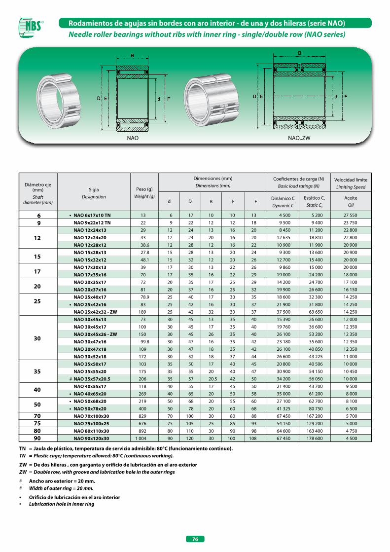
76
Rodamientos de agujas sin bordes con aro interior - de una y dos hileras (serie NAO)Needle roller bearings without ribs with inner ring - single/double row (NAo series)
TN = Jaula de plástico, temperatura de servicio admisible: 80°C (funcionamiento continuo).TN = Plastic cage; temperature allowed: 80°C (continuous working).
ZW = De dos hileras , con garganta y orificio de lubricación en el aro exteriorZW = Double row, with groove and lubrication hole in the outer rings
# Ancho aro exterior = 20 mm. # Width of outer ring = 20 mm.
• Orificio de lubricación en el aro interior• Lubrication hole in inner ring
6 9 12 15 17
20 25
30
35
40
50
70 75 80 90
Diámetro eje (mm) Shaft
diameter (mm)
SiglaDesignation
Peso (g)Weight (g)
Dimensiones (mm)Dimensions (mm)
Coeficientes de carga (N)Basic load ratings (N)
Dinámico CDynamic C
Estático Co
Static Co
d D B
• NAO 6x17x10 TN NAO 9x22x12 TN NAO 12x24x13 NAO 12x24x20 NAO 12x28x12 NAO 15x28x13 NAO 15x32x12 NAO 17x30x13 NAO 17x35x16 NAO 20x35x17 NAO 20x37x16 NAO 25x40x17 • NAO 25x42x16 NAO 25x42x32 - ZW NAO 30x45x13 NAO 30x45x17 NAO 30x45x26 - ZW NAO 30x47x16 NAO 30x47x18 NAO 30x52x18 NAO 35x50x17 NAO 35x55x20 # NAO 35x57x20.5 NAO 40x55x17 • NAO 40x65x20 • NAO 50x68x20 • NAO 50x78x20 NAO 70x100x30 NAO 75x100x25 NAO 80x110x30 NAO 90x120x30
13
22
29
43
38.6
27.8
48.1
39
70
72
81
78.9
83
189
73
100
150
99.8
109
172
103
175
206
118
269
219
400
829
676
892
1 004
6 17 10 10 13
9 22 12 12 18
12 24 13 16 20
12 24 20 16 20
12 28 12 16 22
15 28 13 20 24
15 32 12 20 26
17 30 13 22 26
17 35 16 22 29
20 35 17 25 29
20 37 16 25 32
25 40 17 30 35
25 42 16 30 37
25 42 32 30 37
30 45 13 35 40
30 45 17 35 40
30 45 26 35 40
30 47 16 35 42
30 47 18 35 42
30 52 18 37 44
35 50 17 40 45
35 55 20 40 47
35 57 20.5 42 50
40 55 17 45 50
40 65 20 50 58
50 68 20 55 60
50 78 20 60 68
70 100 30 80 88
75 105 25 85 93
80 110 30 90 98
90 120 30 100 108
4 500 5 200 27 550
9 500 9 400 23 750
8 450 11 200 22 800
12 635 18 810 22 800
10 900 11 900 20 900
9 300 13 600 20 900
12 700 15 400 20 000
9 860 15 000 20 000
19 000 24 200 18 000
14 200 24 700 17 100
19 900 26 600 16 150
18 600 32 300 14 250
21 900 31 800 14 250
37 500 63 650 14 250
15 390 26 600 12 000
19 760 36 600 12 350
26 100 53 200 12 350
23 180 35 600 12 350
26 100 40 850 12 350
26 600 43 225 11 000
20 800 40 506 10 000
30 900 54 150 10 450
34 200 56 050 10 000
21 400 43 700 9 500
35 000 61 200 8 000
27 100 62 700 8 100
41 325 80 750 6 500
67 450 167 200 5 700
54 150 129 200 5 000
64 600 163 400 4 750
67 450 178 600 4 500
F
Velocidad limiteLimiting Speed
AceiteOil
E
NAO..ZWNAO

RODAMIENTOS DE AGUJAS AUTOALINEABLESALIGNING NEEDLE ROLLER BEARINGS

79
Rodamientos de agujas autoalineablesAligning needle roller bearings
La principal característica de los rodamientos de agujas autoalineables es la posibilidad de alineación del aro exte-rior, gracias a una serie de aros de apoyo de plástico inser-tados entre el aro exterior y el casquillo. Esta característica permite además la absorción de eventuales desalineaciones del eje, hasta un máximo de 2°/3°. La jaula de agujas, el aro exterior y el casquillo exterior constituyen un único grupo de montaje. Es importante recordar que los rodamientos de agujas autoalineables cuentan con anillos de apoyo de plástico y que deben siempre trabajar dentro del intervalo de temperaturas de -30°C. a +80°C. Los rodamientos de agujas autoalineables se deberán montar con interferencia en el orificio de alojamiento. La posibilidad de alineación está garantizada por el acoplamiento del casquillo y del aro exterior.
RPNA De agujas autoalineables sin aro interior Aligning without inner ring
PNA De agujas autoalineables con aro interior Aligning with inner ring
Tipo-Type Características-Characteristics
Aligning heavy duty needle roller bearings have an orientable outer ring, this is possible thanks to a series of plastic support rings inserted between the outer ring and the drawn cup.This characteristic enables the absorption of possible shaft misalignment up to 2°/3°. Needle roller cage, outer ring and drawn cup create a sole mounting group. Important is to remember that with heavy duty needle roller bearings, plastic support rings are assembled, therefore temperature has to be within -30°C and +80°C.Aligning heavy duty needle bearings are assembled with interference inside the housing bore, furthermore their orientability is guaranteed by the coupling of drawn cup and outer ring.
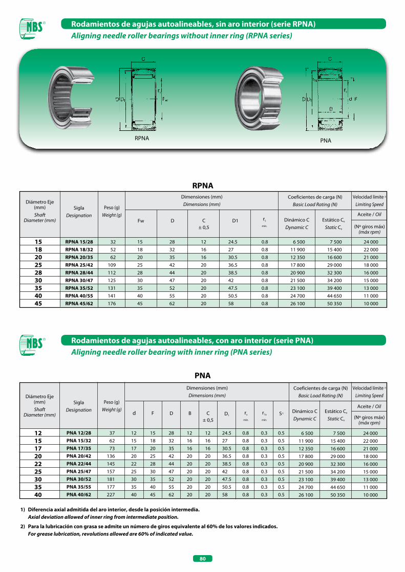
80
Rodamientos de agujas autoalineables, sin aro interior (serie RPNA)Aligning needle roller bearings without inner ring (RPNA series)
RPNA PNA
rs rs
1) Diferencia axial admitida del aro interior, desde la posición intermedia. Axial deviation allowed of inner ring from intermediate position.
2) Para la lubricación con grasa se admite un número de giros equivalente al 60% de los valores indicados. For grease lubrication, revolutions allowed are 60% of indicated value.
Diámetro Eje (mm) Shaft
Diameter (mm)
SiglaDesignation
Peso (g)Weight (g)
Dimensiones (mm)Dimensions (mm)
Coeficientes de carga (N)Basic Load Rating (N)
Dinámico CDynamic C
Estático C0
Static C0
Fw D C± 0,5
15 18 20 25 28 30 35 40 45
RPNA 15/28RPNA 18/32RPNA 20/35RPNA 25/42RPNA 28/44RPNA 30/47RPNA 35/52RPNA 40/55RPNA 45/62
32
52
62
109
112
125
131
141
176
15 28 12 24.5 0.8
18 32 16 27 0.8
20 35 16 30.5 0.8
25 42 20 36.5 0.8
28 44 20 38.5 0.8
30 47 20 42 0.8
35 52 20 47.5 0.8
40 55 20 50.5 0.8
45 62 20 58 0.8
Aceite / Oil
Velocidad límite 2)
Limiting Speed
(Nº giros máx)(máx rpm)
D1 rs
mín.
6 500 7 500 24 000
11 900 15 400 22 000
12 350 16 600 21 000
17 800 29 000 18 000
20 900 32 300 16 000
21 500 34 200 15 000
23 100 39 400 13 000
24 700 44 650 11 000
26 100 50 350 10 000
RPNA
12 15 17 20 22 25 30 35 40
Diámetro Eje (mm) Shaft
Diameter (mm)
SiglaDesignation
Peso (g)Weight (g)
Dimensiones (mm)Dimensions (mm)
Coeficientes de carga (N)Basic Load Rating (N)
Dinámico CDynamic C
Estático C0
Static C0
F D B C± 0,5
Aceite / Oil
Velocidad límite 2)
Limiting Speed
(Nº giros máx)(máx rpm)
D1 S1)rs
mín.
r1s
mín.
d
6 500 7 500 24 000
11 900 15 400 22 000
12 350 16 600 21 000
17 800 29 000 18 000
20 900 32 300 16 000
21 500 34 200 15 000
23 100 39 400 13 000
24 700 44 650 11 000
26 100 50 350 10 000
PNA 12/28PNA 15/32PNA 17/35PNA 20/42PNA 22/44PNA 25/47PNA 30/52PNA 35/55PNA 40/62
37
62
73
136
145
157
181
177
227
12 15 28 12 12 24.5 0.8 0.3 0.5
15 18 32 16 16 27 0.8 0.3 0.5
17 20 35 16 16 30.5 0.8 0.3 0.5
20 25 42 20 20 36.5 0.8 0.3 0.5
22 28 44 20 20 38.5 0.8 0.3 0.5
25 30 47 20 20 42 0.8 0.3 0.5
30 35 52 20 20 47.5 0.8 0.3 0.5
35 40 55 20 20 50.5 0.8 0.3 0.5
40 45 62 20 20 58 0.8 0.3 0.5
PNA
Rodamientos de agujas autoalineables, con aro interior (serie PNA)Aligning needle roller bearing with inner ring (PNA series)

RODAMIENTOS DE AGUJAS COMBINADOSCOMBINED NEEDLE ROLLER BEARINGS

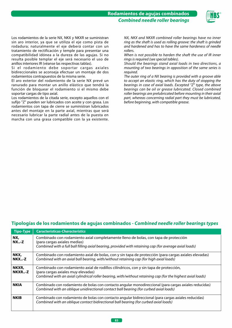
83
Rodamientos de agujas combinadosCombined needle roller bearings
Los rodamientos de la serie NX, NKX y NKXR se suministran sin aro interior, ya que se utiliza el eje como pista de rodadura; naturalmente el eje deberá contar con un tratamiento de rectificación y temple para presentar una compatibilidad idónea a la dureza de las agujas. Si no resulta posible templar el eje será necesario el uso de anillos interiores IR (véanse las respectivas tablas).S i e l rodamiento debe sopor tar cargas axiales bidireccionales se aconseja efectuar un montaje de dos rodamientos contrapuestos de la misma serie. El aro exterior del rodamiento de la serie NX prevé un ranurado para montar un anillo elástico que tendrá la función de bloquear el rodamiento si el mismo debe soportar cargas de tipo axial.Los rodamientos de la citada serie, excepto aquellos con el sufijo "Z" pueden ser lubricados con aceite y con grasa. Los rodamientos con tapa de cierre se suministran lubricados antes del montaje en la parte axial, mientras que será necesario lubricar la parte radial antes de la puesta en marcha con una grasa compatible con la ya existente.
Tipologías de los rodamientos de agujas combinados - Combined needle roller bearings types
Nx, Combinado con rodamiento axial completamente lleno de bolas, con tapa de protecciónNx..-Z (para cargas axiales medias) Combined with a full ball filling axial bearing, provided with retaining cap (for average axial loads)
NKx, Combinado con rodamiento axial de bolas, con y sin tapa de protección (para cargas axiales elevadas)NKx..-Z Combined with an axial ball bearing, with/without retaining cap (for high axial loads)
NKxR, Combinado con rodamiento axial de rodillos cilíndricos, con y sin tapa de protección,NKxR..-Z (para cargas axiales muy elevadas) Combined with an axial cylindrical roller bearing, with/without retaining cap (for the highest axial loads)
NKIA Combinado con rodamiento de bolas con contacto angular monodireccional (para cargas axiales reducidas) Combined with an oblique unidirectional contact ball bearing (for curbed axial loads)
NKIB Combinado con rodamiento de bolas con contacto angular bidireccional (para cargas axiales reducidas) Combined with an oblique contact bidirectional ball bearing (for curbed axial loads)
Tipo-Type Características-Characteristics
NX, NKX and NKXR combined roller bearings have no inner ring as the shaft is used as rolling groove: the shaft is grinded and hardened and has to have the same hardeness of needle rollers.When is not possible to harden the shaft the use of IR inner rings is required (see special tables).Should the bearings stand axial loads in two directions, a mounting of two bearings in opposition of the same series is required.The outer ring of a NX bearing is provided with a groove able to accept an elastic ring, which has the duty of stopping the bearings in case of axial loads. Excepted “Z” type, the above bearings can be oil or grease lubricated. Closed combined roller bearings are prelubricated before mounting in their axial part, whereas concerning radial part they must be lubricated, before beginning, with compatible grease.
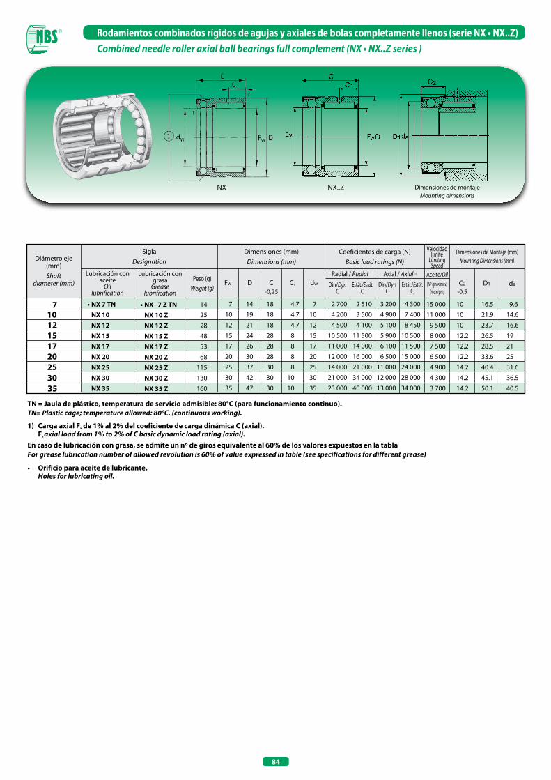
84
Rodamientos combinados rígidos de agujas y axiales de bolas completamente llenos (serie NX • NX..Z)Combined needle roller axial ball bearings full complement (NX • NX..Z series )
TN = Jaula de plástico, temperatura de servicio admisible: 80°C (para funcionamiento continuo).TN= Plastic cage; temperature allowed: 80°C. (continuous working).
1) Carga axial Fa de 1% al 2% del coeficiente de carga dinámica C (axial). Fa axial load from 1% to 2% of C basic dynamic load rating (axial).En caso de lubricación con grasa, se admite un nº de giros equivalente al 60% de los valores expuestos en la tablaFor grease lubrication number of allowed revolution is 60% of value expressed in table (see specifications for different grease)
• Orificio para aceite de lubricante. Holes for lubricating oil.
Diámetro eje (mm) Shaft
diameter (mm)
Dimensiones (mm)Dimensions (mm)
Coeficientes de carga (N)Basic load ratings (N)
D
7
12
• NX 7 TN Nx 10 Nx 12 Nx 15 Nx 17 Nx 20 Nx 25 Nx 30 Nx 35
7 14 18 4.7 7
10 19 18 4.7 10
12 21 18 4.7 12
15 24 28 8 15
17 26 28 8 17
20 30 28 8 20
25 37 30 8 25
30 42 30 10 30
35 47 30 10 35
10
15
Aceite/Oil
Velocidad limite
Limiting Speed
SiglaDesignation
Lubricación con aceite
Oil lubrification
C C1 dw
Radial / Radial
17 20 25 30 35
FwPeso (g)
Weight (g)
14
25
28
48
53
68
115
130
160
Axial / Axial 1)
da
Dimensiones de Montaje (mm)Mounting Dimensions (mm)
Lubricación con grasa
Greaselubrification
• NX 7 Z TN Nx 10 Z Nx 12 Z Nx 15 Z Nx 17 Z Nx 20 Z Nx 25 Z Nx 30 Z Nx 35 Z
D1C2
2 700 2 510 3 200 4 300
4 200 3 500 4 900 7 400
4 500 4 100 5 100 8 450
10 500 11 500 5 900 10 500
11 000 14 000 6 100 11 500
12 000 16 000 6 500 15 000
14 000 21 000 11 000 24 000
21 000 34 000 12 000 28 000
23 000 40 000 13 000 34 000
15 000 10 16.5 9.6
11 000 10 21.9 14.6
9 500 10 23.7 16.6
8 000 12.2 26.5 19
7 500 12.2 28.5 21
6 500 12.2 33.6 25
4 900 14.2 40.4 31.6
4 300 14.2 45.1 36.5
3 700 14.2 50.1 40.5
Din/DynC
Estát./Estát.Co
Din/DynC
Estát./Estát.Co
(Nº giros máx)(máx rpm)-0,25 -0,5
NX NX..Z Dimensiones de montajeMounting dimensions
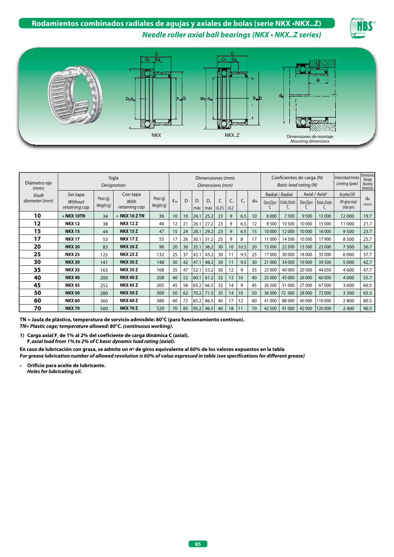
85
Rodamientos combinados radiales de agujas y axiales de bolas (serie NKX •NKX..Z)Needle roller axial ball bearings (NKX • NKX..Z series)
Diámetro eje (mm) Shaft
diameter (mm)
Dimensiones (mm)Dimensions (mm)
Coeficientes de carga (N)Basic load rating (N)
D
10
15
• NKx 10TN
NKx 12
NKx 15
NKx 17
NKx 20
NKx 25
NKx 30
NKx 35
NKx 40
NKx 45
NKx 50
NKx 60
NKx 70
34
38
44
53
83
125
141
163
200
252
280
360
500
10 19 24.1 25.2 23 9 6.5 10
12 21 26.1 27.2 23 9 6.5 12
15 24 28.1 29.2 23 9 6.5 15
17 26 30.1 31.2 25 9 8 17
20 30 35.1 36.2 30 10 10.5 20
25 37 42.1 43.2 30 11 9.5 25
30 42 47.1 48.2 30 11 9.5 30
35 47 52.1 53.2 30 12 9 35
40 52 60.1 61.2 32 13 10 40
45 58 65.2 66.5 32 14 9 45
50 62 70.2 71.5 35 14 10 50
60 72 85.2 86.5 40 17 12 60
70 85 95.2 96.5 40 18 11 70
12
17
Velocidad limiteLimiting Speed
SiglaDesignation
Sin tapaWithout
retaining capC C1 C2D1 D2 dw
Radial / Radial
20 25 30 35 40
Fw
Con tapaWith
retaining cap
36
40
47
55
90
132
148
168
208
265
300
380
520
6 000 7 500 9 500 13 000
8 500 10 500 10 000 15 000
10 000 12 000 10 000 16 000
11 000 14 500 10 500 17 900
15 000 22 500 13 500 23 000
17 000 30 000 18 000 35 000
21 000 34 000 19 000 39 500
23 000 40 000 20 500 44 650
25 000 45 000 26 000 60 000
26 500 51 000 27 000 67 000
36 000 72 000 28 000 72 000
41 000 88 000 40 000 110 000
42 500 91 000 42 000 120 000
Axial / Axial 1)
da(mm)
Dimensiones Montaje
MountingDimensions
12 000 19.7
11 000 21.7
9 500 23.7
8 500 25.7
7 500 30.7
6 000 37.7
5 000 42.7
4 600 47.7
4 000 55.7
3 600 60.5
3 300 65.5
2 800 80.5
2 400 90.5
TN = Jaula de plástico, temperatura de servicio admisible: 80°C (para funcionamiento continuo).TN= Plastic cage; temperature allowed: 80°C. (continuous working).
1) Carga axial Fa de 1% al 2% del coeficiente de carga dinámica C (axial). Fa axial load from 1% to 2% of C basic dynamic load rating (axial).En caso de lubricación con grasa, se admite un nº de giros equivalente al 60% de los valores expuestos en la tablaFor grease lubrication number of allowed revolution is 60% of value expressed in table (see specifications for different grease)
• Orificio para aceite de lubricante. Holes for lubricating oil.
45 50 60 70
• NKx 10 Z TN
NKx 12 Z
NKx 15 Z
NKx 17 Z
NKx 20 Z
NKx 25 Z
NKx 30 Z
NKx 35 Z
NKx 40 Z
NKx 45 Z
NKx 50 Z
NKx 60 Z
NKx 70 Z
Peso (g)Weight (g)
Peso (g)Weight (g) Din/Dyn
CEstát./Estát.
Co
Din/DynC
Estát./Estát.Co máx máx -0,25 -0,2
Aceite/Oil(Nº giros máx)
(máx rpm)
NKX..ZNKX Dimensiones de montajeMounting dimensions
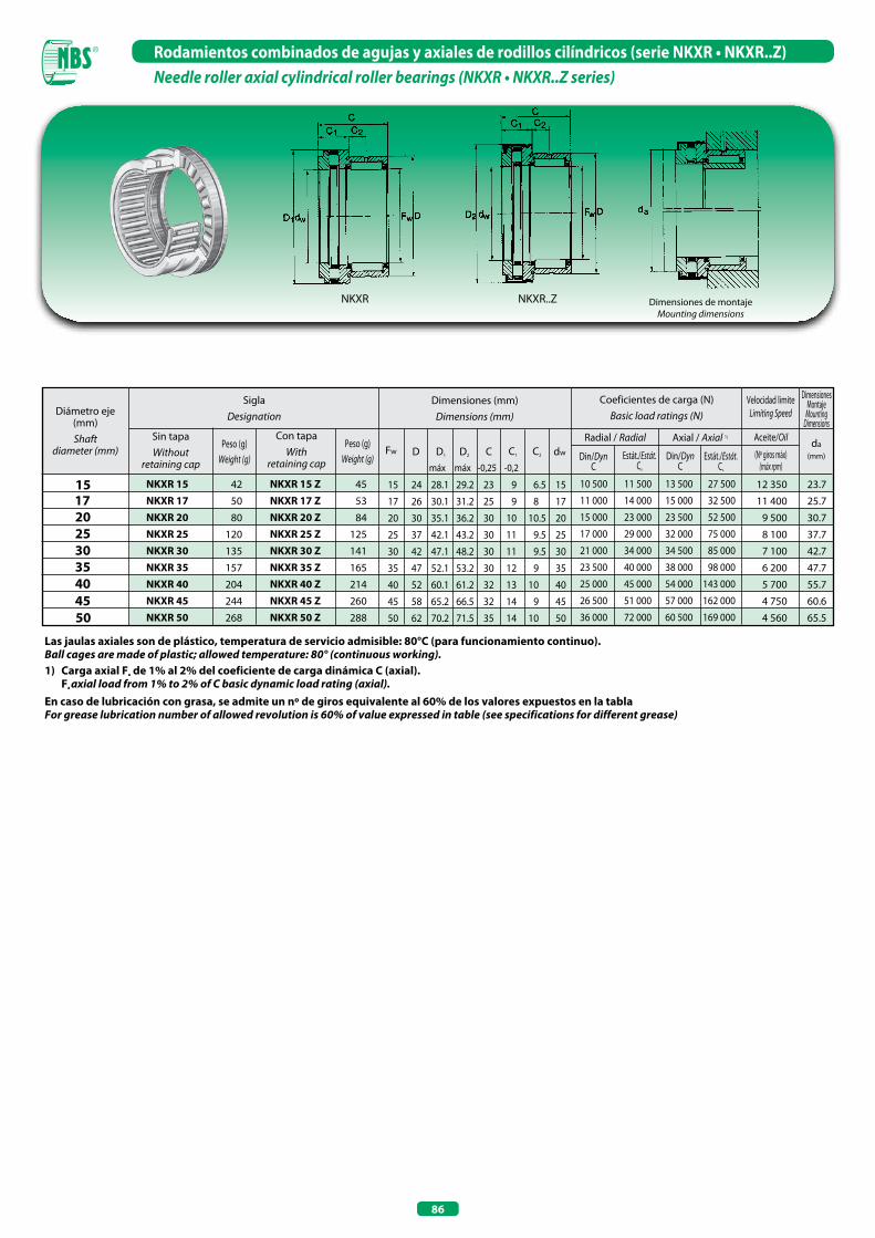
86
Rodamientos combinados de agujas y axiales de rodillos cilíndricos (serie NKXR • NKXR..Z)Needle roller axial cylindrical roller bearings (NKXR • NKXR..Z series)
Las jaulas axiales son de plástico, temperatura de servicio admisible: 80°C (para funcionamiento continuo).Ball cages are made of plastic; allowed temperature: 80° (continuous working).1) Carga axial Fa de 1% al 2% del coeficiente de carga dinámica C (axial). Fa axial load from 1% to 2% of C basic dynamic load rating (axial).En caso de lubricación con grasa, se admite un nº de giros equivalente al 60% de los valores expuestos en la tablaFor grease lubrication number of allowed revolution is 60% of value expressed in table (see specifications for different grease)
Diámetro eje (mm) Shaft
diameter (mm)
Dimensiones (mm)Dimensions (mm)
Coeficientes de carga (N)Basic load ratings (N)
D
15
20
NKxR 15NKxR 17NKxR 20NKxR 25NKxR 30NKxR 35NKxR 40NKxR 45NKxR 50
42
50
80
120
135
157
204
244
268
15 24 28.1 29.2 23 9 6.5 15
17 26 30.1 31.2 25 9 8 17
20 30 35.1 36.2 30 10 10.5 20
25 37 42.1 43.2 30 11 9.5 25
30 42 47.1 48.2 30 11 9.5 30
35 47 52.1 53.2 30 12 9 35
40 52 60.1 61.2 32 13 10 40
45 58 65.2 66.5 32 14 9 45
50 62 70.2 71.5 35 14 10 50
17
25
Velocidad limiteLimiting Speed
SiglaDesignation
Sin tapaWithout
retaining cap
Peso (g)Weight (g)
CD1 D2 C1 C2 dw
Radial / Radial
30 35 40 45 50
Fw
Con tapaWith
retaining cap
NKxR 15 ZNKxR 17 ZNKxR 20 ZNKxR 25 ZNKxR 30 ZNKxR 35 ZNKxR 40 ZNKxR 45 ZNKxR 50 Z
45
53
84
125
141
165
214
260
288
10 500 11 500 13 500 27 500
11 000 14 000 15 000 32 500
15 000 23 000 23 500 52 500
17 000 29 000 32 000 75 000
21 000 34 000 34 500 85 000
23 500 40 000 38 000 98 000
25 000 45 000 54 000 143 000
26 500 51 000 57 000 162 000
36 000 72 000 60 500 169 000
Axial / Axial 1)
da(mm)
Dimensiones Montaje
MountingDimensions
12 350 23.7
11 400 25.7
9 500 30.7
8 100 37.7
7 100 42.7
6 200 47.7
5 700 55.7
4 750 60.6
4 560 65.5
Peso (g)Weight (g) Din/Dyn
CEstát./Estát.
Co
Din/DynC
Estát./Estát.Co máx máx -0,25 -0,2
Aceite/Oil
(Nº giros máx)(máx rpm)
NKXR..ZNKXR Dimensiones de montajeMounting dimensions
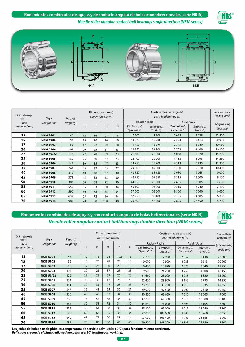
87
Rodamientos combinados de agujas y de contacto angular de bolas monodireccionales (serie NKIA)Needle roller angular contact ball bearings single direction (NKIA series)
Las jaulas de bolas son de plástico, temperatura de servicio admisible: 80°C (para funcionamiento continuo).Ball cages are made of plastic; allowed temperature: 80° (continuous working).
Diámetro eje (mm) Shaft
diameter (mm)
Dimensiones (mm)Dimensions (mm)
Coeficientes de carga (N)Basic load ratings (N)
d F
12
17
NKIA 5901NKIA 5902NKIA 5903NKIA 5904NKIA 59/22NKIA 5905NKIA 5906NKIA 5907NKIA 5908NKIA 5909NKIA 5910NKIA 5911NKIA 5912NKIA 5913NKIA 5914
40
50
56
103
118
130
147
243
315
375
380
550
590
635
980
12 16 24 16
15 20 28 18
17 22 30 18
20 25 37 23
22 28 39 23
25 30 42 23
30 35 47 23
35 42 55 27
40 48 62 30
45 52 68 30
50 58 72 30
55 63 80 34
60 68 85 34
65 72 90 34
70 80 100 40
7 200 7 900 2 052 2 138 22 800
10 070 12 900 2 223 2 613 20 900
10 450 13 870 2 375 3 040 19 950
19 950 24 200 3 753 4 608 16 150
21 660 28 000 4 038 5 320 15 200
22 400 29 900 4 133 5 795 14 250
23 750 33 700 4 513 6 935 12 350
29 900 47 500 5 700 9 310 10 450
40 850 63 650 7 030 12 065 9 000
42 750 69 350 7 315 13 300 8 100
44 650 76 000 7 695 15 105 7 600
55 100 95 000 9 215 18 240 7 100
57 000 102 600 9 500 10 260 6 650
57 950 106 400 9 785 21 185 6 200
79 800 148 200 12 825 27 550 5 700
15
20
55
(Nº giros máx)(máx rpm)
Velocidad limiteLimiting Speed
SiglaDesignation
Peso (g)Weight (g)
D BAxial / Axial
22 25 30 35 40 45 50
Dinámico CDynamic C
Estático Co
Static Co
60 65 70
Radial / RadialDinámico CDynamic C
Estático Co
Static Co
NKIA
Diámetro eje (mm) Shaft
diameter (mm)
Dimensiones (mm)Dimensions (mm)
Coeficientes de carga (N)Basic load ratings (N)
d F
12
17
NKIB 5901NKIB 5902NKIB 5903NKIB 5904NKIB 59/22NKIB 5905NKIB 5906NKIB 5907NKIB 5908NKIB 5909NKIB 5910NKIB 5911NKIB 5912NKIB 5913NKIB 5914
43
52
58
107
122
134
151
247
320
380
385
555
595
640
985
12 16 24 17.5 16
15 20 28 20 18
17 22 30 20 18
20 25 37 25 23
22 28 39 25 23
25 30 42 25 23
30 35 47 25 23
35 42 55 30 27
40 48 62 34 30
45 52 68 34 30
50 58 72 34 30
55 63 80 38 34
60 68 85 38 34
65 72 90 38 34
70 80 100 45 40
7 200 7 900 2 052 2 138 22 800
10 070 12 900 2 223 2 613 20 900
10 450 13 870 2 375 3 040 19 950
19 950 24 200 3 753 4 608 16 150
21 660 28 000 4 038 5 320 15 200
22 400 29 900 4 133 5 795 14 250
23 750 33 700 4 513 6 935 12 350
29 900 47 500 5 700 9 310 10 450
40 850 63 650 7 030 12 065 9 000
42 750 69 350 7 315 13 300 8 100
44 650 76 000 7 695 15 105 7 600
55 100 95 000 9 215 18 240 7 100
57 000 102 600 9 500 10 260 6 650
57 950 106 400 9 785 21 185 6 200
79 800 148 200 12 825 27 550 5 700
15
20
55
(Nº giros máx)(máx rpm)
Velocidad limiteLimiting SpeedSigla
DesignationPeso (g)
Weight (g)D B
22 25 30 35 40 45 50
60 65 70
CAxial / Axial
Dinámico CDynamic C
Estático Co
Static Co
Radial / RadialDinámico CDynamic C
Estático Co
Static Co
Rodamientos combinados de agujas y con contacto angular de bolas bidireccionales (serie NKIB)Needle roller angular contact ball bearings double direction (NKIB series)
NKIB

AROS INTERIORESINNER RINGS

91
Aros interiores Inner rings
Los aros interiores para los rodamientos de agujas NBS constituyen una opción de elevada precisión y económicamente ventajosa, cuando no resulta posible utilizar el eje como camino de rodadura del rodamiento. Los aros interiores se suministran con diversos anchos y en dos series distintas: IR y LR.La diferencia fundamental es que los aros IR cuentan con un acabado de mayor calidad, mientras que los LR, más económicos, se utilizan generalmente combinados con rodamientos con y sin fondo.Ambos tipos de aros cuentan con chaflanes que facilitan su montaje. Los aros interiores IR están disponibles también en otras configuraciones, según las exigencias de los clientes, como por ejemplo con una mayor precisión (clase de tolerancia P5 y P6), un juego diferente del estándar (C2 - C3 - C4) y con agujero de engrase. Los aros interiores LR cuentan con un temple y un acabado de precisión, si bien sus superficies laterales no están rectificadas. No se suministran con diseños especiales diferentes al estándar.
Tipologías de los aros interiores - Inner ring types
IR Con tolerancias según las normas DIN. With tolerance conforming to DIN rules.
LR Con tolerancias más amplias. With wider tolerances
Tipo-Type Características-Characteristics
NBS inner rings offer the possibility to adopt more advantageous and correct solutions when the shaft cannot be used as a rolling groove for the bearing.Inner rings are available with different width and in two different series: IR and LR.IR are well finished whereas LR are cheaper and usually combined with bearings open or closed end, both rings are supplied with a chamfer to facilitate their mounting.IR rings are available in different versions as per customers requirements: greater precision (P5 and P6 tolerance class), C2-C3-C4 radial clearance and with lubrication hole.LR rings are hardened and well finished even if lateral surfaces are not grinded; special executions are not available, only standard types.

92
Aros interiores (serie IR • LR)Inner rings (IR • LR series)
n Orificio de lubricación de serie - With lubrication hole. Si no está indicado lo contrario están disponibles también con orificio de lubricación - Where it is not specified, under request available also with lubrication hole1) Valor medio entre el diámetro mayor y el menor - Average between bigger and smaller diameter.
Diámetro eje (mm) Shaft
diameter (mm)
Dimensiones (mm)Dimensions (mm)
d F
5
SiglaDesignation
Peso (g) Weight (g)
B
6
7
8
9
10
12
14
15
Diámetro eje (mm) Shaft
diameter (mm)
Dimensiones (mm)Dimensions (mm)
IR - IR - IR - IR - IR LR IR - IR LR IR LR IR - IR - IR - IR - IR - IR - IR - IR - IR - IR - - LR n IR - - LR IR - IR - IR - IR LR IR LR IR - IR LR IR - IR - IR - IR - IR - IR LR IR - IR - IR - - LR n IR - - LR
13.5
14.7
24.4
10.7
11.1
13.5
13.8
20.6
14.3
18
14.9
16.4
18.7
23
27.1
33.6
16.5
21.3
16.3
21.1
21.7
22.4
24.3
27.5
28.2
36.1
40.9
52.5
45.2
17.5
23.2
29.8
35
36
54.4
25.5
39.3
20
26
26.7
15 20 13
15 20 14
15 20 23
17 20 16
17 20 16.5
17 20 20
17 20 20.5
17 20 30.5
17 21 16
17 21 20
17 22 13
17 22 14
17 22 16
17 22 20
17 22 23
17 24 20
20 24 16
20 24 20
20 25 12.5
20 25 16
20 25 16.5
20 25 17
20 25 18
20 25 20
20 25 20.5
20 25 26.5
20 25 30
20 25 38.5
20 28 20
22 26 16
22 26 20
22 28 17
22 28 20
22 28 20.5
22 28 30
25 29 20
25 29 30
25 30 12.5
25 30 16
25 30 16.5
SiglaDesignation
Peso (g)Weight (g)
15
17
20
22
25
d F B
2.79
3.75
3.17
4.3
3.7
4.6
3.09
3.61
4.9
4.8
5
5.7
5.9
4.5
6.1
5.2
7.3
7.4
8
9.2
11.6
5.8
6.1
8
8.1
10.9
7
7.9
8.7
9.5
10.9
13.5
14.9
10
7.2
9.6
9.9
12.8
16.4
12.1
IR - IR - IR - IR - n IR - IR - IR LR IR - IR - n IR - IR LR IR - IR LR IR - IR - IR LR n IR - IR - IR - IR - IR - IR - IR LR IR - IR LR IR LR IR - n IR - IR - IR - IR - IR - IR - IR - - LR IR - IR LR IR - IR - n IR -
5 8 12
5 8 16
6 9 12
6 9 16
6 10 10
6 10 12
7 10 10.5
7 10 12
7 10 16
8 12 10
8 12 10.5
8 12 12
8 12 12.5
9 12 12
9 12 16
10 13 12.5
10 14 12
10 14 13
10 14 14
10 14 16
10 14 20
12 15 12
12 15 12.5
12 15 16
12 15 16.5
12 15 22.5
12 16 10
12 16 12
12 16 13
12 16 14
12 16 16
12 16 20
12 16 22
14 17 17
15 18 12.5
15 18 16
15 18 16.5
15 19 16
15 19 20
15 20 12
LRIR
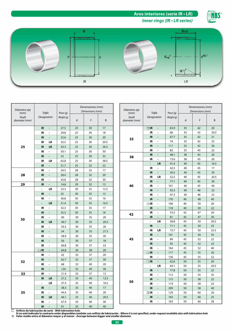
93
Aros interiores (serie IR • LR)Inner rings (IR • LR series)
Diámetro eje (mm) Shaft
diameter (mm)
Dimensiones (mm)Dimensions (mm)Sigla
DesignationPeso (g)
Weight (g)d F B
Diámetro eje (mm) Shaft
diameter (mm)
Dimensiones (mm)Dimensions (mm)Sigla
DesignationPeso (g)
Weight (g)d F B
25
28
n IR - IR - IR - IR - IR - IR - IR - IR - - LR IR - IR - IR LR IR - IR - IR - IR - IR - n IR - IR - IR - IR - - LR IR - IR LR IR - IR - IR - IR - n IR - IR - n IR - - LR IR - IR - IR - IR - IR - n IR - IR - IR -
63.9
66
67.7
74
117
82
48.1
73.6
41.4
42.5
50.5
52.5
77.1
101
92.3
97.3
170
106
118
53.5
81
58.8
71.1
73.7
101
89
93
164
117
130
62.6
64.1
77.8
112
115
119
209
129
163
183
35 42 20
35 42 20.5
35 42 21
35 42 23
35 42 36
35 43 22
38 43 20
38 43 30
40 45 16.5
40 45 17
40 45 20
40 45 20.5
40 45 30
40 45 40
40 48 22
40 48 23
40 48 40
40 50 20
40 50 22
42 47 20
42 47 30
45 50 20.5
45 50 25
45 50 25.5
45 50 35
45 52 22
45 52 23
45 52 40
45 55 20
45 55 22
50 55 20
50 55 20.5
50 55 25
50 55 35
50 58 22
50 58 23
50 58 40
50 60 20
50 60 25
50 60 28
32
29
30
40
42
45
50
IR -
IR -
IR -
IR LR
IR LR
IR -
IR -
IR LR
IR -
IR -
IR -
IR -
IR -
- LR
IR -
IR -
- LR
IR -
IR -
IR -
IR LR
IR -
IR -
IR -
IR -
IR -
n IR -
IR -
IR -
IR -
IR -
IR -
IR LR
- LR
IR -
IR -
IR LR
IR -
IR -
27.5
29.8
32.6
33.5
43.3
50.1
53
63.8
51.7
24.5
28.4
43.8
14.8
23.3
25
30.8
31.4
32.3
35.3
40
40.7
50.3
54
58.9
50
60.8
64.8
42
62.7
68
124
21.9
27.2
37.4
38.3
44.4
46.1
67.9
91
25 30 17
25 30 18
25 30 20
25 30 20.5
25 30 26.5
25 30 30
25 30 32
25 30 38.5
25 32 22
28 32 17
28 32 20
28 32 30
29 32 13
30 35 12.5
30 35 13
30 35 16
30 35 16.5
30 35 17
30 35 18
30 35 20
30 35 20.5
30 35 26
30 35 27.5
30 35 30
30 37 18
30 37 22
30 38 20
32 37 20
32 37 30
32 40 20
32 40 36
33 37 13
35 40 12.5
35 40 16.5
35 40 17
35 40 20
35 40 20.5
35 40 30
35 40 40
33
38
35
35
LRIR
n Orificio de lubricación de serie - With lubrication hole. Si no está indicado lo contrario están disponibles también con orificio de lubricación - Where it is not specified, under request available also with lubrication hole1) Valor medio entre el diámetro mayor y el menor - Average between bigger and smaller diameter.
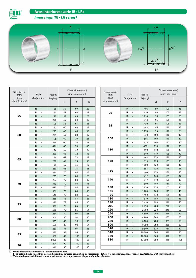
94
Aros interiores (serie IR • LR)Inner rings (IR • LR series)
Diámetro eje (mm) Shaft
diameter (mm)
Dimensiones (mm)Dimensions (mm)Sigla
DesignationPeso (g)
Weight (g)
d F B
IR - IR - IR - IR - IR - IR - IR - IR - IR - IR - IR - IR - IR - IR - IR - IR - IR - IR - IR - IR - IR - IR - IR - IR - IR - IR - IR - IR - IR - IR - IR - IR - IR - IR - IR - IR - IR - IR -
86
121
141
256
198
152
213
275
195
216
496
142
259
164
232
99
230
224
253
267
313
487
506
548
238
287
336
520
254
304
355
550
280
390
580
1 050
294
340
55 60 25
55 60 35
55 63 25
55 63 45
55 65 28
60 68 25
60 68 35
60 68 45
60 70 25
60 70 28
60 70 60
65 72 25
65 72 45
65 73 25
65 73 35
65 75 12
65 75 28
70 80 25
70 80 28
70 80 30
70 80 35
70 80 54
70 80 56
70 80 60
75 85 25
75 85 30
75 85 35
75 85 54
80 90 25
80 90 30
80 90 35
80 90 54
85 95 26
85 95 36
85 100 35
85 100 63
90 100 26
90 100 30
IR - IR - IR - IR - IR - IR - IR - IR - IR - IR - IR - IR - IR - IR - IR - IR - IR - IR - IR - IR - IR - IR - IR - IR - IR - IR - IR - IR - IR - IR - IR - IR - IR - IR - IR - IR -
406
610
1 110
313
430
643
1 170
370
505
775
409
690
840
442
815
1 000
855
1 690
412
917
1 800
1 120
1 200
1 450
1 510
2 410
2 490
2 750
4 600
4 980
6 100
9 200
9 800
10 200
10 900
17 000
70
80
55
60
65
75
85
90
95
100
110
120
130
140
150160
Diámetro eje (mm) Shaft
diameter (mm)
Dimensiones (mm)Dimensions (mm)Sigla
DesignationPeso (g)
Weight (g)
d F B
90
180170
190 200220240260280300320340360380
LRIR
90 100 36
90 105 35
90 105 63
95 105 26
95 105 36
95 110 35
95 110 63
100 110 30
100 110 40
100 115 40
110 120 30
110 120 40
110 125 40
120 130 30
120 135 35
120 135 45
130 145 35
130 150 50
140 155 32
140 155 35
140 160 50
150 165 40
160 175 40
170 185 45
180 195 45
190 210 50
200 220 50
220 240 50
240 265 60
260 285 60
280 305 69
300 330 80
320 350 80
340 370 80
360 390 80
380 415 100
n Orificio de lubricación de serie - With lubrication hole. Si no está indicado lo contrario están disponibles también con orificio de lubricación - Where it is not specified, under request available also with lubrication hole1) Valor medio entre el diámetro mayor y el menor - Average between bigger and smaller diameter.
CASQUILLOS DE MARCHA LIBRE
CASQUILLOS DE MARCHA LIBRE CON SOPORTE
DRAWN CUP ROLLER CLUTCHES
DRAWN CUP ROLLER CLUTCHES WITH BEARINGS ASSEMBLY

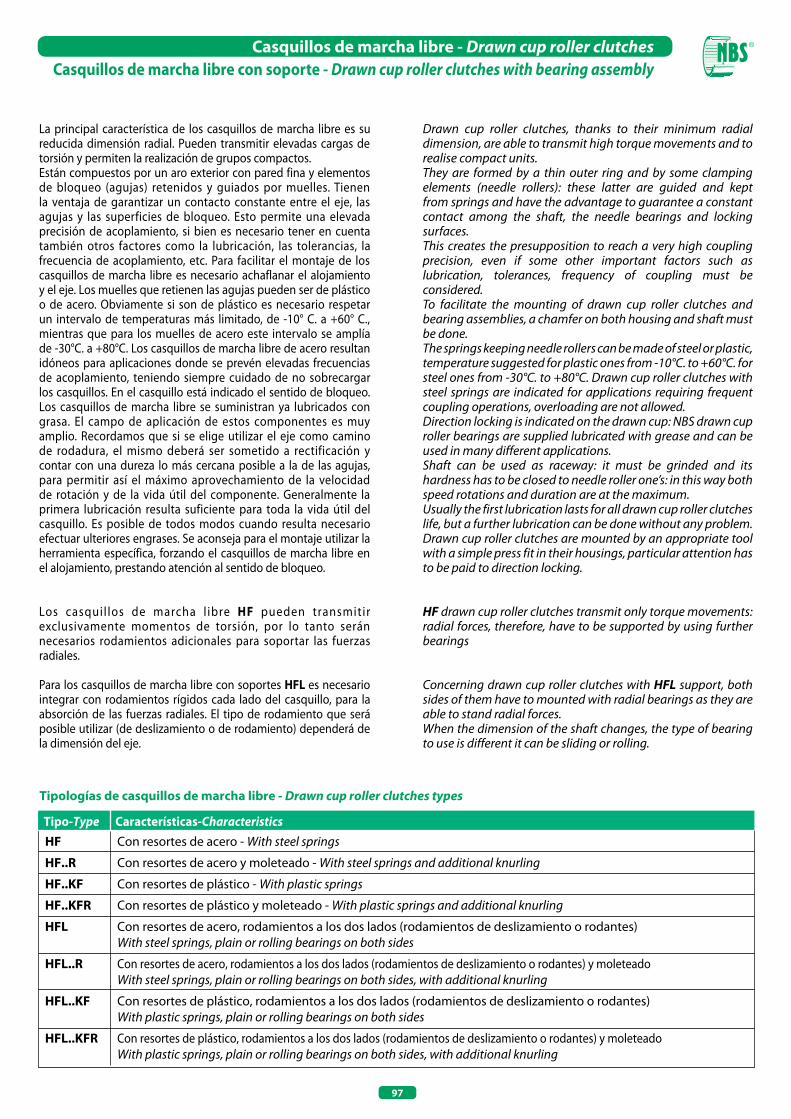
97
La principal característica de los casquillos de marcha libre es su reducida dimensión radial. Pueden transmitir elevadas cargas de torsión y permiten la realización de grupos compactos.Están compuestos por un aro exterior con pared fina y elementos de bloqueo (agujas) retenidos y guiados por muelles. Tienen la ventaja de garantizar un contacto constante entre el eje, las agujas y las superficies de bloqueo. Esto permite una elevada precisión de acoplamiento, si bien es necesario tener en cuenta también otros factores como la lubricación, las tolerancias, la frecuencia de acoplamiento, etc. Para facilitar el montaje de los casquillos de marcha libre es necesario achaflanar el alojamiento y el eje. Los muelles que retienen las agujas pueden ser de plástico o de acero. Obviamente si son de plástico es necesario respetar un intervalo de temperaturas más limitado, de -10° C. a +60° C., mientras que para los muelles de acero este intervalo se amplía de -30°C. a +80°C. Los casquillos de marcha libre de acero resultan idóneos para aplicaciones donde se prevén elevadas frecuencias de acoplamiento, teniendo siempre cuidado de no sobrecargar los casquillos. En el casquillo está indicado el sentido de bloqueo. Los casquillos de marcha libre se suministran ya lubricados con grasa. El campo de aplicación de estos componentes es muy amplio. Recordamos que si se elige utilizar el eje como camino de rodadura, el mismo deberá ser sometido a rectificación y contar con una dureza lo más cercana posible a la de las agujas, para permitir así el máximo aprovechamiento de la velocidad de rotación y de la vida útil del componente. Generalmente la primera lubricación resulta suficiente para toda la vida útil del casquillo. Es posible de todos modos cuando resulta necesario efectuar ulteriores engrases. Se aconseja para el montaje utilizar la herramienta específica, forzando el casquillos de marcha libre en el alojamiento, prestando atención al sentido de bloqueo.
Los casquil los de marcha l ibre HF pueden transmitir exclusivamente momentos de torsión, por lo tanto serán necesarios rodamientos adicionales para soportar las fuerzas radiales.
Para los casquillos de marcha libre con soportes HFL es necesario integrar con rodamientos rígidos cada lado del casquillo, para la absorción de las fuerzas radiales. El tipo de rodamiento que será posible utilizar (de deslizamiento o de rodamiento) dependerá de la dimensión del eje.
Tipo-Type Características-CharacteristicsHF
HF..R
HF..KF
HF..KFR
HFL
HFL..R
HFL..KF
HFL..KFR
Con resortes de acero - With steel springs
Con resortes de acero y moleteado - With steel springs and additional knurling
Con resortes de plástico - With plastic springs
Con resortes de plástico y moleteado - With plastic springs and additional knurling
Con resortes de acero, rodamientos a los dos lados (rodamientos de deslizamiento o rodantes)With steel springs, plain or rolling bearings on both sides
Con resortes de acero, rodamientos a los dos lados (rodamientos de deslizamiento o rodantes) y moleteadoWith steel springs, plain or rolling bearings on both sides, with additional knurling
Con resortes de plástico, rodamientos a los dos lados (rodamientos de deslizamiento o rodantes)With plastic springs, plain or rolling bearings on both sides
Con resortes de plástico, rodamientos a los dos lados (rodamientos de deslizamiento o rodantes) y moleteadoWith plastic springs, plain or rolling bearings on both sides, with additional knurling
Tipologías de casquillos de marcha libre - Drawn cup roller clutches types
Casquillos de marcha libre - Drawn cup roller clutchesCasquillos de marcha libre con soporte - Drawn cup roller clutches with bearing assembly
Drawn cup roller clutches, thanks to their minimum radial dimension, are able to transmit high torque movements and to realise compact units.They are formed by a thin outer ring and by some clamping elements (needle rollers): these latter are guided and kept from springs and have the advantage to guarantee a constant contact among the shaft, the needle bearings and locking surfaces.This creates the presupposition to reach a very high coupling precision, even if some other important factors such as lubrication, tolerances, frequency of coupling must be considered.To facilitate the mounting of drawn cup roller clutches and bearing assemblies, a chamfer on both housing and shaft must be done.The springs keeping needle rollers can be made of steel or plastic, temperature suggested for plastic ones from -10°C. to +60°C. for steel ones from -30°C. to +80°C. Drawn cup roller clutches with steel springs are indicated for applications requiring frequent coupling operations, overloading are not allowed.Direction locking is indicated on the drawn cup: NBS drawn cup roller bearings are supplied lubricated with grease and can be used in many different applications.Shaft can be used as raceway: it must be grinded and its hardness has to be closed to needle roller one’s: in this way both speed rotations and duration are at the maximum.Usually the first lubrication lasts for all drawn cup roller clutches life, but a further lubrication can be done without any problem.Drawn cup roller clutches are mounted by an appropriate tool with a simple press fit in their housings, particular attention has to be paid to direction locking.
HF drawn cup roller clutches transmit only torque movements: radial forces, therefore, have to be supported by using further bearings
Concerning drawn cup roller clutches with HFL support, both sides of them have to mounted with radial bearings as they are able to stand radial forces.When the dimension of the shaft changes, the type of bearing to use is different it can be sliding or rolling.
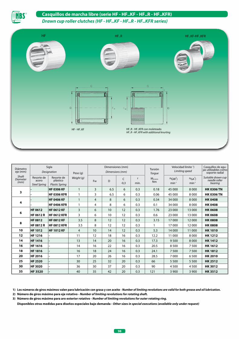
98
Casquillos de marcha libre (serie HF - HF..KF - HF..R - HF..KFR) Drawn cup roller clutches (HF - HF..KF - HF..R - HF..KFR series)
1) Los números de giros máximos valen para lubricación con grasa y con aceite - Number of limiting revolutions are valid for both grease and oil lubrication. 2) Número de giros máximo para eje rotativo - Number of limiting revolutions for rotating shaft.3) Número de giros máximo para aro exterior rotativo - Number of limiting revolutions for outer rotating ring.
Disponibles otras medidas para diseños especiales bajo demanda - Other sizes in special executions (available only under request)
HF HF..KF-HF..KFRHF..R
Diámetro eje (mm)
ShaftDiameter
(mm)
Sigla
Designation Peso (g)
Weight (g)
Dimensiones (mm)
Dimensions (mm)TorsiónTorgue
Md amm
Nm
Velocidad límite 1)Limiting speed
Casquillos de agu-jas utilizables como
soporte radial
Suitable drawn cup needle roller
bearing
Resorte de acero
Steel Spring
Resorte de plástico
Plastic SpringFw D
C-0,3
r
mín.
nGW2)min-1
nGA3)
min-1
3- HF 0306 KF 1 3 6.5 6 0.3 0.18 45 000 8 000 HK 0306 TN- HF 0306 KFR 1 3 6.5 6 0.3 0.06 45 000 8 000 HK 0306 TN
4- HF 0406 KF 1 4 8 6 0.3 0.34 34 000 8 000 HK 0408- HF 0406 KFR 1 4 8 6 0.3 0.1 34 000 8 000 HK 0408
6HF 0612 HF 0612 KF 3 6 10 12 0.3 1.76 23 000 13 000 HK 0608HF 0612 R HF 0612 KFR 3 6 10 12 0.3 0.6 23 000 13 000 HK 0608
8HF 0812 HF 0812 KF 3.5 8 12 12 0.3 3.15 17 000 12 000 HK 0808HF 0812 R HF 0812 KFR 3.5 8 12 12 0.3 1 17 000 12 000 HK 0808
10 HF 1012 HF 1012 KF 4 10 14 12 0.3 5.3 14 000 11 000 HK 101012 HF 1216 - 11 12 18 16 0.3 12.2 11 000 8 000 HK 121214 HF 1416 - 13 14 20 16 0.3 17.3 9 500 8 000 HK 141216 HF 1616 - 14 16 22 16 0.3 20.5 8 500 7 500 HK 161218 HF 1816 - 16 18 24 16 0.3 24.1 7 500 7 500 HK 181220 HF 2016 - 17 20 26 16 0.3 28.5 7 000 6 500 HK 201025 HF 2520 - 30 25 32 20 0.3 66 5 500 5 500 HK 251230 HF 3020 - 36 30 37 20 0.3 90 4 500 4 500 HK 301235 HF 3520 - 40 35 42 20 0.3 121 3 900 3 900 HK 3512
HF - HF..KF HF..R - HF..KFR con moleteadoHF..R - HF..KFR with additional knurting

99
Casquillos de marcha libre con soportes (serie HFL - HFL..KF - HFL..R - HFL..KFRDrawn cup roller clutches with bearing assemblies (HFL - HFL..KF - HFL..R - HFL..KFR series)
Diámetro eje (mm)
ShaftDiameter
(mm)
Sigla
Designation Peso (g)
Weight (g)
Dimensiones (mm)
Dimensions (mm)TorsiónTorgue
Md amm
Nm
Velocidad límite 1)Limiting speed
Coeficientes de cargaBasic load ratings
Resorte de aceroSteel Spring
Resorte de plástico
Plastic SpringFw D
C-0,3
r
mín.
nGW2)min-1
nGA3)
min-1
din. Cdin. C
N
estat. C0
stat. C0N
3- HFL 0308 KF 1.4 3 6.5 8 0.3 0.18 45 000 8 000 - -- HFL 0308 KFR 1.4 3 6.5 8 0.3 0.06 45 000 8 000 - -
4- HFL 0408 KF 1.6 4 8 8 0.3 0.34 34 000 8 000 - -- HFL 0408 KFR 1.6 4 8 8 0.3 0.1 34 000 8 000 - -
6
- HFL 0606 KFR 1 6 10 6 0.3 0.5 23 000 13 000 - -HFL 0615 HFL 0615 KF 4 6 10 15 0.3 1.76 23 000 13 000 - -HFL 0615 R HFL 0615 KFR 4 6 10 15 0.3 0.60 23 000 13 000 - -
8
- HFL 0806 KFR 2 8 12 6 0.3 0.7 17 000 12 000 - -HFL 0822 HFL 0822 KF 7 8 12 22 0.3 3.15 17 000 12 000 3 650 3 950HFL 0822 R HFL 0822 KFR 7 8 12 22 0.3 1 17 000 12 000 3 650 3 950
10 HFL 1022 - 8 10 14 22 0.3 5.3 14 000 11 000 3 950 4 500
12 HFL 1226 - 18 12 18 26 0.3 12.2 11 000 8 000 6 300 6 700
14 HFL 1426 - 20 14 20 26 0.3 17.3 9 500 8 000 6 800 7 800
16 HFL 1626 - 22 16 22 26 0.3 20.5 8 500 7 500 7 400 9 000
18 HFL 1826 - 25 18 24 26 0.3 24.1 7 500 7 500 8 000 10 200
20 HFL 2026 - 27 20 26 26 0.3 28.5 7 000 6 500 8 500 11 400
25 HFL 2530 - 44 25 32 30 0.3 66 5 500 5 500 10 600 14 000
30 HFL 3030 - 51 30 37 30 0.3 90 4 500 4 500 11 600 16 900
35 HFL 3530 - 58 35 42 30 0.3 121 3 900 3 900 12 200 18 800
1) Los números de giros máximos valen para lubricación con grasa y con aceite - Number of limiting revolutions are valid for both grease and oil lubrication. 2) Número de giros máximo para eje rotativo - Number of limiting revolutions for rotating shaft.3) Número de giros máximo para aro exterior rotativo - Number of limiting revolutions for outer rotating ring.
Disponibles otras medidas para diseños especiales bajo demanda - Other sizes in special executions (available only under request)
HFL HFL...KF-HFL..KFRHFL...R
HFL, HFL..KF con rodamiento de desli-zamientoHFL, HFL..KF with plain bearing
HFL, HFL..KF con rodamiento rodanteHFL, HFL..KF with rolling bearing
HFL 06 06 KFRHFL 08 06 KFRsin flecha en el lado frontalno arrow on the frontcon moleteadowith additional knurting
HFL 04 08 KFRHFL 06 15 KFRcon moleteadowith additional knurting

RODAMIENTOS AxIALES DE RODILLOS CILÍNDRICOSAXIAL CYLINDRICAL ROLLER BEARINGS

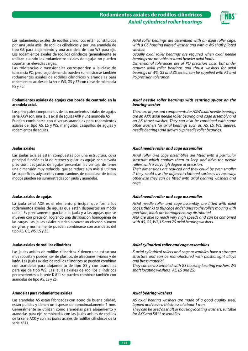
103
Rodamientos axiales de rodillos cilíndricosAxiall cylindrical roller bearings
Los rodamientos axiales de rodillos cilíndricos están constituídos por una jaula axial de rodillos cilíndricos y por una arandela de tipo GS para alojamiento y una arandela de tipo WS para eje. Los rodamientos axiales de rodillos cilíndricos generalmente se utilizan cuando los rodamientos axiales de agujas no pueden soportar las elevadas cargas.Las tolerancias dimensionales corresponden a la clase de tolerancia PO, pero bajo demanda pueden suministrarse también rodamientos axiales de rodillos cilíndricos y arandelas para rodamientos axiales de la serie WS, GS y ZS con clase de tolerancia P5 y P6.
Rodamientos axiales de agujas con borde de centrado en la arandela axial.
Los principales componentes de los rodamientos axiales de agujas serie AXW son: una jaula axial de agujas AXK y una arandela AS.Pueden combinarse con diversas arandelas para rodamientos axiales del tipo AS, LS y WS, manguitos, casquillos de agujas y rodamientos de agujas.
Jaulas axiales
Las jaulas axiales están compuestas por una estructura, cuya principal función es la de retener y guiar las agujas con elevada precisión. Las jaulas de agujas presentan las ventaja de tener una dimensión muy reducida, que se reduce aún más si utilizan las superficies adyacentes como caminos de rodadura; de todos modos pueden ser suministradas con jaula y arandelas.
Jaulas axiales de agujas
La jaula axial AXK es el elemento principal que forma los rodamientos axiales de agujas que están dispuestos en modo radial. Es precisamente gracias a la jaula y a las agujas que se mueven con precisión, logrando una distribución homogénea de las cargas. Las jaulas axiales pueden alcanzar un elevado número de giros y normalmente pueden combinarse con arandelas del tipo AS, GS, WS, LS y ZS.
Jaulas axiales de rodillos cilíndricos
Las jaulas axiales de rodillos cilíndricos K tienen una estructura muy robusta y pueden ser de plástico, de aleaciones livianas y de latón. Las jaulas axiales de rodillos cilíndricos se pueden combinar con arandelas para alojamiento de tipo GS y con arandelas para eje de tipo WS. Las jaulas axiales de rodillos cilíndricos pertenecientes a la serie K 811 se pueden combinar también con arandelas de tipo AS, LS y ZS.
Arandelas para rodamientos axiales
Las arandelas AS están fabricadas con acero de buena calidad, están pulidas y tienen un espesor de aproximadamente 1 mm. Generalmente se utilizan como arandelas para alojamiento y arandelas para eje, combinadas con las jaulas axiales de rodillos de la serie AXK y con las jaulas axiales de rodillos cilíndricos de la serie K811.
Axial roller bearings are assembled with an axial roller cage, with a GS housing piloted washer and with a WS shaft piloted washer.Usually axial roller bearings are required when axial needle bearings are not able to stand heavier axial loads.Dimensional tolerances are of PO precision class, but under request axial roller bearings and thrust washers for axial bearings of WS, GS and ZS series, can be supplied with P5 and P6 precision tolerance.
Axial needle roller bearings with centring spigot on the bearing washer
The most important components for AXW axial needle bearings are an AXK axial needle roller bearing and cage assembly and an AS thrust washer. They can also be combined with some other washers for axial bearings such as, AS, LS, WS, sleeves, needle bearings and drawn cup needle roller bearings.
Axial needle roller and cage assemblies
Axial roller and cage assemblies are fitted with a particular structure which enables them to keep and drive the needle rollers with a very high degree of precision.Their dimensions are reduced and they could be even smaller if they could use the adjacent cluttered surfaces as raceway, otherwise they can be fitted with axial bearing washers and cage.
Axial needle roller and cage assemblies
Axial needle roller and cage assembly, are fitted with axial cages: thanks to this cage and thanks to the rollers moving with precision, loads are homogeneously distributed. AXK are able to reach very high speeds and can be combined with AS, GS, WS, LS and ZS axial bearing washers.
Axial cylindrical roller and cage assemblies
K axial cylindrical rollers and cage assemblies have a stronger structure and can be manufactured with plastic, light alloys and brass material.They can be asssembled with GS housing locating washers WS shaft locating washers, AS, LS and ZS.
Axial bearing washers
AS axial bearing washers are made of a good quality steel, lapped and have a thickness of about 1 mm.They can be used as shaft or housing locating washers, suitable for AXK and K811 assemblies.
104
Rodamientos axiales de rodillos cilíndricosAxiall cylindrical roller bearings
Arandelas para alojamiento y para eje
Las arandelas pertenecientes a este grupo (GS y WS) son arandelas de tipo macizo, fabricadas con acero para rodamientos. Las superficies de rodamiento están pulidas, mientras que las superficies exteriores de la arandela para alojamiento están rectificadas.
Arandelas para rodamientos axiales
Las arandelas de tipo LS pertenecen a la línea más económica y se utilizan cuando no se requiere una elevada precisión. Se pueden emplear como arandelas para alojamiento y también como arandelas para eje.Los caminos rodantes de las arandelas están rectificados y se pueden combinar con las jaulas axiales de agujas de la serie AXK y de rodillos cilíndricos de la serie K 811.
Arandelas intermedias
Las arandelas de tipo intermedio ZSI y ZSE son ideales para obtener combinaciones de rodamientos axiales de doble efecto, con la utilización de arandelas de alojamiento GS y arandelas para eje WS. Se pueden montar entre dos jaulas de agujas de tipo AXK o de rodillos cilíndricos de la serie K 811.
Housing and shaft locating washers
These kinds of washers are made of hardened rolling bearing steel, GS and WS belong to a massive washers.Running surfaces are lapped, outer surfaces of housing washers are grinded.
Axial bearing washers
LS axial bearing washers belong to the most economical line as they are usually mounted when high precision is not required; they can be used as housing washers or as shaft washers.LS axial bearing washers have grinded raceways that can be combined with AXK Axial thrust needle roller and cage assemblies and with K 811 axial cylindrical roller and cage assemblies.
Intermediate washers
ZSI and ZSE intermediate washers are the most indicated double effect axial bearing by using housing (GS) and shaft (WS) locating washers. They can be mounted with two AXK axial needle roller and cage assemblies or with K 811 axial cylindrical roller and cage assemblies.
105
Tipo-Type Características-Characteristics
AS Arandela axial, utilizable como arandela para eje y para alojamiento, idónea para AXK y K 811 Axial bearings washer, used as a housing and shaft locating washer, suitable for AXK and K 811
GS Arandela para alojamiento, centrado exterior Housing locating washer, with outer centering
WS Arandela para eje, centrado interior Shaft locating washer, with inner centering
LS Arandela axial, utilizable como arandela para eje y para alojamiento, idónea para AXK y K 811 (menor precisión) Axial bearing washer, used as a shaft and housing locating washer, suitable for AXK and K 811 (lower precision)
ZSI - ZSE Arandela intermedia con centrado interior y exterior, utilizable combinada con rodamientos axiales de doble efecto, idónea para AXK y K811
Intermediate washer with inner and outer centering, can be used if combined with double effect axial bearings, suitable for AXK and K811
Tipologías de los rodamientos axiales de agujas y de rodillos cilíndricosAxial needle and cylindrical roller bearings types
Tipo-Type Características-Characteristics
AxW Rodamiento axial de agujas, formado por AXK y AS con borde de centrado, combinable con diversos tipos de arandelas para rodamientos axiales, manguitos, casquillos y rodamientos de agujas.
Axial needle bearings, composed by AXK and AS with centering spigot, can be combined with different types of axial bearing washers, bushes, drawn cups and needle bearings.
811-812 Rodamientos axiales de rodillos cilíndricos, formados por K 811 o 812 con GS o WS (idóneos para cargas axiales elevadas)
Axial cylindrical roller bearings, composed by K 811 or 812 with GS or WS (suitable for high axial loads)
893-894 Rodamientos axiales de rodillos cilíndricos, formados por K 893 o 894 con GS o WS (idóneos para cargas axiales muy elevadas)
Axial cylindrical roller bearings, composed by K 893 or 894 with GS or WS (suitable for the highest axial loads)
Tipologías de arandelas para rodamientos axialesAxial bearings washers type
Tipologías de las jaulas axiales de agujas y de rodillos cilíndricosAxial needle cylindrical roller and cage assemblies types
Tipo-Type Características-Characteristics
AxK Jaula axial de agujas, combinable con diversas tipologías de arandelas para rodamientos axiales. Axial needle roller and cage assembly, that can be combined with different types of axial bearing washers.
K 811-812 Jaulas axiales de rodillos cilíndricos, de una hilera, combinables con diversas tipologías de arandelas para rodamientos axiales.
Axial cylindrical roller and cage assemblies with one crown, that can be combined with different types of axial bearing washers.
K 893-894 Jaulas axiales de rodillos cilíndricos, de dos hileras, combinables con diversas arandelas para rodamientos axiales.
Axial cylindrical roller and cage assemblies with two crowns, that can be combined with different axial bearing washers.
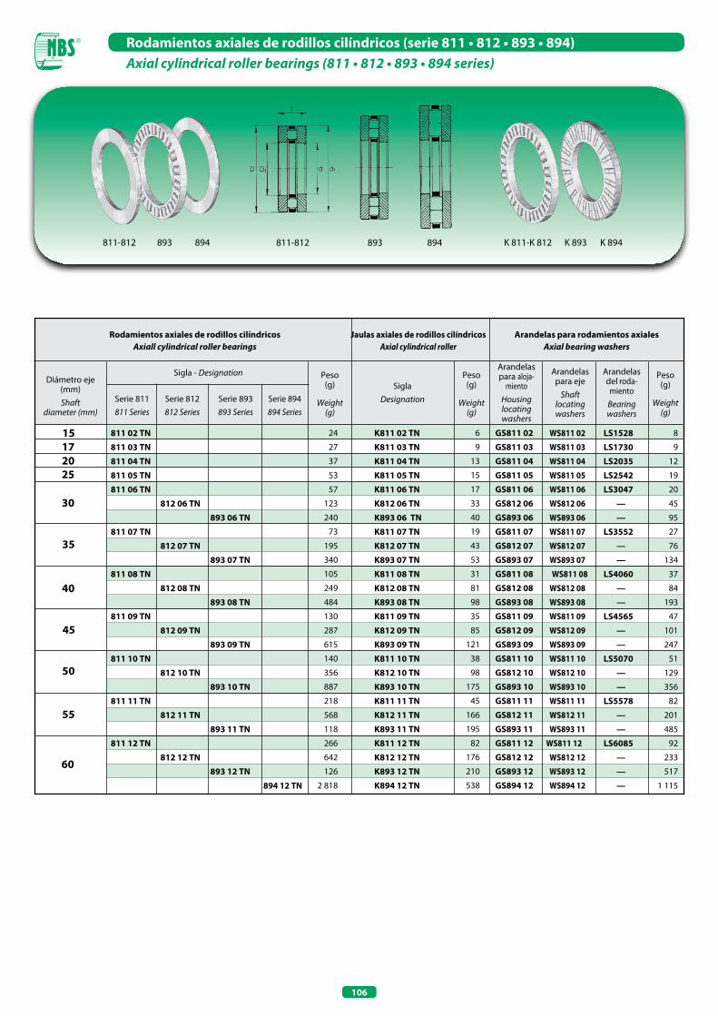
106
Rodamientos axiales de rodillos cilíndricos (serie 811 • 812 • 893 • 894)Axial cylindrical roller bearings (811 • 812 • 893 • 894 series)
811-812 893 894811-812 893 894 K 811-K 812 K 893 K 894
Arandelas para rodamientos axialesAxial bearing washers
Diámetro eje (mm) Shaft
diameter (mm)
Sigla - Designation Peso(g)
Weight(g)
Peso(g)
Weight(g)
Peso(g)
Weight(g)
SiglaDesignation
Arandelas para aloja-
mientoHousinglocatingwashers
Arandelas del roda-
mientoBearingwashers
Arandelas para eje
Shaftlocatingwashers
15 17 20
35
40
60
811 02 TN
811 03 TN
811 04 TN
811 05 TN
811 06 TN
812 06 TN
893 06 TN
811 07 TN
812 07 TN
893 07 TN
811 08 TN
812 08 TN
893 08 TN
811 09 TN
812 09 TN
893 09 TN
811 10 TN
812 10 TN
893 10 TN
811 11 TN
812 11 TN
893 11 TN
811 12 TN
812 12 TN
893 12 TN
894 12 TN
K811 02 TN
K811 03 TN
K811 04 TN
K811 05 TN
K811 06 TN
K812 06 TN
K893 06 TN
K811 07 TN
K812 07 TN
K893 07 TN
K811 08 TN
K812 08 TN
K893 08 TN
K811 09 TN
K812 09 TN
K893 09 TN
K811 10 TN
K812 10 TN
K893 10 TN
K811 11 TN
K812 11 TN
K893 11 TN
K811 12 TN
K812 12 TN
K893 12 TN
K894 12 TN
GS811 02
GS811 03
GS811 04
GS811 05
GS811 06
GS812 06
GS893 06
GS811 07
GS812 07
GS893 07
GS811 08
GS812 08
GS893 08
GS811 09
GS812 09
GS893 09
GS811 10
GS812 10
GS893 10
GS811 11
GS812 11
GS893 11
GS811 12
GS812 12
GS893 12
GS894 12
24
27
37
53
57
123
240
73
195
340
105
249
484
130
287
615
140
356
887
218
568
118
266
642
126
2 818
6
9
13
15
17
33
40
19
43
53
31
81
98
35
85
121
38
98
175
45
166
195
82
176
210
538
25
30
45
50
55
Jaulas axiales de rodillos cilíndricosAxial cylindrical roller
Rodamientos axiales de rodillos cilíndricosAxiall cylindrical roller bearings
LS1528
LS1730
LS2035
LS2542
LS3047
—
—
LS3552
—
—
LS4060
—
—
LS4565
—
—
LS5070
—
—
LS5578
—
—
LS6085
—
—
—
8
9
12
19
20
45
95
27
76
134
37
84
193
47
101
247
51
129
356
82
201
485
92
233
517
1 115
WS811 02
WS811 03
WS811 04
WS811 05
WS811 06
WS812 06
WS893 06
WS811 07
WS812 07
WS893 07
WS811 08
WS812 08
WS893 08
WS811 09
WS812 09
WS893 09
WS811 10
WS812 10
WS893 10
WS811 11
WS812 11
WS893 11
WS811 12
WS812 12
WS893 12
WS894 12
Serie 811811 Series
Serie 812812 Series
Serie 893893 Series
Serie 894894 Series
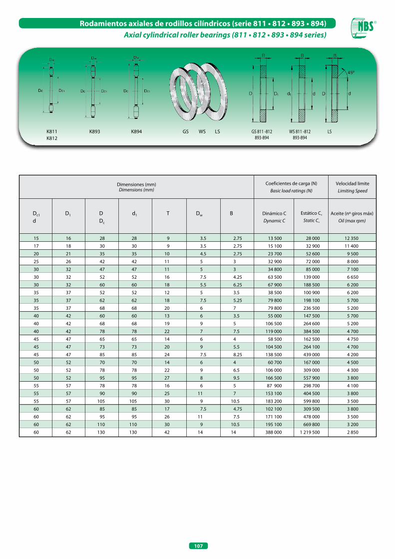
107
Rodamientos axiales de rodillos cilíndricos (serie 811 • 812 • 893 • 894)Axial cylindrical roller bearings (811 • 812 • 893 • 894 series)
K893K811K812
K894 GS 811 -812893-894
WS 811 -812893-894
LSGS LSWS
Velocidad limiteLimiting Speed
Dimensiones (mm)Dimensions (mm)
Coeficientes de carga (N)Basic load ratings (N)
Dinámico CDynamic C
Estático Co
Static Co
Aceite (nº giros máx)Oil (max rpm)
15 16 28 28 9 3.5 2.75
17 18 30 30 9 3.5 2.75
20 21 35 35 10 4.5 2.75
25 26 42 42 11 5 3
30 32 47 47 11 5 3
30 32 52 52 16 7.5 4.25
30 32 60 60 18 5.5 6.25
35 37 52 52 12 5 3.5
35 37 62 62 18 7.5 5.25
35 37 68 68 20 6 7
40 42 60 60 13 6 3.5
40 42 68 68 19 9 5
40 42 78 78 22 7 7.5
45 47 65 65 14 6 4
45 47 73 73 20 9 5.5
45 47 85 85 24 7.5 8.25
50 52 70 70 14 6 4
50 52 78 78 22 9 6.5
50 52 95 95 27 8 9.5
55 57 78 78 16 6 5
55 57 90 90 25 11 7
55 57 105 105 30 9 10.5
60 62 85 85 17 7.5 4.75
60 62 95 95 26 11 7.5
60 62 110 110 30 9 10.5
60 62 130 130 42 14 14
Dc1 D1 D d1 T Dw B d Dc
13 500 28 000 12 350
15 100 32 900 11 400
23 700 52 600 9 500
32 900 72 000 8 000
34 800 85 000 7 100
63 500 139 000 6 650
67 900 188 500 6 200
38 500 100 900 6 200
79 800 198 100 5 700
79 800 236 500 5 200
55 000 147 500 5 700
106 500 264 600 5 200
119 000 384 500 4 700
58 500 162 500 4 750
104 500 264 100 4 700
138 500 439 000 4 200
60 700 167 000 4 500
106 000 309 000 4 300
166 500 557 900 3 800
87 900 298 700 4 100
153 100 404 500 3 800
183 200 599 800 3 500
102 100 309 500 3 800
171 100 478 000 3 500
195 100 669 800 3 200
388 000 1 219 500 2 850
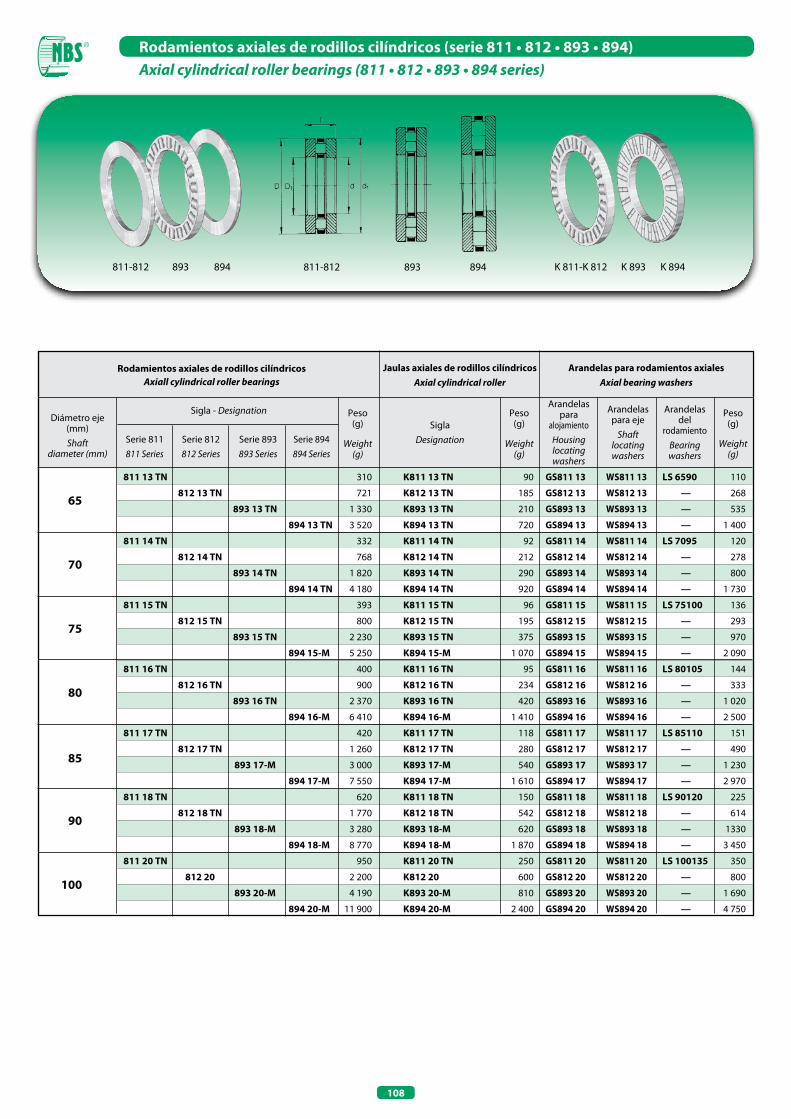
108
Rodamientos axiales de rodillos cilíndricos (serie 811 • 812 • 893 • 894)Axial cylindrical roller bearings (811 • 812 • 893 • 894 series)
Arandelas para rodamientos axialesAxial bearing washers
Diámetro eje (mm) Shaft
diameter (mm)
65
70
75
80
85
90
100
811 13 TN
812 13 TN
893 13 TN
894 13 TN
811 14 TN
812 14 TN
893 14 TN
894 14 TN
811 15 TN
812 15 TN
893 15 TN
894 15-M
811 16 TN
812 16 TN
893 16 TN
894 16-M
811 17 TN
812 17 TN
893 17-M
894 17-M
811 18 TN
812 18 TN
893 18-M
894 18-M
811 20 TN
812 20
893 20-M
894 20-M
K811 13 TN
K812 13 TN
K893 13 TN
K894 13 TN
K811 14 TN
K812 14 TN
K893 14 TN
K894 14 TN
K811 15 TN
K812 15 TN
K893 15 TN
K894 15-M
K811 16 TN
K812 16 TN
K893 16 TN
K894 16-M
K811 17 TN
K812 17 TN
K893 17-M
K894 17-M
K811 18 TN
K812 18 TN
K893 18-M
K894 18-M
K811 20 TN
K812 20
K893 20-M
K894 20-M
GS811 13
GS812 13
GS893 13
GS894 13
GS811 14
GS812 14
GS893 14
GS894 14
GS811 15
GS812 15
GS893 15
GS894 15
GS811 16
GS812 16
GS893 16
GS894 16
GS811 17
GS812 17
GS893 17
GS894 17
GS811 18
GS812 18
GS893 18
GS894 18
GS811 20
GS812 20
GS893 20
GS894 20
310
721
1 330
3 520
332
768
1 820
4 180
393
800
2 230
5 250
400
900
2 370
6 410
420
1 260
3 000
7 550
620
1 770
3 280
8 770
950
2 200
4 190
11 900
90
185
210
720
92
212
290
920
96
195
375
1 070
95
234
420
1 410
118
280
540
1 610
150
542
620
1 870
250
600
810
2 400
LS 6590
—
—
—
LS 7095
—
—
—
LS 75100
—
—
—
LS 80105
—
—
—
LS 85110
—
—
—
LS 90120
—
—
—
LS 100135
—
—
—
WS811 13
WS812 13
WS893 13
WS894 13
WS811 14
WS812 14
WS893 14
WS894 14
WS811 15
WS812 15
WS893 15
WS894 15
WS811 16
WS812 16
WS893 16
WS894 16
WS811 17
WS812 17
WS893 17
WS894 17
WS811 18
WS812 18
WS893 18
WS894 18
WS811 20
WS812 20
WS893 20
WS894 20
Peso(g)
Weight(g)
Peso(g)
Weight(g)
Peso(g)
Weight(g)
SiglaDesignation
Arandelas para
alojamientoHousinglocatingwashers
Arandelas del
rodamientoBearingwashers
Arandelas para eje
Shaftlocatingwashers
Jaulas axiales de rodillos cilíndricosAxial cylindrical roller
Rodamientos axiales de rodillos cilíndricosAxiall cylindrical roller bearings
110
268
535
1 400
120
278
800
1 730
136
293
970
2 090
144
333
1 020
2 500
151
490
1 230
2 970
225
614
1330
3 450
350
800
1 690
4 750
Sigla - Designation
Serie 811811 Series
Serie 812812 Series
Serie 893893 Series
Serie 894894 Series
811-812 893 894811-812 893 894 K 811-K 812 K 893 K 894
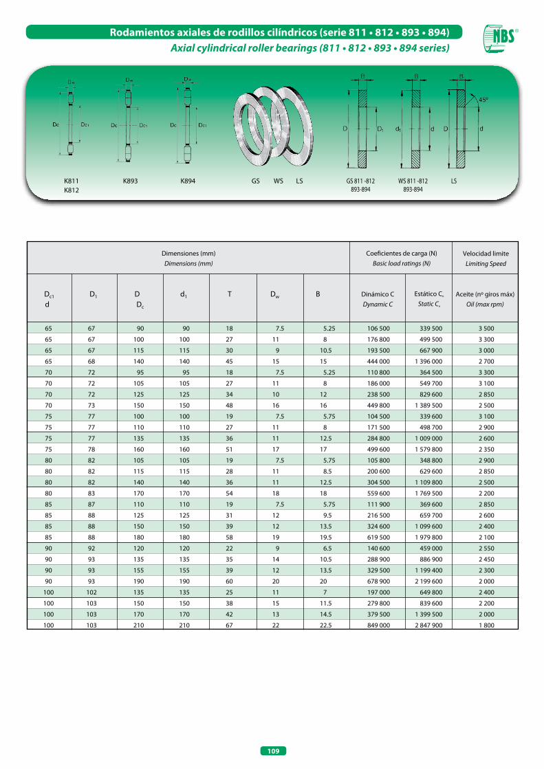
109
Rodamientos axiales de rodillos cilíndricos (serie 811 • 812 • 893 • 894)Axial cylindrical roller bearings (811 • 812 • 893 • 894 series)
Velocidad limiteLimiting Speed
Dimensiones (mm)Dimensions (mm)
Coeficientes de carga (N)Basic load ratings (N)
Dinámico CDynamic C
Estático Co
Static Co
Aceite (nº giros máx)Oil (max rpm)
65 67 90 90 18 7.5 5.25
65 67 100 100 27 11 8
65 67 115 115 30 9 10.5
65 68 140 140 45 15 15
70 72 95 95 18 7.5 5.25
70 72 105 105 27 11 8
70 72 125 125 34 10 12
70 73 150 150 48 16 16
75 77 100 100 19 7.5 5.75
75 77 110 110 27 11 8
75 77 135 135 36 11 12.5
75 78 160 160 51 17 17
80 82 105 105 19 7.5 5.75
80 82 115 115 28 11 8.5
80 82 140 140 36 11 12.5
80 83 170 170 54 18 18
85 87 110 110 19 7.5 5.75
85 88 125 125 31 12 9.5
85 88 150 150 39 12 13.5
85 88 180 180 58 19 19.5
90 92 120 120 22 9 6.5
90 93 135 135 35 14 10.5
90 93 155 155 39 12 13.5
90 93 190 190 60 20 20
100 102 135 135 25 11 7
100 103 150 150 38 15 11.5
100 103 170 170 42 13 14.5
100 103 210 210 67 22 22.5
Dc1 D1 D d1 T Dw B d Dc
106 500 339 500 3 500
176 800 499 500 3 300
193 500 667 900 3 000
444 000 1 396 000 2 700
110 800 364 500 3 300
186 000 549 700 3 100
238 500 829 600 2 850
449 800 1 389 500 2 500
104 500 339 600 3 100
171 500 498 700 2 900
284 800 1 009 000 2 600
499 600 1 579 800 2 350
105 800 348 800 2 900
200 600 629 600 2 850
304 500 1 109 800 2 500
559 600 1 769 500 2 200
111 900 369 600 2 850
216 500 659 700 2 600
324 600 1 099 600 2 400
619 500 1 979 800 2 100
140 600 459 000 2 550
288 900 886 900 2 450
329 500 1 199 400 2 300
678 900 2 199 600 2 000
197 000 649 800 2 400
279 800 839 600 2 200
379 500 1 399 500 2 000
849 000 2 847 900 1 800
K893K811K812
K894 GS 811 -812893-894
WS 811 -812893-894
LSGS LSWS

110
Rodamientos axiales de rodillos cilíndricos (serie 811 • 812 • 893 • 894)Axial cylindrical roller bearings (811 • 812 • 893 • 894 series)
Arandelas para rodamientos axialesAxial bearing washers
Diámetro eje (mm) Shaft
diameter (mm)
110
120
130
140
150
160
170
811 22 TN
812 22 TN
893 22 - M
894 22 - M
811 24 TN
812 24 TN
893 24 - M
894 24 - M
811 26 TN
812 26 TN
893 26 - M
894 26 - M
811 28 TN
812 28 - M
893 28 - M
894 28 - M
811 30 TN
812 30 - M
893 30 - M
894 30 - M
811 32 TN
812 32 - M
894 32 - M
811 34 TN
812 34 - M
894 34 - M
K811 22 TN
K812 22 TN
K893 22 - M
K894 22 - M
K811 24 TN
K812 24 TN
K893 24 - M
K894 24 - M
K811 26 TN
K812 26 TN
K893 26 - M
K894 26 - M
K811 28 TN
K812 28 - M
K893 28 - M
K894 28 - M
K811 30 TN
K812 30 TN
K893 30 - M
K894 30 - M
K811 32 TN
K812 32 - M
K894 32 - M
K811 34 TN
K812 34 - M
K894 34 - M
GS811 22
GS812 22
GS893 22
GS894 22
GS811 24
GS812 24
GS893 24
GS894 24
GS811 26
GS812 26
GS893 26
GS894 26
GS811 28
GS812 28
GS893 28
GS894 28
GS811 30
GS812 30
GS893 30
GS894 30
GS811 32
GS812 32
GS894 32
GS811 34
GS812 34
GS894 34
1 040
2 445
6 030
15 600
1 170
2 690
8 520
19 700
1 700
4 204
10 000
24 000
1 946
4 567
11 990
27 200
2 066
5 886
12 630
32 100
2 189
6 203
38 200
2 950
7 690
47 200
270
685
1 150
3 300
340
730
1 720
4 300
414
1 144
1 910
5 000
448
1 197
2 390
6 000
474
1 520
2 510
7 100
505
1 603
8 600
750
1 890
10 200
LS 110145
—
—
—
LS 120155
—
—
—
LS 130170
—
—
—
LS 140180
—
—
—
LS 150190
—
—
—
LS 160200
—
—
—
—
—
385
880
2 440
6 150
415
980
3 400
7 700
643
1 530
4 045
9 500
749
1 635
4 800
10 600
796
2 180
5 060
12 500
842
2 300
14 800
1 100
2 900
18 500
WS811 22
WS812 22
WS893 22
WS894 22
WS811 24
WS812 24
WS893 24
WS894 24
WS811 26
WS812 26
WS893 26
WS894 26
WS811 28
WS812 28
WS893 28
WS894 28
WS811 30
WS812 30
WS893 30
WS894 30
WS811 32
WS812 32
WS894 32
WS811 34
WS812 34
WS894 34
Peso(g)
Weight(g)
Peso(g)
Weight(g)
Peso(g)
Weight(g)
SiglaDesignation
Arandelas para aloja-
mientoHousinglocatingwashers
Arandelas del roda-
mientoBearingwashers
Arandelas para eje
Shaftlocatingwashers
Jaulas axiales de rodillos cilíndricosAxial cylindrical roller
Rodamientos axiales de rodillos cilíndricosAxiall cylindrical roller bearings
Sigla - Designation
Serie 811811 Series
Serie 812812 Series
Serie 893893 Series
Serie 894894 Series
811-812 893 894811-812 893 894 K 811-K 812 K 893 K 894
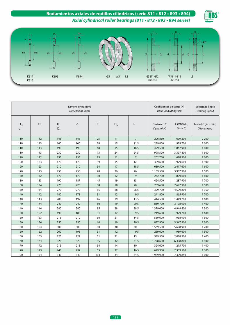
111
Rodamientos axiales de rodillos cilíndricos (serie 811 • 812 • 893 • 894)Axial cylindrical roller bearings (811 • 812 • 893 • 894 series)
Velocidad limiteLimiting Speed
Dimensiones (mm)Dimensions (mm)
Coeficientes de carga (N)Basic load ratings (N)
Dinámico CDynamic C
Estático Co
Static Co
Aceite (nº giros máx)Oil (max rpm)
110 112 145 145 25 11 7
110 113 160 160 38 15 11.5
110 113 190 190 48 15 16.5
110 113 230 230 73 24 24.5
120 122 155 155 25 11 7
120 123 170 170 39 15 12
120 123 210 210 54 17 18.5
120 123 250 250 78 26 26
130 132 170 170 30 12 9
130 133 190 187 45 19 13
130 134 225 225 58 18 20
130 134 270 270 85 28 28.5
140 142 180 178 31 12 9.5
140 143 200 197 46 19 13.5
140 144 240 240 60 19 20.5
140 144 280 280 85 28 28.5
150 152 190 188 31 12 9.5
150 153 215 212 50 21 14.5
150 154 250 250 60 19 20.5
150 154 300 300 90 30 30
160 162 200 198 31 12 9.5
160 163 225 222 51 21 15
160 164 320 320 95 32 31.5
170 172 215 213 34 14 10
170 173 240 237 55 22 16.5
170 174 340 340 103 34 34.5
Dc1 D1 D d1 T Dw B d Dc
206 850 699 200 2 200
299 800 939 700 2 000
499 500 1 867 900 1 800
998 500 3 397 800 1 600
202 700 698 900 2 000
309 600 979 600 1 900
639 500 2 417 600 1 600
1 159 500 3 987 900 1 500
232 700 809 600 1 800
424 500 1 287 900 1 700
709 600 2 697 900 1 500
1 329 700 4 599 800 1 350
241 800 865 900 1 700
444 500 1 449 700 1 600
819 700 3 198 900 1 400
1 379 600 4 949 800 1 300
249 600 929 700 1 600
589 600 1 938 900 1 500
837 900 3 347 900 1 300
1 569 500 5 698 900 1 200
259 600 989 600 1 500
599 500 2 028 900 1 400
1 778 600 6 498 800 1 100
324 600 1 215 700 1 400
679 900 2 339 500 1 300
1 989 900 7 399 850 1 000
K893K811K812
K894 GS 811 -812893-894
WS 811 -812893-894
LSGS LSWS
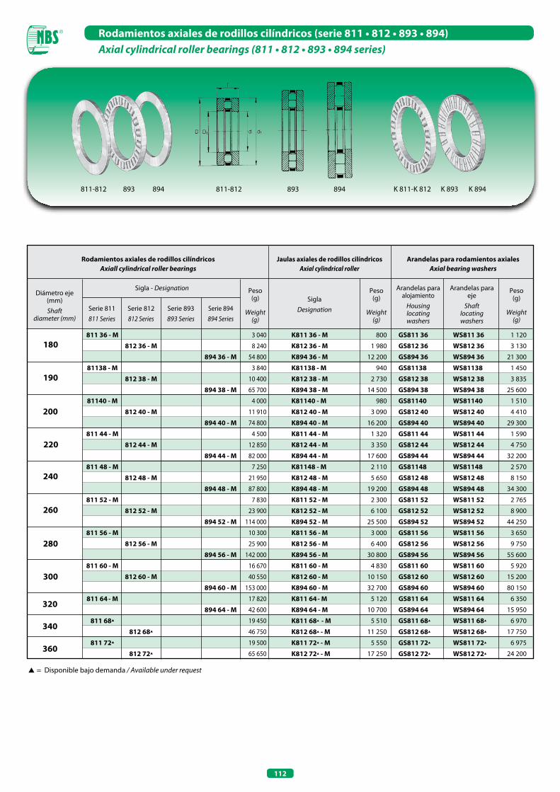
112
Rodamientos axiales de rodillos cilíndricos (serie 811 • 812 • 893 • 894)Axial cylindrical roller bearings (811 • 812 • 893 • 894 series)
s= Disponible bajo demanda / Available under request
Arandelas para rodamientos axialesAxial bearing washers
Diámetro eje (mm) Shaft
diameter (mm)
180
190
200
320
340
360
811 36 - M
812 36 - M
894 36 - M
81138 - M
812 38 - M
894 38 - M
81140 - M
812 40 - M
894 40 - M
811 44 - M
812 44 - M
894 44 - M
811 48 - M
812 48 - M
894 48 - M
811 52 - M
812 52 - M
894 52 - M
811 56 - M
812 56 - M
894 56 - M
811 60 - M
812 60 - M
894 60 - M
811 64- M
894 64 - M
811 68s
812 68s
811 72s
812 72s
K811 36 - M
K812 36 - M
K894 36 - M
K81138 - M
K812 38 - M
K894 38 - M
K81140 - M
K812 40 - M
K894 40 - M
K811 44 - M
K812 44 - M
K894 44 - M
K81148 - M
K812 48 - M
K894 48 - M
K811 52 - M
K812 52 - M
K894 52 - M
K811 56 - M
K812 56 - M
K894 56 - M
K811 60 - M
K812 60 - M
K894 60 - M
K811 64- M
K894 64 - M
K811 68s - M
K812 68s - M
K811 72s - M
K812 72s - M
GS811 36
GS812 36
GS894 36
GS81138
GS812 38
GS894 38
GS81140
GS812 40
GS894 40
GS811 44
GS812 44
GS894 44
GS81148
GS812 48
GS894 48
GS811 52
GS812 52
GS894 52
GS811 56
GS812 56
GS894 56
GS811 60
GS812 60
GS894 60
GS811 64
GS894 64
GS811 68s
GS812 68s
GS811 72s
GS812 72s
WS811 36
WS812 36
WS894 36
WS81138
WS812 38
WS894 38
WS81140
WS812 40
WS894 40
WS811 44
WS812 44
WS894 44
WS81148
WS812 48
WS894 48
WS811 52
WS812 52
WS894 52
WS811 56
WS812 56
WS894 56
WS811 60
WS812 60
WS894 60
WS811 64
WS894 64
WS811 68s
WS812 68s
WS811 72s
WS812 72s
3 040
8 240
54 800
3 840
10 400
65 700
4 000
11 910
74 800
4 500
12 850
82 000
7 250
21 950
87 800
7 830
23 900
114 000
10 300
25 900
142 000
16 670
40 550
153 000
17 820
42 600
19 450
46 750
19 500
65 650
800
1 980
12 200
940
2 730
14 500
980
3 090
16 200
1 320
3 350
17 600
2 110
5 650
19 200
2 300
6 100
25 500
3 000
6 400
30 800
4 830
10 150
32 700
5 120
10 700
5 510
11 250
5 550
17 250
220
240
260
280
300
1 120
3 130
21 300
1 450
3 835
25 600
1 510
4 410
29 300
1 590
4 750
32 200
2 570
8 150
34 300
2 765
8 900
44 250
3 650
9 750
55 600
5 920
15 200
80 150
6 350
15 950
6 970
17 750
6 975
24 200
Peso(g)
Weight(g)
Peso(g)
Weight(g)
Peso(g)
Weight(g)
SiglaDesignation
Arandelas para alojamiento
Housinglocatingwashers
Arandelas para eje
Shaftlocatingwashers
Jaulas axiales de rodillos cilíndricosAxial cylindrical roller
Rodamientos axiales de rodillos cilíndricosAxiall cylindrical roller bearings
Sigla - Designation
Serie 811811 Series
Serie 812812 Series
Serie 893893 Series
Serie 894894 Series
811-812 893 894811-812 893 894 K 811-K 812 K 893 K 894
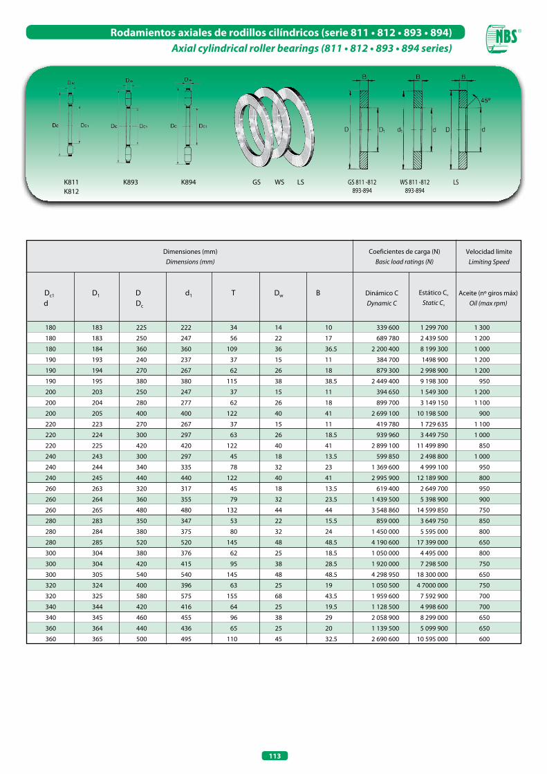
113
Rodamientos axiales de rodillos cilíndricos (serie 811 • 812 • 893 • 894)Axial cylindrical roller bearings (811 • 812 • 893 • 894 series)
Velocidad limiteLimiting Speed
Dimensiones (mm)Dimensions (mm)
Coeficientes de carga (N)Basic load ratings (N)
Dinámico CDynamic C
Estático Co
Static Co
Aceite (nº giros máx)Oil (max rpm)
180 183 225 222 34 14 10
180 183 250 247 56 22 17
180 184 360 360 109 36 36.5
190 193 240 237 37 15 11
190 194 270 267 62 26 18
190 195 380 380 115 38 38.5
200 203 250 247 37 15 11
200 204 280 277 62 26 18
200 205 400 400 122 40 41
220 223 270 267 37 15 11
220 224 300 297 63 26 18.5
220 225 420 420 122 40 41
240 243 300 297 45 18 13.5
240 244 340 335 78 32 23
240 245 440 440 122 40 41
260 263 320 317 45 18 13.5
260 264 360 355 79 32 23.5
260 265 480 480 132 44 44
280 283 350 347 53 22 15.5
280 284 380 375 80 32 24
280 285 520 520 145 48 48.5
300 304 380 376 62 25 18.5
300 304 420 415 95 38 28.5
300 305 540 540 145 48 48.5
320 324 400 396 63 25 19
320 325 580 575 155 68 43.5
340 344 420 416 64 25 19.5
340 345 460 455 96 38 29
360 364 440 436 65 25 20
360 365 500 495 110 45 32.5
Dc1 D1 D d1 T Dw B d Dc
339 600 1 299 700 1 300
689 780 2 439 500 1 200
2 200 400 8 199 300 1 000
384 700 1498 900 1 200
879 300 2 998 900 1 200
2 449 400 9 198 300 950
394 650 1 549 300 1 200
899 700 3 149 150 1 100
2 699 100 10 198 500 900
419 780 1 729 635 1 100
939 960 3 449 750 1 000
2 899 100 11 499 890 850
599 850 2 498 800 1 000
1 369 600 4 999 100 950
2 995 900 12 189 900 800
619 400 2 649 700 950
1 439 500 5 398 900 900
3 548 860 14 599 850 750
859 000 3 649 750 850
1 450 000 5 595 000 800
4 190 600 17 399 000 650
1 050 000 4 495 000 800
1 920 000 7 298 500 750
4 298 950 18 300 000 650
1 050 500 4 7000 000 750
1 959 600 7 592 900 700
1 128 500 4 998 600 700
2 058 900 8 299 000 650
1 139 500 5 099 900 650
2 690 600 10 595 000 600
K893K811K812
K894 GS 811 -812893-894
WS 811 -812893-894
LSGS LSWS
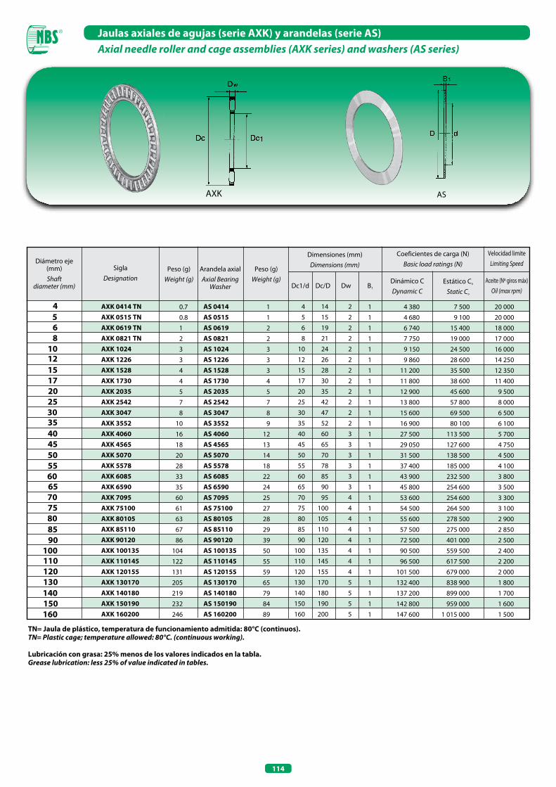
114
Jaulas axiales de agujas (serie AxK) y arandelas (serie AS) Axial needle roller and cage assemblies (AXK series) and washers (AS series)
TN= Jaula de plástico, temperatura de funcionamiento admitida: 80°C (continuos).TN= Plastic cage; temperature allowed: 80°C. (continuous working).
4
Diámetro eje (mm) Shaft
diameter (mm)
Dimensiones (mm)Dimensions (mm)
Coeficientes de carga (N)Basic load ratings (N)
Dc/DDc1/d
6
AxK 0414 TNAxK 0515 TNAxK 0619 TNAxK 0821 TNAxK 1024AxK 1226AxK 1528AxK 1730AxK 2035AxK 2542AxK 3047AxK 3552AxK 4060AxK 4565AxK 5070AxK 5578AxK 6085AxK 6590AxK 7095AxK 75100AxK 80105AxK 85110AxK 90120AxK 100135AxK 110145AxK 120155AxK 130170AxK 140180AxK 150190AxK 160200
0.7
0.8
1
2
3
3
4
4
5
7
8
10
16
18
20
28
33
35
60
61
63
67
86
104
122
131
205
219
232
246
1
1
1
1
1
1
1
1
1
1
1
1
1
1
1
1
1
1
1
1
1
1
1
1
1
1
1
1
1
1
4 14 2
5 15 2
6 19 2
8 21 2
10 24 2
12 26 2
15 28 2
17 30 2
20 35 2
25 42 2
30 47 2
35 52 2
40 60 3
45 65 3
50 70 3
55 78 3
60 85 3
65 90 3
70 95 4
75 100 4
80 105 4
85 110 4
90 120 4
100 135 4
110 145 4
120 155 4
130 170 5
140 180 5
150 190 5
160 200 5
5
8
35
Aceite (Nº giros máx)Oil (max rpm)
SiglaDesignation
Dw B1
10 12 15 17 20 25 30
Dinámico CDynamic C
Estático Co
Static Co
40 45 50 55 60 65 70 75 80 85 90 100 110 120 130 140 150 160
Peso (g)Weight (g)
Peso (g)Weight (g)
Arandela axialAxial Bearing
Washer
Velocidad limiteLimiting Speed
Lubricación con grasa: 25% menos de los valores indicados en la tabla.Grease lubrication: less 25% of value indicated in tables.
AXK AS
AS 0414AS 0515AS 0619AS 0821AS 1024AS 1226AS 1528AS 1730AS 2035AS 2542AS 3047AS 3552AS 4060AS 4565AS 5070AS 5578AS 6085AS 6590AS 7095AS 75100AS 80105AS 85110AS 90120AS 100135AS 110145AS 120155AS 130170AS 140180AS 150190AS 160200
1
1
2
2
3
3
3
4
5
7
8
9
12
13
14
18
22
24
25
27
28
29
39
50
55
59
65
79
84
89
4 380 7 500 20 000
4 680 9 100 20 000
6 740 15 400 18 000
7 750 19 000 17 000
9 150 24 500 16 000
9 860 28 600 14 250
11 200 35 500 12 350
11 800 38 600 11 400
12 900 45 600 9 500
13 800 57 800 8 000
15 600 69 500 6 500
16 900 80 100 6 100
27 500 113 500 5 700
29 050 127 600 4 750
31 500 138 500 4 500
37 400 185 000 4 100
43 900 232 500 3 800
45 800 254 600 3 500
53 600 254 600 3 300
54 500 264 500 3 100
55 600 278 500 2 900
57 500 275 000 2 850
72 500 401 000 2 500
90 500 559 500 2 400
96 500 617 500 2 200
101 500 679 000 2 000
132 400 838 900 1 800
137 200 899 000 1 700
142 800 959 000 1 600
147 600 1 015 000 1 500
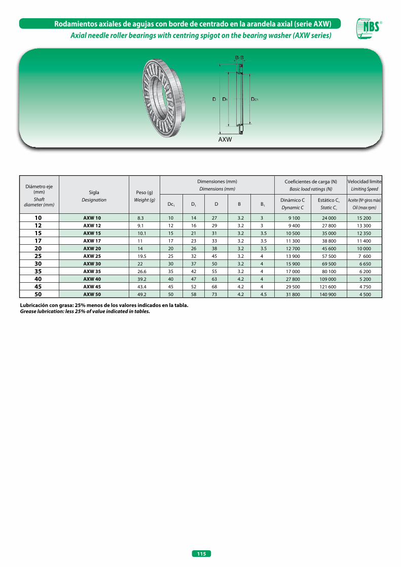
115
Rodamientos axiales de agujas con borde de centrado en la arandela axial (serie AxW)Axial needle roller bearings with centring spigot on the bearing washer (AXW series)
Lubricación con grasa: 25% menos de los valores indicados en la tabla.Grease lubrication: less 25% of value indicated in tables.
Diámetro eje (mm) Shaft
diameter (mm)
SiglaDesignation
Peso (g)Weight (g)
Dimensiones (mm)Dimensions (mm)
Coeficientes de carga (N)Basic load ratings (N)
Dinámico CDynamic C
Estático Co
Static Co
Dc1 D1 D
10 12 15 17 20 25 30 35 40 45 50
AxW 10 AxW 12 AxW 15 AxW 17 AxW 20 AxW 25 AxW 30 AxW 35 AxW 40 AxW 45 AxW 50
8.3
9.1
10.1
11
14
19.5
22
26.6
39.2
43.4
49.2
10 14 27 3.2 3
12 16 29 3.2 3
15 21 31 3.2 3.5
17 23 33 3.2 3.5
20 26 38 3.2 3.5
25 32 45 3.2 4
30 37 50 3.2 4
35 42 55 3.2 4
40 47 63 4.2 4
45 52 68 4.2 4
50 58 73 4.2 4.5
9 100 24 000 15 200
9 400 27 800 13 300
10 500 35 000 12 350
11 300 38 800 11 400
12 700 45 600 10 000
13 900 57 500 7 600
15 900 69 500 6 650
17 000 80 100 6 200
27 800 109 000 5 200
29 500 121 600 4 750
31 800 140 900 4 500
Aceite (Nº giros máx)Oil (max rpm)
Velocidad limiteLimiting Speed
B B1
AXW

116
Arandelas intermedias con centrado interior (serie ZSI)Intermediate washers with inner centering (ZSI series)
ZSI
Diámetro Eje (mm) Shaft
Diameter (mm)
SiglaDesignation
Peso (g)Weight (g)
Dimensiones (mm)Dimensions (mm)
d D B
15 17 20 25 30 35 40 45 50 55 60 65 70 75 80 85 90 100 110 120 130 140 150 160
ZSI 1127
ZSI 1329
ZSI 1634
ZSI 2141
ZSI 2646
ZSI 3151
ZSI 3159
ZSI 3664
ZSI 4169
ZSI 4677
ZSI 5184
ZSI 5689
ZSI 5694
ZSI 6199
ZSI 66104
ZSI 71109
ZSI 76119
ZSI 86134
ZSI 96144
ZSI 101154
ZSI 111169
ZSI 121179
ZSI 131189
ZSI 141199
21
23
31
45
60
78
125
156
191
235
316
360
440
470
500
593
806
1 180
1 430
1 830
2 210
2 460
2 740
3 030
11 27 5.5
13 29 5.5
16 34 5.5
21 41 6
26 46 7
31 51 8
31 59 8
36 64 9
41 69 10
46 77 10
51 84 11.5
56 89 12
56 94 12.5
61 99 12.5
66 104 12.5
71 109 14.5
76 119 16
86 134 18
96 144 20
101 154 22
111 169 22
121 179 23
131 189 24
141 199 25
AxK 1528 K 811 02 TN GS 811 02
AxK 1730 K 811 03 TN GS 811 03
AxK 2035 K 811 04 TN GS 811 04
AxK 2542 K 811 05 TN GS 811 05
AxK 3047 K 811 06 TN GS 811 06
AxK 3552 K 811 07 TN GS 811 07
AxK 4060 K 811 08 TN GS 811 08
AxK 4565 K 811 09 TN GS 811 09
AxK 5070 K 811 10 TN GS 811 10
AxK 5578 K 811 11 TN GS 811 11
AxK 6085 K 811 12 TN GS 811 12
AxK 6590 K 811 13 TN GS 811 13
AxK 7095 K 811 14 TN GS 811 14
AxK 75100 K 811 15 TN GS 811 15
AxK 80105 K 811 16 TN GS 811 16
AxK 85110 K 811 17 TN GS 811 17
AxK 90120 K 811 18 TN GS 811 18
AxK 100135 K 811 20 TN GS 811 20
AxK 110145 K 811 22 TN GS 811 22
AxK 120155 K 811 24 GS 811 24
AxK 130170 K 811 26 GS 811 26
AxK 140180 K 811 28 GS 811 28
AxK 150190 K 811 30 GS 811 30
AxK 160200 K 811 32 GS 811 32
Jaulas axiales de agujas
Axial needleroller
Jaulas axiales de rodillos cilíndricos
Axialcylindrical
roller
Arandelas para alojamiento
Housing locating Washers
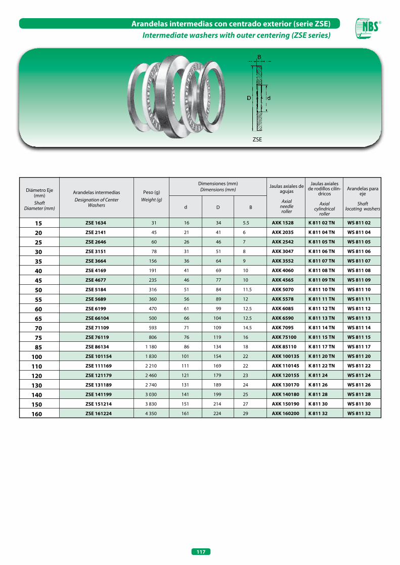
117
Arandelas intermedias con centrado exterior (serie ZSE)Intermediate washers with outer centering (ZSE series)
ZSE
15 20 25 30 35 40 45 50 55 60 65 70 75 85 100 110 120 130 140 150 160
Diámetro Eje (mm) Shaft
Diameter (mm)
Arandelas intermediasDesignation of Center
Washers
Peso (g)Weight (g)
Dimensiones (mm)Dimensions (mm)
d D B
Jaulas axiales de agujas
Axial needleroller
Jaulas axiales de rodillos cilín-
dricos
Axialcylindrical
roller
Arandelas para eje
Shaftlocating washers
ZSE 1634
ZSE 2141
ZSE 2646
ZSE 3151
ZSE 3664
ZSE 4169
ZSE 4677
ZSE 5184
ZSE 5689
ZSE 6199
ZSE 66104
ZSE 71109
ZSE 76119
ZSE 86134
ZSE 101154
ZSE 111169
ZSE 121179
ZSE 131189
ZSE 141199
ZSE 151214
ZSE 161224
31
45
60
78
156
191
235
316
360
470
500
593
806
1 180
1 830
2 210
2 460
2 740
3 030
3 830
4 350
16 34 5.5
21 41 6
26 46 7
31 51 8
36 64 9
41 69 10
46 77 10
51 84 11.5
56 89 12
61 99 12.5
66 104 12.5
71 109 14.5
76 119 16
86 134 18
101 154 22
111 169 22
121 179 23
131 189 24
141 199 25
151 214 27
161 224 29
AxK 1528 K 811 02 TN WS 811 02
AxK 2035 K 811 04 TN WS 811 04
AxK 2542 K 811 05 TN WS 811 05
AxK 3047 K 811 06 TN WS 811 06
AxK 3552 K 811 07 TN WS 811 07
AxK 4060 K 811 08 TN WS 811 08
AxK 4565 K 811 09 TN WS 811 09
AxK 5070 K 811 10 TN WS 811 10
AxK 5578 K 811 11 TN WS 811 11
AxK 6085 K 811 12 TN WS 811 12
AxK 6590 K 811 13 TN WS 811 13
AxK 7095 K 811 14 TN WS 811 14
AxK 75100 K 811 15 TN WS 811 15
AxK 85110 K 811 17 TN WS 811 17
AxK 100135 K 811 20 TN WS 811 20
AxK 110145 K 811 22 TN WS 811 22
AxK 120155 K 811 24 WS 811 24
AxK 130170 K 811 26 WS 811 26
AxK 140180 K 811 28 WS 811 28
AxK 150190 K 811 30 WS 811 30
AxK 160200 K 811 32 WS 811 32


RODILLOS DE APOyOYOKE TYPE TRACK ROLLERS
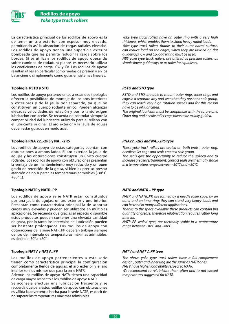
120
Rodillos de apoyoYoke type track rollers
La característica principal de los rodillos de apoyo es la de tener un aro exterior con espesor muy elevado, permitiendo así la absorcion de cargas radiales elevadas. Los rodillos de apoyo tienen una superficie exterior bombeada que les permite reducir la carga sobre los bordes. Si se utilizan los rodillos de apoyo operando sobre caminos de rodadura planos es necesario utilizar los coeficientes de carga Cw y Co. Los rodillos de apoyo resultan útiles en particular como ruedas de presión y en los balancines o simplemente como guías en sistemas lineales.
Tipología RSTO y STO
Los rodillos de apoyo pertenecientes a estas dos tipologías ofrecen la posibilidad de montaje de los aros interiores y exteriores y de la jaula por separado, ya que no constituyen un cuerpo rodante único. Pueden alcanzar elevadas velocidades de rotación y por lo tanto exigen lubricación con aceite. Se recuerda de controlar siempre la compatibilidad del lubricante utilizado para el relleno con el lubricante original. El aro exterior y la jaula de agujas deben estar guiados en modo axial.
Tipología RNA 22..-2RS y NA.. -2RS
Los rodillos de apoyo de estas categorías cuentan con obturaciones a ambos lados. El aro exterior, la jaula de agujas y las obturaciones constituyen un único cuerpo rodante. Los rodillos de apoyo con obturaciones presentan la ventaja de un mantenimiento muy reducido y un buen grado de retención de la grasa, si bien es preciso prestar atención de no superar las temperaturas admisibles (-30° C. +80° C).
Tipología NATR y NATR..PP
Los rodillos de apoyo serie NATR están constituidos por una jaula de agujas, un aro exterior y uno interior. Presentan como característica principal la de soportar cargas muy elevadas y pueden ser utilizados en múltiples aplicaciones. Se recuerda que gracias al espacio disponible estos productos pueden contener una elevada cantidad de grasa, por lo tanto los intervalos de lubricación pueden ser bastante prolongados. Los rodillos de apoyo con obturaciones de la serie NATR..PP deberán trabajar siempre dentro del intervalo de temperaturas máximas admisibles, es decir de -30° a +80°.
Tipología NATV y NATV.. PP
Los rodillos de apoyo pertenecientes a esta serie tienen como característica principal la configuración completamente llenos de agujas; el aro exterior y el aro interior son los mismos que para la serie NATR.Además los rodillos de apoyo NATV tienen una capacidad de carga mayor respecto a los rodillos de apoyo NATR.Se aconseja efectuar una lubricación frecuente y se recuerda que para estos rodillos de apoyo con obturaciones es válida la advertencia hecha para la serie NATR, es decir de no superar las temperaturas máximas admisibles.
Yoke type track rollers have an outer ring with a very high thickness, which enables them to stand heavy radial loads.Yoke type track rollers thanks to their outer barrel surface, can reduce load on the edges; when they are utilised on flat guideways, Cw and Co load rating must be used.NBS yoke type track rollers, are utilised as pressure rollers, as simple linear guideways or as roller for equalizers.
RSTo and STo type
RSTO and STO, are able to mount outer rings, inner rings and cage in a separate way and seen that they are not a sole group, they can reach very high rotation speeds and for this reason have to be oil lubricated.The original lubricant must be compatible with the future one. Outer ring and needle roller cage have to be axially guided.
RNA22..-2RS and NA..-2RS type
These yoke track rollers are sealed on both ends ; outer ring, needle roller cage and seals create a sole group.The seals give the opportunity to reduce the upkeep and to increase grease restrainment: contact seals are thermally stable in a temperature range between -30°C and +80°C.
NATR and NATR .. PP type
NATR and NATR..PP, are formed by a needle roller cage, by an outer and an inner ring; they can stand very heavy loads and can be used in many different applications.Thanks to the space available these products can contain big quantity of grease, therefore relubrication requires rather long interval.NATR..PP sealed type, are thermally stable in a temperature range between -30°C and +80°C.
NATV and NATV..PP type
The above yoke type track rollers have a full-complement design , outer and inner ring are the same as NATR ones.NATV have higher load ability respect to NATR.We recommend to relubricate them often and to not exceed temperatures suggested for NATR.
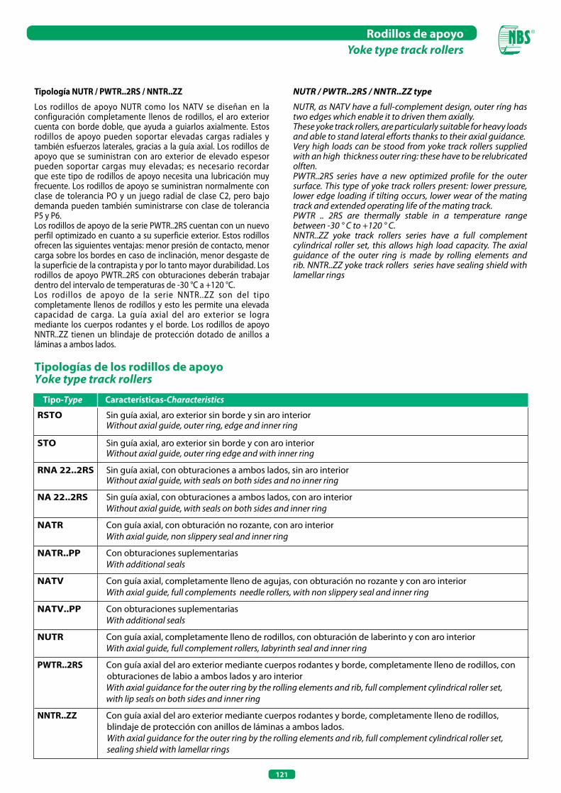
RSTO Sin guía axial, aro exterior sin borde y sin aro interior Without axial guide, outer ring, edge and inner ring
STO Sin guía axial, aro exterior sin borde y con aro interior Without axial guide, outer ring edge and with inner ring
RNA 22..2RS Sin guía axial, con obturaciones a ambos lados, sin aro interior Without axial guide, with seals on both sides and no inner ring
NA 22..2RS Sin guía axial, con obturaciones a ambos lados, con aro interior Without axial guide, with seals on both sides and inner ring
NATR Con guía axial, con obturación no rozante, con aro interior With axial guide, non slippery seal and inner ring
NATR..PP Con obturaciones suplementarias With additional seals
NATV Con guía axial, completamente lleno de agujas, con obturación no rozante y con aro interior With axial guide, full complements needle rollers, with non slippery seal and inner ring
NATV..PP Con obturaciones suplementarias With additional seals
NUTR Con guía axial, completamente lleno de rodillos, con obturación de laberinto y con aro interior With axial guide, full complement rollers, labyrinth seal and inner ring
PWTR..2RS Con guía axial del aro exterior mediante cuerpos rodantes y borde, completamente lleno de rodillos, con obturaciones de labio a ambos lados y aro interior
With axial guidance for the outer ring by the rolling elements and rib, full complement cylindrical roller set, with lip seals on both sides and inner ring
NNTR..ZZ Con guía axial del aro exterior mediante cuerpos rodantes y borde, completamente lleno de rodillos, blindaje de protección con anillos de láminas a ambos lados.
With axial guidance for the outer ring by the rolling elements and rib, full complement cylindrical roller set, sealing shield with lamellar rings
121
Rodillos de apoyoYoke type track rollers
Tipología NUTR / PWTR..2RS / NNTR..ZZ
Los rodillos de apoyo NUTR como los NATV se diseñan en la configuración completamente llenos de rodillos, el aro exterior cuenta con borde doble, que ayuda a guiarlos axialmente. Estos rodillos de apoyo pueden soportar elevadas cargas radiales y también esfuerzos laterales, gracias a la guía axial. Los rodillos de apoyo que se suministran con aro exterior de elevado espesor pueden soportar cargas muy elevadas; es necesario recordar que este tipo de rodillos de apoyo necesita una lubricación muy frecuente. Los rodillos de apoyo se suministran normalmente con clase de tolerancia PO y un juego radial de clase C2, pero bajo demanda pueden también suministrarse con clase de tolerancia P5 y P6.Los rodillos de apoyo de la serie PWTR..2RS cuentan con un nuevo perfil optimizado en cuanto a su superficie exterior. Estos rodillos ofrecen las siguientes ventajas: menor presión de contacto, menor carga sobre los bordes en caso de inclinación, menor desgaste de la superficie de la contrapista y por lo tanto mayor durabilidad. Los rodillos de apoyo PWTR..2RS con obturaciones deberán trabajar dentro del intervalo de temperaturas de -30 °C a +120 °C.Los rodillos de apoyo de la serie NNTR..ZZ son del tipo completamente llenos de rodillos y esto les permite una elevada capacidad de carga. La guía axial del aro exterior se logra mediante los cuerpos rodantes y el borde. Los rodillos de apoyo NNTR..ZZ tienen un blindaje de protección dotado de anillos a láminas a ambos lados.
Tipologías de los rodillos de apoyoYoke type track rollers
Tipo-Type Características-Characteristics
NUTR / PWTR..2RS / NNTR..ZZ type
NUTR, as NATV have a full-complement design, outer ríng has two edges which enable it to driven them axially.These yoke track rollers, are particularly suitable for heavy loads and able to stand lateral efforts thanks to their axial guidance.Very high loads can be stood from yoke track rollers supplied with an high thickness outer ring: these have to be relubricated olften.PWTR..2RS series have a new optimized profile for the outer surface. This type of yoke track rollers present: lower pressure, lower edge loading if tilting occurs, lower wear of the mating track and extended operating life of the mating track.PWTR .. 2RS are thermally stable in a temperature range between -30 ° C to +120 ° C.NNTR..ZZ yoke track rollers series have a full complement cylindrical roller set, this allows high load capacity. The axial guidance of the outer ring is made by rolling elements and rib. NNTR..ZZ yoke track rollers series have sealing shield with lamellar rings
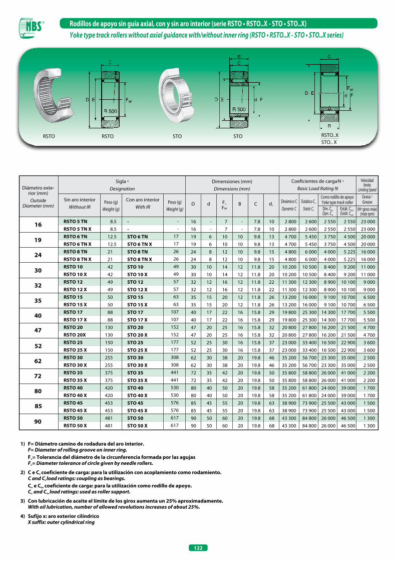
122
Rodillos de apoyo sin guía axial, con y sin aro interior (serie RSTO • RSTO..X - STO • STO..X)Yoke type track rollers without axial guidance with/without inner ring (RSTO • RSTO..X - STO • STO..X series)
1) F= Diámetro camino de rodadura del aro interior. F= Diameter of rolling groove on inner ring. Fw= Tolerancia del diámetro de la circunferencia formada por las agujas Fw= Diameter tolerance of circle given by needle rollers.
2) C e C0 coeficiente de carga: para la utilización con acoplamiento como rodamiento. C and C0 load ratings: coupling as bearings. Cw e C0w coeficiente de carga: para la utilización como rodillo de apoyo. Cw and C0w load ratings: used as roller support.
3) Con lubricación de aceite el límite de los giros aumenta un 25% aproximadamente. With oil lubrication, number of allowed revolutions increases of about 25%.
4) Sufijo x: aro exterior cilíndrico X suffix: outer cylindrical ring
Diámetro exte-rior (mm)
OutsideDiameter (mm)
Dimensiones (mm)Dimensions (mm)
Coeficientes de carga N 2)
Basic Load Rating N
Dinámico CDynamic C
D d
16
24
RSTO 5 TN RSTO 5 TN x RSTO 6 TN RSTO 6 TN x RSTO 8 TN RSTO 8 TN x RSTO 10 RSTO 10 x RSTO 12 RSTO 12 x RSTO 15 RSTO 15 x RSTO 17 RSTO 17 x RSTO 20 RSTO 20x RSTO 25 RSTO 25 x RSTO 30 RSTO 30 x RSTO 35 RSTO 35 x RSTO 40 RSTO 40 x RSTO 45 RSTO 45 x RSTO 50 RSTO 50 x
8.5
8.5
12.5
12.5
21
21
42
42
49
49
50
50
88
88
130
130
150
150
255
255
375
375
420
420
453
453
481
481
16 - 7 - 7.8 10
16 - 7 - 7.8 10
19 6 10 10 9.8 13
19 6 10 10 9.8 13
24 8 12 10 9.8 15
24 8 12 10 9.8 15
30 10 14 12 11.8 20
30 10 14 12 11.8 20
32 12 16 12 11.8 22
32 12 16 12 11.8 22
35 15 20 12 11.8 26
35 15 20 12 11.8 26
40 17 22 16 15.8 29
40 17 22 16 15.8 29
47 20 25 16 15.8 32
47 20 25 16 15.8 32
52 25 30 16 15.8 37
52 25 30 16 15.8 37
62 30 38 20 19.8 46
62 30 38 20 19.8 46
72 35 42 20 19.8 50
72 35 42 20 19.8 50
80 40 50 20 19.8 58
80 40 50 20 19.8 58
85 45 55 20 19.8 63
85 45 55 20 19.8 63
90 50 60 20 19.8 68
90 50 60 20 19.8 68
2 800 2 600 2 550 2 550 23 000
2 800 2 600 2 550 2 550 23 000
4 700 5 450 3 750 4 500 20 000
4 700 5 450 3 750 4 500 20 000
4 800 6 000 4 000 5 225 16 000
4 800 6 000 4 000 5 225 16 000
10 200 10 500 8 400 9 200 11 000
10 200 10 500 8 400 9 200 11 000
11 300 12 300 8 900 10 100 9 000
11 300 12 300 8 900 10 100 9 000
13 200 16 000 9 100 10 700 6 500
13 200 16 000 9 100 10 700 6 500
19 800 25 300 14 300 17 700 5 500
19 800 25 300 14 300 17 700 5 500
20 800 27 800 16 200 21 500 4 700
20 800 27 800 16 200 21 500 4 700
23 000 33 400 16 500 22 900 3 600
23 000 33 400 16 500 22 900 3 600
35 200 56 700 23 300 35 000 2 500
35 200 56 700 23 300 35 000 2 500
35 800 58 800 26 000 41 000 2 200
35 800 58 800 26 000 41 000 2 200
35 200 61 800 24 000 39 000 1 700
35 200 61 800 24 000 39 000 1 700
38 900 73 900 25 500 43 000 1 500
38 900 73 900 25 500 43 000 1 500
43 300 84 800 26 000 46 500 1 300
43 300 84 800 26 000 46 500 1 300
19
30
80
Grasa 3) Grease
Velocidad limite
Limiting Speed
Sigla 4)
Designation
Sin aro interiorWithout IR
Peso (g)Weight (g)
Con aro interiorWith IR
F1)
FwB C d1
Estático Co
Static Co (Nº giros máx)(máx rpm)
Como rodillo de apoyoYoke type track rollerDin. Cw
Dyn. Cw
Estát. Cow
Estát. Cow
32
35
40
47
52
62
72
85
90
- - STO 6 TN STO 6 TN x STO 8 TN STO 8 TN x STO 10 STO 10 x STO 12 STO 12 x STO 15 STO 15 x STO 17 STO 17 x STO 20 STO 20 x STO 25 STO 25 x STO 30 STO 30 x STO 35 STO 35 x STO 40 STO 40 x STO 45 STO 45 x STO 50 STO 50 x
-
-
17
17
26
26
49
49
57
57
63
63
107
107
152
152
177
177
308
308
441
441
530
530
576
576
617
617
Peso (g)Weight (g)
RSTO STOSTORSTO RSTO..XSTO.. X
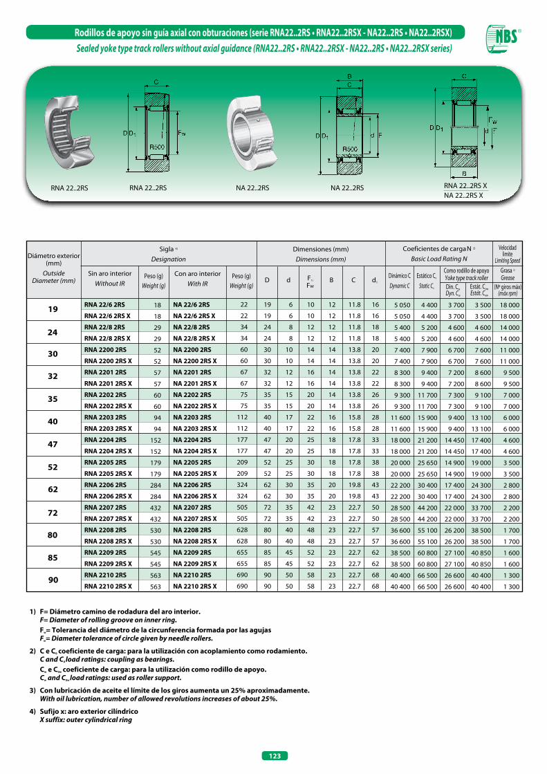
123
Rodillos de apoyo sin guía axial con obturaciones (serie RNA22..2RS • RNA22..2RSX - NA22..2RS • NA22..2RSX)Sealed yoke type track rollers without axial guidance (RNA22..2RS • RNA22..2RSX - NA22..2RS • NA22..2RSX series)
RNA 22..2RS NA 22..2RSNA 22..2RS
1) F= Diámetro camino de rodadura del aro interior. F= Diameter of rolling groove on inner ring. Fw= Tolerancia del diámetro de la circunferencia formada por las agujas Fw= Diameter tolerance of circle given by needle rollers.
2) C e C0 coeficiente de carga: para la utilización con acoplamiento como rodamiento. C and C0 load ratings: coupling as bearings. Cw e C0w coeficiente de carga: para la utilización como rodillo de apoyo. Cw and C0w load ratings: used as roller support.
3) Con lubricación de aceite el límite de los giros aumenta un 25% aproximadamente. With oil lubrication, number of allowed revolutions increases of about 25%.
4) Sufijo x: aro exterior cilíndrico X suffix: outer cylindrical ring
RNA 22..2RS
19
30
24
32
85
35
40
47
52
62
72
80
90
Diámetro exterior (mm)
OutsideDiameter (mm)
Dimensiones (mm)Dimensions (mm)
Coeficientes de carga N 2)
Basic Load Rating N
Dinámico CDynamic C
D dGrasa 3) Grease
Velocidad limite
Limiting Speed
Sigla 4)
Designation
Sin aro interiorWithout IR
Peso (g)Weight (g)
Con aro interiorWith IR
F1)
FwB C d1
Estático Co
Static Co (Nº giros máx)(máx rpm)
Como rodillo de apoyoYoke type track rollerDin. Cw
Dyn. Cw
Estát. Cow
Estát. Cow
Peso (g)Weight (g)
RNA 22/6 2RS
RNA 22/6 2RS x
RNA 22/8 2RS
RNA 22/8 2RS x
RNA 2200 2RS
RNA 2200 2RS x
RNA 2201 2RS
RNA 2201 2RS x
RNA 2202 2RS
RNA 2202 2RS x
RNA 2203 2RS
RNA 2203 2RS x
RNA 2204 2RS
RNA 2204 2RS x
RNA 2205 2RS
RNA 2205 2RS x
RNA 2206 2RS
RNA 2206 2RS x
RNA 2207 2RS
RNA 2207 2RS x
RNA 2208 2RS
RNA 2208 2RS x
RNA 2209 2RS
RNA 2209 2RS x
RNA 2210 2RS
RNA 2210 2RS x
18
18
29
29
52
52
57
57
60
60
94
94
152
152
179
179
284
284
432
432
530
530
545
545
563
563
19 6 10 12 11.8 16
19 6 10 12 11.8 16
24 8 12 12 11.8 18
24 8 12 12 11.8 18
30 10 14 14 13.8 20
30 10 14 14 13.8 20
32 12 16 14 13.8 22
32 12 16 14 13.8 22
35 15 20 14 13.8 26
35 15 20 14 13.8 26
40 17 22 16 15.8 28
40 17 22 16 15.8 28
47 20 25 18 17.8 33
47 20 25 18 17.8 33
52 25 30 18 17.8 38
52 25 30 18 17.8 38
62 30 35 20 19.8 43
62 30 35 20 19.8 43
72 35 42 23 22.7 50
72 35 42 23 22.7 50
80 40 48 23 22.7 57
80 40 48 23 22.7 57
85 45 52 23 22.7 62
85 45 52 23 22.7 62
90 50 58 23 22.7 68
90 50 58 23 22.7 68
5 050 4 400 3 700 3 500 18 000
5 050 4 400 3 700 3 500 18 000
5 400 5 200 4 600 4 600 14 000
5 400 5 200 4 600 4 600 14 000
7 400 7 900 6 700 7 600 11 000
7 400 7 900 6 700 7 600 11 000
8 300 9 400 7 200 8 600 9 500
8 300 9 400 7 200 8 600 9 500
9 300 11 700 7 300 9 100 7 000
9 300 11 700 7 300 9 100 7 000
11 600 15 900 9 400 13 100 6 000
11 600 15 900 9 400 13 100 6 000
18 000 21 200 14 450 17 400 4 600
18 000 21 200 14 450 17 400 4 600
20 000 25 650 14 900 19 000 3 500
20 000 25 650 14 900 19 000 3 500
22 200 30 400 17 400 24 300 2 800
22 200 30 400 17 400 24 300 2 800
28 500 44 200 22 000 33 700 2 200
28 500 44 200 22 000 33 700 2 200
36 600 55 100 26 200 38 500 1 700
36 600 55 100 26 200 38 500 1 700
38 500 60 800 27 100 40 850 1 600
38 500 60 800 27 100 40 850 1 600
40 400 66 500 26 600 40 400 1 300
40 400 66 500 26 600 40 400 1 300
22
22
34
34
60
60
67
67
75
75
112
112
177
177
209
209
324
324
505
505
628
628
655
655
690
690
NA 22/6 2RS
NA 22/6 2RS x
NA 22/8 2RS
NA 22/8 2RS x
NA 2200 2RS
NA 2200 2RS x
NA 2201 2RS
NA 2201 2RS x
NA 2202 2RS
NA 2202 2RS x
NA 2203 2RS
NA 2203 2RS x
NA 2204 2RS
NA 2204 2RS x
NA 2205 2RS
NA 2205 2RS x
NA 2206 2RS
NA 2206 2RS x
NA 2207 2RS
NA 2207 2RS x
NA 2208 2RS
NA 2208 2RS x
NA 2209 2RS
NA 2209 2RS x
NA 2210 2RS
NA 2210 2RS x
RNA 22..2RS XNA 22..2RS X
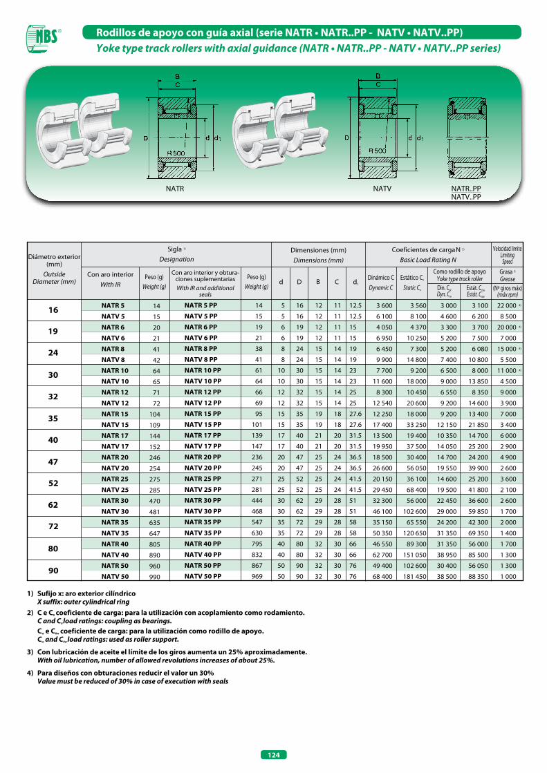
124
Rodillos de apoyo con guía axial (serie NATR • NATR..PP - NATV • NATV..PP)Yoke type track rollers with axial guidance (NATR • NATR..PP - NATV • NATV..PP series)
NATR NATV NATR..PPNATV..PP
1) Sufijo x: aro exterior cilíndrico X suffix: outer cylindrical ring2) C e C0 coeficiente de carga: para la utilización con acoplamiento como rodamiento. C and C0 load ratings: coupling as bearings. Cw e C0w coeficiente de carga: para la utilización como rodillo de apoyo. Cw and C0w load ratings: used as roller support.
3) Con lubricación de aceite el límite de los giros aumenta un 25% aproximadamente. With oil lubrication, number of allowed revolutions increases of about 25%.
4) Para diseños con obturaciones reducir el valor un 30% Value must be reduced of 30% in case of execution with seals
(Nº giros máx)(máx rpm)
Diámetro exterior (mm)
OutsideDiameter (mm)
Dimensiones (mm)Dimensions (mm)
Coeficientes de carga N 2)
Basic Load Rating N
Dinámico CDynamic C
d DGrasa 3) Grease
Velocidad limiteLimiting
Speed
Sigla 1)
Designation
Con aro interiorWith IR
Peso (g)Weight (g)
Con aro interior y obtura-ciones suplementariasWith IR and additional
seals
B C d1
Estático Co
Static Co
Como rodillo de apoyoYoke type track rollerDin. Cw
Dyn. Cw
Estát. Cow
Estát. Cow
Peso (g)Weight (g)
16
24
19
30
80
32
35
40
47
52
62
72
90
NATR 5
NATV 5
NATR 6
NATV 6
NATR 8
NATV 8
NATR 10
NATV 10
NATR 12
NATV 12
NATR 15
NATV 15
NATR 17
NATV 17
NATR 20
NATV 20
NATR 25
NATV 25
NATR 30
NATV 30
NATR 35
NATV 35
NATR 40
NATV 40
NATR 50
NATV 50
14
15
20
21
41
42
64
65
71
72
104
109
144
152
246
254
275
285
470
481
635
647
805
890
960
990
5 16 12 11 12.5
5 16 12 11 12.5
6 19 12 11 15
6 19 12 11 15
8 24 15 14 19
8 24 15 14 19
10 30 15 14 23
10 30 15 14 23
12 32 15 14 25
12 32 15 14 25
15 35 19 18 27.6
15 35 19 18 27.6
17 40 21 20 31.5
17 40 21 20 31.5
20 47 25 24 36.5
20 47 25 24 36.5
25 52 25 24 41.5
25 52 25 24 41.5
30 62 29 28 51
30 62 29 28 51
35 72 29 28 58
35 72 29 28 58
40 80 32 30 66
40 80 32 30 66
50 90 32 30 76
50 90 32 30 76
14
15
19
21
38
41
61
64
66
69
95
101
139
147
236
245
271
281
444
468
547
630
795
832
867
969
NATR 5 PP
NATV 5 PP
NATR 6 PP
NATV 6 PP
NATR 8 PP
NATV 8 PP
NATR 10 PP
NATV 10 PP
NATR 12 PP
NATV 12 PP
NATR 15 PP
NATV 15 PP
NATR 17 PP
NATV 17 PP
NATR 20 PP
NATV 20 PP
NATR 25 PP
NATV 25 PP
NATR 30 PP
NATV 30 PP
NATR 35 PP
NATV 35 PP
NATR 40 PP
NATV 40 PP
NATR 50 PP
NATV 50 PP
3 600 3 560 3 000 3 100 22 000 4)
6 100 8 100 4 600 6 200 8 500
4 050 4 370 3 300 3 700 20 000 4)
6 950 10 250 5 200 7 500 7 000
6 450 7 300 5 200 6 080 15 000 4)
9 900 14 800 7 400 10 800 5 500
7 700 9 200 6 500 8 000 11 000 4)
11 600 18 000 9 000 13 850 4 500
8 300 10 450 6 550 8 350 9 000
12 540 20 600 9 200 14 600 3 900
12 250 18 000 9 200 13 400 7 000
17 400 33 250 12 150 21 850 3 400
13 500 19 400 10 350 14 700 6 000
19 950 37 500 14 050 25 200 2 900
18 500 30 400 14 700 24 200 4 900
26 600 56 050 19 550 39 900 2 600
20 150 36 100 14 600 25 200 3 600
29 450 68 400 19 500 41 800 2 100
32 300 56 000 22 450 36 600 2 600
46 100 102 600 29 000 59 850 1 700
35 150 65 550 24 200 42 300 2 000
50 350 120 650 31 350 69 350 1 400
46 550 89 300 31 350 56 000 1 700
62 700 151 050 38 950 85 500 1 300
49 400 102 600 30 400 56 050 1 300
68 400 181 450 38 500 88 350 1 000
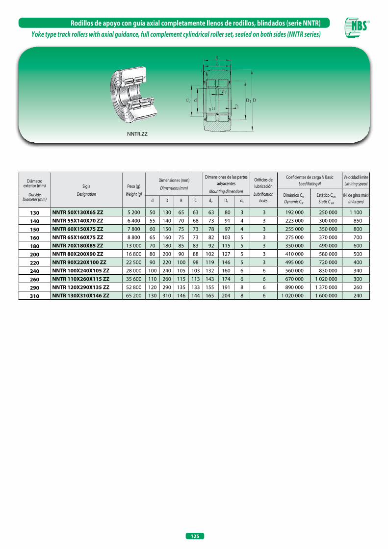
125
Rodillos de apoyo con guía axial completamente llenos de rodillos, blindados (serie NNTR)Yoke type track rollers with axial guidance, full complement cylindrical roller set, sealed on both sides (NNTR series)
Diámetro exterior (mm)
OutsideDiameter (mm)
Sigla
Designation
Peso (g)
Weight (g)
Dimensiones (mm)
Dimensions (mm)
Dimensiones de las partes adyacentes
Mounting dimensions
Orificios de lubricación
Lubrification holes
Coeficientes de carga N BasicLoad Rating N
Velocidad limiteLimiting speed
Dinámico CW
Dynamic CW
Estático C0W
Static C 0W
(Nº de giros máx)(máx rpm)d D B C d2 D1 d3
130 NNTR 50x130x65 ZZ 5 200 50 130 65 63 63 80 3 3 192 000 250 000 1 100
140 NNTR 55x140x70 ZZ 6 400 55 140 70 68 73 91 4 3 223 000 300 000 850
150 NNTR 60x150x75 ZZ 7 800 60 150 75 73 78 97 4 3 255 000 350 000 800
160 NNTR 65x160x75 ZZ 8 800 65 160 75 73 82 103 5 3 275 000 370 000 700
180 NNTR 70x180x85 ZZ 13 000 70 180 85 83 92 115 5 3 350 000 490 000 600
200 NNTR 80x200x90 ZZ 16 800 80 200 90 88 102 127 5 3 410 000 580 000 500
220 NNTR 90x220x100 ZZ 22 500 90 220 100 98 119 146 5 3 495 000 720 000 400
240 NNTR 100x240x105 ZZ 28 000 100 240 105 103 132 160 6 6 560 000 830 000 340
260 NNTR 110x260x115 ZZ 35 600 110 260 115 113 143 174 6 6 670 000 1 020 000 300
290 NNTR 120x290x135 ZZ 52 800 120 290 135 133 155 191 8 6 890 000 1 370 000 260
310 NNTR 130x310x146 ZZ 65 200 130 310 146 144 165 204 8 6 1 020 000 1 600 000 240
NNTR.ZZ
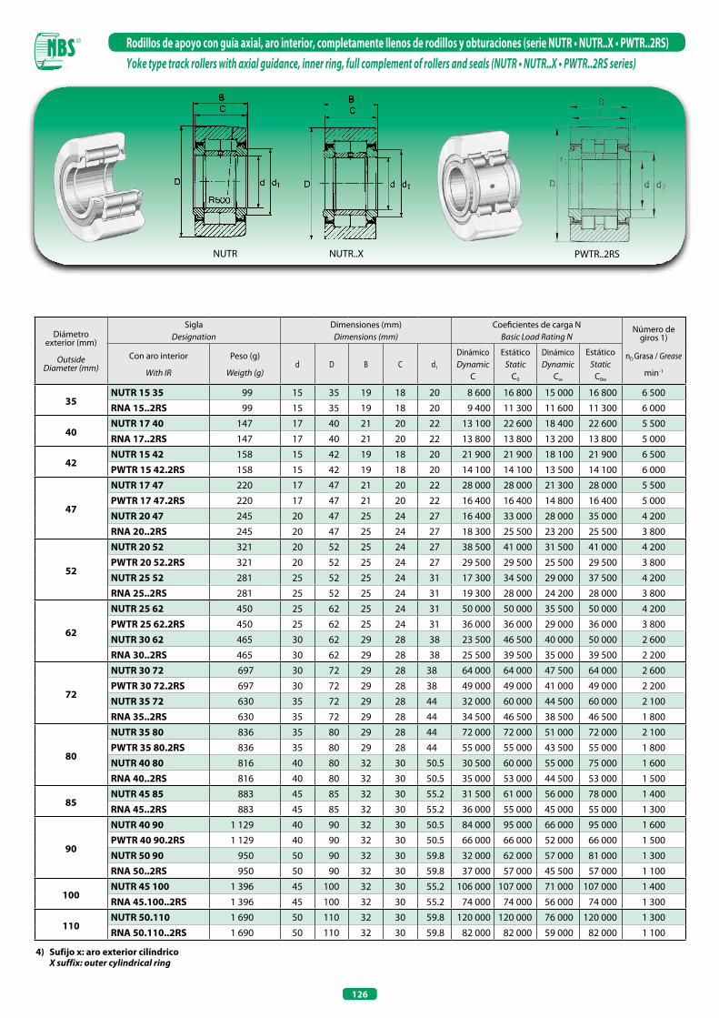
126
Rodillos de apoyo con guía axial, aro interior, completamente llenos de rodillos y obturaciones (serie NUTR • NUTR..X • PWTR..2RS)Yoke type track rollers with axial guidance, inner ring, full complement of rollers and seals (NUTR • NUTR..X • PWTR..2RS series)
Diámetroexterior (mm)
OutsideDiameter (mm)
SiglaDesignation
Dimensiones (mm)Dimensions (mm)
Coeficientes de carga NBasic Load Rating N
Número de giros 1)
nD Grasa / Grease
min-1
Con aro interior
With IR
Peso (g)
Weigth (g)d D B C d1
Dinámico Dynamic
C
EstáticoStatic
C0
Dinámico Dynamic
Cw
EstáticoStatic
C0w
35NUTR 15 35 99 15 35 19 18 20 8 600 16 800 15 000 16 800 6 500RNA 15..2RS 99 15 35 19 18 20 9 400 11 300 11 600 11 300 6 000
40NUTR 17 40 147 17 40 21 20 22 13 100 22 600 18 400 22 600 5 500RNA 17..2RS 147 17 40 21 20 22 13 800 13 800 13 200 13 800 5 000
42NUTR 15 42 158 15 42 19 18 20 21 900 21 900 18 100 21 900 6 500PWTR 15 42.2RS 158 15 42 19 18 20 14 100 14 100 13 500 14 100 6 000
47
NUTR 17 47 220 17 47 21 20 22 28 000 28 000 21 300 28 000 5 500PWTR 17 47.2RS 220 17 47 21 20 22 16 400 16 400 14 800 16 400 5 000NUTR 20 47 245 20 47 25 24 27 16 400 33 000 28 000 35 000 4 200RNA 20..2RS 245 20 47 25 24 27 18 300 25 500 23 200 25 500 3 800
52
NUTR 20 52 321 20 52 25 24 27 38 500 41 000 31 500 41 000 4 200PWTR 20 52.2RS 321 20 52 25 24 27 29 500 29 500 25 500 29 500 3 800NUTR 25 52 281 25 52 25 24 31 17 300 34 500 29 000 37 500 4 200RNA 25..2RS 281 25 52 25 24 31 19 300 28 000 24 200 28 000 3 800
62
NUTR 25 62 450 25 62 25 24 31 50 000 50 000 35 500 50 000 4 200PWTR 25 62.2RS 450 25 62 25 24 31 36 000 36 000 29 000 36 000 3 800NUTR 30 62 465 30 62 29 28 38 23 500 46 500 40 000 50 000 2 600RNA 30..2RS 465 30 62 29 28 38 25 500 39 500 35 000 39 500 2 200
72
NUTR 30 72 697 30 72 29 28 38 64 000 64 000 47 500 64 000 2 600PWTR 30 72.2RS 697 30 72 29 28 38 49 000 49 000 41 000 49 000 2 200NUTR 35 72 630 35 72 29 28 44 32 000 60 000 44 500 60 000 2 100RNA 35..2RS 630 35 72 29 28 44 34 500 46 500 38 500 46 500 1 800
80
NUTR 35 80 836 35 80 29 28 44 72 000 72 000 51 000 72 000 2 100PWTR 35 80.2RS 836 35 80 29 28 44 55 000 55 000 43 500 55 000 1 800NUTR 40 80 816 40 80 32 30 50.5 30 500 60 000 55 000 75 000 1 600RNA 40..2RS 816 40 80 32 30 50.5 35 000 53 000 44 500 53 000 1 500
85NUTR 45 85 883 45 85 32 30 55.2 31 500 61 000 56 000 78 000 1 400RNA 45..2RS 883 45 85 32 30 55.2 36 000 55 000 45 000 55 000 1 300
90
NUTR 40 90 1 129 40 90 32 30 50.5 84 000 95 000 66 000 95 000 1 600PWTR 40 90.2RS 1 129 40 90 32 30 50.5 66 000 66 000 52 000 66 000 1 500NUTR 50 90 950 50 90 32 30 59.8 32 000 62 000 57 000 81 000 1 300RNA 50..2RS 950 50 90 32 30 59.8 37 000 57 000 45 500 57 000 1 100
100NUTR 45 100 1 396 45 100 32 30 55.2 106 000 107 000 71 000 107 000 1 400RNA 45.100..2RS 1 396 45 100 32 30 55.2 74 000 74 000 56 000 74 000 1 300
110NUTR 50.110 1 690 50 110 32 30 59.8 120 000 120 000 76 000 120 000 1 300RNA 50.110..2RS 1 690 50 110 32 30 59.8 82 000 82 000 59 000 82 000 1 100
NUTR NUTR..X PWTR..2RS
4) Sufijo x: aro exterior cilíndrico X suffix: outer cylindrical ring
RODILLOS DE LEVASSTUD TYPE TRACK ROLLERS
128
Rodillos de levasStud type track rollers
Los rodillos de levas están formados por un perno con borde de acero, superficies de guía, aro exterior de gran espesor, capaz de soportar cargas radiales elevadas. Gracias a la forma particular del aro exterior (superficie bombeada) el rodillo de levas logra reducir la concentración de las cargas en los bordes. Además gracias a la rosca del perno son fáciles de montar. Para la relubricación existen orificios tanto en la superficie lateral del perno como también en la parte roscada. Cuando se utiliza el rodillo de levas en un camino de rodadura plano puede verificarse una deformación elástica del aro exterior, por lo tanto es conveniente adoptar los coeficientes de carga Cw y Cow como base de referencia. Los rodillos de levas pueden ser utilizados en diversas aplicaciones como los rodillos de presión, los rodillos para balancines o las guías lineales simples.
Tipología KR y KR..PP
Los rodillos de levas constituyen un único grupo de montaje, ya que están formados por un perno con borde, un aro exterior, una jaula de agujas y una arandela de guía. Los rodillos de levas de esta categoría son idóneos para soportar elevadas cargas y gracias al espacio presente entre las agujas no es necesario lubricarlos muy frecuentemente. Se recuerda que cuando se utilizan los rodillos de levas con obturaciones no se debe superar el intervalo de temperaturas entre los -30° C. y los +80° C.
Tipología KRV y KRV..PP
Los rodillos de levas de la serie KRV son símiles a los de la serie KR, pero son del tipo completamente llenos de agujas, soportan cargas más elevadas y alcanzan velocidades de rotación inferiores. Estos rodillos de levas requieren una lubricación frecuente. Se recuerda siempre que si están dotados de obturaciones se deberán respetar las temperaturas máximas previstas (véase serie KR)
Tipología NUKR / PWKR
Los rodillos de levas de esta serie están compuestos por un perno con borde, un aro exterior con bordes guíado por agujas, un cuerpo rodante del tipo completamente lleno de agujas. Todos estos componentes constituyen una única unidad lista para el montaje. Este tipo de rodillos de levas garantiza la absorción de elevadas cargas y gracias a su guía axial pueden soportar grandes esfuerzos laterales. Se recuerda que los rodillos de levas NUKR / PWKR cuentan con un orificio de lubricación también en el vástago. Si no se utiliza dicho orificio es aconsejable cerrarlo con un tapón. Si en cambio si se utiliza, la lubricación deberá ser frecuente.
Stud type track rollers consist of a stud with a steel edge, of an outer ring with a wider thickness and of a rolling element able to stand heavy radial loads.Thanks to the particular shape of its barrel outer ring, stud can reduce load concentration on the sharp edges; besides an easier assembling is assured by a thread which is present onto the stud.Concerning lubrication, holes are located on both lateral surface and part of stud with thread.When the stud is mounted on a plane guideway an elastic deformation of outer ring could happen, this is why it seems to be suitable using Cw and Cow coefficients.Stud type track rollers are used as pressure rollers, rollers for compensators or in linear guideways.
KR and KR ..PP type
Stud type track rollers are a sole group of assembling as they consist of a stud with edge, an outer ring, needle roller cage and a fifth wheel.The KR are suitable to stand heavy loads and thanks to the space, it is not necessary to lubricate them often.The sealed KR are thermally stable in the temperature range between -30°C +80°C.
KRV and KRV..PP type
The same as above but able to stand heavier loads, lower rotation speeds and with a full complement of needle rollers.The KRV require a frequent lubrication and seen that they can also be supplied with seals, we remind you not to exceed maximum temperature above indicated for KR.
NUKR / PWKR type
The NUKR consist of a stud, of an outer ring with edges guided by rollers, and of a full complement of needle rollers: the combination of these elements creates a sole group ready to be assembled.Thanks to their properties, NUKR / PWKR are able to stand very heavy loads; these are axially guided to stand heavy lateral efforts.All NUKR have a further lubrication hole on their shaft: if this isn’t exploited, we recommend to close it with an appropriate cap.Lubrication has to be frequently repeated.
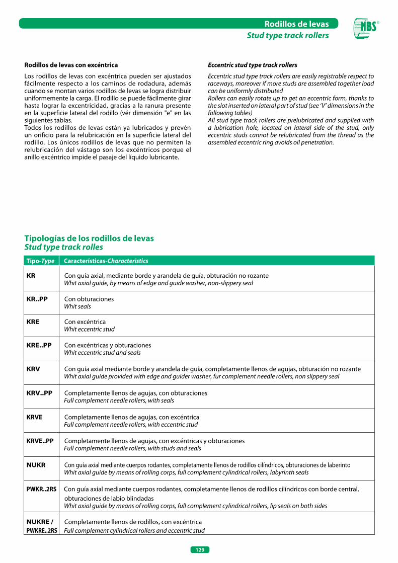
129
Rodillos de levasStud type track rollers
Rodillos de levas con excéntrica
Los rodillos de levas con excéntrica pueden ser ajustados fácilmente respecto a los caminos de rodadura, además cuando se montan varios rodillos de levas se logra distribuir uniformemente la carga. El rodillo se puede fácilmente girar hasta lograr la excentricidad, gracias a la ranura presente en la superficie lateral del rodillo (vér dimensión "e" en las siguientes tablas.Todos los rodillos de levas están ya lubricados y prevén un orificio para la relubricación en la superficie lateral del rodillo. Los únicos rodillos de levas que no permiten la relubricación del vástago son los excéntricos porque el anillo excéntrico impide el pasaje del líquido lubricante.
Tipologías de los rodillos de levasStud type track rollesTipo-Type Características-Characteristics
KR Con guía axial, mediante borde y arandela de guía, obturación no rozante Whit axial guide, by means of edge and guide washer, non-slippery seal
KR..PP Con obturaciones Whit seals
KRE Con excéntrica Whit eccentric stud
KRE..PP Con excéntricas y obturaciones Whit eccentric stud and seals
KRV Con guía axial mediante borde y arandela de guía, completamente llenos de agujas, obturación no rozante Whit axial guide provided with edge and guider washer, fur complement needle rollers, non slippery seal
KRV..PP Completamente llenos de agujas, con obturaciones Full complement needle rollers, with seals
KRVE Completamente llenos de agujas, con excéntrica Full complement needle rollers, with eccentric stud
KRVE..PP Completamente llenos de agujas, con excéntricas y obturaciones Full complement needle rollers, with studs and seals
NUKR Con guía axial mediante cuerpos rodantes, completamente llenos de rodillos cilíndricos, obturaciones de laberinto Whit axial guide by means of rolling corps, full complement cylindrical rollers, labyrinth seals
PWKR..2RS Con guía axial mediante cuerpos rodantes, completamente llenos de rodillos cilíndricos con borde central, obturaciones de labio blindadas
Whit axial guide by means of rolling corps, full complement cylindrical rollers, lip seals on both sides
NUKRE / Completamente llenos de rodillos, con excéntricaPWKRE..2RS Full complement cylindrical rollers and eccentric stud
Eccentric stud type track rollers
Eccentric stud type track rollers are easily registrable respect to raceways, moreover if more studs are assembled together load can be uniformly distributedRollers can easily rotate up to get an eccentric form, thanks to the slot inserted on lateral part of stud (see ‘V’ dimensions in the following tables)All stud type track rollers are prelubricated and supplied with a lubrication hole, located on lateral side of the stud, only eccentric studs cannot be relubricated from the thread as the assembled eccentric ring avoids oil penetration.
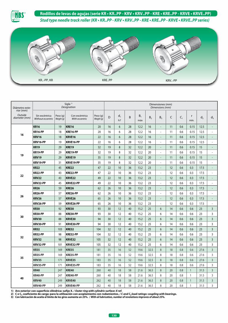
130
Rodillos de levas de agujas (serie KR • KR..PP - KRV • KRV..PP - KRE • KRE..PP - KRVE • KRVE..PP)Stud type needle track roller (KR • KR..PP - KRV • KRV..PP - KRE • KRE..PP - KRVE • KRVE..PP series)
1) Aro exterior con superficie cilíndrica: sufijo x. / outer ring with cylindric surface: X ref.2) C e C0 coeficiente de carga: para la utilización con acoplamiento con rodamientos. / C and C0 load ratings: coupling with bearings.3) Con lubricación de aceite el límite de los giros aumenta un 25%. / With oil lubrication, number of revolutions improves of about 25%.
Diámetro exte-rior (mm)
Outsidediameter (mm)
Sigla 1)
DesignationDimensiones (mm)
Dimensions (mm)
Sin excéntricaWithout eccentric
Peso (g)Weight (g)
Con excéntricaWith eccentric
Peso (g)Weight (g) D d1
h7B B1
máxB2 B3 C C1
rmín.
d2 d3
16
KR16 19 KRE16 20 16 6 28 12.2 16 - 11 0.6 0.15 12.5 -
KR16-PP 18 KRE16-PP 20 16 6 28 12.2 16 - 11 0.6 0.15 12.5 -
KRV16 18 KRVE16 22 16 6 28 12.2 16 - 11 0.6 0.15 12.5 -
KRV16-PP 19 KRVE16-PP 22 16 6 28 12.2 16 - 11 0.6 0.15 12.5 -
19
KR19 29 KRE19 32 19 8 32 12.2 20 - 11 0.6 0.15 15 -
KR19-PP 29 KRE19-PP 32 19 8 32 12.2 20 - 11 0.6 0.15 15 -
KRV19 29 KRVE19 35 19 8 32 12.2 20 - 11 0.6 0.15 15 -
KRV19-PP 31 KRVE19-PP 35 19 8 32 12.2 20 - 11 0.6 0.15 15 -
22
KR22 45 KRE22 47 22 10 36 13.2 23 - 12 0.6 0.3 17.5 -
KR22-PP 43 KRE22-PP 47 22 10 36 13.2 23 - 12 0.6 0.3 17.5 -
KRV22 43 KRVE22 49 22 10 36 13.2 23 - 12 0.6 0.3 17.5 -
KRV22-PP 45 KRVE22-PP 49 22 10 36 13.2 23 - 12 0.6 0.3 17.5 -
26
KR26 59 KRE26 62 26 10 36 13.2 23 - 12 0.6 0.3 17.5 -
KR26-PP 57 KRE26-PP 62 26 10 36 13.2 23 - 12 0.6 0.3 17.5 -
KRV26 57 KRVE26 65 26 10 36 13.2 23 - 12 0.6 0.3 17.5 -
KRV26-PP 59 KRVE26-PP 65 26 10 36 13.2 23 - 12 0.6 0.3 17.5 -
30
KR30 92 KRE30 93 30 12 40 15.2 25 6 14 0.6 0.6 23 3
KR30-PP 88 KRE30-PP 93 30 12 40 15.2 25 6 14 0.6 0.6 23 3
KRV30 88 KRVE30 94 30 12 40 15.2 25 6 14 0.6 0.6 23 3
KRV30-PP 91 KRVE30-PP 94 30 12 40 15.2 25 6 14 0.6 0.6 23 3
32
KR32 103 KRE32 104 32 12 40 15.2 25 6 14 0.6 0.6 23 3
KR32-PP 98 KRE32-PP 104 32 12 40 15.2 25 6 14 0.6 0.6 23 3
KRV32 98 KRVE32 105 32 12 40 15.2 25 6 14 0.6 0.6 23 3
KRV32-PP 101 KRVE32-PP 105 32 12 40 15.2 25 6 14 0.6 0.6 23 3
35
KR35 169 KRE35 181 35 16 52 19.6 32.5 8 18 0.8 0.6 27.6 3
KR35-PP 169 KRE35-PP 181 35 16 52 19.6 32.5 8 18 0.8 0.6 27.6 3
KRV35 171 KRVE35 183 35 16 52 19.6 32.5 8 18 0.8 0.6 27.6 3
KRV35-PP 171 KRVE35-PP 183 35 16 52 19.6 32.5 8 18 0.8 0.6 27.6 3
40
KR40 247 KRE40 260 40 18 58 21.6 36.5 8 20 0.8 1 31.5 3
KR40-PP 247 KRE40-PP 260 40 18 58 21.6 36.5 8 20 0.8 1 31.5 3
KRV40 249 KRVE40 262 40 18 58 21.6 36.5 8 20 0.8 1 31.5 3
KRV40-PP 249 KRVE40-PP 262 40 18 58 21.6 36.5 8 20 0.8 1 31.5 3
KRE..PPKR..-PP, KR KRV..-PP

131
Rodillos de levas de agujas (serie KR • KR..PP - KRV • KRV..PP - KRE • KRE..PP - KRVE • KRVE..PP)Stud type needle track roller (KR • KR..PP - KRV • KRV..PP - KRE • KRE..PP - KRVE • KRVE..PP series)
Dimensiones (mm)Dimensions (mm) Niples
engrasadoresGrease nipples
Par de aprieteNut tightening
torque
MA
Nm
Coeficientes de carga 2)
Basic load rating 2)Carga límite
de fatiga Fatigue load
Cuw
N
Velocidad límite Limiting speed
DinámicoDynamic
Cw
EstáticoStatic
C0w
G lG WExcéntrica - Eccentric Grasa - Grease 3)
de
h9Be e N° giros máx - N° max rpm
M6(X1) 8 - 9 7 0.5 NIP1 3 3 150 3 300 415 14 000
M6(X1) 8 - 9 7 0.5 NIP1 3 3 150 3 300 415 14 000
M6(X1) 8 - 9 7 0.5 NIP1 3 4 900 6 500 860 3 000
M6(X1) 8 - 9 7 0.5 NIP1 3 4 900 6 500 860 3 000
M8(X1,25) 10 - 11 9 0.5 NIP1 8 3 500 3 900 485 11 000
M8(X1,25) 10 - 11 9 0.5 NIP1 8 3 500 3 900 485 11 000
M8(X1,25) 10 - 11 9 0.5 NIP1 8 5 400 7 900 1 040 3 100
M8(X1,25) 10 - 11 9 0.5 NIP1 8 5 400 7 900 1 040 3 100
M10X1 12 - 13 10 0.5 NIP1X4.5 15 4 500 5 200 650 8 000
M10X1 12 - 13 10 0.5 NIP1X4.5 15 4 500 5 200 650 8 000
M10X1 12 - 13 10 0.5 NIP1X4.5 15 6 200 9 100 1 110 2 600
M10X1 12 - 13 10 0.5 NIP1X4.5 15 6 200 9 100 1 110 2 600
M10X1 12 5 13 10 0.5 NIP1X4.5 15 5 100 6 200 770 8 000
M10X1 12 5 13 10 0.5 NIP1X4.5 15 5 100 6 200 770 8 000
M10X1 12 5 13 10 0.5 NIP1X4.5 15 7 300 11 300 1 380 2 600
M10X1 12 5 13 10 0.5 NIP1X4.5 15 7 300 11 300 1 380 2 600
M12X1,5 13 6 15 11 0.5 NIP1X4.5 22 6 800 8 400 1 070 5 500
M12X1,5 13 6 15 11 0.5 NIP1X4.5 22 6 800 8 400 1 070 5 500
M12X1,5 13 6 15 11 0.5 NIP1X4.5 22 9 500 14 600 1 840 2 100
M12X1,5 13 6 15 11 0.5 NIP1X4.5 22 9 500 14 600 1 840 2 100
M12X1,5 13 6 15 11 0.5 NIP1X4.5 22 7 100 8 900 1 140 5 500
M12X1,5 13 6 15 11 0.5 NIP1X4.5 22 7 100 8 900 1 140 5 500
M12X1,5 13 6 15 11 0.5 NIP1X4.5 22 10 500 15 800 1 990 2 100
M12X1,5 13 6 15 11 0.5 NIP1X4.5 22 10 500 15 800 1 990 2 100
M16X1,5 17 8 20 14 1 NIP2X7.5 58 9 800 14 100 1 700 3 600
M16X1,5 17 8 20 14 1 NIP2X7.5 58 9 800 14 100 1 700 3 600
M16X1,5 17 8 20 14 1 NIP2X7.5 58 12 800 23 000 2 900 1 600
M16X1,5 17 8 20 14 1 NIP2X7.5 58 12 800 23 000 2 900 1 600
M18X1,5 19 8 22 16 1 NIP2X7.5 87 10 900 15 500 1 850 2 900
M18X1,5 19 8 22 16 1 NIP2X7.5 87 10 900 15 500 1 850 2 900
M18X1,5 19 8 22 16 1 NIP2X7.5 87 14 800 26 500 3 050 1 400
M18X1,5 19 8 22 16 1 NIP2X7.5 87 14 800 26 500 3 050 1 400
KR..-PP, KR KRE..-PP KRV..-PP
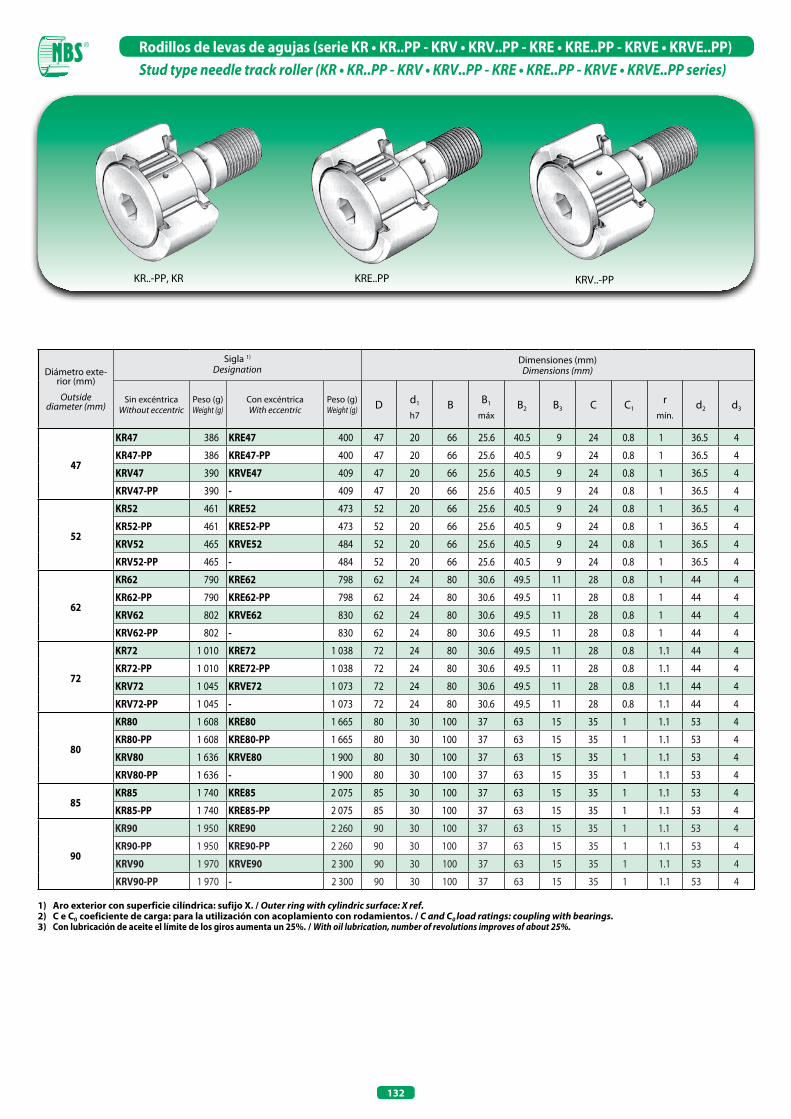
132
Rodillos de levas de agujas (serie KR • KR..PP - KRV • KRV..PP - KRE • KRE..PP - KRVE • KRVE..PP)Stud type needle track roller (KR • KR..PP - KRV • KRV..PP - KRE • KRE..PP - KRVE • KRVE..PP series)
Diámetro exte-rior (mm)
Outsidediameter (mm)
Sigla 1)
DesignationDimensiones (mm)
Dimensions (mm)
Sin excéntricaWithout eccentric
Peso (g)Weight (g)
Con excéntricaWith eccentric
Peso (g)Weight (g) D d1
h7B B1
máxB2 B3 C C1
rmín.
d2 d3
47
KR47 386 KRE47 400 47 20 66 25.6 40.5 9 24 0.8 1 36.5 4
KR47-PP 386 KRE47-PP 400 47 20 66 25.6 40.5 9 24 0.8 1 36.5 4
KRV47 390 KRVE47 409 47 20 66 25.6 40.5 9 24 0.8 1 36.5 4
KRV47-PP 390 - 409 47 20 66 25.6 40.5 9 24 0.8 1 36.5 4
52
KR52 461 KRE52 473 52 20 66 25.6 40.5 9 24 0.8 1 36.5 4
KR52-PP 461 KRE52-PP 473 52 20 66 25.6 40.5 9 24 0.8 1 36.5 4
KRV52 465 KRVE52 484 52 20 66 25.6 40.5 9 24 0.8 1 36.5 4
KRV52-PP 465 - 484 52 20 66 25.6 40.5 9 24 0.8 1 36.5 4
62
KR62 790 KRE62 798 62 24 80 30.6 49.5 11 28 0.8 1 44 4
KR62-PP 790 KRE62-PP 798 62 24 80 30.6 49.5 11 28 0.8 1 44 4
KRV62 802 KRVE62 830 62 24 80 30.6 49.5 11 28 0.8 1 44 4
KRV62-PP 802 - 830 62 24 80 30.6 49.5 11 28 0.8 1 44 4
72
KR72 1 010 KRE72 1 038 72 24 80 30.6 49.5 11 28 0.8 1.1 44 4
KR72-PP 1 010 KRE72-PP 1 038 72 24 80 30.6 49.5 11 28 0.8 1.1 44 4
KRV72 1 045 KRVE72 1 073 72 24 80 30.6 49.5 11 28 0.8 1.1 44 4
KRV72-PP 1 045 - 1 073 72 24 80 30.6 49.5 11 28 0.8 1.1 44 4
80
KR80 1 608 KRE80 1 665 80 30 100 37 63 15 35 1 1.1 53 4
KR80-PP 1 608 KRE80-PP 1 665 80 30 100 37 63 15 35 1 1.1 53 4
KRV80 1 636 KRVE80 1 900 80 30 100 37 63 15 35 1 1.1 53 4
KRV80-PP 1 636 - 1 900 80 30 100 37 63 15 35 1 1.1 53 4
85KR85 1 740 KRE85 2 075 85 30 100 37 63 15 35 1 1.1 53 4
KR85-PP 1 740 KRE85-PP 2 075 85 30 100 37 63 15 35 1 1.1 53 4
90
KR90 1 950 KRE90 2 260 90 30 100 37 63 15 35 1 1.1 53 4
KR90-PP 1 950 KRE90-PP 2 260 90 30 100 37 63 15 35 1 1.1 53 4
KRV90 1 970 KRVE90 2 300 90 30 100 37 63 15 35 1 1.1 53 4
KRV90-PP 1 970 - 2 300 90 30 100 37 63 15 35 1 1.1 53 4
1) Aro exterior con superficie cilíndrica: sufijo x. / outer ring with cylindric surface: X ref.2) C e C0 coeficiente de carga: para la utilización con acoplamiento con rodamientos. / C and C0 load ratings: coupling with bearings.3) Con lubricación de aceite el límite de los giros aumenta un 25%. / With oil lubrication, number of revolutions improves of about 25%.
KRE..PPKR..-PP, KR KRV..-PP
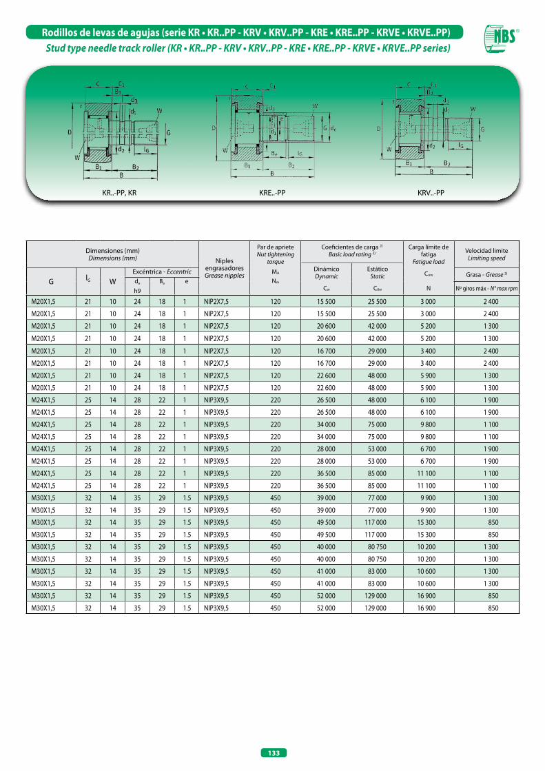
133
Rodillos de levas de agujas (serie KR • KR..PP - KRV • KRV..PP - KRE • KRE..PP - KRVE • KRVE..PP)Stud type needle track roller (KR • KR..PP - KRV • KRV..PP - KRE • KRE..PP - KRVE • KRVE..PP series)
Dimensiones (mm)Dimensions (mm) Niples
engrasadoresGrease nipples
Par de aprieteNut tightening
torque
MA
Nm
Coeficientes de carga 2)
Basic load rating 2)Carga límite de
fatigaFatigue load
Cuw
N
Velocidad limiteLimiting speed
DinámicoDynamic
Cw
EstáticoStatic
C0w
G lG WExcéntrica - Eccentric Grasa - Grease 3)
de
h9Be e
Nº giros máx - N° max rpm
M20X1,5 21 10 24 18 1 NIP2X7,5 120 15 500 25 500 3 000 2 400
M20X1,5 21 10 24 18 1 NIP2X7,5 120 15 500 25 500 3 000 2 400
M20X1,5 21 10 24 18 1 NIP2X7,5 120 20 600 42 000 5 200 1 300
M20X1,5 21 10 24 18 1 NIP2X7,5 120 20 600 42 000 5 200 1 300
M20X1,5 21 10 24 18 1 NIP2X7,5 120 16 700 29 000 3 400 2 400
M20X1,5 21 10 24 18 1 NIP2X7,5 120 16 700 29 000 3 400 2 400
M20X1,5 21 10 24 18 1 NIP2X7,5 120 22 600 48 000 5 900 1 300
M20X1,5 21 10 24 18 1 NIP2X7,5 120 22 600 48 000 5 900 1 300
M24X1,5 25 14 28 22 1 NIP3X9,5 220 26 500 48 000 6 100 1 900
M24X1,5 25 14 28 22 1 NIP3X9,5 220 26 500 48 000 6 100 1 900
M24X1,5 25 14 28 22 1 NIP3X9,5 220 34 000 75 000 9 800 1 100
M24X1,5 25 14 28 22 1 NIP3X9,5 220 34 000 75 000 9 800 1 100
M24X1,5 25 14 28 22 1 NIP3X9,5 220 28 000 53 000 6 700 1 900
M24X1,5 25 14 28 22 1 NIP3X9,5 220 28 000 53 000 6 700 1 900
M24X1,5 25 14 28 22 1 NIP3X9,5 220 36 500 85 000 11 100 1 100
M24X1,5 25 14 28 22 1 NIP3X9,5 220 36 500 85 000 11 100 1 100
M30X1,5 32 14 35 29 1.5 NIP3X9,5 450 39 000 77 000 9 900 1 300
M30X1,5 32 14 35 29 1.5 NIP3X9,5 450 39 000 77 000 9 900 1 300
M30X1,5 32 14 35 29 1.5 NIP3X9,5 450 49 500 117 000 15 300 850
M30X1,5 32 14 35 29 1.5 NIP3X9,5 450 49 500 117 000 15 300 850
M30X1,5 32 14 35 29 1.5 NIP3X9,5 450 40 000 80 750 10 200 1 300
M30X1,5 32 14 35 29 1.5 NIP3X9,5 450 40 000 80 750 10 200 1 300
M30X1,5 32 14 35 29 1.5 NIP3X9,5 450 41 000 83 000 10 600 1 300
M30X1,5 32 14 35 29 1.5 NIP3X9,5 450 41 000 83 000 10 600 1 300
M30X1,5 32 14 35 29 1.5 NIP3X9,5 450 52 000 129 000 16 900 850
M30X1,5 32 14 35 29 1.5 NIP3X9,5 450 52 000 129 000 16 900 850
KR..-PP, KR KRE..-PP KRV..-PP
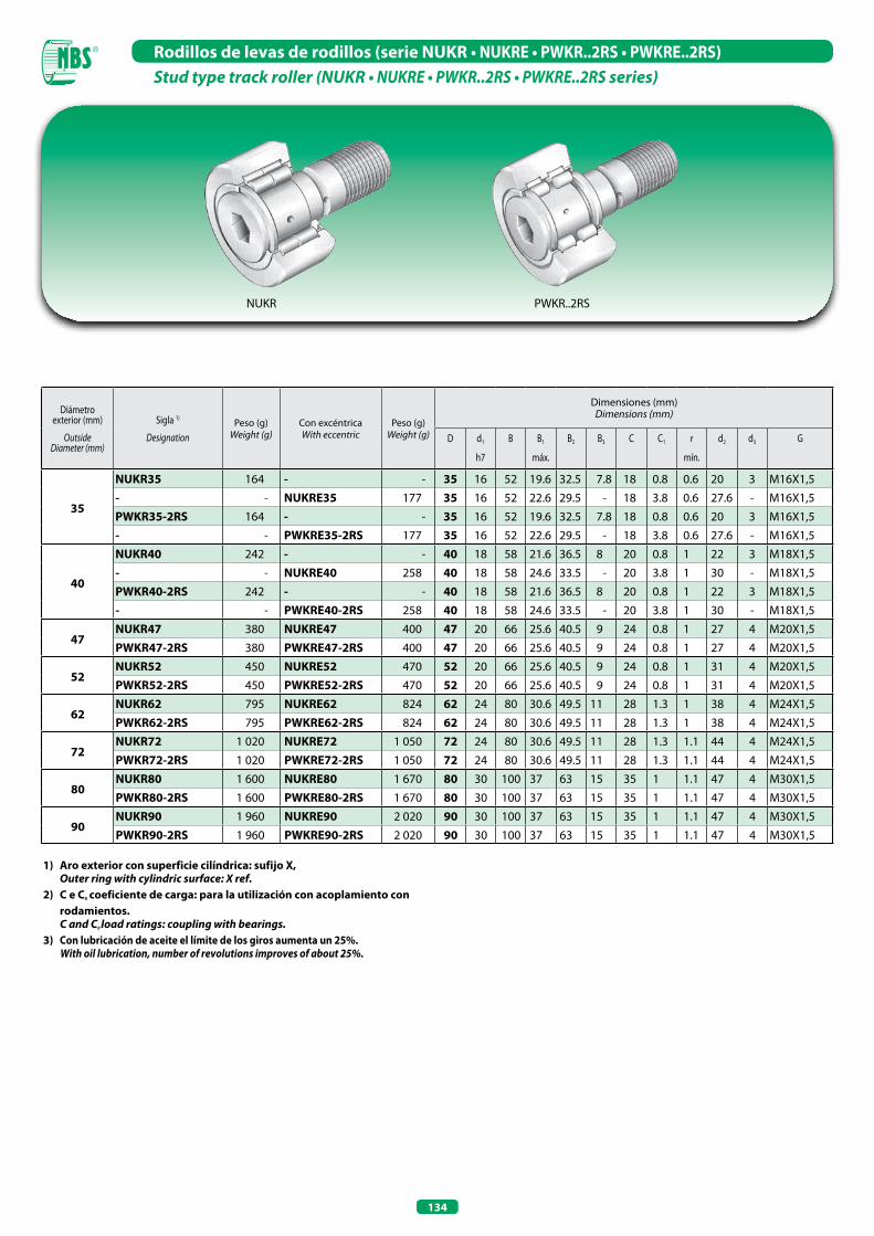
134
Rodillos de levas de rodillos (serie NUKR • NUKRE • PWKR..2RS • PWKRE..2RS)Stud type track roller (NUKR • NUKRE • PWKR..2RS • PWKRE..2RS series)
1) Aro exterior con superficie cilíndrica: sufijo x, outer ring with cylindric surface: X ref.2) C e C0 coeficiente de carga: para la utilización con acoplamiento con
rodamientos. C and C0 load ratings: coupling with bearings.3) Con lubricación de aceite el límite de los giros aumenta un 25%. With oil lubrication, number of revolutions improves of about 25%.
Diámetro exterior (mm)
OutsideDiameter (mm)
Sigla 1)
DesignationPeso (g)
Weight (g)Con excéntricaWith eccentric
Peso (g)Weight (g)
Dimensiones (mm)Dimensions (mm)
D d1
h7
B B1
máx.
B2 B3 C C1 r
mín.
d2 d3 G
35
NUKR35 164 - - 35 16 52 19.6 32.5 7.8 18 0.8 0.6 20 3 M16X1,5
- - NUKRE35 177 35 16 52 22.6 29.5 - 18 3.8 0.6 27.6 - M16X1,5
PWKR35-2RS 164 - - 35 16 52 19.6 32.5 7.8 18 0.8 0.6 20 3 M16X1,5
- - PWKRE35-2RS 177 35 16 52 22.6 29.5 - 18 3.8 0.6 27.6 - M16X1,5
40
NUKR40 242 - - 40 18 58 21.6 36.5 8 20 0.8 1 22 3 M18X1,5
- - NUKRE40 258 40 18 58 24.6 33.5 - 20 3.8 1 30 - M18X1,5
PWKR40-2RS 242 - - 40 18 58 21.6 36.5 8 20 0.8 1 22 3 M18X1,5
- - PWKRE40-2RS 258 40 18 58 24.6 33.5 - 20 3.8 1 30 - M18X1,5
47NUKR47 380 NUKRE47 400 47 20 66 25.6 40.5 9 24 0.8 1 27 4 M20X1,5
PWKR47-2RS 380 PWKRE47-2RS 400 47 20 66 25.6 40.5 9 24 0.8 1 27 4 M20X1,5
52NUKR52 450 NUKRE52 470 52 20 66 25.6 40.5 9 24 0.8 1 31 4 M20X1,5
PWKR52-2RS 450 PWKRE52-2RS 470 52 20 66 25.6 40.5 9 24 0.8 1 31 4 M20X1,5
62NUKR62 795 NUKRE62 824 62 24 80 30.6 49.5 11 28 1.3 1 38 4 M24X1,5
PWKR62-2RS 795 PWKRE62-2RS 824 62 24 80 30.6 49.5 11 28 1.3 1 38 4 M24X1,5
72NUKR72 1 020 NUKRE72 1 050 72 24 80 30.6 49.5 11 28 1.3 1.1 44 4 M24X1,5
PWKR72-2RS 1 020 PWKRE72-2RS 1 050 72 24 80 30.6 49.5 11 28 1.3 1.1 44 4 M24X1,5
80NUKR80 1 600 NUKRE80 1 670 80 30 100 37 63 15 35 1 1.1 47 4 M30X1,5
PWKR80-2RS 1 600 PWKRE80-2RS 1 670 80 30 100 37 63 15 35 1 1.1 47 4 M30X1,5
90NUKR90 1 960 NUKRE90 2 020 90 30 100 37 63 15 35 1 1.1 47 4 M30X1,5
PWKR90-2RS 1 960 PWKRE90-2RS 2 020 90 30 100 37 63 15 35 1 1.1 47 4 M30X1,5
PWKR..2RSNUKR
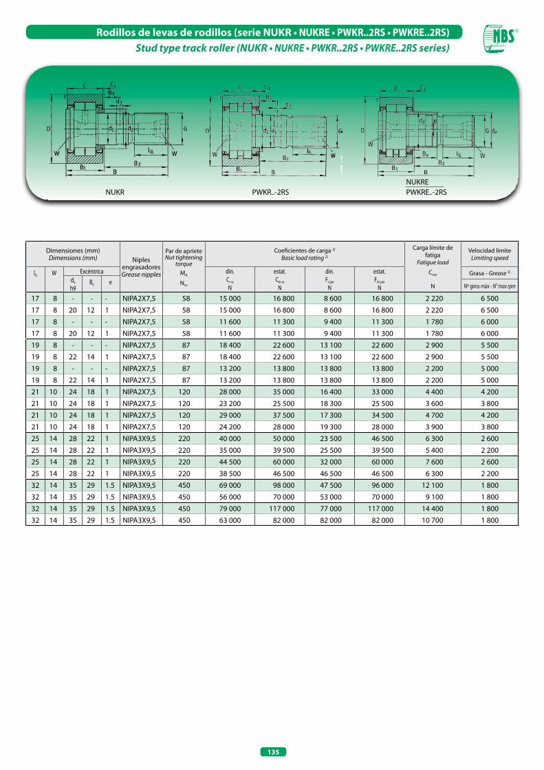
135
Rodillos de levas de rodillos (serie NUKR • NUKRE • PWKR..2RS • PWKRE..2RS)Stud type track roller (NUKR • NUKRE • PWKR..2RS • PWKRE..2RS series)
Dimensiones (mm)Dimensions (mm) Niples
engrasadoresGrease nipples
Par de aprieteNut tightening
torqueMA
Nm
Coeficientes de carga 2)
Basic load rating 2)
Carga límite de fatiga
Fatigue load
Cuw
N
Velocidad limiteLimiting speed
lG W Excéntrica din.Cr w
N
estat.C0r w
N
din.Fr per
N
estat.F0r per
N
Grasa - Grease 3)
de
h9Be e Nº giros máx - N° max rpm
17 8 - - - NIPA2X7,5 58 15 000 16 800 8 600 16 800 2 220 6 500
17 8 20 12 1 NIPA2X7,5 58 15 000 16 800 8 600 16 800 2 220 6 500
17 8 - - - NIPA2X7,5 58 11 600 11 300 9 400 11 300 1 780 6 000
17 8 20 12 1 NIPA2X7,5 58 11 600 11 300 9 400 11 300 1 780 6 000
19 8 - - - NIPA2X7,5 87 18 400 22 600 13 100 22 600 2 900 5 500
19 8 22 14 1 NIPA2X7,5 87 18 400 22 600 13 100 22 600 2 900 5 500
19 8 - - - NIPA2X7,5 87 13 200 13 800 13 800 13 800 2 200 5 000
19 8 22 14 1 NIPA2X7,5 87 13 200 13 800 13 800 13 800 2 200 5 000
21 10 24 18 1 NIPA2X7,5 120 28 000 35 000 16 400 33 000 4 400 4 200
21 10 24 18 1 NIPA2X7,5 120 23 200 25 500 18 300 25 500 3 600 3 800
21 10 24 18 1 NIPA2X7,5 120 29 000 37 500 17 300 34 500 4 700 4 200
21 10 24 18 1 NIPA2X7,5 120 24 200 28 000 19 300 28 000 3 900 3 800
25 14 28 22 1 NIPA3X9,5 220 40 000 50 000 23 500 46 500 6 300 2 600
25 14 28 22 1 NIPA3X9,5 220 35 000 39 500 25 500 39 500 5 400 2 200
25 14 28 22 1 NIPA3X9,5 220 44 500 60 000 32 000 60 000 7 600 2 600
25 14 28 22 1 NIPA3X9,5 220 38 500 46 500 46 500 46 500 6 300 2 200
32 14 35 29 1.5 NIPA3X9,5 450 69 000 98 000 47 500 96 000 12 100 1 800
32 14 35 29 1.5 NIPA3X9,5 450 56 000 70 000 53 000 70 000 9 100 1 800
32 14 35 29 1.5 NIPA3X9,5 450 79 000 117 000 77 000 117 000 14 400 1 800
32 14 35 29 1.5 NIPA3X9,5 450 63 000 82 000 82 000 82 000 10 700 1 800
NUKR PWKR..-2RSNUKREPWKRE..-2RS

RODILLOS DE APOyO DE UNA y DOS HILERAS DE BOLAS WHEELS WITH SINGLE OR DOUBLE ROW BALLS

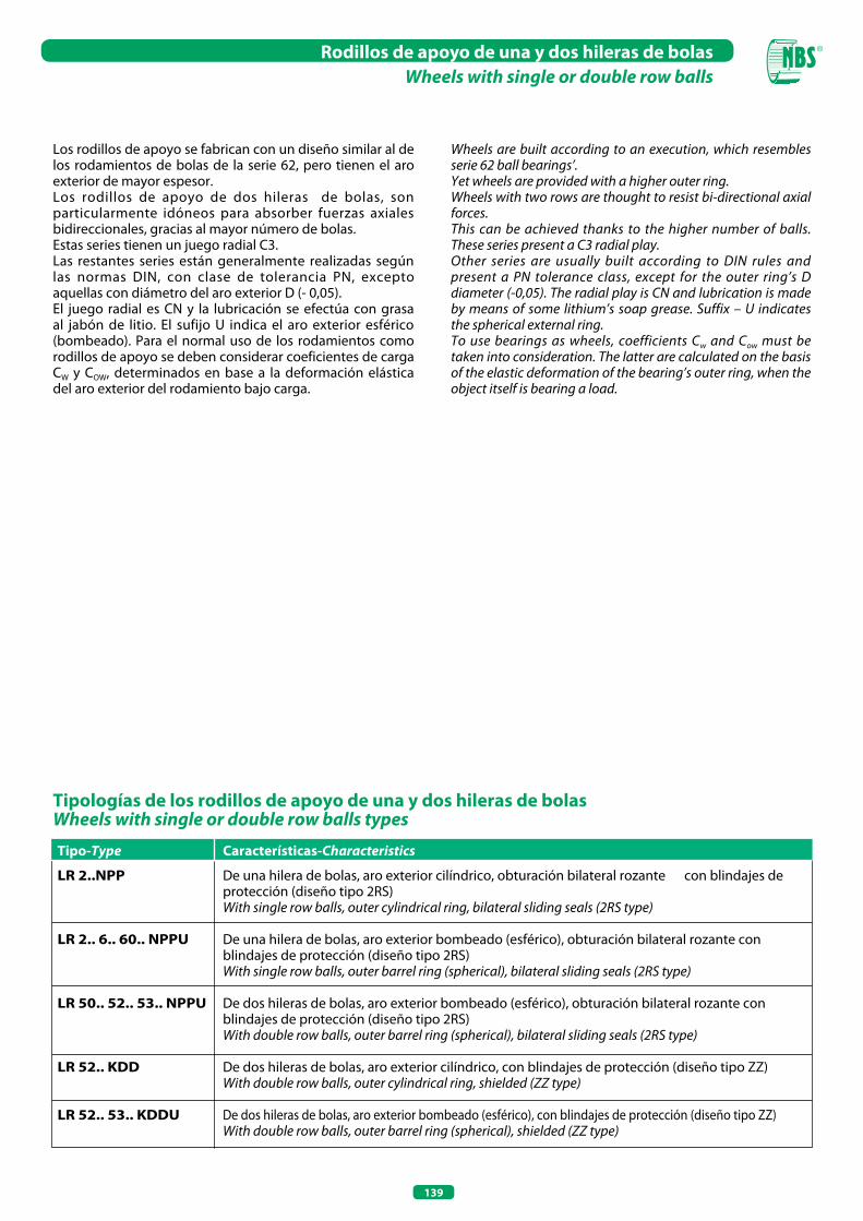
139
Rodillos de apoyo de una y dos hileras de bolas Wheels with single or double row balls
Los rodillos de apoyo se fabrican con un diseño similar al de los rodamientos de bolas de la serie 62, pero tienen el aro exterior de mayor espesor. Los rodillos de apoyo de dos hileras de bolas, son particularmente idóneos para absorber fuerzas axiales bidireccionales, gracias al mayor número de bolas. Estas series tienen un juego radial C3.Las restantes series están generalmente realizadas según las normas DIN, con clase de tolerancia PN, excepto aquellas con diámetro del aro exterior D (- 0,05). El juego radial es CN y la lubricación se efectúa con grasa al jabón de litio. El sufijo U indica el aro exterior esférico (bombeado). Para el normal uso de los rodamientos como rodillos de apoyo se deben considerar coeficientes de carga CW y COW, determinados en base a la deformación elástica del aro exterior del rodamiento bajo carga.
Tipo-Type Características-Characteristics
LR 2..NPP De una hilera de bolas, aro exterior cilíndrico, obturación bilateral rozante con blindajes de protección (diseño tipo 2RS) With single row balls, outer cylindrical ring, bilateral sliding seals (2RS type)
LR 2.. 6.. 60.. NPPU De una hilera de bolas, aro exterior bombeado (esférico), obturación bilateral rozante con blindajes de protección (diseño tipo 2RS) With single row balls, outer barrel ring (spherical), bilateral sliding seals (2RS type)
LR 50.. 52.. 53.. NPPU De dos hileras de bolas, aro exterior bombeado (esférico), obturación bilateral rozante con blindajes de protección (diseño tipo 2RS) With double row balls, outer barrel ring (spherical), bilateral sliding seals (2RS type)
LR 52.. KDD De dos hileras de bolas, aro exterior cilíndrico, con blindajes de protección (diseño tipo ZZ) With double row balls, outer cylindrical ring, shielded (ZZ type)
LR 52.. 53.. KDDU De dos hileras de bolas, aro exterior bombeado (esférico), con blindajes de protección (diseño tipo ZZ) With double row balls, outer barrel ring (spherical), shielded (ZZ type)
Tipologías de los rodillos de apoyo de una y dos hileras de bolasWheels with single or double row balls types
Wheels are built according to an execution, which resembles serie 62 ball bearings’. Yet wheels are provided with a higher outer ring. Wheels with two rows are thought to resist bi-directional axial forces. This can be achieved thanks to the higher number of balls. These series present a C3 radial play.Other series are usually built according to DIN rules and present a PN tolerance class, except for the outer ring’s D diameter (-0,05). The radial play is CN and lubrication is made by means of some lithium’s soap grease. Suffix – U indicates the spherical external ring. To use bearings as wheels, coefficients Cw and Cow must be taken into consideration. The latter are calculated on the basis of the elastic deformation of the bearing’s outer ring, when the object itself is bearing a load.
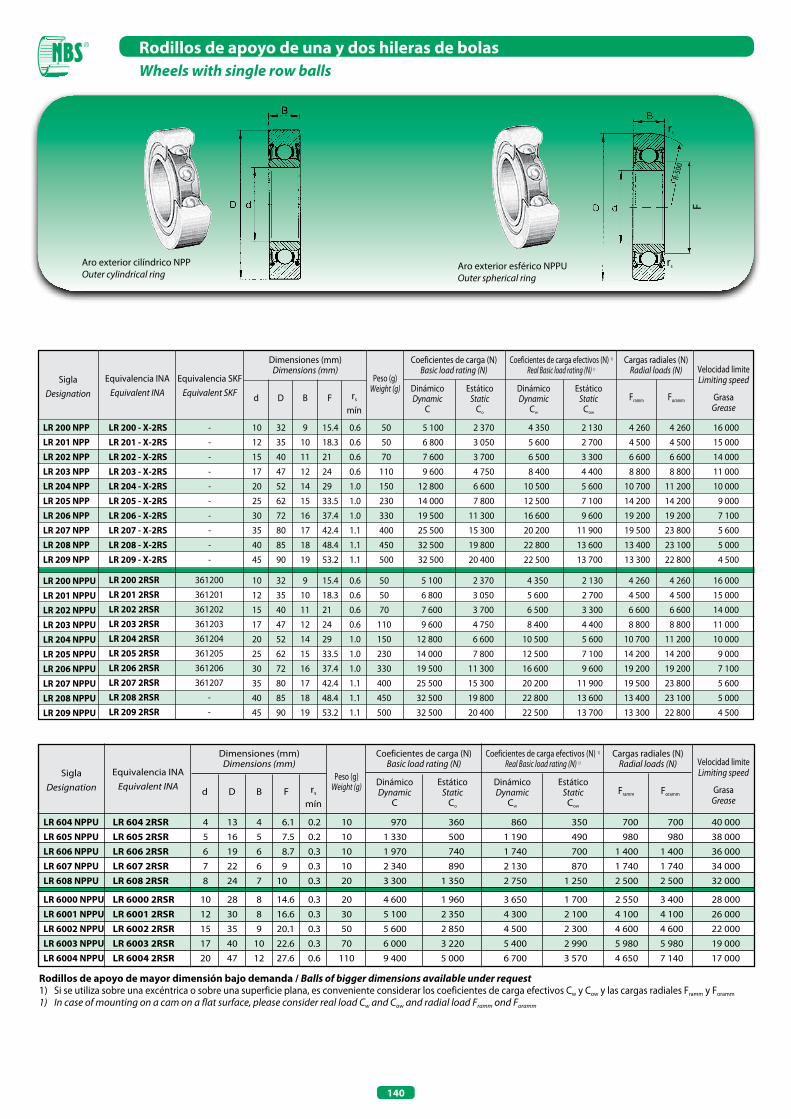
140
Rodillos de apoyo de una y dos hileras de bolas Wheels with single row balls
Rodillos de apoyo de mayor dimensión bajo demanda / Balls of bigger dimensions available under request1) Si se utiliza sobre una excéntrica o sobre una superficie plana, es conveniente considerar los coeficientes de carga efectivos Cw y Cow y las cargas radiales Framm y Foramm
1) In case of mounting on a cam on a flat surface, please consider real load Cw and Cow and radial load Framm ond Foramm
rs
rs
R-50
0
Aro exterior cilíndrico NPPOuter cylindrical ring
Aro exterior esférico NPPUOuter spherical ring
SiglaDesignation
Equivalencia INAEquivalent INA
Dimensiones (mm)Dimensions (mm)
Peso (g)Weight (g)
Coeficientes de carga (N)Basic load rating (N)
Cargas radiales (N)Radial loads (N)
d D B F rs
mín
DinámicoDynamic
C
EstáticoStatic
Co
Coeficientes de carga efectivos (N) 1)
Real Basic load rating (N) 1)
ForammFramm
DinámicoDynamic
Cw
EstáticoStatic
Cow
LR 604 2RSR LR 605 2RSR LR 606 2RSR LR 607 2RSR LR 608 2RSR LR 6000 2RSR LR 6001 2RSR LR 6002 2RSR LR 6003 2RSR LR 6004 2RSR
LR 200 NPP LR 201 NPP LR 202 NPP LR 203 NPP LR 204 NPP LR 205 NPP LR 206 NPP LR 207 NPP LR 208 NPP LR 209 NPP
LR 200 NPPU LR 201 NPPU LR 202 NPPU LR 203 NPPU LR 204 NPPU LR 205 NPPU LR 206 NPPU LR 207 NPPU LR 208 NPPU LR 209 NPPU
SiglaDesignation
Equivalencia INAEquivalent INA
Equivalencia SKFEquivalent SKF
LR 200 - x-2RS LR 201 - x-2RS LR 202 - x-2RS LR 203 - x-2RS LR 204 - x-2RS LR 205 - x-2RS LR 206 - x-2RS LR 207 - x-2RS LR 208 - x-2RS LR 209 - x-2RS
-
-
-
-
-
-
-
-
-
-
LR 200 2RSR LR 201 2RSR LR 202 2RSR LR 203 2RSR LR 204 2RSR LR 205 2RSR LR 206 2RSR LR 207 2RSR LR 208 2RSR LR 209 2RSR
361200
361201
361202
361203
361204
361205
361206
361207
-
-
Dimensiones (mm)Dimensions (mm)
Coeficientes de carga (N)Basic load rating (N)
Cargas radiales (N)Radial loads (N)
d D B F rs
mín
DinámicoDynamic
C
EstáticoStatic
Co
Coeficientes de carga efectivos (N) 1)
Real Basic load rating (N) 1)
ForammFramm
DinámicoDynamic
Cw
EstáticoStatic
Cow
10 32 9 15.4 0.6 50 5 100 2 370 4 350 2 130 4 260 4 260 16 000
12 35 10 18.3 0.6 50 6 800 3 050 5 600 2 700 4 500 4 500 15 000
15 40 11 21 0.6 70 7 600 3 700 6 500 3 300 6 600 6 600 14 000
17 47 12 24 0.6 110 9 600 4 750 8 400 4 400 8 800 8 800 11 000
20 52 14 29 1.0 150 12 800 6 600 10 500 5 600 10 700 11 200 10 000
25 62 15 33.5 1.0 230 14 000 7 800 12 500 7 100 14 200 14 200 9 000
30 72 16 37.4 1.0 330 19 500 11 300 16 600 9 600 19 200 19 200 7 100
35 80 17 42.4 1.1 400 25 500 15 300 20 200 11 900 19 500 23 800 5 600
40 85 18 48.4 1.1 450 32 500 19 800 22 800 13 600 13 400 23 100 5 000
45 90 19 53.2 1.1 500 32 500 20 400 22 500 13 700 13 300 22 800 4 500
F
Peso (g)Weight (g)
4 13 4 6.1 0.2 10 970 360 860 350 700 700 40 000
5 16 5 7.5 0.2 10 1 330 500 1 190 490 980 980 38 000
6 19 6 8.7 0.3 10 1 970 740 1 740 700 1 400 1 400 36 000
7 22 6 9 0.3 10 2 340 890 2 130 870 1 740 1 740 34 000
8 24 7 10 0.3 20 3 300 1 350 2 750 1 250 2 500 2 500 32 000 10 28 8 14.6 0.3 20 4 600 1 960 3 650 1 700 2 550 3 400 28 000
12 30 8 16.6 0.3 30 5 100 2 350 4 300 2 100 4 100 4 100 26 000
15 35 9 20.1 0.3 50 5 600 2 850 4 500 2 300 4 600 4 600 22 000
17 40 10 22.6 0.3 70 6 000 3 220 5 400 2 990 5 980 5 980 19 000
20 47 12 27.6 0.6 110 9 400 5 000 6 700 3 570 4 650 7 140 17 000
Velocidad limiteLimiting speed
GrasaGrease
Velocidad limiteLimiting speed
GrasaGrease
LR 604 NPPU LR 605 NPPU LR 606 NPPU LR 607 NPPU LR 608 NPPU LR 6000 NPPU LR 6001 NPPU LR 6002 NPPU LR 6003 NPPU LR 6004 NPPU
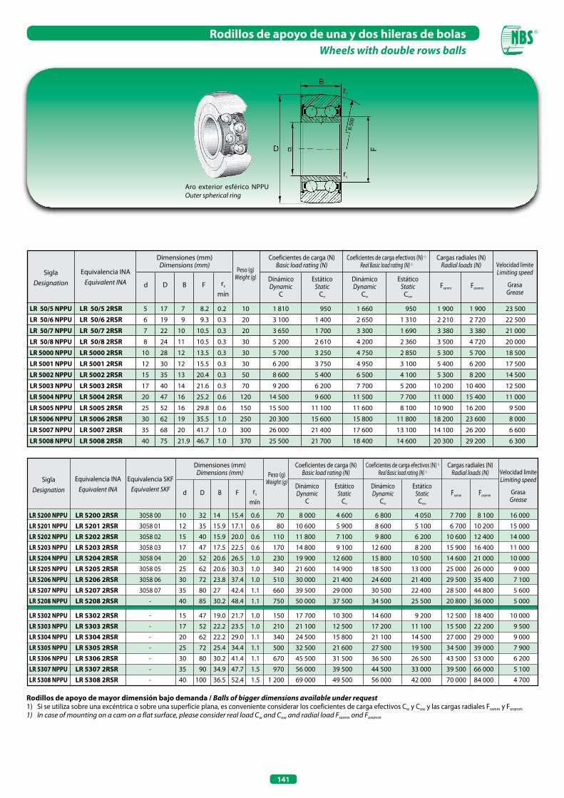
141
Rodillos de apoyo de una y dos hileras de bolas Wheels with double rows balls
Rodillos de apoyo de mayor dimensión bajo demanda / Balls of bigger dimensions available under request1) Si se utiliza sobre una excéntrica o sobre una superficie plana, es conveniente considerar los coeficientes de carga efectivos Cw y Cow y las cargas radiales Framm y Foramm
1) In case of mounting on a cam on a flat surface, please consider real load Cw and Cow and radial load Framm ond Foramm
SiglaDesignation
Equivalencia INAEquivalent INA
Dimensiones (mm)Dimensions (mm)
Coeficientes de carga (N)Basic load rating (N)
Cargas radiales (N)Radial loads (N)
d D B F rs
mín
DinámicoDynamic
C
EstáticoStatic
Co
Coeficientes de carga efectivos (N) 1)
Real Basic load rating (N) 1)
ForammFramm
DinámicoDynamic
Cw
EstáticoStatic
Cow
Aro exterior esférico NPPUOuter spherical ring
rs
rs
F
R-50
0
LR 50/5 2RSR
LR 50/6 2RSR
LR 50/7 2RSR
LR 50/8 2RSR
LR 5000 2RSR
LR 5001 2RSR
LR 5002 2RSR
LR 5003 2RSR
LR 5004 2RSR
LR 5005 2RSR
LR 5006 2RSR
LR 5007 2RSR
LR 5008 2RSR
5 17 7 8.2 0.2 10 1 810 950 1 660 950 1 900 1 900 23 500
6 19 9 9.3 0.3 20 3 100 1 400 2 650 1 310 2 210 2 720 22 500
7 22 10 10.5 0.3 20 3 650 1 700 3 300 1 690 3 380 3 380 21 000
8 24 11 10.5 0.3 30 5 200 2 610 4 200 2 360 3 500 4 720 20 000
10 28 12 13.5 0.3 30 5 700 3 250 4 750 2 850 5 300 5 700 18 500
12 30 12 15.5 0.3 30 6 200 3 750 4 950 3 100 5 400 6 200 17 500
15 35 13 20.4 0.3 50 8 600 5 400 6 500 4 100 5 300 8 200 14 500
17 40 14 21.6 0.3 70 9 200 6 200 7 700 5 200 10 200 10 400 12 500
20 47 16 25.2 0.6 120 14 500 9 600 11 500 7 700 11 000 15 400 11 000
25 52 16 29.8 0.6 150 15 500 11 100 11 600 8 100 10 900 16 200 9 500
30 62 19 35.5 1.0 250 20 300 15 600 15 800 11 800 18 200 23 600 8 000
35 68 20 41.7 1.0 300 26 000 21 400 17 600 13 100 14 100 26 200 6 600
40 75 21.9 46.7 1.0 370 25 500 21 700 18 400 14 600 20 300 29 200 6 300
SiglaDesignation
Equivalencia INAEquivalent INA
Equivalencia SKFEquivalent SKF
Dimensiones (mm)Dimensions (mm)
Coeficientes de carga (N)Basic load rating (N)
Cargas radiales (N)Radial loads (N)
d D B F rs
mín
DinámicoDynamic
C
EstáticoStatic
Co
Coeficientes de carga efectivos (N) 1) Real Basic load rating (N) 1)
ForammFramm
DinámicoDynamic
Cw
EstáticoStatic
Cow
10 32 14 15.4 0.6 70 8 000 4 600 6 800 4 050 7 700 8 100 16 000
12 35 15.9 17.1 0.6 80 10 600 5 900 8 600 5 100 6 700 10 200 15 000
15 40 15.9 20.0 0.6 110 11 800 7 100 9 800 6 200 10 600 12 400 14 000
17 47 17.5 22.5 0.6 170 14 800 9 100 12 600 8 200 15 900 16 400 11 000
20 52 20.6 26.5 1.0 230 19 900 12 600 15 800 10 500 14 600 21 000 10 000
25 62 20.6 30.3 1.0 340 21 600 14 900 18 500 13 000 25 000 26 000 9 000
30 72 23.8 37.4 1.0 510 30 000 21 400 24 600 21 400 29 500 35 400 7 100
35 80 27 42.4 1.1 660 39 500 29 000 30 500 22 400 28 500 44 800 5 600
40 85 30.2 48.4 1.1 750 50 000 37 500 34 500 25 500 20 800 36 000 5 000 15 47 19.0 21.7 1.0 150 17 700 10 300 14 600 9 200 12 500 18 400 10 000
17 52 22.2 23.5 1.0 210 21 100 12 500 17 200 11 100 15 500 22 200 9 500
20 62 22.2 29.0 1.1 340 24 500 15 800 21 100 14 500 27 000 29 000 9 000
25 72 25.4 34.4 1.1 500 32 500 21 600 27 500 19 500 34 500 39 000 7 900
30 80 30.2 41.4 1.1 670 45 500 31 500 36 500 26 500 43 500 53 000 6 200
35 90 34.9 47.7 1.5 970 56 000 39 500 44 500 33 000 39 500 66 000 5 100
40 100 36.5 52.4 1.5 1 200 69 000 49 500 56 000 42 000 70 000 84 000 4 700
LR 5200 NPPU LR 5201 NPPU LR 5202 NPPU LR 5203 NPPU LR 5204 NPPU LR 5205 NPPU LR 5206 NPPU LR 5207 NPPU LR 5208 NPPU LR 5302 NPPU LR 5303 NPPU LR 5304 NPPU LR 5305 NPPU LR 5306 NPPU LR 5307 NPPU LR 5308 NPPU
LR 5200 2RSR LR 5201 2RSR LR 5202 2RSR LR 5203 2RSR LR 5204 2RSR LR 5205 2RSR LR 5206 2RSR LR 5207 2RSR LR 5208 2RSR LR 5302 2RSR LR 5303 2RSR LR 5304 2RSR LR 5305 2RSR LR 5306 2RSR LR 5307 2RSR LR 5308 2RSR
3058 00
3058 01
3058 02
3058 03
3058 04
3058 05
3058 06
3058 07
-
-
-
-
-
-
-
-
Peso (g)Weight (g)
Peso (g)Weight (g)
LR 50/5 NPPU
LR 50/6 NPPU
LR 50/7 NPPU
LR 50/8 NPPU
LR 5000 NPPU
LR 5001 NPPU
LR 5002 NPPU
LR 5003 NPPU
LR 5004 NPPU
LR 5005 NPPU
LR 5006 NPPU
LR 5007 NPPU
LR 5008 NPPU
Velocidad limiteLimiting speed
GrasaGrease
Velocidad limiteLimiting speed
GrasaGrease

142
Rodillos de apoyo de una y dos hileras de bolas Wheels with double rows balls
Aro exterior cilíndrico KDDOuter cylindrical ring
Aro exterior esférico KDDUOuter spherical ring
rs
rs
R-50
0
SiglaDesignation
Equivalencia INAEquivalent INA
Equivalencia SKFEquivalent SKF
Dimensiones (mm)Dimensions (mm)
Coeficientes de carga (N)Basic load rating (N)
Cargas radiales (N)Radial loads (N)
d D B F rs
mín
DinámicoDynamic
C
EstáticoStatic
Co
Coeficientes de carga efectivos (N) 1) Real Basic load rating (N) 1)
ForammFramm
DinámicoDynamic
Cw
EstáticoStatic
Cow
10 32 14 15.4 0.6 70 8 000 4 600 6 800 4 050 7 700 8 100 16 000
12 35 15.9 17.1 0.6 80 10 600 5 900 8 600 5 100 6 700 10 200 15 000
15 40 15.9 20.0 0.6 110 11 800 7 100 9 800 6 200 10 600 12 400 14 000
17 47 17.5 22.5 0.6 170 14 800 9 100 12 600 8 200 15 900 16 400 11 000
20 52 20.6 26.5 1.0 230 19 900 12 600 15 800 10 500 14 600 21 000 10 000
25 62 20.6 30.3 1.0 340 21 600 14 900 18 500 13 000 25 000 26 000 9 000
30 72 23.8 37.4 1.0 510 30 000 21 400 24 600 21 400 29 500 35 400 7 100
35 80 27 42.4 1.1 660 39 500 29 000 30 500 22 400 28 500 44 800 5 600
40 85 30.2 48.4 1.1 750 50 000 37 500 34 500 25 500 20 800 36 000 5 000
LR 5200 KDD LR 5201 KDD LR 5202 KDD LR 5203 KDD LR 5204 KDD LR 5205 KDD LR 5206 KDD LR 5207 KDD LR 5208 KDD
LR 5200 KDDU LR 5201 KDDU LR 5202 KDDU LR 5203 KDDU LR 5204 KDDU LR 5205 KDDU LR 5206 KDDU LR 5207 KDDU LR 5208 KDDU
LR 5200 - x- 2Z LR 5201 - x- 2Z LR 5202 - x- 2Z LR 5203 - x- 2Z LR 5204 - x- 2Z LR 5205 - x- 2Z LR 5206 - x- 2Z LR 5207 - x- 2Z LR 5208 - x- 2Z
LR 5200 2Z LR 5201 2Z LR 5202 2Z LR 5203 2Z LR 5204 2Z LR 5205 2Z LR 5206 2Z LR 5207 2Z LR 5208 2Z
-
3057 01
3057 02
3057 03
3057 04
3057 05
3057 06
3057 07
-
3058 00
3058 01
3058 02
3058 03
3058 04
3058 05
3058 06
3058 07
-
SiglaDesignation
Equivalencia INAEquivalent INA
Dimensiones (mm)Dimensions (mm)
Coeficientes de carga (N)Basic load rating (N)
Cargas radiales (N)Radial loads (N)
d D B F rs
mín
DinámicoDynamic
C
EstáticoStatic
Co
Coeficientes de carga efectivos (N) 1)
Real Basic load rating (N) 1)
ForammFramm
DinámicoDynamic
Cw
EstáticoStatic
Cow
LR 5304 2Z LR 5305 2Z LR 5306 2Z LR 5307 2Z LR 5308 2Z
20 62 22.2 29.0 1.1 340 24 500 15 800 21 100 14 500 27 000 29 000 9 000
25 72 25.4 34.4 1.1 500 32 500 21 600 27 500 19 500 34 500 39 000 7 900
30 80 30.2 41.4 1.1 670 45 500 31 500 36 500 26 500 43 500 53 000 6 200
35 90 34.9 47.7 1.5 970 56 000 39 500 44 500 33 000 39 500 66 000 5 100
40 100 36.5 52.4 1.5 1 200 69 000 49 500 56 000 42 000 70 000 84 000 4 700
Rodillos de apoyo de mayor dimensión bajo demanda / Balls of bigger dimensions available under request1) Si se utiliza sobre una excéntrica o sobre una superficie plana, es conveniente considerar los coeficientes de carga efectivos Cw y Cow y las cargas radiales Framm y Foramm
1) In case of mounting on a cam on a flat surface, please consider real load Cw and Cow and radial load Framm ond Foramm
F
Peso (g)Weight (g)
Peso (g)Weight (g)
LR 5304 KDDU LR 5305 KDDU LR 5306 KDDU LR 5307 KDDU LR 5308 KDDU
Velocidad limiteLimiting speed
GrasaGrease
Velocidad limiteLimiting speed
GrasaGrease
RODAMIENTOS RÍGIDOS DE AGUJAS y AxIALES DE RODILLOS CILÍNDRICOSRADIAL NEEDLE ROLLER BEARINGS AND
AXIAL CYLINDRICAL NEEDLE ROLLER BEARINGS


145
Rodamientos rígidos de agujas y axiales de rodillos cilíndricosRadial needle roller bearings and axial cylindrical needle roller bearings
Son particularmente idóneos para aplicaciones que necesitan un posicionamiento axial muy preciso y que deben soportar elevadas cargas. Los rodamientos rígidos de agujas ZARN..L están constituidos por un rodamiento radial de agujas con jaula dotado de aro exterior de gran espesor, cuyas caras laterales son usadas como camino de rodadura de dos arandelas de empuje de agujas o de rodillos. El aro interior del rodamiento radial, sujetado lateralmente entre las arandelas de empuje, funciona como separador para el rodamiento axial.El mismo concepto vale para los rodamientos ..L, pero la principal diferencia es que estos rodamientos, contrariamente a lo que sucede en los ZARN..L, tienen el aro exterior del rodamiento radial más alto, en modo tal de formar una brida con orificios para la fijación. Además estos rodamientos están destinados a aplicaciones con bajas velocidades y cargas menos elevadas.Bajo demanda estos rodamientos pueden suministrarse con obturaciones especiales que sirven para proteger contra eventuales agentes externos. Es necesario prestar mucha atención cuando se realiza el montaje, ya que estos rodamientos se deberán siempre aplicar sobre partes bien rígidas. El aro exterior debe quedar bloqueado contra una superficie de tope para evitar cualquier tipo de desplazamiento axial en fase de carga.Los rodamientos ZARF..L se fijan en la máquina con tornillos aplicados en los orificios previstos en el aro exterior. La lubricación se podrá efectuar desde tres lados distintos,ya que la conjunción de los tres conductos permite una lubricación global. Los rodamientos de la serie ZARF y ZARNse suministran con juego radial C2, la precisión dimensional y constructiva corresponde a las clases P6 y P4 para la parte radial y la parte axial.
Tipologías de los rodamientos rígidos de agujas y axiales de rodillos cilíndricosRadial needle roller bearings and axial cylindrical needle roller bearings types
ZARF Rodamieno radial de agujas, combinado con rodamientos axiales de rodillos cilíndricos con arandela interme-dia (serie ligera y pesada). Aro exterior con orificios para el montaje con tornillos.
Needle roller/axial cylindrical roller bearing, double direction, outer ring suitable for flange mounting, with axial preload facility (light and heavy series). Outer ring suitable for flange mounting.
ZARF..L Rodamieno radial de agujas, combinado con rodamientos axiales de rodillos cilíndricos como la serie ZARF, con una de las dos arandelas para eje extensa y perfilada. Aro exterior con orificios para el montaje con tornillos.
Needle roller/axial cylindrical roller bearing as ZARF, with stepped, extended shaft washer on one side. Outer ring suitable for flange mounting.
ZARN Rodamiento radial de agujas y axial de rodillos cilíndricos de doble efecto, precargable axialmente (serie ligera y pesada) Radial needle roller bearings and axial cylindrical needle roller bearings, double direction, with axial preload facility
(light and heavy series)
ZARN..L Rodamieno radial de agujas, combinado con rodamientos axiales de rodillos cilíndricos como la serie ZARN, con una de las dos arandelas para eje extensa y perfilada.
Needle roller/axial cylindrical roller bearing as ZARN, with stepped, extended shaft washer on one side
Tipo-Type Características-Characteristics
These needle roller bearings are particularly suitable for applications requiring ability to stand heavy loads and a very accurate axial placing.Radial needle roller bearings ZARN..L consist in caged radial needle bearing supplied with an outer ring having a big thickness, its lateral surfaces are used as raceways for two thrust needle bearings or roller bearings; the inner ring of radial needle roller bearing is holded sideways between the ring of the thrust bearing and it works as a spacer for the axial bearing.A ZARF..L bearing has the same characteristic of a ZARN..L type, but it’s different from it because these bearings have the outer ring of radial bearing that is higher, creating in this way a flange provided with fixation holes.They are suitable for applications requiring low speeds and lighter loads.Under request for these needle roller bearings special oil seals can be supplied : their special duty is to protect them from external factors.It is very important to carefully follow assembling operations, as these bearings have to be mounted on very rigid parts: the outer ring has to be locked against one housing step, avoiding in this way any kind of axial movement while loading.Concerning a ZARF..L bearing, it is mounted on machinery by some screw inside the holes existing on the outer ring.Lubrication can be effectued from the three different sides, as the union of three galleries enables a total lubrication.ZARN and ZARF are supplied with C2 radial clearance, P6 and P4 are their dimensional and shaping tolerances concerning radial and axial part.
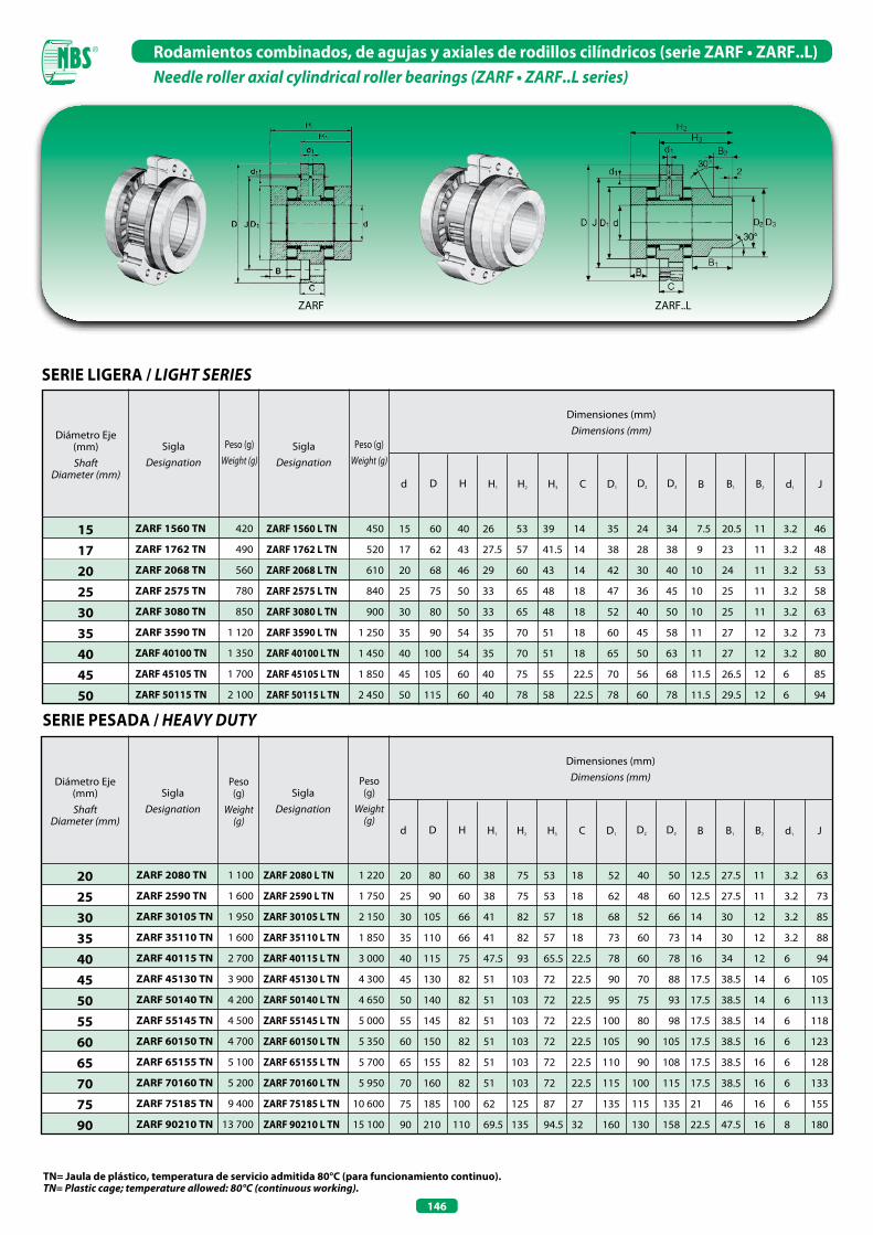
146
Rodamientos combinados, de agujas y axiales de rodillos cilíndricos (serie ZARF • ZARF..L)Needle roller axial cylindrical roller bearings (ZARF • ZARF..L series)
SERIE LIGERA / LIGHT SERIES
SERIE PESADA / HEAVY DUTY
TN= Jaula de plástico, temperatura de servicio admitida 80°C (para funcionamiento continuo).TN= Plastic cage; temperature allowed: 80°C (continuous working).
Dimensiones (mm)Dimensions (mm)Diámetro Eje
(mm) Shaft
Diameter (mm)Hd D H1 H2 H3 C D1 D2 D3 B1 B2
SiglaDesignation
Peso (g)Weight (g)
Peso (g)Weight (g)
SiglaDesignation
B d1 J
ZARF 1560 TN
ZARF 1762 TN
ZARF 2068 TN
ZARF 2575 TN
ZARF 3080 TN
ZARF 3590 TN
ZARF 40100 TN
ZARF 45105 TN
ZARF 50115 TN
420
490
560
780
850
1 120
1 350
1 700
2 100
450
520
610
840
900
1 250
1 450
1 850
2 450
ZARF 1560 L TN
ZARF 1762 L TN
ZARF 2068 L TN
ZARF 2575 L TN
ZARF 3080 L TN
ZARF 3590 L TN
ZARF 40100 L TN
ZARF 45105 L TN
ZARF 50115 L TN
15 60 40 26 53 39 14 35 24 34 7.5 20.5 11 3.2 46
17 62 43 27.5 57 41.5 14 38 28 38 9 23 11 3.2 48
20 68 46 29 60 43 14 42 30 40 10 24 11 3.2 53
25 75 50 33 65 48 18 47 36 45 10 25 11 3.2 58
30 80 50 33 65 48 18 52 40 50 10 25 11 3.2 63
35 90 54 35 70 51 18 60 45 58 11 27 12 3.2 73
40 100 54 35 70 51 18 65 50 63 11 27 12 3.2 80
45 105 60 40 75 55 22.5 70 56 68 11.5 26.5 12 6 85
50 115 60 40 78 58 22.5 78 60 78 11.5 29.5 12 6 94
Dimensiones (mm)Dimensions (mm)Diámetro Eje
(mm) Shaft
Diameter (mm)Hd D H1 H2 H3 C D1 D2 D3 B1 B2
SiglaDesignation
Peso(g)
Weight(g)
Peso(g)
Weight(g)
SiglaDesignation
B d1 J
ZARF 2080 TN
ZARF 2590 TN
ZARF 30105 TN
ZARF 35110 TN
ZARF 40115 TN
ZARF 45130 TN
ZARF 50140 TN
ZARF 55145 TN
ZARF 60150 TN
ZARF 65155 TN
ZARF 70160 TN
ZARF 75185 TN
ZARF 90210 TN
1 100
1 600
1 950
1 600
2 700
3 900
4 200
4 500
4 700
5 100
5 200
9 400
13 700
ZARF 2080 L TN
ZARF 2590 L TN
ZARF 30105 L TN
ZARF 35110 L TN
ZARF 40115 L TN
ZARF 45130 L TN
ZARF 50140 L TN
ZARF 55145 L TN
ZARF 60150 L TN
ZARF 65155 L TN
ZARF 70160 L TN
ZARF 75185 L TN
ZARF 90210 L TN
1 220
1 750
2 150
1 850
3 000
4 300
4 650
5 000
5 350
5 700
5 950
10 600
15 100
20 80 60 38 75 53 18 52 40 50 12.5 27.5 11 3.2 63
25 90 60 38 75 53 18 62 48 60 12.5 27.5 11 3.2 73
30 105 66 41 82 57 18 68 52 66 14 30 12 3.2 85
35 110 66 41 82 57 18 73 60 73 14 30 12 3.2 88
40 115 75 47.5 93 65.5 22.5 78 60 78 16 34 12 6 94
45 130 82 51 103 72 22.5 90 70 88 17.5 38.5 14 6 105
50 140 82 51 103 72 22.5 95 75 93 17.5 38.5 14 6 113
55 145 82 51 103 72 22.5 100 80 98 17.5 38.5 14 6 118
60 150 82 51 103 72 22.5 105 90 105 17.5 38.5 16 6 123
65 155 82 51 103 72 22.5 110 90 108 17.5 38.5 16 6 128
70 160 82 51 103 72 22.5 115 100 115 17.5 38.5 16 6 133
75 185 100 62 125 87 27 135 115 135 21 46 16 6 155
90 210 110 69.5 135 94.5 32 160 130 158 22.5 47.5 16 8 180
ZARF ZARF..L
151720253035404550
20253035404550556065707590

147
Rodamientos combinados, de agujas y axiales de rodillos cilíndricos (serie ZARF • ZARF..L)Needle roller axial cylindrical roller bearings (ZARF • ZARF..L series)
1) Par de apriete para tornillos de fijación según las indicaciones del fabricante, los tornillos conformes con las normas DIN no forman parte del suministro. Tightening for fixation screws, as per manufacturer’s indications. Screws, in accordance with DIN are not included in this sales program.2) Numero de giros límite para lubricación con aceite con suficiente aceite de enfriamiento. Number of allowed revolutions with an oil lubrication, with enough cooling oil.
TuercaLocknut
Tornillos de fijación 1)
Fixing Screws
GrasaGrease MRL
NmNº giros máxmax rpm
Dinámico CDynamic C
Dinámico CDynamic C
Estático Co
Static Co
Estático Co
Static Co
Axial / Axial Radial / RadialRoscadoThread
CantidadQuantity
Coeficiente de carga (N)Basic Load Rating (N)
Aceite 2)
Oil
N/µm Nm/mrad
CaL CkL
Par de fricción Bearing
FrictionalTorque
Rigidez axialAxial
Rigidity
Nm
MARoscadoThread
M6 6
M6 6
M6 8
M6 8
M6 12
M6 12
M8 8
M8 8
M8 12
23 600 50 350 12 000 16 500
24 700 54 150 13 300 18 900
32 500 72 200 14 100 21 280
33 700 81 700 21 470 34 200
37 000 95 950 23 100 39 400
53 200 140 600 24 700 44 650
56 000 154 850 26 100 50 350
57 950 168 150 36 100 70 300
85 500 285 000 38 000 77 900
8 000 2 100 0.32 1 260
7 400 2 000 0.38 1 400
6 600 1 900 0.41 1 600
5 700 1 800 0.50 1 700
5 200 1 700 0.55 2 000
4 560 1 600 0.79 2 300
4 180 1 500 0.88 2 500
3 800 1 400 1.00 2 800
3 400 1 150 1.90 3 700
100 M15x1 10
130 M17x1 12
190 M20x1.5 18
300 M25x1.5 25
420 M30x1.5 32
640 M35x1.5 42
1 000 M40x1.5 55
1 240 M45x1.5 65
2 370 M50x1.5 85
Velocidad limiteLimiting Speed
Rigidez angularTilting
Rigidity
TuercaLocknut
Tornillos de fijación 1)
Fixing Screws
GrasaGrease MRL
NmNº giros máxmax rpm
Dinámico CDynamic C
Dinámico CDynamic C
Estático Co
Static Co
Estático Co
Static Co
Axial / Axial Radial / RadialRoscadoThread
CantidadQuantity
Coeficiente de carga (N)Basic Load Rating (N)
Aceite 2)
Oil
N/µm Nm/mrad
CaL CkL
Par de fricción Bearing
FrictionalTorque
Rigidez axialAxial
Rigidity
Nm
MARoscadoThread
Velocidad limiteLimiting Speed
Rigidez angularTilting
Rigidity
M6 12
M6 12
M8 12
M8 12
M8 12
M8 12
M10 12
M10 12
M10 12
M10 12
M10 12
M12 12
M12 16
64 000 141 000 22 600 36 000
80 000 199 000 24 300 41 500
107 000 265 000 26 000 47 000
105 000 265 000 27 500 53 000
117 000 315 000 38 000 74 000
154 000 405 000 40 000 82 000
172 000 480 000 42 000 90 000
177 000 500 000 44 000 98 000
187 000 550 000 44 500 92 000
172 000 500 000 54 000 104 000
201 000 630 000 56 000 119 000
290 000 890 000 72 000 132 000
325 000 1 030 000 98 000 210 000
6 000 1 500 1.3 2 300
4 900 1 400 1.6 3 000
4 400 1 300 2.1 3 300
4 000 1 250 2.3 2 500
3 700 1 200 2.5 3 800
3 300 1 150 3.5 4 000
3 100 1 100 3.8 4 600
2 900 1 000 4 4 900
2 700 950 4.2 5 300
2 600 900 4 4 800
2 400 800 4.8 5 800
2 100 700 8 6 600
1 800 700 10.5 7 700
400 M20x1 38
800 M25x1.5 55
1 100 M30x1.5 75
1 300 M35x1.5 100
1 800 M40x1.5 120
2 100 M45x1.5 150
2 900 M50X1.5 180
3 600 M55X2 220
4 300 M60X2 250
4 000 M65X2 270
6 000 M70X2 330
8 500 M75X2 580
14 500 M90X2 960
ZARF ZARF..L
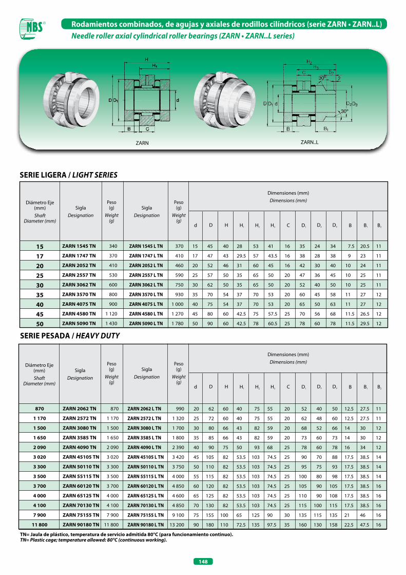
148
Rodamientos combinados, de agujas y axiales de rodillos cilíndricos (serie ZARN • ZARN..L)Needle roller axial cylindrical roller bearings (ZARN • ZARN..L series)
Dimensiones (mm)Dimensions (mm)
ZARN ZARN..L
Dimensiones (mm)Dimensions (mm)Diámetro Eje
(mm) Shaft
Diameter (mm)Hd D H1 H2 H3 C D1 D2 D3 B1 B2
SiglaDesignation
Peso(g)
Weight(g)
Peso(g)
Weight(g)
SiglaDesignation
B
340
370
410
530
600
800
900
1 120
1 430
151720253035404550
ZARN 1545 TN
ZARN 1747 TN
ZARN 2052 TN
ZARN 2557 TN
ZARN 3062 TN
ZARN 3570 TN
ZARN 4075 TN
ZARN 4580 TN
ZARN 5090 TN
ZARN 1545 L TN
ZARN 1747 L TN
ZARN 2052 L TN
ZARN 2557 L TN
ZARN 3062 L TN
ZARN 3570 L TN
ZARN 4075 L TN
ZARN 4580 L TN
ZARN 5090 L TN
370
410
460
590
750
930
1 000
1 270
1 780
15 45 40 28 53 41 16 35 24 34 7.5 20.5 11
17 47 43 29.5 57 43.5 16 38 28 38 9 23 11
20 52 46 31 60 45 16 42 30 40 10 24 11
25 57 50 35 65 50 20 47 36 45 10 25 11
30 62 50 35 65 50 20 52 40 50 10 25 11
35 70 54 37 70 53 20 60 45 58 11 27 12
40 75 54 37 70 53 20 65 50 63 11 27 12
45 80 60 42.5 75 57.5 25 70 56 68 11.5 26.5 12
50 90 60 42.5 78 60.5 25 78 60 78 11.5 29.5 12
SERIE LIGERA / LIGHT SERIES
SERIE PESADA / HEAVY DUTY
Diámetro Eje (mm) Shaft
Diameter (mm)
SiglaDesignation
ZARN 2062 TN
ZARN 2572 TN
ZARN 3080 TN
ZARN 3585 TN
ZARN 4090 TN
ZARN 45105 TN
ZARN 50110 TN
ZARN 55115 TN
ZARN 60120 TN
ZARN 65125 TN
ZARN 70130 TN
ZARN 75155 TN
ZARN 90180 TN
870
1 170
1 500
1 650
2 090
3 020
3 300
3 500
3 700
4 000
4 100
7 900
11 800
870
1 170
1 500
1 650
2 090
3 020
3 300
3 500
3 700
4 000
4 100
7 900
11 800
ZARN 2062 L TN
ZARN 2572 L TN
ZARN 3080 L TN
ZARN 3585 L TN
ZARN 4090 L TN
ZARN 45105 L TN
ZARN 50110 L TN
ZARN 55115 L TN
ZARN 60120 L TN
ZARN 65125 L TN
ZARN 70130 L TN
ZARN 75155 L TN
ZARN 90180 L TN
990
1 320
1 700
1 800
2 390
3 420
3 750
4 000
4 850
4 600
4 850
9 100
13 200
20 62 60 40 75 55 20 52 40 50 12.5 27.5 11
25 72 60 40 75 55 20 62 48 60 12.5 27.5 11
30 80 66 43 82 59 20 68 52 66 14 30 12
35 85 66 43 82 59 20 73 60 73 14 30 12
40 90 75 50 93 68 25 78 60 78 16 34 12
45 105 82 53.5 103 74.5 25 90 70 88 17.5 38.5 14
50 110 82 53.5 103 74.5 25 95 75 93 17.5 38.5 14
55 115 82 53.5 103 74.5 25 100 80 98 17.5 38.5 14
60 120 82 53.5 103 74.5 25 105 90 105 17.5 38.5 16
65 125 82 53.5 103 74.5 25 110 90 108 17.5 38.5 16
70 130 82 53.5 103 74.5 25 115 100 115 17.5 38.5 16
75 155 100 65 125 90 30 135 115 135 21 46 16
90 180 110 72.5 135 97.5 35 160 130 158 22.5 47.5 16
TN= Jaula de plástico, temperatura de servicio admitida 80°C (para funcionamiento continuo).TN= Plastic cage; temperature allowed: 80°C (continuous working).
Hd D H1 H2 H3 C D1 D2 D3 B1 B2
Peso(g)
Weight(g)
Peso(g)
Weight(g)
SiglaDesignation
B
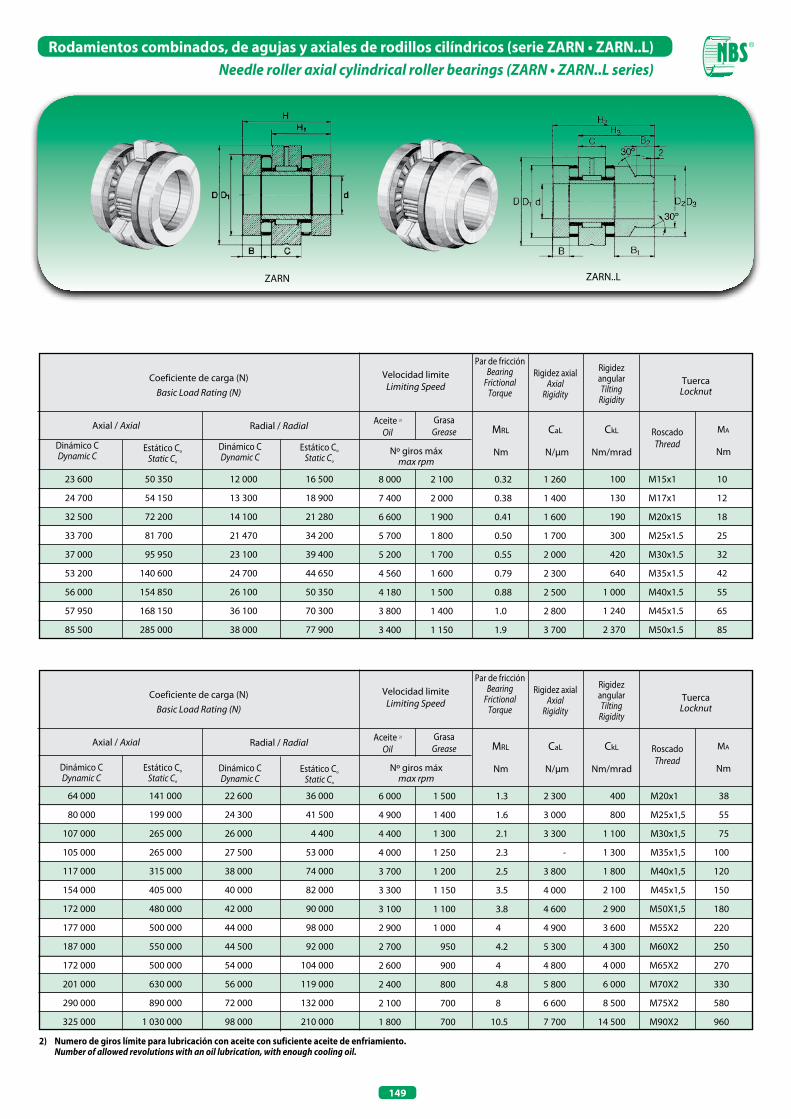
149
Rodamientos combinados, de agujas y axiales de rodillos cilíndricos (serie ZARN • ZARN..L)Needle roller axial cylindrical roller bearings (ZARN • ZARN..L series)
ZARN ZARN..L
TuercaLocknut
TuercaLocknut
GrasaGrease
GrasaGrease
MRL
MRL
Nm
Nm
Nº giros máxmax rpm
Nº giros máxmax rpm
Dinámico CDynamic C
Dinámico CDynamic C
Dinámico CDynamic C
Dinámico CDynamic C
Estático Co
Static Co
Estático Co
Static Co
Estático Co
Static Co
Estático Co
Static Co
Axial / Axial
Axial / Axial
Radial / Radial
Radial / Radial
Coeficiente de carga (N)Basic Load Rating (N)
Coeficiente de carga (N)Basic Load Rating (N)
Aceite 2)
Oil
Aceite 2)
Oil
N/µm
N/µm
Nm/mrad
Nm/mrad
CaL
CaL
CkL
CkL
Par de fricción Bearing
FrictionalTorque
Par de fricción Bearing
FrictionalTorque
Rigidez axialAxial
Rigidity
Rigidez axialAxial
Rigidity
Nm
Nm
MA
MA
RoscadoThread
RoscadoThread
Velocidad limiteLimiting Speed
Velocidad limiteLimiting Speed
Rigidez angularTilting
Rigidity
Rigidez angularTilting
Rigidity
8 000 2 100 0.32 1 260
7 400 2 000 0.38 1 400
6 600 1 900 0.41 1 600
5 700 1 800 0.50 1 700
5 200 1 700 0.55 2 000
4 560 1 600 0.79 2 300
4 180 1 500 0.88 2 500
3 800 1 400 1.0 2 800
3 400 1 150 1.9 3 700
6 000 1 500 1.3 2 300
4 900 1 400 1.6 3 000
4 400 1 300 2.1 3 300
4 000 1 250 2.3 -
3 700 1 200 2.5 3 800
3 300 1 150 3.5 4 000
3 100 1 100 3.8 4 600
2 900 1 000 4 4 900
2 700 950 4.2 5 300
2 600 900 4 4 800
2 400 800 4.8 5 800
2 100 700 8 6 600
1 800 700 10.5 7 700
100 M15x1 10
130 M17x1 12
190 M20x15 18
300 M25x1.5 25
420 M30x1.5 32
640 M35x1.5 42
1 000 M40x1.5 55
1 240 M45x1.5 65
2 370 M50x1.5 85
400 M20x1 38
800 M25x1,5 55
1 100 M30x1,5 75
1 300 M35x1,5 100
1 800 M40x1,5 120
2 100 M45x1,5 150
2 900 M50X1,5 180
3 600 M55X2 220
4 300 M60X2 250
4 000 M65X2 270
6 000 M70X2 330
8 500 M75X2 580
14 500 M90X2 960
2) Numero de giros límite para lubricación con aceite con suficiente aceite de enfriamiento. Number of allowed revolutions with an oil lubrication, with enough cooling oil.
23 600 50 350 12 000 16 500
24 700 54 150 13 300 18 900
32 500 72 200 14 100 21 280
33 700 81 700 21 470 34 200
37 000 95 950 23 100 39 400
53 200 140 600 24 700 44 650
56 000 154 850 26 100 50 350
57 950 168 150 36 100 70 300
85 500 285 000 38 000 77 900
64 000 141 000 22 600 36 000
80 000 199 000 24 300 41 500
107 000 265 000 26 000 4 400
105 000 265 000 27 500 53 000
117 000 315 000 38 000 74 000
154 000 405 000 40 000 82 000
172 000 480 000 42 000 90 000
177 000 500 000 44 000 98 000
187 000 550 000 44 500 92 000
172 000 500 000 54 000 104 000
201 000 630 000 56 000 119 000
290 000 890 000 72 000 132 000
325 000 1 030 000 98 000 210 000
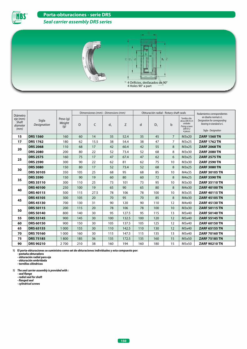
150
Diámetro eje (mm)
Shaftdiameter
(mm)
SiglaDesignation
Peso (g)Weight
(g)
Dimensiones (mm) - Dimensions (mm) Obturación radial - Rotary shaft seals Rodamientos correspondientes en diseño normal o L
Designation for correspondingbearing in standard or L
Sigla - Designation
D C d1 Z d D1 b
Tornillos cilín-dricos DIN 912 4
unidadesFixing screws
DIN 9124 pieces
15 DRS 1560 160 60 14 35 52.4 35 45 7 M3x20 ZARF 1560 TN17 DRS 1762 180 62 15.5 38 54.4 38 47 7 M3x25 ZARF 1762 TN
20DRS 2068 110 68 17 42 60.4 42 55 8 M3x25 ZARF 2068 TNDRS 2080 200 80 22 52 73.4 52 68 8 M3x30 ZARF 2080 TN
25DRS 2575 160 75 17 47 67.4 47 62 6 M3x25 ZARF 2575 TNDRS 2590 300 90 22 62 81 62 75 10 M3x30 ZARF 2590 TN
30DRS 3080 150 80 17 52 73.4 52 68 8 M3x25 ZARF 3080 TNDRS 30105 350 105 25 68 95 68 85 10 M4x35 ZARF 30105 TN
35DRS 3590 150 90 19 60 80 60 72 8 M4x25 ZARF 3590 TNDRS 35110 300 110 25 73 101 73 95 10 M3x30 ZARF 35110 TN
40DRS 40100 250 100 19 65 90 65 80 8 M4x30 ZARF 40100 TNDRS 40115 500 115 27.5 78 106 78 100 10 M3x35 ZARF 40115 TN
45DRS 45105 300 105 20 70 95 70 85 8 M4x30 ZARF 45105 TNDRS 45130 700 130 31 90 120 90 110 12 M4x40 ZARF 45130 TN
50DRS 50115 200 115 20 78 106 78 100 10 M3x30 ZARF 50115 TNDRS 50140 800 140 30 95 127.5 95 115 13 M5x40 ZARF 50140 TN
55 DRS 55145 900 145 30 100 132.5 100 120 12 M5x40 ZARF 55145 TN60 DRS 60150 900 150 30 105 137.5 105 125 12 M5x40 ZARF 60150 TN65 DRS 65155 1 000 155 30 110 142.5 110 130 12 M5x40 ZARF 65155 TN70 DRS 70160 1 000 160 30 115 147.5 115 135 13 M5x40 ZARF 70160 TN75 DRS 75185 1 800 185 36 135 172.5 135 160 15 M5x50 ZARF 75185 TN90 DRS 90210 2 700 210 38 160 194 160 180 15 M5x50 ZARF 90210 TN
Porta-obturaciones - serie DRSSeal carrier assembly DRS series
1) 4 Orificios, desfasados de 90° 4 Holes 90° a part
1) El porta-obturaciones se suministra como set de obturaciones individuales y esta compuesto por: - pestaña obturadora - obturación radial para eje - obturación embridada - tornillos cilíndricos
1) The seal carrier assembly is provided with : - seal flange - radial seal for shaft - flanged seal - cylindrical screws
RODAMIENTOS RÍGIDOS COMPLETAMENTE LLENOS DE RODILLOS CILINDRICOSCYLINDRICAL ROLLER BEARINGS, FULL COMPLEMENT ROLLER SET
152
Rodamientos rígidos completamente llenos de rodillos cilíndricosCylindrical roller bearings, full complement roller set
Los rodamientos rígidos completamente llenos de rodillos cilíndricos están compuestos por rodillos cilíndricos guíados en los bordes y aros exteriores e interiores macizos. Gracias al gran número de rodillos pueden garantizar coeficientes de carga dinámica y estática elevados. Estos particulares rodamientos resultan indicados para la absorción de cargas en sentido radial y se utilizan cuando existen espacios constructivos reducidos. Los rodamientos rígidos completamente llenos de rodillos cilíndricos, pueden ser suministrados en las siguientes tipologías: con rodamientos libres, de apoyo, fijos, de una y dos hileras. Estos últimos rodamientos de dos hileras presentan una ranura y unos agujeros de engrase en el aro exterior, además de las obturaciones. En la tabla de la página 94 se indican las principales características de los rodamientos rígidos completamente llenos de rodillos cilíndricos.
Full complement cylindrical roller bearings are formed by cylindrical rollers, guided on the edge, and by massive inner and outer rings.The great number of rollers can ensure high coefficients of dynamic and static loads.These bearings are particularly suitable where high radial loads and small working places are present.There are different types of full complement cylindricalroller bearings: non-located, semi-located, located, and single and double row. Double row bearings are provided with groove and lubrication holes on the outer ring, as well as seals. The table in page 94, shows the main characteristics of full complement roller bearings.
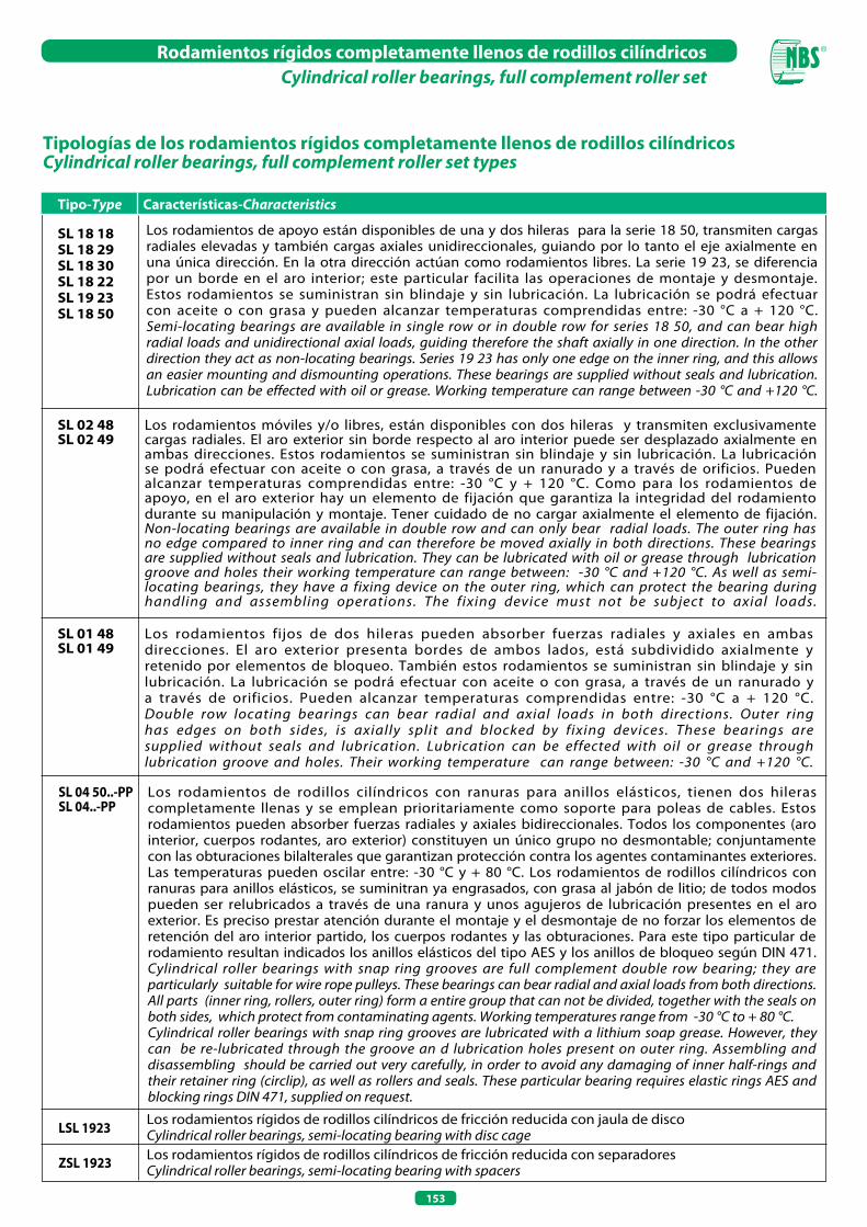
153
Rodamientos rígidos completamente llenos de rodillos cilíndricosCylindrical roller bearings, full complement roller set
SL 18 18SL 18 29 SL 18 30 SL 18 22SL 19 23SL 18 50
SL 02 48SL 02 49
SL 01 48SL 01 49
SL 04 50..-PPSL 04..-PP
LSL 1923
ZSL 1923
Tipo-Type Características-Characteristics
Tipologías de los rodamientos rígidos completamente llenos de rodillos cilíndricos Cylindrical roller bearings, full complement roller set types
Los rodamientos móviles y/o libres, están disponibles con dos hileras y transmiten exclusivamente cargas radiales. El aro exterior sin borde respecto al aro interior puede ser desplazado axialmente en ambas direcciones. Estos rodamientos se suministran sin blindaje y sin lubricación. La lubricación se podrá efectuar con aceite o con grasa, a través de un ranurado y a través de orificios. Pueden alcanzar temperaturas comprendidas entre: -30 °C y + 120 °C. Como para los rodamientos de apoyo, en el aro exterior hay un elemento de fijación que garantiza la integridad del rodamiento durante su manipulación y montaje. Tener cuidado de no cargar axialmente el elemento de fijación. Non-locating bearings are available in double row and can only bear radial loads. The outer ring has no edge compared to inner ring and can therefore be moved axially in both directions. These bearings are supplied without seals and lubrication. They can be lubricated with oil or grease through lubrication groove and holes their working temperature can range between: -30 °C and +120 °C. As well as semi-locating bearings, they have a fixing device on the outer ring, which can protect the bearing during handling and assembling operations. The fixing device must not be subject to axial loads.
Los rodamientos fijos de dos hileras pueden absorber fuerzas radiales y axiales en ambas direcciones. El aro exterior presenta bordes de ambos lados, está subdividido axialmente y retenido por elementos de bloqueo. También estos rodamientos se suministran sin blindaje y sin lubricación. La lubricación se podrá efectuar con aceite o con grasa, a través de un ranurado y a través de orificios. Pueden alcanzar temperaturas comprendidas entre: -30 °C a + 120 °C.Double row locating bearings can bear radial and axial loads in both directions. Outer ring has edges on both sides, is axially split and blocked by fixing devices. These bearings are supplied without seals and lubrication. Lubrication can be effected with oil or grease through lubrication groove and holes. Their working temperature can range between: -30 °C and +120 °C.
Los rodamientos de rodillos cilíndricos con ranuras para anillos elásticos, tienen dos hileras completamente llenas y se emplean prioritariamente como soporte para poleas de cables. Estos rodamientos pueden absorber fuerzas radiales y axiales bidireccionales. Todos los componentes (aro interior, cuerpos rodantes, aro exterior) constituyen un único grupo no desmontable; conjuntamente con las obturaciones bilalterales que garantizan protección contra los agentes contaminantes exteriores. Las temperaturas pueden oscilar entre: -30 °C y + 80 °C. Los rodamientos de rodillos cilíndricos con ranuras para anillos elásticos, se suminitran ya engrasados, con grasa al jabón de litio; de todos modos pueden ser relubricados a través de una ranura y unos agujeros de lubricación presentes en el aro exterior. Es preciso prestar atención durante el montaje y el desmontaje de no forzar los elementos de retención del aro interior partido, los cuerpos rodantes y las obturaciones. Para este tipo particular de rodamiento resultan indicados los anillos elásticos del tipo AES y los anillos de bloqueo según DIN 471.Cylindrical roller bearings with snap ring grooves are full complement double row bearing; they are particularly suitable for wire rope pulleys. These bearings can bear radial and axial loads from both directions. All parts (inner ring, rollers, outer ring) form a entire group that can not be divided, together with the seals on both sides, which protect from contaminating agents. Working temperatures range from -30 °C to + 80 °C.Cylindrical roller bearings with snap ring grooves are lubricated with a lithium soap grease. However, they can be re-lubricated through the groove an d lubrication holes present on outer ring. Assembling and disassembling should be carried out very carefully, in order to avoid any damaging of inner half-rings and their retainer ring (circlip), as well as rollers and seals. These particular bearing requires elastic rings AES and blocking rings DIN 471, supplied on request.
Los rodamientos de apoyo están disponibles de una y dos hileras para la serie 18 50, transmiten cargas radiales elevadas y también cargas axiales unidireccionales, guiando por lo tanto el eje axialmente en una única dirección. En la otra dirección actúan como rodamientos libres. La serie 19 23, se diferencia por un borde en el aro interior; este particular facilita las operaciones de montaje y desmontaje. Estos rodamientos se suministran sin blindaje y sin lubricación. La lubricación se podrá efectuar con aceite o con grasa y pueden alcanzar temperaturas comprendidas entre: -30 °C a + 120 °C.Semi-locating bearings are available in single row or in double row for series 18 50, and can bear high radial loads and unidirectional axial loads, guiding therefore the shaft axially in one direction. In the other direction they act as non-locating bearings. Series 19 23 has only one edge on the inner ring, and this allows an easier mounting and dismounting operations. These bearings are supplied without seals and lubrication. Lubrication can be effected with oil or grease. Working temperature can range between -30 °C and +120 °C.
Los rodamientos rígidos de rodillos cilíndricos de fricción reducida con jaula de discoCylindrical roller bearings, semi-locating bearing with disc cageLos rodamientos rígidos de rodillos cilíndricos de fricción reducida con separadoresCylindrical roller bearings, semi-locating bearing with spacers

154
Rodamientos rígidos completamente llenos de rodillos cilíndricos, de una hilera, rodamientos de apoyoCylindrical roller bearings, full complement roller set, single row, semi-locating bearings
SL1923 Desplazamiento axial «s»Axial displacement distance «s»
SL1829, SL1830, SL1822
20
25
30
35
40
45
50
55
60
65
70
Diámetro Eje (mm) Shaft
Diameter (mm)
SiglaDesignation
Peso (g)Weight (g)
Dimensiones (mm)Dimensions (mm)
Dimensiones de montaje (mm)Mounting dimensions (mm)
Coeficientes de carga (N)Basic Load Rating (N)
Dinámico CDynamic C
Estático C0
Static C0
D B s F
Velocidad limite
Limiting Speedd1
≈
D1
≈
Ed
SL183004SL182204SL183005SL182205SL192305SL183006SL182206SL192306SL183007SL182207SL192307SL183008SL182208SL192308SL183009SL182209SL192309SL183010SL182210SL192310SL183011SL182211SL192311SL182912SL183012SL182212SL192312SL182913SL183013SL182213SL192313SL182914SL183014SL182214SL192314
110
160
120
180
370
200
300
560
260
440
740
310
550
1 010
400
590
1 370
430
640
1 810
640
870
2 280
290
690
1 180
2 880
310
730
1 570
3 520
490
1 020
1 660
4 330
20 42 16 1.5
20 47 18 1
25 47 16 1.5
25 52 18 1
25 62 24 2
30 55 19 2
30 62 20 1
30 72 27 2
35 62 20 2
35 72 23 1
35 80 31 2
40 68 21 2
40 80 23 1
40 90 33 2
45 75 23 2
45 85 23 1
45 100 36 3
50 80 23 2
50 90 23 1
50 110 40 3
55 90 26 2
55 100 25 1
55 120 43 3
60 85 16 1
60 95 26 2
60 110 28 1.5
60 130 46 3
65 90 16 1
65 100 26 2
65 120 31 1.5
65 140 48 3.5
70 100 19 1
70 110 30 3
70 125 31 1.5
70 150 51 3.5
– 28.8 32.8 36.81
– 30.3 36.9 41.47
– 34.6 38.5 42.51
– 35.3 41.9 46.52
31.72 36.7 47.5 –
– 40 45.4 49.6
– 42 50.6 55.19
38.3 43.5 56 –
– 44.9 51.3 55.52
– 47 59.3 63.97
44.68 50.7 65.8 –
– 50.5 57.1 61.74
– 54 66.3 70.94
51.12 57.5 75.2 –
– 55.3 62.2 66.85
– 57.5 69.8 74.43
56.1 62.5 80.3 –
– 59.1 67.7 72.33
– 64.4 76.7 81.4
60.72 68.3 89.7 –
– 68.5 78.8 83.54
– 70 84.1 88.81
67.11 75.5 99.3 –
– 69 74.4 78.55
– 71.7 82.1 86.74
– 76.8 93.9 99.17
73.62 82 105.8 –
– 75.7 81 85.24
– 78.1 88.4 93.09
– 82.3 100.7 106.25
80.69 90 116.5 –
– 81.2 87.8 92.31
– 81.5 95.6 100.28
– 87 105.2 111.45
84.14 93.5 121.6 –
30 500 26 500
45 500 37 500
35 000 32 500
51 000 45 000
73 000 60 000
45 000 43 000
70 000 65 000
100 000 88 000
55 000 55 000
88 000 79 000
126 000 112 000
66 000 68 000
97 000 93 000
170 000 156 000
70 000 76 000
101 000 99 000
181 000 169 000
88 000 96 000
109 000 113 000
232 000 219 000
120 000 136 000
140 000 150 000
270 000 255 000
63 000 78 000
123 000 145 000
169 000 180 000
285 000 280 000
67 000 86 000
130 000 159 000
198 000 214 000
350 000 355 000
88 000 114 000
153 000 176 000
184 000 227 000
385 000 390 000
10 500
9 700
9 000
8 400
7 400
7 600
7 000
6 400
6 700
6 100
5 600
6 000
5 400
5 000
5 400
5 000
4 450
5 000
4 650
4 050
4 450
4 200
3 700
4 450
4 200
3 800
3 400
4 200
3 950
3 500
3 150
3 800
3 600
3 300
2 950

155
Rodamientos rígidos completamente llenos de rodillos cilíndricos, de una hilera, rodamientos de apoyoCylindrical roller bearings, full complement roller set, single row, semi-locating bearings
Peso (g)Weight (g)
Dimensiones (mm)Dimensions (mm)
Dimensiones de montaje (mm)Mounting dimensions (mm)
Coeficientes de carga (N)Basic Load Rating (N)
Dinámico CDynamic C
Estático C0
Static C0
D B s F
Velocidad limite
Limiting Speedd1
≈
D1
≈
Ed
SL182915
SL183015
SL182215
SL192315
SL182916
SL183016
SL182216
SL192316
SL182917
SL183017
SL182217
SL192317
SL182918
SL183018
SL182218
SL192318
SL182919
SL182219
SL192319
SL182920
SL183020
SL182220
SL192320
SL182922
SL183022
SL182222
SL192322
SL182924
SL183024
SL182224
SL192324
SL182926
SL183026
SL182226
Diámetro Eje (mm) Shaft
Diameter (mm)
SiglaDesignation
520
1 060
1 750
5 300
550
1 430
2 150
6 320
810
1 510
2 740
7 340
840
1 970
3 480
8 830
860
4 170
1 020
1 140
2 150
5 130
13 000
1 230
3 500
7 240
17 000
1 730
3 800
9 080
22 300
2 330
5 650
11 250
75 105 19 1
75 115 30 3
75 130 31 1.5
75 160 55 3.5
80 110 19 1
80 125 34 4
80 140 33 1.5
80 170 58 3.5
85 120 22 1
85 130 34 4
85 150 36 1.5
85 180 60 4
90 125 22 1
90 140 37 4
90 160 40 2.5
90 190 64 4
95 130 22 1
95 170 43 2.5
95 200 67 4
100 140 24 1.5
100 150 37 4
100 180 46 2.5
100 215 73 4
110 150 24 1.5
110 170 45 5.5
110 200 53 4
110 240 80 5
120 165 27 1.5
120 180 46 5.5
120 215 58 4
120 260 86 5
130 180 30 2
130 200 52 5.5
130 230 64 5
– 86.3 92.8 97.41
– 89 103.2 107.9
– 91.8 110 116.2
91.22 101.6 131.5 –
– 91.4 98 102.51
– 95 111.7 117.4
– 98.6 119.3 126.3
98.24 109.5 142.1 –
– 96.4 105 109.58
– 99.4 116.1 121.25
– 104.4 126.3 133.75
107.01 118.2 150.9 –
– 102 110.7 115.75
– 106.1 124.5 130.65
– 110.2 133.3 141.15
105.26 117.5 152.5 –
– 106.7 117 122.25
– 122 147.3 155.95
114.65 126.6 161.9 –
– 113.4 125.7 130.95
– 115.7 134 140.2
– 127.5 154.3 163.35
119.3 132.7 172.8 –
– 124 136.2 141.5
– 127.3 149.3 156.7
– 137 168 177.6
134.27 151.1 199.9 –
– 134.8 149 154.3
– 138.8 160.7 168.15
– 150.7 183 192.9
147.39 164.2 213.1 –
– 146 161.1 167.15
– 148.6 175.5 184.4
– 162.3 197 207.75
91 000 121 000
162 000 194 000
190 000 241 000
460 000 465 000
94 000 129 000
173 000 225 000
226 000 285 000
540 000 560 000
118 000 162 000
178 000 237 000
255 000 325 000
570 000 620 000
122 000 172 000
208 000 280 000
290 000 370 000
620 000 660 000
132 000 179 000
340 000 435 000
650 000 720 000
152 000 206 000
219 000 310 000
395 000 520 000
790 000 860 000
155 000 220 000
285 000 395 000
455 000 590 000
950 000 980 000
199 000 295 000
300 000 435 000
540 000 730 000
1 130 000 1 240 000
238 000 355 000
435 000 620 000
630 000 860 000
3 600
3 400
3 150
2 750
3 400
3 150
2 950
2 600
3 150
3 000
2 750
2 450
3 000
2 800
2 600
2 310
2 900
2 450
2 200
2 700
2 600
2 310
2 060
2 490
2 310
2 090
1 850
2 270
2 160
1 930
1 710
2 090
1 960
1 800
75
80
85
90
95
100
110
120
130
SL1923 Desplazamiento axial «s»Axial displacement distance «s»
SL1829, SL1830, SL1822
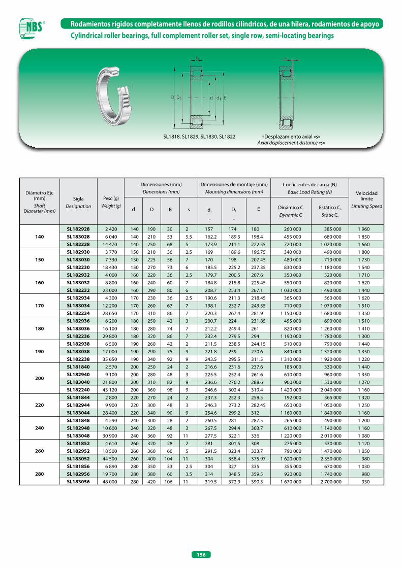
156
Rodamientos rígidos completamente llenos de rodillos cilíndricos, de una hilera, rodamientos de apoyoCylindrical roller bearings, full complement roller set, single row, semi-locating bearings
Diámetro Eje (mm) Shaft
Diameter (mm)
SiglaDesignation
Peso (g)Weight (g)
Dimensiones (mm)Dimensions (mm)
Dimensiones de montaje (mm)Mounting dimensions (mm)
Coeficientes de carga (N)Basic Load Rating (N)
Dinámico CDynamic C
Estático C0
Static C0
D B s
Velocidad limite
Limiting Speedd1
≈
D1
≈
Ed
SL182928SL183028SL182228SL182930SL183030SL182230SL182932SL183032SL182232SL182934SL183034SL182234SL182936SL183036SL182236SL182938SL183038SL182238SL181840SL182940SL183040SL182240SL181844SL182944SL183044SL181848SL182948SL183048SL181852SL182952SL183052SL181856SL182956SL183056
2 420
6 040
14 470
3 770
7 330
18 430
4 000
8 800
23 000
4 300
12 200
28 650
6 200
16 100
29 800
6 500
17 000
35 650
2 570
9 100
21 800
43 120
2 800
9 900
28 400
4 290
10 600
30 900
4 610
18 500
44 500
6 890
19 700
48 000
140 190 30 2
140 210 53 5.5
140 250 68 5
150 210 36 2.5
150 225 56 7
150 270 73 6
160 220 36 2.5
160 240 60 7
160 290 80 6
170 230 36 2.5
170 260 67 7
170 310 86 7
180 250 42 3
180 280 74 7
180 320 86 7
190 260 42 2
190 290 75 9
190 340 92 9
200 250 24 2
200 280 48 3
200 310 82 9
200 360 98 9
220 270 24 2
220 300 48 3
220 340 90 9
240 300 28 2
240 320 48 3
240 360 92 11
260 320 28 2
260 360 60 5
260 400 104 11
280 350 33 2.5
280 380 60 3.5
280 420 106 11
157 174 180
162.2 189.5 198.4
173.9 211.1 222.55
169 189.6 196.75
170 198 207.45
185.5 225.2 237.35
179.7 200.5 207.6
184.8 215.8 225.45
208.7 253.4 267.1
190.6 211.3 218.45
198.1 232.7 243.55
220.3 267.4 281.9
200.7 224 231.85
212.2 249.4 261
232.4 279.5 294
211.5 238.5 244.15
221.8 259 270.6
243.5 295.5 311.5
216.6 231.6 237.6
225.5 252.4 261.6
236.6 276.2 288.6
246.6 302.4 319.4
237.3 252.3 258.5
246.3 273.2 282.45
254.6 299.2 312
260.5 281 287.5
267.5 294.4 303.7
277.5 322.1 336
281 301.5 308
291.5 323.4 333.7
304 358.4 375.97
304 327 335
314 348.5 359.5
319.5 372.9 390.3
260 000 385 000
455 000 680 000
720 000 1 020 000
340 000 490 000
480 000 710 000
830 000 1 180 000
350 000 520 000
550 000 820 000
1 030 000 1 490 000
365 000 560 000
710 000 1 070 000
1 150 000 1 680 000
455 000 690 000
820 000 1 260 000
1 190 000 1 780 000
510 000 790 000
840 000 1 320 000
1 310 000 1 920 000
183 000 330 000
610 000 960 000
960 000 1 530 000
1 420 000 2 040 000
192 000 365 000
650 000 1 050 000
1 160 000 1 840 000
265 000 490 000
610 000 1 140 000
1 220 000 2 010 000
275 000 530 000
790 000 1 470 000
1 620 000 2 550 000
355 000 670 000
920 000 1 740 000
1 670 000 2 700 000
1 960
1 850
1 660
1 800
1 730
1 540
1 710
1 620
1 440
1 620
1 510
1 350
1 510
1 410
1 300
1 440
1 350
1 220
1 440
1 350
1 270
1 160
1 320
1 250
1 160
1 200
1 160
1 080
1 120
1 050
980
1 030
980
930
140
150
160
170
180
190
200
220
240
260
280
SL1818, SL1829, SL1830, SL1822 1) Desplazamiento axial «s»Axial displacement distance «s»
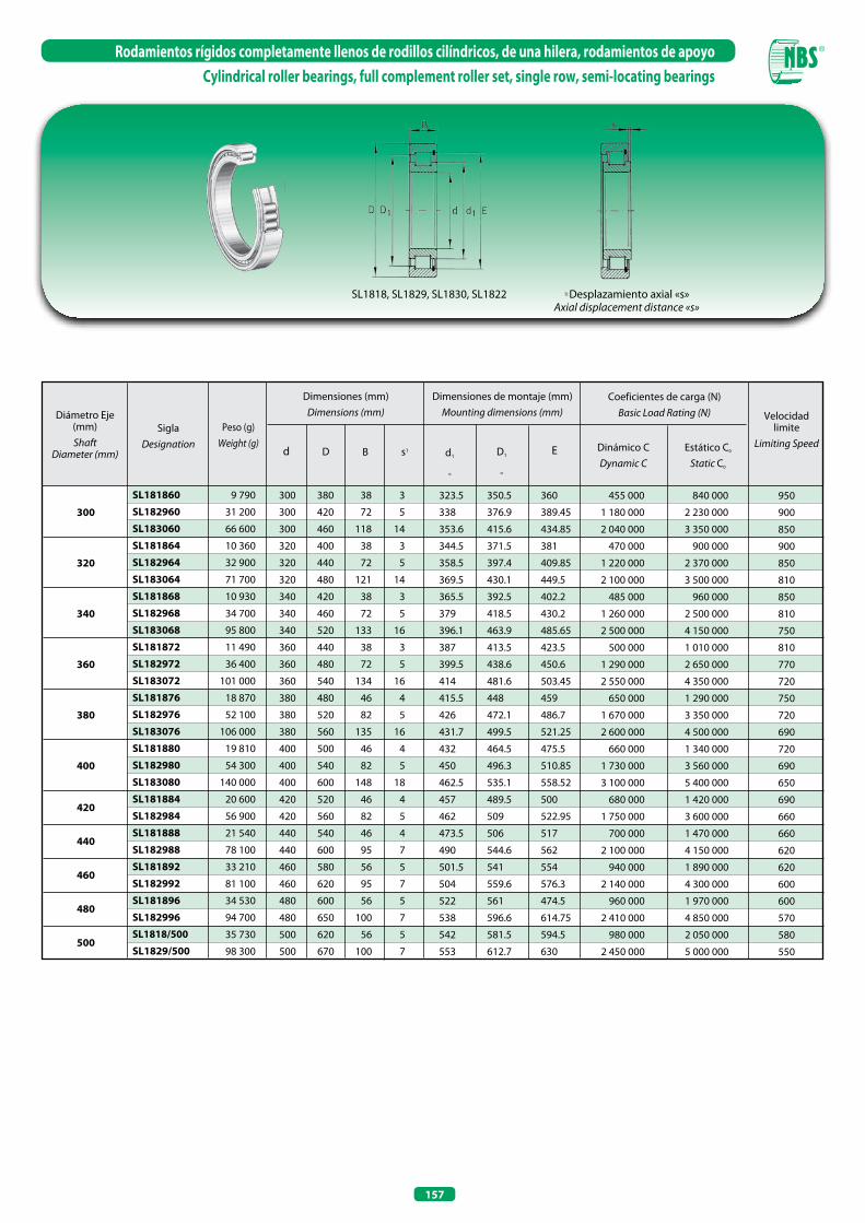
157
Rodamientos rígidos completamente llenos de rodillos cilíndricos, de una hilera, rodamientos de apoyoCylindrical roller bearings, full complement roller set, single row, semi-locating bearings
Diámetro Eje (mm) Shaft
Diameter (mm)
SiglaDesignation
Peso (g)Weight (g)
Dimensiones (mm)Dimensions (mm)
Dimensiones de montaje (mm)Mounting dimensions (mm)
Coeficientes de carga (N)Basic Load Rating (N)
Dinámico CDynamic C
Estático C0
Static C0
D B s1
Velocidad limite
Limiting Speedd1
≈
D1
≈
Ed
SL181860
SL182960
SL183060
SL181864
SL182964
SL183064
SL181868
SL182968
SL183068
SL181872
SL182972
SL183072
SL181876
SL182976
SL183076
SL181880
SL182980
SL183080
SL181884
SL182984
SL181888
SL182988
SL181892
SL182992
SL181896
SL182996SL1818/500
SL1829/500
9 790
31 200
66 600
10 360
32 900
71 700
10 930
34 700
95 800
11 490
36 400
101 000
18 870
52 100
106 000
19 810
54 300
140 000
20 600
56 900
21 540
78 100
33 210
81 100
34 530
94 700
35 730
98 300
300 380 38 3
300 420 72 5
300 460 118 14
320 400 38 3
320 440 72 5
320 480 121 14
340 420 38 3
340 460 72 5
340 520 133 16
360 440 38 3
360 480 72 5
360 540 134 16
380 480 46 4
380 520 82 5
380 560 135 16
400 500 46 4
400 540 82 5
400 600 148 18
420 520 46 4
420 560 82 5
440 540 46 4
440 600 95 7
460 580 56 5
460 620 95 7
480 600 56 5
480 650 100 7
500 620 56 5
500 670 100 7
323.5 350.5 360
338 376.9 389.45
353.6 415.6 434.85
344.5 371.5 381
358.5 397.4 409.85
369.5 430.1 449.5
365.5 392.5 402.2
379 418.5 430.2
396.1 463.9 485.65
387 413.5 423.5
399.5 438.6 450.6
414 481.6 503.45
415.5 448 459
426 472.1 486.7
431.7 499.5 521.25
432 464.5 475.5
450 496.3 510.85
462.5 535.1 558.52
457 489.5 500
462 509 522.95
473.5 506 517
490 544.6 562
501.5 541 554
504 559.6 576.3
522 561 474.5
538 596.6 614.75
542 581.5 594.5
553 612.7 630
455 000 840 000
1 180 000 2 230 000
2 040 000 3 350 000
470 000 900 000
1 220 000 2 370 000
2 100 000 3 500 000
485 000 960 000
1 260 000 2 500 000
2 500 000 4 150 000
500 000 1 010 000
1 290 000 2 650 000
2 550 000 4 350 000
650 000 1 290 000
1 670 000 3 350 000
2 600 000 4 500 000
660 000 1 340 000
1 730 000 3 560 000
3 100 000 5 400 000
680 000 1 420 000
1 750 000 3 600 000
700 000 1 470 000
2 100 000 4 150 000
940 000 1 890 000
2 140 000 4 300 000
960 000 1 970 000
2 410 000 4 850 000
980 000 2 050 000
2 450 000 5 000 000
950
900
850
900
850
810
850
810
750
810
770
720
750
720
690
720
690
650
690
660
660
620
620
600
600
570
580
550
300
320
340
360
380
400
420
440
460
480
500
SL1818, SL1829, SL1830, SL1822 1) Desplazamiento axial «s»Axial displacement distance «s»

158
Rodamientos rígidos completamente llenos de rodillos cilíndricos de dos hileras , rodamientos de apoyo, rodamientos fijos, rodamientos libresCylindrical roller bearings, full complement roller set, double row, semi-locating bearings, locating bearings, non-locating bearings
SL1850 SL0148, SL0149 SL0248, SL0249
Diámetro Eje (mm)
ShaftDiameter
(mm)
SiglaDesignation
Rodamientos de apoyo
Semi-locating bearings
Rodamientos fijos
Locatingbearings
Rodamientos libres
Non-locating bearings
Peso (g)Weight (g)
Dimensiones (mm)Dimensions (mm)
Dimensiones de montaje (mm)Mounting dimensions (mm)
Coeficientes de carga (N)Basic Load Rating (N)
Dinámico CDynamic C
Estático C0
Static C0
D B s
Velocidad limite
Limiting Speedd1
≈
C D1
≈
Ed
SL185004SL185005SL185006SL185007SL185008SL185009SL185010SL185011
––
SL185012SL185013
––
SL185014SL185015
––
SL185016SL185017
––
SL185018––
SL185020––
SL185022––
SL185024
––––––––
SL014912–––
SL014914–––
SL014916–––
SL014918––
SL014920––
SL014922––
SL014924––
–––––––––
SL024912–––
SL024914–––
SL024916–––
SL024918––
SL024920––
SL024922––
SL024924–
2025303540455055
60
65
70
75
80
85
90
100
110
120
200
230
350
460
560
710
760
1 160
490
470
1 240
1 320
780
750
1 850
1 930
880
850
2 590
2 720
1 350
1 300
3 620
1 950
1 900
3 940
2 150
2 100
6 320
2 950
2 850
6 700
20 42 30 1
25 47 30 1
30 55 34 1.5
35 62 36 1.5
40 68 38 1.5
45 75 40 1.5
50 80 40 1.5
55 90 46 1.5
60 85 25 –
60 85 25 1
60 95 46 1.5
65 100 46 1.5
70 100 30 –
70 100 30 1
70 110 54 3
75 115 54 3
80 110 30 –
80 110 30 1
80 125 60 3.5
85 130 60 3.5
90 125 35 –
90 125 35 1.5
90 140 67 4
100 140 40 –
100 140 40 2
100 150 67 4
110 150 40 –
110 150 40 2
110 170 80 5
120 165 45 –
120 165 45 3
120 180 80 5
15 28.4 33.3 36.81
15 34.5 39 42.51
17 40 45.3 49.6
18 44.9 51.2 55.52
19 50.5 57.2 61.74
20 55.3 62.6 66.85
20 59.1 67.6 72.33
23 68.5 78.7 83.54
12.5 70.3 73.5 –
12.5 70.3 – 77.51
23 71.7 81.9 86.74
23 78.1 88.3 93.09
15 82.5 87.4 –
15 82.5 – 91.87
27 81.5 95.7 100.28
27 89 102.9 107.9
15 91.4 96.2 –
15 91.4 – 100.78
30 95 111.7 117.4
30 99 116.1 121.95
17.5 103.9 110.7 –
17.5 103 – 115.2
33.5 106.1 124.5 130.65
20 116.4 125 –
20 116.4 – 129.6
33.5 115.7 134 140.2
20 125 133.6 –
20 125 – 138.2
40 127.3 149.3 156.7
22.5 138.6 148.6 –
22.5 138.6 – 153.55
40 138.8 160.7 168.15
53 000 53 000
60 000 65 000
78 000 84 000
94 000 109 000
113 000 136 000
120 000 151 000
151 000 191 000
206 000 275 000
71 000 125 000
71 000 125 000
212 000 290 000
223 000 320 000
108 000 189 000
108 000 189 000
265 000 355 000
275 000 390 000
115 000 211 000
115 000 211 000
295 000 450 000
305 000 475 000
155 000 295 000
155 000 295 000
355 000 560 000
196 000 380 000
196 000 380 000
375 000 620 000
204 000 410 000
204 000 410 000
490 000 790 000
228 000 455 000
228 000 455 000
520 000 870 000
10 500
9 000
7 600
6 700
6 000
5 400
5 000
4 450
4 450
4 450
4 200
3 550
3 800
3 800
3 600
3 400
3 400
3 400
3 150
3 000
3 000
3 000
2 800
2 700
2 700
2 600
2 490
2 490
2 310
2 270
2 270
2 160
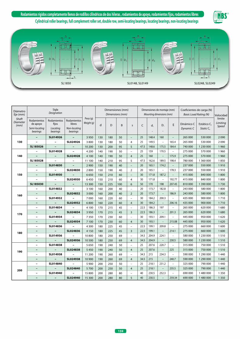
159
Rodamientos rígidos completamente llenos de rodillos cilíndricos de dos hileras , rodamientos de apoyo, rodamientos fijos, rodamientos libresCylindrical roller bearings, full complement roller set, double row, semi-locating bearings, locating bearings, non-locating bearings
Diámetro Eje (mm)
ShaftDiameter
(mm)
SiglaDesignation
Rodamientos de apoyo
Semi-locating bearings
Rodamientos fijos
Locatingbearings
Rodamientos libres
Non-locating bearings
Peso (g)Weight (g)
Dimensiones (mm)Dimensions (mm)
Dimensiones de montaje (mm)Mounting dimensions (mm)
Coeficientes de carga (N)Basic Load Rating (N)
Dinámico CDynamic C
Estático C0
Static C0
D B s
Velocidad limite
Limiting Speedd1
≈
C D1
≈
Ed
–
–
SL185026
–
–
SL185028
–
–
–
–
SL185030
–
–
–
–
–
–
–
–
–
–
–
–
–
–
–
–
–
–
–
–
SL014926
–
–
SL014928
–
–
SL014830
–
SL014930
–
–
SL014832
–
SL014932
–
SL014834
–
SL014934
–
SL014836
–
SL014936
–
SL014838
–
SL014938
–
SL014840
–
SL014940
–
–
SL024926
–
–
SL024928
–
–
SL024830
–
SL024930
–
–
SL024832
–
SL024932
–
SL024834
–
SL024934
–
SL024836
–
SL024936
–
SL024838
–
SL024938
–
SL024840
–
SL024940
3 950
3 800
10 200
4 200
4 100
11 100
2 900
2 800
6 650
6 450
13 300
3 100
3 000
7 000
6 800
4 100
3 950
7 350
7 100
4 300
4 150
10 800
10 500
5 650
5 450
11 200
10 900
5 900
5 700
15 800
15 300
130 180 50 –
130 180 50 4
130 200 95 5
140 190 50 –
140 190 50 4
140 210 95 5
150 190 40 –
150 190 40 2
150 210 60 –
150 210 60 4
150 225 100 6
160 200 40 –
160 200 40 2
160 220 60 –
160 220 60 4
170 215 45 –
170 215 45 3
170 230 60 –
170 230 60 4
180 225 45 –
180 225 45 3
180 250 69 –
180 250 69 4
190 240 50 –
190 240 50 4
190 260 69 –
190 260 69 4
200 250 50 –
200 250 50 4
200 280 80 –
200 280 80 5
25 148.4 160 –
25 149.5 – 165.4
47.5 148.6 175.5 184.4
25 159 170.5 –
25 160 – 175.9
47.5 162.6 189.5 198.4
20 165.1 174.2 –
20 165.1 – 178.3
30 171.8 187.2 –
30 171.8 – 192.77
50 170 198 207.45
20 173.7 182.8 –
20 173.7 – 186.9
30 184.2 200.3 –
30 184.2 – 206.16
22.5 186.3 197 –
22.5 186.3 – 201.3
30 193.1 209.1 –
30 193.1 – 215.08
22.5 199.1 209.8 –
22.5 199.1 – 214.1
34.5 204.9 224.1 –
34.5 204.9 – 230.5
25 207.6 220.7 –
25 207.6 – 225
34.5 215 234.3 –
34.5 215 – 240.7
25 218.1 231.2 –
25 218.1 – 235.5
40 230.5 252.3 –
40 230.5 – 259.34
265 000 530 000
265 000 530 000
740 000 1 230 000
275 000 570 000
275 000 570 000
780 000 1 360 000
237 000 550 000
237 000 550 000
415 000 840 000
415 000 840 000
810 000 1 390 000
243 000 580 000
243 000 580 000
435 000 900 000
435 000 900 000
265 000 620 000
265 000 620 000
445 000 950 000
445 000 950 000
275 000 660 000
275 000 660 000
580 000 1 230 000
580 000 1 230 000
315 000 750 000
315 000 750 000
590 000 1 290 000
590 000 1 290 000
325 000 790 000
325 000 790 000
690 000 1 480 000
690 000 1 480 000
2 090
2 090
1 960
1 960
1 960
1 850
1 910
1 910
1 800
1 800
1 730
1 800
1 800
1 710
1 710
1 680
1 680
1 620
1 620
1 600
1 600
1 510
1 510
1 510
1 510
1 440
1 440
1 440
1 440
1 350
1 350
130
140
150
160
170
180
190
200
SL1850 SL0148, SL0149 SL0248, SL0249

160
Rodamientos rígidos completamente llenos de rodillos cilíndricos de dos hileras , rodamientos de apoyo, rodamientos fijos, rodamientos libresCylindrical roller bearings, full complement roller set, double row, semi-locating bearings, locating bearings, non-locating bearings
SL0148, SL0149 SL0248, SL0249
Diámetro Eje (mm)
ShaftDiameter
(mm)
SiglaDesignation
Rodamientos fijosLocatingbearings
Rodamientos libresNon-locating
bearings
Dimensiones (mm)Dimensions (mm)
Dimensiones de montaje (mm)Mounting dimensions (mm)
Coeficientes de carga (N)Basic Load Rating (N)
Dinámico CDynamic C
Estático C0
Static C0
Velocidad limite
Limiting Speedd1
≈
D1
≈
E
SL014844–
SL014944–
SL014848 –
SL014948–
SL014852–
SL014952–
SL014856–
SL014956–
SL014860–
SL014960–
SL014864–
SL014964–
SL014868–
SL014968–
–SL024844
–SL024944
–SL024848
–SL024948
–SL024852
–SL024952
–SL024856
–SL024956
–SL024860
–SL024960
–SL024864
–SL024964
–SL024868
–SL024968
Peso (g)Weight (g)
6 400
6 200
17 200
16 700
10 000
9 900
18 500
17 900
11 000
10 600
32 000
31 200
16 000
15 600
34 000
33 100
23 000
22 000
53 000
51 900
24 000
23 500
56 000
54 900
25 500
25 000
59 000
57 800
D B s Cd
220 270 50 – 25
220 270 50 4 25
220 300 80 – 40
220 300 80 5 40
240 300 60 – 30
240 300 60 4 30
240 320 80 – 40
240 320 80 5 40
260 320 60 – 30
260 320 60 4 30
260 360 100 – 50
260 360 100 6 50
280 350 69 – 34.5
280 350 69 4 34.5
280 380 100 – 50
280 380 100 6 50
300 380 80 – 40
300 380 80 6 40
300 420 118 – 59
300 420 118 6 59
320 400 80 – 40
320 400 80 6 40
320 440 118 – 59
320 440 118 6 59
340 420 80 – 40
340 420 80 6 40
340 460 118 – 59
340 460 118 6 59
239.1 252.3 –
239.1 – 256.5
248 268.5 –
248 – 276.52
259.5 276.7 –
259.5 – 281.9
270.6 292.3 –
270.6 – 299.46
281.8 298.8 –
281.8 – 304.2
294.5 322.1 –
294.5 – 331.33
306.8 326.4 –
306.8 – 332.4
316.5 344.6 –
316.5 – 353.34
327.9 349.9 –
327.9 – 356.7
340.7 374.3 –
340.7 – 385.51
350.9 372.9 –
350.9 – 379.7
367.5 401.1 –
367.5 – 412.27
368.1 390.1 –
368.1 – 396.9
385.3 418.9 –
385.3 – 430.11
340 000 870 000
340 000 870 000
720 000 1 590 000
720 000 1 590 000
520 000 1 290 000
520 000 1 290 000
750 000 1 740 000
750 000 1 740 000
540 000 1 400 000
540 000 1 400 000
1 120 000 2 500 000
1 120 000 2 500 000
710 000 1 860 000
710 000 1 860 000
1 170 000 2 700 000
1 170 000 2 700 000
830 000 2 120 000
830 000 2 120 000
1 650 000 3 800 000
1 650 000 3 800 000
860 000 2 280 000
860 000 2 280 000
1 720 000 4 100 000
1 720 000 4 100 000
880 000 2 390 000
880 000 2 390 000
1 770 000 4 300 000
1 770 000 4 300 000
1 320
1 320
1 250
1 250
1 200
1 200
1 160
1 160
1 120
1 120
1 050
1 050
1 030
1 030
980
980
950
950
900
900
900
900
850
850
850
850
810
810
220
240
260
280
300
320
340
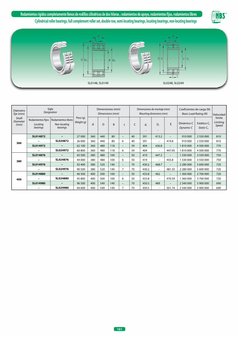
161
Rodamientos rígidos completamente llenos de rodillos cilíndricos de dos hileras , rodamientos de apoyo, rodamientos fijos, rodamientos libresCylindrical roller bearings, full complement roller set, double row, semi-locating bearings, locating bearings, non-locating bearings
SL0148, SL0149 SL0248, SL0249
Diámetro Eje (mm)
ShaftDiameter
(mm)
SiglaDesignation
Rodamientos fijosLocatingbearings
Rodamientos libresNon-locating
bearings
Dimensiones (mm)Dimensions (mm)
Dimensiones de montaje (mm)Mounting dimensions (mm)
Coeficientes de carga (N)Basic Load Rating (N)
Dinámico CDynamic C
Estático C0
Static C0
Velocidad limite
Limiting Speedd1
≈
D1
≈
E
SL014872
–
SL014972
–
SL014876
–
SL014976
–
SL014880
–
SL014980
–
–
SL024872
–
SL024972
–
SL024876
–
SL024976
–
SL024880
–
SL024980
Peso (g)Weight (g)
27 000
26 000
62 100
60 800
45 500
44 000
92 400
90 500
46 500
45 800
96 500
94 600
D B s Cd
360 440 80 – 40
360 440 80 6 40
360 480 118 – 59
360 480 118 6 59
380 480 100 – 50
380 480 100 6 50
380 520 140 – 70
380 520 140 7 70
400 500 100 – 50
400 500 100 6 50
400 540 140 – 70
400 540 140 7 70
391 413.2 –
391 – 419.8
404 436.8 –
404 – 447.95
419 447.2 –
419 – 455.8
430.2 468.7 –
430.2 – 481.35
433.8 462 –
433.8 – 470.59
450.5 489 –
450.5 – 501.74
910 000 2 550 000
910 000 2 550 000
1 810 000 4 500 000
1 810 000 4 500 000
1 330 000 3 550 000
1 330 000 3 550 000
2 280 000 5 600 000
2 280 000 5 600 000
1 360 000 3 700 000
1 360 000 3 700 000
2 340 000 5 900 000
2 340 000 5 900 000
810
810
770
770
750
750
720
720
720
720
690
690
360
380
400

162
Rodamientos completamente llenos de rodillos cilíndricos con ranuras para anillos elásticos, blindados, rodamientos fijosCylindrical roller bearings with snap ring grooves full complement roller set, locating bearings
SL0450..-PPSL04..-PP
20253035404550556065707580859095
100110120
130
140
150
160
Diámetro Eje (mm) Shaft
Diameter (mm)
SiglaDesignation
Peso (g)Weight (g)
Dimensiones (mm)Dimensions (mm)
xtmD1
≈
C1CBDd
SL045004-PPSL045005-PPSL045006-PPSL045007-PPSL045008-PPSL045009-PPSL045010-PPSL045011-PPSL045012-PPSL045013-PPSL045014-PPSL045015-PPSL045016-PPSL045017-PPSL045018-PPSL045019-PPSL045020-PPSL045022-PPSL045024-PPSL045026-PPSL04130-PPSL045028-PPSL04140-PPSL045030-PPSL04150-PPSL045032-PPSL04160-PP
200
240
370
480
560
700
760
1 180
1 260
1 330
1 870
1 960
2 710
2 830
3 710
3 880
3 950
6 570
7 040
10 500
7 500
11 100
8 000
13 300
8 400
16 600
8 800
20
25
30
35
40
45
50
55
60
65
70
75
80
85
90
95
100
110
120
130
130
140
140
150
150
160
160
42
47
55
62
68
75
80
90
95
100
110
115
125
130
140
145
150
170
180
200
190
210
200
225
210
240
220
30
30
34
36
38
40
40
46
46
46
54
54
60
60
67
67
67
80
80
95
80
95
80
100
80
109
80
29
29
33
35
37
39
39
45
45
45
53
53
59
59
66
66
66
79
79
94
79
94
79
99
79
108
79
24.7
24.7
28.2
30.2
32.2
34.2
34.2
40.2
40.2
40.2
48.2
48.2
54.2
54.2
59.2
59.2
59.2
70.2
71.2
83.2
71.2
83.2
71.2
87.2
71.2
95.2
71.2
40.2
45.2
53
60
65.8
72.8
77.8
87.4
92.4
97.4
107.1
112.1
122.1
127.1
137
142
147
167
176
196
186
206
196
221
206
236
216
1.8
1.8
2.1
2.1
2.7
2.7
2.7
3.2
3.2
3.2
4.2
4.2
4.2
4.2
4.2
4.2
4.2
4.2
4.2
4.2
4.2
5.2
4.2
5.2
5.2
5.2
5.2
0.5
0.5
0.5
0.5
0.8
0.8
0.8
1
1
1
1
1
1.5
1.5
1.5
1.5
1.5
1.8
1.8
1.8
1.8
1.8
1.8
2
1.8
2
1.8
22.5
22.5
25.5
27.5
28.5
30.5
30.5
36
36
36
42
42
48
48
54
54
54
64
64
77
64
77
64
80
64
89
64

163
Rodamientos completamente llenos de rodillos cilíndricos con ranuras para anillos elásticos, blindados, rodamientos fijosCylindrical roller bearings with snap ring grooves full complement roller set, locating bearings
1) Para anillos elásticos AES For AES elastic rings
2) Para anillos de anclaje For retaining rings
Dimensiones de montaje (mm)Mounting dimensions (mm)
Coeficientes de carga (N)Basic Load Rating (N)
Velocidad limiteLimiting Speed
grasagrease
Anillo elásticoAES
Elastic ringsAES
Anillo de retención
Retaining rings
d2 d3d1
21.5
21.5
25
27
28
30
30
35
35
35
43
43
49
49
54
54
54
65
65
77
65
77
65
81
65
89
65
21
21
24
26
27
29
29
34
34
34
40
40
46
46
51
51
51
62
63
75
63
73
63
77
61
85
61
30.55
35.35
40.6
46.1
51.4
57
61.8
68.6
73.7
78.8
84.5
89.95
97.1
103.9
109.3
113.35
117.35
131.55
140.9
156.75
150.55
165.4
159.95
175.7
174.4
189
184.05
34
39
44
50
55
61
66
73
79
84
91
97
105
112
118
122
128
143
153
170
160
181
170
192
185
207
196
47
52
60
67
75
82
87
99
104
109
119
124
137
142
152
157
162
182
196
216
206
226
216
245
226
260
236
40 500
44 500
50 000
63 000
76 000
92 000
97 000
115 000
120 000
125 000
168 000
194 000
203 000
211 000
305 000
315 000
330 000
395 000
410 000
540 000
430 000
610 000
445 000
710 000
465 000
740 000
480 000
49 000
58 000
67 000
88 000
103 000
130 000
142 000
175 000
189 000
203 000
265 000
300 000
325 000
350 000
510 000
530 000
550 000
680 000
740 000
960 000
790 000
1 100 000
840 000
1 260 000
920 000
1 360 000
970 000
4 000
3 600
3 000
2 600
2 400
2 200
2 000
1 800
1 700
1 600
1 400
1 400
1 300
1 200
1 100
1 100
1 000
900
900
800
800
750
750
700
700
650
700
AES42
AES47
AES55
AES62
AES68
AES75
AES80
AES90
AES95
AES100
AES110
AES115
AES125
AES130
AES140
AES145
AES150
AES170
AES180
AES200
AES190
AES210
AES200
AES225
AES210
AES240
AES220
42X1,75
47X1,75
55X2
62X2
68X2,5
75X2,5
80X2,5
90X3
95X3
100X3
110X4
115X4
125X4
130X4
140X4
145X4
150X4
170X4
180X4
200X4
190X4
210X5
200X4
225X5
210X5
240X5
220X5
Ca1
-0,2
1)Ca2
-0,2
2) 1) Dinámico CDynamic C
Estático C0
Static C0
SL0450..-PPSL04..-PP
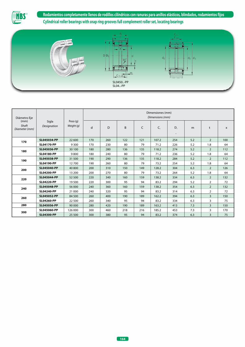
164
Rodamientos completamente llenos de rodillos cilíndricos con ranuras para anillos elásticos, blindados, rodamientos fijosCylindrical roller bearings with snap ring grooves full complement roller set, locating bearings
Diámetro Eje (mm) Shaft
Diameter (mm)
SiglaDesignation
Peso (g)Weight (g)
Dimensiones (mm)Dimensions (mm)
xtmD1
≈
C1CBDd
SL045034-PPSL04170-PPSL045036-PPSL04180-PPSL045038-PPSL04190-PPSL045040-PPSL04200-PPSL045044-PPSL04220-PPSL045048-PPSL04240-PPSL045052-PPSL04260-PPSL045056-PPSL045060-PPSL04300-PP
22 600
9 300
30 100
9 800
31 500
12 700
40 800
13 200
52 500
19 500
56 000
21 000
84 500
22 500
90 000
126 000
25 500
170
170
180
180
190
190
200
200
220
220
240
240
260
260
280
300
300
260
230
280
240
290
260
310
270
340
300
360
320
400
340
420
460
380
122
80
136
80
136
80
150
80
160
95
160
95
190
95
190
218
95
121
79
135
79
135
79
149
79
159
94
159
94
189
94
189
216
94
107.2
71.2
118.2
71.2
118.2
73.2
128.2
73.2
138.2
83.2
138.2
83.2
162.2
83.2
163.2
185.2
83.2
254
226
274
236
284
254
304
264
334
294
354
314
394
334
413
453
374
5.2
5.2
5.2
5.2
5.2
5.2
6.3
5.2
6.3
5.2
6.3
6.3
6.3
6.3
7.3
7.3
6.3
2
1.8
2
1.8
2
1.8
2
1.8
2
2
2
2
3
3
3
3
3
100
64
112
64
112
64
126
64
132
72
132
72
150
75
150
170
75
170
180
190
200
220
240
260
280
300
SL0450..-PPSL04..-PP

165
Rodamientos completamente llenos de rodillos cilíndricos con ranuras para anillos elásticos, blindados, rodamientos fijosCylindrical roller bearings with snap ring grooves full complement roller set, locating bearings
1) Para anillos elásticos AES - For AES elastic rings
2) Para anillos de anclaje - For retaining rings
Dimensiones de montaje (mm)Mounting dimensions (mm)
Coeficientes de carga (N)Basic Load Rating (N)
Velocidad limiteLimiting Speed
grasagrease
Anillo elásticoAES
Elastic ringsAES
Anillo de retención
Retaining rings
d2 d3d1
99
65
110
65
110
65
120
65
130
75
130
75
154
75
154
176
75
97
61
108
61
108
63
116
63
126
73
126
71
150
71
149
171
71
200.7
193.9
217.8
203.1
225.65
217.55
243.05
227.15
259.85
248.7
279.25
271.7
304.95
292.7
320.95
346.85
328
220
206
239
216
248
231
267
241
286
264
305
287
336
310
354
375
346
282
250
302
260
312
282
336
292
366
322
386
346
426
366
453
493
406
960 000
490 000
1 140 000
500 000
1 160 000
520 000
1 350 000
540 000
1 570 000
700 000
1 630 000
740 000
2 380 000
840 000
2 600 000
3 000 000
900 000
1 750 000
1 030 000
2 130 000
1 080 000
2 210 000
1 130 000
2 600 000
1 210 000
3 050 000
1 550 000
3 300 000
1 700 000
4 700 000
1 990 000
5 200 000
5 800 000
2 250 000
600
650
550
600
550
550
500
550
480
480
440
480
400
440
380
340
380
AES260
AES230
AES280
AES240
AES290
AES260
AES310
AES270
AES340
AES300
AES360
AES320
AES400
AES340
AES420
AES460
AES380
260X5
230X5
280X5
240X5
290X5
260X5
310X6
270X5
340X6
300X5
360X6
320X6
400X6
340X6
420X7
460X7
380X6
Ca1
-0,2
1)Ca2
-0,2
2) 1) Dinámico CDynamic C
Estático C0
Static C0
SL0450..-PPSL04..-PP
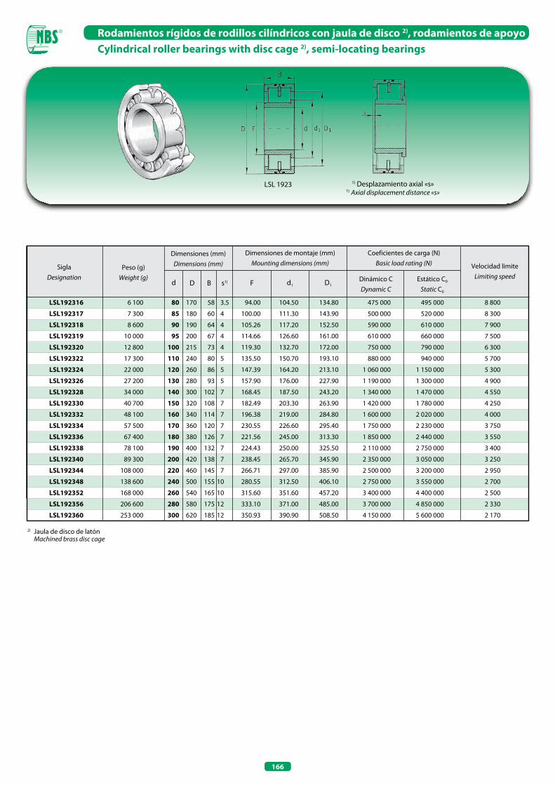
166
Rodamientos rígidos de rodillos cilíndricos con jaula de disco 2), rodamientos de apoyoCylindrical roller bearings with disc cage 2), semi-locating bearings
LSL 1923 1) Desplazamiento axial «s»1) Axial displacement distance «s»
LSL192316
LSL192317
LSL192318
LSL192319
LSL192320
LSL192322
LSL192324
LSL192326
LSL192328
LSL192330
LSL192332
LSL192334
LSL192336
LSL192338
LSL192340
LSL192344
LSL192348
LSL192352
LSL192356
LSL192360
6 100
7 300
8 600
10 000
12 800
17 300
22 000
27 200
34 000
40 700
48 100
57 500
67 400
78 100
89 300
108 000
138 600
168 000
206 600
253 000
80 170 58 3.5
85 180 60 4
90 190 64 4
95 200 67 4
100 215 73 4
110 240 80 5
120 260 86 5
130 280 93 5
140 300 102 7
150 320 108 7
160 340 114 7
170 360 120 7
180 380 126 7
190 400 132 7
200 420 138 7
220 460 145 7
240 500 155 10
260 540 165 10
280 580 175 12
300 620 185 12
94.00 104.50 134.80
100.00 111.30 143.90
105.26 117.20 152.50
114.66 126.60 161.00
119.30 132.70 172.00
135.50 150.70 193.10
147.39 164.20 213.10
157.90 176.00 227.90
168.45 187.50 243.20
182.49 203.30 263.90
196.38 219.00 284.80
230.55 226.60 295.40
221.56 245.00 313.30
224.43 250.00 325.50
238.45 265.70 345.90
266.71 297.00 385.90
280.55 312.50 406.10
315.60 351.60 457.20
333.10 371.00 485.00
350.93 390.90 508.50
SiglaDesignation
Peso (g)Weight (g)
Dimensiones (mm)Dimensions (mm)
Dimensiones de montaje (mm)Mounting dimensions (mm)
d D s1)B F d1 D1
Coeficientes de carga (N)Basic load rating (N) Velocidad limite
Limiting speedDinámico CDynamic C
Estático C0
Static C0
475 000 495 000
500 000 520 000
590 000 610 000
610 000 660 000
750 000 790 000
880 000 940 000
1 060 000 1 150 000
1 190 000 1 300 000
1 340 000 1 470 000
1 420 000 1 780 000
1 600 000 2 020 000
1 750 000 2 230 000
1 850 000 2 440 000
2 110 000 2 750 000
2 350 000 3 050 000
2 500 000 3 200 000
2 750 000 3 550 000
3 400 000 4 400 000
3 700 000 4 850 000
4 150 000 5 600 000
8 800
8 300
7 900
7 500
6 300
5 700
5 300
4 900
4 550
4 250
4 000
3 750
3 550
3 400
3 250
2 950
2 700
2 500
2 330
2 170
2) Jaula de disco de latón Machined brass disc cage
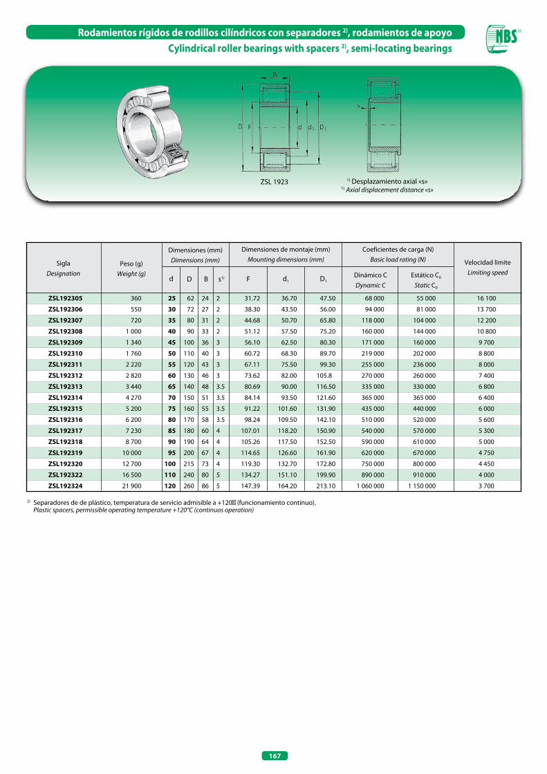
167
Rodamientos rígidos de rodillos cilíndricos con separadores 2), rodamientos de apoyoCylindrical roller bearings with spacers 2), semi-locating bearings
ZSL 1923 1) Desplazamiento axial «s»1) Axial displacement distance «s»
ZSL192305
ZSL192306
ZSL192307
ZSL192308
ZSL192309
ZSL192310
ZSL192311
ZSL192312
ZSL192313
ZSL192314
ZSL192315
ZSL192316
ZSL192317
ZSL192318
ZSL192319
ZSL192320
ZSL192322
ZSL192324
360
550
720
1 000
1 340
1 760
2 220
2 820
3 440
4 270
5 200
6 200
7 230
8 700
10 000
12 700
16 500
21 900
25 62 24 2
30 72 27 2
35 80 31 2
40 90 33 2
45 100 36 3
50 110 40 3
55 120 43 3
60 130 46 3
65 140 48 3.5
70 150 51 3.5
75 160 55 3.5
80 170 58 3.5
85 180 60 4
90 190 64 4
95 200 67 4
100 215 73 4
110 240 80 5
120 260 86 5
31.72 36.70 47.50
38.30 43.50 56.00
44.68 50.70 65.80
51.12 57.50 75.20
56.10 62.50 80.30
60.72 68.30 89.70
67.11 75.50 99.30
73.62 82.00 105.8
80.69 90.00 116.50
84.14 93.50 121.60
91.22 101.60 131.90
98.24 109.50 142.10
107.01 118.20 150.90
105.26 117.50 152.50
114.65 126.60 161.90
119.30 132.70 172.80
134.27 151.10 199.90
147.39 164.20 213.10
SiglaDesignation
Peso (g)Weight (g)
Dimensiones (mm)Dimensions (mm)
Dimensiones de montaje (mm)Mounting dimensions (mm)
d D s1)B F d1 D1
Coeficientes de carga (N)Basic load rating (N) Velocidad limite
Limiting speedDinámico CDynamic C
Estático C0
Static C0
68 000 55 000
94 000 81 000
118 000 104 000
160 000 144 000
171 000 160 000
219 000 202 000
255 000 236 000
270 000 260 000
335 000 330 000
365 000 365 000
435 000 440 000
510 000 520 000
540 000 570 000
590 000 610 000
620 000 670 000
750 000 800 000
890 000 910 000
1 060 000 1 150 000
16 100
13 700
12 200
10 800
9 700
8 800
8 000
7 400
6 800
6 400
6 000
5 600
5 300
5 000
4 750
4 450
4 000
3 700
2) Separadores de de plástico, temperatura de servicio admisible a +120℃ (funcionamiento continuo). Plastic spacers, permissible operating temperature +120°C (continuos operation)

PATINES CON RECIRCULACIÓN DE RODILLOSRECIRCULATING LINEAR ROLLER BEARINGS

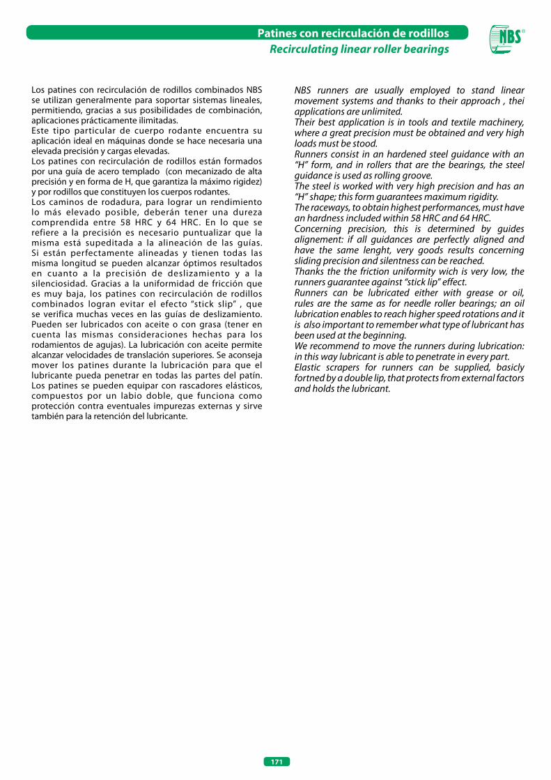
171
Patines con recirculación de rodillosRecirculating linear roller bearings
Los patines con recirculación de rodillos combinados NBS se utilizan generalmente para soportar sistemas lineales, permitiendo, gracias a sus posibilidades de combinación, aplicaciones prácticamente ilimitadas. Este tipo particular de cuerpo rodante encuentra su aplicación ideal en máquinas donde se hace necesaria una elevada precisión y cargas elevadas.Los patines con recirculación de rodillos están formados por una guía de acero templado (con mecanizado de alta precisión y en forma de H, que garantiza la máximo rigidez) y por rodillos que constituyen los cuerpos rodantes.Los caminos de rodadura, para lograr un rendimiento lo más elevado posible, deberán tener una dureza comprendida entre 58 HRC y 64 HRC. En lo que se refiere a la precisión es necesario puntualizar que la misma está supeditada a la alineación de las guías. Si están perfectamente alineadas y tienen todas las misma longitud se pueden alcanzar óptimos resultados en cuanto a la precisión de deslizamiento y a la silenciosidad. Gracias a la uniformidad de fricción que es muy baja, los patines con recirculación de rodillos combinados logran evitar el efecto “stick slip” , que se verifica muchas veces en las guías de deslizamiento. Pueden ser lubricados con aceite o con grasa (tener en cuenta las mismas consideraciones hechas para los rodamientos de agujas). La lubricación con aceite permite alcanzar velocidades de translación superiores. Se aconseja mover los patines durante la lubricación para que el lubricante pueda penetrar en todas las partes del patín. Los patines se pueden equipar con rascadores elásticos, compuestos por un labio doble, que funciona como protección contra eventuales impurezas externas y sirve también para la retención del lubricante.
NBS runners are usually employed to stand linear movement systems and thanks to their approach , thei applications are unlimited.Their best application is in tools and textile machinery, where a great precision must be obtained and very high loads must be stood.Runners consist in an hardened steel guidance with an “H” form, and in rollers that are the bearings, the steel guidance is used as rolling groove.The steel is worked with very high precision and has an “H” shape; this form guarantees maximum rigidity.The raceways, to obtain highest performances, must have an hardness included within 58 HRC and 64 HRC.Concerning precision, this is determined by guides alignement: if all guidances are perfectly aligned and have the same lenght, very goods results concerning sliding precision and silentness can be reached.Thanks the the friction uniformity wich is very low, the runners guarantee against “stick lip” effect.Runners can be lubricated either with grease or oil, rules are the same as for needle roller bearings; an oil lubrication enables to reach higher speed rotations and it is also important to remember what type of lubricant has been used at the beginning.We recommend to move the runners during lubrication: in this way lubricant is able to penetrate in every part.Elastic scrapers for runners can be supplied, basicly fortned by a double lip, that protects from external factors and holds the lubricant.
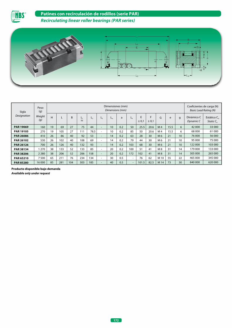
172
Patines con recirculación de rodillos (serie PAR)Recirculating linear roller bearings (PAR series)
Producto disponible bajo demandaAvailable only under request
SiglaDesignation
Dimensiones (mm)Dimensions (mm)
Peso(g)
Weight(g)
160 19 69 27 75 44 - 10 0.2 50 25.5 20.6 M 4 15.5 6
270 19 105 27 111 78.5 - 10 0.2 85 50 20.6 M 4 15.5 6
410 26 86 40 92 53 - 14 0.2 63 28 30 M 6 21 10
530 26 102 40 108 69 - 14 0.2 79 44 30 M 6 21 10
700 26 126 40 132 93 - 14 0.2 103 68 30 M 6 21 10
1 270 38 133 52 133 85 - 20 0.2 100 51 41 M 8 31 14
2 280 38 206 52 206 158 - 20 0.2 172 102 41 M 8 31 14
7 500 65 211 76 234 134 - 30 0.5 - 76 62 M 10 55 22
16 000 85 281 104 303 185 - 40 0.5 - 101.5 82.5 M 14 73 30
42 000 33 000
68 000 61 000
76 000 56 000
95 000 75 000
122 000 103 000
179 000 133 000
305 000 265 000
465 000 345 000
840 000 620 000
H L B L1
≈L2
Coeficientes de carga (N)Basic Load Rating (N)
Dinámico CDynamic C
Estático Co
Static Co
PAR 19069PAR 19105PAR 26086PAR 26102PAR 26126PAR 38134PAR 38206PAR 65210PAR 85280
L3 Lw L4 E± 0,1
F± 0,1
G e ga

AGUJASNEEDLE ROLLERS


175
AgujasNeedle rollers
Las agujas NBS permiten la realización de rodamientos completamente llenos que, con un volumen constructivo mínimo, pueden soportar elevadas cargas.Estando las agujas directamente entre el eje y el alojamiento, sin ningún aro interior ni exterior, el eje puede alcanzar el mayor diámetro posible, logrando así los mejores resultados en lo que se refiere a la rigidez y a la capacidad de carga. En el caso de aplicaciones que requieran agujas particularmente largas respecto al diámetro del eje, es conveniente utilizar dos hileras de agujas de igual longitud, divididas con separadores.Para lograr la máxima capacidad de carga es necesario que los caminos de rodadura tengan una superficie con una dureza comprendida entre los 58 HRC y los 64 HRC.Las agujas se fabrican con acero templado para rodamientos y tienen también una dureza comprendida dentro del intervalo indicado para las pistas. Bajo demanda pueden suministrarse de acero inoxidable templado. La rugosidad superficial de las agujas es inferior a 0,2 µm.
Diferencia y tolerancias para diámetro Dw1) - Deviation and tolerances for diameter Dw1)
Clase de precisión
Precision class
DiferenciasDeviations
µm
Tolerancia de selecciónTolerance
of selectionµm
Selecciones 2)
Selections
µm
Redondez 1)
Roundness1)
(DIN ISO)
µm
RugosidadRoughness
Ra
µm
ConcavidadConcavity
µm
Tolerancias sobre la longitud
Lenghttolerances
G 2
-
-
G 5
0 -10 2 0 -2 -1 -3 -2 - 4 1.0 0,1 0,5 h13
0 -10 5 -3 -5 -4 -6 -5 - 7 - - - -
- - -6 -8 -7 -9 -8 -10 - - - -
0 -10 5 0 -5 -3 -8 -5 -10 2.5 0,25 1,0 h13
1) El diámetro y la redondez se deberán medir en el centro de la aguja. Diameter and roundness must be measured on needle roller center.
2) Campo de selección preferencial indicada en negritas. Preferential field of selections, indicated in boldface.
NBS needle rollers allow the realisation of full complement bearings that, with minimum dimensions, are able to stand heavy loads.By putting directly the needle rollers within the shaft and the housing without any outer or inner ring, the shaft can be measured with the maximum allowed diameter, obtaining in this way best result for loading ability and rigidity.In case of applications requiring very long needle rollers respect to shaft diameter, it is better to use crowns with double row needle rollers of the same length, separate from a spacer.To obtain highest load ability, raceways must have an hardness between 58 HRC and 64 HRC on their surfaces.Needle rollers are made of steel used for bearings which is heart tempered and have the same hardness as above, under request they can be made of stainless hardened steel.Their surface roughness is lower than 0.2 µm.
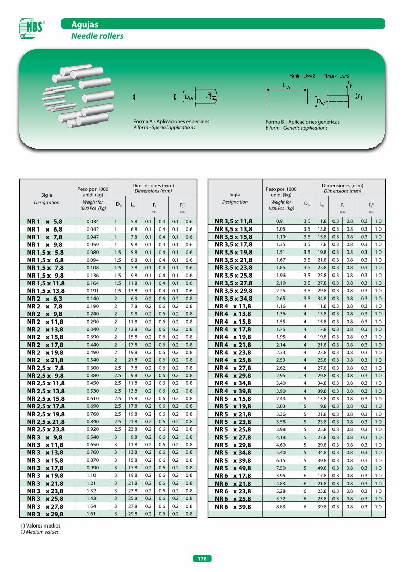
176
AgujasNeedle rollers
1) Valores medios1) Medium values
Dimensiones (mm)Dimensions (mm)
NR 1 x 5,8 NR 1 x 6,8 NR 1 x 7,8 NR 1 x 9,8 NR 1,5 x 5,8 NR 1,5 x 6,8 NR 1,5 x 7,8 NR 1,5 x 9,8 NR 1,5 x 11,8 NR 1,5 x 13,8 NR 2 x 6,3 NR 2 x 7,8 NR 2 x 9,8 NR 2 x 11,8 NR 2 x 13,8 NR 2 x 15,8 NR 2 x 17,8 NR 2 x 19,8 NR 2 x 21,8 NR 2,5 x 7,8 NR 2,5 x 9,8 NR 2,5 x 11,8 NR 2.5 x 13,8 NR 2,5 x 15,8 NR 2,5 x 17,8 NR 2,5 x 19,8 NR 2,5 x 21,8 NR 2,5 x 23,8 NR 3 x 9,8 NR 3 x 11,8 NR 3 x 13,8 NR 3 x 15,8 NR 3 x 17,8 NR 3 x 19,8 NR 3 x 21,8 NR 3 x 23,8 NR 3 x 25,8 NR 3 x 27,8 NR 3 x 29,8
0.034 1 5.8 0.1 0.4 0.1 0.6
0.042 1 6.8 0.1 0.4 0.1 0.6
0.047 1 7.8 0.1 0.4 0.1 0.6
0.059 1 9.8 0.1 0.4 0.1 0.6
0.080 1.5 5.8 0.1 0.4 0.1 0.6
0.094 1.5 6.8 0.1 0.4 0.1 0.6
0.108 1.5 7.8 0.1 0.4 0.1 0.6
0.136 1.5 9.8 0.1 0.4 0.1 0.6
0.164 1.5 11.8 0.1 0.4 0.1 0.6
0.191 1.5 13.8 0.1 0.4 0.1 0.6
0.140 2 6.3 0.2 0.6 0.2 0.8
0.190 2 7.8 0.2 0.6 0.2 0.8
0.240 2 9.8 0.2 0.6 0.2 0.8
0.290 2 11.8 0.2 0.6 0.2 0.8
0.340 2 13.8 0.2 0.6 0.2 0.8
0.390 2 15.8 0.2 0.6 0.2 0.8
0.440 2 17.8 0.2 0.6 0.2 0.8
0.490 2 19.8 0.2 0.6 0.2 0.8
0.540 2 21.8 0.2 0.6 0.2 0.8
0.300 2.5 7.8 0.2 0.6 0.2 0.8
0.380 2.5 9.8 0.2 0.6 0.2 0.8
0.450 2.5 11.8 0.2 0.6 0.2 0.8
0.530 2.5 13.8 0.2 0.6 0.2 0.8
0.610 2.5 15.8 0.2 0.6 0.2 0.8
0.690 2.5 17.8 0.2 0.6 0.2 0.8
0.760 2.5 19.8 0.2 0.6 0.2 0.8
0.840 2.5 21.8 0.2 0.6 0.2 0.8
0.920 2.5 23.8 0.2 0.6 0.2 0.8
0.540 3 9.8 0.2 0.6 0.2 0.8
0.650 3 11.8 0.2 0.6 0.2 0.8
0.760 3 13.8 0.2 0.6 0.2 0.8
0.870 3 15.8 0.2 0.6 0.2 0.8
0.990 3 17.8 0.2 0.6 0.2 0.8
1.10 3 19.8 0.2 0.6 0.2 0.8
1.21 3 21.8 0.2 0.6 0.2 0.8
1.32 3 23.8 0.2 0.6 0.2 0.8
1.43 3 25.8 0.2 0.6 0.2 0.8
1.54 3 27.8 0.2 0.6 0.2 0.8
1.61 3 29.8 0.2 0.6 0.2 0.8
SiglaDesignation Dw Lw r1
mín.
r21)
mín.
Peso por 1000 unid. (kg)Weight for
1000 Pcs (kg)
Dimensiones (mm)Dimensions (mm)
SiglaDesignation Dw Lw r1
mín.
r21)
mín.
Peso por 1000 unid. (kg)Weight for
1000 Pcs (kg)
NR 3,5 x 11,8 NR 3,5 x 13,8 NR 3,5 x 15,8 NR 3,5 x 17,8 NR 3,5 x 19,8 NR 3,5 x 21,8 NR 3,5 x 23,8 NR 3,5 x 25,8 NR 3,5 x 27.8 NR 3,5 x 29,8 NR 3,5 x 34,8 NR 4 x 11,8 NR 4 x 13,8 NR 4 x 15,8 NR 4 x 17,8 NR 4 x 19,8 NR 4 x 21,8 NR 4 x 23,8 NR 4 x 25,8 NR 4 x 27,8 NR 4 x 29,8 NR 4 x 34,8 NR 4 x 39,8 NR 5 x 15,8 NR 5 x 19,8 NR 5 x 21,8 NR 5 x 23,8 NR 5 x 25,8 NR 5 x 27,8 NR 5 x 29,8 NR 5 x 34,8 NR 5 x 39,8 NR 5 x 49,8 NR 6 x 17,8 NR 6 x 21,8 NR 6 x 23,8 NR 6 x 25,8 NR 6 x 39,8
0.91 3.5 11.8 0.3 0.8 0.3 1.0
1.05 3.5 13.8 0.3 0.8 0.3 1.0
1.19 3.5 15.8 0.3 0.8 0.3 1.0
1.35 3.5 17.8 0.3 0.8 0.3 1.0
1.51 3.5 19.8 0.3 0.8 0.3 1.0
1.67 3.5 21.8 0.3 0.8 0.3 1.0
1.85 3.5 23.8 0.3 0.8 0.3 1.0
1.96 3.5 25.8 0.3 0.8 0.3 1.0
2.10 3.5 27.8 0.3 0.8 0.3 1.0
2.25 3.5 29.8 0.3 0.8 0.3 1.0
2.65 3.5 34.8 0.3 0.8 0.3 1.0
1.16 4 11.8 0.3 0.8 0.3 1.0
1.36 4 13.8 0.3 0.8 0.3 1.0
1.55 4 15.8 0.3 0.8 0.3 1.0
1.75 4 17.8 0.3 0.8 0.3 1.0
1.95 4 19.8 0.3 0.8 0.3 1.0
2.14 4 21.8 0.3 0.8 0.3 1.0
2.33 4 23.8 0.3 0.8 0.3 1.0
2.53 4 25.8 0.3 0.8 0.3 1.0
2.62 4 27.8 0.3 0.8 0.3 1.0
2.95 4 29.8 0.3 0.8 0.3 1.0
3.40 4 34.8 0.3 0.8 0.3 1.0
3.90 4 39.8 0.3 0.8 0.3 1.0
2.43 5 15.8 0.3 0.8 0.3 1.0
3.03 5 19.8 0.3 0.8 0.3 1.0
3.36 5 21.8 0.3 0.8 0.3 1.0
3.58 5 23.8 0.3 0.8 0.3 1.0
3.98 5 25.8 0.3 0.8 0.3 1.0
4.18 5 27.8 0.3 0.8 0.3 1.0
4.60 5 29.8 0.3 0.8 0.3 1.0
5.40 5 34.8 0.3 0.8 0.3 1.0
6.15 5 39.8 0.3 0.8 0.3 1.0
7.50 5 49.8 0.3 0.8 0.3 1.0
3.95 6 17.8 0.3 0.8 0.3 1.0
4.83 6 21.8 0.3 0.8 0.3 1.0
5.28 6 23.8 0.3 0.8 0.3 1.0
5.72 6 25.8 0.3 0.8 0.3 1.0
8.83 6 39.8 0.3 0.8 0.3 1.0
Forma A - Aplicaciones especialesA form - Special applications
Forma B - Aplicaciones genéricasB form - Generic applications
ANILLOS OBTURADORES PARA MANGUITOS DE DESLIZAMIENTO (SERIE VB - VCW - VC)
SEALS FOR SLIDING BALL BUSHING (VB - VCW - VC SERIES)

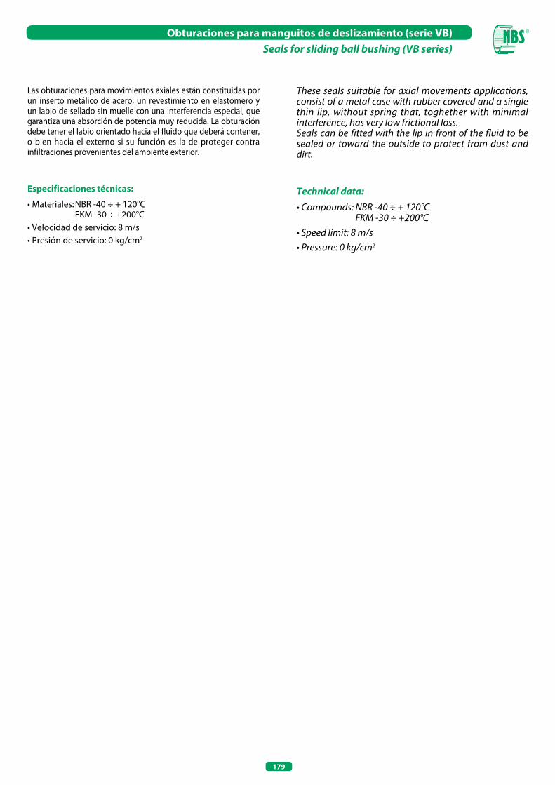
179
Obturaciones para manguitos de deslizamiento (serie VB)Seals for sliding ball bushing (VB series)
Las obturaciones para movimientos axiales están constituidas por un inserto metálico de acero, un revestimiento en elastomero y un labio de sellado sin muelle con una interferencia especial, que garantiza una absorción de potencia muy reducida. La obturación debe tener el labio orientado hacia el fluido que deberá contener, o bien hacia el externo si su función es la de proteger contra infiltraciones provenientes del ambiente exterior.
Especificaciones técnicas:
• Materiales: NBR -40 ÷ + 120°C FKM -30 ÷ +200°C• Velocidad de servicio: 8 m/s• Presión de servicio: 0 kg/cm2
These seals suitable for axial movements applications, consist of a metal case with rubber covered and a single thin lip, without spring that, toghether with minimal interference, has very low frictional loss.Seals can be fitted with the lip in front of the fluid to be sealed or toward the outside to protect from dust and dirt.
Technical data:• Compounds: NBR -40 ÷ + 120°C FKM -30 ÷ +200°C• Speed limit: 8 m/s• Pressure: 0 kg/cm2
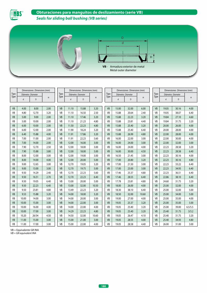
180
Obturaciones para manguitos de deslizamiento (serie VB)Seals for sliding ball bushing (VB series)
VB 4.00 8.00 2.00
VB 4.80 12.70 3.20
VB 5.00 9.00 2.00
VB 5.00 10.00 2.00
VB 6.00 10.00 2.00
VB 6.00 12.00 2.00
VB 6.40 15.88 4.00
VB 7.00 11.00 2.00
VB 7.00 14.00 2.00
VB 7.90 12.70 2.50
VB 7.90 15.88 3.80
VB 8.00 12.00 3.00
VB 8.00 14.00 4.00
VB 9.00 12.65 3.00
VB 9.00 13.00 3.00
VB 9.50 14.29 2.40
VB 9.50 16.51 2.70
VB 9.50 19.05 6.40
VB 9.50 22.23 6.40
VB 9.50 23.81 4.80
VB 9.53 15.88 3.20
VB 10.00 14.00 3.00
VB 10.00 15.00 3.00
VB 10.00 16.00 4.00
VB 10.00 17.00 3.00
VB 10.20 26/34 4.50
VB 11.00 15.00 3.00
VB 11.00 17.00 3.00
VB 11.10 15.88 3.20
VB 11.10 16.50 2.50
VB 11.10 17.46 3.20
VB 11.10 21.23 4.80
VB 11.50 22.23 4.80
VB 11.90 18.24 3.20
VB 11.91 17.86 3.20
VB 11.91 22.23 5.60
VB 12.00 16.00 3.00
VB 12.00 18.00 3.00
VB 12.00 18.00 5.00
VB 12.00 19.00 3.00
VB 12.00 20.00 5.00
VB 12.70 19.05 3.20
VB 12.70 19.75 5.00
VB 12.70 22.23 5.60
VB 12.70 22.23 6.40
VB 13.00 20.00 5.00
VB 13.00 32.00 10.50
VB 13.49 22.23 3.20
VB 14.00 18.00 3.20
VB 14.00 20.00 3.00
VB 14.00 22.00 3.00
VB 14.00 22.00 4.00
VB 14.29 22.23 4.80
VB 14.50 32.00 10.60
VB 15.00 21.00 3.00
VB 15.00 22.00 4.00
VB 15.00 32.00 6.00
VB 15.88 20.64 2.40
VB 15.88 22.23 3.20
VB 15.88 23.81 4.40
VB 15.88 25.40 3.20
VB 15.88 25.40 6.40
VB 15.88 26.99 4.80
VB 16.00 22.00 3.00
VB 16.00 24.00 3.00
VB 16.00 24.00 4.00
VB 16.00 30.00 4.50
VB 16.50 21.45 3.00
VB 17.00 20.80 3.20
VB 17.00 21.50 3.00
VB 17.00 23.00 3.00
VB 17.46 25.37 4.80
VB 17.46 28.55 6.40
VB 17.78 23.81 4.80
VB 18.00 26.00 4.00
VB 18.30 38.10 6.40
VB 18.50 32.00 10.60
VB 19.00 27.00 4.00
VB 19.05 25.37 3.20
VB 19.05 25.40 3.20
VB 19.05 25.40 3.20
VB 19.05 26.47 4.10
VB 19.05 28.55 4.00
VB 19.05 28.58 4.40
VB 19.05 30.16 4.00
VB 19.05 38.07 6.40
VB 19.84 27.10 4.60
VB 19.84 31.75 3.20
VB 20.00 26.00 4.00
VB 20.00 28.00 4.00
VB 22.00 28.00 4.00
VB 22.00 30.00 4.00
VB 22.00 32.00 3.00
VB 22.23 28.58 3.20
VB 22.23 28.58 6.40
VB 22.23 30.16 4.00
VB 22.23 30.16 4.80
VB 22.23 33.22 6.40
VB 22.23 34.93 6.40
VB 22.23 36.51 6.40
VB 22.86 38.10 6.40
VB 24.60 31.75 3.20
VB 25.00 32.00 4.00
VB 25.00 32.00 5.00
VB 25.00 34.00 5.00
VB 25.00 35.00 4.00
VB 25.00 35.00 5.00
VB 25.00 39.00 6.5/5.5
VB 25.40 31.75 3/3.2
VB 25.40 31.75 3.20
VB 25.40 34.93 4.80
VB 26.00 31.00 3.00
TipoType
Dimensiones Dimensions (mm)
Diámetro DiameterH
d D
TipoType
Dimensiones Dimensions (mm)
Diámetro DiameterH
d D
TipoType
Dimensiones Dimensions (mm)
Diámetro DiameterH
d D
TipoType
Dimensiones Dimensions (mm)
Diámetro DiameterH
d D
VB - Armadura exterior de metal Metal outer diameter
VB = Equivalente GR INAVB = GR equivalent INA
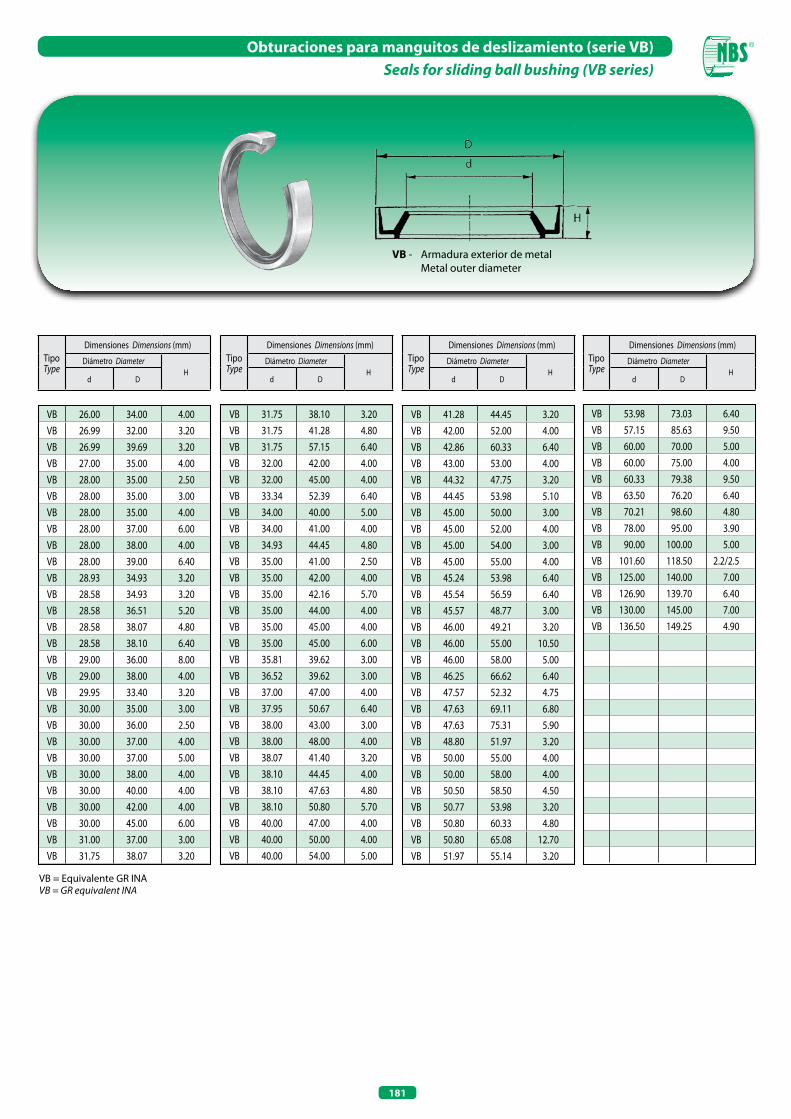
181
Obturaciones para manguitos de deslizamiento (serie VB)Seals for sliding ball bushing (VB series)
VB 26.00 34.00 4.00
VB 26.99 32.00 3.20
VB 26.99 39.69 3.20
VB 27.00 35.00 4.00
VB 28.00 35.00 2.50
VB 28.00 35.00 3.00
VB 28.00 35.00 4.00
VB 28.00 37.00 6.00
VB 28.00 38.00 4.00
VB 28.00 39.00 6.40
VB 28.93 34.93 3.20
VB 28.58 34.93 3.20
VB 28.58 36.51 5.20
VB 28.58 38.07 4.80
VB 28.58 38.10 6.40
VB 29.00 36.00 8.00
VB 29.00 38.00 4.00
VB 29.95 33.40 3.20
VB 30.00 35.00 3.00
VB 30.00 36.00 2.50
VB 30.00 37.00 4.00
VB 30.00 37.00 5.00
VB 30.00 38.00 4.00
VB 30.00 40.00 4.00
VB 30.00 42.00 4.00
VB 30.00 45.00 6.00
VB 31.00 37.00 3.00
VB 31.75 38.07 3.20
VB 31.75 38.10 3.20
VB 31.75 41.28 4.80
VB 31.75 57.15 6.40
VB 32.00 42.00 4.00
VB 32.00 45.00 4.00
VB 33.34 52.39 6.40
VB 34.00 40.00 5.00
VB 34.00 41.00 4.00
VB 34.93 44.45 4.80
VB 35.00 41.00 2.50
VB 35.00 42.00 4.00
VB 35.00 42.16 5.70
VB 35.00 44.00 4.00
VB 35.00 45.00 4.00
VB 35.00 45.00 6.00
VB 35.81 39.62 3.00
VB 36.52 39.62 3.00
VB 37.00 47.00 4.00
VB 37.95 50.67 6.40
VB 38.00 43.00 3.00
VB 38.00 48.00 4.00
VB 38.07 41.40 3.20
VB 38.10 44.45 4.00
VB 38.10 47.63 4.80
VB 38.10 50.80 5.70
VB 40.00 47.00 4.00
VB 40.00 50.00 4.00
VB 40.00 54.00 5.00
VB 41.28 44.45 3.20
VB 42.00 52.00 4.00
VB 42.86 60.33 6.40
VB 43.00 53.00 4.00
VB 44.32 47.75 3.20
VB 44.45 53.98 5.10
VB 45.00 50.00 3.00
VB 45.00 52.00 4.00
VB 45.00 54.00 3.00
VB 45.00 55.00 4.00
VB 45.24 53.98 6.40
VB 45.54 56.59 6.40
VB 45.57 48.77 3.00
VB 46.00 49.21 3.20
VB 46.00 55.00 10.50
VB 46.00 58.00 5.00
VB 46.25 66.62 6.40
VB 47.57 52.32 4.75
VB 47.63 69.11 6.80
VB 47.63 75.31 5.90
VB 48.80 51.97 3.20
VB 50.00 55.00 4.00
VB 50.00 58.00 4.00
VB 50.50 58.50 4.50
VB 50.77 53.98 3.20
VB 50.80 60.33 4.80
VB 50.80 65.08 12.70
VB 51.97 55.14 3.20
VB 53.98 73.03 6.40
VB 57.15 85.63 9.50
VB 60.00 70.00 5.00
VB 60.00 75.00 4.00
VB 60.33 79.38 9.50
VB 63.50 76.20 6.40
VB 70.21 98.60 4.80
VB 78.00 95.00 3.90
VB 90.00 100.00 5.00
VB 101.60 118.50 2.2/2.5
VB 125.00 140.00 7.00
VB 126.90 139.70 6.40
VB 130.00 145.00 7.00
VB 136.50 149.25 4.90
TipoType
Dimensiones Dimensions (mm)
Diámetro DiameterH
d D
TipoType
Dimensiones Dimensions (mm)
Diámetro DiameterH
d D
TipoType
Dimensiones Dimensions (mm)
Diámetro DiameterH
d D
TipoType
Dimensiones Dimensions (mm)
Diámetro DiameterH
d D
VB - Armadura exterior de metal Metal outer diameter
VB = Equivalente GR INAVB = GR equivalent INA
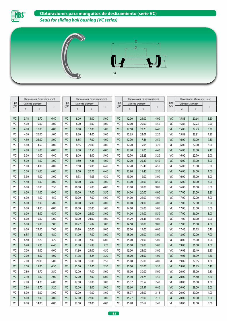
182
Obturaciones para manguitos de deslizamiento (serie VC)Seals for sliding ball bushing (VC series)
VC
VC 3.18 12.70 6.40
VC 4.00 9.00 3.00
VC 4.00 18.00 4.00
VC 4.50 26.00 5.00
VC 4.50 26.00 8.00
VC 4.80 14.50 4.00
VC 4.80 15.00 4.00
VC 5.00 10.00 4.00
VC 5.00 11.00 3.00
VC 5.00 14.00 4.00
VC 5.00 15.00 6.00
VC 5.50 9.00 3.00
VC 5.50 11.00 4.00
VC 6.00 10.00 2.50
VC 6.00 11.00 4.00
VC 6.00 11.00 4.50
VC 6.00 12.00 5.00
VC 6.00 14.00 4.00
VC 6.00 18.00 4.50
VC 6.00 19.00 5.00
VC 6.00 19.00 7.00
VC 6.00 22.00 7.00
VC 6.35 12.67 4.80
VC 6.40 12.70 3.20
VC 6.40 19.05 6.40
VC 7.00 13.00 4.00
VC 7.00 14.00 4.00
VC 7.00 20.00 5.00
VC 7.50 19.00 4.50
VC 7.80 13.70 2.50
VC 7.90 11.00 2.00
VC 7.90 14.28 6.00
VC 7.94 12.70 3.20
VC 8.00 12.00 3.00
VC 8.00 12.00 4.00
VC 8.00 14.00 4.00
VC 8.00 15.00 5.00
VC 8.00 16.00 4.00
VC 8.00 17.80 5.00
VC 8.60 14.00 3.00
VC 8.85 17.00 4.00
VC 8.85 20.00 4.00
VC 9.00 17.50 4.00
VC 9.00 18.00 5.00
VC 9.50 17.46 4.00
VC 9.50 19.05 6.40
VC 9.50 20.75 6.40
VC 9.53 19.05 4.30
VC 10.00 15.00 3.00
VC 10.00 15.00 4.00
VC 10.00 17.00 3.50
VC 10.00 17.00 5.00
VC 10.00 19.00 4.00
VC 10.00 20.00 5.00
VC 10.00 22.00 3.00
VC 10.00 24.00 4.00
VC 10.72 15.82 3.00
VC 10.80 20.00 9.00
VC 11.00 17.00 3.00
VC 11.00 17.00 6.00
VC 11.10 15.88 3.20
VC 11.90 25.00 4.50
VC 11.98 18.24 3.20
VC 12.00 16.00 2.50
VC 12.00 17.00 2.50
VC 12.00 17.00 5.00
VC 12.00 17.00 6.00
VC 12.00 18.00 3.00
VC 12.00 18.00 5.00
VC 12.00 19.00 3.00
VC 12.00 22.00 3.00
VC 12.00 22.00 4.00
VC 12.00 24.00 4.00
VC 12.00 25.00 4.50
VC 12.50 22.23 6.40
VC 12.65 23.01 2.20
VC 12.70 17.46 2.50
VC 12.70 19.05 3.20
VC 12.70 19.05 4.40
VC 12.70 22.23 3.20
VC 12.70 25.37 6.40
VC 12.70 25.40 4.50
VC 12.80 19.40 2.50
VC 13.00 19.00 3.00
VC 13.00 31.00 8.50
VC 13.00 32.00 9.00
VC 14.00 20.00 4.00
VC 14.00 22.00 4.00
VC 14.00 24.00 4.00
VC 14.00 25.00 5.00
VC 14.00 31.00 8.50
VC 14.29 24.41 5.00
VC 14.50 32.00 9.00
VC 15.00 19.00 6.00
VC 15.00 21.00 3.00
VC 15.00 21.00 5.00
VC 15.00 22.00 5.00
VC 15.00 23.00 3.00
VC 15.00 23.00 4.00
VC 15.00 25.00 4.00
VC 15.00 26.00 3.50
VC 15.00 30.00 5.00
VC 15.10 23.75 4.50
VC 15.32 20.57 2.40
VC 15.60 25.37 6.40
VC 15.77 26.00 2.16
VC 15.77 26.00 2.16
VC 15.88 20.64 2.40
VC 15.88 20.64 3.20
VC 15.88 22.23 2.50
VC 15.88 22.23 3.20
VC 15.88 23.81 4.80
VC 16.00 20.00 2.50
VC 16.00 22.00 3.00
VC 16.00 22.30 2.40
VC 16.00 22.70 2.00
VC 16.00 23.00 3.00
VC 16.00 23.00 5.00
VC 16.00 24.00 4.00
VC 16.00 25.00 5.00
VC 16.00 30.00 3.00
VC 16.00 30.00 5.00
VC 17.00 21.00 3.20
VC 17.00 22.00 5.00
VC 17.00 22.00 6.00
VC 17.00 23.00 3.00
VC 17.00 26.00 3.00
VC 17.00 30.00 5.00
VC 17.00 35.00 4.80
VC 17.46 31.75 6.40
VC 18.00 22.00 7.00
VC 18.00 24.00 4.00
VC 19.00 26.00 4.00
VC 19.05 25.40 3.20
VC 19.05 26.99 4.60
VC 19.05 27.05 4.60
VC 19.05 31.75 6.40
VC 20.00 25.00 2.50
VC 20.00 25.40 3.20
VC 20.00 26.00 4.00
VC 20.00 28.00 5.00
VC 20.00 30.00 4.00
VC 20.00 30.00 7.00
VC 20.00 32.00 5.00
TipoType
Dimensiones Dimensions (mm)
Diámetro DiameterH
d D
TipoType
Dimensiones Dimensions (mm)
Diámetro DiameterH
d D
TipoType
Dimensiones Dimensions (mm)
Diámetro DiameterH
d D
TipoType
Dimensiones Dimensions (mm)
Diámetro DiameterH
d D
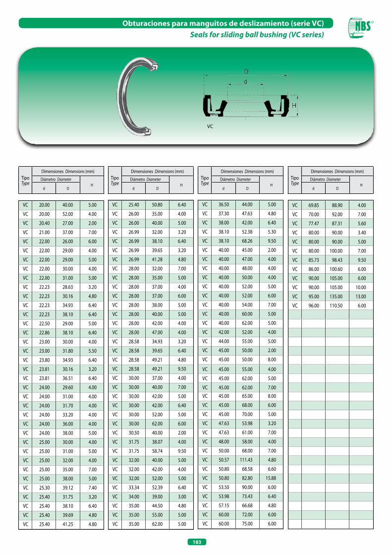
183
Obturaciones para manguitos de deslizamiento (serie VC)Seals for sliding ball bushing (VC series)
VC
TipoType
Dimensiones Dimensions (mm)
Diámetro DiameterH
d D
TipoType
Dimensiones Dimensions (mm)
Diámetro DiameterH
d D
TipoType
Dimensiones Dimensions (mm)
Diámetro DiameterH
d D
TipoType
Dimensiones Dimensions (mm)
Diámetro DiameterH
d D
VC 20.00 40.00 5.00
VC 20.00 52.00 4.00
VC 20.40 27.00 2.00
VC 21.00 37.00 7.00
VC 22.00 26.00 6.00
VC 22.00 29.00 4.00
VC 22.00 29.00 5.00
VC 22.00 30.00 4.00
VC 22.00 31.00 5.00
VC 22.23 28.63 3.20
VC 22.23 30.16 4.80
VC 22.23 34.93 6.40
VC 22.23 38.10 6.40
VC 22.50 29.00 5.00
VC 22.86 38.10 6.40
VC 23.00 30.00 4.00
VC 23.00 31.80 5.50
VC 23.80 34.93 6.40
VC 23.81 30.16 3.20
VC 23.81 36.51 6.40
VC 24.00 29.60 4.00
VC 24.00 31.00 4.00
VC 24.00 31.70 4.00
VC 24.00 33.20 4.00
VC 24.00 36.00 4.00
VC 24.00 38.00 5.00
VC 25.00 30.00 4.00
VC 25.00 31.00 5.00
VC 25.00 32.00 4.00
VC 25.00 35.00 7.00
VC 25.00 38.00 5.00
VC 25.30 39.12 7.40
VC 25.40 31.75 3.20
VC 25.40 38.10 6.40
VC 25.40 39.69 4.80
VC 25.40 41.25 4.80
VC 25.40 50.80 6.40
VC 26.00 35.00 4.00
VC 26.00 40.00 5.00
VC 26.99 32.00 3.20
VC 26.99 38.10 6.40
VC 26.99 39.65 3.20
VC 26.99 41.28 4.80
VC 28.00 32.00 7.00
VC 28.00 35.00 5.00
VC 28.00 37.00 4.00
VC 28.00 37.00 6.00
VC 28.00 38.00 5.00
VC 28.00 40.00 5.00
VC 28.00 42.00 4.00
VC 28.00 47.00 4.00
VC 28.58 34.93 3.20
VC 28.58 39.65 6.40
VC 28.58 49.21 4.80
VC 28.58 49.21 9.50
VC 30.00 37.00 4.00
VC 30.00 40.00 7.00
VC 30.00 42.00 5.00
VC 30.00 42.00 6.40
VC 30.00 52.00 5.00
VC 30.00 62.00 6.00
VC 30.50 40.00 2.00
VC 31.75 38.07 4.00
VC 31.75 58.74 9.50
VC 32.00 40.00 5.00
VC 32.00 42.00 4.00
VC 32.00 52.00 5.00
VC 33.34 52.39 6.40
VC 34.00 39.00 3.00
VC 35.00 44.50 4.80
VC 35.00 55.00 5.00
VC 35.00 62.00 5.00
VC 36.50 44.00 5.00
VC 37.30 47.63 4.80
VC 38.00 42.00 6.40
VC 38.10 52.38 5.30
VC 38.10 68.26 9.50
VC 40.00 45.00 2.00
VC 40.00 47.00 4.00
VC 40.00 48.00 4.00
VC 40.00 50.00 4.00
VC 40.00 52.00 5.00
VC 40.00 52.00 6.00
VC 40.00 54.00 7.00
VC 40.00 60.00 5.00
VC 40.00 62.00 5.00
VC 42.00 52.00 4.00
VC 44.00 55.00 5.00
VC 45.00 50.00 2.00
VC 45.00 50.00 8.00
VC 45.00 55.00 4.00
VC 45.00 62.00 5.00
VC 45.00 62.00 7.00
VC 45.00 65.00 8.00
VC 45.00 68.00 6.00
VC 45.00 70.00 5.00
VC 47.63 53.98 3.20
VC 47.63 61.00 7.00
VC 48.00 58.00 4.00
VC 50.00 68.00 7.00
VC 50.57 111.43 4.80
VC 50.80 68.58 6.60
VC 50.80 82.80 15.88
VC 53.50 90.00 6.00
VC 53.98 73.43 6.40
VC 57.15 66.68 4.80
VC 60.00 72.00 6.00
VC 60.00 75.00 6.00
VC 69.85 88.90 4.00
VC 70.00 92.00 7.00
VC 77.47 87.31 5.60
VC 80.00 90.00 3.40
VC 80.00 90.00 5.00
VC 80.00 100.00 7.00
VC 85.73 98.43 9.50
VC 86.00 100.60 6.00
VC 90.00 105.00 6.00
VC 90.00 105.00 10.00
VC 95.00 135.00 13.00
VC 96.00 110.50 6.00
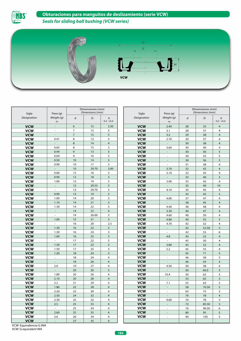
184
Obturaciones para manguitos de deslizamiento (serie VCW)Seals for sliding ball bushing (VCW series)
VCW
SiglaDesignation
Peso (g)Weight (g)
≈d D h
- 0.2 +0.4
Dimensiones (mm)Dimensions (mm) Sigla
DesignationPeso (g)
Weight (g)≈
d D h - 0.2 +0.4
Dimensiones (mm)Dimensions (mm)
VCW: Equivalencia G INAVCW: G equivalent INA
VCW VCW VCW VCW VCW VCW VCW VCW VCW VCW VCW VCW VCW VCW VCW VCW VCW VCW VCW VCW VCW VCW VCW VCW VCW VCW VCW VCW VCW VCW VCW VCW VCW VCW VCW VCW VCW VCW VCW VCW VCW VCW VCW VCW VCW VCW VCW
-
-
-
0.41
-
0.65
0.44
0.69
0.50
0.90
-
0.60
0.90
1.00
-
-
0.90
1.00
1.10
1.30
-
-
1.00
-
1.30
1.30
1.60
-
1.30
1.50
1.20
-
-
2.0
-
1.80
2.10
2.2
1.80
2.20
2.50
2.30
2.5
-
2.60
2.6
-
6 15 3.30
7 15 3
7 15 5
8 12 3
8 14 4
8 15 3
9 13 3
9 16 3
10 14 3
10 17 3
10 29.70 3.00
12 16 3
12 18 3
12 19 3
12 29.55 3
12 29.70 3
13 19 3
14 20 3
14 21 3
14 22 3
14 22 4
14 26.00 3
15 21 3
16 20 2.5
16 22 3
16 24 3
16 25 3
17 22 5
17 23 3
17 25 3
18 24 3
18 24 4
18 26 4
19 27 4
20 26 3
20 26 4
20 28 4
21 29 4
22 28 4
22 30 4
24 32 4
25 32 4
25 33 4
25 34 4
25 35 4
26 34 4
27 35 4
28 35 4
28 37 4
29 38 4
30 37 4
30 38 4
30 40 4
30 50 5
30 55 5
30 56 5
31 38 4
32 42 4
32 45 4
33 40 3
35 42 4
35 40 10
35 45 4
35 45 5
37 47 4
38 45 4
38 48 4
40 47 4
40 50 4
40 52 5
42 52 4
42 52.50 5
42 55 6
43 53 4
45 50 4
45 52 4
45 55 4
45 71 5
46 58 5
46 54 4
50 58 4
50 60.5 5
50 62 5
53 65 5
55 63 5
58 70.50 5
63 75 5
70 78 4
70 78 5
72 85.50 5
76 90.50 6
80 95 5
90 105 5
2.40
3.1
3.2
2.70
-
3.60
-
-
-
-
3.70
5.10
-
3.00
-
4.10
-
4.00
-
4.40
3.30
4.60
4.80
4.70
-
-
4.8
-
3.80
5.2
-
-
-
4.50
-
10.4
-
7.1
-
-
-
9.00
-
-
-
-
VCW VCW VCW VCW VCW VCW VCW VCW VCW VCW VCW VCW VCW VCW VCW VCW VCW VCW VCW VCW VCW VCW VCW VCW VCW VCW VCW VCW VCW VCW VCW VCW VCW VCW VCW VCW VCW VCW VCW VCW VCW VCW VCW VCW VCW VCW
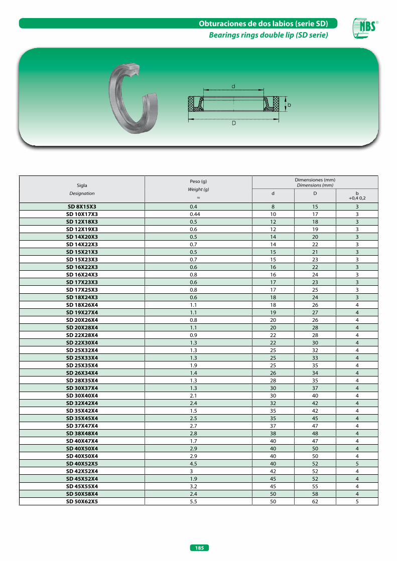
185
Obturaciones de dos labios (serie SD)Bearings rings double lip (SD serie)
Sigla
Designation
Peso (g)
Weight (g)
≈
Dimensiones (mm)Dimensions (mm)
d D b+0,4 0,2
SD 8x15x3 0.4 8 15 3SD 10x17x3 0.44 10 17 3SD 12x18x3 0.5 12 18 3SD 12x19x3 0.6 12 19 3SD 14x20x3 0.5 14 20 3SD 14x22x3 0.7 14 22 3SD 15x21x3 0.5 15 21 3SD 15x23x3 0.7 15 23 3SD 16x22x3 0.6 16 22 3SD 16x24x3 0.8 16 24 3SD 17x23x3 0.6 17 23 3SD 17x25x3 0.8 17 25 3SD 18x24x3 0.6 18 24 3SD 18x26x4 1.1 18 26 4SD 19x27x4 1.1 19 27 4SD 20x26x4 0.8 20 26 4SD 20x28x4 1.1 20 28 4SD 22x28x4 0.9 22 28 4SD 22x30x4 1.3 22 30 4SD 25x32x4 1.3 25 32 4SD 25x33x4 1.3 25 33 4SD 25x35x4 1.9 25 35 4SD 26x34x4 1.4 26 34 4 SD 28x35x4 1.3 28 35 4SD 30x37x4 1.3 30 37 4SD 30x40x4 2.1 30 40 4SD 32x42x4 2.4 32 42 4SD 35x42x4 1.5 35 42 4SD 35x45x4 2.5 35 45 4SD 37x47x4 2.7 37 47 4SD 38x48x4 2.8 38 48 4SD 40x47x4 1.7 40 47 4SD 40x50x4 2.9 40 50 4SD 40x50x4 2.9 40 50 4SD 40x52x5 4.5 40 52 5SD 42x52x4 3 42 52 4SD 45x52x4 1.9 45 52 4SD 45x55x4 3.2 45 55 4SD 50x58x4 2.4 50 58 4SD 50x62x5 5.5 50 62 5

ANILLOS ELÁSTICOSELASTIC RINGS

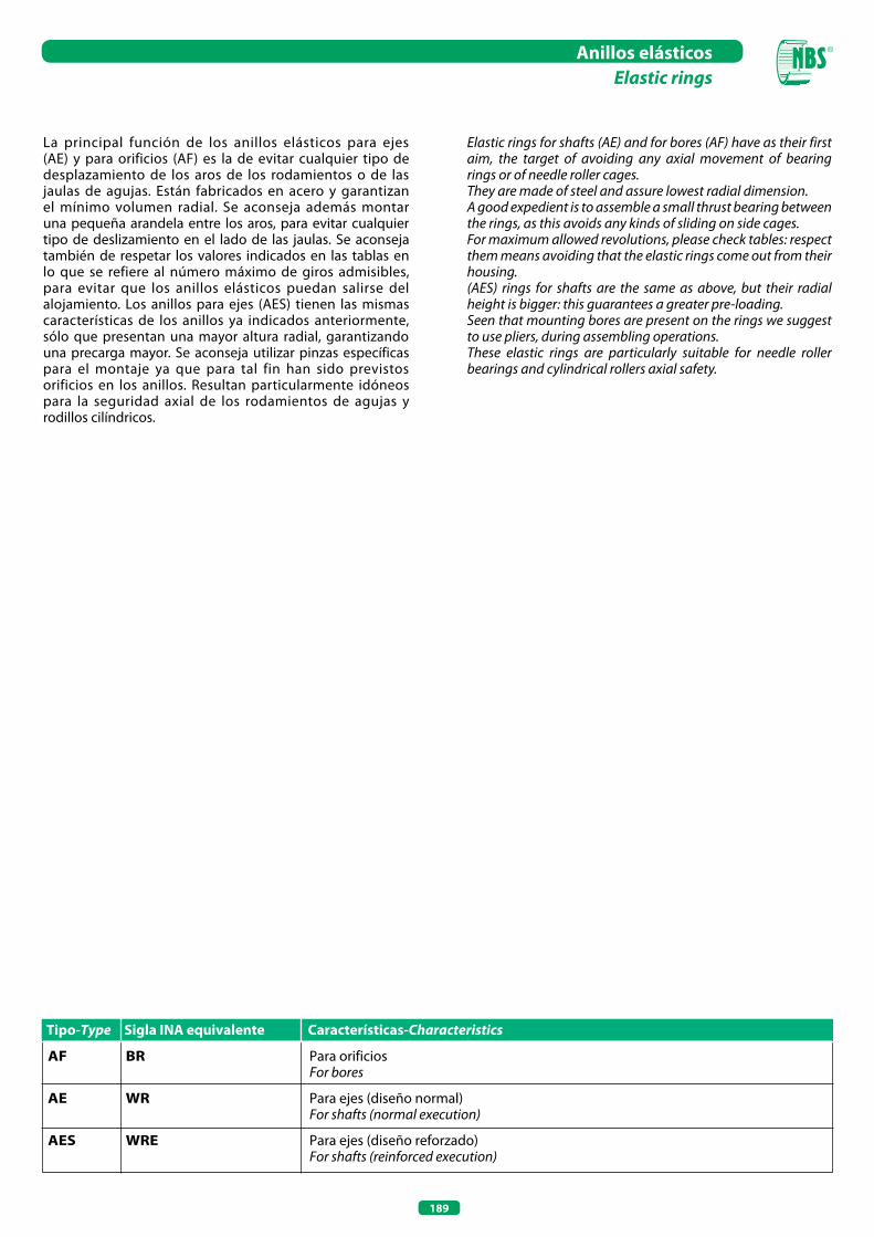
189
Anillos elásticosElastic rings
La principal función de los anillos elásticos para ejes (AE) y para orificios (AF) es la de evitar cualquier tipo de desplazamiento de los aros de los rodamientos o de las jaulas de agujas. Están fabricados en acero y garantizan el mínimo volumen radial. Se aconseja además montar una pequeña arandela entre los aros, para evitar cualquier tipo de deslizamiento en el lado de las jaulas. Se aconseja también de respetar los valores indicados en las tablas en lo que se refiere al número máximo de giros admisibles, para evitar que los anillos elásticos puedan salirse del alojamiento. Los anillos para ejes (AES) tienen las mismas características de los anillos ya indicados anteriormente, sólo que presentan una mayor altura radial, garantizando una precarga mayor. Se aconseja utilizar pinzas específicas para el montaje ya que para tal fin han sido previstos orificios en los anillos. Resultan particularmente idóneos para la seguridad axial de los rodamientos de agujas y rodillos cilíndricos.
AF BR Para orificios For bores
AE WR Para ejes (diseño normal) For shafts (normal execution)
AES WRE Para ejes (diseño reforzado) For shafts (reinforced execution)
Tipo-Type Sigla INA equivalente Características-Characteristics
Elastic rings for shafts (AE) and for bores (AF) have as their first aim, the target of avoiding any axial movement of bearing rings or of needle roller cages.They are made of steel and assure lowest radial dimension.A good expedient is to assemble a small thrust bearing between the rings, as this avoids any kinds of sliding on side cages.For maximum allowed revolutions, please check tables: respect them means avoiding that the elastic rings come out from their housing.(AES) rings for shafts are the same as above, but their radial height is bigger: this guarantees a greater pre-loading.Seen that mounting bores are present on the rings we suggest to use pliers, during assembling operations.These elastic rings are particularly suitable for needle roller bearings and cylindrical rollers axial safety.
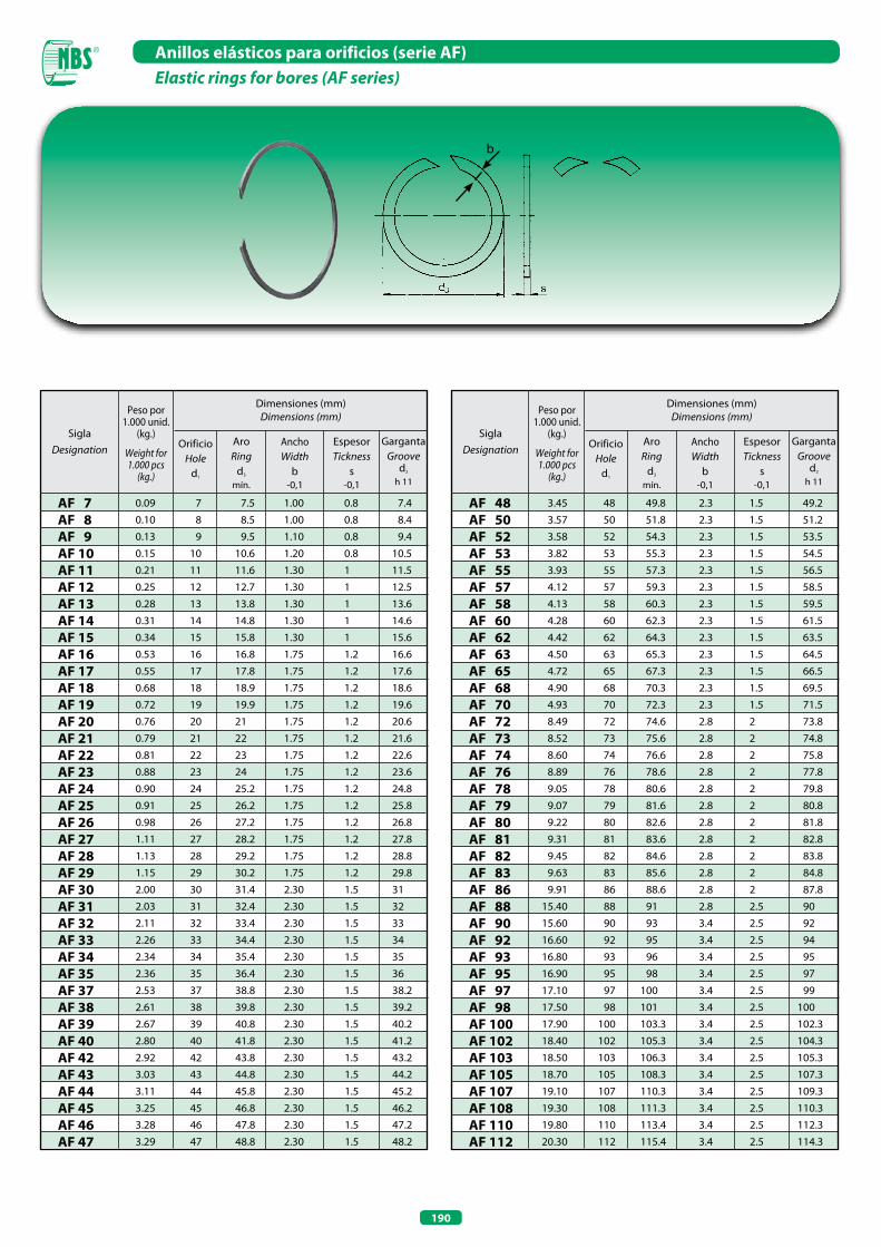
190
Anillos elásticos para orificios (serie AF)Elastic rings for bores (AF series)
b
Dimensiones (mm)Dimensions (mm)
AF 7AF 8AF 9AF 10AF 11AF 12AF 13AF 14AF 15AF 16AF 17AF 18AF 19AF 20AF 21AF 22AF 23AF 24AF 25AF 26AF 27AF 28AF 29AF 30AF 31AF 32AF 33AF 34AF 35AF 37AF 38AF 39AF 40AF 42AF 43AF 44AF 45AF 46AF 47
7 7.5 0.8 7.4
8 8.5 0.8 8.4
9 9.5 0.8 9.4
10 10.6 0.8 10.5
11 11.6 1 11.5
12 12.7 1 12.5
13 13.8 1 13.6
14 14.8 1 14.6
15 15.8 1 15.6
16 16.8 1.2 16.6
17 17.8 1.2 17.6
18 18.9 1.2 18.6
19 19.9 1.2 19.6
20 21 1.2 20.6
21 22 1.2 21.6
22 23 1.2 22.6
23 24 1.2 23.6
24 25.2 1.2 24.8
25 26.2 1.2 25.8
26 27.2 1.2 26.8
27 28.2 1.2 27.8
28 29.2 1.2 28.8
29 30.2 1.2 29.8
30 31.4 1.5 31
31 32.4 1.5 32
32 33.4 1.5 33
33 34.4 1.5 34
34 35.4 1.5 35
35 36.4 1.5 36
37 38.8 1.5 38.2
38 39.8 1.5 39.2
39 40.8 1.5 40.2
40 41.8 1.5 41.2
42 43.8 1.5 43.2
43 44.8 1.5 44.2
44 45.8 1.5 45.2
45 46.8 1.5 46.2
46 47.8 1.5 47.2
47 48.8 1.5 48.2
Peso por 1.000 unid.
(kg.)
Weight for 1.000 pcs
(kg.)
SiglaDesignation
0.09
0.10
0.13
0.15
0.21
0.25
0.28
0.31
0.34
0.53
0.55
0.68
0.72
0.76
0.79
0.81
0.88
0.90
0.91
0.98
1.11
1.13
1.15
2.00
2.03
2.11
2.26
2.34
2.36
2.53
2.61
2.67
2.80
2.92
3.03
3.11
3.25
3.28
3.29
1.00
1.00
1.10
1.20
1.30
1.30
1.30
1.30
1.30
1.75
1.75
1.75
1.75
1.75
1.75
1.75
1.75
1.75
1.75
1.75
1.75
1.75
1.75
2.30
2.30
2.30
2.30
2.30
2.30
2.30
2.30
2.30
2.30
2.30
2.30
2.30
2.30
2.30
2.30
Dimensiones (mm)Dimensions (mm)
Peso por 1.000 unid.
(kg.)
Weight for 1.000 pcs
(kg.)
SiglaDesignation
3.45
3.57
3.58
3.82
3.93
4.12
4.13
4.28
4.42
4.50
4.72
4.90
4.93
8.49
8.52
8.60
8.89
9.05
9.07
9.22
9.31
9.45
9.63
9.91
15.40
15.60
16.60
16.80
16.90
17.10
17.50
17.90
18.40
18.50
18.70
19.10
19.30
19.80
20.30
2.3
2.3
2.3
2.3
2.3
2.3
2.3
2.3
2.3
2.3
2.3
2.3
2.3
2.8
2.8
2.8
2.8
2.8
2.8
2.8
2.8
2.8
2.8
2.8
2.8
3.4
3.4
3.4
3.4
3.4
3.4
3.4
3.4
3.4
3.4
3.4
3.4
3.4
3.4
AF 48AF 50AF 52AF 53AF 55AF 57AF 58AF 60AF 62AF 63AF 65AF 68AF 70AF 72AF 73AF 74AF 76AF 78AF 79AF 80AF 81AF 82AF 83AF 86AF 88AF 90AF 92AF 93AF 95AF 97AF 98AF 100AF 102AF 103AF 105AF 107AF 108AF 110AF 112
AroRing
d3
mín.
AnchoWidth
b-0,1
EspesorTickness
s-0,1
GargantaGroove
d2
h 11
OrificioHole
d1
AroRing
d3
mín.
AnchoWidth
b-0,1
EspesorTickness
s-0,1
GargantaGroove
d2
h 11
OrificioHole
d1
48 49.8 1.5 49.2
50 51.8 1.5 51.2
52 54.3 1.5 53.5
53 55.3 1.5 54.5
55 57.3 1.5 56.5
57 59.3 1.5 58.5
58 60.3 1.5 59.5
60 62.3 1.5 61.5
62 64.3 1.5 63.5
63 65.3 1.5 64.5
65 67.3 1.5 66.5
68 70.3 1.5 69.5
70 72.3 1.5 71.5
72 74.6 2 73.8
73 75.6 2 74.8
74 76.6 2 75.8
76 78.6 2 77.8
78 80.6 2 79.8
79 81.6 2 80.8
80 82.6 2 81.8
81 83.6 2 82.8
82 84.6 2 83.8
83 85.6 2 84.8
86 88.6 2 87.8
88 91 2.5 90
90 93 2.5 92
92 95 2.5 94
93 96 2.5 95
95 98 2.5 97
97 100 2.5 99
98 101 2.5 100
100 103.3 2.5 102.3
102 105.3 2.5 104.3
103 106.3 2.5 105.3
105 108.3 2.5 107.3
107 110.3 2.5 109.3
108 111.3 2.5 110.3
110 113.4 2.5 112.3
112 115.4 2.5 114.3

191
Anillos elásticos para orificios (serie AF)Elastic rings for bores (AF series)
b
Dimensiones de montajeMounting dimension
Dimensiones (mm)Dimensions (mm)
AF 113AF 115AF 117AF 118AF 120AF 123AF 125AF 127AF 130AF 133AF 135AF 137AF 140AF 143AF 150AF 153AF 160AF 163AF 165AF 170AF 173AF 175
Peso por 1.000 unid.
(kg.)
Weight for 1.000 pcs
(kg.)
SiglaDesignation
20.50
20.60
20.80
21.10
21.40
22.00
22.50
23.00
23.40
24.40
25.00
25.30
29.30
30.10
31.90
32.60
34.40
34.60
34.90
36.20
37.10
37.30
3.4
3.4
3.4
3.4
3.4
3.4
3.4
3.4
3.4
3.4
3.4
3.4
4.0
4.0
4.0
4.0
4.0
4.0
4.0
4.0
4.0
4.0
Dimensiones (mm)Dimensions (mm)Peso por
1.000 unid.(kg.)
Weight for 1.000 pcs
(kg.)
SiglaDesignation
38.30
41.00
61.30
61.60
64.50
66.40
72.40
75.20
84.20
174.0
184.0
196.0
203.0
206.0
231.0
240.0
248.0
257.0
260.0
277.0
294.0
4.0
4.0
5.0
5.0
5.0
5.0
5.0
5.0
5.0
7.5
7.5
7.5
7.5
7.5
7.5
7.5
7.5
7.5
7.5
7.5
7.5
AF 180AF 183AF 190AF 195AF 200AF 205AF 220AF 230AF 250AF 270AF 280AF 300AF 320AF 325AF 355AF 375AF 385AF 395AF 400AF 420AF 440
AroRing
d3
mín.
AnchoWidth
b-0.1
EspesorTickness
s-0.1
GargantaGroove
d2
h 11
OrificioHole
d1
AroRing
d3
mín.
AnchoWidth
b-0,1
EspesorTickness
s-0,1
GargantaGroove
d2
h 11
OrificioHole
d1
113 116.4 2.5 115.3
115 118.4 2.5 117.3
117 120.4 2.5 119.3
118 121.4 2.5 120.3
120 123.6 2.5 122.3
123 126.6 2.5 125.3
125 128.6 2.5 127.3
127 130.6 2.5 129.3
130 133.7 2.5 132.3
133 136.7 2.5 135.3
135 138.7 2.5 137.3
137 140.7 2.5 139.3
140 144.1 2.5 142.6
143 147.1 2.5 145.6
150 154.2 2.5 152.6
153 157.2 2.5 155.6
160 164.3 2.5 162.6
163 167.3 2.5 165.6
165 169.3 2.5 167.6
170 174.4 2.5 172.6
173 177.4 2.5 175.6
175 179.4 2.5 177.6
180 184.5 2.5 182.6
183 187.5 2.5 185.6
190 194.9 3 193
195 199.9 3 198
200 205 3 203
205 210 3 208
220 225.2 3 223
230 235.3 3 233
250 255.5 3 253
270 277.7 4 275
280 287.8 4 285
300 307.9 4 305
320 328.2 4 325
325 333.2 4 330
355 363.4 4 360
375 383.6 4 380
385 393.7 4 390
395 403.8 4 400
400 408.9 4 405
420 429.1 4 425
440 449.3 4 445

192
Anillos elásticos para ejes diseño normal (serie AE)Elastic rings for shafts normal execution (AE series)
b
d3 s
Dimensiones (mm)Dimensions (mm)
AE 90AE 95AE 100AE 105AE 110AE 115AE 120AE 125AE 130AE 135AE 140AE 145AE 150AE 155AE 160AE 165AE 170AE 175AE 180AE 185AE 190AE 195AE 200AE 210AE 220AE 225AE 230AE 240AE 260
Peso por 1.000 unid.
(kg.)
Weight for 1.000 pcs
(kg.)
SiglaDesignation
16.0018.2018.9020.7020.9022.1024.1025.1026.6030.2031.1032.6032.8034.7036.6037.4038.5039.4061.2063.9065.9067.5068.4072.0076.3078.0079.8081.70179.0
AroRing
d3
máx.
AnchoWidth
b-0,1
EspesorTickness
s-0,1
GargantaGroove
d2
h 11
OrificioHole
d1
3.403.403.403.403.403.403.403.403.404.004.004.004.004.004.004.004.004.005.005.005.005.005.005.005.005.005.005.007.50
90 87 2.5 88 95 92 2.5 93 100 97 2.5 98 105 101.7 2.5 102.7 110 106.6 2.5 107.7 115 111.6 2.5 112.7 120 116.5 2.5 117.7 125 121.4 2.5 122.7 130 126.3 2.5 127.7 135 131 2.5 132.4 140 135.9 2.5 137.4 145 140.9 2.5 142.4 150 145.8 2.5 147.4 155 150.8 2.5 152.4 160 155.7 2.5 157.4 165 160.7 2.5 162.4 170 165.6 2.5 167.4 175 170.6 2.5 172.4 180 175.2 3 177 185 180.1 3 182 190 185.1 3 187 195 190.1 3 192 200 195 3 197 210 204.9 3 207 220 214.8 3 217 225 219.8 3 222 230 224.7 3 227 240 234.6 3 237 260 252.4 4 255
Dimensiones (mm)Dimensions (mm)
AE 4AE 5AE 6AE 7AE 8AE 9AE 10AE 11AE 12AE 14AE 15AE 16AE 17AE 18AE 19AE 20AE 21AE 22AE 24AE 25AE 26AE 28AE 29AE 30AE 32AE 35AE 37AE 38AE 40
Peso por 1.000 unid.
(kg.)
Weight for 1.000 pcs
(kg.)
SiglaDesignation
0.02 0.05 0.09 0.12 0.20 0.24 0.25 0.29 0.30 0.50 0.66 0.69 0.72 0.75 0.80 0.84 0.87 0.91 0.99 1.00 1.10 2.11 2.20 2.33 2.41 2.51 2.72 2.83 2.91
AroRing
d3
máx.
AnchoWidth
b-0,1
EspesorTickness
s-0,1
GargantaGroove
d2
h 11
OrificioHole
d1
4 3.7 0.5 3.8 5 4.7 0.5 4.8 6 5.6 0.7 5.7 7 6.5 0.7 6.7 8 7.4 1 7.6 9 8.4 1 8.6 10 9.4 1 9.6 11 10.2 1 10.5 12 11.2 1 11.5 14 13.1 1.2 13.5 15 14 1.2 14.4 16 15 1.2 15.4 17 16 1.2 16.4 18 17 1.2 17.4 19 17.9 1.2 18.4 20 18.7 1.2 19.2 21 19.7 1.2 20.2 22 20.7 1.2 21.2 24 22.5 1.2 23 25 23.5 1.2 24 26 24.5 1.2 25 28 26.5 1.5 27 29 27.5 1.5 28 30 28.5 1.5 29 32 30.2 1.5 30.8 35 33.2 1.5 33.8 37 35.2 1.5 35.8 38 36.2 1.5 36.8 40 37.8 1.5 38.5
0.801.001.101.201.301.301.301.301.301.501.751.751.751.751.751.751.751.751.751.751.752.302.302.302.302.302.302.302.30
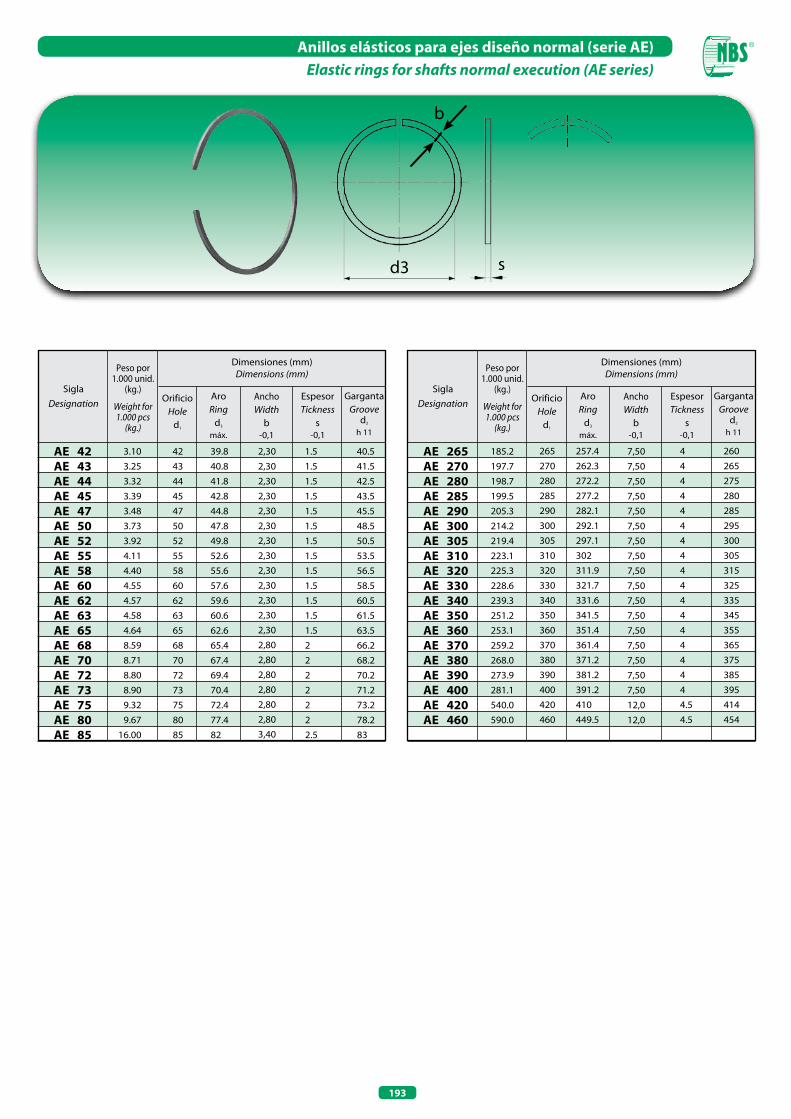
193
Anillos elásticos para ejes diseño normal (serie AE)Elastic rings for shafts normal execution (AE series)
b
d3 s
Dimensiones (mm)Dimensions (mm)
AE 42AE 43AE 44AE 45AE 47AE 50AE 52AE 55AE 58AE 60AE 62AE 63AE 65AE 68AE 70AE 72AE 73AE 75AE 80AE 85
Peso por 1.000 unid.
(kg.)
Weight for 1.000 pcs
(kg.)
SiglaDesignation
3.10 3.25 3.32 3.39 3.48 3.73 3.92 4.11 4.40 4.55 4.57 4.58 4.64 8.59 8.71 8.80 8.90 9.32 9.67 16.00
AroRing
d3
máx.
AnchoWidth
b-0,1
EspesorTickness
s-0,1
GargantaGroove
d2
h 11
OrificioHole
d1
42 39.8 1.5 40.5 43 40.8 1.5 41.5 44 41.8 1.5 42.5 45 42.8 1.5 43.5 47 44.8 1.5 45.5 50 47.8 1.5 48.5 52 49.8 1.5 50.5 55 52.6 1.5 53.5 58 55.6 1.5 56.5 60 57.6 1.5 58.5 62 59.6 1.5 60.5 63 60.6 1.5 61.5 65 62.6 1.5 63.5 68 65.4 2 66.2 70 67.4 2 68.2 72 69.4 2 70.2 73 70.4 2 71.2 75 72.4 2 73.2 80 77.4 2 78.2 85 82 2.5 83
2,302,302,302,302,302,302,302,302,302,302,302,302,302,802,802,802,802,802,803,40
Dimensiones (mm)Dimensions (mm)
AE 265AE 270AE 280AE 285AE 290AE 300AE 305AE 310AE 320AE 330AE 340AE 350AE 360AE 370AE 380AE 390AE 400AE 420AE 460
Peso por 1.000 unid.
(kg.)
Weight for 1.000 pcs
(kg.)
SiglaDesignation
185.2197.7198.7199.5205.3214.2219.4223.1225.3228.6239.3251.2253.1259.2268.0273.9281.1540.0590.0
AroRing
d3
máx.
AnchoWidth
b-0,1
EspesorTickness
s-0,1
GargantaGroove
d2
h 11
OrificioHole
d1
7,507,507,507,507,507,507,507,507,507,507,507,507,507,507,507,507,5012,012,0
265 257.4 4 260 270 262.3 4 265 280 272.2 4 275 285 277.2 4 280 290 282.1 4 285 300 292.1 4 295 305 297.1 4 300 310 302 4 305 320 311.9 4 315 330 321.7 4 325 340 331.6 4 335 350 341.5 4 345 360 351.4 4 355 370 361.4 4 365 380 371.2 4 375 390 381.2 4 385 400 391.2 4 395 420 410 4.5 414 460 449.5 4.5 454
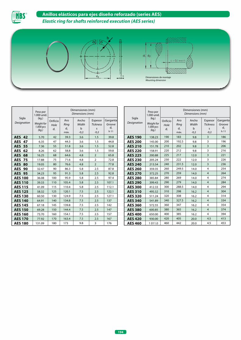
194
Anillos elásticos para ejes diseño reforzado (series AES)Elastic ring for shafts reinforced execution (AES series)
Dimensiones de montajeMounting dimension
b
Dimensiones (mm)Dimensions (mm)
AES 42AES 47AES 55AES 62AES 68AES 75AES 80AES 90AES 95AES 100AES 110AES 115AES 125AES 130AES 140AES 145AES 150AES 160AES 170AES 180
Peso por 1.000 unid.
(kg.)
Weight for 1.000 pcs
(kg.)
SiglaDesignation
5.70 6.35 7.36 8.26 16.25 17.88 19.05 32.47 34.23 36.08 39.33 41.09 58.32 60.50 64.91 67.18 69.28 73.70 77.92 131.09
AroRing
d3
máx.
AnchoWidth
b-0,2
EspesorTickness
s-0,2
GargantaGroove
d2
h 11
OrificioHole
d1
3.63.63.63.64.84.84.85.85.85.85.85.87.57.57.57.57.57.57.59.8
Dimensiones (mm)Dimensions (mm)
AES 190AES 200AES 210AES 220AES 225AES 230AES 240AES 260AES 270AES 280AES 290AES 300AES 310AES 320AES 340AES 360AES 380AES 400AES 420AES 460
Peso por 1.000 unid.
(kg.)
Weight for 1.000 pcs
(kg.)
SiglaDesignation
138.23 145.00 151.78 158.91 200.88 205.24 213.54 359.35 372.25 385.84 399.43 412.33 495.52 511.24 541.89 572.55 600.85 650.00 930.00 1 011.0
AroRing
d3
máx.
AnchoWidth
b-0,2
EspesorTickness
s-0,2
GargantaGroove
d2
h 11
OrificioHole
d1
9.8 9.8 9.8 9.812.012.012.014.014.014.014.014.016.216.216.216.216.216.220.020.0
190 183 3 186 200 192.5 3 196 210 202 3 206 220 212 3 216 225 217 3 221 230 222 3 226 240 231.5 3 236 260 249.5 4 254 270 259 4 264 280 269 4 274 290 279 4 284 300 288.5 4 294 310 298 4 304 320 308 4 314 340 327.5 4 334 360 347 4 354 380 365 4 374 400 385 4 394 420 405 4.5 413 460 442 4.5 453
42 39.3 1.5 39.8 47 44.3 1.5 44.8 55 51.8 1.5 52.8 62 58.8 1.5 59.8 68 64.6 2 65.8 75 71.6 2 72.8 80 76.6 2 77.8 90 86.3 2.5 87.8 95 91.3 2.5 92.8 100 95.9 2.5 97.4 110 105.4 2.5 107.1 115 110.4 2.5 112.1 125 120.1 2.5 122.1 130 124.9 2.5 127.1 140 134.8 2.5 137 145 139.8 2.5 142 150 144.4 2.5 147 160 154.1 2.5 157 170 163.4 2.5 167 180 173 3 176
RODAMIENTOS PARA SISTEMAS LINEALESLINEAR BEARINGS


197
Características técnicasLos productos NBS para sistemas lineales han sido ideados para ofrecer buenas prestaciones, manteniendo un mínimo coeficiente de fricción. Encuentran aplicación en múltiples campos, como por ejemplo las partes móviles de las máquinas empacadoras, máquinas herramientas, máquinas para la elaboración del aluminio y de la madera, sistemas de protección y revestimiento, robots, sistemas de posicionamiento e instrumentos de medición y control.
Technical characteristicsNBS linear bearings have been made to offer a good performance by keeping a minimum friction coefficient.They apply to different sectors, such as package machines, tool machines, wood and aluminium working machines, protection and covering systems, robots, positioning systems and measurement instruments too.

198
Capacidad de carga y vida útil
La capacidad de carga está definida por las condiciones de:
• Carga estática• Carga dinámica
Carga estáticaEl índice utilizado para evaluar la capacidad de un sistema lineal para absorber las cargas y/o los momentos estáticos es la:
• Capacidad de carga estática C0
Se denomina capacidad de carga estática C0 (o coeficiente de carga estática) a la carga estática, con intensidad y dirección constantes, que determina, en el punto de máxima solicitación entre las partes a contacto, una deformación permanente equivalente a 1/10000 del diámetro del elemento rodante.
Los valores de C0 están expuestos en las tablas dimensionales.
Coeficiente de seguridad estático aS
El coeficiente de seguridad estático aS (o factor de seguridad estática) está dado por la siguiente relación:
donde:aS = coeficiente de seguridad estáticofC = factor de contactofB = coeficiente de layout recirculacionesC0 = capacidad de carga estática [N]P = carga máxima aplicada [N]
A continuación se definen los factores fC y fB :
Factor de contacto fC
Si se montan dos o más casquillos en una misma guía, la durabilidad podría verse penalizada por la falta de uniformidad en la distribución de las cargas aplicadas sobre los casquillos mismos.
Tabla - Factor de contacto fC
Número de casquillos por cada ejeNumber of linear bearings for shaft fC
1
2
3
4
5
1.0
0.81
0.72
0.66
0.61
Load rating and life
Load rating is defined for conditions of:
• Static load• Dynamic load
Static loadThe index used to value the static load capacity for a linear system is:
• Static load rating capacity C0
Static load rating capacity C0 is defined as the constant load rating that generates a remaining deformation of 1/10000 of the rolling element diameter in the zone with the maximum stress.
C0 values are shown on dimensional tables.
Static safety factor aS
Static safety factor is calculated through the following formula:
where:aS = static safety factorfC = contact factor fB = layout factorC0 = static load rating capacity [N]P = maximum load applied [N]
Definition of fC and fB factors as follows:
Contact factor fC
If two or more linear bearings are mounted on the same shaft, their nominal life will have to be reduced by a not uniform distribution of applied loads.
Table - Contact factor fC
aS = fC x fB x C0 / P

199
Factor fB
Para sistemas lineales del tipo eje-casquillo, la capacidad de carga estática C0 podrá ser aumentada en función de la posición de la carga F respecto a la posición de las bolas; esto resulta posible gracias a una mejor distribución de la carga sobre los elementos rodantes. El siguiente esquema expone los coeficientes fB:
La necesidad de contar con un coeficiente de seguridad estático aS > 1 está determinada por la posibilidad de eventuales impactos y/o vibraciones, los momentos de arranque y de parada y las cargas accidentales, elementos que si no se tuvieran en cuenta podrían afectar la capacidad del sistema. Además para los sistemas de guiado lineal del tipo eje-casquillo con soportes del tipo SH o SK (soportes terminales), la elección de los elementos no está sólo supeditada a las cargas existentes, sino también y sobre todo a la flexión del eje. Cuanto mayor es dicha deformación mayor deberá ser el dimensionamiento del casquillo. A título indicativo podemos decir que ante una flecha de inflexión de 0.01 mm será necesario sobredimensionar el elemento.
La tabla suministra valores mínimos de referencia parael coeficiente de seguridad estático aS.
Tabla - Coeficiente de seguridad estático aS
Condiciones de funcionamientoWorking conditions
aS mínimosaS minimum
Estático y pequeñas flexionesStatic and very small deformations
Dinámico con ligeras flexionesDynamic with light deformations
Dinámico con impactos, vibraciones y ligeras flexionesDynamic with impacts, vibrations and light deformations
1.0 ÷ 2.0
2.0 ÷ 4.0
3.0 ÷ 5.0
3 recirculaciones / 3 balls 4 recirculaciones / 4 balls 5 recirculaciones / 5 balls 6 recirculaciones / 6 balls
Factor fB
For linear bearings, the static load rating capacity C0 could be incresead by layout of balls compared with the direction of the applied load F; this is due to of a better distribution of load on balls.The following picture shows the fB coefficients:
The necessity to have a static safety factor aS> 1 comes from the possible presence of impacts or vibrations, start moments and stops, accidental loads that will be very dangerous if they are not taken into account. Moreover, as far as shafts supported by SH or SK supports are concerned, the choice of the size doesn’t simply depend on the applied loads, but on the shaft elastic deformation too. The higher this deformation, the higher should be the oversize of the bearing. For example, a deformation of 0.01 mm implies an increase of the bearing size.
The following table shows minimal aS values.
Table - Static safety factor aS

200
Carga dinámica
El índice utilizado para evaluar la capacidad del sistema lineal para absorber las cargas dinámicas aplicadas es la:
• Capacidad de carga dinámica C
Se denomina capacidad de carga dinámica C (o coeficiente de carga dinámica) la carga dinámica, con intensidad y dirección constantes, que determina una vida útil nominal de 50 km de recorrido o desplazamiento. La vida útil se considera como el recorrido teórico sin aparición de fatiga.La capacidad de carga dinámica C de un sistema lineal del tipo eje-casquillo se ve limitada por:
• Cargas y/o momentos aplicados• Flexiones del eje• Velocidad de funcionamiento• Ciclo de funcionamiento
Los valores de C están expuestos en las tablas dimensionales.
Vida útil nominal LLa vida útil nominal L (considerada como el recorrido teórico que puede alcanzar como mínimo el 90% de un número significativo de rodamientos de bolas sin aparición de fatiga) está dada por la siguiente fórmula:
donde:L = vida útil nominal [km]C = capacidad de carga dinámica [N]P = carga equivalente aplicada [N]
Esta fórmula tiene validez si se dan las siguientes condiciones:
• Temperatura del camino de rodadura ≤ 100 °C• Dureza de los caminos de rodadura ≥ 58 HRC• Ausencia de impactos y vibraciones• Velocidad de deslizamiento < 15 m/min• Un sólo casquillo por eje, fC =1• Flexiones del eje nulas
Si no se verifican las citadas condiciones se deberá utilizar la siguiente fórmula:
donde:L = vida útil nominal [km]a1 = factor de probabilidad de fallofH = factor de durezafT = factor de temperaturafC = factor de contacto (véase coeficiente de seguridad estático as)fB = coeficiente layout (véase coeficiente de seguridad estático as)fW = factor de cargaC = capacidad de carga dinámica [N]P = carga equivalente aplicada [N]
A continuación se definen los factores a1, fH, fT, fW :
Dynamic load
The index used to value the dynamic load capacity for a linear system is:
• Dynamic load rating capacity C
Dynamic load rating capacity C is defined as a dynamic uniform load with constant intensity and direction that allows a nominal life of 50 km prior to the onset of a material breakdown.Dynamic load rating capacity C is limited by:
• Loads and/or torques applied• Shaft deformations• Working speed• Working cycle.
C values are shown on dimensional tables
Nominal life LNominal life L (defined as the life expectancy reached by 90% of the same linear bearing group subjected to equal operating conditions prior to the onset of material breakdown) is defined by the following formula:
where:L = nominal life [km]C = dynamic load rating capacity [N]P = dynamic equivalent load applied [N]
This relation has validity if:
• Shaft temperature ≤ 100 °C• Shaft hardness ≥ 58 HRC• No presence of impacts or vibrations• Working speed < 15 m/min• One linear bearing for shaft, fC =1• No shaft deformations
If these conditions aren’t respected, use the following relation:
where:L = nominal life [km]a1 = reliability factor fH = hardness factorfT = temperature factorfC = contact factor (see static safety factor as)fB = layout factor (see static safety factor as)fW = load factorC = dynamic load rating capacity [N]P = dynamic equivalent load applied [N]
Definition of a1, fH, fT and fW factors as follows:
L = (C/P)3 x 50
L = a1 x ((fH x fT x fC x fB x C) / (fW x P))3 x 50
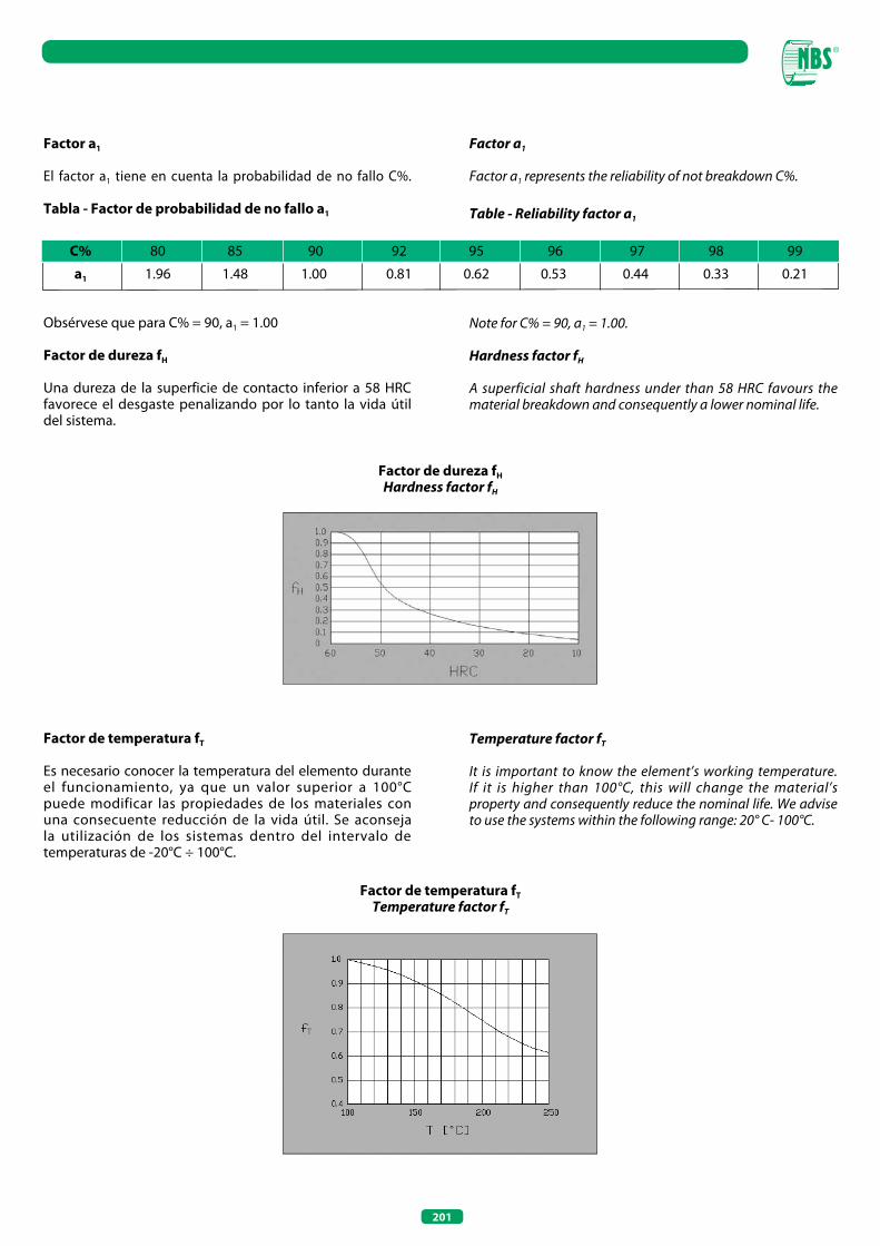
201
Factor a1
El factor a1 tiene en cuenta la probabilidad de no fallo C%.
Tabla - Factor de probabilidad de no fallo a1
Factor de dureza fH
Hardness factor fH
Factor de temperatura fT
Temperature factor fT
Obsérvese que para C% = 90, a1 = 1.00
Factor de dureza fH
Una dureza de la superficie de contacto inferior a 58 HRC favorece el desgaste penalizando por lo tanto la vida útil del sistema.
Factor de temperatura fT
Es necesario conocer la temperatura del elemento durante el funcionamiento, ya que un valor superior a 100°C puede modificar las propiedades de los materiales con una consecuente reducción de la vida útil. Se aconseja la utilización de los sistemas dentro del intervalo de temperaturas de -20°C ÷ 100°C.
Factor a1
Factor a1 represents the reliability of not breakdown C%.
Table - Reliability factor a1
Note for C% = 90, a1 = 1.00.
Hardness factor fH
A superficial shaft hardness under than 58 HRC favours the material breakdown and consequently a lower nominal life.
Temperature factor fT
It is important to know the element’s working temperature.If it is higher than 100°C, this will change the material’s property and consequently reduce the nominal life. We advise to use the systems within the following range: 20° C- 100°C.
C% 80 85 90 92 95 96 97 98 99
a1 1.96 1.48 1.00 0.81 0.62 0.53 0.44 0.33 0.21
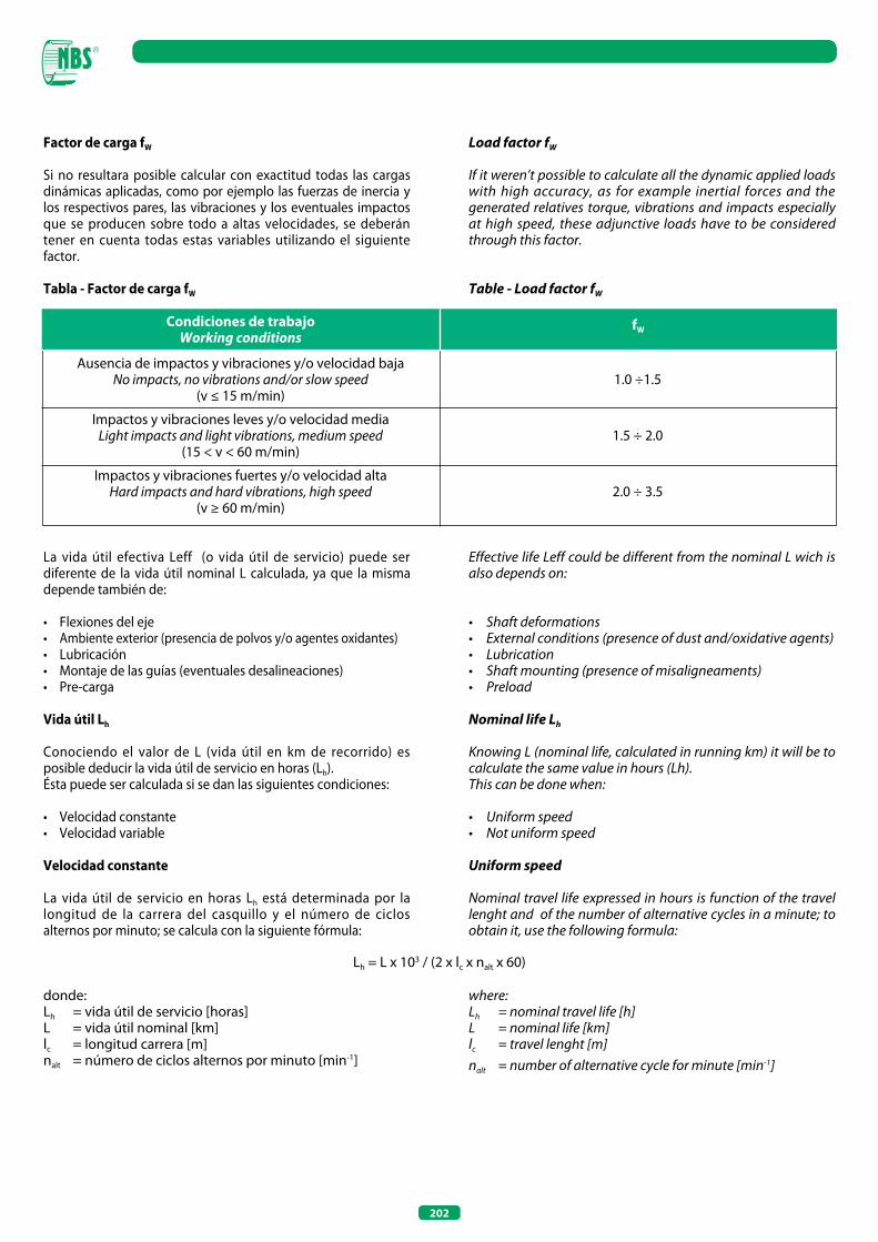
202
Factor de carga fW
Si no resultara posible calcular con exactitud todas las cargas dinámicas aplicadas, como por ejemplo las fuerzas de inercia y los respectivos pares, las vibraciones y los eventuales impactos que se producen sobre todo a altas velocidades, se deberán tener en cuenta todas estas variables utilizando el siguiente factor.
Tabla - Factor de carga fW
La vida útil efectiva Leff (o vida útil de servicio) puede ser diferente de la vida útil nominal L calculada, ya que la misma depende también de:
• Flexiones del eje• Ambiente exterior (presencia de polvos y/o agentes oxidantes)• Lubricación• Montaje de las guías (eventuales desalineaciones)• Pre-carga
Vida útil Lh
Conociendo el valor de L (vida útil en km de recorrido) es posible deducir la vida útil de servicio en horas (Lh).Ésta puede ser calculada si se dan las siguientes condiciones:
• Velocidad constante• Velocidad variable
Velocidad constante
La vida útil de servicio en horas Lh está determinada por la longitud de la carrera del casquillo y el número de ciclos alternos por minuto; se calcula con la siguiente fórmula:
donde:Lh = vida útil de servicio [horas]L = vida útil nominal [km]lc = longitud carrera [m]nalt = número de ciclos alternos por minuto [min-1]
Condiciones de trabajoWorking conditions
fW
Ausencia de impactos y vibraciones y/o velocidad bajaNo impacts, no vibrations and/or slow speed
(v ≤ 15 m/min)
Impactos y vibraciones leves y/o velocidad mediaLight impacts and light vibrations, medium speed
(15 < v < 60 m/min)
Impactos y vibraciones fuertes y/o velocidad altaHard impacts and hard vibrations, high speed
(v ≥ 60 m/min)
1.0 ÷1.5
1.5 ÷ 2.0
2.0 ÷ 3.5
Load factor fW
If it weren’t possible to calculate all the dynamic applied loads with high accuracy, as for example inertial forces and the generated relatives torque, vibrations and impacts especially at high speed, these adjunctive loads have to be considered through this factor.
Table - Load factor fW
Effective life Leff could be different from the nominal L wich is also depends on:
• Shaft deformations• External conditions (presence of dust and/oxidative agents)• Lubrication• Shaft mounting (presence of misaligneaments)• Preload
Nominal life Lh
Knowing L (nominal life, calculated in running km) it will be to calculate the same value in hours (Lh). This can be done when:
• Uniform speed• Not uniform speed
Uniform speed
Nominal travel life expressed in hours is function of the travel lenght and of the number of alternative cycles in a minute; to obtain it, use the following formula:
where:Lh = nominal travel life [h]L = nominal life [km]lc = travel lenght [m]nalt = number of alternative cycle for minute [min-1]
Lh = L x 103 / (2 x lc x nalt x 60)
203
Velocidad variable
La vida útil de servicio en horas Lh está supeditada a la velocidad media
donde:Lh = vida útil de servicio [horas]L = vida útil nominal [km]vm = velocidad media equivalente a: ∑ni=1 vi x qi [m/min]vi = velocidad porcentual [m/min]qi = distribución porcentual de vi (∑ni=1 qi = 1)
Resistencia de fricción
El cálculo de la resistencia de fricción C está dado por la siguiente fórmula:
donde:S = resistencia fricción (denominada también como fuerza de fricción o fuerza de empuje) [N]µ = coeficiente de fricción (0.002 ≤ µ ≤ 0.005 con P/C > 0,2)F = carga aplicada [N]f = fricción supeditada a: obturaciones, viscosidad del lubricante, precarga, etc (2 ≤ f ≤ 5 N por cada casquillo) [N]n° casquillos = número casquillos
Lubricación
Como todos los sistemas lineales comercializados, también los productos NBS necesitan una idónea lubricación para garantizar la vida útil prevista. En efecto, sin una adecuada lubricación, la fricción que se crearía favorecería el desgaste reduciendo la vida útil del sistema. Para la elección del tipo de lubricante tener en cuenta las siguientes consideraciones generales:
• para velocidades medidas y carrera horizontal: grasa a base de jabón de litio 2;• para velocidades elevadas: aceite de baja viscosidad;
La elección del tipo y la cantidad de lubricante está siempre supeditada a las condiciones de trabajo y a las características del lubricante mismo. Si el sistema trabaja en ambientes corrosivos se deberá prever una protección adicional.
AcoplamientoEn la siguiente tabla se exponen las tolerancias de acoplamiento eje-casquillo o eje-soporte:
S = µ x F + f x n° casquillos / bushes
Not uniform speed
Nominal travel life expressed in hours is function of the average speed
where:Lh = nominal travel life [h]L = nominal life [km]vm = average speed : ∑ni=1 vi x qi [m/min]vi = i-part speed [m/min]qi = i-part portion of vi (∑ni=1 qi = 1)
Friction resistance
The friction resistance S is given by the following relation:
where:S = friction resistance (named friction force or push force) [N]µ = friction coefficient (0.002 ≤ µ ≤ 0.005 with P/C > 0,2);F = load applied [N]f = friction function of: seals, lubricant, preload etc (2 ≤ f ≤ 5 N for each bush) [N]
n° bushes = number of bushes
Lubrication
As all linear systems, NBS linear system products need an adequate lubrication too as guarantee the calculated life; in fact, without the necessary lubrication there would be a significant reduction of nominal life caused by the wear and tear phenomenon. To choose the right lubricant use the following general indications:
• for median speed and horizontal travel: soap lithium greases 2;• for high speed: oil with low viscosity.
The optimal choice of lubricant and its quantity is always function of the work conditions and of its characteristics; if the external ambient is corrosive, use an adjunctive protection.
CouplingThe following table gives the fitting shaft-bush tolerances:
Lh = L x 103 / (vm x 60)
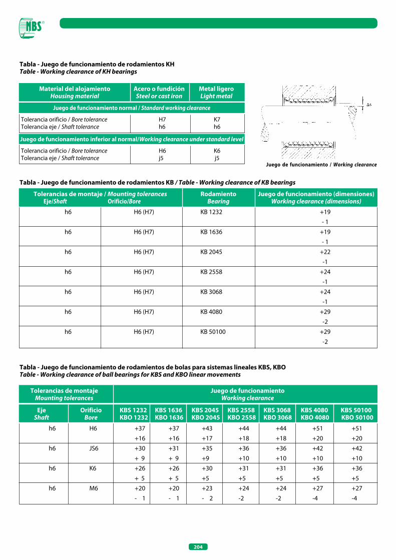
204
Tabla - Juego de funcionamiento de rodamientos KHTable - Working clearance of KH bearings
Tabla - Juego de funcionamiento de rodamientos KB / Table - Working clearance of KB bearings
Juego de funcionamiento / Working clearance
Material del alojamientoHousing material
Acero o fundiciónSteel or cast iron
Metal ligeroLight metal
Juego de funcionamiento normal / Standard working clearance
Juego de funcionamiento inferior al normal/Working clearance under standard level
Tolerancia orificio / Bore tolerance H7 K7Tolerancia eje / Shaft tolerance h6 h6
Tolerancia orificio / Bore tolerance H6 K6Tolerancia eje / Shaft tolerance j5 j5
RodamientoBearing
Juego de funcionamiento (dimensiones)Working clearance (dimensions)
h6 H6 (H7) KB 1232 +19 - 1 h6 H6 (H7) KB 1636 +19 - 1 h6 H6 (H7) KB 2045 +22 -1 h6 H6 (H7) KB 2558 +24 -1 h6 H6 (H7) KB 3068 +24 -1 h6 H6 (H7) KB 4080 +29 -2 h6 H6 (H7) KB 50100 +29 -2
Tolerancias de montaje / Mounting tolerances Eje/Shaft Orificio/Bore
Tabla - Juego de funcionamiento de rodamientos de bolas para sistemas lineales KBS, KBOTable - Working clearance of ball bearings for KBS and KBO linear movements
Tolerancias de montajeMounting tolerances
EjeShaft
OrificioBore
KBS 1232 KBS 1636 KBS 2045 KBS 2558 KBS 3068 KBS 4080 KBS 50100 KBO 1232 KBO 1636 KBO 2045 KBO 2558 KBO 3068 KBO 4080 KBO 50100
Juego de funcionamiento Working clearance
h6 H6 +37 +37 +43 +44 +44 +51 +51 +16 +16 +17 +18 +18 +20 +20 h6 JS6 +30 +31 +35 +36 +36 +42 +42 + 9 + 9 +9 +10 +10 +10 +10 h6 K6 +26 +26 +30 +31 +31 +36 +36 + 5 + 5 +5 +5 +5 +5 +5 h6 M6 +20 +20 +23 +24 +24 +27 +27 - 1 - 1 - 2 -2 -2 -4 -4
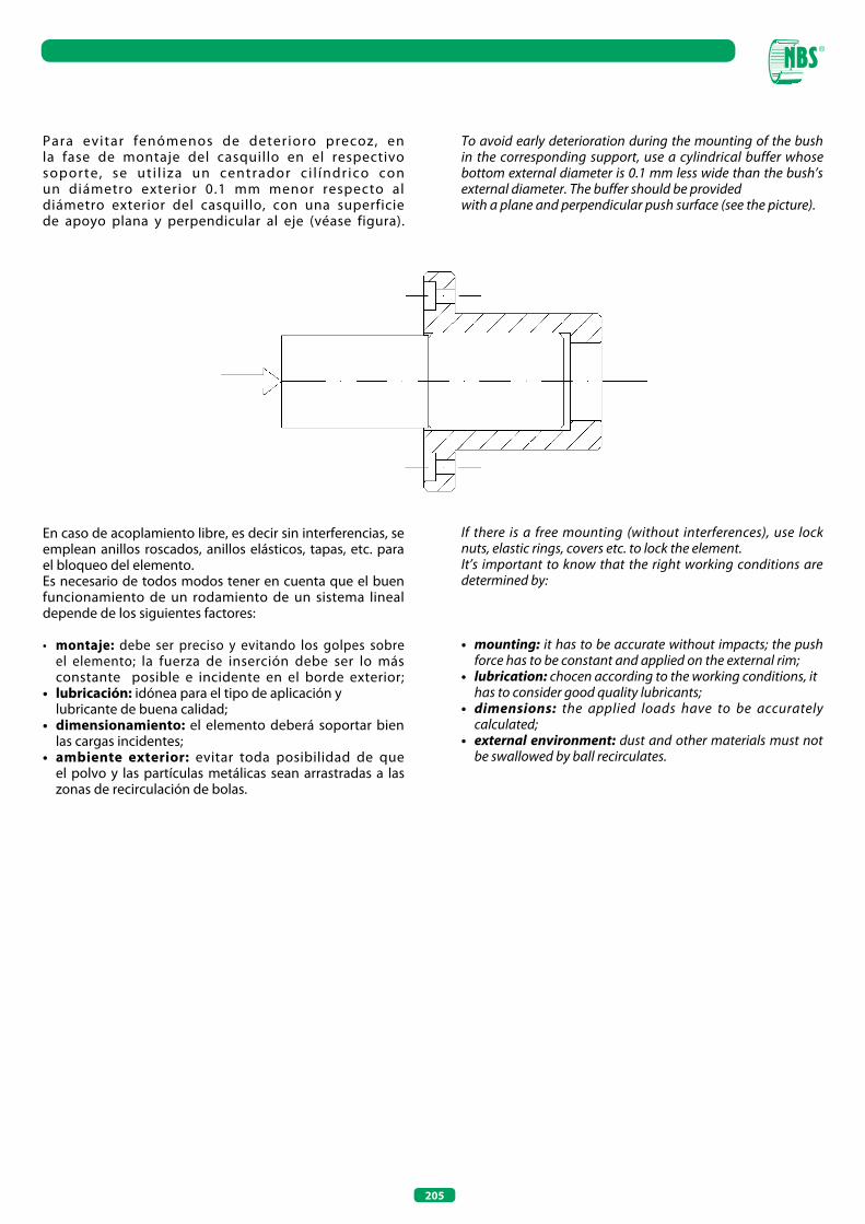
205
Para evitar fenómenos de deterioro precoz, en la fase de montaje del casquillo en el respectivo soporte, se ut i l iza un centrador c i l índrico con un diámetro exterior 0.1 mm menor respecto al diámetro exterior del casquillo, con una superficie de apoyo plana y perpendicular al eje (véase figura).
En caso de acoplamiento libre, es decir sin interferencias, se emplean anillos roscados, anillos elásticos, tapas, etc. para el bloqueo del elemento.Es necesario de todos modos tener en cuenta que el buen funcionamiento de un rodamiento de un sistema lineal depende de los siguientes factores:
• montaje: debe ser preciso y evitando los golpes sobre el elemento; la fuerza de inserción debe ser lo más constante posible e incidente en el borde exterior;• lubricación: idónea para el tipo de aplicación y lubricante de buena calidad;• dimensionamiento: el elemento deberá soportar bien las cargas incidentes;• ambiente exterior: evitar toda posibilidad de que el polvo y las partículas metálicas sean arrastradas a las zonas de recirculación de bolas.
To avoid early deterioration during the mounting of the bush in the corresponding support, use a cylindrical buffer whose bottom external diameter is 0.1 mm less wide than the bush’s external diameter. The buffer should be providedwith a plane and perpendicular push surface (see the picture).
If there is a free mounting (without interferences), use lock nuts, elastic rings, covers etc. to lock the element.It’s important to know that the right working conditions are determined by:
• mounting: it has to be accurate without impacts; the push force has to be constant and applied on the external rim;• lubrication: chocen according to the working conditions, it has to consider good quality lubricants;• dimensions: the applied loads have to be accurately calculated;• external environment: dust and other materials must not be swallowed by ball recirculates.
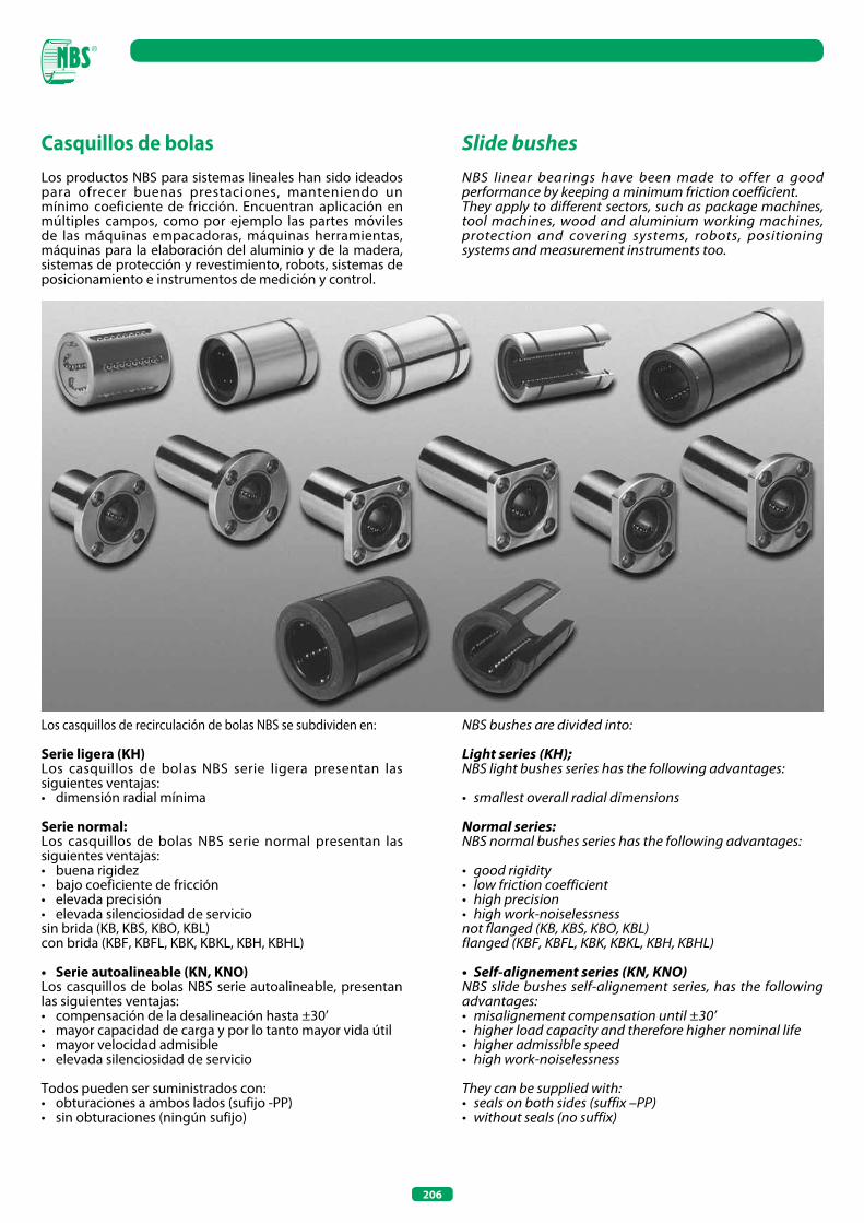
206
Casquillos de bolasLos productos NBS para sistemas lineales han sido ideados para ofrecer buenas prestaciones, manteniendo un mínimo coeficiente de fricción. Encuentran aplicación en múltiples campos, como por ejemplo las partes móviles de las máquinas empacadoras, máquinas herramientas, máquinas para la elaboración del aluminio y de la madera, sistemas de protección y revestimiento, robots, sistemas de posicionamiento e instrumentos de medición y control.
Los casquillos de recirculación de bolas NBS se subdividen en:
Serie ligera (KH)Los casquillos de bolas NBS serie ligera presentan las siguientes ventajas:• dimensión radial mínima
Serie normal:Los casquillos de bolas NBS serie normal presentan las siguientes ventajas:• buena rigidez• bajo coeficiente de fricción• elevada precisión• elevada silenciosidad de serviciosin brida (KB, KBS, KBO, KBL)con brida (KBF, KBFL, KBK, KBKL, KBH, KBHL)
• Serie autoalineable (KN, KNO)Los casquillos de bolas NBS serie autoalineable, presentan las siguientes ventajas:• compensación de la desalineación hasta ±30’• mayor capacidad de carga y por lo tanto mayor vida útil• mayor velocidad admisible• elevada silenciosidad de servicio
Todos pueden ser suministrados con:• obturaciones a ambos lados (sufijo -PP)• sin obturaciones (ningún sufijo)
Slide bushesNBS linear bearings have been made to offer a good performance by keeping a minimum friction coefficient.They apply to different sectors, such as package machines, tool machines, wood and aluminium working machines, protection and covering systems, robots, positioning systems and measurement instruments too.
NBS bushes are divided into:
Light series (KH);NBS light bushes series has the following advantages:
• smallest overall radial dimensions
Normal series:NBS normal bushes series has the following advantages:
• good rigidity• low friction coefficient• high precision• high work-noiselessnessnot flanged (KB, KBS, KBO, KBL)flanged (KBF, KBFL, KBK, KBKL, KBH, KBHL)
• Self-alignement series (KN, KNO)NBS slide bushes self-alignement series, has the following advantages:• misalignement compensation until ±30’• higher load capacity and therefore higher nominal life• higher admissible speed• high work-noiselessness
They can be supplied with:• seals on both sides (suffix –PP)• without seals (no suffix)
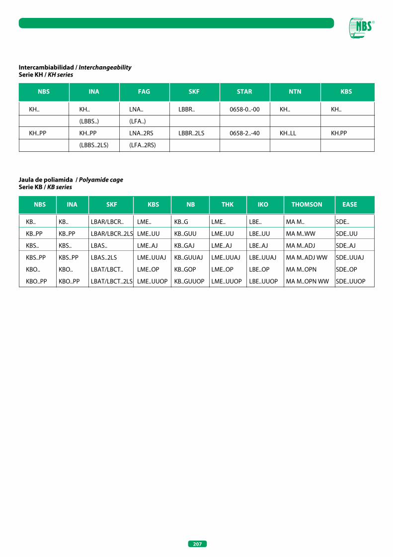
207
Intercambiabilidad / InterchangeabilitySerie KH / KH series
Jaula de poliamida / Polyamide cageSerie KB / KB series
NBS INA FAG SKF STAR NTN KBS
KH..
KH..PP
KH..
(LBBS..)
KH..PP
(LBBS..2LS)
LNA..
(LFA..)
LNA..2RS
(LFA..2RS)
LBBR..
LBBR..2LS
0658-0..-00
0658-2..-40
KH..
KH..LL
KH..
KH.PP
NBS INA SKF KBS NB THK IKO THOMSON EASE
KB..
KB..PP
KBS..
KBS..PP
KBO..
KBO..PP
KB..
KB..PP
KBS..
KBS..PP
KBO..
KBO..PP
LBAR/LBCR..
LBAR/LBCR..2LS
LBAS..
LBAS..2LS
LBAT/LBCT..
LBAT/LBCT..2LS
LME..
LME..UU
LME..AJ
LME..UUAJ
LME..OP
LME..UUOP
KB..G
KB..GUU
KB..GAJ
KB..GUUAJ
KB..GOP
KB..GUUOP
LME..
LME..UU
LME..AJ
LME..UUAJ
LME..OP
LME..UUOP
LBE..
LBE..UU
LBE..AJ
LBE..UUAJ
LBE..OP
LBE..UUOP
MA M..
MA M..WW
MA M..ADJ
MA M..ADJ WW
MA M..OPN
MA M..OPN WW
SDE..
SDE..UU
SDE..AJ
SDE..UUAJ
SDE..OP
SDE..UUOP
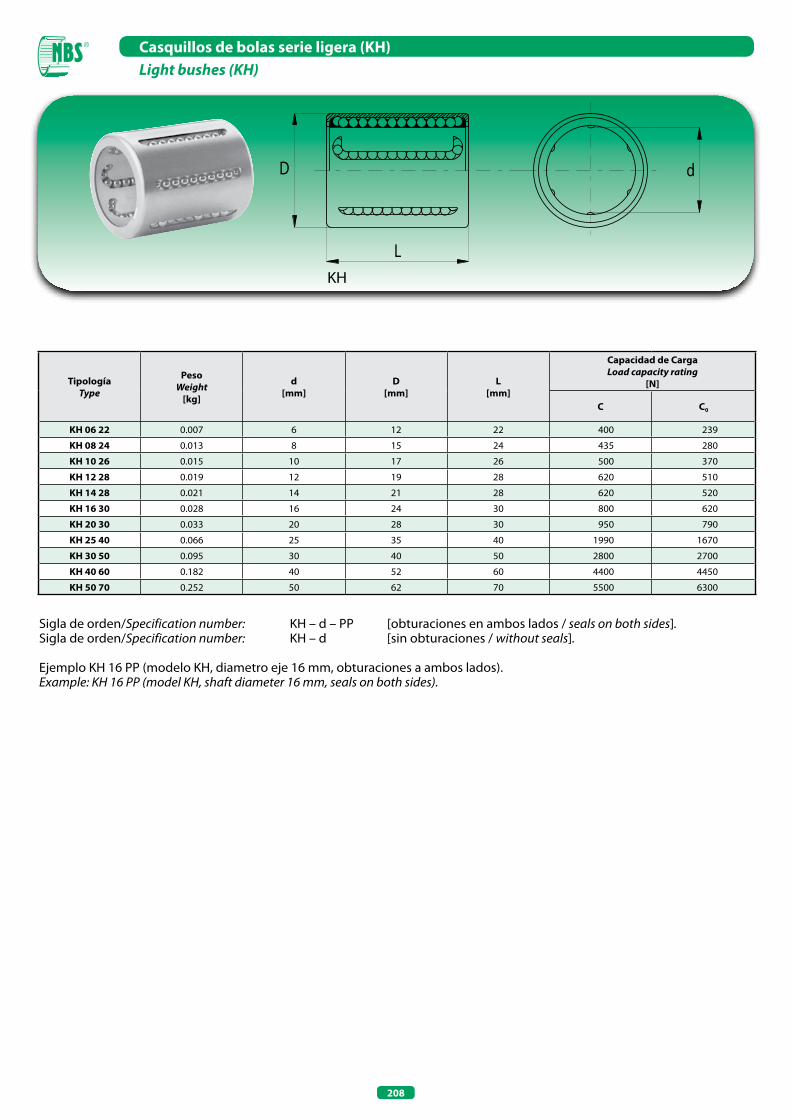
208
Casquillos de bolas serie ligera (KH)Light bushes (KH)
Sigla de orden/Specification number: KH – d – PP [obturaciones en ambos lados / seals on both sides].Sigla de orden/Specification number: KH – d [sin obturaciones / without seals].
Ejemplo KH 16 PP (modelo KH, diametro eje 16 mm, obturaciones a ambos lados).Example: KH 16 PP (model KH, shaft diameter 16 mm, seals on both sides).
TipologíaType
PesoWeight
[kg]
d[mm]
D [mm]
L [mm]
Capacidad de Carga Load capacity rating
[N]
C C0
KH 06 22 0.007 6 12 22 400 239
KH 08 24 0.013 8 15 24 435 280
KH 10 26 0.015 10 17 26 500 370
KH 12 28 0.019 12 19 28 620 510
KH 14 28 0.021 14 21 28 620 520
KH 16 30 0.028 16 24 30 800 620
KH 20 30 0.033 20 28 30 950 790
KH 25 40 0.066 25 35 40 1990 1670
KH 30 50 0.095 30 40 50 2800 2700
KH 40 60 0.182 40 52 60 4400 4450
KH 50 70 0.252 50 62 70 5500 6300
KH
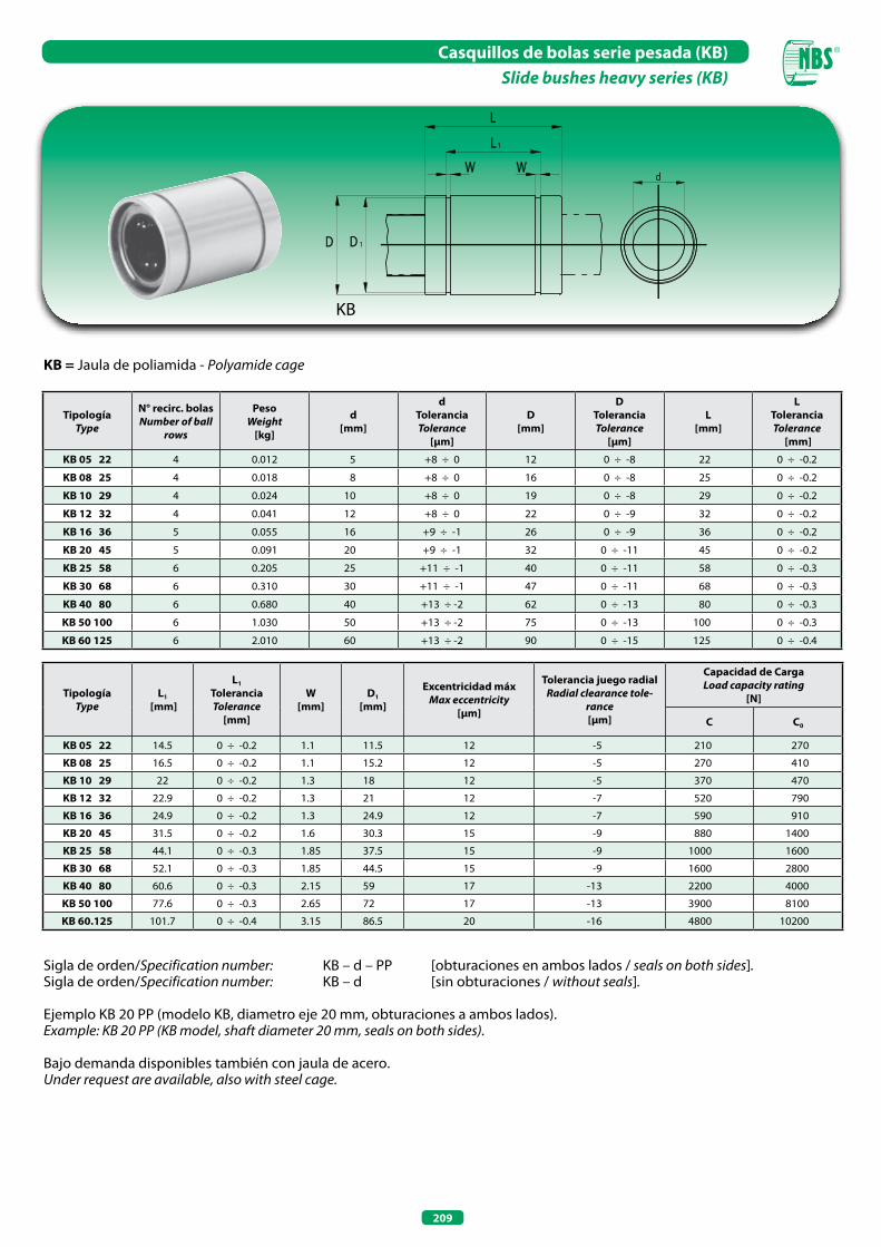
209
Casquillos de bolas serie pesada (KB)Slide bushes heavy series (KB)
Sigla de orden/Specification number: KB – d – PP [obturaciones en ambos lados / seals on both sides].Sigla de orden/Specification number: KB – d [sin obturaciones / without seals].
Ejemplo KB 20 PP (modelo KB, diametro eje 20 mm, obturaciones a ambos lados). Example: KB 20 PP (KB model, shaft diameter 20 mm, seals on both sides).
Bajo demanda disponibles también con jaula de acero.Under request are available, also with steel cage.
TipologíaType
N° recirc. bolasNumber of ball
rows
PesoWeight
[kg]
d[mm]
dToleranciaTolerance
[µm]
D[mm]
DToleranciaTolerance
[µm]
L[mm]
LToleranciaTolerance
[mm]
KB 05 22 4 0.012 5 +8 ÷ 0 12 0 ÷ -8 22 0 ÷ -0.2
KB 08 25 4 0.018 8 +8 ÷ 0 16 0 ÷ -8 25 0 ÷ -0.2
KB 10 29 4 0.024 10 +8 ÷ 0 19 0 ÷ -8 29 0 ÷ -0.2
KB 12 32 4 0.041 12 +8 ÷ 0 22 0 ÷ -9 32 0 ÷ -0.2
KB 16 36 5 0.055 16 +9 ÷ -1 26 0 ÷ -9 36 0 ÷ -0.2
KB 20 45 5 0.091 20 +9 ÷ -1 32 0 ÷ -11 45 0 ÷ -0.2
KB 25 58 6 0.205 25 +11 ÷ -1 40 0 ÷ -11 58 0 ÷ -0.3
KB 30 68 6 0.310 30 +11 ÷ -1 47 0 ÷ -11 68 0 ÷ -0.3
KB 40 80 6 0.680 40 +13 ÷ -2 62 0 ÷ -13 80 0 ÷ -0.3
KB 50 100 6 1.030 50 +13 ÷ -2 75 0 ÷ -13 100 0 ÷ -0.3
KB 60 125 6 2.010 60 +13 ÷ -2 90 0 ÷ -15 125 0 ÷ -0.4
TipologíaType
L1
[mm]
L1
ToleranciaTolerance
[mm]
W[mm]
D1
[mm]
Excentricidad máxMax eccentricity
[µm]
Tolerancia juego radialRadial clearance tole-
rance[µm]
Capacidad de Carga Load capacity rating
[N]
C C0
KB 05 22 14.5 0 ÷ -0.2 1.1 11.5 12 -5 210 270
KB 08 25 16.5 0 ÷ -0.2 1.1 15.2 12 -5 270 410
KB 10 29 22 0 ÷ -0.2 1.3 18 12 -5 370 470
KB 12 32 22.9 0 ÷ -0.2 1.3 21 12 -7 520 790
KB 16 36 24.9 0 ÷ -0.2 1.3 24.9 12 -7 590 910
KB 20 45 31.5 0 ÷ -0.2 1.6 30.3 15 -9 880 1400
KB 25 58 44.1 0 ÷ -0.3 1.85 37.5 15 -9 1000 1600
KB 30 68 52.1 0 ÷ -0.3 1.85 44.5 15 -9 1600 2800
KB 40 80 60.6 0 ÷ -0.3 2.15 59 17 -13 2200 4000
KB 50 100 77.6 0 ÷ -0.3 2.65 72 17 -13 3900 8100
KB 60.125 101.7 0 ÷ -0.4 3.15 86.5 20 -16 4800 10200
KB
KB = Jaula de poliamida - Polyamide cage
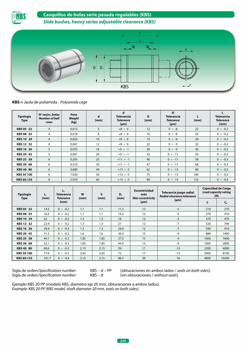
210
Casquillos de bolas serie pesada regulables (KBS)Slide bushes, heavy series adjustable clearance (KBS)
h
KBS = Jaula de poliamida - Polyamide cage
Sigla de orden/Specification number: KBS – d – PP [obturaciones en ambos lados / seals on both sides].Sigla de orden/Specification number: KBS – d [sin obturaciones / without seals].
Ejemplo KBS 20 PP (modelo KBS, diametro eje 20 mm, obturaciones a ambos lados).Example: KBS 20 PP (KBS model, shaft diameter 20 mm, seals on both sides).
TipologíaType
N° recirc. bolasNumber of ball
rows
PesoWeight
[kg]
d[mm]
dToleranciaTolerance
[µm]
D[mm]
DToleranciaTolerance
[µm]
L[mm]
LToleranciaTolerance
[mm]
KBS 05 22 4 0.012 5 +8 ÷ 0 12 0 ÷ -8 22 0 ÷ -0.2
KBS 08 25 4 0.018 8 +8 ÷ 0 16 0 ÷ -8 25 0 ÷ -0.2
KBS 10 29 4 0.024 10 +8 ÷ 0 19 0 ÷ -8 29 0 ÷ -0.2
KBS 12 32 4 0.041 12 +8 ÷ 0 22 0 ÷ -9 32 0 ÷ -0.2
KBS 16 36 5 0.055 16 +9 ÷ -1 26 0 ÷ -9 36 0 ÷ -0.2
KBS 20 45 5 0.091 20 +9 ÷ -1 32 0 ÷ -11 45 0 ÷ -0.2
KBS 25 58 6 0.205 25 +11 ÷ -1 40 0 ÷ -11 58 0 ÷ -0.3
KBS 30 68 6 0.310 30 +11 ÷ -1 47 0 ÷ -11 68 0 ÷ -0.3
KBS 40 80 6 0.680 40 +13 ÷ -2 62 0 ÷ -13 80 0 ÷ -0.3
KBS 50 100 6 1.030 50 +13 ÷ -2 75 0 ÷ -13 100 0 ÷ -0.3
KBS 60.125 6 2.010 60 +13 ÷ -2 90 0 ÷ -15 125 0 ÷ -0.4
TipologíaType
L1
[mm]
L1
ToleranciaTolerance
[mm]
W[mm]
h[mm]
D1
[mm]
Excentricidad máx
Max eccentricity [µm]
Tolerancia juego radialRadial clearance tolerance
[µm]
Capacidad de Carga Load capacity rating
[N]
C C0
KBS 05 22 14.5 0 ÷ -0.2 1.1 1.1 11.5 12 -5 210 270
KBS 08 25 16.5 0 ÷ -0.2 1.1 1.1 15.2 12 -5 270 410
KBS 10 29 22 0 ÷ -0.2 1.3 1.3 18 12 -5 370 470
KBS 12 32 22.9 0 ÷ -0.2 1.3 1.3 21 12 -7 520 790
KBS 16 36 24.9 0 ÷ -0.2 1.3 1.3 24.9 12 -7 590 910
KBS 20 45 31.5 0 ÷ -0.2 1.6 1.6 30.3 15 -9 880 1400
KBS 25 58 44.1 0 ÷ -0.3 1.85 1.85 37.5 15 -9 1000 1600
KBS 30 68 52.1 0 ÷ -0.3 1.85 1.85 44.5 15 -9 1600 2800
KBS 40 80 60.6 0 ÷ -0.3 2.15 2.15 59 17 -13 2200 4000
KBS 50 100 77.6 0 ÷ -0.3 2.65 2.65 72 17 -13 3900 8100
KBS 60.125 101.7 0 ÷ -0.4 3.15 3.15 86.5 20 -16 4800 10200
KBS
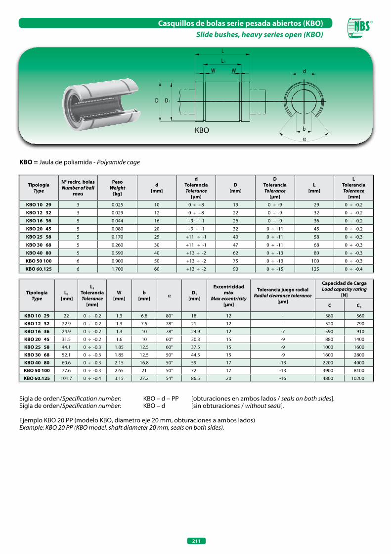
211
Casquillos de bolas serie pesada abiertos (KBO)Slide bushes, heavy series open (KBO)
α
KBO = Jaula de poliamida - Polyamide cage
Sigla de orden/Specification number: KBO – d – PP [obturaciones en ambos lados / seals on both sides].Sigla de orden/Specification number: KBO – d [sin obturaciones / without seals].
Ejemplo KBO 20 PP (modelo KBO, diametro eje 20 mm, obturaciones a ambos lados)Example: KBO 20 PP (KBO model, shaft diameter 20 mm, seals on both sides).
TipologíaType
N° recirc. bolasNumber of ball
rows
PesoWeight
[kg]
d[mm]
dToleranciaTolerance
[µm]
D[mm]
DToleranciaTolerance
[µm]
L[mm]
LToleranciaTolerance
[mm]
KBO 10 29 3 0.025 10 0 ÷ +8 19 0 ÷ -9 29 0 ÷ -0.2
KBO 12 32 3 0.029 12 0 ÷ +8 22 0 ÷ -9 32 0 ÷ -0.2
KBO 16 36 5 0.044 16 +9 ÷ -1 26 0 ÷ -9 36 0 ÷ -0.2
KBO 20 45 5 0.080 20 +9 ÷ -1 32 0 ÷ -11 45 0 ÷ -0.2
KBO 25 58 5 0.170 25 +11 ÷ -1 40 0 ÷ -11 58 0 ÷ -0.3
KBO 30 68 5 0.260 30 +11 ÷ -1 47 0 ÷ -11 68 0 ÷ -0.3
KBO 40 80 5 0.590 40 +13 ÷ -2 62 0 ÷ -13 80 0 ÷ -0.3
KBO 50 100 6 0.900 50 +13 ÷ -2 75 0 ÷ -13 100 0 ÷ -0.3
KBO 60.125 6 1.700 60 +13 ÷ -2 90 0 ÷ -15 125 0 ÷ -0.4
TipologíaType
L1
[mm]
L1
ToleranciaTolerance
[mm]
W[mm]
b [mm] a D1
[mm]
Excentricidad máx
Max eccentricity [µm]
Tolerancia juego radialRadial clearance tolerance
[µm]
Capacidad de Carga Load capacity rating
[N]
C C0
KBO 10 29 22 0 ÷ -0.2 1.3 6.8 80° 18 12 - 380 560
KBO 12 32 22.9 0 ÷ -0.2 1.3 7.5 78° 21 12 - 520 790
KBO 16 36 24.9 0 ÷ -0.2 1.3 10 78° 24.9 12 -7 590 910
KBO 20 45 31.5 0 ÷ -0.2 1.6 10 60° 30.3 15 -9 880 1400
KBO 25 58 44.1 0 ÷ -0.3 1.85 12.5 60° 37.5 15 -9 1000 1600
KBO 30 68 52.1 0 ÷ -0.3 1.85 12.5 50° 44.5 15 -9 1600 2800
KBO 40 80 60.6 0 ÷ -0.3 2.15 16.8 50° 59 17 -13 2200 4000
KBO 50 100 77.6 0 ÷ -0.3 2.65 21 50° 72 17 -13 3900 8100
KBO 60.125 101.7 0 ÷ -0.4 3.15 27.2 54° 86.5 20 -16 4800 10200
KBO
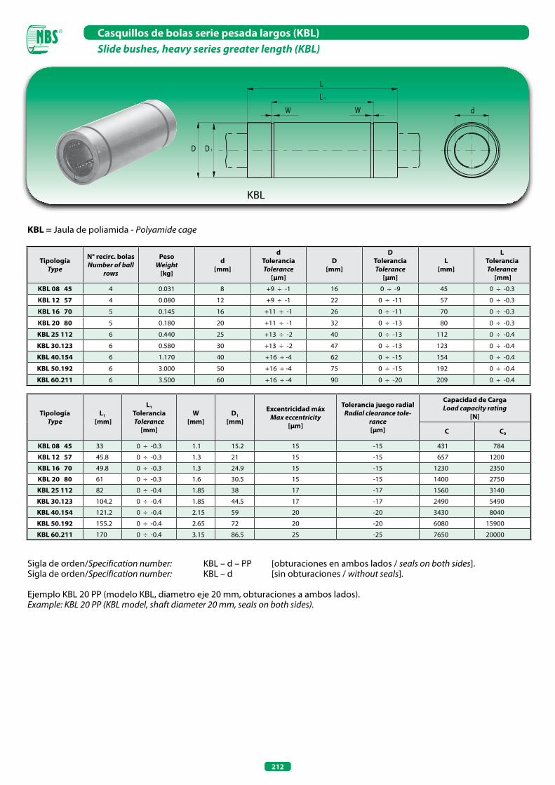
212
Casquillos de bolas serie pesada largos (KBL)Slide bushes, heavy series greater length (KBL)
KBL
KBL = Jaula de poliamida - Polyamide cage
Sigla de orden/Specification number: KBL – d – PP [obturaciones en ambos lados / seals on both sides].Sigla de orden/Specification number: KBL – d [sin obturaciones / without seals].
Ejemplo KBL 20 PP (modelo KBL, diametro eje 20 mm, obturaciones a ambos lados).Example: KBL 20 PP (KBL model, shaft diameter 20 mm, seals on both sides).
TipologíaType
N° recirc. bolasNumber of ball
rows
PesoWeight
[kg]
d[mm]
dToleranciaTolerance
[µm]
D[mm]
DToleranciaTolerance
[µm]
L[mm]
LToleranciaTolerance
[mm]
KBL 08 45 4 0.031 8 +9 ÷ -1 16 0 ÷ -9 45 0 ÷ -0.3
KBL 12 57 4 0.080 12 +9 ÷ -1 22 0 ÷ -11 57 0 ÷ -0.3
KBL 16 70 5 0.145 16 +11 ÷ -1 26 0 ÷ -11 70 0 ÷ -0.3
KBL 20 80 5 0.180 20 +11 ÷ -1 32 0 ÷ -13 80 0 ÷ -0.3
KBL 25 112 6 0.440 25 +13 ÷ -2 40 0 ÷ -13 112 0 ÷ -0.4
KBL 30.123 6 0.580 30 +13 ÷ -2 47 0 ÷ -13 123 0 ÷ -0.4
KBL 40.154 6 1.170 40 +16 ÷ -4 62 0 ÷ -15 154 0 ÷ -0.4
KBL 50.192 6 3.000 50 +16 ÷ -4 75 0 ÷ -15 192 0 ÷ -0.4
KBL 60.211 6 3.500 60 +16 ÷ -4 90 0 ÷ -20 209 0 ÷ -0.4
TipologíaType
L1
[mm]
L1
ToleranciaTolerance
[mm]
W[mm]
D1
[mm]
Excentricidad máxMax eccentricity
[µm]
Tolerancia juego radialRadial clearance tole-
rance[µm]
Capacidad de Carga Load capacity rating
[N]
C C0
KBL 08 45 33 0 ÷ -0.3 1.1 15.2 15 -15 431 784
KBL 12 57 45.8 0 ÷ -0.3 1.3 21 15 -15 657 1200
KBL 16 70 49.8 0 ÷ -0.3 1.3 24.9 15 -15 1230 2350
KBL 20 80 61 0 ÷ -0.3 1.6 30.5 15 -15 1400 2750
KBL 25 112 82 0 ÷ -0.4 1.85 38 17 -17 1560 3140
KBL 30.123 104.2 0 ÷ -0.4 1.85 44.5 17 -17 2490 5490
KBL 40.154 121.2 0 ÷ -0.4 2.15 59 20 -20 3430 8040
KBL 50.192 155.2 0 ÷ -0.4 2.65 72 20 -20 6080 15900
KBL 60.211 170 0 ÷ -0.4 3.15 86.5 25 -25 7650 20000
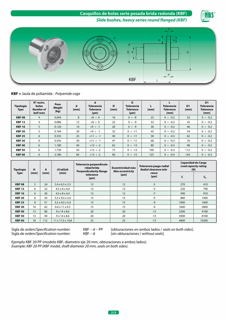
213
Casquillos de bolas serie pesada brida redonda (KBF)Slide bushes, heavy series round flanged (KBF)
KBF
KBF = Jaula de poliamida - Polyamide cage
Sigla de orden/Specification number: KBF – d – PP [obturaciones en ambos lados / seals on both sides].Sigla de orden/Specification number: KBF – d [sin obturaciones / without seals].
Ejemplo KBF 20 PP (modelo KBF, diametro eje 20 mm, obturaciones a ambos lados).Example: KBF 20 PP (KBF model, shaft diameter 20 mm, seals on both sides).
TipologíaType
N° recirc. bolas
Number of ball rows
PesoWeight
[kg]
d[mm]
dToleranciaTolerance
[µm]
D[mm]
DToleranciaTolerance
[µm]
L[mm]
LToleranciaTolerance
[mm]
D1 [mm]
D1ToleranciaTolerance
[mm]
KBF 08 4 0.044 8 +8 ÷ 0 16 0 ÷ -8 25 0 ÷ -0.2 32 0 ÷ -0.2
KBF 12 4 0.086 12 +8 ÷ 0 22 0 ÷ -9 32 0 ÷ -0.2 42 0 ÷ -0.2
KBF 16 5 0.120 16 +9 ÷ -1 26 0 ÷ -9 36 0 ÷ -0.2 46 0 ÷ -0.2
KBF 20 5 0.184 20 +9 ÷ -1 32 0 ÷ -11 45 0 ÷ -0.2 54 0 ÷ -0.2
KBF 25 6 0.335 25 +11 ÷ -1 40 0 ÷ -11 58 0 ÷ -0.3 62 0 ÷ -0.2
KBF 30 6 0.545 30 +11 ÷ -1 47 0 ÷ -11 68 0 ÷ -0.3 76 0 ÷ -0.2
KBF 40 6 1.180 40 +13 ÷ -2 62 0 ÷ -13 80 0 ÷ -0.3 98 0 ÷ -0.3
KBF 50 6 1.730 50 +13 ÷ -2 75 0 ÷ -13 100 0 ÷ -0.3 112 0 ÷ -0.3
KBF 60 6 3.180 60 +13 ÷ -2 90 0 ÷ -15 125 0 ÷ -0.4 134 0 ÷ -0.3
TipologíaType
H[mm]
A[mm]
d1xd2xh[mm]
Tolerancia perpendicula-ridad brida
Perpendicularity flange tolerance
[µm]
Excentricidad máxMax eccentricity
[µm]
Tolerancia juego radialRadial clearance tole-
rance[µm]
Capacidad de Carga Load capacity rating
[N]
C C0
KBF 08 5 24 3.4 x 6.5 x 3.3 12 12 -5 270 410
KBF 12 6 32 4,5 x 8 x 4,4 12 12 -5 520 790
KBF 16 6 36 4,5 x 8 x 4,4 12 12 -7 590 910
KBF 20 8 43 5,5 x 9,5 x 5,4 15 15 -9 880 1400
KBF 25 8 51 5,5 x 9,5 x 5,4 15 15 -9 1000 1600
KBF 30 10 62 6.6 x 11 x 6.5 15 15 -9 1600 2800
KBF 40 13 80 9 x 14 x 8,6 20 20 -13 2200 4100
KBF 50 13 94 9 x 14 x 8,6 20 20 -13 3900 8100
KBF 60 18 112 11 x 17,5 x 10,8 25 25 -13 4800 10200
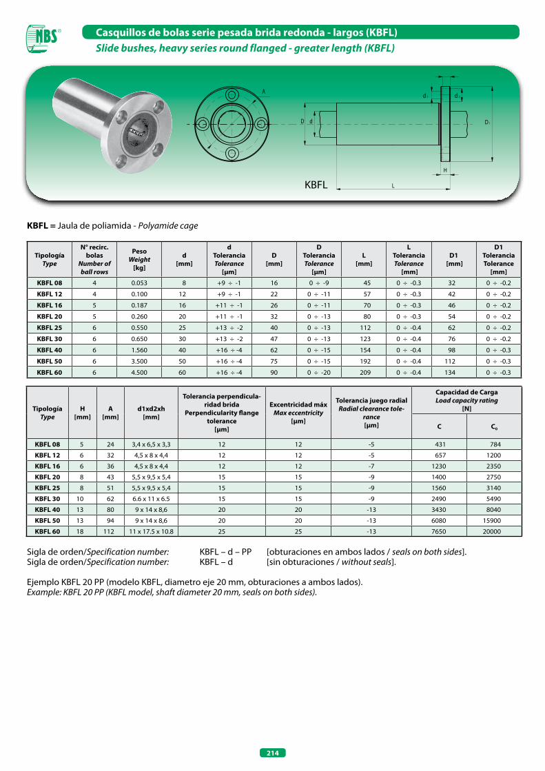
214
Casquillos de bolas serie pesada brida redonda - largos (KBFL)Slide bushes, heavy series round flanged - greater length (KBFL)
KBFL = Jaula de poliamida - Polyamide cage
Sigla de orden/Specification number: KBFL – d – PP [obturaciones en ambos lados / seals on both sides].Sigla de orden/Specification number: KBFL – d [sin obturaciones / without seals].
Ejemplo KBFL 20 PP (modelo KBFL, diametro eje 20 mm, obturaciones a ambos lados).Example: KBFL 20 PP (KBFL model, shaft diameter 20 mm, seals on both sides).
TipologíaType
N° recirc. bolas
Number of ball rows
PesoWeight
[kg]
d[mm]
dToleranciaTolerance
[µm]
D[mm]
DToleranciaTolerance
[µm]
L[mm]
LToleranciaTolerance
[mm]
D1 [mm]
D1ToleranciaTolerance
[mm]
KBFL 08 4 0.053 8 +9 ÷ -1 16 0 ÷ -9 45 0 ÷ -0.3 32 0 ÷ -0.2
KBFL 12 4 0.100 12 +9 ÷ -1 22 0 ÷ -11 57 0 ÷ -0.3 42 0 ÷ -0.2
KBFL 16 5 0.187 16 +11 ÷ -1 26 0 ÷ -11 70 0 ÷ -0.3 46 0 ÷ -0.2
KBFL 20 5 0.260 20 +11 ÷ -1 32 0 ÷ -13 80 0 ÷ -0.3 54 0 ÷ -0.2
KBFL 25 6 0.550 25 +13 ÷ -2 40 0 ÷ -13 112 0 ÷ -0.4 62 0 ÷ -0.2
KBFL 30 6 0.650 30 +13 ÷ -2 47 0 ÷ -13 123 0 ÷ -0.4 76 0 ÷ -0.2
KBFL 40 6 1.560 40 +16 ÷ -4 62 0 ÷ -15 154 0 ÷ -0.4 98 0 ÷ -0.3
KBFL 50 6 3.500 50 +16 ÷ -4 75 0 ÷ -15 192 0 ÷ -0.4 112 0 ÷ -0.3
KBFL 60 6 4.500 60 +16 ÷ -4 90 0 ÷ -20 209 0 ÷ -0.4 134 0 ÷ -0.3
TipologíaType
H[mm]
A[mm]
d1xd2xh[mm]
Tolerancia perpendicula-ridad brida
Perpendicularity flange tolerance
[µm]
Excentricidad máxMax eccentricity
[µm]
Tolerancia juego radialRadial clearance tole-
rance[µm]
Capacidad de Carga Load capacity rating
[N]
C C0
KBFL 08 5 24 3,4 x 6,5 x 3,3 12 12 -5 431 784
KBFL 12 6 32 4,5 x 8 x 4,4 12 12 -5 657 1200
KBFL 16 6 36 4,5 x 8 x 4,4 12 12 -7 1230 2350
KBFL 20 8 43 5,5 x 9,5 x 5,4 15 15 -9 1400 2750
KBFL 25 8 51 5,5 x 9,5 x 5,4 15 15 -9 1560 3140
KBFL 30 10 62 6.6 x 11 x 6.5 15 15 -9 2490 5490
KBFL 40 13 80 9 x 14 x 8,6 20 20 -13 3430 8040
KBFL 50 13 94 9 x 14 x 8,6 20 20 -13 6080 15900
KBFL 60 18 112 11 x 17.5 x 10.8 25 25 -13 7650 20000
KBFL
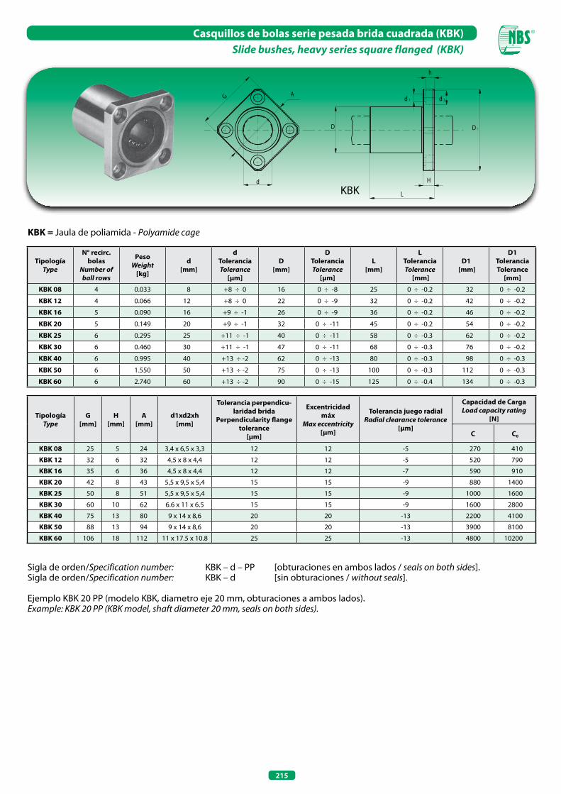
215
Casquillos de bolas serie pesada brida cuadrada (KBK)Slide bushes, heavy series square flanged (KBK)
KBK = Jaula de poliamida - Polyamide cage
Sigla de orden/Specification number: KBK – d – PP [obturaciones en ambos lados / seals on both sides].Sigla de orden/Specification number: KBK – d [sin obturaciones / without seals].
Ejemplo KBK 20 PP (modelo KBK, diametro eje 20 mm, obturaciones a ambos lados).Example: KBK 20 PP (KBK model, shaft diameter 20 mm, seals on both sides).
TipologíaType
N° recirc. bolas
Number of ball rows
PesoWeight
[kg]
d[mm]
dToleranciaTolerance
[µm]
D[mm]
DToleranciaTolerance
[µm]
L[mm]
LToleranciaTolerance
[mm]
D1 [mm]
D1ToleranciaTolerance
[mm]
KBK 08 4 0.033 8 +8 ÷ 0 16 0 ÷ -8 25 0 ÷ -0.2 32 0 ÷ -0.2
KBK 12 4 0.066 12 +8 ÷ 0 22 0 ÷ -9 32 0 ÷ -0.2 42 0 ÷ -0.2
KBK 16 5 0.090 16 +9 ÷ -1 26 0 ÷ -9 36 0 ÷ -0.2 46 0 ÷ -0.2
KBK 20 5 0.149 20 +9 ÷ -1 32 0 ÷ -11 45 0 ÷ -0.2 54 0 ÷ -0.2
KBK 25 6 0.295 25 +11 ÷ -1 40 0 ÷ -11 58 0 ÷ -0.3 62 0 ÷ -0.2
KBK 30 6 0.460 30 +11 ÷ -1 47 0 ÷ -11 68 0 ÷ -0.3 76 0 ÷ -0.2
KBK 40 6 0.995 40 +13 ÷ -2 62 0 ÷ -13 80 0 ÷ -0.3 98 0 ÷ -0.3
KBK 50 6 1.550 50 +13 ÷ -2 75 0 ÷ -13 100 0 ÷ -0.3 112 0 ÷ -0.3
KBK 60 6 2.740 60 +13 ÷ -2 90 0 ÷ -15 125 0 ÷ -0.4 134 0 ÷ -0.3
TipologíaType
G[mm]
H[mm]
A[mm]
d1xd2xh[mm]
Tolerancia perpendicu-laridad brida
Perpendicularity flange tolerance
[µm]
Excentricidad máx
Max eccentricity [µm]
Tolerancia juego radialRadial clearance tolerance
[µm]
Capacidad de Carga Load capacity rating
[N]
C C0
KBK 08 25 5 24 3,4 x 6,5 x 3,3 12 12 -5 270 410
KBK 12 32 6 32 4,5 x 8 x 4,4 12 12 -5 520 790
KBK 16 35 6 36 4,5 x 8 x 4,4 12 12 -7 590 910
KBK 20 42 8 43 5,5 x 9,5 x 5,4 15 15 -9 880 1400
KBK 25 50 8 51 5,5 x 9,5 x 5,4 15 15 -9 1000 1600
KBK 30 60 10 62 6.6 x 11 x 6.5 15 15 -9 1600 2800
KBK 40 75 13 80 9 x 14 x 8,6 20 20 -13 2200 4100
KBK 50 88 13 94 9 x 14 x 8,6 20 20 -13 3900 8100
KBK 60 106 18 112 11 x 17.5 x 10.8 25 25 -13 4800 10200
KBK
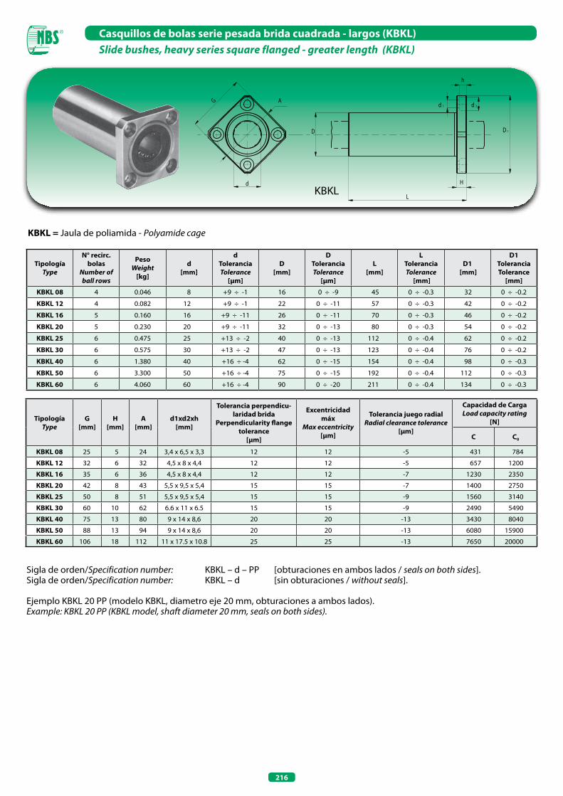
216
Casquillos de bolas serie pesada brida cuadrada - largos (KBKL)Slide bushes, heavy series square flanged - greater length (KBKL)
KBKL
KBKL = Jaula de poliamida - Polyamide cage
Sigla de orden/Specification number: KBKL – d – PP [obturaciones en ambos lados / seals on both sides].Sigla de orden/Specification number: KBKL – d [sin obturaciones / without seals].
Ejemplo KBKL 20 PP (modelo KBKL, diametro eje 20 mm, obturaciones a ambos lados).Example: KBKL 20 PP (KBKL model, shaft diameter 20 mm, seals on both sides).
TipologíaType
N° recirc. bolas
Number of ball rows
PesoWeight
[kg]
d[mm]
dToleranciaTolerance
[µm]
D[mm]
DToleranciaTolerance
[µm]
L[mm]
LToleranciaTolerance
[mm]
D1 [mm]
D1ToleranciaTolerance
[mm]
KBKL 08 4 0.046 8 +9 ÷ -1 16 0 ÷ -9 45 0 ÷ -0.3 32 0 ÷ -0.2
KBKL 12 4 0.082 12 +9 ÷ -1 22 0 ÷ -11 57 0 ÷ -0.3 42 0 ÷ -0.2
KBKL 16 5 0.160 16 +9 ÷ -11 26 0 ÷ -11 70 0 ÷ -0.3 46 0 ÷ -0.2
KBKL 20 5 0.230 20 +9 ÷ -11 32 0 ÷ -13 80 0 ÷ -0.3 54 0 ÷ -0.2
KBKL 25 6 0.475 25 +13 ÷ -2 40 0 ÷ -13 112 0 ÷ -0.4 62 0 ÷ -0.2
KBKL 30 6 0.575 30 +13 ÷ -2 47 0 ÷ -13 123 0 ÷ -0.4 76 0 ÷ -0.2
KBKL 40 6 1.380 40 +16 ÷ -4 62 0 ÷ -15 154 0 ÷ -0.4 98 0 ÷ -0.3
KBKL 50 6 3.300 50 +16 ÷ -4 75 0 ÷ -15 192 0 ÷ -0.4 112 0 ÷ -0.3
KBKL 60 6 4.060 60 +16 ÷ -4 90 0 ÷ -20 211 0 ÷ -0.4 134 0 ÷ -0.3
TipologíaType
G[mm]
H[mm]
A[mm]
d1xd2xh[mm]
Tolerancia perpendicu-laridad brida
Perpendicularity flange tolerance
[µm]
Excentricidad máx
Max eccentricity [µm]
Tolerancia juego radialRadial clearance tolerance
[µm]
Capacidad de Carga Load capacity rating
[N]
C C0
KBKL 08 25 5 24 3,4 x 6,5 x 3,3 12 12 -5 431 784
KBKL 12 32 6 32 4,5 x 8 x 4,4 12 12 -5 657 1200
KBKL 16 35 6 36 4,5 x 8 x 4,4 12 12 -7 1230 2350
KBKL 20 42 8 43 5,5 x 9,5 x 5,4 15 15 -7 1400 2750
KBKL 25 50 8 51 5,5 x 9,5 x 5,4 15 15 -9 1560 3140
KBKL 30 60 10 62 6.6 x 11 x 6.5 15 15 -9 2490 5490
KBKL 40 75 13 80 9 x 14 x 8,6 20 20 -13 3430 8040
KBKL 50 88 13 94 9 x 14 x 8,6 20 20 -13 6080 15900
KBKL 60 106 18 112 11 x 17.5 x 10.8 25 25 -13 7650 20000

217
Casquillos de bolas serie pesada brida redonda cortada (KBH)Slide bushes, heavy series round cutted flange (KBH)
KBH
KBH = Jaula de poliamida - Polyamide cage
Sigla de orden/Specification number: KBH – d – PP [obturaciones en ambos lados / seals on both sides].Sigla de orden/Specification number: KBH – d [sin obturaciones / without seals].
Ejemplo KBH 20 PP (modelo KBH, diametro eje 20 mm, obturaciones a ambos lados).Example: KBH 20 PP (KBH model, shaft diameter 20 mm, seals on both sides).
TipologíaType
N° recirc. bolas
Number of ball rows
PesoWeight
[kg]
d[mm]
dToleranciaTolerance
[µm]
D[mm]
DToleranciaTolerance
[µm]
L[mm]
LToleranciaTolerance
[mm]
D1 [mm]
D1ToleranciaTolerance
[mm]
KBH 06 4 0.021 6 0 ÷ -9 12 0 ÷ -11 19 0 ÷ -0.2 28 0 ÷ -0.2
KBH 08 4 0.033 8 0 ÷ -9 15 0 ÷ -11 24 0 ÷ -0.2 32 0 ÷ -0.2
KBH 10 4 0.064 10 0 ÷ -9 19 0 ÷ -13 29 0 ÷ -0.2 40 0 ÷ -0.2
KBH 12 4 0.068 12 0 ÷ -9 21 0 ÷ -13 30 0 ÷ -0.2 42 0 ÷ -0.2
KBH 13 4 0.081 13 0 ÷ -9 23 0 ÷ -13 32 0 ÷ -0.2 43 0 ÷ -0.2
KBH 16 5 0.112 16 0 ÷ -9 28 0 ÷ -13 37 0 ÷ -0.2 48 0 ÷ -0.2
KBH 20 5 0.167 20 0 ÷ -10 32 0 ÷ -16 42 0 ÷ -0.2 54 0 ÷ -0.2
KBH 25 6 0.325 25 0 ÷ -10 40 0 ÷ -16 59 0 ÷ -0.3 62 0 ÷ -0.2
KBH 30 6 0.388 30 0 ÷ -10 45 0 ÷ -16 64 0 ÷ -0.3 74 0 ÷ -0.2
TipologíaType
W[mm]
H[mm]
A[mm]
F[mm]
d1xd2xh[mm]
Tolerancia perpendicu-laridad brida
Perpendicularity flange tolerance
[µm]
Excentricidad máx
Max eccentricity [µm]
Tolerancia juego radialRadial clearance tolerance
[µm]
Capacidad de Carga Load capacity rating
[N]
C C0
KBH 06 18 5 20 - 3,4 x 6,5 x 3,3 12 12 -5 210 270
KBH 08 21 5 24 - 3,4 x 6,5 x 3,3 12 12 -5 270 410
KBH 10 25 6 29 - 4,5 x 8 x 4,4 12 12 -5 380 560
KBH 12 27 6 32 - 4,5 x 8 x 4,4 12 12 -5 420 610
KBH 13 29 6 33 - 4,5 x 8 x 4,4 12 12 -7 520 790
KBH 16 34 6 31 22 4,5 x 8 x 4,4 12 12 -7 790 1200
KBH 20 38 8 36 24 5,5 x 9,5 x 5,4 15 15 -9 880 1400
KBH 25 46 8 40 32 5,5 x 9,5 x 5,4 15 15 -9 1000 1600
KBH 30 51 10 49 35 6.6 x 11 x 6.5 15 15 -9 1600 2800
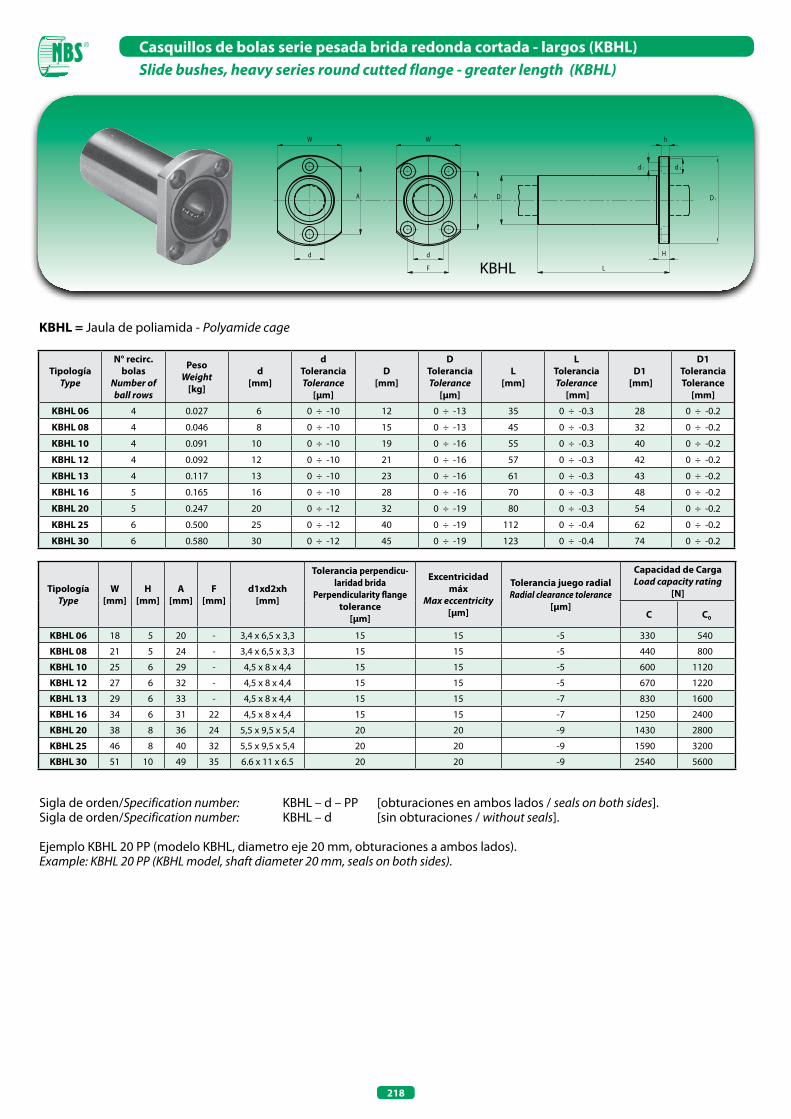
218
Casquillos de bolas serie pesada brida redonda cortada - largos (KBHL)Slide bushes, heavy series round cutted flange - greater length (KBHL)
KBHL = Jaula de poliamida - Polyamide cage
Sigla de orden/Specification number: KBHL – d – PP [obturaciones en ambos lados / seals on both sides].Sigla de orden/Specification number: KBHL – d [sin obturaciones / without seals].
Ejemplo KBHL 20 PP (modelo KBHL, diametro eje 20 mm, obturaciones a ambos lados).Example: KBHL 20 PP (KBHL model, shaft diameter 20 mm, seals on both sides).
TipologíaType
N° recirc. bolas
Number of ball rows
PesoWeight
[kg]
d[mm]
dToleranciaTolerance
[µm]
D[mm]
DToleranciaTolerance
[µm]
L[mm]
LToleranciaTolerance
[mm]
D1 [mm]
D1ToleranciaTolerance
[mm]
KBHL 06 4 0.027 6 0 ÷ -10 12 0 ÷ -13 35 0 ÷ -0.3 28 0 ÷ -0.2
KBHL 08 4 0.046 8 0 ÷ -10 15 0 ÷ -13 45 0 ÷ -0.3 32 0 ÷ -0.2
KBHL 10 4 0.091 10 0 ÷ -10 19 0 ÷ -16 55 0 ÷ -0.3 40 0 ÷ -0.2
KBHL 12 4 0.092 12 0 ÷ -10 21 0 ÷ -16 57 0 ÷ -0.3 42 0 ÷ -0.2
KBHL 13 4 0.117 13 0 ÷ -10 23 0 ÷ -16 61 0 ÷ -0.3 43 0 ÷ -0.2
KBHL 16 5 0.165 16 0 ÷ -10 28 0 ÷ -16 70 0 ÷ -0.3 48 0 ÷ -0.2
KBHL 20 5 0.247 20 0 ÷ -12 32 0 ÷ -19 80 0 ÷ -0.3 54 0 ÷ -0.2
KBHL 25 6 0.500 25 0 ÷ -12 40 0 ÷ -19 112 0 ÷ -0.4 62 0 ÷ -0.2
KBHL 30 6 0.580 30 0 ÷ -12 45 0 ÷ -19 123 0 ÷ -0.4 74 0 ÷ -0.2
TipologíaType
W[mm]
H[mm]
A[mm]
F[mm]
d1xd2xh[mm]
Tolerancia perpendicu-laridad brida
Perpendicularity flange tolerance
[µm]
Excentricidad máx
Max eccentricity [µm]
Tolerancia juego radialRadial clearance tolerance
[µm]
Capacidad de Carga Load capacity rating
[N]
C C0
KBHL 06 18 5 20 - 3,4 x 6,5 x 3,3 15 15 -5 330 540
KBHL 08 21 5 24 - 3,4 x 6,5 x 3,3 15 15 -5 440 800
KBHL 10 25 6 29 - 4,5 x 8 x 4,4 15 15 -5 600 1120
KBHL 12 27 6 32 - 4,5 x 8 x 4,4 15 15 -5 670 1220
KBHL 13 29 6 33 - 4,5 x 8 x 4,4 15 15 -7 830 1600
KBHL 16 34 6 31 22 4,5 x 8 x 4,4 15 15 -7 1250 2400
KBHL 20 38 8 36 24 5,5 x 9,5 x 5,4 20 20 -9 1430 2800
KBHL 25 46 8 40 32 5,5 x 9,5 x 5,4 20 20 -9 1590 3200
KBHL 30 51 10 49 35 6.6 x 11 x 6.5 20 20 -9 2540 5600
KBHL

219
Casquillos de bolas autoalineables (KN)Self-aligning slide bushes (KN)
Sigla de orden/Specification number: KN – d – PP [obturaciones en ambos lados / seals on both sides].Sigla de orden/Specification number: KN – d [sin obturaciones / without seals].
Ejemplo KN 20 PP (modelo KN, diametro eje 20 mm, obturaciones a ambos lados).Example: KN 20 PP (KN model, shaft diameter 20 mm, seals on both sides).
TipologíaType
N° recirc. bolas
Number of ball rows
PesoWeight
[kg]
DimensionesDimensions
Juego radialRadial clearance
Capacidad de Carga Load capacity rating
[N]
d[mm]
D[mm]
B[mm]
B1 [mm]
h7/H7[µm]
h7/JS7[µm]
h6/JS6[µm] C C0
KN 12 32 5 0.023 12 22 32 20 + 32+ 3
+ 28- 1
+ 220 650 520
KN 16 36 5 0.028 16 26 36 22 + 32+ 3
+ 28- 1
+ 220 800 630
KN 20 45 6 0.061 20 32 45 28 + 37+ 4
+ 30- 2
+ 240 1500 1250
KN 25 58 6 0.122 25 40 58 40 + 37+ 5
+ 31- 2
+ 240 2500 2200
KN 30 68 6 0.185 30 47 68 48 + 39+ 3
+ 33- 3
+ 270 3200 2800
KN 40 80 6 0.360 40 62 80 56 + 42+ 1
+ 34- 6
+ 27- 4 5500 4900
KN 50 100 6 0.580 50 75 100 72 + 310
+ 26- 7
+ 26- 4 8600 7100
KN
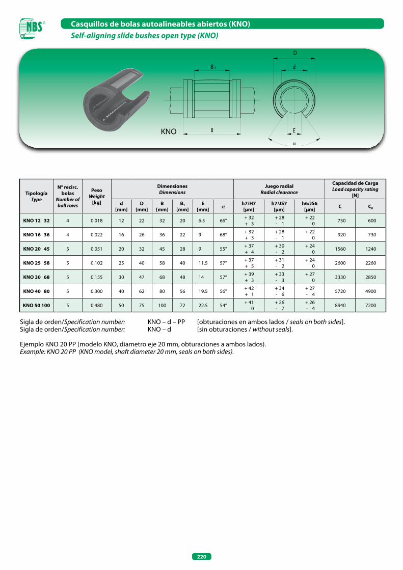
220
Casquillos de bolas autoalineables abiertos (KNO)Self-aligning slide bushes open type (KNo)
α
Sigla de orden/Specification number: KNO – d – PP [obturaciones en ambos lados / seals on both sides].Sigla de orden/Specification number: KNO – d [sin obturaciones / without seals].
Ejemplo KNO 20 PP (modelo KNO, diametro eje 20 mm, obturaciones a ambos lados).Example: KNO 20 PP (KNO model, shaft diameter 20 mm, seals on both sides).
TipologíaType
N° recirc. bolas
Number of ball rows
PesoWeight
[kg]
DimensionesDimensions
Juego radialRadial clearance
Capacidad de Carga Load capacity rating
[N]
d[mm]
D[mm]
B[mm]
B1 [mm]
E[mm] a h7/H7
[µm]h7/JS7
[µm]h6/JS6
[µm] C C0
KNO 12 32 4 0.018 12 22 32 20 6.5 66° + 32+ 3
+ 28- 1
+ 220 750 600
KNO 16 36 4 0.022 16 26 36 22 9 68° + 32+ 3
+ 28- 1
+ 220 920 730
KNO 20 45 5 0.051 20 32 45 28 9 55° + 37+ 4
+ 30- 2
+ 240 1560 1240
KNO 25 58 5 0.102 25 40 58 40 11.5 57° + 37+ 5
+ 31- 2
+ 240 2600 2260
KNO 30 68 5 0.155 30 47 68 48 14 57° + 39+ 3
+ 33- 3
+ 270 3330 2850
KNO 40 80 5 0.300 40 62 80 56 19.5 56° + 42+ 1
+ 34- 6
+ 27- 4 5720 4900
KNO 50 100 5 0.480 50 75 100 72 22.5 54° + 410
+ 26- 7
+ 26- 4 8940 7200
KNO

221
Soportes terminales para ejes (SK)End shaft supports (SK)
0,
02
Sigla de orden: SK – dSpecification number: SK – d
TipologíaType
PesoWeight
[kg]
d[mm]
h [mm]
W [mm]
B[mm]
P[mm]
S[mm]
G[mm]
H[mm]
L [mm]
Tornillos de montaje
Mounting bolt
SK 08 0.024 8 20 42 32 18 5.5 6 32.8 14 M 5
SK 10 0.024 10 20 42 32 18 5.5 6 32.8 14 M 5
SK 12 0.030 12 23 42 32 20 5.5 6 37.5 14 M 5
SK 13 0.030 13 23 42 32 20 5.5 6 37.5 14 M 5
SK 16 0.040 16 27 48 38 25 5.5 8 44 16 M 5
SK 20 0.070 20 31 60 45 30 6.6 10 51 20 M 6
SK 25 0.130 25 35 70 56 38 6.6 12 60 24 M 6
SK 30 0.180 30 42 84 64 44 9 12 70 28 M 8
SK 35 0.270 35 50 98 74 50 11 15 85 32 M 10
SK 40 0.420 40 60 114 90 60 11 15 96 36 M 10
SK 50 0.750 50 70 126 100 74 14 18 120 40 M 12
SK 60 1.100 60 80 148 120 90 14 18 136 45 M 12
SK

222
Soportes de aleación de aluminio
Los soportes NBS se subdividen en:
Serie normal:
• estándar (SC)• cortos (SCV)• largos (SCW)
Serie abierta:
• sin brida (SBR)• con brida (TBR)
Todos pueden ser suministrados con:
• obturaciones a ambos lados (sufijo - UU)• sin obturaciones (ningún sufijo).
Aluminium linear case units
NBS linear case units can be divided into:
Normal series:
• standard (SC)• short (SCV)• long (SCW)
open series:
• not flanged (SBR)• flanged (TBR)
They can be supplied with:
• seals on both sides (suffix – UU)• without seals (no suffix).
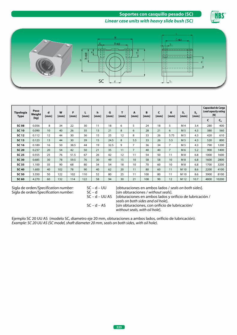
223
Soportes con casquillo pesado (SC)Linear case units with heavy slide bush (SC)
Sigla de orden/Specification number: SC – d – UU [obturaciones en ambos lados / seals on both sides].Sigla de orden/Specification number: SC – d [sin obturaciones / without seals]. SC – d – UU AS [obturaciones en ambos lados y orificio de lubricación / seals on both sides and oil hole]. SC – d – AS [sin obturaciones, con orificio de lubricación/ without seals, with oil hole].
Ejemplo SC 20 UU AS (modelo SC, diametro eje 20 mm, obturaciones a ambos lados, orificio de lubricación).Example: SC 20 UU AS (SC model, shaft diameter 20 mm, seals on both sides, with oil hole).
TipologíaType
PesoWeight
[kg]
d[mm]
W [mm]
F[mm]
L [mm]
h[mm]
G[mm]
T[mm]
A [mm]
B[mm]
C [mm]
K [mm]
S1
[mm]S2
[mm]
Capacidad de Carga Load capacity rating
[N]
C C0
SC 08 0.056 8 34 22 30 11 18 6 5 24 18 5 M 4 3.4 280 400
SC 10 0.090 10 40 26 35 13 21 8 6 28 21 6 M 5 4.3 380 560
SC 12 0.112 12 44 30 36 15 25 12 8 33 26 5.75 M 5 4.3 420 610
SC 13 0.123 13 44 30 39 15 24.5 8 5.5 33 26 5.5 M 5 4.3 520 800
SC 16 0.189 16 50 38.5 44 19 32.5 9 7 36 34 7 M 5 4.3 790 1200
SC 20 0.237 20 54 42 50 21 35 11 7 40 40 7 M 6 5.2 900 1400
SC 25 0.555 25 76 51.5 67 26 42 12 11 54 50 11 M 8 6.8 1000 1600
SC 30 0.685 30 78 59.5 76 30 49 15 10 58 58 10 M 8 6.8 1600 2800
SC 35 1.100 35 90 68 80 34 54 18 10 70 60 10 M 8 6.8 1700 3200
SC 40 1.600 40 102 78 90 40 62 20 11 80 60 11 M 10 8.6 2200 4100
SC 50 3.350 50 122 102 110 52 80 25 11 100 80 11 M 10 8.6 3900 8100
SC 60 4.270 60 132 114 122 58 94 30 21 108 90 12 M 12 10.7 4800 10200
SC
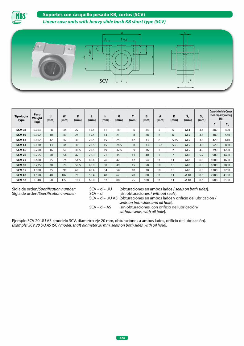
224
Soportes con casquillo pesado KB, cortos (SCV)Linear case units with heavy slide bush KB short type (SCV)
Sigla de orden/Specification number: SCV – d – UU [obturaciones en ambos lados / seals on both sides].Sigla de orden/Specification number: SCV – d [sin obturaciones / without seals]. SCV – d – UU AS [obturaciones en ambos lados y orificio de lubricación / seals on both sides and oil hole]. SCV – d – AS [sin obturaciones, con orificio de lubricación/ without seals, with oil hole].
Ejemplo SCV 20 UU AS (modelo SCV, diametro eje 20 mm, obturaciones a ambos lados, orificio de lubricación).Example: SCV 20 UU AS (SCV model, shaft diameter 20 mm, seals on both sides, with oil hole).
TipologíaType
PesoWeight
[kg]
d[mm]
W [mm]
F[mm]
L [mm]
h[mm]
G[mm]
T[mm]
B[mm]
A [mm]
K [mm]
S1
[mm]S2
[mm]
Capacidad de Carga Load capacity rating
[N]
C C0
SCV 08 0.063 8 34 22 15.4 11 18 6 24 5 5 M 4 3.4 280 400
SCV 10 0.092 10 40 26 19.5 13 21 8 28 6 6 M 5 4.3 380 560
SCV 12 0.102 12 42 30 20.5 15 25 12 33 8 5.75 M 5 4.3 420 610
SCV 13 0.120 13 44 30 20.5 15 24.5 8 33 5.5 5.5 M 5 4.3 520 800
SCV 16 0.200 16 50 38.5 23.5 19 32.5 9 36 7 7 M 5 4.3 790 1200
SCV 20 0.255 20 54 42 28.3 21 35 11 40 7 7 M 6 5.2 900 1400
SCV 25 0.600 25 76 51.5 40.4 26 42 12 54 11 11 M 8 6.8 1000 1600
SCV 30 0.735 30 78 59.5 40.9 30 49 15 58 10 10 M 8 6.8 1600 2800
SCV 35 1.100 35 90 68 45.4 34 54 18 70 10 10 M 8 6.8 1700 3200
SCV 40 1.590 40 102 78 56.4 40 62 20 80 11 11 M 10 8.6 2200 4100
SCV 50 3.340 50 122 102 68.9 52 80 25 100 11 11 M 10 8.6 3900 8100
SCV
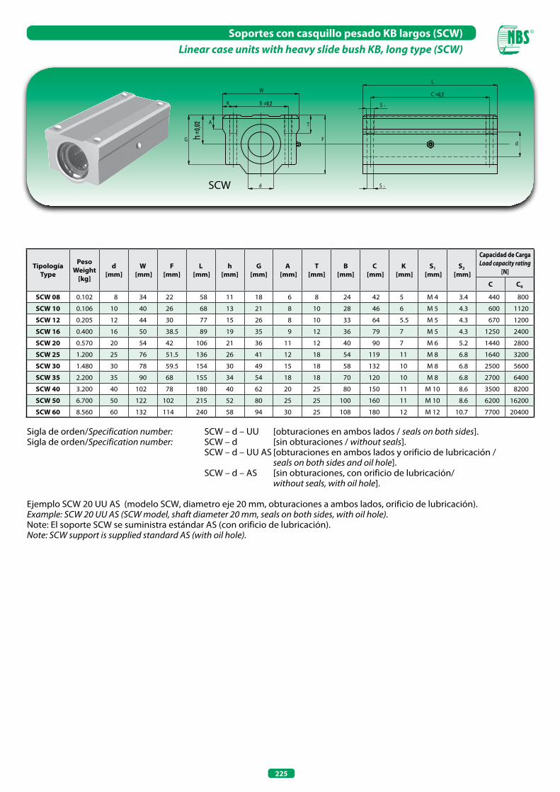
225
Soportes con casquillo pesado KB largos (SCW)Linear case units with heavy slide bush KB, long type (SCW)
SCW
Sigla de orden/Specification number: SCW – d – UU [obturaciones en ambos lados / seals on both sides].Sigla de orden/Specification number: SCW – d [sin obturaciones / without seals]. SCW – d – UU AS [obturaciones en ambos lados y orificio de lubricación / seals on both sides and oil hole]. SCW – d – AS [sin obturaciones, con orificio de lubricación/ without seals, with oil hole].
Ejemplo SCW 20 UU AS (modelo SCW, diametro eje 20 mm, obturaciones a ambos lados, orificio de lubricación).Example: SCW 20 UU AS (SCW model, shaft diameter 20 mm, seals on both sides, with oil hole).Note: El soporte SCW se suministra estándar AS (con orificio de lubricación).Note: SCW support is supplied standard AS (with oil hole).
TipologíaType
PesoWeight
[kg]
d[mm]
W [mm]
F[mm]
L [mm]
h[mm]
G[mm]
A [mm]
T[mm]
B[mm]
C [mm]
K [mm]
S1
[mm]S2
[mm]
Capacidad de Carga Load capacity rating
[N]
C C0
SCW 08 0.102 8 34 22 58 11 18 6 8 24 42 5 M 4 3.4 440 800
SCW 10 0.106 10 40 26 68 13 21 8 10 28 46 6 M 5 4.3 600 1120
SCW 12 0.205 12 44 30 77 15 26 8 10 33 64 5.5 M 5 4.3 670 1200
SCW 16 0.400 16 50 38.5 89 19 35 9 12 36 79 7 M 5 4.3 1250 2400
SCW 20 0.570 20 54 42 106 21 36 11 12 40 90 7 M 6 5.2 1440 2800
SCW 25 1.200 25 76 51.5 136 26 41 12 18 54 119 11 M 8 6.8 1640 3200
SCW 30 1.480 30 78 59.5 154 30 49 15 18 58 132 10 M 8 6.8 2500 5600
SCW 35 2.200 35 90 68 155 34 54 18 18 70 120 10 M 8 6.8 2700 6400
SCW 40 3.200 40 102 78 180 40 62 20 25 80 150 11 M 10 8.6 3500 8200
SCW 50 6.700 50 122 102 215 52 80 25 25 100 160 11 M 10 8.6 6200 16200
SCW 60 8.560 60 132 114 240 58 94 30 25 108 180 12 M 12 10.7 7700 20400
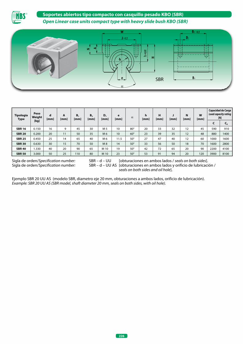
226
Sigla de orden/Specification number: SBR – d – UU [obturaciones en ambos lados / seals on both sides].Sigla de orden/Specification number: SBR – d – UU AS [obturaciones en ambos lados y orificio de lubricación / seals on both sides and oil hole].
Ejemplo SBR 20 UU AS (modelo SBR, diametro eje 20 mm, obturaciones a ambos lados, orificio de lubricación).Example: SBR 20 UU AS (SBR model, shaft diameter 20 mm, seals on both sides, with oil hole).
TipologíaType
PesoWeight
[kg]
d[mm]
A[mm]
B1
[mm]B2
[mm]D1
[mm]e
[mm] a h[mm]
H[mm]
J[mm]
N[mm]
W[mm]
Capacidad de Carga Load capacity rating
[N]
C C0
SBR 16 0.150 16 9 45 30 M 5 10 80° 20 33 32 12 45 590 910
SBR 20 0.200 20 11 50 35 M 6 10 60° 23 39 35 12 48 880 1400
SBR 25 0.450 25 14 65 40 M 6 11.5 50° 27 47 40 12 60 1000 1600
SBR 30 0.630 30 15 70 50 M 8 14 50° 33 56 50 18 70 1600 2800
SBR 40 1.330 40 20 90 65 M 10 19 50° 42 72 65 20 90 2200 4100
SBR 50 3.000 50 25 110 80 M 10 23 50° 53 91 94 20 120 3900 8100
Soportes abiertos tipo compacto con casquillo pesado KBO (SBR)Open Linear case units compact type with heavy slide bush KBO (SBR)
SBR
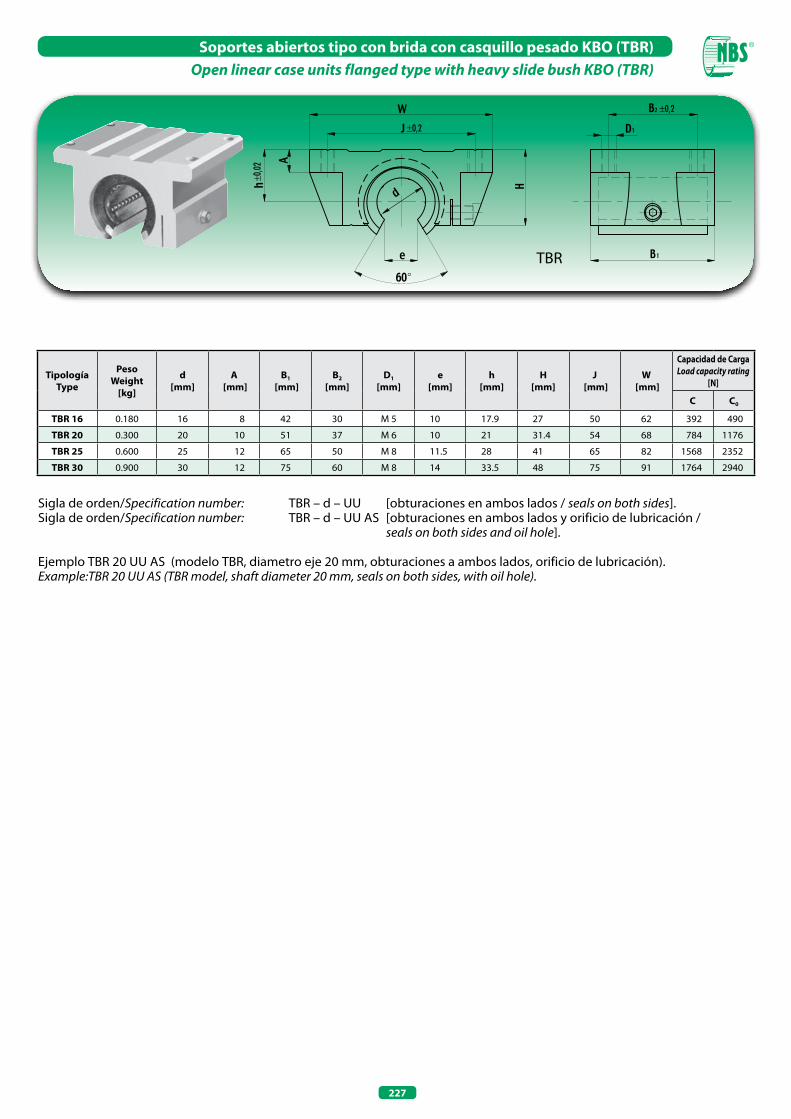
227
Soportes abiertos tipo con brida con casquillo pesado KBO (TBR) Open linear case units flanged type with heavy slide bush KBO (TBR)
TBR
Sigla de orden/Specification number: TBR – d – UU [obturaciones en ambos lados / seals on both sides].Sigla de orden/Specification number: TBR – d – UU AS [obturaciones en ambos lados y orificio de lubricación / seals on both sides and oil hole]. Ejemplo TBR 20 UU AS (modelo TBR, diametro eje 20 mm, obturaciones a ambos lados, orificio de lubricación).Example:TBR 20 UU AS (TBR model, shaft diameter 20 mm, seals on both sides, with oil hole).
TipologíaType
PesoWeight
[kg]
d[mm]
A [mm]
B1
[mm]B2
[mm]D1
[mm]e
[mm]h
[mm]H
[mm]J
[mm]W
[mm]
Capacidad de Carga Load capacity rating
[N]
C C0
TBR 16 0.180 16 8 42 30 M 5 10 17.9 27 50 62 392 490
TBR 20 0.300 20 10 51 37 M 6 10 21 31.4 54 68 784 1176
TBR 25 0.600 25 12 65 50 M 8 11.5 28 41 65 82 1568 2352
TBR 30 0.900 30 12 75 60 M 8 14 33.5 48 75 91 1764 2940
°
±0,2
±0,02
±0,2

NOTAS - NOTES

NOTAS - NOTES

©Copyright
Está prohibida la reproducción, incluso parcial, del contenido de este Catálogo Técnico. No se acepta ningún tipo de responsabilidad en caso de errores u omisiones. Las medidas no son vinculantes. Marca registrada Italia-EU.
The reproduction, even partial, of thecontained concerning this technicalcatalogue, is forbidden. Liability forpossible errors and/or omissionsare not accepted. Sizes are not binding.TM Registered in Italy-EU.
RODAMIENTOS DE AGUJASNEEDLE BEARINGS
79991033
01.07.2012 ©Copyright