remote sensing: introduction4dvarenkf.cima.fcen.uba.ar/course/download/velasco_remotesensin… ·...
TRANSCRIPT
Remote Sensing: IntroductionRemote Sensing: Introduction
Inés Velasco
Departamento de Ciencias de la Atmósfera y los OcéanosFacultad de Ciencias Exactas y Naturales
Universidad de Buenos Aires- UBA
Curso Intensivo sobre Asimilación de Datos27 de Octubre - 7 de Noviembre de 2008
Aula Magna, Pabellon I , Ciudad UniversitariaBuenos Aires, Argentina
Satellite remote sensing is an important complementary tool for observing Earth’s atmosphere and land and ocean surfaces, especially where in-situ observations are scarce or nonexistent.
Why Remote Sensing?
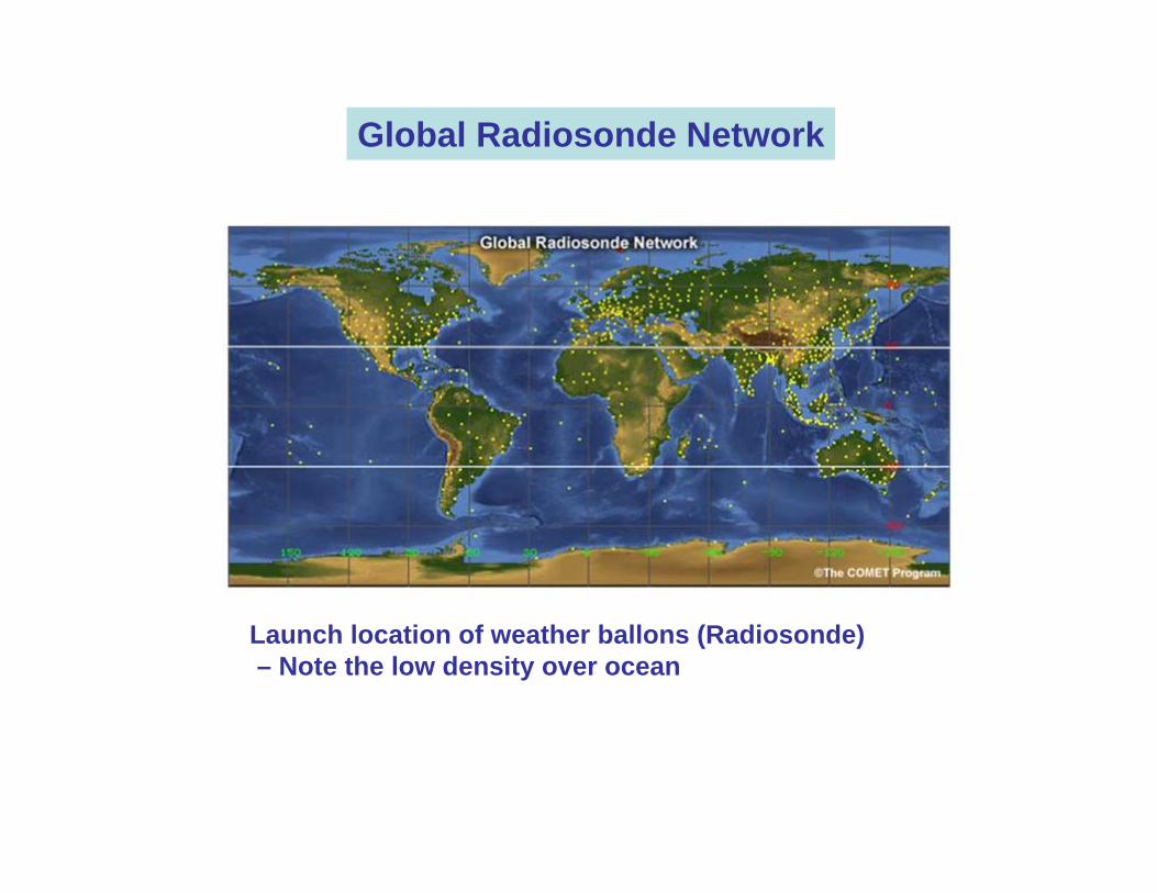
Launch location of weather ballons (Radiosonde)– Note the low density over ocean
Global Radiosonde Network
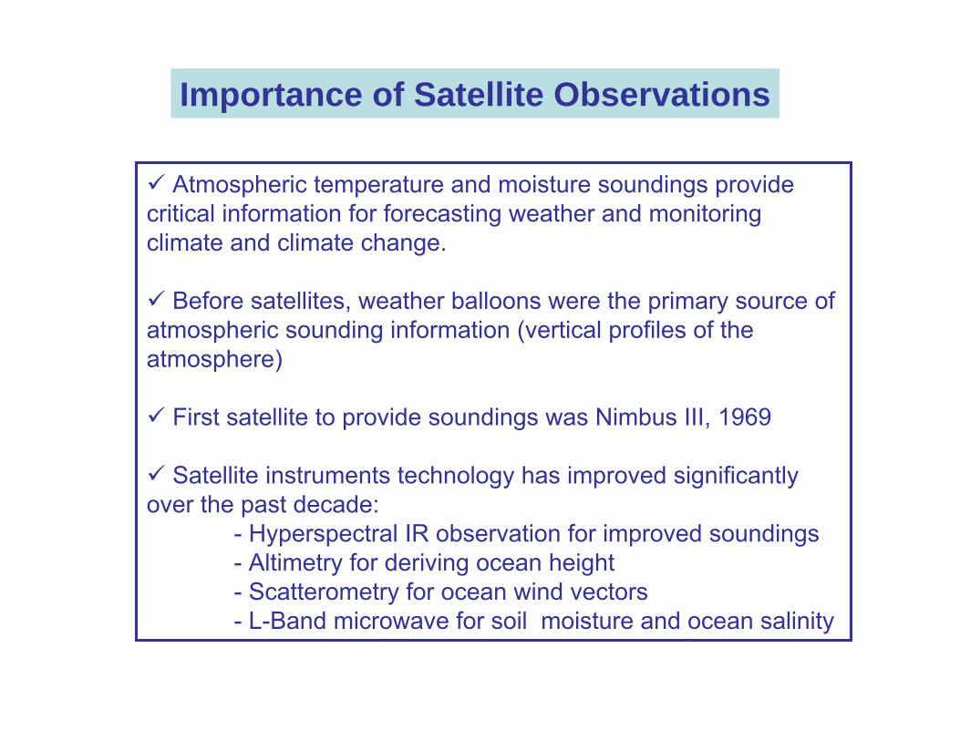
Importance of Satellite Observations
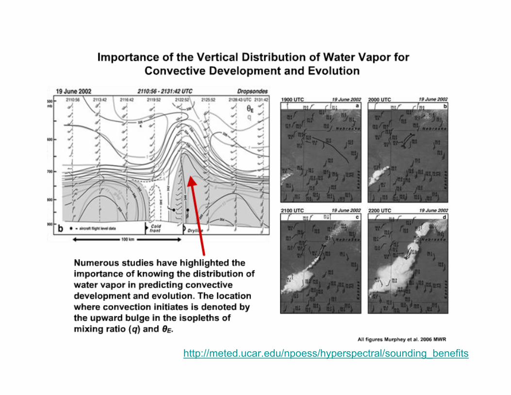
Atmospheric temperature and moisture soundings provide critical information for forecasting weather and monitoring climate and climate change.
Before satellites, weather balloons were the primary source of atmospheric sounding information (vertical profiles of the atmosphere)
First satellite to provide soundings was Nimbus III, 1969
Satellite instruments technology has improved significantly over the past decade:
- Hyperspectral IR observation for improved soundings- Altimetry for deriving ocean height- Scatterometry for ocean wind vectors- L-Band microwave for soil moisture and ocean salinity
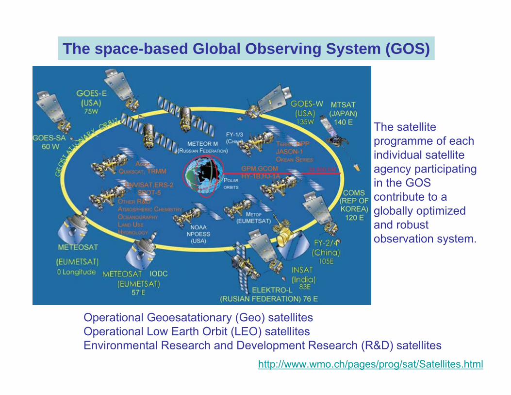
The space-based Global Observing System (GOS)
The satellite programme of each individual satellite agency participating in the GOS contribute to a globally optimized and robust observation system.
Operational Geoesatationary (Geo) satellitesOperational Low Earth Orbit (LEO) satellitesEnvironmental Research and Development Research (R&D) satellites
http://www.wmo.ch/pages/prog/sat/Satellites.html
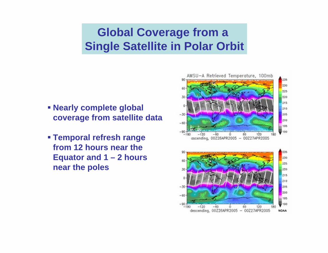
Global Coverage from a Single Satellite in Polar Orbit
Nearly complete global coverage from satellite data
Temporal refresh range from 12 hours near the Equator and 1 – 2 hours near the poles
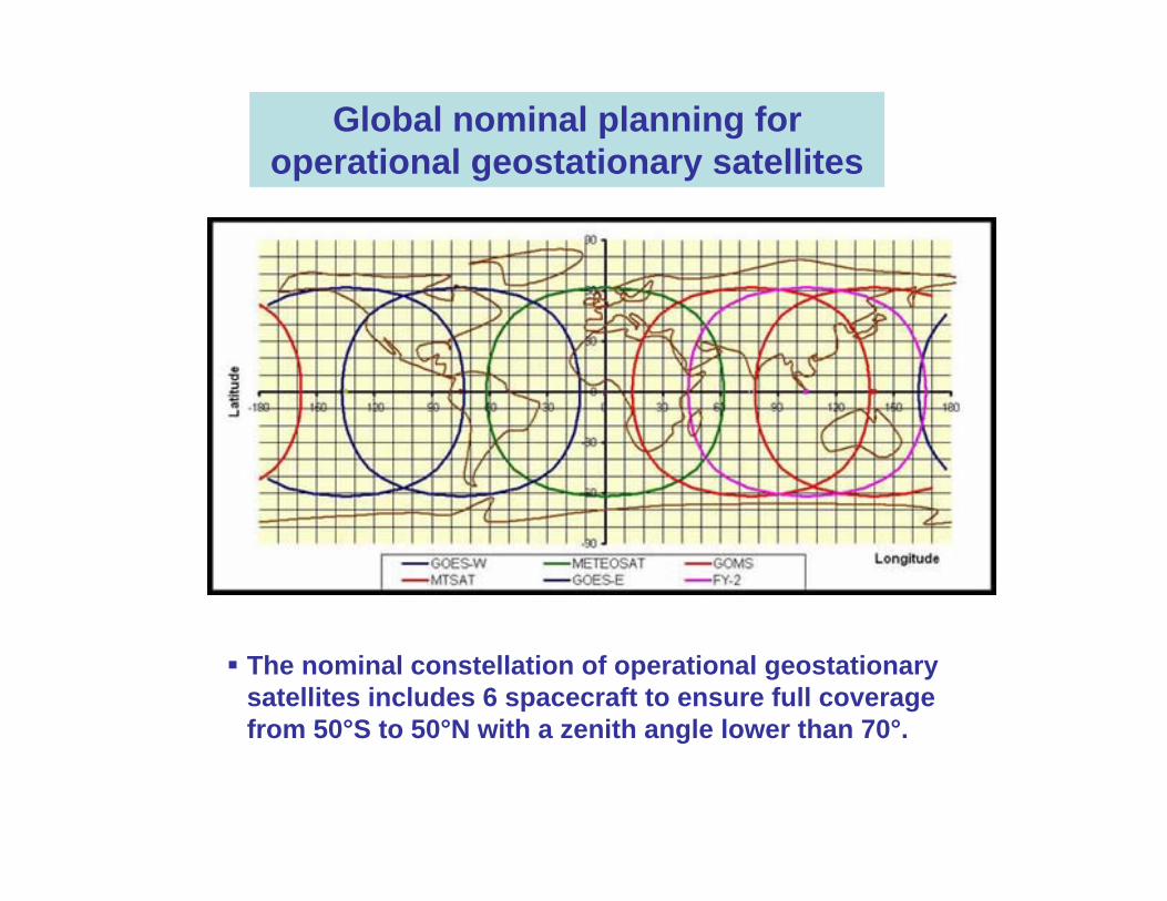
The nominal constellation of operational geostationary satellites includes 6 spacecraft to ensure full coverage from 50°S to 50°N with a zenith angle lower than 70°.
Global nominal planning for operational geostationary satellites
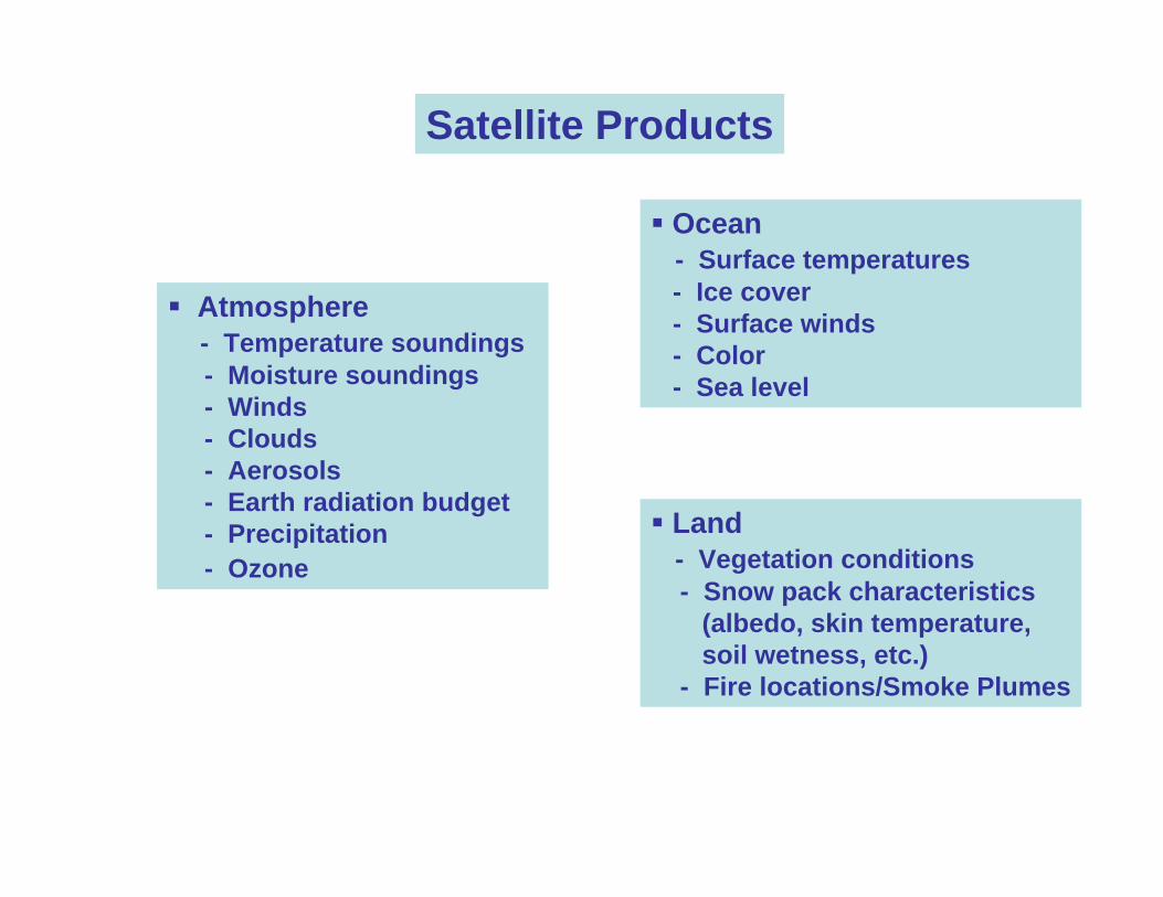
Satellite Products
Atmosphere- Temperature soundings- Moisture soundings- Winds- Clouds- Aerosols- Earth radiation budget- Precipitation- Ozone
Ocean- Surface temperatures- Ice cover- Surface winds- Color- Sea level
Land- Vegetation conditions- Snow pack characteristics
(albedo, skin temperature,soil wetness, etc.)
- Fire locations/Smoke Plumes
Remote Sensing Principles
The term "remote sensing" describe the science and art of identifying, observing, and measuring a system without coming into direct contact with it.
This process involves the detection and measurement of radiation at various wavelengths of the electromagnetic spectrum.
Radiation can be reflected or emitted from distant objects or materials, by which they may be identified and categorized by class/type, substance, and spatial distribution.
http://earthobservatory.nasa.gov/Library/RemoteSensing/
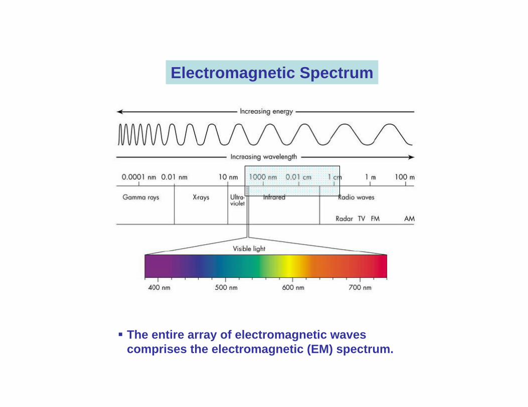
The entire array of electromagnetic waves comprises the electromagnetic (EM) spectrum.
Electromagnetic Spectrum
Unless it has a temperature of absolute zero (-273°C) an object reflects, absorbs, and emits energy in a unique way, and at all times.
This energy, called electromagnetic radiation, is emitted in waves that are able to transmit energy from one place to another.
These waves originate from billions of vibrating electrons, atoms, and molecules, which emit and absorb electromagnetic radiation in unique combinations of wavelengths.
The amount of electromagnetic radiation an object emits depends primarily on its temperature. The higher the temperature of an object, the faster its electrons vibrate and the shorter its peak wavelength of emitted radiation
.
Radiation 1/2
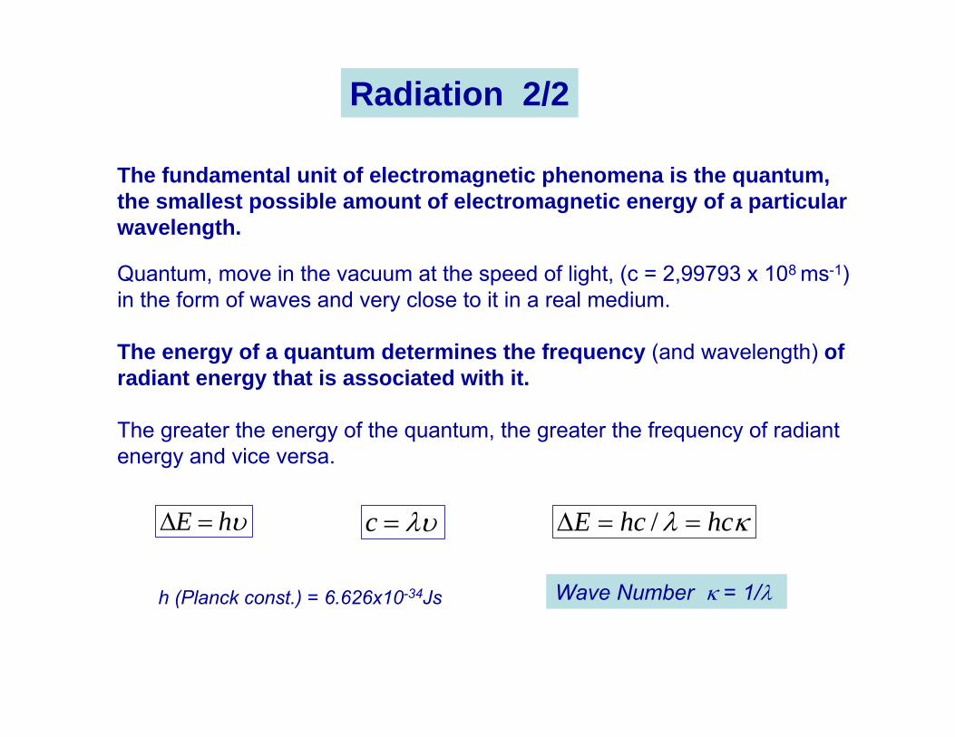
The fundamental unit of electromagnetic phenomena is the quantum, the smallest possible amount of electromagnetic energy of a particular wavelength.
Quantum, move in the vacuum at the speed of light, (c = 2,99793 x 10⁸ ms-1)in the form of waves and very close to it in a real medium.
The energy of a quantum determines the frequency (and wavelength) of radiant energy that is associated with it.
The greater the energy of the quantum, the greater the frequency of radiant energy and vice versa.
υhE =∆ κλ hchcE ==∆ /λυ=c
h (Planck const.) = 6.626x10⁻³⁴Js Wave Number κ = 1/λ
Radiation 2/2
Radiation can interact with atmospheric gases in five ways:
1. Ionization-dissociation interactions2. Electronic transitions3. Vibrational transitions4. Rotacional transitions and5. Forbidden transitions
Vibrational transitions occur mostly in the IR
Rotacional transitions occur in the far IR and microwave
and both can occur simultaneously
Radiative interactions
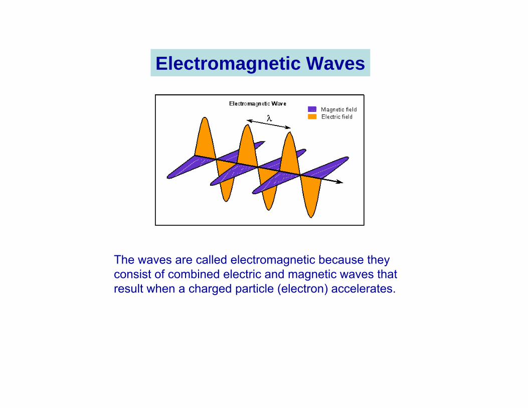
The waves are called electromagnetic because they consist of combined electric and magnetic waves that result when a charged particle (electron) accelerates.
Electromagnetic Waves
The basic principle associated with remote sensing of the atmospheric temperature and humidity structure involves the interpretation of radiometric measurements of electromagnetic radiation in specific spectral intervalswhich are sensitive to some physical aspects of the medium.
More specifically, at any wavenumber (or wavelength) in the infrared or microwave regions where an atmospheric constituent absorbs radiation, it also emits thermal radiation according to Kirchhoff's Law.
Since the radiance leaving the atmosphere is a function of the distribution of the emitting gases and of temperature throughout the atmosphere, measurements of radiance contain some information on both these quantities.
Remote sensing of the atmosphere
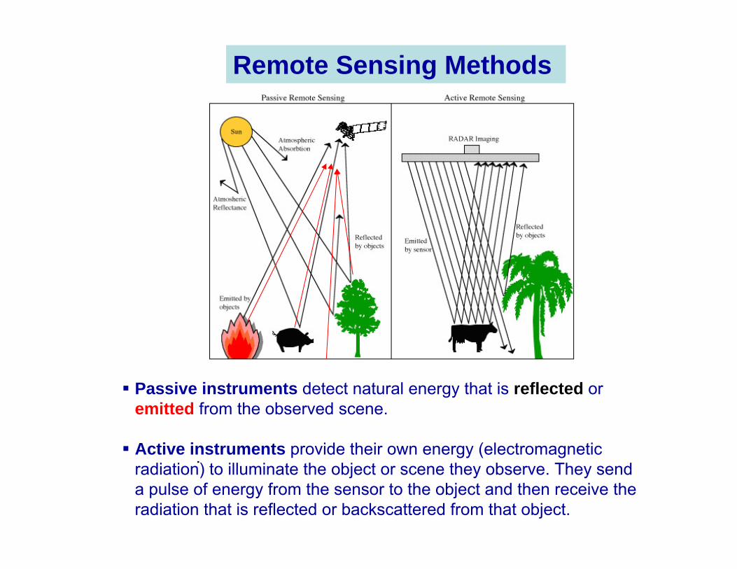
Passive instruments detect natural energy that is reflected or emitted from the observed scene.
Active instruments provide their own energy (electromagnetic radiation) to illuminate the object or scene they observe. They send a pulse of energy from the sensor to the object and then receive the radiation that is reflected or backscattered from that object.
Remote Sensing Methods
.
λθδ λ
λ dddtdAEL
Ω=
cos
[Watt sr-1 m-2 µm-1]
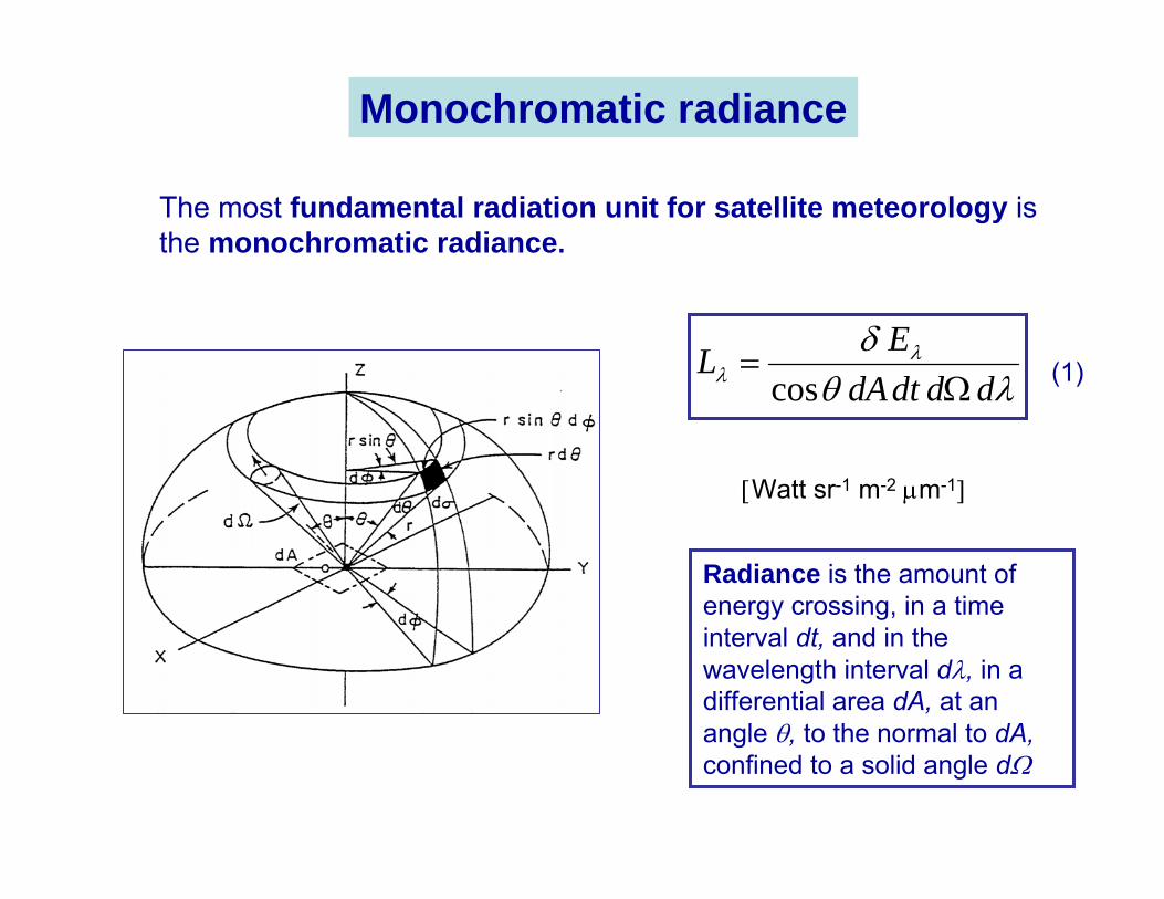
Radiance is the amount of energy crossing, in a time interval dt, and in the wavelength interval dλ, in a differential area dA, at an angle θ, to the normal to dA, confined to a solid angle dΩ
The most fundamental radiation unit for satellite meteorology is the monochromatic radiance.
(1)
Monochromatic radiance
52
1
2 −
−= λ
λ
λ
)kThcexp(
hc)T(B
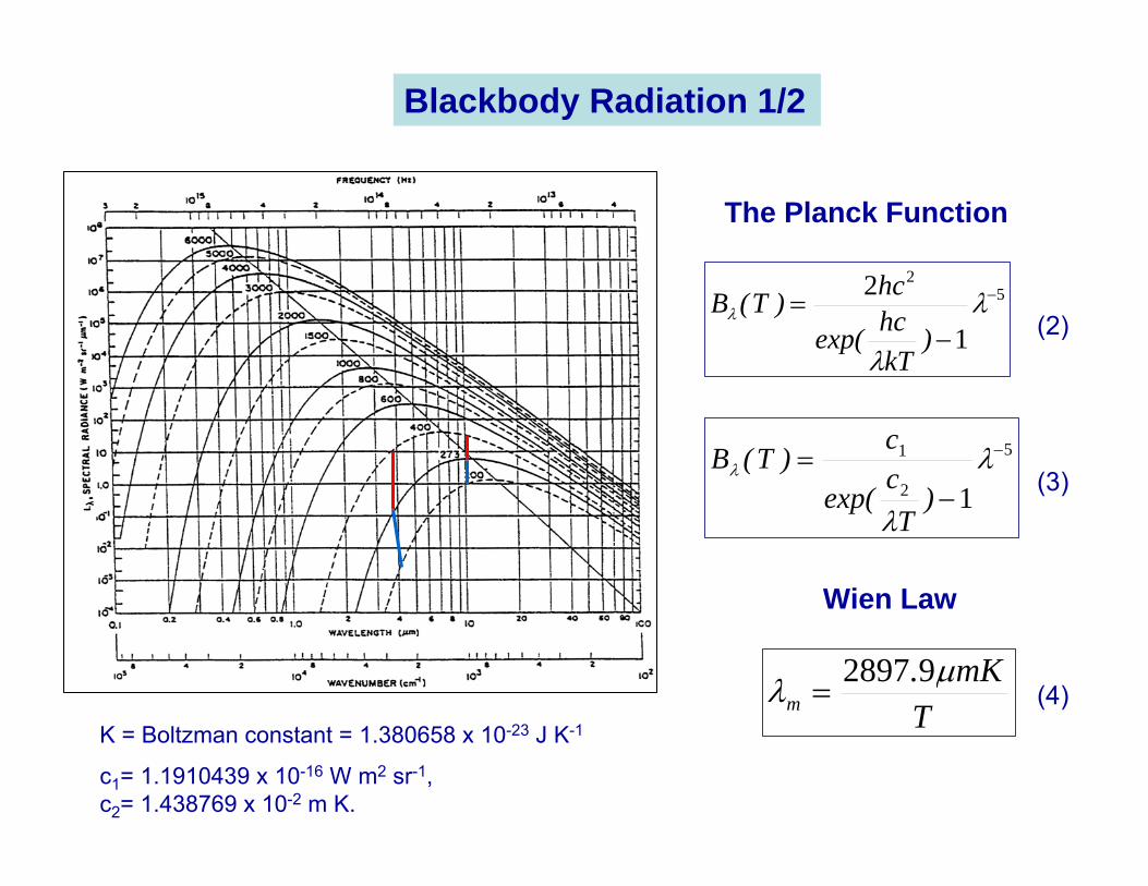
K = Boltzman constant = 1.380658 x 10⁻²³ J K-1
Blackbody Radiation 1/2
5
2
1
1
−
−= λ
λ
λ
)T
cexp(
c)T(B
c1= 1.1910439 x 10⁻¹⁶ W m2 sr-1, c2= 1.438769 x 10⁻² m K.
TmK.
mµλ 92897
=
Wien Law
(2)
(3)
(4)
The Planck Function
)(TBM BB λλ π=
4TM BB σ=
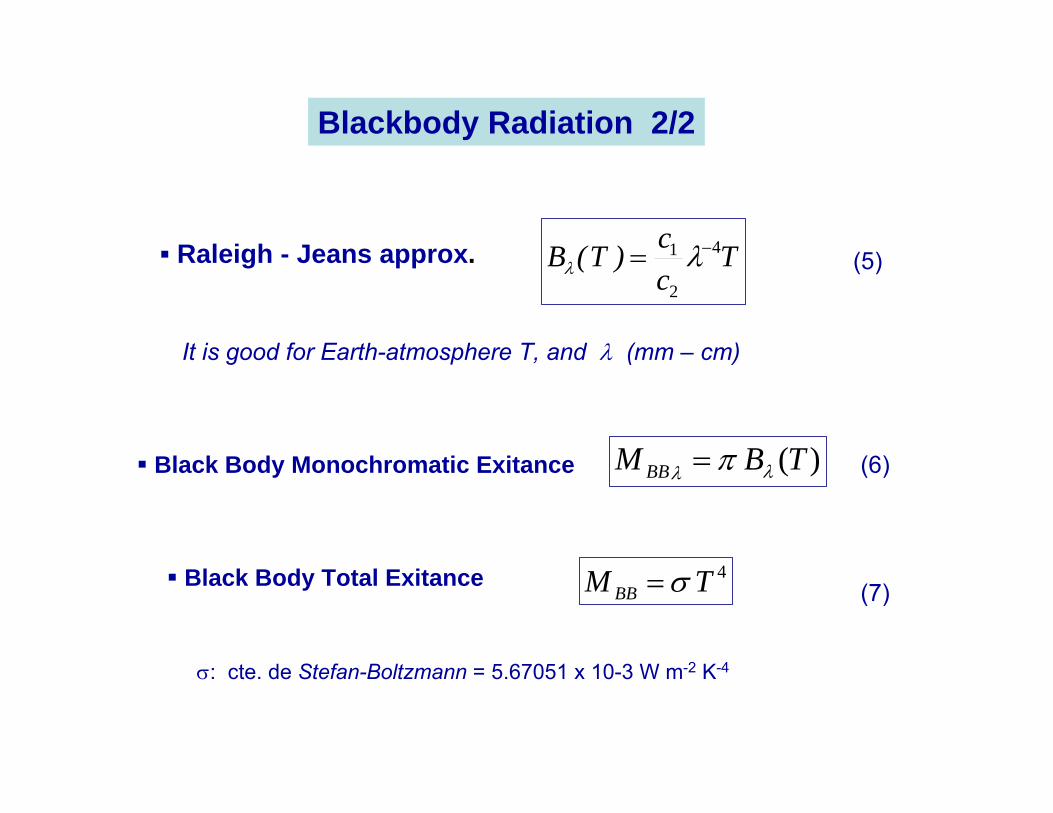
σ: cte. de Stefan-Boltzmann = 5.67051 x 10⁻³ W m-2 K-4
Black Body Monochromatic Exitance
Black Body Total Exitance
(6)
(7)
Blackbody Radiation 2/2
Raleigh - Jeans approx. Tcc)T(B 4
2
1 −= λλ
It is good for Earth-atmosphere T, and λ (mm – cm)
(5)
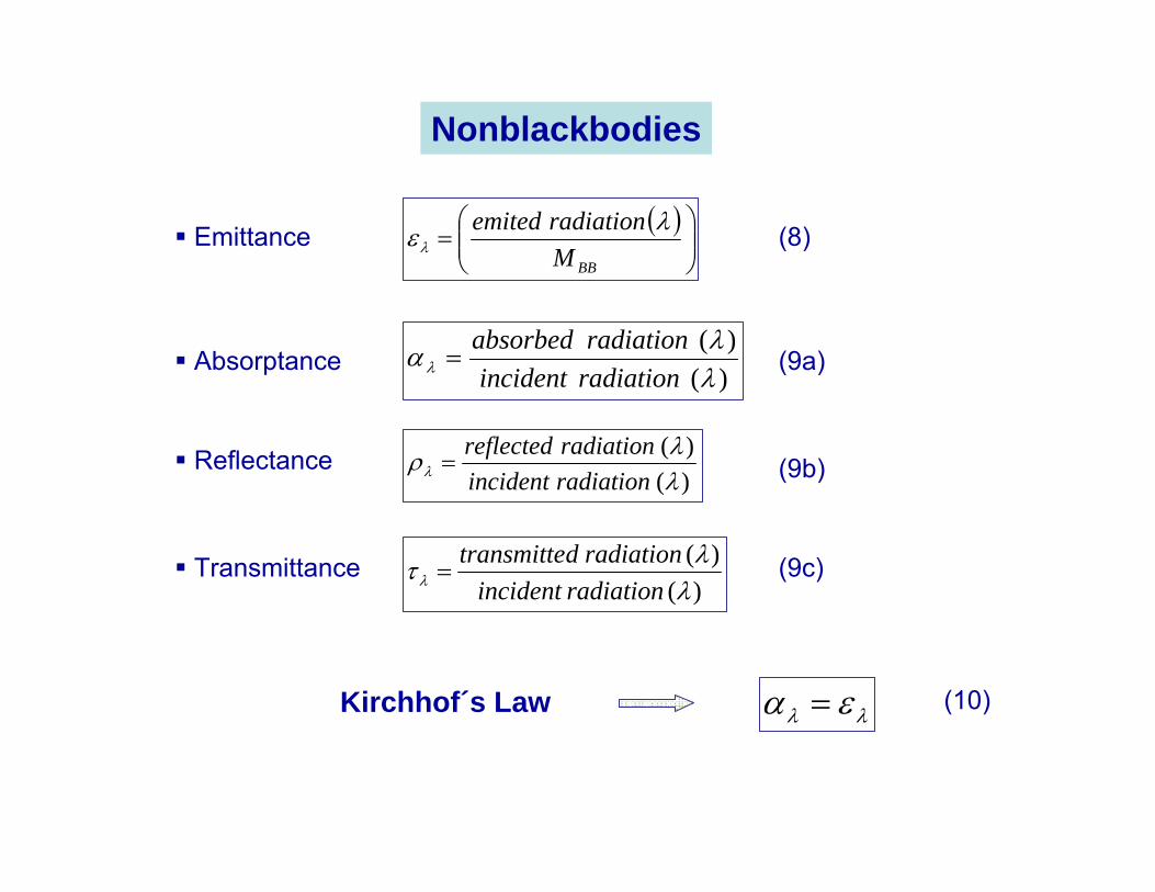
Nonblackbodies
( )⎟⎟⎠
⎞⎜⎜⎝
⎛=
BBMradiationemited λελEmittance
Kirchhof´s Law λλ εα =
)()(
λλαλ radiationincident
radiationabsorbed=
)()(
λλρλ radiationincident
radiationreflected=
)()(
λλτλ radiationincident
radiationdtransmitte=
Absorptance
Reflectance
Transmittance
(8)
(9a)
(9b)
(9c)
(10)
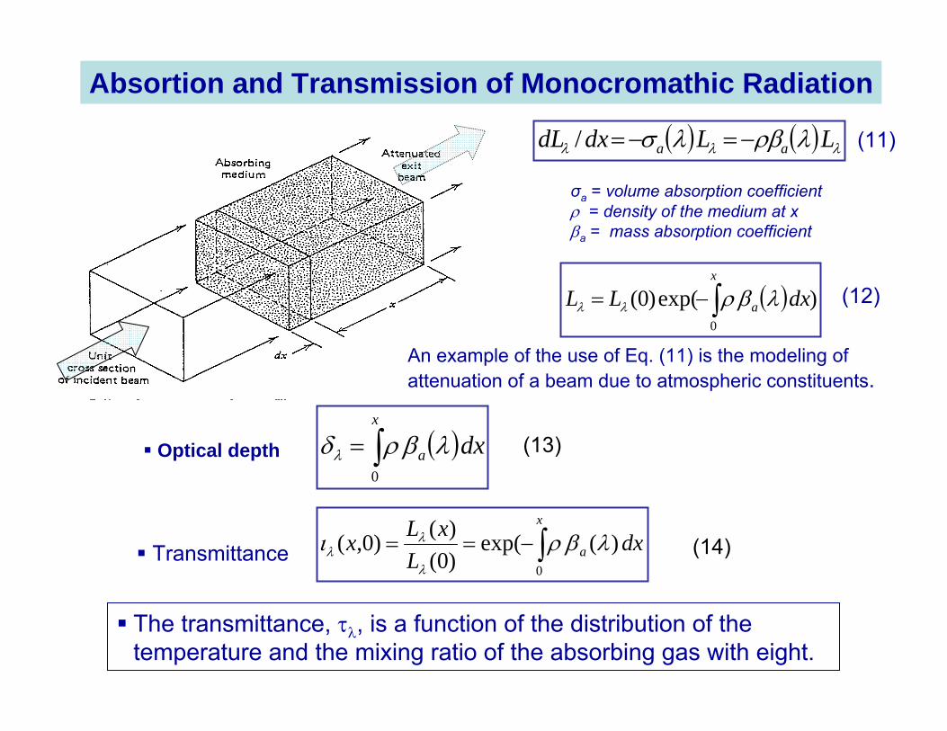
( ) ( ) λλλ λρβλσ LLdxdL aa −=−=/
σa = volume absorption coefficientρ = density of the medium at xβa = mass absorption coefficient
( ) )exp()0(0
dxLLx
a∫−= λβρλλ
( )dxx
a∫=0
λβρδλOptical depth
dxL
xLxx
a )(exp()0()()0,(
0
λβριλ
λλ ∫−==Transmittance
An example of the use of Eq. (11) is the modeling of attenuation of a beam due to atmospheric constituents.
(11)
(12)
(13)
(14)
Absortion and Transmission of Monocromathic Radiation
The transmittance, τλ, is a function of the distribution of the temperature and the mixing ratio of the absorbing gas with eight.
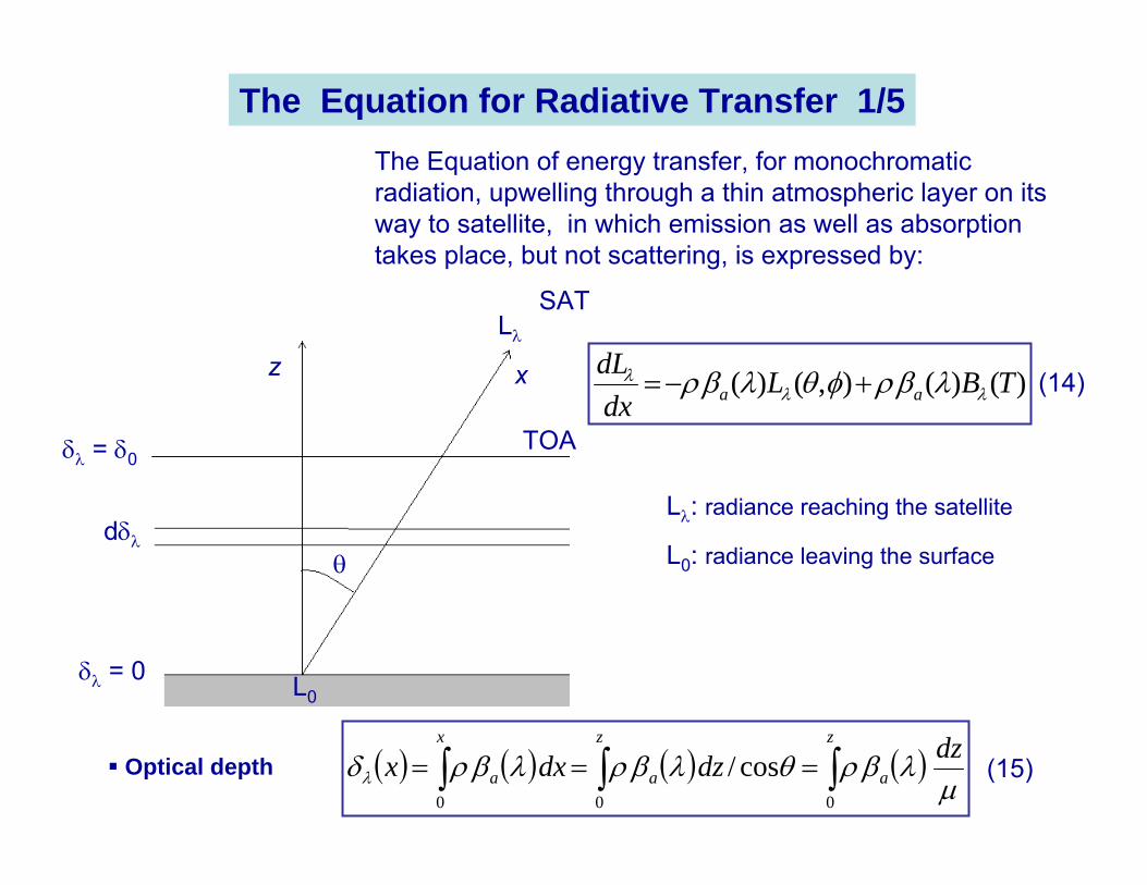
L0: radiance leaving the surface
Lλ: radiance reaching the satellite
( ) ( ) ( ) ( )µ
λβρθλβρλβρδλdzdzdxx
z
a
z
a
x
a ∫∫∫ ===000
cos/
z
δλ = 0
Lλ
θdδλ
δλ = δ0
L0
x
TOA
SAT
The Equation for Radiative Transfer 1/5The Equation of energy transfer, for monochromatic radiation, upwelling through a thin atmospheric layer on its way to satellite, in which emission as well as absorption takes place, but not scattering, is expressed by:
)()(),()( TBLdxdL
aa λλλ λβρφθλβρ +−=
Optical depth
(14)
(15)
( ) ( )TB,LddL
λλλ
λ φθδ
µ +−=
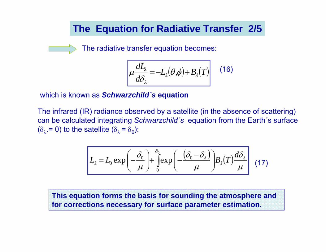
The radiative transfer equation becomes:
which is known as Schwarzchild´s equation
The infrared (IR) radiance observed by a satellite (in the absence of scattering) can be calculated integrating Schwarzchild´s equation from the Earth´s surface (δλ.= 0) to the satellite (δλ = δ0):
( ) ( )µδ
µδδ
µδ λ
λ
δλ
λdTBLL ∫ ⎟⎟
⎠
⎞⎜⎜⎝
⎛ −−+⎟⎟
⎠
⎞⎜⎜⎝
⎛−=
0
0
000 expexp
This equation forms the basis for sounding the atmosphere and for corrections necessary for surface parameter estimation.
(16)
(17)
The Equation for Radiative Transfer 2/5
( ) ( )µδ
µδδ
µδ λ
λ
δλ
λdTBLL ∫ ⎟⎟
⎠
⎞⎜⎜⎝
⎛ −−+⎟⎟
⎠
⎞⎜⎜⎝
⎛−=
0
0
000 expexp
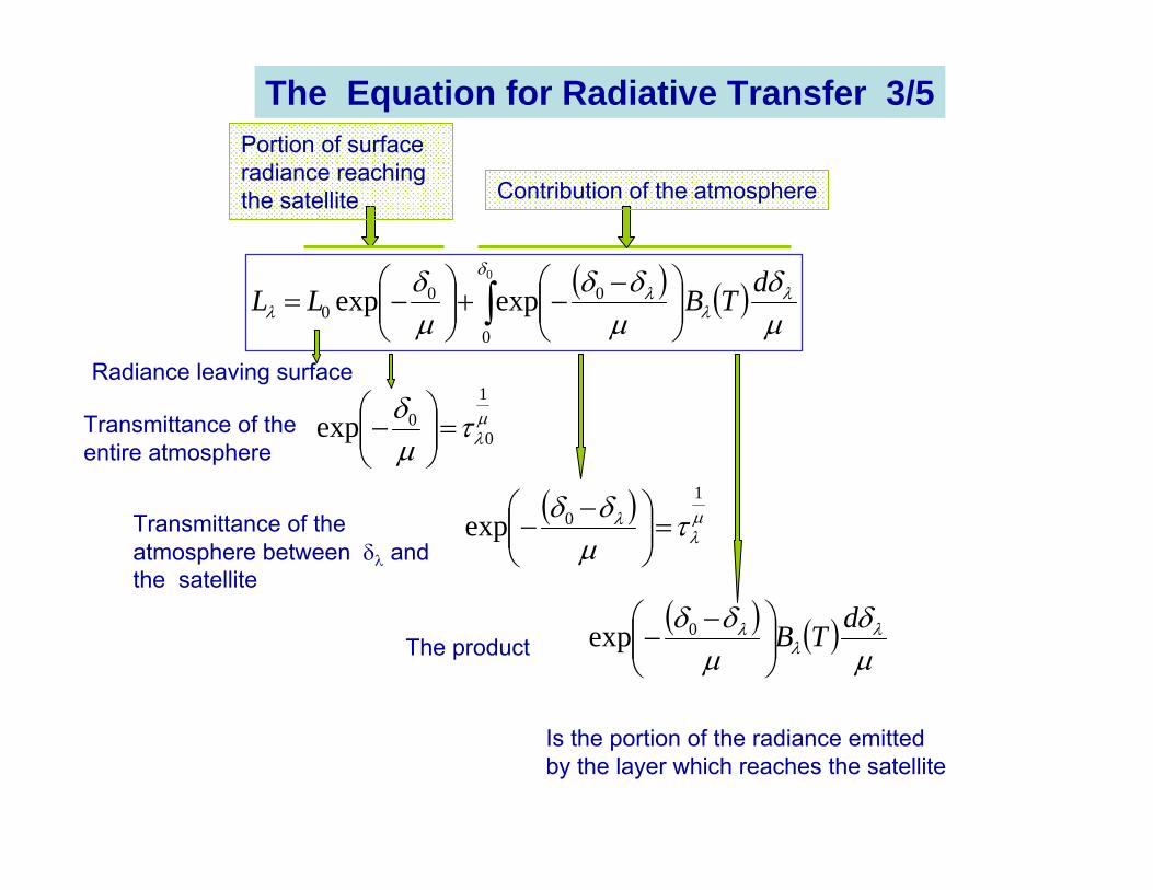
Portion of surface radiance reaching the satellite Contribution of the atmosphere
µλτµ
δ 1
00exp =⎟⎟⎠
⎞⎜⎜⎝
⎛−
( ) µλ
λ τµδδ 1
0exp =⎟⎟⎠
⎞⎜⎜⎝
⎛ −−
Transmittance of the entire atmosphere
Transmittance of the atmosphere between δλ and the satellite
( ) ( )µδ
µδδ λ
λλ dTB⎟⎟⎠
⎞⎜⎜⎝
⎛ −− 0expThe product
Is the portion of the radiance emitted by the layer which reaches the satellite
Radiance leaving surface
The Equation for Radiative Transfer 3/5
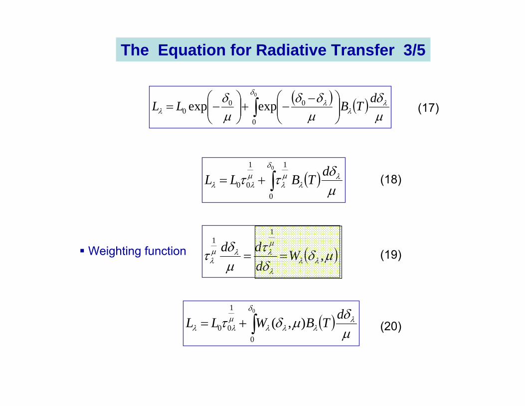
( )µδττ λ
λ
δµλ
µλλ
dTBLL ∫+=0
0
11
00
( ) ( )µδ
µδδ
µδ λ
λ
δλ
λdTBLL ∫ ⎟⎟
⎠
⎞⎜⎜⎝
⎛ −−+⎟⎟
⎠
⎞⎜⎜⎝
⎛−=
0
0
000 expexp
( )µδδτ
µδτ λλ
λ
µλλµ
λ ,
11
Wddd
==
( )µδµδτ λ
δ
λλλµλλ
dTBWLL ∫+=0
0
1
00 ),(
Weighting function
(17)
(19)
(20)
(18)
The Equation for Radiative Transfer 3/5
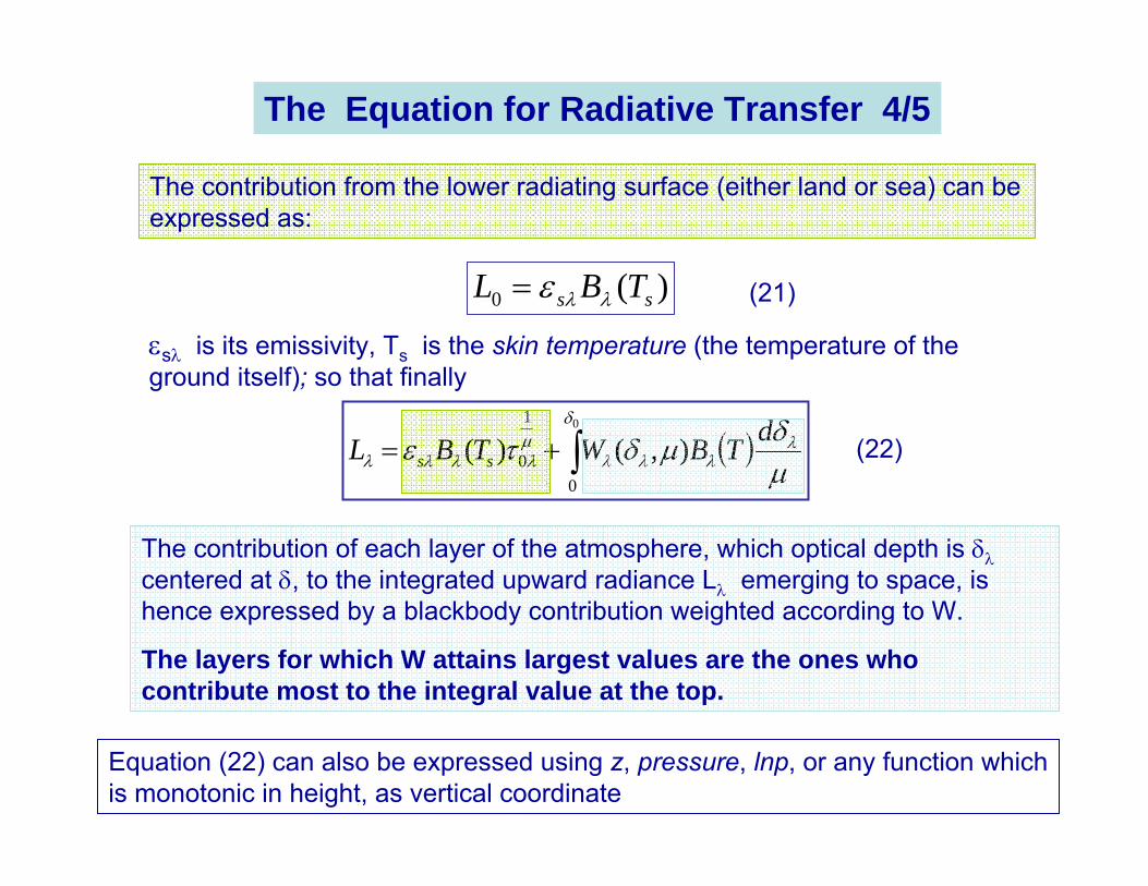
( )µδµδτε λ
δ
λλλµλλλλ
dTBWTBL ss ∫+=0
0
1
0 ),()(
The contribution of each layer of the atmosphere, which optical depth is δλcentered at δ, to the integrated upward radiance Lλ emerging to space, is hence expressed by a blackbody contribution weighted according to W.
The layers for which W attains largest values are the ones who contribute most to the integral value at the top.
Equation (22) can also be expressed using z, pressure, lnp, or any function which is monotonic in height, as vertical coordinate
The contribution from the lower radiating surface (either land or sea) can be expressed as:
)(0 ss TBL λλε=
εsλ is its emissivity, Ts is the skin temperature (the temperature of the ground itself); so that finally
(21)
(22)
The Equation for Radiative Transfer 4/5
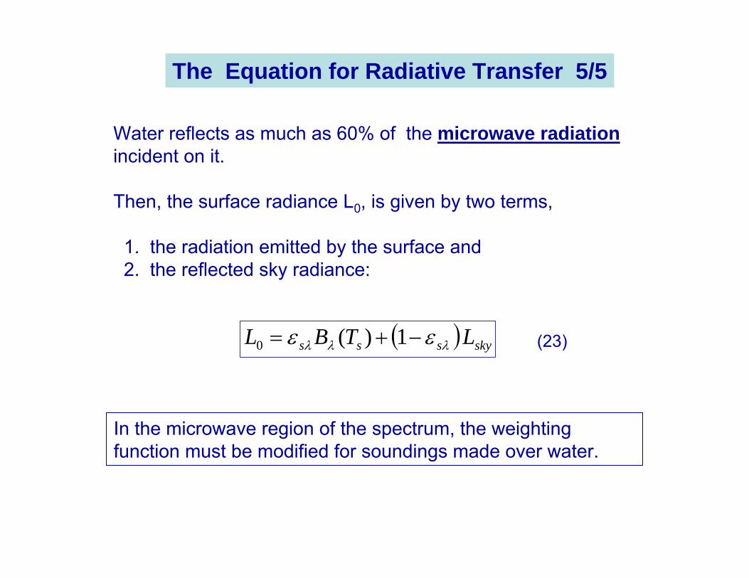
Water reflects as much as 60% of the microwave radiationincident on it.
Then, the surface radiance L0, is given by two terms,
1. the radiation emitted by the surface and2. the reflected sky radiance:
( ) skysss LTBL λλλ εε −+= 1)(0
In the microwave region of the spectrum, the weighting function must be modified for soundings made over water.
(23)
The Equation for Radiative Transfer 5/5
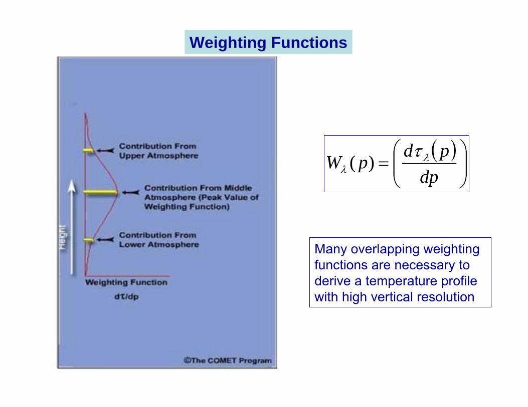
( )⎟⎟⎠
⎞⎜⎜⎝
⎛=
dppdpW λ
λτ)(
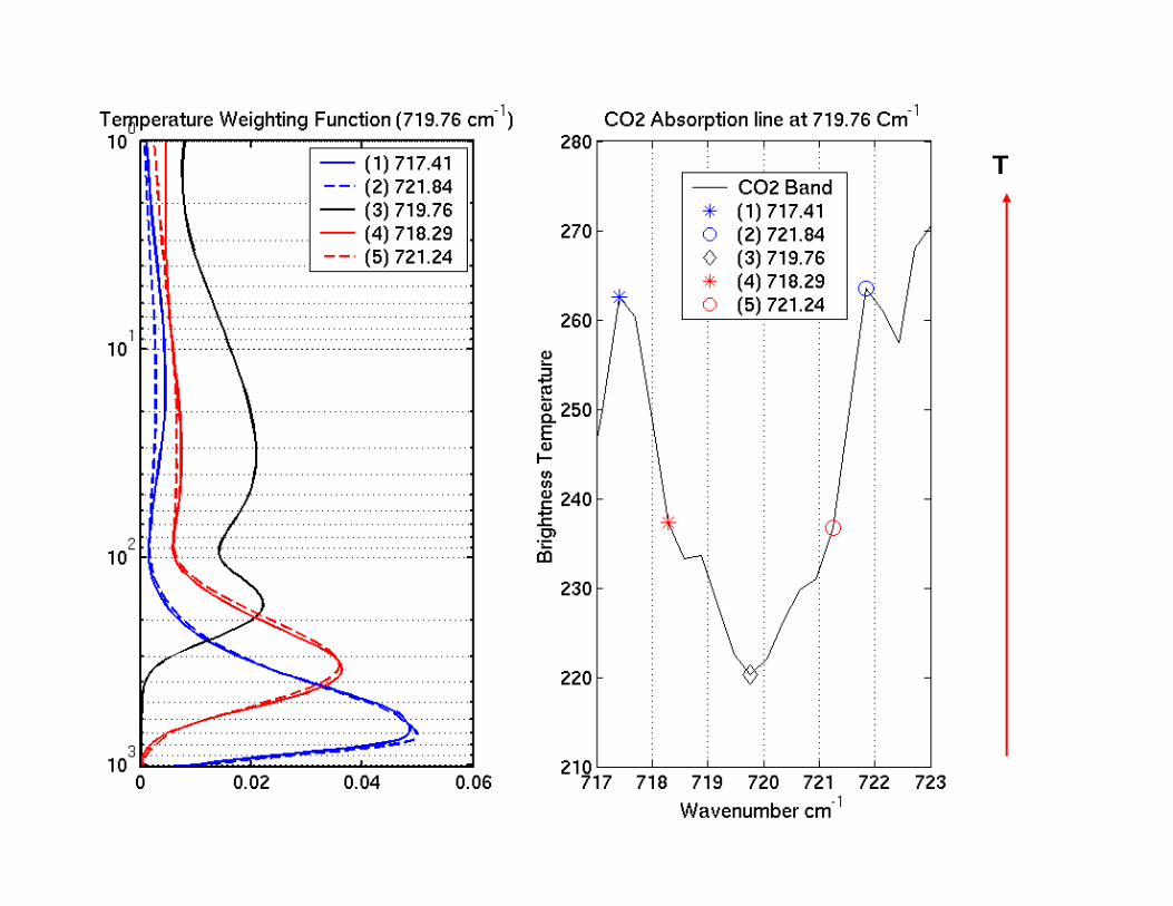
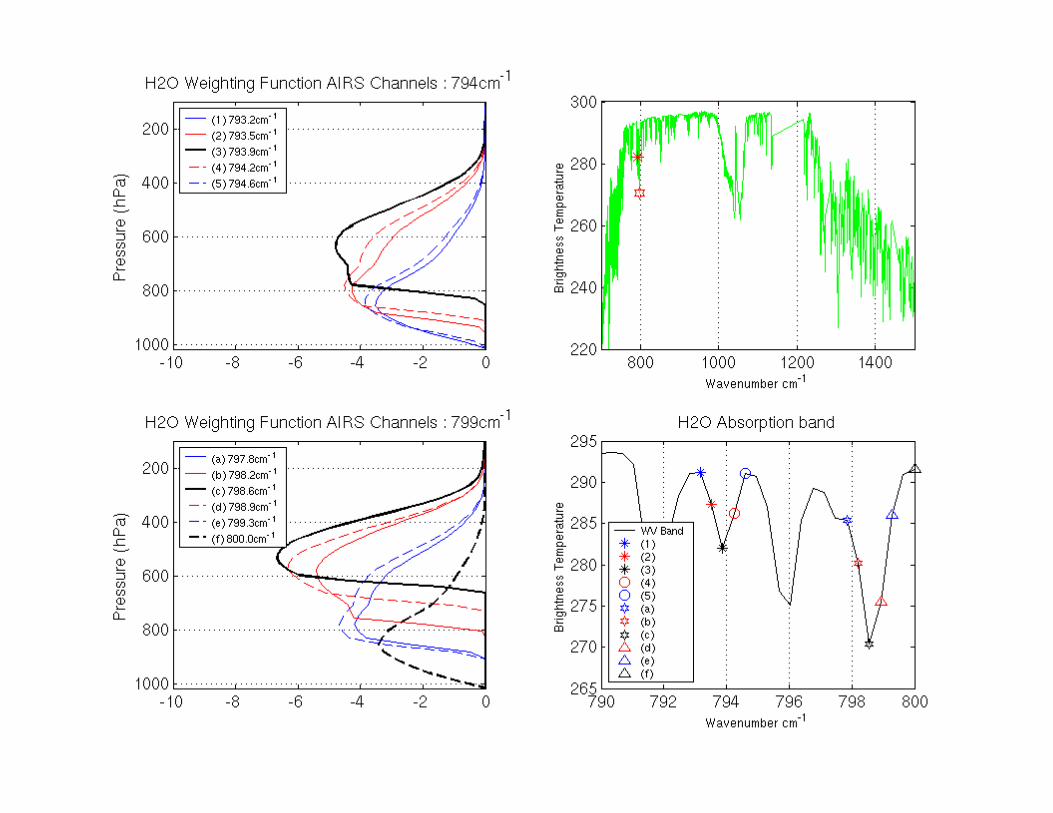
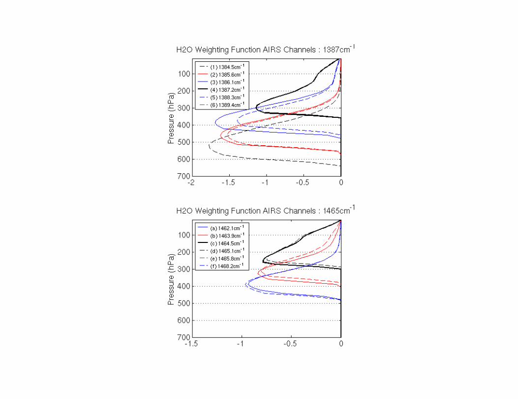
Many overlapping weighting functions are necessary to derive a temperature profile with high vertical resolution
Weighting Functions
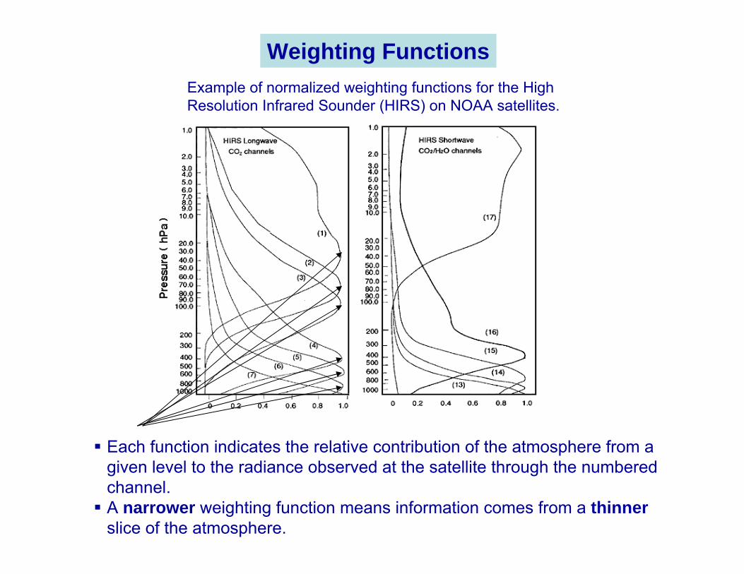
Each function indicates the relative contribution of the atmosphere from a given level to the radiance observed at the satellite through the numbered channel. A narrower weighting function means information comes from a thinner slice of the atmosphere.
Example of normalized weighting functions for the High Resolution Infrared Sounder (HIRS) on NOAA satellites.
Weighting Functions
The instrument makes measurements of radiance in a number of channels.
For each channel, we can write a radiative transfer equation.
This equation expresses the DIRECT PROBLEM for the channel, i.e. given the state of the atmosphere, the solution ofthis equation tells us the radiance incident at the satellite in this channel.
However, when presented with satellite measurements, we are faced with the INVERSE PROBLEM: given the measurements (Lλ), what is the state of the atmosphere (in terms of its vertical profiles of temperature and constituents).
The direct and inverse problems
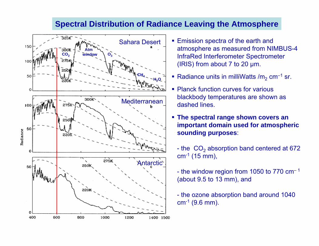
Emission spectra of the earth and atmosphere as measured from NIMBUS-4 InfraRed Interferometer Spectrometer (IRIS) from about 7 to 20 µm.
Radiance units in milliWatts /m2 cm–1 sr.
Planck function curves for various blackbody temperatures are shown as dashed lines.
The spectral range shown covers an important domain used for atmospheric sounding purposes:
- the CO2 absorption band centered at 672 cm-1 (15 mm),
- the window region from 1050 to 770 cm– 1
(about 9.5 to 13 mm), and
- the ozone absorption band around 1040 cm-1 (9.6 mm).
Spectral Distribution of Radiance Leaving the Atmosphere
Sahara Desert
Mediterranean
Antarctic
CO2
Atmwindow O3
CH4H2O
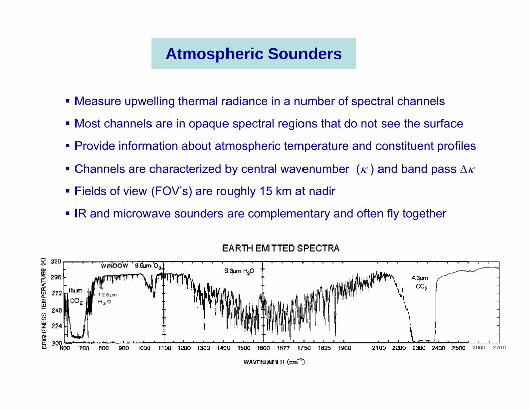
Measure upwelling thermal radiance in a number of spectral channels
Most channels are in opaque spectral regions that do not see the surface
Provide information about atmospheric temperature and constituent profiles
Channels are characterized by central wavenumber (κ ) and band pass ∆κ
Fields of view (FOV’s) are roughly 15 km at nadir
IR and microwave sounders are complementary and often fly together
Atmospheric Sounders
High Spectral Resolution IR Sounding from Space
AIRS, IASI, soon followed by CrIS
AIRS (Atmospheric Infrared Sounder)
IASI (Infrared Atmospheric Sounding Interferometer)
CrIS (Cross-track Infrared Sounder)
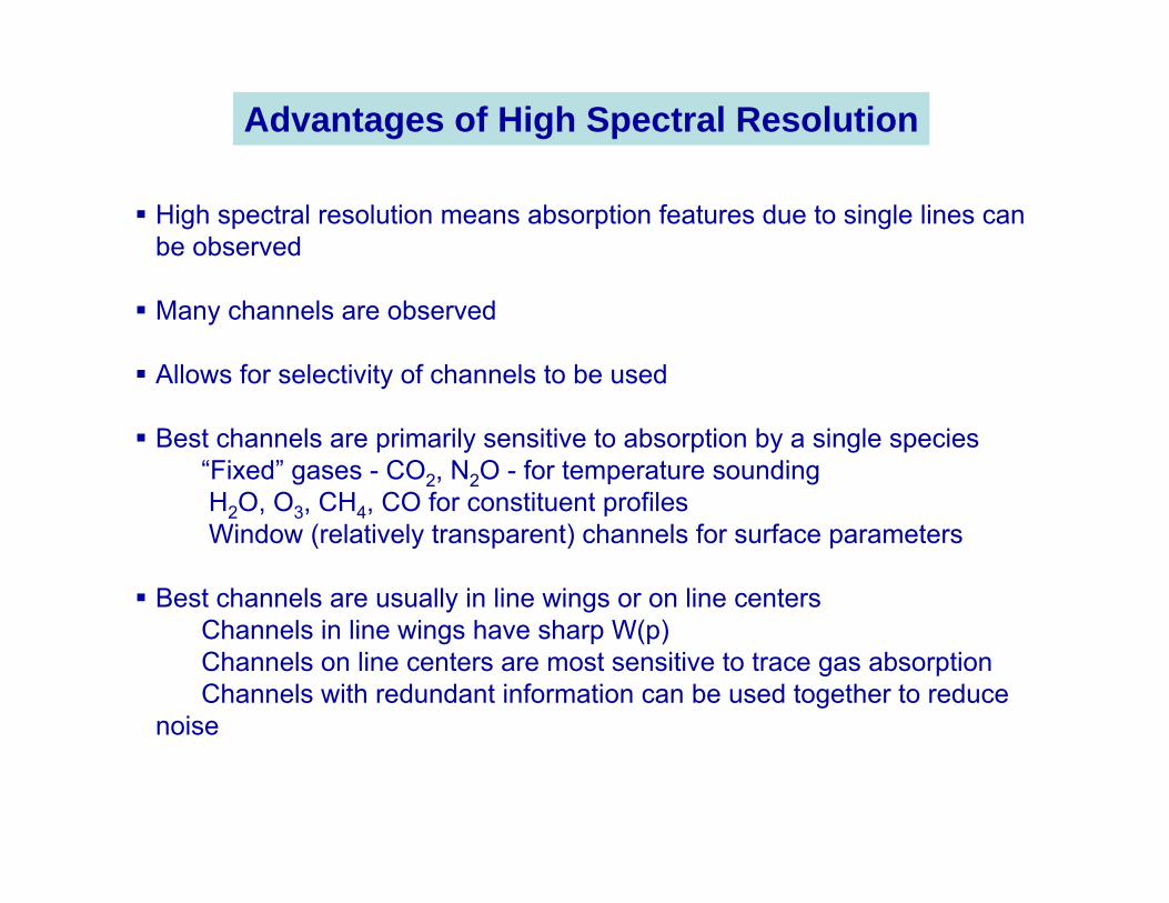
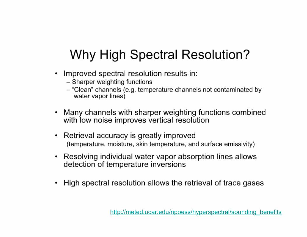
Advantages of High Spectral Resolution
High spectral resolution means absorption features due to single lines can be observed
Many channels are observed
Allows for selectivity of channels to be used
Best channels are primarily sensitive to absorption by a single species“Fixed” gases - CO2, N2O - for temperature soundingH2O, O3, CH4, CO for constituent profilesWindow (relatively transparent) channels for surface parameters
Best channels are usually in line wings or on line centersChannels in line wings have sharp W(p)Channels on line centers are most sensitive to trace gas absorptionChannels with redundant information can be used together to reduce
noise
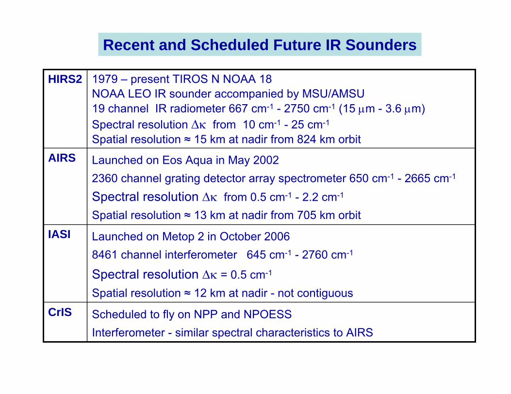
Recent and Scheduled Future IR Sounders
Scheduled to fly on NPP and NPOESSInterferometer - similar spectral characteristics to AIRS
CrIS
Launched on Metop 2 in October 20068461 channel interferometer 645 cm-1 - 2760 cm-1
Spectral resolution ∆κ = 0.5 cm-1
Spatial resolution ≈ 12 km at nadir - not contiguous
IASI
Launched on Eos Aqua in May 20022360 channel grating detector array spectrometer 650 cm-1 - 2665 cm-1
Spectral resolution ∆κ from 0.5 cm-1 - 2.2 cm-1
Spatial resolution ≈ 13 km at nadir from 705 km orbit
AIRS
1979 – present TIROS N NOAA 18NOAA LEO IR sounder accompanied by MSU/AMSU19 channel IR radiometer 667 cm-1 - 2750 cm-1 (15 µm - 3.6 µm)Spectral resolution ∆κ from 10 cm-1 - 25 cm-1
Spatial resolution ≈ 15 km at nadir from 824 km orbit
HIRS2
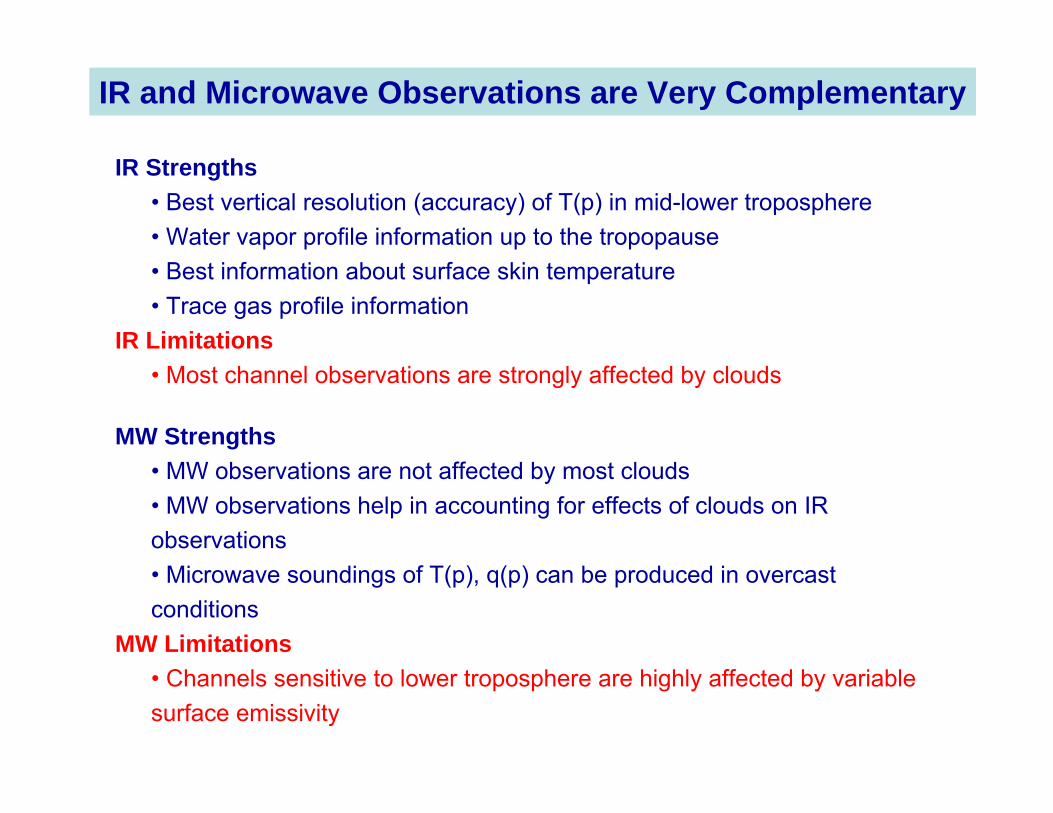
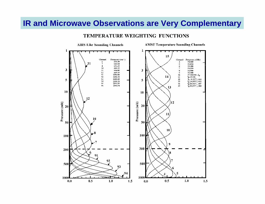
IR and Microwave Observations are Very Complementary
IR Strengths• Best vertical resolution (accuracy) of T(p) in mid-lower troposphere• Water vapor profile information up to the tropopause• Best information about surface skin temperature• Trace gas profile information
IR Limitations• Most channel observations are strongly affected by clouds
MW Strengths• MW observations are not affected by most clouds• MW observations help in accounting for effects of clouds on IR observations• Microwave soundings of T(p), q(p) can be produced in overcast conditions
MW Limitations• Channels sensitive to lower troposphere are highly affected by variable surface emissivity
IR and Microwave Observations are Very Complementary
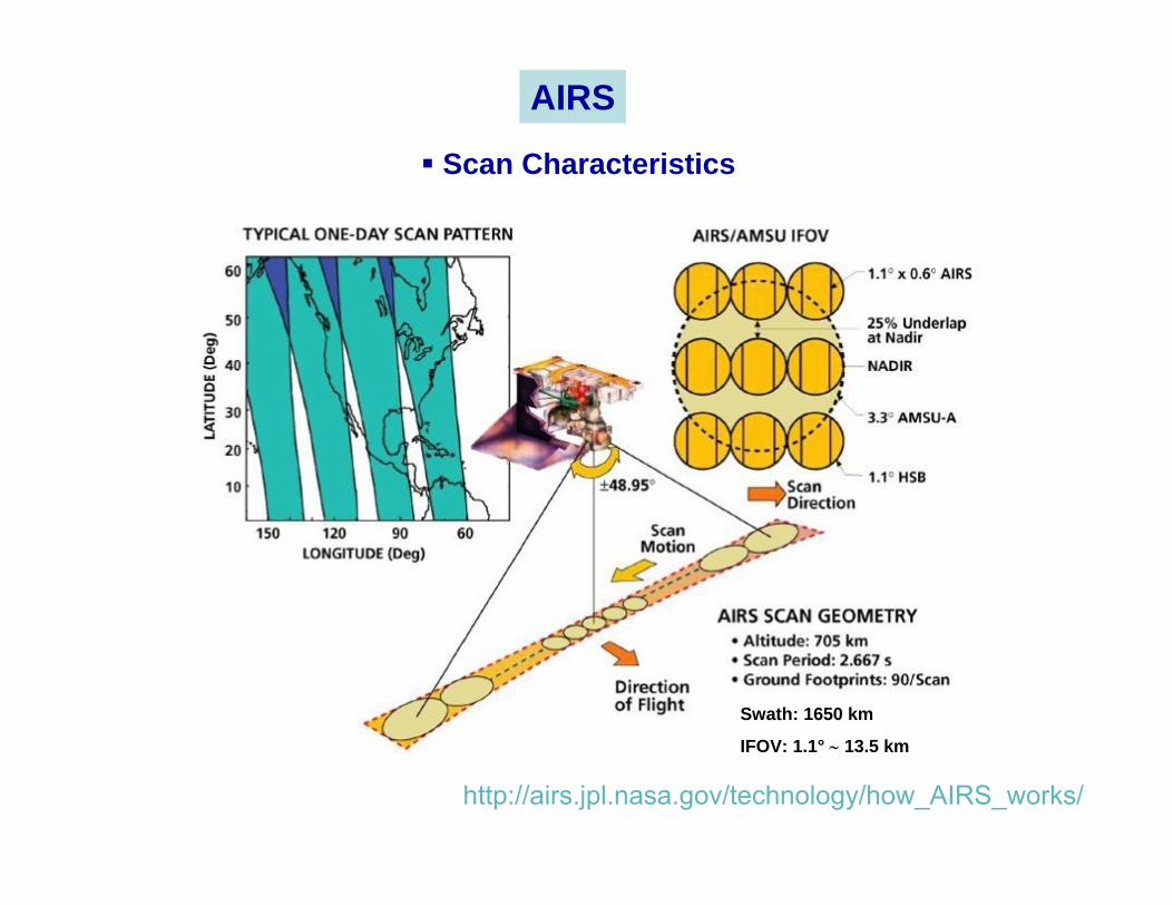
http://airs.jpl.nasa.gov/technology/how_AIRS_works/
Swath: 1650 km
IFOV: 1.1° ∼ 13.5 km
AIRS
Scan Characteristics
AIRS is a high spectral resolution spectrometer with 2378 bands in the thermal infrared (3.7 - 15.4 µm) and 4 bands in the visible (0.4 - 1.0 µm).
These ranges have been specifically selected to allow determination in the troposphere of:
- atmospheric temperature with an accuracy of 1°C in layers 1 km thick,
- humidity with an accuracy of 20% in layers 2 km thick .
In the cross-track direction, a ±49.5 degree swath centered on the nadir.
Each scan line contains 90 IR footprints, with a resolution of
- 13.5 km at nadir and
- 41km x 21.4 km at the scan extremes
from nominal 705.3 km orbit.
The Vis/NIR spatial resolution is approximately 2.3 km at nadir.
AIRS general characteristics
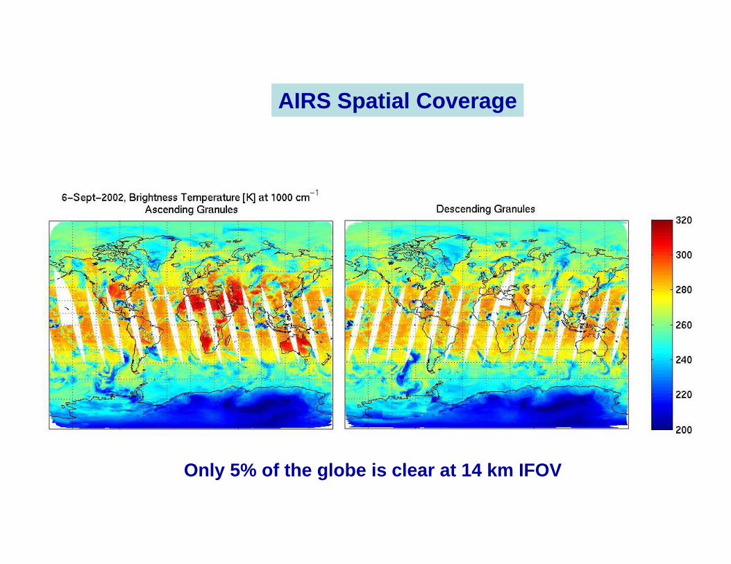
AIRS Spatial Coverage
Only 5% of the globe is clear at 14 km IFOV
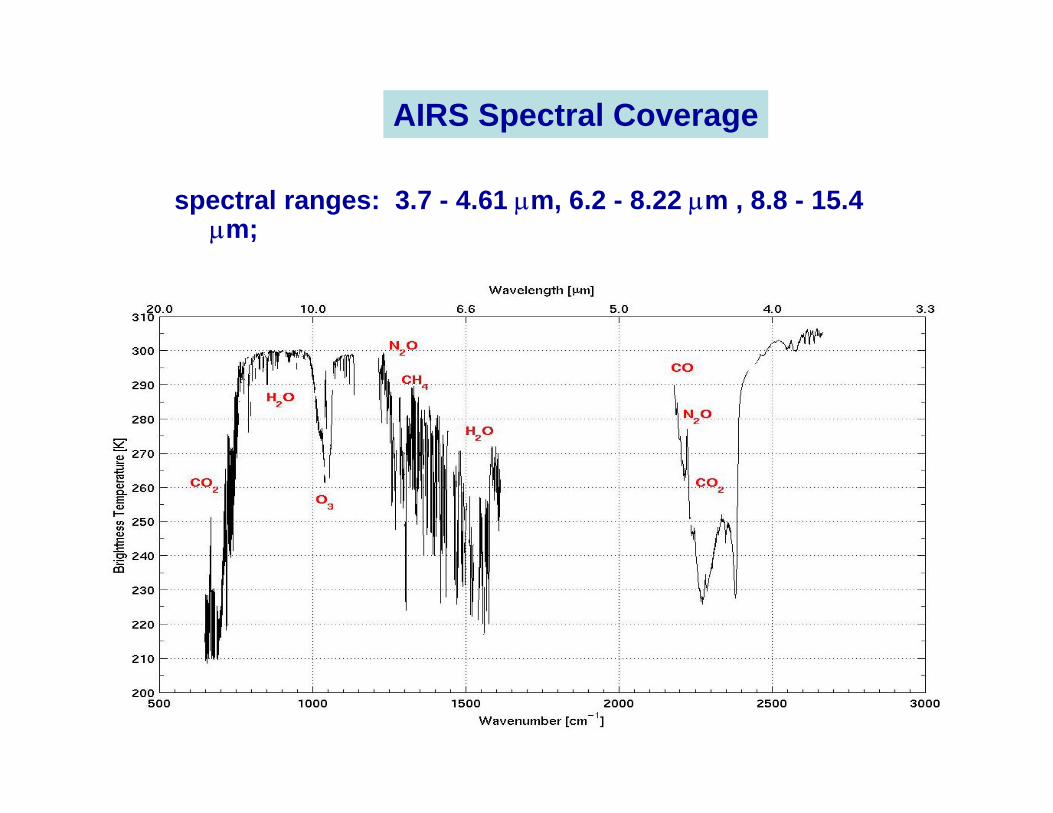
spectral ranges: 3.7 - 4.61 µm, 6.2 - 8.22 µm , 8.8 - 15.4 µm;
AIRS Spectral Coverage
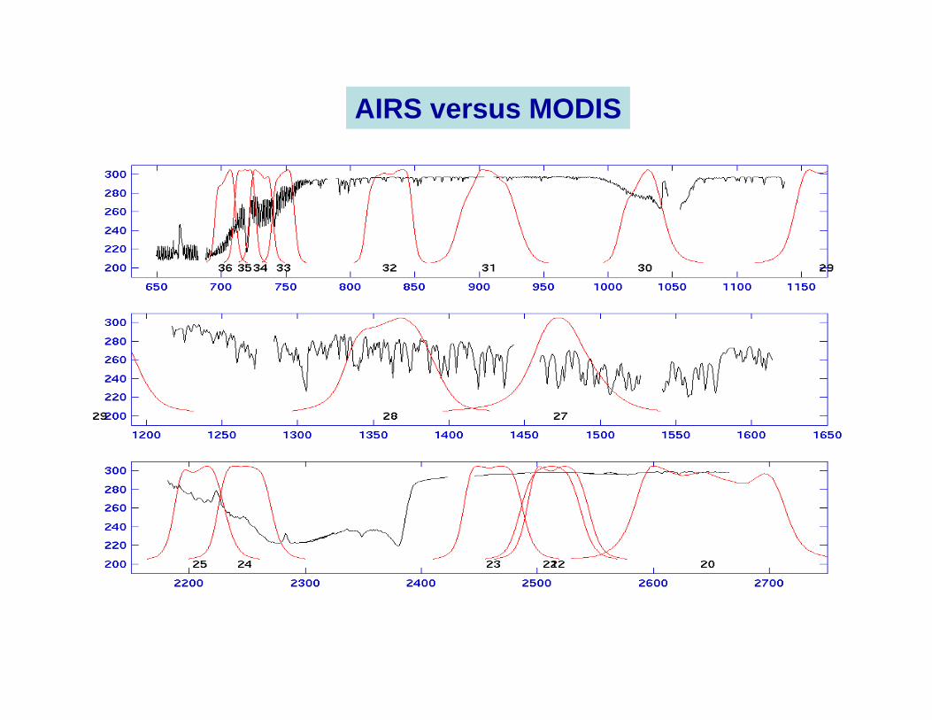
AIRS versus MODIS
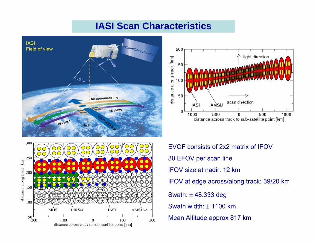
IASI Scan Characteristics
EVOF consists of 2x2 matrix of IFOV
30 EFOV per scan line
IFOV size at nadir: 12 km
IFOV at edge across/along track: 39/20 km
Swath: ± 48.333 deg
Swath width: ± 1100 km
Mean Altitude approx 817 km
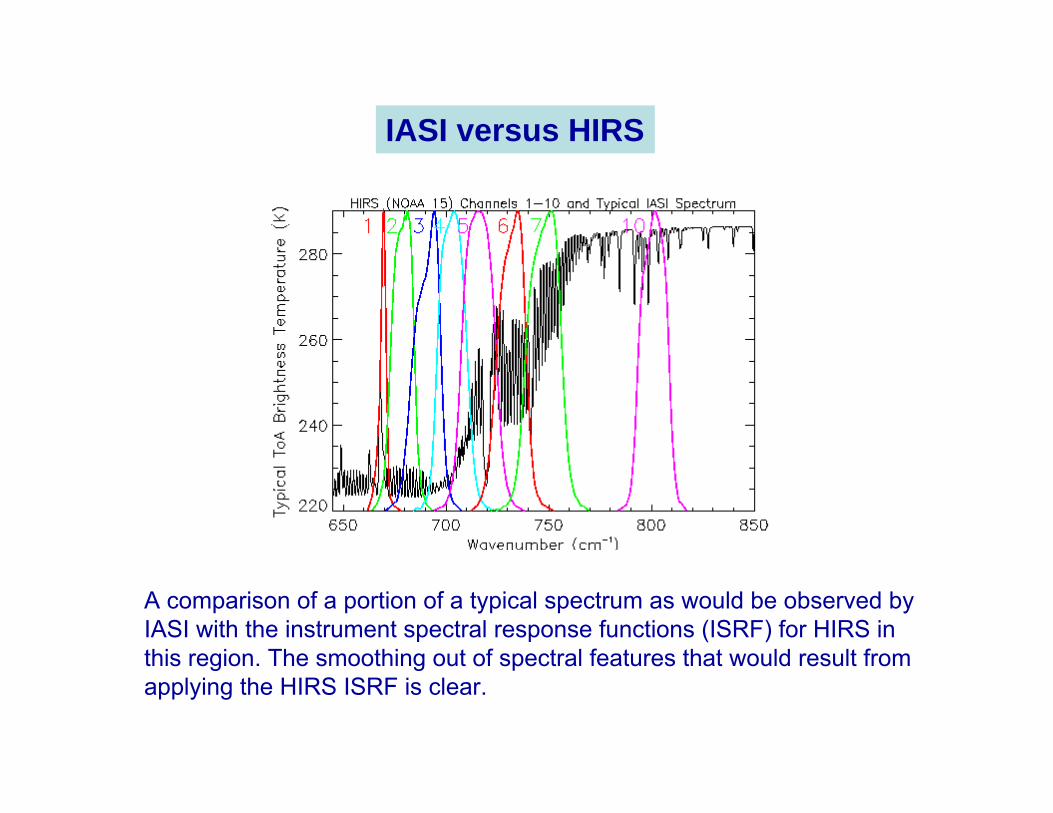
A comparison of a portion of a typical spectrum as would be observed by IASI with the instrument spectral response functions (ISRF) for HIRS in this region. The smoothing out of spectral features that would result from applying the HIRS ISRF is clear.
IASI versus HIRS
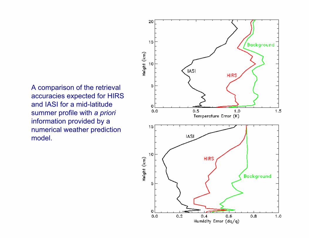
A comparison of the retrieval accuracies expected for HIRS and IASI for a mid-latitude summer profile with a prioriinformation provided by a numerical weather prediction model.
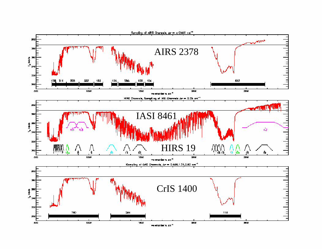
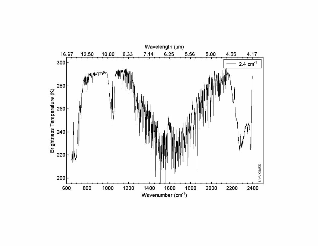
AIRS 2378
IASI 8461
CrIS 1400
HIRS 19
Spectral Absorption Features and Resolutions
Some examples
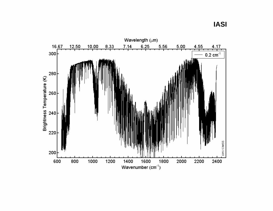
IASI
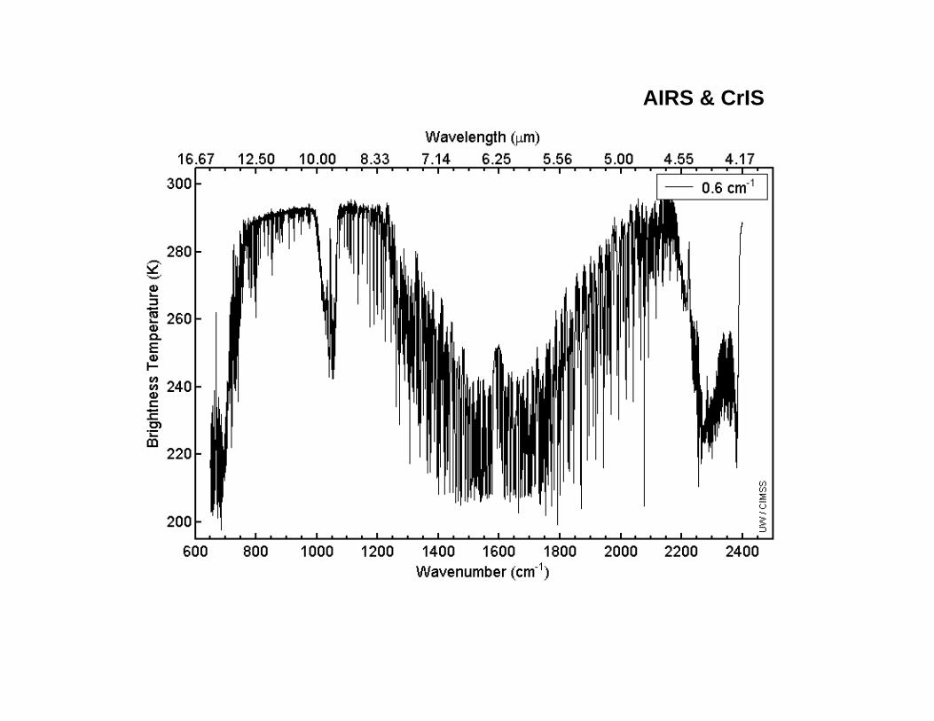
AIRS & CrIS
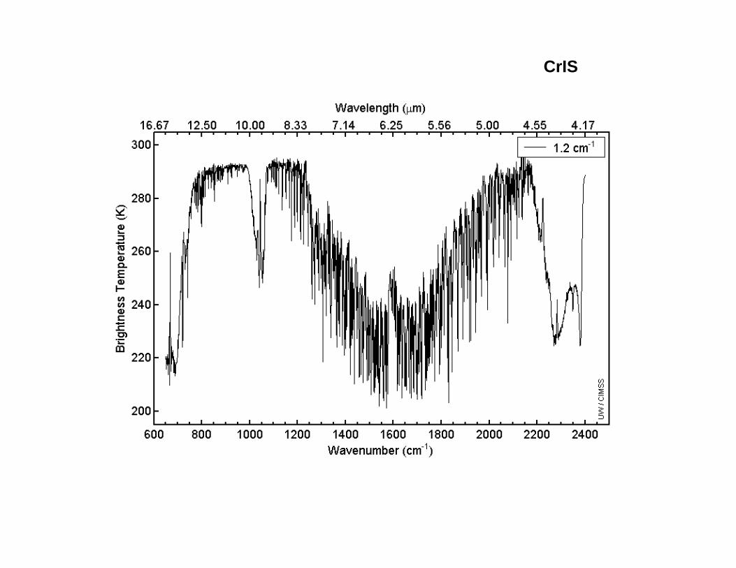
CrIS
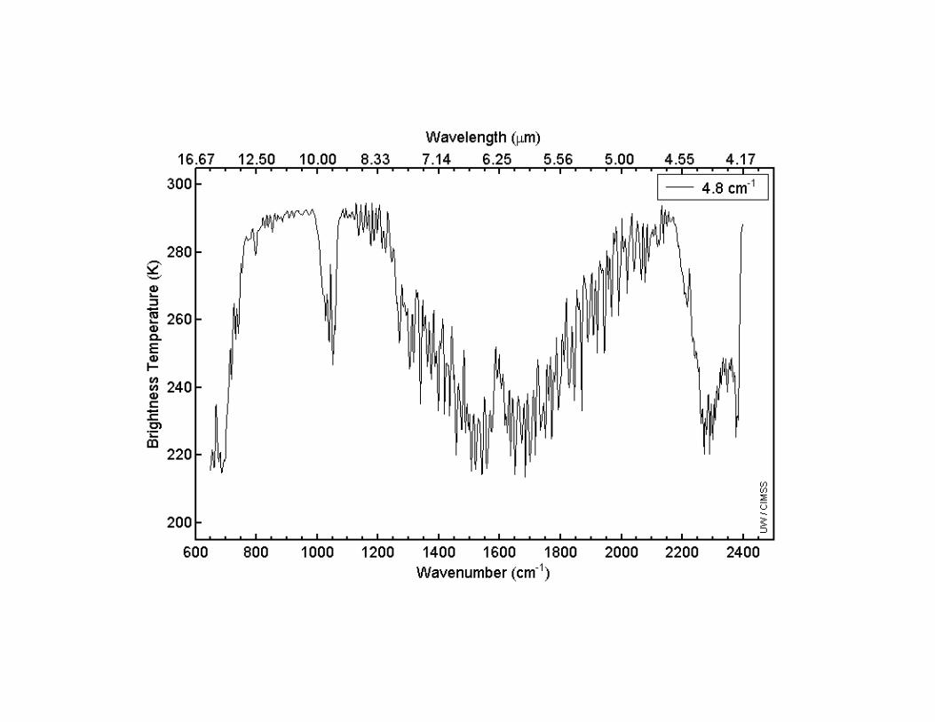
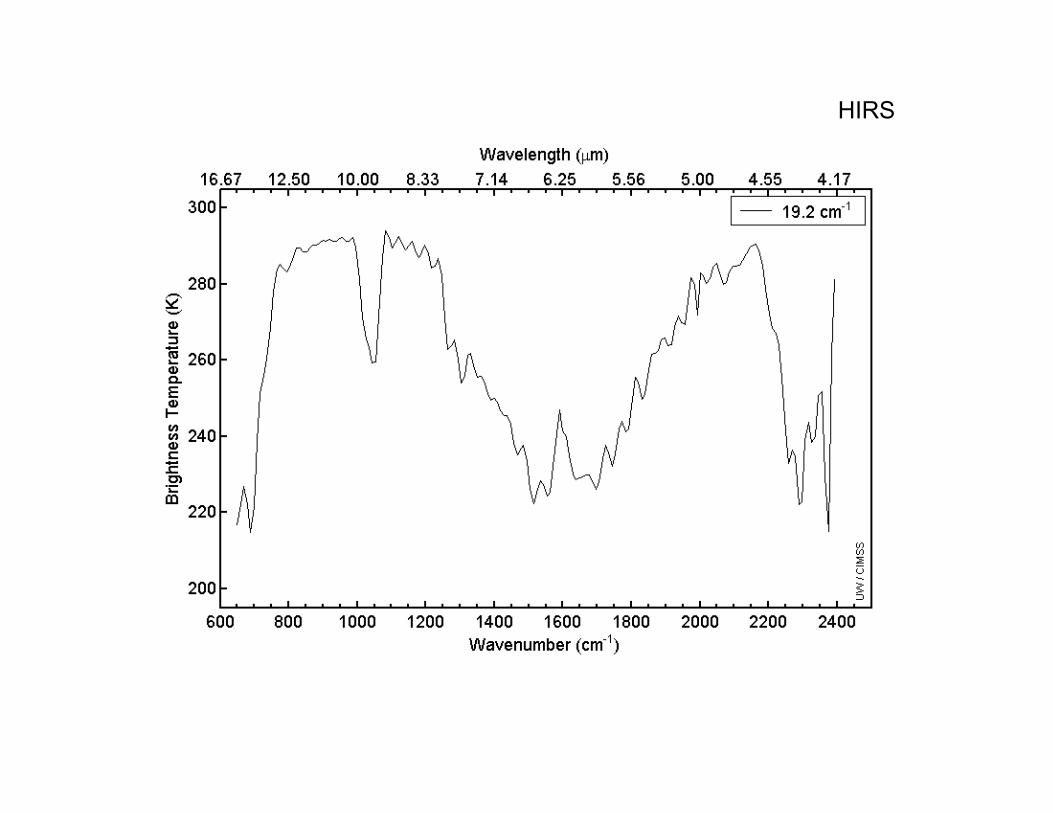
HIRS
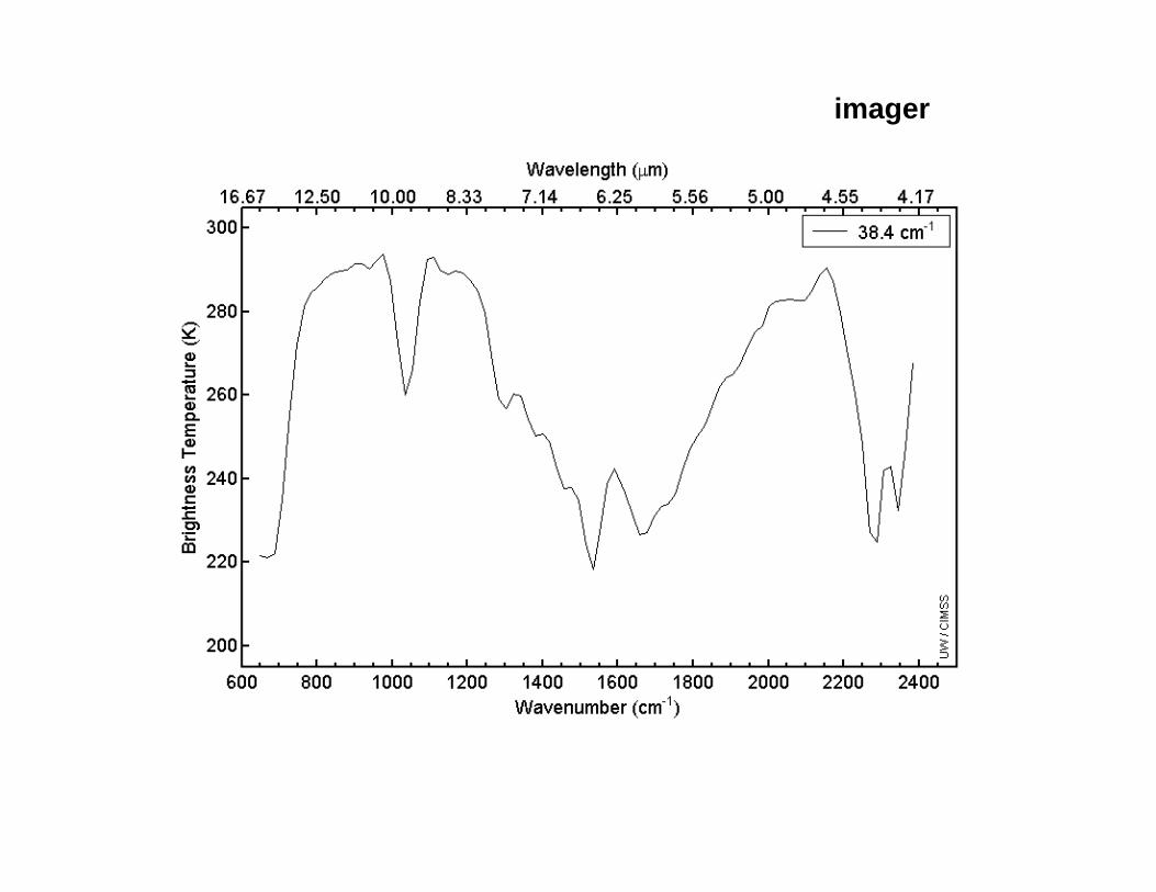
imager
Infrared Spectral Sounding Profile
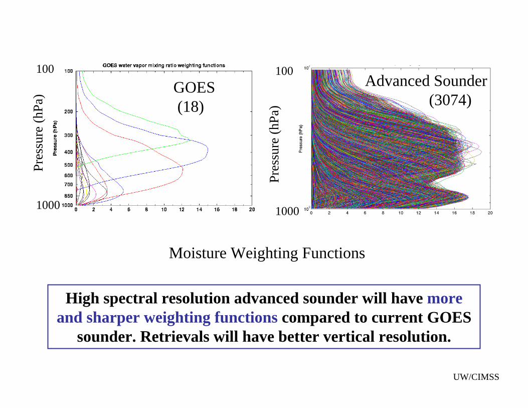
Moisture Weighting Functions
Pres
sure
(hPa
)
Pres
sure
(hPa
)
Advanced Sounder(3074)
GOES(18)
1000 1000
100 100
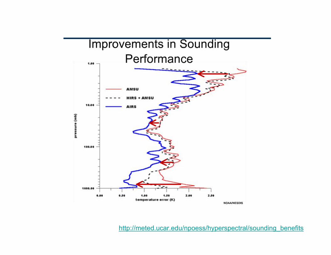
UW/CIMSS
High spectral resolution advanced sounder will have more and sharper weighting functions compared to current GOES
sounder. Retrievals will have better vertical resolution.
T
http://meted.ucar.edu/npoess/hyperspectral/sounding_benefits
http://meted.ucar.edu/npoess/hyperspectral/sounding_benefits
http://meted.ucar.edu/npoess/hyperspectral/sounding_benefits
http://meted.ucar.edu/npoess/hyperspectral/sounding_benefits
http://meted.ucar.edu/npoess/hyperspectral/sounding_benefits
http://meted.ucar.edu/npoess/hyperspectral/sounding_benefits
http://meted.ucar.edu/npoess/hyperspectral/sounding_benefits
http://meted.ucar.edu/npoess/hyperspectral/sounding_benefits
http://meted.ucar.edu/npoess/hyperspectral/sounding_benefits
COMET Module
"Advanced Satellite Sounding: The Benefits of the HyperspectralObservation". Lecture presented by Dr. Mitch Goldberg
http://meted.ucar.edu/npoess/hyperspectral/sounding_benefits
Next Generation Geostationary SatellitesThe next generation GOES will begin with GOES-R, which is currently scheduled to launch in the year 2015.
Next generation of low earth orbiting environmental satellitesThe National Polar-orbiting Operational Environmental Satellite System (NPOESS) is the next generation of low earth orbiting environmental satellites.
http://www.ipo.noaa.gov/index.php
Advanced infrared soundershttp://www.metoffice.gov.uk/research/nwp/satellite/infrared/sounders/index.html