model no....1999/01/16 · john deere lt tractor w l h figure 2 step 2: (see figure 2) • measure...
TRANSCRIPT

PRINTED IN U.S.A. FORM NO. 42363 rev. (2/6/14)
• Safety• Assembly• Operation• Maintenance• Parts
Model No.Modelo No.Modèle no
LBD48D
owNER'S MANUALMANUAL DE USUARIoNoTICE D’UTILISATIoN
CAUTION:ReadRulesforSafeOperationandInstructions
Carefully
PRECAUCIÓN:LeaCuidadosamentelasReglaseInstrucciones
deSeguridad
ATTENTION:Lireetsuivreattentivement
lesinstructionsetconsignesdesécurité
decettenotice.
the fastest way to purchase parts www.speedepart.com
™
48" SNow BLADECUCHILLA QUITANIEVE DE 48" (122 CM)
LAME CHASSE-NEIGE DE 48 Po. (122 CM)
• Seguridad• Armado• Operación• Mantenimiento• Piezas
• Sécurité• Assemblage• Utilisation• Entretien• PiècesdeRechange

2
TABLE oF CoNTENTS
SERVICEANDADJUSTMENTS .................................. 13STORAGE .................................................................... 13TROUBLESHOOTING .................................................. 13REPAIRPARTSILLUSTRATION ................................. 30REPAIRPARTSLIST .................................................... 31PARTSORDERING/SERVICE ..................BACKCOVER
Lookforthissymboltopointoutimportantsafetyprecautions.Itmeans—Attention!! Become alert!! Your safety is involved.
RULES FoR SAFE oPERATIoN
SAFETYRULES ............................................................. 2CARTONCONTENTS .................................................... 2FULLSIZEHARDWARECHART ................................... 3ASSEMBLY ..................................................................... 4OPERATION ..................................................................11MAINTENANCE ........................................................... 12
1. Readthetractorandsnowbladeowner'smanualsandknowhowtooperateyourtractorbeforeusingtractorwithsnowbladeattachment.
2. Neveroperatetractorandsnowbladewithoutwearingproperclothingsuitedtoweatherconditionsandoperationofcontrols.
3. Neverallowchildrentooperatetractorandsnowblade,anddonotallowadultstooperatewithoutproperinstructions.
4. Alwaysbeginwithtransmissioninfirst(low)gearandgraduallyincreasespeedasrequired.
Anypowerequipmentcancauseinjuryifoperatedimproperlyoriftheuserdoesnotunderstandhowtooperatetheequipment.Exercisecautionatalltimes,whenusingpowerequipment.
CARToN CoNTENTS
8
129
2
1
3
4 6
11
75
10
15
191614
1713
18
ENGLISH
REF QTY PART No. DESCRIPTIoN1 1 25122 LongHangerBracket2 1 25121 ShortHangerBracket3 1 25125 RearMountingBracket4 1 24023 PivotSupportBracket5 1 64732 ThrustChannel6 1 — ChannelAssembly7 1 — BladeAssembly8 1 46049 BladePivotRod9 1 65519 LiftHandleTube10 1 63033 LiftHandleRod
REF QTY PART No. DESCRIPTIoN11 2 25659 RearSupportChannel12 1 49808 Cable13 1 HA23380 RearLocatingBracket14 1 731-0869 GripAssembly15 1 R9466R BladeAdjustSpring16 2 23151 AngleLockBars17 2 25124 FrameBracket18 2 24690 SkidShoe19 1 46066 BladePivotShaft

3
SHowN FULL SIZE
HARDwARE PACKAGE
NoT SHowN FULL SIZE
ENGLISH
REF QTY PART No. DESCRIPTIoNA 1 46071 HexBolt,1/4-20x3-1/4"B 1 1509-90 HexBolt,1/4-20x1-1/4"C 4 43063 HexBolt,5/16-18x1"D 1 43085 HexBolt,5/16-18x1-1/2"E 4 710-0305 CarriageBolt,3/8-16x1-1/4"F 18 43350 CarriageBolt,3/8-16x1"G 3 47189 NylockNut,1/4-20H 9 47810 NylockNut,5/16-18I 24 HA21362 NylockNut,3/8-16J 2 712-0256 HexJamNut,5/16-24K 1 HA3980 ClevisPin,5/8"x1-3/4"L 2 44062 ClevisPin,1/2"x1"M 3 43343 HairpinCotter,LargeN 4 43055 HairpinCotter,SmallO 2 43010 CotterPin,1/8"x1-1/4"P 2 44917 Palnut,3/8"
REF QTY PART No. DESCRIPTIoNQ 4 43001 HexBolt,3/8-16x1"R 2 43003 LockWasher,3/8"S 3 R19171616 Washer,1/2"x1"T 1 23658 Spacer,9/16"x5/8"U 2 46053 Spacer,9/16"x1"V 2 44326 CarriageBolt,5/16-18x1"W 2 43080 CarriageBolt,5/16-18x3/4"X 2 47630 HexBolt,5/16-18x3/4"SelfThd.Y 4 43081 Washer,5/16"Z 4 R19172410 Washer,1/2"x1-1/2"AA 2 746-0260 CableEndFittingBB 1 05762 CableMountBracketCC 1 43348 AngleLockSpringDD 2 726-0178 NylonTieEE 1 23856 SpringMountRodFF 1 46065 ChannelPivotPin
I
J
H
G
A B
R
S
K
EDQ
M
N
O
P
C
F
L
T U
DD
EE FFCCBBAA
WV X
Z
Y
4
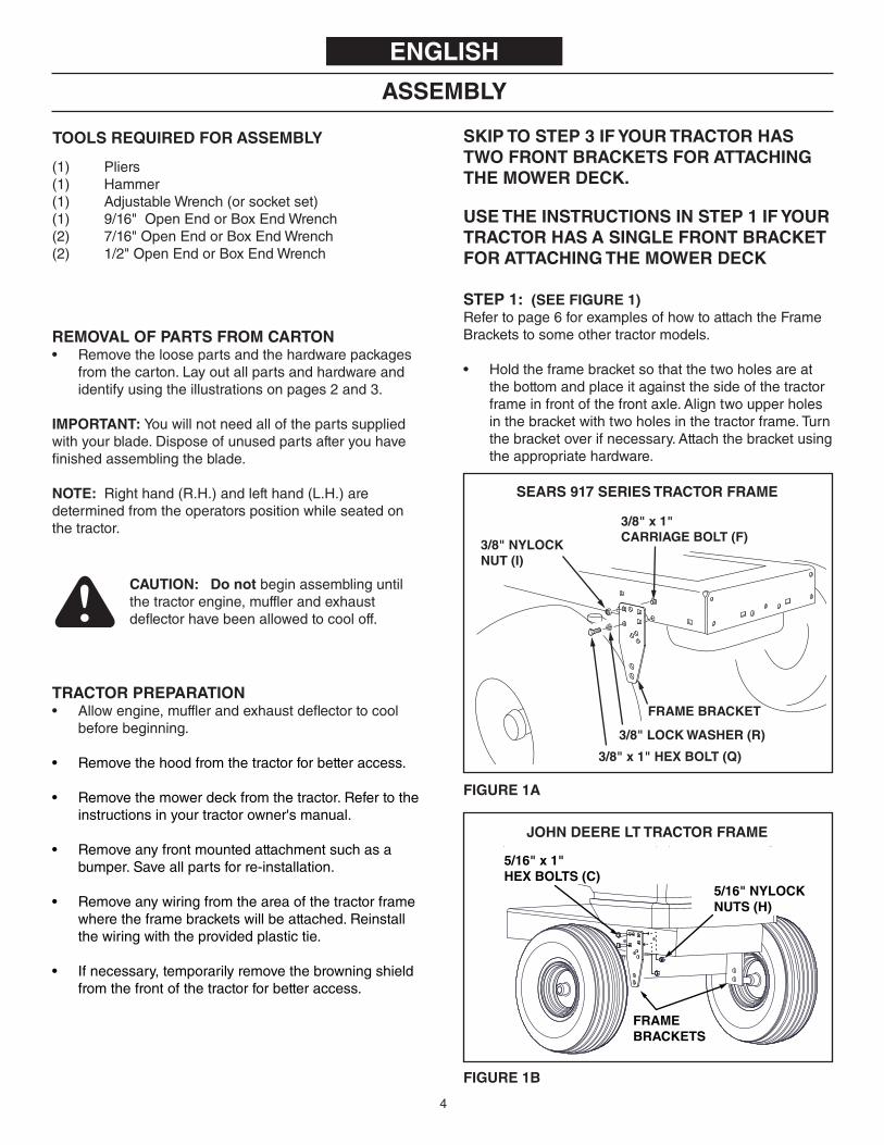
(1) Pliers(1) Hammer(1) AdjustableWrench(orsocketset)(1) 9/16"OpenEndorBoxEndWrench(2) 7/16"OpenEndorBoxEndWrench(2) 1/2"OpenEndorBoxEndWrench
TooLS REQUIRED FoR ASSEMBLY
REMoVAL oF PARTS FRoM CARToN• Removetheloosepartsandthehardwarepackages
fromthecarton.Layoutallpartsandhardwareandidentifyusingtheillustrationsonpages2and3.
IMPoRTANT: Youwillnotneedallofthepartssuppliedwithyourblade.Disposeofunusedpartsafteryouhavefinishedassemblingtheblade.
NoTE: Righthand(R.H.)andlefthand(L.H.)aredeterminedfromtheoperatorspositionwhileseatedonthetractor.
ENGLISH
CAUTIoN: Do notbeginassemblinguntilthetractorengine,mufflerandexhaustdeflectorhavebeenallowedtocooloff.
TRACToR PREPARATIoN• Allowengine,mufflerandexhaustdeflectortocool
beforebeginning.
• Removethehoodfromthetractorforbetteraccess.
• Removethemowerdeckfromthetractor.Refertotheinstructionsinyourtractorowner'smanual.
• Removeanyfrontmountedattachmentsuchasabumper.Saveallpartsforre-installation.
• Removeanywiringfromtheareaofthetractorframewheretheframebracketswillbeattached.Reinstallthewiringwiththeprovidedplastictie.
• Ifnecessary,temporarilyremovethebrowningshieldfromthefrontofthetractorforbetteraccess.
USE THE INSTRUCTIoNS IN STEP 1 IF YoUR TRACToR HAS A SINGLE FRoNT BRACKET FoR ATTACHING THE MowER DECK
STEP 1: (SEE FIGURE 1)Refertopage6forexamplesofhowtoattachtheFrameBracketstosomeothertractormodels.
• Holdtheframebracketsothatthetwoholesareatthebottomandplaceitagainstthesideofthetractorframeinfrontofthefrontaxle.Aligntwoupperholesinthebracketwithtwoholesinthetractorframe.Turnthebracketoverifnecessary.Attachthebracketusingtheappropriatehardware.
FIGURE 1B
FIGURE 1A
3/8" x 1" HEX BOLT (Q)
FRAME BRACKET
3/8" NYLOCKNUT (I)
3/8" x 1"CARRIAGE BOLT (F)
3/8" LOCK WASHER (R)
SEARS 917 SERIES TRACToR FRAME
JoHN DEERE LT TRACToR FRAME
FRAME BRACKETS
5/16" x 1"HEX BOLTS (C)
5/16" NYLOCKNUTS (H)
ASSEMBLY
SKIP To STEP 3 IF YoUR TRACToR HAS Two FRoNT BRACKETS FoR ATTACHING THE MowER DECK.

5
JOHN DEERE LT TRACTOR
W
L H
FIGURE 2
STEP 2: (SEE FIGURE 2)• MeasurethedistancesL,HandW.
L= distancefromcenteroflowerholesinframe brackettofrontoftractorframe. H= distancetocenterofholeinframebracketthatis closesttobeing6"abovegroundlevel. W=distancebetweentheinsideoftheframe brackets.
• Proceedtostep4.
FIGURE 3 - SEARS TRACToR SHowN
W
SEARS (LT) TRACTOR FRAME
H
DECK SUSPENSIONBRACKET
GROUND
L
STEP 3: (SEE FIGURE 3)• MeasurethedistancesL,HandW.
L= distancefromcenterofholeindecksuspension brackettofrontoftractorframe. H= distancefromcenterofholeindecksuspension brackettogroundlevel. W=insidedistancebetweenthedecksuspension brackets.
USE THESE INSTRUCTIoNS IF YoUR TRACToR HAS Two FRoNT BRACKETS FoR ATTACHING THE MowER DECK
ATTENTIoN:Gobacktostep1ifyourtractorhasonlyonefrontbracketforattachingthemowerdeck. 3/8" x 1-1/4"
CARRIAGE BOLT (E)
3/8" NYLOCK NUT (I)
LONG HANGER BRACKETSEnds down when "H" is 6" or lessEnds up when "H" is more than 6" W
L+
FRONT PLATE
FIGURE 4
STEP 4: (SEE FIGURE 4) Refertopage6forexamplesofhowtoattachtheHangerBracketstosomeothertractormodels.
• SelectthepairofslotsinthetopoftheThrustChannelthatwillprovideenoughclearancebetweenthebladeandthefrontofthetractorwhileminimizingoverhang. Selectthepairofslotsbasedondistance"L"measuredinstep2orstep3. L=5"orless Attachtothefrontpairofslots. L=5"to7" Attachtothemiddlepairofslots. L=7"to9" Attachtotherearpairofslots.
• ArrangetheHangerBracketswiththeshortHangerBracketontheinsideofthelongHangerBracketandplacethemontopoftheThrustChannel.Ifdistance"H",measuredinstep2or3,islessthan6",pointthebracketsdown.Ifdistance"H"ismorethan6",pointthebracketsup.
• AdjustthewidthoftheHangerBracketstojustslightlylessthandistance"W"measuredinstep2or3.CenterthebracketsontheThrustChannelandattachthemusingtwo3/8"x1-1/4"carriageboltsand3/8"nylocknuts.
• Tighten the nuts andthenmakesurethehangerbracketsfitbetweenthedecksuspensionbracketsorframebracektsonthetractor.
• Proceedtostep5onpage7.
USE THESE INSTRUCTIoNS FoR ALL TRACToRS

6
12.75"
3/8" x 1"HEX BOLT
3/8" x 1"CARRIAGEBOLT
LOCATE HANGER BRACKETS IN MIDDLE SET OF SLOTS IN THRUST CHANNEL
FRAMEBRACKET
SEARS 917 SERIES & HUSQVARNA TRACTORS WITHCENTER DECK SUSPENSION BRACKET AND 16" TIRES
SEARS 917 SERIES & HUSQVARNA LAWN TRACTORS
TRACTOR SUSPENSIONBRACKET
LOCATE HANGER BRACKETS IN MIDDLE SET OF SLOTS IN THRUST CHANNEL
9.75"
SEARS 917 SERIES & HUSQVARNA GARDEN TRACTORS
TRACTORSUSPENSIONBRACKET
LOCATE HANGER BRACKETS IN MIDDLE SET OF SLOTS IN THRUST CHANNEL
12"
13.00"
3/8" x 1"HEX BOLT
5/16" x 1"HEX BOLT
LOCATE HANGER BRACKETS IN MIDDLE SET OF SLOTS IN THRUST CHANNEL
FRAMEBRACKET
SEARS 247 SERIES LT 2000 &TROY-BILT PONY TRACTORS
FRAMEBRACKET
LOCATE HANGER BRACKETS IN FRONTSET OF SLOTS IN THRUST CHANNEL
5/16" x 3/4"HEX BOLT(self threading)
3/8" x 1"HEX BOLT
13"
SEARS MODEL 247.2898 PROFESSIONAL SERIES& MTD YARD TRACTORS & GARDEN TRACTORS
MTD - GARDEN TRACTORS
13"
TRACTORSUSPENSIONBRACKET
LOCATE HANGER BRACKETS IN FRONTSET OF SLOTS IN THRUST CHANNEL
MTD GARDEN TRACTORS
13"
TRACTORSUSPENSIONBRACKET
LOCATE HANGER BRACKETS IN FRONTSET OF SLOTS IN THRUST CHANNEL
MTD - LAWN TRACTORS
13"
TRACTORSUSPENSIONBRACKET
LOCATE HANGER BRACKETS IN FRONTSET OF SLOTS IN THRUST CHANNEL
MTD LAWN TRACTORS
13"
FRAMEBRACKET
LOCATE HANGER BRACKETS IN FRONTSET OF SLOTS IN THRUST CHANNEL
5/16" x 1"HEX BOLT
1/2" WASHER(LARGE)
12.75"
FRAMEBRACKET
3/8" x 1"CARRIAGEBOLT
5/16" x 3/4"HEX BOLT(self threading)
1/2" WASHER(LARGE)
LOCATE HANGER BRACKETS IN MIDDLE SET OF SLOTS IN THRUST CHANNEL
SEARS 917 SERIES & HUSQVARNA TRACTORS WITHCENTER DECK SUSPENSION BRACKET AND 15" TIRES

7
JOHN DEERE D100 SERIES TRACTORS
13"
FRAMEBRACKET
LOCATE HANGER BRACKETS IN FRONTSET OF SLOTS IN THRUST CHANNEL
5/16" x 1"HEX BOLT
JOHN DEERE LT
13"
FRAMEBRACKET
LOCATE HANGER BRACKETS IN FRONTSET OF SLOTS IN THRUST CHANNEL
5/16" x 1"HEX BOLT

8
STEP 9: (SEE FIGURE 9)• Assemblethepivotsupportbrackettothefrontofthe
ThrustChannelusingfour3/8"x1"carriageboltsandfour3/8"nylocknuts.Makesurethebracketisstraightandthentighten.
FIGURE 7 FIGURE 9
FIGURE 8
FIGURE 5
FIGURE 6
ENGLISHSTEP 5: (SEE FIGURE 5)• AttachtheRearLocatingBrackettothetopofthe
RearMountingBracketusingtwo3/8"x1"Carriageboltsand3/8"nylocknuts.Tightennuts.
• AttachtheRearSupportChannelstothemiddlesetofholesinthesidesoftheRearMountingBracketusingfour3/8"x1"CarriageBoltsand3/8"nylocknuts.Finger tighten only.
REAR SUPPORT CHANNELS
REAR MOUNTING BRACKET
REAR LOCATINGBRACKET
3/8" x 1"CARRIAGE BOLT (F)
3/8" NYLOCK NUT (I)
STEP 6: (SEE FIGURE 6)• SlidetheRearSupportChannelsundertherearof
thetractor.AttachtheRearMountingBrackettotheTractorDrawbarusingthe5/8"x1-3/4"ClevisPinandalargeHairpinCotter.
5/8" x 1-3/4"CLEVIS PIN (K)
LARGEHAIRPINCOTTER (M)
REARMOUNTINGBRACKET
REAR LOCATING BRACKET
REAR SUPPORT CHANNEL
STEP 7: (SEE FIGURE 7)• SlidetheThrustChannelunderthefrontofthetractor.
AttachtheHangerBracketstotheFrameBracketsorDeckSuspensionBracketsusingtwo1/2"x1"clevispins,1/2"washersandlargehairpincotters.
STEP 8: (SEE FIGURE 8)• PlacetheThrustChannelbetweenthetwoRear
SupportChannels.Installfour3/8"x1"carriageboltsand3/8"nylocknutsusingthemostwidelyspacedholesthatalignwithslots.Finger tighten only.
• IftheRearSupportChannelsbumpagainstthebottomofthetractor,reattachtherearofthechannelstoalowersetofholesintheRearMountingBracket.IfthereismoreclearancethannecessarybetweentheRearSupportChannelsandthebottomofthetractor,reattachtherearofthechannelstoahighersetofholesintheRearMountingBracket.
• Tightenallboltsandnutsinstalleduptothispoint.• MeasuretheheightofthefrontplateontheThrust
Channel.Ifitisnot4"to5"abovetheground,reinstalltheclevispinsintheHangerBracketstoahigherorlowerholepositiontoattainthecorrectheight.
THRUSTCHANNEL
1" x 1/2" CLEVIS PIN (L)
LARGE HAIRPINCOTTER (M)
1/2" WASHER (S)
REARSUPPORTCHANNELS
FRONT PLATE
3/8" x 1"CARRIAGE BOLT (F)
3/8" NYLOCKNUT (I)
4" to 5"
GROUND
3/8" x 1"CARRIAGE BOLT (F)
3/8" NYLOCKNUT (I)

9(Top View)FIGURE 11
FIGURE 12 (Right Hand Side View)
FIGURE 13 (Left Hand Side View)
(Right Hand Side View)FIGURE 10
ENGLISHSTEP 10: (SEE FIGURE 10)• Placethetwoanglelockbarstogethersothatallholes
arealigned.Assemblea3/8"x1-1/4"carriageboltanda3/8"nylocknutinthetophole.Besuretoinserttheboltfromthesideindicated. Finger tighten only.
• Inserttheroundhookendoftheanglelockspringupthroughtheholeinbracket(a).
• Holdtheanglelockbarssothatthesquareholesareatthetop.Insertthestraighthookendoftheanglelockspringthroughthemiddleholeinbothanglelockbars.
• Inserttheanglelockbarsdownthroughtheslotinthechannel.Underneaththechannel,placea1"longspaceroneachsideoftheanglelockbarsandinserta1/4"x3-1/4"boltthroughthechannel,theanglelockbarsandthespacers.Securetheboltwitha1/4"nylocknut.Tightensothatlockbarscanpivotfreely.
• Atthistimetightenthe3/8"carriageboltandnylonlocknutpreviouslyassembledtoanglelockbars.
NoTE: Whentheanglelockbarsarepulledback,thepivotplateshouldunlockandbefreetopivot.
STEP 11: (SEE FIGURE 11)• Useahammertotapa3/8"palnutontooneendofthe
springmountrod.Inserttherodthroughtherearsetofholesinthepivotplate.Supporttheassembledendofthespringmountrodonablockofwood,andtaptheremaining3/8"palnutontotheotherendoftherod.
STEP 12: (SEE FIGURE 12)• Assemblea3/8"x1-1/4"carriageboltthroughthesquare
holeinthecablemountbracketandthroughthesquareholeintheanglelockbarsasshown.(Thecarriageboltsshouldfaceinoppositedirections.)Usingpliersholdthecablemountbracketinposition,anglingdowntowardstheL.H.holeinthechannelasshown.Securewitha3/8"nylocknut. Tighten.Referalsotofigure14forthecorrectangleforthecablemountbracket.
STEP 13: (SEE FIGURE 13)• Selecttheendofthecontrolcablethathasnorubber
cap.Assembleone5/16"jamnutapproximately3/4"ontothethreadedendofthecontrolcable.Assemblethethreadedcableendthroughtheroundholeinthecablemountbracketasshownandsecurewithanother5/16"jamnut.Tighten.
NoTE: Someadjustmentofjamnutsmayberequiredafterbladeassemblyiscompleted.
1/4" x 3-1/4" HEX BOLT (A) 1" SPACERS (U)
1/4" NYLOCKNUT (G)
ANGLELOCKSPRING (CC)
(a)
3/8"x 1-1/4"CARRIAGE BOLT (E)
CHANNEL ANGLE LOCK BARS
3/8" NYLOCKNUT (I)
3/8" PALNUT (P)
PIVOT PLATE
SPRINGMOUNT
ROD (EE)
3/8" PALNUT (P)
3/8" x 1-1/4" CARRIAGE BOLT (E)
3/8" NYLOCKNUT (I)
ALIGN CABLEMOUNT BRACKET (BB)WITH L.H. HOLE
ANGLE LOCK BARS
FRONT
CHANNEL ASSEMBLY
5/16" JAM NUT (J)
5/16" JAM NUT (J)
CABLE MOUNT BRACKET
REAR
3/4"

10FIGURE 16 (Right Hand Side View)
FIGURE 14 (Left Hand Side View)
(Right Hand Side View) FIGURE 15
ENGLISH
STEP 14: (SEE FIGURE 14)• Assembleballendofcontrolcableupthroughholein
cableendfittingandpulluntilballslipsinsidecurlededgeoffittingasshown.Ifballwon'tslipunderedgeofcurlitwillneedtobeinsertedthroughopenendofcurl.
• Assemblea1/4"x1-1/4"hexboltdownthroughthecableendfitting,the5/8"longspacerandthelefthandholeinthechannelassembly.Securewitha1/4"nylocknut. Tighten.
NoTE: Makesurethecablemountbracketisalignedwiththecableendfittingasshowntopreventbindingofcable.Attachtheotherendofthecontrolcableinalaterstep.
STEP 15: (SEE FIGURE 15)• Toattachthebladetothechannelassembly,align
thenotchedholesinthepivotplatewiththenotchedholesintheblade.Inserta1/8"x1-1/4"cotterpindownthroughtheholeatthebendinthebladepivotshaft.Spreadtheendsofthepin.Fromtheleftsideinsertthebladepivotshaft,bendfacingup,throughthenotchedholes.Securetheshaftwithanother1/8"x1-1/4"cotterpinthroughtheendholeintheshaft.Spreadtheendsofthepin.
• Removetheplasticcapandone3/8"hexnutfromtheboltinthebladeadjustspring.Adjusttheremaining3/8"hexnutdownapproximately1"ontotheboltthreads.Hookthespringoverthespringmountrodasshown.Placetheboltupthroughtheholeinthetopedgeofthebladeandreassembletheother3/8"hexnutandtightendownagainstthetopedgeoftheblade.Replacetheplasticcapovertheendoftheboltthreads.
STEP 16: (SEE FIGURE 16)• Assemblethe1/2"washerontothechannelpivotpin.• Attachthechannelassemblytothetractorbyplacing
theendofthechannelassemblyupinsidethepivotsupportbracketonthetractor.Aligntheholeinthepivotsupportbracketwiththesecond hole inthechannelassembly.Insertthechannelpivotpinthroughthealignedholesfromtheleftsideandsecurewithasmallhairpincotterpushedallthewaythroughtotheloopend.
NoTE: Allhairpincottersonthissnowbladeshouldbe pushedthroughtotheirloopend.
1/4" x 1-1/4" HEX BOLT (B) CABLE END
FITTING
1/4" NYLOCK NUT (G)
5/8" SPACER (T)
CHANNEL ASSEMBLY
HOLE
REAR
3/8" HEX NUT (TOP)
PLASTIC CAP
3/8" HEX NUT (BOTTOM)
BLADE
1/8" x 1-1/4"COTTER PIN (O)
BLADE PIVOT SHAFT
SPRINGMOUNTROD (EE)
BLADE ADJUST SPRING
1/8" x 1-1/4"COTTERPIN (O)
PIVOT PLATE
1/2" WASHER (S)
CHANNEL PIVOT PIN (FF)
CHANNEL ASSEMBLY
HOLE IN END OF CHANNEL ASSEMBLY
SMALL HAIRPIN COTTER (N)
PIVOT SUPPORT BRACKET

11
ENGLISHSTEP 17: (SEE FIGURE 17)• Fromtheleftside,inserttheweldedendofthelift
handlerodthroughtheexposedholesintheendofthechannelassembly.Next,inserttheliftlinkpinthroughtheholeinthebracketthatisweldedtothelifthandlerod.(Theliftlinkispre-assembledtothepivotsupportbracket).Securethebracketwithasmallhairpincotter.
• Applyalightcoatingofoiltothestraightupperportionofthelifthandlerod.Slidethelifthandletubeontotherod.
LIFT HANDLE ROD
HAIRPIN COTTER (N)
LONG PIN (LIFT LINK)
WELDED BRACKET
LIFT HANDLE TUBE
5/16" x 1"CARRIAGE BOLT (F)
5/16" x 3/4"CARRIAGE BOLT (W)
5/16" WASHER (Y)
5/16" NYLOCK NUT (H)
SKID SHOE
STEP 18: (SEE FIGURE 18)• Pivotthebladetothecenterpositionandloweritto
theground.Placeshimsunderthebladetocreatetheamountofgroundclearanceyouwant.Themoreuneventhesurfacethemoreclearanceyouwillneed.
• Attachtheskidshoestothebladeusinga5/16"x3/4"carriageboltinthetopholeanda5/16"x1"carriageboltinthebottomhole.Withtheskidshoesrestingontheground,securetheboltswith5/16"washersand5/16"nylocknuts.
FIGURE 18 (Left Hand Side View)
FIGURE 19 (Right Hand Side View)
FIGURE 20 (Right Hand Side View)
CABLE ENDFITTING (AA)
STEP 19: (SEE FIGURE 19)• Removetherubbercapandthefirstjamnutfromthe
threadedendofthecontrolcableandslidethemontothecontrolcablewire.Adjustthesecondjamnutonthethreadssothatitisapproximately3/4"fromend.Assemblethreadedendofcablethroughthecablemountbracketonthelifthandletubeandsecureitwiththefirstjamnut.Reinstalltherubbercapontothethreadedcableend.
NoTE: Someadjustmentofjamnutsmayberequired afterbladeassemblyiscompleted.
STEP 20: (SEE FIGURE 20)• Assembletheplasticgripontothegripassembly.• Attachthegripassemblytothelifthandletubeusing
one5/16"x1-1/2"hexboltandone5/16"nylocknut.Donotovertightenthenylocknut.Thegripassemblymustpivotfreely.
• Assembletheballendofthecabletoacableendfittingaswasdonetotheotherendofthecable.Securethecableendfittingtotheweldboltonthelockreleasegripwitha1/4"nylocknut.Donotovertightenthenylocknut.Thecablefittingmustpivotfreely.
RUBBERCAP
CABLE MOUNT BRACKET
JAM NUTS
3/4"CONTROL CABLE END
5/16" x 1-1/2" HEX BOLT (D)
PLASTICGRIP
1/4" WELD BOLT
CABLE ENDFITTING (AA)
5/16" NYLOCKNUT (H)
1/4 " NYLOCKNUT (G)
CABLE
GRIPASSEMBLY
FIGURE 17 (Left Hand Side View)

12
FIGURE 21 (Left Hand Side View)
ENGLISHSTEP 21: (SEE FIGURE 21)• Placethelongendofthebladepivotroddown
throughthebladepivotshaft.Attachtheshortendofthebladepivotrodtothelifthandletube.Securebothendswithsmallhairpincotters.
• Usethetwoplastictiestoholdthecablesecurelytotheoutsideofthehandletubeandawayfromthetractortoavoiddirectheatfromthetractormuffler.
BLADE PIVOT ROD LIFT HANDLE
TUBE
SMALL HAIRPINCOTTER (N)
SMALL HAIRPIN COTTER (N)
PLASTIC TIES (DD)
BLADE PIVOT SHAFT
13
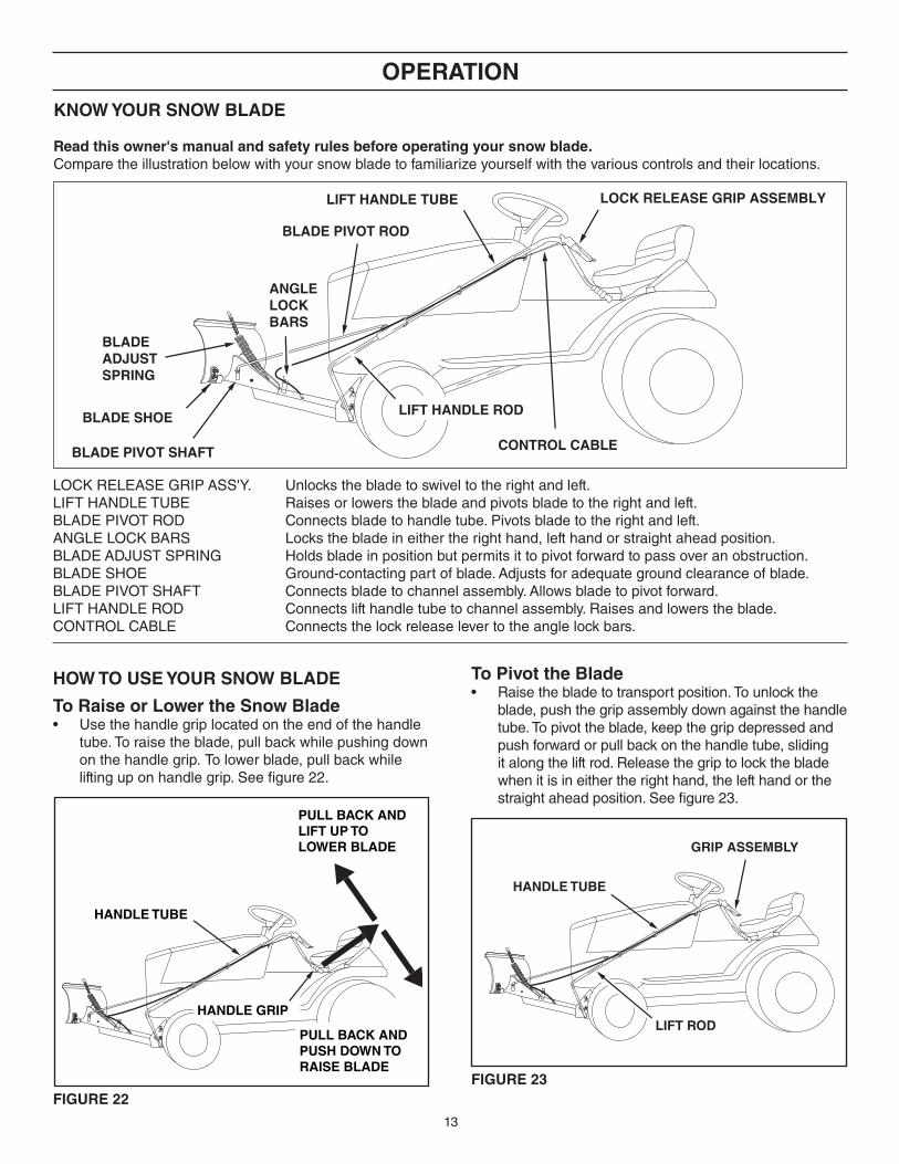
FIGURE 22FIGURE 23
To Raise or Lower the Snow Blade• Usethehandlegriplocatedontheendofthehandle
tube.Toraisetheblade,pullbackwhilepushingdownonthehandlegrip. Tolowerblade,pullbackwhileliftinguponhandlegrip.Seefigure22.
oPERATIoN
How To USE YoUR SNow BLADE To Pivot the Blade• Raisethebladetotransportposition.Tounlockthe
blade,pushthegripassemblydownagainstthehandletube.Topivottheblade,keepthegripdepressedandpushforwardorpullbackonthehandletube,slidingitalongtheliftrod.Releasethegriptolockthebladewhenitisineithertherighthand,thelefthandorthestraightaheadposition.Seefigure23.
KNow YoUR SNow BLADE
Read this owner's manual and safety rules before operating your snow blade.Comparetheillustrationbelowwithyoursnowbladetofamiliarizeyourselfwiththevariouscontrolsandtheirlocations.
LOCKRELEASEGRIPASS'Y. Unlocksthebladetoswiveltotherightandleft.LIFTHANDLETUBE Raisesorlowersthebladeandpivotsbladetotherightandleft.BLADEPIVOTROD Connectsbladetohandletube.Pivotsbladetotherightandleft.ANGLELOCKBARS Locksthebladeineithertherighthand,lefthandorstraightaheadposition.BLADEADJUSTSPRING Holdsbladeinpositionbutpermitsittopivotforwardtopassoveranobstruction.BLADESHOE Ground-contactingpartofblade.Adjustsforadequategroundclearanceofblade.BLADEPIVOTSHAFT Connectsbladetochannelassembly.Allowsbladetopivotforward.LIFTHANDLEROD Connectslifthandletubetochannelassembly.Raisesandlowerstheblade.CONTROLCABLE Connectsthelockreleaselevertotheanglelockbars.
BLADE SHOE
BLADE PIVOT SHAFT
LIFT HANDLE TUBE
BLADE PIVOT ROD
BLADEADJUSTSPRING
ANGLELOCKBARS
LOCK RELEASE GRIP ASSEMBLY
CONTROL CABLE
LIFT HANDLE ROD
HANDLE TUBE
PULL BACK AND LIFT UP TOLOWER BLADE
PULL BACK ANDPUSH DOWN TO RAISE BLADE
HANDLE GRIP
HANDLE TUBE
GRIP ASSEMBLY
LIFT ROD

14
wheel weights and tire chains must be used with your snow blade for traction. These accessories are available at your nearest Sears retail store.
Using the Snow Blade• Preparethelawntractorengineforcoldweather
usinginstructionsfurnishedwiththelawntractor.
• Alwaysbeginwiththetransmissioninfirst(low)gearandgraduallyincreasespeedasrequired.
• Do notrepeatedlypushsnowinthesamedirection,causingexcessivebuildupwitheachsuccessivepass.
• Toreduceicingontheblade,allowthelawntractorandbladetoadjusttooutdoortemperaturebeforeoperating.
• Forimprovedsnowremovalperformance,coatthebladewithautomotivetypepastewax.
CAUTIoN: Inspectcarefullytheareatobeworkedbeforeoperatingthesnowblade.Avoidpipes,roots,curbsorotherheavyobstructions.
CAUTIoN: Knowtheterrain.Avoidexceptionallysteepslopesordropoffswhichmaybehiddenbythesnow.Neverrunthesnowbladeintoheavymaterialathighspeed.
CAUTIoN: Alwayslowerthebladetothegroundbeforeleavingthetractor.
MAINTENANCESCHEDULE Fillindatesasyou completeregularservice. Be
foree
achu
se
Aftereachus
e
ServiceDates
CUSToMER RESPoNSIBILITIES
• Readandfollowthemaintenancescheduleandtheprocedureslistedinthemaintenancesection.
Every
season
Befores
torage
• Duringtheoperatingseason,checkallbolts,nutsandhairpincotterstobesuretheyaresecure.
Lubrication Points• Lubricateallpivotpointstohelpmaintainproper
operationofblade.Applyalightcoatingofgreasetothestraightupperportionofthelifthandlerod.Seefigure24.
Checkforloosefasteners X Checkforwornordamagedparts X CleanBlade X X LubricateBlade X
FIGURE 24
MAINTENANCE
LUBRICATELUBRICATE
LUBRICATE

15
To Adjust Blade Spring• Thetensionofthebladeadjustspringmaybealtered
topermitthebladetotiltforwardtobypasssolidobstructions.Tochangethespringtension,adjustthenutsatupperendofthespringbolt.Turnthenutscounterclockwisetorelievetensionandclockwisetoincreasetension.Refertofigure15onpage10.
To Adjust Blade Shoes• Thebladeshoesattheendsofblademayberaised
forcloseworkonsmoothsurfacesorloweredtoraisethebladetoworkonroughorunevenareas.Makesurebothshoesaresetevenlyandthatthenutsaretightenedsecurely.Seefigure25.
SERVICE AND ADJUSTMENTS
FIGURE 25
To Adjust the Blade Pivot Lock Mechanism• Ifthebladewillnotunlockandpivot,theanglelock
barsarenotdisengagingfromtheslotsinthepivotplate.Tocorrect,adjustthe5/16"hexjamnutstodrawtheendofthecontrolcablebacktowardsthecablemountbracket.Thelessthethreadedendofthecableextendsthroughthebracket,themoretheanglelockbarscanretracttodisengagefromtheslotsinthepivotplate.Seefigure26.
FIGURE 26
Recommendations when Storing• Whenthesnowbladeisnotbeingused,removeall
dirtandrustandtouchupwithpaint.• Touchupbaremetalwithpaintorapplyalightcoatof
greaseorrustpreventive.• Lubricateallpivotpointsandallpointsshownin
figure24,page14inthemaintenancesection.• Storeinadryarea,protectedfromweather.
SToRAGE
TRoUBLESHooTING
CABLE MOUNT BRACKET
5/16" HEXJAM NUT
CONTROL CABLE
5/16" HEX JAM NUT
BLADE SHOE
To Remove Blade From Tractor• Lowerthebladeheadtothegroundwiththebladein
thecenter(straightahead)position.• Removethetwoclevispinswhichfastentheblade's
hangerbracketstothetractor'smowerdecksuspensionbrackets(orframebrackets).Seefigure7onpage8.
• Removetheclevispinthatfastenstheblade'srearmountingbrackettothetractor'sdrawbaranddroptherearofthebladeframetotheground.Seefigure6onpage8.
• Removetheframebrackets(ifused).Seefigure1onpage4.
• Backthetractoroffofthebladeassembly.
PRoBLEM CAUSE CoRRECTIoNBladeisdifficulttoraise. Liftmechanismisbinding. Lubricatepivotpointsasshownin
figure23onpage14.
Bladeisdifficulttopivot. Handletubeisbindingonliftrod. Lubricatelifthandlerodasinstructedonpage14.
Bladewillnotunlocktopivot. Lockmechanismisoutofadjustmentandisnotdisengaging.
RefertotheServiceandAdjustmentssectiononpage15.

16
ÍNDICE
SERVICIOYAJUSTES........................................................... 21ALMACENAMIENTO .............................................................. 21RESOLUCIONDEPROBLEMAS .......................................... 21DIAGRAMADEPIEZASDEREPUESTO .............................. 30LISTADEPIEZASDEREPUESTO ........................................ 31SERVICIODEORDENESDEPIEZAS ...... CONTRAPORTADA
EsteSímboloIndicaPrecaucionesImportantesDeSeguridad.Significa—¡Atención! ¡Esté Alerta! Su Seguridad Está En Riesgo
REGLAS DE SEGURIDAD
REGLASDESEGURIDAD ..................................................... 14CONTENIDODELCARTÓN .................................................. 14CUADRODEFERRETERÍA-TAMAÑOREAL ....................... 15ARMADO ........................................................................... 16-19OPERACIÓN ..................................................................... 19-20MANTENIMIENTO.................................................................. 20
1. Lea losmanualesdel usuariodel tractor deprado yde lacuchilladeremocióndenieveyconozcabiencomoseoperasutractorantesdeusarloconlacuchilla.
2. Nuncaopereeltractorylacuchillasinlaropaapropiadadeacuerdoconlascondicionesdeltiempoylaoperacióndeloscontroles.
3. Nopermitanuncaquelosniñosopereneltractorylacuchilla,ynodejequeningúnadultolosoperesinconoceranteslasrespectivasinstrucciones.
4. Empiecesiempreconlatransmisiónenprimeravelocidad(baja)yconelmotorabajavelocidad,ygradualmenteaumentelavelocidadsegúnlopermitanlascondiciones.
Todoequipomecanizadopuedecausardañossisemanejainadecuadamenteosielusuarionoconoceelfuncionamientodelequipo.Manténgaseatentoycautelososiemprequeopereelequipo.
CoNTENIDo DE LA CAJA
REF. CANT. PARTE No
DESCRIPCIoN
1 1 25122 MénsuladeColgarLarga2 1 25121 MénsuladeColgarCorta3 1 25125 MénsuladeMontajeTrasero4 1 24023 MénsuladeSoportedeGiro5 1 64732 VigadeCanaldeEmpuje6 1 — ConjuntodeCanal7 1 — ConjuntodeCuchilla8 1 46049 BarradeGirodeCuchilla9 1 65519 TubodeManejodeLevante10 1 63033 BarradeManejodeLevante
REF. CANT. PARTE No
DESCRIPCIoN
11 2 25659 VigadeCanaldeSoporteTrasero12 1 49808 Cable13 1 HA23380 MénsuladeUbicaciónTrasera14 1 731-0869 ConjuntodeAberturadeCierre15 1 R9466R ResortedeAjustedeCuchilla16 2 23151 BarrasdeCierredeAngulo17 2 25124 MénsuladeMarco18 1 24690 ZapatadePatíndeLaCuchilla19 2 46066 EjedeGirodelaCuchilla
8
129
2
1
3
4 6
11
75
10
15
191614
1713
18
ESPAÑoL
17
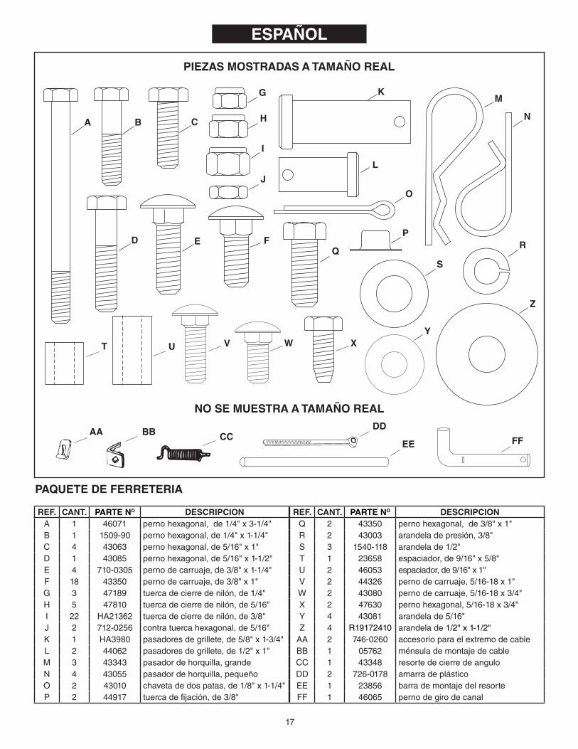
PIEZAS MoSTRADAS A TAMAÑo REAL
REF. CANT. PARTE No DESCRIPCIoNA 1 46071 pernohexagonal,de1/4"x3-1/4"B 1 1509-90 pernohexagonal,de1/4"x1-1/4"C 4 43063 pernohexagonal,de5/16"x1"D 1 43085 pernohexagonal,de5/16"x1-1/2"E 4 710-0305 pernodecarruaje,de3/8"x1-1/4"F 18 43350 pernodecarruaje,de3/8"x1"G 3 47189 tuercadecierredenilón,de1/4"H 5 47810 tuercadecierredenilón,de5/16"I 22 HA21362 tuercadecierredenilón,de3/8"J 2 712-0256 contratuercahexagonal,de5/16"K 1 HA3980 pasadoresdegrillete,de5/8"x1-3/4"L 2 44062 pasadoresdegrillete,de1/2"x1"M 3 43343 pasadordehorquilla,grandeN 4 43055 pasadordehorquilla,pequeñoO 2 43010 chavetadedospatas,de1/8"x1-1/4"P 2 44917 tuercadefijación,de3/8"
REF. CANT. PARTE No DESCRIPCIoNQ 2 43350 pernohexagonal,de3/8"x1"R 2 43003 arandeladepresión,3/8"S 3 1540-118 arandelade1/2"T 1 23658 espaciador,de9/16"x5/8"U 2 46053 espaciador,de9/16"x1"V 2 44326 pernodecarruaje,5/16-18x1"W 2 43080 pernodecarruaje,5/16-18x3/4"X 2 47630 pernohexagonal,5/16-18x3/4"Y 4 43081 arandelade5/16"Z 4 R19172410 arandelade1/2"x1-1/2"AA 2 746-0260 accesorioparaelextremodecableBB 1 05762 ménsulademontajedecableCC 1 43348 resortedecierredeanguloDD 2 726-0178 amarradeplásticoEE 1 23856 barrademontajedelresorteFF 1 46065 pernodegirodecanal
PAQUETE DE FERRETERIA
No SE MUESTRA A TAMAÑo REAL
ESPAÑoL
I
J
H
G
A B
R
S
K
EDQ
M
N
O
P
C
F
L
T U
DD
EE FFCCBBAA
WV X
Z
Y

18
ADAPTACIoNES PARA DIVERSoS TRACToRES
TRACTORES DE PRADOSEARS DE LA SERIE 917
MÉNSULA DE SUSPENSIÓN DEL TRACTOR
COLOQUE LAS MÉNSULAS DE COLGAR EN EL JUEGO DE RANURAS INTERMEDIAS EN LA VIGA DE CANAL DE EMPUJE
9,75" (25 CM)
TRACTORES DE JARDÍNSEARS DE LA SERIE 917
12,00" (30 CM) MÉNSULA DE
SUSPENSIÓN DEL TRACTOR
COLOQUE LAS MÉNSULAS DE COLGAR EN EL JUEGO DE RANURAS INTERMEDIAS EN LA VIGA DE CANAL DE EMPUJE
TRACTORES PRADO DE MTD DE ENGANCHE RÁPIDO
MÉNSULA DE SUSPENSIÓN DEL TRACTOR
COLOQUE LAS MÉNSULAS DE COLGAR EN EL JUEGO DE RANURAS DEL FRENTE EN LA VIGA DE CANAL DE EMPUJE
TRACTORES DE JARDÍN DE MTD DE ENGANCHE RÁPIDO
13,00" (33 CM)
MÉNSULA DE SUSPENSIÓN DEL TRACTOR
TRACTORESDE JARDÍN MTD
13,00" (33 CM)
MÉNSULA DE SUSPENSIÓN DEL TRACTOR
COLOQUE LAS MÉNSULAS DE COLGAR EN EL JUEGO DE RANURAS DEL FRENTE EN LA VIGA DE CANAL DE EMPUJE
TRACTORES DE PRADO MTD
MÉNSULA DE MARCO
COLOQUE LAS MÉNSULAS DE COLGAR EN EL JUEGO DERANURAS DEL FRENTE EN LA VIGA DE CANAL DE EMPUJE
PERNO DEHEXAGONALDE 5/16" x 1"
PERNOHEXAGONALDE 3/8" x 1"
PERNO DE CARRUAJE DE 3/8" x 1"
COLOQUE LAS MÉNSULAS DE COLGAR EN EL JUEGO DERANURAS DEL FRENTE EN LA VIGA DE CANAL DE EMPUJE
MÉNSULA DE MARCO
TRACTORES SEARS DE LA SERIE 917 CON MÉNSULA DE SUSPENSION CENTRAL (16" NEUMÁTICOS)
COLOQUE LAS MÉNSULAS DE COLGAR EN EL JUEGO DERANURAS DEL FRENTE EN LA VIGA DE CANAL DE EMPUJE
13,00" (33 CM)
13,00" (33 CM)
12,75"(32 cm)
ARANDELA1/2" x 1-1/4"
PERNOHEXAGONALDE 5/16" x 3/4"
PERNO DE CARRUAJE DE 3/8" x 1"
COLOQUE LAS MÉNSULAS DE COLGAR EN EL JUEGO DERANURAS DEL FRENTE EN LA VIGA DE CANAL DE EMPUJE
MÉNSULA DE MARCO
TRACTORES SEARS DE LA SERIE 917 CON MÉNSULA DE SUSPENSION CENTRAL (15" NEUMÁTICOS)
12,75"(32 cm)
ARANDELA1/2" x 1-1/4"
13,00"(33 cm)
PERNOHEXAGONALDE 5/16" x 1"
TRACTORES SEARS DE LA SERIE 247 LT 2000 YTROY-BILT PONY TRACTORES
MÉNSULA DE MARCO
COLOQUE LAS MÉNSULAS DE COLGAR EN EL JUEGO DE RANURAS INTERMEDIAS EN LA VIGA DE CANAL DE EMPUJE
PERNOHEXAGONALDE 3/8" x 1"
13,00"(33 cm) MÉNSULA
DE MARCO
PERNOHEXAGONALDE 5/16" x 3/4"COLOQUE LAS MÉNSULAS DE COLGAR EN EL JUEGO DE
RANURAS DEL FRENTE EN LA VIGA DE CANAL DE EMPUJE
SEARS MODELO PROFESIONAL 247,2898 TRACTORESy MTD YARD TRACTORES y TRACTORES DE JARDÍN
PERNOHEXAGONALDE 3/8" x 1"

19
TRACTORES JOHN DEERE LT
13,00" (33 CM)
MÉNSULA DE MARCO
COLOQUE LAS MÉNSULAS DE COLGAR EN EL JUEGO DERANURAS DEL FRENTE EN LA VIGA DE CANAL DE EMPUJE
PERNO DEHEXAGONALDE 5/16" x 1"
TRACTORES JOHN DEERE DE LA SERIE D100
PERNO DEHEXAGONALDE 5/16" x 1"
MÉNSULA DE MARCO
COLOQUE LAS MÉNSULAS DE COLGAR EN EL JUEGO DERANURAS DEL FRENTE EN LA VIGA DE CANAL DE EMPUJE
13,00" (33 CM)
ADAPTACIoNES PARA DIVERSoS TRACToRES

20
(1) alicates(1) martillo (1) llaveajustable(ojuegodellavesdecopa)(1) llavede9/16"deextremoabiertoodecaja(2) llavesde7/16"deextremoabiertoodecaja(2) llavesde1/2"deextremoabiertoodecaja
HERRAMIENTAS NECESARIAS PARA EL ARMADo
REMoCIÓN DE LAS PIEZAS DE LA CAJA
• Remuevalaspiezassueltasylospaquetesdeferreteríadelcartón.Dispongalaspiezasylaferretería,identificándolascomosemuestraenlosdiagramasdelaspáginas14y15.
IMPoRTANTE: Nonecesitarátodaslaspiezasqueseincluyenconlacuchilla.Dispongadelaspartesnousadasunavezquehayaterminadoelarmadodelacuchilla.
NoTA: LaManoDerechaylaManoIzquierdasedeterminandesdeelpuntodevistadeloperadorsentadoeneltractor.
PRECAUCIÓN: No principieelarmadohastaantesdequeeltuboyeldeflectordeescapesehayanenfriado
PASo 2: (VEA LA FIGURA 2)• Midalasdistancias,largo,altoyancho.
Largo=distanciadesdeelcentrodelosagujerosinferioresdelaménsulademarcodeltractorhastaelfrentedelmarcodeltractor. Alto=distanciaalcentrodelagujerodelaménsulademarcoqueestámáscercaa6"(15cm)delniveldelsuelo. Ancho=distanciaentrelosladosinterioresdelasménsulasdemarcodeltractor.
• Prosigaalpaso4.
VAYA AL PASo 3 SI SU TRACToR TIENE DoS MÉNSULAS DELANTERAS PARA ACoPLAR EL MUELLE DE LA CoRTA-DoRA DE CÉSPED.
USE LAS INSTRUCCIoNES DEL PASo 1 SI SU TRACToR TIENE SÓLo UNA MÉNSULA DELANTERA PARA ACoPLAR EL MUELLE DE LA CoRTADoRA DE CÉSPED.
PASo 1: (VEA LA FIGURA 1)Consultelapágina6paraverejemplosdecómoacoplarlasménsulasdemarcoparaalgunosotrosmodelosdetractores.
• Sujetelaménsuladelmarcodemaneraquelosdosagujerosesténabajoycolóquelacontraelladodelmarcodeltractorqueestáalfrentedelejedelantero.Alineelosdosagujerossuperioresdelaménsulaconlosagujerosdelmarcodeltractor.Volteelaménsula,siesnecesario.Acoplelaménsulausandolatornilleríaapropiada.
PREPARACIÓN DEL TRACToR• Dejequeelmotor,eltubodeescapeyeldeflectorde
escapeseenfríen,antesdecomenzar.• Consulteelmanualdelusuariodeltractorpararemover
elmuelledelacortadoradecéspedycualquierotroimplementoquehayamontadoeneltractor.Marquetodaslaspartessueltasyguárdelasparacuandovuelvaausarlas.
USE ESTAS INSTRUCCIoNES SI SU TRACToR TIENE DoS MÉNSULAS DELANTERAS PARA ACoPLAR LA CoRTADoRA DE CÉSPED.
ATENCIÓN: Regresealpaso1sisutractortienesólounaménsuladelanteraparaacoplarlacortadoradecésped.
PASo 3: (VEA LA FIGURA 3)• Midalasdistancias,largo,altoyancho.
Largo=distanciadesdeelcentrodelagujerodelaménsuladesuspensióndelmuellehastaelfrentedelmarcodeltractor. Alto=distanciadesdeelcentrodelagujerodelaménsuladesuspensióndelmuellehastaelniveldelsuelo. Ancho=distanciainteriorentrelasménsulasdesuspensióndelmuelle.
USE ESTAS INSTRUCCIoNES PARA ToDoS LoS TRACToRES
PASo 4: (VEA LA FIGURA 4)Consultelapágina16paraverejemplosdecómoacoplarlasménsulasdecolgarparaotrosmodelosdetractores.
• Seleccioneunparderanurasenlapartesuperiordelcanaldeempujeparaproporcionarelespaciolibresuficienteentrelacuchillayelfrentedeltractor,minimizandoelvoladizo.Seleccioneelparderanurasbasándoseenladistanciadelargomedidaenelpaso2opaso3. L=5"(13cm)omenos,acoplaralparderanurasfrontales L=5"a7"(13a18cm),acoplaralparderanurascentrales. L=7"a9"(18a23cm,acoplaralparderanurastraseras.
• Acomodelasménsulasdecolgarconlaménsuladecolgarcortaenelinteriordelaménsuladecolgarlargaycolóquelasenlapartesuperiordelcanaldeempuje.Siladistanciadealto,medidaenelpaso2o3,esmenosde6"(15cm),coloquelasménsulasapuntandohaciaabajo.Siladistanciadealtoesmásde6"(15cm),coloquelasménsulasapuntandohaciaarriba.
• Ajusteelanchodelasménsulasdecolgaraunpocomenosqueladistanciadeanchomedidaenelpaso2o3.Centrelasménsulasenelcanaldeempujeyacóplelasusandodospernosdecarruajede3/8"x1-1/4"ydostuercasdecierredenilónde3/8"
• Apriete las tuercasyluegoasegúresedequelasménsulasdecolgarentrenentrelasménsulasdesuspensióndelmuelleolasménsulasdemarcodeltractor.
• Prosigaalpaso5enlapágina7. PASo 5: (VEA LA FIGURA 5)• Instalelaménsuladelocalizacióntraserasobrelaménsula
demontajedetraserousandodospernosdecarruajede3/8"x1"ytuercasdecierredenilónde3/8"comosemuestra.Apriete las tuercas.
• Instaleloscanalesdeapoyotraseroenelgrupodeperforacionesdelamitadenloscostadosdelaménsulademontajetraserousandocuatropernosdecarruajede3/8"x1"ytuercasdecierredenilónde3/8".Apriete las tuercas únicamente con los dedos.
ESPAÑoL

21
• EnestepuntoaprieteelPernodecarruajede3/8"ylatuercadecierredenilóncolocadospreviamenteenlasbarrasdecierredeangulo.
NoTA:Cuandolasbarrasdecierredeangulosetiranhaciaatrásen laranura, laplacadegirodebequedar libreparagirara laposiciónizquierdaoderecha.
PASo 11: (VEA LA FIGURA 11)• Usandounmartillocoloqueunatuercadefijaciónde3/8"
enunextremodelabarrademontajederesorte.Inserteelotroextremodelabarrademontajederesorteatravésdelaplacadegirousandoeljuegodeperforacionesdelapartedeatrás.Apoyeelextremoyaarmadodelabarrademontajederesorteenunbloquedemaderayconelmartilloinsertelaotratuercadefijaciónenelotroextremodelabarra.
PASo 12: (VEA LA FIGURA 12)• Paseunpernodecarruajede3/8"x1-1/4"atravésdel
huecocuadradoenlaménsulademontajedecableyatravésdelhuecocuadradoenlasbarrasdecierredeangulo,comosemuestra.Lospernosdecarruajedebenquedarmirandoendireccionesopuestas.Usealicatesparamantenerlaménsulademontajedecableensudebidaposición,inclinándosehaciaelhuecodemanoizquierdaenelconjuntodecanal,comosemuestra.Asegureconunatuercahexagonaldecierredenilónde3/8"Aprietelastuercasdeloarmado.Consulte,también,paradeterminarelángulocorrectoparalaménsulademontajedecable.
PASo 13: (VEA LA FIGURA 13)• Seleccioneelextremodelcabledecontrolquenotiene
cubiertadecaucho.Ensambleunacontratuercade5/16"aproximadamente3/4"denelextremoroscadodelcabledecontrol.Ensambleelextremodelcableroscadoatravésdelagujeroredondodelaménsulademontajedelcablecomosemuestrayfíjelaconotracontratuercade5/16"Apriete.
NoTA:Puederequerirseajustaralgunasdelascontratuercasdespuésdecompletarelensambledelacuchilla.
PASo 14: (VEA LA FIGURA 14)• Paseelextremodeboladelcabledecontrolatravésdel
huecoenelaccesorioparaelextremodecableytireelcablehastaquelabolasepuedaintroducirdentrodelbordecurvadodelaccesorio,comosemuestra.Silabolanopasabajoelextremocurvado,seránecesarioinsertarlaatravésdelextremoabiertodelacurva.
• Paseelpernohexagonalde1/4"x1-1/4"haciaabajoatravésdelaccesoriodelextremodelcable,elespaciadorde5/8"delargoyelhuecodemanoizquierdaenelconjuntodecanal.Aseguretodoestoconunatuercadecierredenilónde1/4"Aprietelatuerca.
NoTA: Verifiquequelaménsulademontajedecablehaquedadoalineadaconelaccesoriodeextremodecable,comosemuestra,paraevitarqueelcablequedeligando.Elotroextremodelcabledecontrolsefijaráenunpasoposterior.también,paradeterminarelángulocorrectoparalaménsulademontajedecable.
PASo 6: (VEA LA FIGURA 6)• Desliceloscanalesdeménsulatraseradebajodelaparte
traseradeltractor.Acoplelaménsulademontajetraseroalabarradearrastredeltractorconunpasadordegrilletede5/8"x1-3/4"yunpasadordehorquillagrande.
PASo 7: (VEA LA FIGURA 7)• Desliceelcanaldeempujedebajodelfrentedeltractor.
Acoplelasménsulasdecolgaralasménsulasdelmarcoolasménsulasdesuspensióndelmuellecondospasadoresdegrilletede1/2"x1",arandelasde1/2"ypasadoresdehorquillagrandes.
PASo 8: (VEA LA FIGURA 8)• Coloqueelcanaldeempujeentrelosdoscanalesde
ménsulatrasera.Instalecuatropernosdecarruajede3/8"x1"ytuercasdecierredenilónde3/8"utilizandolosagujerosmásseparadosentresíqueesténalineadosconlasranuras.Aprieteconlosdedossolamente.
• Siloscanalesdeménsulatraseragolpeanlabasedeltractor,vuelvaaacoplarlaparteposteriordeloscanalesaunconjuntodeagujerosmásabajoenlaménsulademontajetrasera.Sinohaymásespacioqueelnecesarioentreloscanalesdeménsulastraserasylabasedeltractor,vuelvaaacoplarlaparteposteriordeloscanalesaunconjuntodeagujerosmásarribaenlaménsulademontajetrasero.
• Aprietelospernosytuercasinstaladoshastaestemomento.• Midalaalturadelaplacafrontaldelcanaldeempuje.Si
noestáentre4"o5"(10o13cm)arribadelniveldelsuelo,vuelvaainstalarlospasadoresdegrilletedelasménsulasdecolgarenagujerosmásarribaomásabajohastalaobtenerlaalturacorrecta.
PASo 9: (VEA LA FIGURA 9)• Coloquelaménsuladeapoyodegiroenelfrentedelaviga
delcanaldeempujeusandocuatropernosdecarruajede3/8"x1"ycuatrotuercasdecierredenilónde3/8"Verifiquequelaménsulahaquedadoderechay,luego,aprietelastuercas.
PASo 10: (VEA LA FIGURA 10)• Armejuntaslasdosbarrasdecierredeangulocomose
muestraenlafigura8demaneraquelasperforacionesquedenalineadas.Useunpernodecarruajede3/8"x1-1/4"yunatuercadecierredenilónde3/8"Asegúresedeinsertarelpernodelladoqueseindicaenlafigura.No aprietelastuercastodavía.
• Introduzcaelextremodelganchoredondodelresortedecierredeanguloatravésdelhuecoenlaménsula.
• Mantengalasbarrasdelcierredeangulodemaneraqueloshuecoscuadradosquedenarriba.Introduzcaelextremorectodelganchodelresortedecierredeanguloatravésdelhuecodelamitadenambasbarrasdecierredeangulocomosemuestra.
• Introduzcalasbarrasdecierredeangulohaciaabajo,atravésdelaranuraenelconjuntodecanal.Bajoelconjuntodecanalcoloqueunespaciadorlargode1"(2,5cm)acadaladodelasbarrasdecierredeanguloeinserteunpernode1/4"x3-1/4"atravésdelconjuntodecanal,lasbarrasdecierredeanguloylosespaciadores.Asegureelpernoconunatuercadecierredenilónde1/4"Aprietelastuercasdemaneraquelasbarrasdecierrepuedangirarlibrement.
ESPAÑoL

22
PASo 15: (VEA LA FIGURA 15)• Parafijarlacuchillaenelconjuntodecanal,alineelos
huecosconmuescaenlaplacadegiroconloshuecosconmuescaenlacuchilla.Insertehaciaabajounachavetadedospatasde1/8"x1-1/4"atravésdelhuecoenlapartecurvadelejedegirodelacuchilla.Abralosextremosdelachaveta.Desdeelladoizquierdo,introduzcaelejedegirodelacuchillaporloshuecosconmuesca,consuextremocurvomirandohaciaarriba.Asegureelejeconotrachavetadedospatasde1/8"x1-1/4"atravésdelhuecodelextremodeleje.Abralosextremoslachaveta.
• Remuevalatapadeplásticoyunadelastuercashexagonalesde3/8"delpernoenelresortedeajustedelacuchilla.Atornilleelrestodelatuercahexagonalde3/8",haciaabajo,aproximadamente1"enlaroscadelperno.Engarceelresorteenlabarrademontajederesorte,comosemuestra.Coloqueelperno,pasándolohaciaarribaatravésdelhuecoenelbordesuperiordelacuchilla,yvuelvaacolocarlaotratuercahexagonalde3/8",apretándolacontraelbordesuperiordelacuchilla.Vuelvaacolocarlatapadeplásticosobreelextremodelasroscasdelperno.
PASo 16: (VEA LA FIGURA 16)• Coloquelaarandelade1/2"enelpernodegirodelconjunto
decanal.• Fijeelconjuntodecanaleneltractorcolocandoelextremo
delconjuntodecanaldentrodelaménsuladeapoyodegiroeneltractor.Alineelaperforaciónenlaménsuladeapoyodegiroconlasegundaperforaciónapartirdelextremodelconjuntodecanal.Introduzca,desdeelladoizquierdo,elpernodegirodecuchillaatravésdelasperforacionesalineadas,yasegureconunpasadordehorquillainsertadoensutotalidadhastaelextremodellazo.
NoTA:Todoslospasadoresdehorquillaenlacuchillaparanievedebenintroducirsetotalmentehastasuextremodelazo.
PASo 17: (VEA LA FIGURA 17)• Desdeelladoizquierdo,inserteelextremosoldadodela
barrademanejodelevanteatravésdelasperforacionesalavistaenelextremodelconjuntodecanal.Luego,introduzcaelpernodevínculodelevanteatravésdelaperforaciónenlaménsulasoldadaalabarrademanejodelevante.(Elvínculodelevantevienepreensambladoenlaménsuladesoportedegiro.)Asegurelaménsulaconunpasadordehorquilla,insertándoloatravésdelpernodevínculodelevantehastaelextremodelazodelpasadordehorquilla.
• Usandoelpaquetedegrasalubricantequeseincluye,apliqueunacapaligeradegrasaalaporciónrectasuperiordelabarrademanejodelevante.Desliceeltubodemanejodelevanteenlabarrademanejodelevante.
PASo 18: (VEA LA FIGURA 18)• Hagagirarlacuchillaalaposicióncentralybájelahasta
quetoqueelsuelo.Coloquecalzasdebajodelacuchillaparacrearelespaciolibredeseadoentrelacuchillayelsuelo.Mientrasmásdesiguallasuperficie,mayorseráelespaciolibrerequerido.
• Acoplelaszapatasdeslizantesalacuchillausandounpernodecarroceríade5/16"x3/4"enelagujerosuperioryunpernodecarroceríade5/16"x1"enelagujeroinferior.Conlaszapatasdeslizantesdescansandosobreelsuelo,asegurelospernosconarandelasde5/16"ytuercasdecierredenylonde5/16"
PASo 19: (VEA LA FIGURA 19)• Retirelacubiertadecauchoylaprimeracontratuerca
delextremoroscadodelcabledecontrolydeslícelasalolargodelcabledecontrol.Ajustelasegundacontratuercaenlasroscasparaqueestécolocadaa3/4"delextremo.Ensambleelextremoroscadodelcableatravésdelaménsulademontajedelcableenlabarrademanejodelevanteyasegúreloconlaprimeracontratuerca.Vuelvaainstalarlacubiertadecauchoenelextremoroscadodelcable.
NoTA:Puederequerirseajustaralgunasdelascontratuercasdespuésdecompletarelensambledelacuchilla.
PASo 20: (VEA LA FIGURA 20)• Coloqueelmangodeplásticoenelconjuntodeabertura
decierre.• Fijeelconjuntodeaberturadecierreeneltubodemanejo
delevanteusandounpernohexagonalde5/16"x1-1/2"yunatuercahexagonaldecierredenilónde5/16"Noaprietedemasiadolatuercadecierredenilón.Elconjuntodemangodebepodergirarlibremente.
• Coloqueelextremodeboladecableenunaccesoriodeextremodecableenlaformaquesehizoconelotroextremodecable.Asegureelaccesoriodeextremodecableenelpernosoldadoenelmangodeaberturadecierre,usandounatuercahexagonaldecierredenilónde1/4"No apriete demasiadolatuercadecierredenilón.Elaccesoriodeextremodecabledebepodergirarlibremente.
PASo 21: (VEA LA FIGURA 21)• Coloqueelextremolargodelabarradegirodela
cuchillapasándolohaciaabajoatravésdelejedegirodelacuchilla.Fijeelextremocortodelpernodegirodelacuchillaeneltubodemanejodelevante.Asegureambosextremosconunpasadordehorquillapasándolocompletamentehastasuextremodelazo.
• Uselasdosamarrasdeplásticoparasostenerenformaseguraelcableenelexteriordeltubodemanejodelevanteymantenerloalejadodeltractorparaevitarelcalordirectodeltubodeescapedeltractor.
ESPAÑoL

23
ESPAÑoL
PRECAUCIÓN: Inspeccionecuidadosamenteeláreadetrabajoantesdeoperarlacuchillaparanieve.Evitetuberías,raíces,sardinelesuotrasobstruccionespesadas.
PRECAUCIÓN: Conozcaelterreno.Evitependientesocaídasexcepcionalmenteinclinadasquepuedanestarocultasdebajodelanieve.Nuncallevelacuchillaaaltavelocidadenmaterialdemasiadodenso.
PRECAUCIÓN: Bajesiemprelachchillahastaelpisoantesdedejareltractor.
MANTENIMIENTo
RESPoNSABILIDADES DEL CoMPRADoR
• Durantelatemporadadeoperación,revisepernos,tuercasypasadoresdehorquilla,paraasegurarsedequeestánbienajustados
• Paramantenerlacuchillaoperandoapropiadamente,lubriquetodoslospuntosdegiro.Useelpaquetedegrasaqueseincluyeconlacuchillaparanieveparalubricarlapartesuperiordelabarrademanejodelevante.VealaFigura24.
GRASA
LUBRIQUE LUBRIQUE
FIGURA 24
Para Girar la Cuchilla• Levantelacuchillaaposicióndetransporte.Paraabrirel
cierredelacuchilla,presionecontraeltubodemanejolapalancadeaberturadecierre.Paragirarlacuchilla,mantengalapalancadeprimidaypresionehaciaelfrenteotirehaciaatráseltubodemanejo,delizándoloalolargodelabarradelevante.Sueltelapalancaparafijarlacuchillaenposicióndecentro,manoderechaomanoizquierda.VealaFigura23.
oPERACIÓN
CÓMo USAR LA CUCHILLA QUITANIEVE
Para Levantar o Bajar la Cuchilla Quitanieve• Useelmangodemanejoubicadoenelextremodeltubo
demanejo.Paralevantarlacuchilla,tirehaciaatrásaltiempoquepresionaelmangodemanejohaciaabajo.Parabajarlacuchilla,tirehaciaatrásaltiempoquemuevehaciaarribaelmangodemanejo.VealaFigura22.
TUBO DE MANEJO
CONJUNTO DEABERTURA DE CIERRE
BARRA DE LEVANTE
FIGURA 23
Para obtener tracción cuando usa la cuchilla, deberá poner pesos en las ruedas o cadenas en los neumáticos. Estos accesorios se encuentran en la tienda de Sears más cercana.
Uso de la Cuchilla Quitanieve• Prepareelmotordeltractordepradoparatiempofríode
acuerdoconlasinstruccionesquerecibióconeltractordeprado.
• Principiesiempreconelmotorenprimeravelocidad(baja)ygradualmenteaumentelavelocidadenelgradoqueseanecesario.
• Nomuevalanieverepetidamenteenlamismadireccióncausandoacumulaciónexcesivaenunextremoconcadapasadasucesiva.
• Parareducirlaformacióndehieloenlacuchilla,dejequetractorycuchillaseajustenalatemperaturaexteriorantesdecomenzaraoperar.
• Paraunmejorrendimientoenlaremocióndenieve,apliqueenlacuchillaunacapadeceraparaautomotores.
FIGURA 22
TUBO DE MANEJO
TIRE HACIA ATRÁSY LEVANTE PARABAJAR LA CUCHILLA
TIRE HACIA ATRÁSY PRESIONE HACIAABAJO PARA LEVANTARLA CUCHILLA
MANGO DE MANEJO

24
SERVICIo Y AJUSTES
Ajuste del Resorte de la Cuchilla• Latensióndelresortedeajustedelacuchillapuede
cambiarseparapermitirquelacuchillaseinclinehaciadelanteparapasarsobreunaobstrucción.Paracambiarlatensióndelresorte,ajustelastuercasenelextremosuperiordelpernoderesorte.Girelastuercasenladirecciónopuestaalasmanecillasdelrelojparareducirlatensiónyenladireccióndelasmanecillasdelrelojparaaumentarlatensión.RefiérasealaFigura15delapágina10.
Ajuste de las Zapatas de Patín de la Cuchilla• Laszapatasdepatínseencuentranenlosextremosde
lacuchillaypuedenlevantarseparatrabajarmáscercadelpisoensuperficieslisas,obajarseparalevantarlacuchillaytrabajarenáreasásperasodisparejas.Verifiquequeambaszapatassehanfijadoenformaigualyquelastuercassehanapretadoenformasegura.VealaFigura25.
ALMACENAMIENTo
Recomendaciones para Almacenamiento• Cuandonoestéusando la cuchillaparanieve, límpielade
óxidoytierrayretóquelaconpintura.• Retoquelaspartesdemetalconpinturaoapliqueunaligera
capadegrasaodepreventivodeoxidación.• Lubrique todos los puntos de giro y todos los puntos que
semuestran en la Figura 24, página 23, en la sección demantenimiento.
• Almacene la cuchilla en una área seca, protegida de lainclemenciadeltiempo.
Para Remover la Cuchilla del Tractor• Baje el borde de la cuchilla al piso con la cuchilla en la
posicióncentral(mirandodirectamentealfrente).• Remuevalosdospasadoresdegrilletequefijanlasménsulas
decolgarde lacuchillaa lasménsulasdesuspensióndelmuelledelacortadoradecéspeddeltractor(oalasménsulasdemarco).VealaFigura7enlapágina8.
• Remuevaelpasadordegrilletequefijalaménsulademontajedeatrásdelacuchillaalabarradearrastredeltractorydejecaeralsuelolapartedeatrásdelmarcodelacuchilla.VealaFigura6enlapágina8.
• Remueva lasménsulasdemarco (si lashausado).Vea laFigura1enlapágina4.
• Mueva el tractor hacia atrás alejándolo del conjunto de lacuchilla.
RESoLUCIÓN DE PRoBLEMAS
ESPAÑoL
ZAPATA DE PATÍN DE LA CUCHILLA
MÉNSULA SOLDADA DE MONTAJE DE CABLE
CONTRATUERCAHEXAGONAL DE 5/16”
CABLE DECONTROL
CONTRATUERCAHEXAGONAL DE 5/16”
FIGURA 25
FIGURA 26
Ajuste del Mecanismo de Cierre de Giro de la Cuchilla• Cuandolacuchillanoseliberaygiracuandosedesea,las
barrasdecierredeángulonoseestándesencajandodelasranurasenlaplacadegiro.Paracorregiresteproblema,ajustelascontratuercashexagonalesde5/16"paraqueelextremodelcabledecontrolsemuevahaciaatrás,acercándosealaMénsulaSoldadadeMontajedeCable.Enlamedidaqueelextremoroscadodelcableseextiendemenosatravésdelaménsula,lasbarrasdecierredeánguloseretractaránmásparadesencajarcompletamentedelasranurasdelaplacadegiro.VealaFigura26.
PRoBLEMA CAUSA CoRRECCIoNEsdifícillevantarlacuchilla. Elmecanismodelevanteestáligando. Lubriquelospuntosdegirocomose
muestraenlaFigura23enlapágina23.
Esdifícilhacergirarlacuchilla. Eltubodemanejoestáligandocontralabarradelevante.
Lubriquelabarrademanejodelevantecomoseindicaenlapágina23.
Lacuchillanodesencajaparaquepuedagirar.
Elmecanismodecierreestádesajustadoynopuededesencajar.
ConsultelaseccióndeServicioyAjustesenlapágina24.
25
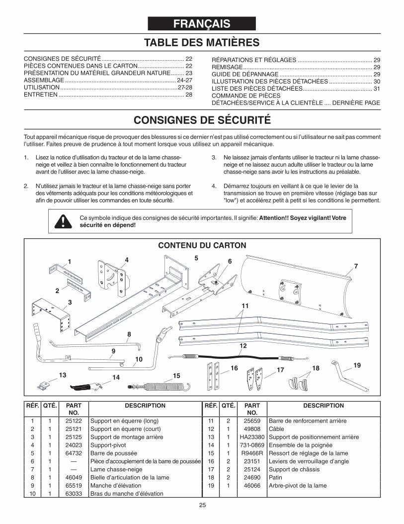
TABLE DES MATIÈRES
RÉPARATIONSETRÉGLAGES ............................................. 29REMISAGE .............................................................................. 29GUIDEDEDÉPANNAGE ........................................................ 29ILLUSTRATIONDESPIÈCESDÉTACHÉES .......................... 30LISTEDESPIÈCESDÉTACHÉES .......................................... 31COMMANDEDEPIÈCESDÉTACHÉES/SERVICEÀLACLIENTÈLE .... DERNIÈREPAGE
Cesymboleindiquedesconsignesdesécuritéimportantes.Ilsignifie:Attention!! Soyez vigilant! Votre sécurité en dépend!
CoNSIGNES DE SÉCURITÉ
CONSIGNESDESÉCURITÉ .................................................. 22PIÈCESCONTENUESDANSLECARTON ............................ 22PRÉSENTATIONDUMATÉRIELGRANDEURNATURE ........ 23ASSEMBLAGE ................................................................... 24-27UTILISATION .......................................................................27-28ENTRETIEN ............................................................................ 28
1. Lisezlanoticed’utilisationdutracteuretdelalamechasse-neigeetveillezàbienconnaîtrelefonctionnementdutracteuravantdel’utiliseraveclalamechasse-neige.
2. N’utilisezjamaisletracteuretlalamechasse-neigesansporterdesvêtementsadéquatspourlesconditionsmétéorologiquesetafindepouvoirutiliserlescommandesentoutesécurité.
3. Nelaissezjamaisd’enfantsutiliserletracteurnilalamechasse-neigeetnelaissezaucunadulteutiliserletracteuroulalamechasse-neigesansavoirlulesinstructionsaupréalable.
4. Démarreztoujoursenveillantàcequelelevierdelatransmissionsetrouveenpremièrevitesse(réglagebassur"low")etaccélérezpetitàpetitsilesconditionslepermettent.
Toutappareilmécaniquerisquedeprovoquerdesblessuressicederniern’estpasutilisécorrectementousil’utilisateurnesaitpascommentl’utiliser.Faitespreuvedeprudenceàtoutmomentlorsquevousutilisezunappareilmécanique.
CoNTENU DU CARToN
RÉF. QTÉ. PART No.
DESCRIPTIoN
1 1 25122 Supportenéquerre(long)2 1 25121 Supportenéquerre(court)3 1 25125 Supportdemontagearrière4 1 24023 Support-pivot5 1 64732 Barredepoussée6 1 — Pièced’accouplementdelabarredepoussée7 1 — Lamechasse-neige8 1 46049 Bielled’articulationdelalame9 1 65519 Manched’élévation10 1 63033 Brasdumanched’élévation
RÉF. QTÉ. PART No.
DESCRIPTIoN
11 2 25659 Barrederenforcementarrière12 1 49808 Câble13 1 HA23380 Supportdepositionnementarrière14 1 731-0869 Ensembledelapoignée15 1 R9466R Ressortderéglagedelalame16 2 23151 Leviersdeverrouillaged’angle17 2 25124 Supportdechâssis18 2 24690 Patin19 1 46066 Arbre-pivotdelalame
8
129
2
1
3
4 6
11
75
10
15
191614
1713
18
FRANÇAIS

26
PIÈCES À L’ÉCHELLE
RÉF. QTÉ PIÈCE No.
DESCRIPTIoN
A 1 46071 Boulonhex.,1/4po.x3-1/4po.B 1 1509-90 Boulonhex.,1/4po.x1-1/4po.C 4 43063 Boulonhex.,5/16po.x1po.D 1 43085 Boulonhex.,5/16po.x1-1/2po.E 4 710-0305 Boulondecarrosserie,3/8po.x1-1/4po.F 18 43350 Boulondecarrosserie,3/8po.x1po.G 3 47189 Contre-écrouennylon,filetage1/4po.H 5 47810 Contre-écrouennylon,filetage5/16po.I 22 HA21362 Contre-écrouennylon,filetage3/8po.J 2 712-0256 Contre-écrouhex.,filetage5/16po.K 1 HA3980 Axedechape,5/8po.x1-3/4po.L 2 44062 Axedechape,1/2po.x1po.M 3 43343 Goupillefendue,grandeN 4 43055 Goupillefendue,petiteO 2 43010 Goupille-épingle,1/8po.x1-1/4po.P 2 44917 Contre-écrouembouti,3/8po.
RÉF. QTÉ PIÈCE No.
DESCRIPTIoN
Q 2 43350 Boulonhex,3/8po.x1po.R 2 43003 Rondelledeblockage,3/8po.S 3 1540-118 Rondelle,1/2po.T 1 23658 Entretoise,9/16po.deD.E.x5/8U 2 46053 Entretoise,9/16po.deD.E.x1V 2 44326 Boulondecarrosserie,5/16-18x1"W 2 43080 Boulondecarrosserie,5/16-18x3/4"X 2 47630 Boulonhex,5/16-18x3/4"Y 4 43081 Rondelle,5/16"Z 4 R19172410 Rondelle,1/2"x1-1/2"AA 2 746-0260 PiècedefixationduboutdecâbleBB 1 05762 SupportdefixationducâbleCC 1 43348 Ressortdeverrouillaged’angleDD 2 726-0178 AttacheenplastiqueEE 1 23856 TigedemontageduressortFF 1 46065 Brochedelabarredepoussée
SAC DE PIÈCES
PIÈCES NoN À L’ÉCHELLE
FRANÇAIS
I
J
H
G
A B
R
S
K
EDQ
M
N
O
P
C
F
L
T U
DD
EE FFCCBBAA
WV X
Z
Y
27
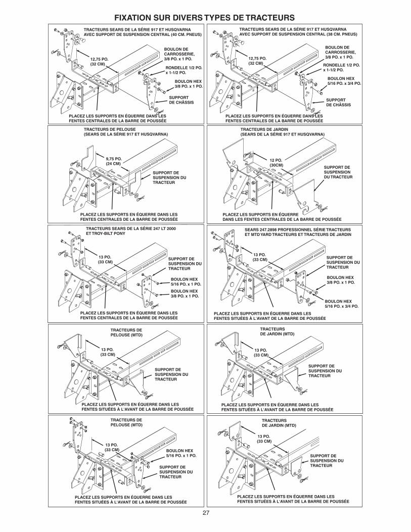
FIXATIoN SUR DIVERS TYPES DE TRACTEURS
BOULON HEX3/8 PO. x 1 PO.
BOULON HEX3/8 PO. x 1 PO.
BOULON HEX5/16 PO. x 1 PO.
BOULON HEX5/16 PO. x 3/4 PO.
SEARS 247.2898 PROFESSIONNEL SÉRIE TRACTEURSET MTD YARD TRACTEURS ET TRACTEURS DE JARDIN
TRACTEURS SEARS DE LA SÉRIE 917 ET HUSQVARNA AVEC SUPPORT DE SUSPENSION CENTRAL (40 CM. PNEUS)
TRACTEURS SEARS DE LA SÉRIE 917 ET HUSQVARNA AVEC SUPPORT DE SUSPENSION CENTRAL (38 CM. PNEUS)
12,75 PO.(32 CM)
BOULON HEX3/8 PO. x 1 PO.
RONDELLE 1/2 PO.x 1-1/2 PO.
BOULON DE CARROSSERIE, 3/8 PO. x 1 PO.
PLACEZ LES SUPPORTS EN ÉQUERRE DANS LES FENTES CENTRALES DE LA BARRE DE POUSSÉE
PLACEZ LES SUPPORTS EN ÉQUERRE DANS LES FENTES CENTRALES DE LA BARRE DE POUSSÉE
SUPPORT DE CHÂSSIS
TRACTEURS DE PELOUSE(SEARS DE LA SÉRIE 917 ET HUSQVARNA)
SUPPORT DE SUSPENSION DU TRACTEUR
PLACEZ LES SUPPORTS EN ÉQUERRE DANS LES FENTES CENTRALES DE LA BARRE DE POUSSÉE
PLACEZ LES SUPPORTS EN ÉQUERRE DANS LES FENTES CENTRALES DE LA BARRE DE POUSSÉE
TRACTEURS DE JARDIN(SEARS DE LA SÉRIE 917 ET HUSQVARNA)
12 PO.(30CM) SUPPORT DE
SUSPENSION DU TRACTEUR
PLACEZ LES SUPPORTS EN ÉQUERRE DANS LES FENTES CENTRALES DE LA BARRE DE POUSSÉE
9,75 PO.(24 CM)
SUPPORT DE SUSPENSION DU TRACTEUR
SUPPORT DE SUSPENSION DU TRACTEUR
13 PO. (33 CM)
13 PO. (33 CM)
SUPPORT DE SUSPENSION DU TRACTEUR
PLACEZ LES SUPPORTS EN ÉQUERRE DANS LES FENTES SITUÉES À L'AVANT DE LA BARRE DE POUSSÉE
TRACTEURS DE PELOUSE (MTD)
TRACTEURS DE PELOUSE (MTD)
SUPPORT DE SUSPENSION DU TRACTEUR
PLACEZ LES SUPPORTS EN ÉQUERRE DANS LES FENTES SITUÉES À L'AVANT DE LA BARRE DE POUSSÉE
BOULON HEX5/16 PO. x 1 PO.
13 PO. (33 CM)
BOULON DE CARROSSERIE, 3/8 PO. x 1 PO.
SUPPORT DE CHÂSSIS
PLACEZ LES SUPPORTS EN ÉQUERRE DANS LES FENTES SITUÉES À L'AVANT DE LA BARRE DE POUSSÉE
TRACTEURS DE JARDIN (MTD)
13 PO. (33 CM)
SUPPORT DE SUSPENSION DU TRACTEUR
PLACEZ LES SUPPORTS EN ÉQUERRE DANS LES FENTES SITUÉES À L'AVANT DE LA BARRE DE POUSSÉE
TRACTEURS DE JARDIN (MTD)
13 PO. (33 CM)
SUPPORT DE SUSPENSION DU TRACTEUR
PLACEZ LES SUPPORTS EN ÉQUERRE DANS LES FENTES SITUÉES À L'AVANT DE LA BARRE DE POUSSÉE
TRACTEURS SEARS DE LA SÉRIE 247 LT 2000ET TROY-BILT PONY
BOULON HEX5/16 PO. x 3/4 PO.
RONDELLE 1/2 PO.x 1-1/2 PO.
13 PO. (33 CM)
12,75 PO.(32 CM)

28
FIXATIoN SUR DIVERS TYPES DE TRACTEURSTRACTEURS JOHN DEERE DE LA SÉRIE D 100
13 PO.(22 CM)
SUPPORT DE CHÂSSIS
BOULON HEX5/16 PO. x 1 PO.
TRACTEURS JOHN DEERE LT
SUPPORT DE CHÂSSIS
PLACEZ LES SUPPORTS EN ÉQUERRE DANS LES FENTES SITUÉES À L'AVANT DE LA BARRE DE POUSSÉE
BOULON HEX5/16 PO. x 1 PO.
13 PO.(22 CM)
PLACEZ LES SUPPORTS EN ÉQUERRE DANS LES FENTES SITUÉES À L'AVANT DE LA BARRE DE POUSSÉE

29
(1) Pinces(1)Marteau(1)Cléàmolette(oucléàdouilles)(1)Cléàfourchede9/16po.ouclépolygonale(2)Cléàfourchede7/16po.ouclépolygonale(2)Cléàfourchede1/2po.ouclépolygonale
oUTILS NÉCESSAIRES PoUR L’ASSEMBLAGE
RETIRER LES PIÈCES DU CARToN• Retirezlesacdepiècesettouteslespiécesducartonet
placez-lesàterrecommeillustréauxpages20et21afindepouvoirlesidentifier.
NoTE IMPoRTANTE: Vousn’aurezpasbesoindetouteslespiècesdusacdepiècesafindefixerlalamechasse-neigeautracteur.Jetezlespiècesdontvousn’avezpasbesoinaprèsavoirterminédemonterlalamechasee-neige.
REMARQUE: Lagauche(LH)etladroite(RH)sontdéterminésenseplaçantassisàlaplaceduconducteur.
ATTENTIoN: Ne pas commencer l’assemblage avantquelemoteurdutracteur,lesilencieuxetledéflecteurdel’échappementaientrefroidis.
UTILISEZ CES INSTRUCTIoNS SI VoTRE TRACTEUR EST ÉQUIPÉ DE DEUX SUPPoRTS AVANT DE FIXATIoN DU PLATEAU DE CoUPE.
ATTENTIoN :repassezàl’étape1sivotretracteurn’estdotéqued'unseulsupportavantdefixationduplateaudecoupe.
ÉTAPE 3 : (VoIR LA FIGURE 3)• MesurezlesdistancesL,Hetl.
L=ladistanceentrelecentredutroudusupportdesuspensionduplateaudecoupeetlapartieavantduchâssisdutracteur. H=ladistanceentrelecentredutroudusupportdesuspensionduplateaudecoupeetlesol. I=ladistanceentrelessupportsdesuspensionduplateaudecoupe.
UTILISEZ CES INSTRUCTIoNS PoUR ToUS LES TRACTEURS.
ÉTAPE 4 : (VoIR LA FIGURE 4)Voustrouverez,àlapage24,desexemplesdeméthodesdefixationdessupportsenéquerreàd’autresmodèlesdetracteur.
• Sélectionnez,enhautdelabarredepoussée,unepairedefentesoffrantundégagementsuffisantentrelalameetlapartieavantdutracteur,toutenminimisantleporte-à-faux.Sélectionnezunepairedefentesenvousbasantsurdistance«L»mesuréeàl'étape2. L=5po(13cm)oumoins.Fixationàl’avantdesdeuxfentes. L=5à7po(13à18cm).Fixationaumilieudesdeuxfentes. L=7à9po(18à23cm).Fixationàl’arrièredesdeuxfentes.
• Disposezlessupportsenéquerredemanièreàcequelesupportcourtsoitàl’intérieurdusupportlongetplacez-lessurlabarredepoussée.Siladistance«H»mesuréeàl’étape2ou3estinférieureà6po(15cm),orientezlessupportsverslebas.Siladistance«H»mesuréeàl’étape2ou3estsupérieureà6po(15cm),orientezlessupportsverslehaut.
• Réglezlalargeurdessupportsenéquerredemanièreàcequ’ellesoitlégèrementinférieureàladistance«l»mesuréeàl’étape2ou3.Centrezlessupportssurlabarredepousséeetfixez-lesàl'aidededeuxboulonsdecarrosseriede3/8pox1-1/4poetdedeuxcontre-écrousennylonde3/8po.
• Serrezlesécrousetvérifiezquelessupportsenéquerrepeuventêtreinsérésentrelessupportsdesuspensionduplateauoulessupportsdechâssisdutracteur.
• Passezàl’étape5delapage7.
ÉTAPE 5 : (VoIR LA FIGURE 5)• Installezlesupportdepositionnementarrièresurledessus
dusupportdemontagearrièreenutilisantdeuxboulonsdecarrosseriede3/8po.x1po.etdeuxcontre-écrouxennylonde3/8po.envous.Serrezlesécrous.
• Installezlesbarresderenforcementarrièresdanslasériedetrouscentrauxsituésdanslescôtésdessupportsdemontagearrièreenutilisantquatreboulonsdecarrosseriede3/8po.x1po.etquatrecontre-écrouxennylonde3/8po.Serrezlesécrousàlamainseulement.
PASSEZ À L’ÉTAPE 3 SI VoTRE TRACTEUR EST ÉQUIPÉ DE DEUX SUPPoRTS AVANT DE FIXATIoN DU PLATEAU DE CoUPE.
UTILISEZ LES INSTRUCTIoNS DE L'ÉTAPE 1 SI VoTRE TRACTEUR EST ÉQUIPÉ D’UN SEUL SUPPoRT AVANT DE FIXATIoN DU PLATEAU DE CoUPE.
ÉTAPE 1 : (VoIR LA FIGURE 1)Voustrouverez,àlapage6,desexemplesdeméthodesdefixationdessupportsdechâssisàd’autresmodèlesdetracteur.
• Maintenezlesupportdechâssisdemanièreàcequelesdeuxtroussetrouventenbasetplacez-lecontrelecôtéduchâssisdutracteursituédevantl’essieuavant.Alignezlesdeuxtroussupérieursdusupportsurlesdeuxtrousduchâssisdutracteur.Faitespivoterlesupportsibesoinest.Fixezlesupportàl’aidedumatérieladéquat.
ÉTAPE 2 : (VoIR LA FIGURE 2)• MesurezlesdistancesL,Hetl.
L=ladistanceentrelecentredestrousinférieursdusupportdechâssisetlapartieavantduchâssisdutracteur. H=ladistanceentrelecentredutroudusupportdechâssisleplusprochede6po(15cm)au-dessusdusol. l=ladistanceentrelespartiesintérieuresdessupportsdechâssis.
• Passezàl’étape4.
PRÉPARATIoN DU TRACTEUR• Laissezlemoteur,lesilencieuxetledéflecteurde
l’échappementrefroidiravantdecommencer.• Retirezleplateaudecoupeoutoutautreaccessoire
frontalquevousavezmontésurletracteurensuivantlesinstructionsdumanueld’utilisationdutracteur.Marqueztouteslespiècesquevousretirezetconservez-lesafindepouvoirlesréutiliserplustard.
FRANÇAIS

30
ÉTAPE 6 : (VoIR LA FIGURE 6)• Faitesglisserlesbarresderenforcementarrièressous
lapartiearrièredutracteur.Fixezlesupportdemontagearrièreàlabarred’attelageàl’aidedel’axedechapede5/8pox1-3/4poetd’unegrandegoupillefendue.
ÉTAPE 7 : (VoIR LA FIGURE 7)• Faitesglisserlabarredepousséesouslapartieavant
dutracteur.Fixezlessupportsenéquerreauxsupportsdechâssisouauxsupportsdesuspensionduplateaudecoupeàl’aidededeuxaxesdechapede1/2pox1po,derondellesde1/2poetd’unegrandegoupillefendue.
ÉTAPE 8 : (VoIR LA FIGURE 8)• Placezlabarredepousséeentrelesdeuxbarresde
renforcementarrières.Installezquatreboulonsdecarrosseriede3/8pox1poetcontre-écrousennylonde3/8podanslestrouslesplusespacés,alignéssurlesfentes.Serreztouslesboulonsmanuellement.
• Silesbarresderenforcementarrièressontencontactavecl’arrièredutracteur,fixezànouveaulapartiearrièredecesbarressurunjeudetrousinférieursdanslesupportdemontagearrière.Silesbarresderenforcementarrièressonttropéloignéesdel’arrièredutracteur,fixezànouveaul’arrièredecesbarresàunjeudetroussupérieursdanslesupportdemontagearrière.
• Resserreztouslesboulonsetécrousdéjàinstallés.• Mesurezlahauteurdelaplaqueavantsurlabarrede
poussée.Siellen’estpasà4ou5po(10ou13cm)audessusdusol,installezànouveaul'axedechapedansuntrouplushautouplusbasdessupportsenéquerre,afind’atteindrelahauteurdésirée.
ÉTAPE 9 : (VoIR LA FIGURE 9)• Montezlesupport-pivotàl’avantdelabarredepousséeen
utilisantquatreboulonsdecarrosseriede3/8po.x1po.etquatrecontre-écrousennylonde3/8po.Assurez-vousquelesupport-pivotestdroitpuisserrezcespièces.
ÉTAPE 10 : (VoIR LA FIGURE 10)• Assemblezlesdeuxleviersdeverrouillaged’anglel’uneà
l’autreenvousréférantàl’illustration8envousassurantquetouslestroussontcorrectementalignés.Utilisezunboulondecarrosseriede3/8po.x1-1/4po.etuncontre-écrouennylonde3/8po.Assurez-vousqueleboulonestinséréàpartirducôtéquiestindiqué.Ne pas serrer pour l’instant.
• Insérezlecrochetarrondisituéàl’extrémitéduressortdeverrouillaged’angleenlefaisantpasserparletrou.
• Tenezlesleviersdeverrouillaged’angledefaçonàcequelestrouscarréssetrouventenhaut.Insérezlecrochetdroitsituéàl’extrémitéduressortdeverrouillaged’angleenlefaisantpasserparletroucentraldesdeuxleviersdeverrouillaged’angleenvous.
• Insérezlesleviersdeverrouillaged’angleàtraverslafentedelabarredepoussée.Souslabarredepoussée,installezuneentretoisede1po.(2,5cm)dechaquecôtédesleviersdeverrouillaged’angleetinsérezunboulonde1/4po.x31/4po.àtraverslabarredepoussée,lesleviersdeverrouillaged’angleetlesentretoises.Fixezleboulonavecuncontre-écrouennylonde1/4po.Serrezcespiècesafinquelesleviersdeverrouillagepuissentpivoterlibrement.
• Serrezàprésentleboulondecarrosseriede3/8po.etlecontre-écriuennylomquevousavezinstallezsurlesleviersdeverrouillaged’angle.
REMARQUE: Lorsquelesleviersdeverrouillaged’angles’effacentdanslafente,laplaque-pivotdevraitsedébloqueretpouvoirtournerversladroiteoulagauche.
ÉTAPE 11 : (VoIR LA FIGURE 11)• Àl’aided’unmarteau,fixezlecontre-écrouemboutide3/8
po.surl’extrémitédelatigedemontageduressort.Insérezl’autreextrémitédelatigedemontageduressortdanslaplaque-pivotenutilisantlasériedetrousarrières.Soutenezl’extrémitéassembléedelatigedemontageduressortsurunblocdeboisetfixezlecontre-écrouemboutisurl’autreextrémitédelatigeenfrappantdessusaveclemarteau.
ÉTAPE 12 : (VoIR LA FIGURE 12)• Installezunboulondecarrosseriede3/8po.x1-1/4po.dans
letroucarrédanslesupportdefixationducâbleetàtraversletroucarrésituédanslesleviersdeverrouillaged’angleenvous.(Lesboulonsdecarrosseriedevraientchacunêtreorientésdansunsensopposé.)Utilisezdespincesafindemaintenirlecâbleenposition,avecl’angleverslebas,versletrougauchedelabarredepousséenvousréférantàl’illustration10.Fixezlespiècesenutilisantuncontre-écrouennylonde3/8po.Serrez ces pièces.Reportez-vouségalementàl’illustration14afindevoirl’angledepositionnementdusupportdefixationducâble.
ÉTAPE 13 : (VoIR LA FIGURE 13)• Sélectionnezl’extrémitéducâbledecommandequin’a
pasdecapuchonencaoutchouc.Insérez3/4pod’uncontre-écrouhexagonalde5/16posurl’extrémitéfiletéeducâbledecommande.Insérezl’extrémitéfiletéedecâbledansletrouronddusupportdemontageducâble,commecelaestillustréetfixez-leàl’aided’unautrecontre-écrouhexagonal.Serrezletout.
REMARQUE :vousdevrezéventuellementréglerlescontre-écroushexagonauxunefoislalameassemblée.
ÉTAPE 14 : (VoIR LA FIGURE 14)• Insérezverslehautleboutsphériqueducâblede
commandedansletroudelapiècedefixationduboutducâblepuistirezjusqu’àcequelabouleglisseàl’intérieurdubordbouclédelapièceenvous.Silabouleneglissepassousleborddelaboucle,elledevraêtreintroduitedansleboutouvertdelaboucle.
• Installezunboulonhex.de1/4po.x1-1/4po.enlepassantverslebasàtraverslapiècedefixationduboutdecâble,l’entretoiselonguede5/8po.puisletrougauchedelabarredepoussée.Fixezleboulonenutilisantuncontre-écrouennylonde1/4po.Serrez le contre-écrou.
REMARQUE: Assurez-vous que lesupportdefixationducâbleestbienalignésurlapiècedefixationduboutducâbleenvousréférantàl’illustration12afind’éviterdecoincerlecâble.Vousfixezl’autreextrémitéducâbledecommandeplusloindanscemanuel.
FRANÇAIS

31
ÉTAPE 15 : (VoIR LA FIGURE 15)• Pourfixerlalameàlabarredepoussée,alignezlestrousde
laplaque-pivotsurlestrousàencochesdelalame.Insérezverslebasunegoupille-épinglede1/8po.x1-1/4po.dansletrousituédanslecoudedel’arbre-pivotdelalame.Écartezlesextrémitésdelagoupille-épingle.Àpartirducôtégauche,introduisezl’arbre-pivotdelalame,aveclecoudeorientéverslehaut,danslestrousàencoches.Fixezl’arbreavecuneautregoupille-épinglede1/8po.x1-1/4po.dansletrousituéauboutdel’arbre.Écartezlesextrémitésdelagoupille.
• Retirezlecapuchonenplastiqueetunécrouhex.de3/8po.duboulonduressortderéglagedelalame.Réglezl’écrouhex.restantde3/8po.enlefaisantdescendreenviron1po.(2,5cm)surlefiletageduboulon.Accrochezleressortsurlatigedemontageduressort.Insérezleboulonverslehautenlefaisantpasseràtraversletrousituédanslebordsupérieurdelalameetremettezenplacel’autreécrouhex.de3/8po.puisserrez-lecontrelebordsupérieurdelalame.Remettezenplacelecapuchonenplastiquesurleboutdufiletageduboulon.
ÉTAPE 16 : (VoIR LA FIGURE 16)• Installezunerondellede1/2po.surlabrochedelabarrede
poussée.• Fixezlabarredepousséeautracteurenplaçantlebout
delabarredepousséeàl’intérieurdusupport-pivotsurletracteur.Alignezletroudusupport-pivotsurletroudeuxièmetrouenpartantdel’arrièredelabarredepoussée.Insérezlabrochedelabarredepousséedanslestrousquevousvenezd’alignerenl’insérantàpartirducôtégaucheetfixez-laenutilisantungoupillefenduequevousintroduirezcomplètementjusqu’àl’extrémitéenformedeboucle.
REMARQUE:Touteslesgoupillesfenduesdecettelamechasse-neigedoiventêtreinséréesenlespoussantjusqu’àl’extrémitéenformedeboucle.
ÉTAPE 17 : (VoIR LA FIGURE 17)• Àpartirducôtégauche,insérezleboutsoudédubras
dumanched’élévationdanslestrousvisiblessituésàl’extrémitédelabarredepoussée.Ensuite,insérezlatiged’élévationdansletroudusupportquiestsoudéaubrasdumanched’élévation.(Latiged’élévationestpré-assembléeausupport-pivot).Fixezlesupporteninsérantunegoupillefenduedanslatiged’élévationjusqu’àl’extrémitéenformedeboucledelagoupille.
• Utilisezlapetitepochettedegraissefournieetappliquezunefinecouchedegraissesurlapartiesupérieuredubrasdumanched’élévation.Glissezlemanched’élévationsurlebras.
FRANÇAISPASo 18: (VEA LA FIGURA 18)• Faitespivoterlalameverslapositioncentralepuis
abaissez-lajusqu’àcequ’elletouchelesol.Placezlescalessouslalameafindelaisserl’espaceausolquevousdésirez.Pluslasurfacedusolestinégale,plusl’espaceausoldoitêtreimportante.
• Fixezlespatinsàlalameenplaçantunboulondecarrosseriede5/16pox3/4podansletrousupérieuretunboulondecarrosseriede5/16pox1podansletrouinférieur.Unefoisquelespatinsreposentausol,placezlesrondellesde5/16poetlescontre-écrousennylonde5/16po.
ÉTAPE 19 : (VoIR LA FIGURE 19)• Retirezlecapuchonencaoutchoucetlepremier
contre-écrouhexagonaldel’extrémitéfiletéeducâbledecommandeetfaites-lesglissersurlefilducâbledecommande.Réglezledeuxièmecontre-écrousurlesfiletagesdemanièreàcequ’ilsoitàenviron3/4podel’extrémité.Insérezl’extrémitéfiletéedecâbledanssonsupportdemontage,surlemanched’élévationetfixez-laàl’aidedupremiercontre-écrou.Installezànouveaulecapuchonencaoutchoucsurl’extrémitéfiletéeducâble.
REMARQUE :vousdevrezéventuellementréglerlescontre-écroushexagonauxunefoislalameassemblée.
ÉTAPE 20 : (VoIR LA FIGURE 20)• Installezlapoignéeenplastiquesurl’ensembledela
poignéededéblocage.• Fixezl’ensembledelapoignéededéblocagesurle
manched’élévationenutilisantunboulonhex.de5/16po.x1-1/2po.etuncontre-écrouennylonde5/16po.Ne pas trop serrerlecontre-écrouennylon.L’ensembledelapoignéedoitpouvoirtournerlibrement.
• Insérezleboutsphériqueducâbledansunedespiècesdefixationduboutdecâblecommevousl’avezfaitpourl’autreextrémitéducâble.Fixezlapiècedefixationduboutdecâbleauboulonsoudédelapoignéededéblocageenutilisantuncontre-écrouennylonde1/4po.Ne pas trop serrerlecontre-écrouennylon.Lapiècedefixationduboutdecâbledoitpouvoirtournerlibrement.
ÉTAPE 21 : (VoIR LA FIGURE 21)• Faitespasserleboutlongdelabielled’articulationdela
lameverslebas,dansl’arbre-pivotdelalame.Fixezleboutcourtdelabielled’articulationdelalamesurlemanched’élévation.Fixezlesdeuxboutseninsérantungoupillefenduedanschaqueboutjusqu’àlaboucledelagoupille.
• Utilisezlesdeuxattachesenplastiqueafindemaintenirlecâblefermementsurl’extérieurdumanched’élévationetàl’écartdutracteurafind’évitertoutechaleurdirecteprovenantdusilencieuxdutracteur.
32
FRANÇAIS
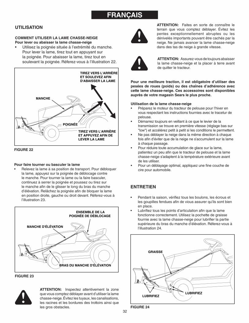
ATTENTIoN: Inspectez attentivement la zonequevouscomptezdéblayeravantd’utiliserlalamechasse-neige.Évitezlestuyaux,lescanalisations,lesracinesetlesborduresdestrottoirsainsiquelesgrosobstacles.
ATTENTIoN: Faites en sorte de connaître leterrain que vous comptez déblayer. Évitez lespentes exceptionnellement abruptes ou lesdénivelésimportantspouvantêtrecachésparlaneige.Nejamaisavancerlalamechasse-neigedansdestasdeneigeàgrandevitesse.
ATTENTIoN: Assurez-vousdetoujoursabaisserlalamechasse-neigeetlaplaceràterreavantdequitterletracteur.
ENTRETIEN
• Pendantlasaison,vérifieztouslesboulons,lesécrousetlesgoupillesfenduesafindeviousassurerqu’ilssontbienenplace.
• Lubrifieztouslespointsd’articulationafinquelalamefonctionnecorrectement.Utilisezlapochettedegraissefournieaveclalamechasse-neigepourlubrifierlapartiesupérieuredubrasdumanched’élévation.Réferez-vousàl’illustration24.
Pour une meilleure traction, il est obligatoire d’utiliser des pesées de roues (poids) ou des chaînes d’adhérence avec cette lame chasse-neige. Ces accessoires sont disponibles auprès de votre magasin Sears le plus proche.
Utilisation de la lame chasse-neige• Préparezlemoteurdutracteurdepelousepourl’hiveren
vousrespectantlesinstructionsfourniesavecletraceturdepelouse.
• Démarreztoujoursenveillantàcequelelevierdelatransmissionsetrouveenpremièrevitesse(réglagebassur"low")etaccélérezpetitàpetitsilesconditionslepermettent.
• Nepasdéblayerlaneigedanslamêmedirectionàchaquefoisafind’éviterquedelaneigenes’accumulentsurlalameàchaquepassage.
• Pourréduiretouteaccumulationdeglacesurlalame,patientezunpeuafinqueletracteurdepelouseetlalamechasse-neiges’adaptentàlatempératureextérieureavantdelesutiliser.
• Pourundéblayageoptimal,appliquezunefinecouchedecirepourautomobile.
GRAISSE
LUBRIFIEZ LUBRIFIEZ
FIGURE 24
UTILISATIoN
CoMMENT UTILISER LA LAME CHASSE-NEIGEPour lever ou abaisser la lame chasse-neige• Utilisezlapoignéesituéeàl’extrémitédumanche.
Pourleverlalame,tireztoutenappuyantsurlapoignée.Pourabaisserlalame,tireztoutensoulevantlapoignée.Réferez-vousàl’illustration22.
FIGURE 23
MANCHE D'ÉLÉVATION
ENSEMBLE DE LAPOIGNÉE DE DÉBLOCAGE
BRAS DU MANCHE D'ÉLÉVATION
MANCHE
TIREZ VERS L'ARRIÈREET SOULEVEZ AFIND'ABAISSER LA LAME
TIREZ VERS L'ARRIÈREET APPUYEZ AFIN DELEVER LA LAME
POIGNÉE
FIGURE 22
Pour faire tourner ou basculer la lame• Relevezlalameàsapositiondetransport.Pourdébloquer
lalame,appuyezsurlapoignéededéblocagecontrelemanche.Pourtournerlalameoulafairebasculer,continuezàserrerlapoignéeetpoussezoutirezsurlemancheafindeleglisserlelongdubrasdumanched’élévation.Relâchezlapoignéeafindebloquerlalameenpositiondroite,gaucheoudroitdevant.Réferez-vousàl’illustration23.

33
RÉPARATIoNS ET RÉGLAGES
Pour régler la tension du ressort de la lame• Vouspouvezchangerlatensionduressortderéglagede
lalamepourquelalamepuissebasculerversl’avantafind’éviterlesobstacles.Pourmodifierlatensionduressort,réglezlesécroussituésàl’extrémitésupérieureduboulonduressort.Tournezlesécrousdanslesensinverseàceluidesaiguillesd’unemontreafinderéduirelatensionetdanslesensdesaiguillesd’unemontreafind’augmenterlatension.Réferez-vousàl’illustration15delapage10.
Pour régler les patins• Lespatinssituésauxextrémitésdelalamepeuventêtre
relevéssivousdevezdéblayerdessurfaceslissesouabaissésafindebaisserlalamesivousdevezdéblayerdessurfacesirrégulièresouaccidentées.Assurez-vousquelesdeuxpatinsontétéréglésdefaçonégaleetquelesécrousontétéresserrésfermement.Réferez-vousàl’illustration25. REMISAGE
Recommandations pour le remisage• Lorsquevousn’utilisezpaslalamechasse-neige,retirez
laterreetlestracesderouilleseteffectuezlesretouchesnécessairesavecdelapeinture.
• Effectuezlesretouchesnécessairessurlemetalnuavecdelapeintureouappliquezunefinecouchedegraisseouavecunantirouille.
• Lubrifieztouslespointsd’articulationettouslespointsindiquésàl’illustration24delapage30danslechapitre"Entretien".
• Remiserl’équipementdansunendroitsecàl’abridesintempéries
Pour retirer la lame chasse-neige du tracteur• Abaissezlalameetplacez-laàterreenlalaissanten
positioncentrale(droitenavant).• Retirezlesdeuxaxesdechapequiretiennentlessupports
enéquerreauxsupportsdesuspensionduplateaudecoupedutracteur(ouauxsupportsdechâssis).Réferez-vousàl’illustration7delapage8.
• Retirezl’axedechapequiretientlesupportdemontagearrièredelalameàlabarred’attelagedutracteuretlaisseztomberausoll’arrièreducadredelalameRéferez-vousàl’illustration6delapage8.
• Retirezlessupportsdechâssis(sivouslesavezutilisés).Réferez-vousàl’illustration1delapage4.
• Faitesunemarchearrièreavecletracteurafindeledécrocherl’ensembledelalame.
GUIDE DE DÉPANNAGE
FRANÇAIS
PATIN
SUPPORT DE CÂBLE SOUDÉ
CONTRE-ÉCROUHEX. 5/16 PO.
CÂBLE DECOMMANDE
CONTRE-ÉCROUHEX. 5/16 PO.
Pour régler le mécanisme de blocage de l’articulation de la lame• Silalamenesedébloquepasetnepeuttournernibasculer,
lesleviersdeverrouillaged’anglenesortentpasdesfentesdelaplaque-pivot.Pourcorriger leproblème, réglez lescontre-écroushex.de5/16po.afindepouvoirtirersurl’extrémitéducâbleverslesupportdecâblesoudé.Moinsl’extrémitéfiletéeducâbledépassedusupportdecâblesoudéetpluslesleviersdeverrouillaged’anglepourrontsortiretcomplètementseretirerdesfentesdelaplaque-pivot.Réferez-vousàl’illustration26.
FIGURE 25
FIGURE 26
PRoBLÈME CAUSE MESURE CoRRECTIVELalameestdifficileàlever. Lemécanismed’élévationgrippe. Lubrifiezlespointsd’articualtioncomme
indiquéàl’illustration24delapage32.
Lalameestdifficileàtournerouàfairebasculerversl’avant.
Lemanchecolleaubrasd’élévation. Lubrifiezlebrasdumanched’élévationcommeindiquéàlapage32.
Lalamenesedébloquepaspourtourner. Lemécanismedeverrouillageestdérégléetnesedégagepas.
Reportez-vousauchapitre"Réparationsetréglages"delapage33.

34
REPAIR PARTS LIST FoR MoDEL LBD48D 48" SNow BLADE
44, 6
3
6, 5
26,
52
59
28
48
595261
2955
58
51
61
55
58
B
B A
A
3
8
8
10
30
35
35
50
3334
45
38
23
46
32
4256
15
14
19
3940
24
27
20
48
4837
47
41
41
25
36
25
25
4141
11
36
21
21
17
13
647
43
12
26
4
54
4
7
76
6
6
6
47
31
5536
25
C
C
5754
2
1
22
4952
52
38
D
D
5158
5260
53
51
5252
18
16
16
52
51
51
51
51
519
52
52
52
63, 6
4 62
66
OP
TIO
NA
L A
CC
ES
SO
RY
6552
63

35
the fastest way to purchase parts www.speedepart.com
REPAIR PARTS LIST FoR MoDEL LBD48D 48" SNow BLADE
RE
F.
No
.PA
RT
No
.Q
TY.
DE
SC
RIP
TIo
N
1 23
955
1Blade
48"
2 23
956
1Wea
rPlate48"
3 62
980
1Reinforce
men
tPlateAssem
bly
4 43
080
6Bolt,Carria
ge5/16-18
x3/4"
5 44
326
4Bolt,Carria
ge5/16-18
x1"
6 47
810
15Nylon
Loc
kNut,5
/16-18
7 43
081
4Was
her,5/16
"8
2469
02
SkidSho
e9
6473
21
Thrus
tCha
nnel
10
2434
71
Pus
hCha
nnel
11
4326
21
Hex
Loc
kNut,1
/2-13
12
2313
11
Bolt,Spe
cialPivot
13
1540
-118
1Was
her,Flat1/2"
14
2395
81
Plate,P
ivot7G
a.15
23
130
1Bracket,S
pringMt.
16
2465
92
Rea
rSup
portCha
nnel
17
4606
61
Sha
ft,Blade
Pivot
18
2512
51
Rea
rMou
ntingBracket
19
9466
R1
Spring,Blade
Adjus
t20
44
071
1Hex
Bolt,3/8-16
x3-1/2"
21
4301
52
Hex
Nut,3
/8-16
22
4407
41
PlasticCap
23
4980
81
Con
trolCab
leAssem
bly
24
6256
11
Relea
seG
ripAssem
bly
25
4305
54
Pin,H
airpinSmall3
/32"
26
4605
32
Spa
cer,.2
8IDx1"
27
6303
31
LiftHan
dleRod
Assem
bly
28
2512
11
Sho
rtHan
gerBracket
29
2512
21
Long
Han
gerBracket
30
2402
31
PivotSup
portBracket
31
4816
71
Rod
,Blade
Pivot
32
6551
91
LiftHan
dleTu
beAssem
bly
33
2315
12
Ang
leLoc
kBar
34
2385
61
SpringM
ountRod
RE
F.
No
.PA
RT
No
.Q
TY.
DE
SC
RIP
TIo
N
35
4491
72
Palnu
t,3/8"
36
4301
03
CotterPin1/8"x1-1/4"
37
4334
81
Ang
leLoc
kSpring
38
746-
0260
2Cab
leEnd
Fitting
39
731-
0869
1Grip
,Plastic
40
4647
11
Han
dle,G
rip
41
712-
0256
2Hex
Jam
Nut,5
/16-24
42
2365
81
Spa
cer
43
4308
51
Hex
Bolt,5/16
-18x1-1/2"
44
4306
34
Bolt,Hex
5/16-18
x1"
45
0576
21
Cab
leM
ountBracket
46
1509
-90
1Hex
Bolt1
/4-20x1-1/4"
47
4718
93
Nylon
Loc
kNut,1
/4-20
48
710-
0305
4Carria
geBolt,3/8-16
x1-1/4"
49
4606
51
Cha
nnelPivotPin
50
6303
41
LiftLink
Assem
bly
51
4335
018
Carria
geBolt,3/8-16
x1"
52
HA21
362
22Nylon
Loc
kNut,3
/8-16
53
HA23
380
1Rea
rLo
catin
gBracket
54
726-
0178
2PlasticTie
55
R19
1716
163
Was
her.1/2"x1"x.059
"Thin
56
4607
11
Hex
Bolt,1/4-20
x3-1/4"
57
4334
91
1/4"x1"SpringPin
58
4334
33
Pin,3
/32"Hairpin(La
rge)
59
4406
22
ClevisPin,1
/2"x1"Lg.
60
HA39
801
ClevisPin,5
/8"x1-3/4"Lg.
61
2512
42
Fram
eBracket
62
4300
32
LockW
ashe
r,3/8"
63
4300
14
Hex
Bolt,3/8-16
x1"
64
4763
02
Hex
Bolt,5/16
-18x3/4"SelfT
hd65
R
1917
2410
4Was
her,1/2"x1-1/2"x.134
"66
66
754
1Rub
berBlade
Kit(notin
clud
ed)
4236
31
Owne
rsM
anua
l

the fastest way to purchase parts www.speedepart.com
REPAIR PARTSAgri-Fab,Inc.
809SouthHamiltonSullivan,IL.61951
217-728-8388www.agri-fab.com©2004Agri-Fab,Inc.