daniel stockton - xfem presentation
TRANSCRIPT

XFEM Analysis of Cold
Hole Expansion
Daniel Stockton
2/24/2015

Table of Contents
• Successes:
– Repeat Past XFEM Studies
– Study Mesh Sensitivities
– Cold Expansion with Coarse Mesh
– SIF – Coarse Mesh w/ & w/o Residual Stress
– SIF – Fine Mesh w/o Residual Stress
– Putting Crack into Deformed Mesh
• Next Studies
• Issues

Success:
Repeat of past XFEM Studies
• XFEM Modeling of Mixed-
Mode Cracks in Thin Aluminum
Panels
• 30°, 60° and 90° crack, w.r.t. to
tensile direction, placed in
center
• Displacement until failure
• Abaqus version 6.9
Displacement
Clamped
90° crack 60° crack 30° crack

Success:
Repeat of past XFEM Studies
• XFEM Modeling of Mixed-
Mode Cracks in Thin Aluminum
Panels
Paper’s Results
My Results Abaqus v6.12
90° crack 60° crack 30° crack

Success:
Repeat of past XFEM Studies
1500
1600
1700
1800
1900
2000
2100
2200
2 3 4 5 6 7
Max
Re
acti
on
Fo
rce
, N
Nominal Crack Length, mm
Reaction Force vs Nominal Crack Length
Experimental Results My Simulation Results Paper's Simulation Results
Crack Angle Experimental
Force, N
My Simulation
Force, N
My Error
Paper's Simulation
Force, N
Paper's Error
30° 2162 2071 4.2% 2122 -1.9%
60° 1784 1694 5.0% 1864 4.4%
90° 1695 1601 5.5% 1686 -0.5%

Success:
Study Mesh Sensitivities
• Crack is placed and will jump to next element mesh line along the same
path as the crack.
• XFEM does not work when starting from a mesh line perpendicular to force
direction.
• Why? Because it needs to create two new phantom nodes along the same
direction as the force.

Success:
Study Mesh Sensitivities
• Mesh slightly modified.
• XFEM crack jumps to mesh line not perpendicular to the force.
• Crack propagates as expected.
XFEM Crack Placed XFEM Crack Jumps XFEM Crack Propagates

Success:
Study Mesh Sensitivities
• Basic concept for XFEM is that two new phantom mesh nodes are created
in place of the crack intersection.
• However, a crack along the mesh line will not separate in my experience.
New phantom
nodes
Success:
Study Mesh Sensitivities
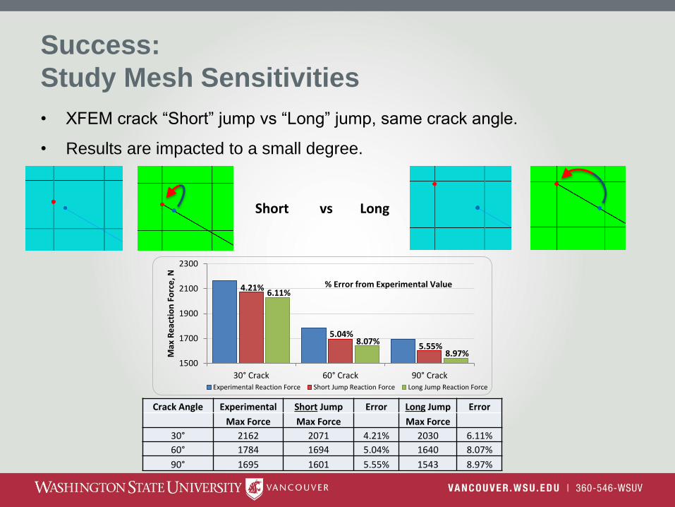
• XFEM crack “Short” jump vs “Long” jump, same crack angle.
• Results are impacted to a small degree.
Short vs Long
Crack Angle Experimental Short Jump Error Long Jump Error
Max Force Max Force Max Force
30° 2162 2071 4.21% 2030 6.11%
60° 1784 1694 5.04% 1640 8.07%
90° 1695 1601 5.55% 1543 8.97%
4.21%
5.04%
5.55%
6.11%
8.07%
8.97% 1500
1700
1900
2100
2300
30° Crack 60° Crack 90° Crack
Max
Re
acti
on
Fo
rce
, N
Experimental Reaction Force Short Jump Reaction Force Long Jump Reaction Force
% Error from Experimental Value
Success:
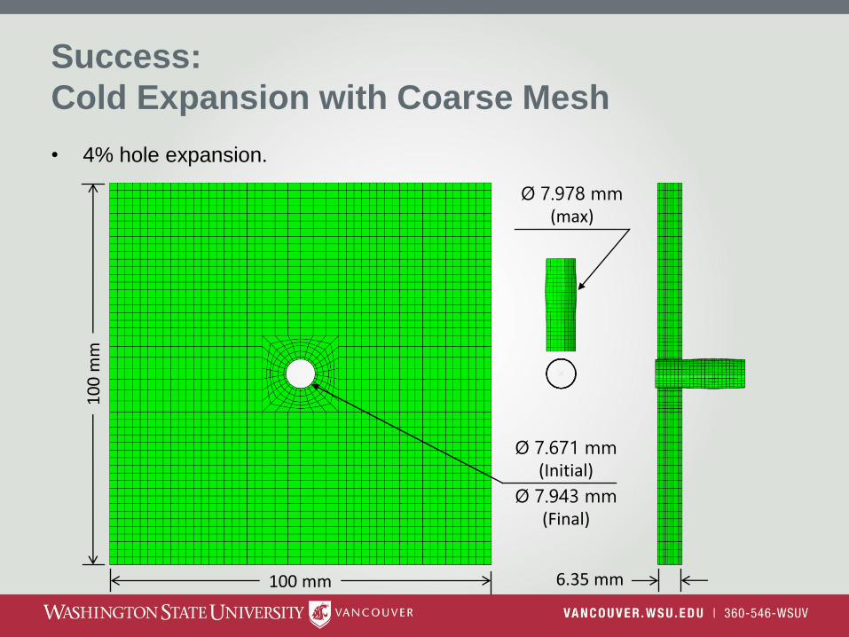
Cold Expansion with Coarse Mesh
• 4% hole expansion.
100 mm
10
0 m
m
6.35 mm
Ø 7.671 mm (Initial)
Ø 7.978 mm (max)
Ø 7.943 mm (Final)

Success:
Cold Expansion with Coarse Mesh
Residual Stresses after 4% Expansion

Success:
Cold Expansion with Coarse Mesh
• Residual Stresses after 4% expansion, Entry and Exit.
-700.00
-600.00
-500.00
-400.00
-300.00
-200.00
-100.00
0.00
100.00
200.00
0 0.01 0.02 0.03 0.04 0.05
Stre
ss (
MP
a)
Distance from Hole (m)
3D - Residual Stresses
Entry Tangential
Exit Tangential
Entry Radial
Exit Radial
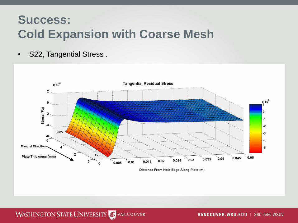
Success:
Cold Expansion with Coarse Mesh
• S22, Tangential Stress .

Success:
Stress Intensity Factor, SIF
• Contour integral method used to calculate stress intensity factor
• Each ring is a an individually calculated contour around the crack opening
• Ring is based off of mesh, user specifies # of rings.
• SIF value should converge as the number of rings increase
Converged Value
Ring 1 Ring 2 Ring 3 Ring 4
Ring 1
Ring 2
Ring 3 Ring 4 Ring 5 Ring 6 Ring 7
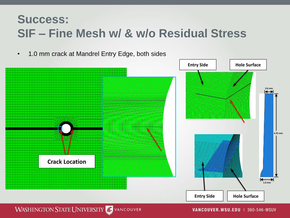
Success:
SIF – Fine Mesh w/ & w/o Residual Stress
• 1.0 mm crack at Mandrel Entry Edge, both sides
Crack Location
Entry Side Hole Surface
Entry Side Hole Surface
1.0 mm
0.6 mm
6.35 mm
Success:
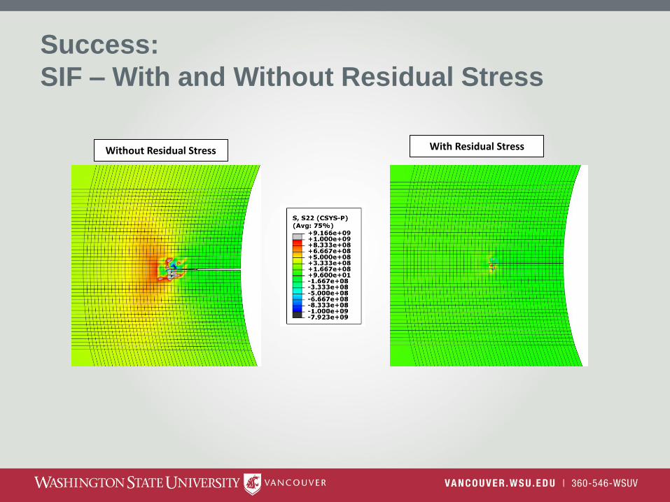
SIF – With and Without Residual Stress
With Residual Stress
Without Residual Stress

Success:
SIF – With and Without Residual Stress
• Crack Opening comparison
• 5x Deformation Scale
Without Residual Stress With Residual Stress
Crack Opening
Crack Opening

Success:
SIF – With and Without Residual Stress
• Stress intensity factor contour integrals.
Stress intensity factor = 26.2 𝑀𝑃𝑎 𝑚
Stress intensity factor = 8.1 𝑀𝑃𝑎 𝑚

Next Studies
• Low-Cycle fatigue in steps.
– Low-cycle fatigue maximum of 10,000 cycles
• Continue to high-cycle Fatigue correlation.
– XFEM only does low-cycle fatigue
• Al-Li fatigue testing

• Meshing
– Depends on crack size but always difficult with super fine mesh
• Cold Expansion with Fine Mesh
– Static: Large overpenetration except with Reduced Integration
– Implicit: Too slow and large penetration
– Explicit: Too slow
• Equilibrium of Residual Stresses
– If Equilibrium step used then residual stresses shift.
• Deformed Part
– Currently pulled from ODB but orphan mesh.
Issues:
THE END
Thank you