cf1 - cf2 - pro.aldes.fr · - detección de temperatura elemento de respuesta y la carga portante...
TRANSCRIPT
CF1 - CF2
1396 - CPD - 0055
www.aldes.com
Alde
s CF1
-CF2
- in
d E
GB Original Installation, Operation and Maintenance manual Terminal fire Damper
DE Die original Anleitung für Installation, Betrieb und Kontrolle Endseitige Brandschutzklappe
FR Manuel original d’installation, d’exploitation et de contrôle Clapet terminal coupe-feu
NL Originele Installatie-, Bedienings- en Onderhoudsvoorschriften Eindklep voor brandgevel
IT Manuale originale di installazione, uso e manutenzione Serranda tagliafuoco terminale
ES Manual original de instalación, uso y mantenimiento Válvula terminal cortafuego
Notice de Montage


3
GB Conformities
DE Abweichungen
12 1396
1396 - CPD - 0055EN 15650 : 2010
12 1396
1396 - CPD - 0055EN 15650 : 2010
Fire damper cartridge:
CF1 El 60S Ø 100 -200 ZV-DV1CF2 EI120S Ø 100 -200 ZV-DV1
Brandschutzklappe:
CF1 El 60S Ø 100 -200 ZV-DV1CF2 EI120S Ø 100 -200 ZV-DV1
Nominal activation PassConditions / sensitivity:- Sensing element load bearing capacity- Sensing element response temperature
Response delay (response time) Pass- Closure time
La fiabilité de fonctionnement :- Cyclisme 50 cycles pass
Operational reliability- Maintenance of the cross section (under E)- Integrity E EI60/1 20 (ve ho i o) S- lnsulation I- Smoke leakage S- Mechanical stability (under E)- Cross-section (under E)
Durability of response delay- Sensing element response temperature and load bearing capacity Pass
Durability of operational reliability- Open and closing cycle Pass
Nominale Aktivierung ErfülltNennbedingungen der Aktivierung / Empfindlichkeit:- Belastbarkeit des temperaturempfindlichen Messfühlers- Ansprechtemperatur des temperaturempfindlichen Messfühlers
Ansprechverzögerung (Ansprechzeit) Erfüllt- Temps de fermeture
Betriebssicherheit- Zyklische Prüfung 50 Zyklen - erfüllt
Feuerwiderstand:- Beibehaltung des Querschnitts (bzgl. E)- Raumabschluss E EI60/1 20 (ve ho i o) S- Wärmedämmung I- Rauchleckage S- Mechanische Festigkeit (unter E)- Querschnitt (unter E)
Ansprechzeit- Ansprechen des temperaturempfindlichen Messfühlers auf Temperatur und Belastbarkeit Erfüllt
Dauerhaftigkeit der Betriebssicherheit- Prüfungen des Öffnungs - und Schließzyklus Erfüllt
4
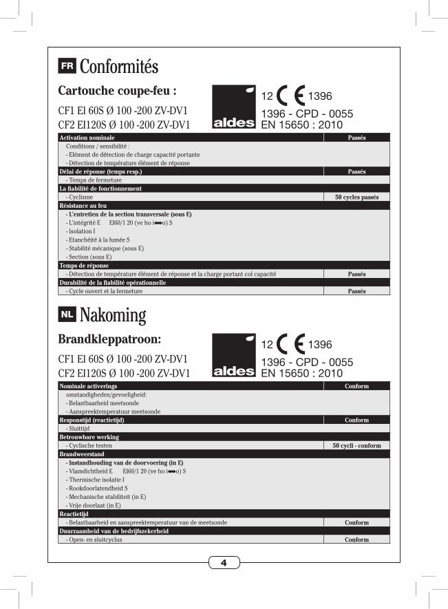
FR Conformités12 1396
1396 - CPD - 0055EN 15650 : 2010
Cartouche coupe-feu :
CF1 El 60S Ø 100 -200 ZV-DV1CF2 EI120S Ø 100 -200 ZV-DV1Activation nominale Passés
Conditions / sensibilité : - Elément de détection de charge capacité portante- Détection de température élément de réponse
Délai de réponse (temps resp.) Passés- Temps de fermeture
La fiabilité de fonctionnement- Cyclisme 50 cycles passés
Résistance au feu- L’entretien de la section transversale (sous E)- L’intégrité E EI60/1 20 (ve ho i o) S- lsolation I- Etanchéité à la fumée S- Stabilité mécanique (sous E)- Section (sous E)
Temps de réponse- Détection de température élément de réponse et la charge portant col capacité Passés
Durabilité de la fiabilité opérationnelle- Cycle ouvert et la fermeture Passés
NL Nakoming12 1396
1396 - CPD - 0055EN 15650 : 2010
Brandkleppatroon:
CF1 El 60S Ø 100 -200 ZV-DV1CF2 EI120S Ø 100 -200 ZV-DV1Nominale activerings Conform
omstandigheden/gevoeligheid:- Belastbaarheid meetsonde- Aanspreektemperatuur meetsonde
Responstijd (reactietijd) Conform- Sluittijd
Betrouwbare werking- Cyclische testen 50 cycli - conform
Brandweerstand- Instandhouding van de doorvoering (in E)- Vlamdichtheid E EI60/1 20 (ve ho i o) S- Thermische isolatie I- Rookdoorlatendheid S- Mechanische stabiliteit (in E)- Vrije doorlaat (in E)
Reactietijd- Belastbaarheid en aanspreektemperatuur van de meetsonde Conform
Duurzaamheid van de bedrijfszekerheid- Open- en sluitcyclus Conform

5
IT Conformità12 1396
1396 - CPD - 0055EN 15650 : 2010
Cartuccia tagliafuoco:
CF1 El 60S Ø 100 -200 ZV-DV1CF2 EI120S Ø 100 -200 ZV-DV1Attivazione normale Conforme
Condizioni / sensibilità:- Elementi di rilevamento di carico capacità portante- Rilevamento di temperatura elemento di risposta
Tempo di risposta (tempo risp.) Conforme- Tempo di chiusura
Affidabilità del funzionamento- Ciclicità 50 cicli - conformi
Resistenza al fuoco- La manutenzione della sezione trasversale (sotto E)- L’integrità E EI60/1 20 (ve ho i o) S- Isolamento I- Tenuta al fumo S- Stabilità meccanica (sotto E)- Sezione (sotto E)
Tempo di risposta- Rilevamento di temperatura elemento di risposta e carico portante collo capacità conforme Conforme
Durabilità dell’affidabilità operativa- Ciclo aperto e chiusura Conforme
ES Conformidad12 1396
1396 - CPD - 0055EN 15650 : 2010
Cartucho cortafuego:
CF1 El 60S Ø 100 -200 ZV-DV1CF2 EI120S Ø 100 -200 ZV-DV1Activación nominal Confirme
Condiciones/sensibilidad:- Elementos de detección de carga capacidad portante- Detección de temperatura elemento de respuesta
Plazo de respuesta (tiempo de resp.) Confirme- Tiempo de cierre
La fiabilidad de funcionamiento- Ciclismo 50 ciclos – conforme
Resistencia al fuego- El mantenimiento de la sección transversal (en E)- La integridad E EI60/1 20 (ve ho i o) S- Aislamiento I- Estanqueidad al humo S- Estabilidad mecánica (en E)- Sección (en E)
Tiempo de respuesta- Detección de temperatura elemento de respuesta y la carga portante cuello capacidad Confirme
Durabilidad de la fiabilidad operacional- Ciclo abierto y el cierre Confirme

6
InstallationCF1 - CF2
1 - Wall, 2 - Gypsum / Mortar/ Concrete, 3 - Steel duct, 4 - CF1 - CF2, 5 - Disc valve1 - Decke, 2 - Gips / Mörtel / Beton, 3 - Stahlrohr, 4 - CF1 - CF2, 5 - Ventil1 - Paroi, 2 - Plâtre / Mortier / Béton, 3 - Gaine acier, 4 - CF1 - CF2, 5 - Bouche ventilation1 - Plafond, 2 - Gips, 3 - Stalen kanaal, 4 - CF1 - CF2, 5 - Ventiel1 - Parete, 2 - Gesso / Malta / Cemento, 3 - Condotto in acciaio, 4 - CF1 - CF2, 5 -Valvola 1 - Pared, 2 - Yeso / Mortero / Hormigón, 3 - Conducto metálico, 4 - CF1 - CF2, 5 -
Boca de ventilación
Fig.1 Embedding of the terminal fire damper using gypsum/mortar/concreteAbb. 1 Installation einer Endseitige Brandschutzklappe mit Gips/Mörtel/BetonFig.1. Scellement d’un clapet terminal coupe-feu à l’aide du plâtre/mortier/bétonFig.1 Afwerking van de eindklep voor brandgevel met gips, specie of betonFig.1 Inserimento della serranda tagliafuoco terminale con gesso/malta/cementoFig.1 Sellado de una válvula terminal cortafuego con yeso/mortero/hormigón
1 - Ceiling, 2 - Gypsum, 3 - Steel duct, 4 - CF1 - CF2, 5 - Disc valve1 - Die Mauer, 2 - Gips / Mörtel / Beton, 3 - Stahlrohr, 4 - CF1 - CF2, 5 - Ventil1 - Plafond, 2 - Plâtre / mortier / béton, 3 - Gaine acier, 4 - CF1 - CF2, 5 - Bouche
ventilation1 - Wand, 2 - Gips/specie/beton, 3 - Stalen kanaal, 4 - CF1 - CF2, 5 - Ventiel1 - Soffito, 2 - Gesso, 3 - Condotto in acciaio, 4 - CF1 - CF2, 5 - Valvola1- Techo, 2 - Yeso / Mortero / Hormigón, 3 - Conducto metálico, 4 - CF1 - CF2,
5 - Boca de ventilación
5
4
1
3 5
1
3
4
2
1 4
3
5
1
3 4
25
Fig.1
7
Installation
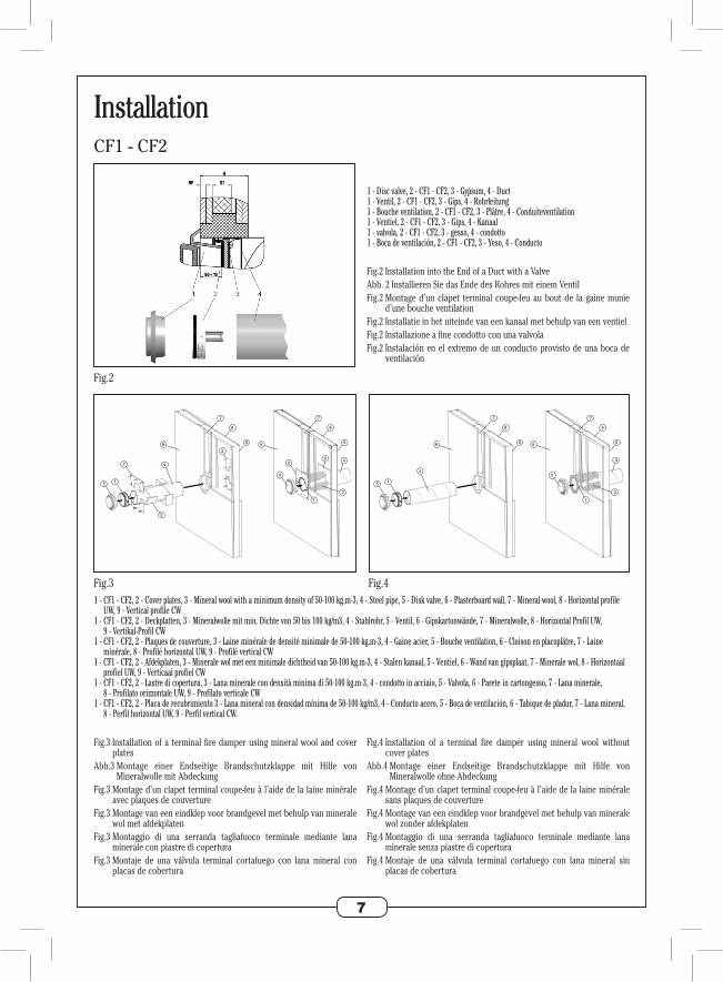
1 - Disc valve, 2 - CF1 - CF2, 3 - Gypsum, 4 - Duct1 - Ventil, 2 - CF1 - CF2, 3 - Gips, 4 - Rohrleitung1 - Bouche ventilation, 2 - CF1 - CF2, 3 - Plâtre, 4 - Conduiteventilation1 - Ventiel, 2 - CF1 - CF2, 3 - Gips, 4 - Kanaal1 - valvola, 2 - CF1 - CF2, 3 - gesso, 4 - condotto 1 - Boca de ventilación, 2 - CF1 - CF2, 3 - Yeso, 4 - Conducto
Fig.2 Installation into the End of a Duct with a ValveAbb. 2 Installieren Sie das Ende des Rohres mit einem VentilFig.2 Montage d’un clapet terminal coupe-feu au bout de la gaine munie
d’une bouche ventilationFig.2 Installatie in het uiteinde van een kanaal met behulp van een ventielFig.2 Installazione a fine condotto con una valvolaFig.2 Instalación en el extremo de un conducto provisto de una boca de
ventilación
Fig.3 Installation of a terminal fire damper using mineral wool and cover plates
Abb.3 Montage einer Endseitige Brandschutzklappe mit Hilfe von Mineralwolle mit Abdeckung
Fig.3 Montage d’un clapet terminal coupe-feu à l’aide de la laine minérale avec plaques de couverture
Fig.3 Montage van een eindklep voor brandgevel met behulp van minerale wol met afdekplaten
Fig.3 Montaggio di una serranda tagliafuoco terminale mediante lana minerale con piastre di copertura
Fig.3 Montaje de una válvula terminal cortafuego con lana mineral con placas de cobertura
Fig.4 Installation of a terminal fire damper using mineral wool without cover plates
Abb.4 Montage einer Endseitige Brandschutzklappe mit Hilfe von Mineralwolle ohne Abdeckung
Fig.4 Montage d’un clapet terminal coupe-feu à l’aide de la laine minérale sans plaques de couverture
Fig.4 Montage van een eindklep voor brandgevel met behulp van minerale wol zonder afdekplaten
Fig.4 Montaggio di una serranda tagliafuoco terminale mediante lana minerale senza piastre di copertura
Fig.4 Montaje de una válvula terminal cortafuego con lana mineral sin placas de cobertura
1 - CF1 - CF2, 2 - Cover plates, 3 - Mineral wool with a minimum density of 50-100 kg.m-3, 4 - Steel pipe, 5 - Disk valve, 6 - Plasterboard wall, 7 - Mineral wool, 8 - Horizontal profile UW, 9 - Vertical profile CW
1 - CF1 - CF2, 2 - Deckplatten, 3 - Mineralwolle mit min. Dichte von 50 bis 100 kg/m3, 4 - Stahlrohr, 5 - Ventil, 6 - Gipskartonwände, 7 - Mineralwolle, 8 - Horizontal Profil UW, 9 - Vertikal-Profil CW
1 - CF1 - CF2, 2 - Plaques de couverture, 3 - Laine minérale de densité minimale de 50-100 kg.m-3, 4 - Gaine acier, 5 - Bouche ventilation, 6 - Cloison en placoplâtre, 7 - Laine minérale, 8 - Profilé horizontal UW, 9 - Profilé vertical CW
1 - CF1 - CF2, 2 - Afdekplaten, 3 - Minerale wol met een minimale dichtheid van 50-100 kg.m-3, 4 - Stalen kanaal, 5 - Ventiel, 6 - Wand van gipsplaat, 7 - Minerale wol, 8 - Horizontaal profiel UW, 9 - Verticaal profiel CW
1 - CF1 - CF2, 2 - Lastre di copertura, 3 - Lana minerale con densità minima di 50-100 kg.m-3, 4 - condotto in acciaio, 5 - Valvola, 6 - Parete in cartongesso, 7 - Lana minerale, 8 - Profilato orizzontale UW, 9 - Profilato verticale CW
1 - CF1 - CF2, 2 - Placa de recubrimiento 3 - Lana mineral con densidad mínima de 50-100 kg/m3, 4 - Conducto acero, 5 - Boca de ventilación, 6 - Tabique de pladur, 7 - Lana mineral, 8 - Perfil horizontal UW, 9 - Perfil vertical CW.
5 1
4
6 9
8
7
5
1
4
6 9
8
7
3
5 1
2
2
4
3
6 9
8
7
5
1
22 4
6 9
8
7
3
CF1 - CF2
Fig.2
Fig.3 Fig.4

8
1 - Press bath detent springs, 2 - Open the blades into a parallel position, 3 - Put on the thermal fuse link
1 - Drücken die beiden Arretierfedern, 2 - Offnen Briefe an die parallele Position, 3 - Dritte Ersetzen Sie die Thermosicherung
1 - Poussez deux ressorts de détente, 2 - Mettez les lames en position horizontale, 3 - Insérez le fusible thermique
1 - Druk beide palveren in, 2 - Open de bladen in een parallel positie, 3 - Plaats de thermische smeltlood
1 - Sbloccare entrambe le molle di arresto, 2 - Aprire le alette in posizione parallela, 3 - Inserire il fusibile
1 - Empujar los 2 muelles de disparo, 2 – Poner las lamas en posición horizontal, 3 - Insertar el fusible térmico
Fig.5 Adjusting the terminal fire damper into Opera ting PositionAbb. 5 Stellung der Endseitige Brandschutzklappe in die geoffnete PositionFig.5 Réarmement d’un clapet terminal coupe-feuFig.5 lnstellen van de eindklep voor brandgevel in de definitieve positieFig.5 Regolazione della serranda tagliafuoco terminale in posizione di funzionamentoFig.5 Rearme del válvula terminal cortafuego
Fig.6 Connection of the end switchAbb. 6 Beteiligung der EndschalterFig.6 Branchement d’un interrupteur fin de courseFig.6 Aansluiten van de eindschakelaarFig.6 Collegamento del finecorsaFig.6 Conexión de un contacto final de carrera.
1 -black wire 1 -zwarte draad 2 CLOSED indicator -blue wire 2 GESLOTEN indicator -blauwe draad 3 OPEN indicator -grey wire 3 OPEN indicator -grijze draad
1 -schwarzer Kabel 1 -terra fila nera 2 Anzeige GESCHLOSSEN -blauer Kabel 2 segnalazione di chiusura -fila blu 3 Anzeige GEOFFNET -grau er Kabel 3 segnalazione di apertura -fila grigio
1 -fil noir 1 -cable negro2 Indication de position FERMÉ -fil bleu 2 Indicación de posición CERRADO -cable azul3 Indication de position OUVERT -fil gris 3 indicación de posición ABIERTO -cable gris
ActivationCF1 - CF2
Fig.5
Fig.6
9
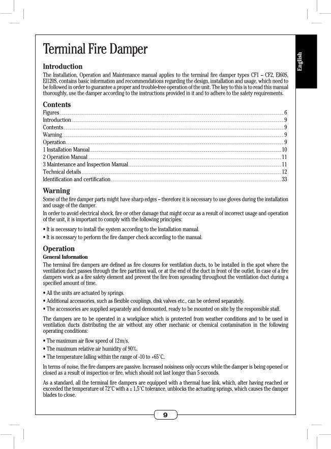
IntroductionThe Installation, Operation and Maintenance manual applies to the terminal fire damper types CF1 – CF2, EI60S, EI120S, contains basic information and recommendations regarding the design, installation and usage, which need to be followed in order to guarantee a proper and trouble-free operation of the unit. The key to this is to read this manual thoroughly, use the damper according to the instructions provided in it and to adhere to the safety requirements.
ContentsFigures.............................................................................................................................................................................................................................................................................................................................................6Introduction ...........................................................................................................................................................................................................................................................................................................................9Contents .......................................................................................................................................................................................................................................................................................................................................9Warning .........................................................................................................................................................................................................................................................................................................................................9Operation ...................................................................................................................................................................................................................................................................................................................................91 Installation Manual ............................................................................................................................................................................................................................................................................................102 Operation Manual ...............................................................................................................................................................................................................................................................................................113 Maintenance and Inspection Manual ...................................................................................................................................................................................................................................11Technical details ........................................................................................................................................................................................................................................................................................................12Identification and certification .............................................................................................................................................................................................................................................................33
WarningSome of the fire damper parts might have sharp edges – therefore it is necessary to use gloves during the installation and usage of the damper. In order to avoid electrical shock, fire or other damage that might occur as a result of incorrect usage and operation of the unit, it is important to comply with the following principles:
• It is necessary to install the system according to the Installation manual.• It is necessary to perform the fire damper check according to the manual.
OperationGeneral Information
The terminal fire dampers are defined as fire closures for ventilation ducts, to be installed in the spot where the ventilation duct passes through the fire partition wall, or at the end of the duct in front of the outlet. In case of a fire dampers work as a fire safety element and prevent the fire from spreading throughout the ventilation duct during a specified amount of time.
• All the units are actuated by springs.• Additional accessories, such as flexible couplings, disk valves etc., can be ordered separately.• The accessories are supplied separately and demounted, ready to be mounted on site by the responsible staff.
The dampers are to be operated in a workplace which is protected from weather conditions and to be used in ventilation ducts distributing the air without any other mechanic or chemical contamination in the following operating conditions:
• The maximum air flow speed of 12 m/s.• The maximum relative air humidity of 90%.• The temperature falling within the range of -10 to +65°C.
In terms of noise, the fire dampers are passive. Increased noisiness only occurs while the damper is being opened or closed as a result of inspection or fire, which should not last longer than 5 seconds.
As a standard, all the terminal fire dampers are equipped with a thermal fuse link, which, after having reached or exceeded the temperature of 72°C with a ± 1,5°C tolerance, unblocks the actuating springs, which causes the damper blades to close.
Terminal Fire Damper
Engl
ish
10
Terminal Fire Damper1 Installation Manual• The terminal fire dampers are installed into the duct, either in the place where the fire-proof wall is, or at the end
of the duct in front of an air valve or a similar outlet. (The terminal fir dampers are installed into the duct, either in the place where the fire-proof wall is into a transversal duct, or at the end of the duct in front of an air valve or a similar outlet.)
• The pitch between the ducts and the fire dampers must be at least 200 mm, according to the EN 1366-2 regulation.• According to the EN 1366-2 regulation, there must be at least a 75 mm gap between the wall and the ductwork with
the fire damper.• The fire damper is embedded into the fire partition construction pipe in such a way that when the damper blades
are in the CLOSE position, they will be entirely situated inside the wall.• The damper can be embedded into a wall or a ceiling with a minimum thickness according to the EN 1366-2
regulation for the respective fire resistance class.• All the dampers can be installed with a horizontal or a vertical blade axis.
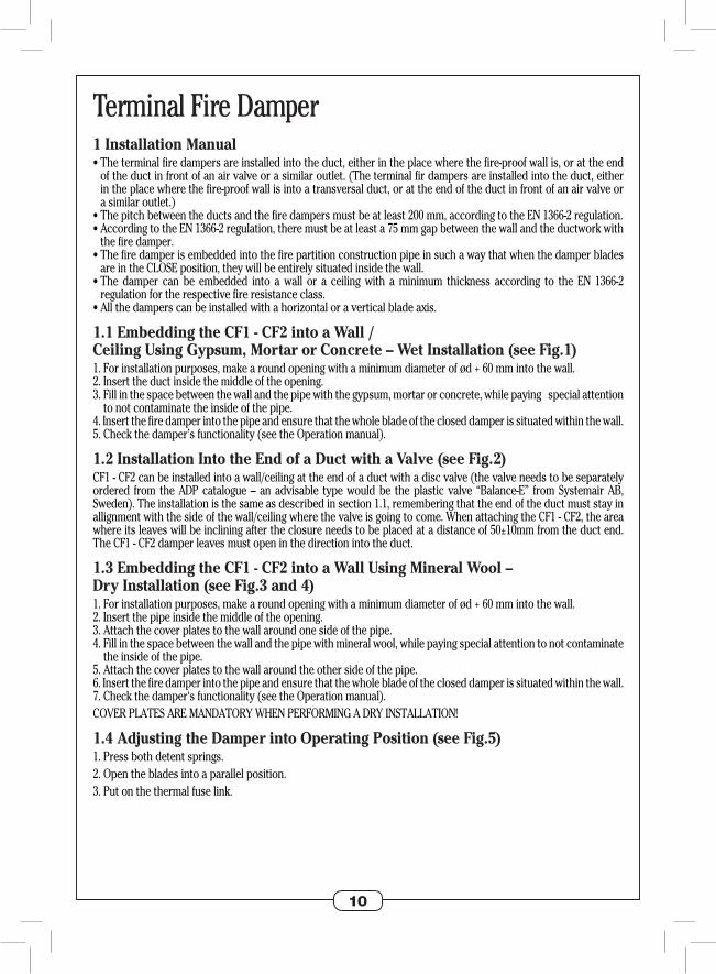
1.1 Embedding the CF1 - CF2 into a Wall / Ceiling Using Gypsum, Mortar or Concrete – Wet Installation (see Fig.1)1. For installation purposes, make a round opening with a minimum diameter of ød + 60 mm into the wall.2. Insert the duct inside the middle of the opening.3. Fill in the space between the wall and the pipe with the gypsum, mortar or concrete, while paying special attention
to not contaminate the inside of the pipe.4. Insert the fire damper into the pipe and ensure that the whole blade of the closed damper is situated within the wall.5. Check the damper’s functionality (see the Operation manual).
1.2 Installation Into the End of a Duct with a Valve (see Fig.2)CF1 - CF2 can be installed into a wall/ceiling at the end of a duct with a disc valve (the valve needs to be separately ordered from the ADP catalogue – an advisable type would be the plastic valve “Balance-E” from Systemair AB, Sweden). The installation is the same as described in section 1.1, remembering that the end of the duct must stay in allignment with the side of the wall/ceiling where the valve is going to come. When attaching the CF1 - CF2, the area where its leaves will be inclining after the closure needs to be placed at a distance of 50±10mm from the duct end. The CF1 - CF2 damper leaves must open in the direction into the duct.
1.3 Embedding the CF1 - CF2 into a Wall Using Mineral Wool – Dry Installation (see Fig.3 and 4)1. For installation purposes, make a round opening with a minimum diameter of ød + 60 mm into the wall.2. Insert the pipe inside the middle of the opening.3. Attach the cover plates to the wall around one side of the pipe.4. Fill in the space between the wall and the pipe with mineral wool, while paying special attention to not contaminate
the inside of the pipe.5. Attach the cover plates to the wall around the other side of the pipe.6. Insert the fire damper into the pipe and ensure that the whole blade of the closed damper is situated within the wall.7. Check the damper‘s functionality (see the Operation manual). COVER PLATES ARE MANDATORY WHEN PERFORMING A DRY INSTALLATION!
1.4 Adjusting the Damper into Operating Position (see Fig.5)1. Press both detent springs.2. Open the blades into a parallel position.3. Put on the thermal fuse link.
11
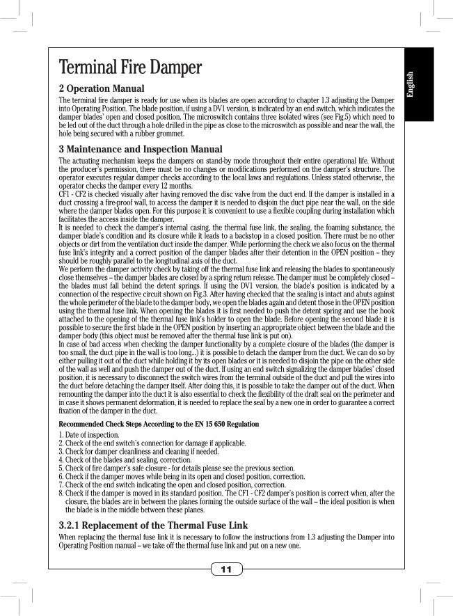
Terminal Fire Damper2 Operation ManualThe terminal fire damper is ready for use when its blades are open according to chapter 1.3 adjusting the Damper into Operating Position. The blade position, if using a DV1 version, is indicated by an end switch, which indicates the damper blades’ open and closed position. The microswitch contains three isolated wires (see Fig.5) which need to be led out of the duct through a hole drilled in the pipe as close to the microswitch as possible and near the wall, the hole being secured with a rubber grommet.
3 Maintenance and Inspection ManualThe actuating mechanism keeps the dampers on stand-by mode throughout their entire operational life. Without the producer’s permission, there must be no changes or modifications performed on the damper’s structure. The operator executes regular damper checks according to the local laws and regulations. Unless stated otherwise, the operator checks the damper every 12 months.CF1 - CF2 is checked visually after having removed the disc valve from the duct end. If the damper is installed in a duct crossing a fire-proof wall, to access the damper it is needed to disjoin the duct pipe near the wall, on the side where the damper blades open. For this purpose it is convenient to use a flexible coupling during installation which facilitates the access inside the damper.It is needed to check the damper’s internal casing, the thermal fuse link, the sealing, the foaming substance, the damper blade’s condition and its closure while it leads to a backstop in a closed position. There must be no other objects or dirt from the ventilation duct inside the damper. While performing the check we also focus on the thermal fuse link’s integrity and a correct position of the damper blades after their detention in the OPEN position – they should be roughly parallel to the longitudinal axis of the duct.We perform the damper activity check by taking off the thermal fuse link and releasing the blades to spontaneously close themselves – the damper blades are closed by a spring return release. The damper must be completely closed – the blades must fall behind the detent springs. If using the DV1 version, the blade’s position is indicated by a connection of the respective circuit shown on Fig.3. After having checked that the sealing is intact and abuts against the whole perimeter of the blade to the damper body, we open the blades again and detent those in the OPEN position using the thermal fuse link. When opening the blades it is first needed to push the detent spring and use the hook attached to the opening of the thermal fuse link’s holder to open the blade. Before opening the second blade it is possible to secure the first blade in the OPEN position by inserting an appropriate object between the blade and the damper body (this object must be removed after the thermal fuse link is put on).In case of bad access when checking the damper functionality by a complete closure of the blades (the damper is too small, the duct pipe in the wall is too long...) it is possible to detach the damper from the duct. We can do so by either pulling it out of the duct while holding it by its open blades or it is needed to disjoin the pipe on the other side of the wall as well and push the damper out of the duct. If using an end switch signalizing the damper blades’ closed position, it is necessary to disconnect the switch wires from the terminal outside of the duct and pull the wires into the duct before detaching the damper itself. After doing this, it is possible to take the damper out of the duct. When remounting the damper into the duct it is also essential to check the flexibility of the draft seal on the perimeter and in case it shows permanent deformation, it is needed to replace the seal by a new one in order to guarantee a correct fixation of the damper in the duct.
Recommended Check Steps According to the EN 15 650 Regulation
1. Date of inspection.2. Check of the end switch’s connection for damage if applicable.3. Check for damper cleanliness and cleaning if needed.4. Check of the blades and sealing, correction.5. Check of fire damper’s safe closure - for details please see the previous section.6. Check if the damper moves while being in its open and closed position, correction.7. Check of the end switch indicating the open and closed position, correction.8. Check if the damper is moved in its standard position. The CF1 - CF2 damper’s position is correct when, after the
closure, the blades are in between the planes forming the outside surface of the wall – the ideal position is when the blade is in the middle between these planes.
3.2.1 Replacement of the Thermal Fuse LinkWhen replacing the thermal fuse link it is necessary to follow the instructions from 1.3 adjusting the Damper into Operating Position manual – we take off the thermal fuse link and put on a new one.
Engl
ish
12
Technical details
Pressure loss
Dimensions (mm) - Weight (kg)
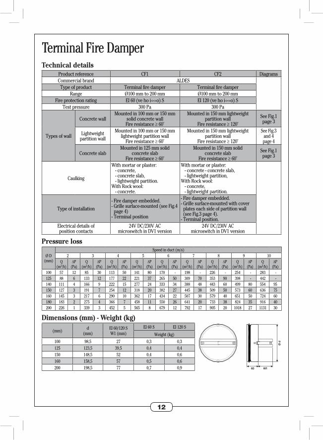
Product reference CF1 CF2 DiagramsCommercial brand ALDES
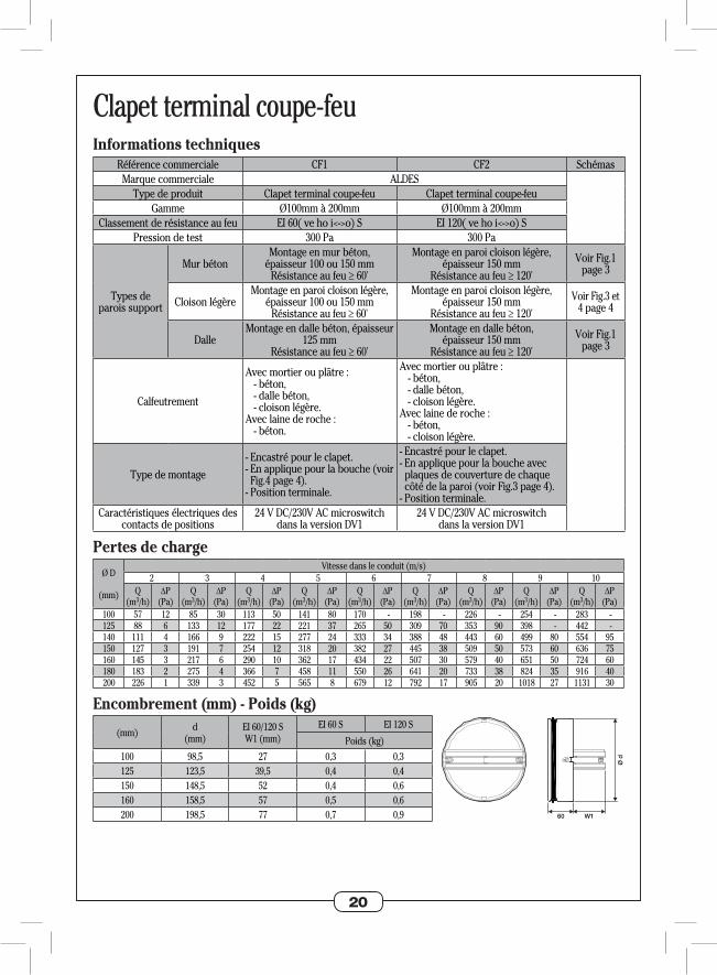
Type of product Terminal fire damper Terminal fire damperRange Ø100 mm to 200 mm Ø100 mm to 200 mm
Fire protection rating EI 60 (ve ho i<->o) S EI 120 (ve ho i<->o) STest pressure 300 Pa 300 Pa
Types of wall
Concrete wallMounted in 100 mm or 150 mm
solid concrete wallFire resistance ≥ 60’
Mounted in 150 mm lightweight partition wall
Fire resistance ≥ 120’
See Fig.1 page 3
Lightweight partition wall
Mounted in 100 mm or 150 mm lightweight partition wall
Fire resistance ≥ 60’
Mounted in 150 mm lightweight partition wall
Fire resistance ≥ 120’
See Fig.3 and 4 page 4
Concrete slabMounted in 125 mm solid
concrete slabFire resistance ≥ 60’
Mounted in 150 mm solid concrete slab
Fire resistance ≥ 60’
See Fig.1 page 3
Caulking
With mortar or plaster:- concrete,- concrete slab,- lightweight partition.
With Rock wool:- concrete.
With mortar or plaster:- concrete - concrete slab,- lightweight partition,
With Rock wool:- concrete, - lightweight partition.
Type of installation
- Fire damper embedded.- Grille surface-mounted (see Fig.4 page 4)
- Terminal position
- Fire damper embedded.- Grille surface-mounted with cover plates each side of partition wall (see Fig.3 page 4).
- Terminal position.Electrical details of position contacts
24V DC/230V AC microswitch in DV1 version
24V DC/230V AC microswitch in DV1 version
Ø D (mm)
Speed in duct (m/s)2 3 4 5 6 7 8 9 10
Q (m3/h)
∆P(Pa)
Q(m3/h)
∆P(Pa)
Q(m3/h)
∆P(Pa)
Q(m3/h)
∆P(Pa)
Q(m3/h)
∆P(Pa)
Q(m3/h)
∆P(Pa)
Q(m3/h)
∆P(Pa)
Q(m3/h)
∆P(Pa)
Q(m3/h)
∆P(Pa)
100 57 12 85 30 113 50 141 80 170 - 198 - 226 - 254 - 283 - 125 88 6 133 12 177 22 221 37 265 50 309 70 353 90 398 - 442 - 140 111 4 166 9 222 15 277 24 333 34 388 48 443 60 499 80 554 95150 127 3 191 7 254 12 318 20 382 27 445 38 509 50 573 60 636 75160 145 3 217 6 290 10 362 17 434 22 507 30 579 40 651 50 724 60180 183 2 275 4 366 7 458 11 550 26 641 20 733 38 824 35 916 40200 226 1 339 3 452 5 565 8 679 12 792 17 905 20 1018 27 1131 30
(mm) d (mm)
EI 60/120 S W1 (mm)
EI 60 S EI 120 S
Weight (kg)
100 98,5 27 0,3 0,3125 123,5 39,5 0,4 0,4150 148,5 52 0,4 0,6160 158,5 57 0,5 0,6200 198,5 77 0,7 0,9
Terminal Fire Damper
Ø d
60 W1
13
EinführungDie Installation, Bedienung und Kontrolle Einleitung betrifft der Endseitige Brandschutzklappen Type CF1 - CF2 EI60S, EI120S, enthält Grundinformationen und Empfehlungen für die Installation und Verwendung die sind zu beachten für Störungsfreier Betrieb der Brandsutzklappe. Der Schlüssel zur ordnungsgemäßen und sicheren Betrieb der Einheit ist bestens Vertrauen mit dieser Anleitung, die Verwendung von Klappen in Übereinstimmung mit den darin enthaltenen Anweisungen, und die Einhaltung der Sicherheitsanforderungen.
InhaltAbbildungen ....................................................................................................................................................................................................................................................................................................... 6Einführung ........................................................................................................................................................................................................................................................................................................ 13Inhalt ......................................................................................................................................................................................................................................................................................................................... 13Anmerkung ...................................................................................................................................................................................................................................................................................................... 13Der Betrieb ....................................................................................................................................................................................................................................................................................................... 131 Installationsanweisung .............................................................................................................................................................................................................................................................. 142 Hinweise zur Benutzung ......................................................................................................................................................................................................................................................... 153 Hinweise für Wartung und Revision ...................................................................................................................................................................................................................... 16Technische Informationen ..........................................................................................................................................................................................................................................................16Beschreibung und Zertifizierung ........................................................................................................................................................................................................................................33
AnmerkungDie Kanten von einigen Komponenten von Brandschutzklappen können knackig sein - so ist es notwendig, bei Installieren und Manipulation Handschuhe zu verwenden. Um einen elektrischen Schlag, Feuer oder andere Schäden verhindern, die aus fehlerhafter Verwendung und Betrieb der Einheit führen können, ist es wichtig, die folgenden Grundsätze zu beachten:
• Das System muss nach Installationsanweisungen installiert werden.• Überprüfen der Brandschutzklappe ist nach der Einleitung zu durchführen.
BetriebAllgemeine Informationen
Endseitige Brandschutzklappen sind wie Feuer Verschlüsse bezeichnet für Luftleitungen mit der Installation an der Stelle, wo das Rohr durch die Brandwand geht oder am Ende des Rohres vor dem Auslass/Ventil. Im Falle des Brandfall dienen die als Brandschutzeinheit und während einer vorgegebenen Zeitspanne verhindern Durchtritt von Feuer und Rauch durch den Lüftungskanal.
• Alle Geräte sind durch Federn gesteuert.• Zubehör wie flexible Kupplungen, Ventile und Deckplatten können separat bestellt werden.• Zubehör wird separat geliefert und vor Ort von Monteure fertig montiert wird.
Klappen sind so ausgelegt, in einem Umfeld, das von Witterung geschützt ist, um in den Luftrohrleitungen ohne zusätzliche mechanische oder chemische Zusätze für die folgenden Betriebsbedingungen eingesetzt zu werden und zu betreiben:
• Die maximale Luftgeschwindigkeit - 12 m/s.• Maximale relative Luftfeuchtigkeit - 90%.• Temperaturbereich von -10 bis +65°C.
Endseitige Brandschutzklappen sind passiv in Bezug auf Lärm. Erhöhtes Rauschen ist nur in weniger als 1 Sekunde auf manifestierte Schließen bei der Überprüfung oder Kontrolle der Brandschutzklappe.
Alle Endseitige Brandschutzklappen sind mit einer Thermosicherung ausgestattet, die bei Erreichen oder Überschreiten 72°C mit Toleranz von ± 1,5°C entriegelt die Schließfeder und die Blätter der Brandschutzklappen geschlossen werden.
Endseitige Brandschutzklappe
Deu
tsch
14
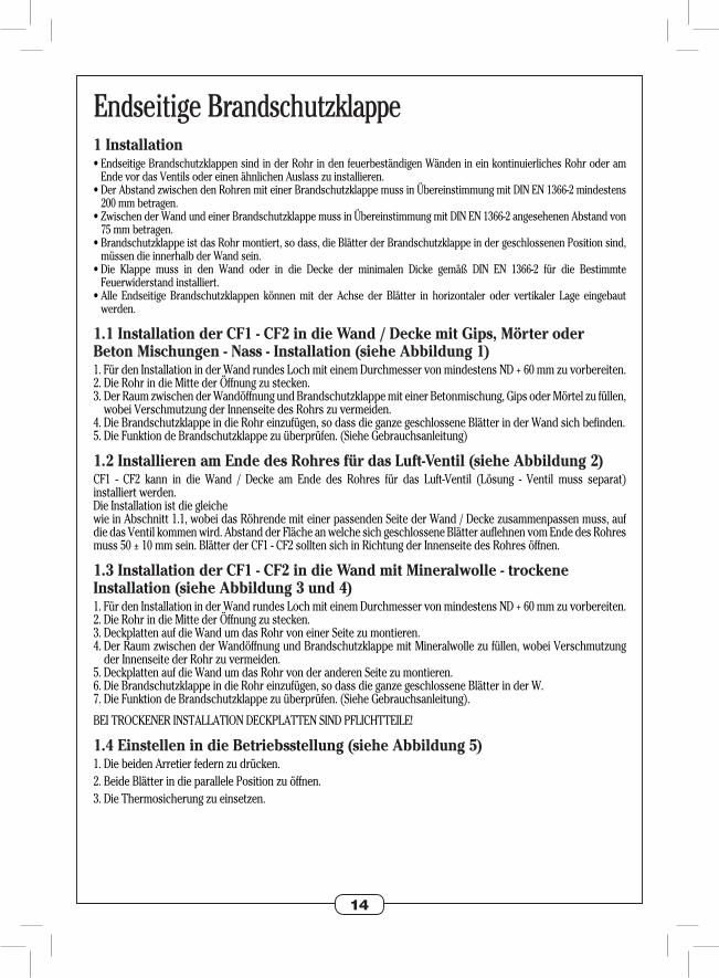
Endseitige Brandschutzklappe1 Installation• Endseitige Brandschutzklappen sind in der Rohr in den feuerbeständigen Wänden in ein kontinuierliches Rohr oder am
Ende vor das Ventils oder einen ähnlichen Auslass zu installieren.• Der Abstand zwischen den Rohren mit einer Brandschutzklappe muss in Übereinstimmung mit DIN EN 1366-2 mindestens
200 mm betragen.• Zwischen der Wand und einer Brandschutzklappe muss in Übereinstimmung mit DIN EN 1366-2 angesehenen Abstand von
75 mm betragen.• Brandschutzklappe ist das Rohr montiert, so dass, die Blätter der Brandschutzklappe in der geschlossenen Position sind,
müssen die innerhalb der Wand sein.• Die Klappe muss in den Wand oder in die Decke der minimalen Dicke gemäß DIN EN 1366-2 für die Bestimmte
Feuerwiderstand installiert.• Alle Endseitige Brandschutzklappen können mit der Achse der Blätter in horizontaler oder vertikaler Lage eingebaut
werden.
1.1 Installation der CF1 - CF2 in die Wand / Decke mit Gips, Mörter oder Beton Mischungen - Nass - Installation (siehe Abbildung 1)1. Für den Installation in der Wand rundes Loch mit einem Durchmesser von mindestens ND + 60 mm zu vorbereiten.2. Die Rohr in die Mitte der Öffnung zu stecken.3. Der Raum zwischen der Wandöffnung und Brandschutzklappe mit einer Betonmischung, Gips oder Mörtel zu füllen,
wobei Verschmutzung der Innenseite des Rohrs zu vermeiden.4. Die Brandschutzklappe in die Rohr einzufügen, so dass die ganze geschlossene Blätter in der Wand sich befinden.5. Die Funktion de Brandschutzklappe zu überprüfen. (Siehe Gebrauchsanleitung)
1.2 Installieren am Ende des Rohres für das Luft-Ventil (siehe Abbildung 2)CF1 - CF2 kann in die Wand / Decke am Ende des Rohres für das Luft-Ventil (Lösung - Ventil muss separat) installiert werden.Die Installation ist die gleichewie in Abschnitt 1.1, wobei das Röhrende mit einer passenden Seite der Wand / Decke zusammenpassen muss, auf die das Ventil kommen wird. Abstand der Fläche an welche sich geschlossene Blätter auflehnen vom Ende des Rohres muss 50 ± 10 mm sein. Blätter der CF1 - CF2 sollten sich in Richtung der Innenseite des Rohres öffnen.
1.3 Installation der CF1 - CF2 in die Wand mit Mineralwolle - trockene Installation (siehe Abbildung 3 und 4)1. Für den Installation in der Wand rundes Loch mit einem Durchmesser von mindestens ND + 60 mm zu vorbereiten.2. Die Rohr in die Mitte der Öffnung zu stecken.3. Deckplatten auf die Wand um das Rohr von einer Seite zu montieren.4. Der Raum zwischen der Wandöffnung und Brandschutzklappe mit Mineralwolle zu füllen, wobei Verschmutzung
der Innenseite der Rohr zu vermeiden.5. Deckplatten auf die Wand um das Rohr von der anderen Seite zu montieren.6. Die Brandschutzklappe in die Rohr einzufügen, so dass die ganze geschlossene Blätter in der W.7. Die Funktion de Brandschutzklappe zu überprüfen. (Siehe Gebrauchsanleitung).
BEI TROCKENER INSTALLATION DECKPLATTEN SIND PFLICHTTEILE!
1.4 Einstellen in die Betriebsstellung (siehe Abbildung 5)1. Die beiden Arretier federn zu drücken.2. Beide Blätter in die parallele Position zu öffnen.3. Die Thermosicherung zu einsetzen.
15
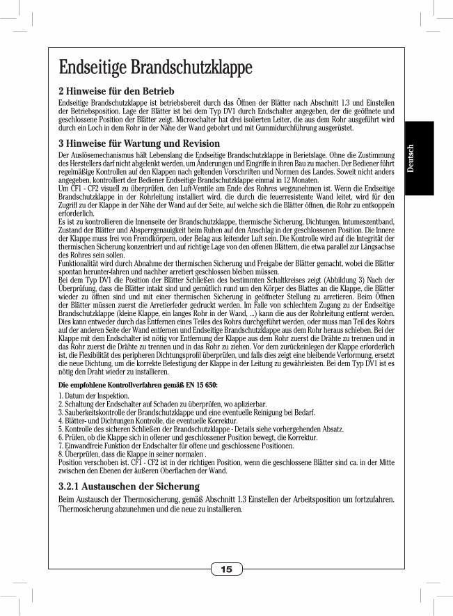
Endseitige Brandschutzklappe2 Hinweise für den BetriebEndseitige Brandschutzklappe ist betriebsbereit durch das Öffnen der Blätter nach Abschnitt 1.3 und Einstellen der Betriebsposition. Lage der Blätter ist bei dem Typ DV1 durch Endschalter angegeben, der die geöffnete und geschlossene Position der Blätter zeigt. Microschalter hat drei isolierten Leiter, die aus dem Rohr ausgeführt wird durch ein Loch in dem Rohr in der Nähe der Wand gebohrt und mit Gummidurchführung ausgerüstet.
3 Hinweise für Wartung und RevisionDer Auslösemechanismus hält Lebenslang die Endseitige Brandschutzklappe in Berietslage. Ohne die Zustimmung des Herstellers darf nicht abgelenkt werden, um Änderungen und Eingriffe in ihren Bau zu machen. Der Bediener führt regelmäßige Kontrollen auf den Klappen nach geltenden Vorschriften und Normen des Landes. Soweit nicht anders angegeben, kontrolliert der Bediener Endseitige Brandschutzklappe einmal in 12 Monaten.Um CF1 - CF2 visuell zu überprüfen, den Luft-Ventile am Ende des Rohres wegzunehmen ist. Wenn die Endseitige Brandschutzklappe in der Rohrleitung installiert wird, die durch die feuerresistente Wand leitet, wird für den Zugriff zu der Klappe in der Nähe der Wand auf der Seite, auf welche sich die Blätter öffnen, die Rohr zu entkoppeln erforderlich.Es ist zu kontrollieren die Innenseite der Brandschutzklappe, thermische Sicherung, Dichtungen, Intumeszentband, Zustand der Blätter und Absperrgenauigkeit beim Ruhen auf den Anschlag in der geschlossenen Position. Die Innere der Klappe muss frei von Fremdkörpern, oder Belag aus leitender Luft sein. Die Kontrolle wird auf die Integrität der thermischen Sicherung konzentriert und auf richtige Lage von den offenen Blättern, die etwa parallel zur Längsachse des Rohres sein sollen.Funktionalität wird durch Abnahme der thermischen Sicherung und Freigabe der Blätter gemacht, wobei die Blätter spontan herunter-fahren und nachher arretiert geschlossen bleiben müssen.Bei dem Typ DV1 die Position der Blätter Schließen des bestimmten Schaltkreises zeigt (Abbildung 3) Nach der Überprüfung, dass die Blätter intakt sind und gemütlich rund um den Körper des Blattes an die Klappe, die Blätter wieder zu öffnen sind und mit einer thermischen Sicherung in geöffneter Stellung zu arretieren. Beim Öffnen der Blätter müssen zuerst die Arretierfeder gedruckt werden. Im Falle von schlechtem Zugang zu der Endseitige Brandschutzklappe (kleine Klappe, ein langes Rohr in der Wand, ...) kann die aus der Rohrleitung entfernt werden. Dies kann entweder durch das Entfernen eines Teiles des Rohrs durchgeführt werden, oder muss man Teil des Rohrs auf der anderen Seite der Wand entfernen und Endseitige Brandschutzklappe aus dem Rohr heraus schieben. Bei der Klappe mit dem Endschalter ist nötig vor Entfernung der Klappe aus dem Rohr zuerst die Drähte zu trennen und in das Rohr zuerst die Drähte zu trennen und in das Rohr zu ziehen. Vor dem zurückeinlegen der Klappe erforderlich ist, die Flexibilität des peripheren Dichtungsprofil überprüfen, und falls dies zeigt eine bleibende Verformung, ersetzt die neue Dichtung, um die korrekte Befestigung der Klappe in der Leitung zu gewährleisten. Bei dem Typ DV1 ist es nötig den Draht wieder zu installieren.
Die empfohlene Kontrollverfahren gemäß EN 15 650:
1. Datum der Inspektion.2. Schaltung der Endschalter auf Schaden zu überprüfen, wo aplizierbar.3. Sauberkeitskontrolle der Brandschutzklappe und eine eventuelle Reinigung bei Bedarf.4. Blätter- und Dichtungen Kontrolle, die eventuelle Korrektur.5. Kontrolle des sicheren Schließen der Brandschutzklappe - Details siehe vorhergehenden Absatz.6. Prüfen, ob die Klappe sich in offener und geschlossener Position bewegt, die Korrektur.7. Einwandfreie Funktion der Endschalter für offene und geschlossene Positionen.8. Überprüfen, dass die Klappe in seiner normalen .Position verschoben ist. CF1 - CF2 ist in der richtigen Position, wenn die geschlossene Blätter sind ca. in der Mitte zwischen den Ebenen der äußeren Oberflachen der Wand.
3.2.1 Austauschen der SicherungBeim Austausch der Thermosicherung, gemäß Abschnitt 1.3 Einstellen der Arbeitsposition um fortzufahren. Thermosicherung abzunehmen und die neue zu installieren.
Deu
tsch
16
Technische Informationen
Druckverlust
Maße (mm) - Gewicht (kg)
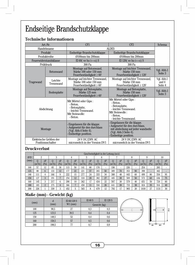
Art.-Nr. CF1 CF2 SchemaHandelsname ALDES
Produkt Endseitige Brandschutzklappe Endseitige BrandschutzklappeProduktreihe Ø100mm bis 200mm Ø100mm bis 200mm
Feuerwiderstandsklasse EI 60( ve ho i<->o) S EI 120( ve ho i<->o) SPrüfdruck 300 Pa 300 Pa
Tragewand
BetonwandMontage auf Betonwand, Stärke 100 oder 150 mm Feuerbeständigkeit ≥ 60'
Montage auf leichter Trennwand, Stärke 150 mm
Feuerbeständigkeit ≥ 120'
Vgl. Abb.1 Seite 3
Leichte Trennwand
Montage auf leichter Trennwand, Stärke 100 oder 150 mm Feuerbeständigkeit ≥ 60'
Montage auf leichter Trennwand, Stärke 150 mm
Feuerbeständigkeit ≥ 120'
Vgl. Abb.1 und 4
Seite 4
BodenplatteMontage auf Betonplatte,
Stärke 125 mm Feuerbeständigkeit ≥ 60'
Montage auf Betonplatte, Stärke 150 mm
Feuerbeständigkeit ≥ 120'
Vgl. Abb.1 Seite 3
Abdichtung
Mit Mörtel oder Gips :- Beton, - Betonplatte, - leichte Trennwand.
Mit Steinwolle:- Beton.
Mit Mörtel oder Gips :- Beton, - Betonplatte, - leichte Trennwand.
Mit Steinwolle :- Beton, - leichte Trennwand.
Montage
- Eingelassen für die klappe.- Aufgesetzt für den durchlass (Vgl. Abb.4 Seite 4).
- Endseitige position.
- Eingelassen für die klappe.- Aufgesetzt für den durchlass, mit abdeckung auf jeder wandseite (Vgl. Abb.3 Seite 4).
- Endseitige position.Elektrische Größen der
Positionsschalter24 V DC/230V AC
microswitch in der Version DV124 V DC/230V AC
microswitch in der Version DV1
Ø D (mm)
Geschwindigkeit in der Leitung (m/s)2 3 4 5 6 7 8 9 10
Q (m3/h)
∆P(Pa)
Q(m3/h)
∆P(Pa)
Q(m3/h)
∆P(Pa)
Q(m3/h)
∆P(Pa)
Q(m3/h)
∆P(Pa)
Q(m3/h)
∆P(Pa)
Q(m3/h)
∆P(Pa)
Q(m3/h)
∆P(Pa)
Q(m3/h)
∆P(Pa)
100 57 12 85 30 113 50 141 80 170 - 198 - 226 - 254 - 283 - 125 88 6 133 12 177 22 221 37 265 50 309 70 353 90 398 - 442 - 140 111 4 166 9 222 15 277 24 333 34 388 48 443 60 499 80 554 95150 127 3 191 7 254 12 318 20 382 27 445 38 509 50 573 60 636 75160 145 3 217 6 290 10 362 17 434 22 507 30 579 40 651 50 724 60180 183 2 275 4 366 7 458 11 550 26 641 20 733 38 824 35 916 40200 226 1 339 3 452 5 565 8 679 12 792 17 905 20 1018 27 1131 30
(mm) d (mm)
EI 60/120 S W1 (mm)
EI 60 S EI 120 S
Gewicht (kg)
100 98,5 27 0,3 0,3125 123,5 39,5 0,4 0,4150 148,5 52 0,4 0,6160 158,5 57 0,5 0,6200 198,5 77 0,7 0,9
Endseitige Brandschutzklappe
Ø d
60 W1
17
IntroductionCe manuel d’installation, d’exploitation et de contrôle concerne tous clapets terminaux coupe-feu type CF1-CF2, EI60S, EI120S. Afin de garantir un fonctionnement correct et fiable de l’unité, respectez les consignes et recommandations indiquées dans ce manuel. Pour assurer un bon fonctionnement de l’unité, vous êtes tenus de prendre connaissance des instructions citées dans ce manuel et d’utiliser le clapet terminal coupe-feu conformément à ces dernières tout en respectant les consignes de sécurité.
Table des matièresFigure..................................................................................................................................................................................................................................................................................................................... 6Introduction ............................................................................................................................................................................................................................................................................................. 17Table des matières ......................................................................................................................................................................................................................................................................... 17Mise en garde ......................................................................................................................................................................................................................................................................................... 17Exploitation ............................................................................................................................................................................................................................................................................................... 171 Consignes d’installation ..................................................................................................................................................................................................................................................... 182 Consignes d’exploitation ................................................................................................................................................................................................................................................... 183 Entretien et contrôles ............................................................................................................................................................................................................................................................ 19Informations techniques ...........................................................................................................................................................................................................................................................20Identification et certification ...............................................................................................................................................................................................................................................33
Mise en gardeCertaines parties aigues du clapet terminal coupe-feu sont susceptibles de causer une blessure. Afin d’éviter ce risque, utilisez les gants lors de la manipulation avec le clapet terminal coupe-feu. Pour éviter le risque d’électrocution, d’incendie ou d’autres dangers susceptibles de se produire par suite d’une utilisation inappropriée de l’unité, il faut respecter les consignes suivantes :
• Installer le système conformément au manuel d’installation.• Réaliser les contrôles du clapet terminal coupe-feu conformément au manuel.
ExploitationInformations généralesLes clapets terminaux coupe-feu sont des dispositifs d’obturation installés dans les conduites de ventilation, plus précisément aux traversées des cloisons coupe-feu ou aux bouts des conduites situés dans les murs, devant la bouche. En cas d’incendie, les clapets terminaux coupe-feu constituent un élément de sécurité résistant au feu. Au cours d’une période de temps prescrite, les clapets terminaux coupe-feu empêchent au feu de se répandre par les conduites.
• Chaque clapet terminal est fermé par la force des ressorts de détente.• Les accessoires comme par exemple les raccords flexibles, bouches ventilation etc. peuvent être commandés
séparément.• Les accessoires sont livrés séparément et en état désassemblé. L’assemblage et l’installation est assurée par des
techniciens sur site.
Les clapets terminaux coupe-feu sont destinés à une application aux sites protégés de vent. Elles ne peuvent être installées que dans les conduites de ventilation distributrices de l’air sans additifs mécaniques ou chimiques en respectant les conditions d’exploitation suivantes :
• Vitesse maximale de circulation de l’air – 12 m/s.• Humidité relative de l’air - 90 %.• Gamme de température de -10 jusqu’au +65 °C.
Les clapets terminaux coupe-feu ne produisent pas de bruit important. Une marche bruyante se manifeste pendant une période de temps qui ne dépasse pas 5 secondes, lors de l’ouverture ou de fermeture causée par un déclenchement d’essai ou par l’incendie.De façon standard, chaque clapet terminal coupe-feu est équipé d’un fusible thermique susceptible d’être déclenché par toute température égale ou supérieure à 72 °C (avec un écart de ± 1,5 °C). Le fusible fait débloquer les ressorts de détente qui ferment les lames du clapet terminal coupe-feu.
Clapet terminal coupe-feu
Fran
çais
18
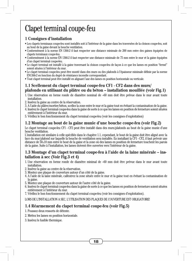
Clapet terminal coupe-feu1 Consignes d’installation• Les clapets terminaux coupe-feu sont installés soit à l’intérieur de la gaine dans les traversées de la cloison coupe-feu, soit
au bout de la gaine devant la bouche ventilation.• Conformément à la norme EN 1366-2 il faut respecter une distance minimale de 200 mm entre des gaines équipées de
clapets terminaux coupe-feu.• Conformément à la norme EN 1366-2 il faut respecter une distance minimale de 75 mm entre le mur et la gaine équipées
d’un clapet terminal coupe-feu.• Le clapet terminal est installé à la gaine traversant la cloison coupe-feu de façon à ce que les lames en position “fermé”
soient situées à l’intérieur du mur.• Le clapet terminal coupe-feu peut être monté dans des murs ou des plafonds à l’épaisseur minimale définie par la norme
EN1366-2 en fonction du degré de résistance incendie correspondant.• Tout clapet terminal peut être installé en alignant l’axe des lames en position horizontale ou verticale.
1.1 Scellement du clapet terminal coupe-feu CF1 - CF2 dans des murs/ plafonds en utilisant du plâtre ou du béton – installation mouillée (voir Fig.1)1. Une réservation en forme ronde de diamètre nominal de +60 mm doit être prévue dans le mur avant toute
installation.2. Insérez la gaine au centre de la réservation.3. A l’aide du plâtre/mortier/béton, scellez la zone entre le mur et la gaine tout en évitant la contamination de la gaine.4. Insérez le clapet terminal coupe-feu dans la gaine de sorte à ce que les lames en position de fermeture soient situées
entièrement à l’intérieur du mur.5. Vérifiez le bon fonctionnement du clapet terminal coupe-feu (voir les consignes d’exploitation)
1.2 Montage au bout de la gaine munie d’une bouche coupe-feu (voir Fig.2)Le clapet terminal coupe-feu CF1 - CF2 peut être installé dans des murs/plafonds au bout de la gaine munie d’une bouche ventilation.L’installation est similaire à celle spécifiée dans le chapitre 1.1, cependant, le bout de la gaine doit être aligné avec la face du mur/plafond sur laquelle la bouche de ventilation sera installée. En installant la CF1 - CF2, il faut prévoir une distance de 50±10 mm entre le bout de la gaine et la zone où des lames en position de fermeture touchent les parois de la gaine. Suite à l’installation, les lames doivent être ouvertes vers l’intérieur de la gaine.
1.3 Montage d’un clapet terminal coupe-feu à l’aide de la laine minérale – ins-tallation à sec (Voir Fig.3 et 4)1. Une réservation en forme ronde de diamètre minimal de +60 mm doit être prévue dans le mur avant toute
installation.2. Insérez la gaine au centre de la réservation.3. Montez une plaque de couverture autour d’un côté de la gaine.4. A l’aide de la laine minérale, calfeutrez la zone située entre le mur et la gaine tout en évitant la contamination de
la gaine.5. Montez une plaque de couverture autour de l’autre côté de la gaine.6. Insérez le clapet terminal coupe-feu dans la gaine de sorte à ce que les lames en position de fermeture soient situées
entièrement à l’intérieur du mur.7. Vérifiez le bon fonctionnement du clapet terminal coupe-feu (voir les consignes d’exploitation).
LORS DE L’INSTALLATION A SEC, L’UTILISATION DES PLAQUES DE COUVERTURE EST OBLIGATOIRE!
1.4 Réarmement du clapet terminal coupe-feu (voir Fig.5)1. Poussez deux ressorts de détente.2. Mettez les lames en position horizontale.3. Insérez le fusible thermique.

19
Clapet terminal coupe-feu2 Consignes d’utilisationLe réarmement du clapet terminal coupe-feu se réalise par l’ouverture des lames conformément aux consignes spécifiées dans le chapitre 1.3. (Réarmement du clapet terminal coupe-feu). Si vous utilisez le type DV1, la position d’ouverture ou de fermeture des lames est signalée par une ouverture dans la gaine percée aussi proche que possible du microrupteur et de la paroi. Cette ouverture doit être munie d’un passe-câble en caoutchouc.
3 Consignes d’entretien et de contrôleLe dispositif de déclenchement maintient les lames en position d’attente pendant toute la durée de vie. Aucune modification ni intervention sur les clapets terminaux coupe-feu ne peut être effectuée sans un accord préalable du producteur. L’exploitant est tenu de réaliser les contrôles réguliers des clapets terminaux coupe-feu conformément à la réglementation et normes locaux en vigueur. Sauf indication contraire, un contrôle doit être réalisé tous les 12 mois.Le contrôle de la CF1 - CF2 se fait visuellement, suite au démontage de la bouche de ventilation du bout de la gaine. Si la cartouche de ventilation est installée à la gaine qui traverse la cloison coupe-feu, il est nécessaire de disjoindre la gaine à proximité de la paroi vers laquelle s’ouvrent les lames afin de faciliter l’accès du clapet terminal.Lors du contrôle on examine également le corps interne du clapet terminal coupe-feu, le fusible thermique, l’étanchéité la mousse, l’état de la lame et la précision de fermeture des lames pendant leur contact avec butée. Le corps interne du clapet terminal coupe-feu ne peut contenir aucun objet ni poussière apportée par les conduites de ventilation. L’intégrité du fusible thermique fait aussi l’objet du contrôle tout comme une position correcte des lames suite au réarmement (mise en position d’ouverture). La position des lames doit être presque parallèle avec l’axe longitudinal de la gaine. Afin de vérifier le bon fonctionnement du clapet terminal coupe-feu, il faut démonter le fusible thermique et déclencher les lames pour les faire fermer spontanément grâce à l’énergie des ressorts de rappel. Fermez complètement le clapet terminal coupe-feu de sorte à ce que les lames soient arrêtées devant les ressorts. Si vous utilisez le type DV1, la position de la lame est signalée par la connexion du circuit correspondant selon Fig.3. Avant de réarmer les lames et de remonter le fusible, il est nécessaire d’examiner l’état d‘étanchéité et de son adhésion homogène au périmètre de la gaine. Pour ouvrir les lames, poussez d’abord le ressort. Ensuite utilisez un crochet attaché à l’ouverture de porte-fusible pour ouvrir une lame. Avant d’ouvrir une autre lame, vous pouvez bloquer la première dans sa position d’attente en insérant un objet approprié entre la lame et le corps (n’oubliez pas d’enlever cet objet suite au montage du fusible). Afin de réaliser un essai de contrôle sur un clapet terminal coupe-feu difficilement accessible (à cause de petites dimensions, de la longueur de gaine de conduite etc.) effectué par la fermeture complète de ses lames, il est possible de faire sortir le clapet terminal coupe-feu en dehors de la gaine. Dans ce cas, il faut retirer le clapet terminal coupe-feu en saisisant les lames en position d’ouverture. Le cas échéant il faudrait disjoindre la gaine d’autre côté de la cloison coupe-feu et pousser le clapet terminal vers l’extérieur. En cas d’usage d’un interrupteur fin de course qui signale la fermeture des lames, avant de sortir le clapet terminal coupe-feu il faut commencer par débrancher les fils de la borne et les tirer vers l’intérieur de la gaine. Avant remontage du clapet terminal coupe-feu suite au contrôle, il est nécessaire d’examiner la flexibilité d’étanchéité autour du périmètre. Si une déformation permanente est constatée, il faut remplacer l’échantéité afin d’assurer une fixation correcte du clapet terminal de la gaine.
Procédé de contrôle recommandé par la norme EN 15 650 :
1. Marquez la date d’inspection.2. Inspectez le branchement de l’interrupteur fin de course, notamment les endroits qui risquent de subir une
détérioration.3. Examinez la propreté du clapet terminal coupe-feu et nettoyez-le, si nécessaire.4. Examinez l’état des lames et d’étanchéité, réalisez une correction si nécessaire.5. Vérifiez la position correcte des lames en état de fermeture (voir alinéa précédent pour les informations détaillées)6. Vérifiez le mouvement du clapet terminal coupe-feu en position d’ouverture et de fermeture, réalisez une correction
si nécessaire.7. Inspectez un bon fonctionnement de l’interrupteur fin de course en position d’ouverture et de fermeture, réalisez
une correction si nécessaire.8. Vérifiez si le clapet terminal coupe-feu se trouve dans la position stable. Le clapet terminal CF1- CF2 et dans une
position correcte si les lames, suite à leur fermeture, restent entre les plaines formées par les côtés externes des murs- une position idéale se trouve au milieu de ces deux plaines.
3.2.1 Echange d’un fusibleAfin d’échanger le fusible, il faut suivre les consignes mentionnées dans l’article 1.3. Pour mettre le clapet terminal en service, il faut démonter l’ancien fusible et insérer le nouveau.
Fran
çais
20
Informations techniques
Pertes de charge
Encombrement (mm) - Poids (kg)
Référence commerciale CF1 CF2 SchémasMarque commerciale ALDES
Type de produit Clapet terminal coupe-feu Clapet terminal coupe-feuGamme Ø100mm à 200mm Ø100mm à 200mm
Classement de résistance au feu EI 60( ve ho i<->o) S EI 120( ve ho i<->o) SPression de test 300 Pa 300 Pa
Types de parois support
Mur bétonMontage en mur béton,
épaisseur 100 ou 150 mm Résistance au feu ≥ 60'
Montage en paroi cloison légère, épaisseur 150 mm
Résistance au feu ≥ 120'
Voir Fig.1 page 3
Cloison légèreMontage en paroi cloison légère,
épaisseur 100 ou 150 mm Résistance au feu ≥ 60'
Montage en paroi cloison légère, épaisseur 150 mm
Résistance au feu ≥ 120'
Voir Fig.3 et 4 page 4
DalleMontage en dalle béton, épaisseur
125 mm Résistance au feu ≥ 60'
Montage en dalle béton, épaisseur 150 mm
Résistance au feu ≥ 120'
Voir Fig.1 page 3
Calfeutrement
Avec mortier ou plâtre : - béton, - dalle béton, - cloison légère.
Avec laine de roche : - béton.
Avec mortier ou plâtre : - béton, - dalle béton, - cloison légère.
Avec laine de roche : - béton, - cloison légère.
Type de montage
- Encastré pour le clapet. - En applique pour la bouche (voir Fig.4 page 4).
- Position terminale.
- Encastré pour le clapet. - En applique pour la bouche avec plaques de couverture de chaque côté de la paroi (voir Fig.3 page 4).
- Position terminale.Caractéristiques électriques des
contacts de positions24 V DC/230V AC microswitch
dans la version DV124 V DC/230V AC microswitch
dans la version DV1
Ø D
(mm)
Vitesse dans le conduit (m/s)2 3 4 5 6 7 8 9 10
Q (m3/h)
∆P(Pa)
Q(m3/h)
∆P(Pa)
Q(m3/h)
∆P(Pa)
Q(m3/h)
∆P(Pa)
Q(m3/h)
∆P(Pa)
Q(m3/h)
∆P(Pa)
Q(m3/h)
∆P(Pa)
Q(m3/h)
∆P(Pa)
Q(m3/h)
∆P(Pa)
100 57 12 85 30 113 50 141 80 170 - 198 - 226 - 254 - 283 - 125 88 6 133 12 177 22 221 37 265 50 309 70 353 90 398 - 442 - 140 111 4 166 9 222 15 277 24 333 34 388 48 443 60 499 80 554 95150 127 3 191 7 254 12 318 20 382 27 445 38 509 50 573 60 636 75160 145 3 217 6 290 10 362 17 434 22 507 30 579 40 651 50 724 60180 183 2 275 4 366 7 458 11 550 26 641 20 733 38 824 35 916 40200 226 1 339 3 452 5 565 8 679 12 792 17 905 20 1018 27 1131 30
Clapet terminal coupe-feu
(mm) d (mm)
EI 60/120 S W1 (mm)
EI 60 S EI 120 S
Poids (kg)
100 98,5 27 0,3 0,3125 123,5 39,5 0,4 0,4150 148,5 52 0,4 0,6160 158,5 57 0,5 0,6200 198,5 77 0,7 0,9
Ø d
60 W1
21
InleidingDeze Installatie-, Bedienings- en Onderhoudsvoorschriften hebben betrekking op Eindklep voor brandgevelpen typen CF1 - CF2, EI60S, EI120S, en bevatten basisinformatie en aanbevelingen over ontwerp, installatie en gebruik, die nageleefd moeten worden voor het correct en probleemloos functioneren van de brandklep. Lees daartoe deze voorschriften aandachtig door, gebruik de brandklep in overeenstemming met de voorschriften en leef alle veiligheidsvoorschriften na.
InhoudFiguren ............................................................................................................................................................................................................................................................................................................ 6Inleiding ..................................................................................................................................................................................................................................................................................................... 21Inhoud ......................................................................................................................................................................................................................................................................................................... 21Waarschuwing .................................................................................................................................................................................................................................................................................. 18Bediening ................................................................................................................................................................................................................................................................................................. 181 Installatievoorschrift ........................................................................................................................................................................................................................................................... 192 Bedieningsvoorschriften ............................................................................................................................................................................................................................................... 193 Onderhouds- en Inspectievoorschriften ................................................................................................................................................................................................... 19Technische gegevens ................................................................................................................................................................................................................................................................20Identificatie en certificatie...................................................................................................................................................................................................................................................33
WaarschuwingEen aantal onderdelen van de brandklep kunnen scherpe randen hebben - gebruik daarom handschoenen tijdens de installatie en het gebruik van de brandklep. Om elektrische schokken, brand of andere schade als gevolg van een onjuist gebruik en bediening van de brandklep te vermijden, is het belangrijk de volgende punten in acht te nemen:• Installeer het systeem altijd in overeenstemming met de Installatievoorschriften.• Voer altijd een controle van de brandklep uit in overeenstemming met de voorschriften.
BedieningAlgemene informatie
De Eindklep voor brandgevelpen zijn bedoeld als brandafsluiters voor ventilatiekanalen en moeten worden geïnstalleerd op de plek waar het kanaal door de brandscheidingswand gaat of aan het uiteinde van het kanaal voor het rooster. Bij een brand functioneren de kleppen als een brandveilig element en voorkomen gedurende een bepaalde periode, dat de brand zich door het ventilatiekanaal kan verspreiden.
• Alle eenheden worden geregeld met behulp van veren.• Extra accessoires, zoals flexibele koppelingen, ventielen, enz. kunnen afzonderlijk worden besteld.• De accessoires worden afzonderlijk en gedemonteerd geleverd en dienen ter plekke door gekwalificeerd personeel
te worden gemonteerd.
De brandkleppen mogen uitsluitend worden gebruikt op werkplekken die zijn afgeschermd tegen weersomstandigheden en in ventilatiekanalen die lucht verspreiden zonder enige vorm van mechanische of chemische verontreiniging in de volgende omstandigheden:
• Maximale luchtsnelheid 12 m/s.• Maximale relatieve luchtvochtigheid van 90%.• Temperaturen tussen -10 en +65 °C.In termen van geluid zijn de brandkleppen passief. Een verhoogd geluidsniveau treedt uitsluitend op als de brandklep wordt geopend of gesloten als gevolg van een inspectie of een brand en zou niet langer mogen aanhouden dan 5 seconden.
Alle Eindklep voor brandgevelpen worden standaard voorzien van een thermische smeltlood die de veren activeert en zodoende de klepbladen doet sluiten, in geval een temperatuur van 72 °C (met een speling van ± 1,5 °C) bereikt of overschreden wordt.
Eindklep voor brandgevel
Ned
erla
nd

22
1 Installatievoorschriften• De Eindklep voor brandgevelpen worden in het kanaal geïnstalleerd, ofwel op de plek waar de brandveilige wand is
ofwel aan het uiteinde van het kanaal voor een ventiel of een vergelijkbaar rooster. (De Eindklep voor brandgevelpen worden in het kanaal geïnstalleerd, ofwel op de plek waar de brandveilige wand is in een dwarskanaal ofwel aan het uiteinde van het kanaal voor een ventiel of een vergelijkbaar rooster.)
• De afstand tussen het kanaal (met brandklep) en een ander kanaal moet ten minste 200 mm zijn, dit conform EN 1366-2.• In overeenstemming met EN 1366-2 moet er een afstand van ten minste 75 mm worden aangehouden tussen de wand
en het kanaal met de brandklep.• De brandklep is dusdanig in het brandscheidingskanaal geplaatst, dat de klepbladen in de GESLOTEN positie
volledig binnen de wand vallen.• De brandklep mag geplaatst worden in een wand of plafond met een minimale dikte zoals in EN 1366-2 voor de
respectieve lijke brandwerendheidsklasse vermeld staat.• Alle brandkleppen kunnen worden geïnstalleerd met horizontale of verticale klepassen.
1.1 Installatie van de CF1 - CF2 in een wand/plafond met behulp van gips, specie of beton – natte in1. Maak voor installatiedoeleinden een ronde opening in de wand met een minimale diameter van ød + 60 mm.2. Plaats het kanaal in het midden van de opening.3. Vul de ruimte tussen de wand en het kanaal op met gips, specie of beton en let er daarbij extra goed op, dat er geen
materiaal in de binnenkant van het kanaal terechtkomt.4. Plaats de brandklep in het kanaal en zorg ervoor, dat het gehele blad van de gesloten klep binnen de wand valt.5. Controleer het functioneren van de brandklep (zie de Bedieningsvoorschriften)
1.2 Installatie in het uiteinde van een kanaal met behulp van een ventiel (zie fig. 2).De CF1 - CF2 kan in een wand/plafond worden geïnstalleerd aan het uiteinde van een kanaal met behulp van een ventiel (dat apart moet worden besteld De installatie is hetzelfde als omschreven in hoofdstuk 1.1., waarbij erop gelet moet worden dat het uiteinde van het kanaal goed uitgelijnd blijft met die zijde van de wand/het plafond waar het ventiel geplaatst gaat worden.Tijdens het bevestigen van de CF1 - CF2 moet het gebied waar de bladen schuin aflopen na de afsluiting geplaatst worden op een afstand van 50 ± 10 mm van het uiteinde van het kanaal. De bladen van de CF1 – CF2 –brandklep moeten als ze openstaan, gericht zijn in de richting van het kanaal.
1.3 Installatie van de CF1 – CF2 in een wand met behulp van minerale wol – droge installatie (zie fig.3 en 4).1. Maak voor installatiedoeleinden een ronde opening in de wand met een minimale diameter van ød + 60 mm.2. Plaats het kanaal in het midden van de opening.3. Bevestig de afdekplaten rond één kant van het kanaal aan de wand.4. Vul de ruimte tussen de wand en het kanaal op met minerale wol en let er daarbij extra goed op, dat er geen
materiaal in de binnenkant van het kanaal terechtkomt.5. Bevestig de afdekplaten rond de andere kant van het kanaal aan de wand.6. Plaats de brandklep in het kanaal en zorg ervoor, dat het gehele blad van de gesloten klep binnen de wand valt.7. Controleer het functioneren van de brandklep (zie de Bedieningsvoorschriften).
BIJ DROGE INSTALLATIE IS HET GEBRUIK VAN AFDEKPLATEN VERPLICHT!
1.4 Instellen van de brandklep in de definitieve positie (zie fig. 5).1. Druk beide palveren in.2. Open de bladen in een parallel positie.3. Plaats de thermische smeltlood.
Eindklep voor brandgevel
23
2 BedieningsvoorschriftenDe Eindklep voor brandgevel is klaar voor gebruik als de bladen open zijn in overeenstemming met hoofdstuk 1.3 Instellen van de brandklep in de definitieve positie. Bij gebruik van een DV1 –versie wordt de bladpositie aangegeven aan de hand van een eindschakelaar die de open en gesloten positie van de klep weergeeft. De microschakelaar bevat drie geïsoleerde draden (zie fig.5) die via een gat uit het kanaal gaan, zo dicht mogelijk bij de microschakelaar en nabij de wand, in het kanaal dat vastgezet wordt met een rubberen afdichtring.
3 Onderhouds- en inspectievoorschriftenDe smeltlood houdt de brandklep gedurende de gehele bedrijfsduur in stand-by. Er mogen geen wijzigingen of aanpassingen aan de klepconstructie worden doorgevoerd zonder de goedkeuring van de fabrikant. De gebruiker dient regelmatig controles van de brandklep uit te voeren, conform plaatselijk geldende wet- en regelgeving. Tenzij anders vermeld, voert de gebruiker om de 12 maanden een controle van de brandklep uit.De CF1 - CF2 wordt visueel gecontroleerd nadat het ventiel van het kanaal is verwijderd. Als de brandklep is geïnstalleerd in een kanaal dat een brandveilige wand doorkruist, dan moet voor toegang tot de brandklep het kanaal bij de wand worden losgehaald aan de kant waar de klepbladen openen.De binnenkant van de brandklep, de thermische smeltlood, de afdichting, het schuimmiddel, de staat van de klepbladen en het afsluiten moeten allemaal gecontroleerd worden terwijl de brandklep in gesloten positie op een achterstop steunt. Er mogen geen andere voorwerpen of vuil van het ventilatiekanaal in de brandklep zitten. Tijdens de controle letten wij ook op het foutloos functioneren van de thermische smeltlood en een correcte positie van de klepbladen nadat deze in de OPEN-positie zijn vastgezet - de bladen moeten ongeveer parallel liggen aan de lengteas van het kanaal. De werking van de brandklep wordt gecontroleerd door de thermische smeltlood te verwijderen en de bladen uit zichzelf te laten sluiten - de klepbladen worden gesloten door middel van een veerretour-ontkoppeling. De brandklep moet volledig sluiten - de bladen moeten achter de palveren vallen. Bij gebruik van de DV1-versie wordt de positie van het blad aangegeven aan de hand van een aansluiting van het respectievelijke circuit, zoals aangegeven in fig. 3. Nadat gecontroleerd is dat de afdichting intact is en langs gehele lengte van het blad tegen de brandklep aanligt, openen we de bladen weer en zetten we ze met behulp van de thermische smeltlood vast in de OPEN-positie. Bij het openen van de bladen is het eerst nodig de palveer in te drukken en de haak bevestigd aan de opening van de houder van de thermische smeltlood te gebruiken om het blad te openen. Voorafgaand aan het openen van het tweede blad is het mogelijk het eerste blad in de OPEN-positie vast te zetten door een geschikt object tussen het blad en de brandklep te steken (dit object moet worden verwijderd als de thermische smeltlood wordt ingeschakeld). In geval van slechte toegang tijdens het controleren van de werking van de brandklep door middel van een complete afsluiting van de bladen (de brandklep is te klein, het kanaal in de wand is te lang...) is het mogelijk om de brandklep uit het kanaal te verwijderen. Dit kan door de brandklep aan de open bladen uit het kanaal te trekken, maar het kan ook nodig zijn het kanaal aan de andere kant van de wand los te halen en de brandklep uit het kanaal te drukken. Als er een eindschakelaar gebruikt wordt om de gesloten positie van de bladen aan te geven, dan moeten de draden van de schakelaar eerst worden losgehaald van het aansluitblok aan de buitenkant van het kanaal en in het kanaal worden getrokken voordat de brandklep wordt losgemaakt. Hierna kan de brandklep uit het kanaal worden verwijderd. Bij het terugplaatsen van de brandklep in het kanaal is het belangrijk, dat de flexibiliteit van de tochtafdichting op de rand wordt gecontroleerd en waarbij het in geval van een permanente vervorming nodig is deze afdichting te vervangen door een nieuwe om het goed afsluiten van de brandklep in het kanaal te kunnen garanderen.
Aanbevolen controlestappen conform EN 15 6501. inspectiedatum.2. controle van schade aan de aansluiting van de eindschakelaar, indien van toepassing.3. controle of de brandklep schoon is en indien noodzakelijk schoonmaken.4. controle van de bladen en de afdichting, correctie.5. controle van de smeltlood van de brandklep - zie het vorige hoofdstuk voor meer informatie.6. controle of de brandklep in open of gesloten positie beweegt, correctie.7. controle of de eindschakelaar de open en gesloten positie goed aangeeft, correctie.8. controle of de brandklep in de standaard positie is verplaatst. De positie van de CF1 - CF2 -brandklep is correct als
de bladen na afsluiting tussen de panelen vallen, die het externe oppervlak van de wand vormen. De ideale positie is als de bladen in het midden tussen deze panelen vallen.
3.2.1 Vervangen van de thermische smeltloodBij het vervangen van de thermische smeltlood moeten de instructies van 1.3 Instellen van de brandklep in de definitieve positie worden nageleefd. De thermische smeltlood wordt verwijderd en er wordt een nieuwe geplaatst.
Eindklep voor brandgevel
Ned
erla
nd
24
Eindklep voor brandgevelTechnische gegevens
Drukverliezen
Afmetingen (mm) - Gewicht (kg)
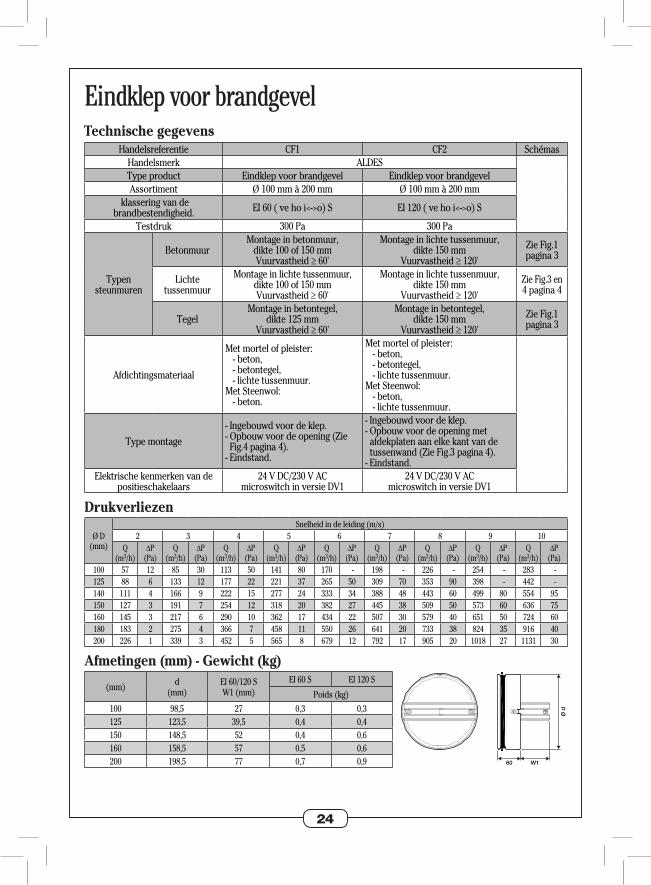
Handelsreferentie CF1 CF2 SchémasHandelsmerk ALDESType product Eindklep voor brandgevel Eindklep voor brandgevelAssortiment Ø 100 mm à 200 mm Ø 100 mm à 200 mm
klassering van de brandbestendigheid. EI 60 ( ve ho i<->o) S EI 120 ( ve ho i<->o) S
Testdruk 300 Pa 300 Pa
Typen steunmuren
BetonmuurMontage in betonmuur,
dikte 100 of 150 mm Vuurvastheid ≥ 60'
Montage in lichte tussenmuur, dikte 150 mm
Vuurvastheid ≥ 120'
Zie Fig.1 pagina 3
Lichte tussenmuur
Montage in lichte tussenmuur, dikte 100 of 150 mm Vuurvastheid ≥ 60'
Montage in lichte tussenmuur, dikte 150 mm
Vuurvastheid ≥ 120'
Zie Fig.3 en 4 pagina 4
TegelMontage in betontegel,
dikte 125 mm Vuurvastheid ≥ 60'
Montage in betontegel, dikte 150 mm
Vuurvastheid ≥ 120'
Zie Fig.1 pagina 3
Afdichtingsmateriaal
Met mortel of pleister:- beton,- betontegel,- lichte tussenmuur.
Met Steenwol:- beton.
Met mortel of pleister:- beton,- betontegel,- lichte tussenmuur.
Met Steenwol:- beton,- lichte tussenmuur.
Type montage
- Ingebouwd voor de klep.- Opbouw voor de opening (Zie Fig.4 pagina 4).
- Eindstand.
- Ingebouwd voor de klep.- Opbouw voor de opening met afdekplaten aan elke kant van de tussenwand (Zie Fig.3 pagina 4).
- Eindstand.Elektrische kenmerken van de
positieschakelaars24 V DC/230 V AC
microswitch in versie DV124 V DC/230 V AC
microswitch in versie DV1
Ø D (mm)
Snelheid in de leiding (m/s)2 3 4 5 6 7 8 9 10
Q (m3/h)
∆P(Pa)
Q(m3/h)
∆P(Pa)
Q(m3/h)
∆P(Pa)
Q(m3/h)
∆P(Pa)
Q(m3/h)
∆P(Pa)
Q(m3/h)
∆P(Pa)
Q(m3/h)
∆P(Pa)
Q(m3/h)
∆P(Pa)
Q(m3/h)
∆P(Pa)
100 57 12 85 30 113 50 141 80 170 - 198 - 226 - 254 - 283 - 125 88 6 133 12 177 22 221 37 265 50 309 70 353 90 398 - 442 - 140 111 4 166 9 222 15 277 24 333 34 388 48 443 60 499 80 554 95150 127 3 191 7 254 12 318 20 382 27 445 38 509 50 573 60 636 75160 145 3 217 6 290 10 362 17 434 22 507 30 579 40 651 50 724 60180 183 2 275 4 366 7 458 11 550 26 641 20 733 38 824 35 916 40200 226 1 339 3 452 5 565 8 679 12 792 17 905 20 1018 27 1131 30
(mm) d (mm)
EI 60/120 S W1 (mm)
EI 60 S EI 120 S
Poids (kg)
100 98,5 27 0,3 0,3125 123,5 39,5 0,4 0,4150 148,5 52 0,4 0,6160 158,5 57 0,5 0,6200 198,5 77 0,7 0,9
Ø d
60 W1
25
IntroduzioneManuale di installazione, funzionamento e manutenzione per serrande tagliafuoco terminale CF1 - CF2, EI60S, EI120S, contenente le informazioni di base e le raccomandazioni riguardanti la progettazione, l‘installazione e l’utilizzo, che devono essere rispettate al fine di garantire un funzionamento corretto e senza problemi dell’unità. E’ necessario leggere attentamente questo manuale e utilizzare la serranda secondo le istruzioni fornite per ottemperare ai requisiti di sicurezza.
ArgomentiImmagini .............................................................................................................................................................................................................................................................................................................. 6Introduzione ............................................................................................................................................................................................................................................................................................... 25Informazioni ................................................................................................................................................................................................................................................................................................ 25Attenzione ..................................................................................................................................................................................................................................................................................................... 25Operazione ................................................................................................................................................................................................................................................................................................... 251 Manuale di installazione ...................................................................................................................................................................................................................................................... 262 Manuale di funzionamento ............................................................................................................................................................................................................................................... 263 Manuale di manutenzione e ispezione ............................................................................................................................................................................................................. 26Informazioni tecniche ....................................................................................................................................................................................................................................................................27Identificazione e certificazione ...........................................................................................................................................................................................................................................33
AttenzioneAlcune parti della serranda tagliafuoco possono avere bordi taglienti, è pertanto necessario utilizzare dei guanti durante l’installazione e l’utilizzo della serranda. Per evitare scariche elettriche, incendi o altri danni che potrebbero verificarsi a seguito di un uso e di un funzionamento scorretto dell’unità, è importante rispettare i seguenti principi:
• E ‘necessario installare il sistema in base al manuale di installazione.• E necessario eseguire il controllo della serranda tagliafuoco secondo il manuale.
FunzionamentoInformazioni generali
Le serrande tagliafuoco terminale sono definite come chiusure tagliafuoco per condotti di ventilazione, da installare nel punto in cui il condotto di ventilazione passa attraverso la parete di compartimentazione al fuoco, oppure al termine del condotto prima della valvola di ventilazione. In caso di incendio le serrande funzionano come elemento di sicurezza antincendio per evitare la propagazione del fuoco nel condotto di ventilazione durante un determinato intervallo di tempo.
• Tutte le unità sono azionate da molle.• Accessori supplementari, ad esempio giunti flessibili, valvole, ecc. Devono essere ordinati separatamente.• Gli accessori sono forniti separatamente e smontati, pronti per essere montati sul posto dal personale responsabile.
Le serrande devono funzionare in un luogo di lavoro protetto da agenti atmosferici e devono essere utilizzate nei condotti di ventilazione per distribuire aria pulita, senza la presenza di alcun altro agente di contaminazione meccanica o chimica nelle seguenti condizioni operative:
• Massive velocità del flusso d’aria di 12 m/s.• Umidita relativa massima dell’aria del 90%.• Temperatura compresa tra -10 e +65° C.
In termini di rumore, le serrande tagliafuoco sono passive. Un aumento della rumorosità si verifica solo quando la serranda si apre o chiude a seguito di ispezione o di incendio, per un tempo inferiore a 5 secondi.
Come standard, tutte le serrande a cartuccia sono dotate di un fusibile termico, che, dopo aver raggiunto o superato la temperatura di 72° C con una tolleranza di ± 1,5° C, sblocca le molle di azionamento, determinando la chiusura delle alette della serranda.
Serranda tagliafuoco terminale
Ital
iano

26
1 Manuale di installazione• Le serrande tagliafuoco terminale sono installate nel condotto, o all’interno della parete compartimentata, oppure al
termine del condotto prima di una valvola di aspirazione/mandata dell’aria.• La distanza tra condotti e tra serrande tagliafuoco deve essere di almeno 200 mm, secondo la normativa EN 1366-2.• Secondo la EN 1366-2, ci devono essere almeno 75 mm tra la parete e la canalizzazione con la serranda tagliafuoco.• La serranda è incorporata nel condotto della costruzione compartimentata al fuoco in modo tale che quando le alette della
ser-randa sono in posizione CHIUSA, il tutto sarà interamente situato all’interno della parete.• La serranda puo essere incorporata in una parete o in un soffitto con uno spessore minimo secondo la EN 1366-2 secondo
la rispettiva classe di resistenza al fuoco.• Tutte le serrande devono essere installate con un asse orizzontale o verticale delle alette.
1.1 Installazione delle CF1 – CF2 in una parete / soffitto utilizzando gesso, malta o calcestruzzo installazione umida (Vedi fig. 1)1. Per l‘installazione, fare una apertura circolare con un diametro minimo di Od + 60 mm nella parete.2. Inserire il condotto all‘interno nel centro dell’apertura.3. Riempire lo spazio tra la parete e il condotto con gesso, malta o calcestruzzo, prestando particolare attenzione a
non contaminare l’interno del condotto.4. Inserire la serranda tagliafuoco nel condotto e assicurarsi che le alette della serranda chiusa si trovino totalmente
all’interno della parete.5. Verificare la funzionalità della serranda (vedi il manuale di istruzioni).
1.2 Installazione alla fine di un canale prima di una valvola (vedi fig.2)CF1 – CF2 puo essere installato in una parete / soffitto al termine di un condotto con una valvola (la valvola deve essere ordinata separatamente). L’installazione è la stessa come descritto nella sezione 1.1, ricordando che l’estremità del condotto deve rimanere in allineamento con il lato della parete / soffitto in cui la valvola sarà installata. Quando si applica la CF1 – CF2, la posizione in cui le sue alette si troveranno dopo la chiusura deve essere ad una distanza di 50 ± 10 mm dalla fine del condotto. Le alette della CF1 – CF2 devono aprirsi in direzione del condotto.
1.3 Installazione delle CF1 - CF2 in una parete in cartongesso con lana mine-rale - Installazione a secco (vedi Fig.3 e 4).1. Per l‘installazione, fare una apertura circolare con un diametro minimo di Od + 60 mm nella parete.2. Inserire il condotto all‘interno nel centro dell’apertura.3. Montare le piastre di copertura alla parete da un lato del condotto.4. Riempire lo spazio tra la parete e il condotto con lana minerale, prestando particolare attenzione a non contaminare
l’interno del condotto.5. Montare le piastre di copertura attorno alla parete sull’altro lato del condotto.6. Inserire la serranda tagliafuoco nel condotto e assicurarsi che le alette a serranda chiusa si trovino all’interno della
parete.7. Verificare la funzionalità della serranda (vedi il manuale di istruzioni).
Le piastre SONO OBBLIGATORIE quando si esegue un’installazione a SECCO!
1.4 Regolazione della serranda in posizione di funzionamento (vedi fig.5)1. Premere entrambe le molle di arresto.2. Aprire le alette in una posizione parallela.3. Inserire il fusibile.
Serranda tagliafuoco terminale
27
2 Funzionamento manualeLa Serranda tagliafuoco terminale è pronta per l’uso quando le sue alette sono aperte secondo il capitolo 1.3 Regolazione della serranda in posizione di funzionamento. La posizione delle alette,se si utilizza una versione DV1, è indicata da un interruttore di fine corsa , che indica la posizione aperta o chiusa delle alette della serranda. Il microinterruttore contiene tre cavi isolati (vedi fig.5) che devono essere portati fuori dal condotto attraverso un foro praticato nel tubo, il piu vicino possibile al microinterruttore e vicino alla parete, il foro sarà chiuso con un anello di gomma.
3 Manutenzione e ispezione manualeIl meccanismo di azionamento mantiene le serrande in stand-by per tutta la vita operativa. Senza il permesso del produttore, non ci devono essere cambiamenti o modifiche effettuate sulla struttura delle serrande. L’operatore dovrà eseguire controlli regolari delle serrande in base alle leggi e regolamenti locali. Salvo diversa indicazione, l’operatore dovrà controllare la serranda ogni 12 mesi.CF1 – CF2 è verificata visivamente dopo aver rimosso il disco della valvola dall’estremità del condotto. Se la serranda viene installata in un condotto che attraversa una parete ignifuga, per accedere alla serranda è necessario staccare il tubo vicino alla parete, sul lato dove le alette della serranda sono aperte.E necessario controllare l‘involucro interno della serranda, il fusibile termico, la sigillatura, il prodotto schiumoso, la condizione della serranda e la sua chiusura, mentre è protetta da un dispositivo antiritorno in posizione chiusa. Non ci devono essere altri oggetti o sporcizia dal condotto di ventilazione all’interno della serranda. Mentre si esegue il controllo bisogna anche concentrarsi sulla integrità del fusibile termico e sulla corretta posizione delle alette nella posizione „aperta“, le alette dovrebbero essere approssimativamente parallele all’asse longitudinale del condotto.Eseguito il controllo della funzionalità della serranda, togliendo il fusibile termico e rilasciando le alette, le stesse si devono chiudere spontaneamente richiamate da una molla. La serranda deve essere completamente chiusa e le alette devono rientrare dietro le molle di arresto.Se si utilizza il DV1, la posizione delle alette è indicata da una connessione del rispettivo circuito di Fig.3. Dopo aver verificato che la tenuta sia integra e sia attestata contro l’intero perimetro del corpo della serranda, si riaprono le alette e nuovamente si fermano nella posizione APERTO utilizzando il collegamento del fusibile termico. Per l‘apertura delle pale è prima necessario spingere la molla di fermo del fusibile termico. Prima di aprire la seconda aletta è possibile fissare la prima in posizione APERTO inserendo un oggetto appropriato tra l’aletta ed il corpo della serranda (questo oggetto deve essere rimosso quando il fusibile termico viene riarmato.In caso di accesso difficoltoso quando si controlla la funzionalità della serranda per la chiusura completa delle alette (serranda molto piccola, tubo nella parete troppo lungo…) è possibile staccare la serranda dal condotto. Possiamo farlo sia estraendola dal condotto tenendola per le sue alette aperte, oppure separando il tubo sul lato del muro e spingendo la serranda fuori dal condotto. Se si utilizza un interruttore di fine corsa è necessario scollegare i cavi dell’interruttore dal terminale esterno del condotto e tirare i fili nel condotto prima di staccare la serranda. Dopo questa operazione, è possibile estrarre la serranda dal condotto. Nel rimontaggio della serranda nel condotto è anche essenziale controllare la flessibilita della guarnizione perimetrale e in caso di deformazione permanente, sostituirla per garantire un collegamento corretto tra serranda e condotto.
Interventi di controllo consigliati secondo la norma EN 15650
1. data dell’ispezione.2. controllo del collegamento del fine corsa.3. verifica della pulizia della serranda, pulire se necessario.4. verifica delle elette e della tenuta, correggere.5. verifica della chiusura della serranda tagliafuoco, per I dettagli vedere la sezione precedente.6. verificare se la serranda si muove pur essendo nella sua posizione di aperto e chiuso, rettificare.7. controllo dell’interruttore di fine corsa che indica la posizione aperta e chiusa, correggere.8. verificare se la serranda viene spostata dalla sua posizione standard. La posizione di CF1 – CF2 è corretta quando,
dopo la chiusura, le alette sono all’interno delle due facce della parete.
3.2.1 Sostituzione del fusibile termicoQuando si sostituisce il fusibile termico è necessario seguire le istruzioni da 1.3 Regolazione della serranda nel manuale operativo di posizione, togliere il fusibile termico e metterne uno nuovo.
Serranda tagliafuoco terminale
Ital
iano

28
Informazioni tecniche
Perdite di carica
Ingombro (mm) - Peso (kg)
Referenza commerciale CF1 CF2 SchémasMarca commerciale ALDES
Tipo di prodotto Serranda tagliafuoco terminale Serranda tagliafuoco terminaleGamma Ø100mm - 200mm Ø100mm - 200mm
Classificazione di resistenza al fuoco EI 60( ve ho i<->o) S EI 120( ve ho i<->o) S
Pressione di test 300 Pa 300 Pa
Tipi di pareti supporto
Muro in calcestruzzo
Montaggio in muro calcestruzzo, spessore 100 o 150 mm Resistenza al fuoco ≥ 60'
Montaggio in parete divisoria leggera, spessore 150 mm
Resistenza al fuoco ≥ 120'
Vedi Fig.1 pag. 3
Parete leggeraMontaggio in parete divisoria
leggera, spessore 100 o 150 mm Resistenza al fuoco ≥ 60'
Montaggio in parete divisoria leggera, spessore 150 mm
Resistenza al fuoco≥ 120'
Vedi Fig.3 e 4 pag. 4
DallaMontaggio in dalla calcestruzzo,
spessore 125 mm Resistenza al fuoco ≥ 60'
Montaggio in dalla calcestruzzo, spessore 150 mm
Resistenza al fuoco ≥ 120'
Vedi Fig.1 pag. 3
Otturamento
Con malta o gesso:- calcestruzzo,- dalla calcestruzzo,- parete divisoria leggera.
Con lana di roccia:- calcestruzzo.
Con malta o gesso:- calcestruzzo,- dalla calcestruzzo,- parete divisoria leggera.
Con lana di roccia:- calcestruzzo,- parete divisoria leggera.
Tipo di montaggio
- Ad incastro per la serranda.- Ad applique per la bocca (Vedi Fig.4 pagina 4).
- Posizione terminale.
- Ad incastro per la serranda.- Ad applique per la bocca con piastre di copertura su ciascun lato della parete (Vedi Fig.3 pagina 4).
- Posizione terminaleCaratteristiche elettriche dei
contatti di posizioni24 V DC/230V AC
microswitch nella versione DV124 V DC/230V AC
microswitch nella versione DV1
Ø D (mm)
Velocità senza condotto (m/s)2 3 4 5 6 7 8 9 10
Q (m3/h)
∆P(Pa)
Q(m3/h)
∆P(Pa)
Q(m3/h)
∆P(Pa)
Q(m3/h)
∆P(Pa)
Q(m3/h)
∆P(Pa)
Q(m3/h)
∆P(Pa)
Q(m3/h)
∆P(Pa)
Q(m3/h)
∆P(Pa)
Q(m3/h)
∆P(Pa)
100 57 12 85 30 113 50 141 80 170 - 198 - 226 - 254 - 283 - 125 88 6 133 12 177 22 221 37 265 50 309 70 353 90 398 - 442 - 140 111 4 166 9 222 15 277 24 333 34 388 48 443 60 499 80 554 95150 127 3 191 7 254 12 318 20 382 27 445 38 509 50 573 60 636 75160 145 3 217 6 290 10 362 17 434 22 507 30 579 40 651 50 724 60180 183 2 275 4 366 7 458 11 550 26 641 20 733 38 824 35 916 40200 226 1 339 3 452 5 565 8 679 12 792 17 905 20 1018 27 1131 30
(mm) d (mm)
EI 60/120 S W1 (mm)
EI 60 S EI 120 S
Poids (kg)
100 98,5 27 0,3 0,3125 123,5 39,5 0,4 0,4150 148,5 52 0,4 0,6160 158,5 57 0,5 0,6200 198,5 77 0,7 0,9
Serranda tagliafuoco terminale
Ø d
60 W1
29
IntroducciónEste manual de instalación, utilización y control se aplica a todos los válvula terminal cortafuego tipo CF1 – CF2, EI60S, EI120S. Con el fin de garantizar un funcionamiento correcto y fiable de la unidad respete las indicaciones y recomendaciones indicadas en este manual. Para asegurar el buen funcionamiento de la unidad, se ruega leer detenidamente las instrucciones indicadas en este manual y utilizar el Válvula terminal cortafuego conforme a dichas instrucciones respetando las instrucciones de seguridad.
ÍndiceFiguras ............................................................................................................................................................................................................................................................................................................... 6Introducción ........................................................................................................................................................................................................................................................................................... 29Índice ................................................................................................................................................................................................................................................................................................................ 29Advertencias .......................................................................................................................................................................................................................................................................................... 29Utilización .................................................................................................................................................................................................................................................................................................. 291 Instrucciones de instalación ........................................................................................................................................................................................................................................ 302 Instrucciones de utilización ......................................................................................................................................................................................................................................... 303 Instrucciones de mantenimiento y control ............................................................................................................................................................................................. 30Informaciones técnicas ...........................................................................................................................................................................................................................................................31Identificación y certificación..............................................................................................................................................................................................................................................33
AdvertenciasCiertas partes punzantes del Válvula terminal cortafuego pueden causar heridas. Para evitar dicho riesgo, utilizar guantes durante la manipulación del Válvula terminal cortafuego. Para evitar el riesgo de electrocución, incendio u otros peligros susceptibles de producirse por una utilización incorrecta de la unidad, se deben respetar las siguientes instrucciones:
• Instalar el sistema conforme al manual de instalación.• Realizar los controles del Válvula terminal cortafuego, conforme al manual.
UtilizaciónInformación general
Los válvula terminal cortafuego son dispositivos de obturación instalados en los conductos de ventilación, más concretamente en los pasos de tabiques o forjados o en los extremos de los conductos situados en los tabiques, delante de la boca. En caso de incendio, los válvula terminal cortafuego constituyen un elemento de seguridad resistente al fuego. Los válvula terminal cortafuego impiden la propagación del fuego por los conductos durante un periodo de tiempo definido.
• Cada cartucho se cierra por la fuerza de unos muelles de disparo.• Los accesorios como por ejemplo los manguitos flexibles, las bocas de ventilación, etc. pueden ser pedidos por separado.• Los accesorios se suministran por separado y desmontados. El montaje y la instalación se realizan por técnicos en la obra.Los válvula terminal cortafuego están destinados a una aplicación en sitios protegidos del viento. Solo se pueden instalar en los conductos de ventilación de distribución de aire sin añadidos de tipo mecánico o químico respetando las siguientes condiciones de utilización:• Velocidad máxima de circulación del aire – 12 m/s.• Humedad relativa del aire - 90%.• Rango de temperatura de -10 a +65° C
Los válvula terminal cortafuego no producen un ruido importante. Un funcionamiento ruidoso se produce durante un período de tiempo no superior a 5 segundos, durante la apertura o el cierre debido a un disparo del test de fuego o por un incendio.
De forma estándar, cada Válvula terminal cortafuego viene equipado de un fusible térmico susceptible de dispararse a una temperatura igual o superior a 72° C (con una desviación de ± 1,5° C). El fusible desbloquea los muelles de disparo que cierran las lamas del Válvula terminal cortafuego.
Válvula terminal cortafuego
Espa
ñol
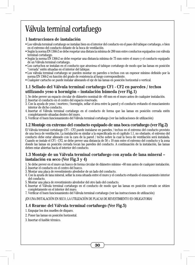
30
1 Instrucciones de instalación• Los válvula terminal cortafuego se instalan bien en el interior del conducto en el paso del tabique cortafuego, o bien
en el extremo del conducto delante de la boca de ventilación.• Según la norma EN 1366-2 se debe respetar una distancia mínima de 200 mm entre conductos equipados con válvula
terminal cortafuego.• Según la norma EN 1366-2 se debe respetar una distancia mínima de 75 mm entre el muro y el conducto equipado
de un Válvula terminal cortafuego.• Los cartuchos se instalan en el conducto que atraviesa el tabique cortafuego de modo que las lamas en posición
“cerrada” estén situadas en el interior del tabique.• Los válvula terminal cortafuego se pueden montar en paredes o techos con un espesor mínimo definido por la
norma EN 1366-2 en función del grado de resistencia al fuego correspondiente.• Cualquier cartucho se puede instalar alineando el eje de las lamas en posición horizontal o vertical.
1.1 Sellado del Válvula terminal cortafuego CF1 - CF2 en paredes / techos utilizando yeso u hormigón – instalación húmeda (ver Fig.1)1. Se debe prever un espacio circular de diámetro nominal de +60 mm en el muro antes de cualquier instalación.2. Insertar el conducto en el centro del espacio reservado.3. Con la ayuda de yeso / mortero / hormigón, sellar el área entre la pared y el conducto evitando el ensuciamiento
interior de dicho conducto.4. Insertar el Válvula terminal cortafuego en el conducto de forma que las lamas en posición cerrada estén
completamente situadas dentro del muro.5. Verificar el buen funcionamiento del Válvula terminal cortafuego (ver las indicaciones de utilización)
1.2 Montaje en extremo del conducto equipado de una boca cortafuego (ver Fig.2)El Válvula terminal cortafuego CF1 - CF2 puede instalarse en paredes / techos en el extremo del conducto provisto de una boca de ventilación. La instalación es similar a la especificada en el capítulo 1.1, no obstante, el extremo del conducto debe estar alineado con la cara de la pared / techo sobre la cual la boca de ventilación será instalada. Cuando se instale el CF1 - CF2, se debe prever una distancia de 50 ± 10 mm entre el extremo del conducto y la zona donde las lamas en posición cerrada tocan las paredes del conducto. A continuación de la instalación, las lamas deben estar abiertas hacia el interior del conducto.
1.3 Montaje de un Válvula terminal cortafuego con ayuda de lana mineral – instalación en seco (Ver Fig.3 y 4)1. Se debe prever en el muro un hueco de forma circular de diámetro mínimo +60 mm antes de cualquier instalación.2. Insertar el conducto en el centro del hueco.3. Montar una placa de revestimiento alrededor de un lado del conducto.4. Con la ayuda de lana mineral, sellar la zona situada entre el muro y el conducto evitando el ensuciamiento interior
del conducto.5. Montar una placa de revestimiento alrededor del otro lado del conducto.6. Insertar el Válvula terminal cortafuego en el conducto de modo que las lamas en posición cerrado se sitúen
completamente en el interior del muro.7. Verificar el buen funcionamiento del Válvula terminal cortafuego (ver las instrucciones de utilización)
¡EN UNA INSTALACIÓN EN SECO, LA UTILIZACIÓN DE PLACAS DE REVESTIMIENTO ES OBLIGATORIA!
1.4 Rearme del Válvula terminal cortafuego (Ver Fig.5)1. Empujar los dos muelles de disparo.2. Poner las lamas en posición horizontal.3. Insertar el fusible térmico.
Válvula terminal cortafuego
31
2 Instrucciones de utilizaciónEl rearme del Válvula terminal cortafuego se realiza abriendo las lamas conforme a las instrucciones especificadas en el capítulo 1.4. (Rearme del Válvula terminal cortafuego). Si se utiliza el tipo DV1, la posición de abertura o cierre de las lamas se señala por un interruptor final de carrera. El microinterruptor viene provisto de 3 cables aislados que - con el objeto de ser sacados fuera del conducto – deben pasar por una abertura en el conducto lo más próxima posible al microinterruptor y a la pared. Esta abertura debe ir provista de un pasacable de caucho.
3 Instrucciones de mantenimiento y controlEl dispositivo de disparo mantiene las lamas en posición de espera durante toda la vida operacional. No se puede realizar ninguna intervención sobre los válvula terminal cortafuego sin la previa autorización del fabricante. El propietario es el responsable de hacer realizar los controles periódicos de los válvula terminal cortafuego conforme a la reglamentación y a las normas locales en vigor. Salvo indicación contraria, se debe hacer un control cada 12 meses.El control de los CF1 - CF2 se efectúa visualmente, después del desmontaje de la boca de ventilación del extremo del conducto. Si el cartucho de ventilación está instalado en el conducto que atraviesa el muro cortafuego, es necesario separar el conducto en las proximidades de la pared hacia el lado que se abren las lamas con el fin de facilitar el acceso al cartucho.Durante el control se debe examinar igualmente el cuerpo interno del Válvula terminal cortafuego, el fusible térmico, la estanqueidad, la espuma, el estado de las lamas y la precisión del cierre de las lamas en contacto con el tope. El cuerpo interno del Válvula terminal cortafuego no puede contener ningún objeto ni polvo aportado por los conductos de ventilación. La integridad del fusible térmico debe también ser objeto de control al igual que una posición correcta de las lamas después del rearme (posición de abertura). La posición de las lamas debe ser casi paralela con el eje longitudinal del conducto. Con el fin de verificar el correcto funcionamiento del Válvula terminal cortafuego, hay que desmontar el fusible térmico y soltar las lamas para que se cierren espontáneamente gracias a la energía de los muelles de retorno. Cierre completamente el Válvula terminal cortafuego de tal forma que las lamas se detengan antes de los muelles. Si se utiliza el tipo DV1, la posición de la lama está indicada por la conexión del circuito correspondiente según Fig.3 .Antes de rearmar las lamas y volver a montar el fusible, es necesario examinar el estado de la estanqueidad y de su acoplamiento homogéneo al perímetro del conducto. Para abrir las lamas, primero empuje el muelle. A continuación, utilice un gancho atado a la apertura del portafusible para abrir una lama. Antes de abrir la otra lama, puede bloquear la primera en su posición de espera mediante la inserción de un objeto adecuado entre la lama y el cuerpo (no olvide quitar el objeto después del montaje del fusible). Con el fin de realizar un ensayo de control en un Válvula terminal cortafuego difícilmente accesible (a causa de pequeñas dimensiones, de la longitud del conducto, etc.) efectuado por el cierre completo de sus lamas, es posible sacar el Válvula terminal cortafuego fuera del conducto. En ese caso, retirar el Válvula terminal cortafuego sujetando las lamas en la posición de abertura. Si procediera, separar el conducto del otro lado del muro cortafuego y empujar el cartucho hacia el exterior. En el caso de utilización de un interruptor final de carrera que señalice el cierre de las lamas, antes de sacar el Válvula terminal cortafuego comenzar por soltar los hilos de la regleta y tirarlos hacia el interior del conducto. Antes de volver a montar el Válvula terminal cortafuego después de un control, es necesario examinar la flexibilidad de la estanqueidad alrededor del perímetro. Si se constata una deformación permanente, se debe reemplazar la junta de estanqueidad con el fin de asegurar una fijación correcta del cartucho en el conducto.
Procedimiento de control recomendado por la norma EN 15650:
1. Marque la fecha de inspección.2. Inspeccione la conexión del interruptor final de carrera, teniendo especialmente en cuenta las zonas que tienen
riesgo de sufrir un deterioro.3. Examine la limpieza del cartucho y límpielo, si es necesario.4. Examinar el estado de las lamas y la estanqueidad, corregir si necesario.5. Verifique la posición correcta de las lamas en posición de cierre (ver párrafo anterior para información detallada)6. Verifique el movimiento del Válvula terminal cortafuego en posición de abertura y cierre, corregir si necesario.7. Verifique el buen funcionamiento del interruptor final de carrera es posición de abertura y de cierre, corregir si necesario.8. Verifique si el Válvula terminal cortafuego se encuentra en una posición estable. El Válvula terminal cortafuego CF1
– CF2 está en una posición correcta si las lamas, después de su cierre, permanecen entre los planos formado por los lados externos de las paredes – una posición ideal se encuentra en el medio de estos dos planos.
3.2.1 Sustitución del fusiblePara sustituir el fusible, se deben seguir las instrucciones mencionados en el capítulo 1.4. Para poner el cartucho en servicio, se debe desmontar el antiguo fusible e insertar el nuevo.
Válvula terminal cortafuego
Espa
ñol
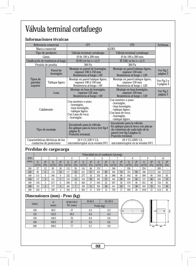
32
Válvula terminal cortafuegoInformaciones técnicas
Pérdidas de cargacarga
Dimensiones (mm) - Peso (kg)
Referencia comercial CF1 CF2 SchémasMarca comercial ALDESTipo de producto Válvula terminal cortafuego Válvula terminal cortafuego
Gama Ø de 100 a 200 mm Ø de 100 a 200 mmClasificación de resistencia al fuego EI 60 (ve ho i<->o) S EI 120( ve ho i<->o) S
Presión de prueba 300 Pa 300 Pa
Tipos de paredes soporte
Pared de hormigón
Montaje en pared de hormigón, espesor 100 ó 150 mm
Resistencia al fuego ≥ 60'
Montaje en pared tabique ligero, espesor 150 mm
Resistencia al fuego ≥ 120'
Ver Fig.1 página 3
Tabique ligeroMontaje en pared tabique ligero,
espesor 100 ó 150 mmResistencia al fuego ≥ 60'
Montaje en pared tabique ligero, espesor 150 mm
Resistencia al fuego ≥ 120'
Ver Fig.3 y 4 página 4
LosaMontaje en losa de hormigón,
espesor 125 mmResistencia al fuego ≥ 60'
Montaje en losa hormigón, espesor 150 mm
Resistencia al fuego ≥ 120'
Ver Fig.1 página 3
Calafateado
Con mortero o yeso:- hormigón,- losa hormigón,- tabique ligero.
Con Lana de roca:- hormigón.
Con mortero o yeso:- hormigón,- losa hormigón,- tabique ligero.
Con lana de roca:- hormigón, - tabique ligero.
Tipo de montaje
- Encastrado para la válvula.- En aplique para la boca (ver fig.4 página 4).
- Posición terminal.
- Encastrado para la válvula.- En aplique para la boca con placas de cobertura de cada lado de la pared (ver fig.3 página 4).
- Posición terminal.Características eléctricas de los
contactos de posiciones24 V CC/230 V CA
microinterruptor en la versión DV124 V CC/230V CA
microinterruptor en la versión DV1
Ø D (mm)
Velocidad en el conducto (m/seg)2 3 4 5 6 7 8 9 10
Q (m3/h)
∆P(Pa)
Q(m3/h)
∆P(Pa)
Q(m3/h)
∆P(Pa)
Q(m3/h)
∆P(Pa)
Q(m3/h)
∆P(Pa)
Q(m3/h)
∆P(Pa)
Q(m3/h)
∆P(Pa)
Q(m3/h)
∆P(Pa)
Q(m3/h)
∆P(Pa)
100 57 12 85 30 113 50 141 80 170 - 198 - 226 - 254 - 283 - 125 88 6 133 12 177 22 221 37 265 50 309 70 353 90 398 - 442 - 140 111 4 166 9 222 15 277 24 333 34 388 48 443 60 499 80 554 95150 127 3 191 7 254 12 318 20 382 27 445 38 509 50 573 60 636 75160 145 3 217 6 290 10 362 17 434 22 507 30 579 40 651 50 724 60180 183 2 275 4 366 7 458 11 550 26 641 20 733 38 824 35 916 40200 226 1 339 3 452 5 565 8 679 12 792 17 905 20 1018 27 1131 30
(mm) d (mm)
EI 60/120 S W1 (mm)
EI 60 S EI 120 S
Poids (kg)
100 98,5 27 0,3 0,3125 123,5 39,5 0,4 0,4150 148,5 52 0,4 0,6160 158,5 57 0,5 0,6200 198,5 77 0,7 0,9
Ø d
60 W1
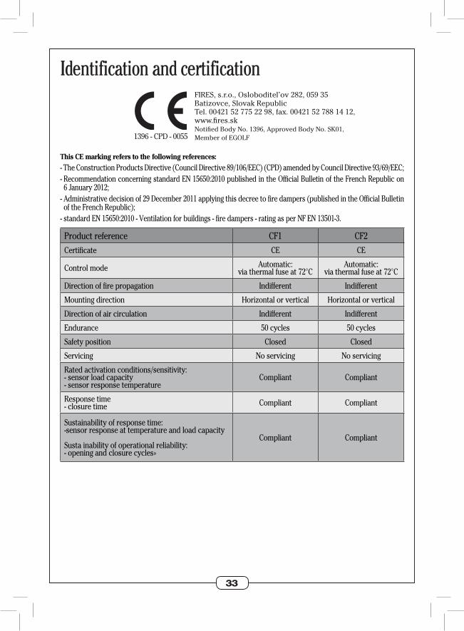
33
Identification and certification
Product reference CF1 CF2Certificate CE CE
Control mode Automatic: via thermal fuse at 72°C
Automatic: via thermal fuse at 72°C
Direction of fire propagation Indifferent Indifferent
Mounting direction Horizontal or vertical Horizontal or vertical
Direction of air circulation Indifferent Indifferent
Endurance 50 cycles 50 cycles
Safety position Closed Closed
Servicing No servicing No servicing
Rated activation conditions/sensitivity:- sensor load capacity - sensor response temperature
Compliant Compliant
Response time- closure time Compliant Compliant
Sustainability of response time:-sensor response at temperature and load capacity Susta inability of operational reliability:- opening and closure cycles»
Compliant Compliant
This CE marking refers to the following references:
- The Construction Products Directive (Council Directive 89/106/EEC) (CPD) amended by Council Directive 93/69/EEC;- Recommendation concerning standard EN 15650:2010 published in the Official Bulletin of the French Republic on 6 January 2012;
- Administrative decision of 29 December 2011 applying this decree to fire dampers (published in the Official Bulletin of the French Republic);
- standard EN 15650:2010 - Ventilation for buildings - fire dampers - rating as per NF EN 13501-3.
FIRES, s.r.o., Osloboditel’ov 282, 059 35 Batizovce, Slovak RepublicTel. 00421 52 775 22 98, fax. 00421 52 788 14 12, www.fires.skNotified Body No. 1396, Approved Body No. SK01, Member of EGOLF1396 - CPD - 0055
34
35

www.aldes.com ALDE
S se
rése
rve l
e dro
it d’a
ppor
ter t
oute
s mod
ifica
tions
liée
s à l’é
volu
tion
de la
tech
niqu
e.