universidad autonoma de nuevo le on · david juvencio rios soria. candidato para el grado de doctor...
TRANSCRIPT

Universidad Autonoma de Nuevo Leon
Facultad de Ingenierıa Mecanica y Electrica
Division de Estudios de Posgrado
Natural hand-gesture interaction
(Interaccion natural con gestos manuales)
por
David Juvencio Rios Soria
en opcion al grado de
Doctor en Ingenierıa
con acentuacion en Computacion y Mecatronica
San Nicolas de los Garza, Nuevo Leon junio 2013

Universidad Autonoma de Nuevo Leon
Facultad de Ingenierıa Mecanica y Electrica
Division de Estudios de Posgrado
Los miembros del Comite de Tesis recomendamos que la Tesis �Natural hand-
gesture interaction�(Interaccion natural con gestos manuales), realizada por el alumno
David Juvencio Rios Soria, con numero de matrıcula 1213374, sea aceptada para su
defensa como opcion al grado de Doctor en Ingenierıa con acentuacion en Com-
putacion y Mecatronica.
El Comite de Tesis
Dra. Satu Elisa Schaeffer
Asesor
Dr. Gerardo Maximiliano Mendez Dr. Luis Martın Torres Trevino
Revisor Revisor
Dra. Griselda Quiroz Compean Dr. Hector Hugo Aviles Arriaga
Revisor Revisor
Vo. Bo.
Dr. Moises Hinojosa Rivera
Division de Estudios de Posgrado
San Nicolas de los Garza, Nuevo Leon, junio 2013

Resumen
David Juvencio Rios Soria.
Candidato para el grado de Doctor en Ingenierıa con acentuacion en Computacion
y Mecatronica
Universidad Autonoma de Nuevo Leon.
Facultad de Ingenierıa Mecanica y Electrica.
Tıtulo del estudio:
Interaccion natural con gestos manuales
Numero de paginas: 108.
Objetivos y metodo de estudio: El objetivo de este trabajo es realizar un es-
tudio acerca de los diferentes metodos de interaccion humano-computadora basados
en gestos manuales y proponer un sistema que sea facil de utilizar y pueda ser usado
en diferentes aplicaciones. Para este trabajo se realizo un estudio de los sistemas ac-
tuales de interaccion humano-computadora, ası como de los fundamentos cognitivos
y de diseno en los cuales debe de estar basado el desarrollo de este tipo de sistemas.
Uno de los propositos de este trabajo es la creacion de un sistema de re-
conocimiento de gestos manuales; para el desarrollo de este sistema se hizo un
estudio acerca de tecnicas de vision computacional. Para comprobar el correcto
funcionamiento del sistema se llevaron a cabo experimentos con usuarios reales.
iv

Resumen v
Contribuciones y conclusiones: Se creo un algoritmo de reconocimiento de
gestos manuales basado en tecnicas de vision computacional; este sistema es capaz de
detectar seis diferentes senas manuales en tiempo real. Estas senas se podrıan usar en
secuencia para crear ası un vocabulario mas amplio usando diferentes combinaciones
de estas.
El sistema se puede implementar facilmente utilizando una camara web y puede
ser adaptado para ser usado en diferentes aplicaciones. Se crearon algunas pruebas
de conceptos que demuestran como se puede utilizar este sistema para controlar dis-
tintos dispositivos electronicos. Se realizaron experimentos con usuarios utilizando
este sistema obteniendo una precision del 93% en el reconocimiento de gestos, re-
quiriendo 270 milisegundos en promedio para el tiempo de ejecucion.
Firma del asesor:
Dra. Satu Elisa Schaeffer

Abstract
David Juvencio Rios Soria.
Candidate for the degree of Doctor of Engineering in Computation and Mechatronics
Universidad Autonoma de Nuevo Leon.
Facultad de Ingenierıa Mecanica y Electrica.
Study title:
Natural hand-gesture interaction
Number of pages: 108.
Objectives and methodology: The objective of this work is to study the dif-
ferent methods of human-computer interaction based on hand-gestures and propose
a system that is easy to use and can be used in different applications. We conducted
a literature review of current work in human-computer interaction as well as the
cognitive and design foundations on which the development of such systems should
be based.
The main purpose of this work is to create a hand-gesture recognition system.
For the development of this system, we applied computer-vision techniques. To
verify the correct operation of the system, experiments were carried out with real
users.
vi

Abstract vii
Contributions and conclusions: A hand-gesture recognition algorithm was
created based on computer-vision techniques; this system is able to recognize six
different hand signals in real time. These signs could be used in a sequence to create
a bigger vocabulary using different combinations of the signs.
The system can be easily implemented using a webcam and can be adapted for
use in different applications. Some conceptual prototypes were created to demon-
strate how this system can be used to control various electronic devices. Experiments
were conducted with real users interacting with the system, obtaining an accuracy
of 93 % in gesture recognition, using 270 milliseconds average for processing time.
Signature of advisor:
Dra. Satu Elisa Schaeffer

Contents
Resumen iv
Abstract vi
Nomenclature xvii
1 Introduction 1
1.1 Mobile Computing . . . . . . . . . . . . . . . . . . . . . . . . . . . . 1
1.2 Distributed Computing . . . . . . . . . . . . . . . . . . . . . . . . . . 2
1.3 Mobile Distributed Computing . . . . . . . . . . . . . . . . . . . . . . 2
1.4 Ubiquitous Computing . . . . . . . . . . . . . . . . . . . . . . . . . . 3
1.4.1 Location-Based Computing . . . . . . . . . . . . . . . . . . . 4
1.4.2 Mobile Assistance . . . . . . . . . . . . . . . . . . . . . . . . . 4
1.4.3 Emergency-Response Systems . . . . . . . . . . . . . . . . . . 5
1.4.4 Mobile Collaboration . . . . . . . . . . . . . . . . . . . . . . . 6
1.4.5 Context-Aware Systems . . . . . . . . . . . . . . . . . . . . . 6
1.5 Methods for Estimating Location . . . . . . . . . . . . . . . . . . . . 7
1.5.1 Global Positioning System . . . . . . . . . . . . . . . . . . . . 8
viii

Contents ix
1.5.2 Radio Frequency Identification . . . . . . . . . . . . . . . . . . 8
1.5.3 Special Mobile Group . . . . . . . . . . . . . . . . . . . . . . . 9
1.5.4 Orientation Sensors . . . . . . . . . . . . . . . . . . . . . . . . 9
1.6 Information Visualization . . . . . . . . . . . . . . . . . . . . . . . . 10
1.7 Augmented Reality . . . . . . . . . . . . . . . . . . . . . . . . . . . . 11
1.8 Virtual Object Interaction . . . . . . . . . . . . . . . . . . . . . . . . 13
1.9 Digital Advertising . . . . . . . . . . . . . . . . . . . . . . . . . . . . 14
1.10 Motivation of the Thesis . . . . . . . . . . . . . . . . . . . . . . . . . 15
1.11 Thesis Structure . . . . . . . . . . . . . . . . . . . . . . . . . . . . . . 17
1.12 Publication . . . . . . . . . . . . . . . . . . . . . . . . . . . . . . . . 17
2 Background 18
2.1 Perception . . . . . . . . . . . . . . . . . . . . . . . . . . . . . . . . . 18
2.2 Memory . . . . . . . . . . . . . . . . . . . . . . . . . . . . . . . . . . 33
2.3 Learning . . . . . . . . . . . . . . . . . . . . . . . . . . . . . . . . . . 35
2.4 Cognitive Psychology . . . . . . . . . . . . . . . . . . . . . . . . . . . 37
2.5 Designing Interfaces . . . . . . . . . . . . . . . . . . . . . . . . . . . . 42
2.6 Human-Computer Interaction . . . . . . . . . . . . . . . . . . . . . . 48
2.6.1 Vision-Based Interfaces . . . . . . . . . . . . . . . . . . . . . . 48
2.6.2 Hand-Gesture Interaction . . . . . . . . . . . . . . . . . . . . 51
2.6.3 Vision-Based Pose Estimation . . . . . . . . . . . . . . . . . . 51
2.6.4 Gesture-Based Interaction Systems . . . . . . . . . . . . . . . 52

Contents x
2.6.5 Research Challenges . . . . . . . . . . . . . . . . . . . . . . . 58
2.7 Computer Vision . . . . . . . . . . . . . . . . . . . . . . . . . . . . . 59
2.7.1 Image Processing . . . . . . . . . . . . . . . . . . . . . . . . . 59
2.7.2 Video Processing . . . . . . . . . . . . . . . . . . . . . . . . . 60
2.7.3 Filtering . . . . . . . . . . . . . . . . . . . . . . . . . . . . . . 61
2.7.4 Pattern Recognition . . . . . . . . . . . . . . . . . . . . . . . 61
2.8 Related Work . . . . . . . . . . . . . . . . . . . . . . . . . . . . . . . 62
2.8.1 Device Interaction . . . . . . . . . . . . . . . . . . . . . . . . 62
2.8.2 Virtual Object Interaction . . . . . . . . . . . . . . . . . . . . 65
2.8.3 Hand-Sign Language Recognition . . . . . . . . . . . . . . . . 66
2.8.4 Robot Control . . . . . . . . . . . . . . . . . . . . . . . . . . . 67
3 Hand Recognition 69
3.1 Skin-Color Filtering . . . . . . . . . . . . . . . . . . . . . . . . . . . . 70
3.1.1 Skin-Color Filter RGB . . . . . . . . . . . . . . . . . . . . . . 71
3.1.2 Skin-Color Filter YCbCr . . . . . . . . . . . . . . . . . . . . . 72
3.2 Edge Detection . . . . . . . . . . . . . . . . . . . . . . . . . . . . . . 72
3.3 Convex Hull . . . . . . . . . . . . . . . . . . . . . . . . . . . . . . . . 74
3.4 Convexity Defects . . . . . . . . . . . . . . . . . . . . . . . . . . . . . 75
4 Prototype 77
4.1 Hardware . . . . . . . . . . . . . . . . . . . . . . . . . . . . . . . . . 77
4.2 Software . . . . . . . . . . . . . . . . . . . . . . . . . . . . . . . . . . 78
Contents xi
5 Experiments 80
5.1 User Experiments . . . . . . . . . . . . . . . . . . . . . . . . . . . . . 80
5.1.1 Setup . . . . . . . . . . . . . . . . . . . . . . . . . . . . . . . 80
5.1.2 First Set of Experiments . . . . . . . . . . . . . . . . . . . . . 82
5.1.3 Second Set of Experiments . . . . . . . . . . . . . . . . . . . . 84
5.2 Computational Experiments . . . . . . . . . . . . . . . . . . . . . . . 85
5.2.1 Noise . . . . . . . . . . . . . . . . . . . . . . . . . . . . . . . . 86
5.2.2 Area . . . . . . . . . . . . . . . . . . . . . . . . . . . . . . . . 87
5.2.3 Processing Time . . . . . . . . . . . . . . . . . . . . . . . . . 87
6 Proofs of Concept 91
6.1 LEGO Robot . . . . . . . . . . . . . . . . . . . . . . . . . . . . . . . 92
6.2 GPS Device . . . . . . . . . . . . . . . . . . . . . . . . . . . . . . . . 92
6.3 AR.Drone . . . . . . . . . . . . . . . . . . . . . . . . . . . . . . . . . 94
7 Conclusions and Future Work 95

List of Figures
1.1 The LUMUS personal display . . . . . . . . . . . . . . . . . . . . . . 10
1.2 The Layar augmented reality application . . . . . . . . . . . . . . . . 12
1.3 Handvu virtual object interaction . . . . . . . . . . . . . . . . . . . . 13
1.4 Digital advertising on a bus that changes depending on the location
and the time of day. (Taken from [34].) . . . . . . . . . . . . . . . . . 14
2.1 Law of proximity example . . . . . . . . . . . . . . . . . . . . . . . . 21
2.2 Examples of enclosure . . . . . . . . . . . . . . . . . . . . . . . . . . 22
2.3 Example of figure–ground . . . . . . . . . . . . . . . . . . . . . . . . 23
2.4 Color wheel. . . . . . . . . . . . . . . . . . . . . . . . . . . . . . . . . 24
2.5 Motion perception. . . . . . . . . . . . . . . . . . . . . . . . . . . . . 27
2.6 Example of perception biased by experience: when the sensing system
was prepared to see forms of construction, one see forms of construc-
tion and the white areas are barely recorded . . . . . . . . . . . . . . 29
2.7 Example of perception biased by experience: if the positions of the
buttons “Next” and “Return” change, many people do not immedi-
ately notice the change. (Taken from [61].) . . . . . . . . . . . . . . . 30
xii
List of Figures xiii
2.8 Example of proximity: the elements on a screen can be visually
grouped using borders or putting them closer . . . . . . . . . . . . . . 30
2.9 Example of figure vs. ground (screen capture of Google Chrome). . . 31
2.10 Uppercase text is hard to read. . . . . . . . . . . . . . . . . . . . . . 32
2.11 Example of visual noise. (Taken from [61].) . . . . . . . . . . . . . . . 32
2.12 The reservation system of an airline shows the progress of the user to
know at what stage the process is . . . . . . . . . . . . . . . . . . . . 34
2.13 Using icons to recognize items on a menu . . . . . . . . . . . . . . . . 35
2.14 Mental models. (Taken from [11].) . . . . . . . . . . . . . . . . . . . . 39
2.15 Using images to recognize items on a menu . . . . . . . . . . . . . . . 39
2.16 Experience levels. (Taken from [30].) . . . . . . . . . . . . . . . . . . 40
2.17 In-air typing interface of Fastfinger [60]. . . . . . . . . . . . . . . . . 52
2.18 UbiHand wrist-worn input device [2]. . . . . . . . . . . . . . . . . . . 53
2.19 The Handvu system gestures. . . . . . . . . . . . . . . . . . . . . . . 53
2.20 Orange interactive windoe . . . . . . . . . . . . . . . . . . . . . . . . 54
2.21 The Sixthsense system uses a camera and a projector to convert any
surface in an interactive surface [42]. . . . . . . . . . . . . . . . . . . 54
2.22 Hand signs used in the Sixthsense system [42]. . . . . . . . . . . . . 55
2.23 Opportunity area. . . . . . . . . . . . . . . . . . . . . . . . . . . . . . 59
2.24 TV gesture interaction. (Taken from [37].) . . . . . . . . . . . . . . . 62
2.25 Wang’s colored glove . . . . . . . . . . . . . . . . . . . . . . . . . . . 67
2.26 Malima [9] hand-gesture recognition system . . . . . . . . . . . . . . 67

List of Figures xiv
3.1 The proposed hand-recognition procedure. . . . . . . . . . . . . . . . 70
3.2 Skin-color filter result. On the left the original image, on the right
the binary image with skin-color pixels show in white . . . . . . . . . 72
3.3 Example of a pixel neighborhood. . . . . . . . . . . . . . . . . . . . . 74
3.4 Convex hull algorithm [13]. . . . . . . . . . . . . . . . . . . . . . . . 75
3.5 Border (blue) and convex hull (green). . . . . . . . . . . . . . . . . . 75
3.6 Convexity defects (yellow), convex hull (green), and defect start-end
points (red). . . . . . . . . . . . . . . . . . . . . . . . . . . . . . . . . 76
4.1 Hand-recognition implementation. . . . . . . . . . . . . . . . . . . . . 79
5.1 Background, camera, and illumination arrangement. . . . . . . . . . . 81
5.2 Example of a random sign sequence. . . . . . . . . . . . . . . . . . . 81
5.3 Format used by the observer (the original was in Spanish, native lan-
guage of the users). . . . . . . . . . . . . . . . . . . . . . . . . . . . . 82
5.4 Experimental setup. . . . . . . . . . . . . . . . . . . . . . . . . . . . 82
5.5 Results for the first set of experiments. . . . . . . . . . . . . . . . . . 83
5.6 Correctly recognized gestures. . . . . . . . . . . . . . . . . . . . . . . 85
5.7 Incorrect sign recognition. . . . . . . . . . . . . . . . . . . . . . . . . 86
5.8 Random noise added to the images for testing. . . . . . . . . . . . . . 88
5.9 Accuracy with different noise levels. . . . . . . . . . . . . . . . . . . . 89
5.10 Finger area . . . . . . . . . . . . . . . . . . . . . . . . . . . . . . . . 89
5.11 Hand/finger area ratio. . . . . . . . . . . . . . . . . . . . . . . . . . . 90
List of Figures xv
5.12 Hand-detection processing time. The change in color indicates the
mean. . . . . . . . . . . . . . . . . . . . . . . . . . . . . . . . . . . . 90
6.1 LEGO robot prototype. . . . . . . . . . . . . . . . . . . . . . . . . . 91
6.2 Example of turn-left function for the LEGO robot. . . . . . . . . . . 93
6.3 GPS-system prototype. . . . . . . . . . . . . . . . . . . . . . . . . . . 93
6.4 AR.Drone-system prototype. . . . . . . . . . . . . . . . . . . . . . . . 94

List of Tables
2.1 Related work on hand recognition 2001–2004. . . . . . . . . . . . . . 56
2.2 Related work on hand recognition 2004–2009. . . . . . . . . . . . . . 57
4.1 Comparison of mobile devices. . . . . . . . . . . . . . . . . . . . . . . 77
5.1 First set of experimental results. . . . . . . . . . . . . . . . . . . . . . 83
5.2 Percentage of correctly identified gestures. . . . . . . . . . . . . . . . 84
xvi

Nomenclature
3D Three-Dimensional Space
3G 3rd Generation
AR Augmented Reality
CRT Cathode Ray Tube
CV Computer Vision
DG Differential Gradient
GB Giga Byte
GPS Global Positioning System
GSM Groupe Special Mobile
HCI Human-Computer Interaction
HTTP Hypertext Transfer Protocol
IR Infrared
IrDA Infrared Data Association
IT Information Technologies
LAN Local Area Network
LBC Location Based Computing
xvii

Nomenclature xviii
MHz Mega Hertz
MP Mega Pixel
P2P Peer to Peer
PC Personal Computer
PDA Personal Data Assistant
RAM Random Access Memory
RFID Radio Frequency Identification
RGB Red Green Blue
SMS Short Message Service
SSA Shared Situation Awareness
TM Template Matching
VE Virtual Environment

Chapter 1
Introduction
Currently, numerous new mobile computing systems are being developed thanks to
the emergence of technologies such as GSM, GPS, and RFID. In this chapter, we
discuss some representative examples of mobile computing applications that make
use of emergent technologies: location-based systems, mobile assistance systems,
emergency response systems, collaboration systems, and mobile context-aware sys-
tems. We also introduce augmented reality as well as how interact with such systems.
Also, examples of how augmented reality systems and mobile computing systems are
being combined to create new technological solutions are discussed. Finally, with
the concepts introduced in the chapter, we provide the motivation for the research
carried out in this thesis.
1.1 Mobile Computing
Mobile computing is human-computer interaction by which a computer is expected
to be transported during normal usage. Mobile computing involves mobile com-
munication, mobile hardware, and mobile software. Mobile computing is “taking a
computer and all necessary files and software out into the field” [15, 21].
1

Chapter 1. Introduction 2
1.2 Distributed Computing
A distributed computer system consists of multiple software components that are
on multiple computers, but run as a single system. The computers that are in a
distributed system can be physically close together and connected by a local network,
or they can be geographically distant and connected by a wide area network. A
distributed system can consist of any number of possible configurations, such as
mainframes, personal computers, workstations, minicomputers, and so on. The goal
of distributed computing is to make such a network work as a single computer [24].
1.3 Mobile Distributed Computing
DreamTeam [48] is a framework for distributed applications. DreamTeam focuses on
two problems: temporary disconnections and high latency. It reduces development
costs by re-using code. The ambient is divided into mobile and stationary part.
There is a session handler that starts and stops the session and allows to enter
and leave the sessions. It uses a remote proxy1 to perform heavy tasks and store
data when the mobile device is disconnected. Pocket DreamTeam, also proposed
by Roth et al. [48], was implemented and tested using PDA’s, workstations, and
wireless LAN. Two applications were selected for the mobility extension: a diagram
tool and a drawing tool.
MaGMA (Mobility and Group Manager Architecture) [35] allows the use of
real-time collaborative applications, such as Push-to-Talk. MaGMA is an archi-
tecture for managing mobile networking groups connected via internet that uses
distributed servers for scalability both in the number of groups and the number of
group members. It supports geographically scattered groups efficiently and reduces
traffic.
1A proxy is a server, a computer system, or an application that acts as an intermediary for
requests from clients seeking resources from other servers.

Chapter 1. Introduction 3
1.4 Ubiquitous Computing
Ubiquitous computing is the integration of information technologies in everyday life
in such way that a computer is viewed as an environment. The goal is to insert
computer components to naturally interact with people and their daily activities.
As proposed by Weiser [70], in an ubiquitous-computing scenario, hundreds of com-
puters may be interacting with a person at a specific location such as home or office;
these computers should blend with the environment in such a way as to be invisible,
discreet, and give the feeling of being part of a natural environment.
A user on a personal computer or laptop consciously interacts with a system;
the user can interact with the system in various ways, but always directs attention
— at least partially — on the device. In ubiquitous computing, there are no users
per se; there are individuals who are exposed to the system. Ubiquitous systems
interact with users without requiring attention and without affecting the routine
[71].
An early stage of ubiquitous computing is mobile computing. It involves mobile
computing devices and systems that go beyond the desktop and allow remote access.
Mobile computing arises from the development of cellular networks and low-cost de-
vices. This is compounded by the presence and increasingly common use of location
systems based on geographical positioning (GPS). Thanks to these elements, mobile
computing scenarios are created, with forms of communication and collaboration
that were previously impractical.
Within mobile computing, many different applications arise, such as location-
based systems, emergency response systems, mobile collaboration systems, and context-
aware systems. Each of these areas will be discussed individually below.

Chapter 1. Introduction 4
1.4.1 Location-Based Computing
Computer systems based on location can be used for different applications such as
roadside assistance [49]. For example, VANET [49] is a platform for ad-hoc vehicular
networks; such networks form part of a “smart” road. In a smart highway, vehicles
send and receive notifications of road conditions, such as traffic jams. Vehicles can
also change their status if they suffer damage. The system is monitored by an
operator and can also be accessed online to consult conditions beforehand.
Another example of such systems is OneBusAway [20] that is a suite of tools
that provides real-time information about public transport routes. Making use of
the mobile device, location information is transmitted to and displayed on nearby
bus stops. Also a transportation schedule is shown on the bus stops for the users to
see whether or not the busses are on time. This allows the users to better plan their
trips.
1.4.2 Mobile Assistance
An example of mobile assistance systems is Smart Food [25]: a support system for
mobile in-place warnings for specific products in a supermarket. Applications for
such systems include notifications about allergies or products under a dietary or
economic restriction, based on combining user preferences with the product details.
The proposed implementation consists in adding a barcode reader to a PDA: the
product’s barcode is scanned at a supermarket, the information is sent via SMS or
HTTP to a consultation service, which in turn returns the information of the product
as a reply. The information received as reply is then automatically compared with
the user profile to provide a personal response on the user interface on the PDA.
Manufacturers and retailers can gain competitive advantage by offering a mobile
query system; it can be seen as a bidirectional communication system that brings
the customer and the producer closer.

Chapter 1. Introduction 5
Another example of an assistance system is SAMU [14], a mobile emergency-
care system. It makes use of multiparameter monitors, videos of the patient, ultra-
sound, and 3G (3rd generation) technology to send data from a pre-hospital ambu-
lance to the database at a hospital to improve patient care. An assistance network
of this kind was implemented for the transmission of vital data in real time, to train
equipment for mobile units, and to develop evaluation methods.
1.4.3 Emergency-Response Systems
Frohlich et al. [23] explore the potential of spatial interaction with mobile emergency-
response technologies. They discuss a scenario where a fire occurs in a stadium and
people use their mobile devices to trace a 3D (three-dimensional) representation
of the area, to find the emergency exits, and to mark the ones that are blocked.
The gathered information is transmitted to the rescue corps that use the 3D map
constructed from the traces in order to obtain a more accurate description of the
situation.
Sapateiro et al. [50] propose a model for mobile collaborative activities in cri-
sis scenarios or emergencies. Shared situation awareness (SSA) is implemented on
devices such as tablets and PDAs using two-dimensional arrays storing information
regarding the situation and the location of each user. An experiment was conducted
with teams of IT service of different organizations. The prototype operates on tablets
and PDA’s that connect among the devices into a P2P system, the application finds
partners and establishes a reliable link to transmit data.
Sapateiro et al. [58] have also developed support systems for fire detection;
they propose a tool for decision making in a mobile device that helps supervisors
in the emergency-response center. It was developed for use on PDAs in emergency
situations, both in real time upon an emergency and during routine inspections. It
has its own database that is monitored to make the right decisions. To evaluate the
usability, experiments were conducted with twenty students: half use the system and

Chapter 1. Introduction 6
the other half employ traditional methods. The research team assessed the training
time, the time for safety inspections, and the frequency of errors. The user group
that had the PDAs spend less time managing the response to emergencies; however,
they spent significantly more time on inspections that the traditional group. Using
the system, supervisors could quickly understand the situation and fully control it
quickly. It can also be used for training rookies.
1.4.4 Mobile Collaboration
Mobile computing systems also allow the development of collaborative applications,
where the users collaborating in the system can either access it from a stationary
computer or from a mobile device. Messeguer et al. [41] made an experimental study
of how ad-hoc networks can support mobile work collaboration. Several scenarios
were considered for experimentation: one with purely static users, another with one
mobile user while all others were stationary, and different configurations of sub-
groups. For the experiment they used eight laptops and employed different metrics
to measure the quality of connections and traffic generated. Messeguer et al. provide
recommendations for designing applications in this type of infrastructure.
Joyce [43] is a software tool to program collaborative and dynamic mobile
applications. Joyce provides a model for such applications and the implementation
of the principles described in this model.
According to Ochoa [44], typical requirements for and elements of mobile col-
laborative work include the type of mobility, the duration of the activity, group
structure, power supply, interoperability, and robustness.
1.4.5 Context-Aware Systems
Context-aware systems interact depending on the data they get from their environ-
ment. For example, CONjurER [51] is a mechanism to store and retrieve information
in context. In a test scenario, Schirmer et al. implement an environmentally sensitive

Chapter 1. Introduction 7
switch for controlling the volume and the channel of a television using information
from a tracking system that follows using ActiveBadge2 the location and movements
of members of staff in a laboratory.
In context-aware applications, the interaction can be interpreted based on
physical location, time period, context of activities, et cetera. An example is a
situation-dependent chat proposed by Hewagamage et al. [28] that allows people in
a particular context to collaborate with each other without exposing their personal
identities: when a user enters an active area, the system automatically connects to a
corresponding chat channel, and the disconnects automatically when the user exits
the area.
The ePH system [65] is an infrastructure to build a dynamic community that
shares information and knowledge about sites of interest that are accessible through
context-aware services. Content includes information from public places of inter-
est such as pharmacies, hospitals, gas stations, entertainment venues, restaurants,
hotels, et cetera.
DealFinder [10] is a prototype of a shopping assistant that is aware of the
position for mobile devices. It allows consumers to make more informed decisions
about the products they buy. It allows asynchronous sharing of information about
prices and product availability.
1.5 Methods for Estimating Location
In order for location-based systems to function properly, it is necessary to determine
the location of the user, either indoors or outdoors, to an adequate precision. There
are various tools available for this purpose, such as the Global Positioning System
(GPS), GSM, Radio Frequency ID, et cetera.
2An ActiveBadge emits a unique code for approximately a tenth of a second every 15 seconds
(a beacon). These periodic signals are picked up by a network of sensors placed around the host
building.

Chapter 1. Introduction 8
1.5.1 Global Positioning System
The Global Positioning System (GPS) is used to determine a device’s geographical
position in terms of latitude, longitude, and altitude. It is based on a constellation
of 21 satellites orbiting the earth at an altitude of 20,200 km, requiring 11 hours 58
minutes to describe a complete orbit [17]. The system that communicates with the
satellite to determine its position is a GPS receiver: it measures the distance from
each satellite to the receiver antenna. The satellites send radio waves to 300,000
km per second and the transmission delay is used to infer the distance. Calculating
the distance to any four satellites can determine the position of the receiver device.
Satview [54] is a visualization tool that shows in real time GPS availability. It uses
a three-dimensional model of the environment and the position of the satellites to
calculate the shadows of coverage.
1.5.2 Radio Frequency Identification
Radio Frequency Identification (RFID) is a system of storing and remotely retrieving
data using devices called RFID tags, cards, or transponders [8]. The fundamental
purpose of RFID technology is to transmit the identity of an object (like a unique
serial number) via radio waves.
RFID tags are small devices that can be attached or incorporated into a prod-
uct, an animal or person. These tags contain antennas to enable them to receive
and respond to requests by short-range radio from an RFID transmitter-receiver.
Passive tags require no internal electrical power supply, while the active typically
employ batteries. One of the advantages of using radio frequency (rather than, for
example, infrared3 is that a line of sight between sender and receiver is not necessary.
3IR data transmission is employed in short-range communication among computer peripherals
and personal digital assistants. Remote controls and IrDA (Infrared Data Association) devices use
infrared light-emitting diodes (LEDs) to emit infrared radiation which is focused into a narrow
beam. The beam is modulated to encode the data. The receiver uses photodiode to convert
the infrared radiation to an electric current. Infrared communications are useful for indoor use.

Chapter 1. Introduction 9
Want et al. [69] implement one of the first applications of radio frequency tags: a
system to determine the location of employees within an office.
The MyGROCER system [32] for supermarket shopping makes use of RFID
tags on each product to identify the items as they are added to the cart. The
shopping cart has a screen that indicates the items that are yet to find based on a
shopping list defined by the user. When the user finishes shopping, it is not necessary
to pass the items by the cash register, as the cart automatically transmits to the
cashier the listing of the items it carries upon arriving to the register.
1.5.3 Special Mobile Group
GSM stands for “Special Mobile Group” (in French); it is a standard for communi-
cation via mobile phones that incorporate digital technology4. Due to being digital,
any GSM client can connect their phone through their computer and can send and
receive messages by e-mail, faxes, surf the Internet, access to a company network
well as use other functions of digital data transmission, including Short Message Ser-
vice (SMS), commonly known as text messages. Antennas using GSM can determine
the location of a mobile device connected to the system comparing signal strengths
among three or more antennas, similar to the computation used in GPS, although
less precise [6].
1.5.4 Orientation Sensors
Orientation sensors built into mobile devices enable new services and applications.
Using three-dimensional terrain models and mobile phones one can access as pointers
to information of an area of interest by pointing the device in a real-world direc-
tion [53], enabling the user to retrieve information without even knowing the name
of point of interest. A prototype was built by adding a three-axis compass to a
Infrared does not penetrate walls and so does not interfere with other devices.4http://www.gsma.com/

Chapter 1. Introduction 10
mobile phone; presently several mobile phone models include a compass as well as
orientation sensors.
1.6 Information Visualization
The problem to represent information on mobile devices is the low resolution of
many of the displays, an even those that have high resolution, are small in size in
order to be comfortably mobile. Yee et al. [75] propose to deal with the problems
of small screens on mobile devices with Peephole Displays that only show a part of
the information at a time in a naturally navigable manner.
Figure 1.1 – The LUMUS personal display5.
5http://www.lumus-optical.com
Chapter 1. Introduction 11
In events like exhibitions and fairs where there are different places of interest
distributed over a large area, a user attempting to visualize the information on the
products and services available faces an overwhelming amount of data. It is crucial to
provide adequate and relevant information in a comprehensible manner that permits
good spatial perception [5].
Several companies and research laboratories have spent years developing new
ways to represent information to extend the user experience beyond the screens of
mobile devices: micro-projectors have been created to visualize information directly
on the windshield of the car, for example, or personal glasses (cf. Figure 1.1). This
brings us to the field of augmented reality, discussed in the next section.
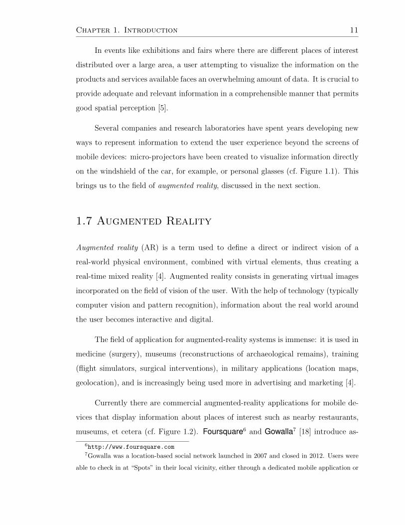
1.7 Augmented Reality
Augmented reality (AR) is a term used to define a direct or indirect vision of a
real-world physical environment, combined with virtual elements, thus creating a
real-time mixed reality [4]. Augmented reality consists in generating virtual images
incorporated on the field of vision of the user. With the help of technology (typically
computer vision and pattern recognition), information about the real world around
the user becomes interactive and digital.
The field of application for augmented-reality systems is immense: it is used in
medicine (surgery), museums (reconstructions of archaeological remains), training
(flight simulators, surgical interventions), in military applications (location maps,
geolocation), and is increasingly being used more in advertising and marketing [4].
Currently there are commercial augmented-reality applications for mobile de-
vices that display information about places of interest such as nearby restaurants,
museums, et cetera (cf. Figure 1.2). Foursquare6 and Gowalla7 [18] introduce as-
6http://www.foursquare.com7Gowalla was a location-based social network launched in 2007 and closed in 2012. Users were
able to check in at “Spots” in their local vicinity, either through a dedicated mobile application or

Chapter 1. Introduction 12
pects of games to social networking applications based on location: a user can find
friends nearby and decide to go see them. The users collect badges or points for
the different places they visit and collect virtual objects, which encourages people to
explore the cities where they live. These software tools work with GPS devices and
compasses to determine the position and orientation. With the location information,
the tool then searches for relevant results that it then displays as an image overlay
on live camera. Some systems such as Urbanspoon8 allow for corrections to the
position by moving a cursor on the map.
Figure 1.2 – The Layar augmented reality application9.
ARToolKit10 is a library that allows the creation of augmented-reality software
in which virtual images are superimposed on the real world. It uses the video
tracking, calculated in real time, and records the camera position and orientation
relative to the position of specific physical markers. Once the real camera position
is known, 3D models can be placed exactly on the marker overlapping the actual
through the mobile website. Checking-in would sometimes produce virtual “items” for the user,
some of which were developed to be promotional tools for the game’s partners.8http://www.urbanspoon.com9http://www.layar.com/
10http://www.hitl.washington.edu/artoolkit

Chapter 1. Introduction 13
object. Thus ARToolKit solves two major problems in augmented reality, tracking
the view and viewing virtual objects.
1.8 Virtual Object Interaction
Being able to see virtual objects raises the question of how to interact which such
objects. The interaction with virtual objects is challenging; often interaction is
performed using physical devices as trackballs or placing markers on the hands or
wearing special gloves. Kolsch proposes the HandVu [31] system of hand signals,
recognized with computer-vision techniques. The system allows the user to interact
with virtual objects (cf. Figure 1.3); the signs used are easy to understand, but
nevertheless not natural gestures. This are not natural gestures in the sense that
are gestures not commonly used by a person in a daily basis, but can be learned.
Figure 1.3 – Handvu virtual object interaction11.
The interactive display developed by the agency The Alternative in the UK
is the window in a department store that allows touch-free interaction using only
the hands moving them in front of the screen. In the Electronic Entertainment
Expo 2009, Microsoft presented the project Natal Xbox 360 (released commercially
as Kinect12 in 2010); this game and entertainment system allows play games and
11http://www.movesinstitute.org/~kolsch/HandVu/HandVu.html12http://www.xbox.com/en-US/KINECT

Chapter 1. Introduction 14
interact with the system using voice commands and recognition of body movements
that are captured by infrared sensors.
1.9 Digital Advertising
Advertising is one of the present-day major ubiquitous computing applications [34].
Currently there are several mobile advertising systems, such as buses or taxis which
change the advertising on their screens depending on the area of the city through
which they pass (cf. Figure 1.4). Advertisers that detect the radio station tuned
in the radios circulating around to show appropriate messages. Other companies
have equipped advertisements with cameras to determine the age and gender of the
viewers and then display the advertisement accordingly.
Figure 1.4 – Digital advertising on a bus that changes depending on the location and
the time of day. (Taken from [34].)
The main problems of digital advertising are the selection of potential clients,
the evaluation of the effectiveness of advertising, and ensuring customer privacy.
Even so, with the combination of elements of mobile computers, tracking systems,
and augmented reality, digital advertising is now possible in scenarios that were
previously impractical.
Take a person who makes purchases in a shopping center. Suppose that the

Chapter 1. Introduction 15
person wants to know where the music store is, and so performs a search on their
smart phone to find out where the store is located. The screen of the smart phone
shows a map of the shopping center, highlighting the location of the store, while
at the same time augmented-reality glasses worn by the user indicate the path to
follow to get there from the current position. While walking through the plaza, the
augmented-reality vision highlights the stores that have products on sale that are
marked on the users shopping list.
When entering the music store, the user receives on the smart phone coupons
and promotions. While spending time in the store, the user receives product sugges-
tions based on previous purchases, as well as recommendations for products acquired
by people in their social network. When finished shopping, the smart phone indi-
cates the mall exit closest to where the user parked the car, again shown both on
map on the device and in an augmented-reality view.
The user has an enhanced shopping experience, and by combining the augmented-
reality glasses with the smart phone, can explore the inside of the mall in a more
natural way than it would using simply the smart phone’s screen, which would re-
quire more of the user’s attention.
In the use case described above, it is also necessary to have an indoor location
systems to determine with accuracy the location of the user within the shopping
mall; by accurately determining the user location, the systems can filter the available
information to display only the relevant information and thus not over-saturate the
user with information that is unnecessary at the time.
1.10 Motivation of the Thesis
Currently there are already some commercial applications of augmented reality for
mobile devices. However, these applications may well be compared to a mobile

Chapter 1. Introduction 16
Google Maps13: they typically display more information than we can see without
using the system, but there is rarely a possibility to interact adequately with the
virtual reality added to the field of vision. The way in which the information is
shown is often through screens of handheld devices and the interaction is carried out
using touch screens or keyboards. Most of the personal-vision systems that currently
exist — such as lenses and headsets — also use keyboards or trackballs to interact
with the system. Moreover, most existing systems that allow natural interaction
with virtual objects are not mobile systems, but rather stationary and specific to a
limited area of interaction such as the interactive screens and the Microsoft Xbox
system using Kinect.
The users who interact with computer systems face different types of inter-
action such as keyboards, mice, trackballs, and monitors. Recognition of gestures
allows to interact with a device free of touch, and if the gestures are natural, with
very small cognitive load as little or no learning is required in the ideal case.
There are currently no systems that combine augmented reality systems on
mobile devices with a natural interaction through hand-based gesture recognition
[36]. One problem for the integration of such systems is the computational capability
of the devices, since the mobile device must be able to handle virtual objects that are
manipulated while performing the gesture recognition to interact with the system.
This is becoming increasingly feasible with the increment in processor speed and
the available memory in smart phones, as well as the higher-resolution screens and
cameras, not to ignore the promise of widely commercializable personal displays of
Google Glass14.
In this work, we study new forms of natural user interaction with a augmented-
reality environment in real time, without the user having to consciously direct at-
tention to the computational device with which the interaction takes place. We also
emphasize the importance of conducting a usability study of the proposed system to
13https://maps.google.com/14http://www.google.com/glass/start/
Chapter 1. Introduction 17
examine the acceptance of users to this kind of technology.
1.11 Thesis Structure
As we are focused on design a new interaction device, it is needed foundations on
how humans perceives and react; in Chapter 2, the fundamentals of cognitive science,
principles and examples on human-computer interaction, and hand-gesture interac-
tion are presented. In the same chapter the computer-vision basics and related work
is discussed. In Chapter 3 our algorithm for hand-gesture recognition is presented,
and in Chapter 4 a prototype for implementing such an algorithm. The experiments
for testing the algorithm performance and the results are presented in Chapter 5.
In Chapter 6 proofs of concept using the algorithm for hand-gesture recognition are
presented, and in Chapter 7 our conclusions and proposals for possible future work
are given.
1.12 Publication
Part of this thesis work was presented with the title “A Tool for Hand-Sign Recog-
nition” [46] at the Mexican Congress on Pattern Recognition (MCPR 2012) held
in Huatulco, Mexico. Proceedings of the conference were published in the Lecture
Notes in Computer Science series by Springer.

Chapter 2
Background
As the thesis is focused on designing and implementing an interaction mechanism,
a foundation of how a human being perceives, reacts, and understands is of essence.
Cognitive science approaches the study of mind and intelligence from an interdisci-
plinary perspective, working at the intersection of philosophy, psychology, artificial
intelligence, neuroscience, linguistics, and anthropology [61].
In this chapter we present the basic concepts about cognitive science, relevant
in the development of new systems.
2.1 Perception
The perceptions is a sensory conscious experience. It occurs when electrical signals
that represent an object in the brain, somehow transform the experience of seeing
the object [26].
Recognition is the ability to locate objects that give them a level of meaningful
status. The process of perception is a sequence of processes that work together to
determine the experience of and reaction to stimuli in the environment. The steps
in this process are the following:
• Environmental stimulus: Stimulus refers to what is out there in the environ-
ment, what one actually pays attention to, and what stimulates the receptors.
The environmental stimulus is all of the things in the environment that one
18

Chapter 2. Background 19
can potentially perceives.
• Attended stimulus: When a person focuses on an object, making it the center
of her attention, it becomes the attended stimulus. The attended stimulus
changes from moment to moment.
• Transduction: Transduction is the transformation of one form of energy into
another form of energy.
• Neural processing: As electrical signals are transmitted through someone’s
retina and then to the brain, they undergo neural processing, which involves
interactions between neurons.
• Perception: Perception is conscious sensory experience. It occurs when the
electrical signals that represent an object are transformed by someone’s brain
into their experience of seeing the object.
• Recognition: Recognition is the ability to place an object in a category.
• Action: Action includes motor activities such as moving the head or eyes and
locomoting through the environment.
• Effects of knowledge: Knowledge is any information that the perceiver brings
to a situation.
The psychophysical approach of the perception focuses on the relationship between
the physical properties of the stimuli and perceptual responses.
The methods used to study the perception psychophysical level are:
• Phenomenological method: The person describes what is perceived.
• Recognition: A stimulus placed in a category.
• Detection: Measurement of the thresholds. The absolute threshold is the min-
imum amount of energy needed to detect a stimulus, the difference threshold
is the smallest difference between two stimuli that are detected.

Chapter 2. Background 20
• Estimated magnitudes: Indicate the qualities of brilliance and volume stimuli.
• Search: Measuring reaction time to find an other stimulus entity.
Light: The Stimulus for Vision
Seeing involves the stimulus and a mechanism that reacts with the light. The vis-
ible light is an energy band within the electromagnetic spectrum that humans can
perceive. Visible light has wavelength ranging from about 400 to 700 nanometers.
The visual process starts once light is reflected from an object into the eye and
is focused onto the retina and the lens forming the image object.
Perception Plasticity
The plasticity is the way in which the stimulus change and mold the perceptual
system. The idea is that the structure and the way the visual system works (or any
other sensorial system) can be mold by experience.
Hebb [27] suggested that repeated experiences, cause the same groups of neu-
rons to fire this shot and strengthens the synaptic connections between neurons.
Learning creates cell gatherings, which are more likely to trigger to a learned stim-
ulus.
Visual Attention
Attention is the process of finding stimuli and subsequent concentration in them. It
is important because it directs the receivers to stimuli that one perceives and also
because it influences the information processing once it stimulates receptors.
Attention can strengthen the perception of stimuli one is focused on and reduce
the awareness of stimuli one ignores. When a person focuses their attention on
something of interest, he or she becomes more aware of what he or she is watching

Chapter 2. Background 21
and less aware of objects or parts of the scene.
Object Perception
The ability to mental organization helps people establish perceptual arrangements.
Gestalt laws [26] of perceptual organization are rules that specify how one organizes
small stimuli into a whole.
• Law of proximity: It occurs when the parts of a whole receive the same stimu-
lus, groups are formed in the direction of the minimum distance occurs auto-
matically.
Figure 2.1 – Law of proximity example. (Taken from [26].)
In the picture there are a number of scattered points, once one recognizes in
them a Dalmatian because one cannot stop seeing it. Previous experience (in
the perception of that form as “Dalmatian dog”) acts potently on conscious
awareness.
• Equality or equivalence act: When a person observe several different kinds of
items, he or she tends to perceive that are equal objects form groups. This
group will depend on the shapes and colors of the elements (most of the time
the color has more weight than the forms).
• Law of good form and common destiny: This helps us to capture the essence
Chapter 2. Background 22
of the forms presented. It allows easy reading of the figures due to different
factors such as destination, synthesis, order, simplicity, et cetera.
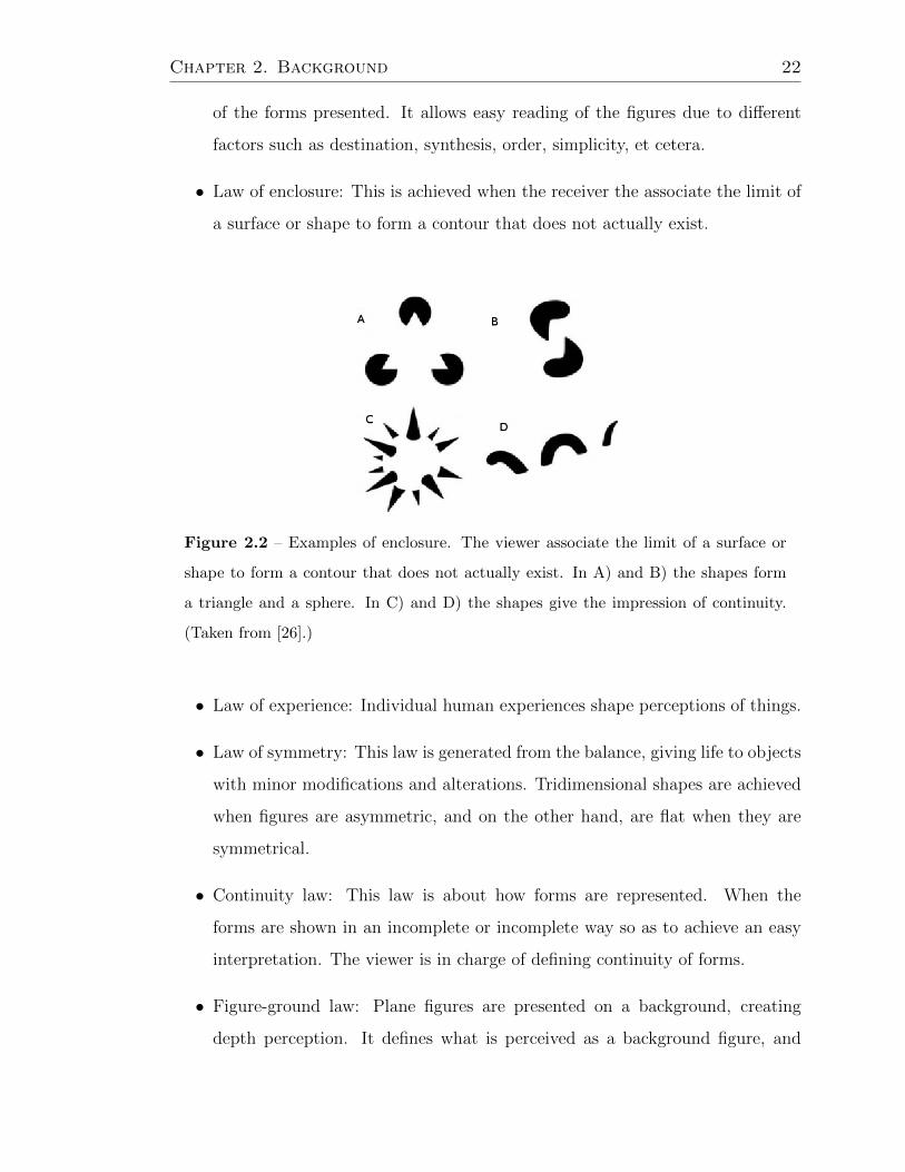
• Law of enclosure: This is achieved when the receiver the associate the limit of
a surface or shape to form a contour that does not actually exist.
Figure 2.2 – Examples of enclosure. The viewer associate the limit of a surface or
shape to form a contour that does not actually exist. In A) and B) the shapes form
a triangle and a sphere. In C) and D) the shapes give the impression of continuity.
(Taken from [26].)
• Law of experience: Individual human experiences shape perceptions of things.
• Law of symmetry: This law is generated from the balance, giving life to objects
with minor modifications and alterations. Tridimensional shapes are achieved
when figures are asymmetric, and on the other hand, are flat when they are
symmetrical.
• Continuity law: This law is about how forms are represented. When the
forms are shown in an incomplete or incomplete way so as to achieve an easy
interpretation. The viewer is in charge of defining continuity of forms.
• Figure-ground law: Plane figures are presented on a background, creating
depth perception. It defines what is perceived as a background figure, and

Chapter 2. Background 23
vice versa. It helps differentiate between the background and shape for easy
perception.
Figure 2.3 – Plane figures are presented on a background; perceiving the white as
background one can see a vase; if the color black is the background, two faces can be
seen. (Taken from [26].)
Color Perception
The color fulfills the function of highlight and facilitates perceptual organization.
One can describe all the colors one see using the terms: red, yellow, green, blue, and
their combinations. The order of the four basic colors in the color circle (cf. Figure
2.4) corresponds to the order of colors in the visible spectrum: at the end of the
shorter wavelength is the color blue, green in the half, red and yellow at the end of
long longwave.
Although the color circle is based on four colors, people can distinguish about
200 different colors throughout the visible spectrum. One may also create other
colors by changing the intensity so that more bright or dim, or adding white, which
contains equal amounts of all wave longitudes to change the color saturation. Chang-
ing the wavelength, intensity, and saturation, it is possible create around a million
different discriminable colors.
The experience of color, as all sensory experiences, is created by the nervous
system. The information on which wavelengths are reflected in the object is encoded

Chapter 2. Background 24
Figure 2.4 – Color wheel.
into neural impulses, which are then transformed into the experience of color. Color
is the way in which the brain knows which wavelengths are present.
The color constancy refers to the way in which perception of color remains
constant even when objects are viewed under different illuminations. The constancy
of brightness refers to the way in which perception remains relatively constant when
objects are viewed in different lighting conditions.
Depth Perception
The key theory of perception is concerned with identifying information of the image
that corresponds to the depth of the scenes. If an object covers part of another,
the object must be partially covered a greater distance than that covering it. This
situation called occlusion is a sign or clue that an object is in front of another.
According to the theory of the keys, one learns the relationship between this key
and depth through the experience and environment. Once learned, the association
between the keys and the depth becomes automatic. These cues can be divided into
three major groups:
1. Oculomotor. Cues based on the ability to sense the position of the eyes and
the tension in the eye muscles.
2. Monocular. Cues that work with one eye.

Chapter 2. Background 25
3. Binocular. Cues that depend on two eyes.
Oculomotor Cues The oculomotor cues are created by convergence, the inward
movement of the eyes that occurs when one looks at nearby objects, and accommo-
dation, the change in the shape of the lens that occurs when one focuses on objects
at various distances.
Monocular Cues Monocular cues work with only one eye. They include pic-
torial cues, which is depth information that can be depicted in a two-dimensional
picture; and movement-based cues, which are based on depth information created
by movement.
• Pictorial cues: Pictorial cues are sources of depth information that can be
depicted in a picture.
• Occlusion: Occlusion occurs when one object hides or partially hides another
from view.
• Relative height: Objects that are below the horizon and have their bases higher
in the field of view are usually seen as being more distant.
• Relative size: When two objects are of equal size, the one that is farther away
will take up less of the field of view than the one that is closer.
• Perspective convergence: When parallel lines extend out from an observer,
they are perceived as converging lines, becoming closer together as distance
increases.
• Familiar size: When one judges distance based on the prior knowledge of the
sizes of objects.
• Atmospheric perspective: Atmospheric perspective occurs when more distant
objects appear less sharp and often have a slight blue tint.
Chapter 2. Background 26
• Texture gradient: Elements that are equally spaced in a scene appear to be
more closely packed as distance increases.
• Shadows: Shadows that are associated with objects can provide information
regarding the locations of these objects.
• Motion parallax: Motion parallax occurs when, as one moves, nearby objects
appear to glide rapidly past the observer, but more distant objects appear to
move more slowly.
• Deletion and accretion: As an observer moves sideways, some things become
covered, and others become uncovered.
Binocular Cues There is one other important source of depth information: the
differences in the images received by the two eyes. Binocular disparity is the differ-
ence in the images in the left and right eyes.
Size Perception
The depth perception influences the perception of size. A good depth perception
produces accurate judgments of size and produces bad judgments based on the size
of the visual angle of the object. Examples of perception of size-dependent visual
angle perception are the sun and the moon and the way one perceives objects from
a plane. The principle of size constancy holds that the perception of the size of an
object remains relatively constant even when viewed from different distances.
Motion Perception
Motion perception is a creation of the nervous system. People perceive motion even
in the absenceof it, as when fixed lights go on and off alternately. Visual perception
depends on more than one image on the retina. One observer perceives motion when
follows a moving object, but the image remains in the same place in the retinas.

Chapter 2. Background 27
Movement of the observer and the movement of objects can help to more
accurately perceive the shape of an object and its location in space. Perception
depends on heuristics that provide estimates of what a particular stimulus. The
real movement is the situation where an object moves across the visual field of the
observer, is called real movement because the object moves physically. The apparent
motion is the perception of movement when in fact there are two separate lights that
turn on and off alternately. This apparent motion perception depends on the time
between the two flashes.
Interval
Less than 30ms
Between 30 and 60 ms
Starts at about 60 ms
More than 200 or 300 ms
Perception
Simultaneous
(motionless)
Partial movement
Ilussion of movement
Succesive
(motionless)
Figure 2.5 – Motion perception.
Silencing
Silencing demonstrates the close connection between the movement and the appear-
ance of the object. Simply moving the object or the eyes can mute visual changes,
making objects that had been dynamic suddenly appear static1.
1http://visionlab.harvard.edu/silencing/

Chapter 2. Background 28
Perception and Action
The ecological approach to perception deals with the study of perception as it oc-
curs in the natural environment. This approach emphasizes the connection between
perception and action. The environmental information is the starting point for the
analysis of this perception. The movement forms an important source of environ-
mental information.
The optical order is the optical structure of the environment in some extent. In
the static optical order, information exists, but it is possible to get more information
through the movement of the observer because it generates optical flow.
The way in which visual information is used to catch a high ball probably
suggest that people do not make complex calculations to determine its future course
of action, but uses visual information that occurs by itself in a way that creates
movements synchronized with current perceptions.
Vision is not the only sense involved in the coordination between perception
and action, hearing may also be involved.
Perception Biased by Experience
Expectations, and therefore perceptions, are biased by three factors:
• The past: the experience,
• This: the current context,
• The future: the goals.
In Figure 2.6, when the sensing system is prepared to see forms of construction, the
observer only sees forms of construction and the white areas between buildings are
barely recorded in perception. When the perception system has been prepared to see
text, the observer sees the text, and the black areas between letters barely register.

Chapter 2. Background 29
Figure 2.6 – Example of perception biased by experience: When the system was
prepared to see forms of construction, one see forms of construction and the white
areas are barely recorded, even when they form the word “LIFE”. (Taken from [61].)
Software users and websites often click the buttons or links without looking
closely at them. The perception of the display is based more on what their experience
leads them to expect that what is actually on the screen. This sometimes confuses
software designers, who expect users to see the availability of the screen. But that
is not how perception works. For example, if the positions of the buttons “Next”
and “Return” located on the last page of a dialog box changes, many people do not
immediately notice the change.
Proximity
The proximity principle has obvious relevance to the disposition of the control panels
or data in software, websites and electronic applications. Designers often separate
groups of controls and data display grouping them in boxes or by placing lines
between groups. According to the principle of proximity, the elements on a screen
can be visually grouped simply by the spacing between them, putting them closer
to each other than to other controls, or group boxes without visible borders [30].
Experts recommend this approach to reduce visual clutter of a user interface.
Conversely, if the controls are too far, people have trouble perceiving that are related,
so the software is more difficult to learn and remember. Another factor that affects
the perception of the grouping is expressed is the principle of similarity: objects that

Chapter 2. Background 30
Figure 2.7 – Example of perception biased by experience: if the positions of the
buttons “Next” and “Return” change, many people do not immediately notice the
change. (Taken from [61].)
seem similar are grouped.
Figure 2.8 – Example of proximity: the elements on a screen can be visually grouped
using borders or putting them closer (screen capture of the Granola2 software).
2http://grano.la/

Chapter 2. Background 31
Figure vs. Ground
In web design and user-interface design, the principle of figure versus ground is often
used to direct primary attention to specific content. The background can convey
a theme or mood to guide the interpretation of the content. Figure vs. ground is
also often used to display information about the content. Content that was once
the figure, temporarily becomes the background of new information, which appears
briefly as the new figure.
This approach is generally best to temporarily replace the old information with
new information as it provides a context that helps keep people focused in their place
in the interaction.
Figure 2.9 – Example of figure vs. ground (screen capture of Google Chrome).
Text
Even when the vocabulary is familiar, reading may be interrupted by writings and
fonts hard to read. Context-free, automatic reading is based on recognition of letters
and words by their visual characteristics. Therefore, a font with features and forms
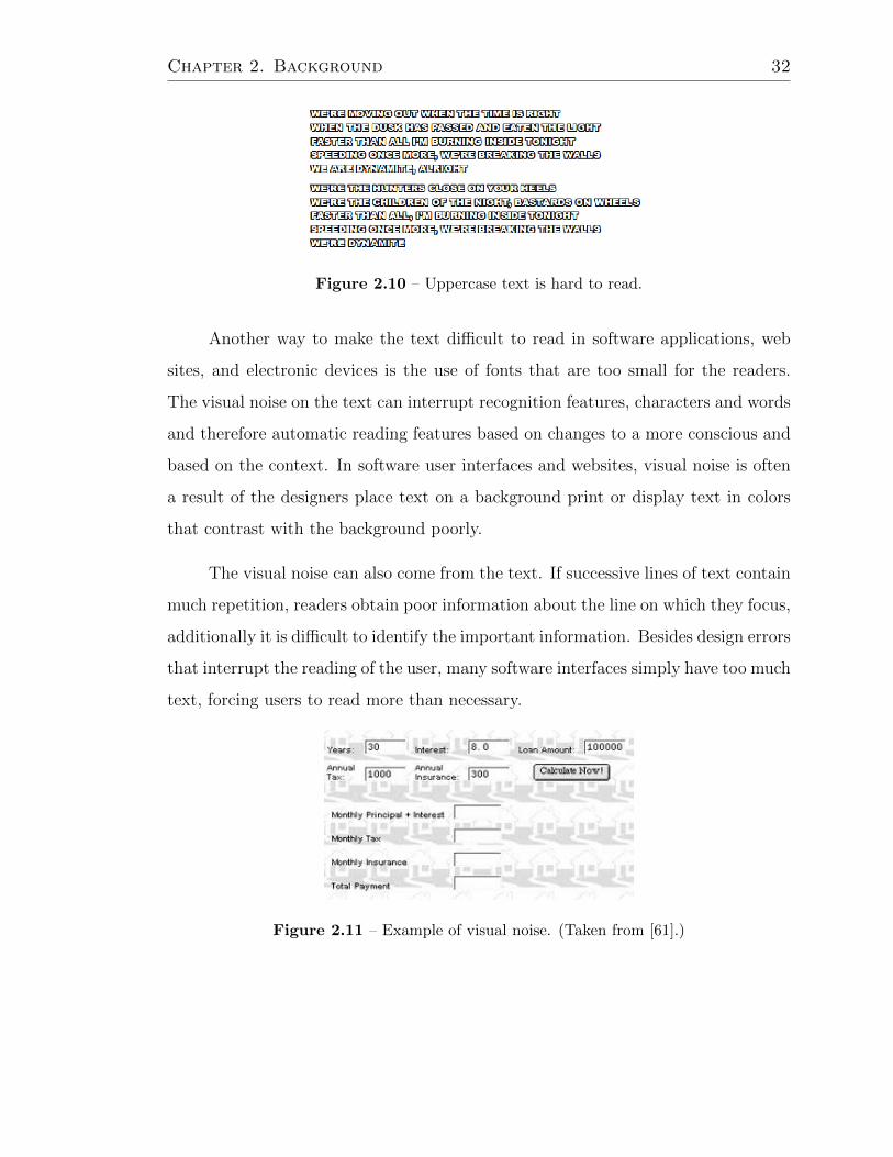
difficult to recognize it will be hard to read. Uppercase text is often hard to read
because the letters seem similar. Outline fonts feature make recognition of text
complicated.
Chapter 2. Background 32
Figure 2.10 – Uppercase text is hard to read.
Another way to make the text difficult to read in software applications, web
sites, and electronic devices is the use of fonts that are too small for the readers.
The visual noise on the text can interrupt recognition features, characters and words
and therefore automatic reading features based on changes to a more conscious and
based on the context. In software user interfaces and websites, visual noise is often
a result of the designers place text on a background print or display text in colors
that contrast with the background poorly.
The visual noise can also come from the text. If successive lines of text contain
much repetition, readers obtain poor information about the line on which they focus,
additionally it is difficult to identify the important information. Besides design errors
that interrupt the reading of the user, many software interfaces simply have too much
text, forcing users to read more than necessary.
Figure 2.11 – Example of visual noise. (Taken from [61].)

Chapter 2. Background 33
2.2 Memory
Memory is the processes by which information is encoded, stored, and retrieved.
Encoding allows information that is from the outside world to reach the senses in
the forms of chemical and physical stimuli. In this first stage one must change the
information so that one may put the memory into the encoding process. Storage is
the second memory stage or process. This entails that one maintains information
over periods of time. Finally the third process is the retrieval of information that
one has stored. One must locate it and return it to the consciousness. Some retrieval
attempts may be effortless due to the type of information.
Short and Long Term Memory
Recent research on memory function and brain indicate that short term memory and
long term are functions of a single memory system one that is more closely linked
to the perception of what is thought. The memory formation involves long-lasting
changes even permanent in neurons involved in a pattern of neural activity, making
it easier to reactivate the pattern in the future.
The memory activation is reactivate the same pattern of neuronal activity that
occurred when the memory was formed. Somehow the brain distinguishes initial
activations and reactivation of neural patterns. The more often a pattern of neural
memory is reactivated, the stronger it gets; that is, it becomes easier to revive, which
in turn means that the corresponding perception is easier to recognize and remember.
The short-term memory, is equal to the center of the attention. The main features
of the short-term memory are its low capacity and volatility. The capacity and the
volatility of short-term memory has many implications for the design of interactive
computer systems. The main consequence is that user interfaces should help people
remember the essential information at any moment.
People do not require to remember the state of the system or what they did,

Chapter 2. Background 34
because their attention is focused on the main goal and progress towards it. For
example when people use a search function on a computer to find information, write
the search terms, the search begins, and then review the results. The evaluation of
results often requires knowing what were the search terms. If short-term memory
is not limited, people always remember what they had written in search terms just
a few seconds earlier. When the results appear, the attention of the individual is
directed away from what he is looking towards the outcome. Not surprisingly, people
who see search results often do not remember the search terms they just typed.
Figure 2.12 – The reservation system of an airline shows the progress of the user to
know at what stage the process is3.
It Is Easy To Recognize, It Is Hard to Remember
The relative ease with which one can recognize things rather than recall is the basis
of the graphical user interface (GUI). Graphical user interface is based two rules of
interface design:
• See and choose is easier to remember and type: Show users their choices and let
them choose between them, rather than forcing users to remember the options
and tell the system what they want. This rule is the reason why the GUI
almost completely replaced by the command-line user interface in personal
computers.
• Use images whenever possible to transmit function: People recognize images
very quickly, and recognition of an image also stimulates recovery of associated
3http://www.aeromexico.com/

Chapter 2. Background 35
information. For this reason, the user interfaces are used to transmit images
function as desktop icons or toolbar, error symbols, and plot options to know
what stage of the process is.
Figure 2.13 – Using icons to recognize items on a menu (screen capture of Word-
press4).
2.3 Learning
Learning is acquiring new, or modifying existing, knowledge, behaviors, or skills
and may involve synthesizing different types of information. The ability to learn is
possessed by humans, animals, and some machines. Learning is not compulsory, it
is contextual. It does not happen all at once, but builds upon and is shaped by what
one already knows. Learning may be viewed as a process, rather than a collection
of factual and procedural knowledge.
Problem Solving and Calculation are Difficult.
People have their own objectives. They are using a computer to help them achieve
a goal. They want and need to focus their attention on that goal. Interactive
system designers should respect that and not distract users by imposing technical
problems and objectives that users do not want. Examples of technical problems
that computers and web services impose on their users include the following:
4http://wordpress.com/

Chapter 2. Background 36
• I want my “ID”. Is that the same as my username?.
• I was charged full price! It did not gave me my discount. Now what?
• It says the software can be incompatible with a plugin already on my PC.
“May be”? Is it or is not it? And if so, which plugin is guilty? What should I
do?
• I want the page numbers in chapter start in 23 instead of 1, but I don’t see
a command to do that. I have tried page setup, document structure, and the
view of header and footer, but it is not there. All that remains is to insert
page numbers. But I do not want to insert page numbers: the chapter already
has page numbers. I just want to change the starting number.
• This box is checked: “Align icons horizontally”. If you disable it, will my icons
are aligned vertically, or simply do not align?
Interactive systems must minimize the amount of attention that users must spend
to operate, because it attracts cognitive resources away from the task that the user
wants to do on the computer. Some design rules are:
• Indicate system status and progress of the users towards the goal.
• Guide users towards their goals.
• Instruct users exactly and explicitly what they need to know.
• Do not make users to diagnose system problems.
• Minimize the number and complexity of the configuration.
• Ask the user to use the perception more often that the calculation.
• Make the system familiar.
• Let the computer do the math.

Chapter 2. Background 37
Factors Affecting Learning
People learn faster under the following conditions: first the operation is focused
on the task, simple and consistent; second the vocabulary is focused on the task-
centered, familiar and consistent. The risk is low: for software design, designers
must thoroughly understand user goals and tasks for which the tool is designed.
Achieving this understanding requires three steps:
1. Perform a task analysis
2. Design a conceptual model focused on the task, which consists mainly of an-
alyzing objects/actions. A conceptual model should be as simple as possible.
Simpler means less concepts. The less has a user concepts to master, the better,
always providing the required functionality. Less is more, with the condition
that what is there fits perfectly with the goals of users and tasks.
The consistency of an interactive system strongly affects how the user quickly
progresses from a slow operation consciously monitored an automatic with
faster performance. The more predictable operation of the various functions
of the system is, the more consistent is the design.
3. Design a user interface based strictly on task analysis and conceptual model.
2.4 Cognitive Psychology
Cognitive psychology is the branch of psychology that studies mental processes in-
cluding how people think, perceive, remember, and learn. The core focus of cognitive
psychology is on how people acquire, process, and store information. Cognition in-
volves all processes by which the sensory input is transformed, reduced, elaborated,
stored, recovered, and used.

Chapter 2. Background 38
Mental Models and Implementation
An implementation model (also called system model) is a representation of how a
machine actually works or program. A mental model or a conceptual model is as
a user imagines that the system works. For example, a person may believe that
connecting an appliance to a power electric current flows through the cable as water
in a hose.
People do not need to know exactly how a complex mechanism to use it, so
they create cognitive representations to explain. These representations are sufficient
to cover the interactions with the system, but not necessarily the functioning of the
internal mechanism. In the case of software applications the differences between
mental models of implementation and are very subtle, this is because the complex-
ity makes it almost impossible for the user to see the connections between their
actions and reactions of the program. Even if these connections are visible, they are
inexplicable to most people.
A third model is the model represented designer or model, that is the way
the designer chooses to represent the functionality of the program to the user. This
representation can be or not be an accurate representation of what happens within
the program. People tend to form mental models that are simpler than reality, if
the designer’s represented models that are simpler than the implementation model
to help users better understand. User interfaces must be based on mental models
rather than the implementation models. The more one looks the model represented
the mental model is easier for the user to use and understand the system.
For example, the program Photoshop Express (cf. Figure 2.15) uses images to
show different effects on an image, a user of this program, usually a graphic artist, is
thinking about how the image will not think in abstract numbers as the brightness
value or color saturation. A user’s mental model need not be necessarily true or
accurate, but should allow it to work effectively.

Chapter 2. Background 39
Figure 2.14 – Mental models. (Taken from [11].)
Figure 2.15 – Using images to recognize items on a menu (screen capture of Photo-
shop Express5).
Experience Levels
Most users are not beginners or experts, but intermediate. Although all users spend
some time as starters, nobody stays that way for long. People do not like being
incompetent, novice users become intermediates quickly or leave, no one wants to
stay forever as a beginner. Most intermediate users remain in this middle state
because they have more time to learn more about the product. Sometimes they use
it just to complete a project, and then stop using it for months, forgetting much of
what they learned. One should optimize designs for intermediate users: the goal is
to turn quickly and effortlessly beginners on intermediate users, and avoid obstacles
for those who want to become experts.
• Needs of beginners: A designer should consider beginners as highly intelligent
and very busy, but not requiring too much instruction; the process should be
5http://www.photoshop.com/tools/expresseditor

Chapter 2. Background 40
Figure 2.16 – Experience levels. (Taken from [30].)
fast and focused. People learn best when they understand the cause and effect
of how things work.
• Expert needs: Users constantly looking to learn connections between their
actions and the behavior of the product. Experts appreciate powerful new fea-
tures. Experts call for quick access to regular working tools and want shortcuts
for everything.
• Intermediate needs: Intermediate users need easy access to the tools, do not
need to be explained because they already know how they work. Tooltips
are perfect for intermediate user. The user will demand that work tools are
located on the front and center of the interface, easy to find and remember.
Intermediate users also know that there are advanced features but do not need
them or not use them.
Platform and Posture
A platform is a combination of hardware and software that allows a product to work,
in terms of user interaction and internal operations of the product. “Platform” is
not a well-defined concept; it describes a number of important product character-
istics such as physical form, size, and display resolution, input method, network

Chapter 2. Background 41
connectivity, operating system, and database capabilities.
Platforms range from desktop software, websites, vehicle systems, cameras,
phones, PDAs, televisions, medical equipment, scientific instruments, et cetera. To
choose the right platform should be able to find a balance between the context and
needs of people in addition to complying with the business restrictions, objectives
and technological capabilities.
Posture is the way the product is self-presented to the users. It refers to how
much attention a user requires to interact with a product and how it responds. How
presented a program affects the relation between users and the product usability. If
the appearance and behavior conflicts with their product seem inappropriate pur-
poses. The appearance and behavior of the product should reflect the way is used,
instead of the personal tastes of the designers, any aesthetic decision must be in har-
mony with the position of the product. When a product has different characteristics
and different postures, the prevailing posture must be defined, but also consider the
posture and context of individual characteristics.
Desktop Software
The term desktop software refers to all applications running on a PC. Desktop ap-
plications are divided into several positions: sovereign, transitory, and daemonic.
• Sovereign posture: The programs are monopolizing the user’s attention for
long periods of time. They offer a wide range of functions and features, users
kept running continually and occupy the entire screen. For example: words
processors, spreadsheets, e-mail applications. Sovereign application users are
usually intermediate users. Applications must be optimized for use sovereign
full screen. They should use conservative colors.
• Transient posture: The program comes and goes, accompanied by filing a
simple function of a restricted set of controls, the application is invoked when

Chapter 2. Background 42
you need the job done quickly and then disappears by continuing the user
to continue with normal activity, usually a sovereign application, for example
widgets. The interface should be obvious, presenting clearly controls without
confusion or mistakes. It should be simple and clear with large easy to read
buttons. It must respect the sovereign application and not occupy more screen
space than necessary. The program should be limited to a simple window. A
transient application must remember its previous position and configuration.
• Daemonic posture: Programs run silently in the background, invisible, per-
forming vital tasks without human intervention. For example printer drivers,
networking. Occasionally demonic applications need to be adjusted, so that
they become transient.
2.5 Designing Interfaces
Following user-interface design guidelines is not straightforward. Design rules often
describe goals rather than actions. They are purposefully very general to make them
broadly applicable, but that means that their exact meaning and their applicability
to specific design situations is open to interpretation. More than one rule will often
seem applicable to a given design situation. In such cases, the applicable design
rules often conflict, i.e., they suggest different designs. All of the design rules are
based on human psychology: how people perceive, learn, reason, remember, and
convert intentions into action. Many authors of design guidelines had at least some
background in psychology that they applied to computer system design [61].
Web sites
Web sites can be divided in two different categories: transactional sites and web
applications.
Transactional sites include online shopping, banking, investment portals. Dur-
Chapter 2. Background 43
ing these activities users devote their attention to a single site, but in some cases,
such as comparing products to buy, also jump between different sites, so it is impor-
tant to clarify this in navigation.
Web applications include enterprise applications, publishing tools, and online
documents. These applications can be presented as desktop applications that run
within a browser window. These applications require the user to save each state
change.
Design on Other Platforms
The platforms include: kiosks, televisions, microwave ovens, car dashboards, cell
phones, et cetera. Some basic principles to consider when designing software for
these platforms include the following:
• Do not think of the product as a computer.
• Integrate hardware and software design.
• Let the context guide the design.
• Use different ways to view.
• Limit the scope.
• Balance the navigation display.
• Adapt to the platform.
Flow and Transparency
Flow is the state when a person is able to focus on an activity, losing awareness of
peripheral problems and distractions. To make people more productive and happy,
corresponds designing interactive products to promote and improve the flow. If
the application user distracts and disrupts the flow, it is difficult to maintain the

Chapter 2. Background 44
productive state. If the user can achieve his or her goals without the need for the
product or user interface, then he or she will. Interaction with excess software will
never be a pleasant experience. No matter how great is the interface, less is always
better.
To create a sense of flow, the interaction must be transparent, mechanics dis-
appearing and leaving the person face to face with the objectives. Some rules for
designing harmonious interactions:
• Follow the user’s mental model.
• Less is more.
• Allow users to conduct.
• Keep tools handy.
• Provide feedback.
• Desig for the probable, provide for the possible.
• Provide comparisons.
• Provide direct manipulation.
• Reflect the status of the application and objects.
• Avoid unnecessary reporting.
• Avoid blank screens.
• Differentiate between commands and settings.
• Provide options.
• Hide the “emergency levers”.
• Optimize for the answer.

Chapter 2. Background 45
Extra Load
Extra load is the work that one has to do to meet the needs as tools or external
agents as while trying to reach the goal. It is difficult to distinguish because people
are used to see the extra load as part of the tasks. A designer must aim to delete
the extra load whenever possible. Designers often add extra load as support for
first-time users or casual. These tools become burden as users become more familiar
with the product. Wizards and tutorials should be able to be turned off easily.
Visual extra load causes waste of time when the user is trying to find an item on
a list or determining which elements are buttons and which are decoration. Another
way of extra load are interruptions, such as error messages, whenever possible, to
avoid interrupting the flow of the user. Asking permission from users to make a
change, or open a new window to make the change, it is also extra burden; it should
be possible to make and save changes in the same place. Navigation is also an extra
burden, should be avoided whenever possible. To improve navigation, the designer
should:
• Reduce the number of places to go.
• Provide signs.
• Provide global views.
• Provide a suitable mapping.
• Avoid hierarchies.
Design of Good Behavior
The division of labor in the computer age is very clear: “the computer should do
the job and the person should think” [61]. One should think of the computer as
a co-worker with whom one has a good working relationship. Computers must be

Chapter 2. Background 46
considerate, that is, worried about the needs of others. A considerate software cares
about the objectives and user needs.
If an interactive product hides its processes, forces users to find the common
features, and the user blame for failures, and users will have an unpleasant and
unproductive experience. Users of interactive products are commonly irritated due
the lack of consideration, not poor specifications. Some of the important rules for
interactive product design are:
• Have an interest.
• Be respectful.
• Use common sense.
• Anticipate user needs.
• Do not load the user with personal problems.
• Keep the user informed.
• Be perceptive.
• Trust.
• Do not ask too many questions.
• Take responsibility.
• Know when to bend the rules.
Intelligent Product Design
Smart products remember. In order how the user perceives an interactive product
as considerated and intelligent, the product must have some knowledge about the
user and learn from their behavior. A product must learn important things when a
user interacts with:

Chapter 2. Background 47
• Recall decisions.
• Remember patterns.
• File locations.
• “Undo” lists.
• Previous data inputs.
• Reduction of joint decisions: The product should reduce frequently used deci-
sions to the option of do it all at once.
• Prefered thresholds: A smart product should remember thresholds used pre-
viously by the user, to avoid adjustment of preferences every time the product
is used.
Metaphors
There are three paradigms on the visual design of interfaces:
• Focused on implementing: Interfaces based on understanding how things really
work.
• Metaphor: Interfaces based on intuition of how things work.
• Idiomatic: Interfaces based on learning how to reach a goal.
Some designers think that filling the interface with familiar images and objects
from the real-world to help users learn more easily. Top designers consider the selec-
tion of metaphor as the first and most important task. The problem of metaphors is
that there are not enough, they do not scale well, the ability of users to recognize is
questionable, and that there are cultural barriers. It is important for the designers
never to make the interface take the form of a metaphor.

Chapter 2. Background 48
2.6 Human-Computer Interaction
Human-device interaction is designed to support explicit human-computer interac-
tion which is expressed at a low level, e.g., to activate particular controls in this
particular order. As more tasks are automated, the variety of devices increases and
more devices need to interoperate to achieve tasks. The amount of explicit interac-
tion can easily disrupt, distract, and overwhelm users. Interactive systems need to
be designed to support greater degrees of human-computer interaction.
2.6.1 Vision-Based Interfaces
The use of the hand as an input device is a method that provide natural human-
computer interaction (HCI). Computer-vision interaction is a natural, non-contact
solution, but has some limitations. Computer vision can only provide support for
a small range of hand actions under restrictive conditions. The hand gestures used
in existing real-time systems are limited to a vocabulary of gestures that serve as
simple commands. There have been considerable efforts to use the hand as an input
device for human-computer interaction however, hand-pose estimation is still a big
challenge in computer vision. There are still several open problems to be solved in
order to obtain robustness, accuracy, and high processing speed. The existence of
an inexpensive but high speed system is quite encouraging.
Virtual environments (VEs) should provide effective human computer inter-
action for applications involving complex interaction tasks. In these applications,
users should be supplied with sophisticated interfaces allowing them to navigate in
the virtual environment, select objects, and manipulate them. Implementing such
interfaces raises challenging research issues including the issue of providing effective
input/output. Computer vision has a distinctive role as a direct sensing method be-
cause of its non-intrusive, non-contact nature; it is also facing various challenges in
terms of precision, robustness and processing speed requirements. Various solutions

Chapter 2. Background 49
have been proposed to support simple applications based on gesture classification.
HandVu is a hand-sign vision-based recognition system that allows to interact
with virtual objects. However, the used signs, although easy to understand, are not
natural gestures. Finger Counter [12] is a simple human-computer interface. Using
a webcam, it interprets specific hand gestures as input to a computer system in real
time. The UbiHand [1, 2] is an input device that uses a miniature wrist-worn camera
to track finger position, providing a natural and compact wearable input interface.
A hand model is used to generate a 3D representation of the hand, and a gesture
recognition system can interpret finger movements as commands. The system is a
combination of a pointer position and non-chorded keystroke input device that relies
on miniature wrist-worn wireless video cameras that track finger position.
An interactive screen developed by The Alternative Agency in UK is located in
a department store window. The Orange screen 6 allows interaction only by moving
the hands in front of the window without the need to touch it.
Sixthsense [42] is a system that converts any surface in an interactive surface.
In order to interact with the system, hand-sign recognition is used. In the Sixthsense
system, color markers are used in the fingers to detect the signs.
Lately it has generated great interest in the area of human-computer interac-
tion to create more user-friendly interfaces that use natural communication. These
interfaces allow the development of a large number of sophisticated applications like
virtual environments or augmented reality (AR) systems. Development of these
systems involves a challenge in the research of effective inout/output techniques,
interaction styles, and evaluation methods [19].
Hirobe et al. [60] have created an interface for mobile devices using image
tracking. The system tracks the finger image and allows to type on an in-air keyboard
and draw 3D pictures. Stergiopoulou et al. [56] use self-growing and self-organized
neural networks for hand-sign recognition.
6http://www.thealternative.co.uk/

Chapter 2. Background 50
Skin color is a common method for locating the hand because of its fast im-
plementation. Skin color filters use the assumption that the hand is the only skin-
colored object. Gesture classification is a research field involving many machine
learning techniques for example: Neural Networks and Hidden Markov Model. Pose
estimation involves extracting the position and orientation from the hand, fingertip
locations, and finger orientation from the images.
Currently, computer vision-based interaction has some limitations in processing
arbitrary hand actions. Computer vision can only provide support for a small range
of hand actions under restrictive conditions. This approach has certain drawbacks in
terms of natural interaction requirements. The hand gestures used in existing real-
time systems are limited to a vocabulary of gestures that serve as simple commands.
Hand-pose estimation is still a big challenge in computer vision. Pose restric-
tions and the lack of an implementation in a real-world application indicate that
there are still numerous open problems to be solved in order to obtain robustness,
accuracy, and high processing speed.

Chapter 2. Background 51
2.6.2 Hand-Gesture Interaction
The use of the hand as an input device is a method that provide natural human-
computer interaction (HCI). Computer-vision interaction is a natural, non-contact
solution, but has some limitations. Computer vision can only provide support for
a small range of hand actions under restrictive conditions. The hand gestures used
in existing real-time systems are limited to a vocabulary of gestures that serve as
simple commands.
There have been considerable efforts to use the hand as an input device for
human-computer interaction, however hand pose estimation is still a big challenge
in computer vision. There are still numerous open problems to be solved in order
to obtain robustness, accuracy, and high processing speed. The inexistence of an
inexpensive but high-speed system is quite encouraging.
Virtual environments should provide effective human-computer interaction for
applications involving complex interaction tasks. In these applications, users should
be supplied with sophisticated interfaces allowing them to navigate in the virtual
environment, select objects, and manipulate them. Implementing such interfaces
raises challenging research issues including providing effective input/output.
Computer vision has a distinctive role as a direct sensing method because of
its non intrusive, non-contact nature; it is also facing various challenges in terms
of precision, robustness and processing-speed requirements. Various solutions have
been proposed to support simple applications based on gesture classification.
2.6.3 Vision-Based Pose Estimation
Lately it has generated great interest in the area of human-computer interaction
to create more user-friendly interfaces that use natural communication. These in-
terfaces allow the development of a large number of sophisticated applications like
virtual environments or augmented-reality systems. Development of these systems

Chapter 2. Background 52
involves a challenge in the research of effective input/output techniques, interaction
styles, and evaluation methods [19].
Skin color is a common method for locating the hand because of its fast im-
plementation. Skin-color filters use the assumption that the hand is the only skin-
colored object. Pose estimation involves extracting the position and orientation from
the hand, fingertip locations, and finger orientation from the images.
2.6.4 Gesture-Based Interaction Systems
Hirobe et al. [29] have created an interface for mobile devices using image tracking.
The system tracks the finger image and allows to type on an in-air keyboard and
draw 3D pictures (Figure 2.17).
Figure 2.17 – In-air typing interface of Fastfinger [60].
Stergiopoulou et al. [56] use self-growing and self-organized neural networks for
hand-sign recognition. Finger Counter [12] is a simple human-computer interface.
Using a webcam, it interprets specific hand gestures as input to a computer system
in real time.
The UbiHand [2] is an input device that uses a miniature wrist-worn camera
to track finger position, providing a natural and compact wearable input interface.

Chapter 2. Background 53
A hand model is used to generate a 3D representation of the hand, and a gesture-
recognition system can interpret finger movements as commands. The system is
a combination of a pointer position and non-chorded keystroke input device that
relies on miniature wrist-worn wireless video cameras (Figure 2.18) that track finger
position [1].
Figure 2.18 – UbiHand wrist-worn input device [2].
HandVu is a hand-sign vision-based recognition system that allows to inter-
act with virtual objects (Figure 2.19). However the used signs, although easy to
understand, are not natural gestures and have to be memorized.
Figure 2.19 – The signs used in the Handvu system are not natural gestures7.
An interactive screen developed by The Alternative Agency8 in UK is located
in a department store window (Figure 2.20). The Orange screen allows interaction
7http://www.movesinstitute.org/~kolsch/HandVu/HandVu.html8http://www.thealternative.co.uk/

Chapter 2. Background 54
only by moving the hands in front of the window without the need to touch it.
Figure 2.20 – The world’s first touchless interactive shop window9.
Sixthsense [42] is a system that converts any surface in an interactive surface.
In order to interact with the system, hand-sign recognition is used (Figure 2.22). In
the Sixthsense system, color markers are used in the fingers to recognize the signs
(Figure 2.21).
Figure 2.21 – The Sixthsense system uses a camera and a projector to convert any
surface in an interactive surface [42].
Advantages and disadvantages of some related work on hand recognition are
show on Table ??.
9http://www.thealternative.co.uk/.

Chapter 2. Background 55
Figure 2.22 – Hand signs used in the Sixthsense system [42].

Chapter 2. Background 56
Table
2.1
–R
elat
edw
ork
onh
and
reco
gnit
ion
2001
–200
4.
Au
thor
Yea
rT
itle
Ap
pli
cati
on
Met
hod
Ad
vanta
ges
Dis
ad
vanta
ges
Wu
[73]
2001
Cap
turi
ng
Nat
ura
lH
an
d
Art
icu
lati
on
Han
d-p
ose
reco
gn
itio
n
Seq
uen
tial
Monte
Carl
o
Rob
ust
an
d
acc
ura
te
Som
em
oti
on
s
not
con
sid
ered
Lin
[38]
2002
Cap
turi
ng
Hu
man
Hand
Moti
on
in
Imag
eS
equ
ence
s
Han
d-p
ose
esti
mati
on
Iter
ati
veC
lose
dP
oin
t
(IC
P)
alg
ori
thm
,
Monte
Carl
o
Acc
ura
tean
d
rob
ust
Image
sequ
ence
s
Lu
[39]
2003
Usi
ng
Mu
ltip
leC
ues
for
Han
d
Tra
ckin
gan
dM
od
elR
efin
emen
t
Han
d-p
ose
esti
mati
on
Gra
die
nt-
base
dop
tica
l
flow
con
stra
int,
forw
ard
recu
rsiv
e
dyn
am
icm
od
el
Diffi
cult
han
d
moti
on
san
d
con
dit
ion
s
Sin
gle
cam
era
sequ
ence
Cra
mp
ton
[12]
2003
Cou
nti
ng
Fin
gers
inR
eal
Tim
e:A
Web
cam
-Bas
edH
um
an
-Com
pu
ter
Inte
rfac
ew
ith
Gam
eA
pp
lica
tion
s
Com
pu
ter
gam
es
Back
gro
un
d-
diff
eren
cin
g
alg
ori
thm
Work
sw
ith
web
cam
Few
han
d
post
ure
s
Ste
nge
r[5
5]20
04H
and
-pos
eE
stim
atio
nU
sin
g
Hie
rarc
hic
alD
etec
tion
Han
d-p
ose
esti
mati
on
Tre
e-b
ase
dd
etec
tion
Easy
to
gen
erate
Bad
per
form
an
ce
Su
dd
erth
[59]
2004
Vis
ual
Han
dT
rack
ing
Usi
ng
Non
par
amet
ric
Bel
ief
Pro
pagati
on
Han
d-p
ose
esti
mati
on
Non
para
met
ric
bel
ief
pro
pagati
on
(NB
P)
alg
ori
thm
Eff
ecti
veh
an
d
track
ing
alg
ori
thm
Image
sequ
ence
s
Dew
aele
[16]
2004
Han
dM
otio
nfr
om3D
Poin
t
Tra
ject
orie
san
da
Sm
ooth
Su
rface
Mod
el
Han
d-p
ose
esti
mati
on
Mix
edp
oin
t-to
-poin
t
an
dm
od
el-b
ase
d
track
ing
3D
mod
els
Ste
reosc
op
icse
t
of
cam
eras

Chapter 2. Background 57
Table
2.2
–R
elat
edw
ork
onh
and
reco
gnit
ion
2004
–200
9.
Au
thor
Yea
rT
itle
Ap
pli
cati
on
Met
hod
Ad
vanta
ges
Dis
ad
vanta
ges
Bra
y[7
]20
04S
mar
tP
arti
cle
Fil
teri
ng
for
3D
Han
dT
rack
ing
Han
d-g
estu
re
reco
gn
itio
n
Sto
chast
ic
Met
a-D
esce
nt
(SM
D),
smart
part
icle
sfi
lter
Rob
ust
nes
san
d
acc
ura
cy
Slo
w
Usa
bia
ga[6
2]20
05G
lob
alH
and
Pos
eE
stim
ati
on
by
Mu
ltip
leC
amer
aE
llip
seT
rack
ing
Han
dp
ose
esti
mati
on
Low
e’s
mod
el-b
ase
d
pose
esti
mati
on
alg
ori
thm
More
acc
ura
te
an
dro
bu
st
Mu
ltip
le
cam
eras
,m
ark
Ah
mad
[1]
2006
AK
eyst
roke
and
Poin
ter
Contr
ol
Inp
ut
Inte
rfac
efo
rW
eara
ble
Com
pu
ters
Tou
chle
ssin
pu
tH
idd
enM
ark
ovm
od
elM
ob
ile
com
pu
ters
Wri
st-w
orn
cam
eras
Hir
obe
[29]
2007
Vis
ion
-bas
edIn
pu
tIn
terf
ace
for
Mob
ile
Dev
ices
wit
hH
igh
-sp
eed
Fin
gert
ipT
rack
ing
Inp
ut
for
mob
ile
dev
ices
Lu
cas-
Kan
ad
eM
ark
erle
ss
track
ing
Sp
ecia
lize
d
hard
ware
Mis
try
[42]
2009
AW
eara
ble
Ges
tura
lIn
terf
ace
Au
gm
ente
d
reali
ty
inte
ract
ion
Sim
ple
com
pu
ter-
vis
ion
base
d
tech
niq
ues
Mu
ltip
leh
an
d
ges
ture
s
Colo
rm
ark
s
Ste
rgio
pou
lou
[56]
2009
Han
dge
stu
rere
cogn
itio
nu
sin
ga
neu
ral
net
wor
ksh
ap
efi
ttin
g
tech
niq
ue
Han
dges
ture
reco
gn
itio
n
Sel
f-gro
win
gan
d
self
-org
an
ized
neu
ral
gas
Rec
ogn
itio
n
rate
isve
ryh
igh
Slo
w
Ter
aji
ma
[60]
2009
Fas
tF
inge
rT
rack
ing
Syst
emfo
r
In-a
irT
ypin
gIn
terf
ace
Inp
ut
for
mob
ile
dev
ices
Lu
cas-
Kan
ad
eM
ark
erle
ss
track
ing
Sp
ecia
lize
d
hard
ware

Chapter 2. Background 58
2.6.5 Research Challenges
Today, magnetic and electromechanical sensors (gloves) are the most effective tools
for capturing hand movements [57]. These devices are expensive and have some
disadvantages, hinder the natural movements of the hand and requires a complex
calibration. Vision-based systems present an alternative to provide a more natural
interaction. Problems with vision-based systems are the precision and processing
speed. Even for a single image sequence, a real-time computer vision system needs
to process a huge amount of data. On the other hand, the latency requirements in
some applications are quite demanding in terms of computational power. With the
current hardware technology, some existing algorithms require expensive, dedicated
hardware, and possibly parallel-processing capabilities to operate in real time.
The hand has very fast motion capabilities with a speed reaching up to 5 m/s
for translation and 300◦/s for wrist rotation. Currently, off-the-shelf cameras can
support 30–60 Hz frame rates. Besides, it is quite difficult for many algorithms to
achieve even a 30 Hz tracking speed. In fact, the combination of high-speed hand mo-
tion and low sampling rates introduces extra difficulties for tracking algorithms (i.e.,
images at consecutive frames become more and more uncorrelated with increasing
speed of hand motion) [19].
Currently, computer-vision based interaction has some limitations in processing
arbitrary hand actions. Computer vision can only provide support for a small range
of hand actions under restrictive conditions. This approach has certain drawbacks in
terms of natural interaction requirements. The hand gestures used in existing real-
time systems are limited to a vocabulary of gestures that serve as simple commands.
Hand-pose estimation is still a big challenge in computer vision. Pose restrictions
and the lack of an implementation in a real-world application indicate that there are
still numerous open problems to be solved in order to obtain robustness, accuracy,
and high processing speed (Figure 2.23).

Chapter 2. Background 59
Opportunity area
Arbitrary hand-gesture
recognition
Hand pose
estimation
Augmented reality Human-computer
interaction
Figure 2.23 – Opportunity area.
2.7 Computer Vision
Computer vision seeks to develop algorithms that replicate one of the capabilities
of the human brain: inferring properties of the external world by means of the light
reflected from various objects to the eyes. A person can determine how far away
these objects are, how they are oriented with respect to he or she, and in relationship
to various other objects. A person can guess objects colors and textures, and can
recognize them. It is also possible segment out regions of space corresponding to
particular objects and track them over time.
2.7.1 Image Processing
Image processing is a method to convert an image into digital form and perform
some operations on it, in order to get an enhanced image or to extract some useful
information from it. The input is an image, like video frame or photograph, and the
output may be also an image or characteristics associated with that image. Usually,
image-processing system includes treating images as two-dimensional signals while
applying signal-processing methods to them.
Image processing basically includes the following three steps.

Chapter 2. Background 60
• Import the image with optical scanner or by digital photography.
• Analyze and manipulate the image, which includes data compression, image
enhancement, and spotting patterns that are not possible to detect to human
eyes.
• Output is the last stage in which result can be an altered image or information
that is based on image analysis.
The purposes of image processing is classified into five groups:
Visualization: Observe the objects that are not visible.
Image sharpening and restoration: Create a better image.
Image retrieval: Seek for the image of interest.
Measurement of pattern: Measures various objects in an image.
Image Recognition: Distinguish the objects in an image.
2.7.2 Video Processing
A digital video can be obtained either by sampling a raster scan, or directly using a
digital video camera. Presently all digital cameras use charge-coupled devices (CCD)
sensors10. As with analog cameras, a digital camera samples the imaged scene as
discrete frames. Each frame comprises of output values from a CCD array, which is
by nature discrete both horizontal and vertically. When displaying the digital video
10A charge-coupled device is a device for the movement of electrical charge, usually from within
the device to an area where the charge can be manipulated, for example conversion into a digital
value. The CCD is a major technology for digital imaging. In a CCD image sensor, pixels are
represented by p-doped MOSFET capacitors. CCD image sensors are widely used in professional,
medical, and scientific applications where high-quality image data is required. In applications
where a lower quality can be tolerated, such as webcams, cheaper active-pixel sensors are generally
used.
Chapter 2. Background 61
on a monitor, each pixel is rendered as a rectangular region with a constant color
that is specified for this pixel [74].
2.7.3 Filtering
Image filtering involves the application of operations that achieve useful effects such
as noise removal or image enhancement. It is used to perform various linear or non-
linear filtering operations on 2D images, that is, for each pixel location in the source
image its neighborhood (normally rectangular) is considered and used to compute
the response. In case of a linear filter, it is a weighted sum of pixel values; in case of
morphological operations it is the minimum or maximum. The computed response is
stored to the destination image at the same location. It means that the output image
will be of the same size as the input image. Normally, the image filters use multi-
channel arrays, in which case every channel is processed independently, therefore the
output image will also have the same number of channels as the input one.
Another characteristic of filters is that, unlike simple arithmetic functions, they
need to extrapolate values of some non-existing pixels. For example, if someone want
to smooth an image using a Gaussian filter, then during the processing of the left-
most pixels in each row we need pixels to the left of them, i.e. outside of the image.
One can let those pixels be the same as the left-most image pixels, or assume that
all the non-existing pixels are zeros.
2.7.4 Pattern Recognition
Pattern recognition is the study of how machines can observe the environment,
learn to distinguish patterns of interest, and make reasonable decisions about the
categories of the patterns.

Chapter 2. Background 62
2.8 Related Work
There are several areas where one may use the recognition of hand gestures, such as:
augmented-reality systems, virtual reality, games, robot control, or sign-language
interpretation. Wachs et al. [67] present some examples of applications such as
medical assistance systems, crisis management, and human-robot interaction.
2.8.1 Device Interaction
On the device-interaction field, Lenman et al. [37] use gesture recognition to interact
with electronic house appliances such as televisions and DVD players.
Figure 2.24 – TV gesture interaction. (Taken from [37].)
The system tracks and recognizes the hand poses based on a combination of
multi-scale color feature detection, view-based hierarchical hand models and particle
filtering. The hand poses, or hand states, are represented in terms of hierarchies of
color image features at different scales, with qualitative inter-relations in terms of
scale, position, and orientation. These hierarchical models capture the coarse shape
of the hand poses.

Chapter 2. Background 63
In each image, detection of multi-scale color features is performed. The hand
states are then simultaneously detected and tracked using particle filtering, with an
extension of layered sampling referred to as hierarchical layered sampling. The parti-
cle filtering allows for the evaluation of multiple hypotheses about the hand position,
state, orientation, and scale; a likelihood measure determines which hypothesis to
chose. To improve the performance of the system, a prior on skin color is included
in the particle filtering step. In order to test the system performance, Lenman et al.
[37] performed only a small number of informal user trials.
MacLean et al. [40] use hand-gesture recognition for real-time teleconferencing
applications. The gestures are used for controlling horizontal and vertical movement
and zooming functions.
Based on the detection of frontal faces, image regions near the face are searched
for the existence of skin-tone blobs11. Each blob is evaluated to determine if it is
a hand held in a standard pose. A verification algorithm based on the responses
of elongated oriented filters is used to decide whether a hand is present or not.
Once a hand is detected, gestures are given by varying the number of fingers visible.
The hand is segmented using an algorithm which detects connected skin-tone blobs
in the region of interest, and a medial axis transform (skeletonization) is applied.
Analysis of the resulting skeleton allows detection of the number of fingers visible,
thus determining the gesture. To evaluate the performance of the hand-gesture
processing modules MacLean et al. [40] developed a test sequence.
In order to evaluate the performance of the system ten subjects performed a
sequence of gestures and showed in total 200 finger gestures. During the evaluation of
the results, MacLean et al. [40] distinguished between hand gestures shown including
and excluding the thumb, because the system is designed to determine if the thumb
is raised or not. MacLean et al. [40] obtained an overall correct finger-counting rate
of 95.4%.
11A blob (binary large object) is a collection of binary data stored as a single entity.

Chapter 2. Background 64
Schlomer et al. [52] use hand-gesture recognition for interaction with naviga-
tion applications such viewing photographs on a television. As input device they
employ the Wii12 controller (Wiimote) which recently gained much attention world
wide. They use the Wiimote’s acceleration sensor independent of the gaming con-
sole for gesture recognition. The system allows the training of arbitrary gestures by
users. The developed library exploits Wii-sensor data and employs a hidden Markov
model for training and recognizing user-chosen gestures.
In order to test the performance of this system, Schlomer et al. [52] create a
series of tests with real users. The group of users consists of one woman and five
men aged between 19 and 32 years. Each participant was asked to perform each
gesture fifteen times resulting in 75 gestures per participant.
Roomi et al. [47] propose on their work a hand-gesture recognition system for
interaction with slideshow presentations in PowerPoint. In this study, a Gaussian
Mixture Model was used to extract the hand from a video sequence. Extreme points
were extracted from the segmented hand using star skeletonization and recognition
was performed by distance signature.
The dataset for the proposed study is acquired using a webcam and simulated
using Matlab 7.0.13 The open and close fists are used to represent the navigation to
next slide and previous slide respectively.
Argyros and Lourakis [3] present a gesture-recognition system that allows to
control remotely the computer mouse. The proposed interface permits the recog-
nition and tracking of multiple hands that can move freely in the field of view of
a potentially mobile camera system. Dependable hand tracking, combined with
fingertip detection, facilitates the definition of simple and, therefore, robustly inter-
pretable vocabularies of hand gestures that are subsequently used to enable a human
operator convey control information to a computer system. As confirmed by several
experiments, the proposed interface achieves accurate mouse positioning, smooth
12http://www.nintendo.com/wii13http://www.mathworks.com/products/matlab/

Chapter 2. Background 65
cursor movement, and reliable recognition of gestures activating button events.
Crampton et al. [12] created Fingercount using a webcam, the system inter-
prets specific hand gestures as input to a computer system in real time. Fingercount
employs two computer-vision techniques: a background-differencing method adap-
tive to changing lighting conditions and camera movement as well a new procedure
to analyze hand contours. Fingercount applications include a game designed to
teach children to count with their fingers and a program that allows you to “finger
paint” on a computer screen.
2.8.2 Virtual Object Interaction
The gesture recognition can also be used for interaction with virtual objects; there
are several works with applications for this scenario. Wobbrock et al. [72] propose
a series of gestures in order to make easier the use of interactive surfaces. They
present an approach to designing tabletop gestures that relies on eliciting gestures
from non-technical users by first portraying the effect of a gesture, and then asking
users to perform it.
A series of experiments where performed in order to test the system. The soft-
ware randomly presented 27 referents to participants. For each referent, participants
performed a one-hand and a two-hand gesture while thinking aloud, and then indi-
cated whether they preferred one or two hands. With 20 participants, 27 referents,
and one and two hands, a total of 20 × 27 × 2 = 1,080 gestures were made. Of
these, six were discarded due to participant confusion.
Wachs et al. [66] use real-time hand gestures for object and window manipula-
tion in a medical data visualization environment. Dynamic navigation gestures are
translated to commands based on their relative positions on the screen. Static ges-
ture poses are identified to execute non-directional commands. This is accomplished
by using Haar-like features14 to represent the shape of the hand.
14Haar-like features are digital image features used in object recognition. They are simple rectan-

Chapter 2. Background 66
2.8.3 Hand-Sign Language Recognition
Hand-sign language recognition is another common application for hand gesture
recognition. Zahedi and Manashty [76] create a system for hand-sign language
recognition based on computer vision. In this paper, a system for sign-language
recognition using ToF (Time of Flight) depth cameras15 is presented for converting
the recorded signs to a standard and portable XML16 sign language named SiGML
for easy transferr and convert to real-time 3D virtual character animations. Fea-
ture extraction using moments and classification with nearest-neighbor classifier are
applied to track hand gestures.
Zahedi and Manashty [76] create a series of test in order to evaluate the system
performance. From nine sets of four different hand movements, five sets are used for
training and four sets for testing. This results in 20 reference samples and 16 test
samples. The permutation of five training sets that can be chosen from nine total
samples is equal to 126. The training sets have been changed 126 times so that all
possible combination of training and test data can be verified for consistency. In all
126 classifications of hand-gesture movements using nearest-neighbor classification,
100% classification result is achieved.
Wang and Popovic [68] present on this work a gesture-recognition system that
can be used on three applications: character animation, virtual object manipulation,
and hand-sign language recognition. They use a single camera to track a hand
wearing an ordinary cloth glove that is imprinted with a custom pattern (cf. Figure
2.25). The pattern is designed to simplify the pose-estimation problem, allowing to
employ a nearest-neighbor approach to track hands at interactive rates.
gular features that can be defined as the difference of the sum of pixels of areas inside the rectangle,
which can be at any position and scale within the original image.15A Time of Flight Camera is a range-imaging camera system that resolves distance based on
the known speed of light, measuring the time-of-flight of a light signal between the camera and the
subject for each point of the image.16XML stands for EXtensible Markup Language; is a markup language much like HTML; XML
was designed to carry data, not to display data.
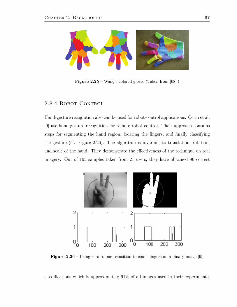
Chapter 2. Background 67
Figure 2.25 – Wang’s colored glove. (Taken from [68].)
2.8.4 Robot Control
Hand-gesture recognition also can be used for robot-control applications. Cetin et al.
[9] use hand-gesture recognition for remote robot control. Their approach contains
steps for segmenting the hand region, locating the fingers, and finally classifying
the gesture (cf. Figure 2.26). The algorithm is invariant to translation, rotation,
and scale of the hand. They demonstrate the effectiveness of the technique on real
imagery. Out of 105 samples taken from 21 users, they have obtained 96 correct
Figure 2.26 – Using zero to one transition to count fingers on a binary image [9].
classifications which is approximately 91% of all images used in their experiments.

Chapter 2. Background 68
Images taken under insufficient light (especially using the webcam) have led to the
incorrect results. In these cases the failure mainly stems from the erroneous segmen-
tation of some background portions as the hand region.
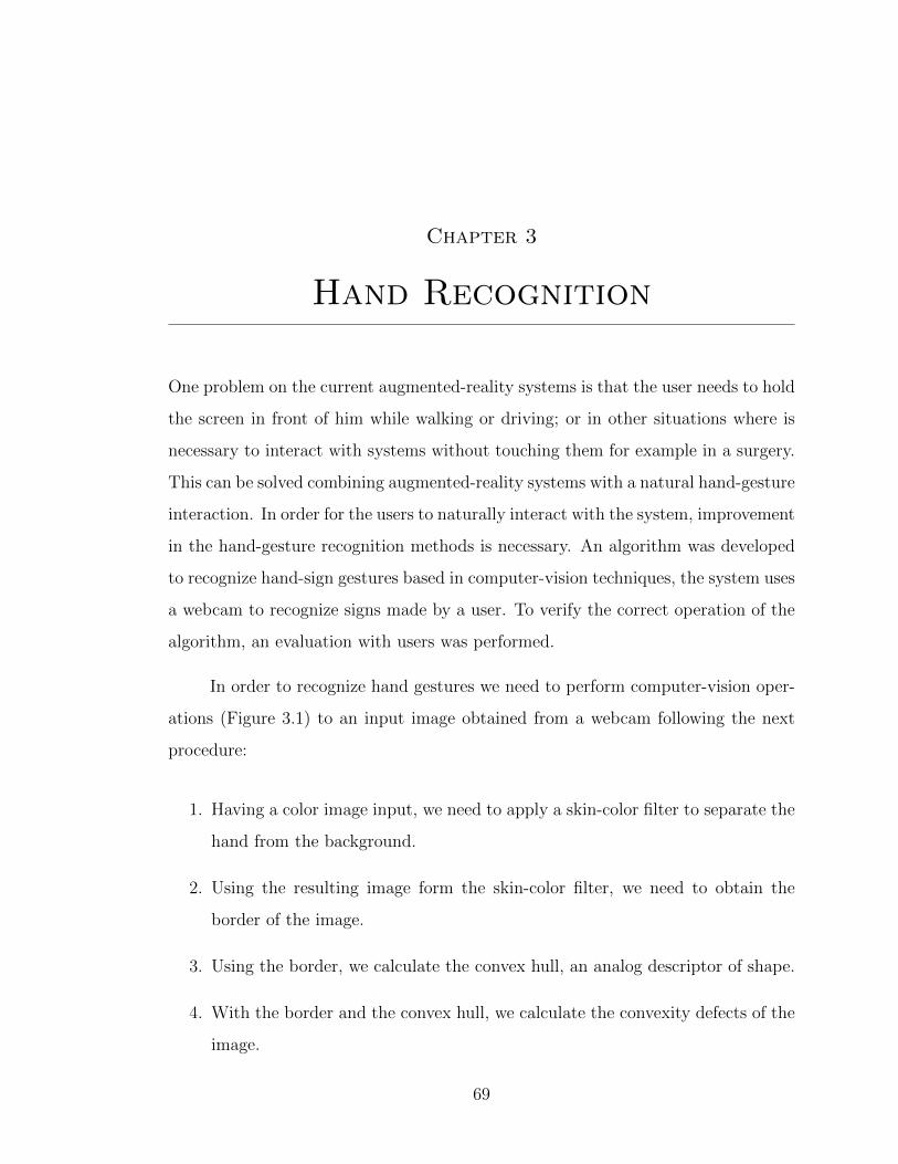
Chapter 3
Hand Recognition
One problem on the current augmented-reality systems is that the user needs to hold
the screen in front of him while walking or driving; or in other situations where is
necessary to interact with systems without touching them for example in a surgery.
This can be solved combining augmented-reality systems with a natural hand-gesture
interaction. In order for the users to naturally interact with the system, improvement
in the hand-gesture recognition methods is necessary. An algorithm was developed
to recognize hand-sign gestures based in computer-vision techniques, the system uses
a webcam to recognize signs made by a user. To verify the correct operation of the
algorithm, an evaluation with users was performed.
In order to recognize hand gestures we need to perform computer-vision oper-
ations (Figure 3.1) to an input image obtained from a webcam following the next
procedure:
1. Having a color image input, we need to apply a skin-color filter to separate the
hand from the background.
2. Using the resulting image form the skin-color filter, we need to obtain the
border of the image.
3. Using the border, we calculate the convex hull, an analog descriptor of shape.
4. With the border and the convex hull, we calculate the convexity defects of the
image.
69

Chapter 3. Hand Recognition 70
5. Having the convexity defects, we can detect useful characteristics of the hand
shape.
Figure 3.1 – The proposed hand-recognition procedure.
3.1 Skin-Color Filtering
Skin-color has proven to be an useful and robust cue for face detection, localization,
and tracking. Image-content filtering, content-aware video compression, and image
color-balancing applications can also benefit from automatic detection of skin in
images. The final goal of is to build a decision rule that will discriminate between
skin and non-skin pixels. This is usually accomplished by introducing a metric,
which measures distance (in general sense) of the pixel color to skin tone. The type
of this metric is defined by the skin-color modelling method.
Colorimetry, computer graphics, and video-signal transmission standards have
given birth to many color spaces with different properties. A wide variety of them
have been applied to the problem of skin-color modelling.

Chapter 3. Hand Recognition 71
3.1.1 Skin-Color Filter RGB
RGB is a color space originated from CRT (or similar) display applications, when it
was convenient to describe color as a combination of three colored rays (red, green,
and blue). It is one of the most widely used color spaces for processing and storing
digital image data.
Let I be the input image, where IR, IG and IB are the image red, green, and
blue channels:
{IR, IG, IB} ∈ Ni×j (3.1)
IR, IG, IB = [iRi,j], (3.2)
iRi,j∈ NR ⊆ N, (3.3)
NR = {0, 1, 2, ..., 255}, (3.4)
where i and j are the image width and height. We use a pixel-based skin detection
method [33] that classify each pixel as skin or non-skin individually, independently
from its neighbors. A pixel in I is classified as skin if it satisfies the following
conditions:
IR(x, y) > 95 (3.5)
IG(x, y) > 40 (3.6)
IB(x, y) > 20 (3.7)
max{IR(x, y), IG(x, y), IB(x, y)} −min{IR(x, y), IG(x, y), IB(x, y)} > 15 (3.8)
|IR(x, y)− IG(x, y)| > 15 (3.9)
IR(x, y) > IG(x, y) (3.10)
IR(x, y) > IB(x, y) (3.11)
We create a new binary image B (Figure 3.2) where:
B(x, y) =
{1, if is skin color classified,
0, otherwise.(3.12)

Chapter 3. Hand Recognition 72
3.1.2 Skin-Color Filter YCbCr
A pixel in I is classified as skin if it satisfies the following conditions:
IY c(x, y) > 80. (3.13)
85 > ICb(x, y) < 135. (3.14)
135 > ICr(x, y) < 180. (3.15)
In contrast to RGB, the YCbCr color space is luma-independent, resulting in
a better performance.
We create a new binary image B (Figure 3.2) where:
B(x, y) =
{1, if is skin color classified,
0, otherwise.(3.16)
The obvious advantage of this method is simplicity of skin-detection rules that
leads to construction of a very rapid classifier [64].
Figure 3.2 – Skin-color filter result. On the left the original image, on the right the
binary image with skin-color pixels show in white
3.2 Edge Detection
Edge detection is an essential tool in image processing and computer vision, particu-
larly in the areas of feature detection and feature extraction, which aim at identifying

Chapter 3. Hand Recognition 73
points in a digital image at which the image brightness has discontinuities. An edge
is the boundary between an object and the background, and indicates the boundary
between overlapping objects. This means that if the edges in an image can be iden-
tified accurately, all of the objects can be located and basic properties such as area,
perimeter, and shape can be measured [45].
There are two main methods of edge detection: Template Matching (TM) and
Differential Gradient (DG). In either case, the aim is to find where the intensity
gradient magnitude g is sufficiently large to be a reliable indicator of the edge in the
object. The TM and DG methods differ mainly in how they estimate g locally. Both
DG and TM operators estimate local intensity gradients with the aid of suitable
convolution masks (cf. Figure 3.17).
The idea behind template-based edge detection is to use a small discrete tem-
plate as a model of an edge instead of using a derivative operator directly. Example
masks for the Sobel 3 × 3 operator are the following:
Sx =
−1 0 1
−2 0 2
−1 0 1
, Sy =
1 2 1
0 0 0
−1 −2 −1
.
One way to view these templates is an approximation to the gradient at the pixel
corresponding to the center of the template. The horizontal component of the Sobel
operator is Sx and the vertical component is Sy.
In the differential gradient approach, the local edge magnitude of the pixel may
be computed vectorially using the non-linear transformation:
g =√g2x + g2y. (3.17)
For a pixel in the binary image B with coordinates (i, j), Sx and Sy can be
computed by:
Sx = B[i−1][j+1] + 2B[i][j+1] + B[i+1][j+1]
−(B[i−1][j−1] + 2B[i][j−1] + B[i+1][j−1]),(3.18)

Chapter 3. Hand Recognition 74
Sy = B[i+1][j+1] + 2B[i+1][j] + B[i+1][j−1]
−(B[i−1][j+1] + +2B[i−1][j] + B[i−1][j−1]).(3.19)
After Sx and Sy are computed for every pixel in an image, the resulting magnitudes
must be thresholded. All pixels will have some response to the templates, but only
the very large responses will correspond to edges. As a result we have a sequence
C ∈ Rn of the contour points.
3.3 Convex Hull
The convex hull is an analog descriptor of shape, being defined (in two dimensions)
as the shape unclosed by an elastic band placed around the object in question (Figure
3.5). It may be used to simplify complex shapes to provide a rapid indication of the
extent of an object.
A simple means of obtaining the convex hull is to repeatedly fill in the center
pixel of all neighborhoods that exhibit a concavity until no further change occurs.
The algorithm is shown in the Figure 3.4.
0 1 1
1 0 0
0 0 0
Figure 3.3 – Example of a pixel neighborhood.
In the example (Figure 3.3), a corner pixel in the neighborhood is 0 and is
adjacent to two 1’s; it makes no difference to the 8-connectedness condition whether
the corner is 0 or 1. We then get a simple rule for determining whether to fill in the
center pixel. If there are four or more 1’s around the boundary of the neighborhood,
then there is a concavity that must be filled in.
The result is a sequence H ∈ Rn of the convex hull points.

Chapter 3. Hand Recognition 75
Figure 3.4 – Convex hull algorithm [13].
1 do {
2 finished = true;
3 sigma = A1+A2+A3+A4+A5+A6+A7+A8
4 + A1 && !A2 && A3) + (A3 && !A4 && A5)
5 + A5 && !A6 && A7) + (A7 && !A8 && A1);
6 if ( (A0 = 00) && (sigma > 3) ) {
7 B0 = 1;
8 finished = false;
9 }
10 else B0 = A0;
11 [A0 = B0]
12 } until finished;
Figure 3.5 – Border (blue) and convex hull (green).
3.4 Convexity Defects
In addition, from the hand’s contour and the hand’s convex hull it is possible to
calculate a sequence of contour points between two consecutive convex-hull vertices.
This sequence forms the so-called and it is possible to compute the depth of the

Chapter 3. Hand Recognition 76
ith-convexity defect, di (Figure 3.6). From these depths some useful characteristics
for the hand shape can be derived like the depth average:
d =1
n
∑i=0..n
di, (3.20)
where n is the total number of convexity defects in the hand’s contour.
The first step of the gesture-recognition process is to model the “start” gesture.
The average of the depths of the convexity defects of an opened hand with separated
fingers is larger than in an open hand with no separated fingers or in a fist.
Figure 3.6 – Convexity defects (yellow), convex hull (green), and defect start-end
points (red).

Chapter 4
Prototype
To test the algorithm proposed in this thesis, we created a prototype of a hand-
gesture detection system, in both software and hardware. We wanted to this system
to be simple, it is easy to use and to extend for use in multiple applications as we
made use of open-source libraries. We wanted the system to be able to run in modest
hardware, so it can be used in a mobile application.
4.1 Hardware
As the system was intended for a mobile application, we search hardware require-
ments (processing speed, memory, resolution) that can be easily satisfied by today
mobile devices (Table 4.1). The algorithm was implemented in a computer with 1.6
GHz processor and 1 GB of RAM memory using a webcam. In our case we use a Log-
itech1 QuickCam Zoom V-UW21, with 640 × 480 pixels of resolution (aproximately
0.3 MP).
Table 4.1 – Comparison of mobile devices.
Model CPU RAM CAMERA
Samsung Galaxy S42 1.9 GHz quad-core 2 GB 13 MP rear, 2 MP front
ZTE Grand S3 1.7 GHz quad-core 2 GB 13 MP rear, 2 MP front
1 http://www.logitech.com2 http://www.samsung.com/3 http://wwwen.zte.com.cn/en/
77

Chapter 4. Prototype 78
Sony Xperia Z4 1.5 GHz quad-core 2 GB 13.1 MP rear, 2.2 MP front
BlackBerry Z105 1.5 GHz dual-core 2 GB 8 MP rear, 2 MP front
Apple iPhone 56 1.3 GHz dual-core 1 GB 8 MP rear, 1.2 MP front
4.2 Software
We use OpenCV7 (Open Source Computer Vision) a library of common programming
functions for real-time computer vision, and the Python8 programing language for
the implementation of the hand-recognition system.
The algorithm has a good performance and is capable of estimate in real time
the number of fingers in a sign made with the hand (Figure 4.1). The procedure for
the hand-recognition is as follows:
1. Get an image from the camera: The system is capable to function with a
common standard webcam, in our case we use a Logitech9 QuickCam Zoom
V-UW21.
2. Resize the image: Regardless the size of the input image, we reduce this image
to 160 × 120 pixels (aproximately 0.02 MP)for a faster processing. In this step
we use the OpenCV function resize().
3. Apply the skin-color filter: The input image is split in three different compo-
nents using the OpenCV function split(), after that the skin-color filter rules??
are applied in order to create a new binary image.
4 http://www.sonymobile.com/global-en/products/phones/xperia-z/5 http://us.blackberry.com/smartphones/blackberry-z10.html6 http://www.apple.com/iphone/7 http://opencv.willowgarage.com/8 http://www.python.org/9 http://www.logitech.com
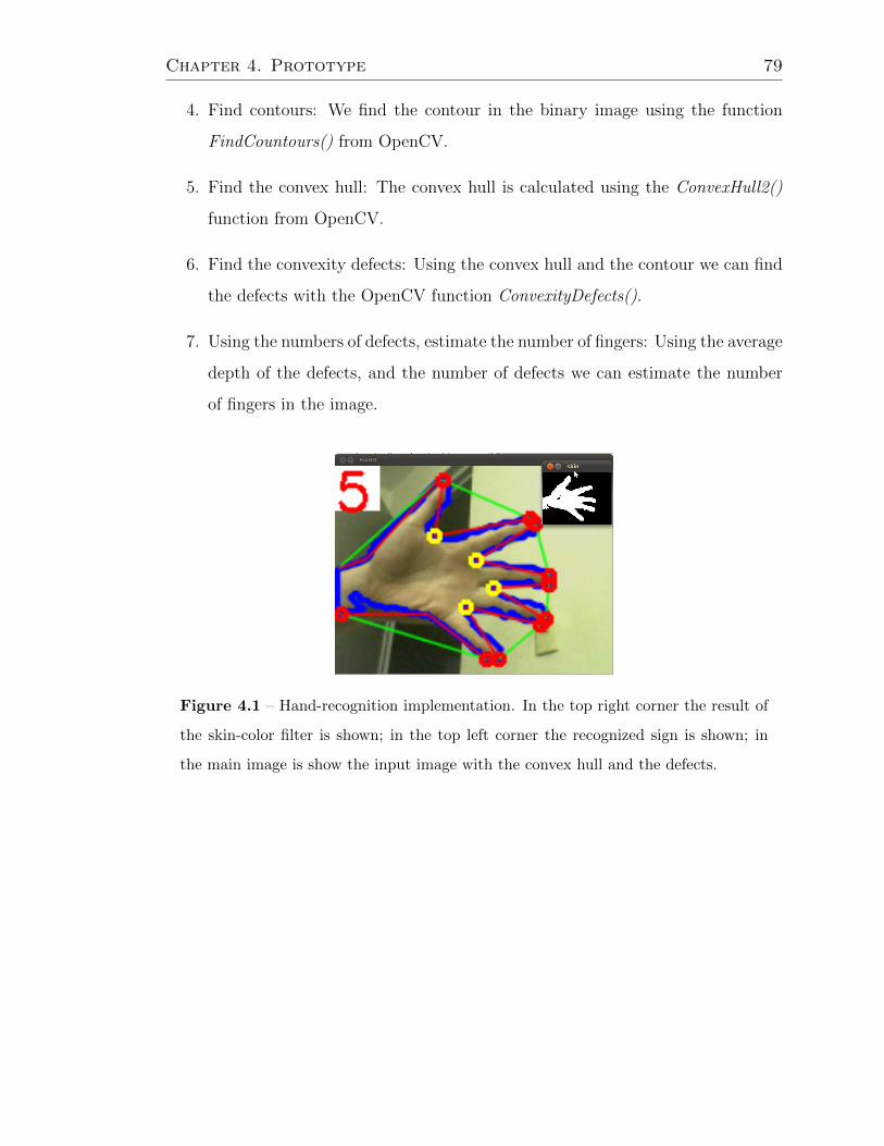
Chapter 4. Prototype 79
4. Find contours: We find the contour in the binary image using the function
FindCountours() from OpenCV.
5. Find the convex hull: The convex hull is calculated using the ConvexHull2()
function from OpenCV.
6. Find the convexity defects: Using the convex hull and the contour we can find
the defects with the OpenCV function ConvexityDefects().
7. Using the numbers of defects, estimate the number of fingers: Using the average
depth of the defects, and the number of defects we can estimate the number
of fingers in the image.
Figure 4.1 – Hand-recognition implementation. In the top right corner the result of
the skin-color filter is shown; in the top left corner the recognized sign is shown; in
the main image is show the input image with the convex hull and the defects.

Chapter 5
Experiments
In this chapter we present the different experiments that we use to evaluate the
performance of the algorithm, user experiments and computational experiments.
The user experiments were performed with real users in real time, we measure the
signs detected correctly. For the computational experiment we use still frames of the
signs, and we evaluate the performance when noise is introduced to the image. We
also attempt to improve the algorithm using other measures as the hand-to-finger
ratio.
5.1 User Experiments
The purpose of the experiments is to verify the correct operation of the first stage
of the gesture-recognition algorithm. To do this verification, we performed an eval-
uation with users; the users perform a series of gestures that were to be correctly
identified by the algorithm.
5.1.1 Setup
The users make the gestures in front of a webcam, and an observer records if the
output produced by the algorithm matches with the actual gesture being made.
Because variations in lighting, camera position, and background can affect the per-
formance of the algorithm, these are controlled. Consequently, an arrangement with
80

Chapter 5. Experiments 81
a fixed background, a still camera, and a source of constant illumination was created
(Figure 5.1).
Figure 5.1 – Background, camera, and illumination arrangement.
After being instructed about the experiment, each user sits in front of the
camera and place his or her right hand on the background to start making sequences
of signs. Each sequence consist of a permutation of six different signs (numbers from
zero to five) which was randomly generated. Figure 5.2 shows one of the sequences
used.
Leaving a gap of three seconds between signs, the user performs (one sign at
a time) a sequence displayed on the screen. After performing the sequence with the
right hand, the user switches hands and repeats the same sequence of signs with his
or her left hand now. This procedure is repeated for five different sequences.
Figure 5.2 – Example of a random sign sequence.
An observer records results using a format (cf. Figure 5.3), where he marks
whether the algorithm was or was not able to recognize each sign made by the user.

Chapter 5. Experiments 82
Figure 5.3 – Format used by the observer (the original was in Spanish, native language
of the users).
Figure 5.4 – Experimental setup.
5.1.2 First Set of Experiments
To perform the evaluation, we placed the background with the camera and the illu-
mination next to a computer that showed the sequences and ran the sign recognition
algorithm (Figure 5.4). We evaluated with seven users; each one performed five se-
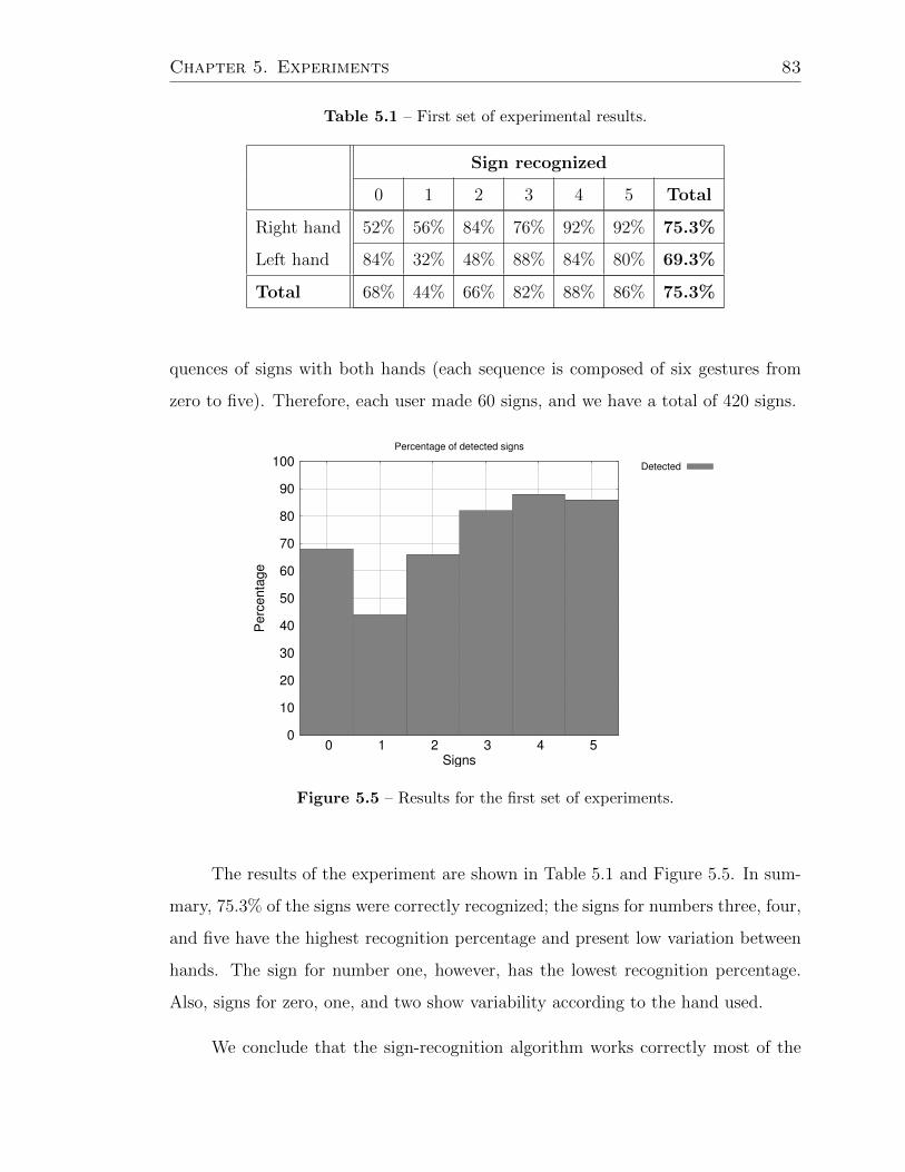
Chapter 5. Experiments 83
Table 5.1 – First set of experimental results.
Sign recognized
0 1 2 3 4 5 Total
Right hand 52% 56% 84% 76% 92% 92% 75.3%
Left hand 84% 32% 48% 88% 84% 80% 69.3%
Total 68% 44% 66% 82% 88% 86% 75.3%
quences of signs with both hands (each sequence is composed of six gestures from
zero to five). Therefore, each user made 60 signs, and we have a total of 420 signs.
0
10
20
30
40
50
60
70
80
90
100
0 1 2 3 4 5
Perc
enta
ge
Signs
Percentage of detected signs
Detected
Figure 5.5 – Results for the first set of experiments.
The results of the experiment are shown in Table 5.1 and Figure 5.5. In sum-
mary, 75.3% of the signs were correctly recognized; the signs for numbers three, four,
and five have the highest recognition percentage and present low variation between
hands. The sign for number one, however, has the lowest recognition percentage.
Also, signs for zero, one, and two show variability according to the hand used.
We conclude that the sign-recognition algorithm works correctly most of the

Chapter 5. Experiments 84
Table 5.2 – Percentage of correctly identified gestures.
Hand usedGesture recognized
0 1 2 3 4 5 Total
Right hand 100% 72% 96% 94% 98% 100% 93.33%
Left hand 100% 76% 94% 96% 98% 94% 93.00%
Total 100% 74% 95% 95% 98% 97% 93.17%
time considering the conditions used in the experiments: fixed background and illu-
mination, different users, and different hands. The primary cause for incorrect sign
recognition was the particular form in which each user performs the sign; although
this was partially controlled by displaying the signs to be made, these vary slightly
from one user to another in a natural way (Figure 5.7). Sometimes, for example, the
fingers were very close to each other, difficulting the calculation of the convex-hull
defects or causing the recognition of a wrong number. In other cases, a slight twist
of the wrist causes the same problems.
5.1.3 Second Set of Experiments
We evaluated the prototype with ten users; each performed five sequences of gestures
with both hands (each sequence was composed of six gestures from zero to five, in
random order). Therefore, each user performed 60 gestures, giving us a total of
600 gesture-recognition attempts. Table 5.2 shows the percent of gestures correctly
recognized, grouped by the gesture made and the hand used.
In total, 93.1% of the gestures were correctly recognized, improving the results
for a previous work [46]; the gestures for numbers three, four, and five have the
highest accuracy and present low variation between hands. The gestures for number
one, however, has the lowest recognition percentage. Also, gestures for zero, one,
and two show variability according to the hand used. The gesture-recognition al-
gorithm works correctly a majority of the time, under the conditions used in our

Chapter 5. Experiments 85
Figure 5.6 – Correctly recognized gestures.
experiments. User observation helped us notice that the primary cause for incorrect
gesture recognition was the particular form in which each user performs the gesture:
sometimes, for example, the fingers were very close to each other. Some examples
are shown in Figure 5.7.
5.2 Computational Experiments
We use 30 different still images from each sign to perform an evaluation of the
algorithm when noise is added to the image. We also seek to improve the sign
detection using the area of the fingers to differentiate between signs. We test only
the signs one, two, three, and four, being these the more difficult to differentiate
between them. The images were taken in a light background using a standard
webcam with a resolution of 1024 × 768 pixels which later was resized to 640 × 480
pixels.

Chapter 5. Experiments 86
(a) Correct recognition of the
number five sign.
(b) Incorrect recognition of the
number five sign.
(c) Correct three sign recognition. (d) Incorrect three sign recogni-
tion.
(e) Correct one sign recognition (f) Incorrect one sign recognition.
Figure 5.7 – Incorrect sign recognition.
5.2.1 Noise
We introduce random noise (Figure 5.8) to the original image with different levels
in order to evaluate the performance of the algorithm. For generating the random

Chapter 5. Experiments 87
noise we use the OpenCV function RandArr that fills an array with random numbers
in our case numbers between zero and 255 for each pixel, then the generated array is
added to the original image using a weighted add using values from 10% to 50% with
increments of 5%. Let I be the input image and N the noise generated, the new image
I ′ is the weighted add using the parameter p ∈ {0.1, 0.15, 0.2, 0.3, 0.35, 0.4, 0.45, 0.5}.
I ′ = (1− p)× I + p×N. (5.1)
In Figure 5.9 is shown that low levels of noise results in a higher number of
signs detected correctly, and as the noise is increased the signs detected correctly
decreases being the signs of the numbers two and three the more “noise-resistant”.
5.2.2 Area
One problem to correctly detect a sign was when the fingers were to close to each
other. To deal with this problem we propose the use of the finger/hand area ratio.
We calculate the ratio between the area of the fingers and the area of the hand.
Thus to help differentiate the signs using the area. A number four sign would have
a bigger area than a number three sign and so on. The first steps of the algorithm
are the same (Figure 3.1), after the convexity defects are found the image is rotated
to put the hand in a vertical position, as the middle finger length is approximately
50% of the hand length [22, 63], we cut the image by the half and calculate the area
of the upper half, this being the area of the fingers.
In Figure 5.11 we see the difference between the signs, using the areas is easy
to differentiate between the signs one and four, the number two and three being
more difficult showing a wider range of values in the experiments.
5.2.3 Processing Time
We measure te processing time required to detect the sign, from the moment when
the input image is captured to the time when the result is displayed. We obtain a

Chapter 5. Experiments 88
(a) Original (b) 10% (c) 15%
(d) 20% (e) 25% (f) 30%
(g) 35% (h) 40% (i) 45%
(j) 50%
Figure 5.8 – Random noise added to the images for testing.
mean of 270.1 milliseconds over 100 trials (Fig. 5.12). Although is a high processing
time, it was proved to be adeccuate for the applications we proposed in section 6.

Chapter 5. Experiments 89
0.10
0.15
0.20
0.25
0.30
0.35
0.40
0.45
0.50
1 2 3 4
nois
e
sign
ACCURACY
0
10
20
30
40
50
60
70
80
90
100
Figure 5.9 – Accuracy with different noise levels.
Figure 5.10 – Area used (color blue) to calculate the hand/finger area ratio. The
green square is the minimum rectangle enclosing the hand, used for rotate the image.
The white rectangle is the top half of the image used to find the finger area.
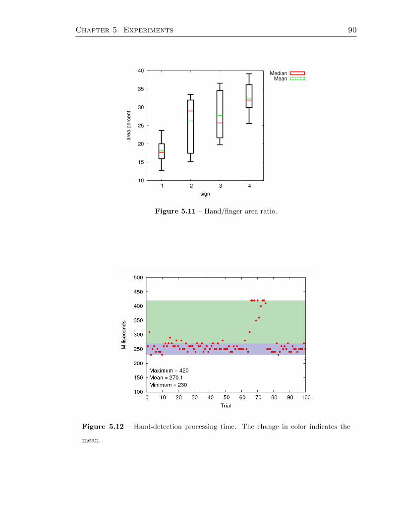
Chapter 5. Experiments 90
10
15
20
25
30
35
40
1 2 3 4
are
a p
erc
ent
sign
MedianMean
Figure 5.11 – Hand/finger area ratio.
Figure 5.12 – Hand-detection processing time. The change in color indicates the
mean.
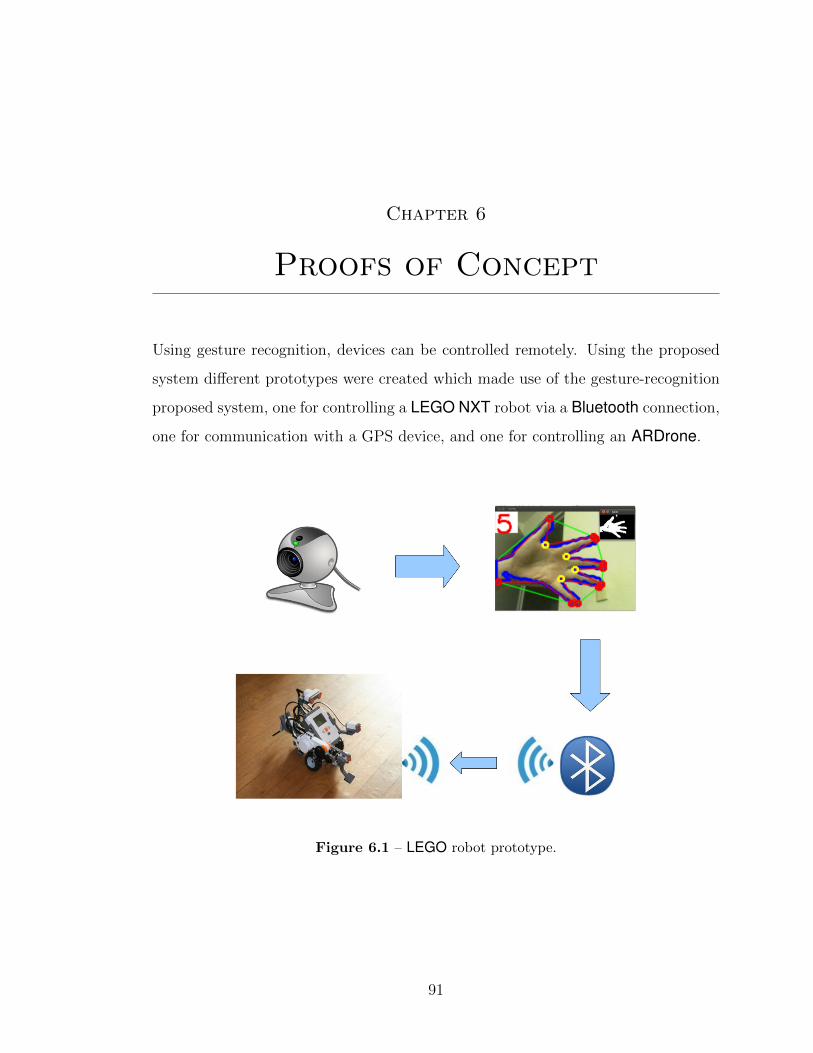
Chapter 6
Proofs of Concept
Using gesture recognition, devices can be controlled remotely. Using the proposed
system different prototypes were created which made use of the gesture-recognition
proposed system, one for controlling a LEGO NXT robot via a Bluetooth connection,
one for communication with a GPS device, and one for controlling an ARDrone.
Figure 6.1 – LEGO robot prototype.
91

Chapter 6. Proofs of Concept 92
6.1 LEGO Robot
For communication with the LEGO1 robot NXT Python2 libraries are used to create
a connection using the Bluetooth address of the LEGO brick. If the device is found
a channel of communication is created and the connection is activated. The action
the robot takes is determined according to the recognized signal, andthe instructions
are sent via a Bluetooth connection.
The functions of the movements are performed according to the physical con-
figuration of the LEGO robot. In this case the robot has two wheel motors connected
to ports B and C plus an additional motor port A if required by the robot configured
to perform a specific action. If one wants the motor forward, both motors must be
activated, if one wants the robot back off the two motors must be activated in the
opposite direction. To turn left or right must be activated a motor forward and one
in reverse.
6.2 GPS Device
For communication with the GPS device, we made use of a microcontroller Ar-
duinoUNO3, to which was added a GPS module, a digital compass, and an ac-
celerometer (cf. Figure 6.3). Using the signal detected by the gesture-recognition
system commands are sent via USB device to interact with the commands shown in
Table 3. Depending on the user signal, data is obtained either from the accelerom-
eter, compass, or GPS. When GPS data is obtained, the position is displayed in a
browser window using Google Maps.
1 http://mindstorms.lego.com/en-us/Default.aspx2 http://home.comcast.net/~dplau/nxt_python/3 http://www.arduino.cc/en/Main/arduinoBoardUno

Chapter 6. Proofs of Concept 93
Figure 6.2 – Example of turn-left function for the LEGO robot.
1 left():
2 motor_left = Motor(brick, PORT_B)
3 motor_left.power = 50
4 motor_left..mode = MODE_MOTOR_ON
5 motor_left.run._state = RUN_STATE_RUNNING
6 motor_left.tacho_limit = 90
7 motor_left.set_output_state()
8 motor_right=Motor(brick, PORT_C)
9 motor_right.power = -50
10 motor_right.mode = MODE_MOTOR_ON
11 motor_right.run._state = RUN_STATE_RUNNING
12 motor_right.tacho_limit = 90
13 motor_right.set_output_state()
Figure 6.3 – GPS-system prototype.

Chapter 6. Proofs of Concept 94
6.3 AR.DRONE
In the AR.Drone4 application, the user wears an augmented-reality head set, the
camera on the head set captures the hand movements; the signs are recognized
by the hand-recognition system and send to the drone via wireless connection (cf.
Figure 6.4).
Figure 6.4 – AR.Drone-system prototype.
4 http://ardrone.parrot.com/parrot-ar-drone/usa/

Chapter 7
Conclusions and Future Work
We presented a new method for recognizing hand gestures based on computer-vision
techniques, together with an implementation that works on a ordinary webcam. The
method combines skin-color filtering, border detection, convex-hull computation, and
a rule-based reasoning with the depths of the convexity defects. We report users
experiments on the recognition accuracy of the developed prototype, recognizing
correctly three in four hand signs made on either hand, in a controlled environment.
We add in the sign-recognition phase an estimate of the area of each finger. This
allows us to determine whether a single finger is elevated at that position or whether
multiple fingers are elevated but held together.
The finger width can be calibrated for each person by measuring the width of
the hand base itself and assuming that anything that has the width between one
sixth and one fourth of the base width is a single finger. The number of fingers in a
wider block can be estimated as the width of the block (computable from the points
used for finger counting at present) divided by one fifth of the base width, rounded
down to the preceding integer value.
Another aspect that needs to be addressed in future work is the sensibility of
the system to lighting conditions, as this affects the skin-color filtering, particularly
with reflections and shadows. We expect these additions to improve the accuracy
of the recognition system, as well as ease the cognitive burden of the end user as it
will no longer be necessary to keep the fingers separate, something that one easily
forgets.
95

Chapter 7. Conclusions and Future Work 96
Part of this thesis work was presented with the title “A Tool for Hand-Sign
Recognition” [46] on the Mexican Congress on Pattern Recognition (MCPR 2012)
held in Huatulco, Mexico. Proceedings of the conference was published in the Lecture
Notes in Computer Science series by Springer.

Bibliography
[1] F. Ahmad and P. Musilek. A keystroke and pointer control input interface for
wearable computers. In IEEE International Conference on Pervasive Comput-
ing and Communications, pages 2–11, Los Alamitos, CA, USA, 2006. IEEE
Computer Society.
[2] F. Ahmad and P. Musilek. Ubihand: a wearable input device for 3D interaction.
In ACM Internacional Conference and Exhibition on Computer Graphics and
Interactive Techniques, page 159, New York, NY, USA, 2006. ACM.
[3] A. Argyros and M. Lourakis. Vision-based interpretation of hand gestures for
remote control of a computer mouse. In T. Huang, N. Sebe, M. Lew, V. Pavlovic,
M. Kolsch, A. Galata, and B. Kisacanin, editors, Computer Vision in Human-
Computer Interaction, volume 3979 of Lecture Notes in Computer Science, pages
40–51. Springer, Berlin / Heidelberg, Germany, 2006.
[4] R. T. Azuma. A survey of augmented reality. Presence, 6:355–385, 1997.
[5] G. Bieber. Non-deterministic location model on PDAs for fairs, exhibitions and
congresses. Workshop at Ubicomp 2001, Sept. 2001.
[6] N. Bourdeau, J. Riba, F. Sansone, M. Gibeaux, M. Gibeaux, B. T. Europa,
and F. S. Ertico. Hybridised GPS and GSM positioning technology for high
performance. In Proceedings of IST Mobile and Wireless Telecommunications,
2002.
[7] M. Bray, E. Koller-meier, and L. V. Gool. Smart particle filtering for 3D hand
97

Chapter 7. Bibliography 98
tracking. In Proceedings of Sixth IEEE International Conference on Automatic
Face and Gesture Recognition, pages 675–680. IEEE, 2004.
[8] S. Carter, C. Liao, L. Denoue, G. Golovchinsky, and Q. Liu. Linking digital me-
dia to physical documents: Comparing content- and marker-based tags. IEEE
Pervasive Computing, 9(2):46–55, apr 2010.
[9] M. Cetin, A. K. Malima, and E. Ozgur. A fast algorithm for vision-based hand
gesture recognition for robot control. In Proceedings of the IEEE Conference
on Signal Processing and Communications Applications, pages 1–4, NJ, USA,
2006. IEEE.
[10] W. Chan. Dealfinder: A collaborative, location-aware mobile shopping ap-
plication. Short paper submitted to the Computer Human Interaction 2001
conference, 2001.
[11] A. Cooper, R. Reimann, and D. Cronin. About Face 3: The Essentials of
Interaction Desing. Wiley Publishing, Inc., 2007.
[12] S. C. Crampton and M. Betke. Counting fingers in real time: A webcam-based
human-computer interface game applications. In Proceedings of the Conference
on Universal Access in Human-Computer Interaction, pages 1357–1361, Crete,
Greece, June 2003. HCI International.
[13] E. R. Davies. Machine Vision: Theory, Algorithms, Practicalities. Morgan
Kaufmann Publishers Inc., San Francisco, CA, USA, 2004.
[14] A. de Fatima dos Santos, C. de Souza, N. Rivers de Queiroz, G. Cancela e.
Penna, E. M. Neves de. Pinho e. Medeiros, and H. J. Alves. Incorporation
of telehealth resources in belo horizonte’s SAMU: Qualifying and improving
care. In ETELEMED ’09: Proceedings of the 2009 International Conference
on eHealth, Telemedicine, and Social Medicine, pages 72–76, Washington, DC,
USA, 2009. IEEE Computer Society.

Chapter 7. Bibliography 99
[15] G. Deepak and B. S. Pradeep. Challenging issues and limitations of mobile
computing. Computing, 3(1):177–181, 2012.
[16] G. Dewaele, F. Devernay, and R. Horaud. Hand motion from 3d point trajecto-
ries and a smooth surface model. In 8th European Conference on Computer Vi-
sion., volume 1 of Lecture Notes on Computer Science, pages 495–507. Springer,
Berlin / Heidelberg, 2004.
[17] R. Djuknic, G.M. Richton. Geolocation and assisted GPS. Computer, Feb.
2001.
[18] M. R. Ebling and R. Caceres. Gaming and augmented reality come to location-
based services. IEEE Pervasive Computing, 9:5–6, 2010.
[19] A. Erol, G. Bebis, M. Nicolescu, R. D. Boyle, and X. Twombly. Vision-based
hand pose estimation: A review. Computer Vision and Image Understanding,
108:52–73, 2007.
[20] B. Ferris, K. Watkins, and A. Borning. Location-aware tools for improving
public transit usability. IEEE Pervasive Computing, 9:13–19, 2009.
[21] G. H. Forman and J. Zahorjan. The challenges of mobile computing. IEEE
Computer, 27:38–47, 1994.
[22] A. Freivalds. Biomechanics of the Upper Limbs: Mechanics, Modeling, and
Musculoskeletal Injuries. London: CRC Press, Boca Raton, 2004.
[23] P. Frohlich, R. Simon, and C. Kaufmann. Adding space to location in mobile
emergency response technologies. In J. Loffler and M. Klann, editors, Mobile
Response, volume 4458 of Lecture Notes in Computer Science, pages 71–76.
Springer, Berlin / Heidelberg, 2007.
[24] V. K. Garg. Elements of distributed computing. John Wiley & Sons, Inc., New
York, NY, USA, 2002.

Chapter 7. Bibliography 100
[25] K. Gaßner, G. Vollmer, M. Prehn, M. Fiedler, and S. Ssmoller. Smart food:
Mobile guidance for food-allergic people. In Seventh IEEE International Con-
ference on E-Commerce Technology, 2005., pages 531–534. IEEE Computer
Society, 2005.
[26] E. B. Goldstein. Sensacion y percepcion. International Thompson Editores,
Mexico, 2007.
[27] D. Hebb. The Organization of Behavior. Wiley, New York, 1949.
[28] K. P. Hewagamage and M. Hirakawa. Situated computing: A paradigm to
enhance the mobile user’s interaction. Handbook of Software Engineering and
Knowledge Engineering, pages 200–223, 2000.
[29] Y. Hirobe, T. Niikura, Y. Watanabe, T. Komuro, and M. Ishikawa. Vision-
based input interface for mobile devices with high-speed fingertip tracking. In
22nd ACM Symposium on User Interface Software and Technology, pages 7–8,
New York, NY, USA, 2009. ACM.
[30] J. Johnson. Designing with the mind in mind. Morgan Kaufmann Publishers,
2010.
[31] M. Kolsch. Vision Based Hand Gesture Interfaces for Wearable Computing and
Virtual Environments. PhD thesis, University of California, Santa Barbara,
CA, USA, 2004.
[32] P. Kourouthanassis, D. Spinellis, G. Roussos, and G. M. Giaglis. Intelligent
cokes and diapers: Mygrocer ubiquitous computing environment. In Proceedings
of The First International Conference on Mobile Business, Athens, Greece,
2002.
[33] J. Kovac, P. Peer, and F. Solina. Human skin colour clustering for face detection.
In Internacional conference on Computer as a Tool, volume 2, pages 144–147,
NJ, USA, 2003. IEEE.

Chapter 7. Bibliography 101
[34] J. Krumm. Ubiquitous advertising: The killer application for the 21st century.
IEEE Pervasive Computing, 99:66–73, 2010.
[35] N. Lavi, I. Cidon, and I. Keidar. Magma: mobility and group management
architecture for real-time collaborative applications. Wireless Communications
and Mobile Computing, 5:749–772, 2005.
[36] J. C. Lee. In search of a natural gesture. XRDS, 16(4):9–12, June 2010. ISSN
1528-4972.
[37] S. Lenman, L. Bretzner, and B. Thuresson. Computer vision based hand gesture
interfaces for human-computer interaction. Technical report, CID, Centre for
User Oriented IT Design. Royal Institute of Technology Sweden, Stockhom,
Sweden, June 2002.
[38] J. Lin, Y. Wu, and T. S. Huang. Capturing human hand motion in image
sequences. In Proceeding of Workshop on Motion and Video Computing, pages
99–104, Washington, DC, USA, 2002. IEEE Computer Society.
[39] S. Lu, D. Metaxas, and D. Samaras. Using multiple cues for hand tracking and
model refinement. In Proceedings of International Conference on Computer
Vision and Pattern Recognition, pages 443–450. IEEE Computer Society, 2003.
[40] J. MacLean, R. Herpers, C. Pantofaru, L. Wood, K. Derpanis, D. Topalovic,
and J. Tsotsos. Fast hand gesture recognition for real-time teleconferencing ap-
plications. In Proceedings of the IEEE ICCV Workshop on Recognition, Analy-
sis, and Tracking of Faces and Gestures in Real-Time Systems, pages 133–140,
Washington, DC, USA, 2001. IEEE Computer Society.
[41] R. Messeguer, S. F. Ochoa, J. A. Pino, E. Medina, L. Navarro, D. Royo, and
A. Neyem. Building real-world ad-hoc networks to support mobile collaborative
applications: Lessons learned. volume 5784/2009 of Lecture Notes in Computer
Science, pages 1–16. Springer, Berlin / Heidelberg, July 2009.
Chapter 7. Bibliography 102
[42] P. Mistry, P. Maes, and L. Chang. WUW - wear ur world: a wearable gestural
interface. In Proceedings of the 27th international conference extended abstracts
on Human factors in computing systems, pages 4111–4116, New York, NY,
USA, 2009. ACM. ISBN 978-1-60558-247-4.
[43] J. O’Brien and M. Shapiro. An application framework for nomadic, collaborative
applications. In F. Eliassen and A. Montresor, editors, Distributed Applications
and Interoperable Systems, volume 4025 of Lecture Notes in Computer Science,
pages 48–63. Springer, Berlin / Heidelberg, 2006.
[44] S. F. Ochoa, R. Alarcon, and L. A. Guerrero. Understanding the relationship
between requirements and context elements in mobile collaboration. In J. A.
Jacko, editor, HCI (3), volume 5612 of Lecture Notes in Computer Science,
pages 67–76. Springer, Berlin / Heidelberg, 2009.
[45] J. R. Parker. Algorithms for Image Processing and Computer Vision. John
Wiley & Sons, Inc., New York, NY, USA, 1 edition, 1996.
[46] D. J. Rios Soria and S. E. Schaeffer. A tool for hand-sign recognition. In 4th
Mexican Conference on Pattern Recognition, volume 7329 of Lecture Notes in
Computer Science, pages 137–146. Springer, Berlin / Heidelberg, 2012.
[47] S. Roomi, R. Priya, and H. Jayalakshmi. Hand gesture recognition for human-
computer interaction. Journal of Computer Science, 6(9):1002–1007, 2010.
[48] J. Roth. Mobility support for replicated real-time applications. In Lecture Notes
in Computer Science 2346, pages 2002–181, Berlin / Heidelberg, 2002. Springer.
[49] J. Santa and A. F. Gomez-Skarmeta. Sharing context-aware road and safety
information. IEEE Pervasive Computing, 8:58–65, 2009.
[50] C. Sapateiro, P. Antunes, G. Zurita, R. Vogt, and N. Baloian. Evaluating a
mobile emergency response system. In R. Briggs, P. Antunes, G.-J. de Vreede,
and A. Read, editors, Groupware: Design, Implementation, and Use, volume
Chapter 7. Bibliography 103
5411 of Lecture Notes in Computer Science, pages 121–134. Springer, Berlin /
Heidelberg, 2008.
[51] J. Schirmer and H. Bach. Context management in an agent-based approach
for service assistance in the domain of consumer electronics. In Proceedings
Pervasive 02, Berlin / Heidelberg, Nov. 2000. Springer.
[52] T. Schlomer, B. Poppinga, N. Henze, and S. Boll. Gesture recognition with a
Wii controller. In Proceedings of the 2nd international conference on Tangible
and embedded interaction, pages 11–14, New York, NY, USA, 2008. ACM.
[53] R. Simon, H. Kunczier, and H. Anegg. Towards Orientation-Aware Location
Based Mobile Services. Lecture Notes in Geoinformation and Cartography.
Springer, Berlin/Heidelberg, 2007.
[54] A. Steed. Supporting mobile applications with real-time visualisation of gps
availability. In Proceedings of Mobile HCI 2004, volume 3160 of Lecture Notes
in Computer Science, pages 373–377. Springer, Berlin / Heidelberg, 2004.
[55] B. Stenger, A. Thayananthan, P. Torr, and R. Cipolla. Hand pose estima-
tion using hierarchical detection. In Proceedings of International Workshop on
Human-Computer Interaction, Lecture Notes in Computer Science, pages 102–
112, Berlin/Heidelberg, 2004. Springer.
[56] E. Stergiopoulou and N. Papamarkos. Hand gesture recognition using a neural
network shape fitting technique. Engineering Applications of Artificial Intelli-
gence, 22(8):1141–1158, 2009.
[57] D. J. Sturman and D. Zeltzer. A survey of glove-based input. IEEE Computer
Graphics Applications, 14:30–39, January 1994.
[58] K.-W. Su, S.-L. Hwang, and C.-T. Wu. Developing a usable mobile expert sup-
port system for emergency response center. In Proceedings of International Mul-
tiConference of Engineers and Computer Scientists, pages 13–17, Hong Kong,
China., 2006.

Chapter 7. Bibliography 104
[59] E. B. Sudderth, M. I. M, W. T. Freeman, and A. S. Willsky. Visual hand track-
ing using nonparametric belief propagation. In Propagation, IEEE Workshop
on Generative Model Based Vision, pages 189–198, 2004.
[60] K. Terajima, T. Komuro, and M. Ishikawa. Fast finger tracking system for in-air
typing interface. In Proceedings of the 27th international conference: extended
abstracts on Human factors in computing systems, pages 3739–3744, New York,
NY, USA, 2009. ACM.
[61] P. Thagard. Mind, Introduction to Cognitive Science. MIT Press, 2005.
[62] J. Usabiaga, A. Erol, G. Bebis, R. Boyle, and X. Twombly. Global hand pose
estimation by multiple camera ellipse tracking. In Proceedings of the Second in-
ternational conference on Advances in Visual Computing, volume 1 of ISVC’06,
pages 122–132, Berlin/Heidelberg, 2006. Springer.
[63] F. van der Hulst, S. Schatzle, C. Preusche, and A. Schiele. A functional anatomy
based kinematic human hand model with simple size adaptation. In IEEE In-
ternational Conference on Robotics and Automation (ICRA 2012), pages 5123–
5129, 2012.
[64] V. Vezhnevets, V. Sazonov, and A. Andreeva. A survey on pixel-based skin
color detection techniques. In Proceedings of international conference on com-
puter graphics and vision, pages 85–92, Moscow, Russia, 2003. Moscow State
University.
[65] M. Vladoiu and Z. Constantinescu. Toward location-based services using gps-
based devices. volume I of Proceedings of the World Congress on Engineering
2008, London, U.K., 2008. International Association of Engineers.
[66] J. Wachs, H. Stern, Y. Edan, M. Gillam, C. Feied, M. Smith, and J. Handler.
A real-time hand gesture interface for medical visualization applications. In
A. Tiwari, R. Roy, J. Knowles, E. Avineri, and K. Dahal, editors, Applications

Chapter 7. Bibliography 105
of Soft Computing, volume 36 of Advances in Soft Computing, pages 153–162.
Springer, Berlin / Heidelberg, 2006.
[67] J. P. Wachs, M. Kolsch, H. Stern, and Y. Edan. Vision-based hand-gesture
applications. Communications ACM, 54:60–71, feb 2011.
[68] R. Y. Wang and J. Popovic. Real-time hand-tracking with a color glove. ACM
Transactions on Graphics, 28:63:1–63:8, jul 2009.
[69] R. Want, V. Falcao, and J. Gibbons. The active badge location system. ACM
Transactions on Information Systems, 10:91–102, 1992.
[70] M. Weiser. The computer for the twenty-first century. Scientific American, 265
(3):94–104, 1991.
[71] M. Weiser and J. S. Brown. The coming age of calm technolgy. In P. J. Denning
and R. M. Metcalfe, editors, Beyond calculation, pages 75–85. Copernicus, New
York, NY, USA, 1997.
[72] J. O. Wobbrock, M. R. Morris, and A. D. Wilson. User-defined gestures for sur-
face computing. In Proceedings of the 27th international conference on Human
factors in computing systems, pages 1083–1092, New York, NY, USA, 2009.
ACM.
[73] Y. Wu, J. Y. Lin, and T. S. Huang. Capturing natural hand articulation. In
Proceedings of the Eighth IEEE International Conference on Computer Vision
(ICCV 2001), pages 426–432, Piscataway, NJ, USA, 2001. IEEE.
[74] J. O. Yao Wang and Y.-Q. Zhang. Video Processing and Communications.
Prentince Hall, Upper Saddle River, New Jersey, USA, 2002.
[75] K.-P. Yee. Peephole displays: pen interaction on spatially aware handheld com-
puters. In CHI ’03: Proceedings of the SIGCHI conference on Human factors
in computing systems, pages 1–8, New York, NY, USA, 2003. ACM.

Appendix 7. Bibliography 106
[76] M. Zahedi and A. R. Manashty. Robust sign language recognition system using
ToF depth cameras. Information Technology Journal, 1(3):50–56, 2011.

Index
AR.Drone, 94
area, 87
attention, 20
augmented reality, 11
cognition, 18
color, 23
computer vision, 59
convex hull, 74
convexity defect, 75
distributed computing, 2
edge detection, 72
experiments, 80
filtering, 61
gestalt, 21
Global Positioning System, 8
GPS, 92
GSM, 9
hardware, 77
hci, 48
image processing, 59
interaction, 13
LEGO, 92
light, 20
memory, 33
mental model, 38
mobile computing, 1
motion, 26
noise, 86
pattern recognition, 61
perception, 18
platform, 40
posture, 41
proximity, 29
Radio Frequency Identification, 8
RGB, 71
skin color detection, 70
skin-color filter, 70
software, 78
stimulus, 18
ubiquitous computing, 3
video processing, 61
YCbCr, 72
107

Ficha autobiografica
David Juvencio Rios Soria
Candidato para el grado de Doctor en Ingenierıa con acentuacion en Computacion
y Mecatronica
Universidad Autonoma de Nuevo Leon
Facultad de Ingenierıa Mecanica y Electrica
Tesis:
Natural hand-gesture interaction
Nacı el 15 de noviembre de 1982 en la ciudad de Monterrey N.L., hijo pri-
mogenito de Daniel Rios Murguıa y Rosa Ma. Soria Garza. Inicie mis estudios de
Ingenierıa en Electronica y Comunicaciones en la Universidad Autonoma del Es-
tado de Hidalgo que posteriormente finalice en la Facultad de Ingenierıa Mecanica y
Electrica en la Universidad Autonoma de Nuevo Leon. Al finalizar continue con mis
estudios de maestrıa en el Posgrado en Ingenierıa de Sistemas de la misma facultad.
108