revista ingeniería de construcción ric vol 31 nº3 2016 … · 2016-12-16 · revista ingeniería...
TRANSCRIPT

Revista Ingeniería de Construcción RIC Vol 31 Nº3 2016 www.ricuc.cl
ENGLISH VERSION.....................................................................................................................................................................................................................................................
Revista Ingeniería de Construcción Vol 31 Nº3 Diciembre de 2016 www.ricuc.cl 163
Numerical modeling of reinforced concrete continuous deep beams Modelación numérica de vigas continuas de gran peralto de hormigón armado
G. Rodríguez 1*, J. Bonilla *, J. Hernández **
* Universidad de Ciego de Ávila (UNICA). CUBA
** Universidad Central de Las Villas (UCLV). CUBA
Fecha de Recepción: 13/08/2016 Fecha de Aceptación: 12/10/2016
PAG 163-174
Abstract This paper presents a study of the behavior of reinforced concrete continuous deep beams by numerical simulation, where results of the numerical analysis are calibrated and validated from existing experimental results in the international literature. In the modeling, a bilinear model is considered with Von Mises failure criteria for reinforcing steel and Concrete Damage Plasticity for concrete, where a good correspondence was achieved between the numerical results to estimate the load capacity and the displacement between the reference numerical and experimental results. The adequate calibration of the physical-mechanical diagram of the experiment allows numerically studying the influence of different geometric factors and reinforcement configurations. The numerical study evidences the influence of the main and vertical reinforcements in the load capacity of these structures, where the most significant contribution of the vertical reinforcement is found in beams with higher shear span-effective depth ratio (a/d). Diagrams of continuous deep beams with circular web openings are analyzed, showing favorable positions for the location of these openings and their direct influence on the load capacity reduction for beam diagrams with concentrated and distributed load. Keywords: Continuous deep beams, structural behavior, numerical models, parametric study, load capacity Resumen En este trabajo se realiza un estudio del comportamiento de las vigas continuas de gran peralto de hormigón armado mediante simulación numérica. Los resultados obtenidos del análisis numérico son calibrados y validados a partir de resultados experimentales existentes en la bibliografía internacional. En la modelación se considera un modelo bilineal con criterio de rotura de Von Mises para el acero de refuerzo y un Modelo de Daño Plástico para el hormigón, lográndose buena correspondencia entre los resultados numéricos y experimentales de referencia. Esta adecuada calibración del esquema físico-mecánico de la experimentación permite estudiar numéricamente diferentes factores geométricos y configuraciones del refuerzo. Del análisis numérico se observa la influencia del refuerzo principal y vertical en la capacidad de carga de estas estructuras, siendo más significativo el aporte del refuerzo vertical en vigas con mayor relación luz de cortante-peralto efectivo (a/d). Se analizan esquemas de vigas continuas de gran peralto con aberturas circulares en el alma, mostrándose las posiciones favorables para la ubicación de estas aberturas y su influencia directa en la reducción de la capacidad de carga para esquemas con carga concentrada y con carga distribuida. Palabras clave: Vigas continuas de gran peralto, comportamiento estructural, modelos numéricos, estudios paramétricos, capacidad de carga
1. Introduction Reinforced concrete (RC) continuous deep beams are structures that generally support heavy loads to cover a clear span and they are usually used in the engineering practice as supporting elements on bridges and high buildings. The analyzed literature (Yang et al., 2007), (Yang and Ashour, 2011) and (Saeed and Yousif, 2013) reports a significant quantitative difference between experimental studies addressing one-span beams and continuous beams, due to the complexity and cost of the materials for this type of tests. This has conditioned design methods for continuous deep beams implemented by different standards such as (ACI Committee 318, 2011) and (Eurocode 2, 2004) to have an empirical formulation supported on the experimentation with one-span deep beams. This is a deficiency regarding the conception of design procedures, due to the significant structural behavior differences between both types of beams.
Although for the design, these standards recommend the alternative use of the strut and tie models. Among the first tests performed with deep continuous beams, the works of (Rogowsky et al., 1986), (Ashour, 1997) and (Subedi, 1998) are worth mentioning, because they have demonstrated differences between the failure modes and the structural behavior of continuous beams in relation to one-span beams, since the latter have better stress distributions than one-span beams and, on the other hand, the reinforcement placed around the intermediate support develops shear transfer mechanisms that contribute to increase the load capacity. Moreover, these observations are consistent with the tests of (Yang et al., 2007), (Zhang and Tan, 2010) (Yang and Ashour, 2011) and (Saeed and Yousif, 2013), which analyze the influence of multiples factors, such as: size effect, shear span-effective depth ratio (a/d), concrete strengths, reinforcement diagrams and amount, settlement differences on supports, maximum aggregate size, fiber
1 Corresponding author:
Universidad de Ciego de Ávila (UNICA). Cuba E-mail: [email protected]

164 Revista Ingeniería de Construcción Vol 31 Nº3 Diciembre de 2016 www.ricuc.cl
addition to concrete, web openings in the beams, among others. Currently, the use of softwares based on the Finite Element Method (FEM) allows simulating tests with RC continuous deep beams. The numerical modeling is a powerful and widely accepted tool in the scientific field, because it enables a reliable structural behavior analysis and at a minimum cost of resources. Recent researches demonstrate the possibilities and advantages of the numerical simulation of reinforced concrete deep beams (Rodríguez et al., 2012), (Mohamed, 2013), (Alsaeq, 2013) and (Demir et al., 2016). This work runs efficient numerical models using the ABAQUS software, which consider the nonlinearity of materials. The behavior of concrete in a non-linear system has been simulated through a Plastic-Damage Model. The study undertaken analyzes the influence of different factors on the load capacity of continuous deep beams, such as: compressive strength of concrete, amounts of the main and vertical reinforcements, as well as the effect of circular openings in different areas of the beams’ web for different load diagrams. Finally, design recommendations related to each factor mentioned above are given.
2. Materials 2.1 Experimentation reported in the literature The experimentation of continuous deep beams is essential for the study of these structures, since it allows observing the characteristics that differentiate the structural behavior and the failure modes. The following paragraphs summarize some of the experimental studies on RC continuous deep beams, which allow a better analysis of the similarities and differences between the behavior of these structures and one-span deep beams. (Yang et al, 2007) experimentally studied 12 two-span continuous deep beams, with the aim of assessing the influence of the total depth (h), testing for 400, 600 and 720 mm and keeping a 160 mm width. In all beams, the main reinforcement keeps a similar amount (around 1%) and no vertical reinforcement in the web, with the aim of evaluating the so-called size effect. It is possible to observe that the structural behavior and failure mode in continuous deep beams is different than in one-span beams, because the area with highest shear coincides with the area of highest moment, in opposition to
the one-span beams, where the highest shear area coincides with the lowest moment area, which is the main cause of the reduced load capacity of the concrete strut on the inside area. The failure mode for both analyzed series was similar regarding the shape and development of the cracks, in each beam with the same shear span-total depth ratio (a/h). In beams with highest shear spans (a), the expansion of the inner diagonal crack and its width increase are the main cause of the fragility of the failure. This test shows that the influence of the total depth on the load capacity is significantly higher in continuous beams than in one-span beams, and this effect is higher in beams with tensile strengths of 60 MPa in relation to those of 30 MPa, when comparing them for similar configurations of geometry and placed reinforcement. (Lee et al., 2008) tested five two-span continuous beams with the aim of assessing the influence of circular openings of 300 mm diameter located on the beam’s web, named from the DB#1 to DB#5 series, where DB#1 has no openings. They experimentally observed that in beams with openings of 0.3h diameter, the load capacity reduction ranges from 87% to 92% for different configurations analyzed in relation to the beam without opening. The study reports that cracking is greater on the inside span and that openings located close to the struts favor the propagation of cracks. As a result of the experiments, they recommend to place reinforcements around the openings if they are located in the tension area to prevent the propagation of the cracks by flexural strength. In order to improve the knowledge concerning the structural behavior of continuous deep beams, further on in this work, an analysis through numerical modeling is made, which confirms some of the conclusions mentioned above in the analyzed experimental studies, and new design recommendations are made. 2.2 Simulation of the test with reinforced concrete
continuous deep beams The numerical calibration process uses the specimen L10-72 of the studies of (Yang et al., 2007), which has a cylindrical compressive strength of concrete of 32.1 MPa. The reinforcement has a yield stress of 562 MPa and a strain modulus of 198000 MPa and it is distributed according to Figure 1.

Revista Ingeniería de Construcción RIC Vol 31 Nº3 2016 www.ricuc.cl
ENGLISH VERSION.....................................................................................................................................................................................................................................................
Revista Ingeniería de Construcción Vol 31 Nº3 Diciembre de 2016 www.ricuc.cl 165
A study is conducted to choose the optimal type of finite elements that is capable of simulating, in the most realistic way possible, the true physical behavior of the analyzed continuous beams. Therefore, the geometry of each segment with finite elements of the type C3D4, C3D6 and C3D8R has been discretized (see Figure 2). Table 1 shows that the best approximation to the real physical test is achieved by using elements C3D8R in the domain discretization of both analyzed beams. These
elements present a geometry that adapts very well to the modeled volumes, thereby allowing the uniform mesh (see Figure 3). All models for the reinforcement discretization use linear finite elements T3D2 (two-node bar elements). After choosing the type of finite element, the optimal mesh density is defined (see Figure 3). By reducing the size of the elements a better approximation of the model is achieved in relation to the experimental one (see Table 2).
Figure 1. Geometrical and reinforcement diagram in beam L10-72 tested by (Yang et al., 2007)
Transversal section
Figure 2. Tridimensional finite elements used to discretize the beam (ABAQUS, 2014)

166 Revista Ingeniería de Construcción Vol 31 Nº3 Diciembre de 2016 www.ricuc.cl
Table 1. Discretization with different types of finite elements
Beam Diagram Element Load Capacity
(kN) Difference
(%)
L10-72
(Yang et al., 2007)
(1003 kN)
A
Beam C3D4
1439.93 43.56 Flat-bar steel C3D4
Reinforcement T3D2
B
Beam C3D6
1309.67 30.57 Flat-bar steel C3D6
Reinforcement T3D2
C
Beam C3D8R
1158.21 15.47 Flat-bar steel C3D8R
Reinforcement T3D2
DB#1
(Lee et al., 2008)
(1628 kN)
A
Beam C3D4
1980.84 21.67 Flat-bar steel C3D4
Reinforcement T3D2
B
Beam C3D6
1892.79 16.26 Flat-bar steel C3D6
Reinforcement T3D2
C
Beam C3D8R
1732.53 6.42 Flat-bar steel C3D8R
Reinforcement T3D2
Figure 3. Discreet model of beam L10-72: a) Concrete beam and flat-bar steel, b) Reinforcement

Revista Ingeniería de Construcción RIC Vol 31 Nº3 2016 www.ricuc.cl
ENGLISH VERSION.....................................................................................................................................................................................................................................................
Revista Ingeniería de Construcción Vol 31 Nº3 Diciembre de 2016 www.ricuc.cl 167
A bilinear model is adopted to simulate the steel behavior, according to the Von Mises failure approach, which has been successfully used in the works of (Hernández, et al., 2014) and (Bonilla et al., 2015) dealing with modeling of composite structures of concrete and steel. This model was also used by (Rodríguez et al., 2012) for simulating RC deep beams. According to the previous definition, the material has a linear elastic behavior until the yield stress is achieved, and beyond this point it plasticizes perfectly, since the constitutive model, in this case, does not show stiffness. The option *PLASTIC was used in the code to define the area of plastic work regime in the model applied (ABAQUS, 2014). The concrete behavior is simulated with a plastic- damage model developed by (Lubliner et al., 1989), modified by (Lee and Fenves, 1998), which is available in ABAQUS (2014), and used in the studies of (Hernández et al., 2014) and (Bonilla et al., 2015) for the numerical modeling of
composite structures, and recently, by (Demit et al., 2016) for simulating one-span deep beams. This model considers concrete’s most important phenomena based on the theoretical principles of the modified Mohr-Coulomb model, which was created to study the effects of irreversible damage associated to failure mechanisms in that material. For the calibration of the plastic-damage model, the stress-strain behavior curves are introduced as discreet points, for compressive strength and tension respectively, for different resistances of concrete taken from uniaxial tests. The results in Table 3 illustrate the adequate correspondence between the numerical results and the experimental reference results, where differences lower than 3% are evidenced in all analyzed beams. This good correspondence validates all the considerations taken during the numerical modeling process of the test with RC continuous deep beams subjected to static loads.
Model Area Number of Elements
Number of Nodes
Load Capacity (kN)
Difference
(%)
MEF (a) Concrete 11120 14112
1158.21 15.47 Bars 852 860
MEF (b) Concrete 12840 16224
1067.54 6.43 Bars 924 932
MEF (c) Concrete 18564 22708
1025.18 2.21 Bars 1104 1012
Experimental Tests of (Yang et al., 2007)
Beam L10-72 1003
Table 2. Different mesh densities
168 Revista Ingeniería de Construcción Vol 31 Nº3 Diciembre de 2016 www.ricuc.cl
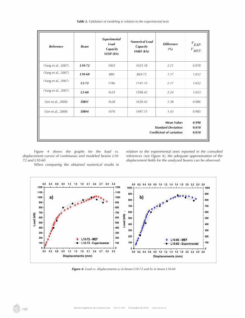
Figure 4 shows the graphs for the load vs. displacement curves of continuous and modeled beams L10-72 and L10-60. When comparing the obtained numerical results in
relation to the experimental ones reported in the consulted references (see Figure 4), the adequate approximation of the displacement fields for the analyzed beams can be observed.
Reference Beam
Experimental
Load
Capacity
VEXP (kN)
Numerical Load
Capacity
VMEF (kN)
Difference
(%)
(Yang et al., 2007) L10-72 1003 1025.18 2.21 0.978
(Yang et al., 2007) L10-60 880 869.72 1.17 1.012
(Yang et al., 2007) L5-72 1786 1747.15 2.17 1.022
(Yang et al., 2007) L5-60 1635 1598.42 2.24 1.023
(Lee et al., 2008) DB#1 1628 1650.42 1.38 0.986
(Lee et al., 2008) DB#4 1476 1497.15 1.43 0.985
Mean Value:
Standard Deviation:
Coefficient of variation:
0.998
0.018
0.018
Table 3. Validation of modeling in relation to the experimental tests
Figure 4. Load vs. displacements a) in beam L10-72 and b) in beam L10-60
Load
(kN)
Load
(kN)
Displacements (mm) Displacements (mm)

Revista Ingeniería de Construcción RIC Vol 31 Nº3 2016 www.ricuc.cl
ENGLISH VERSION.....................................................................................................................................................................................................................................................
Revista Ingeniería de Construcción Vol 31 Nº3 Diciembre de 2016 www.ricuc.cl 169
3. Results and discussion 3.1 Study of the influence of main and vertical
reinforcements Based on beam models L10-72 and L10-60 of the test by (Yang et al, 2007), models for the parametric study of main and vertical reinforcements are made. Configurations with vertical reinforcement (stirrups) are analyzed in these models, and additionally, the behavior for different amounts was studied for each kind of reinforcement, with the aim of evaluating its contribution and influence on the load capacity of these structures. Figure 5 shows the numerical results of the study regarding the influence of the main and vertical reinforcement, which evidence that as the amount of the
main reinforcement increases, the load capacity of the analyzed beams increases. Moreover, the significant increase of the load capacity is observed, when comparing the results of models with low amount of the vertical reinforcement (approx. between 0.2 and 0.3%) in relation to models that do not have this kind of reinforcement, and it is possible to establish that the contribution of this type of reinforcement is significant. The comparison between beam L10-72 (see Figure 5a) and beam L10-60 (see Figure 5b) allows demonstrating that the increase of the vertical reinforcement amount has a greater influence on the beams presenting a higher shear span-effective depth ratio (a/d).
Figure 5. Parametric study of the reinforcement: a) in beam L10-72, b) in beam L10-60
Figure 6. Geometry and diagram of the reinforcement in beam DB#1 tested by (Lee et al., 2008)
Load
cap
acity
(kN
)
Load
cap
acity
(kN
)
Amount of the main reinforcement (%) Amount of the main reinforcement (%)

170 Revista Ingeniería de Construcción Vol 31 Nº3 Diciembre de 2016 www.ricuc.cl
In the numerical study of Figure 7 it is possible to appreciate that when increasing the amount of the main reinforcement, the load capacity is increased, where in amounts higher than 1.0% approximately, curves tend to be asymptotic, thus showing that for high amounts the structure failure is limited by the strength capacity of the concrete strut. It has been observed that for main reinforcement amounts lower than 0.6%, the variation of the load capacity for the four configurations analyzed is not very significant, thus showing that the structural failure is conditioned by the tie (due to its low amount). It is possible to consider that the tie’s amount used in the continuous beam DB#1 tested by (Lee et al., 2008) is insufficient for the geometry, as well as for the properties of materials and the configuration of the vertical reinforcement used in this experimental study, where the significant increase of the load capacity in relation to the red point A (beam DB#1) is evident, when increasing the amount of this kind of reinforcement. All analyzed configurations for vertical reinforcement evidence that the load capacity increases as the diameter of the stirrups increase; this increase is more significant when main reinforcement amounts higher than 0.8% approx. are used, where a better contribution of each reinforcement is achieved. With the aim of verifying these criteria concerning the structural behavior of analyzed continuous beams, readings are made in the reinforcement to evaluate the stress states of steel and identify the bars making more work. It should be noted that the main and vertical reinforcements present yield stresses of 435 MPa and 350 MPa respectively. First, stress readings are made in the reinforcement of the beam model corresponding to the specimen DB#1 (point A in Figure 7). These stress readings are made at different
points located on the main and vertical reinforcement (see Figure 8), showing the stress values obtained at failure (in MPa). Figure 8a shows, on the main reinforcement, at the center of the clear span, values higher than 430 MPa, stresses close to the yield strength of this steel (fy = 435 MPa). On the vertical reinforcement, the stress states are lower, where the steel located in the inside area of the beam makes the biggest contribution, although these values are far from the 350 MPa that represent the yield strength of steel in this type of reinforcement. These stress behaviors confirm that the structural failure is caused by the low amount of the main reinforcement. Consistently with the parametric study undertaken (Figure 7), it is demonstrated that, due to the contribution of the vertical reinforcement, the strength capacity of the concrete strut is higher than the strength capacity of the tie. Figure 8b shows the behavior differences in relation to the contribution and stress states of each type of reinforcement. The main reinforcement at the center of each clear span reaches values close to 370 MPa, which are far from the yield strength for this steel (fy = 435 MPa). In the vertical reinforcement located on the inside area, the stress states are higher with values over 340 MPa on the most stressed stirrups. It should be highlighted that these stresses are close to the yield strength of this steel (fy = 350 MPa). This structural behavior indicates that there is a better joint work with both types of reinforcement, where the structural failure is conditioned by the strength capacity of the concrete strut on the inside area, since the vertical reinforcement located in this area makes its highest contribution and the tie amount is enough to take the maximum stresses.
Figure 7. Parametric study of the main and vertical reinforcement in beam DB#1
Amount of the main reinforcement (%)
Load
cap
acity
(kN
)
Stirrups Stirrups Stirrups Stirrups

Revista Ingeniería de Construcción RIC Vol 31 Nº3 2016 www.ricuc.cl
ENGLISH VERSION.....................................................................................................................................................................................................................................................
Revista Ingeniería de Construcción Vol 31 Nº3 Diciembre de 2016 www.ricuc.cl 171
3.2 Study on the influence of the openings’ position In high RC buildings it is possible to find this type of structures on the lower levels or basements, because deep beams support higher load amounts and contribute to a better redistribution of these loads towards the foundations. The high depth of these beams often requires web openings to allow the passing of pipes and tubes to provide buildings with public utility services. Using the advantages of the numerical simulation, a parametric study is made in order to assess the influence of the position of circular openings of 300 mm diameter located on the beams’ web and for different load diagrams. This study is based on the beam DB#4 tested by (Lee et al., 2008), previously calibrated, where the reinforcement configuration and the materials’ properties are maintained, with the aim of identifying the favorable positions, and to determine in what proportion the load capacity of the structure is affected when these openings are present. First, different positions are analyzed (from opening in position A until K) located in the horizontal and vertical direction (see Figure 9,) and for a diagram with load concentrated on the center of the clear span of the beam. From the analysis of the results obtained from the beam’s
modeling for different opening positions, a set of observations can be made regarding the influence of openings on the load capacity:
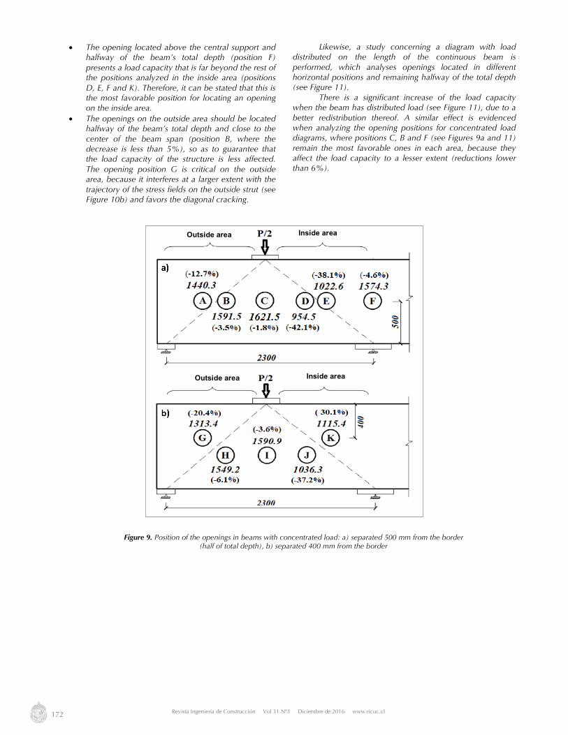
• The most favorable position for locating the opening is at the center of the beam’s span and halfway from the total depth (position C in Figure 9). The opening located in this position does not have a significant influence on reducing the load capacity of the beam, corresponding with a similar behavior when the beam has no opening (1650 kN), where the opening does not interfere with the transmission of the loads towards the supports (see Figure 10a).
• The openings located on the inside area of the beam (positions D, E, J and K) actually affect the load capacity (30 to 40% decrease), compared with openings located on the outside (positions A, B, G and H). The reason is that this is a critical area due to a higher concentration of stress fields (see Figure 10). As expected, the weakening due to the presence of an opening on the inside area entails a significant reduction of the load capacity, since it favors the diagonal cracking.
Figure 8. Stresses in the reinforcement steel in beam model DB#1: a) configuration of point A, b) configuration of point B
Inside area
Inside area
Outside area
Outside area
Outside area
Outside area
172 Revista Ingeniería de Construcción Vol 31 Nº3 Diciembre de 2016 www.ricuc.cl
• The opening located above the central support and halfway of the beam’s total depth (position F) presents a load capacity that is far beyond the rest of the positions analyzed in the inside area (positions D, E, F and K). Therefore, it can be stated that this is the most favorable position for locating an opening on the inside area.
• The openings on the outside area should be located halfway of the beam’s total depth and close to the center of the beam span (position B, where the decrease is less than 5%), so as to guarantee that the load capacity of the structure is less affected. The opening position G is critical on the outside area, because it interferes at a larger extent with the trajectory of the stress fields on the outside strut (see Figure 10b) and favors the diagonal cracking.
Likewise, a study concerning a diagram with load distributed on the length of the continuous beam is performed, which analyses openings located in different horizontal positions and remaining halfway of the total depth (see Figure 11). There is a significant increase of the load capacity when the beam has distributed load (see Figure 11), due to a better redistribution thereof. A similar effect is evidenced when analyzing the opening positions for concentrated load diagrams, where positions C, B and F (see Figures 9a and 11) remain the most favorable ones in each area, because they affect the load capacity to a lesser extent (reductions lower than 6%).
Figure 9. Position of the openings in beams with concentrated load: a) separated 500 mm from the border (half of total depth), b) separated 400 mm from the border
Inside area Outside area
Inside area Outside area

Revista Ingeniería de Construcción RIC Vol 31 Nº3 2016 www.ricuc.cl
ENGLISH VERSION.....................................................................................................................................................................................................................................................
Revista Ingeniería de Construcción Vol 31 Nº3 Diciembre de 2016 www.ricuc.cl 173
Figure 10. Stress distributions (in Pa) on the continuous beam: a) opening position C, b) opening position G and c) opening position K
Figure 11. Position of the openings in beams with distributed load and located halfway of the total depth
Outside strut Outside strut
Inside strut
Inside area Outside area
Diagonal cracks
Cracking area
Cracking area
Outside area

174 Revista Ingeniería de Construcción Vol 31 Nº3 Diciembre de 2016 www.ricuc.cl
4. Conclusions In this work, the combination of numerical simulation and experimentations has allowed arriving at different conclusions that favor the best understanding of the structural behavior of continuous deep beams. The study shows that when increasing the amount of the main reinforcement, the beams’ load capacity is also increased, reaching a limit where the increase of this amount is not relevant, because in these cases the structural failure is conditioned by the strength capacity of the strut. On the other hand, the increase of the vertical reinforcement’s amount equally increases the load capacity in this type of structures, reaching amount limits
where their contribution is not very relevant and the strength capacity of the strut in these cases is conditioned by the cracking and bearing strength of concrete. If it is necessary to make openings in the web of continuous beams, it is recommended to locate them in the areas close to the center of the span or above the central support and they should be located halfway of the total depth of the beam. It has been demonstrated that openings located in the areas close to the struts are the most critical ones, because they interfere to a larger extent with the trajectory of the stress fields and, consequently, they reduce the load capacity in 20 to 40% proportions in relation to the beam without openings
5. References ABAQUS. (2014), User’s Manual, Ver. 6.14-1, Hibbitt, Karlson and Sorensen, Inc. ACI Comitee 318. (2011), Building Code Requirements for Structural Concrete (ACI 318-11) and Commentary. Alsaeq H. M. (2013), Effects of Opening Shape and Location on the Structural Strength of RC Deep Beams with Openings. World Academy of
Science, Engineering and Technology, 7, 1365–1370. Ashour A. F. (1997), Tests of Reinforced Concrete Continuous Deep Beams. ACI Structural Journal, 94(1), 3–12. Bonilla J., Bezerra L., Larrúa R., Mirambell E. y Recarey C. (2015), Numerical modeling with experimental validation applied to the study of
stud connectors behavior in concrete and steel composite structures. Revista Ingeniería de Construcción, 30(1), 53–68. http://dx.doi.org/10.4067/S0718-50732015000100005
Demir A., Ozturk H. y Dok G. (2016), 3D Numerical Modeling of RC Deep Beam Behavior by Nonlinear Finite Element Analysis. Disaster Science and Engineering, 2(1), 13–18.
Eurocode 2 (2004), Design of concrete structures. The European Standard EN 1992-1-1 Hernández H., Bonilla J. y Rodríguez G. (2014), Study of the behavior of composite beams made of concrete and steel by using numerical
simulation. Revista Ingeniería de Construcción, 29(1), 5–21. http://dx.doi.org/10.4067/S0718-50732014000100001 Lee J. y Fenves G. L. (1998), Plactic-Damage Model for Cyclic Loading of Concrete Structures. Journal of Engineering Mechanics, 124(8), 892–
900. http://dx.doi.org/10.1061/(ASCE)0733-9399(1998)124:8(892) Lee J. K., Li C. G. y Lee Y. T. (2008), Experimental Study on Shear Strengh of Reinforced Concrete Continuos Deep Beams with Web Opening.
In The 14th World Conference on Earthquake Engineering (pp. 12–17). Beijing, China. Lubliner J., Oliver J., Oller S. y Oñate E. (1989), A Plastic-Damage Model for Concrete. International Journal of Solids and Structures, 25(3),
229–326. doi:10.1016/0020-7683(89)90050-4 Mohamed H. A. (2013), Experimental and Finite Element Analysis on the Steel Fiber Reinforced Concrete Deep Beams with Web Openings.
International Journal of Engineering and Innovative Technology, 3(2), 529–538. Rodríguez G., Bonilla J. y Hernández J. J. (2012), Aplicación de la simulación numérica al estudio del comportamiento de vigas de gran peralto
de hormigón armado. Revista Ingeniería Civil, 167, 101–116. Rogowsky D. M., MacGregor J. G. y Ong S. Y. (1986), Tests of Reinforced Concrete Deep Beams. ACI Journal, 83(4), 614–623. Saeed J. A. y Yousif A. R. (2013), Test of Fibrous and Nonfibrous Reinforced Concrete Continuous Deep Beams with Web Openings. Journal of
Zankoy Sulaimani, 15(2), 1–20. Subedi N. K. (1998), Reinforced Concrete Two-Span Continuous Deep Beams. Proceedings of the Institution of Civil Engineers, 128(1), 12–
25. http://dx.doi.org/10.1680/istbu.1998.30031 Yang K. H. y Ashour A. F. (2011), Aggregate interlock in lightweight concrete continuous deep beams. Engineering Structures, 33(1), 136–
145. http://dx.doi.org/10.1016/j.engstruct.2010.09.026 Yang K. H., Chung H. S. y Ashour A. F. (2007), Influence of section depth on the structural behaviour of reinforced concrete continuos deep
beams. Magazine of Concrete Research, 59(8), 575–586. http://dx.doi.org/10.1680/macr.2007.59.8.575 Zhang N. y Tan K. H. (2010), Effects of support settlement on continuous deep beams and STM modeling. Engineering Structures, 32(2), 361–
372. http://dx.doi.org/10.1016/j.engstruct.2009.09.019