manual de instalaciÓn installation manual€¦ · brazo telesc pico 280 puerta basculante...
TRANSCRIPT

MANUAL DE INSTALACIÓNINSTALLATION MANUAL
SERIE G ACCIONADORES HIDRÁULICOS ROTATIVOS
PARA PUERTAS BASCULANTES
G SERIESROTATING HYDRAULIC ACTUATORS FOR
UP-AND-OVER DOORS

NORMAS GENERALES DE SEGURIDAD
- Leer atentamente las instrucciones antes de comenzar la instalación del producto. Una instalación incorrecta puede causar dañosirreparables a personas y/o bienes.
- El montaje, las conexiones eléctricas y las regulaciones deben ser efectuadas por personal cualificado respetando las Normas vigentes y según las instrucciones indicadas a continuación.
- Antes de comenzar la instalación, verifique la integridad del producto.
- Los materiales de embalaje deben desecharse sin causar daño al medio ambiente. Manténgase fuera del alcance de los niños por seruna potencial fuente de peligro.
- El motor debe ser destinado exclusivamente al uso para el cual ha sido concebido. Cualquier otro uso debe considerarse inadecuado y por tanto peligroso.
- Los dispositivos de seguridad (células fotoeléctricas, marcos sensibles, topes de emergencia, etc, ) deben instalarse respetando las normas vigentes, así como el ambiente de instalación, el funcionamiento del sistema y la fuerza ejercidas por la puerta. Los dispositivos de seguridad deben de proteger toda la zona de la trayectoria de la puerta para evitar atrapamientos o cizallamiento.
- Aplicar las señalizaciones previstas por las normas vigentes para identificar las zonas peligrosas.
- Antes de conectar la alimentación eléctrica, comprobar que la potencia instalada es superior a la requerida por el automatismo.
- Realizar la conexión a tierra según las normas de seguridad vigentes.
- El instalador deberá informar al usuario sobre funcionamiento automático, manual y de emergencia de la puerta, y entregarle lasinstrucciones de uso.
- El fabricante no podrá ser considerado responsable de los eventuales daños ocasionados por el incumplimiento de estas normas.
CARACTERISTICAS TECNICAS
.- Motor monofásico con condensador permanente
.- Alimentación: 230 V-50Hz
.- Potencia: 200W
.- Intensidad: 1 A
.- Condensador: 10 µF
.- Velocidad de salida: 1.5 r.p.m.
.- Par máximo: 400 Nm
.- Factor protección: IP54
.- Cuadro EP1
Modelo
G 605 Colectivo
Colectivo
Colectivo
NO
SI
NO
G 605 F
G 615
Uso Bloqueo
3
ES
PA
ÑO
L

4
CONDICIONES INICIALES
- La estructura existente debe de ser suficientemente robusta y estable.
- La puerta se debe abrir y cerrar a mano sin ninguna dificultad.
- Corregir los posibles defectos (rozamientos excesivos, falta de engrase, alabeos, etc ).
INSTALACION DEL ACCIONADOR
1.- Colocar los soportes del motor siguiendo el esquema correspondiente.
2.- Colocar la cerradura hidraúlica en la hoja inferior de la puerta (modelo G615).
3.- Colocar el accionador en el soporte, sujetándolo con los tornillos que se suministran con el equipo.
4.- Equilibrar los contrapesos para que no tenga tendencia a subir ni a bajar.
5.- Conectar el accionador al cuadro y probar su funcionamiento.
6.- Comprobar el sentido de giro utilizando los pulsadores abrir y cerrar del cuadro. Si no fuese el correcto intercambiar de posición loscables G1 y G2.
7.- Colocar los herrajes. Para posicionar el eje de transmisión, utilizar los pulsadores abrir y cerrar del cuadro de maniobras.
8.- Regular las presiones de apertura y cierre. La presión aumenta a medida que giramos los tornillos en sentido horario y disminuye silos giramos en sentido antihorario
No apretar los tornillos a tope.
9.- Programar el cuadro según las instrucciones adjuntas en el mismo.
10.-Conectar los distintos accesorios (fotocélula, luz de garaje, etc.)
ELEMENTOS DE SEGURIDADSe recomienda la instalación de elementos adicionales de seguridad (fotocélulas, bandas de seguridad, etc.) con el fin de garantizarla seguridad de las personas u otros objetos que pudieran interferir en el movimiento de la puerta.
DIAGNOSTICO DE AVERIAS
1.- El motor no funciona:
1.1. Verificar si el motor está correctamente conectado.
1.2. Verificar la tensión que llega al motor. (230V AC)
1.3. Verificar si el condensador está conectado.
2.- El motor funciona en un único sentido:
2.1.- Verificar si el común del motor está correctamente conectado.
3.- El motor no tiene fuerza:
3.1. La puerta presenta puntos duros en su recorrido. Desmontar el motor y eliminar dichos puntos hasta que la puerta pueda moverse manualmente sin dificultad.
3.2. El motor no tiene suficiente presión de aceite. Regular la presión.
3.3. Verificar si se ha conectado el condensador y si la capacidad de este es la adecuada (Ver etiqueta del motor)
3.4. Verificar si el tornillo de desbloqueo está en posición de funcionamiento automático.
ES
PA
ÑO
L
Tierra Giro 2 Giro 1 Común

5
4.- En caso de avería del cable de alimentación del motor, este debe ser sustituido por un servicio técnico homologado.
Si tras haber realizado todas las verificaciones y ajustes indicados, persiste la avería, diríjase al distribuidoro al servicio técnico homologado más próximo, indicando con el mayor detalle posible la avería observada.
MANTENIMIENTOExaminar periódicamente la instalación para detectar posibles señales de desgaste, daños o desequilibrios.
Comprobar el perfecto funcionamiento de la puerta.
Cada 6 meses revisar todos los elementos de seguridad.
Comprobar el sistema de desbloqueo manual.
CERTIFICADO DE GARANTIA
Garantizamos el presente equipo durante un periodo de 2 años a partir de la fecha de suministro.
Dicha garantía es aplicable a todo defecto de fabricación.
Es responsabilidad del instalador el hacer llegar el equipo a los servicios técnicos autorizados.
Esta garantía no incluye:
.- Daños ocasionados por una instalación o utilización incorrecta del equipo.
.- Daños ocasionados por una utilización para la cual no haya sido diseñado.
.- Daños provocados por agentes externos o atmosféricos (rayos, inundaciones, etc)
.- Daños ocasionados por la manipulación realizada por personal no autorizado.
PUERTA BASCULANTE ARTICULADA DE APERTURA EXTERIOR CON HERRAJE CENTRAL
ES
PA
ÑO
L

6
PUERTA BASCULANTE ARTICULADA DE APERTURA EXTERIOR
CON HERRAJE CENTRAL Y CERRADURA HIDRÁULICA
PUERTA BASCULANTE ARTICULADA DE
APERTURA EXTERIOR CON HERRAJES LATERALES TELESCOPICOS
ES
PA
ÑO
L
7
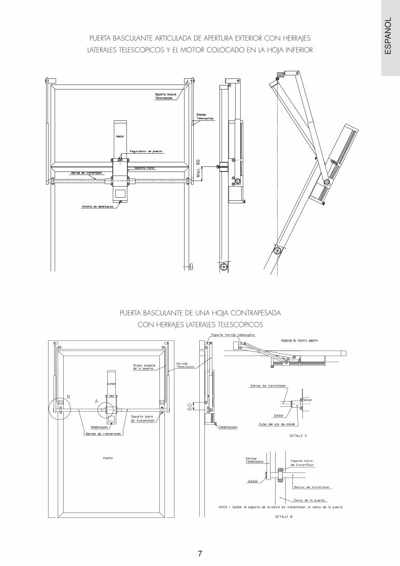
PUERTA BASCULANTE ARTICULADA DE APERTURA EXTERIOR CON HERRAJES
LATERALES TELESCOPICOS Y EL MOTOR COLOCADO EN LA HOJA INFERIOR
PUERTA BASCULANTE DE UNA HOJA CONTRAPESADA
CON HERRAJES LATERALES TELESCOPICOS
ES
PA
ÑO
L

8
200
REGULADOR DE PRESI N (CIERRE) REGULADOR DE PRESI N (APERTURA)
MOTOR
TORNILLO DE SANGRADO
Para instalaciones colectivas,
aflojarlo una vuelta.
Guia de la puerta
Brazo telesc pico
Latiguillo cilindro
Cilindro cerradura
Cerradura puerta
280
Doble Cubo
R
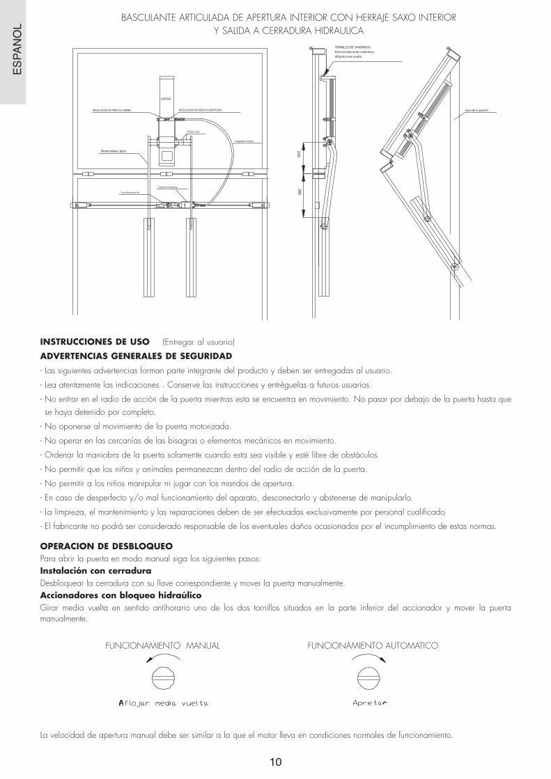
BASCULANTE ARTICULADA DE APERTURA INTERIOR CON HERRAJE
SAXO INTERIOR Y SALIDA A CERRADURA HIDRAULICA
PUERTA BASCULANTE ARTICULADA DE APERTURA INTERIOR CON HERRAJE CENTRAL Y CERRADURA HIDRAULICA
PUERTA BASCULANTE ARTICULADA DE APERTURA INTERIOR CON HERRAJE TELESCOPICO
ES
PA
ÑO
L

99
200
REGULADOR DE PRESI N (CIERRE) REGULADOR DE PRESI N (APERTURA)
MOTOR
TORNILLO DE SANGRADO
Para instalaciones colectivas,
aflojarlo una vuelta.
Guia de la puerta
Brazo telesc pico
280
PUERTA BASCULANTE ARTICULADA DE APERTURA INTERIOR CON HERRAJE TELESCOPICO Y CERRADURA HIDRAULICA
BASCULANTE ARTICULADA DE APERTURA INTERIOR CON HERRAJE CENTRAL
ES
PA
ÑO
L
BASCULANTE ARTICULADA DE APERTURA INTERIOR CON HERRAJE SAXO INTERIOR Y SALIDA A CERRADURA HIDRAULICA
10
INSTRUCCIONES DE USO (Entregar al usuario)
ADVERTENCIAS GENERALES DE SEGURIDAD
- Las siguientes advertencias forman parte integrante del producto y deben ser entregadas al usuario.
- Lea atentamente las indicaciones . Conserve las instrucciones y entréguelas a futuros usuarios.
- No entrar en el radio de acción de la puerta mientras esta se encuentra en movimiento. No pasar por debajo de la puerta hasta que se haya detenido por completo.
- No oponerse al movimiento de la puerta motorizada.
- No operar en las cercanías de las bisagras o elementos mecánicos en movimiento.
- Ordenar la maniobra de la puerta solamente cuando esta sea visible y esté libre de obstáculos.
- No permitir que los niños y animales permanezcan dentro del radio de acción de la puerta.
- No permitir a los niños manipular ni jugar con los mandos de apertura.
- En caso de desperfecto y/o mal funcionamiento del aparato, desconectarlo y abstenerse de manipularlo.
- La limpieza, el mantenimiento y las reparaciones deben de ser efectuadas exclusivamente por personal cualificado
- El fabricante no podrá ser considerado responsable de los eventuales daños ocasionados por el incumplimiento de estas normas.
OPERACION DE DESBLOQUEOPara abrir la puerta en modo manual siga los siguientes pasos:Instalación con cerraduraDesbloquear la cerradura con su llave correspondiente y mover la puerta manualmente.Accionadores con bloqueo hidraúlicoGirar media vuelta en sentido antihorario uno de los dos tornillos situados en la parte inferior del accionador y mover la puerta manualmente.
FUNCIONAMIENTO MANUAL FUNCIONAMIENTO AUTOMATICO
La velocidad de apertura manual debe ser similar a la que el motor lleva en condiciones normales de funcionamiento.
ES
PA
ÑO
L
200
REGULADOR DE PRESI N (CIERRE) REGULADOR DE PRESI N (APERTURA)
MOTOR
TORNILLO DE SANGRADO
Para instalaciones colectivas,
aflojarlo una vuelta.
Guia de la puerta
Brazo telesc pico
Latiguillo cilindro
Cilindro cerradura
Cerradura puerta
280
Doble Cubo

11
GENERAL SAFETY NORMS
- Please read the instructions carefully before installing the product. An incorrect installation can cause irreparable material damage and/or personal injury.
- The assembly, the electrical connections and the regulations must be carried out by qualified personnel in accordance with current norms and the following instructions.
- Before beginning the installation, check the product is OK.
- The packaging material must be disposed of without harm to the environment. Keep out of the reach of children as it is a potential hazard.
- The motor must be used exclusively for what it has been designed. Any other use must be considered inappropriate and dangerous.
- The safety devices (photo-electric cells, sensitive frames, emergency end stops, etc.) must be installed in accordance with the norms in force and the installation environment, the functioning of the system and the force of the door. The safety devices must protect all the area in the sweep of the door to avoid trapping and shearing.
- Use the signs indicated by current norms to identify hazardous areas.
- Before connecting the mains supply, check that the power installed is greater than that required by the automaton.
- Connect to earth as set forth in current safety norms.
- The installer must inform the user of the automatic, manual and emergency functioning of the door and give him/her the instructions for use.
- The manufacturer may not be held responsible for the damages caused by breach of these norms.
TECHNICAL SPECIFICATIONS
.- Single-phase motor with permanent condenser
.- Mains supply: 230V 50 Hz
.- Power: 200W
.- Current: 1 A
.- Condenser 10 µF
.- Output speed: 1.5 r.p.m.
.- Breakdown torque: 400 Nm
.- Protection level: IP54
.- EP1 control panel
1. Hydraulic rotating actuator2. Hexagonal M 10x20 DIN 933 (6)3. 10 DIN 127 GROWER washer (6)4. Motor support5. Condenser
EN
GLI
SH
Model
G 605 Collective
Collective
Collective
NO
YES
NO
G 605 F
G 615
Use Blocking

INITIAL CONDITIONS
- The structure must be sufficiently robust and stable.
- The door must open and close by hand with ease.
- Correct any possible faults (excessive chafing, lack of greasing, warping, etc.)
INSTALLATION OF THE ACTUATOR
1.- Place the motor supports in accord with the corresponding diagram.
2.- Place the hydraulic lock on the bottom leaf of the doo (model G615).
3.- Place the actuator on the support and fasten it with the screws supplied with the appliance.
4.- Balance the counterweights so that it moves neither up nor down.
5.- Connect the actuator to the control panel and check its functioning.
6.- Check the turn direction using the open and close pushbuttons on the control panel. If incorrect, change the positions of the G1 and G2 cables.
7.- Place the hinges. To position the jackshaft, use the open and close pushbuttons on the manoeuvre control panel.
8.- Adjust the open and close pressures. The pressure increases as the screws are turned clockwise and it is reduced if they are turned anti-clockwise.
Do not fasten the screws as tight as possible.
9.- Programme the control panel in accord with the corresponding instructions.
10.- Connect the different accessories (photocell, garage light, etc.).
SAFETY ELEMENTS
It is recommended that you install additional safety elements (photocells, safety bands, etc.) to guarantee the safety of the people or otherobjects that could interfere in the movement of the door.
TROUBLESHOOTING
1.- The motor does not work:
1.1. Check that the motor is connected correctly.
1.2. Check that the power voltage reaches the motor (230V AC).
1.3. Check that the condenser is connected.
2.- The motor works in one direction only:
2.1.- Check that the common switch of the motor is connected correctly.
3.- The motor has no strength:
3.1. The door has hard parts in its sweep. Remove the motor and remove said points until the door can move manually with ease.
3.2. The motor does not have sufficient oil pressure. Check the pressure.
3.3. Check that the condenser has been connected and that the capacity is correct (see label on motor).
3.4. Check that the unblocking screw is in automatic position.
12
Pressure
Open adjustment
Pressure
Close adjustment
EN
GLI
SH
Earth Turn 2 Turn 1 General

13
4.- In case of a fault in the motor power supply cable, it must be replaced by an official technical service.
If, after carrying out all these checks and adjustments, the fault persists, contact your nearest official technicalservice or distributor, providing as many details as possible about the fault.
MAINTENANCERegularly check the installation to detect possible signs of wear and tear, damage or imbalance.
Check the door functions perfectly.
Check the safety elements every 6 months.
Check the manual unblocking system.
CERTIFICATE OF WARRANTY
We guarantee this appliance for a period of 2 years from the date of supply.
Said guarantee is applicable to all manufacturing faults.
The installer is responsible for taking the appliance to the authorised technical services.
This warranty does not include:
.- Damage caused by incorrect installation or use of the appliance.
.- Damage caused by use for which it has not been designed.
.- Damage caused by external or atmospheric agents (lightning, floods, etc.).
.- Damage caused by handling by unauthorised personnel.
EXTERIOR OPENING OVERHEAD DOOR WITH A CENTRAL HINGE
EN
GLI
SH

14
Left arm Right arm
Cylinder hose
Pressure regulators
Motor support
Door lock
Lock Cylinder
Sliding guide
Door guide
Pressure regulators
Motor support
Jackshaft bars
Release lever
Telescopic hingesupport
Telescopicarms
EXTERIOR OPENING OVERHEAD DOOR WITH A LATERAL HINGE AND HYDRAULIC LOCK
EXTERIOR OPENING OVERHEAD DOOR WITH TELESCOPIC LATERAL HINGES
EN
GLI
SH

15
Telescopicarms
Telescopichinge support
Pressure regulators
Motor supportJackshaft bars
Release lever
Door support arm
Jackshaftbar support
Unblocking
Jackshaft bars
DOOR
Telescopicarms
Telescopic hinge support
DOOR OPEN POSITION
Transmission tube
Unblocking
Weld
Output axel end
VIEW A
VIEW B
Telescopic hinge
Weld
Jackshaft bar support
Transmision tube
Door frame
N.B. Weld the Jackshaft bar support to the door frame.
EXTERIOR OPENING OVERHEAD DOOR WITH TELESCOPIC LATERAL HINGES
AND THE MOTOR FITTED TO THE BOTTOM LEAF
EXTERIOR OPENING OVERHEAD DOOR WITH A COUNTERWEIGHTED LEAF
AND TELESCOPIC LATERAL HINGES
EN
GLI
SH

16
200
PRESSURE REGULATOR (CLOSING) PRESSURE REGULATOR (OPENING)
MOTOR
BLEED SCREWFor community installations,loosen one turn.
Door guide
Telescopic arm
Cylinder cable
Lock cylinderDoor lock
280
Double hub
PRESSURE REGULATOR (CLOSING) PRESSURE REGULATOR (OPENING)
Drag bushingWeld to arm
Guide rod
Telescopic arm
Central door cross piece
Telescopic arm support
Central door cross piece
Door guide
BLEED SCREWFor community installations,loosen one turn.
INWARD-OPENING ARTICULATED OVERHEAD DOOR WITH CENTRAL FITTING AND HYDRAULIC LOCK
INWARD-OPENING ARTICULATED OVERHEAD DOOR WITH TELESCOPIC FITTING
EN
GLI
SH

17
PRESSURE REGULATOR (CLOSING) PRESSURE REGULATOR (OPENING)
Drag bushingWeld to arm
Guide rod
Central door cross piece
Telescopic arm support
Central door cross piece
Door guide
BLEED SCREWFor community installations,loosen one turn.
Telescopic arm
Door lock
Cylinder cable
Lock cylinder
PRESSURE REGULATOR (CLOSING) PRESSURE REGULATOR (OPENING) Door guide
Telescopic arm
BLEED SCREWFor community installations,loosen one turn.
200
MOTOR
280
INWARD-OPENING ARTICULATED OVERHEAD DOOR WITH TELESCOPIC FITTING AND HYDRAULIC LOCK
INWARD-OPENING ARTICULATED OVERHEAD DOOR WITH CENTRAL FITTING
EN
GLI
SH

18
INSTRUCTIONS FOR USE (Give to user)
GENERAL SAFETY WARNINGS
- The following warnings form an integral part of the product and must be given to the user.
- Read the indications carefully. Keep the instructions and give them to future users.
- Do not enter the radius of action of the door while it is moving. Do not pass under the door until it has come to a stop.
- Do not apply force against the movement of the motorised door.
- Do not work near the hinges or moving mechanical parts.
- Open and close the door only when it is visible and free from obstacles.
- Do not let children and animals in the radius of action of the door.
- Do not let children handle or play with the control.
- In case of faults and/or malfunctioning of the appliance, disconnect it and refrain from using it.
- Cleaning, maintenance and repairs must be carried out exclusively by qualified personnel.
- The manufacturer shall not be held responsible for any damage resulting from breach of these norms.
UNBLOCKING OPERATIONTo open the door in manual mode, proceed as follows:Installation with lockUnblock the lock with the corresponding key and move the door manually.Actuators with hydraulic blockingTurn one of the screws on the bottom of the actuator anti-clockwise and move the door manually.
MANUAL FUNCTION AUTOMATIC FUNCTION
Loosen half a turn Tighten
The speed of the manual opening must be similar to that of the motor under normal working conditions.
EN
GLI
SH
INWARD-OPENING ARTICULED OVERHEAD DOOR WITH INTERIOR FITTING AND HYDRAULIC LOCK EXIT
PRESSURE REGULATOR (CLOSING) PRESSURE REGULATOR (OPENING) Door guide
BLEED SCREWFor community installations,loosen one turn.
Telescopic arm
Door lock
Cylinder cable
Lock cylinder
200
MOTOR
280
Double hub

MSG - 001/4Goi Design - Zumárraga