imnsa - ministerio de agricultura y ganadería · 2018-03-13 · el puente se diseño para una luz...
TRANSCRIPT

IMNSA
INGENIEROS CONSULTORES S.A. SAN JOSE, COSTA RICA TEL. (506) 2234-1587 FAX (506) 2225-9551 APDO 118-2050 E-MAIL: [email protected]
MMIINNIISSTTEERRIIOO DDEE AAGGRRIICCUULLTTUURRAA YY GGAANNAADDEERRÍÍAA
CONTRATACIÓN DE EMPRESA PARA REALIZAR EL DISEÑO FINAL Y PLIEGO DE PUENTES (BLANCH,
VALENTE, TUNEL Y TRANQUILINO) EN LA CARRETERA QUE CONDUCE A GANDOCA EN EL CANTÓN DE
TALAMANCA
SITIO QUIEBRA TRANQUILINO
NOVIEMBRE, 2012 Informe preparado por:
IMNSA INGENIEROS CONSULTORES S.A.
Ingenieros de Diseño Estructural:
Eduardo Hernández Q.
Joseph Jiménez E.

IMNSA
INGENIEROS CONSULTORES S.A. SAN JOSE, COSTA RICA TEL. (506) 2234-1587 FAX (506) 2225-9551 APDO 118-2050 E-MAIL: [email protected]
Tabla de Contenido
1. Información preliminar
a. Estudio de suelos
b. Topografía
2. Descripción del proyecto
3. Estructuración del proyecto
4. Materiales y Parámetros de diseño
5. Cargas generales
a. Carga muerta por etapas
b. Carga viva peatonal
c. Carga viva vehicular para diseño
6. Diseño de elementos
a. Superestructura
i. Momento y cortante último
ii. Revisión de capacidad de la viga en sección simple para etapa
constructiva
iii. Sección Compuesta y revisión de esfuerzo en losa de concreto trabajando
en sección compuesta con combinación de carga que rige el diseño
iv. Revisar pandeo en el alma y necesidad de atiesadores
verticales/horizontales

IMNSA
INGENIEROS CONSULTORES S.A. SAN JOSE, COSTA RICA TEL. (506) 2234-1587 FAX (506) 2225-9551 APDO 118-2050 E-MAIL: [email protected]
v. Revisión de fatiga
b. Subestructura
i. Diseño de aletones
ii. Diseño de losa de aproximación
iii. Diseño de bastión
1. Diseño de fundaciones

IMNSA
INGENIEROS CONSULTORES S.A. SAN JOSE, COSTA RICA TEL. (506) 2234-1587 FAX (506) 2225-9551 APDO 118-2050 E-MAIL: [email protected]
Información preliminar Se adjunta estudio de suelos y levantamiento topográfico del sitio. Descripción del proyecto El puente se ubica sobre la Quebrada Tranquilino en la provincia de Limón, cantón de Talamanca en el distrito de Bratsi. El puente se diseño para una luz de 30 m y un ancho total de 6.7 m. Cuenta con un carril de 4.3 m y dos aceras de 1.2m con barandas tipo Flex Beam. La superestructura es una losa de concreto reforzado de 20 cm de espesor con cuatro vigas de acero W36x194 y canales de acero como diafragmas, dos bastiones en sus extremos de concreto reforzado colado en sitio los cuales cuentan con pilotes de acero los cuales serán hincados en el sitio. El alineamiento horizontal del puente es recto, se eleva la rasante para elevar el puente y cuenta con losas de aproximación en ambos lados.
Fig. 1 Modelo 3D SAP2000

IMNSA
INGENIEROS CONSULTORES S.A. SAN JOSE, COSTA RICA TEL. (506) 2234-1587 FAX (506) 2225-9551 APDO 118-2050 E-MAIL: [email protected]
Estructuración
Superestructura Se estructura el puente con una luz de 30 m con cuatro vigas W36x194 y diafragmas canales en C12x30. Se considera sección compuesta con una losa de concreto reforzado de 20 cm de espesor. Las vigas se apoyan sobre asientos elastoméricos, placas de neopreno reforzadas con láminas de acero (ver detalle en planos).
Subestructura La subestructura del puente trata de dos bastiones de concreto colados en sitio, lo cuales se diseñan con aletones y se indica zampeado de protección.
Fundaciones Los bastiones se encuentran apoyados sobre fundaciones típicas de concreto reforzado.
Materiales Concreto estructural: Losa de concreto: f´c =280 kg/cm2
Bastiones: f´c =280 kg/cm2 Acero de refuerzo: Grado 60, ASTM A615 Acero de vigas: Grado 50 vigas principales, ASTM A50 Grado 36 otros elementos, ASTME A36 Parámetros de Diseño
Tipo de estructura: vigas simplemente apoyadas Zona sísmica: III Tipo Suelo: S3 Aceleración de diseño: 0.36g
Diseño de Elementos Ver hojas de cálculo adjuntas

Proyecto: Puente Tranquilino
Ubicación: Talamanca, LimónCargas de diseño 1/1
Longitud 30 m
Ancho calzada 4,3 m
Ancho aceras (dos) 1,2 m
Cargas muertas kg/m2 kg/m Peso total
540,0 2322 69.660,0
960,0 2304 69.120,0
24,3 730,0
95,5 410,7 12.319,5
Σ 151.829,5
CantidadLong. o
área kg/m o kg Peso total
4 30 289,1 34.687,2
30 1,6 44,7 2.185,8
40 0,1 8,6 343,4
16 0,4 67,3 1.076,1
16 0,2 36,1 577,2
32 0,2 24,0 768,6
Σ 39.638,4
PESO TOTAL Peso total
Losa de rodamiento y otros 151.829,5 kg
39.638,4 kg
Total 191.467,9 kg
190.857 kg Diferencia % 0% OK
Carga muerta por etapas
Carga muerta de losa 540 kg/m2
Carga viva peatonal
Carga viva peatonal 400 kg/m2
Carga viva vehicular para diseño Factores de carga
Impacto 33 %
HL‐93 AASHTO LRFD 2010 Frenado 25 %
TPD No hay
Combinaciones de Carga
Se revisan todas las combinaciones de carga según Cap.3 AASHTO
Factores de reducción según AASHTO, ACI y AISC
Estructura de acero
Masa SAP 2000
Placas de empalmes
Placas de empalmes
Placas de empalmes
W36x194
C 12x30
Atiesadores
Calzada (22,5cm)
Baranda tipo Flex-beam
Superestructura de acero
Elementos
Aceras (40 cm)
Asfalto (5cm)

Proyecto: Puente Tranquilino
Ubicación: Talamanca, LimónFactores de distribución 1/4
Concreto reforzado Vigas de acero
f`c = 280 Kg/cm² fy = 3500 Kg/cm²
Ec = 252671 Kg/cm² Es = 2043186 Kg/cm²
fy = 4200 Kg/cm²
L = 20 m
Losa = 0,2 m
bf = 0,36 m
0,9 m
Vigas interiores Vigas exteriores
L/4 = 5 m 3,4 m
2,6 m 2,1 m
1,8 m 1,8 m
1,8
Revisión solamente viga de acero
Sección propuesta 43 W36X194
Viga Peso (lbf/ft) Area (in2) d (in) bf (in) tf (in) tw (in)
W36X194 194 57 36,5 12,1 1,26 0,765
Ix (in4) Sx (in3) Zx (in3) rx (in)
12100 664 767 14,6
Viga Peso (kgf/m) Area (cm2) d (mm) bf (mm) tf (mm) tw (mm)
W36X194 289,3 367,7 927,1 307,3 32,0 19,4
Ix (cm4) Sx (cm3) Zx (cm3) rx (cm)
503640,0 10881,0 12568,9 37,1
Factores de distribución de cargas vivas en momento posivitos
ts = 8 in
s = 2 in
n = 8
eg = 24 in
Kg = 368.895 in4
2gvigavigag eAInK

Proyecto: Puente Tranquilino
Ubicación: Talamanca, LimónFactores de distribución 2/4
Viga interior ‐ Condiciones de servicio y capacidad
S = 5,9 ft Espaciamiento entre vigas
L = 65,6 ft
Dm = 0,54 Factor de distribución varios carriles
Dm = 0,40 Factor de distribución un carril
0,54 Rige
Ec. Para varios carriles
Ec. Para un carril
Dv = 0,66
Dv = 0,60
0,66 Rige
Ec. Para varios carriles
Ec. Para un carril
Flexión
Nota: se debe hacer una corrección cuando los puentes
tienen sesgos de mas 30°, ver AASTHO 4.6.2.2.
Cortante
1.0
3
2.06.0
125.9075.0
s
gM tL
KL
SSD
1.0
3
3.04.0
121406.0
s
gM tL
KL
SSD
2536.0 SD V
235122.0 SSDV

Proyecto: Puente Tranquilino
Ubicación: Talamanca, LimónFactores de distribución 3/4
Viga exterior ‐ Condiciones de servicio y capacidad
# carrilles 1
Dm = 0,59
ft
m = 1,2 Tabla 3.6.1.1.2‐1 AASHTO
e = 1,1 Tabla 4.6.2.2.2.d‐1 AASHTO de = 3,1 ft
Dm = 0,45
0,59
Análisis especial
R = 0,43 Nl = 1 # carriles cargados
Nb = 4 # de vigas
x1 = 3,0
x2 = 8,9
x3 = 14,8
Carriles m Dm
R = 0,34 1 1,2 0,41
R = 0,51 2 1 0,51
0,51
e = 0,94
Dv = 0,63
Dv = 0,56
Análisis especial
Flexión
Ancho de
camión de 6
Dist de las vigas al centro de gravedad4.6.2.2.d‐1 AASTHO
Cortante
Xext = 14,7 Dist del centro de gravedad de las vigas
al centro de la viga exterior
e = 7,4
Excentrididad entre el camión de
diseño y el centro de gravedad de las
vigas
15.05.0 mS
aSD m
b
L
N
Next
b
L
x
e
XN
NR
2

Proyecto: Puente Tranquilino
Ubicación: Talamanca, LimónFactores de distribución 4/4
Dv = 0,51
0,63 RIGE
Factor de distribución por fatiga
Flexión Cortante
Dm = 0,49 Dv = 0,52
Factor de distribución para deflecciones debido a carga viva
Se asume que todas las vigas se deflectan en conjunto
Df = 0,33 Nl = 2
Nb = 6
m = 1
Viga interior Viga exterior
Flexión 0,54 0,59
Cortante 0,66 0,63
Fatiga (flexión) 0,49 0,49
Fatiga (cortante) 0,52 0,52
Deflección 0,33 0,33
Factores de distribución de cargas vivas en momento posivitos
Nota: las vigas son iguales en ambas zonas por lo tanto poseen los mismos factores de distribución
Factor dinámico 1,33 Tabla 3.6.2.1‐1 AASHTO
Tabla resumen de factores de distribución para momentos positivos

Proyecto: Puente Tranquilino
Ubicación: Talamanca, LimónDIAGRAMAS MOMENTO Y CORTANTE ULTIMOS
Dist (m) Ton‐m Dist (m) Ton‐m
0,0 6,3 0,0 1,7
2,5 122,6 2,5 131,6
2,5 123,2 2,5 131,4
5,0 229,4 5,0 231,7
5,0 230,1 5,0 231,5
7,5 313,7 7,5 305,7
7,5 314,2 7,5 305,6
10,0 367,0 10,0 363,1
10,0 367,4 10,0 363,1
12,5 401,8 12,5 395,5
12,5 402,2 12,5 395,4
15,0 414,7 15,0 401,8
15,0 414,9 15,0 401,8
17,5 402,5 17,5 395,5
17,5 402,4 17,5 395,7
20,0 368,2 20,0 363,3
20,0 368,1 20,0 363,4
22,5 315,5 22,5 306,0
22,5 315,2 22,5 306,2
25,0 231,7 25,0 232,0
25,0 231,3 25,0 232,4
27,5 125,0 27,5 132,1
27,5 124,4 27,5 132,6
30,0 0,2 30,0 0,2
MAX 414,9 MAX 401,8
Vigas exteriores Vigas internas
0,050,0100,0150,0200,0250,0300,0350,0400,0450,0
0,0 5,0 10,0 15,0 20,0 25,0 30,0
M (T‐M)
DIST (M)
Mu
VigasExteriores
VigasInternas

Proyecto: Puente Tranquilino
Ubicación: Talamanca, LimónDIAGRAMAS MOMENTO Y CORTANTE ULTIMOS
Vigas exteriores
Dist (m) Ton Ton Dist (m) Ton Ton
0,0 ‐52,7 ‐29,4 0,0 ‐59,1 ‐29,6
2,5 ‐47,3 ‐24,8 2,5 ‐50,1 ‐23,1
2,5 ‐46,6 ‐24,4 2,5 ‐48,7 ‐22,5
5,0 ‐40,6 ‐19,2 5,0 ‐41,0 ‐16,0
5,0 ‐39,5 ‐18,7 5,0 ‐40,4 ‐15,1
7,5 ‐33,3 ‐13,1 7,5 ‐33,1 ‐7,5
7,5 ‐29,4 ‐11,8 7,5 ‐35,0 ‐9,6
10,0 ‐23,8 ‐5,8 10,0 ‐27,2 ‐2,7
10,0 ‐23,0 ‐4,9 10,0 ‐26,3 ‐2,2
12,5 ‐17,1 1,1 12,5 ‐19,0 4,9
12,5 ‐16,1 1,7 12,5 ‐18,4 5,7
15,0 ‐10,1 7,4 15,0 ‐11,3 13,3
15,0 ‐7,3 10,2 15,0 ‐13,3 11,3
17,5 ‐1,6 16,2 17,5 ‐5,7 18,5
17,5 ‐1,0 17,2 17,5 ‐4,9 19,0
20,0 5,0 23,1 20,0 2,3 26,4
20,0 5,9 23,9 20,0 2,7 27,2
22,5 11,8 29,5 22,5 9,6 35,0
22,5 13,1 33,4 22,5 7,6 33,1
25,0 18,7 39,6 25,0 15,1 40,4
25,0 19,2 40,7 25,0 16,0 41,1
27,5 24,4 46,7 27,5 22,5 48,8
27,5 24,8 47,3 27,5 23,1 50,2
30,0 29,4 52,7 30,0 29,6 59,2
MAX ‐52,7 52,7 MAX ‐59,1 59,2
Vigas internas
‐80,0
‐60,0
‐40,0
‐20,0
0,0
20,0
40,0
60,0
80,0
0,0 5,0 10,0 15,0 20,0 25,0 30,0Vu (ton)
Dist (m)
Vu
Viga ExteriorVmin
Viga exteriorVmax
Viga internaVmin
Viga internaVmax

Proyecto: Puente Tranquilino
Ubicación: Talamanca, LimónCALCULO PARA SECCIÓN SIMPLE(Vigas W) 1/2
Dimensiones puente Vigas de acero
L puente = 20 m fy = 3.500 Kg/cm²
ts = 0,2 m Es = 2,04E+06 Kg/cm²
S = 1,63 m
Sección propuesta 43 W36X194
Viga Peso (lbf/ft) As (in2) d (in) bf (in) tf (in) tw (in)
W36X194 194 57 36,5 12,1 1,26 0,765
Ix (in4) Sx (in3) Zx (in3) rx (in) ry (in)
12100 664 767 14,6 2,56
Iy (in4) Sy (in3)
375 61,9
Viga Peso (kgf/m) As (cm2) d (mm) bf (mm) tf (mm) tw (mm)
W36X194 289,3 367,7 927,1 307,3 32,0 19,4
Ix (cm4) Sx (cm3) Zx (cm3) rx (cm) ry (cm)
503640,0 10881,0 12568,9 37,1 6,5
h/tw = 44,4
3.76 √(E/fy) = 90,6 SECCION COMPACTA

Proyecto: Puente Tranquilino
Ubicación: Talamanca, LimónCALCULO PARA SECCIÓN SIMPLE(Vigas W) 2/2
Revisión a flexión
Mu = 414,9 ton‐m
Capacidad a flexión viga W AISC Tabla 3.2
фMn (kip‐ft) фMn (ton‐m)
W36X194 2.880 395 NO OK
Revisión del cortante
Vu = 59,2 ton
701,86 kip
319,0 ton OK
Deflecciones
AISC Tabla 3‐20
Ix (in4) Ix (cm4)
W36X194 12.100 503.640
Ton‐m kip‐ft
Mcm = 266,9 1.294,0
C1 (w) 161 Factor de carga
7,26 cm L/240 = 8,3 cmΔcm = Mcm*L^2/C*Ix
фVn = 0.9*0.6*Fy*Aw

Proyecto: Puente Tranquilino
Ubicación: Talamanca, LimónOTROS
Revisión por Pandeo:
Lb = 5,0 m fy = 50,0 ksi
ry = 2,56 in J = 22,2 in
rts^2 = 10,3 in J*c/Sx*h = 0,000916
Lb = 16,4 ft
Lp = 9,0 ft
Lr = 28,0 ft
(Lb‐Lp)/(Lr‐Lp)= 0,39
Sx = 664 in3
Zx = 767 in3
Mp = 38350 kip‐in
Cb = 1,0
Mn = 32471 kip‐in
ØMn = 2435 kip‐ft
Mcm = 1294,0 kip‐ft Ok
ØMn = 2880 kip‐ft Según Tabla 3.2 AISC
Atiesadores: No son necesarios, viga cumple con sección compacta
Fatiga: No hay registro del tránsito promedio diario en la zona TPD*
Viga cumple con sección compacta

Proyecto: Puente Tranquilino
Ubicación: Talamanca, Limón
CALCULO PARA
SECCIÓN COMPUESTA (Vigas W)1/2
Concreto reforzado Vigas de acero
f`c = 280 Kg/cm² fy = 3500 Kg/cm²
Ec = 252671 Kg/cm² Es = 2043186 Kg/cm²
fs = 4200 Kg/cm²
L puente = 30 m S = 1,63 m
ts = 0,225 m
Ancho efectivo
L/8 = 3,75 m
S/2 = 0,82 m
b = 4,00 m
aefec = 0,82 m
Sección propuesta 43 W36X194
Viga Peso (lbf/ft) As (in2) d (in) bf (in) tf (in) tw (in)
W36X194 194 57 36,5 12,1 1,26 0,765
Ix (in4) Sx (in3) Zx (in3) rx (in)
12100 664 767 14,6
Viga Peso (kgf/m) As (cm2) d (mm) bf (mm) tf (mm) tw (mm)
W36X194 289,3 367,7 927,1 307,3 32,0 19,4
Ix (cm4) Sx (cm3) Zx (cm3) rx (cm)
503640,0 10881,0 12568,9 37,1
h/tw = 44,4
3.76 √(E/fy) = 90,6 SECCION COMPACTA
Fviga = As*fy 1.287.094 kg
Fconc = 0.85*fc*2*a*ts 872.865 kg
Rige = 872.865 CONCRETO
a = F/(0.85*fc*aefec) 22,50 cm NO OK, a > ts
8,86 in
y = d/2 + ts ‐ a/2 57,6 cm
Capacidad a flexión sección compuesta
ф= 0,85 Mu = 3001,1 kip‐ft OK
Mn = 502.814 kg‐m
фMn= 427.392 kg‐m 43566,952
3.085 kip/ft Y1= 0 in
Y2= 4,4 in
Capacidad a flexión viga W AISC Tabla 3.2
фMn (kip‐ft) фMn (ton‐m) фMn (kip‐ft) фMn (kg‐m)
W36X194 2.880 395 W36X194 4.760 659.476
Capacida a flexión sección compuesta AISC
Tabla 3‐19

Proyecto: Puente Tranquilino
Ubicación: Talamanca, Limón
CALCULO PARA
SECCIÓN COMPUESTA (Vigas W)2/2
Revisión del cortante
Vu = 131,44 kip
701,86 kip
Deflecciones
n = Es/Ec 8,1
aefec = 0,10 m
Sección A (cm2) y (cm) A*y (cm3) A*y^2 (cm4) Io (cm4) I (cm4)
Losa 226,8 104,0 23.575 287.919 9.567 297.486
Viga W 367,7 46,4 17.047 177.548 503.640 681.189
∑ 595 40.622 978.675
y= 68,3 cm h= 115,2 cm
AISC Tabla 3‐20
I sec comp = 978.675 cm4 Ix (in4) Ix (cm4)
I sec comp = 23.513 in4 W36X194 30.300 1.261.181
Mcm = 1.294 kip‐ft
Mcv = 790 kip‐ft
C1 (w) 161 Factor de carga
6,53 cm L/240 = 12,5 cm
10,52 cm L/800 = 3,8 cm
8,07 cm
Nota: Deflección CM+CV no cumple por lo tanto debe
hacerse una contraflecha a las vigas principales
Δcm = Mcm*L^2/C*Ix
Δ = Mser*L^2/C*Isec comp
фVn = 0.9*0.6*Fy*Aw
AISC Ec. 3‐3
SAP 2000 Δ =

Proyecto: Puente Tranquilino
Ubicación: Talamanca, LimónCONECTORES 1/1
Concreto reforzado Vigas de acero
f`c = 280 Kg/cm² fy = 3500 Kg/cm²
Ec = 252671 Kg/cm² Es = 2043186 Kg/cm²
fs = 4200 Kg/cm²
L = 20 m S = 1,63 m
ts = 0,2 m
Ancho efectivo
L/8 = 2,50 m
S/2 = 0,82 m
b = 4,00 m
aefec = 0,82 m
Diseño de conectores de cortante Ver AISC I 8.2a
ф < 2.5*tf 80,0 mm
ф = 22 mm
Lc > 4*ф 88 mm
s max = 200 mm
6 ф = 132 mm
8 ts = 1600 mm
s max = 900 mm
0.85*fc*Ac = 775.880 kg
As*fy = 1.287.094 kg
Pernos AISC I 8‐1
Fu = 4550 kg/cm2
Asa = 3,07 cm2
12.911 kg Rg = 1
10.476 kg Rp = 0,75
Qn = 10.476 kg
# de pernos = 74,1
@ 0,27 m
Canales AISC I 8‐2 MC5x9
tf = 0,81 cm
39.241 kg tw = 0,83 cm
19,8 la = 12,7 cm
1,0 m
0.5 Asa*√(fc*Ec) < Rg*Rp*Asa*Fu
0.5 Asa*√(fc*Ec) =
Rg*Rp*Asc*Fu =
0.3(tf + 0.5 tw)*Lc*√ (fc*Ec) =
# de canales
@

Proyecto: Puente Tranquilino
Ubicación: Talamanca, LimónLOSA DE CONCRETO 1/2
Concreto reforzado Refuerzo acero
f`c = 280 Kg/cm² fy = 4200 Kg/cm²
Ec = 252671 Kg/cm² Es = 2043186 Kg/cm²
L = 20 m S = 1,63 m
ts = 0,2 m
AASHTO Tabla A4‐1
0 9 24
5,3 4,67 4,06 2,41 0,98
0 9 24
1,63 2,10 1,83 1,09 0,44
AASHTO 9.7.2.5
As min = 6,00 cm2/m
As min por capa = 4,00 cm2/m
#5 @ 20cm A.D. 9,90 cm2/m
фMn aprox = 4,72 ton‐m Ok
фVc aprox = 8,07 ton
Momento +
(kip‐ft/ft)
Momento ‐ (kip‐ft/ft)S (ft) =
S (m) =Momento +
(ton‐m/m)
Momento ‐ (ton‐m/m)

Proyecto: Puente Tranquilino
Ubicación: Talamanca, LimónLOSA DE CONCRETO 2/2

NSBA SPLICE, Analysis and Design Softwarefor Bolted Splices of Steel Bridges
Version [email protected]
[email protected]. Firas I. Sheikh Ibrahim, PE
Courtesy ofHirschfeld Industries
http://www.hirschfeld.comNational Steel Bridge Alliancehttp://www.steelbridges.org
©2012 National Steel Bridge Alliance
PROJECT NAME: TunelPROJECT NUMBER: IMNSA
I. SPLICE ANALYSIS SUMMARY:
1. Top Flange Splice meets ALL Design Requirements.
2. Bottom Flange Splice Requirement Violations:Plate Capacity Violations (See Section 4.2.1):*Required Capacity (Inner Splice Net Area)
3. Web Splice Requirement Violations:Bolt Capacity Violations (See Section 4.3.1):
1. PROBLEM DEFINITION:=======================
Analysis Type: Splice Capacity CheckUnit Preference: Customary (US)AASHTO Analysis/Design Method: AASHTO LRFD 6th EditionSpan Type: Simple Span
Load Factors (AASHTO 3.4.1&2):Strength I DC Maximum/Minimum: 1.25, 0.90Strength I & IV DW Maximum/Minimum: 1.50, 0.65Strength I LL+IM: 1.75Strength IV DC Maximum/Minimum: 1.50, 0.90Service II DC and DW: 1.00Service II LL+IM: 1.30Service II DW Minimum: 0.00Fatigue-I LL+IM: 1.50Fatigue-II LL+IM: 0.75Fatigue Life : 75Construction Loads (Permanent Loads): 1.25Construction Loads (Temporary Loads): 1.50

Resistance Factors (AASHTO 6.5.4.2):Flexure, Øf: 1.00Shear, Øv: 1.00Compression, Øc: 0.90Tension Net Fracture, Øu: 0.80Tension Gross Yield, Øy: 0.95Bolt Bearing, Øbb: 0.80Bolt Shear, Øs: 0.80Block Shear, Øbs: 0.80
Minimum Longitudinal Bolt Rows: 2 (web), 2 (flange)Inner/Outer Splice Area Variance: 10.0 % (maximum)
Load Modifier (AASHTO 1.3.2.1): 1.00Ductility Factor : 1.00Redundancy Factor : 1.00Operational Importance Factor: 1.00
Applied Minimums (AASHTO 6.13.6.1.4): AASHTO LRFD 6th Ed. (Flexure &Shear)
Unfactored Loads at the Splice Centerline:Component: Moment (K·ft) Shear (Kip)DC1 1,294.0 52.6DC0 601.5 24.4CL 60.2 2.4DC2 106.4 4.3DW 0.0 0.0+(LL+I) 96.0 4.0-(LL+I) 0.0 4.0FATIGUE+(LL+I) 14.4 0.6FATIGUE-(LL+I) 0.0 0.6
Left Plate Girder Properties:Flange Steel/Web Steel: M270 Gr50Top Flange Dimension: 1.25 in × 12.0938 inBottom Flange Dimension: 1.25 in × 12.0938 inWeb Dimension: 0.75 in × 34.0 inWeb Shear Nominal Strength: 131.4 K
(Right Girder is Identical to Left)
Number of Flange Splice Plates: 3Girder Clear Gap: 0.1875 inADTT/Truck Lane Availability: 1260, 1-Lane
Connection Bolt Properties:Bolt Designation: 7/8 in AASHTO M164 (A325)Design Bolt Hole Size: .9375 inMinimum Pitch/Gage Spacing: 3 inMinimum Edge/End Distance: 1.5 in
Faying Surface Class: BBolt Slip Resistance: 39.0 K/bolt/2planesWeb Bolt Threads: Excluded

Web Bolt Shear Resistance: 55.4 K/bolt/2planesFlange Bolt Threads: ExcludedFlange Bolt Shear Resistance: 55.4 K/bolt/2planes
Concrete Slab Design Type: Normal Weight ConcreteConcrete Slab Properties:Reinforcing Steel Area: 3.06 in²Reinforcing Steel Centroid: 4.0 in (from slab bottom)Reinforcing Steel Fy: 60.0 ksiCompressive Strength, fc': 4.0 ksiSlab Thickness: 8.0 inEffective Width: 32.0 inHaunch Depth: 0.25 in (above top of web of left
girder)
Span Length: 98.0 ft
Top Flange Splice Properties:Plate Steel: M270 Gr50Outer Plate Dimension: 1 - 1 × 10 × 63 inInner Plate Dimension: 2 - .75 × 3.5 × 63 inLongitudinal Bolt Pattern: 10 rows of 2 Bolts @ 3 in PitchDimensions X1, X2, X3, X4: 6 in, 1.5 in, 7 in, 1.5 in
Bottom Flange Splice Properties:Plate Steel: M270 Gr50Outer Plate Dimension: 1 - 1 × 10 × 63 inInner Plate Dimension: 2 - .75 × 3.5 × 63 inLongitudinal Bolt Pattern: 10 rows of 2 Bolts @ 3 in PitchDimensions X5, X6, X7, X8: 6 in, 1.5 in, 7 in, 1.5 in
Web Splice Properties:Plate Steel: M270 Gr50Plate Dimension: 2 - .75 × 19.6875 × 30 inLongitudinal Bolt Pattern: 3 rows of 10 Bolts @ 3 in SpacingDimensions X9, X10, X11: 4.6875 in, 1.5 in, 3 in
Determination of smaller girder:
I for left steel girder = 11,852.5 in4
I for right steel girder = 11,852.5 in4
I × Fy left girder = 11,852.5 × 50 = 592,623.1
I × Fy right girder = 11,852.5 × 50 = 592,623.1
I × Fy left girder <= I × Fy right girder
=> Treat the left girder as the smaller girder
Calculated Section Properties for the Left (Smaller) Girder:

Section Type: Noncomposite -Composite* nComposite3nComposite
I (in4) 11,852.5 13,321.0 22,314.416,441.9
S top of Steel (in³) 649.4 780.0 2,221.81,123.4
S top of web (in³) 697.2 841.6 2,537.61,228.3
S bottom of web (in³) 697.2 733.1 885.3797.6
S bottom of steel(in³) 649.4 685.9 843.4752.0
Effective Bottom Flange Tension Area for Left (Smaller) Girder for(+) Strength:
(AASHTO 6.13.6.1.4c-2)Ae = [(Øu×Futf)/(Øy×Fytf)]An <= Ag in²Ae = 14.0 <= 15.1 in²Ae = 14.0 in²Ae/Ag = 0.925
Effective Bottom Flange Tension Area for Right (Larger) Girder for(+) Strength:
Ae = 14.0 in²Ae/Ag = 0.925
*includes the concrete reinforcing steel
2. DESIGN LIMIT STATES:========================
2.1 During Construction (AASHTO 3.4.2):________________________________________
Mconstruction: 1,707.7 K·ftVconstruction: 69.4 K
**STRESS DISTRIBUTION**STRESS TOP OF STEEL TOP OF WEB BOT OF WEB BOT OF
STEELCOMPONENT (K/in²) (K/in²) (K/in²) (K/in²)f(CON): -31.55 -29.39 29.39 31.55
=> Average: (fTF): -30.47 (fBF): 30.47
Pcon (TF) = -460.7 KPcon (BF) = 460.7 KVcon (Web) = 69.4 KMcon (Web) = 353.9 K·ftHcon (Web) = 0.0 K
2.2 Fatigue Limit State (AASHTO 3.4.1):

________________________________________
Fatigue Resistance: 16.0 ksi (AASHTO 6.6.1.2.5)+Mfatigue: 21.6 K·ft+Vfatigue: 0.9 K-Vfatigue: 0.9 K
**STRESS DISTRIBUTION**STRESS TOP OF STEEL TOP OF WEB BOT OF WEB BOT OF
STEELCOMPONENT (K/in²) (K/in²) (K/in²) (K/in²)f(+FAT): -0.12 -0.10 0.29 0.31
=> +Average: +(fTF): -0.11 +(fBF): 0.30Range: FfatTF: NA (AASHTO 6.6.1.2.1) FfatBF: 0.30
Pfat (TF) = 0.0 K·ftPfat (BF) = 4.5 K·ftVfat (Web) = 0.9 KMfat (Web) = 2.4 K·ftHfat (Web) = 2.4 K
2.3 Strength Limit State (AASHTO 3.4.1):_________________________________________
2.3.1 For POSITIVE Moment:---------------------------
**POSITIVE STRESS DISTRIBUTION**STRESS TOP OF STEEL TOP OF WEB BOT OF WEB BOT OF
STEELCOMPONENT (K/in²) (K/in²) (K/in²) (K/in²)f(DC1): -23.91 -22.27 22.27 23.91f(DC2): -1.14 -1.04 1.60 1.70f(DW): 0.00 0.00 0.00 0.00f(+LL+I): -0.52 -0.45 1.30 1.37+ffactored: -37.57 -34.97 35.81 38.41
=> +Average: +fTF : -36.27 +fBF : 37.11
Apply Flexural Strength Minimums:(Noncompact Girder)
Alpha×Ag×Fy (Top flange in compression, smaller girder) = 1×15.1×50.0 =755.9 K
Alpha×Ag×Fy (Top flange in compression, larger girder) = 1×15.1×50.0 =755.9 K
755.9 <= 755.9
=> Smaller girder has the weaker top flange in compression
[Alpha×Ag×Fyf] for larger girder
Rg = ------------------------------------ = 1.00 <= 1.00[Alpha×Ag×Fyf] for smaller girder
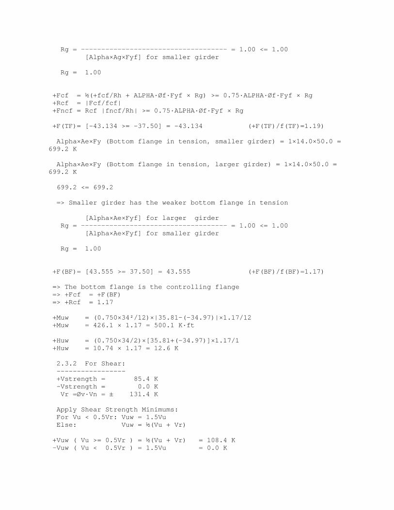
Rg = 1.00
+Fcf = ½(+fcf/Rh + ALPHA·Øf·Fyf × Rg) >= 0.75·ALPHA·Øf·Fyf × Rg+Rcf = |Fcf/fcf|+Fncf = Rcf |fncf/Rh| >= 0.75·ALPHA·Øf·Fyf × Rg
+F(TF)= [-43.134 >= -37.50] = -43.134 (+F(TF)/f(TF)=1.19)
Alpha×Ae×Fy (Bottom flange in tension, smaller girder) = 1×14.0×50.0 =699.2 K
Alpha×Ae×Fy (Bottom flange in tension, larger girder) = 1×14.0×50.0 =699.2 K
699.2 <= 699.2
=> Smaller girder has the weaker bottom flange in tension
[Alpha×Ae×Fyf] for larger girderRg = ------------------------------------ = 1.00 <= 1.00
[Alpha×Ae×Fyf] for smaller girder
Rg = 1.00
+F(BF)= [43.555 >= 37.50] = 43.555 (+F(BF)/f(BF)=1.17)
=> The bottom flange is the controlling flange=> +Fcf = +F(BF)=> +Rcf = 1.17
+Muw = (0.750×34²/12)×|35.81-(-34.97)|×1.17/12+Muw = 426.1 × 1.17 = 500.1 K·ft
+Huw = (0.750×34/2)×[35.81+(-34.97)]×1.17/1+Huw = 10.74 × 1.17 = 12.6 K
2.3.2 For Shear:-----------------+Vstrength = 85.4 K-Vstrength = 0.0 KVr =Øv·Vn = ± 131.4 K
Apply Shear Strength Minimums:For Vu < 0.5Vr: Vuw = 1.5VuElse: Vuw = ½(Vu + Vr)
+Vuw ( Vu >= 0.5Vr ) = ½(Vu + Vr) = 108.4 K-Vuw ( Vu < 0.5Vr ) = 1.5Vu = 0.0 K

2.3.3 Design Forces:---------------------Pu (TF) =-43.1 × 15.1Pu (TF) = -652.1 K (compression)
Pu (BF) =43.6 × 14.Pu (BF) = 609.1 K (tension)
Vuw = 108.4 KMuw = 500.1 K·ftHuw = 12.6 K
2.4 Service Limit State (AASHTO 3.4.1):________________________________________
2.4.1 For POSITIVE Moment:---------------------------
**POSITIVE STRESS DISTRIBUTION**STRESS TOP OF STEEL TOP OF WEB BOT OF WEB BOT OF
STEELCOMPONENT (K/in²) (K/in²) (K/in²) (K/in²)f(DC1): -23.91 -22.27 22.27 23.91f(DC2): -1.14 -1.04 1.60 1.70f(DW): 0.00 0.00 0.00 0.00f(+LL+I): -0.52 -0.45 1.30 1.37+Ffactored: -25.72 -23.90 25.56 27.38
=> +Average: +fTF : -24.81 +fBF : 26.47
+Mser (web) = (0.750×34²/12)×|-23.90-(25.56)|/12+Mser (web) = 297.8 K·ft
+Hser (web) = (0.750×34/2)×[-23.90+(25.56)]/1+Hser (web) = 21.2 K
2.4.2 For Shear:-----------------+Vservice = 62.1 K-Vservice = 0.0 K
2.4.3 Design Forces:---------------------Pser (TF) = -375.1 K (compression)Pser (BF) = 400.2 K (tension)Vser (Web) = 62.1 KMser (Web) = 297.8 K·ftHser (Web) = 21.2 K
3. SUMMARY OF AASHTO SPLICE DESIGN FORCES:===========================================

DESIGN LOAD/LIMIT STATE: CONSTRUCTION FATIGUE SERVICESTRENGTH
Top Splice Force ( K) -460.7 0.0 -375.1 -652.1
Bottom Splice Force ( K) 460.7 4.5 400.2609.1
Web Splice Shear ( K) 69.4 0.9 62.1108.4
Web Splice Moment ( K·ft) 353.9 2.4 297.8500.1
Web Splice Horizontal( K) 0.0 2.4 21.212.6
4. SPLICE ANALYSIS:====================
4.1 Top Flange Splice Analysis:________________________________
4.1.1 Plate Analysis:----------------------
Maximum Inner/Outer Plate Area Variation:Maximum Req'd Area Percentage = 10.0% >= 90.5% *NO*=> Total forces are therefore divided 34.4% and 65.6% between the
Innerand Outer Splice Plates, respectively.
The Strength Limit State / During Construction:
Yielding of the Gross Section:
Compression Agreq(Inner Splice)=|-224.5|/(50×0.90)= 4.99 in²Compression Agreq(Outer Splice)=|-427.6|/(50×0.90)= 9.5 in²
The Fatigue Limit State (Inner and Outer Splices):Agreq (Inner Splice) = 0.0 / 16 = 0.0 in²Agreq (Outer Splice) = 0.0 / 16 = 0.0 in²
The Service Limit State:Prevention of Permanent Deflection (Inner Splice):
Agreq (+M) = |-129.1| / (50×0.95) = 2.72 in²
Prevention of Permanent Deflection (Outer Splice):Agreq (+M) = |-245.9| / (50×0.95) = 5.18 in²
Summary:
Criterion Req'd Gross Area(in²) Req'd Net Area(in²)
INNER SPLICE PLATESGross Yielding 4.99 NAFatigue 0.0 NA

Permanent Deflection 2.72 NAControlling Values = 4.99 NAActual Inner Splice Area = 5.25 *OK* NA *OK*
OUTER SPLICE PLATEGross Yielding 9.5 NAFatigue 0.0 NAPermanent Deflection 5.18 NAControlling Values = 9.5 NAActual Outer Splice Area = 10.0 *OK* NA *OK*
4.1.2 Bolt Analysis:---------------------
Check 10 rows of 2 bolts @ 3 in pitch (Total Bolts = 20)
Plate Slip Resistance:Single Slip Plane = 390.0 => 0.66Max(|Pser|,|Pcon|) = |-302.1| K
*OK*
Bolt Shear Requirement:Single Shear Plane = 554.2 => 0.66Pu = |-427.6| K *OK*
Plate Bearing Requirement:
Inner Splice (C) = 1,638.0 => 0.34Pu = |-224.5| K *OK*Outer Splice (C) = 2,184.0 => 0.66Pu = |-427.6| K *OK*Girder Flange(C) = 2,730.0 => 1.00Pu = |-652.1| K *OK*
Minimum Bolt Rows Requirement:Default Minimum Value Specified = 2 rows <= 10 rows *OK*
4.1.3 Spacing Limit Analysis:------------------------------
All Pitch, Gage, Edge and End Distance values are in accordancewith
AASHTO Art. 6.13.2.6.
4.2 Bottom Flange Splice Analysis:___________________________________
4.2.1 Plate Analysis:----------------------
Maximum Inner/Outer Plate Area Variation:Maximum Req'd Area Percentage = 10.0% >= 90.5% *NO*=> Total forces are therefore divided 34.4% and 65.6% between the
Innerand Outer Splice Plates, respectively.
The Strength Limit State / During Construction:
Yielding of the Gross Section:

Tension Agreq (Inner Splice) = 209.7 / (50×0.95) = 4.41 in²Tension Agreq (Outer Splice) = 399.4 / (50×0.95) = 8.41 in²
Fracture of the Net Section:Tension Anreq (Inner Splice) = 209.7 / (65×0.80) = 4.03 in²Tension Anreq (Outer Splice) = 399.4 / (65×0.80) = 7.68 in²
The Fatigue Limit State (Inner and Outer Splices):Agreq (Inner Splice) = 1.6 / 16 = 0.1 in²Agreq (Outer Splice) = 3.0 / 16 = 0.19 in²
The Service Limit State:Prevention of Permanent Deflection (Inner Splice):
Agreq (+M) = |137.8| / (50×0.95) = 2.9 in²
Prevention of Permanent Deflection (Outer Splice):Agreq (+M) = |262.4| / (50×0.95) = 5.52 in²
Summary:
Criterion Req'd Gross Area(in²) Req'd Net Area(in²)
INNER SPLICE PLATESGross Yielding 4.41 NANet Fracture NA 4.03Fatigue 0.1 NAPermanent Deflection 2.9 NAControlling Values = 4.41 4.03Actual Inner Splice Area = 5.25 *OK* 3.84 *NG*
OUTER SPLICE PLATEGross Yielding 8.41 NANet Fracture NA 7.68Fatigue 0.19 NAPermanent Deflection 5.52 NAControlling Values = 8.41 7.68Actual Outer Splice Area = 10.0 *OK* 8.13 *OK*
4.2.2 Bolt Analysis:---------------------
Check 10 rows of 2 bolts @ 3 in pitch (Total Bolts = 20)
Plate Slip Resistance:Single Slip Plane = 390.0 => 0.66Max(|Pser|,|Pcon|) = 302.1 K
*OK*
Bolt Shear Requirement:Single Shear Plane = 554.2 => 0.66Pu = 399.4 K *OK*
Plate Bearing Requirement:

Inner Splice (T) = 1,570.7 => 0.34Pu = 209.7 K *OK*Outer Splice (T) = 2,094.3 => 0.66Pu = 399.4 K *OK*Girder Flange(T) = 2,730.0 => 1.00Pu = 609.1 K *OK*
Minimum Bolt Rows Requirement:Default Minimum Value Specified = 2 rows <= 10 rows *OK*
4.2.3 Spacing Limit Analysis:------------------------------
All Pitch, Gage, Edge and End Distance values are in accordancewith
AASHTO Art. 6.13.2.6.
4.2.4 Block Shear Rupture Analysis:------------------------------------
Outer Splice Factored Design Load (0.66Pu(B)) = 399.4 K *OK*Outer Splice Plate Resistance (Path 1) = 959.8 K
Inner Splice Factored Design Load (0.34Pu(B)) = 209.7 K *OK*Inner Splice Plate Resistance (Path 4) = 986.4 K
Girder Flange Factored Design Load (1.0Pu(B)) = 609.1 K *OK*RightGirder Flange Resistance (Path 7) = 1,853.6 K
4.3 Web Splice Analysis:_________________________
4.3.1 Bolt Analysis:---------------------
Minimum Bolt Rows Requirement:Default Minimum Value Specified = 2 rows <= 3 rows *OK*
Minimum Bolts/Row Requirement:Minimum Bolts @ Maximum Spacing = 5 bolts <= 10 *OK*
Plate Slip Requirement:
Slip Resistance/Bolt = 39.0 K/bolt
During Construction: Crequired = 1.78e = 66.5344 in
Theta = 0.0°Cprovided = 2.56 *OK*
Service Limit State: Crequired = 1.59e = 62.876 in
Theta = 18.8°Cprovided = 2.63 *OK*
Bolt Shear Requirement:

Shear Resistance/Bolt = 55.4 K/bolt
Strength Limit State: Crequired = 1.96e = 60.7095 in
Theta = 6.6°Cprovided = 2.77 *OK*
Plate Bearing Requirement (Left Girder Web):
Strength Limit State: Crequired = 1.32e = 60.7095 in
Theta = 6.6°Cprovided = 2.77 *OK*
Above resistances calculated w/r/to the given splice dimensions of:Number of Bolts/Row = 10 boltsVertical Bolt Spacing = 3 inVertical End Distance = 1.5 inNumber of Bolt Rows = 3 rowsLongitudinal Bolt Spacing = 3 inLongitudinal End Distance = 1.5 inGeometric Eccentricity = 5.3438 inSplice Plate Thickness = 0.75 in
4.3.2 Plate Analysis:----------------------
Shear Analysis:The Strength Limit State / During Construction:
Yielding of the Gross Section:Agreq = |108.4| / (1.00×0.58×50) = 3.74 in²
Fracture of the Net Section:Anreq = |108.4| / (0.80×0.58×65) = 3.59 in²
Summary:Criterion Req'd Gross Area(in²) Req'd Net Area(in²)Gross Yielding 3.74 NANet Fracture NA 3.59Controlling Values = 3.74 3.59Actual Web Splice Area = 45.0 *OK* 30.94 *OK*
Flexural Analysis:Splice Plates' Elastic Section Modulus, Sxx = 225.0in³Web Splice Bolt Group Eccentricity, e = 5.3438 in
During Construction:fm = 20.53 ksifh = 0.00 ksifcon = 20.53 ksi <= 50 ksi *OK*
The Fatigue Limit State:+fm = 0.15 ksi

+fh = 0.05 ksiffat = 0.20 ksi <= 16 ksi *OK*
The Service Limit State:fm = 17.36 ksifh = 0.47 ksifser = 17.83 ksi <= 48 ksi *OK*
The Strength Limit State:fm = 29.25 ksifh = 0.28 ksifstr = 29.53 ksi <= 50 ksi *OK*
4.3.3 Spacing Limit Analysis:------------------------------
All Spacing, Edge, and End Distance values are in accordance withAASHTO Art. 6.13.2.6.
4.3.4 Block Shear Rupture Analysis:------------------------------------
Web Splice Factored Design Load (Vuw) = 108.4 K *OK*Web Splice Resistance (Path 1) = 1,087.5 K
5. SUMMARY:============
PERFORMANCE RATIOS:
Performance Ratios are the ratio of the applied load to the respectivecomponent resistance (i.e., LOAD / RESISTANCE).
TOP FLANGE SPLICE (0.95):
Splice Plates (0.95):Gross Area (Outer Splice) 0.95Gross Area (Inner Splice) 0.95Net Area (Outer Splice) NANet Area (Inner Splice) NA
Connection Bolts (0.77):Bolt Slip 0.77Bolt Shear 0.77Plate Bearing 0.24
BOTTOM FLANGE SPLICE (1.05):
Splice Plates (1.05):Gross Area (Outer Splice) 0.84Gross Area (Inner Splice) 0.84Net Area (Outer Splice) 0.95Net Area (Inner Splice) 1.05

Connection Bolts (0.77):Bolt Slip 0.77Bolt Shear 0.72Plate Bearing 0.22
Block Shear 0.42
WEB SPLICE (0.71):
Connection Bolts (0.71):Bolt Slip - Construction 0.70Bolt Slip - Service 0.61Bolt Shear - Strength 0.71Plate Bearing - Strength 0.48
Splice Plates (0.59):Shear Yield - Strength 0.08Shear Fracture - Strength 0.12Flexure - Construction 0.41Flexure - Fatigue 0.01Flexure - Service 0.38Flexure - Strength 0.59
Block Shear 0.10
