fundamental safety requirements for nuclear power plants ... · 3 beilage ilk-31 4 preamble (0)...
TRANSCRIPT
Fundamental Safety Requirements for Nuclear Power Plants(Attachment to ILK-31)
Auch deutsche Fassung verfügbar
September 2008

1
Beilage ILK-31
2
CONTENT Preamble .............................................................................................. 3
1 Safety principles ................................................................................... 5
2 Design requirements (Levels of defense 1–3) ......................................... 9
2.1 Defense-in-depth safety concept and safety goals .................................. 9
2.2 Barriers .............................................................................................. 10
2.3 Principles promoting safety ................................................................. 11
2.4 Representative range of events ............................................................ 13
2.5 Requirements on safety functions ........................................................ 14
2.5.1 Safety goal: “Reactivity control” ........................................................... 15
2.5.2 Safety goal: “Cooling of fuel elements” ................................................ 17
2.5.3 Safety goal: “Activity retention” ........................................................... 21
2.6 System requirements on containment system ....................................... 22
2.7 Requirements on systems with cross-functionality ................................ 23
2.8 Handling and storage of fuel elements and other radioactive
substances ......................................................................................... 26
2.9 General impacts .................................................................................. 26
2.10 Safety related classification of structures, systems and components ..... 27
3 Risk reduction (Level of defense 4) ...................................................... 28
3.1 Basics ................................................................................................ 28
3.2 Sub-level 4a ....................................................................................... 29
3.3 Sub-levels 4b and 4c .......................................................................... 29
4 Deterministic and probabilistic safety analyses ..................................... 30
4.1 Verification of safety ........................................................................... 30
4.2 Deterministic safety analysis ............................................................... 31
4.3 Probabilistic safety analysis................................................................. 33
5 Safety reviews .................................................................................... 34

1 2
Beilage ILK-31
6 Organization of nuclear power plant operation ...................................... 35
6.1 Corporate safety policy ........................................................................ 35
6.2 Organization of the licensee ................................................................ 36
6.3 Training and authorizations of operating staff ....................................... 36
6.4 Integrated management system ........................................................... 37
6.5 Plant modifications ............................................................................. 38
6.6 Maintenance ....................................................................................... 39
6.7 On-site emergency preparedness ......................................................... 39
7 Safety documentation ......................................................................... 41
7.1 Instructions for accident management and on-site emergency
protection ........................................................................................... 42
7.2 Limit values and conditions for safe operation ...................................... 43
8 Investigation of special incidents and experience feedback ................... 44
Annex 1: Safety goals, safety sub-goals and safety functions ........................... 45
Annex 2: Initiating events to be taken into account .......................................... 47
Annex 3: VO events ........................................................................................ 50
Annex 4: Specific very rare events .................................................................. 53
List of abbreviations ...................................................................................... 54
References .................................................................................................... 55
3
Beilage ILK-31
4
Preamble(0) These fundamental safety requirements are directed at the operating nuclear
power plants in Germany. They also include requirements related to design and construction, however, with a limited application range since according to § 7 para 1 sentence 2 of the Atomic Energy Act (AtG, “Atomgesetz”) no further licenses will be issued for the construction and operation of new nuclear power plants. Therefore, these requirements mainly apply to backfits, assess-ments within the framework of safety reviews, plant or operational modifica-tions, assessment of notifiable events, reviews regarding information notices as well as safety verifications regarding accident control due to new insights.
(1) The Atomic Energy Act states that the protection of life, health and property from the hazards of nuclear energy and the detrimental effects of ionizing radiation has to be ensured in the peaceful utilization of nuclear power. The evidence of the necessary precautions against damage according to the sta-te-of-the-art in science and technology was mandatory for granting licenses for the construction and operation of German nuclear power plants.
(2) The requirements for protecting man and the environment from radioactive substances or ionizing radiation when carrying out goal-oriented activities in the utilization of nuclear power are laid down in the Radiation Protection Ordinance (“Strahlenschutzverordnung”). Accordingly, these activities must correspond to the principles of radiation protection regarding their justificati-on, dose limitations as well as the avoidance of unnecessary radiation expos-ure and dose reduction.
(3) The present fundamental safety requirements describe the basic technical and organizational provisions that are to be met by existing nuclear power plants with light water reactors to ensure the precaution against damage required by § 7 para. 2 no. 3 Atomic Energy Act and in particular to comply with the principles and requirements laid out in the Radiation Protection Ordinance. In addition, the fundamental safety requirements cover principles for dealing with beyond design basis events and plant states.
(4) The fundamental safety requirements in particular aim to cover the following guidelines and regulations:
the BMI Safety Criteria (“BMI-Sicherheitskriterien”) and Accident •Management Guidelines (“Störfall-Richtlinien”) insofar as these documents are to be considered as fundamental requirements in terms of their level of detail
the essential contents of the WENRA reference levels. •
3 4
Beilage ILK-31
(5) In terms of its level of detail, these fundamental safety requirements should be viewed as a framework for the technical set of regulations. Regarding its content and the overall hierarchy, it sits between the more general require-ments of the Atomic Energy Act and the Radiation Protection Ordinance on the one hand and the entirety of more detailed requirements such as those given in the KTA technical guidelines on the other. It is the objective to put the general legal nuclear and radiation protection requirements into concrete terms and to consolidate the fundamental non-legislative requirements of the safety criteria, the accident management guidelines and the RSK guidelines. Thus, all important safety-related topics are addressed at least briefly, even if these are already sufficiently regulated at a comparable level of detail in the set of guidelines currently in force.
5
Beilage ILK-31
6
1 Safety principles(1) The safe operation of a nuclear power plant calls for a holistic approach
incorporating the impact of man, technology and organization on safety. This approach has to cover the following basic elements:
A plant design based on tried and tested technology that counters the •hazard potential of radioactive materials contained in nuclear power plants by applying an effective and reliable defense-in-depth concept,
safety verifications that ensure compliance with requirements placed on •safety design with high certainty,
systematic organizational measures, which are related to staff qualification •as well as ergonomic provisions1 for achieving a safety-oriented interaction between man and technology.
(2) The responsibility for ensuring safety lies with the licensee2 of the nuclear power plant. Due to this responsibility the licensee has to ensure that questi-ons of safety are given priority in all operating activities. The federal and state authorities which are responsible for the execution of the Atomic Energy Act should pursue their tasks in such a way that the licensee is strengthened in the pursuit of this task in his own responsibility.
(3) Radioactive materials in the reactor and in stored irradiated fuel elements have to be safely confined by several barriers. The required number and design of these barriers are based on the hazard potential of the confined radioactive material and on their potential release.
(4) To protect the function of the barriers, a defense-in-depth safety concept is to be applied that primarily ensures reliable damage prevention and furthermore contains graduated provisions for controlling damage incidents or for limiting damage impact.
The defense-in-depth safety concept for nuclear power plants encompasses four levels of defense, where the fourth level of defense is subdivided into
1 Within this document, the term “provision” is used if a combination of measures and technical installations or technical solutions is concerned or if an alternative application of measures or technical installations or solutions is considered.
2 The licensee is the party that possesses a license to operate a nuclear power plant and is named as the owner of the plant in the license. If there are several holders of the operating license then the licensee is the one that exercises the actual control of the operated plant and bears the com-mercial risk.
5 6
Beilage ILK-31
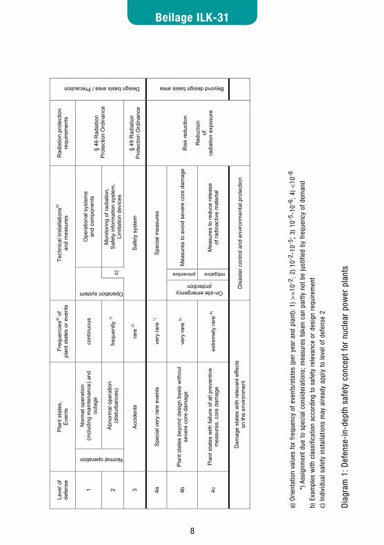
three sub-levels (diagram 1). The levels of defense are defined by event clas-ses3 which are formed under consideration of the frequency of events and plant states and cover those plant states from normal operation up to extre-mely unlikely situations which can reasonably be expected.
Technical goals and acceptance criteria for safety verifications are assigned to these event classes.
(5) The following safety goals shall be achieved with the support of the provisions taken within the framework of the defense-in-depth concept:
Control of reactivity, •
Cooling of fuel elements •
Activity retention. •
For this purpose, nuclear power plants must have safety functions; their effec-tiveness and reliability is specified in the principles stated in 1(4).
(6) The levels of defense 1 – 3 define the design basis. For this area, the following criteria are to be applied regarding dimensioning of effectiveness and reliabi-lity of the safety functions:
the requirements of the Radiation Protection Ordinance must be complied •with for all events and plant states.
A progression from events or plant states towards the superseding event •class has be prevented.
A progression towards a beyond design basis plant state • 4 must be practi-cally eliminated5.
(7) Level of defense 4 defines the beyond design basis area. Those events and plant states are assigned to this level that can be practically excluded due to their extremely low probability of occurrence or due to the precaution against damage taken on levels of defense 1 to 3.
The corresponding measures aim at a reduction of the remaining risks. The measures are divided into measures for protection against special very rare events (sub-level 4a) and into measures of on-site emergency preparedness
3 The term "event class" is used here for events in their original meaning (in particular those events listed in Annex 2 -4) but also for classes of plant states (e.g. normal operation or plant states beyond design basis).
4 Plant states which belong to level of defense 4
5 By this means the required precaution according to the state-of-the-art in science and technology for levels of defense 1-3 is taken.
7
Beilage ILK-31
8
(sub-level 4b and 4c).
(8) The defense-in-depth concept of safety for nuclear power plants should follow a well-balanced concept. In particular, measures and installations provided to ensure safety shall correspond to the risks they are intended to counteract. As far as this is practicable, the basic principle that more frequent events are handled with larger safety margins6 than rare events and that events with potentially more serious consequences must show a correspondingly lower probability of occurrence shall be applied.
(9) The requirements outlined in the following chapters give substance to the safety principles formulated in the paragraphs (1) to (8). In some cases, these substantiated requirements may not or may not fully be applicable to existing constructive realizations in the area of design and construction. Given such a case, other measures are permissible, as long as these ensure an equivalent level of safety when taking operating experience and proven operating record into account.
6 "Safety margins" here refer to integral reserves consisting of safety factors and other conservative assumptions as well as the potential due to measures, which are still available for control of the specific situation
7 8
Beilage ILK-31IL
K: F
unda
men
tal S
afet
y R
equi
rem
ents
for N
ucle
ar P
ower
Pla
nts
- Sep
tem
ber 2
008
(Atta
chm
ent t
o IL
K-3
1)
6
a) O
rient
atio
n va
lues
for f
requ
ency
of e
vent
s/st
ates
(per
yea
r and
pla
nt):
1) ≥
10−2
, 2)
10−2
− 1
0−5,
3) 1
0−5 −
10−6
, 4)
< 1
0−6
*)
Ass
ignm
ent d
ue to
spe
cial
con
side
ratio
ns; m
easu
res
take
n ca
n pa
rtly
not b
e ju
stifi
ed b
y fre
quen
cy o
f dem
and
b) E
xam
ples
with
cla
ssifi
catio
n ac
cord
ing
to s
afet
y re
leva
nce
or d
esig
n re
quire
men
t c)
Indi
vidu
al s
afet
y in
stal
latio
ns m
ay a
lread
y be
app
ly to
leve
l of d
efen
se 2
Dia
gram
1: D
efen
se-in
-dep
th s
afet
y co
ncep
t for
nuc
lear
pow
er p
lant
s
Leve
l of
defe
nse
Pla
nt s
tate
s,
Eve
nts
Freq
uenc
iesa)
of
plan
t sta
tes
or e
vent
s Te
chni
cal i
nsta
llatio
nsb)
and
mea
sure
s R
adia
tion
prot
ectio
n re
quire
men
ts
1N
orm
al o
pera
tion
(incl
udin
g m
aint
enan
ce) a
nd
outa
ge
cont
inuo
us
Ope
ratio
nal s
yste
ms
and
com
pone
nts
2
Normal operation
Abno
rmal
ope
ratio
n (d
istu
rban
ces)
fre
quen
tly 1)
Operation system
c)
Mon
itorin
g of
radi
atio
n,
Saf
ety
info
rmat
ion
syst
em,
Lim
itatio
n de
vice
s
§ 46
Rad
iatio
n P
rote
ctio
n O
rdin
ance
3 A
ccid
ents
ra
re 2)
S
afet
y sy
stem
§
49 R
adia
tion
Pr
otec
tion
Ord
inan
ce
Design basis area / Precaution
4a
Spe
cial
ver
y ra
re e
vent
s ve
ry ra
re *)
Sp
ecia
l mea
sure
s
4bP
lant
sta
tes
beyo
nd d
esig
n ba
sis
with
out
seve
re c
ore
dam
age
very
rare
3)
preventive
Mea
sure
s to
avo
id s
ever
e co
re d
amag
e
4cP
lant
sta
tes
with
failu
re o
f all
prev
entiv
e m
easu
res,
cor
e da
mag
e ex
trem
ely
rare
4)
On-site emergency protection
mitigative
Mea
sure
s to
redu
ce re
leas
e of
radi
oact
ive
mat
eria
l
Beyond design basis area
Dam
age
stat
es w
ith re
leva
nt e
ffect
s on
the
envi
ronm
ent
Dis
aste
r con
trol a
nd e
nviro
nmen
tal p
rote
ctio
n
Ris
k re
duct
ion
Red
uctio
n of
radi
atio
n ex
posu
re
a) O
rient
atio
n va
lues
for
fre
quen
cy o
f ev
ents
/sta
tes
(per
yea
r an
d pl
ant):
1) >
=10
-2; 2
) 10-
2 -10
-5; 3
) 10-
5 -10
-6; 4
) <10
-6
*)
Ass
ignm
ent
due
to s
peci
al c
onsi
dera
tions
; mea
sure
s ta
ken
can
part
ly n
ot b
e ju
stifi
ed b
y fr
eque
ncy
of d
eman
d
b) E
xam
ples
with
cla
ssifi
catio
n ac
cord
ing
to s
afet
y re
leva
nce
or d
esig
n re
quire
men
t
c) In
divi
dual
saf
ety
inst
alla
tions
may
alre
ady
appl
y to
leve
l of
defe
nse
2
Dia
gram
1: D
efen
se-i
n-de
pth
safe
ty c
once
pt f
or n
ucle
ar p
ower
pla
nts
9
Beilage ILK-31
10
2 Design requirements (Levels of defense 1–3)
2.1 Defense-in-depth safety concept and safety goals(1) In nuclear power plants, a defense-in-depth safety concept with the following
basic elements is to be applied:
Barriers for the effective confinement of radioactive material in the reactor •and in the stored radiated fuel elements, whose number and design is determined following the principles stated in paragraphs 1(3) and 1(8),
Graduated provisions to prevent, as far as possible, damage to the barriers •during normal operation or during accidents and to control the course of events without impermissible impairment to the confinement of radioactive material in those cases where a partial or complete loss of barrier function occurs.
Accompanying provisions for minimization of radiation exposure, i.e. the •controlled limitation or reduction of radioactive releases, permanent and temporary shielding to protect against direct radiation, measures for avoi-ding contamination as well as provisions for sampling and for monitoring of radiation protection.
(2) It has to be ensured that the safety goals stated in paragraph 1(5) - reactivity control, cooling of fuel elements and activity retention - are attained during normal operation as well as during accidents.
(3) If the attainment of safety goals can not already be ensured by basic and unchangeable design attributes of the specific reactor construction line, the nuclear power plants have to provide specific safety functions. Annex 1 lists those safety functions which have to be implemented in German nuclear power plants with pressure water reactors or boiling water reactors in order to attain the safety goals during events or accidents. The fundamental requirements for these functions are covered in chapter 2.5.
(4) The stipulations of the Radiation Protection Ordinance are decisive for the assessment of the compliance of the safety goal “activity retention” and the accompanying provisions for minimization of radiation exposure. The corre-sponding requirements on safety functions, as stated in chapter 2.5, serve to put this minimization principle into concrete terms.
9 10
Beilage ILK-31
2.2 Barriers(5) Barriers for the effective confinement of radioactive materials within the reac-
tor are:
the fuel matrix and the fuel rod claddings •
the pressure retaining boundary of the reactor coolant •
the containment system • 7.
(6) The effectiveness of installations and system functions for supporting the barrier containment functions are to be viewed as part of the barrier function. Such installations and functions in particular include:
Retaining of radio nuclides in solid materials (e.g. ceramics), •
Graduated negative pressure and corresponding retaining installations, •
Separation of activity-carrying systems from those not carrying activity, •
Water cover for shutdown operation with open primary circuit and for sto- •rage of fuel elements in the fuel pool,
Protective effect of the reactor building and other structures against airbor- •ne or fluid releases.
(7) In the event that individual barriers are opened or are not available during operational procedures, the safe confinement of radioactive materials must be guaranteed using the remaining barriers and further retaining functions and, if this is not sufficient, by additional supporting provisions.
(8) The barriers must be independent of each other to such a degree that during accidents employing safety functions which are as effective as designed one barrier does not fail as the result of the failure of another barrier.
In the case of accidents with ruptures in the pressure retaining boundary, a failure of the fuel rod cladding is permissible as long as the accident limit values of § 49 of the Radiation Protection Ordinance are not exceeded.
Technical criteria must be defined for the barriers so that compliance with these criteria ensures integrity of the barrier that is appropriate to the level of defense in question.
7 The containment system includes the containment as a component as well as safety functions for its isolation if needed.

11
Beilage ILK-31
12
2.3 Principles promoting safety(9) Principles that promote safety in design, manufacturing and operation are to
be applied, such as in particular
an extensive quality assurance, •
safety margins in the design of structures, systems and components, •
use of tested materials, •
ergonomic measures at the work places, •
safe monitoring of operating conditions, •
execution of in-service inspections with an appropriate scope, •
ease of maintenance especially considering the radiation exposure of •staff.
(10) The construction of pressure retaining components with special significance for reactor safety or whose failure can lead to severe on-site damage8 must be optimized in terms of function, load, material, production (manufacture and testing) and maintenance.
(11) The pressure retaining boundary9 of the primary reactor coolant has to able to take up10 all loads resulting from operation and from accidents during the whole lifetime of the plant. This has to be verified taking into consideration
the basic safety of components based on •
8 These components include the components of the pressure retaining boundary of the primary cooling circuit - including the secondary-side shell of the steam generator for PWR – as well pres-surized claddings of other pressure and activity retaining systems and components which have a specific safety relevance (“outer systems”) because they are required e.g. for shutdown, maintai-ning long-term subcriticality and imminent residual heat removal in case of accidents or because their failure may lead to the release of high energies, the impairment of functions of safety instal-lations or massive damages within the plant.
9 For PWR, it is especially the reactor pressure vessel, those parts of the steam generator containing primary coolant, the pressurizer, the reactor coolant pump casing, connecting pipes as well as transfer pipes with greater nominal widths up to the first isolation valve as well as integral areas of component support structures which belong to the pressure retaining boundary. The secondary-side shell of the steam generator is to be dealt with in the same manner as the pressure retaining boundary regarding material selection, design principles, quality assurance, manufacturing inspec-tion and in-service inspection.
For BWR, it is especially the reactor pressure vessel, pipes up to the first isolation valve which belong to the same pressure area as the reactor pressure vessel, pipes penetrating the contain-ment up to the first isolation valve outside the containment, pressurized claddings of the control rod drives, core instrumentation and the forced circulation pumps as well as integral component support structures which belong to the pressure retaining boundary.
10 Ruptures of the pressure retaining boundary for which accident analyses have to be carried out have to be postulated according to these verifications.
11 12
Beilage ILK-31
high-quality material properties, particularly with regard to toughness -
conservative limitation of primary strains -
avoidance of peak stresses through optimal construction -
ensuring the application of optimal manufacturing and testing technolo- -gies
knowledge and assessment of any existing fault conditions -
consideration of the operating medium. -
relevant conditions during operation, e.g. loads, monitoring •
Postulates regarding ruptures of the pressure retaining boundary, for which accident analyses have to be carried out, have to be defined taking into con-siderations these verifications.
If the requirements for basic safety can not be complied with completely, compensatory measures have to be taken according to the framework speci-fication “Basissicherheit von druckführenden Komponenten” [RSK-1979, “basic safety of pressure retaining components”].
(12) Apart from the operating system and individual safety installations, in parti-cular limiting instrumentation and control devices are installed for controlling anomalous operating conditions (disturbances) (see Diagram 1). These devi-ces are to be designed in such a way that a progression from disturbances to accidents is reliably prevented and that their postulated failure does not lead to an impaired function of safety-related systems.
(13) For ensuring a high reliability of installations for controlling accidents, the following basic principles are to be applied in their design:
use of qualified components with proven operating record or similar expe- •rimental qualification,
availability of safety functions even if a random single failure or an appro- •priate combination11 of single failure and maintenance is assumed,
availability of safety functions even for loss of station service power supp- •ly from the plant generator and off-site power supply,
accident resistance, •
testability, •
11 Postulate of maintenance case according to interpretations of the safety criteria for nuclear power plants: single failure concept [SiKri-Einzelfehler]
13
Beilage ILK-31
14
extensive automatic or passive activation so that operator actions are not •required within 30 minutes after event initiation and display or notification in the control room,
priority of measures for the control of accidents over actions of operating •installations,
prevention of damages across redundancies, •
assumption of consequential damages for the assessment of system effec- •tiveness,
consideration of safety-enhancing effects is limited to safety installations. •
Additional principles which increase reliability are applied within the frame-work of deterministic safety analyses (cf. chapter 4.2).
(14) As far as this is appropriate and practicable for the optimization of the relia-bility of the safety installations, the following principles are to be applied as well during their design:
application of acknowledged principles to avoid cross-redundancy failures, •including especially diversity, extensive decoupling of sub-systems and spatial separation of redundant sub-systems,
inherent properties of the plant, •
safety-oriented properties in case of malfunctions of sub-systems or plant •sections (fail-safe-principle),
preference of passive compared to active safety functions if this serves to •achieve a higher reliability, less susceptibility to disturbances or a reduction of radiation exposure.
(15) The safety tasks of all structures, systems and components as well as their corresponding quality requirements determined by their safety significance must be clearly defined and documented.
2.4 Representative range of events(16) For every plant, a compilation of representative on-site events as well as
natural and human-induced external events is to be determined which have to covered within the framework of safety reviews and – as far as they are relevant – of licensing procedures. These representative events have to cover all events that can be assigned, on the basis of their probability of occurrence
13 14
Beilage ILK-31
(see Diagram 1), to levels of defense 2 and 3 with potential hazards to the safety goals.
As a general principle
at least the events listed in Annexes 2 and 3 should be considered during •the selection of representative events,
the representative events should be assigned to the event classes and •levels of defense according to Annex 2
Deviations in the selection and assignment of events have to be justified and the relevance of events which are not covered has to be explained, if neces-sary.
(17) The assignment of events to event classes according to Annex 2 with the frequency ranges according to Diagram 1 shall be verified in appropriate intervals regarding its consistency.
(18) As a basic principle, accident analyses must be prepared for all representati-ve events, in order to demonstrate that the safety goals are achieved and that the requirements of the Radiation Protection Ordinance are met. For the events listed in Annex 3 such analyses are not required if precautionary measures12 are taken to avoid this event or to control it without radiological consequences. The effectiveness and reliability has to be verified, if applicab-le with support by a PSA. Appropriate precautionary measures are listed in Annex 3 as well.
2.5 Requirements on safety functions(19) In principle, the safety functions which have to be attained according to para-
graphs 1(5) and 2(3) can be implemented in different ways by design charac-teristics, inherent properties or by passive or active provisions. The following requirements apply to the design concepts existing in German plants.
(20) Annex 1 lists the set of safety functions for German nuclear power plants and their assignments to safety sub-goals13 which forms the basis for this docu-
12 These events are also described with the abbreviation "VO", following the Accident Management Guidelines (“Störfall-Leitlinien”).
13 There are differences in the literature and in practice for the concrete definition of safety functions and especially for their assignment to safety sub-goals. The definitions and assignments used in this chapter and in the annex are based upon the practice of recent safety reviews of German nuclear power plants. They are based on the assumption, that properties of the physical barriers (e.g. the integrity of fuel rod claddings) as well as provisions against general impacts and long-term effects are not assigned to the safety function. Instead, they are covered separately.

15
Beilage ILK-31
16
ment. Following, the essential non design specific requirements on safety functions are described as far as they are important in order to attain the safety goals for individual internal events at level of defense 2 and 3.
These requirements are structured according to safety sub-goals. Safety functions, which are required for the attainment of several safety sub-goals are stated explicitly only for one safety sub-goal while other safety sub-goals contain a reference. Safety functions applying to all safety goals are covered separately.
2.5.1 Safety goal: “Reactivity control”Safety sub-goal: Control of changes of reactivity and power in the reactor core
Safety function: Inherent self-stabilization
(21) The reactor core is to be designed in such a manner that, in addition to the negative reactivity coefficient of the fuel temperature, during nominal opera-tional status and for temperatures above nominal temperatures the reactivity coefficient of the coolant temperature is negative as well and that a potential reduction of the coolant density due to a pressure decrease causes a negati-ve feedback on reactivity and reactor power.
In principle, these requirements have to be satisfied also for plant states below the nominal temperature. If this is temporarily not practicable during begin of a cycle with regard to coolant temperature and coolant density feed-back it has to be verified that the resulting additional power does not lead to a violation of acceptance criteria during accidents.
Safety function: Limitation of reactivity, power and power density
(22) The devices for the control and shutdown of the reactor must be able to cope with all possible reactivity changes in normal operation or during accidents, so that the respective limit values for the reactor system specified for these plant conditions are not exceeded. The physical effectiveness and travel speed of both individual and collectively traveling control rods, as well as any other reactivity control devices14, are to be limited in a manner that also in the case of an erroneous travel command, the specified limit values for the reactor system are complied with.
14 I. e. the circulation pumps for BWR

15 16
Beilage ILK-31
(23) Reactivity steps, which are technically possible, have to be limited in such a manner, that it can be ruled out that specified limit values for criticality and integrity of the fuel elements are exceeded, taking into account counter-measures which may have been applied.
Safety sub-goal: Sustainable termination of the chain reaction within the core
Safety function: Reactor trip
(24) The reactor must possess shutdown devices which are capable to bring the reactor to a sub-critical state from all plant states of specified operation and during accidents and keep it sub-critical.
(25) For all incidents and accidents at least one shutdown device - the reactor trip system - must be capable, if necessary on its own, to bring the reactor to a sub-critical state so quickly that the respective limit values of the reactor system are not exceeded.
(26) At least one shutdown device must be capable to prevent an overstepping of specified limit values of the reactor system even in those cases when the first automatic shutdown initiation fails.
(27) For those accidents which require a reactor trip in order to be managed, the shutdown reactivity resulting must contain an adequate shutdown reserve even if it is assumed as a single failure that the control rod with the highest reactivity effect is not available.
Safety function: Keeping sub-critical state in the long-term
(28) The shutdown devices must be capable to keep the reactor core sub-critical in the long-term15.
(29) As a basic principle an unintentional re-criticality shall not happen after the shutdown. If a temporary re-criticality can not be avoided for certain excep-tional cases, it has to be ensured that the specified limit values for fuel and components are not exceeded.
Safety sub-goal: Control of reactivity of fuel elements outside the reactor core
Safety function: Ensuring subcriticality during handling and transport of fuel elements
(30) A chain reaction in the fuel storage pool or in the storage for new fuel ele-ments is to be excluded during specified operation or accidents16. This requirement shall primarily be met through passive provisions, such as pre-
15 i. e. a cold, xenon-free core
16 Relevant accidents for storage and handling of fuel elements are covered in Annex 2 and 3
17
Beilage ILK-31
18
determined fuel element spacing via storage racks and absorber slots around the fuel elements, integrated neutron absorbers, boration of the pool water. If necessary, these measures can be enhanced by administrative measures, e.g. the prevention of automatic feed-in of deionate.
2.5.2 Safety goal: “Cooling of fuel elements”Safety sub-goal: Heat removal
Safety function: Heat removal from the reactor core
(31) In order to guarantee sufficient integrity of the fuel assemblies, it must be ensured that the heat production and, if necessary, the stored heat, from the reactor core is transferred in such a way that the temperatures of the fuel rod claddings remain within permissible limits. For BWR, this function contains provisions for the automatic pressure relief of the reactor system.
Safety function: Secondary heat removal (PWR)
(32) Following a reactor trip, it must be ensured that the accumulating decay energy and, where necessary, also the stored heat can be transferred via steam release to the main heat sink or to the atmosphere and, if necessary, a sufficiently fast pressure relief can be undertaken, so that the design basis limits of the pressure retaining boundary are not exceeded.
Safety function: Heat removal from the containment17
(33) For accidents with an energy transfer into the containment (PWR) or the dry-well (BWR) the heat is to be transferred in such a way that the pressures and temperatures in the containment or in the drywell stay within specified limits18.
Safety function: Heat removal from the pressure suppression pool (BWR)
(34) The heat removal from the pressure suppression pool must ensure that the temperatures in the pressure suppression pool do not exceed the specified temperature limit values even in case of energy transfer from the reactor system or from the drywell and taking into account the limit of the water temperature.
17 In case of BWR, this refers to the drywell
18 In case of PWR, this includes cooling of the coolant which is drawn from the sump; in case of BWR, this includes the transfer of the discharged steam during a LOCA via the condensation pipes into the pressure suppression pool and potentially also spraying the drywell.

17 18
Beilage ILK-31
(35) In case of a drop of the level due to a leak in the pressure suppression pool provisions have to be taken to secure the heat sink until shutdown cooling is started.
Safety function: Heat removal from fuel storage pool
(36) The heat removal from irradiated fuel elements outside the reactor coolant system is to be ensured.
Safety function: Heat removal via cooling chains19
(37) The heat transfer to the heat sink is to be ensured via cooling chains.
Safety sub-goal: Ensuring the coolant inventory20
Safety function: Replenishing coolant
(38) In the event of a loss of coolant from the pressure retaining boundary, the coolant is to be replenished in such a way that the specified limit values for fuel elements, core internals and for the containment system are not excee-ded.
(39) In case of BWR, the reactor coolant is to be transferred from the drywell back to the pressure suppression pool in such a way, that the required ability for condensation in the pressure suppression pool and the feeding of the reactor pressure vessel from the pressure suppression pool is ensured.
(40) For BWR, the pressure relief of the reactor system is to be considered a part of the coolant replenishing function if the systems for replenishing coolant which have been installed for the fulfillment of the preceding requirements are not capable to feed against all pressures in the reactor system that can occur during the accidents that have to be covered.
Safety function: Reducing loss of coolant
(41) In the event of leaks and larger leakages of coolant retaining pipes outside the containment isolation provisions, e.g. the penetration isolation facility for BWR, are to be applied in order to stop the loss of coolant and to exclude an endangerment of other safety functions due to this loss of coolant. 2.6(73) is to be observed for the implementation.
(42) Rooms which contain systems connected to the pressure retaining boundary are to be provided with leakage detection systems or other comparable instal-
19 The cooling chain encompasses residual heat removal and pool cooling system, component cooling system and auxiliary service water supply.
20 In this document the term „coolant“ stands for the reactor coolant (PWR: primary coolant)
19
Beilage ILK-31
20
lations in order to enable an early detection and isolation of leakages.
(43) In case of BWR, the potential water loss from the pressure suppression pool has to be limited to such an extent21, that the plant will reach a state for which the residual heat removal without use of the pressure suppression pool is ensured before the water level in the pressure suppression pool reaches an unacceptable value.
Safety function: Replenishment of water in the fuel storage pool
(44) In the event of a leak in the fuel storage pool system, a refilling of the pool following isolation and sealing of the leak in the affected train must be pos-sible.
(45) A limited refilling of the pool coupled with a restart of the pool cooling with at least one train must be possible even if the leak has not been sealed. The effectiveness of these provisions has to be such that:
the stored fuel elements are still covered by water, •
no unacceptable pool temperatures are encountered. •
Safety function: Reducing water loss in the fuel storage pool
(46) Pipes leading into the fuel storage pool have to be designed in such a way that in case of a leak or faulty operations in the area of these pipes a level drop is limited to an extent whereby the heat capacity of the remaining water ensures a sufficient time margin for counter measures until the maximum permissible fuel storage pool water temperature is reached.
Safety sub-goal: Ensuring secondary water inventory (PWR)
Safety function: Steam generator feed-in
(47) The feed-in process of steam generators has to ensure that following shut-down the accumulating decay energy and stored heat can be transferred via the steam generators.
Safety function: Reducing the water / steam loss from the secondary cooling circuit
(48) Given a water / steam loss via leakages or via faulty open valves of the secondary cooling circuit of a PWR, these valves are to shut off insofar as this is necessary for ensuring secondary heat removal (e.g. ensuring sufficient feed-in of the steam generators through the emergency cooling system), for
22 e.g. through isolation of pipes in the water area or limitation of leakage rates
19 20
Beilage ILK-31
limiting the loss of coolant in case of steam generator damages or for preven-ting impermissible impacts on other safety functions.
Safety sub-goal: Ensuring the integrity of coolant retaining systems
Safety function: Pressure and temperature limitation in the reactor system
(49) Rises in pressure within the reactor system are to be limited using pressure relief installations of the reactor system or in the case of PWR potentially also by heat transfer to the secondary side to such an extent that the specified limit values for stresses are not exceeded.
(50) Pressures and temperatures must remain within ranges for which a safe margin against brittle fracture of the reactor pressure vessel is given.
(51) Diversity is to be applied for the pressure relief system of BWR.
Safety function: Secondary pressure limitation (PWR)
(52) Rises in pressure within the secondary side cooling circuit are to be limited by pressure relief devices to such an extent that the specified limit values for stresses are not exceeded.
Safety function: Temperature and pressure limitation in the containment
(53) This safety function is covered by heat removal from the containment 2.5(33).
Safety function: Level, pressure and temperature limitation for the pressure suppression pool
(54) Provisions have to be taken to prevent impermissible level, temperature and pressure increases in the pressure suppression pool during specified opera-tion.
(55) Bypasses between drywell and pressure suppression pool which may cause an impermissible pressure transfer to the containment have to be prevented.
(56) The temperature limitation in case of incidents and accidents is covered by 2.5(34).
Safety function: Reactor system overfeed protection
(57) In case of PWR a fill-up of the pressurizer has to be prevented.
(58) An overfeed of the reactor pressure vessel of a BWR has to be excluded through an automatically initiated overfeed protection.
21
Beilage ILK-31
22
Safety function: Steam generator overfeed protection (PWR)
(59) An overfeed of the steam generator of a PWR has to be prevented.
Safety function: Pressure limitation reactor building
(60) Measures have to be taken to prevent an impermissible pressure increase in the reactor building in case of larger leakages in this building.
2.5.3 Safety goal: “Activity retention”(61) The safety goal “activity retention” is closely related to the effectiveness of
the barrier function which in turn is dependent on the integrity of the barriers and the effectiveness of isolation provisions. Since the preservation of the barrier integrity is ensured by the compliance with the other two safety goals or by other requirements, this chapter will only state requirements for isola-tion provisions.
Safety function: Activity confinement pressure retaining boundary
(62) In case of a heating pipe rupture in a PWR an isolation of the corresponding steam generator has to be carried out. The effectiveness of the isolation pro-visions has to be ensured by reduction of the primary pressure.
(63) The additional requirements for this safety function are covered by reducing loss of coolant (2.5(41-43)).
Safety function: Overfill protection
(64) The safety function is covered by reactor system overfeed protection (2.5(55/57-60).
Safety function: Activity confinement containment
(65) For LOCA, a complete isolation of ventilation and an isolation of containment penetrations must be executed.
Safety function: Activity confinement reactor building
(66) For PWR, a possible release of activity during LOCA or through leakages in activity-carrying systems in the annulus is to be minimized by isolating the ventilation of the annulus and by venting the filtered exhaust air through the chimney.
(67) For BWR, the negative pressure system has to be kept even during accidents, as far as possible, in order to minimize releases in case of potential spreading
21 22
Beilage ILK-31
of activity.
Safety function: Activity confinement auxiliary reactor building
(68) An unfiltered exhaust air release is to be prevented during activity releases in the auxiliary reactor buildings.
Safety function: Reduction of activity release via the turbine building (BWR)
(69) With regard to leakages in the turbine building, provisions to reduce activity releases are to be taken for BWR.
2.6 System requirements on containment system(70) The containment system must ensure an effective and reliable retention of
radioactive materials in particular during accident conditions even if the func-tion of preceding barriers should be impaired due to the accident.
(71) For PWR, the high-pressure primary coolant systems of the reactor are gene-rally to be located within the containment.
(72) The containment, its internal chambers, airlocks, penetrations and auxiliary systems, as well as the other systems that are necessary to maintain its design specifications, are to be designed in a robust manner with adequate reserves that they can withstand the greatest pressure stresses and tempe-rature stresses that may occur in the event of accidents. The design shall provide sufficient protection against subsequent damage by discharged media, reaction forces and debris.
(73) Pipes that are associated with the core coolant or the internal atmosphere of the containment system and penetrate the containment system must general-ly possess two isolation valves, of which one is located inside and the other outside the containment system. Exceptions to this rule are permissible if this is necessary due to the technical characteristic or operating method of the respective pipes and if the safety function of the containment system is not impaired. Pipes that penetrate the containment, but are not associated with the reactor coolant or the internal atmosphere must possess at least one isolation valve outside the containment. The design of the isolation valves and the relevant pipes up to the external isolation valve must correspond at least to the design of the containment system. It must be possible to monitor the position of the isolation valves from the control room.
23
Beilage ILK-31
24
2.7 Requirements on systems with cross-functionalityInstrumentation
(74) Instrumentation must be provided for the measurement of all variables which are required for the assessment whether safety goals are met and for obtai-ning data on the plant necessary for its reliable and safe operation, and for the control of accidents. The measuring devices employed for this must be qualified for the ambient conditions occurring during the respective plant states including accidents.
(75) The measurements and data according to 2.7(74) and the safety relevant values derived from them are to be recorded and documented automatically.
Control room
(76) A control room must be provided from which the plant can be safely operated during normal operation and from which measures can be taken during acci-dents to maintain the plant in a safe state or to return it to such a state. The operational states and processes that deviate from the normal state and that possibly impair safety must be displayed clearly and reliably to achieve this. Information to monitor the effects of automatic and manual actions must also be available.
(77) In case this control room is not available, an emergency control station must exist at a location that is physically separated. It must be equipped with the instrumentation and control devices that are necessary to shut down the reactor, to maintain it in the shut-down state, to remove the residual heat and to monitor all the plant parameters which are necessary for the assessment whether the safety goals are met.
(78) A reliable safety information system is to be provided. This covers the hazard alert system22 and installations for notifying non-availabilities23 of safety systems. As a matter of principle, the safety information system will be sup-plied by accident-resistant measurement devices. The safety information system can advantageously integrate safety oriented modern graphic dis-plays. These are also to be supplied by accident-resistant measurement devices.
Safety instrumentation and control
(79) The nuclear power plant shall be equipped with a reliable protection system24
22 Class S signals
23 Class 1 signals
24 This represents the safety related instrumentation and control (I&C) of category 1
23 24
Beilage ILK-31
which initiates protective actions when specified response values are rea-ched. For each accident, the protection system shall initiate those automatic measures which are required for its control. Basically, at least two initiation criteria shall be available for any event to be controlled by the protection system. As far as possible, they should be derived from independent physical process parameters. If the requirement for two initiation criteria cannot be met, e.g., because only one physical parameter is available, then the data acquisition for that single parameter shall be designed with equivalent relia-bility.
(80) The redundancy and independence of the protection system shall ensure that an appropriate superposition of a random single failure, systematic failure25 and maintenance measures does not result in the loss of a protection action. The taking out of service of any component or train for periodic inspections during operation shall not affect the availability in an unacceptable manner. Redundant components of the protection system shall be physically separated in such a way that failures within one of the sub-systems do not simulta-neously impair the function of the other sub-systems.
(81) For normal operation and disturbances, the protection system shall be fault forgiving against actions by operators. The necessary actions during acci-dents shall not be hampered.
Electrical energy supplies
(82) At least two mains supply options have to be provided for the electrical power supply of a nuclear power plant for heat removal while keeping the ultimate heat sink. The mains supply options have to be isolated with regard to protec-tion equipment and have to be connected to separate mains switching stati-ons or belong to different voltage levels.
(83) In addition to the electrical power supply from the mains connections and the main generator, reliable emergency power supply systems shall be provided for safety installations and – as far as feasible – also for other systems and plant components with safety-related significance, which ensure the electri-cal power supply to these plant components in the event of loss of mains connections and main generator. The emergency power supply shall include independent emergency power generators and distribution systems. The avai-lability of emergency power generators shall be ensured for 72 hours without replacement of fuel.
25 A systematic failure does not have to be assumed if sufficient measures for its prevention were taken.
25
Beilage ILK-31
26
The safety I&C system of categories 1 and 226 shall be supplied from non-interruptible emergency generation systems with energy storage using batte-ries. The capacity of each battery is to be dimensioned under the assumption that the power demand for a train is provided only by this battery in such a way that the power supply can be maintained for at least 2 hours.
Ventilation systems
(84) A nuclear power plant must be equipped with reliable ventilation systems which are adapted for the specific operating conditions for rooms in which during normal operation or during accidents specific values for the ambient air conditions must be maintained for radiation protection reasons. This applies also for rooms in which important plant sections of safety related significance requiring air cooling must operate or in which air is substituted by an inert gas or in which specific ambient air conditions must be adhered to for occupational safety reasons.
(85) In case of fires the ventilation systems shall ensure, that e.g. staff in the control room is not affected by smoke.
(86) The ventilation systems shall be designed and attuned to the characteristics of the other plant systems in such a manner that, during normal operation or during accidents, values specified as permissible for ambient air conditions and for the discharge or, possibly, release of radioactive substances will not be exceeded. Recirculating air systems shall be combined with exhaust air systems in such a manner that the radiation exposure of persons within or outside of the plant is kept as low as possible, even below permissible limits.
(87) The ventilation systems are to be provided with reliable filter systems if the concentration of radioactive materials in the air of certain rooms would exceed the permitted values; in so doing it is permissible to employ filter systems only for limited periods on demand. The filters must be examined regularly and on-site and be adequately maintained.
Auxiliary media
(88) Systems which are required to ensure the safety functions are to be supplied with auxiliary media, e.g. coolant, gas and oil, insofar as this is necessary for their function.
26 Category 1: functions which are required to prevent non-tolerable impacts of accidents; Category 2: functions which are required to prevent a progression of an incident towards an accident; Category 3: all other functions with safety-related importance

25 26
Beilage ILK-31
2.8 Handling and storage of fuel elements and other radioac-tive substances
(89) Installations and measures shall be provided in the nuclear power plant that allow for safe handling, containment and storage of non-irradiated and irra-diated fuel elements and other radioactive materials as well as the radioacti-ve process waste.
(90) The licensee shall provide operating instructions for the handling of fuel ele-ments, especially refueling, the interim storage of non-irradiated and irra-diated fuel elements as well as the loading and transport of fuel elements transport casks, in which the safety relevant27 measures are clearly speci-fied.
(91) The operation of the nuclear power plant is to be performed in such a manner that as little radioactive waste as possible with respect to quantity and radio-activity accumulates for disposal.
2.9 General impacts(92) Precautions against threats from general internal and external impacts28 also
need to be taken within the framework of the defense-in-depth concept. In particular, the failure of safety functions due to the simultaneous failure of several redundant safety installations caused by general impacts shall be prevented in a reliable manner.
(93) The precaution against general impacts should preferably be based on passi-ve provisions, in particular
minimization of potential loads (e. g. minimization of fire loads), •
design of significant safety-related structures, systems and components •corresponds to the special loads expected for general impacts (e. g. design against earthquake loads, fire resistant design against potential exposition through fires, pressure stability against potential exposition through explo-sions),
27 The term “safety relevant” is used following the term “important to safety” in IAEA standards, meaning that there is an important impact on the attainment of safety goals, such that a failure, a malfunction or a faulty design may directly or implicitly lead to a impermissible radiation exposure of staff or the public.
28 The term “general impacts” covers internal and external impacts, which may without special pro-tection measures cause damage to several installations (e. g. several redundant installations) due to their large area of impact.
27
Beilage ILK-31
28
structural protection of systems, •
physical separation of redundant sub-systems (e. g. subdivision into fire •sections with regard to protecting individual trains of safety systems).
(94) The general impacts or potential general impacts which are part of the design basis or for which provisions must be made are indicated in Annexes 2 and 3.
(95) Due to the special importance of on-site fires, the internal plant damage pre-caution in this area shall be taken on the basis of a graduated fire protection concept taking into account all plant states. This concept shall include the following elements:
provisions for preventing the outbreak of fires and explosions, •
provisions for rapid detection and extinguishment of fire outbreaks, •
provisions for preventing the spread of fires, e. g. structural and physical •separation
A fire hazard analysis shall be undertaken and kept up-to-date to verify com-pliance with the fire protection principles, adherence to proper design of fire protection systems and the appropriate consideration of relevant administra-tive regulations. The analysis is to be performed on the basis of deterministic calculations. Probabilistic fire hazard analyses shall be performed to determi-ne the contributions to core damage frequency caused by fire29.
Strategies for fire fighting shall be kept updated.
2.10 Safety related classification of structures, systems and components (96) All safety relevant structures, systems and components including the softwa-
re for digital instrumentation and control must be classified according to their safety significance. The classification is based primarily on deterministic cri-teria. This can be supplemented by probabilistic assessments or engineering judgment. If the probabilistic analysis reveals that the deterministic classi-fication does not appropriately specify the importance for technical safety, the classification shall be modified accordingly.
29 It is also to be investigated whether the simultaneous occurrence of an external impact (earthqua-ke or flooding) or an on-site event and a fire that is independent of these, must be implied, or whether the frequency of occurrence of these combinations is sufficiently small. In addition, pos-sible consequential effects of the deployment, including the unintentional operation of fire fighting and extinguishing systems must be taken into account.
27 28
Beilage ILK-31
The classification applies to the:
regulations and quality requirements for design and manufacture, •
type of power supply, •
necessary availability during the control of initiating events, •
specifications for maintenance, quality assurance and qualification, •
in-service inspections. •
(97) Auxiliary systems and structures are to be classified corresponding to the main systems.
3 Risk reduction (Level of defense 4) 3.1 Basics(1) In addition to the precautions taken against damages within the framework of
the design basis, precautions at the level of defense 4 have been taken for the existing nuclear power plants to reduce the remaining risk. These provisi-ons are classified as follows:
provisions to reduce the risks associated with certain special very rare •events (sub-level 4a)
provisions of preventive on-site emergency protection to prevent severe •damage to the reactor core during representative beyond design basis plant states (sub-level 4b)
provisions of mitigating on-site emergency protection to limit the radiologi- •cal consequences during representative plant states with severe core damage (sub-level 4c).
(2) It is the fundamental technical goal, to attain as far as possible the safety goals listed in paragraph 1(5) even for very unlikely extreme scenarios.
(3) The following requirements have to be fulfilled for provisions of the level of defense 430:
The provisions are not allowed to have detrimental impacts on the control •of accidents.
30 This document assumes that measures for risk reduction currently implemented in the plants are maintained. This is in accordance with international practice, however it is not solely justifiable on a technical basis. A corresponding requirement is therefore not part of this document.
29
Beilage ILK-31
30
The principles listed under paragraph 4.2(11) have to be applied for the •assessment of their effectiveness.
The licensee shall review at appropriate intervals if a further reduction of •risk can be achieved with reasonable means. The results shall be presented within the framework of the safety reviews according to §19a AtG.
3.2 Sub-level 4a (4) The special very rare events to be considered within sub-level 4a are struc-
tured as follows
ATWS events •
airplane crash and •
other human-induced external impacts •
These event groups are detailed further in Annex 4.
(5) Provisions taken for ATWS events serve to achieve the safety goals in accor-dance with chapter 2.1 and Annex 1. This verification can be provided accor-ding to the requirements of paragraph 4.2(11).
(6) Analyses and assessments of the level of protection against airplane crash shall be oriented towards the goals "penetration protection" and "stability and vibration stability" using, in principle, the load assumptions that have been used in the individual license. In addition, the impacts of fires due to airplane crash have to be considered regarding the objective of preventing fire-induced failures of safety installations.
3.3 Sub-levels 4b and 4c (7) Plant states of the sub-level 4b include transients and loss of coolant acci-
dents with a small leak, whereby the provisions provided for their control according to the design basis are assumed to be unavailable. For plant states that were found to be particularly relevant within the framework of probabili-stic safety analyses to the risk of progressing to an accident with severe core damage, provisions were taken on this sub-level to avoid severe core dama-ges. This preventive on-site emergency protection includes in particular
secondary side pressure relief (bleed) (PWR), •
secondary side feed (PWR), •
29 30
Beilage ILK-31
primary side pressure relief (bleed) • 31 (PWR),
injection by the independent injection system (BWR), •
injection to the reactor pressure vessel using various auxiliary systems •(BWR),
alternative provision of emergency power supply (PWR and BWR). •
(8) At the sub-level 4c, representative plant states with severe core damage are considered that were also identified by probabilistic safety analyses to be especially relevant for the risk of large releases of radioactive materials. Provisions were taken in particular with the goal of preventing large early releases of radioactive materials during such states. In particular, this miti-gative on-site emergency protection includes :
primary side pressure relief (bleed) • 32 (PWR),
catalytic recombiners for limitation of hydrogen concentration (PWR and •partly BWR),
inertization of the reactor containment (BWR), •
filtered pressure relief of the reactor containment (PWR and BWR), •
circulated air filtering of the control room to maintain the usability during •releases (PWR and BWR).
4 Deterministic and probabilistic safety analyses 4.1 Verification of safety(1) For all plant states which have to be accounted for in the design basis, i.e. for
no-load plant states as well, it shall be demonstrated that the safety goals and the radiological requirements are fulfilled for the overall assessment of the safety of a nuclear power plant. As a matter of principle, this proof is to be obtained using deterministic methods. The deterministic analysis shall be supplemented by a probabilistic analysis in order to determine the reliability of systems and plant structures important to safety, to check the balanced-ness of the safety provisions, to uncover possible weaknesses, to assess the safety level and to substantiate the necessity as well as the urgency of further optimizations and safety provisions.
31 This measure has both a preventive and a mitigative function.
32 The term large early release stands for a release within the first 10 hours after the start of an event.

31
Beilage ILK-31
32
(2) The design basis and safety verifications shall be reviewed when new insights from operational experience or research show failures or deficiencies within the framework of the assumptions used for the verifications.
4.2 Deterministic safety analysis(3) For the design basis, deterministic safety analyses shall be used to verify that
for the course of events assigned to event classes of levels of defense 2 and 3, the safety goals are achieved and, as far as verification is required, the radiological requirements of the Radiation Protection Ordinance are met. Specifications on the course of events under investigation are to be determi-ned in such a manner that the analyzed sequences encompass all potential violations of safety goals.
(4) To simplify the verification process, preceding technical assessment criteria can be specified whose attainment ensures that safety goals have been rea-ched and that the relevant requirements of the Radiation Protection Ordinance are complied with.
(5) For the analyses, methods are to be applied that are verified and suitable for the respective application area. If measurements or experiments are used to demonstrate safety, their transferability to the considered case must be given.
(6) If the circumstances allow, engineering judgments can be used as the basis for deterministic verifications. Engineering judgments are valid in particular when
experiences or earlier analytical deterministic investigations are available •that can be transferred to the issue at hand,
technical interrelationships show a low level of complexity and can be •determined using simple tools and methods,
a high degree of precision in calculation is not relevant for the result. •
Preconditions for recourse on engineering judgments are pertinent experience and skill of the person applying it in the specific technical area, e. g. specific activities and in-depth familiarity with comparable installations, systems and measures.
Engineering judgments have to be conclusive and comprehensible due to their documentation.
(7) The assumptions for technical parameters and approaches to cover uncer-

31 32
Beilage ILK-31
tainties of the deterministic analyses are to be selected in principle in such a manner that the result of the analysis is conservative, i.e. falls on the safe side.
(8) For the analyses that are to be performed to verify control of the abnormal operating states (level of defense 2), such assumptions shall be used in prin-ciple that are representative for the plant behavior to be expected. The failure of the first reactor trip initiation is however generally to be assumed for ope-rational transients, during whose course a reactor trip occurs.
(9) For the accident analyses to be performed to verify control of accidents, the following conservative assumptions are to be made:
Initial and boundary conditions are to be specified conservatively. •
The most unfavorable appropriately postulated single failure • 33 is to be assumed.
Insofar as maintenance work during operation with associated non-availa- •bility of a redundancy is permissible according to operating regulations, it shall be assumed that the affected redundancy is not available at the time of actuation. In such a case, the least favorable combination of single fai-lure and maintenance is to be assumed for controlling the accident.
In fulfilling a safety function, only safety installations can be taken into •account. The function of operating systems has to be considered if these systems adversely affect the impact of the initiating event in question.
Best-estimate simulation models34 can be used for the analyses if these are validated by experiments. If such a validation does not exist, conservative models or model parameters have to be used.
(10) As an alternative to conservative verifications according to paragraph 4.2(9), proof of the control of accidents can also be given on the basis of realistic assumptions and models if the impact of uncertainties on the modeling and the initial and boundary conditions are quantified and compliance of the veri-fication criteria can be shown with a probability of at least 95%, given a statistical significance of at least 95 %.
33 An appropriate postulate can be stated according to SiKri-single failure. The term “most unfavorab-le single failure” is conceived according to WENRA reference level 8.2 and refers to time and configuration. A single failure in a passive component does not have to be assumed, if it can be verified, that it is very unlikely and that the initiating event does not have any impact on the cor-responding component.
34 „Best-Estimate-Model“ refers to a model with a description of phenomena that is as realistic as possible without using conservative assumptions.
33
Beilage ILK-31
34
(11) The following requirements apply to the analyses of beyond design basis events and plant states:
In principle, assumptions which are as realistic as possible are to be used. •Beyond the occurrence of the event or plant state to be analyzed, no addi-tional independent failures or non-availabilities of system functions are to be assumed. The effect of operating systems is to be taken into account as far as their functionality can be expected under the given conditions of use. The tolerability of thermal and mechanical loads can be demonstrated by showing that the loads stay below the failure limits of the corresponding installations.
Realistic models are to be used for computer simulations of event •courses.
Plausibility considerations and the results of representative simulations can •be used if the effectiveness of measures or provisions is to be assessed.
4.3 Probabilistic safety analysis(12) A plant specific probabilistic safety analysis (PSA) shall be prepared for each
nuclear power plant and shall be updated at regular intervals. The analysis shall in principle be prepared for all operating states and as a PSA level 2 analysis for power operation. External events shall be addressed in so far as reliable results can be expected due to the available methods and data.
(13) The limits of the reliability of methods and data shall be taken into account in the interpretation of results of probabilistic safety analyses. Requirements on depth and quality of the analyses shall be specified in an appropriate manner depending on the scope and intensity of the applications.
(14) The PSA shall be based on a realistic emulation, as much as possible, of the plant response and human action35, relevant dependencies and general impacts and include a representation of the uncertainties in the results and significant sensitivities. It is to be ensured that the results are robust36 against plausible variations of the assumptions and methods.
(15) The staff of the plant under investigation shall have an important and intensi-ve participation in the PSA in order to gain a deeper understanding of the plant safety.
35 The probability of technical and human errors are also to be estimated as realistically as possible
36 “Robust” means that the results and their interpretations are firm with regard to plausible variati-ons of the assumptions.

33 34
Beilage ILK-31
(16) The PSA and its results shall be used for:
support of the licensee's safety management, •
assessing the necessity and urgency of modifications to the plant and its •mode of operation and for determining measures and provisions of on-site emergency preparedness,
assessment of the overall risk of the plant, •
support of the assessment of deviations between safety-related technical •solutions for older plants and more recent deterministic safety require-ments,
assessment of a balanced design and the robustness of deterministic safe- •ty verifications against plausible variations of the assumptions underlying these verifications,
design and execution of in-service inspections, •
assessment of plant modifications, limit values and conditions of safe ope- •ration,
assessment of special incidents. •
(17) The benchmark for the assessment is a reference value of 10-5 per plant and operating year for the cumulative frequency for severe core damage due to on-site initiating events. The consideration of external events shall not change the order of magnitude of this reference value.
5 Safety reviews37
(1) In addition to the continuous supervision of the operation of nuclear power plants, the overall safety status of a plant is to be identified and evaluated within the framework of a safety review after a longer operation period38. Based on the review of various individual areas, an overall evaluation of plant safety shall be undertaken regarding further operation until the next safety review or until decommissioning of the plant. The granted licenses, the cur-rent plant condition, the operational experience since the last safety review and major developments of the safety practice form the basis for the evalua-tion.
37 This topic area is sufficiently regulated on a legal as well as on a sub-legal level by the AtG and the PSR-guideline.
38 The topic analysis of physical security is not covered in this document, similar to topics of physical security in general.

35
Beilage ILK-31
36
(2) If deviations from the licensed plant status are identified during the safety review, these have to be rectified.
(3) Deterministic and probabilistic methods are to be applied for the safety review and the evaluation of the results. Assessments of the provisions taken within the framework of the design basis or for risk reduction in comparison to cur-rent safety standards shall generally be oriented towards the compliance with safety goals. As far as sufficiently reliable results of a PSA are available, the assessment of the safety significance of deviations and the necessity and urgency of safety improvements shall also be based on the calculation of the impact on fundamental probabilistic parameters, the core damage frequency in particular.
6 Organization of nuclear power plant operation6.1 Corporate safety policy(1) The licensee of a nuclear power plant must demonstrate leadership for safe-
ty39 matters at the highest level of its organization. It has to take care that a safety culture which defines the performance of the organization and the staff is promoted and integrated in the management system, that the safety per-formance is regularly assessed and that operational experience is effectively applied.
(2) A corporate safety policy shall be provided in written form. It must clearly express the primacy of safety in operational activities, the importance of safety culture, the “leadership for safety” and the role of the safety manage-ment.
(3) All on-site staff with safety-related tasks is to be familiarized with this policy in such a way that it is sufficiently understood and implemented in task exe-cution.
(4) The licensee is to issue directives for the implementation of its corporate safety policy and establish clearly defined goals that can be easily monitored and be checked for compliance.
(5) The licensee is called upon to regularly assess its corporate safety policy and its implementation.
39 Based on the statements on the topic “leaderhip for safety” of the Fundamental Safety Principles of the IAEA [IAEA SF-1]

35 36
Beilage ILK-31
6.2 Organization of the licensee(6) Organizational and operational structure for plant operation and for emergen-
cy measures must be laid down in writing. In the event of modifications to the organizational or operational structure, their possible impact on safety shall be assessed and also whether the potentially modified organizational structu-re corresponds to the safety requirements. This assessment should be under-taken before the organizational change is made. Following introduction of the modification, its influence on safety issues is to be newly assessed.
(7) Responsibility, authorizations, duties and lines of communication within the organization must be defined clearly for all levels of operation and all staff with safety-relevant tasks. The employees are to be instructed and trained accordingly.
(8) The licensee must ensure that management responsible for plant safety has sufficient staff and financial resources available and that staff is provided with adequate equipment and working conditions.
(9) The licensee must ensure that it maintains sufficient and competent staff with knowledge of the principles of safe operation and the licensing basis of the plant.
(10) The required number of staff for safe operation, and their necessary qualifica-tion, must be analyzed in a systematic and documented way on a regular basis. The licensee must draw up a long term staffing plan for this staff taking into account the duration of necessary instruction and training measures.
6.3 Training and authorizations of operating staff (11) Tasks important to safety shall only be carried out by qualified and trained
persons. The licensee shall define and document the necessary qualificati-ons.
(12) The licensee shall establish, update and implement a strategy and a systema-tic plan for the training of the staff and for maintaining its technical expertise. The participation of staff performing safety-relevant duties is mandatory.
(13) The responsible shift staff shall be trained for the processes during normal operation, abnormal operation, for accident scenarios as well as for special very rare events and measures of the on-site emergency protection, whereby parts of this training are to be conducted using a simulator. Refresher courses at the simulator are to be conducted at least once a year.

37
Beilage ILK-31
38
(14) More detailed specifications on technical expertise and training of operating staff can be found in the Technical Qualification Guidelines.
6.4 Integrated management system(15) The licensee is called upon to ensure that an integrated management system
is applied that covers all areas of management and reflects all processes. Within the framework of this management system, the goal of optimizing reactor safety is to be systematically pursued by attaching overriding priority to safety issues for all operating activities.
(16) The integrated management system shall contain the following elements:
representation of the main responsibilities, competences and tasks relating •to safety within the organization,
representation of the main processes (e.g. plant operation, maintenance, •experience feedback) for ensuring safety,
instruments for determining targets, for monitoring the fulfillment of these •targets as well as for assessing the achievement and modification of tar-gets,
systematic methods for identifying possibilities for safety improvements •and for implementing such insights.
(17) The integrated management system is to be designed in the fashion of a self-learning system. In the framework of his own responsibility, the licensee is to continuously monitor this system and its effectiveness and optimize it.
Quality management
(18) Within the framework of the integrated management system the licensee must ensure a quality management system that allows monitoring the comp-liance with quality requirements.
(19) Quality requirements are to be defined and classified for all plant compon-ents40 of a nuclear power plant and for all processes. The classification should be oriented towards the significance of a component or process for safeguarding safety.
(20) Activities that are relevant to safety are to be monitored by an entity that is independent of the executing position (independent verification).
40 According to the formulation of the safety criteria [SiKri], plant components also include structural components.
37 38
Beilage ILK-31
(21) The findings of the quality monitoring and of the performed assessments must be documented. The documents on design, manufacture, construction, assessments and maintenance of significant technical safety devices and components necessary for the assessment of quality must be kept available during the entire period of operation.
Aging management
(22) The licensee shall perform systematic aging monitoring of all safety relevant structures, systems and components based on an aging management. The results of this monitoring shall be documented and actions are to be taken to maintain the function and reliability of the safety relevant structures, systems and components during the life-time of the plant.
(23) The aging management is to be performed in such a manner that incipient aging effects are identified early and necessary preventive and remedial actions can be taken readily in time.
6.5 Plant modifications(24) Prior to making modifications to the plant, the licensee shall ensure that the
safe operation of the plant continues to be guaranteed during and after the proposed modifications. The review and assessment of modifications shall be oriented towards their safety significance.
(25) The licensee has to establish a process ensuring that modifications are plan-ned with due care, verified for consistency with the relevant safety require-ments and implemented in a suitable manner.
(26) The staff must be trained in an appropriate manner prior to commissioning the modified plant or prior to the renewed commissioning after the modifica-tion. All documents relevant to the operation of the modified plant are to be updated.
(27) All temporary modifications that may have an impact on plant safety shall be clearly identified as such. They shall be dealt with in accordance with special plant procedures. The number of simultaneous temporary modifications shall be kept to a minimum. The licensee shall periodically review the temporary modifications to determine whether they are still needed. Operating staff is to be notified of these modifications and the consequences for plant operation.
39
Beilage ILK-31
40
6.6 Maintenance(28) The licensee is to set up and apply procedures for maintenance processes and
monitor their compliance.
(29) Safety relevant structures, systems and components must be constituted and arranged in such a way that they can be periodically tested, maintained, repaired, inspected and monitored. If this cannot be attained to the necessary extent, then appropriate other safety provisions shall be taken to compensate for the consequences of potentially undiscovered failures and to achieve the safety goals.
(30) The scope and frequency of maintenance measures are to be determined on the basis of their significance for ensuring safety, on knowledge of the relia-bility and possible negative influences on safe operation, the respective structures, systems and components, as well as on the results of operational experience and the experience feedback.
(31) The inspection methods are to be suited to the inspection purpose. The inter-vals for periodic inspections are to be selected so that deterioration of struc-tures, systems and components can be identified before these deteriorations lead to an impermissible impairment of safety functions.
(32) After the occurrence of an event, the licensee shall assess potentially affected safety-relevant functions as well as plant structures, systems and compon-ents regarding an impairment of their function and where necessary take remedial action.
(33) Documented workflows with detailed work plans, authorization, supervision and final check prior to recommissioning shall be provided and adhered to for the maintenance measures, functional tests, control tests and periodic inspections.
(34) Measures which are rarely undertaken have to be prepared particularly care-ful in order to prevent that potential safety risks are overlooked.
6.7 On-site emergency preparedness41
(35) All practically available actions are to be initiated without delay in case of radiological accidents42, emergencies with severe core damage and disaster
41 Partially covered in the Radiation Protection Ordinance § 51(1)
42 "Radiological accident" as defined in the Radiation Protection Ordinance (StrlSchV)
39 40
Beilage ILK-31
situations, to restrict the hazards for human beings and the environment to a minimum.
(36) Precautions for such emergencies shall be taken in advanced so that the different responsible organizations – licensee, nuclear licensing and oversight authority and those authorities which are responsible for disaster control – can carry out their duties in an emergency.
(37) In this regard the licensee has to perform the following duties:
It has to be ensured that the nuclear oversight authority is notified of the •occurrence of an emergency and that, if necessary, the authority for public safety and order and the authorities responsible for disaster control are notified as well.
An on-site emergency plan shall be prepared, so that an effective response •can be given to events that require protection measures on-site. These protection measures are to be taken in order to:
regain control of the plant in case of an emergency, -
prevent or mitigate the potential consequences of the emergency, -
cooperate effectively with the organizations responsible for emergency -and disaster control outside the plant.
Organization structure, responsibilities, authorizations, necessary actions •and coordination within the plant and to external organizations are to be regulated in the emergency plan.
An emergency facility at the plant site which provides the necessary infra- •structure to allow for an effective work of all participants and the on-site and off-site information exchange shall be installed.
The licensee must at all times have staff available on-site, who delivers the •required notifications to the authority in case of an emergency and who promptly initiates suitable on-site emergency actions. It must be made sure that further staff necessary for emergency actions is available in a timely manner, in adequate numbers and with the necessary expert knowledge and equipment.
On-site emergency exercises are to be performed in appropriate intervalls, •where communication with external bodies is also to be exercised. The experience gained is to be evaluated systematically, and the emergency plan is to be updated and improved if necessary.
Simple, clear, permanently marked and fail-proof illuminated escape and •
41
Beilage ILK-31
42
rescue routes shall be provided. Adequate alarm and communications equipment must be present, by means of which all persons present in the plant can be given instructions from at least one central location for con-duct during accidents and emergencies.
Communications within the nuclear power plant and also to the outside •necessary for the safety of the plant, control of accidents, and beyond that also during unforeseen events shall be guaranteed at all times.
7 Safety documentation43
(1) The licensee shall provide a safety documentation which includes all docu-ments that form the basis for safe operation, for evidence of a plant condition compliant with requirements and for assessments of technical safety effects of plant modifications or operational practice. All plant states including states during no-load operation shall be covered.
(2) The safety documentation shall contain descriptions and verifications regar-ding the site, the safety design basis and the normal operation of the plant. It shall include an assessment of the site specific safety aspects and specify the general design basis concept and the approach taken for compliance with the safety goals. The safety documentation shall furthermore give a detailed description of the safety functions, the design, construction, property and operating mode of safety systems and the safety relevant structures, systems and components.
(3) Specifically, the safety documentation shall specify the following issues:
regulations, ordinances and standards to be applied, •
system specification including specified values and circuit diagrams, •
relevant aspects of plant organization and integrated management •system,
accident analyses performed to assess the safety of the plant in response •to postulated initiating events related to compliance with technical accep-
43 The term "safety documentation" is used for the entirety of documents that constitute the basis for licensing the plant or are subject to regulatory oversight. The safety documentation includes the safety report, operating procedures which are to be approved by the licensing authority, e.g. those parts of the operating manual and testing manual which have to be approved or the results of safety reviews. In terms of content, the safety documentation largely corresponds to what is known in the UK as the Safety Case or in the US as the Safety Analysis Report (SAR). The German term "Sicherheitsbericht" (safety report) is intentionally avoided because it has a much more restricted meaning compared to SAR.
41 42
Beilage ILK-31
tance criteria and the radiological limit values,
procedures for controlling accidents and plant internal emergency protec- •tion44,
provisions for periodic inspections and functional tests, the qualification •and training of staff, the program for assessment of operational experience and aging management,
conditions and limit values for safe operation and their technical basis, •
basic principles, strategies, methods and provisions in the area of radiation •protection,
preparations for disaster control including cooperation and coordination •with external organizations that are engaged in disaster prevention,
on-site provisions for treating nuclear waste. •
(4) All parts of the safety documentation relevant to safe operation shall be updated when new safety related information from operation and research, and new official requirements and regulatory changes or plant modifications make this necessary.
7.1 Instructions for accident management and on-site emer-gency protection
(5) Instructions for controlling accidents (level of defense 3) and very rare events (level of defense 4) shall be documented in a comprehensive and clear way. The instructions shall be structured according to safety goals, if possible, and ergonomically arranged in a manner that the operator can easily recognize the appropriate actions for given plant conditions.
(6) The operating manual shall contain instructions for controlling accidents. These instructions can either be structured according to plant states or events. In each case, the instructions are to ensure that the safety goals are continuously monitored. In so doing, plant parameters are to be assigned to each safety goal that can be used to assess whether the safety goals have been reached. The operating manual must describe the measures which can be taken to comply with the safety goals if these are endangered or violated. It must contain well-defined criteria for the initiation of emergency protection measures.
44 References to emergency operations procedures (EOP) and severe accident management guidelines (SAMG) are usually provided in english documents.
43
Beilage ILK-31
44
(7) The emergency manual must contain instructions for the execution of measu-res to achieve the specified objectives for sub-levels 4b and 4c for beyond design basis plant states. Depending on the plant state, the emergency manu-al shall describe the technical actions to be initiated in such a manner that the operating personnel and emergency response staff can act effectively in the given situation.
(8) The entry and exit conditions of the instructions shall be defined clearly to enable the operator to navigate between instructions within one manual and also between instructions in the operating and emergency manual.
(9) The development and qualification of instructions for the operating and emer-gency manual shall be performed systematically and, if necessary, plant specifically. They shall also be supported by accident analyses (operating manual) and representative analyses of beyond design basis scenarios (emer-gency manual). As far as practical, simulators shall be incorporated in the development and qualification.
(10) Operating and emergency manual are to be kept up to date, to be structured systematically, arranged in a clear fashion and integrated into an update ser-vice. Protection against unauthorized modification shall be ensured.
7.2 Limit values and conditions for safe operation (11) The licensee shall define and comply with limit values and conditions to ensu-
re that the plant operation corresponds to the design described in the safety documentation and to the licensing conditions. Within this framework the conditions shall be defined that must be observed to avoid malfunctions and accidents or to control them.
(12) The definition of limit values and conditions shall include all plant states within normal operation.
(13) The limit values and conditions shall be defined on the basis of the plant design, the safety analyses, the licensing conditions and experience from commissioning and operation. An orderly process shall be provided for chan-ges to limit values and conditions, which considers experience feedback and developments in the state-of-the-art in science and technology.
(14) The limit values and conditions for safe operation shall be easily accessible to staff in the control room. This staff shall be knowledgeable of those limit values and conditions and how to handle these in the framework of safe ope-ration. Other staff with responsibility for safety issues must know the limit
43 44
Beilage ILK-31
values and conditions for safe operation in so far as it is required for its tasks.
(15) In the event of deviations from limit values and conditions for safe operation, the deviations are to be evaluated with the objective to identify the necessary measures, to comply with the safety goals and to bring the plant into a safe and controllable state.
8 Investigation of special incidents and experience feed-back45
(1) The licensee shall systematically analyse the available information on safety related incidents and other operational experience, the international develop-ment of safety standards and new findings from research and development. These assessments serve the purpose to identify potentially concealed safety deficits, precursors for incidents, slow degradation of safety parameters as well as options for the improvement of safety.
(2) An open information dissemination within the plant on incidents and precur-sors for incidents shall be promoted and its significance shall be communica-ted to the staff during instruction and training.
(3) Information resulting from the analysis of operational experience shall be documented and archived appropriately. The licensee shall ensure that the necessary consequences for technology, organization and staff qualification are implemented.
(4) The effectiveness of the assessment of operational experience and the utili-zation of experience feedback shall be reviewed at regular intervals by the licensee or by an external expert team. Experiences of other plants and feed-back from external reviews (e.g. by WANO) shall be evaluated with manage-ment and plant personnel in a timely manner. Participation in international missions can serve to broaden its own experience.
45 This topic area is generally and sufficiently regulated in the AtSMV. The compilation of requirements on this topic is therefore kept short on purpose.
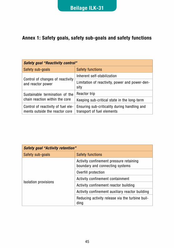
45
Beilage ILK-31
46
Annex 1: Safety goals, safety sub-goals and safety functions
Safety goal “Reactivity control”
Safety sub-goals Safety functions
Control of changes of reactivity and reactor power
Inherent self-stabilization
Limitation of reactivity, power and power-den-sity
Sustainable termination of the chain reaction within the core
Reactor trip
Keeping sub-critical state in the long-term
Control of reactivity of fuel ele-ments outside the reactor core
Ensuring sub-criticality during handling and transport of fuel elements
Safety goal “Activity retention”
Safety sub-goals Safety functions
Isolation provisions
Activity confinement pressure retaining boundary and connecting systems
Overfill protection
Activity confinement containment
Activity confinement reactor building
Activity confinement auxiliary reactor building
Reducing activity release via the turbine buil-ding
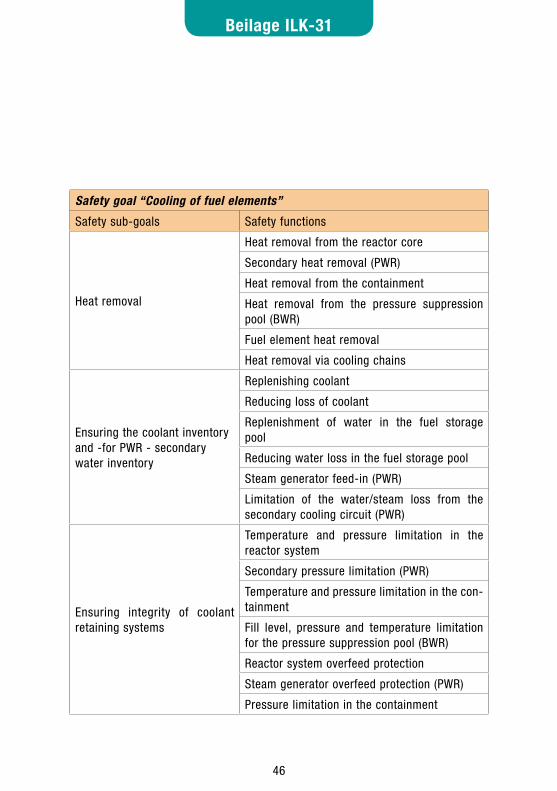
45 46
Beilage ILK-31
Safety goal “Cooling of fuel elements”
Safety sub-goals Safety functions
Heat removal
Heat removal from the reactor core
Secondary heat removal (PWR)
Heat removal from the containment
Heat removal from the pressure suppression pool (BWR)
Fuel element heat removal
Heat removal via cooling chains
Ensuring the coolant inventory and -for PWR - secondary water inventory
Replenishing coolant
Reducing loss of coolant
Replenishment of water in the fuel storage pool
Reducing water loss in the fuel storage pool
Steam generator feed-in (PWR)
Limitation of the water/steam loss from the secondary cooling circuit (PWR)
Ensuring integrity of coolant retaining systems
Temperature and pressure limitation in the reactor system
Secondary pressure limitation (PWR)
Temperature and pressure limitation in the con-tainment
Fill level, pressure and temperature limitation for the pressure suppression pool (BWR)
Reactor system overfeed protection
Steam generator overfeed protection (PWR)
Pressure limitation in the containment

47
Beilage ILK-31
48
Annex 2: Initiating events to be taken into account Abnormal operation (level of defense 2)
Reduced heat removal by the main steam and feed water system
Load rejection to auxiliary power (PWR and BWR) •
Turbine trip without opening of the bypass station (e.g. after loss of conden- •ser vacuum) (PWR and BWR)
Unintended closure of individual main steam shutoff valves (PWR) / pene- •tration valves (BWR)
Loss of offsite power, short duration (PWR and BWR) •
Failure of (one) all main feed pumps (PWR and BWR) •
Reduction of flow rate in the reactor cooling system
Failure of individual or all reactor coolant pumps / forced-flow pumps (PWR •and BWR)
Erroneous change of the reactivity and the power distribution
Erroneous withdrawal of control assemblies/rods/SS banks during power •operation (PWR and BWR)
Incorrect control function that leads to an increase of the flow in the reactor •cooling system (BWR)
Cold water feed into the reactor cooling system from connected systems •(e.g. bypass of the recuperative heat exchanger in the PWR volume control system or erroneous injection by makeup feed water system or failure of high-pressure pre-heaters in BWR)
Leakage of reactor coolant / reduction of coolant inventory
Operational leakages from steam generator heating tubes (PWR) •
Fuel element storage and handling
Water loss from the fuel storage pool (small operational leaks) (PWR and •BWR)
47 48
Beilage ILK-31
Accidents (level of defense 3)
Increased heat removal by the main steam and feed water system46
Rupture / leak in a main steam pipe after the outer isolation valve with •simultaneous steam generator tube damage (PWR)
Rupture / leak in a main steam pipe after the outer isolation valve (without •steam generator tube damage) (PWR)
Leak/rupture in the main steam pipe inside the containment (PWR) •
Leak/rupture in a main steam pipe in the reactor building (outside the con- •tainment) or in the turbine building (BWR)
Reduced heat removal by the main steam and feed water system
Unintentional closure of all main steam isolation valves (PWR) or steam line •isolation valves (BWR)
Failure of all operational feed water supplies (PWR and BWR) •
Leaks from pipes in the feed water piping system, in case of PWR also in •blowdown line and emergency feed pipe between the steam generator and the check valve (PWR and BWR)
Erroneous change of the reactivity and the power distribution
Erroneous withdrawal of control assemblies/rods/SS banks during power •operation with additional failure of response of protection devices (PWR and BWR)
Unintentional reactivity increase in sub-critical state or zero load (PWR and •BWR)
Rejection of the most effective control element (PWR and BWR) •
Drop out of the most effective control rod (BWR) •
Core subcooling due to main steam leak (PWR) •
Leakage of reactor coolant / reduction of coolant inventory47
Small leak inside the containment (PWR and BWR; pipes of the pressure •
46 The frequency of some of these events is significantly lower than 10-4 according to the available probabilistic analyses and would no longer be classified in the accident range according to current knowledge.
47 The frequency of some of these events – especially large ruptures - is significantly lower than 10-4 according to the available probabilistic analyses and would no longer be classified in the accident range
49
Beilage ILK-31
50
retaining boundary, small crack openings, open pressure relief lines in case of PWR)
Medium/large leak in the coolant pipes of the pressure retaining boundary •(depending on rupture preclusion quality <= 0.1 F, 2F) (PWR and BWR), special assessment of the 2F leak if break preclusion applicable
Steam generator tube failure (short duration, <= 2 F) with steam discharge •into atmosphere (PWR)
Leak in a instrument line containing reactor coolant in the annulus (PWR) or •reactor building (BWR)
Leak in the residual heat removal system at any position outside the con- •tainment vessel in the annulus (PWR) / in the reactor building (BWR) during residual heat removal operation
Leakage from the pressure suppression pool (BWR) •
Leak at the bottom of reactor pressure vessel (BWR) •
Release of radioactive materials from auxiliary systems or components
Leak in a pipe in the exhaust gas system / gas treatment system (PWR and •BWR)
Leak in a vessel with radioactively contaminated water (greatest radiologi- •cal impacts, waste water evaporator) (PWR and BWR)
Fuel element storage and handling
Fuel element damage during handling (PWR and BWR) •
Long duration failure of operational spent fuel pool cooling (PWR and •BWR)
Boron dilution in fuel storage pool (PWR, only when borated water in fuel •storage pool)
Incorrect allocation in the fuel storage pool (PWR) •
Water/steam ingress in fuel element dry storage (PWR and BWR) •
Potential general impact
Earthquakes (including consequential damages) (PWR and BWR) •

49 50
Beilage ILK-31
Annex 3: VO eventsInternal VO events
Leak in the main steam pipe in the annulus (PWR) •Prevented by design of main steam pipe as a double pipe •
Main steam pipe rupture between containment vessel and main steam •safety valve (PWR)Prevented by compact valve block outside the containment vessel •
Leak in the feed water pipe in the annulus (PWR) •Prevented/controlled by design of the feed water pipe as a double pipe; dam- •pened check valve inside the containment vessel
Leak in the steam generator blowdown pipe in the annulus (PWR) •Prevented by design of the blowdown pipe as a double pipe •
Turbine failure (PWR and BWR) •Controlled by arranging the turbine in accordance with the requirements of •RSK guideline 17.1
Overspeed of a main coolant pump during a loss of coolant accident •(PWR)Controlled by dropping the pump flywheel in the case of overspeed (cf. RSK •guideline 17.2)
Drop of a fuel element into the marginally sub-critical reactor core (BWR) •Prevented by suitable measures and devices •
Erroneous withdrawal of control rods during fuel loading (BWR) •Prevented by measures and installations that do not permit the withdrawal of •control rods during reactor loading and permit the loading only when all control rods are inserted.
Cold water transient in the reactor pressure vessel (BWR) •Prevented by ensuring that the coolant circulation pumps are not started after •a plant shutdown when all control rods are withdrawn
Main steam pipe rupture between the first and second isolation valve •(BWR)Prevented by high-quality implementation of the area between the inner and •outer valves
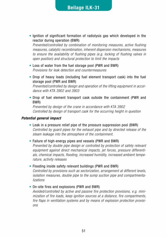
51
Beilage ILK-31
52
Ignition of significant formation of radiolysis gas which developed in the •reactor during operation (BWR) Prevented/controlled by combination of monitoring measures, active flushing •measures, catalytic recombination, inherent dispersion mechanisms, measures to ensure the availability of flushing pipes (e.g. locking of flushing valves in open position) and structural protection to limit the impacts
Loss of water from the fuel storage pool (PWR and BWR) •Provisions for leak detection and countermeasures •
Drop of heavy loads (including fuel element transport cask) into the fuel •storage pool (PWR and BWR)Prevented/controlled by design and operation of the lifting equipment in accor- •dance with KTA 3902 and 3903
Drop of fuel element transport cask outside the containment (PWR and •BWR)Prevented by design of the crane in accordance with KTA 3902 •Controlled by design of transport cask for the occurring height in question •
Potential general impact
Leak in a pressure relief pipe of the pressure suppression pool (BWR) •Controlled by guard pipes for the exhaust pipe and by directed release of the •steam leakage into the atmosphere of the containment.
Failure of high-energy pipes and vessels (PWR and BWR) •Prevented by double pipe design or controlled by protection of safety relevant •equipment against direct mechanical impacts, jet forces, pressure differenti-als, chemical impacts, flooding, increased humidity, increased ambient tempe-rature, activity releases
Flooding inside safety relevant buildings (PWR and BWR) •Controlled by provisions such as sectorization, arrangement at different levels, •isolation measures, double pipe to the sump suction pipe and compartmenta-lizations
On-site fires and explosions (PWR and BWR) •Avoided/controlled by active and passive fire protection provisions, e.g. mini- •mization of fire loads, keep ignition sources at a distance, fire compartments, fire flaps in ventilation systems and by means of explosion protection provisi-ons
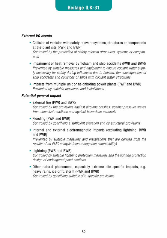
51 52
Beilage ILK-31
External VO events
Collision of vehicles with safety relevant systems, structures or components •at the plant site (PWR and BWR)Controlled by the protection of safety relevant structures, systems or compon- •ents
Impairment of heat removal by flotsam and ship accidents (PWR and BWR) •Prevented by suitable measures and equipment to ensure coolant water supp- •ly necessary for safety during influences due to flotsam, the consequences of ship accidents and collisions of ships with coolant water structures
Impacts from multiple unit or neighboring power plants (PWR and BWR) •Prevented by suitable measures and installations •
Potential general impact
External fire (PWR and BWR) •Controlled by the provisions against airplane crashes, against pressure waves •from chemical reactions and against hazardous materials
Flooding (PWR and BWR) •Controlled by specifying a sufficient elevation and by structural provisions •
Internal and external electromagnetic impacts (excluding lightning, BWR •and PWR)Prevented by suitable measures and installations that are derived from the •results of an EMC analysis (electromagnetic compatibility).
Lightning (PWR and BWR) •Controlled by suitable lightning protection measures and the lighting protection •design of endangered plant sections.
Other natural phenomena, especially extreme site-specific impacts, e.g. •heavy rains, ice drift, storm (PWR and BWR)Controlled by specifying suitable site-specific provisions •
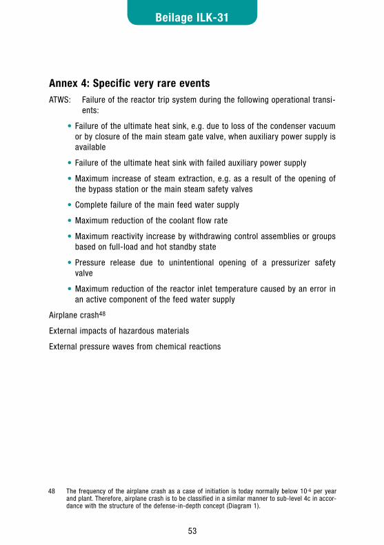
53
Beilage ILK-31
54
Annex 4: Specific very rare eventsATWS: Failure of the reactor trip system during the following operational transi- ents:
Failure of the ultimate heat sink, e.g. due to loss of the condenser vacuum •or by closure of the main steam gate valve, when auxiliary power supply is available
Failure of the ultimate heat sink with failed auxiliary power supply •
Maximum increase of steam extraction, e.g. as a result of the opening of •the bypass station or the main steam safety valves
Complete failure of the main feed water supply •
Maximum reduction of the coolant flow rate •
Maximum reactivity increase by withdrawing control assemblies or groups •based on full-load and hot standby state
Pressure release due to unintentional opening of a pressurizer safety •valve
Maximum reduction of the reactor inlet temperature caused by an error in •an active component of the feed water supply
Airplane crash48
External impacts of hazardous materials
External pressure waves from chemical reactions
48 The frequency of the airplane crash as a case of initiation is today normally below 10-6 per year and plant. Therefore, airplane crash is to be classified in a similar manner to sub-level 4c in accor-dance with the structure of the defense-in-depth concept (Diagram 1).
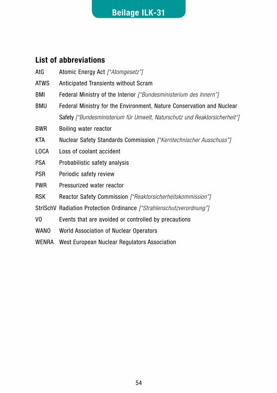
53 54
Beilage ILK-31
List of abbreviationsAtG Atomic Energy Act [“Atomgesetz”]
ATWS Anticipated Transients without Scram
BMI Federal Ministry of the Interior [“Bundesministerium des Innern”]
BMU Federal Ministry for the Environment, Nature Conservation and Nuclear
Safety [“Bundesministerium für Umwelt, Naturschutz und Reaktorsicherheit“]
BWR Boiling water reactor
KTA Nuclear Safety Standards Commission [“Kerntechnischer Ausschuss”]
LOCA Loss of coolant accident
PSA Probabilistic safety analysis
PSR Periodic safety review
PWR Pressurized water reactor
RSK Reactor Safety Commission [“Reaktorsicherheitskommission”]
StrlSchV Radiation Protection Ordinance [“Strahlenschutzverordnung”]
VO Events that are avoided or controlled by precautions
WANO World Association of Nuclear Operators
WENRA West European Nuclear Regulators Association
55
Beilage ILK-31
56
ReferencesAtG-2004, Gesetz über die friedliche Verwendung der Kernenergie und den Schutz
gegen ihre Gefahren (Atomgesetz (AtG)) vom 23. Dezember 1959, Stand nach dem siebenten Gesetz zur Änderung des Atomgesetzes (Artikelgesetz), BGBl 1994, Teil I Seite 1622
AtSMV, Verordnung über den kerntechnischen Sicherheitsbeauftragten und über die Meldung von Störfällen und sonstigen Ereignissen (Atomrechtliche Sicherheitsbeauftragten- und Meldeverordnung) vom 14. Oktober 1992 (BGBl. I 1992, Nr. 48)
CNS-D-2004, Bericht der Regierung der Bundesrepublik Deutschland für die dritte Überprüfungstagung zum Übereinkommen über nukleare Sicherheit, BMU, 2005
IAEA SF-1, Fundamental Safety Principles, IAEA, Vienna, 2006
IAEA NS-R-1, Safety of Nuclear Power Plants: Design, Safety Requirements, Safety Standards Series, IAEA, Vienna, 2000
IAEA NS-R-2, Safety of Nuclear Power Plants: Operation, Safety Requirements, Safety Standards Series, International Atomic Energy Agency, 2000
IAEA GS-R-3, The Management System for Facilities and Activities, Safety Requirements, Safety Standards Series, International Atomic Energy Agency, 2006
INSAG-12, Basic Safety Principles for Nuclear Power Plants, 75-INSAG-3 Rev. 1, International Nuclear Safety Advisory Group, IAEA, Vienna (1999)
KEV-2004, Kernenergieverordnung (KEV) der Schweiz, 2004
KTA-2002, Sicherheitsgrundlagen, Regelvorlagenentwurf im Rahmen des Projekts KTA 2000, Dezember 2002
PSÜ-Leitfaden, Leitfäden zur Durchführung von periodischen Sicherheitsüberprüfun-gen (PSÜ) für Kernkraftwerke in der Bundesrepublik Deutschland, August 1997: Grundlagen zur periodischen Sicherheitsüberprüfung, Dezember 1996
RSK-1979, Rahmenspezifikation "Basissicherheit von druckführenden Komponenten", Anhang zu den RSK-Leitlinien für Druckwasserreaktoren in der 2. Ausgabe vom 24. Januar 1979, Stand: 25. April 1979
RSK-1992, Behandlung auslegungsüberschreitender Ereignisabläufe für die in der Bundesrepublik Deutschland betriebenen Kernkraftwerke mit Druckwasserreaktoren, Positionspapier der RSK zum anlageninternen
55 56
Beilage ILK-31
Notfallschutz im Verhältnis zum anlagenexternen Katastrophenschutz, Empfehlung der RSK, Anlage 1 zum Ergebnisprotokoll der 273. RSK-Sitzung am 09.12.1992
RSK-LL, RSK-Leitlinien für Druckwasserreaktoren, 3. Ausgabe vom 14. Oktober 1981 mit Änderungen vom 15.11.1996
Sicherheitsanforderungen für Kernkraftwerke: Grundlegende Sicherheitsanforderun-gen, Modul 1, Revision B, GRS, September 2006
SiKri, Sicherheitskriterien für Kernkraftwerke vom 21.10.1977, BMI, 1977, BAnz. 1977, Nr. 206
SiKri-Einzelfehler, Interpretationen zu den Sicherheitskriterien für Kernkraftwerke; Einzelfehlerkonzept - Grundsätze für die Anwendung des Einzelfehlerkriteriums vom 2.3.1984 (GMBl. 1984, S. 208)
Störfall-LL, Leitlinien zur Beurteilung der Auslegung von Kernkraftwerken mit Druckwasserreaktoren gegen Störfälle im Sinne des § 28 Abs. 3 StrlSchV 18.10.1983 (BAnz. 1983, Nr. 245a)
StrlSchV-2002, Verordnung über den Schutz vor Schäden durch ionisierende Strahlen (Strahlenschutzverordnung) vom 20. Juli 2001 (BGBl.I 2001, Nr. 38), zuletzt geändert durch VO vom 18. Juni 2002 (BGBl.I 2002, Nr. 36)
WENRA-2007, Reactor Safety Reference Levels, WENRA, January 2007

57
Beilage ILK-31
58
57 58
Beilage ILK-31
Note:
This is a translation by ILK of the German report,
which has been prepared by ISaR GmbH
by order of the ILK Administrative Office at the Bavarian Environment Agency.
ILK - Geschäftsstelle beim Bayerischen Landesamt für Umwelt
Bürgermeister-Ulrich-Str. 160
D-86179 Augsburg
GERMANY
Phone: +49-173-65 707-10/-11
Fax: +49-173-65 707-96/-98
E-Mail: [email protected]
http://www.ilk-online.org