experimental simulation trial for human lung's flow...
TRANSCRIPT

ヒトの肺の流れの力学解明に向けた実験的シミュレーション
Experimental simulation trial for human lung's flow mechanism
2016/6/10 1
Hiroyuki HIRAHARA 平原裕行
Division of Human Support and
Production Science人間支援・生産科学部門
Saitama University 埼玉大学

Get ‘REAL SOLUTION’ ?Or
Get ‘ESSENCE’?
2016/5/09 2
Conventional Way
EFD CFD
V & V
Promoting Way
EFD CFD
Check and Review
For Inovation

3
Today’s presentation
1) Irreversible Laminar Flow in Peripheral Lungs
2) Coanda effect simulation
What we should remove from complex factor ?
Potential ? or Viscous ?
Complete viscous (laminar) !
But, something happen.

2016/5/09 4
223 bifurcations makes intricate structure
Fig.2 Delivery of Oxygen and Carbon Dioxide
In the Respiratory System
Oxygen-rich
air from
environment
Nasal
cavitiesPharynx Trachea Bronchi
BronchiolesAlveoli
Oxygen and
carbon dioxide
exchange at
alveoli
BronchiolesBronchi
Trachea PharynxNasal
cavities
Carbon
dioxide-rich
air to the
environment
Fig.1 Macroscopic view of a plastic cast of the airways (yellow) the pulmonary
arteries (red) and veins (blue) of a human lung. (Anatomy Institute of Anatomy,
University of Berne, Switzerland)

High-frequency oscillatory ventilation: Mechanisms of gas exchange and lung
mechanics
J. Jane Pillow, MBBS, FRACP, PhD
Crit Care Med 2005 Vol. 33, No. 3 (Suppl.)

CHANG, H. K.
Mechanisms of gas transport during ventilation by high frequency oscillation.
J. Appl. Physiol.: Respirat. Environ. Exercise Physiol. 56( 3): 553-563, 1984.-
5 flow modes by Chang(1984)
Ventilation by high-frequency oscillation (HFO) presents some difficulties in understanding exactly how gas is transported
in the lung. However, at a qualitative level, five modes of transport may be identified:
1 ) direct alveolar ventilation in the lung units situated near the airway opening;
2) bulk result of recirculation of convective mixing air among units of in the conducting airways as a inhomogeneousti me
constants;
3) convective transport of gases-as a result of the asymmetry between inspiratory and expiratory velocity profiles;
4) longitudinal dispersion caused by the interaction between axial velocities and radial transports due to turbulent eddies and/or
secondary swirling motions
5) molecular diffusion near the alveolocapillary membrane. These modes of transport are not mutually exclusive and certainly
interact. It is therefore difficult to make quantitative predictions about the overall rate of transport. Qualitatively,
it may now be stated with confidence that convective transport in the tracheobronchial tree is very important during HFO as in
normal
breathing and . that increasing tidal volu .me is more effective than increa sing frequency in improving gas exchange during HFO.
To optimi .ze the gas transport efficiency of HFO, future research should focus on identifying the rate-li .miting mode of transport
for a given set of geometric and dynamic conditions.
FIG. 9. Modes of gas transport during high-frequency oscillation
(HFO) and
tentative sketch of their zones of dominance. These modes of
transport are not mutually exclusive and may interact to achieve
observed efficiency in animal or patient studies.
General

2016/5/09 7
Fig.20 Velocity distribution in the bifurcation plane and two
cross sections at 7th generation: (A) end inspiration, (B) end
expiration.
Blue, negative axial velocity to the left; Red, positive axial
velocity to the right. (Choi et al. 2010)
Fig.19 Illustration of
Pendelluft mechanism
(H. Hirahara)
Pendelluft Flow
Coaxial FlowTaylor
Dispersion
Flow
3. GAS FLOW IN BRONCHIOLES INDUCED BY HFOV
3.1 Introduction of HFOV

2016/5/09 8
What parameters should be considered ?
Fig.3 Flow regimes of the conducting airway categorized on the basis of a
dimensionless frequency α2 (where α is the Womersley number) and a
dimensionless stroke length L/a. Jan et al.
Fig.4 Re, Pe, and Wo numbers for TV=150mL at each generation.
(Hirahara, 2010, J of Fluid and Science Technology)

9
Reynolds number is not only similarity parameter,But also momentum diffusion speed !
𝑅𝑒 =𝑈𝐿
𝜈=
𝑈
𝜈/𝐿=
Convective speed
Momentum Diffusion speed
𝑃𝑒 =𝑈𝐿
𝛼=
𝑈
𝛼/𝐿=
Convective speed
Molecular Diffusion speed
Peclet number is also important,
𝜈: viscousity
𝛼:𝑚olacular diffusion coefficient

2016/5/09 10Fig.5 Bifurcating structure of human
lung based on Weibel’s model
1. The Weibel’s lung model is symmetric and relatively
simple, it helps to diminish the disturbance of over-complex
structure, to get more general and representative gas flow
phenomena.
2. The weibel’s lung model facilitates not only numerical
simulation but also PIV experiment.
Why we will not use CT data ?

2016/5/09 11
Why the bronchioles is target ?
(below G18)
1. Almost all researchers focus on upper-airway flow
above G10. What happens at the distal region?
2. HFOV adopts fast and shallow oscillatory ventilation,
the small tidal volume cannot reach the respiratory zone
at each oscillation. How can HFOV be effective in
ventilation? How can fresh gas reach the distal region?
only by molecular diffusion? Or by some progressive
delivery?
Fig.6 Illustration of main research region and reachable
area of single tidal volume of HFOV

2016/5/09 12
What happens in High frequency respiration ?
Conventional Ventilation
Or Normal Breathing
High Frequency
Oscillatory Ventilation
Super-High Frequency
Oscillatory Ventilation
About 0.2Hz About 10Hz 100Hz…f
About 500ml About 50ml 5ml 10ml…TV
f × TVVT (constant) =Basic principle:
Normal HVOV Super-HFOV

2016/5/09 13
Numerical modeling
Dimensions of mother to grand-daughter tubes from G18 to G20 (left) and volume mesh (right)
Inlet
Outlets

Governing Equations
Boundary conditions for inlet
Boundary conditions for outlets
Boundary conditions for peripheral wall Rigid wall with non-slip condition
Fundamental condition of CFD
without molecular diffusion
without turbulent model

2016/5/09 15
Fig.9 Setting for VOF
calculation by 2 fluids
(Molecular diffusion neglected)
Fig.10 Setting for VOF
calculation with 4 fluids
(Molecular diffusion neglected)
Fig.8 Lagrangian particles setting
at different locations
Gas exchange in ‘Normal Breath’
at different position

2016/5/09 16
Fig.11 Particle fluctuations in G18-G20 by CV (sinusoidal, 0.2Hz, 500mL) in 5 seconds
Gas exchange in ‘Normal Breath’
at different position

2016/5/09 17
Gas exchange in ‘Normal Breath’
at different position
VOF calculation for Normal Breath
(sinusoidal, 0.2Hz, 500mL) in 5 seconds

2016/5/09 18
5 seconds later
Gas exchange in ‘Normal Breath’
Gas redistribution due to large TV

2016/5/09 19
Fig.23 Setting for VOF
calculation with 2 fluids
(Molecular diffusion neglected)
Fig.24 Setting for VOF
calculation with 4 fluids
(Molecular diffusion neglected)
Fig.22 Lagrangian particles at the same locations of
VOF interfaces in Fig.12

2016/5/09 20Fig.25 Particle fluctuations in G18-G20 by HFOV (sinusoidal, 10Hz, 50mL) in 5 seconds
GAS FLOW IN BRONCHIOLES INDUCED BY HFOV

2016/5/09 21
Redistribution of massless particles caused by raking effect in G18 with
HFOV(Sinusoidal, 10Hz, 50ml) in 3 cycles (0.3seconds)
3-D View of Lagrangian tracking

2016/5/09 22
Fig.26 VOF calculation for HFOV (10Hz, 50mL, sinusoidal) in 5 seconds
GAS FLOW IN BRONCHIOLES INDUCED BY HFOV

2016/5/09 23
Fig.27 VOF calculation for HFOV (10Hz, 50mL, sinusoidal) in 5 seconds
0 second 0.3 seconds 1 second 5 seconds
GAS FLOW IN BRONCHIOLES INDUCED BY HFOV

Fig.28 Comparison of gas rearrangement in G18-G20 with CV (sinusoidal, 0.2Hz, 500mL)
and HFOV (sinusoidal, 10Hz, 50mL) in 5 seconds
VS
VS
Normal HFOV

2016/5/09 25
HFOV rakes the gas near the central-axis downwards and the peripheral
gas upwards much more than CV does, which is named raking effect here, it
features similar effect of the coaxial counter-flow.
A significant difference between raking effect and counter-flow is that
raking effect doesn’t apparently involve flows in two opposite directions
simultaneously. Raking effect can be seen due to irreversibility as a time-
average effect in laminar flow within a tiny space where viscous force is
dominant.
Conclusion 1
Conclusion 2

2016/5/09 26
PIV experiment in Real Scale !
Micro-PIV(Particle Image velocimetry) Measurement
2016/5/09 27
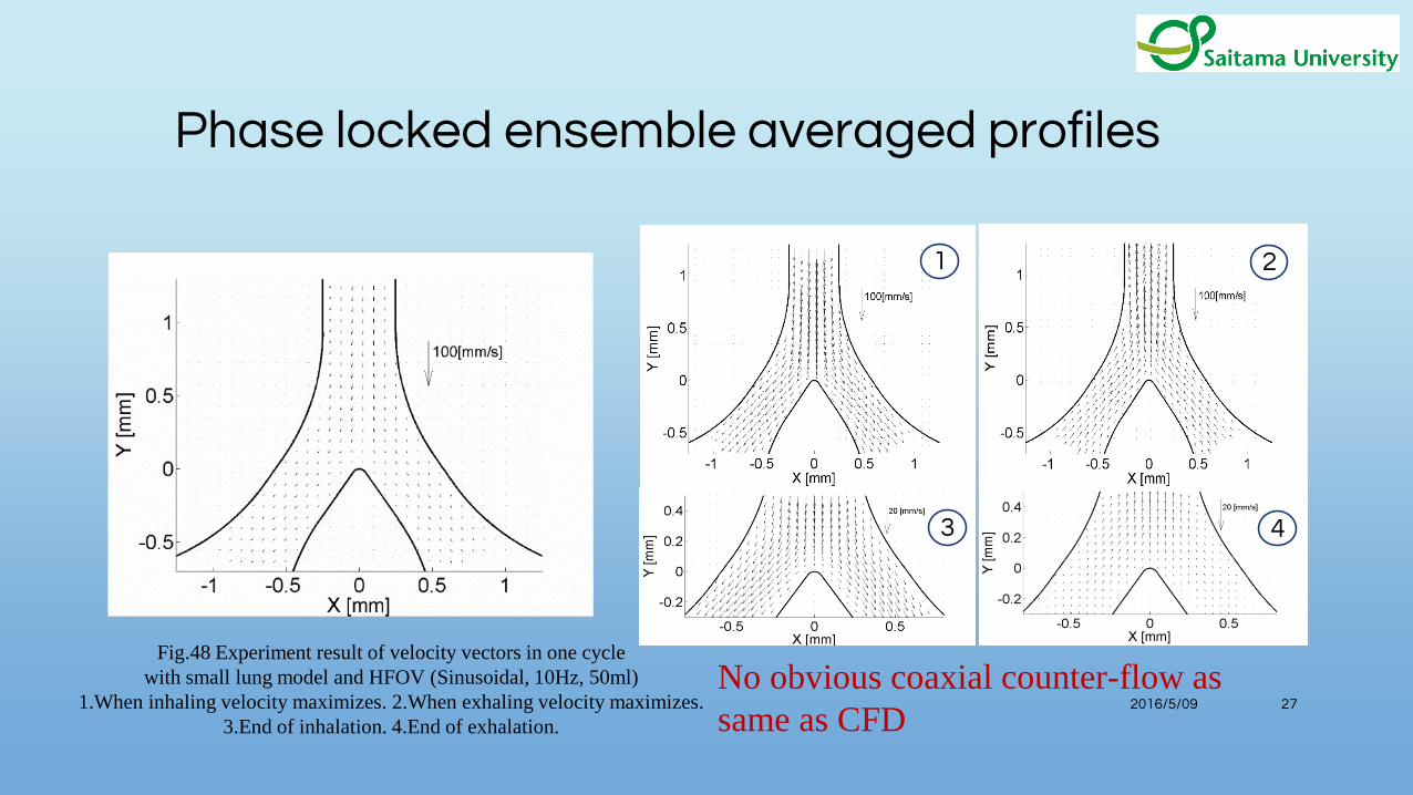
No obvious coaxial counter-flow as
same as CFD
Fig.48 Experiment result of velocity vectors in one cycle
with small lung model and HFOV (Sinusoidal, 10Hz, 50ml)
1.When inhaling velocity maximizes. 2.When exhaling velocity maximizes.
3.End of inhalation. 4.End of exhalation.
1
43
2
Phase locked ensemble averaged profiles

2016/5/09 28
Fig.49 Experiment result of particle tracks in one cycle with small lung model and HFOV (Sinusoidal, 50ml, 10Hz(1) /20Hz (2))
(1) (2)
Lagrangian tracking shows the ‘raking effect’

2016/5/09 29
6 modes of
transport in
HFOV
1. Direct ventilation
2. Mixing by Pendelluft or out-of-phase oscillation
3. Convective dispersion due asymmetry between
inspiratory and expiratory velocity profile
4. Longitudinal dispersion due to turbulent eddies
and/or secondary swirling motions
5. Molecular diffusion
6. Raking effect (distal region)
6th mode is important in distal region
5 modes of
transport in
HFOV
1. Direct ventilation
2. Mixing by Pendelluft or out-of-phase oscillation
3. Convective dispersion due asymmetry between
inspiratory and expiratory velocity profile
4. Longitudinal dispersion due to turbulent eddies
and/or secondary swirling motions
5. Molecular diffusion

Fig.52 Comparison of raking effect with different gas viscosity
(1.983×10⁻⁵ Pa·S for the left, 1.983×10⁻³ Pa·S for the right) by
HFOV (sinusoidal, 10Hz, 50ml) at the end of 1 second
Geometric
shape of
airways ?
Viscosity ?
1 second
comparison
HFOV with
normal air
HFOV with
much more
viscous air
f (Frequency) 10Hz 10Hz
TV (Tidal Volume) 50ml 50ml
Local TV 50ml/218 50ml/218
Gas viscosity 1.983E-5Pa·S 1.983E-3Pa·S
Replaced Volume 3.12E-5ml 3.56E-5ml
Fresh gas
movement
deep deep
6th mode depends on VISCOUSITY ?

2016/5/09 31
For the case of 150ml tidal volume oscillated with 10Hz
frequency. Within the area between G18 and G20:
Fig.51 Re, Pe, and Wo numbers for TV=150mL at each generation. (Yamamoto, 2010)
Re<10, Wo<1, Pe≈1 indicates that viscous laminar
flow and parabolic quasi-steady flow are dominant
in this region, advective transport rate and diffusive
transport rate are in the same order of magnitude.
Viscosity ?Geometric
shape of
airways ?
6th mode, Raking Effect’ is effective at more high frequency ?

2016/5/09 32
4.2 Numerical calculation (effect of super-high-frequency)
4. PRELIMINARY INVESTIGATION OF SUPER-HFOV
Fig.66 Particle oscillation at G18 by HFOV (sin, 20Hz, 25ml, left) (sin, 50Hz, 10ml, middle) (sin, 75Hz, 6.7ml, right)

2016/5/09 33
4. PRELIMINARY INVESTIGATION OF SUPER-HFOV
Sinusoidal,
100Hz, 5ml
Sinusoidal,
100Hz, 10ml
Sinusoidal,
100Hz, 20ml
Fig.67 Lagrangian and VOF calculation at G18 by HFOV (sin, 100Hz, 5ml, left) (sin, 100Hz, 10ml, middle) (sin, 100Hz, 20ml, right)
2016/5/09 34
Raking effect is effective with frequency increasing (Super-HFOV)
An local region exists where the raking effect is excited. However, we did
not identify it yet.
Conclusion 3
Conclusion 4

35
2nd Problem
Coanda effect simulation
Drag reduction of motor vehicles by
active flow control using the Coanda
effect, D. Geropp, H.J. Odenthal, Exp.
In Fluids, 28(2000) 74-85.
Design methods of Coanda effect nozzle with two streams
Michele TRANCOSSI*,1, Antonio DUMAS1, Shiam Sumantha DAS2,
Jose PASCOA2 , INCAS BULLETIN, Volume 6, Issue 1/ 2014, pp. 83 – 95

36
Flow
Molecular force
Why Coanda effect is problem ?
Continume Viscous
SeparationBending
Continuous
derivative
Boundary layer
Separation
Momentum
transfer
Continuity N-S equations

37
Usual No-slip

38
Slip

39
What happens at
the starting ?
Usual No-slip

40
Slip

41
Conclusion 5
Experimental simulation trial including the potential flow analysis is
fruitful like a discussion on Coanda effect. Also, criteria of continuity
condition should be examined within CFD.