estudio de regiones activas solares a través de técnicas de diversidad de fase
TRANSCRIPT

Estudio en Alta Resolución de Regiones Activas Solares Estudio en Alta Resolución de Regiones Activas Solares a través de Técnicas de Diversidad de Fasea través de Técnicas de Diversidad de Fase
La Laguna - Tenerife, Septiembre de 2006La Laguna - Tenerife, Septiembre de 2006
Santiago Vargas DomínguezSantiago Vargas Domínguez
PROYECTO DE TESIS DOCTORALPROYECTO DE TESIS DOCTORAL
Directores: Jose A. Bonet & Valentín Martínez PilletDirectores: Jose A. Bonet & Valentín Martínez Pillet

Contenido
1. Introducción Teórica
1.1 Restauración de imágenes solares 1.2 Estructura fina en regiones activas solares
2. Objetivos
3. Metodología
3.1 Observaciones 3.2 Reducción y tratamiento de los datos 3.3 Análisis y resultados
4. Plan de trabajo

Contenido
2. Objetivos
3. Metodología
3.1 Observaciones 3.2 Reducción y tratamiento de los datos 3.3 Análisis y resultados
4. Plan de trabajo
1. Introducción Teórica
1.1 Restauración de imágenes solares 1.2 Estructura fina en regiones activas solares
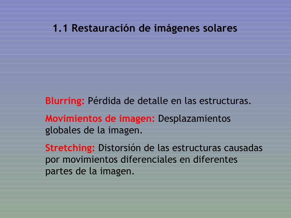
1.1 Restauración de imágenes solares
Blurring: Pérdida de detalle en las estructuras.
Movimientos de imagen: Desplazamientos globales de la imagen.
Stretching: Distorsión de las estructuras causadas por movimientos diferenciales en diferentes partes de la imagen.

A feeling on the influence of the telescope aperture, the AO and the restoration codes
SVST (ORM)Ø50 cmAO non activeJul 7, 1999G-band 4305 ÅRebined x2 tohave 0.041”/pix
SST (ORM)Ø100 cmAO activeJul 15, 2002G-band 4305 Åpix=0.041”
Both images restored with Phase diversity
before after
restoration
SST (ORM)Ø100 cmAO active + PD correctionSep 30, 2003G-band 4305 Åpix=0.041”

...
Formación de imagen con luz incoherente
),( donde
),(),(),(0
yx
dtstiti
q
qqqqq
Point Spread Function (PSF)
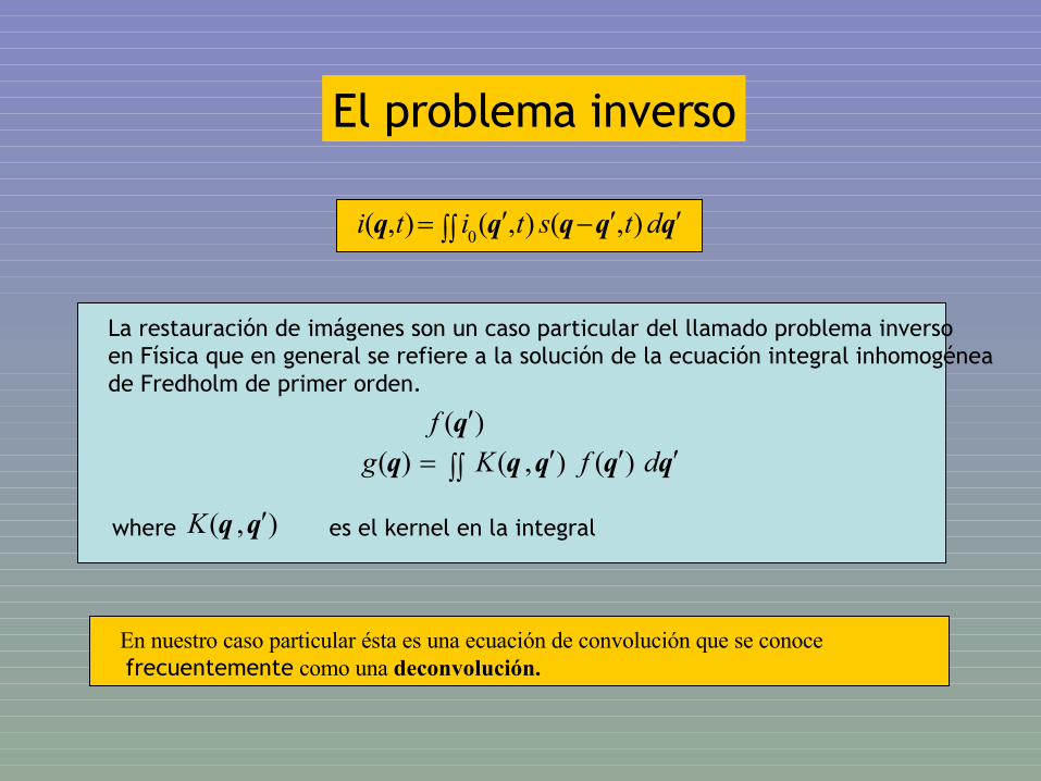
El problema inverso
La restauración de imágenes son un caso particular del llamado problema inverso en Física que en general se refiere a la solución de la ecuación integral inhomogéneade Fredholm de primer orden.
qqqqq dtstiti ),(),(),(0
qqqqq dfKg )(),()()(qf
),( qq Kwhere es el kernel en la integral
En nuestro caso particular ésta es una ecuación de convolución que se conoce frecuentemente como una deconvolución.
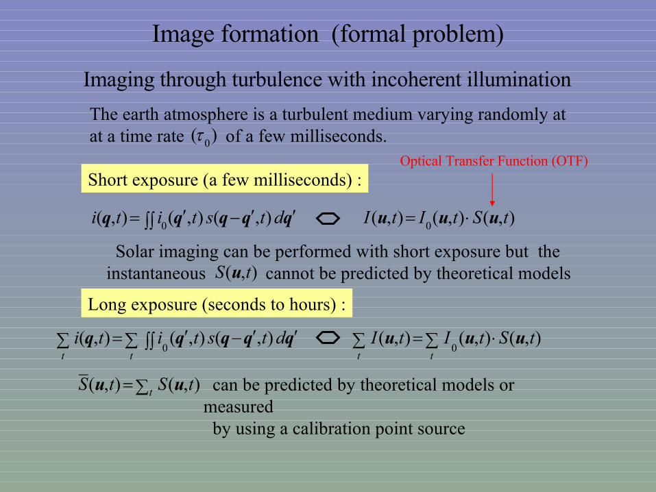
Image formation (formal problem)
Imaging through turbulence with incoherent illumination
qqqqq dtstiti ),(),(),(0
),(),(),(0
tStItI uuu
The earth atmosphere is a turbulent medium varying randomly atat a time rate of a few milliseconds.)(
0
Short exposure (a few milliseconds) :
Solar imaging can be performed with short exposure but the instantaneous cannot be predicted by theoretical models
Long exposure (seconds to hours) :
tt
dtstiti qqqqq ),(),(),(0
tt
tStItI ),(),(),(0
uuu
),( tS u
t tStS ),(),(_
uu can be predicted by theoretical models or measured by using a calibration point source
Optical Transfer Function (OTF)
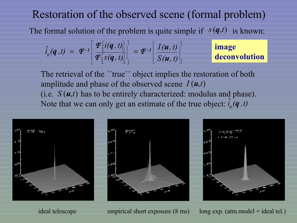
The formal solution of the problem is quite simple if is known: ),( ts q
Restoration of the observed scene (formal problem)
t),(S
t),(It),(s
t),(it),(i
u
uq
qq 1-1- F
F
FF
0ˆ
The retrieval of the ´´true´´ object implies the restoration of both amplitude and phase of the observed scene (i.e. has to be entirely characterized: modulus and phase).Note that we can only get an estimate of the true object:
),( tS u),( tI u
ideal telescope empirical short exposure (8 ms) long exp. (atm.model + ideal tel.)
imagedeconvolution
t),(i q0ˆ

Image formation (real problem)
Any observed image will contain noise: photon noise, reading noise, etc...
Noise uncorrelated with the level of the signal is often a good approximation.Thus, for a fixed time (short exposure):
)()()()()()()(00
qqqqqqqqq nsindsiin
)()()()()()(0
uuuuuu NINSIIN
And the restoration gives:)(
)(
)(
)(
)(
)(
u
u
u
u
u
u
S
N
S
I
S
IN
The term represents an amplification of the noise
Disastrous effect particularly at high frequencies where the SNR is small.
)(
)(
u
u
S
N
)()()()()()( uuuuuuNNNF
NIII
Therefore, noise filtering is demanding prior to any restoration process:

The “optimum” noise filter, is a real function which weights according to its SNR at each frequency
Condition defining the filter:
minimum a )()()()(
222 uuuqqu dIIdqiidFF
(where ε denotes the residual error), and by substitution of results: )(uF
I
minimum a )()()(1)(2
uuuuu dNI
NN
Considering that i(q) and n(q) are not correlated, and developing the squared modulus:
minimum a )()()(1)( 22222
uuuuuu dNId
NN
A standard calculus of variations leads to:
0)()(2)(1)(2 222
uuuu
NN
N
NI
or equivalently:2
22
22
2
)(
)()(
)()(
)()(
u
uu
uu
uu
N
NN
I
NI
NI
I
The non correlation between i(q) and n(q) has allowed to use:
)()()()()()( uuuuuuNNNF
NIII
)(uN
I
222 )()()( uuu NIIN
)(uN
)(Nu

22
22
2
22
22
2
)()(
1)()(
)(
)()(
)()(
)()(
uu
uu
u
uu
uu
uu
NI
NI
I
NI
NI
I
N
N
N
NN
Thus, the filter is a weighting real function determined by the ratio of power between the observed signal and the noise
Dibujo a mano alzada del filtroY 3 panels de la fig. De la tesis e Monica
2)(u
NI 2)(uN
Decir aqui lo de os modelos suaves analiticos
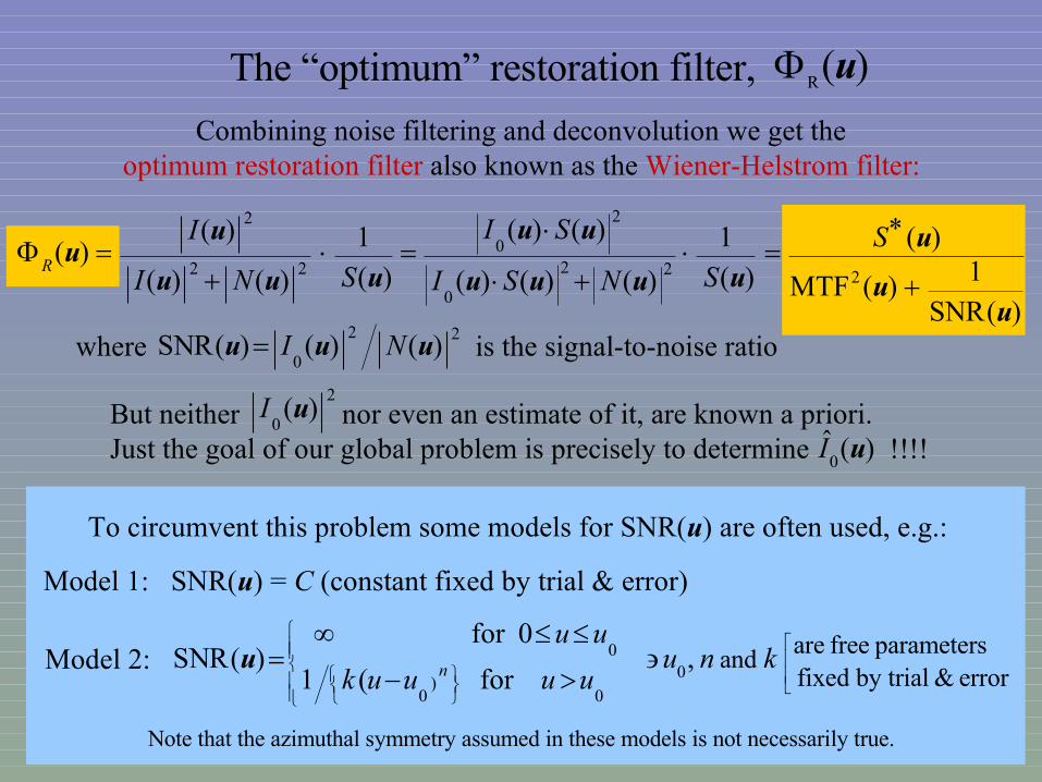
The “optimum” restoration filter, )(Ru
Combining noise filtering and deconvolution we get the optimum restoration filter also known as the Wiener-Helstrom filter:
)(SNR
1)(MTF
)(
)(
1
)()()(
)()(
)(
1
)()(
)()(
222
0
2
022
2
uu
u
uuuu
uu
uuu
uu
S
SNSI
SI
SNI
IR
where is the signal-to-noise ratio22
0)()()(SNR uuu NI
But neither nor even an estimate of it, are known a priori.Just the goal of our global problem is precisely to determine !!!!
2
0)(uI
)(ˆ0uI
To circumvent this problem some models for SNR(u) are often used, e.g.:
Model 1: SNR(u) = C (constant fixed by trial & error)
Model 2: ,for (1
0for )(SNR
error & by trial fixed parameters free areand
00
)0
0
knu
uuuuk
uunu
Note that the azimuthal symmetry assumed in these models is not necessarily true.

xdxxsxhxdy)dy-,x-s(xxh),i(x )(~)(0)(0
Straightforward calculation of from the equation: )(~ xs
A nice property of the convolution of h(x) with a given function f(x) :
)()()( xfxh
dxdxf
Applying this property to i(x,0) :
)(~)(0)(~
xsxhdxd
dx),i(xdxs
Once has been determined the calculation of its Fourier transform gives:)(~ xs
)0,(02exp),(2exp),()(~xxx
uSdydxyxujyxsdxxujdyyxsxs
F
Which is the section of the desired OTF along the x-frequency axis.Assuming azimuthal symmetry, a estimate of the OTF is obtained by rotationof .
S)0,(
xuS
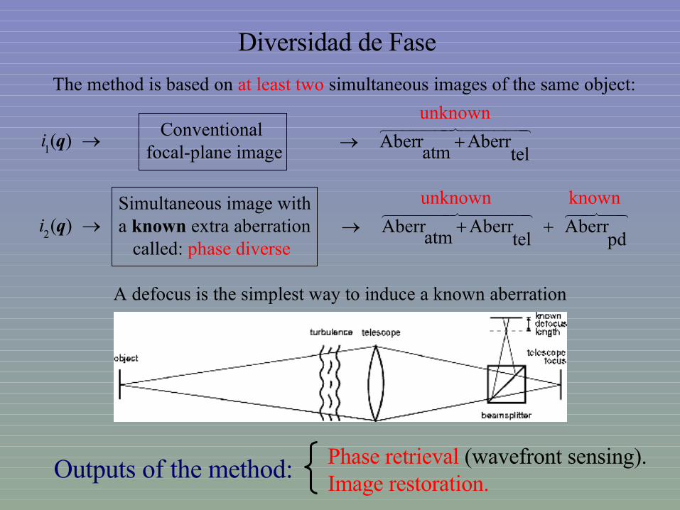
Diversidad de Fase The method is based on at least two simultaneous images of the same object:
telAberr
atmAberr
pdAberr
telAberr
atmAberr
Conventional focal-plane image
Simultaneous image witha known extra aberration called: phase diverse
)(1qi
)(2qi
unknown
unknown known
A defocus is the simplest way to induce a known aberration
Outputs of the method: Phase retrieval (wavefront sensing).Image restoration.
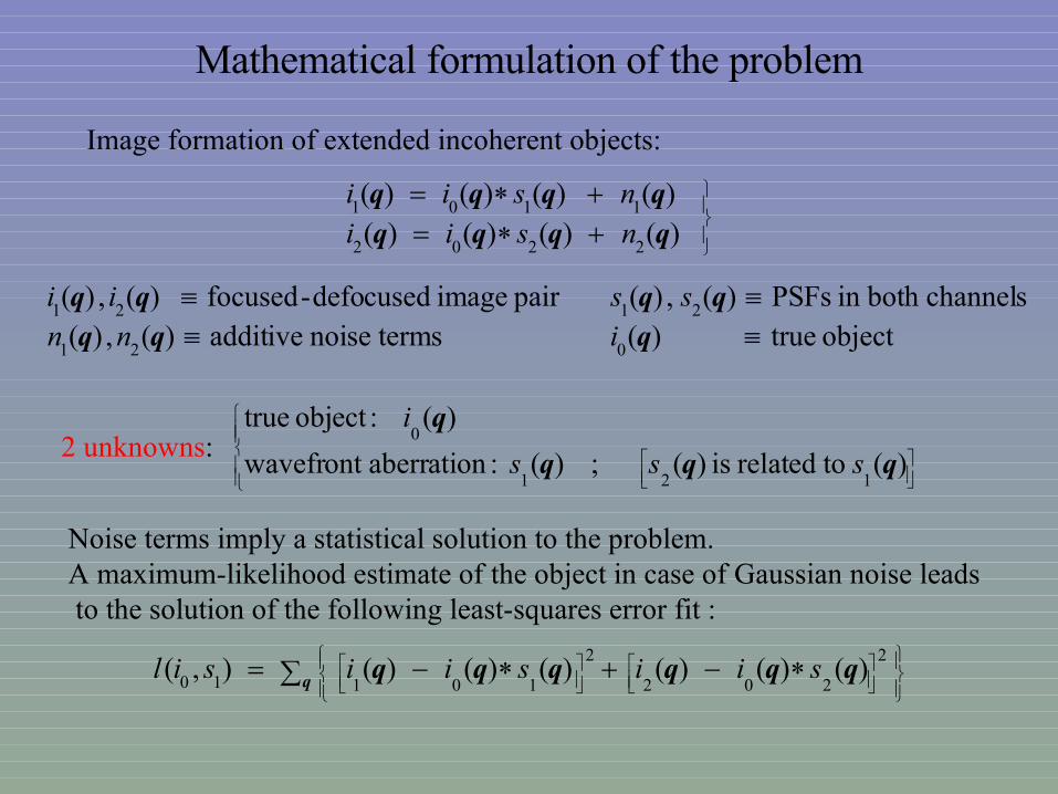
Mathematical formulation of the problem
Image formation of extended incoherent objects:
)()()()()()()()(
2202
1101
qqqqqqqq
nsiinsii
object true)( termsnoise additive)(,)(channelsboth in PSFs)(,)( pair image defocused-focused)(,)(
021
2121
qqqqqqq
innssii
2 unknowns:
)( torelated is )( ; )( :aberrationwavefront
)( :object true
121
0
qqq
q
sss
i
Noise terms imply a statistical solution to the problem. A maximum-likelihood estimate of the object in case of Gaussian noise leads to the solution of the following least-squares error fit :
q qqqqqq2
202
2
10110)()()()()()(),( siisiisil

The error metric in the Fourier domain:
u uuuuuu2
202
2
10110)()()()()()(),( SIISIISIL
)(~
)}(~
{exp)( )(
)()()(
/ variancesnoise of ratio 22
21
r
rrr
rurru
iHH
dfHHS
}...,,2,1,{ coefs.: aberr. in edparametriz are and OTF thei.e.
),()()()(exp)( )(
})({ :functions basis ofset convenient a usingby edparametriz becan )(~
01
JjJL
ILSiHH
j
Jj jj
j
α
αα,urrrr
rr
OTF
Generalized pupil function
Joint phase aberration caused by telescope and turbulence
) of casein 0 ( phase diverse)(1
Sr

u αuuuαuuuα2
202
2
1010),()()(),()()(),( SIISIIIL
In principle, numerical non-linear optimization techniques are suitable to minimize
),(0αIL
)(0uI
),( αuSbut there are too many unknowns !!! N x M pix in
and J aberr.coeffs in
Fortunately, part of the minimization of can be done analytically !!!),(0αIL
2
2
2
1
22110
0
0
),(),(
),()(),()()(ˆ0
),(
αuαu
αuuαuuu
α
SS
SISII
IIL
2
2
2
2
1
1221
),(),(
),()(),()()(
u αuαu
αuuαuuα
SS
SISILM
substitution in gives a modified error metric:
Objectestimate
Modified error metricwhere the only explicit unknowns are the J aberr.coeffs. α
Minimization of wavefront sensing)(αML

2
2
2
2
1
1221
),(),(
),()(),()()(
u αuαu
αuuαuuα
SS
SISIL
jj
M
)(αMLMinimization of : posing the problem
Jj jj
iHH
HHS
1 )()(exp)( )( and
)()()( where
rrrr
αu,αu,αu,
The conditions of minimum with respect to the free parameters definingthe model of S : (the aberration coeffs.),give rise to a non-linear system of equations:
}...,,2,1,{ Jjj α
(J equations)
)10),(
theasken usually ta are ,),( pupil in the scoordinatepolar in or ),(
jZjj
:Zernike of spolinomial circle orthogonal
r

Linearization of the problemA more compact notation:
u
αu,α 2)()( ELM 2
2
2
1
1221
),(),(
),()(),()()( where
αuαu
αuuαuuαu,
SS
SISIE
A Taylor´s series expansion of E around α gives:
u
u
uu
uu
αu,
αu,αα,uαα
αu,αα,u
equations) ( 0
equations) ( 0Re2)(
)()()(
21)()(
1
2
22
M
,
2
:min. of conditions theresulting real, is since omitted becan above ``Re´´ symbol The
:as expressed becan minimum of conditions the,by )( denoting
:as metricerror theeapproximat , intoon substituti andorder first thebeyond truncation
JEEEE
JEEEEEE
EEEL
EEEE
J
ii
ijj
jji
iii
ii
i
M
jii ji ji
ii
EE
L
0
EE
EE
EE
EEEEEE
EEEEEE
EEEEEE
JJJJJJ
J
J
2
12
1
21
22212
12111
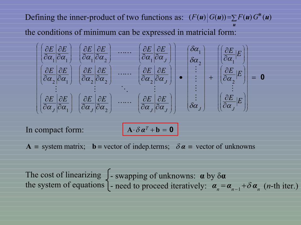
Defining the inner-product of two functions as:
the conditions of minimum can be expressed in matricial form:
u
uuuu )()())()(( GFGF
0 bA TαIn compact form:
The cost of linearizingthe system of equations
- swapping of unknowns: α by δα- need to proceed iteratively: (n-th iter.)
1 nnnααα
unknowns of vector s;indep.term ofvector matrix; system α bA

Image formation (real problem)
Any observed image will contain noise: photon noise, reading noise, etc...
Noise uncorrelated with the level of the signal is often a good approximation.Thus, for a fixed time (short exposure):
)()()()()()()(00
qqqqqqqqq nsindsiin
)()()()()()(0
uuuuuu NINSIIN
And the restoration gives:)(
)(
)(
)(
)(
)(
u
u
u
u
u
u
S
N
S
I
S
IN
The term represents an amplification of the noise
Disastrous effect particularly at high frequencies where the SNR is small.
)(
)(
u
u
S
N
)()()()()()( uuuuuuNNNF
NIII
Therefore, noise filtering is demanding prior to any restoration process:

Contenido
1. Introducción Teórica
1.1 Restauración de imágenes solares 1.2 Estructura fina en regiones activas solares
2. Objetivos
3. Metodología
3.1 Observaciones 3.2 Reducción y tratamiento de los datos 3.3 Análisis y resultados
4. Plan de trabajo

Estructura fina en regiones activas solares
Campo magnético que se genera bajo la zona de convección emerge a la superficie en las regiones activas.
Manchas solares
Poros
SST - La Palma
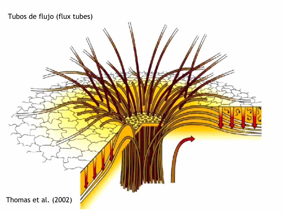
Thomas et al. (2002)
Tubos de flujo (flux tubes)
Flujo Evershed
Normal, a nivel fotosférico: Flujos horizontales predominantemente radiales de la mancha hacia sus alrededores.
Inverso, a nivel cromosférico: El material fluye dirigido hacia la umbra.

Moving Magnetic Features (MMF)
Que son ???Estructuras brillantes que se observan en la moat.Se mueven radialmente. Velocidades de unos cientos de m/s 3 km/s
Tipos • I: Pares bipolares de elementos magnéticos que se mueven juntos 0.5 – 1 km/s.• II: Elementos magnéticos con la misma polaridad que la mancha solar 2 – 3 km/s.• III: Elementos magnéticos con polaridad opuesta a la de la mancha. 2 – 3 km/s.

Contenido
1. Introducción Teórica
1.1 Restauración de imágenes solares 1.2 Estructura fina en regiones activas solares
2. Objetivos
3. Metodología
3.1 Observaciones 3.2 Reducción y tratamiento de los datos 3.3 Análisis y resultados
4. Plan de trabajo

2. Objetivos
Aprender las técnicas de reconstrucción de imagen, Diversidad de Fase (PD) y Multi-Object Multi-Frame Blind Deconvolution (MOMFBD)
• Observar, organizar y reducir las imágenes.
• Implementar el método de MOMFBD para restaurarlas.
• Corregir la serie temporal de efectos de distorsión.
• Hacer un filtrado subsónico.

Entender la dinámica y movimientos propios de regiones solares activas.
• Mapas de velocidad horizontal y divergencias.
• Estudiar la estructura de las zonas alrededor de manchas solares y de la penumbra.
• Estudiar el papel que juega el campo magnético en el comportamiento dinámico del plasma y evolución de estructuras.
2. Objetivos

Contenido
1. Introducción Teórica
1.1 Restauración de imágenes solares 1.2 Estructura fina en regiones activas solares
2. Objetivos
3. Metodología
3.1 Observaciones 3.2 Reducción y tratamiento de los datos 3.3 Análisis y resultados
4. Plan de trabajo

3.1 Observaciones
Se hicieron con la Torre Solar Sueca (SST), La Palma.
Apertura: 1 mDistancia focal primaria: 20.35 mDistancia focal secundaria: 45.8 mEscala de imagen: 4.5 /mmAO de bajo orden

Diversidad de FaseSetup SST

Programa de Observación
International Time Program (ITP)Se pretende observar la evolución y propiedades de estructuras
magnéticas a pequeña escala.
SST
DOT
VTT

Contenido
1. Introducción Teórica
1.1 Restauración de imágenes solares 1.2 Estructura fina en regiones activas solares
2. Objetivos
3. Metodología
3.1 Observaciones 3.2 Reducción y tratamiento de los datos 3.3 Análisis y resultados
4. Plan de trabajo

Restauraciones
G-band

Restauraciones
Imágenes que se usaron:

Corrección de distorsión y Filtrado

Corrección de distorsión y Filtrado

Contenido
1. Introducción Teórica
1.1 Restauración de imágenes solares 1.2 Estructura fina en regiones activas solares
2. Objetivos
3. Metodología
3.1 Observaciones 3.2 Reducción y tratamiento de los datos 3.3 Análisis y resultados
4. Plan de trabajo
3.3 Análisis y Resultados
Movimientos de flujo en la penumbra y sus alrededores
Técnicas de correlación local (LCT) usando algoritmo de November & Simon (1988) para inferir velocidades horizontales.

Mapa de velocidades horizontales


Mapa de velocidades verticales
Gránulos explosivos > 24 m/s Sumideros < -8 m/s

Moats
Flujo estacionario
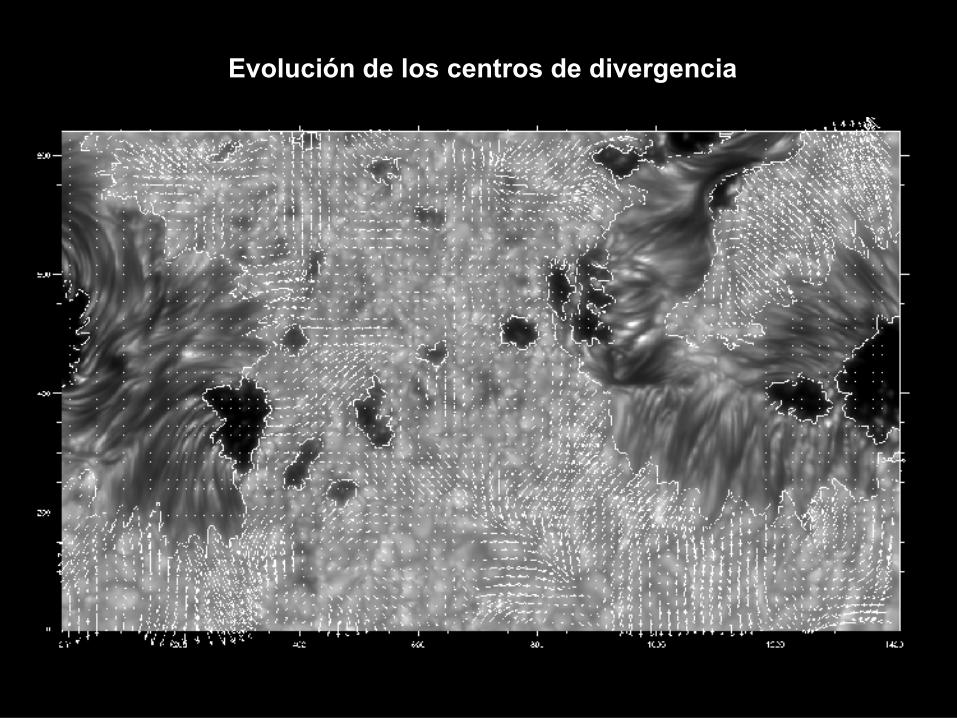
Evolución de los centros de divergencia


Futuros estudios sobre el tema
Analizar más dias de la campaña de 2005
Usar magnetogramas y dopplergramas para inferir las propiedades y comportamiento del campo magnético solar en el campo con la línea neutra.

Contenido
1. Introducción Teórica
1.1 Restauración de imágenes solares 1.2 Estructura fina en regiones activas solares
2. Objetivos
3. Metodología
3.1 Observaciones 3.2 Reducción y tratamiento de los datos 3.3 Análisis y resultados
4. Plan de trabajo
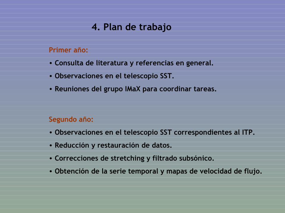
4. Plan de trabajo
Primer año:
• Consulta de literatura y referencias en general.
• Observaciones en el telescopio SST.
• Reuniones del grupo IMaX para coordinar tareas.
Segundo año:
• Observaciones en el telescopio SST correspondientes al ITP.
• Reducción y restauración de datos.
• Correcciones de stretching y filtrado subsónico.
• Obtención de la serie temporal y mapas de velocidad de flujo.
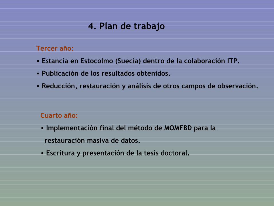
4. Plan de trabajo
Tercer año:
• Estancia en Estocolmo (Suecia) dentro de la colaboración ITP.
• Publicación de los resultados obtenidos.
• Reducción, restauración y análisis de otros campos de observación.
Cuarto año:
• Implementación final del método de MOMFBD para la
restauración masiva de datos.
• Escritura y presentación de la tesis doctoral.


?