Download - ESPECIFICACIONES TÉCNICAS LÍMITES OPERACIÓN
7/28/2019 ESPECIFICACIONES TÉCNICAS LÍMITES OPERACIÓN
http://slidepdf.com/reader/full/especificaciones-tecnicas-limites-operacion 1/30
Rev 0809 3.1-i USNRC HRTD
TABLE OF CONTENTS
3.1.0 Analysis of Technical Specifications – Unit 1 ............................................ 3.1-1
3.1.1 Introduction .......................................................................................... 3.1-3
3.1.2 Technical Specification Requirements ................................................. 3.1-3
3.1.3 Technical Specification Formats .......................................................... 3.1-4
3.1.4 Definitions ............................................................................................ 3.1-6
3.1.4.1 Instrumentation ...................................................................... 3.1-6
3.1.4.2 RCS Leakage ........................................................................ 3.1-6
3.1.4.3 Operability ............................................................................. 3.1-7
3.1.4.4 Operational Modes ................................................................ 3.1-7
3.1.4.5 Shutdown Margin ................................................................... 3.1-7
3.1.5 Use and Application ............................................................................. 3.1-8
3.1.6 Safety Limits and Limiting Safety System Settings .............................. 3.1-8
3.1.6.1 Safety Limits .......................................................................... 3.1-8
3.1.6.2 Limiting Safety System Settings ............................................ 3.1-9
3.1.7 Limiting Conditions For Operation ...................................................... 3.1-10
3.1.8 Technical Requirements Manual ........................................................ 3.1-13
3.1.9 Exercises ........................................................................................... 3.1-14
ATTACHMENTS
ATTACHMENT A - CUSTOM TECHNICAL SPECIFICATION ..................................... 3.1-19
ATTACHMENT B - STANDARD TECHNICAL SPECIFICATION ................................. 3.1-21
ATTACHMENT C - IMPROVED STANDARD TECHNICAL SPECIFICATION ............. 3.1-24
LIST OF FIGURES
Figure 3.1-1 Reactor Core Safety Limits vs. Boundary of Protection ............................ 27

7/28/2019 ESPECIFICACIONES TÉCNICAS LÍMITES OPERACIÓN
http://slidepdf.com/reader/full/especificaciones-tecnicas-limites-operacion 2/30
Rev 0809 3.1-ii USNRC HRTD
This page intentionally blank

7/28/2019 ESPECIFICACIONES TÉCNICAS LÍMITES OPERACIÓN
http://slidepdf.com/reader/full/especificaciones-tecnicas-limites-operacion 3/30
Rev 0809 3.1-1 USNRC HRTD
3.1.0 Analysis of Technical Specifications – Unit 1
Learning Objectives:
1. State the requirements for and briefly describe the categories included in technical
specifications.
2. Demonstrate understanding of the meanings of all defined terms in the technicalspecifications by applying them correctly in operational scenarios.
3. Explain the significance of the safety limits and the limiting safety system settings.
4. When given an initial set of operating conditions, use the format and content of the
technical specifications to identify the applicable section from which to determine the
appropriate plant and/or operator response.

7/28/2019 ESPECIFICACIONES TÉCNICAS LÍMITES OPERACIÓN
http://slidepdf.com/reader/full/especificaciones-tecnicas-limites-operacion 4/30
Rev 0809 3.1-2 USNRC HRTD
This page intentionally blank

7/28/2019 ESPECIFICACIONES TÉCNICAS LÍMITES OPERACIÓN
http://slidepdf.com/reader/full/especificaciones-tecnicas-limites-operacion 5/30
Rev 0809 3.1-3 USNRC HRTD
3.1.1 Introduction
This section is the first of four technical specification sections. It briefly discusses the
requirements for technical specifications, covers the technical specification areas of
definitions and safety limits, and provides general guidance for the use and application of
the limiting conditions for operation (LCOs) and surveillance requirements. Safety limits
are limits upon plant parameters, such as pressure, power, temperature, and flow, which
are necessary to prevent fuel damage or the release of radioactive material. Limiting
conditions for operation identify the required performance levels for safe operation, in termsof equipment operability and limits on certain plant parameters in areas such as reactivity
control and power distribution. The limiting conditions for operation are verified by the
performance of surveillance requirements. Surveillance requirements specify the tests and
functional requirements that equipment must satisfy in order to meet the limiting conditions
for operation.
The significance of the technical specifications is further realized through evaluation of the
bases for the specifications. Each technical specification basis provides information as to
why some limit or requirement has been established and how it contributes to plant safety.
3.1.2 Technical Specification Requirements
Each utility applying for a license to operate a nuclear reactor for commercial purposes
must submit proposed technical specifications with its application to the Nuclear Regulatory
Commission. This is a requirement of the Code of Federal Regulations, Title 10, Chapter l,
Part 50, paragraph 36 (10 CFR 50.36). Each license authorizing operation of a production
facility will then include technical specifications. Technical specifications are derived from
analyses and evaluations included in the Final Safety Analysis Report (FSAR).
10 CFR 50.36 requires that technical specifications include the following categories:
• Safety limits and limiting safety system settings,
• Limiting conditions for operation,• Surveillance requirements,
• Design features, and
• Administrative controls.
Safety limits are limits upon process variables necessary to protect the integrity of certain
physical barriers which guard against the uncontrolled release of radioactivity. The
physical barriers protected by safety limits are the fuel cladding and the reactor coolant
system (RCS).
Limiting safety system settings are settings for automatic protective devices related to
variables having significant safety functions. The protective action from a limiting safetysystem setting corrects the abnormal situation before the safety limits are exceeded.
Limiting conditions for operation are the lowest functional capability or performance levels
of equipment required for safe operation. Each LCO is accompanied by applicability and
action statements. The applicability statement identifies plant conditions during which the
limiting condition for operation applies. The action statements provide requirements that
are invoked when the limiting condition for operation is not met. The lowest allowed

7/28/2019 ESPECIFICACIONES TÉCNICAS LÍMITES OPERACIÓN
http://slidepdf.com/reader/full/especificaciones-tecnicas-limites-operacion 6/30
Rev 0809 3.1-4 USNRC HRTD
performance level of a system is met when either an action statement of the LCO or the
LCO itself is satisfied.
Surveillance requirements are requirements relating to tests, calibrations, and inspections
which ensure that the LCOs are met.
Design features included in technical specifications are those features of the facility which,
if altered or modified, would have a significant effect on safety. Such features include
construction materials and geometric arrangements.
Administrative controls are provisions relating to organization and management,
procedures, recordkeeping, review and audit, and reporting necessary to ensure safe
operation.
The Code of Federal Regulations (10 CFR 50.36a) separately requires technical
specifications for radioactive effluents. Radioactive effluent technical specifications require
compliance with the dose limits of 10 CFR 20, procedures and equipment for the control of
radioactive effluents, and reporting requirements for radioactive releases. These
requirements are addressed in the administrative controls section of the technical
specifications, which is discussed in Section 3.3 of this manual.
Other sections included in technical specifications are (1) definitions and (2) the bases for
the safety limits, limiting safety system settings, LCOs, and surveillance requirements. The
definitions section provides meanings for expressions used throughout the technical
specifications. Bases are summary statements of the bases or reasons for specifications.
Bases are required to be submitted with technical specifications for license application, but
are not required as a part of technical specifications. Nevertheless, they are routinely
included in technical specifications.
3.1.3 Technical Specification Formats
Three different technical specification formats are currently in use at licensed facilities:
custom, standard, and improved standard technical specifications. These formats are
discussed in the following paragraphs.
Originally, technical specifications were prepared on an individual basis for each facility and
thus became known as custom technical specifications. This ad hoc approach resulted in
the issuance of specifications which addressed each of the categories required by 10 CFR
50.36, but also resulted in great diversity in terms of the technical content of specifications
and the interpretations of requirements by licensee staffs and NRC inspectors. Although
custom technical specifications have largely been supplanted by standard formats
throughout the commercial nuclear power industry, they remain in use at a few plants.
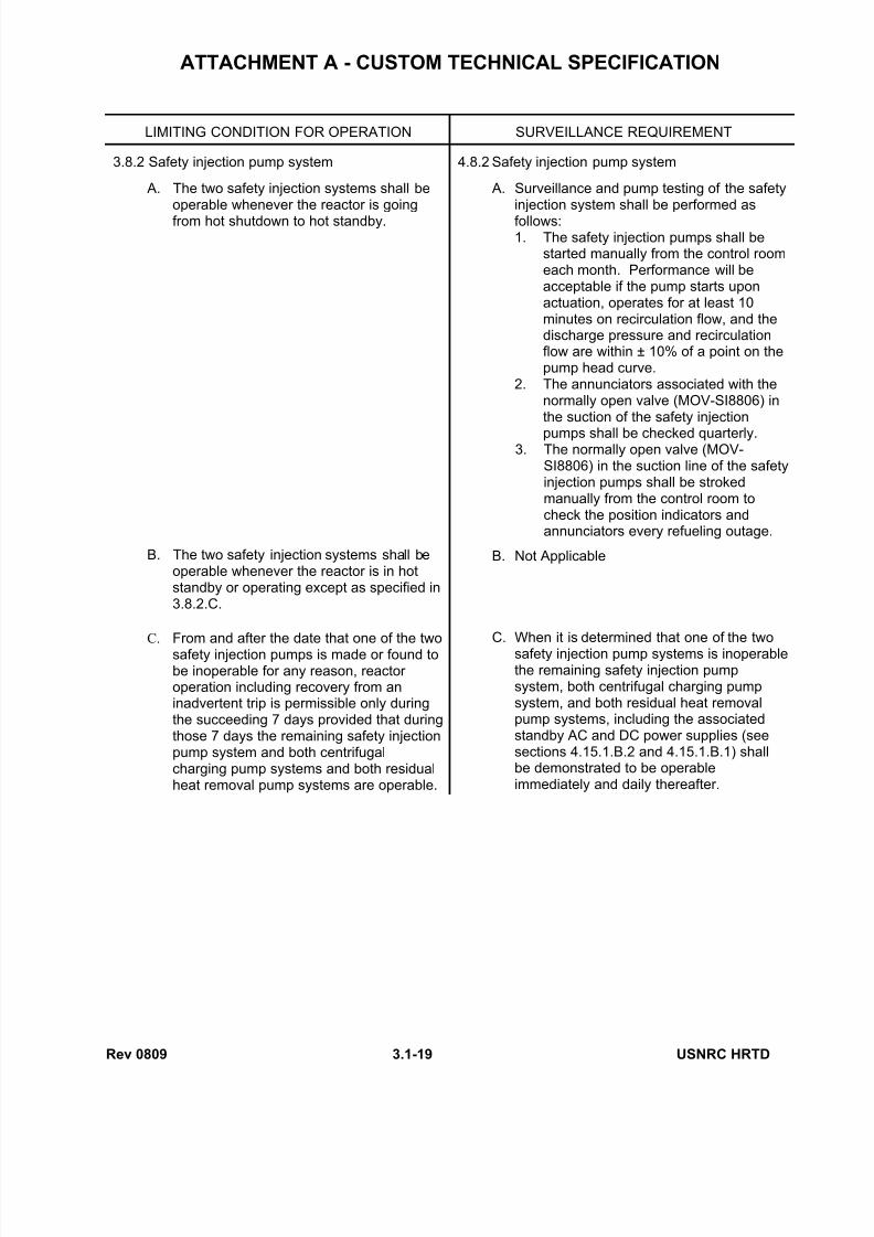
Attachment A illustrates a custom LCO and accompanying surveillance requirements for the safety injection system.
In an effort to provide a systematic approach to technical specification content, the NRC
initiated the Standard Technical Specification Program in the 1970s. This program resulted
in the issuance of standard technical specifications for each nuclear steam supply system
(NSSS) design. For Westinghouse plants, the standard format and content of technical
specifications was provided in NUREG-0452, “Standard Technical Specifications for
Westinghouse Pressurized Water Reactors” (revised several times). The standard
7/28/2019 ESPECIFICACIONES TÉCNICAS LÍMITES OPERACIÓN
http://slidepdf.com/reader/full/especificaciones-tecnicas-limites-operacion 7/30
Rev 0809 3.1-5 USNRC HRTD
technical specifications were used as the template for the technical specifications of newly
licensed plants, and many licensees converted their custom technical specifications to the
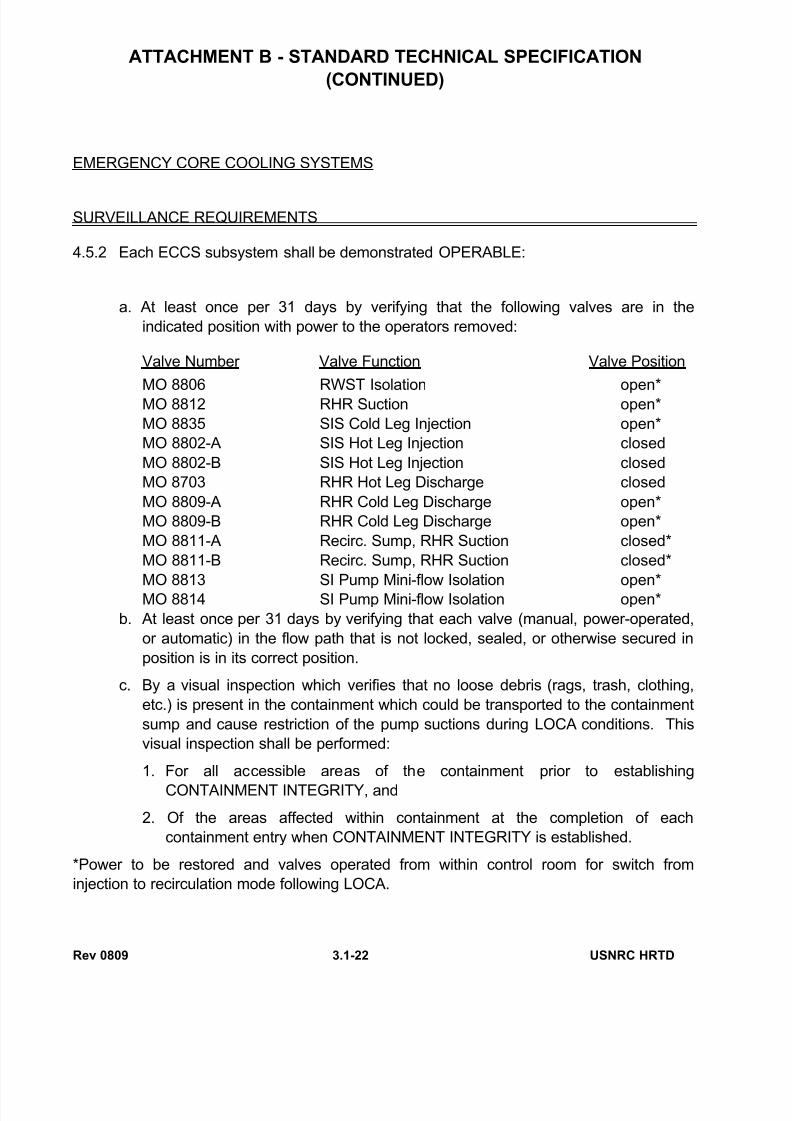
standard format as well. Attachment B illustrates a standard LCO and accompanying
surveillance requirements for the emergency core cooling systems (ECCSs).
Over the last few decades there has been a trend toward including in technical
specifications not only those requirements derived from the analyses and evaluations in the
FSAR, but also essentially all other NRC requirements governing reactor operation. This
extensive use of technical specifications has been due in part to a lack of well-definedcriteria for what should be included in technical specifications. This practice has
contributed to the volume of technical specifications, a large increase in the number of
technical specification amendment applications, and a potentially adverse impact on safety.
To address these issues, in the 1980s the nuclear industry and the NRC began studying
whether the existing technical specification requirements needed improvement. This effort
culminated in 1993 with the issuance of revised criteria for the contents of technical
specifications, published in the “Final Policy Statement on Technical Specification
Improvements for Nuclear Power Reactors.” The final policy statement was incorporated
into 10 CFR 50.36 in 1995 and reads as follows:
(ii) A technical specification limiting condition for operation of a nuclear reactor must be
established for each item meeting one or more of the following criteria:
(A) Criterion 1. Installed instrumentation that is used to detect, and indicate in
the control room, a significant abnormal degradation of the reactor coolant
pressure boundary.
(B) Criterion 2 . A process variable, design feature, or operating restriction that is
an initial condition of a design basis accident or transient analysis that either
assumes the failure of or presents a challenge to the integrity of a fission product
barrier.(C) Criterion 3. A structure, system, or component that is part of the primary
success path and which functions or actuates to mitigate a design basis accident
or transient that either assumes the failure of or presents a challenge to the
integrity of a fission product barrier.
(D) Criterion 4. A structure, system, or component which operating experience or
probabilistic risk assessment has shown to be significant to public health and
safety.
Based on the criteria of the final policy statement (and the preceding interim criteria),
improved standard technical specifications have been developed for each NSSS design.These improved standard specifications are the result of extensive public technical
meetings and discussions between the NRC staff and various nuclear power plant
licensees, NSSS owners groups, NSSS vendors, and the Nuclear Energy Institute. For
Westinghouse pants, the improved standard technical specifications are provided in
NUREG-1431, “Standard Technical Specifications, Westinghouse Plants,” originally issued
in 1992 and first revised in 1995. Attachment C illustrates an improved standard LCO and
accompanying surveillance requirements for the ECCSs.
7/28/2019 ESPECIFICACIONES TÉCNICAS LÍMITES OPERACIÓN
http://slidepdf.com/reader/full/especificaciones-tecnicas-limites-operacion 8/30
Rev 0809 3.1-6 USNRC HRTD
Licensees are encouraged to upgrade their technical specifications consistent with the
criteria of the final policy statement and conforming to the improved standard technical
specifications. The NRC continues to place the highest priority on requests for complete
conversions to the improved standard technical specifications. Several licensees have
already converted their technical specifications, and it is expected that ultimately most
specifications will conform to the improved standard format. Technical specifications
conforming to the improved standard technical specifications of NUREG-1431 have been
developed for TTC Unit 2 (the Westinghouse simulator) and are used to illustrate technicalspecification requirements and usage in this manual.
3.1.4 Definitions
To ensure a uniform interpretation of technical specifications, selected terms are defined in
the definitions section. The definitions comprise a subsection of the use and application
section of the specifications. Defined terms used throughout technical specifications are
identified by upper-case type (a practice also observed in the technical specification
sections of this manual). Selected definitions are discussed in the following paragraphs.
3.1.4.1 Instrumentation
The proper measurement of process variables such as pressurizer pressure, RCS average
temperature (Tavg), RCS differential temperature ( ΔT), and nuclear power is verified by
three methods:
• CHANNEL CHECK: the qualitative assessment of channel behavior during operation
by observation.
• CHANNEL OPERATIONAL TEST: the injection of a simulated or actual signal into
the channel as close to the sensor as practicable to verify the OPERABILITY of the
required alarm, interlock, display, and trip functions.
• CHANNEL CALIBRATION: the adjustment, as necessary, of the channel output
such that it responds within the required range and accuracy to known values of
input.
Control room operators perform CHANNEL CHECKS during routine observation of control
board indications. For instance, the indications of all four RCS Tavg meters are compared to
each other to ensure agreement among them. If a deviation exists, instrumentation and
control technicians then perform a CHANNEL OPERATIONAL TEST on the instrument
showing the deviation. CHANNEL OPERATIONAL TESTS are performed on all channels
which measure process variables at routine intervals and when deviations are identified.
Adjustments of trip, interlock, and alarm setpoints are made to ensure that the setpoints are
within the required range of accuracy. A CHANNEL CALIBRATION is performed to ensurethat a channel responds properly to a known input. During a channel calibration, the
channel’s sensor and bistables are adjusted to provide accurate and proper responses.
3.1.4.2 RCS Leakage
Because of the potential radiological and equipment problems associated with RCS
LEAKAGE, it is important to understand the types of LEAKAGE. These include:
• Identified LEAKAGE,
7/28/2019 ESPECIFICACIONES TÉCNICAS LÍMITES OPERACIÓN
http://slidepdf.com/reader/full/especificaciones-tecnicas-limites-operacion 9/30
Rev 0809 3.1-7 USNRC HRTD
• Unidentified LEAKAGE, and
• Pressure boundary LEAKAGE.
Identified LEAKAGE is LEAKAGE:
Such as that from pump seals or valve packing, that is captured and conducted to
collection systems or a sump or collecting tank;
Into the containment atmosphere from sources that are both specifically located and
known either not to interfere with the operation of leakage detection systems or not
to be pressure boundary LEAKAGE; or
From the RCS through a steam generator to the secondary system.
Pressure boundary LEAKAGE is LEAKAGE (except steam generator tube LEAKAGE)
through a nonisolable fault in an RCS component body, pipe wall, or vessel wall.
Unidentified LEAKAGE is leakage which is not identified LEAKAGE. When LEAKAGE from
the RCS is first suspected or discovered, it is normally categorized as unidentified
LEAKAGE.
Once the source of LEAKAGE is determined, it can be recategorized as either identified or pressure boundary LEAKAGE.
3.1.4.3 Operability
Many limiting conditions for operation for specific equipment require systems or
components to be OPERABLE. The designation OPERABLE/OPERABILITY stipulates
that a system, subsystem, train, component, or device is capable of performing its specified
safety functions, and that all necessary controls, power, and auxiliary equipment required
for the system, subsystem, train, component, or device to perform its specified safety
functions are also capable of performing their related support functions. For instance, a
centrifugal charging pump that starts and delivers flow to the RCS could not be consideredOPERABLE if its lubricating oil or cooling water support system is out of service.
3.1.4.4 Operational Modes
Operation of the plant is divided into six operational MODES. An operational MODE
corresponds to any one inclusive combination of core reactivity condition, power level,
average reactor coolant temperature, and reactor vessel head closure bolt tensioning, as
specified in technical specification Table 1.1-1, with fuel in the reactor vessel.
Operational MODES are used to identify plant conditions during which certain limiting
conditions for operation apply.
3.1.4.5 Shutdown Margin
SDM shall be the instantaneous amount of reactivity by which the reactor is subcritical or
would be subcritical from its present condition assuming:
a. All rod cluster control assemblies (RCCAs) are fully inserted except for the single
RCCA of highest reactivity worth, which is assumed to be fully withdrawn. However,
with all RCCAs verified fully inserted by two independent means, it is not necessary
to account for a stuck RCCA in the SDM calculation. With any RCCA not capable of

7/28/2019 ESPECIFICACIONES TÉCNICAS LÍMITES OPERACIÓN
http://slidepdf.com/reader/full/especificaciones-tecnicas-limites-operacion 10/30
Rev 0809 3.1-8 USNRC HRTD
being fully inserted, the reactivity worth of the RCCA must be accounted for in the
determination of SDM, and
b. In MODES 1 and 2, the fuel and moderator temperatures are changed to the
nominal zero power design level.
3.1.5 Use and Application
Section 1.0, Use and Application, contains definitions (as in the examples above) and also
gives several examples of how to use technical specifications.
Section 1.2 explains the use of the logical connectors AND and OR. Levels of logic are
identified by the placement (or nesting) of the logical connectors.
Section 1.3 establishes the completion time convention and gives several examples of
completion time application. The completion time extension associated with subsequent
inoperability is defined here.
Section 1.4 defines the proper use and application of the frequency requirements and gives
several examples.
It is not the intention of this manual to repeat these sections of technical specifications.
The student should read section 1.0 and work through the examples.
3.1.6 Safety Limits and Limiting Safety System Settings
3.1.6.1 Safety Limits
Safety limits are established to prevent the uncontrolled release of radioactivity by
protecting the integrity of fission product barriers during normal operation and anticipated
operational occurrences.
The safety limits on the reactor core address the first barrier to the release of radioactive
material, the fuel cladding. The possibility of fuel cladding damage is prevented by
observing operating limits that preclude violation of the following fuel design criteria:
There must be at least 95% probability at a 95% confidence level (the 95/95 departure from
nucleate boiling [DNB] criterion) that the hot fuel rod in the core does not experience DNB;
and the hot fuel pellet in the core must not experience centerline fuel melting.
The proper functioning of the Reactor Protection System (RPS) and steam generator safety
valves prevents violation of the reactor core safety limits.
7/28/2019 ESPECIFICACIONES TÉCNICAS LÍMITES OPERACIÓN
http://slidepdf.com/reader/full/especificaciones-tecnicas-limites-operacion 11/30
Rev 0809 3.1-9 USNRC HRTD
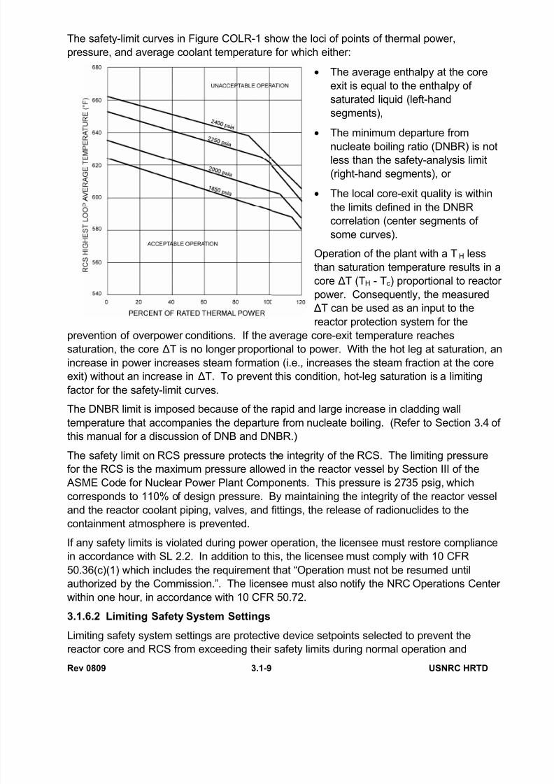
The safety-limit curves in Figure COLR-1 show the loci of points of thermal power,
pressure, and average coolant temperature for which either:
• The average enthalpy at the core
exit is equal to the enthalpy of
saturated liquid (left-hand
segments),
•
The minimum departure fromnucleate boiling ratio (DNBR) is not
less than the safety-analysis limit
(right-hand segments), or
• The local core-exit quality is within
the limits defined in the DNBR
correlation (center segments of
some curves).
Operation of the plant with a TH less
than saturation temperature results in a
core ΔT (TH - Tc) proportional to reactor
power. Consequently, the measured
ΔT can be used as an input to the
reactor protection system for the
prevention of overpower conditions. If the average core-exit temperature reaches
saturation, the core ΔT is no longer proportional to power. With the hot leg at saturation, an
increase in power increases steam formation (i.e., increases the steam fraction at the core
exit) without an increase in ΔT. To prevent this condition, hot-leg saturation is a limiting
factor for the safety-limit curves.
The DNBR limit is imposed because of the rapid and large increase in cladding walltemperature that accompanies the departure from nucleate boiling. (Refer to Section 3.4 of
this manual for a discussion of DNB and DNBR.)
The safety limit on RCS pressure protects the integrity of the RCS. The limiting pressure
for the RCS is the maximum pressure allowed in the reactor vessel by Section III of the
ASME Code for Nuclear Power Plant Components. This pressure is 2735 psig, which
corresponds to 110% of design pressure. By maintaining the integrity of the reactor vessel
and the reactor coolant piping, valves, and fittings, the release of radionuclides to the
containment atmosphere is prevented.
If any safety limits is violated during power operation, the licensee must restore compliance
in accordance with SL 2.2. In addition to this, the licensee must comply with 10 CFR
50.36(c)(1) which includes the requirement that “Operation must not be resumed until
authorized by the Commission.”. The licensee must also notify the NRC Operations Center
within one hour, in accordance with 10 CFR 50.72.
3.1.6.2 Limiting Safety System Settings
Limiting safety system settings are protective device setpoints selected to prevent the
reactor core and RCS from exceeding their safety limits during normal operation and
7/28/2019 ESPECIFICACIONES TÉCNICAS LÍMITES OPERACIÓN
http://slidepdf.com/reader/full/especificaciones-tecnicas-limites-operacion 12/30
Rev 0809 3.1-10 USNRC HRTD
anticipated operational occurrences (Condition I and II events). In standard technical
specifications (conforming to NUREG-0452), the limiting safety system settings are listed in
a separate section. In improved standard technical specifications (conforming to NUREG-
1431), the limiting safety system settings are included as the reactor trip system (RTS)
setpoints in the RTS instrumentation LCO. This LCO is discussed in Section 3.2 of this
manual.
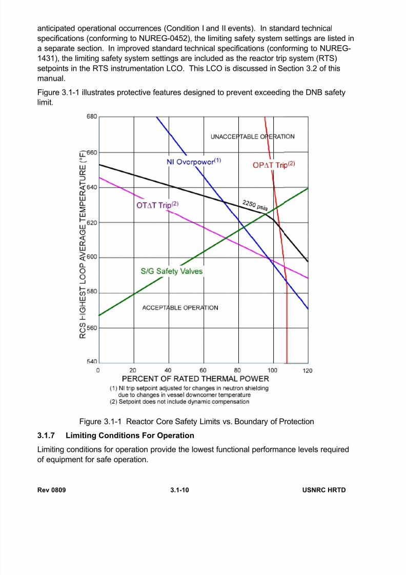
Figure 3.1-1 illustrates protective features designed to prevent exceeding the DNB safety
limit.
Figure 3.1-1 Reactor Core Safety Limits vs. Boundary of Protection
3.1.7 Limiting Conditions For Operation
Limiting conditions for operation provide the lowest functional performance levels required
of equipment for safe operation.
7/28/2019 ESPECIFICACIONES TÉCNICAS LÍMITES OPERACIÓN
http://slidepdf.com/reader/full/especificaciones-tecnicas-limites-operacion 13/30
Rev 0809 3.1-11 USNRC HRTD
Attachment A is an example of a custom technical specification LCO. Note that the
statement of the LCO in the left-hand column specifies the extent of system OPERABILITY
and the operational MODES in which the LCO is applicable. Note also that some of the
left-hand column paragraphs provide additional requirements and time limits for action in
the event that the LCO is not completely satisfied. The surveillance requirements
applicable to each paragraph of the LCO are provided in the right-hand column. The bases
for this LCO (not shown in Attachment A) and other ECCS LCOs are provided at the end of
the ECCS section of the technical specifications. Attachment B is an example of a standard technical specification LCO. The statement of
the LCO, the applicability requirements, and the actions to be taken when the LCO is not
met are provided in a more straightforward manner. This format for LCO presentation is
consistently maintained throughout the technical specifications. The LCO and its
associated applicability and action statements are immediately followed by the
surveillances required to ensure that the LCO is satisfied (only the first page of surveillance
requirements is shown in Attachment B). The bases for this LCO (also shown in
Attachment B) and other ECCS LCOs are provided in the ECCS bases section of the
specifications.
The LCO section of standard technical specifications (conforming to the NUREG-0452
format) is typically divided into the following subsections:
• Applicability,
• Reactivity control systems,
• Power distribution limits,
• Instrumentation,
• Reactor coolant system,
• Emergency core cooling systems,
• Containment systems,
• Plant systems,
• Electrical power systems,
• Refueling operations,
• Special test exceptions,
• Radioactive effluents, and
• Radiological environmental monitoring.
The bases section of the specifications immediately follows the last LCO. The bases
section is divided into subsections consistent with those listed above for the LCOs.
Attachment C is an example of an improved standard technical specification LCO. The
LCO and applicability statements are similar to those of standard technical specification
LCOs, but the actions required when the LCO is not met and the completion times for those
7/28/2019 ESPECIFICACIONES TÉCNICAS LÍMITES OPERACIÓN
http://slidepdf.com/reader/full/especificaciones-tecnicas-limites-operacion 14/30
Rev 0809 3.1-12 USNRC HRTD
actions are presented in tabular form. The surveillance requirements, which immediately
follow the LCO, are also presented in tabular form.
The use and application section of the technical specifications provides guidance for the
interpretation of the required actions and completion times included in the LCO action
tables, and also for the frequencies with which required surveillances must be performed.
The LCO section of improved standard technical specifications (conforming to the NUREG-
1431 format) is typically divided into the following subsections:
• Applicability,
• Reactivity control systems,
• Power distribution limits,
• Instrumentation,
• Reactor coolant system,
• Emergency core cooling systems,
•
Containment systems,• Plant systems,
• Electrical power systems, and
• Refueling operations.
These LCO groupings are similar to those of standard technical specifications. In improved
standard technical specifications, special test exceptions are incorporated into the reactivity
control systems section, and requirements for radioactive effluents and radiological
environmental monitoring are incorporated into programs required by the administrative
controls section.
The bases section of improved standard technical specifications is divided into subsections
consistent with the list above and is provided in a separate specification volume. The basis
for a particular LCO provides information in the following areas:
• Background information on the subject system, component, or parameter;
• How the LCO relates to applicable safety analyses in the FSAR;
• The contribution to unit safety provided by compliance with the LCO;
• The conditions in which the LCO applies;
• Reasons for the required actions to be taken when the LCO is not met;
• Reasons for the surveillance requirements which verify compliance with the LCO;
and
• Referenced documents.
This information is generally much more extensive and far more indicative of the LCO’s
relationship to safety analyses than that provided by the superseded standard technical
specifications.
7/28/2019 ESPECIFICACIONES TÉCNICAS LÍMITES OPERACIÓN
http://slidepdf.com/reader/full/especificaciones-tecnicas-limites-operacion 15/30
Rev 0809 3.1-13 USNRC HRTD
Detailed discussions of the LCOs in each LCO subsection of the technical specifications
are provided in Sections 3.2, 3.3, and 3.4 of this manual.
3.1.8 Technical Requirements Manual
Many LCOs which had been included in standard technical specifications (conforming to
NUREG-0452) do not meet the updated criteria for inclusion in technical specifications and
are thus not included in improved standard technical specifications (conforming to NUREG-
1431). Many of these LCOs and their associated action and surveillance requirements
have been relocated to the Technical Requirements Manual. These requirements are
implemented in the same fashion as technical specifications, but they are treated as plant
procedures. Violations of technical requirement action or surveillance requirements are not
reportable as conditions prohibited by technical specifications per 10 CFR 50.72 or 10 CFR
50.73. Also, power reductions or plant shutdowns required to comply with technical
requirement action statements are not reportable per 10 CFR 50.72 or 10 CFR 50.73.
Violations of technical requirement action or surveillance requirements are treated as plant
procedure violations by licensees and may be cited as such by NRC inspectors.

7/28/2019 ESPECIFICACIONES TÉCNICAS LÍMITES OPERACIÓN
http://slidepdf.com/reader/full/especificaciones-tecnicas-limites-operacion 16/30
Rev 0809 3.1-14 USNRC HRTD
3.1.9 Exercises
Exercise 1
The unit is operating at 95% power. On May 15 at 1:00 p.m., accumulator A
becomes inoperable because its boron concentration is not within limits. On May 17
at 2:00 p.m., accumulator D becomes inoperable for the same reason. On May 17
at 4:00 p.m., the boron concentration of accumulator A is restored to within limits(i.e., the operability of accumulator A is restored). See LCO 3.5.1.
1. At the time the first accumulator becomes inoperable, what condition is entered?
2. At the time the second accumulator becomes inoperable, what condition(s) apply?
3. When the first inoperable accumulator is restored to operable status, what
condition(s) apply?
4. How long can accumulator D remain inoperable before a condition requiring a unit
shutdown is entered?
Exercise 2
The unit is in Mode 1. The following sequence of events occurs (see LCO 3.8.1):
June 1, 8:00 a.m. Diesel generator B becomes inoperable.
June 3, 8:00 a.m. The offsite circuit which supplies power to ESF bus A becomes
inoperable. The diesel generator remains inoperable.
June 3, 4:00 p.m. Diesel generator B is restored to operable status. The offsite circuit
remains inoperable.
June 5, 8:00 a.m. Diesel generator A becomes inoperable. The offsite circuit remains
inoperable. Assume the bus remains energized through the unitauxiliary transformer.
June 5, 2:00 p.m. The inoperable offsite circuit is restored to operable status. Diesel
generator A remains inoperable.
1. State the conditions which apply at each interval.
2. How long can diesel generator A remain inoperable before a condition requiring a
unit shutdown is entered?
Exercise 3On May 8 at 6:00 p.m., with the unit at 90% power, a power range neutron flux channel
becomes inoperable, necessitating the performance of Surveillance Requirement 3.2.4.2
for verification of the quadrant power tilt ratio (see LCO 3.2.4). The first two verifications
are made at the following times: May 9 at 8:00 a. m., and May 9 at 10:00 p.m. Does either
of these violate the specified surveillance Frequency?
7/28/2019 ESPECIFICACIONES TÉCNICAS LÍMITES OPERACIÓN
http://slidepdf.com/reader/full/especificaciones-tecnicas-limites-operacion 17/30
Rev 0809 3.1-15 USNRC HRTD
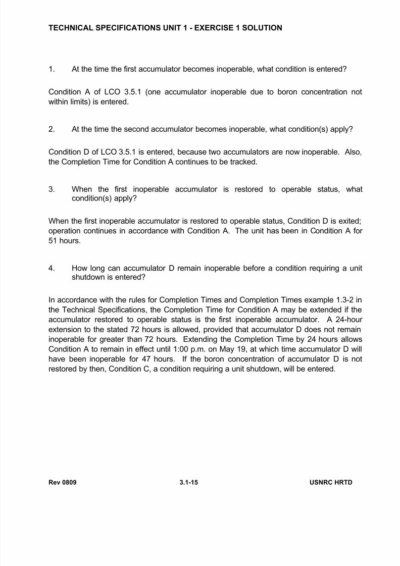
TECHNICAL SPECIFICATIONS UNIT 1 - EXERCISE 1 SOLUTION
1. At the time the first accumulator becomes inoperable, what condition is entered?
Condition A of LCO 3.5.1 (one accumulator inoperable due to boron concentration not
within limits) is entered.
2. At the time the second accumulator becomes inoperable, what condition(s) apply?
Condition D of LCO 3.5.1 is entered, because two accumulators are now inoperable. Also,
the Completion Time for Condition A continues to be tracked.
3. When the first inoperable accumulator is restored to operable status, what
condition(s) apply?
When the first inoperable accumulator is restored to operable status, Condition D is exited;
operation continues in accordance with Condition A. The unit has been in Condition A for
51 hours.
4. How long can accumulator D remain inoperable before a condition requiring a unitshutdown is entered?
In accordance with the rules for Completion Times and Completion Times example 1.3-2 inthe Technical Specifications, the Completion Time for Condition A may be extended if the
accumulator restored to operable status is the first inoperable accumulator. A 24-hour
extension to the stated 72 hours is allowed, provided that accumulator D does not remain
inoperable for greater than 72 hours. Extending the Completion Time by 24 hours allows
Condition A to remain in effect until 1:00 p.m. on May 19, at which time accumulator D will
have been inoperable for 47 hours. If the boron concentration of accumulator D is not
restored by then, Condition C, a condition requiring a unit shutdown, will be entered.

7/28/2019 ESPECIFICACIONES TÉCNICAS LÍMITES OPERACIÓN
http://slidepdf.com/reader/full/especificaciones-tecnicas-limites-operacion 18/30
Rev 0809 3.1-16 USNRC HRTD
TECHNICAL SPECIFICATIONS UNIT 1 - EXERCISE 2 SOLUTION
1. State the conditions which apply at each interval.
June 1, 8:00 a.m. Condition B is entered. Completion Time for restoration of operablestatus (Required Action B.4): 72 hours. (Other required actions apply.)
June 3, 8:00 a.m. Conditions A & D are entered. Completion Time for restoration of
offsite circuit operability (Required Action A.3): 72 hours. (Other
required actions for Condition A apply.) Completion Time for
restoration of either diesel generator or offsite circuit (Required Action
D.1 or D.2): 12 hours. Condition B still applies; the unit has been in
Condition B for 48 hours.
June 3, 4:00 p.m. Conditions B & D are exited (each within the specified Completion
Time). Condition A still applies; the unit has been in Condition A for 8
hours.
June 5, 8:00 a.m. Conditions B & D are reentered, with Completion Times of 72 hours
and 12 hours, respectively. Condition A still applies; the unit has been
in Condition A for 48 hours. Since the bus still has an AC power
source (the unit auxiliary transformer), it is not necessary to declare the
bus inoperable (i.e. apply actions of LCO 3.8.9). A bus is operable if itis energized, even if it has neither TS required source.
June 5, 2:00 p.m. Conditions A & D are exited (each within the specified Completion
Time). Condition B still applies; the unit has been in Condition B for 6
hours.
2. How long can diesel generator A remain inoperable before a condition requiring a
unit shutdown is entered?
Diesel generator A can remain inoperable until 8:00 a.m. on June 8, when its 72 hour
completion time expires. At that time, condition G is entered.

7/28/2019 ESPECIFICACIONES TÉCNICAS LÍMITES OPERACIÓN
http://slidepdf.com/reader/full/especificaciones-tecnicas-limites-operacion 19/30
Rev 0809 3.1-17 USNRC HRTD
TECHNICAL SPECIFICATIONS UNIT 1 - EXERCISE 3 SOLUTION
Does either of these violate the specified surveillance Frequency?
No. In accordance with Frequency example 1.4-3 in the Technical Specifications, the 25%extension can be applied to the first performance, and to subsequent intervals. This allows
a 15 hour interval. The Frequency is satisfied for both performances.

7/28/2019 ESPECIFICACIONES TÉCNICAS LÍMITES OPERACIÓN
http://slidepdf.com/reader/full/especificaciones-tecnicas-limites-operacion 20/30
Rev 0809 3.1-18 USNRC HRTD
This page intentionally blank
7/28/2019 ESPECIFICACIONES TÉCNICAS LÍMITES OPERACIÓN
http://slidepdf.com/reader/full/especificaciones-tecnicas-limites-operacion 21/30
Rev 0809 3.1-19 USNRC HRTD
ATTACHMENT A - CUSTOM TECHNICAL SPECIFICATION
LIMITING CONDITION FOR OPERATION SURVEILLANCE REQUIREMENT
3.8.2 Safety injection pump system
A. The two safety injection systems shall beoperable whenever the reactor is going
from hot shutdown to hot standby.
B. The two safety injection systems shall beoperable whenever the reactor is in hotstandby or operating except as specified in3.8.2.C.
C. From and after the date that one of the two
safety injection pumps is made or found tobe inoperable for any reason, reactor operation including recovery from aninadvertent trip is permissible only duringthe succeeding 7 days provided that duringthose 7 days the remaining safety injectionpump system and both centrifugalcharging pump systems and both residualheat removal pump systems are operable.
4.8.2 Safety injection pump system
A. Surveillance and pump testing of the safetyinjection system shall be performed as
follows:1. The safety injection pumps shall be
started manually from the control roomeach month. Performance will beacceptable if the pump starts uponactuation, operates for at least 10minutes on recirculation flow, and thedischarge pressure and recirculationflow are within ± 10% of a point on thepump head curve.
2. The annunciators associated with thenormally open valve (MOV-SI8806) inthe suction of the safety injection
pumps shall be checked quarterly.3. The normally open valve (MOV-
SI8806) in the suction line of the safetyinjection pumps shall be strokedmanually from the control room tocheck the position indicators andannunciators every refueling outage.
B. Not Applicable
C. When it is determined that one of the two
safety injection pump systems is inoperablethe remaining safety injection pumpsystem, both centrifugal charging pumpsystem, and both residual heat removalpump systems, including the associatedstandby AC and DC power supplies (seesections 4.15.1.B.2 and 4.15.1.B.1) shallbe demonstrated to be operableimmediately and daily thereafter.

7/28/2019 ESPECIFICACIONES TÉCNICAS LÍMITES OPERACIÓN
http://slidepdf.com/reader/full/especificaciones-tecnicas-limites-operacion 22/30
Rev 0809 3.1-20 USNRC HRTD
ATTACHMENT A - CUSTOM TECHNICAL SPECIFICATION (CONTINUED)
LIMITING CONDITION FOR OPERATION SURVEILLANCE REQUIREMENT
3.8.2 D. If these conditions cannot be met the
reactor shall be brought to the hot
shutdown condition within four hours.
After a maximum of 48 hours in the hotshutdown condition, if the system is not
operable the reactor shall be brought to
the cold shutdown condition within 12
hours.
4.8.2 D. Not Applicable

7/28/2019 ESPECIFICACIONES TÉCNICAS LÍMITES OPERACIÓN
http://slidepdf.com/reader/full/especificaciones-tecnicas-limites-operacion 23/30
Rev 0809 3.1-21 USNRC HRTD
ATTACHMENT B - STANDARD TECHNICAL SPECIFICATION
EMERGENCY CORE COOLING SYSTEMS
ECCS SUBSYSTEMS - Tavg ≥ 350°F
LIMITING CONDITION FOR OPERATION
3.5.2 Two independent ECCS subsystems shall be OPERABLE with each subsystem
comprised of:
a. One OPERABLE centrifugal charging pump,
b. One OPERABLE safety injection pump,
c. One OPERABLE residual heat removal heat exchanger,
d. One OPERABLE residual heat removal pump, and
e. An OPERABLE flow path capable of taking suction from the refueling water
storage tank on a safety injection signal and transferring suction to the
containment sump during the recirculation phase of operation.
APPLICABILITY: MODES 1, 2, and 3.
ACTION:
a. With one ECCS subsystem inoperable, restore the inoperable subsystem to
OPERABLE status within 72 hours or be in HOT SHUTDOWN within the next 12
hours.
b. In the event the ECCS is actuated and injects water into the Reactor Coolant
System, a Special Report shall be prepared and submitted to the Commission
pursuant to Specification 6.9.2 within 90 days describing the circumstances of theactuation and the total accumulated actuation cycles to date.
7/28/2019 ESPECIFICACIONES TÉCNICAS LÍMITES OPERACIÓN
http://slidepdf.com/reader/full/especificaciones-tecnicas-limites-operacion 24/30
Rev 0809 3.1-22 USNRC HRTD
ATTACHMENT B - STANDARD TECHNICAL SPECIFICATION
(CONTINUED)
EMERGENCY CORE COOLING SYSTEMS
SURVEILLANCE REQUIREMENTS
4.5.2 Each ECCS subsystem shall be demonstrated OPERABLE:
a. At least once per 31 days by verifying that the following valves are in the
indicated position with power to the operators removed:
Valve Number Valve Function Valve Position
MO 8806MO 8812
MO 8835
MO 8802-A
MO 8802-B
MO 8703
MO 8809-A
MO 8809-B
MO 8811-A
MO 8811-B
MO 8813
MO 8814
RWST IsolationRHR Suction
SIS Cold Leg Injection
SIS Hot Leg Injection
SIS Hot Leg Injection
RHR Hot Leg Discharge
RHR Cold Leg Discharge
RHR Cold Leg Discharge
Recirc. Sump, RHR Suction
Recirc. Sump, RHR Suction
SI Pump Mini-flow Isolation
SI Pump Mini-flow Isolation
open*open*
open*
closed
closed
closed
open*
open*
closed*
closed*
open*
open*
b. At least once per 31 days by verifying that each valve (manual, power-operated,
or automatic) in the flow path that is not locked, sealed, or otherwise secured in
position is in its correct position.
c. By a visual inspection which verifies that no loose debris (rags, trash, clothing,
etc.) is present in the containment which could be transported to the containment
sump and cause restriction of the pump suctions during LOCA conditions. This
visual inspection shall be performed:
1. For all accessible areas of the containment prior to establishing
CONTAINMENT INTEGRITY, and
2. Of the areas affected within containment at the completion of each
containment entry when CONTAINMENT INTEGRITY is established.
*Power to be restored and valves operated from within control room for switch from
injection to recirculation mode following LOCA.

7/28/2019 ESPECIFICACIONES TÉCNICAS LÍMITES OPERACIÓN
http://slidepdf.com/reader/full/especificaciones-tecnicas-limites-operacion 25/30
Rev 0809 3.1-23 USNRC HRTD
ATTACHMENT B - STANDARD TECHNICAL SPECIFICATION
(CONTINUED)
3/4.5 EMERGENCY CORE COOLING SYSTEMS (ECCS)
BASES
3/4.5.2 and 3/4.5.3.1 ECCS SUBSYSTEMS
The OPERABILITY of two independent ECCS subsystems ensures that sufficientemergency core cooling capability will be available in the event of a LOCA assuming the
loss of one subsystem through any single failure consideration. Either subsystem
operating in conjunction with the accumulators is capable of supplying sufficient core
cooling to limit the peak cladding temperatures within acceptable limits for all postulated
break sizes ranging from the double ended break of the largest RCS cold leg pipe
downward. In addition, each ECCS subsystem provides long term core cooling capability
in the recirculation mode during the accident recovery period.
With the RCS temperature below 350°F, one OPERABLE ECCS subsystem is
acceptable without a single failure consideration on the basis of the stable reactivity
condition of the reactor and the limited core cooling requirements.
The Surveillance Requirements, which are provided to ensure the OPERABILITY of
each component, ensure that, at a minimum, the assumption used in the safety analysis
are met and that subsystem OPERABILITY is maintained. The safety analyses make
assumptions with respect to: (1) both the maximum and minimum total system resistance
and (2) both the maximum and minimum branch injection line resistance. These
resistances, in conjunction with the ranges of potential pump performance, are used to
calculate the maximum and minimum ECCS flow assumed in the safety analysis.
The maximum and minimum flow Surveillance Requirements in conjunction with the
maximum and minimum pump performance curves ensure that the assumptions of totalsystem resistance and the distribution of that system resistance among the various paths
are met.
The maximum total pump flow Surveillance Requirements ensure that the pump
runout limits of 560 gpm for the centrifugal charging pumps and 675 gpm for the safety
injection pumps are not exceeded.
The Surveillance Requirements for the maximum difference between the maximum and
minimum individual injection line flows ensure that the minimum individual injection line
resistance assumed for the spilling line following a LOCA is met.
The safety analyses are performed assuming the miniflow recirculation lines for the
ECCS subsystems associated with the centrifugal charging and safety injection pumps are
open. The flow balancing test is, therefore, performed with these miniflow recirculation
lines open.
The surveillance flow and differential pressure requirements are the Safety Analysis
Limits and do not include instrument uncertainties.

7/28/2019 ESPECIFICACIONES TÉCNICAS LÍMITES OPERACIÓN
http://slidepdf.com/reader/full/especificaciones-tecnicas-limites-operacion 26/30
Rev 0809 3.1-24 USNRC HRTD
ATTACHMENT C - IMPROVED STANDARD TECHNICAL SPECIFICATION
3.5 EMERGENCY CORE COOLING SYSTEMS (ECCS)
3.5.2 ECCS - Operating
LCO 3.5.2 Two ECCS trains shall be OPERABLE.
--------------------------------------------NOTES-------------------------------------------
1. In MODE 3, both safety injection (SI) pump flow paths may be isolatedby closing the isolation valves for up to 2 hours to perform pressure
isolation valve testing per SR 3.4.14.1.
2. In MODE 3, ECCS pumps may be made incapable of injecting to
support transition into or from the Applicability of LCO 3.4.12, "Low
Temperature Overpressure Protection (LTOP) System," for up to
4 hours or until the temperature of all RCS cold legs exceeds 315°.
--------------------------------------------------------------------------------------------------
APPLICABILITY: MODES 1, 2, and 3.
ACTIONS
CONDITION REQUIRED ACTION COMPLETION TIME
A. One or more trains
inoperable.
A.1 Restore train(s) to
OPERABLE status.
72 hours
B. Required Action and
associated CompletionTime not met.
B.1 Be in MODE 3.
AND
B.2 Be in MODE 4.
6 hours
12 hours
C. Less than 100% of the
ECCS flow equivalent
to a single
OPERABLE ECCStrain available.
C.1 Enter LCO 3.0.3. Immediately
7/28/2019 ESPECIFICACIONES TÉCNICAS LÍMITES OPERACIÓN
http://slidepdf.com/reader/full/especificaciones-tecnicas-limites-operacion 27/30
Rev 0809 3.1-25 USNRC HRTD
ATTACHMENT C - IMPROVED STANDARD TECHNICAL SPECIFICATION
(CONTINUED)
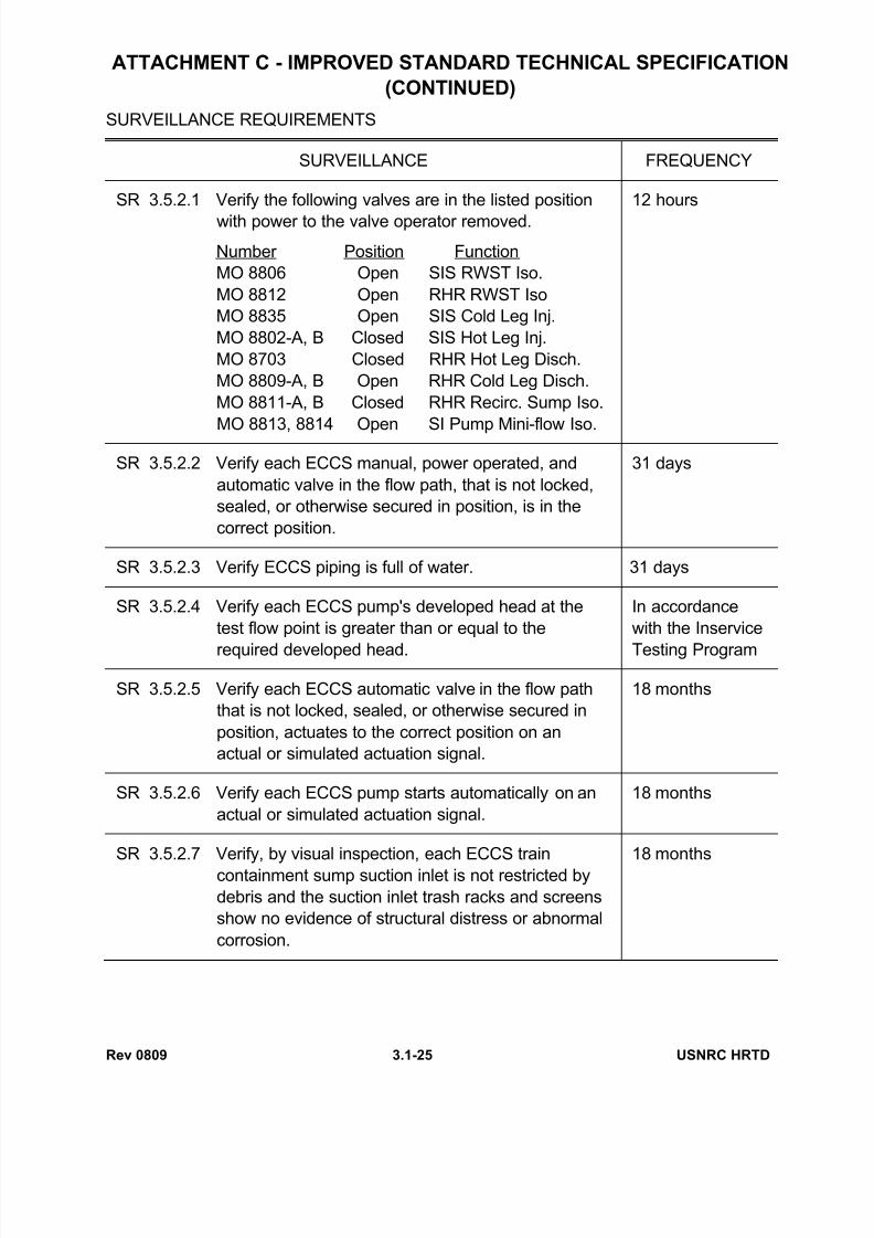
SURVEILLANCE REQUIREMENTS
SURVEILLANCE FREQUENCY
SR 3.5.2.1 Verify the following valves are in the listed position
with power to the valve operator removed.
Number Position Function
MO 8806 Open SIS RWST Iso.
MO 8812 Open RHR RWST Iso
MO 8835 Open SIS Cold Leg Inj.
MO 8802-A, B Closed SIS Hot Leg Inj.
MO 8703 Closed RHR Hot Leg Disch.
MO 8809-A, B Open RHR Cold Leg Disch.
MO 8811-A, B Closed RHR Recirc. Sump Iso.
MO 8813, 8814 Open SI Pump Mini-flow Iso.
12 hours
SR 3.5.2.2 Verify each ECCS manual, power operated, and
automatic valve in the flow path, that is not locked,
sealed, or otherwise secured in position, is in the
correct position.
31 days
SR 3.5.2.3 Verify ECCS piping is full of water. 31 days
SR 3.5.2.4 Verify each ECCS pump's developed head at the
test flow point is greater than or equal to the
required developed head.
In accordance
with the Inservice
Testing Program
SR 3.5.2.5 Verify each ECCS automatic valve in the flow path
that is not locked, sealed, or otherwise secured in
position, actuates to the correct position on an
actual or simulated actuation signal.
18 months
SR 3.5.2.6 Verify each ECCS pump starts automatically on an
actual or simulated actuation signal.
18 months
SR 3.5.2.7 Verify, by visual inspection, each ECCS train
containment sump suction inlet is not restricted by
debris and the suction inlet trash racks and screens
show no evidence of structural distress or abnormal
corrosion.
18 months

7/28/2019 ESPECIFICACIONES TÉCNICAS LÍMITES OPERACIÓN
http://slidepdf.com/reader/full/especificaciones-tecnicas-limites-operacion 28/30
Rev 0809 3.1-26 USNRC HRTD

7/28/2019 ESPECIFICACIONES TÉCNICAS LÍMITES OPERACIÓN
http://slidepdf.com/reader/full/especificaciones-tecnicas-limites-operacion 29/30
Rev 0809 3.1-27 USNRC HRTD
Figure 3.1-1 Reactor Core Safety Limits vs. Boundary of Protection

7/28/2019 ESPECIFICACIONES TÉCNICAS LÍMITES OPERACIÓN
http://slidepdf.com/reader/full/especificaciones-tecnicas-limites-operacion 30/30
This page intentionally blank


