article numerical optimalization of the electric bus
TRANSCRIPT
Article 1
Numerical Optimalization of the Electric Bus Radiator in 2
Terms of Noise Emissions and Energy Consumption 3
Artur Głogoza 1, Anna Janicka 2,*, Radosław Włostowski 2 and Maciej Zawiślak 2, 4
1 OE Industry Sp. z o.o., ul. Marcika 6, 30-443 Kraków, Polska, e-mail: [email protected] 5 2 Wrocław University of Science and Technology, Division of Automotive Engineering, ul. Wyb. 6
Wyspiańskiego 27, Wrocław, Polska, e-mail: [email protected] 7 * Correspondence: [email protected]; Tel.: +48 71 347 79 18 8
Abstract: The dynamic development of electromobility poses challenges to designers regarding not 9
only the efficiency of energy transformation but also the battery life, which is influenced by the 10
stability of its operating temperature. Designing cooling systems is connected not only with the 11
optimization of energy management but also with other environmental parameters, such as noise 12
emission. The paper presents the numerical optimization of an innovative radiator for use in electric 13
buses in terms of energy consumption and noise emission. The results of the numerical studies were 14
verified in laboratory and field conditions, showing a very good convergence of the model with the 15
results of the experiments. 16
Keywords: automotive engineering, electric bus, CFD, numerical fluid mechanics, electromobility, 17
noise, eco-design 18
19
1. Introduction 20
The multi-faceted eco-design of motor vehicles concerns not only reduction and op- 21
timization of energy and material consumption as well as pollutant emissions, but also 22
aspects related to vibration and noise protection for both vehicle users and the external 23
environment. The structure of the motor vehicle market is changing dynamically. In ad- 24
dition to the challenges common to all types of vehicles, such as aerodynamics and body 25
morphology, eco-design varies greatly depending on the type of drive used. 26
In the case of conventional vehicles, equipped with internal combustion engines 27
(ICE), designing in accordance with the principles of sustainable development currently 28
focuses mainly on rightsizing trends, improving the efficiency of fuel combustion and its 29
composition as well as the efficiency of exhaust gas treatment systems. An interesting ap- 30
proach to improving the efficiency of ICE is demonstrated in the work of Sroka and Sadlak 31
[1], where the authors present study results showing that the use of an active combustion 32
chamber (based on thermal barriers) can improve the effective efficiency of the engine 33
from 10 to 20%. 34
However, the dynamic development of electromobility observed in the last decade 35
poses further challenges for designers. In addition to the issue of energy transformation 36
efficiency, lifetime, capacity and recycling of batteries, there are also areas of concern iden- 37
tical to the vehicles equipped with a classic drive, such as noise emission. In this case, 38
nevertheless, it does not apply to the drive unit itself, i.e. the electric motor, but to the 39
coexisting systems. The use of an electric motor both as a stand-alone drive and in a hybrid 40
system requires the use of new solutions in the field of cooling systems whose task is to 41
maintain the vehicle's batteries in appropriate thermal conditions. 42
The thermoregulation systems of batteries for use in electric vehicles are currently 43
the subject of numerous studies related to energy optimization, the type and composition 44
of the coolant, their effectiveness, noise emission and control. Shashank [2] (2018), in his 45
literature review, emphasized the importance of thermal management in electric vehicles 46
and its impact on the life of lithium-ion batteries, which are significantly sensitive to 47
Preprints (www.preprints.org) | NOT PEER-REVIEWED | Posted: 26 January 2021 doi:10.20944/preprints202101.0542.v1
© 2021 by the author(s). Distributed under a Creative Commons CC BY license.

temperature. A year later, a similar review paper was published by Kim [3] (2019), demon- 48
strating the advantages and disadvantages of various battery thermal management sys- 49
tem (BTMS) solutions and presenting his own solution in this area. The dynamic develop- 50
ment of technology and the ever-growing interest in battery cooling are also indicated in 51
a paper published the following year. Mengyao et al. [4] (2020) demonstrated advances in 52
research on electric vehicle cooling technology aimed at eliminating temperature peaks 53
and large temperature gradients. He presented an overview of existing battery thermal 54
management systems, the advantages and disadvantages of cooling systems based on 55
both air and liquid cooling. He defined the trends in their development, such as miniatur- 56
ization or reduction of relatively high energy demand. The paper also indicated that min- 57
imizing the impact on user comfort (mainly in relation to the noise generated by the air- 58
flow through the fan and enclosure) is an important research issue. 59
The problem of research on BTMS was also highlighted by Akinlabi and Solyali [5] 60
(2020), who identified the incorrect temperature distribution in the battery pack (primarily 61
in the significant temperature difference) as the cause of the main problems related to the 62
battery operation. Jing et al [6] (2020) stressed the importance of environmental aspects in 63
the design of vehicle cooling systems and presented the results of a research study aimed 64
at a detailed analysis of the operating medium in terms of environmental aspects. Shen 65
and Gao [7] (2020) focused on the properties of the cooling medium in liquid-cooled bat- 66
tery systems and their impact on cooling efficiency. Another team of researchers has pub- 67
lished interesting papers on the possibility of using heat pumps to cool car batteries. Dong 68
et al [8] (2020) and Wang et al [9] (2020) have shown in their experimental studies that 69
such solutions have a high application potential in motor vehicles. Chen et al [10] (2021) 70
confirmed their conclusions by proposing a carbon dioxide-based heat pump for cooling 71
electric vehicle batteries. However, the researchers Qiu and Shi [11] (2020), presenting 72
their theoretical analysis results, lean in their considerations towards thermoelectric cool- 73
ing. 74
Numerical fluid mechanics, which is a research tool enabling the modeling of the 75
effects of flow phenomena both for the purposes of analysis and diagnostics of systems, 76
as well as their multi-criteria optimization, has been used since the 1990s as a research 77
method for vehicle design, and in recent years in electric vehicles, in particular in solving 78
problems of aerodynamics, energy management and noise modeling. In Zawiślak's paper 79
[12] (2017), a review of the research conducted so far was made and then a method for 80
designing flow machines and systems using CFD methods on the micro and macro flow 81
scale was proposed and described. Three years later, Ruiqing et al [13] (2020), reviewing 82
the applications of CFD methods in the last decade (2010-2020), conclude that it is not only 83
a tool for the diagnosis and design of flow devices and systems, but also a tool for a better 84
understanding of the physical phenomena occurring in the flow system, indicating nu- 85
merous possibilities for the use in the latest solutions in non-conventional vehicles (in- 86
cluding electric vehicles). 87
Haowen et al.’s [14] (2017) paper presents the problem of noise distribution in the 88
electric vehicle cabin, taking into account multiple sources. The authors indicate that the 89
use of three-dimensional CFD calculations on the basis of a two-equation k-ɛ turbulence 90
model allows for very good consistency of the calculation results with the measurement 91
results. Zhang et al [15] (2017) applied numerical fluid mechanics to optimize the vehicle 92
cooling system by taking into account the geometry of the entire vehicle under operational 93
conditions. The researchers' interest was focused on optimizing the radiator and the cool- 94
ing drag. Thanks to the use of CFD methods, design recommendations for efficient vehicle 95
cooling have been specified. 96
Recently, there has been a significant increase of the numericians’ interest in the cool- 97
ing of electric vehicle batteries. Hamidreza et al [16] (2020), using CFD methods, per- 98
formed a comparative analysis of different hybrid vehicle battery cooling techniques and 99
methods to assess the efficiency of thermal management. Also Benabdelaziz et al [17] 100
(2020) successfully use CFD tools to test battery cooling efficiency with the developed so- 101
lution in various geometric variants. The result of the execution of their work is an 102
Preprints (www.preprints.org) | NOT PEER-REVIEWED | Posted: 26 January 2021 doi:10.20944/preprints202101.0542.v1

improvement in the operation of the cooling system based on proprietary solutions (in- 103
cluding heat-pipe [16]), understood as a reduction of the temperature gradient on the bat- 104
tery pack. Yuan et al [18] (2020) identifies numerical and co-numerical modeling of flows 105
based on the latest available computational fluid mechanics tools as the right direction for 106
the design of cooling systems for vehicle components. 107
2. 2. The research object and purpose 108
The object of the research were radiators with an air distribution system in the hous- 109
ing, intended for use in cooling a pack of lithium-ion batteries / fuel cells. The developed 110
solution can be applied in buses with an electric drive, including those with an optional 111
braking resistor and in vehicles with a hydrogen drive. The cooling systems have been 112
designed using the best available technologies in terms of material selection, type and 113
shape of the core cross-section and verified using CFD methods. 114
The modules were equipped with a set of fans, liquid and air temperature sensors, a 115
wire harness adapted to communication via the CAN 2.0B bus, with a transmission speed 116
of 250Kbps. Dedicated control systems with proprietary software enabling autonomous 117
operation with the lowest possible demand for electricity have been developed and man- 118
ufactured. The view of the research object - the object of numerical analysis - is shown in 119
Figure 1. 120
121
Figure 1. The research object 122
The aim of the research was numerical optimization of the device for minimizing 123
noise emissions (improving the comfort of bus users) while maintaining the desired high 124
efficiency of cooling the battery pack 125
3.The research methods 126
Numerical (simulation) tests were performed using the finite volume method (MOS), 127
with the application of numerical fluid mechanics methods. ANSYS-FLUENT software 128
was used. The flow of the cooling medium (air) was modeled using the RANS method. 129
The two-equation k-ɛ turbulence model, the heat transfer model and the acoustic model 130
were used. In order to determine the flow velocity boundary conditions, the available 131
characteristics of the fan intended for use in the designed radiator were used. The as- 132
sumed air temperature was 298 K and the assumed fluid temperature in the radiator was 133
373 K. 134
Preprints (www.preprints.org) | NOT PEER-REVIEWED | Posted: 26 January 2021 doi:10.20944/preprints202101.0542.v1
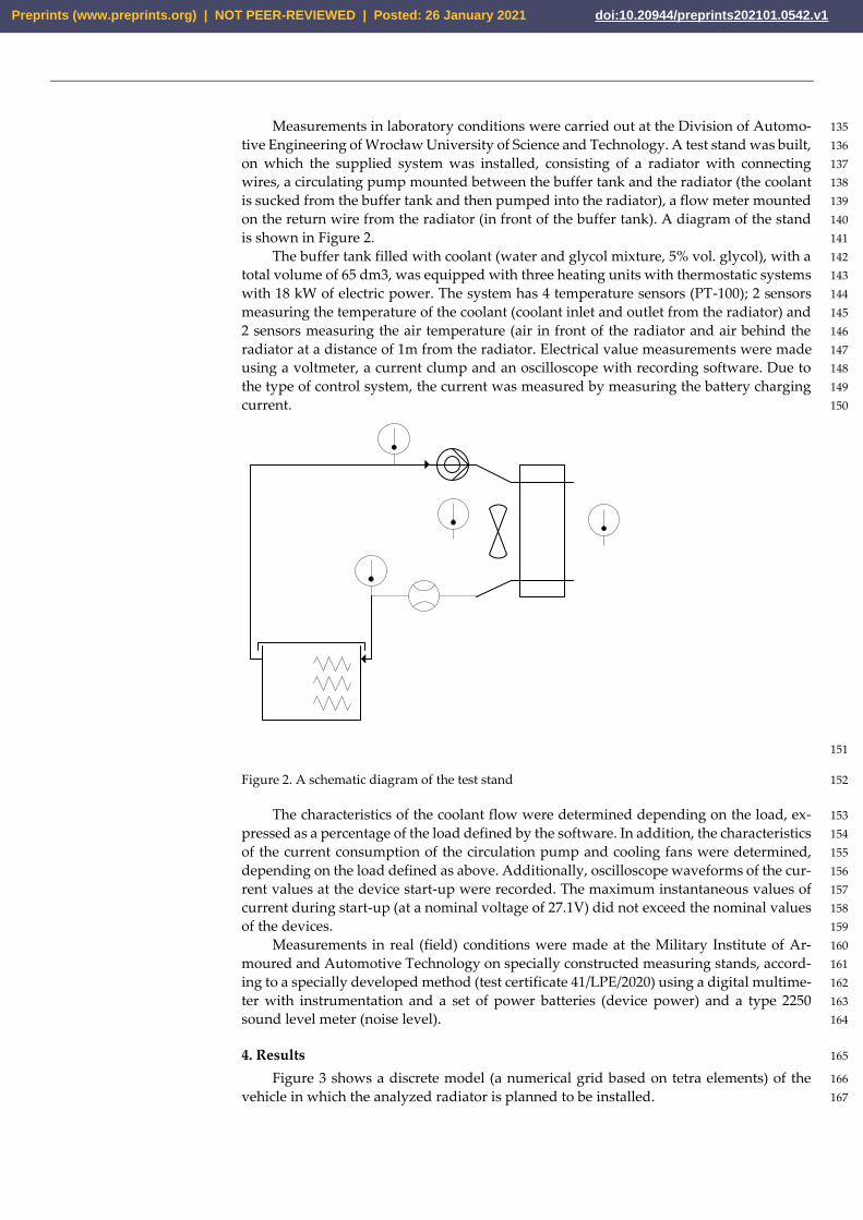
Measurements in laboratory conditions were carried out at the Division of Automo- 135
tive Engineering of Wrocław University of Science and Technology. A test stand was built, 136
on which the supplied system was installed, consisting of a radiator with connecting 137
wires, a circulating pump mounted between the buffer tank and the radiator (the coolant 138
is sucked from the buffer tank and then pumped into the radiator), a flow meter mounted 139
on the return wire from the radiator (in front of the buffer tank). A diagram of the stand 140
is shown in Figure 2. 141
The buffer tank filled with coolant (water and glycol mixture, 5% vol. glycol), with a 142
total volume of 65 dm3, was equipped with three heating units with thermostatic systems 143
with 18 kW of electric power. The system has 4 temperature sensors (PT-100); 2 sensors 144
measuring the temperature of the coolant (coolant inlet and outlet from the radiator) and 145
2 sensors measuring the air temperature (air in front of the radiator and air behind the 146
radiator at a distance of 1m from the radiator. Electrical value measurements were made 147
using a voltmeter, a current clump and an oscilloscope with recording software. Due to 148
the type of control system, the current was measured by measuring the battery charging 149
current. 150
151
Figure 2. A schematic diagram of the test stand 152
The characteristics of the coolant flow were determined depending on the load, ex- 153
pressed as a percentage of the load defined by the software. In addition, the characteristics 154
of the current consumption of the circulation pump and cooling fans were determined, 155
depending on the load defined as above. Additionally, oscilloscope waveforms of the cur- 156
rent values at the device start-up were recorded. The maximum instantaneous values of 157
current during start-up (at a nominal voltage of 27.1V) did not exceed the nominal values 158
of the devices. 159
Measurements in real (field) conditions were made at the Military Institute of Ar- 160
moured and Automotive Technology on specially constructed measuring stands, accord- 161
ing to a specially developed method (test certificate 41/LPE/2020) using a digital multime- 162
ter with instrumentation and a set of power batteries (device power) and a type 2250 163
sound level meter (noise level). 164
4. Results 165
Figure 3 shows a discrete model (a numerical grid based on tetra elements) of the 166
vehicle in which the analyzed radiator is planned to be installed. 167
Preprints (www.preprints.org) | NOT PEER-REVIEWED | Posted: 26 January 2021 doi:10.20944/preprints202101.0542.v1

168
Figure 3. A discrete model of an electric vehicle (bus) 169
A simulation of airflow around the vehicle was performed in order to determine 170
whether there are no adverse flow phenomena at the cooling system attachment point 171
(shown in Figure 3). 172
Figure 4 presents the results of calculations showing the behavior of the streamlines 173
during the flow under the given speed conditions (90 km/h). 174
175
Figure 4. Streamlines - view of the bus from the front of the vehicle on the side of radiator mount- 176 ing 177
Streamlines - radiator inlet grilles and streamlines with operating fans are shown in 178
Figure 5. 179
(a) (b)
Preprints (www.preprints.org) | NOT PEER-REVIEWED | Posted: 26 January 2021 doi:10.20944/preprints202101.0542.v1

Figure 5. Streamlines - radiator inlet grilles and streamlines with operating fans: view of the inlet grilles: a) when the vehicle is 180
moving without the cooling system on, b) when the vehicle is moving with the cooling system on. 181
Despite the correct flow of air around the vehicle (Figure 4), it was found that when 182
the radiator fans were switched on, the flow into and out of the radiator box has swirl 183
zones and dead zones of the flow. In order to improve the flow condition (air inlet and 184
outlet from the system), an analysis of the flow inside the radiator attachment point with 185
operating fans (inside the radiator housing) was performed. The calculation results are 186
presented in Figure 6. 187
188
Figure 6. Streamlines inside the radiator box 189
Observation of the streamlines indicates the need for precise direction the stream 190
flow through the use of guide vanes. 191
The simulation results showed dead fields of the flow, i.e. a decrease in the efficiency 192
of the radiators and noise levels above 72 dB. In addition, the position of the fans was 193
found to be correct (no stream detachment and no flow swirl). However, flow-dead zones 194
were observed during the operation of the fans. It was decided to redesign the fan-housing 195
box. Four geometric models were selected for analysis (Figure 7). They were modeled at 196
the operating point corresponding to 50% of the fan load in the following geometry vari- 197
ants: 198
(a) without a guide vane, 199 (b) with one guide vane, 200 (c) with two guide vanes, 201 (d) with stream separation. 202
Figure 8 shows the simulation results in the form of a determined distribution of acoustic 203
pressure fields 204
(a) (b)
Preprints (www.preprints.org) | NOT PEER-REVIEWED | Posted: 26 January 2021 doi:10.20944/preprints202101.0542.v1

(c) (d)
Figure 7. Geometric models: (a) without guide vanes, (b) with one stream guide vane, (c) with two stream guide vanes, (d) with 205
stream separation. 206
(a) (b)
(c) (d)
Figure 8. Acoustic pressure fields [dB]: (a) without guide vanes, (b) with one stream guide vane, (c) with two stream guide vanes, 207
(d) with stream separation. 208
(a) (b)
Preprints (www.preprints.org) | NOT PEER-REVIEWED | Posted: 26 January 2021 doi:10.20944/preprints202101.0542.v1

(c) (d)
Figure 9. Velocity vector fields [m/s] (a) without guide vanes, (b) with one stream guide vane, (c) with two stream guide vanes, (d) 209
with stream separation 210
(a) (b)
(c) (d)
Figure 10. Inlet and outlet velocity vector fields [m/s] (a) without guide vanes, (b) with one stream guide vane, (c) with two stream 211
guide vanes, (d) with stream separation. 212
Velocity vector fields are shown in Figure 9, while inlet and outlet velocity vector fields 213
are presented in Figure 10. 214
As a result of the simulation, it was found that the best solution in terms of noise 215
emission as well as the occurring flow phenomena was obtained for variant d) – the vari- 216
ant with the stream separation. The maximum values of the noise level for this variant 217
were estimated at 57 dB. 218
Obtaining an even flow through the radiators also allows for the best cooling performance 219
(energy efficiency). The geometry of the system is shown in Figure 11. 220
Preprints (www.preprints.org) | NOT PEER-REVIEWED | Posted: 26 January 2021 doi:10.20944/preprints202101.0542.v1

221
Figure 11. Selected radiator geometry 222
In the next stage, empirical verification of the numerical model was conducted. A 223
prototype device was made according to the geometric model selected as a result of sim- 224
ulation tests. The experimental tests were conducted in the field conditions at the Military 225
Institute of Armoured and Automotive Technology. Figure 12 shows the view of the test 226
stand during the study implementation. 227
228
Figure 12. The view of the test stand during the performance of acoustic pressure tests of the radi- 229 ator. 230
231
Comparative tests of the base solution (Figure 1) and the solution resulting from the 232
numerical tests were performed (Figure 11). 233
Preprints (www.preprints.org) | NOT PEER-REVIEWED | Posted: 26 January 2021 doi:10.20944/preprints202101.0542.v1

234
Figure 12. Results of noise level measurements – comparison of the base and prototype versions 235 (developed on the basis of numerical analysis) 236
The accuracy of the calculation model was found to be very good – under simulation 237
conditions, the maximum noise level was estimated at 57 dB, under measurement condi- 238
tions for the same operating point (50% of fan power) at 59 dB. 239
Measurements were then carried out to determine the prototype’s power require- 240
ment in laboratory and field conditions according to the measurement methods described 241
in Chapter 3. 242
Figure 13 shows the results of laboratory tests, while Figure 14 shows the results of 243
field tests. 244
245
Figure 14. Cooling fan power consumption depending on the % of the load defined by the control 246 system in laboratory conditions 247
The results of the power measurement in field conditions on the constructed stand 248
are shown in Figure 14. 249
0
200
400
600
800
1000
1200
1400
0 20 40 60 80 100
po
wer
req
uir
emen
t, W
Fans load according to steering system, %
Preprints (www.preprints.org) | NOT PEER-REVIEWED | Posted: 26 January 2021 doi:10.20944/preprints202101.0542.v1

250
Figure 14. Measurement of power requirement in field conditions 251
It was found that the determined characteristics were convergent and that there were 252
no changes in the electric power requirement of the device after the performed optimiza- 253
tion. 254
5. Conclusions 255
256
1. Application of the CFD RANS method of the two-equation k-ɛ turbulence model 257
with the heat transfer and acoustic model as a tool to optimize the vehicle's cooling system 258
in terms of noise emission is a tool adequate for the intended purpose. Consistency of the 259
simulation results and test results of the real object was demonstrated, i.e. 57 dB as a result 260
of the simulation and 59 dB on the basis of field tests. 261
2. The division of the stream of flowing air by the cooling unit caused a decrease in 262
the maximum velocity values, resulting in a decrease in the resistance of the flowing 263
stream. 264
3. Reducing the pressure level and obtaining an even flow through the radiators al- 265
lowed for a higher cooling efficiency while maintaining a comparable level of electric 266
power. 267
268 Acknowledgements: The research was conducted as part of a project co-financed by the National 269 Centre for Research and Development entitled: “Innowacyjna generacja ultralekkich modułów 270 chłodzących o zminimalizowanym poziomie emisji hałasu, zapotrzebowania na energię el- 271 ektryczną, poprzez zaimplementowany nowy system bieżącego monitorowania parametrów pracy, 272 przeznaczony do nowych pojazdów z napędem elektrycznym w tym zasilanych ogniwami wodor- 273 owymi” [Innovative generation of ultra-light cooling modules with minimized noise emission, elec- 274 tricity demand, through the implemented new system of ongoing monitoring of operating parame- 275 ters, intended for new electric vehicles, including those powered by hydrogen cells], project no: 276 POIR.01.01.01-00-0147/17 277
References 278
1. Sroka Z. J., Sadlak Z., Thermal activation of the combustion chamber of a reciprocating internal combustion engine. Journal 279 of Thermal Science. 2018, vol. 27, nr 5, s. 449-455, https://doi.org/10.1007/s11630-018-1039-7 280
2. Shashank Arora; Selection of thermal management system for modular battery packs of electric vehicles: A review of exist- 281 ing and emerging technologies, Journal of Power Sources 400 (2018) 621–640, https://doi.org/10.1016/j.jpowsour.2018.08.020 282
3. Jaewan Kim, Jinwoo Oh, Hoseong Lee, Review on battery thermal management system for electric vehicles, Applied Ther- 283 mal Engineering 149 (2019) 192–212, https://doi.org/10.1016/j.applthermaleng.2018.12.020 284
0
200
400
600
800
1000
1200
1400
1600
0 20 40 60 80 100
Po
wer
req
uir
emen
t, W
Fans power, %
Preprints (www.preprints.org) | NOT PEER-REVIEWED | Posted: 26 January 2021 doi:10.20944/preprints202101.0542.v1

4. Mengyao Lu, Xuelai Zhang, Jun Ji, Xiaofeng Xu, Yongyichuan Zhang; Research progress on power battery cooling technol- 285 ogy for electric vehicles, Journal of Energy Storage 27 (2020) 101155, https://doi.org/10.1016/j.est.2019.101155 286
5. A.A. Hakeem Akinlabi, Davut Solyali: Configuration, design, and optimization of air-cooled battery thermal management 287 system for electric vehicles: A review, Renewable and Sustainable Energy Reviews 125 (2020) 109815, 288 https://doi.org/10.1016/j.rser.2020.109815 289
6. Jing Wu, Guoliang Zhou, Mingyu Wang A comprehensive assessment of refrigerants for cabin heating and cooling on elec- 290 tric vehicles, Applied Thermal Engineering 174 (2020) 115258, https://doi.org/10.1016/j.applthermaleng.2020.115258 291
7. Ming Shen, Qing Gao, Structure design and effect analysis on refrigerant cooling enhancement of battery thermal manage- 292 ment system for electric vehicles, Journal of Energy Storage 32 (2020) 101940, https://doi.org/10.1016/j.est.2020.101940 293
8. DONG Junqi, WANG Yibiao, JIA Shiwei, ZHANG Xianhui, HUANG Linjie: Experimental Study of R744 Heat Pump System 294 for Electric Vehicle Application, Applied Thermal Engineering (2020), https://doi.org/10.1016/j.applthermaleng.2020.116191 295
9. Yibiao WANG , Junqi DONG , Shiwei JIA , Linjie HUANG , Experimental Comparison of R744 and R134a Heat Pump 296 Systems for Electric Vehicle Application, International, Journal of Refrigeration (2020), doi: https://doi.org/10.1016/j.ijre- 297 frig.2020.10.026 298
10. Yiyu Chen, Huiming Zou, Junqi Dong, Jiang Wu, Hongbo Xu , Changqing Tian, Experimental investigation on the heating 299 performance of a CO2 heat pump system with intermediate cooling for electric vehicles, Applied Thermal Engineering 182 300 (2021) 116039 301
11. Changsheng Qiu, Wankai Shi, Comprehensive modeling for optimized design of a thermoelectric cooler with non-constant 302 cross-section: Theoretical considerations, Applied Thermal Engineering 176 (2020) 115384, https://doi.org/10.1016/j.ap- 303 plthermaleng.2020.115384 304
12. Zawiślak M. Method of designing and modernising machines and flow systems using Computational Fluid Mechanics, 305 2017, Wydawnictwo Politechniki Poznańskiej 306
13. Ruiqing Shen, Zeren Jiao, Trent Parker, Yue Sun, Qingsheng Wang: Recent application of Computational Fluid Dynamics 307 (CFD) in process safety and loss prevention: A review, Journal of Loss Prevention in the Process Industries 67 (2020) 104252, 308 https://doi.org/10.1016/j.jlp.2020.104252 309
14. Haowen Yuan, Hongchun Su, Li Wangc, Chun Yuan, Zhebin Zhang: Numerical analysis on airflow and thermal field in 310 quiet power vehicle compartment, Procedia Engineering 174 (2017 ) 571 – 578 doi: 10.1016/j.proeng.2017.01.189 311
15. Chunhui Zhang, Mesbah Uddin, Austin Clay Robinson, Lee Foster, Full vehicle CFD investigations on the influence of front- 312 end configuration on radiator performance and cooling drag, Applied Thermal Engineering 130 (2018) 1328–1340, 313 https://doi.org/10.1016/j.applthermaleng.2017.11.086 314
16. Hamidreza Behia, Danial Karimia, Mohammadreza Behic, Morteza Ghanbarpourd, Joris Jaguemonta, Mohsen Akbarzadeh 315 Sokkeha, Foad Heidari Gandomana, Maitane Berecibara, Joeri Van Mierlo, A new concept of thermal management system 316 in Li-ion battery using air cooling and heat pipe for electric vehicles, Applied Thermal Engineering 174 (2020) 115280, 317 https://doi.org/10.1016/j.applthermaleng.2020.115280 318
17. Kawtar Benabdelaziz, Badreddine Lebrouhi, Anas Maftah, Mohammed Maaroufi: Novel external cooling solution for elec- 319 tric vehicle battery pack Energy Reports 6 (2020) 262–272, https://doi.org/10.1016/j.egyr.2019.10.043 320
18. Ruoyang Yuan, Tom Fletcher, Ahmed Ahmedov, Nikolaos Kalantzis, Antonios Pezouvanis, Nilabza Dutta, Andrew Wat- 321 son, Kambiz Ebrahimi: Modelling and Co-simulation of hybrid vehicles: A thermal management perspective: Applied Ther- 322 mal Engineering 180 (2020) 115883, https://doi.org/10.1016/j.applthermaleng.2020.115883 323
Preprints (www.preprints.org) | NOT PEER-REVIEWED | Posted: 26 January 2021 doi:10.20944/preprints202101.0542.v1