wall mount slim / vesa size 400 - vogels-halterung.de
TRANSCRIPT

240–
3520
9 04
0
Wall Mount Slim / VESA Size 400Zubehör TV Toebehoren TVTV accessoriesAccessoires TVAccessori TVAccesorios TV
Montageanleitung, Montagehandleiding, Installation instructions, Instructions de montage, Istruzioni di montaggio, Instrucciones de montaje,
Advertencias de seguridad e
Tenga en cuenta las indicaciones del manual. Utilice las herramientas con precaución.
Instale la combinación de aparatos de manera que no presente riesgo de lesiones, p. ej., para niños que estén jugando cerca, y de manera que no pueda sufrir daños.
Los adaptadores VESA Size únicamente pueden utilizarse para construcciones portantes autoriza-das o paredes verticales En este caso también son aplicables las adverten-cias de seguridad de nuestros televisores.
Veiligheidsvoorschriften l
Houd rekening met de informatie in de
gebruiksaanwijzing. Wees voorzichtig bij de omgang met werktuigen.
Plaats de toestelcombinatie zo, dat ze geen gevaar vormt voor bijvoorbeeld spelende kinderen en dat ze ook niet kan worden beschadigd.
VESA Size-adapters mogen enkel worden gebruikt voor toegelaten draagconstructies of loodrechte wandenVerder zijn de veiligheidsvoorschriften voor onze tv-toestellen ook hier van toepassing.
Instructions de sécurité f
Veuillez observer les informations du mode d’emploi. Soyez prudent lors de l’utilisation d’outils.
Positionnez votre combinaison d’appareils de telle sorte qu’elle ne représente p. ex. aucun danger pour des enfants en train de jouer et qu’elle ne puisse pas être renversée.
Les adaptateurs au format VESA sont à utiliser uniquement pour les structures portantes autori-sées et les parois verticales Par ailleurs, les instructions de sécurité relatives à nos téléviseurs sont également valables ici.
Safety instructions g
Observe the information in the instructions. Han-dle tools with the necessary care and attention.
Install your combination of equipment in such a way that it presents no danger to playing children for example and also cannot be damaged.
VESA Size adaptors may only be used for permis-sible support structures or vertical walls The safety notes for our TV sets are also ap-plicable here.
Sicherheitshinweise d
Beachten Sie die Informationen der Anleitung.Lassen Sie im Umgang mit Werkzeug die nötige Vorsicht walten.
Stellen Sie Ihre Gerätekombination so auf, dass sie, z.B. für spielende Kinder keine Gefährdung darstellt und auch nicht beschädigt werden kann.
VESA Size-Adapter sind nur für zugelassene Tragekonstruktionen oder senkrechte Wände zu verwenden Des weiteren haben die Sicherheitshinweise für unsere TV-Geräte auch hier Gültigkeit.
Der neueste Stand der Montageanleitung kann unter ? ? ? vom Netz heruntergeladen werden
1 1a1a
Montage VESA Size 400 d
Montage VESA format 400 f
Montage VESA Size 400 l
Montaggio del VESA Size 400 i
VESA Size 400 assembly g
Montaje del VESA Size 400 e
dMit dem VESA Size 400 können Sie die entsprechenden TV Geräte (Tabelle 1a) befestigen
Eine Befestigung ist am Wall Stand Flex, Wall Mount Iso ex und Screen Lift Plus möglich, Skizze 2 / 2a / 2b
Die Schrauben E zur Befestigung am jeweiligen Produkt erhalten Sie mit dem Produkt, zB. Wall Stand Flex, Skizze
Der Schraubenschlüssel zum fest ziehen der Schrauben ist nicht im Lieferumfang enthalten.
Befestigen Sie den VESA Size 400 K an dem bereits mon-tierten Produkt. (Schrauben E fest anziehen)
lMet de VESA Size 400 kunt u de overeenkomstige tv-toestellen (tabel 1a) bevestigenBevestiging is mogelijk aan de Wall Stand Flex, Wall Mount Iso ex en Screen Lift Plus, tekening 2 / 2a / 2bDe schroeven E ter bevestiging aan het desbetreffend product verkrijgt u met het product, bv. Wall Stand Flex, tekening De schroevendraaier voor het vastdraaien van de schro-even is niet bijgeleverd.Bevestig de VESA Size 400 K aan het reeds gemonteerde product. (schroeven E stevig aandraaien)
gYou can use the VESA Size 400 to fasten the correspond-ing TV sets (table 1a)
Fastening is possible on the Wall Stand Flex, Wall Mount Iso ex and Screen Lift Plus, diagram 2 / 2a / 2b
Screws E for fastening to the relevant product are avail-able with the product, e.g. Wall Stand Flex, Diagram
The spanner for tightening the screws is not included in the scope of supply.Fasten the VESA Size 400 K on the pre-assembled prod-uct. (Tighten screws E tightly)
fAvec le VESA format 400, vous pouvez xer les téléviseurs correspondants (tableau 1a)
La xation peut s'effectuer sur les supports Wall Stand Flex, Wall Mount Iso ex et Screen Lift Plus, schémas 2 / 2a / 2b
Les vis E permettant la xation au produit respectif sont fournies avec le produit, par exemple Wall Stand Flex, schéma La clé nécessaire pour le serrage des vis n'est pas fournie dans la livraison.Fixer le VESA format 400 K sur le produit déjà monté. (serrer les vis E à fond)
iIl VESA Size 400 consente di ssare i rispettivi apparecchi TV (tabella 1a)
E' possibile eseguire il ssaggio sui supporti Wall Stand Flex, Wall Mount Iso ex e Screen Lift Plus, disegno 2 / 2a / 2b
Le viti E per il ssaggio di ogni speci co prodotto vengono fornite con il prodotto stesso, ad es. Wall Stand Flex, disegno
Il cacciavite non è compreso nella dotazione.
Fissare il VESA Size 400 K sul prodotto già montato. (ser-rare a fondo le viti E)
eCon el VESA Size 400, se pueden jar los televisores cor-respondientes (tabla 1a)
Es posible la jación en la Wall Stand Flex, Wall Mount Iso ex y Screen Lift Plus, croquis 2 / 2a / 2bLos tornillos E para la jación en el producto respectivo vienen con el producto, p. ej., Wall Stand Flex, croquis La llave para apretar los tornillos no está incluida en el volumen de suministro.
Fije el VESA Size 400 K en el producto ya montado. (apretar los tornillos E)
E
K
K
E
2
2a2a
TV-Gerät vorbereiten d
Préparation du téléviseur f
Tv-toestel voorbereiden l
Predisposizione dell’apparecchio TV i
Preparing the TV set g
Preparación del televisor e
k1...
k2...
k3...
d
33
Ein Fuß am TV-Gerät muss demontiert werden. TV-Gerät zur Demontage auf weiche Unterlage legen1. Vom Netz trennen, Kabelabdeckung abnehmen2. Befestigungsschrauben (f) am Fuß lösen, Fuß ab- nehmen3. Kabelabdeckung wieder einsetzen (kann auch erst nach Kabelanschluß erfolgen)
l
3
Een eventuele voet op het tv-toestel moet worden gede-monteerd. Leg het tv-toestel voor de demontage op een zachte ondergrond1. Loskoppelen van het net, kabelafdekking verwijderen2. bevestigingsschroeven (f) aan de voet losmaken, voet verwijderen3. Kabelafdekking weer aanbrengen (kan ook pas na kabelaansluiting gebeuren)
g
3
One foot on the TV set must be disassembled. Place TV set on a soft base for disassembly1. Disconnect from mains, remove cable cover2. Remove the fastening screws (f) at the foot; take off foot3. Replace cable cover (can also be done after connecting the cable)
f
3
Un pied du téléviseur doit être démonté. Pour le démon-tage, poser le téléviseur sur un support souple1. Débrancher le téléviseur, retirer le cache-câble2. Desserrer les vis de xation (f) au niveau du pied, retirer le pied3. Remettre le cache-câble en place (ceci n'est possible qu'après le raccordement du câble)
i
3
Un piede dell'apparecchio TV va smontato. Posare l'apparecchio TV su una base morbida per procedere con lo smontaggio1. Staccare dalla rete, togliere la copertura del vano cavi2. Allentare le viti di ssaggio (f), rimuovere il piede3. Applicare nuovamente la copertura del vano cavi (lo si può fare anche soltanto dopo aver collegato i cavi)
e
3
Se debe desmontar el pie del televisor. Para ello, coloque el televisor sobre una base exible.1. Desconéctelo de la red y retire la cubierta de cables.2. A oje los tornillos de jación (f) del pie y retire el pie.3. Vuelva a colocar la cubierta de cables (esto puede realizarse también tras conectar el cable).
VESA Size 400 an TV-Gerät d
VESA format 400 sur le téléviseur f
VESA Size 400 op tv-toestel l
VESA Size 400 sull’apparecchio TV i
VESA Size 400 on TV set g
VESA Size 400 en el televisor e
d
44
Teile k1..., k2... und k3... gemäß Tabelle 4a auswähle.Scheibe k2... so auf die Schraube k3... schieben, dass die Krallen der Scheibe k2... nicht zum Schraubenkopf zeigenSechskantbolzen gemäß Tabelle 4a auswälen, in TV-Geräterückwand einschrauben und fest ziehen Schraube k3... mit Scheibe k2... in die oberen beiden Sechskantbolzen k1... von Hand einschrauben, anschließend 5 Umdrehungn wieder zurück drehen(Abstand ist zum Einhängen nötig)
l
4
Onderelen k1..., k2... en k3... volgens tabel 4a gekozen drukplaatje k2... zo op schroef k3... schuiven, dat de klauwen van het drukplaatje k2... niet in richting schroefkop wijzenZeskantbout volgens tabel 4a selecteren, in achterwand van tv-toestel inschroeven en vast aantrekken Schroef k3... met schijf k2... in de bovenste twee zeskantbouten oberen k1... van hand inschroeven, ver-volgens 5 omwentelingen terug (afstand is nodig voorhet inhangen)
g
4
Select parts k1..., k2... and k3... according to table 4a. Slide washer k2... onto the screw k3... so that the claws of the washer k2... do not point to the screw headSelect hexagon bolts according to table 4a; screw them into the back wall of the TV set and tighten rmly Screw screw k3... with washer k2... into the upper two hexagon bolts k1... by hand, then unscrew back again 5 revolutions (a gap is necessary for hanging in)
f
4
Choisir les pièces k1..., k2... et k3... suivant le tableau 4a. Pousser la rondelle k2... sur la vis k3... de façon à ce que les griffes de la ronelle k2... ne soient pas dirigées vers la tête de visChoisir les boulons hexagonaux suivant le tableau 4a, les visser sur la face arrière du téléviseur puis les serrer à fond Serrer manuellement la vis k3... avec la rondelle k2... dans les deux boulons hexagonaux supérieurs k1... puiseffectuer 5 rotations en sens inverse (distance nécessaire pour l'accrochage)
i
4
Selezionare le parti k1..., k2... e k3... in base alla tabella 4a. Far scorrere la rondella k2... sulla vite k3... in modo che le nervature della rondella k2... non siano rivolte verso la testa della viteSelezionare i bulloni esagonali in base alla tabella 4a, av-vitare alla parete posteriore dell'apparecchio TV Avvitare a mano la vite k3... con la rondella k2... nei due bulloni esagonali superiori k1..., quindi fare altri 5 giri nella direzione inversa (è necessario prevedere la distanza per agganciare l'apparecchio)
e
4
Escoja las piezas k1..., k2... y k3... conforme a la tabla 4a. Deslice las arandelas k2... por los tornillos k3... de modo que los dientes de la arandela k2... indiquen en la dirección contraria a la cabeza del tornillo.Escoja los cilindros roscados conforme a la tabla 4a, enrósquelos en la pared posterior del televisor y apriételos bien.Enrosque manualmente los tornillos k3... con arandelas k2... en ambos cilindros hexagonales k1... superiores. A continuación, desenrósquelos 5 vueltas (la distancia es necesaria para colgar el aparato).
VESA Size 400 ist für nachfolgend genannteTV-Geräte verwendbar, Tabelle 1a d
VESA Size 400 is bruikbaar voor de hieronder vermelde tv-toestellen, tabel 1a l
VESA Size 400 is suitable for use with the fol-lowing TV sets, table 1a g
VESA format 400 est conçu pour lestéléviseurs ci-après, tableau 1a f
VESA Size 400 può essere utilizzato per gli ap-parecchi TV indicati di seguito, tabella 1a i
VESA Size 400 se puede utilizar con lostelevisores que se detallan a continuación, tabla 1a
e
50430x4x TV Individual 40 Compose 3D69418x80 TV Individual 40 Selection LED 200 69418x47 TV Individual 40 Selection LED 200 DR +69408x4x TV Individual 40 Compose LED 40069419x80 TV Individual 46 Selection LED 20069419x47 TV Individual 46 Selection LED 200 DR +69409x4x TV Individual 46 Compose LED 40050431x4x TV Individual 46 Compose 3D50432x48 TV Individual 55 Compose 3D69410x48 TV Individual 55 Compose LED 400
51462w80 TV Connect ID 32 Set51462x84 TV Connect ID 32 51462x44 TV Connect ID 32 DR +51463w80 TV Connect ID 40 Set 51463x84 TV Connect ID 40 51463x44 TV Connect ID 40 Set51464w80 TV Connect ID 46 Set51464x84 TV Connect ID 4651464x44 TV Connect ID 46 DR +
51439x80 TV Xelos 40 (MB 180)52449x80 TV Xelos 46 (MB 180)
VESA Size 400 d
VESA Size 400 f
VESA Size 400 l
VESA Size 400 i
VESA Size 400 g
VESA Size 400 e
VESA Size 400
Screen Lift Plus
Wall Mount Isoflex
Wall Stand Flex
Screen Lift Plus
k3.8 (M8 x 16)
k1.20
k1.20
k1.20
k1.20
k1.32
k1.32
k1.32
k1.32
k1.45
k1.45
k1.45
k1.45
k3.8 (M8 x 16)
k3.8 (M8 x 16)
k3.8 (M8 x 16)
K
P
P
P
P
k3.6 (M6 x 16)
k2.6 (Z 7,4)
k2.8 (Z 8,2)
k2.8 (Z 8,2)
k2.8 (Z 8,2)
k2.8 (Z 8,2)
Lieferumfang Skizze 1b d
K VESA Size Adapterplatte 71361T00
k1.32 Sechskantbolzen M8 x 32 4 Stückk1.45 Sechskantbolzen M6 x 45 4 Stückk3.8 Befestigungsschrauben M8 x 16 4 Stückk3.6 Befestigungsschrauben M6 x 16 4 Stückk2.8 Kontaktscheibe für M8 Form Z 8,2 4 Stückk2.6 Scheibe für M6 Form Z 7,4 4 StückP Puffer 4 Stück
Leveringsinhoud tekening 1b l
K VESA Size-adapterplaat 71361T00
k1.32 Zeskantbouten M8 x 32 4 stuksk1.45 Zeskantbouten M6 x 45 4 stuksk3.8 Bevestigingsschroeven M8 x 16 4 stuksk3.6 Bevestigingsschroeven M6 x 16 4 stuksk2.8 Contactplaatje voor M8 vorm Z 8,2 4 stuksk2.6 Contactplaatje voor M6 vorm Z 7,4 4 stuksP Buffer 4 stuks
Scope of Supply Diagram 1b g
K VESA Size adaptor plate 71361T00
k1.32 Hexagon bolt M8 x 32 4 itemsk1.45 Hexagon bolt M6 x 45 4 itemsk3.8 Fastening screw M8 x 16 4 itemsk3.6 Fastening screw M6 x 16 4 itemsk2.8 Contact washer for M8 shape Z 8.2 4 itemsk2.6 Contact washer for M6 shape Z 7.4 4 itemsP Buffer 4 items
Contenu de la livraison Schéma 1b f
K Plaque adaptateur format VESA 71361 T00
k1.32 Boulon hexagonal M8 x 32 4 piècesk1.45 Boulon hexagonal M6 x 45 4 piècesk3.8 Vis de xation M8 x 16 4 piècesk3.6 Vis de xation M6 x 16 4 piècesk2.8 Rondelle de contact pour M8 Forme Z 8,2 4 piècesk2.6 Rondelle de contact pour M6 Forme Z 7,4 4 piècesP Tampon 4 pièces
Dotazione disegno 1b i
K VESA Size piastra adattatrice 71361T00
k1.32 Bulloni esagonali M8 x 32 4 pezzik1.45 Bulloni esagonali M6 x 45 4 pezzik3.8 Viti di ssaggio M8 x 16 4 pezzik3.6 Viti di ssaggio M6 x 16 4 pezzik2.8 Rondella per M8 forma Z 8,2 4 pezzik2.6 Rondella per M6 forma Z 7,4 4 pezziP Tamponi 4 pezzi
Volumen de suministro croquis 1b e
K Placa adaptadora VESA Size 71361T00
k1.32 Cilindros hexagonales M8 x 32 4 unidadesk1.45 Cilindros hexagonales M6 x 45 4 unidadesk3.8 Tornillos de jación M8 x 16 4 piezask3.6 Tornillos de jación M6 x 16 4 piezask2.8 Arandelas de contacto para M8 Fo Z 8,2 4 unidadesk2.6 Arandelas de contacto para M6 Fo Z 7,4 4 unidadesP Topes 4 unidades
ff
E
K
Wall Stand Flex
Wall Mount Iso ex Screen Lift Plus2b2b f
f
d
55
Die notwendigen Kabel am TV-Gerät anschließenNehmen Sie hier die Bedienungsanleirung des entsprech-enden TV-Gerätes zu Hilfe.Brechen Sie die vorgesehenen perforierten notwendigen Stellen an der Kabelabdeckung aus. Setzen Sie die Kabelabelabdeckung wieder ein.
l
5
Sluit de vereiste kabels aan op het tv-toestelRaadpleeg nu de handleiding van het betreffende tv-toestel.Breek de voorziene geperforeerde openingen in de kabelafdekking open. Breng de kabelafdekking opnieuw aan.
g
5
Connect the required cables to the TV setConsult the instructions for use of the corresponding TV set for help here.Break out the provided perforated required points on the cable cover. Replace the cable cover again.
f
5
Raccorder les câbles requis au téléviseurÀ cet effet, se reporter à la notice technique du téléviseur concerné.Parmi les emplacements perforés du cache-câble, ouvrir ceux qui sont nécessaires. Remettre le cache-câble en place.
i
5
Collegare i cavi necessari all'apparecchio TVSe necessario, consultare il manuale d'istruzioni del rispettivo apparecchio TV.Aprire la copertura del vano cavi lungo la linea perforata. Applicare nuovamente la copertura del vano cavi.
e
5
Conectar los cables necesarios al televisorSírvase del manual de instrucciones del televisor cor-respondiente.Abra la parte de la cubierta de cables necesaria sirvién-dose de las perforaciones de esta. Vuelva a colocar la cubierta de cables.
1b 3
4
5
Indicazioni di sicurezza i
Fare attenzione alle informazioni del manuale d’uso. Utilizzare gli attrezzi con la dovuta cautela.
Installare la combinazione di apparecchi in modo tale che non possa essere danneggiata e che non rappresenti un pericolo, ad esempio per i bambini che giocano.
Gli adattatori VESA Size si possono utilizzare soltanto sulle strutture portanti consentite oppure su pareti verticali Le indicazioni di sicurezza relative ai nostri appar-ecchi TV valgono anche in questo caso.
Wall Mount Slim / VESA Size 400Art. Nr. 71361T00
Printed in Germany KB 0312
Änderungen vorbehalten.Wijzigingen voorbehouden.Subject to modi cations.Modi cations reservée.Con riserva di modi che.Reservado el drecho a modi caciones.
Deutschland
Loewe Opta GmbHCustomer Care Center
Industriestraße 11D-96305 KronachD-96317 Kronach
Telefon 01801/22256393Telefax (09261) 99500
ff ff
TV k1.32 k1.45 k3.6 k3.8 k2.6 k2.8
Individual 40 ... X X X Individual 46 ... X X X Individual 55 ... X X X
Connect 32 ... X X X Connect 40 ... X X X Connect 46 ... X X X Xelos 40 (MB180) X X X Xelos 46 (MB180) X X X
4a 32
k
45 M6 M8
7,4 8,2
K
k2...
k3...
d
66
Mit Hilfe einer weiteren Person hängen Sie das TV-Gerät mit den Schrauben k3... oben in die Schlitze der Adapt-erplatte K ein.
Die unteren 2 Schrauben k3... mit Scheiben k2... durch die Bohrungen in der Adapterplatte K in die Sechskant-bolzen am TV-Gerät einschrauben.
l
6
Met behulp van een verdere persoon hangt u het tv-toestel met de schroeven k3... boven in de gleuf van de adapterplaat K in.
De onderste 2 schroeven k3... met drukplaatjes k2... door de boringen in de adapterplaat K in de zeskant-bouten op het tv-toestel inschroeven.
g
6
Enlist the help of another person to hang the TV set with the upper screws k3... into the slot of the adaptor plate K.
Screw the 2 lower screws k3... with washers k2... through the holes in the adaptor plate K into the hexagon bolts on the TV set.
f
6
Avec l'aide d'une tierce personne, accrocher le téléviseur avec les vis k3... en haut, dans la fente de la plaque adaptateur K.
Visser les 2 vis inférieures k3... avec les rondelles k2... en les faisant passer dans les perçages de la plaque adapta-teur K dans les boulons hexagonaux du téléviseur.
i
6
Con l’aiuto di una seconda persona, appendere l'apparecchio TV con le viti k3... in alto nella fessura della piastra adattatrice K.
Avvitare le 2 viti inferiori k3... con le rondelle k2... nei fori della piastra adattatrice K nei bulloni esagonali dell'apparecchio TV.
e
6
Con ayuda de otra persona, cuelgue el televisor colo-cando los tornillos k3... arriba en las ranuras de la placa adaptadora K.
Atornille los 2 tornillos inferiores k3... con las arandelas k2..., a través de los ori cios de la placa adaptadora K, en los cilindros hexagonales del televisor.
TV-Gerät mit VESA Size 400 d
Téléviseur avec VESA format 400 f
Tv-toestel met VESA Size 400 l
Apparecchio TV con VESA Size 400 i
TV set with VESA Size 400 g
Televisor con VESA Size 400 e
d
77Mit dem passenden Schraubenschlüssel (nicht im Lief-erumfang enthalten) ziehen Sie alle 4 Schrauben fest.Die benötigten Kabel haben Sie am TV-Gerät angeschlos-sen und die Kabelabdeckung wieder eingesetzt
l
7Draai alle 4 schroeven met een passende schroevendraaier (niet in de levering) vast.De benodigde kabels hebt u op het tv-toestel aangesloten en de kabelafdekking heeft u opnieuw aangebracht
g
7Use a suitable spanner (not included in the scope of sup-ply) to tighten all 4 screws.You have connected the required cables to the TV set and replaced the cable cover again
f
7À l'aide de la clé de serrage adaptée (non fournie dans la livraison), serrer les 4 vis à fond.Vous avez raccordé les câbles requis au téléviseur et remis en place le cache-câble.
i
7Con il cacciavite adatto (non fornito) serrare tutte le 4 viti.I cavi necessari sono stati collegati all'apparecchio TV e la copertura del vano cavi è stata nuovamente applicata.
e
7Apriete los 4 tornillos con una llave adecuada, (no incluida en el volumen de suministro).Conecte los cables necesarios al televisor y vuelva a colo-car la cubierta de cables.
d
88
Wir weisen darauf hin, dass die Befestigung des Gerätes in Ihrer Verantwortung liegt.Das Befestigungsmaterial für Ihre Wand haben Sie sich im Fachhandel besorgt.Ziehen Sie gegebenenfalls einen Bausachkundigen zu Rate.Befestigungsort des TV-Gerätes an der Wand auswählen. Mit Hilfe einer Wasserwaage die beiden Punkte für die Halteschrauben an der Wand anzeichnen.Beachten Sie die nebenstehenden Skizzen und Tabellen.
l
8
Wij vestigen uw aandacht op het feit dat u als enige verantwoordelijk bent voor de bevestiging van het toestel.Het passende bevestigingsmateriaal voor uw wand hebt u in een gespecialiseerde winkel gekocht.Doe eventueel een beroep op een bouwexpert.Kies de plaats waar het tv-toestel aan de wand dient te worden bevestigd. Markeer met behulp van een waterpas de beide punten voor de bevestigingsschroeven op de wand.Kijk naar de nevenstaande tekeningen en tabellen.
g
8
We point out that the device fastening is your responsibil-ity.You should have purchased the fastening material for your wall from a specialist retailer.Seek the advice of a building expert if necessary.Choose the fastening location for your TV set on the wall. Use a spirit level to mark both points for the retaining screws on the wall.Observe the diagrams and tables opposite.
f
8
Nous attirons votre attention sur le fait que vous êtes responsable de la xation de l'appareil.Vous vous serez préalablement équipé du matériel de xa-tion adapté à votre mur dans un magasin spécialisé.Demandez éventuellement conseil à un expert en con-struction.Il vous incombe de choisir l'emplacement le plus adapté pour la xation murale du téléviseur. À l'aide d'un niveau à bulle, marquer les deux points cor-respondants aux vis d'arrêt sur le mur.Tenir compte des schémas et tableaux ci-contre.
i
8
Nota bene: il ssaggio dell'apparecchio è sotto la Vostra responsabilità.Procurarsi il materiale di ssaggio adatto alla propria parete presso un rivenditore specializzato.Eventualmente richiedere la consulenza di un esperto in materia.Scegliere la posizione di ssaggio dell'apparecchio TV alla parete. Con l'ausilio di una livella, segnare i due punti per le viti di ssaggio sulla parete.Attenersi ai disegni e alle tabelle riportate a lato.
e
8
Tenga en cuenta que la jación del aparato es responsabi-lidad suya.Debe adquirir el material de jación para su pared en un comercio especializado.En caso necesario, asesórese con un especialista de la construcción.Escoja el lugar de jación del televisor en la pared. Con ayuda de un nivel de agua, dibuje en la pared ambos puntos para los tornillos de jación.Fíjese en los croquis y las tablas contiguos.
TV-Gerät mit VESA Size 400 an der Wand befestigen d
Fixer le téléviseur sur le mur avec VESA format 400 f
TV-toestel met VESA Size 400 aan de wand bevestigen l
Fissare l’apparecchio TV con VESA Size 400 alla parete i
Fasten TV set with VESA Size 400 on the wall g
Fijar el televisor a la pared con VESA Size 400 e
d
99
Sie montieren den VESA Size- Adapter am TV-Gerät undkleben die 4 Pufferteile P zur besseren Anlage an der Wand auf den VESA Size -Adapter aufBeachten Sie die nebenstehenden Skizzen.Kabel am TV-Gerät anschließenMit Hilfe einer weiteren Person das TV-Gerät am VESA Size-Adapter in die Halteschrauben einhängen. Kabel mit den Anschlußdosen verbinden, Funktion prüfen
l
9
U monteert de VESA Size-adapter aan het tv-toestel enkleeft de 4 buffers P vast op de VESA Size-adapter voor een betere aansluiting op de wandKijk naar de nevenstaande tekeningen.Sluit de kabels aan op het tv-toestel.Met behulp van een verdere persoon het tv-toestel aan de VESA-size-adapter inhangen. Sluit de kabel aan op een stopcontact en test de werking
g
9
Mount the VESA Size adaptor on the TV set andbond the 4 buffer parts P for better attachment on the wall onto the VESA Size adaptorObserve the diagrams opposite.Connect cable to TV setEnlist the help of another person to hang the TV set on the VESA Size adaptor into the retaining screws. Connect cable to wall socket, check functioning
f
9
Monter l'adaptateur au format VESA sur le téléviseur etcoller les 4 pièces tampon P au meilleur emplacement de la paroi sur l'adaptateur au format VESATenir compte des schémas gurant sur ces emplacements.Raccorder le câble au téléviseur.Avec l'aide d'une tierce personne, accrocher le téléviseur relié à l'adaptateur format VESA dans les vis d'arrêt. Relier le câble aux prises et véri er le bon fonctionnement
i
9
Montare l'adattatore VESA Size sull'apparecchio TV eincollare i 4 tamponi P per ottenere un migliore appoggio contro la parete dell'adattatore VESA SizeOsservare i disegni a lato.Collegare il cavo all’apparecchio TV.Con l'aiuto di un'altra persona, appendere l’apparecchio TV con l'adattatore VESA Size alle viti di ssaggio. Collegare il cavo alle prese, veri carne il funzionamento
e
9
Monte el adaptador VESA Size en el televisor ypegue las 4 piezas de tope P en el adaptador VESA Size para una mejor instalación en la pared.Fíjese en los croquis contiguos.Conecte los cables al televisor.Con ayuda de otra persona, cuelgue el televisor en los tornillos de jación del adaptador VESA Size. Conecte el cable en las cajas de conexión y compruebe el buen funcionamiento.
4 x k2...
4 x k3...
1 x K
4 x k1...
4 x P
k3...
k2...
300mm x
b a
H
B
d
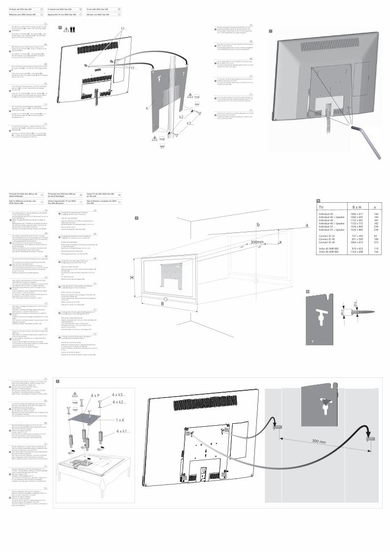
88Linie a zeigt die Oberkante des TV-GerätesLinie b gibt die Mitte des TV-Gerätes an
Höhe der Linie a festlegen
Lage der 2 Bohrlöcher mit Hilfe von Skizzen (8) und Tabelle (8a) bestimmenAlle Maßangaben und Geräteabmaße (B x H) in mm
Halteschrauben setzen
Halteschraubengröße, siehe Skizze (8b)
l
8Lijn a geeft de bovenkant van het tv-toestel aanLijn b geeft het midden van het tv-toestel aan
Hoogte van lijn a bepalen
Positie van de 2 boorgaten met behulp van tekeningen (8) en tabel (8a) bepalenAlle maten en toestelafmetingen (B x H) in mm
Bevestigingsschroeven aanbrengen
Bevestigingsschroefmaat, zie tekening (8b)
g
8Line a shows the upper edge of the TV setLine b indicates the centre of the TV set
Determine height of line a
Determine position of the 2 holes using the diagrams (8) and table (8a)All dimensional data and device dimensions (W x H) in mm
Set retaining screws
Retaining screw size, see diagram (8b)
f
8La ligne a indique la limite supérieure du téléviseurLa ligne b indique le milieu du téléviseur
Dé nir la hauteur de la ligne a
Déterminer la position des 2 perçages à l'aide des sché-mas (8) et du tableau (8a)Toutes indications de mesure et dimensions d'appareil (L x H) en mmMettre en place les vis d'arrêt
Taille des vis d'arrêt, voir schéma (8b)
i
8La linea a indica il bordo superiore dell'apparecchio TVLa linea b indica il centro dell'apparecchio TV
Determinare l'altezza della linea aStabilire la posizione dei 2 fori con l'ausilio dei disegni (8) e della tabella (8 a)Tutti i dati relativi alle misure e le dimensioni dell'apparecchio (larg. x alt.) sono indicati in mmInserire le viti di arresto
Dimensioni delle viti di arresto, vedi disegno (8 b)
e
8La línea a muestra el borde superior del televisorLa línea b señala la mitad del televisor
Determinar el alto de la línea a
Determinar la posición de los 2 agujeros de perforación con ayuda de los croquis (8) y la tabla (8a)Todas las medidas y dimensiones del aparato (A x A) están en mm
Colocar los tornillos de jación
Tamaño de los tornillos de jación, véase el croquis (8b)
12
6
300 mm
67
8
8b8b
8a8a
TV B x H x
Individual 40 ... 1000 x 617 144Individual 40 + Speaker 1000 x 697 144Individual 46 ... 1133 x 692 182Individual 46 + Speaker 1133 x 772 182Individual 55 ... 1326 x 805 238Individual 55 + Speaker 1326 x 883 238
Connect ID 32 747 x 494 93Connect ID 40 931 x 599 198Connect ID 46 1064 x 674 273
Xelos 40 (MB180) 970 x 623 119Xelos 46 (MB180) 1103 x 698 156
9