trc-700 - fenix stageen).pdf · fenix stage, s.l. dirección: avda. de los trabajadores, 24 - horno...
TRANSCRIPT

TRC-700
LIFTING TOWERS
Nº de serie:Serial No.:
Instrucciones
Instructions
Fabricante:Manufacturer:
FENIX Stage, S.L.Avda. de los Trabajadores, 24Horno de Alcedo46026 - Valencia (Spain)Tel.: +34 96 125 08 [email protected]
22
DECLARACION DE CONFORMIDAD
La Dirección de la empresa:
FENIX STAGE, S.L. Dirección: Avda. de los Trabajadores, 24 - Horno de Alcedo - 46026 - Valencia (España) Teléfono/fax: +34 96 125 08 55 / +34 96 125 13 05 CIF: B-91423046
Declaramos bajo nuestra exclusiva responsabilidad la conformidad del producto:
Nombre: TORRE ESTRUCTURAL
Modelo: TRC-700
Descripción:
Tubo principal: 50 x 3mm.
Tubo secundario: 20 x 2mm.
Altura máxima: 7m.
Carga máxima: 600kg.
Material: acero según EN 10305-5.
aluminio EN-AW 6082-T6.
Área de la base: 2,02 x 1,77m.
Tipo de Truss: SQRE-29.
Peso: 193kg.
al que se refiere esta declaración, con las disposiciones de la normativa de maquinaria CE
2006/42/EG y sus modificaciones.
Persona facultada para elaborar el expediente técnico y representante autorizado: Mª Julia Niza del Río
Número de serie:
Fecha:
3
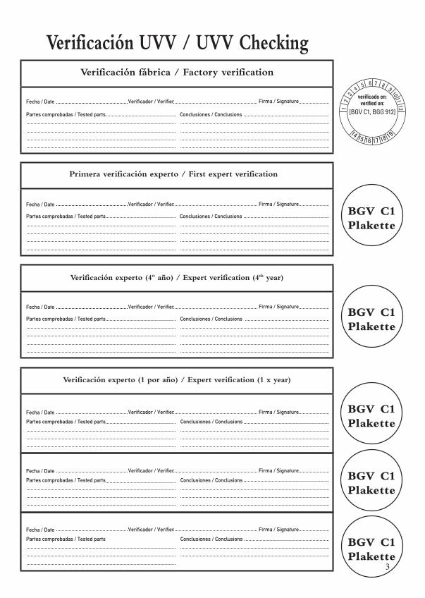
Verificación fábrica / Factory verification
Fecha / Date Verificador / Verifier Firma / Signature
Fecha / Date Verificador / Verifier Firma / Signature
Fecha / Date Verificador / Verifier Firma / Signature
Partes comprobadas / Tested parts Conclusiones / Conclusions
Partes comprobadas / Tested parts Conclusiones / Conclusions
Verificación UVV / UVV Checking
Partes comprobadas / Tested parts Conclusiones / Conclusions
Fecha / Date Verificador / Verifier Firma / Signature
Partes comprobadas / Tested parts Conclusiones / Conclusions
Fecha / Date Verificador / Verifier Firma / Signature
Partes comprobadas / Tested parts Conclusiones / Conclusions
Fecha / Date Verificador / Verifier Firma / Signature
1 2
3 4
5 6 7 8 9 10 11 12
14 15 16 17 18 19
[BGV C1, BGG 912]
verificado en:verified on:
Primera verificación experto / First expert verification
Partes comprobadas / Tested parts Conclusiones / Conclusions
Verificación experto (4º año) / Expert verification (4th year)
Verificación experto (1 por año) / Expert verification (1 x year)
44
ÍNDICE
1.- INTRODUCCIÓN 7
2.- DATOS GENERALES 7
2.1.- Datos técnicos 7
2.2.- Normativa de aplicación 7
3.- NORMAS DE SEGURIDAD 8
4.- INSTRUCCIONES DE USO 9
5.- MANTENIMIENTO 9
6.- RIESGOS ESPECÍFICOS 10
7.- SISTEMAS DE PREVENCIÓN 10
INDEX
1.- INTRODUCTION 11
2.- GENERAL DATA 11
2.1.- Technical data 11
2.2.- Applicable regulations 11
3.- GENERAL SAFETY RULES 12
4.- HOW TO USE 13
5.- MAINTENANCE 13
6.- SPECIFIC RISKS 14
7.- PREVENTION SYSTEMS 14
55
ESPAÑOL1. INTRODUCCIÓN
El presente manual de instrucciones ha sido realizado en conformidad con los requisitos de la Directiva de Máquinas CE 2006/42/EC y sus sucesivas modificaciones.El manual de instrucciones representa parte integrante de la Torre Estructural. Debe ser consultado antes, durante y después de la puesta en marcha de la torre así como cada vez que se considere necesario, respetando su contenido en todas y cada una de sus partes.Solamente de este modo se podrán alcanzar los objetivos fundamentales que se han establecido en la base de este manual como son prevenir riesgos de accidentes y optimizar lo máximo posible las prestaciones de la torre estructural.En el marco de dicho manual se han cuidado minuciosamente los aspectos correspondientes a la seguridad y a la prevención de accidentes en el trabajo durante la utilización de la máquina destacando las informaciones que son de mayor interés para el usuario.
ATENCIÓN: ANTES DE UTILIZAR LA TORRE ESTRUCTURAL,
LEA ATENTAMENTE ESTE MANUAL
2. DATOS GENERALES
2.1. Datos técnicos:
Denominación: TORRE ESTRUCTURAL
Modelo: TRC-700
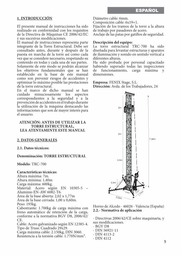
Características técnicas:Altura máxima: 7m.Altura mínima: 1,40mCarga máxima: 600kg.Material: Acero según EN 10305-5 – Aluminio EN-AW 6082-T6.Área de la base abierta: 2,02 x 1,77mÁrea de la base cerrada: 1,00 x 0,60m.Peso: 193kg.Cabestrante: 1.700kg de carga máxima con freno automático de retención de la carga, conforme a la normativa BGV D8, 2006/42/CE.Cable: Acero galvanizado según EN 12385-4.Tipo de Truss: Cuadrado 29x29.Carga máxima cable: 2.150kg, DIN 3060.Resistencia a la torsión cable: 1.770N/mm².
Diámetro cable: 6mm. Composición cable: 6x19+1. Fijación de los tramos de la torre a la altura de trabajo por pasadores de acero.Anclaje de las patas por gatillos de seguridad.
Descripción del equipo:La torre estructural TRC-700 ha sido diseñada para levantar estructuras y aparatos de iluminación y sonido en sentido vertical a diferentes alturas.Ha sido probada por personal capacitado habiendo superado todas las inspecciones de funcionamiento, carga máxima y dimensiones.
Empresa: FENIX Stage, S.L. Dirección: Avda. de los Trabajadores, 24
Horno de Alcedo - 46026 - Valencia (España)2.2.- Normativa de aplicación
- Directivas 2006/42/CE sobre maquinaria, y sus modificaciones.- BGV D8 - DIN 56921-11- DIN 4113-2- DIN 4112
2m
2m
2,5m
1,77m
2,02m
7,46m
0,995m 0,595
m
0,5m
66
ESPAÑOL3. NORMAS GENERALES DE SEGURIDAD
- La torre estructural es un elemento industrial diseñado para la elevación de cargas en sentido vertical, nunca se debe utilizar como plataforma estructural de personas.
- Colocar la torre estructural sólo en superficies duras y planas, verificando que está en posición vertical. Nunca utilice cuñas ni elementos extraños para equilibrar la torre estructural.
- Comprobar que las patas están correctamente montadas y sujetas por sus pasadores retenedores de seguridad.
- Nunca se debe elevar una carga sin antes verificar que está correctamente apoyada y centrada en los soportes elevadores adecuados, de forma que el peso de la carga sólo actúe en sentido vertical.
- No se debe sobrepasar la capacidad de carga máxima indicada en la etiqueta de características de la torre estructural y en este manual de instrucciones.
- Si existe posibilidad de viento fuerte o en ráfagas, coloque la torre estructural en suelo firme y asegúrelo con la ayuda de tirantes.
- Nunca fije un tirante sobre un vehículo ni cualquier otro elemento que pueda desplazarse.
- No usar escaleras encima de la torre estructural ni apoyarlas en él para realizar ningún tipo de trabajo.
- Tenga cuidado con todo tipo de salientes por encima de la torre estructural como cornisas, balcones, letreros luminosos, etc. Es muy importante evitar la presencia de cables por debajo de la altura de trabajo del elevador.
- Nunca se debe desplazar la torre estructural si ésta se encuentra con la carga elevada. No es aconsejable realizar ningún tipo de movimiento, ni tan siquiera pequeños ajustes de posicionamiento.
- Nunca utilizar la torre estructural sobre ninguna superficie móvil o vehículo.
- Antes de utilizar la torre elevadora, verificar el estado del cable, éste no debe presentar rotura de hilos o aplastamiento. No usar nunca cables defectuosos y en caso de duda cambie el cable. Sólo utilice cable de acero según describe este manual.
- Fijar o quitar la manivela cuando la carga esté elevada.
- Para el transporte de la torre estructural hay que desmontar todos los tramos.
77
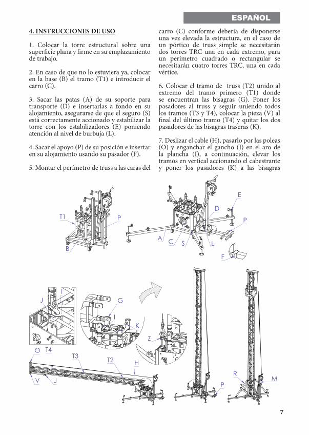
ESPAÑOL4. INSTRUCCIONES DE USO
1. Colocar la torre estructural sobre una superficie plana y firme en su emplazamiento de trabajo.
2. En caso de que no lo estuviera ya, colocar en la base (B) el tramo (T1) e introducir el carro (C).
3. Sacar las patas (A) de su soporte para transporte (D) e insertarlas a fondo en su alojamiento, asegurarse de que el seguro (S) está correctamente accionado y estabilizar la torre con los estabilizadores (E) poniendo atención al nivel de burbuja (L).
4. Sacar el apoyo (P) de su posición e insertar en su alojamiento usando su pasador (F).
5. Montar el perímetro de truss a las caras del
carro (C) conforme debería de disponerse una vez elevada la estructura, en el caso de un pórtico de truss simple se necesitarán dos torres TRC una en cada extremo, para un perímetro cuadrado o rectangular se necesitarán cuatro torres TRC, una en cada vértice.
6. Colocar el tramo de truss (T2) unido al extremo del tramo primero (T1) donde se encuentran las bisagras (G). Poner los pasadores al truss y seguir uniendo todos los tramos (T3 y T4), colocar la pieza (V) al final del último tramo (T4) y quitar los dos pasadores de las bisagras traseras (K).
7. Deslizar el cable (H), pasarlo por las poleas (O) y enganchar el gancho (J) en el aro de la plancha (I), a continuación, elevar los tramos en vertical accionando el cabestrante y poner los pasadores (K) a las bisagras
T2T3T4
H
O
JV
PM
R
IK
G
Z
IJ
B
PT1
A
E
S
D
C L
P
F
88
ESPAÑOLuna vez elevado. En el caso de que el carro no tenga montado truss en la dirección de elevación del truss tumbado (T2, T3 & T4), se necesitará una carga mínima estable de 90kg en el apoyo (P) para la elevación del truss.
8. Una vez elevado el truss y con los pasadores de las bisagras (K) puestos, enganchar el gancho (J) en el grillete del carro (Z) después, elevar el carro haciendo uso de la manivela del cabestrante (M).
9. Con el carro subido a media altura, poner los tirantes (R) y continuar subiendo a la altura deseada. Tras esto, para asegurar la torre, se aconseja quitar la manivela (M) del cabestrante.
10. Para cambiar o añadir puntas de conexión al carro se recomienda quitar el carro de la torre, desatornillar los conectores con una llave de 19 allen y volver a atornillar en la posición correspondiente.
11. Para el proceso de bajada y plegado, invertir el orden de los pasos descritos.
ATENCIÓN:RECOMENDAMOS MONTAR EL PERÍMETRO A LAS CARAS DEL CARRO ANTES DE ELEVAR LAS
TORRES
5. MANTENIMIENTO
1. Comprobar periódicamente el estado del cable. Si un cable presenta rotura de hilos o aplastamiento, debe ser sustituido inmediatamente por otro nuevo. No utilizar la torre estructural con cables en mal estado.Utilizar solamente cable de acero DIN 3060 resistente a la torsión.
2. La torre estructural se suministra completamente engrasada de fábrica. No obstante, se recomienda engrasar periódicamente según el uso, la corona dentada del cabestrante, los cojinetes del árbol de accionamiento y el buje, la rosca de la manivela y los tramos.
ATENCIÓN:NO ENGRASAR NI LUBRICAR EL
MECANISMO DEL FRENOLos discos de freno, han sido engrasados con una grasa especial resistente al calor y la presión. No deben ser utilizados otros productos para evitar influir negativamente en el funcionamiento del freno. No es necesario engrasar los discos de freno.
3. La torre estructural debe ser comprobada por un experto como mínimo una vez al año de acuerdo con su utilización.
4. Solamente deben utilizarse piezas de repuesto originales para garantizar una continuada seguridad de uso.
5. El usuario pierde todos los derechos de garantía, si incorpora otros repuestos que no sean originales o lleva a cabo cualquier modificación en el producto.
6. RIESGOS ESPECÍFICOS
Fallo del sistema de freno
Puede producirse por deficiencias en el sistema de frenado o por una mala instalación. Si deja de funcionar puede provocar un riesgo importante de pérdida de control de la mercancía elevada y originar golpes y/o contusiones sobre los usuarios o golpes sobre los materiales que se encuentren próximos a la torre.
Pérdida de estabilidad
Si se coloca la torre sobre un terreno inclinado o sobre una superficie que no sea completamente lisa existe el riesgo de pérdida de estabilidad lo que daría lugar generalmente a un vuelco de 90º con riesgo de lesiones graves para los operarios.
Caída de objetos a distinto nivel
Como elemento de elevación, su trabajo en altura hace que haya un riesgo importante de caída a diferente nivel de los objetos elevados, bien por fallo de los mecanismos de sujeción, desgaste de piezas, suciedad, etc. bien por utilización incorrecta de la torre (Ej: para elementos por encima de la carga
99
ESPAÑOLmáxima permitida). El descenso brusco del material elevado supone un elevado riesgo para el operario.Golpes y/o contusiones por objetos
Este riesgo tan sólo en contadas ocasiones se traduce en accidente para el operario que conduce la operación, dada su situación durante el proceso de elevación; el riesgo de golpes por el elemento sobreelevado puede más bien afectar a personas que deambulen o tengan su puesto de trabajo en zonas cercanas a la torre estructural.
Su origen puede ser debido a pérdida de estabilidad, mal funcionamiento de elementos estructurales, mal funcionamiento de sistemas de seguridad, sistemas de sujeción, etc.
7. SISTEMAS DE PREVENCIÓN
Sobre fallo del sistema de freno
Disponer de cabestrante conforme a la norma BGV D8 y 2006/42/CE.
Sobre pérdida de estabilidad
El mantenimiento de la estabilidad de la torre estructural debe realizarse básicamente con las siguientes medidas: • Profesionalización, adiestramiento, formación y concienciación del riesgo a los usuarios de las torres.• Dotación de diferentes dispositivos de seguridad y consejos por parte del fabricante, para reforzar su estabilidad como por ejemplo: - Pasadores de seguridad que fijan la torre una vez elevada.- Nivel de burbuja para facilitar el ajuste vertical.- Marcado de la carga máxima que puede elevar la torre.- Especificación de la pendiente máxima a la que pueden acceder las torres de forma segura. Sobre caída de objetos a distinto nivel, golpes y/o contusiones con objetos
El riesgo de caída de objetos a distinto nivel puede prevenirse con la utilización de
elementos de seguridad homologados, por ejemplo, un gatillo de seguridad que fije el tramo interior de la torre en su posición de trabajo, de forma que el cable no soporta la carga y se garantiza la imposibilidad de una caída. En caso de rotura de cable, actúa el freno automáticamente. Por otra parte, si los elementos de acero están zincados se protege el conjunto de la oxidación y la corrosión.
También se pueden minimizar estos riesgos con un adecuado mantenimiento de la torre estructural. El usuario deberá hacer inspec-ciones periódicas de los elementos de seguri-dad y realizar las reparaciones necesarias en caso de detectar deficiencias.
Asimismo, se pueden reducir las consecuen-cias de estos riesgos limitando la zona de acceso a la torre estructural y con adecuada formación del personal.
Otras consideraciones
Este equipo no emite más de 80 dB.
1010
ENGLISH1. INTRODUCTION
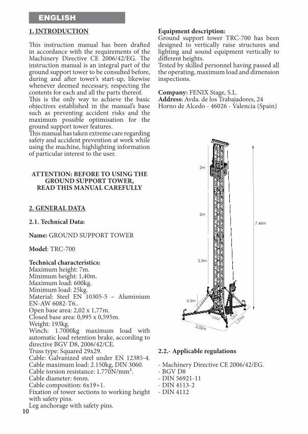
This instruction manual has been drafted in accordance with the requirements of the Machinery Directive CE 2006/42/EG. The instruction manual is an integral part of the ground support tower to be consulted before, during and after tower’s start-up, likewise whenever deemed necessary, respecting the contents for each and all the parts thereof.This is the only way to achieve the basic objectives established in the manual’s base such as preventing accident risks and the maximum possible optimisation for the ground support tower features.This manual has taken extreme care regarding safety and accident prevention at work while using the machine, highlighting information of particular interest to the user.
ATTENTION: BEFORE TO USING THE GROUND SUPPORT TOWER,
READ THIS MANUAL CAREFULLY
2. GENERAL DATA
2.1. Technical Data:
Name: GROUND SUPPORT TOWER
Model: TRC-700
Technical characteristics:Maximum height: 7m.Minimum height: 1,40m.Maximum load: 600kg.Minimum load: 25kg.Material: Steel EN 10305-5 – Aluminium EN-AW 6082-T6..Open base area: 2,02 x 1,77m.Closed base area: 0,995 x 0,595m.Weight: 193kg.Winch: 1.7000kg maximum load with automatic load retention brake, according to directive BGV D8, 2006/42/CE.Truss type: Squared 29x29.Cable: Galvanized steel under EN 12385-4. Cable maximum load: 2.150kg, DIN 3060.Cable torsion resistance: 1.770N/mm².Cable diameter: 6mm.Cable composition: 6x19+1.Fixation of tower sections to working height with safety pins.Leg anchorage with safety pins.
Equipment description:Ground support tower TRC-700 has been designed to vertically raise structures and lighting and sound equipment vertically to different heights.Tested by skilled personnel having passed all the operating, maximum load and dimension inspections.
Company: FENIX Stage, S.L. Address: Avda. de los Trabajadores, 24Horno de Alcedo - 46026 - Valencia (Spain)
2.2.- Applicable regulations
- Machinery Directive CE 2006/42/EG.- BGV D8 - DIN 56921-11- DIN 4113-2- DIN 4112
2m
2m
2,5m
1,77m
2,02m
7,46m
0,995m 0,595
m
0,5m
1111
ENGLISH3. GENERAL SAFETY RULES
- The ground support tower is an industrial element designed to raise loads vertically, it must never be used as a platform elevator for people.
- Only place the ground support tower on firm flat grounds checking it is in vertical position. Do not use wedges or any strange elements to balance the ground-support tower.
- Check legs are correctly assembled and secured by their safety pins.
- Never raise a load without first checking it is correctly supported and centred on the appropriate ground support tower supports, so the load only acts vertically.
- Never surpass the maximum load capacity indicated on the ground support tower characteristics label and on this instruction manual.
- If there is a likelihood of strong wind or gusts, place the ground support tower on the ground and secure it with the aid of straps.Never fix a strap over a vehicle or any other element which might move.
- Never use a ladder over the ground support tower or lean against it for any kind of work.
- Beware of any kind of projection above the ground support tower like cornices, balconies, luminous signs, etc. It is very important to avoid the presence of cables below the ground support tower’s working height.
- Never move the ground support tower when the load is raised. It is inadvisable to make any kind of movement, even small positioning adjustments.
- Never use the ground support tower over any mobile surface or vehicle.
- Before using the ground support tower, check the cable’s state, which must not present any broken threads or compression. Never use defective cables and change cable if in doubt. Only use steel cable as described on this manual.
- Fix the lever when the load is raised.
- All sections of the ground support tower must be lowered to transport it.
1212
ENGLISH4. HOW TO USE
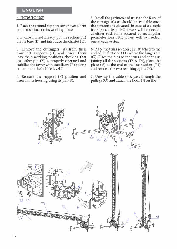
1. Place the ground support tower over a firm and flat surface on its working place.
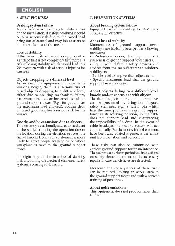
2. In case it is not already, put the section(T1) on the base (B) and introduce the chariot (C).
3. Remove the outriggers (A) from their transport supports (D) and insert them into their working positions checking that the safety pin (K) is properly operated and stabilize the tower with stabilizers (E) paying attention to the bubble level (L).
4. Remove the support (P) position and insert in its housing using its pin (F).
5. Install the perimeter of truss to the faces of the carriage (C) as should be available once the structure is elevated, in case of a simple truss porch, two TRC towers will be needed at either end, for a squared or rectangular perimeter four TRC towers will be needed, one at each vertex.
6. Place the truss section (T2) attached to the end of the first one (T1) where the hinges are (G). Place the pins to the truss and continue joining all the sections (T3 & T4), place the piece (V) at the end of the last section (T4) and remove the two rear hinge pins (K).
7. Unwrap the cable (H), pass through the pulleys (O) and attach the hook (J) on the
T2T3T4
H
O
JV
PM
R
IK
G
Z
IJ
B
PT1
A
E
S
D
C L
P
F
1313
ENGLISHrim of the plate (I), then raise the sections vertically by operating the winch and put the pins (K) to the hinges once elevated. In the event that the carriage does not have mounted truss lying in the lifting direction of the truss (T2, T3 & T4), a stable minimum load of 90kg at the support (P) for lifting the truss will be required.
8. Once the truss is raised with the pins places on the hinges (K), engage the hook (J) on the shackle of the carriage (Z) then raise the it using the winch handle (M).
9. With the carriage lifted halfway up, put the straps (R) and continue lifting up to the desired height. After that, to ensure the tower, you are advised to remove the handle (M) from the winch.
10. To change or add points of connection to the car, it is advised to remove the carriage from the tower, unscrew the connectors with an allen wrench size 8 and then screw again in the corresponding position.
11. For the process of lowering and folding, reverse the order of the steps.
ATTENTION: WE RECOMMEND ASSEMBLING THE PERIMETER TO THE FACES OF THE CARRIAGE BEFORE RAISING THE
TOWER
5. MAINTENANCE
1. Periodically check cable status. If the cable seems to have broken wires or crushing, replace immediately with a new one. Never use the ground support tower with cables in bad conditions. Only use galvanized steel under EN 12385-4. Cable maximum load: 2.000kg. Cable torsion resistance: 1.770N/mm². Cable diameter: 6mm. Cable composition: 6x19+1.
2. The ground support tower is supplied fully greased from factory. Nevertheless, the crown gear of the winch, to the threaded bar of the stabiliser outriggers and the profiles, because of its use periodical greasing is recommended.
WARNING:DO NOT GREASE OR LUBRICATE
BRAKING MECHANISM
Braking disks were greased with a special heat and pressure resistant grease. No other product must be used to prevent negative influence on brake functioning.
3. Ground support tower TRC-700, must be checked by an expert a minimum of once a year as per its use.
4. Only original spare parts must be used to ensure continued safe use. The user loses all guarantee rights if spare parts other than the originals are incorporated or the product is modified in any way.
5. To request any spare part, contact the manufacturer or an authorised distributor within your territory.
1414
ENGLISH6. SPECIFIC RISKS
Braking system failureMay occur due to braking system deficiencies or bad installation. If it stops working it could cause a serious risk due to the raised load being out of control and may injure users or hit materials next to the tower.
Loss of stabilityIf the tower is placed on a sloping ground or a surface that is not completely flat, there is a risk of losing stability which would lead to a 90º overturn with risk of serious injuries for workers.
Objects dropping to a different levelAs an elevation equipment and due to its working height, there is a serious risk of raised objects dropping to a different level, either due to securing mechanism failure, part wear, dirt, etc., or incorrect use of the ground support tower (E.g.: for goods over the maximum load allowed). Sudden drop of raised goods implies a serious risk for the worker.
Knocks and/or contusions due to objectsThis risk only occasionally causes an accident to the worker running the operation due to his location during the elevation process; the risk of knocks from a raised element is more likely to affect people walking by or whose workplace is next to the ground support tower.
Its origin may be due to a loss of stability, malfunctioning of structural elements, safety systems, securing systems, etc.
7. PREVENTION SYSTEMS
About braking system failureEquip with winch according to BGV D8 y 2006/42/CE directive.
About loss of stabilityMaintenance of ground support tower stability must basically be as per the following measures: • Professionalization, training and risk awareness of ground support tower users.• Equip with different safety devices and advices from the manufacturer to reinforce stability, as: - Bubble level to help vertical adjustment.- Specify maximum load that the ground support tower can raise.
About objects falling to a different level, knocks and/or contusions with objectsThe risk of objects falling to a different level can be prevented by using homologated safety elements, e.g., a safety pin which fixes the inner profile of the ground support tower in its working position, so the cable does not support load and guaranteeing the impossibility of a drop. In the event of cable breakage, the braking system will act automatically. Furthermore, if steel elements have been zinc coated it protects the entire unit from oxidation and corrosion.
These risks can also be minimised with correct ground support tower maintenance. The user must perform periodical inspections on safety elements and make the necessary repairs in case deficiencies are detected.
Moreover, the consequences of these risks can be reduced limiting an access area to the ground support tower and with a correct training of personnel.
About noise emissionsThis equipment does not produce more than 80 dB.
15
T2
T1
16
3075
11101406
1308
2044
13081091
3070
1054
1310
3095
3104
1310
4100
4101
13081406
4102
1813
1815
4105
1850
1825
1864
31181417
1109
2500
3110
3111
10913116
4109
1818
1800
3121
3112
1091
1096
3120
4110
3115
1790
1416
1091
1810
4120
1865
1860
4103
1037
41214123
4122
4124
11151091
4031
1170,1312,1410
1308
1132,1306
1017,1402,1304
3412
1410
3057
T1
17
2503 x2
3113
1810 1790
1308
3112
1039
3057
4106 1049
30101310
1815
1813
2865 3427
12523426
4030
1028
30441305
20521305
13021004
3069
3042
1021
4203
28643462
2504x1
2340
4250
18141811
1066
T2
1314

18
NOTAS / NOTES
LIFTING TOWERS

19
NOTAS / NOTES
LIFTING TOWERS

FENIX Stage, S.L.Avda. de los Trabajadores, 24
Horno de Alcedo46026 - Valencia (España)
Tel.: +34 96 125 08 [email protected]
www.fenixstage.com