tipos de órbitas.docx
TRANSCRIPT

8112019 Tipos de oacuterbitasdocx
httpslidepdfcomreaderfulltipos-de-orbitasdocx 130
Tipos de oacuterbitas
Una forma de diferenciar los sistemas de sateacutelites es por la altura a la que se encuentra la oacuterbita por la quecirculan ademaacutes eacutesta tambieacuten influiraacute de forma decisiva a la hora de obtener el nuacutemero de sateacutelites necesario
para conseguir la cobertura deseada Dado cierto ancho de haz el aacuterea de cobertura seraacute mucho menor estandoen una oacuterbita baja que en otra de mayor altura Por otro lado la potencia necesaria para emitir desde oacuterbitas
bajas es menor con los inconvenientes que ello conlleva Entonces se intentaraacute alcanzar un compromiso quenos de una relativamente buena zona de cobertura y una potencia de transmisioacuten lo menor posible
Se pueden diferenciar cutro tipos de oacuterbitas seguacuten sus altitudes
GEO Oacuterbitas Terrestres Geosiacutencronas tambieacuten conocida como oacuterbita de Clarke en honor al escritorArthur Clarke que escribioacute en 1945 por primera vez de esta posibilidad La oacuterbita GEO estaacute situada a35848 Km De altura con una latitud de 0 grados es decir situada sobre el Ecuador El periacuteodo de estaoacuterbita es de exactamente 24 horas y por lo tanto estaraacute siempre sobre la misma posicioacuten relativarespecto a la Tierra La mayoriacutea de los sateacutelites actuales son GEO Los sateacutelites GEO (sateacutelites queviajan en oacuterbitas GEO) precisan menos cantidad de ellos para cubrir la totalidad de la superficieterrestre pero poseen un retardo de 024 seg Por diacutea de ahiacute que no tardan exactamente un diacutea encubrir una vuelta entera a la Tierra debido al camino de ida y de vuelta que debe recorrer la sentildeal Lossateacutelites GEO necesitan tambieacuten obtener unas posiciones orbitales especiacuteficas alrededor del Ecuador
para mantenerse lo suficientemente alejados unos de otros (unos 2 grados aproximadamente) paraevitar posibles interferencias intersateacutelite La ITU y la FCC se encargan de administrar estas
posiciones MEO Oacuterbita Terrestre Media Se encuentran a una altura de entre 10075 y 20150 Km A diferencia de
los GEO su posicioacuten relativa respecto a la Tierra no es fija Debido a su menor altitud se necesitaraacutenmaacutes sateacutelites para cubrir la superficie terrestre pero pro contra se reduce la latencia del sistema deforma significativa En la actualidad no existen muchos MEO y se utilizan principalmente para
posicionamiento LEO Oacuterbita Terrestre de Baja altura Los sateacutelites encauzados en este tipo de oacuterbitas son de tres tipos
LEO pequentildeos (centenares de Kbps) destinados a aplicaciones de bajo ancho de banda LEO grandes(miles de Kbps) albergan las aplicaciones de los anteriores y otras como telefoniacutea moacutevil y transmisioacutende datos y finalmente los LEO de banda ancha (megaLEO) que operan en la banda de Mbps entre losque se encuentre Teledesic La puesta en oacuterbita de sateacutelites LEO presenta problemas tales como
1 Saturacioacuten de las oacuterbitas elevada cantidad de sateacutelites ya existentes en esa zona yelevado nuacutemero de proyectos de lanzamientos de sateacutelites de este tipo
2 Chatarra espacial dificultadas para la buena circulacioacuten debido a restos de otrossateacutelites en la zona
3 Peacuterdida y sustitucioacuten de sateacutelites cabe la posibilidad de que estos sateacutelites caigan enla atmoacutesfera al terminar su vida uacutetil y se desintegren en la misma Ademaacutes habraacute quetener en cuenta una poliacutetica de sustitucioacuten de este tipo de sateacutelites pues estaacutenexpuestos a muacuteltiples peligros incluso antes del final de su vida uacutetil
4 Visibilidad del sateacutelite se debe poder seguir la pista a estos sateacutelites que viajan agran velocidad luego este tipo de sateacutelites soacutelo seraacute visible 18-20 min antes deaparecer por el horizonte
5 Problema de la antena se resuelve utilizando una antena del tipo array en fase queson dispositivos autodirigidos capaces de seguir el rastro de varios sateacutelites a la vezsin moverse fiacutesicamente por medio de sentildeales levemente diferentes recibidas en laantena Con este tipo de antenas desaparece el problema de mantener un enlaceactivo cuando perdemos la visioacuten del sateacutelite manteniendo como miacutenimo dossateacutelites a la vista en todo momento siendo la antena consciente de iniciar un nuevo
8112019 Tipos de oacuterbitasdocx
httpslidepdfcomreaderfulltipos-de-orbitasdocx 230
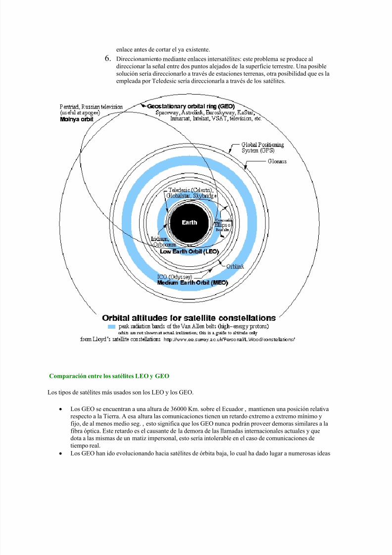
enlace antes de cortar el ya existente 6 Direccionamiento mediante enlaces intersateacutelites este problema se produce al
direccionar la sentildeal entre dos puntos alejados de la superficie terrestre Una posiblesolucioacuten seriacutea direccionarlo a traveacutes de estaciones terrenas otra posibilidad que es laempleada por Teledesic seriacutea direccionarla a traveacutes de los sateacutelites
Comparacioacuten entre los sateacutelites LEO y GEO
Los tipos de sateacutelites maacutes usados son los LEO y los GEO
Los GEO se encuentran a una altura de 36000 Km sobre el Ecuador mantienen una posicioacuten relativarespecto a la Tierra A esa altura las comunicaciones tienen un retardo extremo a extremo miacutenimo yfijo de al menos medio seg esto significa que los GEO nunca podraacuten proveer demoras similares a lafibra oacuteptica Este retardo es el causante de la demora de las llamadas internacionales actuales y quedota a las mismas de un matiz impersonal esto seriacutea intolerable en el caso de comunicaciones detiempo real
Los GEO han ido evolucionando hacia sateacutelites de oacuterbita baja lo cual ha dado lugar a numerosas ideas
8112019 Tipos de oacuterbitasdocx
httpslidepdfcomreaderfulltipos-de-orbitasdocx 330
sobre sistemas de sateacutelites globales los cuales los podremos agrupar seguacuten la siguiente tabla
Tipo de sistema LEO pequentildeo LEO grande LEO de banda ancha
Ejemplo Orbcomm VITA Iridium Globalstar ICO Teledesic
Complemento terrestre Radiobuacutesqueda Celular Fibra oacuteptica
Frecuencia lt1 GHz 1 - 3 GHz 3020 GHz
Los principios del posicionamiento GPS
El sistema de control estaacute constituido por un conjunto de estaciones permanentes con
coordenadas bien conocidas en un sistema terrestre de referencia internacionalmente
aceptado Su misioacuten es la de rastrear a todos los sateacutelites para calcular las oacuterbitas (efemeacuterides)
y controlar sus relojes
El sistema espacial estaacute constituido por la constelacioacuten de sateacutelites (nominalmente 24 activos)
Cada sateacutelite lleva a bordo varios relojes atoacutemicos (5) para asegurar la exactitud de las marcas
de tiempo y la estabilidad de la frecuencia de la sentildeal emitida
Los usuarios equipados con receptores de las sentildeales satelitales reciben simultaacuteneamente las
componentes de la sentildeal que sirven para medir la distancia receptor-sateacutelite y el mensaje de
navegacioacuten ppalmente constituido por las efemeacuterides que permiten calcular las coordenadas
de los sateacutelites
8112019 Tipos de oacuterbitasdocx
httpslidepdfcomreaderfulltipos-de-orbitasdocx 430
SA viene de Selective Availability y consiste en una degradacioacuten intencional de relojes y
efemeacuterides para usuarios ldquono calificadosrdquo Desactivada
La atmoacutesfera introduce errores en la propagacioacuten de la sentildeal de difiacutecil modelizacioacuten (orden
metros)
El reloj del receptor deberiacutea estar sincronizado con el tiempo de los sateacutelites Se elimina
agregando una nueva incoacutegnita a la ecuacioacuten (1)
Ri = ((Xi ndash Xu)2 + (Yi ndash Yu)
2 + (Zi ndash Zu)
2 )frac12 + cdt
Las oacuterbitas trasmitidas son extrapoladas introducen errores del orden del metro
8112019 Tipos de oacuterbitasdocx
httpslidepdfcomreaderfulltipos-de-orbitasdocx 530
bull La SA la degradacioacuten de los relojes satelitales afecta estriacutectamente igual a las dos estaciones
los errores en las efemeacuterides (oacuterbitas) son importantes si la distancia entre las estaciones es
muy grande (maacutes de 50 km) En tal caso se utilizan efemeacuterides precisas
bull La atmoacutesfera introduce errores muy similares para distancias de algunas decenas de km Para
distancias mayores es importante utilizar receptores de doble frecuencia para eliminar los
errores de la ionoacutesfera
bull Es condicioacuten necesaria para alcanzar una solucioacuten apropiada contar con una buena posicioacuten de
partida de lo contrario la precisioacuten de la posicioacuten relativa resultaraacute afectada seguacuten una regla
aproximada
bull Error en la base =gt 1 PPM cada 10 m de error en las coordenadas de partida
bull La atmoacutesfera perturba la propagacioacuten de las sentildeales GPS
bull Los efectos son diferentes en la Ionoacutesfera (capa superior por encima de 80 km) y en la
Tropoacutesfera (capa inferior hasta 11 km)
La ionoacutesfera afecta a las sentildeales en forma inversamente proporcional a la frecuencia de las
mismas Esto permite eliminar su efecto combinando las componentes de las sentildeales GPS en
8112019 Tipos de oacuterbitasdocx
httpslidepdfcomreaderfulltipos-de-orbitasdocx 630
las dos frecuencias posibles L1 y L2 Para ello es necesario utilizar receptores de ldquodoble
frecuenciardquo
La tropoacutesfera (baja atmoacutesfera) introduce errores importantes al producir un retardo en la
sentildeal Se modeliza muy aceptablemente la componente seca y con maacutes incertidumbre la
componente huacutemeda (influencia del vapor de agua en el camino de la onda)
Afecta principalmente la determinacioacuten de alturas con GPS
DOP viene de ldquoDilucioacuten de la Precisionrdquo es decir que es un factor que multiplica a la
precisioacuten de las mediciones desmejorando la precisioacuten real
Oslash Cuanto mayor es el PDOP maacutes desfavorable es la situacioacuten
Oslash Este es un indicador que puede predecirse con una planificacioacuten apropiada
Otros indicadores son HDOP VDOP TDOP
8112019 Tipos de oacuterbitasdocx
httpslidepdfcomreaderfulltipos-de-orbitasdocx 730
8112019 Tipos de oacuterbitasdocx
httpslidepdfcomreaderfulltipos-de-orbitasdocx 830
8112019 Tipos de oacuterbitasdocx
httpslidepdfcomreaderfulltipos-de-orbitasdocx 930
8112019 Tipos de oacuterbitasdocx
httpslidepdfcomreaderfulltipos-de-orbitasdocx 1030
8112019 Tipos de oacuterbitasdocx
httpslidepdfcomreaderfulltipos-de-orbitasdocx 1130
8112019 Tipos de oacuterbitasdocx
httpslidepdfcomreaderfulltipos-de-orbitasdocx 1230
Red Geodeacutesica Nacional Activa- conformada por 15 estaciones establecidas estrateacutegicamente los
cuales registran informaciones las 24 Hrs Del diacutea por los sateacutelites de la constelacioacuten navstar
Red Geodeacutesica Nacional Pasiva- constituida por 55324 veacutertices geodeacutesicos distribuidos en la Repuacuteblica
Mexicana conocido tambieacuten como ldquoEstaciones GPSrdquo y estaacuten materializadas sobre el terreno mediante
una placa que han sido realizados por los levantamientos con el GPS (Sistema de PosicionamientoGlobal) lo cual las dota de valores referenciales al elipsoide en consideracioacuten
8112019 Tipos de oacuterbitasdocx
httpslidepdfcomreaderfulltipos-de-orbitasdocx 1330
8112019 Tipos de oacuterbitasdocx
httpslidepdfcomreaderfulltipos-de-orbitasdocx 1430
DORIS
Introduction
The DORIS (Doppler Orbit determination and Radiopositioning Integrated on Satellite) system for satelliteorbit determination and precise positioning was developed by the Centre National drsquoEtudes Spatiales
( CNES) in conjunction with the Institut Geacuteographique National ( IGN) and the Groupe de Recherche deGeacuteodesie Spatiale ( GRGS)
A proof of concept for the International DORIS Service (IDS) was conducted through a pilot phase prior tothe establishment of the International DORIS Experiment in 1999 by the International Association ofGeodesy (IAG) The IDS formally began on July1 2003 after the IAG official approval at the IUGGGeneral Assembly in Sapporo
The IDS is an IAG Service and operates in close cooperation with the International Earth rotation and
Reference frames Service ( IERS)
The IDS mission
The primary objective of the IDS is to provide a service to support geodetic and geophysical researchactivities through DORIS data and derived products
The IDS collects archives and distributes DORIS observation data sets of sufficient accuracy to satisfythe objectives of a wide range of applications and experimentations From these data sets the followingproducts are derived
Coordinates and velocities of the IDS tracking stations
Geocenter and scale of the Terrestrial Reference Frame
High accuracy ephemerides of the DORIS satellites
Earth orientation parameters (EOPs)
The accuracies of these products are sufficient to support current scientific objectives including
Realization of global accessibility to and the improvement of the International Terrestrial ReferenceFrame ( ITRF)
Monitoring deformations of the solid Earth
Monitoring crustal deformation at tide gauges
Monitoring variations in the hydrosphere (sea level ice-sheets etc)
Orbit determination for scientific satellites
The IDS organization
The IDS accomplishes its mission through the following components
Satellites carrying a DORIS receiver
Network of tracking stations
Data Centers
Analysis centers and Analysis Coordinator
Combination Center
Working Groups
Central Bureau
Governing Board
8112019 Tipos de oacuterbitasdocx
httpslidepdfcomreaderfulltipos-de-orbitasdocx 1530
Satellites carrying a DORIS receiver
Since July 2003 the CNES and the European Space Agency ( ESA) have provided DORIS data to the IDS
Data from additional agencies are expected and welcome DORIS receivers are flown on LEO satellites
for precise orbit determination as well as for geodetic applications Satellites with DORIS receivers are
listed on the IDS website at httpids-dorisorg
A representative of the DORIS system serves as a voting member of the Governing Board
Network of Tracking Stations
The IDS network is composed of DORIS permanent tracking stations located at host institutions and
maintained by the IGN A list of the sites (past and present) is included on the IDS website at httpids-
dorisorg The network also includes additional DORIS stations proposed by the IDS to observe during
specific campaigns of scientific interest
A representative of the Network serves as a voting member of the Governing Board
Data Centers
The Data Centers are in direct contact with the CNES which provides the DORIS data The Data Centers
archive the DORIS data derived products and ancillary information required to process these data
A representative of the Data Centers serves as a voting member of the Governing Board
Analysis Centers and Analysis Coordinator
The Analysis Centers (ACs) are committed to provide at least one of the above IDS products on a regularbasis Expertise in DORIS data analysis and operational capability are essential factors in the selection of Analysis Centers
The Analysis Coordinator assists the Analysis Centers and monitors their activities to ensure that the IDS
objectives are carried out The Analysis Coordinator working with the Analysis Centers is expected toprovide quality control performance evaluation and continued development of appropriate analysisstandards The Analysis Coordinator with the support of the Combination Center is also responsible forthe appropriate combination of the Analysis Centers products into a single set of prescribed data products
The Analysis Coordinator and a representative of the Analysis Centers serve as voting members of the
Governing Board
Combination Center
The IDS appoints a Combination Center ( CC) to combine individual AC solutions and to generate IDS
data products for submission to the IERS for the formulation of the periodic update of the ITRF and
other geodetic products The CC is selected by the Governing Board every four years through a Call forParticipation initiated six months prior to the end of the current CC term Interested centers submit
proposals outlining their plan for operation of the CC and the resources that they will commit
A representative of the Combination Center serves as a voting member of the Governing Board
8112019 Tipos de oacuterbitasdocx
httpslidepdfcomreaderfulltipos-de-orbitasdocx 1630
Working Groups
IDS Working Groups provide expertise on particular topics related to the IDS components and on
development of particular IDS product(s) or service(s) relying on the IDS infrastructure All Working
Groups are created when needed and retired by the IDS Governing Board when their work has been
completed or they are no longer needed Each Working Group must develop a charter that includes a
mandate a list of specific tasks a schedule and an identified Chairperson
The Chairpersons of the Working Groups are non-voting members of the IDS Governing Board (see
below)
Central Bureau
The Central Bureau ( CB) is the executive arm of the IDS Governing Board and as such is responsible forthe general management of the IDS consistent with the directives policies and priorities set by theGoverning Board
In this role the CB within available resources coordinates IDS activities facilitates communicationsmaintains documentation and organizes reports meetings and workshops
The CB responds to external inquiries about the IDS promotes the use of IDS data and products andcoordinates interactions with other services including the IERS
The CB supports the Combination Center in combining the various Analysis Centers products andproviding all information necessary to validate the final combined products
The CB operates the information system for the IDS and produces the IDS Annual Reports and IDS Associates directory
The CB coordinates the publication of other documents required for the satisfactory planning and day-to-day operation of the Service including standards and specifications regarding the performancefunctionality and configuration requirements of all Service elements
Although the Chairperson of the Governing Board is the official representative of the IDS to externalorganizations the CB consistent with the directives established by the Governing Board is responsiblefor the day-to-day liaison with such organizations
The long-term function of the IDS is assured through redundancy and emergency contingency plan for allof its components except for the CB
The Central Bureau serves for a term of four years One year prior to the end of each term the GBformally reviews the performance of the Central Bureau At the behest of the GB the CB may be asked toreconfirm its commitment to serve another four years If the CB agrees it submits a proposal for GBapproval If the CB declines or if the GB chooses to change CB operators the GB announces a Call forProposals for a new IDS Central Bureau to take over responsibilities including a six-month transition
phase with the outgoing Central Bureau
In summary the Central Bureau performs primarily a long-term coordination role to ensure that IDS
participants contribute to the Service in a consistent and harmonious manner and adhere to IDS
standards
The Director of the Central Bureau serves as a voting member of the Governing Board
8112019 Tipos de oacuterbitasdocx
httpslidepdfcomreaderfulltipos-de-orbitasdocx 1730
Governing Board
The principal role of the Governing Board (GB) is to set policy and to exercise broad oversight of all IDS
functions and components It also controls general activities of the Service including restructuring
when appropriate to maintain Service efficiency and reliability
The Governing Board (GB) consists of eleven voting members and a number of non-voting membersThe membership is chosen to try to strike the right balance between project specialists and the generalcommunity The voting membership of the GB is distributed as follows
Elected by IDS Associates (see below)
Analysis Centers representative 1Data centers representative 1 Analysis Coordinator 1Members at large 2
Appointed members
Director of the Central Bureau 1IERS representative to IDS 1IAG representative to IDS 1Combination Center representative 1DORIS System representative (CNES)1Network representative (IGN) 1
Total number of voting members 11
During their mandate the Working Group chairpersons are GB members with voice but without vote
The elected members have staggered four-year terms with elections every two years
There is no limit to the number of terms that a person may serve however he or she may serve only twoterms consecutively as an elected member
The Analysis Centersrsquo representative the Data Centersrsquo representative and one Member -at-Large areelected during the first two-year election
The Analysis Coordinator and the other Member-at-Large are elected in the second two-year election
Although no formula is prescribed efforts should be made to keep the GB membership properly balancedwith regard to supporting organizations and geographic representation
Members of the GB become IAG Fellows with the appropriate rights and privileges as described on the
IAG website after an initial two-year period
GB elections
The GB elects a Chairperson from its members to serve a term of four years with the possibility of re-
election for one additional term The Chairperson does not vote on GB decisions except in the case of a
tie The Chairperson is the official representative of the IDS to external organizations
8112019 Tipos de oacuterbitasdocx
httpslidepdfcomreaderfulltipos-de-orbitasdocx 1830
Five members of the GB are elected by the IDS Associates A nominating committee conducts theelections for membership on the IDS Governing Board
The nominating committee consists of three members The Chair of the nominating committee isappointed by the Chair of the GB and must be a member of the GB not currently up for re-election TheGB chooses the remaining two members of the nominating committee from the list of IDS Associates Thenominating committee solicits nominations from the IDS Associates for each position to be filled at leasttwo candidates are required for each position
The Central Bureau runs the election
All IDS Associates are eligible to vote
Election is by a simple majority of votes received for each position
The two Member-at-Large positions are filled by the two candidates receiving the most votes a vote by
the GB will resolve any situation of a tie
Appointed Members
The IAG and IERS representatives to the IDS Governing Board are appointed respectively by the IAGExecutive Committee and by the IERS Directing Board for a maximum of two four-year terms
The DORIS System representative and the Network representative are appointed by CNES and IGNrespectively for four-year terms without limitation
The Director of the Central Bureau and the Combination Center representative are the two otherappointed members
In case of a resignation from the Governing Board the CB after consulting with the appropriate IDScomponents nominates a replacement candidate for election by the GB The replacement will serve untilthe end of the term of the resigned Board member
GB Decisions
Most decisions at GB meetings are to be made by consensus or by a simple majority vote of the voting
members present provided that there is a quorum consisting of at least six voting members of the GB
GB decisions can be made through email or other correspondence by a majority vote of the GB voting
membership Changes in the IDS Terms of Reference and Chairperson of the GB can only be made by a
23 majority of the members of the GB ie by seven or more votes
GB Meetings
The Board shall meet at least annually and at such other times as shall be considered appropriate by the
Chairperson or at the request of three members
The Central Bureau provides the secretariat of the GBIDS representatives to the IERS and the IAG
Through the existing reciprocity agreement between the IDS and the IERS the IDS Analysis Coordinator
serves as the DORIS Technique Center representative to IERS and as such subject to Governing Board
approval is a member of the IERS Directing Board (together with another person selected by the IDS
Governing Board) This arrangement ensures full cooperation between the two services
The IDS Governing Board will select the IDS representative to the IAG Executive Committee
8112019 Tipos de oacuterbitasdocx
httpslidepdfcomreaderfulltipos-de-orbitasdocx 1930
IDS Associates
IDS Associates are persons representing organizations that participate in any of the IDS components
A participating institution can submit a personrsquos name email and primary IDS function in its organizationto the Central Bureau for application to become an IDS Associate
The Governing Board approves all memberships
The Central Bureau maintains the current list of IDS Associates and makes the list available on the IDSwebsite
IDS Associates vote for the incoming Analysis Centersrsquo representative the Data Centersrsquo representativethe Analysis Coordinator and the Members-at-Large representatives as members of the GB
The GB must approve the list of IDS Associates eligible for voting in the elections at least three monthsprior to the election process
For the purposes of the election current and former GB members are also considered IDS Associates
IDS Associates are considered IAG Affiliates
After a decade of fully operational functioning the DORIS space geodesy system has demonstrated itscapabilities for orbitography and navigation of the satellites and also ground location It plays a key role inthe TopexPoseidon altimetric mission for oceanography providing in association with the Laser techniquea 2 cm accuracy in the radial component of the orbit DORIS and Laser are renewed as the nominalorbitographic system for the Jason mission (end of 2000)
DORIS also provides with Diode navigator on Spot 4 (1993) an orbit in real time within a few meters Itsa world first at this level of precision
Since 1994 and thanks to its more than fifty permanent beacon network DORIS contributes to
the IERS activities for the realization and maintenance of the ITRS (International Terrestrial ReferenceSystem) 3D positions and velocities of the reference sites at a cm and mmyr accuracy lead to scientificstudies (investigations) in the fields of global and regional tectonics Two recent DORIS results appearvery encouraging for the future One concerns a seasonal effect of earth surface fluid mass redistribution(oceanic water atmospheric masses snow ) on the relative positions of the earth mass and earthfigure centers Another concerns vertical displacement of the crust monitored near tides-gages Thisinformation is of major interest for the topic of sea level variations and correlation to the Global Change
Such as the other space geodesy techniques GPS VLBI SLR there is a strong demand among thescientific community to create an International DORIS Service so called IDS TheCSTG commission forinternational co-ordination of space techniques for geodesy of the International Association Geodesy( IAG) and the IERS directing board decided in July 1999 to initiate a DORIS Pilot Experiment Itsobjective was to assess the need and feasibility of an International DORIS Service
Since July1 2003 the International DORIS Service has been officially started as an IAGService after the decision of the IAG Executive Committtee at the IUGG General Assembly in SapporoNew terms of reference were released They describe the goals and organization of the IDS
8112019 Tipos de oacuterbitasdocx
httpslidepdfcomreaderfulltipos-de-orbitasdocx 2030
HOW ALTIMETRY WORKS
Altimetry satellites basically determine the distance from the satellite to a target surface by measuring
the satellite-to-surface round-trip time of a radar pulse However this is not the only measurement
made in the process and a lot of other information can be extracted from altimetry
The magnitude and shape of the echoes (or waveforms) also contain information about the
characteristics of the surface which caused the reflection The best results are obtained over the ocean
which is spatially homogeneous and has a surface which conforms with known statistics Surfaces which
are not homogeneous which contain discontinuities or significant slopes such as some ice rivers or
land surfaces make accurate interpretation more difficult
Basic principle
Radar altimeters permanently transmit signals to Earth and receive the echo from the surface The
satellite orbit have to be accurately tracked (Doris system) and its position is determined relative to an
arbitrary reference surface an ellipsoid The sea surface height (SSH) is the range from the sea surface
to a reference ellipsoid
8112019 Tipos de oacuterbitasdocx
httpslidepdfcomreaderfulltipos-de-orbitasdocx 2130
Pulses and waveforms
Altimetry satellites basically determine the distance from the satellite to a target surface by measuringthe satellite-to-surface round-trip time of a radar pulse The magnitude and shape of the echoes (orwaveforms) also contain information about the characteristics of the surface which caused thereflection
Frequencies used
Several different frequencies are used for radar altimeters Each frequency band has its advantagesand disadvantages sensitivity to atmospheric perturbations for Ku-band better observation of icerain coastal zones land masses for Ka-band
FUTURE TECHNOLOGY IMPROVEMENTS
Satellite altimetry has proven to be a valuable source of data for a broad range of applications Looking beyond the
missions in operational service today future satellites will need to provide better spatial and temporal coverage so
that we can study further near the coasts or mesoscale variations and other phenomena more closely For the
medium term consideration is now being given to altimetry missions capable of scanning the ocean surface to
acquire data at scales of a few tens of kilometres passing over the same spots every few days Other projects onthe drawing board are based on constellations of dedicated low-cost microsatellites The use of opportunity
signals is also being considered with the possibility of retrieving reflected signals transmitted by satellites in the
Global Navigation Satellite System (GNSS)
Altimeter-interferometers
An altimeterinterferometer would include several altimeters mounted on masts which would acquire
measurements simultaneously thus providing continuous single- or multi-altimeter wide-area
coverage ltbrgt Further information
Constellations
One of the ways to improve altimetry resolution is to use several satellites at the same time Until now this has
been done with very different types of satellite The use of several identical satellites in constellation could reduce
costs (development costs and launch costs too for micro-satellites launched by the same rocket)
GNSS altimetry
One approach being pursued to achieve maximum altimetry data coverage is to receive reflected signals
transmitted by satellites in the Global Navigation Satellite System (GNSS) in particular from the Global Positioning
System (GPS) constellation and its European civil counterpart Galileo This concept is based on a satellite in near-
polar orbit (at an altitude of 400 to 500 km) retrieving signals emitted by multiple satellites and reflected by the
ocean surface then analysing these signals to compute sea surface height This concept is currently still only in the
study phase
RADIOMETRY PRINCIPLE
Microwave remote sensing uses passive microwave radiometers The microwaves have wavelength ranging from a
few kHz to THz The ldquopassiverdquo term means that it uses microwaves naturally radiated by the observed area (this is
different from the radar principle where the sensor transmits a microwave signal towards a target and detects the
backscattered radiation)
Radiometry principle
8112019 Tipos de oacuterbitasdocx
httpslidepdfcomreaderfulltipos-de-orbitasdocx 2230
Radiometry principle
Satellite passive microwave radiometers measure raw antenna counts from which we determine the antenna
temperature and then calculate the brightness temperature of the Earth Large antennas are used for the various
channels of the radiometer and in operation each antenna feedhorn passes a hot and cold target in order toprovide consistently calibrated raw counts Brightness temperature is a measure of the radiance of microwave
radiation traveling upward from the top of Earths atmosphere The conversion from radiometer counts to top-of-
the-atmosphere (TOA) brightness temperature is called the calibration process Several calibration processing
steps are required to derive the brightness temperature values
Radiometry applications
Microwave radiometer brightness temperatures are considered as a fundamental climate data record
and are the values from which we derive ocean measurements of wind speed water vapor cloud liquid
water rain rate and sea surface temperature
Missions
The main passive microwave radiometers are listed below (instrumentsatellite)
AMSR-E on Aqua
SSMI on DMSP F08 F10 F11 F13 F14 F15
SSMIS on DMSP F16 F17
WindSat on Coriolis
TMI on TRMM
AMSR2 GCOM - W1
Radiometers and altimeters
In the altimetry domain interesting radiometers are those that are on-board altimetric missions such
as JMR MWR AMR Altika radiometer etc These microwave radiometers measure the total water
vapor along the path viewed by the altimeter In addition to measuring total water vapor they are used
for range correction and to measure brightness temperatures
8112019 Tipos de oacuterbitasdocx
httpslidepdfcomreaderfulltipos-de-orbitasdocx 2330
Using generally two (238 37 GHz for Altika radiometer on board SARAL) or three different frequencies
(eg 187 238 340GHz for the AMR on-board OSTMJason-2) measurements acquired at each
frequency are combined to determine atmospheric water vapor and liquid water content Once the
water content is known it is possible to determine the correction to be applied for radar signal path
delays
Altimetry missions that operate without radiometer (eg Cryosat-2) can use estimation of wet
tropospheric correction coming from atmospheric models
For more information
JMR instrument on-board Jason-1
AMR instrument on-board OSTMJason-2
MWR instrument on-board Envisat
AltiKa on-board SARAL
The International Laser Ranging Service (ILRS) provides global satellite and lunar laser ranging data and their related
products to support geodetic and geophysical research activities as well as IERS products important to the
maintenance of an accurate International Terrestrial Reference Frame (ITRF) The service develops the necessary
global standardsspecifications and encourages international adherence to its conventions The ILRS is one of the
space geodetic services of the International Association of Geodesy (IAG)
The ILRS collects merges archives and distributes Satellite Laser Ranging (SLR) and Lunar Laser Ranging (LLR)
observation data sets of sufficient accuracy to satisfy the objectives of a wide range of scientific engineering and
operational applications and experimentation These data sets are used by the ILRS to generate a number of
scientific and operational data products including
Earth orientation parameters (polar motion and length of day)
Station coordinates and velocities of the ILRS tracking systems
Time-varying geocenter coordinates
Static and time-varying coefficients of the Earths gravity field
Centimeter accuracy satellite ephemerides
Fundamental physical constants
Lunar ephemerides and librations
Lunar orientation parameters
The accuracy of SLRLLR data products is sufficient to support a variety of scientific and operational applications
including
Realization of global accessibility to and the improvement of the International Terrestrial Reference Frame
(ITRF)
Monitoring three dimensional deformations of the solid Earth
Monitoring Earth rotation and polar motion
8112019 Tipos de oacuterbitasdocx
httpslidepdfcomreaderfulltipos-de-orbitasdocx 2430
Support the monitoring of variations in the topography and volume of the liquid Earth (ocean circulation mean
sea level ice sheet thickness wave heights etc)
Tidally generated variations in atmospheric mass distribution
Calibration of microwave tracking techniques
Picosecond global time transfer experiments
Astrometric observations including determination of the dynamic equinox obliquity of the ecliptic and the
precession constant
Gravitational and general relativistic studies including Einsteins Equivalence Principle the Robertson-Walker b
parameter and time rate of change of the gravitational constant
Lunar physics including the dissipation of rotational energy shape of the core-mantle boundary (Love Number
k2) and free librations and stimulating mechanisms
Solar System ties to the International Celestial Reference Frame (ICRF)
Satellite Laser Ranging (SLR) and Lunar Laser Ranging (LLR) use short-pulse lasers and state-of-the-art opticalreceivers and timing electronics to measure the two-way time of flight (and hence distance) from ground stations toretroreflector arrays on Earth orbiting satellites and the Moon Scientific products derived using SLR and LLR datainclude precise geocentric positions and motions of ground stations satellite orbits components of Earthrsquos gravityfield and their temporal variations Earth Orientation Parameters (EOP) precise lunar ephemerides and informationabout the internal structure of the Moon Laser ranging systems are already measuring the one-way distance toremote optical receivers in space and can perform very accurate time transfer between sites far apart Laser rangingactivities are organized under the International Laser Ranging Service (ILRS) which provides global satellite andlunar laser ranging data and their derived data products to support research in geodesy geophysics Lunar scienceand fundamental constants This includes data products that are fundamental to the International TerrestrialReference Frame (ITRF) which is established and maintained by the International Earth Rotation and ReferenceSystems Service (IERS) The ILRS develops the necessary global standardsspecifications for laser ranging activitiesand encourages international adherence to its conventions
Analysis Products
The ILRS provides a service to utilize Satellite and Lunar Laser Ranging data to generate geodetic geodynamic andgeophysical scientific products
Currently five SLR analysis groups (ASI DGFI GFZ JCET and NSGF) provide direct input for the official ILRSproducts (stationcoordinates and Earth Orientation Parameters EOPs) The results of the ILRS POS+EOP pilot project wereevaluated during the AWG meeting in San Fernando The five contributors were acknowledged and given an officialstatus In addition ASI was selected as the official ILRS primary combination center and DGFI was selected as theofficial ILRS backup combination center each for a two-year term As well as the contributors of individual solutionsthese combination centers must follow strict timelines and provide routine products of the highest possible qualityWeekly official ILRS products from these two combination centers are now available in SINEX format eachWednesday at CDDIS and EDC Analysis centers will again compete for the ILRS combination and backup center in
mid-2006 at the International Laser Ranging Workshop in Australia All groups are encouraged to develop (thequality of) their contributions furtherThe ILRS now generates weekly unconstrained solutions for station coordinates (valid for the mid-point of each 7-day interval) and EOPs (x-pole y-pole and Length-Of-Day (LOD) all of them for 1-day intervals) These results arestored in subdirectories of the form pos+eopYYMMDD where YYMMDD is the date (YY =2 digit year MM =2 digitmonth and DD=2 digit day) of the end of each 7-day interval Within each subdirectory one finds so-called individualsolutions and combination solutions that are explained belowFor the individual contributions to the POS+EOPproject filenames are of the form (examples reflect CDDIS archive)ftpcddisgsfcnasagovpubslrproductspos+eopYYMMDDCENTER pos+eopYYMMDDv1snxZHere CENTER is replaced by the name of the actual contributor It is the first solution that is generated for thisperiod and by this analysis center hence v1 If re-computations are necessary the version number will be
8112019 Tipos de oacuterbitasdocx
httpslidepdfcomreaderfulltipos-de-orbitasdocx 2530
increased by one solutions for new weeks will start with v1 however The results are stored in the SINEX format(snx) The reader is refered to the COMMENTS section of each solution (in the file itself) or more generalexplanations of SINEX for further details of the solution andor the formatThe official ILRS primary product on POS+EOP is labeled as
ftpcddisgsfcnasagovpubslrproductspos+eopYYMMDDilrsapos+eopYYMMDDv1snxZIn a similar fashion the EOP solutions (wrt ITRF2000) generated by the official ILRS primary combination centerare named
ftpcddisgsfcnasagovpubslrproductspos+eopYYMMDDilrsaeopYYMMDDv1snxZThe ILRS also has an official backup combination center and its products are labeled
ftpcddisgsfcnasagovpubslrproductspos+eopYYMMDDilrsbpos+eopYYMMDDv1snxZftpcddisgsfcnasagovpubslrproductspos+eopYYMMDDilrsbeopYYMMDDv1snxZCurrently the ILRS AWG is in the process of computing similar solutions for the years before the workshop in SanFernando At this moment the AWG works on solutions going back to the launch date of LAGEOS-2 (ie November1992) It is foreseen that this will (at a later stage) be followed by computations for the time frame extending back toSeptember 1983 the beginning of the MERIT campaign
Historical products include
Earth Orientation Parameters (EOP)o GSFC 98L01 solution
o CSR 95L01 solutiono Delft University of Technology 92L01 solutiono GeoForschungsZentrum 95L01 solutiono Centro di Geodesia Spaziale solutions
Coordinates and velocities of the tracking stations
Geocenter coordinates - IERS Geocenter campaign results IERS TN25
In Satellite Laser Ranging a short pulse of coherent light generated by a laser (Light Amplification by Stimulated
Emission of Radiation) is transmitted in a narrow beam to illuminate corner cube retroreflectors on the satellite Thereturn signal typically a few photons is collected by a telescope and the time-of-flight is measured Using informationabout the satellitersquos orbit the time-of-flight and the speed of light the location of the ranging station can bedetermined Similar data acquired by another station many kilometers distant from the first or on a different continentcan be used to determine the distance between stations to precisions of centimeters or better Repetitivemeasurements over months and years yield the changein distance or the motion of the Earthrsquos crust
Laser ranging to a near-Earth satellite was initiated byNASA in 1964 with the launch of the Beacon-B satelliteSince that time ranging precision spurred by scientificrequirements has improved by a factor of a thousandfrom a few meters to a few millimeters Similarly thenetwork of laser stations has grown from a fewexperimental sites to a global network of 43 stations inmore than 30 countries Most of these stations (33) arefunded by organizations other than NASA
During the past three decades the global Satellite LaserRanging (SLR) network has evolved into a powerfulsource of data for studies of the solid Earth and itsocean and atmospheric systems including
Detection and monitoring of tectonic plate motioncrustal deformation Earth rotation and polar motion
Modeling of the spatial and temporal variations of the Earthrsquos gravitational field
Determination of basin-scale ocean tides
Monitoring of millimeter-level variations in the location of the center of mass of the total Earth system (solidEarth-atmosphere-oceans)
Establishment and maintenance of the International Terrestrial Reference System (ITRS) and
Detection and monitoring of post-glacial rebound and subsidence
8112019 Tipos de oacuterbitasdocx
httpslidepdfcomreaderfulltipos-de-orbitasdocx 2630
In addition SLR provides precise orbit determination for spaceborne radar altimeter missions mapping the oceansurface (which are used to model global ocean circulation) for mapping volumetric changes in continental ice massesand for land topography It provides a means for subnanosecond global time transfer and a basis for special tests ofthe Theory of General Relativity
SLR uses special passive spacecraft in very stable orbits A low area to mass ratio minimizes the effects ofatmospheric drag and solar radiation pressure on the satellitersquos orbit
An example of such a satellite is the Laser Geodynamics Satellite (LAGEOS-1) which was launched by the UnitedStates in 1976 into a 6000 kilometer circular orbit with a near polar inclination Lageos-I and its sister satelliteLageos-II (built by the Agenzia Spaziale Italiana of Italy and launched in 1992 into a 6000 kilometer orbit but with aninclination of 51 degrees) have a 60 centimeter spherical shape and weigh 411 kilograms The exterior surface ofboth satellites is covered by 426 retroreflectors
Other satellites for SLR include Starlette (1000 km) and Stella (800 km) developed and launched by France Etalon-Iand -2 (19000 km) developed and launched by the former USSR and Ajisai (1500 km) developed and launched byJapan To obtain data for precise orbit determination retroreflectors are also mounted on the USFranceTopexPoseidon spacecraft the European Space Agency Earth Remote Sensing satellites (ERS-1 and 2) and on afew of the United States Global Positioning System (GPS) satellites
Fixed and mobile SLR systems have been used to acquire data for studies of crustal deformation and plate motion atscales from several hundred kilometers to several thousand kilometers to monitor polar motion and Earth rotationand to model the Earthrsquos gravity field
Lunar Laser Ranging (LLR)
During three US American Apollo missions (11 14 and 15) and two unmanned Soviet missions (Luna 17 and Luna21) retro-reflectors were deployed near the lunar landing sites between 1969 and 1973 The Lunar Laser Ranging(LLR) experiment has continuously provided range data for about 41 years generating about 17000 normal pointsThe main benefit of this space geodetic technique is the determination of a host of parameters describing lunarephemeris lunar physics the Moons interior various reference frames Earth orientation parameters and the Earth-Moon dynamics LLR has also become one of the strongest tools for testing Einsteins theory of general relativity inthe solar system no violations of general relativity have been found so far However the basis for all scientificanalyses is more high quality data from a well-distributed global LLR network More information is provided onthe LLR page
SLR and LLR are used in the following scientific research
Atmosphere-Hydrosphere-Cryosphere-Solid Earth Interactions Long-Term Dynamics of the Solid Earth Oceans and Ice Fields
Tides
Sensing of surface elevations
Mantle
Lunar Science
About IVS
Overview of IVS
IVS is an international collaboration of organizations which operate or support Very Long Baseline Interferometry(VLB I) components
The objectives of IVS are
to provide a service to support geodetic geophysical and astrometric research and operational activities
to promote research and development activities in all aspects of the geodetic and astrometric VLBI technique and
to interact with the community of users of VLBI products and to integrate VLBI into a global Earth observing system
The service aspect of IVS is meant to serve both outside users and the geodetic and astrometric community itselfBoth the contributors and users of data will be served
8112019 Tipos de oacuterbitasdocx
httpslidepdfcomreaderfulltipos-de-orbitasdocx 2730
IVS provides data and products for the scientific community Some of the products are
a terrestrial reference frame (TRF)
the international celestial reference frame (ICRF) and
Earth orientation parameters (EOP)
All IVS data and products are archived in data centers and are publically available for research in relatedareas of geodesy geophysics and astrometry
General The IVS observing program consists of various series of 24-hour observing sessions The
program is planned by the Observing Program Committee coordinated by the IVS Coordinating Center and
executed by the Network Stations Operation Centers andCorrelators The result of the observing program is
the data held in the Data Centers that is then available for analysis The flow of data and the resulting
products are shown graphically on the IVS structure and flow diagram Auxiliary data files such as schedule
and notes files are used to facilitate the observing operations They can be accessed from the IVS
Datapage or following procedures outlined in the Download Schedules page
IVS Live Following the success of the dynamic Web site for the IYA09 session Laboratoire
dAstrophysique de Bordeaux developed a generalized version of this tool for the entire IVS observingplan The resulting IVS Live site allows the user to monitor each session in real-time in terms of stations
scans and sources being used It provides links to Webcams and further ancillary information Follow
the countdown to the next IVS session or check out past or future IVS sessions using the session
calendar Many thanks to Arnaud Collioud and Bordeaux Observatory for making this possible
IVS Network Stations acquire geodetic and astrometric VLBI data Data acquisition at Network Stations is
controlled by schedules prepared by Operation Centers The raw data and log files are transmitted to
the Correlators for processing Details of the planned sessions are published in the Master Files maintained
by the Coordinating Center
About the IGS
The IGS global system of satellite tracking stations Data Centers and Analysis
Centers puts high-quality GPS data and data products on line in near real time to
meet the objectives of a wide range of scientific and engineering applications and
studies
The IGS collects archives and distributes GPS observation data sets of sufficientaccuracy to satisfy the objectives of a wide range of applications and experimentationThese data sets are used by the IGS to generate the data products mentioned abovewhich are made available to interested users through the Internet In particular theaccuracies of IGS products are sufficient for the improvement and extension of theInternational Terrestrial Reference Frame (ITRF) the monitoring of solid Earthdeformations the monitoring of Earth rotation and variations in the liquid Earth (sealevel ice-sheets etc) for scientific satellite orbit determinations ionospheremonitoring and recovery of precipitable water vapor measurements
8112019 Tipos de oacuterbitasdocx
httpslidepdfcomreaderfulltipos-de-orbitasdocx 2830
Mission
The primary mission of the International GPS Service as stated in the organizations
2002-2007 Strategic Plan is
The International GPS Service is committed to providing the highest quality data
and products as the standard for global navigation satellite systems (GNSS) in
support of Earth science research multidisciplinary applications and education
These activities aim to advance scientific understanding of the Earth system
components and their interactions as well as to facilitate other applications
benefiting society
The IGS Terms of Reference (comparable to the by-laws of the organization)describes in broad terms the goals and organization of the IGS
To accomplish its mission the IGS has a number of components an internationalnetwork of over 350 continuously operating dual-frequency GPS stations more than adozen regional and operational data centers three global data centers seven analysiscenters and a number of associate or regional analysis centers The Central Bureau forthe service is located at the Jet Propulsion Laboratory which maintains the CentralBureau Information System (CBIS) and ensures access to IGS products andinformation An international Governing Board oversees all aspects of the IGS TheIGS is an approved service of the International Association of Geodesy since 1994and is recognized as a member of the Federation of Astronomical and Geophysical
Data Analysis Services (FAGS) since 1996
For more information concerning IGS organization click here
History
Since the late 1980s the US Global Positioning System (GPS) constellation ofsatellites has come to play a major role in regional and global studies of Earth In theface of continued growth and diversification of GPS applications the worldwidescientific community has made an effort to promote international standards for GPS
data acquisition and analysis and to deploy and operate a common comprehensiveglobal tracking system
As part of this effort the IGS was formally recognized in 1993 by the InternationalAssociation of Geodesy (IAG) and began routine operations on January 1 1994 providing GPS orbits tracking data and other data products in support of geodeticand geophysical research In particular since January 1994 the IGS has madeavailable to its user community the IGS official orbit based on contributions from the
8112019 Tipos de oacuterbitasdocx
httpslidepdfcomreaderfulltipos-de-orbitasdocx 2930
seven current IGS Analysis Centers The IGS also supports a variety of governmentaland commercial activities and develops international GPS data standards andspecifications A description of the development and evolution of the IGS can befound in a number of publications with detailed documentation contained in the IGSAnnual Report Series published by the IGS Central Bureau via the World Wide WebThis series contains the yearly contributions from all components of service anddemonstrates that the key to success of the IGS has been the broad support of theinternational geodynamics and geodetic communities and their sponsoringorganizations This Information System is sponsored by the National Aeronautic andSpace Administration ( NASA) and managed for NASA by the Jet PropulsionLaboratory (JPL) of the California Institute of Technology (Caltech)
Operations
The IGS has developed a worldwide system comprising satellite tracking stations
Data Centers and Analysis Centers to put high-quality GPS data and data productson line within a day of observations For example following the NorthridgeCalifornia earthquake in January 1994 analysis teams using IGS-supplied data and products were able to quickly evaluate the disasters immediate effects by determiningstation displacements accurately to within a few millimeters
The IGS global network of permanent tracking stations each equipped with a GPSreceiver generates raw orbit and tracking data The Operational Data Centers whichare in direct contact with the tracking sites collect the raw receiver data and formatthem according to a common standard using a data format called Receiver
Independent Exchange (RINEX) The formatted data are then forwarded to theRegional or Global Data Centers To reduce electronic network traffic the RegionalData Centers are used to collect data from several Operational Data Centers beforetransmitting them to the Global Data Centers Data not used for global analyses arearchived and available for online access at the Regional Data Centers The GlobalData Centers archive and provide on-line access to tracking data and data products
Products and Applications
The IGS collects archives and distributes GPS observation data sets of sufficient
accuracy to meet the objectives of a wide range of scientific and engineeringapplications and studies These data sets are used to generate the following products
GPS satellite ephemerides
GLONASS satellite ephemerides
Earth rotation parameters
IGS tracking station coordinates and velocities
8112019 Tipos de oacuterbitasdocx
httpslidepdfcomreaderfulltipos-de-orbitasdocx 3030
GPS satellite and IGS tracking station clock information
Zenith tropospheric path delay estimates
Global ionospheric maps
IGS products support scientific activities such as improving and extending theInternational Earth Rotation Service (IERS) Terrestrial Reference Frame (ITRF)monitoring deformations of the solid Earth and variations in the liquid Earth (sea levelice sheets etc) and in Earth rotation determining orbits of scientific satellites andmonitoring the ionosphere For example geodynamics investigators who use GPS inlocal regions can include data from one or more nearby IGS stations fix the sitecoordinates from such stations to their ITRF values and more importantly use the precise IGS orbits without further refinement Data from an investigators localnetwork can then be analyzed with maximum accuracy and minimum computational burden Furthermore the results will be in a well-defined global reference frame
An additional aspect of IGS products is for the densification of the ITRF at a moreregional level This is accomplished through the rigorous combination of regional orlocal network solutions utilizing the Solution Independent Exchange Format (SINEX) and a process defined in the densification section
In the future the IGS infrastructure could become a valuable asset for support of newground-based applications and could also contribute to space-based missions inwhich highly accurate flight and ground differential techniques are required
8112019 Tipos de oacuterbitasdocx
httpslidepdfcomreaderfulltipos-de-orbitasdocx 230
enlace antes de cortar el ya existente 6 Direccionamiento mediante enlaces intersateacutelites este problema se produce al
direccionar la sentildeal entre dos puntos alejados de la superficie terrestre Una posiblesolucioacuten seriacutea direccionarlo a traveacutes de estaciones terrenas otra posibilidad que es laempleada por Teledesic seriacutea direccionarla a traveacutes de los sateacutelites
Comparacioacuten entre los sateacutelites LEO y GEO
Los tipos de sateacutelites maacutes usados son los LEO y los GEO
Los GEO se encuentran a una altura de 36000 Km sobre el Ecuador mantienen una posicioacuten relativarespecto a la Tierra A esa altura las comunicaciones tienen un retardo extremo a extremo miacutenimo yfijo de al menos medio seg esto significa que los GEO nunca podraacuten proveer demoras similares a lafibra oacuteptica Este retardo es el causante de la demora de las llamadas internacionales actuales y quedota a las mismas de un matiz impersonal esto seriacutea intolerable en el caso de comunicaciones detiempo real
Los GEO han ido evolucionando hacia sateacutelites de oacuterbita baja lo cual ha dado lugar a numerosas ideas
8112019 Tipos de oacuterbitasdocx
httpslidepdfcomreaderfulltipos-de-orbitasdocx 330
sobre sistemas de sateacutelites globales los cuales los podremos agrupar seguacuten la siguiente tabla
Tipo de sistema LEO pequentildeo LEO grande LEO de banda ancha
Ejemplo Orbcomm VITA Iridium Globalstar ICO Teledesic
Complemento terrestre Radiobuacutesqueda Celular Fibra oacuteptica
Frecuencia lt1 GHz 1 - 3 GHz 3020 GHz
Los principios del posicionamiento GPS
El sistema de control estaacute constituido por un conjunto de estaciones permanentes con
coordenadas bien conocidas en un sistema terrestre de referencia internacionalmente
aceptado Su misioacuten es la de rastrear a todos los sateacutelites para calcular las oacuterbitas (efemeacuterides)
y controlar sus relojes
El sistema espacial estaacute constituido por la constelacioacuten de sateacutelites (nominalmente 24 activos)
Cada sateacutelite lleva a bordo varios relojes atoacutemicos (5) para asegurar la exactitud de las marcas
de tiempo y la estabilidad de la frecuencia de la sentildeal emitida
Los usuarios equipados con receptores de las sentildeales satelitales reciben simultaacuteneamente las
componentes de la sentildeal que sirven para medir la distancia receptor-sateacutelite y el mensaje de
navegacioacuten ppalmente constituido por las efemeacuterides que permiten calcular las coordenadas
de los sateacutelites
8112019 Tipos de oacuterbitasdocx
httpslidepdfcomreaderfulltipos-de-orbitasdocx 430
SA viene de Selective Availability y consiste en una degradacioacuten intencional de relojes y
efemeacuterides para usuarios ldquono calificadosrdquo Desactivada
La atmoacutesfera introduce errores en la propagacioacuten de la sentildeal de difiacutecil modelizacioacuten (orden
metros)
El reloj del receptor deberiacutea estar sincronizado con el tiempo de los sateacutelites Se elimina
agregando una nueva incoacutegnita a la ecuacioacuten (1)
Ri = ((Xi ndash Xu)2 + (Yi ndash Yu)
2 + (Zi ndash Zu)
2 )frac12 + cdt
Las oacuterbitas trasmitidas son extrapoladas introducen errores del orden del metro
8112019 Tipos de oacuterbitasdocx
httpslidepdfcomreaderfulltipos-de-orbitasdocx 530
bull La SA la degradacioacuten de los relojes satelitales afecta estriacutectamente igual a las dos estaciones
los errores en las efemeacuterides (oacuterbitas) son importantes si la distancia entre las estaciones es
muy grande (maacutes de 50 km) En tal caso se utilizan efemeacuterides precisas
bull La atmoacutesfera introduce errores muy similares para distancias de algunas decenas de km Para
distancias mayores es importante utilizar receptores de doble frecuencia para eliminar los
errores de la ionoacutesfera
bull Es condicioacuten necesaria para alcanzar una solucioacuten apropiada contar con una buena posicioacuten de
partida de lo contrario la precisioacuten de la posicioacuten relativa resultaraacute afectada seguacuten una regla
aproximada
bull Error en la base =gt 1 PPM cada 10 m de error en las coordenadas de partida
bull La atmoacutesfera perturba la propagacioacuten de las sentildeales GPS
bull Los efectos son diferentes en la Ionoacutesfera (capa superior por encima de 80 km) y en la
Tropoacutesfera (capa inferior hasta 11 km)
La ionoacutesfera afecta a las sentildeales en forma inversamente proporcional a la frecuencia de las
mismas Esto permite eliminar su efecto combinando las componentes de las sentildeales GPS en
8112019 Tipos de oacuterbitasdocx
httpslidepdfcomreaderfulltipos-de-orbitasdocx 630
las dos frecuencias posibles L1 y L2 Para ello es necesario utilizar receptores de ldquodoble
frecuenciardquo
La tropoacutesfera (baja atmoacutesfera) introduce errores importantes al producir un retardo en la
sentildeal Se modeliza muy aceptablemente la componente seca y con maacutes incertidumbre la
componente huacutemeda (influencia del vapor de agua en el camino de la onda)
Afecta principalmente la determinacioacuten de alturas con GPS
DOP viene de ldquoDilucioacuten de la Precisionrdquo es decir que es un factor que multiplica a la
precisioacuten de las mediciones desmejorando la precisioacuten real
Oslash Cuanto mayor es el PDOP maacutes desfavorable es la situacioacuten
Oslash Este es un indicador que puede predecirse con una planificacioacuten apropiada
Otros indicadores son HDOP VDOP TDOP
8112019 Tipos de oacuterbitasdocx
httpslidepdfcomreaderfulltipos-de-orbitasdocx 730
8112019 Tipos de oacuterbitasdocx
httpslidepdfcomreaderfulltipos-de-orbitasdocx 830
8112019 Tipos de oacuterbitasdocx
httpslidepdfcomreaderfulltipos-de-orbitasdocx 930
8112019 Tipos de oacuterbitasdocx
httpslidepdfcomreaderfulltipos-de-orbitasdocx 1030
8112019 Tipos de oacuterbitasdocx
httpslidepdfcomreaderfulltipos-de-orbitasdocx 1130
8112019 Tipos de oacuterbitasdocx
httpslidepdfcomreaderfulltipos-de-orbitasdocx 1230
Red Geodeacutesica Nacional Activa- conformada por 15 estaciones establecidas estrateacutegicamente los
cuales registran informaciones las 24 Hrs Del diacutea por los sateacutelites de la constelacioacuten navstar
Red Geodeacutesica Nacional Pasiva- constituida por 55324 veacutertices geodeacutesicos distribuidos en la Repuacuteblica
Mexicana conocido tambieacuten como ldquoEstaciones GPSrdquo y estaacuten materializadas sobre el terreno mediante
una placa que han sido realizados por los levantamientos con el GPS (Sistema de PosicionamientoGlobal) lo cual las dota de valores referenciales al elipsoide en consideracioacuten
8112019 Tipos de oacuterbitasdocx
httpslidepdfcomreaderfulltipos-de-orbitasdocx 1330
8112019 Tipos de oacuterbitasdocx
httpslidepdfcomreaderfulltipos-de-orbitasdocx 1430
DORIS
Introduction
The DORIS (Doppler Orbit determination and Radiopositioning Integrated on Satellite) system for satelliteorbit determination and precise positioning was developed by the Centre National drsquoEtudes Spatiales
( CNES) in conjunction with the Institut Geacuteographique National ( IGN) and the Groupe de Recherche deGeacuteodesie Spatiale ( GRGS)
A proof of concept for the International DORIS Service (IDS) was conducted through a pilot phase prior tothe establishment of the International DORIS Experiment in 1999 by the International Association ofGeodesy (IAG) The IDS formally began on July1 2003 after the IAG official approval at the IUGGGeneral Assembly in Sapporo
The IDS is an IAG Service and operates in close cooperation with the International Earth rotation and
Reference frames Service ( IERS)
The IDS mission
The primary objective of the IDS is to provide a service to support geodetic and geophysical researchactivities through DORIS data and derived products
The IDS collects archives and distributes DORIS observation data sets of sufficient accuracy to satisfythe objectives of a wide range of applications and experimentations From these data sets the followingproducts are derived
Coordinates and velocities of the IDS tracking stations
Geocenter and scale of the Terrestrial Reference Frame
High accuracy ephemerides of the DORIS satellites
Earth orientation parameters (EOPs)
The accuracies of these products are sufficient to support current scientific objectives including
Realization of global accessibility to and the improvement of the International Terrestrial ReferenceFrame ( ITRF)
Monitoring deformations of the solid Earth
Monitoring crustal deformation at tide gauges
Monitoring variations in the hydrosphere (sea level ice-sheets etc)
Orbit determination for scientific satellites
The IDS organization
The IDS accomplishes its mission through the following components
Satellites carrying a DORIS receiver
Network of tracking stations
Data Centers
Analysis centers and Analysis Coordinator
Combination Center
Working Groups
Central Bureau
Governing Board
8112019 Tipos de oacuterbitasdocx
httpslidepdfcomreaderfulltipos-de-orbitasdocx 1530
Satellites carrying a DORIS receiver
Since July 2003 the CNES and the European Space Agency ( ESA) have provided DORIS data to the IDS
Data from additional agencies are expected and welcome DORIS receivers are flown on LEO satellites
for precise orbit determination as well as for geodetic applications Satellites with DORIS receivers are
listed on the IDS website at httpids-dorisorg
A representative of the DORIS system serves as a voting member of the Governing Board
Network of Tracking Stations
The IDS network is composed of DORIS permanent tracking stations located at host institutions and
maintained by the IGN A list of the sites (past and present) is included on the IDS website at httpids-
dorisorg The network also includes additional DORIS stations proposed by the IDS to observe during
specific campaigns of scientific interest
A representative of the Network serves as a voting member of the Governing Board
Data Centers
The Data Centers are in direct contact with the CNES which provides the DORIS data The Data Centers
archive the DORIS data derived products and ancillary information required to process these data
A representative of the Data Centers serves as a voting member of the Governing Board
Analysis Centers and Analysis Coordinator
The Analysis Centers (ACs) are committed to provide at least one of the above IDS products on a regularbasis Expertise in DORIS data analysis and operational capability are essential factors in the selection of Analysis Centers
The Analysis Coordinator assists the Analysis Centers and monitors their activities to ensure that the IDS
objectives are carried out The Analysis Coordinator working with the Analysis Centers is expected toprovide quality control performance evaluation and continued development of appropriate analysisstandards The Analysis Coordinator with the support of the Combination Center is also responsible forthe appropriate combination of the Analysis Centers products into a single set of prescribed data products
The Analysis Coordinator and a representative of the Analysis Centers serve as voting members of the
Governing Board
Combination Center
The IDS appoints a Combination Center ( CC) to combine individual AC solutions and to generate IDS
data products for submission to the IERS for the formulation of the periodic update of the ITRF and
other geodetic products The CC is selected by the Governing Board every four years through a Call forParticipation initiated six months prior to the end of the current CC term Interested centers submit
proposals outlining their plan for operation of the CC and the resources that they will commit
A representative of the Combination Center serves as a voting member of the Governing Board
8112019 Tipos de oacuterbitasdocx
httpslidepdfcomreaderfulltipos-de-orbitasdocx 1630
Working Groups
IDS Working Groups provide expertise on particular topics related to the IDS components and on
development of particular IDS product(s) or service(s) relying on the IDS infrastructure All Working
Groups are created when needed and retired by the IDS Governing Board when their work has been
completed or they are no longer needed Each Working Group must develop a charter that includes a
mandate a list of specific tasks a schedule and an identified Chairperson
The Chairpersons of the Working Groups are non-voting members of the IDS Governing Board (see
below)
Central Bureau
The Central Bureau ( CB) is the executive arm of the IDS Governing Board and as such is responsible forthe general management of the IDS consistent with the directives policies and priorities set by theGoverning Board
In this role the CB within available resources coordinates IDS activities facilitates communicationsmaintains documentation and organizes reports meetings and workshops
The CB responds to external inquiries about the IDS promotes the use of IDS data and products andcoordinates interactions with other services including the IERS
The CB supports the Combination Center in combining the various Analysis Centers products andproviding all information necessary to validate the final combined products
The CB operates the information system for the IDS and produces the IDS Annual Reports and IDS Associates directory
The CB coordinates the publication of other documents required for the satisfactory planning and day-to-day operation of the Service including standards and specifications regarding the performancefunctionality and configuration requirements of all Service elements
Although the Chairperson of the Governing Board is the official representative of the IDS to externalorganizations the CB consistent with the directives established by the Governing Board is responsiblefor the day-to-day liaison with such organizations
The long-term function of the IDS is assured through redundancy and emergency contingency plan for allof its components except for the CB
The Central Bureau serves for a term of four years One year prior to the end of each term the GBformally reviews the performance of the Central Bureau At the behest of the GB the CB may be asked toreconfirm its commitment to serve another four years If the CB agrees it submits a proposal for GBapproval If the CB declines or if the GB chooses to change CB operators the GB announces a Call forProposals for a new IDS Central Bureau to take over responsibilities including a six-month transition
phase with the outgoing Central Bureau
In summary the Central Bureau performs primarily a long-term coordination role to ensure that IDS
participants contribute to the Service in a consistent and harmonious manner and adhere to IDS
standards
The Director of the Central Bureau serves as a voting member of the Governing Board
8112019 Tipos de oacuterbitasdocx
httpslidepdfcomreaderfulltipos-de-orbitasdocx 1730
Governing Board
The principal role of the Governing Board (GB) is to set policy and to exercise broad oversight of all IDS
functions and components It also controls general activities of the Service including restructuring
when appropriate to maintain Service efficiency and reliability
The Governing Board (GB) consists of eleven voting members and a number of non-voting membersThe membership is chosen to try to strike the right balance between project specialists and the generalcommunity The voting membership of the GB is distributed as follows
Elected by IDS Associates (see below)
Analysis Centers representative 1Data centers representative 1 Analysis Coordinator 1Members at large 2
Appointed members
Director of the Central Bureau 1IERS representative to IDS 1IAG representative to IDS 1Combination Center representative 1DORIS System representative (CNES)1Network representative (IGN) 1
Total number of voting members 11
During their mandate the Working Group chairpersons are GB members with voice but without vote
The elected members have staggered four-year terms with elections every two years
There is no limit to the number of terms that a person may serve however he or she may serve only twoterms consecutively as an elected member
The Analysis Centersrsquo representative the Data Centersrsquo representative and one Member -at-Large areelected during the first two-year election
The Analysis Coordinator and the other Member-at-Large are elected in the second two-year election
Although no formula is prescribed efforts should be made to keep the GB membership properly balancedwith regard to supporting organizations and geographic representation
Members of the GB become IAG Fellows with the appropriate rights and privileges as described on the
IAG website after an initial two-year period
GB elections
The GB elects a Chairperson from its members to serve a term of four years with the possibility of re-
election for one additional term The Chairperson does not vote on GB decisions except in the case of a
tie The Chairperson is the official representative of the IDS to external organizations
8112019 Tipos de oacuterbitasdocx
httpslidepdfcomreaderfulltipos-de-orbitasdocx 1830
Five members of the GB are elected by the IDS Associates A nominating committee conducts theelections for membership on the IDS Governing Board
The nominating committee consists of three members The Chair of the nominating committee isappointed by the Chair of the GB and must be a member of the GB not currently up for re-election TheGB chooses the remaining two members of the nominating committee from the list of IDS Associates Thenominating committee solicits nominations from the IDS Associates for each position to be filled at leasttwo candidates are required for each position
The Central Bureau runs the election
All IDS Associates are eligible to vote
Election is by a simple majority of votes received for each position
The two Member-at-Large positions are filled by the two candidates receiving the most votes a vote by
the GB will resolve any situation of a tie
Appointed Members
The IAG and IERS representatives to the IDS Governing Board are appointed respectively by the IAGExecutive Committee and by the IERS Directing Board for a maximum of two four-year terms
The DORIS System representative and the Network representative are appointed by CNES and IGNrespectively for four-year terms without limitation
The Director of the Central Bureau and the Combination Center representative are the two otherappointed members
In case of a resignation from the Governing Board the CB after consulting with the appropriate IDScomponents nominates a replacement candidate for election by the GB The replacement will serve untilthe end of the term of the resigned Board member
GB Decisions
Most decisions at GB meetings are to be made by consensus or by a simple majority vote of the voting
members present provided that there is a quorum consisting of at least six voting members of the GB
GB decisions can be made through email or other correspondence by a majority vote of the GB voting
membership Changes in the IDS Terms of Reference and Chairperson of the GB can only be made by a
23 majority of the members of the GB ie by seven or more votes
GB Meetings
The Board shall meet at least annually and at such other times as shall be considered appropriate by the
Chairperson or at the request of three members
The Central Bureau provides the secretariat of the GBIDS representatives to the IERS and the IAG
Through the existing reciprocity agreement between the IDS and the IERS the IDS Analysis Coordinator
serves as the DORIS Technique Center representative to IERS and as such subject to Governing Board
approval is a member of the IERS Directing Board (together with another person selected by the IDS
Governing Board) This arrangement ensures full cooperation between the two services
The IDS Governing Board will select the IDS representative to the IAG Executive Committee
8112019 Tipos de oacuterbitasdocx
httpslidepdfcomreaderfulltipos-de-orbitasdocx 1930
IDS Associates
IDS Associates are persons representing organizations that participate in any of the IDS components
A participating institution can submit a personrsquos name email and primary IDS function in its organizationto the Central Bureau for application to become an IDS Associate
The Governing Board approves all memberships
The Central Bureau maintains the current list of IDS Associates and makes the list available on the IDSwebsite
IDS Associates vote for the incoming Analysis Centersrsquo representative the Data Centersrsquo representativethe Analysis Coordinator and the Members-at-Large representatives as members of the GB
The GB must approve the list of IDS Associates eligible for voting in the elections at least three monthsprior to the election process
For the purposes of the election current and former GB members are also considered IDS Associates
IDS Associates are considered IAG Affiliates
After a decade of fully operational functioning the DORIS space geodesy system has demonstrated itscapabilities for orbitography and navigation of the satellites and also ground location It plays a key role inthe TopexPoseidon altimetric mission for oceanography providing in association with the Laser techniquea 2 cm accuracy in the radial component of the orbit DORIS and Laser are renewed as the nominalorbitographic system for the Jason mission (end of 2000)
DORIS also provides with Diode navigator on Spot 4 (1993) an orbit in real time within a few meters Itsa world first at this level of precision
Since 1994 and thanks to its more than fifty permanent beacon network DORIS contributes to
the IERS activities for the realization and maintenance of the ITRS (International Terrestrial ReferenceSystem) 3D positions and velocities of the reference sites at a cm and mmyr accuracy lead to scientificstudies (investigations) in the fields of global and regional tectonics Two recent DORIS results appearvery encouraging for the future One concerns a seasonal effect of earth surface fluid mass redistribution(oceanic water atmospheric masses snow ) on the relative positions of the earth mass and earthfigure centers Another concerns vertical displacement of the crust monitored near tides-gages Thisinformation is of major interest for the topic of sea level variations and correlation to the Global Change
Such as the other space geodesy techniques GPS VLBI SLR there is a strong demand among thescientific community to create an International DORIS Service so called IDS TheCSTG commission forinternational co-ordination of space techniques for geodesy of the International Association Geodesy( IAG) and the IERS directing board decided in July 1999 to initiate a DORIS Pilot Experiment Itsobjective was to assess the need and feasibility of an International DORIS Service
Since July1 2003 the International DORIS Service has been officially started as an IAGService after the decision of the IAG Executive Committtee at the IUGG General Assembly in SapporoNew terms of reference were released They describe the goals and organization of the IDS
8112019 Tipos de oacuterbitasdocx
httpslidepdfcomreaderfulltipos-de-orbitasdocx 2030
HOW ALTIMETRY WORKS
Altimetry satellites basically determine the distance from the satellite to a target surface by measuring
the satellite-to-surface round-trip time of a radar pulse However this is not the only measurement
made in the process and a lot of other information can be extracted from altimetry
The magnitude and shape of the echoes (or waveforms) also contain information about the
characteristics of the surface which caused the reflection The best results are obtained over the ocean
which is spatially homogeneous and has a surface which conforms with known statistics Surfaces which
are not homogeneous which contain discontinuities or significant slopes such as some ice rivers or
land surfaces make accurate interpretation more difficult
Basic principle
Radar altimeters permanently transmit signals to Earth and receive the echo from the surface The
satellite orbit have to be accurately tracked (Doris system) and its position is determined relative to an
arbitrary reference surface an ellipsoid The sea surface height (SSH) is the range from the sea surface
to a reference ellipsoid
8112019 Tipos de oacuterbitasdocx
httpslidepdfcomreaderfulltipos-de-orbitasdocx 2130
Pulses and waveforms
Altimetry satellites basically determine the distance from the satellite to a target surface by measuringthe satellite-to-surface round-trip time of a radar pulse The magnitude and shape of the echoes (orwaveforms) also contain information about the characteristics of the surface which caused thereflection
Frequencies used
Several different frequencies are used for radar altimeters Each frequency band has its advantagesand disadvantages sensitivity to atmospheric perturbations for Ku-band better observation of icerain coastal zones land masses for Ka-band
FUTURE TECHNOLOGY IMPROVEMENTS
Satellite altimetry has proven to be a valuable source of data for a broad range of applications Looking beyond the
missions in operational service today future satellites will need to provide better spatial and temporal coverage so
that we can study further near the coasts or mesoscale variations and other phenomena more closely For the
medium term consideration is now being given to altimetry missions capable of scanning the ocean surface to
acquire data at scales of a few tens of kilometres passing over the same spots every few days Other projects onthe drawing board are based on constellations of dedicated low-cost microsatellites The use of opportunity
signals is also being considered with the possibility of retrieving reflected signals transmitted by satellites in the
Global Navigation Satellite System (GNSS)
Altimeter-interferometers
An altimeterinterferometer would include several altimeters mounted on masts which would acquire
measurements simultaneously thus providing continuous single- or multi-altimeter wide-area
coverage ltbrgt Further information
Constellations
One of the ways to improve altimetry resolution is to use several satellites at the same time Until now this has
been done with very different types of satellite The use of several identical satellites in constellation could reduce
costs (development costs and launch costs too for micro-satellites launched by the same rocket)
GNSS altimetry
One approach being pursued to achieve maximum altimetry data coverage is to receive reflected signals
transmitted by satellites in the Global Navigation Satellite System (GNSS) in particular from the Global Positioning
System (GPS) constellation and its European civil counterpart Galileo This concept is based on a satellite in near-
polar orbit (at an altitude of 400 to 500 km) retrieving signals emitted by multiple satellites and reflected by the
ocean surface then analysing these signals to compute sea surface height This concept is currently still only in the
study phase
RADIOMETRY PRINCIPLE
Microwave remote sensing uses passive microwave radiometers The microwaves have wavelength ranging from a
few kHz to THz The ldquopassiverdquo term means that it uses microwaves naturally radiated by the observed area (this is
different from the radar principle where the sensor transmits a microwave signal towards a target and detects the
backscattered radiation)
Radiometry principle
8112019 Tipos de oacuterbitasdocx
httpslidepdfcomreaderfulltipos-de-orbitasdocx 2230
Radiometry principle
Satellite passive microwave radiometers measure raw antenna counts from which we determine the antenna
temperature and then calculate the brightness temperature of the Earth Large antennas are used for the various
channels of the radiometer and in operation each antenna feedhorn passes a hot and cold target in order toprovide consistently calibrated raw counts Brightness temperature is a measure of the radiance of microwave
radiation traveling upward from the top of Earths atmosphere The conversion from radiometer counts to top-of-
the-atmosphere (TOA) brightness temperature is called the calibration process Several calibration processing
steps are required to derive the brightness temperature values
Radiometry applications
Microwave radiometer brightness temperatures are considered as a fundamental climate data record
and are the values from which we derive ocean measurements of wind speed water vapor cloud liquid
water rain rate and sea surface temperature
Missions
The main passive microwave radiometers are listed below (instrumentsatellite)
AMSR-E on Aqua
SSMI on DMSP F08 F10 F11 F13 F14 F15
SSMIS on DMSP F16 F17
WindSat on Coriolis
TMI on TRMM
AMSR2 GCOM - W1
Radiometers and altimeters
In the altimetry domain interesting radiometers are those that are on-board altimetric missions such
as JMR MWR AMR Altika radiometer etc These microwave radiometers measure the total water
vapor along the path viewed by the altimeter In addition to measuring total water vapor they are used
for range correction and to measure brightness temperatures
8112019 Tipos de oacuterbitasdocx
httpslidepdfcomreaderfulltipos-de-orbitasdocx 2330
Using generally two (238 37 GHz for Altika radiometer on board SARAL) or three different frequencies
(eg 187 238 340GHz for the AMR on-board OSTMJason-2) measurements acquired at each
frequency are combined to determine atmospheric water vapor and liquid water content Once the
water content is known it is possible to determine the correction to be applied for radar signal path
delays
Altimetry missions that operate without radiometer (eg Cryosat-2) can use estimation of wet
tropospheric correction coming from atmospheric models
For more information
JMR instrument on-board Jason-1
AMR instrument on-board OSTMJason-2
MWR instrument on-board Envisat
AltiKa on-board SARAL
The International Laser Ranging Service (ILRS) provides global satellite and lunar laser ranging data and their related
products to support geodetic and geophysical research activities as well as IERS products important to the
maintenance of an accurate International Terrestrial Reference Frame (ITRF) The service develops the necessary
global standardsspecifications and encourages international adherence to its conventions The ILRS is one of the
space geodetic services of the International Association of Geodesy (IAG)
The ILRS collects merges archives and distributes Satellite Laser Ranging (SLR) and Lunar Laser Ranging (LLR)
observation data sets of sufficient accuracy to satisfy the objectives of a wide range of scientific engineering and
operational applications and experimentation These data sets are used by the ILRS to generate a number of
scientific and operational data products including
Earth orientation parameters (polar motion and length of day)
Station coordinates and velocities of the ILRS tracking systems
Time-varying geocenter coordinates
Static and time-varying coefficients of the Earths gravity field
Centimeter accuracy satellite ephemerides
Fundamental physical constants
Lunar ephemerides and librations
Lunar orientation parameters
The accuracy of SLRLLR data products is sufficient to support a variety of scientific and operational applications
including
Realization of global accessibility to and the improvement of the International Terrestrial Reference Frame
(ITRF)
Monitoring three dimensional deformations of the solid Earth
Monitoring Earth rotation and polar motion
8112019 Tipos de oacuterbitasdocx
httpslidepdfcomreaderfulltipos-de-orbitasdocx 2430
Support the monitoring of variations in the topography and volume of the liquid Earth (ocean circulation mean
sea level ice sheet thickness wave heights etc)
Tidally generated variations in atmospheric mass distribution
Calibration of microwave tracking techniques
Picosecond global time transfer experiments
Astrometric observations including determination of the dynamic equinox obliquity of the ecliptic and the
precession constant
Gravitational and general relativistic studies including Einsteins Equivalence Principle the Robertson-Walker b
parameter and time rate of change of the gravitational constant
Lunar physics including the dissipation of rotational energy shape of the core-mantle boundary (Love Number
k2) and free librations and stimulating mechanisms
Solar System ties to the International Celestial Reference Frame (ICRF)
Satellite Laser Ranging (SLR) and Lunar Laser Ranging (LLR) use short-pulse lasers and state-of-the-art opticalreceivers and timing electronics to measure the two-way time of flight (and hence distance) from ground stations toretroreflector arrays on Earth orbiting satellites and the Moon Scientific products derived using SLR and LLR datainclude precise geocentric positions and motions of ground stations satellite orbits components of Earthrsquos gravityfield and their temporal variations Earth Orientation Parameters (EOP) precise lunar ephemerides and informationabout the internal structure of the Moon Laser ranging systems are already measuring the one-way distance toremote optical receivers in space and can perform very accurate time transfer between sites far apart Laser rangingactivities are organized under the International Laser Ranging Service (ILRS) which provides global satellite andlunar laser ranging data and their derived data products to support research in geodesy geophysics Lunar scienceand fundamental constants This includes data products that are fundamental to the International TerrestrialReference Frame (ITRF) which is established and maintained by the International Earth Rotation and ReferenceSystems Service (IERS) The ILRS develops the necessary global standardsspecifications for laser ranging activitiesand encourages international adherence to its conventions
Analysis Products
The ILRS provides a service to utilize Satellite and Lunar Laser Ranging data to generate geodetic geodynamic andgeophysical scientific products
Currently five SLR analysis groups (ASI DGFI GFZ JCET and NSGF) provide direct input for the official ILRSproducts (stationcoordinates and Earth Orientation Parameters EOPs) The results of the ILRS POS+EOP pilot project wereevaluated during the AWG meeting in San Fernando The five contributors were acknowledged and given an officialstatus In addition ASI was selected as the official ILRS primary combination center and DGFI was selected as theofficial ILRS backup combination center each for a two-year term As well as the contributors of individual solutionsthese combination centers must follow strict timelines and provide routine products of the highest possible qualityWeekly official ILRS products from these two combination centers are now available in SINEX format eachWednesday at CDDIS and EDC Analysis centers will again compete for the ILRS combination and backup center in
mid-2006 at the International Laser Ranging Workshop in Australia All groups are encouraged to develop (thequality of) their contributions furtherThe ILRS now generates weekly unconstrained solutions for station coordinates (valid for the mid-point of each 7-day interval) and EOPs (x-pole y-pole and Length-Of-Day (LOD) all of them for 1-day intervals) These results arestored in subdirectories of the form pos+eopYYMMDD where YYMMDD is the date (YY =2 digit year MM =2 digitmonth and DD=2 digit day) of the end of each 7-day interval Within each subdirectory one finds so-called individualsolutions and combination solutions that are explained belowFor the individual contributions to the POS+EOPproject filenames are of the form (examples reflect CDDIS archive)ftpcddisgsfcnasagovpubslrproductspos+eopYYMMDDCENTER pos+eopYYMMDDv1snxZHere CENTER is replaced by the name of the actual contributor It is the first solution that is generated for thisperiod and by this analysis center hence v1 If re-computations are necessary the version number will be
8112019 Tipos de oacuterbitasdocx
httpslidepdfcomreaderfulltipos-de-orbitasdocx 2530
increased by one solutions for new weeks will start with v1 however The results are stored in the SINEX format(snx) The reader is refered to the COMMENTS section of each solution (in the file itself) or more generalexplanations of SINEX for further details of the solution andor the formatThe official ILRS primary product on POS+EOP is labeled as
ftpcddisgsfcnasagovpubslrproductspos+eopYYMMDDilrsapos+eopYYMMDDv1snxZIn a similar fashion the EOP solutions (wrt ITRF2000) generated by the official ILRS primary combination centerare named
ftpcddisgsfcnasagovpubslrproductspos+eopYYMMDDilrsaeopYYMMDDv1snxZThe ILRS also has an official backup combination center and its products are labeled
ftpcddisgsfcnasagovpubslrproductspos+eopYYMMDDilrsbpos+eopYYMMDDv1snxZftpcddisgsfcnasagovpubslrproductspos+eopYYMMDDilrsbeopYYMMDDv1snxZCurrently the ILRS AWG is in the process of computing similar solutions for the years before the workshop in SanFernando At this moment the AWG works on solutions going back to the launch date of LAGEOS-2 (ie November1992) It is foreseen that this will (at a later stage) be followed by computations for the time frame extending back toSeptember 1983 the beginning of the MERIT campaign
Historical products include
Earth Orientation Parameters (EOP)o GSFC 98L01 solution
o CSR 95L01 solutiono Delft University of Technology 92L01 solutiono GeoForschungsZentrum 95L01 solutiono Centro di Geodesia Spaziale solutions
Coordinates and velocities of the tracking stations
Geocenter coordinates - IERS Geocenter campaign results IERS TN25
In Satellite Laser Ranging a short pulse of coherent light generated by a laser (Light Amplification by Stimulated
Emission of Radiation) is transmitted in a narrow beam to illuminate corner cube retroreflectors on the satellite Thereturn signal typically a few photons is collected by a telescope and the time-of-flight is measured Using informationabout the satellitersquos orbit the time-of-flight and the speed of light the location of the ranging station can bedetermined Similar data acquired by another station many kilometers distant from the first or on a different continentcan be used to determine the distance between stations to precisions of centimeters or better Repetitivemeasurements over months and years yield the changein distance or the motion of the Earthrsquos crust
Laser ranging to a near-Earth satellite was initiated byNASA in 1964 with the launch of the Beacon-B satelliteSince that time ranging precision spurred by scientificrequirements has improved by a factor of a thousandfrom a few meters to a few millimeters Similarly thenetwork of laser stations has grown from a fewexperimental sites to a global network of 43 stations inmore than 30 countries Most of these stations (33) arefunded by organizations other than NASA
During the past three decades the global Satellite LaserRanging (SLR) network has evolved into a powerfulsource of data for studies of the solid Earth and itsocean and atmospheric systems including
Detection and monitoring of tectonic plate motioncrustal deformation Earth rotation and polar motion
Modeling of the spatial and temporal variations of the Earthrsquos gravitational field
Determination of basin-scale ocean tides
Monitoring of millimeter-level variations in the location of the center of mass of the total Earth system (solidEarth-atmosphere-oceans)
Establishment and maintenance of the International Terrestrial Reference System (ITRS) and
Detection and monitoring of post-glacial rebound and subsidence
8112019 Tipos de oacuterbitasdocx
httpslidepdfcomreaderfulltipos-de-orbitasdocx 2630
In addition SLR provides precise orbit determination for spaceborne radar altimeter missions mapping the oceansurface (which are used to model global ocean circulation) for mapping volumetric changes in continental ice massesand for land topography It provides a means for subnanosecond global time transfer and a basis for special tests ofthe Theory of General Relativity
SLR uses special passive spacecraft in very stable orbits A low area to mass ratio minimizes the effects ofatmospheric drag and solar radiation pressure on the satellitersquos orbit
An example of such a satellite is the Laser Geodynamics Satellite (LAGEOS-1) which was launched by the UnitedStates in 1976 into a 6000 kilometer circular orbit with a near polar inclination Lageos-I and its sister satelliteLageos-II (built by the Agenzia Spaziale Italiana of Italy and launched in 1992 into a 6000 kilometer orbit but with aninclination of 51 degrees) have a 60 centimeter spherical shape and weigh 411 kilograms The exterior surface ofboth satellites is covered by 426 retroreflectors
Other satellites for SLR include Starlette (1000 km) and Stella (800 km) developed and launched by France Etalon-Iand -2 (19000 km) developed and launched by the former USSR and Ajisai (1500 km) developed and launched byJapan To obtain data for precise orbit determination retroreflectors are also mounted on the USFranceTopexPoseidon spacecraft the European Space Agency Earth Remote Sensing satellites (ERS-1 and 2) and on afew of the United States Global Positioning System (GPS) satellites
Fixed and mobile SLR systems have been used to acquire data for studies of crustal deformation and plate motion atscales from several hundred kilometers to several thousand kilometers to monitor polar motion and Earth rotationand to model the Earthrsquos gravity field
Lunar Laser Ranging (LLR)
During three US American Apollo missions (11 14 and 15) and two unmanned Soviet missions (Luna 17 and Luna21) retro-reflectors were deployed near the lunar landing sites between 1969 and 1973 The Lunar Laser Ranging(LLR) experiment has continuously provided range data for about 41 years generating about 17000 normal pointsThe main benefit of this space geodetic technique is the determination of a host of parameters describing lunarephemeris lunar physics the Moons interior various reference frames Earth orientation parameters and the Earth-Moon dynamics LLR has also become one of the strongest tools for testing Einsteins theory of general relativity inthe solar system no violations of general relativity have been found so far However the basis for all scientificanalyses is more high quality data from a well-distributed global LLR network More information is provided onthe LLR page
SLR and LLR are used in the following scientific research
Atmosphere-Hydrosphere-Cryosphere-Solid Earth Interactions Long-Term Dynamics of the Solid Earth Oceans and Ice Fields
Tides
Sensing of surface elevations
Mantle
Lunar Science
About IVS
Overview of IVS
IVS is an international collaboration of organizations which operate or support Very Long Baseline Interferometry(VLB I) components
The objectives of IVS are
to provide a service to support geodetic geophysical and astrometric research and operational activities
to promote research and development activities in all aspects of the geodetic and astrometric VLBI technique and
to interact with the community of users of VLBI products and to integrate VLBI into a global Earth observing system
The service aspect of IVS is meant to serve both outside users and the geodetic and astrometric community itselfBoth the contributors and users of data will be served
8112019 Tipos de oacuterbitasdocx
httpslidepdfcomreaderfulltipos-de-orbitasdocx 2730
IVS provides data and products for the scientific community Some of the products are
a terrestrial reference frame (TRF)
the international celestial reference frame (ICRF) and
Earth orientation parameters (EOP)
All IVS data and products are archived in data centers and are publically available for research in relatedareas of geodesy geophysics and astrometry
General The IVS observing program consists of various series of 24-hour observing sessions The
program is planned by the Observing Program Committee coordinated by the IVS Coordinating Center and
executed by the Network Stations Operation Centers andCorrelators The result of the observing program is
the data held in the Data Centers that is then available for analysis The flow of data and the resulting
products are shown graphically on the IVS structure and flow diagram Auxiliary data files such as schedule
and notes files are used to facilitate the observing operations They can be accessed from the IVS
Datapage or following procedures outlined in the Download Schedules page
IVS Live Following the success of the dynamic Web site for the IYA09 session Laboratoire
dAstrophysique de Bordeaux developed a generalized version of this tool for the entire IVS observingplan The resulting IVS Live site allows the user to monitor each session in real-time in terms of stations
scans and sources being used It provides links to Webcams and further ancillary information Follow
the countdown to the next IVS session or check out past or future IVS sessions using the session
calendar Many thanks to Arnaud Collioud and Bordeaux Observatory for making this possible
IVS Network Stations acquire geodetic and astrometric VLBI data Data acquisition at Network Stations is
controlled by schedules prepared by Operation Centers The raw data and log files are transmitted to
the Correlators for processing Details of the planned sessions are published in the Master Files maintained
by the Coordinating Center
About the IGS
The IGS global system of satellite tracking stations Data Centers and Analysis
Centers puts high-quality GPS data and data products on line in near real time to
meet the objectives of a wide range of scientific and engineering applications and
studies
The IGS collects archives and distributes GPS observation data sets of sufficientaccuracy to satisfy the objectives of a wide range of applications and experimentationThese data sets are used by the IGS to generate the data products mentioned abovewhich are made available to interested users through the Internet In particular theaccuracies of IGS products are sufficient for the improvement and extension of theInternational Terrestrial Reference Frame (ITRF) the monitoring of solid Earthdeformations the monitoring of Earth rotation and variations in the liquid Earth (sealevel ice-sheets etc) for scientific satellite orbit determinations ionospheremonitoring and recovery of precipitable water vapor measurements
8112019 Tipos de oacuterbitasdocx
httpslidepdfcomreaderfulltipos-de-orbitasdocx 2830
Mission
The primary mission of the International GPS Service as stated in the organizations
2002-2007 Strategic Plan is
The International GPS Service is committed to providing the highest quality data
and products as the standard for global navigation satellite systems (GNSS) in
support of Earth science research multidisciplinary applications and education
These activities aim to advance scientific understanding of the Earth system
components and their interactions as well as to facilitate other applications
benefiting society
The IGS Terms of Reference (comparable to the by-laws of the organization)describes in broad terms the goals and organization of the IGS
To accomplish its mission the IGS has a number of components an internationalnetwork of over 350 continuously operating dual-frequency GPS stations more than adozen regional and operational data centers three global data centers seven analysiscenters and a number of associate or regional analysis centers The Central Bureau forthe service is located at the Jet Propulsion Laboratory which maintains the CentralBureau Information System (CBIS) and ensures access to IGS products andinformation An international Governing Board oversees all aspects of the IGS TheIGS is an approved service of the International Association of Geodesy since 1994and is recognized as a member of the Federation of Astronomical and Geophysical
Data Analysis Services (FAGS) since 1996
For more information concerning IGS organization click here
History
Since the late 1980s the US Global Positioning System (GPS) constellation ofsatellites has come to play a major role in regional and global studies of Earth In theface of continued growth and diversification of GPS applications the worldwidescientific community has made an effort to promote international standards for GPS
data acquisition and analysis and to deploy and operate a common comprehensiveglobal tracking system
As part of this effort the IGS was formally recognized in 1993 by the InternationalAssociation of Geodesy (IAG) and began routine operations on January 1 1994 providing GPS orbits tracking data and other data products in support of geodeticand geophysical research In particular since January 1994 the IGS has madeavailable to its user community the IGS official orbit based on contributions from the
8112019 Tipos de oacuterbitasdocx
httpslidepdfcomreaderfulltipos-de-orbitasdocx 2930
seven current IGS Analysis Centers The IGS also supports a variety of governmentaland commercial activities and develops international GPS data standards andspecifications A description of the development and evolution of the IGS can befound in a number of publications with detailed documentation contained in the IGSAnnual Report Series published by the IGS Central Bureau via the World Wide WebThis series contains the yearly contributions from all components of service anddemonstrates that the key to success of the IGS has been the broad support of theinternational geodynamics and geodetic communities and their sponsoringorganizations This Information System is sponsored by the National Aeronautic andSpace Administration ( NASA) and managed for NASA by the Jet PropulsionLaboratory (JPL) of the California Institute of Technology (Caltech)
Operations
The IGS has developed a worldwide system comprising satellite tracking stations
Data Centers and Analysis Centers to put high-quality GPS data and data productson line within a day of observations For example following the NorthridgeCalifornia earthquake in January 1994 analysis teams using IGS-supplied data and products were able to quickly evaluate the disasters immediate effects by determiningstation displacements accurately to within a few millimeters
The IGS global network of permanent tracking stations each equipped with a GPSreceiver generates raw orbit and tracking data The Operational Data Centers whichare in direct contact with the tracking sites collect the raw receiver data and formatthem according to a common standard using a data format called Receiver
Independent Exchange (RINEX) The formatted data are then forwarded to theRegional or Global Data Centers To reduce electronic network traffic the RegionalData Centers are used to collect data from several Operational Data Centers beforetransmitting them to the Global Data Centers Data not used for global analyses arearchived and available for online access at the Regional Data Centers The GlobalData Centers archive and provide on-line access to tracking data and data products
Products and Applications
The IGS collects archives and distributes GPS observation data sets of sufficient
accuracy to meet the objectives of a wide range of scientific and engineeringapplications and studies These data sets are used to generate the following products
GPS satellite ephemerides
GLONASS satellite ephemerides
Earth rotation parameters
IGS tracking station coordinates and velocities
8112019 Tipos de oacuterbitasdocx
httpslidepdfcomreaderfulltipos-de-orbitasdocx 3030
GPS satellite and IGS tracking station clock information
Zenith tropospheric path delay estimates
Global ionospheric maps
IGS products support scientific activities such as improving and extending theInternational Earth Rotation Service (IERS) Terrestrial Reference Frame (ITRF)monitoring deformations of the solid Earth and variations in the liquid Earth (sea levelice sheets etc) and in Earth rotation determining orbits of scientific satellites andmonitoring the ionosphere For example geodynamics investigators who use GPS inlocal regions can include data from one or more nearby IGS stations fix the sitecoordinates from such stations to their ITRF values and more importantly use the precise IGS orbits without further refinement Data from an investigators localnetwork can then be analyzed with maximum accuracy and minimum computational burden Furthermore the results will be in a well-defined global reference frame
An additional aspect of IGS products is for the densification of the ITRF at a moreregional level This is accomplished through the rigorous combination of regional orlocal network solutions utilizing the Solution Independent Exchange Format (SINEX) and a process defined in the densification section
In the future the IGS infrastructure could become a valuable asset for support of newground-based applications and could also contribute to space-based missions inwhich highly accurate flight and ground differential techniques are required

8112019 Tipos de oacuterbitasdocx
httpslidepdfcomreaderfulltipos-de-orbitasdocx 330
sobre sistemas de sateacutelites globales los cuales los podremos agrupar seguacuten la siguiente tabla
Tipo de sistema LEO pequentildeo LEO grande LEO de banda ancha
Ejemplo Orbcomm VITA Iridium Globalstar ICO Teledesic
Complemento terrestre Radiobuacutesqueda Celular Fibra oacuteptica
Frecuencia lt1 GHz 1 - 3 GHz 3020 GHz
Los principios del posicionamiento GPS
El sistema de control estaacute constituido por un conjunto de estaciones permanentes con
coordenadas bien conocidas en un sistema terrestre de referencia internacionalmente
aceptado Su misioacuten es la de rastrear a todos los sateacutelites para calcular las oacuterbitas (efemeacuterides)
y controlar sus relojes
El sistema espacial estaacute constituido por la constelacioacuten de sateacutelites (nominalmente 24 activos)
Cada sateacutelite lleva a bordo varios relojes atoacutemicos (5) para asegurar la exactitud de las marcas
de tiempo y la estabilidad de la frecuencia de la sentildeal emitida
Los usuarios equipados con receptores de las sentildeales satelitales reciben simultaacuteneamente las
componentes de la sentildeal que sirven para medir la distancia receptor-sateacutelite y el mensaje de
navegacioacuten ppalmente constituido por las efemeacuterides que permiten calcular las coordenadas
de los sateacutelites
8112019 Tipos de oacuterbitasdocx
httpslidepdfcomreaderfulltipos-de-orbitasdocx 430
SA viene de Selective Availability y consiste en una degradacioacuten intencional de relojes y
efemeacuterides para usuarios ldquono calificadosrdquo Desactivada
La atmoacutesfera introduce errores en la propagacioacuten de la sentildeal de difiacutecil modelizacioacuten (orden
metros)
El reloj del receptor deberiacutea estar sincronizado con el tiempo de los sateacutelites Se elimina
agregando una nueva incoacutegnita a la ecuacioacuten (1)
Ri = ((Xi ndash Xu)2 + (Yi ndash Yu)
2 + (Zi ndash Zu)
2 )frac12 + cdt
Las oacuterbitas trasmitidas son extrapoladas introducen errores del orden del metro
8112019 Tipos de oacuterbitasdocx
httpslidepdfcomreaderfulltipos-de-orbitasdocx 530
bull La SA la degradacioacuten de los relojes satelitales afecta estriacutectamente igual a las dos estaciones
los errores en las efemeacuterides (oacuterbitas) son importantes si la distancia entre las estaciones es
muy grande (maacutes de 50 km) En tal caso se utilizan efemeacuterides precisas
bull La atmoacutesfera introduce errores muy similares para distancias de algunas decenas de km Para
distancias mayores es importante utilizar receptores de doble frecuencia para eliminar los
errores de la ionoacutesfera
bull Es condicioacuten necesaria para alcanzar una solucioacuten apropiada contar con una buena posicioacuten de
partida de lo contrario la precisioacuten de la posicioacuten relativa resultaraacute afectada seguacuten una regla
aproximada
bull Error en la base =gt 1 PPM cada 10 m de error en las coordenadas de partida
bull La atmoacutesfera perturba la propagacioacuten de las sentildeales GPS
bull Los efectos son diferentes en la Ionoacutesfera (capa superior por encima de 80 km) y en la
Tropoacutesfera (capa inferior hasta 11 km)
La ionoacutesfera afecta a las sentildeales en forma inversamente proporcional a la frecuencia de las
mismas Esto permite eliminar su efecto combinando las componentes de las sentildeales GPS en
8112019 Tipos de oacuterbitasdocx
httpslidepdfcomreaderfulltipos-de-orbitasdocx 630
las dos frecuencias posibles L1 y L2 Para ello es necesario utilizar receptores de ldquodoble
frecuenciardquo
La tropoacutesfera (baja atmoacutesfera) introduce errores importantes al producir un retardo en la
sentildeal Se modeliza muy aceptablemente la componente seca y con maacutes incertidumbre la
componente huacutemeda (influencia del vapor de agua en el camino de la onda)
Afecta principalmente la determinacioacuten de alturas con GPS
DOP viene de ldquoDilucioacuten de la Precisionrdquo es decir que es un factor que multiplica a la
precisioacuten de las mediciones desmejorando la precisioacuten real
Oslash Cuanto mayor es el PDOP maacutes desfavorable es la situacioacuten
Oslash Este es un indicador que puede predecirse con una planificacioacuten apropiada
Otros indicadores son HDOP VDOP TDOP
8112019 Tipos de oacuterbitasdocx
httpslidepdfcomreaderfulltipos-de-orbitasdocx 730
8112019 Tipos de oacuterbitasdocx
httpslidepdfcomreaderfulltipos-de-orbitasdocx 830
8112019 Tipos de oacuterbitasdocx
httpslidepdfcomreaderfulltipos-de-orbitasdocx 930
8112019 Tipos de oacuterbitasdocx
httpslidepdfcomreaderfulltipos-de-orbitasdocx 1030
8112019 Tipos de oacuterbitasdocx
httpslidepdfcomreaderfulltipos-de-orbitasdocx 1130
8112019 Tipos de oacuterbitasdocx
httpslidepdfcomreaderfulltipos-de-orbitasdocx 1230
Red Geodeacutesica Nacional Activa- conformada por 15 estaciones establecidas estrateacutegicamente los
cuales registran informaciones las 24 Hrs Del diacutea por los sateacutelites de la constelacioacuten navstar
Red Geodeacutesica Nacional Pasiva- constituida por 55324 veacutertices geodeacutesicos distribuidos en la Repuacuteblica
Mexicana conocido tambieacuten como ldquoEstaciones GPSrdquo y estaacuten materializadas sobre el terreno mediante
una placa que han sido realizados por los levantamientos con el GPS (Sistema de PosicionamientoGlobal) lo cual las dota de valores referenciales al elipsoide en consideracioacuten
8112019 Tipos de oacuterbitasdocx
httpslidepdfcomreaderfulltipos-de-orbitasdocx 1330
8112019 Tipos de oacuterbitasdocx
httpslidepdfcomreaderfulltipos-de-orbitasdocx 1430
DORIS
Introduction
The DORIS (Doppler Orbit determination and Radiopositioning Integrated on Satellite) system for satelliteorbit determination and precise positioning was developed by the Centre National drsquoEtudes Spatiales
( CNES) in conjunction with the Institut Geacuteographique National ( IGN) and the Groupe de Recherche deGeacuteodesie Spatiale ( GRGS)
A proof of concept for the International DORIS Service (IDS) was conducted through a pilot phase prior tothe establishment of the International DORIS Experiment in 1999 by the International Association ofGeodesy (IAG) The IDS formally began on July1 2003 after the IAG official approval at the IUGGGeneral Assembly in Sapporo
The IDS is an IAG Service and operates in close cooperation with the International Earth rotation and
Reference frames Service ( IERS)
The IDS mission
The primary objective of the IDS is to provide a service to support geodetic and geophysical researchactivities through DORIS data and derived products
The IDS collects archives and distributes DORIS observation data sets of sufficient accuracy to satisfythe objectives of a wide range of applications and experimentations From these data sets the followingproducts are derived
Coordinates and velocities of the IDS tracking stations
Geocenter and scale of the Terrestrial Reference Frame
High accuracy ephemerides of the DORIS satellites
Earth orientation parameters (EOPs)
The accuracies of these products are sufficient to support current scientific objectives including
Realization of global accessibility to and the improvement of the International Terrestrial ReferenceFrame ( ITRF)
Monitoring deformations of the solid Earth
Monitoring crustal deformation at tide gauges
Monitoring variations in the hydrosphere (sea level ice-sheets etc)
Orbit determination for scientific satellites
The IDS organization
The IDS accomplishes its mission through the following components
Satellites carrying a DORIS receiver
Network of tracking stations
Data Centers
Analysis centers and Analysis Coordinator
Combination Center
Working Groups
Central Bureau
Governing Board
8112019 Tipos de oacuterbitasdocx
httpslidepdfcomreaderfulltipos-de-orbitasdocx 1530
Satellites carrying a DORIS receiver
Since July 2003 the CNES and the European Space Agency ( ESA) have provided DORIS data to the IDS
Data from additional agencies are expected and welcome DORIS receivers are flown on LEO satellites
for precise orbit determination as well as for geodetic applications Satellites with DORIS receivers are
listed on the IDS website at httpids-dorisorg
A representative of the DORIS system serves as a voting member of the Governing Board
Network of Tracking Stations
The IDS network is composed of DORIS permanent tracking stations located at host institutions and
maintained by the IGN A list of the sites (past and present) is included on the IDS website at httpids-
dorisorg The network also includes additional DORIS stations proposed by the IDS to observe during
specific campaigns of scientific interest
A representative of the Network serves as a voting member of the Governing Board
Data Centers
The Data Centers are in direct contact with the CNES which provides the DORIS data The Data Centers
archive the DORIS data derived products and ancillary information required to process these data
A representative of the Data Centers serves as a voting member of the Governing Board
Analysis Centers and Analysis Coordinator
The Analysis Centers (ACs) are committed to provide at least one of the above IDS products on a regularbasis Expertise in DORIS data analysis and operational capability are essential factors in the selection of Analysis Centers
The Analysis Coordinator assists the Analysis Centers and monitors their activities to ensure that the IDS
objectives are carried out The Analysis Coordinator working with the Analysis Centers is expected toprovide quality control performance evaluation and continued development of appropriate analysisstandards The Analysis Coordinator with the support of the Combination Center is also responsible forthe appropriate combination of the Analysis Centers products into a single set of prescribed data products
The Analysis Coordinator and a representative of the Analysis Centers serve as voting members of the
Governing Board
Combination Center
The IDS appoints a Combination Center ( CC) to combine individual AC solutions and to generate IDS
data products for submission to the IERS for the formulation of the periodic update of the ITRF and
other geodetic products The CC is selected by the Governing Board every four years through a Call forParticipation initiated six months prior to the end of the current CC term Interested centers submit
proposals outlining their plan for operation of the CC and the resources that they will commit
A representative of the Combination Center serves as a voting member of the Governing Board
8112019 Tipos de oacuterbitasdocx
httpslidepdfcomreaderfulltipos-de-orbitasdocx 1630
Working Groups
IDS Working Groups provide expertise on particular topics related to the IDS components and on
development of particular IDS product(s) or service(s) relying on the IDS infrastructure All Working
Groups are created when needed and retired by the IDS Governing Board when their work has been
completed or they are no longer needed Each Working Group must develop a charter that includes a
mandate a list of specific tasks a schedule and an identified Chairperson
The Chairpersons of the Working Groups are non-voting members of the IDS Governing Board (see
below)
Central Bureau
The Central Bureau ( CB) is the executive arm of the IDS Governing Board and as such is responsible forthe general management of the IDS consistent with the directives policies and priorities set by theGoverning Board
In this role the CB within available resources coordinates IDS activities facilitates communicationsmaintains documentation and organizes reports meetings and workshops
The CB responds to external inquiries about the IDS promotes the use of IDS data and products andcoordinates interactions with other services including the IERS
The CB supports the Combination Center in combining the various Analysis Centers products andproviding all information necessary to validate the final combined products
The CB operates the information system for the IDS and produces the IDS Annual Reports and IDS Associates directory
The CB coordinates the publication of other documents required for the satisfactory planning and day-to-day operation of the Service including standards and specifications regarding the performancefunctionality and configuration requirements of all Service elements
Although the Chairperson of the Governing Board is the official representative of the IDS to externalorganizations the CB consistent with the directives established by the Governing Board is responsiblefor the day-to-day liaison with such organizations
The long-term function of the IDS is assured through redundancy and emergency contingency plan for allof its components except for the CB
The Central Bureau serves for a term of four years One year prior to the end of each term the GBformally reviews the performance of the Central Bureau At the behest of the GB the CB may be asked toreconfirm its commitment to serve another four years If the CB agrees it submits a proposal for GBapproval If the CB declines or if the GB chooses to change CB operators the GB announces a Call forProposals for a new IDS Central Bureau to take over responsibilities including a six-month transition
phase with the outgoing Central Bureau
In summary the Central Bureau performs primarily a long-term coordination role to ensure that IDS
participants contribute to the Service in a consistent and harmonious manner and adhere to IDS
standards
The Director of the Central Bureau serves as a voting member of the Governing Board
8112019 Tipos de oacuterbitasdocx
httpslidepdfcomreaderfulltipos-de-orbitasdocx 1730
Governing Board
The principal role of the Governing Board (GB) is to set policy and to exercise broad oversight of all IDS
functions and components It also controls general activities of the Service including restructuring
when appropriate to maintain Service efficiency and reliability
The Governing Board (GB) consists of eleven voting members and a number of non-voting membersThe membership is chosen to try to strike the right balance between project specialists and the generalcommunity The voting membership of the GB is distributed as follows
Elected by IDS Associates (see below)
Analysis Centers representative 1Data centers representative 1 Analysis Coordinator 1Members at large 2
Appointed members
Director of the Central Bureau 1IERS representative to IDS 1IAG representative to IDS 1Combination Center representative 1DORIS System representative (CNES)1Network representative (IGN) 1
Total number of voting members 11
During their mandate the Working Group chairpersons are GB members with voice but without vote
The elected members have staggered four-year terms with elections every two years
There is no limit to the number of terms that a person may serve however he or she may serve only twoterms consecutively as an elected member
The Analysis Centersrsquo representative the Data Centersrsquo representative and one Member -at-Large areelected during the first two-year election
The Analysis Coordinator and the other Member-at-Large are elected in the second two-year election
Although no formula is prescribed efforts should be made to keep the GB membership properly balancedwith regard to supporting organizations and geographic representation
Members of the GB become IAG Fellows with the appropriate rights and privileges as described on the
IAG website after an initial two-year period
GB elections
The GB elects a Chairperson from its members to serve a term of four years with the possibility of re-
election for one additional term The Chairperson does not vote on GB decisions except in the case of a
tie The Chairperson is the official representative of the IDS to external organizations
8112019 Tipos de oacuterbitasdocx
httpslidepdfcomreaderfulltipos-de-orbitasdocx 1830
Five members of the GB are elected by the IDS Associates A nominating committee conducts theelections for membership on the IDS Governing Board
The nominating committee consists of three members The Chair of the nominating committee isappointed by the Chair of the GB and must be a member of the GB not currently up for re-election TheGB chooses the remaining two members of the nominating committee from the list of IDS Associates Thenominating committee solicits nominations from the IDS Associates for each position to be filled at leasttwo candidates are required for each position
The Central Bureau runs the election
All IDS Associates are eligible to vote
Election is by a simple majority of votes received for each position
The two Member-at-Large positions are filled by the two candidates receiving the most votes a vote by
the GB will resolve any situation of a tie
Appointed Members
The IAG and IERS representatives to the IDS Governing Board are appointed respectively by the IAGExecutive Committee and by the IERS Directing Board for a maximum of two four-year terms
The DORIS System representative and the Network representative are appointed by CNES and IGNrespectively for four-year terms without limitation
The Director of the Central Bureau and the Combination Center representative are the two otherappointed members
In case of a resignation from the Governing Board the CB after consulting with the appropriate IDScomponents nominates a replacement candidate for election by the GB The replacement will serve untilthe end of the term of the resigned Board member
GB Decisions
Most decisions at GB meetings are to be made by consensus or by a simple majority vote of the voting
members present provided that there is a quorum consisting of at least six voting members of the GB
GB decisions can be made through email or other correspondence by a majority vote of the GB voting
membership Changes in the IDS Terms of Reference and Chairperson of the GB can only be made by a
23 majority of the members of the GB ie by seven or more votes
GB Meetings
The Board shall meet at least annually and at such other times as shall be considered appropriate by the
Chairperson or at the request of three members
The Central Bureau provides the secretariat of the GBIDS representatives to the IERS and the IAG
Through the existing reciprocity agreement between the IDS and the IERS the IDS Analysis Coordinator
serves as the DORIS Technique Center representative to IERS and as such subject to Governing Board
approval is a member of the IERS Directing Board (together with another person selected by the IDS
Governing Board) This arrangement ensures full cooperation between the two services
The IDS Governing Board will select the IDS representative to the IAG Executive Committee
8112019 Tipos de oacuterbitasdocx
httpslidepdfcomreaderfulltipos-de-orbitasdocx 1930
IDS Associates
IDS Associates are persons representing organizations that participate in any of the IDS components
A participating institution can submit a personrsquos name email and primary IDS function in its organizationto the Central Bureau for application to become an IDS Associate
The Governing Board approves all memberships
The Central Bureau maintains the current list of IDS Associates and makes the list available on the IDSwebsite
IDS Associates vote for the incoming Analysis Centersrsquo representative the Data Centersrsquo representativethe Analysis Coordinator and the Members-at-Large representatives as members of the GB
The GB must approve the list of IDS Associates eligible for voting in the elections at least three monthsprior to the election process
For the purposes of the election current and former GB members are also considered IDS Associates
IDS Associates are considered IAG Affiliates
After a decade of fully operational functioning the DORIS space geodesy system has demonstrated itscapabilities for orbitography and navigation of the satellites and also ground location It plays a key role inthe TopexPoseidon altimetric mission for oceanography providing in association with the Laser techniquea 2 cm accuracy in the radial component of the orbit DORIS and Laser are renewed as the nominalorbitographic system for the Jason mission (end of 2000)
DORIS also provides with Diode navigator on Spot 4 (1993) an orbit in real time within a few meters Itsa world first at this level of precision
Since 1994 and thanks to its more than fifty permanent beacon network DORIS contributes to
the IERS activities for the realization and maintenance of the ITRS (International Terrestrial ReferenceSystem) 3D positions and velocities of the reference sites at a cm and mmyr accuracy lead to scientificstudies (investigations) in the fields of global and regional tectonics Two recent DORIS results appearvery encouraging for the future One concerns a seasonal effect of earth surface fluid mass redistribution(oceanic water atmospheric masses snow ) on the relative positions of the earth mass and earthfigure centers Another concerns vertical displacement of the crust monitored near tides-gages Thisinformation is of major interest for the topic of sea level variations and correlation to the Global Change
Such as the other space geodesy techniques GPS VLBI SLR there is a strong demand among thescientific community to create an International DORIS Service so called IDS TheCSTG commission forinternational co-ordination of space techniques for geodesy of the International Association Geodesy( IAG) and the IERS directing board decided in July 1999 to initiate a DORIS Pilot Experiment Itsobjective was to assess the need and feasibility of an International DORIS Service
Since July1 2003 the International DORIS Service has been officially started as an IAGService after the decision of the IAG Executive Committtee at the IUGG General Assembly in SapporoNew terms of reference were released They describe the goals and organization of the IDS
8112019 Tipos de oacuterbitasdocx
httpslidepdfcomreaderfulltipos-de-orbitasdocx 2030
HOW ALTIMETRY WORKS
Altimetry satellites basically determine the distance from the satellite to a target surface by measuring
the satellite-to-surface round-trip time of a radar pulse However this is not the only measurement
made in the process and a lot of other information can be extracted from altimetry
The magnitude and shape of the echoes (or waveforms) also contain information about the
characteristics of the surface which caused the reflection The best results are obtained over the ocean
which is spatially homogeneous and has a surface which conforms with known statistics Surfaces which
are not homogeneous which contain discontinuities or significant slopes such as some ice rivers or
land surfaces make accurate interpretation more difficult
Basic principle
Radar altimeters permanently transmit signals to Earth and receive the echo from the surface The
satellite orbit have to be accurately tracked (Doris system) and its position is determined relative to an
arbitrary reference surface an ellipsoid The sea surface height (SSH) is the range from the sea surface
to a reference ellipsoid
8112019 Tipos de oacuterbitasdocx
httpslidepdfcomreaderfulltipos-de-orbitasdocx 2130
Pulses and waveforms
Altimetry satellites basically determine the distance from the satellite to a target surface by measuringthe satellite-to-surface round-trip time of a radar pulse The magnitude and shape of the echoes (orwaveforms) also contain information about the characteristics of the surface which caused thereflection
Frequencies used
Several different frequencies are used for radar altimeters Each frequency band has its advantagesand disadvantages sensitivity to atmospheric perturbations for Ku-band better observation of icerain coastal zones land masses for Ka-band
FUTURE TECHNOLOGY IMPROVEMENTS
Satellite altimetry has proven to be a valuable source of data for a broad range of applications Looking beyond the
missions in operational service today future satellites will need to provide better spatial and temporal coverage so
that we can study further near the coasts or mesoscale variations and other phenomena more closely For the
medium term consideration is now being given to altimetry missions capable of scanning the ocean surface to
acquire data at scales of a few tens of kilometres passing over the same spots every few days Other projects onthe drawing board are based on constellations of dedicated low-cost microsatellites The use of opportunity
signals is also being considered with the possibility of retrieving reflected signals transmitted by satellites in the
Global Navigation Satellite System (GNSS)
Altimeter-interferometers
An altimeterinterferometer would include several altimeters mounted on masts which would acquire
measurements simultaneously thus providing continuous single- or multi-altimeter wide-area
coverage ltbrgt Further information
Constellations
One of the ways to improve altimetry resolution is to use several satellites at the same time Until now this has
been done with very different types of satellite The use of several identical satellites in constellation could reduce
costs (development costs and launch costs too for micro-satellites launched by the same rocket)
GNSS altimetry
One approach being pursued to achieve maximum altimetry data coverage is to receive reflected signals
transmitted by satellites in the Global Navigation Satellite System (GNSS) in particular from the Global Positioning
System (GPS) constellation and its European civil counterpart Galileo This concept is based on a satellite in near-
polar orbit (at an altitude of 400 to 500 km) retrieving signals emitted by multiple satellites and reflected by the
ocean surface then analysing these signals to compute sea surface height This concept is currently still only in the
study phase
RADIOMETRY PRINCIPLE
Microwave remote sensing uses passive microwave radiometers The microwaves have wavelength ranging from a
few kHz to THz The ldquopassiverdquo term means that it uses microwaves naturally radiated by the observed area (this is
different from the radar principle where the sensor transmits a microwave signal towards a target and detects the
backscattered radiation)
Radiometry principle
8112019 Tipos de oacuterbitasdocx
httpslidepdfcomreaderfulltipos-de-orbitasdocx 2230
Radiometry principle
Satellite passive microwave radiometers measure raw antenna counts from which we determine the antenna
temperature and then calculate the brightness temperature of the Earth Large antennas are used for the various
channels of the radiometer and in operation each antenna feedhorn passes a hot and cold target in order toprovide consistently calibrated raw counts Brightness temperature is a measure of the radiance of microwave
radiation traveling upward from the top of Earths atmosphere The conversion from radiometer counts to top-of-
the-atmosphere (TOA) brightness temperature is called the calibration process Several calibration processing
steps are required to derive the brightness temperature values
Radiometry applications
Microwave radiometer brightness temperatures are considered as a fundamental climate data record
and are the values from which we derive ocean measurements of wind speed water vapor cloud liquid
water rain rate and sea surface temperature
Missions
The main passive microwave radiometers are listed below (instrumentsatellite)
AMSR-E on Aqua
SSMI on DMSP F08 F10 F11 F13 F14 F15
SSMIS on DMSP F16 F17
WindSat on Coriolis
TMI on TRMM
AMSR2 GCOM - W1
Radiometers and altimeters
In the altimetry domain interesting radiometers are those that are on-board altimetric missions such
as JMR MWR AMR Altika radiometer etc These microwave radiometers measure the total water
vapor along the path viewed by the altimeter In addition to measuring total water vapor they are used
for range correction and to measure brightness temperatures
8112019 Tipos de oacuterbitasdocx
httpslidepdfcomreaderfulltipos-de-orbitasdocx 2330
Using generally two (238 37 GHz for Altika radiometer on board SARAL) or three different frequencies
(eg 187 238 340GHz for the AMR on-board OSTMJason-2) measurements acquired at each
frequency are combined to determine atmospheric water vapor and liquid water content Once the
water content is known it is possible to determine the correction to be applied for radar signal path
delays
Altimetry missions that operate without radiometer (eg Cryosat-2) can use estimation of wet
tropospheric correction coming from atmospheric models
For more information
JMR instrument on-board Jason-1
AMR instrument on-board OSTMJason-2
MWR instrument on-board Envisat
AltiKa on-board SARAL
The International Laser Ranging Service (ILRS) provides global satellite and lunar laser ranging data and their related
products to support geodetic and geophysical research activities as well as IERS products important to the
maintenance of an accurate International Terrestrial Reference Frame (ITRF) The service develops the necessary
global standardsspecifications and encourages international adherence to its conventions The ILRS is one of the
space geodetic services of the International Association of Geodesy (IAG)
The ILRS collects merges archives and distributes Satellite Laser Ranging (SLR) and Lunar Laser Ranging (LLR)
observation data sets of sufficient accuracy to satisfy the objectives of a wide range of scientific engineering and
operational applications and experimentation These data sets are used by the ILRS to generate a number of
scientific and operational data products including
Earth orientation parameters (polar motion and length of day)
Station coordinates and velocities of the ILRS tracking systems
Time-varying geocenter coordinates
Static and time-varying coefficients of the Earths gravity field
Centimeter accuracy satellite ephemerides
Fundamental physical constants
Lunar ephemerides and librations
Lunar orientation parameters
The accuracy of SLRLLR data products is sufficient to support a variety of scientific and operational applications
including
Realization of global accessibility to and the improvement of the International Terrestrial Reference Frame
(ITRF)
Monitoring three dimensional deformations of the solid Earth
Monitoring Earth rotation and polar motion
8112019 Tipos de oacuterbitasdocx
httpslidepdfcomreaderfulltipos-de-orbitasdocx 2430
Support the monitoring of variations in the topography and volume of the liquid Earth (ocean circulation mean
sea level ice sheet thickness wave heights etc)
Tidally generated variations in atmospheric mass distribution
Calibration of microwave tracking techniques
Picosecond global time transfer experiments
Astrometric observations including determination of the dynamic equinox obliquity of the ecliptic and the
precession constant
Gravitational and general relativistic studies including Einsteins Equivalence Principle the Robertson-Walker b
parameter and time rate of change of the gravitational constant
Lunar physics including the dissipation of rotational energy shape of the core-mantle boundary (Love Number
k2) and free librations and stimulating mechanisms
Solar System ties to the International Celestial Reference Frame (ICRF)
Satellite Laser Ranging (SLR) and Lunar Laser Ranging (LLR) use short-pulse lasers and state-of-the-art opticalreceivers and timing electronics to measure the two-way time of flight (and hence distance) from ground stations toretroreflector arrays on Earth orbiting satellites and the Moon Scientific products derived using SLR and LLR datainclude precise geocentric positions and motions of ground stations satellite orbits components of Earthrsquos gravityfield and their temporal variations Earth Orientation Parameters (EOP) precise lunar ephemerides and informationabout the internal structure of the Moon Laser ranging systems are already measuring the one-way distance toremote optical receivers in space and can perform very accurate time transfer between sites far apart Laser rangingactivities are organized under the International Laser Ranging Service (ILRS) which provides global satellite andlunar laser ranging data and their derived data products to support research in geodesy geophysics Lunar scienceand fundamental constants This includes data products that are fundamental to the International TerrestrialReference Frame (ITRF) which is established and maintained by the International Earth Rotation and ReferenceSystems Service (IERS) The ILRS develops the necessary global standardsspecifications for laser ranging activitiesand encourages international adherence to its conventions
Analysis Products
The ILRS provides a service to utilize Satellite and Lunar Laser Ranging data to generate geodetic geodynamic andgeophysical scientific products
Currently five SLR analysis groups (ASI DGFI GFZ JCET and NSGF) provide direct input for the official ILRSproducts (stationcoordinates and Earth Orientation Parameters EOPs) The results of the ILRS POS+EOP pilot project wereevaluated during the AWG meeting in San Fernando The five contributors were acknowledged and given an officialstatus In addition ASI was selected as the official ILRS primary combination center and DGFI was selected as theofficial ILRS backup combination center each for a two-year term As well as the contributors of individual solutionsthese combination centers must follow strict timelines and provide routine products of the highest possible qualityWeekly official ILRS products from these two combination centers are now available in SINEX format eachWednesday at CDDIS and EDC Analysis centers will again compete for the ILRS combination and backup center in
mid-2006 at the International Laser Ranging Workshop in Australia All groups are encouraged to develop (thequality of) their contributions furtherThe ILRS now generates weekly unconstrained solutions for station coordinates (valid for the mid-point of each 7-day interval) and EOPs (x-pole y-pole and Length-Of-Day (LOD) all of them for 1-day intervals) These results arestored in subdirectories of the form pos+eopYYMMDD where YYMMDD is the date (YY =2 digit year MM =2 digitmonth and DD=2 digit day) of the end of each 7-day interval Within each subdirectory one finds so-called individualsolutions and combination solutions that are explained belowFor the individual contributions to the POS+EOPproject filenames are of the form (examples reflect CDDIS archive)ftpcddisgsfcnasagovpubslrproductspos+eopYYMMDDCENTER pos+eopYYMMDDv1snxZHere CENTER is replaced by the name of the actual contributor It is the first solution that is generated for thisperiod and by this analysis center hence v1 If re-computations are necessary the version number will be
8112019 Tipos de oacuterbitasdocx
httpslidepdfcomreaderfulltipos-de-orbitasdocx 2530
increased by one solutions for new weeks will start with v1 however The results are stored in the SINEX format(snx) The reader is refered to the COMMENTS section of each solution (in the file itself) or more generalexplanations of SINEX for further details of the solution andor the formatThe official ILRS primary product on POS+EOP is labeled as
ftpcddisgsfcnasagovpubslrproductspos+eopYYMMDDilrsapos+eopYYMMDDv1snxZIn a similar fashion the EOP solutions (wrt ITRF2000) generated by the official ILRS primary combination centerare named
ftpcddisgsfcnasagovpubslrproductspos+eopYYMMDDilrsaeopYYMMDDv1snxZThe ILRS also has an official backup combination center and its products are labeled
ftpcddisgsfcnasagovpubslrproductspos+eopYYMMDDilrsbpos+eopYYMMDDv1snxZftpcddisgsfcnasagovpubslrproductspos+eopYYMMDDilrsbeopYYMMDDv1snxZCurrently the ILRS AWG is in the process of computing similar solutions for the years before the workshop in SanFernando At this moment the AWG works on solutions going back to the launch date of LAGEOS-2 (ie November1992) It is foreseen that this will (at a later stage) be followed by computations for the time frame extending back toSeptember 1983 the beginning of the MERIT campaign
Historical products include
Earth Orientation Parameters (EOP)o GSFC 98L01 solution
o CSR 95L01 solutiono Delft University of Technology 92L01 solutiono GeoForschungsZentrum 95L01 solutiono Centro di Geodesia Spaziale solutions
Coordinates and velocities of the tracking stations
Geocenter coordinates - IERS Geocenter campaign results IERS TN25
In Satellite Laser Ranging a short pulse of coherent light generated by a laser (Light Amplification by Stimulated
Emission of Radiation) is transmitted in a narrow beam to illuminate corner cube retroreflectors on the satellite Thereturn signal typically a few photons is collected by a telescope and the time-of-flight is measured Using informationabout the satellitersquos orbit the time-of-flight and the speed of light the location of the ranging station can bedetermined Similar data acquired by another station many kilometers distant from the first or on a different continentcan be used to determine the distance between stations to precisions of centimeters or better Repetitivemeasurements over months and years yield the changein distance or the motion of the Earthrsquos crust
Laser ranging to a near-Earth satellite was initiated byNASA in 1964 with the launch of the Beacon-B satelliteSince that time ranging precision spurred by scientificrequirements has improved by a factor of a thousandfrom a few meters to a few millimeters Similarly thenetwork of laser stations has grown from a fewexperimental sites to a global network of 43 stations inmore than 30 countries Most of these stations (33) arefunded by organizations other than NASA
During the past three decades the global Satellite LaserRanging (SLR) network has evolved into a powerfulsource of data for studies of the solid Earth and itsocean and atmospheric systems including
Detection and monitoring of tectonic plate motioncrustal deformation Earth rotation and polar motion
Modeling of the spatial and temporal variations of the Earthrsquos gravitational field
Determination of basin-scale ocean tides
Monitoring of millimeter-level variations in the location of the center of mass of the total Earth system (solidEarth-atmosphere-oceans)
Establishment and maintenance of the International Terrestrial Reference System (ITRS) and
Detection and monitoring of post-glacial rebound and subsidence
8112019 Tipos de oacuterbitasdocx
httpslidepdfcomreaderfulltipos-de-orbitasdocx 2630
In addition SLR provides precise orbit determination for spaceborne radar altimeter missions mapping the oceansurface (which are used to model global ocean circulation) for mapping volumetric changes in continental ice massesand for land topography It provides a means for subnanosecond global time transfer and a basis for special tests ofthe Theory of General Relativity
SLR uses special passive spacecraft in very stable orbits A low area to mass ratio minimizes the effects ofatmospheric drag and solar radiation pressure on the satellitersquos orbit
An example of such a satellite is the Laser Geodynamics Satellite (LAGEOS-1) which was launched by the UnitedStates in 1976 into a 6000 kilometer circular orbit with a near polar inclination Lageos-I and its sister satelliteLageos-II (built by the Agenzia Spaziale Italiana of Italy and launched in 1992 into a 6000 kilometer orbit but with aninclination of 51 degrees) have a 60 centimeter spherical shape and weigh 411 kilograms The exterior surface ofboth satellites is covered by 426 retroreflectors
Other satellites for SLR include Starlette (1000 km) and Stella (800 km) developed and launched by France Etalon-Iand -2 (19000 km) developed and launched by the former USSR and Ajisai (1500 km) developed and launched byJapan To obtain data for precise orbit determination retroreflectors are also mounted on the USFranceTopexPoseidon spacecraft the European Space Agency Earth Remote Sensing satellites (ERS-1 and 2) and on afew of the United States Global Positioning System (GPS) satellites
Fixed and mobile SLR systems have been used to acquire data for studies of crustal deformation and plate motion atscales from several hundred kilometers to several thousand kilometers to monitor polar motion and Earth rotationand to model the Earthrsquos gravity field
Lunar Laser Ranging (LLR)
During three US American Apollo missions (11 14 and 15) and two unmanned Soviet missions (Luna 17 and Luna21) retro-reflectors were deployed near the lunar landing sites between 1969 and 1973 The Lunar Laser Ranging(LLR) experiment has continuously provided range data for about 41 years generating about 17000 normal pointsThe main benefit of this space geodetic technique is the determination of a host of parameters describing lunarephemeris lunar physics the Moons interior various reference frames Earth orientation parameters and the Earth-Moon dynamics LLR has also become one of the strongest tools for testing Einsteins theory of general relativity inthe solar system no violations of general relativity have been found so far However the basis for all scientificanalyses is more high quality data from a well-distributed global LLR network More information is provided onthe LLR page
SLR and LLR are used in the following scientific research
Atmosphere-Hydrosphere-Cryosphere-Solid Earth Interactions Long-Term Dynamics of the Solid Earth Oceans and Ice Fields
Tides
Sensing of surface elevations
Mantle
Lunar Science
About IVS
Overview of IVS
IVS is an international collaboration of organizations which operate or support Very Long Baseline Interferometry(VLB I) components
The objectives of IVS are
to provide a service to support geodetic geophysical and astrometric research and operational activities
to promote research and development activities in all aspects of the geodetic and astrometric VLBI technique and
to interact with the community of users of VLBI products and to integrate VLBI into a global Earth observing system
The service aspect of IVS is meant to serve both outside users and the geodetic and astrometric community itselfBoth the contributors and users of data will be served
8112019 Tipos de oacuterbitasdocx
httpslidepdfcomreaderfulltipos-de-orbitasdocx 2730
IVS provides data and products for the scientific community Some of the products are
a terrestrial reference frame (TRF)
the international celestial reference frame (ICRF) and
Earth orientation parameters (EOP)
All IVS data and products are archived in data centers and are publically available for research in relatedareas of geodesy geophysics and astrometry
General The IVS observing program consists of various series of 24-hour observing sessions The
program is planned by the Observing Program Committee coordinated by the IVS Coordinating Center and
executed by the Network Stations Operation Centers andCorrelators The result of the observing program is
the data held in the Data Centers that is then available for analysis The flow of data and the resulting
products are shown graphically on the IVS structure and flow diagram Auxiliary data files such as schedule
and notes files are used to facilitate the observing operations They can be accessed from the IVS
Datapage or following procedures outlined in the Download Schedules page
IVS Live Following the success of the dynamic Web site for the IYA09 session Laboratoire
dAstrophysique de Bordeaux developed a generalized version of this tool for the entire IVS observingplan The resulting IVS Live site allows the user to monitor each session in real-time in terms of stations
scans and sources being used It provides links to Webcams and further ancillary information Follow
the countdown to the next IVS session or check out past or future IVS sessions using the session
calendar Many thanks to Arnaud Collioud and Bordeaux Observatory for making this possible
IVS Network Stations acquire geodetic and astrometric VLBI data Data acquisition at Network Stations is
controlled by schedules prepared by Operation Centers The raw data and log files are transmitted to
the Correlators for processing Details of the planned sessions are published in the Master Files maintained
by the Coordinating Center
About the IGS
The IGS global system of satellite tracking stations Data Centers and Analysis
Centers puts high-quality GPS data and data products on line in near real time to
meet the objectives of a wide range of scientific and engineering applications and
studies
The IGS collects archives and distributes GPS observation data sets of sufficientaccuracy to satisfy the objectives of a wide range of applications and experimentationThese data sets are used by the IGS to generate the data products mentioned abovewhich are made available to interested users through the Internet In particular theaccuracies of IGS products are sufficient for the improvement and extension of theInternational Terrestrial Reference Frame (ITRF) the monitoring of solid Earthdeformations the monitoring of Earth rotation and variations in the liquid Earth (sealevel ice-sheets etc) for scientific satellite orbit determinations ionospheremonitoring and recovery of precipitable water vapor measurements
8112019 Tipos de oacuterbitasdocx
httpslidepdfcomreaderfulltipos-de-orbitasdocx 2830
Mission
The primary mission of the International GPS Service as stated in the organizations
2002-2007 Strategic Plan is
The International GPS Service is committed to providing the highest quality data
and products as the standard for global navigation satellite systems (GNSS) in
support of Earth science research multidisciplinary applications and education
These activities aim to advance scientific understanding of the Earth system
components and their interactions as well as to facilitate other applications
benefiting society
The IGS Terms of Reference (comparable to the by-laws of the organization)describes in broad terms the goals and organization of the IGS
To accomplish its mission the IGS has a number of components an internationalnetwork of over 350 continuously operating dual-frequency GPS stations more than adozen regional and operational data centers three global data centers seven analysiscenters and a number of associate or regional analysis centers The Central Bureau forthe service is located at the Jet Propulsion Laboratory which maintains the CentralBureau Information System (CBIS) and ensures access to IGS products andinformation An international Governing Board oversees all aspects of the IGS TheIGS is an approved service of the International Association of Geodesy since 1994and is recognized as a member of the Federation of Astronomical and Geophysical
Data Analysis Services (FAGS) since 1996
For more information concerning IGS organization click here
History
Since the late 1980s the US Global Positioning System (GPS) constellation ofsatellites has come to play a major role in regional and global studies of Earth In theface of continued growth and diversification of GPS applications the worldwidescientific community has made an effort to promote international standards for GPS
data acquisition and analysis and to deploy and operate a common comprehensiveglobal tracking system
As part of this effort the IGS was formally recognized in 1993 by the InternationalAssociation of Geodesy (IAG) and began routine operations on January 1 1994 providing GPS orbits tracking data and other data products in support of geodeticand geophysical research In particular since January 1994 the IGS has madeavailable to its user community the IGS official orbit based on contributions from the
8112019 Tipos de oacuterbitasdocx
httpslidepdfcomreaderfulltipos-de-orbitasdocx 2930
seven current IGS Analysis Centers The IGS also supports a variety of governmentaland commercial activities and develops international GPS data standards andspecifications A description of the development and evolution of the IGS can befound in a number of publications with detailed documentation contained in the IGSAnnual Report Series published by the IGS Central Bureau via the World Wide WebThis series contains the yearly contributions from all components of service anddemonstrates that the key to success of the IGS has been the broad support of theinternational geodynamics and geodetic communities and their sponsoringorganizations This Information System is sponsored by the National Aeronautic andSpace Administration ( NASA) and managed for NASA by the Jet PropulsionLaboratory (JPL) of the California Institute of Technology (Caltech)
Operations
The IGS has developed a worldwide system comprising satellite tracking stations
Data Centers and Analysis Centers to put high-quality GPS data and data productson line within a day of observations For example following the NorthridgeCalifornia earthquake in January 1994 analysis teams using IGS-supplied data and products were able to quickly evaluate the disasters immediate effects by determiningstation displacements accurately to within a few millimeters
The IGS global network of permanent tracking stations each equipped with a GPSreceiver generates raw orbit and tracking data The Operational Data Centers whichare in direct contact with the tracking sites collect the raw receiver data and formatthem according to a common standard using a data format called Receiver
Independent Exchange (RINEX) The formatted data are then forwarded to theRegional or Global Data Centers To reduce electronic network traffic the RegionalData Centers are used to collect data from several Operational Data Centers beforetransmitting them to the Global Data Centers Data not used for global analyses arearchived and available for online access at the Regional Data Centers The GlobalData Centers archive and provide on-line access to tracking data and data products
Products and Applications
The IGS collects archives and distributes GPS observation data sets of sufficient
accuracy to meet the objectives of a wide range of scientific and engineeringapplications and studies These data sets are used to generate the following products
GPS satellite ephemerides
GLONASS satellite ephemerides
Earth rotation parameters
IGS tracking station coordinates and velocities
8112019 Tipos de oacuterbitasdocx
httpslidepdfcomreaderfulltipos-de-orbitasdocx 3030
GPS satellite and IGS tracking station clock information
Zenith tropospheric path delay estimates
Global ionospheric maps
IGS products support scientific activities such as improving and extending theInternational Earth Rotation Service (IERS) Terrestrial Reference Frame (ITRF)monitoring deformations of the solid Earth and variations in the liquid Earth (sea levelice sheets etc) and in Earth rotation determining orbits of scientific satellites andmonitoring the ionosphere For example geodynamics investigators who use GPS inlocal regions can include data from one or more nearby IGS stations fix the sitecoordinates from such stations to their ITRF values and more importantly use the precise IGS orbits without further refinement Data from an investigators localnetwork can then be analyzed with maximum accuracy and minimum computational burden Furthermore the results will be in a well-defined global reference frame
An additional aspect of IGS products is for the densification of the ITRF at a moreregional level This is accomplished through the rigorous combination of regional orlocal network solutions utilizing the Solution Independent Exchange Format (SINEX) and a process defined in the densification section
In the future the IGS infrastructure could become a valuable asset for support of newground-based applications and could also contribute to space-based missions inwhich highly accurate flight and ground differential techniques are required
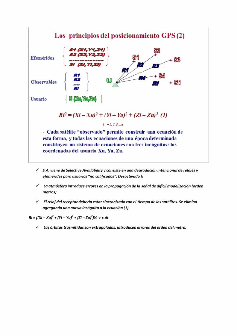
8112019 Tipos de oacuterbitasdocx
httpslidepdfcomreaderfulltipos-de-orbitasdocx 530
bull La SA la degradacioacuten de los relojes satelitales afecta estriacutectamente igual a las dos estaciones
los errores en las efemeacuterides (oacuterbitas) son importantes si la distancia entre las estaciones es
muy grande (maacutes de 50 km) En tal caso se utilizan efemeacuterides precisas
bull La atmoacutesfera introduce errores muy similares para distancias de algunas decenas de km Para
distancias mayores es importante utilizar receptores de doble frecuencia para eliminar los
errores de la ionoacutesfera
bull Es condicioacuten necesaria para alcanzar una solucioacuten apropiada contar con una buena posicioacuten de
partida de lo contrario la precisioacuten de la posicioacuten relativa resultaraacute afectada seguacuten una regla
aproximada
bull Error en la base =gt 1 PPM cada 10 m de error en las coordenadas de partida
bull La atmoacutesfera perturba la propagacioacuten de las sentildeales GPS
bull Los efectos son diferentes en la Ionoacutesfera (capa superior por encima de 80 km) y en la
Tropoacutesfera (capa inferior hasta 11 km)
La ionoacutesfera afecta a las sentildeales en forma inversamente proporcional a la frecuencia de las
mismas Esto permite eliminar su efecto combinando las componentes de las sentildeales GPS en
8112019 Tipos de oacuterbitasdocx
httpslidepdfcomreaderfulltipos-de-orbitasdocx 630
las dos frecuencias posibles L1 y L2 Para ello es necesario utilizar receptores de ldquodoble
frecuenciardquo
La tropoacutesfera (baja atmoacutesfera) introduce errores importantes al producir un retardo en la
sentildeal Se modeliza muy aceptablemente la componente seca y con maacutes incertidumbre la
componente huacutemeda (influencia del vapor de agua en el camino de la onda)
Afecta principalmente la determinacioacuten de alturas con GPS
DOP viene de ldquoDilucioacuten de la Precisionrdquo es decir que es un factor que multiplica a la
precisioacuten de las mediciones desmejorando la precisioacuten real
Oslash Cuanto mayor es el PDOP maacutes desfavorable es la situacioacuten
Oslash Este es un indicador que puede predecirse con una planificacioacuten apropiada
Otros indicadores son HDOP VDOP TDOP
8112019 Tipos de oacuterbitasdocx
httpslidepdfcomreaderfulltipos-de-orbitasdocx 730
8112019 Tipos de oacuterbitasdocx
httpslidepdfcomreaderfulltipos-de-orbitasdocx 830
8112019 Tipos de oacuterbitasdocx
httpslidepdfcomreaderfulltipos-de-orbitasdocx 930
8112019 Tipos de oacuterbitasdocx
httpslidepdfcomreaderfulltipos-de-orbitasdocx 1030
8112019 Tipos de oacuterbitasdocx
httpslidepdfcomreaderfulltipos-de-orbitasdocx 1130
8112019 Tipos de oacuterbitasdocx
httpslidepdfcomreaderfulltipos-de-orbitasdocx 1230
Red Geodeacutesica Nacional Activa- conformada por 15 estaciones establecidas estrateacutegicamente los
cuales registran informaciones las 24 Hrs Del diacutea por los sateacutelites de la constelacioacuten navstar
Red Geodeacutesica Nacional Pasiva- constituida por 55324 veacutertices geodeacutesicos distribuidos en la Repuacuteblica
Mexicana conocido tambieacuten como ldquoEstaciones GPSrdquo y estaacuten materializadas sobre el terreno mediante
una placa que han sido realizados por los levantamientos con el GPS (Sistema de PosicionamientoGlobal) lo cual las dota de valores referenciales al elipsoide en consideracioacuten
8112019 Tipos de oacuterbitasdocx
httpslidepdfcomreaderfulltipos-de-orbitasdocx 1330
8112019 Tipos de oacuterbitasdocx
httpslidepdfcomreaderfulltipos-de-orbitasdocx 1430
DORIS
Introduction
The DORIS (Doppler Orbit determination and Radiopositioning Integrated on Satellite) system for satelliteorbit determination and precise positioning was developed by the Centre National drsquoEtudes Spatiales
( CNES) in conjunction with the Institut Geacuteographique National ( IGN) and the Groupe de Recherche deGeacuteodesie Spatiale ( GRGS)
A proof of concept for the International DORIS Service (IDS) was conducted through a pilot phase prior tothe establishment of the International DORIS Experiment in 1999 by the International Association ofGeodesy (IAG) The IDS formally began on July1 2003 after the IAG official approval at the IUGGGeneral Assembly in Sapporo
The IDS is an IAG Service and operates in close cooperation with the International Earth rotation and
Reference frames Service ( IERS)
The IDS mission
The primary objective of the IDS is to provide a service to support geodetic and geophysical researchactivities through DORIS data and derived products
The IDS collects archives and distributes DORIS observation data sets of sufficient accuracy to satisfythe objectives of a wide range of applications and experimentations From these data sets the followingproducts are derived
Coordinates and velocities of the IDS tracking stations
Geocenter and scale of the Terrestrial Reference Frame
High accuracy ephemerides of the DORIS satellites
Earth orientation parameters (EOPs)
The accuracies of these products are sufficient to support current scientific objectives including
Realization of global accessibility to and the improvement of the International Terrestrial ReferenceFrame ( ITRF)
Monitoring deformations of the solid Earth
Monitoring crustal deformation at tide gauges
Monitoring variations in the hydrosphere (sea level ice-sheets etc)
Orbit determination for scientific satellites
The IDS organization
The IDS accomplishes its mission through the following components
Satellites carrying a DORIS receiver
Network of tracking stations
Data Centers
Analysis centers and Analysis Coordinator
Combination Center
Working Groups
Central Bureau
Governing Board
8112019 Tipos de oacuterbitasdocx
httpslidepdfcomreaderfulltipos-de-orbitasdocx 1530
Satellites carrying a DORIS receiver
Since July 2003 the CNES and the European Space Agency ( ESA) have provided DORIS data to the IDS
Data from additional agencies are expected and welcome DORIS receivers are flown on LEO satellites
for precise orbit determination as well as for geodetic applications Satellites with DORIS receivers are
listed on the IDS website at httpids-dorisorg
A representative of the DORIS system serves as a voting member of the Governing Board
Network of Tracking Stations
The IDS network is composed of DORIS permanent tracking stations located at host institutions and
maintained by the IGN A list of the sites (past and present) is included on the IDS website at httpids-
dorisorg The network also includes additional DORIS stations proposed by the IDS to observe during
specific campaigns of scientific interest
A representative of the Network serves as a voting member of the Governing Board
Data Centers
The Data Centers are in direct contact with the CNES which provides the DORIS data The Data Centers
archive the DORIS data derived products and ancillary information required to process these data
A representative of the Data Centers serves as a voting member of the Governing Board
Analysis Centers and Analysis Coordinator
The Analysis Centers (ACs) are committed to provide at least one of the above IDS products on a regularbasis Expertise in DORIS data analysis and operational capability are essential factors in the selection of Analysis Centers
The Analysis Coordinator assists the Analysis Centers and monitors their activities to ensure that the IDS
objectives are carried out The Analysis Coordinator working with the Analysis Centers is expected toprovide quality control performance evaluation and continued development of appropriate analysisstandards The Analysis Coordinator with the support of the Combination Center is also responsible forthe appropriate combination of the Analysis Centers products into a single set of prescribed data products
The Analysis Coordinator and a representative of the Analysis Centers serve as voting members of the
Governing Board
Combination Center
The IDS appoints a Combination Center ( CC) to combine individual AC solutions and to generate IDS
data products for submission to the IERS for the formulation of the periodic update of the ITRF and
other geodetic products The CC is selected by the Governing Board every four years through a Call forParticipation initiated six months prior to the end of the current CC term Interested centers submit
proposals outlining their plan for operation of the CC and the resources that they will commit
A representative of the Combination Center serves as a voting member of the Governing Board
8112019 Tipos de oacuterbitasdocx
httpslidepdfcomreaderfulltipos-de-orbitasdocx 1630
Working Groups
IDS Working Groups provide expertise on particular topics related to the IDS components and on
development of particular IDS product(s) or service(s) relying on the IDS infrastructure All Working
Groups are created when needed and retired by the IDS Governing Board when their work has been
completed or they are no longer needed Each Working Group must develop a charter that includes a
mandate a list of specific tasks a schedule and an identified Chairperson
The Chairpersons of the Working Groups are non-voting members of the IDS Governing Board (see
below)
Central Bureau
The Central Bureau ( CB) is the executive arm of the IDS Governing Board and as such is responsible forthe general management of the IDS consistent with the directives policies and priorities set by theGoverning Board
In this role the CB within available resources coordinates IDS activities facilitates communicationsmaintains documentation and organizes reports meetings and workshops
The CB responds to external inquiries about the IDS promotes the use of IDS data and products andcoordinates interactions with other services including the IERS
The CB supports the Combination Center in combining the various Analysis Centers products andproviding all information necessary to validate the final combined products
The CB operates the information system for the IDS and produces the IDS Annual Reports and IDS Associates directory
The CB coordinates the publication of other documents required for the satisfactory planning and day-to-day operation of the Service including standards and specifications regarding the performancefunctionality and configuration requirements of all Service elements
Although the Chairperson of the Governing Board is the official representative of the IDS to externalorganizations the CB consistent with the directives established by the Governing Board is responsiblefor the day-to-day liaison with such organizations
The long-term function of the IDS is assured through redundancy and emergency contingency plan for allof its components except for the CB
The Central Bureau serves for a term of four years One year prior to the end of each term the GBformally reviews the performance of the Central Bureau At the behest of the GB the CB may be asked toreconfirm its commitment to serve another four years If the CB agrees it submits a proposal for GBapproval If the CB declines or if the GB chooses to change CB operators the GB announces a Call forProposals for a new IDS Central Bureau to take over responsibilities including a six-month transition
phase with the outgoing Central Bureau
In summary the Central Bureau performs primarily a long-term coordination role to ensure that IDS
participants contribute to the Service in a consistent and harmonious manner and adhere to IDS
standards
The Director of the Central Bureau serves as a voting member of the Governing Board
8112019 Tipos de oacuterbitasdocx
httpslidepdfcomreaderfulltipos-de-orbitasdocx 1730
Governing Board
The principal role of the Governing Board (GB) is to set policy and to exercise broad oversight of all IDS
functions and components It also controls general activities of the Service including restructuring
when appropriate to maintain Service efficiency and reliability
The Governing Board (GB) consists of eleven voting members and a number of non-voting membersThe membership is chosen to try to strike the right balance between project specialists and the generalcommunity The voting membership of the GB is distributed as follows
Elected by IDS Associates (see below)
Analysis Centers representative 1Data centers representative 1 Analysis Coordinator 1Members at large 2
Appointed members
Director of the Central Bureau 1IERS representative to IDS 1IAG representative to IDS 1Combination Center representative 1DORIS System representative (CNES)1Network representative (IGN) 1
Total number of voting members 11
During their mandate the Working Group chairpersons are GB members with voice but without vote
The elected members have staggered four-year terms with elections every two years
There is no limit to the number of terms that a person may serve however he or she may serve only twoterms consecutively as an elected member
The Analysis Centersrsquo representative the Data Centersrsquo representative and one Member -at-Large areelected during the first two-year election
The Analysis Coordinator and the other Member-at-Large are elected in the second two-year election
Although no formula is prescribed efforts should be made to keep the GB membership properly balancedwith regard to supporting organizations and geographic representation
Members of the GB become IAG Fellows with the appropriate rights and privileges as described on the
IAG website after an initial two-year period
GB elections
The GB elects a Chairperson from its members to serve a term of four years with the possibility of re-
election for one additional term The Chairperson does not vote on GB decisions except in the case of a
tie The Chairperson is the official representative of the IDS to external organizations
8112019 Tipos de oacuterbitasdocx
httpslidepdfcomreaderfulltipos-de-orbitasdocx 1830
Five members of the GB are elected by the IDS Associates A nominating committee conducts theelections for membership on the IDS Governing Board
The nominating committee consists of three members The Chair of the nominating committee isappointed by the Chair of the GB and must be a member of the GB not currently up for re-election TheGB chooses the remaining two members of the nominating committee from the list of IDS Associates Thenominating committee solicits nominations from the IDS Associates for each position to be filled at leasttwo candidates are required for each position
The Central Bureau runs the election
All IDS Associates are eligible to vote
Election is by a simple majority of votes received for each position
The two Member-at-Large positions are filled by the two candidates receiving the most votes a vote by
the GB will resolve any situation of a tie
Appointed Members
The IAG and IERS representatives to the IDS Governing Board are appointed respectively by the IAGExecutive Committee and by the IERS Directing Board for a maximum of two four-year terms
The DORIS System representative and the Network representative are appointed by CNES and IGNrespectively for four-year terms without limitation
The Director of the Central Bureau and the Combination Center representative are the two otherappointed members
In case of a resignation from the Governing Board the CB after consulting with the appropriate IDScomponents nominates a replacement candidate for election by the GB The replacement will serve untilthe end of the term of the resigned Board member
GB Decisions
Most decisions at GB meetings are to be made by consensus or by a simple majority vote of the voting
members present provided that there is a quorum consisting of at least six voting members of the GB
GB decisions can be made through email or other correspondence by a majority vote of the GB voting
membership Changes in the IDS Terms of Reference and Chairperson of the GB can only be made by a
23 majority of the members of the GB ie by seven or more votes
GB Meetings
The Board shall meet at least annually and at such other times as shall be considered appropriate by the
Chairperson or at the request of three members
The Central Bureau provides the secretariat of the GBIDS representatives to the IERS and the IAG
Through the existing reciprocity agreement between the IDS and the IERS the IDS Analysis Coordinator
serves as the DORIS Technique Center representative to IERS and as such subject to Governing Board
approval is a member of the IERS Directing Board (together with another person selected by the IDS
Governing Board) This arrangement ensures full cooperation between the two services
The IDS Governing Board will select the IDS representative to the IAG Executive Committee
8112019 Tipos de oacuterbitasdocx
httpslidepdfcomreaderfulltipos-de-orbitasdocx 1930
IDS Associates
IDS Associates are persons representing organizations that participate in any of the IDS components
A participating institution can submit a personrsquos name email and primary IDS function in its organizationto the Central Bureau for application to become an IDS Associate
The Governing Board approves all memberships
The Central Bureau maintains the current list of IDS Associates and makes the list available on the IDSwebsite
IDS Associates vote for the incoming Analysis Centersrsquo representative the Data Centersrsquo representativethe Analysis Coordinator and the Members-at-Large representatives as members of the GB
The GB must approve the list of IDS Associates eligible for voting in the elections at least three monthsprior to the election process
For the purposes of the election current and former GB members are also considered IDS Associates
IDS Associates are considered IAG Affiliates
After a decade of fully operational functioning the DORIS space geodesy system has demonstrated itscapabilities for orbitography and navigation of the satellites and also ground location It plays a key role inthe TopexPoseidon altimetric mission for oceanography providing in association with the Laser techniquea 2 cm accuracy in the radial component of the orbit DORIS and Laser are renewed as the nominalorbitographic system for the Jason mission (end of 2000)
DORIS also provides with Diode navigator on Spot 4 (1993) an orbit in real time within a few meters Itsa world first at this level of precision
Since 1994 and thanks to its more than fifty permanent beacon network DORIS contributes to
the IERS activities for the realization and maintenance of the ITRS (International Terrestrial ReferenceSystem) 3D positions and velocities of the reference sites at a cm and mmyr accuracy lead to scientificstudies (investigations) in the fields of global and regional tectonics Two recent DORIS results appearvery encouraging for the future One concerns a seasonal effect of earth surface fluid mass redistribution(oceanic water atmospheric masses snow ) on the relative positions of the earth mass and earthfigure centers Another concerns vertical displacement of the crust monitored near tides-gages Thisinformation is of major interest for the topic of sea level variations and correlation to the Global Change
Such as the other space geodesy techniques GPS VLBI SLR there is a strong demand among thescientific community to create an International DORIS Service so called IDS TheCSTG commission forinternational co-ordination of space techniques for geodesy of the International Association Geodesy( IAG) and the IERS directing board decided in July 1999 to initiate a DORIS Pilot Experiment Itsobjective was to assess the need and feasibility of an International DORIS Service
Since July1 2003 the International DORIS Service has been officially started as an IAGService after the decision of the IAG Executive Committtee at the IUGG General Assembly in SapporoNew terms of reference were released They describe the goals and organization of the IDS
8112019 Tipos de oacuterbitasdocx
httpslidepdfcomreaderfulltipos-de-orbitasdocx 2030
HOW ALTIMETRY WORKS
Altimetry satellites basically determine the distance from the satellite to a target surface by measuring
the satellite-to-surface round-trip time of a radar pulse However this is not the only measurement
made in the process and a lot of other information can be extracted from altimetry
The magnitude and shape of the echoes (or waveforms) also contain information about the
characteristics of the surface which caused the reflection The best results are obtained over the ocean
which is spatially homogeneous and has a surface which conforms with known statistics Surfaces which
are not homogeneous which contain discontinuities or significant slopes such as some ice rivers or
land surfaces make accurate interpretation more difficult
Basic principle
Radar altimeters permanently transmit signals to Earth and receive the echo from the surface The
satellite orbit have to be accurately tracked (Doris system) and its position is determined relative to an
arbitrary reference surface an ellipsoid The sea surface height (SSH) is the range from the sea surface
to a reference ellipsoid
8112019 Tipos de oacuterbitasdocx
httpslidepdfcomreaderfulltipos-de-orbitasdocx 2130
Pulses and waveforms
Altimetry satellites basically determine the distance from the satellite to a target surface by measuringthe satellite-to-surface round-trip time of a radar pulse The magnitude and shape of the echoes (orwaveforms) also contain information about the characteristics of the surface which caused thereflection
Frequencies used
Several different frequencies are used for radar altimeters Each frequency band has its advantagesand disadvantages sensitivity to atmospheric perturbations for Ku-band better observation of icerain coastal zones land masses for Ka-band
FUTURE TECHNOLOGY IMPROVEMENTS
Satellite altimetry has proven to be a valuable source of data for a broad range of applications Looking beyond the
missions in operational service today future satellites will need to provide better spatial and temporal coverage so
that we can study further near the coasts or mesoscale variations and other phenomena more closely For the
medium term consideration is now being given to altimetry missions capable of scanning the ocean surface to
acquire data at scales of a few tens of kilometres passing over the same spots every few days Other projects onthe drawing board are based on constellations of dedicated low-cost microsatellites The use of opportunity
signals is also being considered with the possibility of retrieving reflected signals transmitted by satellites in the
Global Navigation Satellite System (GNSS)
Altimeter-interferometers
An altimeterinterferometer would include several altimeters mounted on masts which would acquire
measurements simultaneously thus providing continuous single- or multi-altimeter wide-area
coverage ltbrgt Further information
Constellations
One of the ways to improve altimetry resolution is to use several satellites at the same time Until now this has
been done with very different types of satellite The use of several identical satellites in constellation could reduce
costs (development costs and launch costs too for micro-satellites launched by the same rocket)
GNSS altimetry
One approach being pursued to achieve maximum altimetry data coverage is to receive reflected signals
transmitted by satellites in the Global Navigation Satellite System (GNSS) in particular from the Global Positioning
System (GPS) constellation and its European civil counterpart Galileo This concept is based on a satellite in near-
polar orbit (at an altitude of 400 to 500 km) retrieving signals emitted by multiple satellites and reflected by the
ocean surface then analysing these signals to compute sea surface height This concept is currently still only in the
study phase
RADIOMETRY PRINCIPLE
Microwave remote sensing uses passive microwave radiometers The microwaves have wavelength ranging from a
few kHz to THz The ldquopassiverdquo term means that it uses microwaves naturally radiated by the observed area (this is
different from the radar principle where the sensor transmits a microwave signal towards a target and detects the
backscattered radiation)
Radiometry principle
8112019 Tipos de oacuterbitasdocx
httpslidepdfcomreaderfulltipos-de-orbitasdocx 2230
Radiometry principle
Satellite passive microwave radiometers measure raw antenna counts from which we determine the antenna
temperature and then calculate the brightness temperature of the Earth Large antennas are used for the various
channels of the radiometer and in operation each antenna feedhorn passes a hot and cold target in order toprovide consistently calibrated raw counts Brightness temperature is a measure of the radiance of microwave
radiation traveling upward from the top of Earths atmosphere The conversion from radiometer counts to top-of-
the-atmosphere (TOA) brightness temperature is called the calibration process Several calibration processing
steps are required to derive the brightness temperature values
Radiometry applications
Microwave radiometer brightness temperatures are considered as a fundamental climate data record
and are the values from which we derive ocean measurements of wind speed water vapor cloud liquid
water rain rate and sea surface temperature
Missions
The main passive microwave radiometers are listed below (instrumentsatellite)
AMSR-E on Aqua
SSMI on DMSP F08 F10 F11 F13 F14 F15
SSMIS on DMSP F16 F17
WindSat on Coriolis
TMI on TRMM
AMSR2 GCOM - W1
Radiometers and altimeters
In the altimetry domain interesting radiometers are those that are on-board altimetric missions such
as JMR MWR AMR Altika radiometer etc These microwave radiometers measure the total water
vapor along the path viewed by the altimeter In addition to measuring total water vapor they are used
for range correction and to measure brightness temperatures
8112019 Tipos de oacuterbitasdocx
httpslidepdfcomreaderfulltipos-de-orbitasdocx 2330
Using generally two (238 37 GHz for Altika radiometer on board SARAL) or three different frequencies
(eg 187 238 340GHz for the AMR on-board OSTMJason-2) measurements acquired at each
frequency are combined to determine atmospheric water vapor and liquid water content Once the
water content is known it is possible to determine the correction to be applied for radar signal path
delays
Altimetry missions that operate without radiometer (eg Cryosat-2) can use estimation of wet
tropospheric correction coming from atmospheric models
For more information
JMR instrument on-board Jason-1
AMR instrument on-board OSTMJason-2
MWR instrument on-board Envisat
AltiKa on-board SARAL
The International Laser Ranging Service (ILRS) provides global satellite and lunar laser ranging data and their related
products to support geodetic and geophysical research activities as well as IERS products important to the
maintenance of an accurate International Terrestrial Reference Frame (ITRF) The service develops the necessary
global standardsspecifications and encourages international adherence to its conventions The ILRS is one of the
space geodetic services of the International Association of Geodesy (IAG)
The ILRS collects merges archives and distributes Satellite Laser Ranging (SLR) and Lunar Laser Ranging (LLR)
observation data sets of sufficient accuracy to satisfy the objectives of a wide range of scientific engineering and
operational applications and experimentation These data sets are used by the ILRS to generate a number of
scientific and operational data products including
Earth orientation parameters (polar motion and length of day)
Station coordinates and velocities of the ILRS tracking systems
Time-varying geocenter coordinates
Static and time-varying coefficients of the Earths gravity field
Centimeter accuracy satellite ephemerides
Fundamental physical constants
Lunar ephemerides and librations
Lunar orientation parameters
The accuracy of SLRLLR data products is sufficient to support a variety of scientific and operational applications
including
Realization of global accessibility to and the improvement of the International Terrestrial Reference Frame
(ITRF)
Monitoring three dimensional deformations of the solid Earth
Monitoring Earth rotation and polar motion
8112019 Tipos de oacuterbitasdocx
httpslidepdfcomreaderfulltipos-de-orbitasdocx 2430
Support the monitoring of variations in the topography and volume of the liquid Earth (ocean circulation mean
sea level ice sheet thickness wave heights etc)
Tidally generated variations in atmospheric mass distribution
Calibration of microwave tracking techniques
Picosecond global time transfer experiments
Astrometric observations including determination of the dynamic equinox obliquity of the ecliptic and the
precession constant
Gravitational and general relativistic studies including Einsteins Equivalence Principle the Robertson-Walker b
parameter and time rate of change of the gravitational constant
Lunar physics including the dissipation of rotational energy shape of the core-mantle boundary (Love Number
k2) and free librations and stimulating mechanisms
Solar System ties to the International Celestial Reference Frame (ICRF)
Satellite Laser Ranging (SLR) and Lunar Laser Ranging (LLR) use short-pulse lasers and state-of-the-art opticalreceivers and timing electronics to measure the two-way time of flight (and hence distance) from ground stations toretroreflector arrays on Earth orbiting satellites and the Moon Scientific products derived using SLR and LLR datainclude precise geocentric positions and motions of ground stations satellite orbits components of Earthrsquos gravityfield and their temporal variations Earth Orientation Parameters (EOP) precise lunar ephemerides and informationabout the internal structure of the Moon Laser ranging systems are already measuring the one-way distance toremote optical receivers in space and can perform very accurate time transfer between sites far apart Laser rangingactivities are organized under the International Laser Ranging Service (ILRS) which provides global satellite andlunar laser ranging data and their derived data products to support research in geodesy geophysics Lunar scienceand fundamental constants This includes data products that are fundamental to the International TerrestrialReference Frame (ITRF) which is established and maintained by the International Earth Rotation and ReferenceSystems Service (IERS) The ILRS develops the necessary global standardsspecifications for laser ranging activitiesand encourages international adherence to its conventions
Analysis Products
The ILRS provides a service to utilize Satellite and Lunar Laser Ranging data to generate geodetic geodynamic andgeophysical scientific products
Currently five SLR analysis groups (ASI DGFI GFZ JCET and NSGF) provide direct input for the official ILRSproducts (stationcoordinates and Earth Orientation Parameters EOPs) The results of the ILRS POS+EOP pilot project wereevaluated during the AWG meeting in San Fernando The five contributors were acknowledged and given an officialstatus In addition ASI was selected as the official ILRS primary combination center and DGFI was selected as theofficial ILRS backup combination center each for a two-year term As well as the contributors of individual solutionsthese combination centers must follow strict timelines and provide routine products of the highest possible qualityWeekly official ILRS products from these two combination centers are now available in SINEX format eachWednesday at CDDIS and EDC Analysis centers will again compete for the ILRS combination and backup center in
mid-2006 at the International Laser Ranging Workshop in Australia All groups are encouraged to develop (thequality of) their contributions furtherThe ILRS now generates weekly unconstrained solutions for station coordinates (valid for the mid-point of each 7-day interval) and EOPs (x-pole y-pole and Length-Of-Day (LOD) all of them for 1-day intervals) These results arestored in subdirectories of the form pos+eopYYMMDD where YYMMDD is the date (YY =2 digit year MM =2 digitmonth and DD=2 digit day) of the end of each 7-day interval Within each subdirectory one finds so-called individualsolutions and combination solutions that are explained belowFor the individual contributions to the POS+EOPproject filenames are of the form (examples reflect CDDIS archive)ftpcddisgsfcnasagovpubslrproductspos+eopYYMMDDCENTER pos+eopYYMMDDv1snxZHere CENTER is replaced by the name of the actual contributor It is the first solution that is generated for thisperiod and by this analysis center hence v1 If re-computations are necessary the version number will be
8112019 Tipos de oacuterbitasdocx
httpslidepdfcomreaderfulltipos-de-orbitasdocx 2530
increased by one solutions for new weeks will start with v1 however The results are stored in the SINEX format(snx) The reader is refered to the COMMENTS section of each solution (in the file itself) or more generalexplanations of SINEX for further details of the solution andor the formatThe official ILRS primary product on POS+EOP is labeled as
ftpcddisgsfcnasagovpubslrproductspos+eopYYMMDDilrsapos+eopYYMMDDv1snxZIn a similar fashion the EOP solutions (wrt ITRF2000) generated by the official ILRS primary combination centerare named
ftpcddisgsfcnasagovpubslrproductspos+eopYYMMDDilrsaeopYYMMDDv1snxZThe ILRS also has an official backup combination center and its products are labeled
ftpcddisgsfcnasagovpubslrproductspos+eopYYMMDDilrsbpos+eopYYMMDDv1snxZftpcddisgsfcnasagovpubslrproductspos+eopYYMMDDilrsbeopYYMMDDv1snxZCurrently the ILRS AWG is in the process of computing similar solutions for the years before the workshop in SanFernando At this moment the AWG works on solutions going back to the launch date of LAGEOS-2 (ie November1992) It is foreseen that this will (at a later stage) be followed by computations for the time frame extending back toSeptember 1983 the beginning of the MERIT campaign
Historical products include
Earth Orientation Parameters (EOP)o GSFC 98L01 solution
o CSR 95L01 solutiono Delft University of Technology 92L01 solutiono GeoForschungsZentrum 95L01 solutiono Centro di Geodesia Spaziale solutions
Coordinates and velocities of the tracking stations
Geocenter coordinates - IERS Geocenter campaign results IERS TN25
In Satellite Laser Ranging a short pulse of coherent light generated by a laser (Light Amplification by Stimulated
Emission of Radiation) is transmitted in a narrow beam to illuminate corner cube retroreflectors on the satellite Thereturn signal typically a few photons is collected by a telescope and the time-of-flight is measured Using informationabout the satellitersquos orbit the time-of-flight and the speed of light the location of the ranging station can bedetermined Similar data acquired by another station many kilometers distant from the first or on a different continentcan be used to determine the distance between stations to precisions of centimeters or better Repetitivemeasurements over months and years yield the changein distance or the motion of the Earthrsquos crust
Laser ranging to a near-Earth satellite was initiated byNASA in 1964 with the launch of the Beacon-B satelliteSince that time ranging precision spurred by scientificrequirements has improved by a factor of a thousandfrom a few meters to a few millimeters Similarly thenetwork of laser stations has grown from a fewexperimental sites to a global network of 43 stations inmore than 30 countries Most of these stations (33) arefunded by organizations other than NASA
During the past three decades the global Satellite LaserRanging (SLR) network has evolved into a powerfulsource of data for studies of the solid Earth and itsocean and atmospheric systems including
Detection and monitoring of tectonic plate motioncrustal deformation Earth rotation and polar motion
Modeling of the spatial and temporal variations of the Earthrsquos gravitational field
Determination of basin-scale ocean tides
Monitoring of millimeter-level variations in the location of the center of mass of the total Earth system (solidEarth-atmosphere-oceans)
Establishment and maintenance of the International Terrestrial Reference System (ITRS) and
Detection and monitoring of post-glacial rebound and subsidence
8112019 Tipos de oacuterbitasdocx
httpslidepdfcomreaderfulltipos-de-orbitasdocx 2630
In addition SLR provides precise orbit determination for spaceborne radar altimeter missions mapping the oceansurface (which are used to model global ocean circulation) for mapping volumetric changes in continental ice massesand for land topography It provides a means for subnanosecond global time transfer and a basis for special tests ofthe Theory of General Relativity
SLR uses special passive spacecraft in very stable orbits A low area to mass ratio minimizes the effects ofatmospheric drag and solar radiation pressure on the satellitersquos orbit
An example of such a satellite is the Laser Geodynamics Satellite (LAGEOS-1) which was launched by the UnitedStates in 1976 into a 6000 kilometer circular orbit with a near polar inclination Lageos-I and its sister satelliteLageos-II (built by the Agenzia Spaziale Italiana of Italy and launched in 1992 into a 6000 kilometer orbit but with aninclination of 51 degrees) have a 60 centimeter spherical shape and weigh 411 kilograms The exterior surface ofboth satellites is covered by 426 retroreflectors
Other satellites for SLR include Starlette (1000 km) and Stella (800 km) developed and launched by France Etalon-Iand -2 (19000 km) developed and launched by the former USSR and Ajisai (1500 km) developed and launched byJapan To obtain data for precise orbit determination retroreflectors are also mounted on the USFranceTopexPoseidon spacecraft the European Space Agency Earth Remote Sensing satellites (ERS-1 and 2) and on afew of the United States Global Positioning System (GPS) satellites
Fixed and mobile SLR systems have been used to acquire data for studies of crustal deformation and plate motion atscales from several hundred kilometers to several thousand kilometers to monitor polar motion and Earth rotationand to model the Earthrsquos gravity field
Lunar Laser Ranging (LLR)
During three US American Apollo missions (11 14 and 15) and two unmanned Soviet missions (Luna 17 and Luna21) retro-reflectors were deployed near the lunar landing sites between 1969 and 1973 The Lunar Laser Ranging(LLR) experiment has continuously provided range data for about 41 years generating about 17000 normal pointsThe main benefit of this space geodetic technique is the determination of a host of parameters describing lunarephemeris lunar physics the Moons interior various reference frames Earth orientation parameters and the Earth-Moon dynamics LLR has also become one of the strongest tools for testing Einsteins theory of general relativity inthe solar system no violations of general relativity have been found so far However the basis for all scientificanalyses is more high quality data from a well-distributed global LLR network More information is provided onthe LLR page
SLR and LLR are used in the following scientific research
Atmosphere-Hydrosphere-Cryosphere-Solid Earth Interactions Long-Term Dynamics of the Solid Earth Oceans and Ice Fields
Tides
Sensing of surface elevations
Mantle
Lunar Science
About IVS
Overview of IVS
IVS is an international collaboration of organizations which operate or support Very Long Baseline Interferometry(VLB I) components
The objectives of IVS are
to provide a service to support geodetic geophysical and astrometric research and operational activities
to promote research and development activities in all aspects of the geodetic and astrometric VLBI technique and
to interact with the community of users of VLBI products and to integrate VLBI into a global Earth observing system
The service aspect of IVS is meant to serve both outside users and the geodetic and astrometric community itselfBoth the contributors and users of data will be served
8112019 Tipos de oacuterbitasdocx
httpslidepdfcomreaderfulltipos-de-orbitasdocx 2730
IVS provides data and products for the scientific community Some of the products are
a terrestrial reference frame (TRF)
the international celestial reference frame (ICRF) and
Earth orientation parameters (EOP)
All IVS data and products are archived in data centers and are publically available for research in relatedareas of geodesy geophysics and astrometry
General The IVS observing program consists of various series of 24-hour observing sessions The
program is planned by the Observing Program Committee coordinated by the IVS Coordinating Center and
executed by the Network Stations Operation Centers andCorrelators The result of the observing program is
the data held in the Data Centers that is then available for analysis The flow of data and the resulting
products are shown graphically on the IVS structure and flow diagram Auxiliary data files such as schedule
and notes files are used to facilitate the observing operations They can be accessed from the IVS
Datapage or following procedures outlined in the Download Schedules page
IVS Live Following the success of the dynamic Web site for the IYA09 session Laboratoire
dAstrophysique de Bordeaux developed a generalized version of this tool for the entire IVS observingplan The resulting IVS Live site allows the user to monitor each session in real-time in terms of stations
scans and sources being used It provides links to Webcams and further ancillary information Follow
the countdown to the next IVS session or check out past or future IVS sessions using the session
calendar Many thanks to Arnaud Collioud and Bordeaux Observatory for making this possible
IVS Network Stations acquire geodetic and astrometric VLBI data Data acquisition at Network Stations is
controlled by schedules prepared by Operation Centers The raw data and log files are transmitted to
the Correlators for processing Details of the planned sessions are published in the Master Files maintained
by the Coordinating Center
About the IGS
The IGS global system of satellite tracking stations Data Centers and Analysis
Centers puts high-quality GPS data and data products on line in near real time to
meet the objectives of a wide range of scientific and engineering applications and
studies
The IGS collects archives and distributes GPS observation data sets of sufficientaccuracy to satisfy the objectives of a wide range of applications and experimentationThese data sets are used by the IGS to generate the data products mentioned abovewhich are made available to interested users through the Internet In particular theaccuracies of IGS products are sufficient for the improvement and extension of theInternational Terrestrial Reference Frame (ITRF) the monitoring of solid Earthdeformations the monitoring of Earth rotation and variations in the liquid Earth (sealevel ice-sheets etc) for scientific satellite orbit determinations ionospheremonitoring and recovery of precipitable water vapor measurements
8112019 Tipos de oacuterbitasdocx
httpslidepdfcomreaderfulltipos-de-orbitasdocx 2830
Mission
The primary mission of the International GPS Service as stated in the organizations
2002-2007 Strategic Plan is
The International GPS Service is committed to providing the highest quality data
and products as the standard for global navigation satellite systems (GNSS) in
support of Earth science research multidisciplinary applications and education
These activities aim to advance scientific understanding of the Earth system
components and their interactions as well as to facilitate other applications
benefiting society
The IGS Terms of Reference (comparable to the by-laws of the organization)describes in broad terms the goals and organization of the IGS
To accomplish its mission the IGS has a number of components an internationalnetwork of over 350 continuously operating dual-frequency GPS stations more than adozen regional and operational data centers three global data centers seven analysiscenters and a number of associate or regional analysis centers The Central Bureau forthe service is located at the Jet Propulsion Laboratory which maintains the CentralBureau Information System (CBIS) and ensures access to IGS products andinformation An international Governing Board oversees all aspects of the IGS TheIGS is an approved service of the International Association of Geodesy since 1994and is recognized as a member of the Federation of Astronomical and Geophysical
Data Analysis Services (FAGS) since 1996
For more information concerning IGS organization click here
History
Since the late 1980s the US Global Positioning System (GPS) constellation ofsatellites has come to play a major role in regional and global studies of Earth In theface of continued growth and diversification of GPS applications the worldwidescientific community has made an effort to promote international standards for GPS
data acquisition and analysis and to deploy and operate a common comprehensiveglobal tracking system
As part of this effort the IGS was formally recognized in 1993 by the InternationalAssociation of Geodesy (IAG) and began routine operations on January 1 1994 providing GPS orbits tracking data and other data products in support of geodeticand geophysical research In particular since January 1994 the IGS has madeavailable to its user community the IGS official orbit based on contributions from the
8112019 Tipos de oacuterbitasdocx
httpslidepdfcomreaderfulltipos-de-orbitasdocx 2930
seven current IGS Analysis Centers The IGS also supports a variety of governmentaland commercial activities and develops international GPS data standards andspecifications A description of the development and evolution of the IGS can befound in a number of publications with detailed documentation contained in the IGSAnnual Report Series published by the IGS Central Bureau via the World Wide WebThis series contains the yearly contributions from all components of service anddemonstrates that the key to success of the IGS has been the broad support of theinternational geodynamics and geodetic communities and their sponsoringorganizations This Information System is sponsored by the National Aeronautic andSpace Administration ( NASA) and managed for NASA by the Jet PropulsionLaboratory (JPL) of the California Institute of Technology (Caltech)
Operations
The IGS has developed a worldwide system comprising satellite tracking stations
Data Centers and Analysis Centers to put high-quality GPS data and data productson line within a day of observations For example following the NorthridgeCalifornia earthquake in January 1994 analysis teams using IGS-supplied data and products were able to quickly evaluate the disasters immediate effects by determiningstation displacements accurately to within a few millimeters
The IGS global network of permanent tracking stations each equipped with a GPSreceiver generates raw orbit and tracking data The Operational Data Centers whichare in direct contact with the tracking sites collect the raw receiver data and formatthem according to a common standard using a data format called Receiver
Independent Exchange (RINEX) The formatted data are then forwarded to theRegional or Global Data Centers To reduce electronic network traffic the RegionalData Centers are used to collect data from several Operational Data Centers beforetransmitting them to the Global Data Centers Data not used for global analyses arearchived and available for online access at the Regional Data Centers The GlobalData Centers archive and provide on-line access to tracking data and data products
Products and Applications
The IGS collects archives and distributes GPS observation data sets of sufficient
accuracy to meet the objectives of a wide range of scientific and engineeringapplications and studies These data sets are used to generate the following products
GPS satellite ephemerides
GLONASS satellite ephemerides
Earth rotation parameters
IGS tracking station coordinates and velocities
8112019 Tipos de oacuterbitasdocx
httpslidepdfcomreaderfulltipos-de-orbitasdocx 3030
GPS satellite and IGS tracking station clock information
Zenith tropospheric path delay estimates
Global ionospheric maps
IGS products support scientific activities such as improving and extending theInternational Earth Rotation Service (IERS) Terrestrial Reference Frame (ITRF)monitoring deformations of the solid Earth and variations in the liquid Earth (sea levelice sheets etc) and in Earth rotation determining orbits of scientific satellites andmonitoring the ionosphere For example geodynamics investigators who use GPS inlocal regions can include data from one or more nearby IGS stations fix the sitecoordinates from such stations to their ITRF values and more importantly use the precise IGS orbits without further refinement Data from an investigators localnetwork can then be analyzed with maximum accuracy and minimum computational burden Furthermore the results will be in a well-defined global reference frame
An additional aspect of IGS products is for the densification of the ITRF at a moreregional level This is accomplished through the rigorous combination of regional orlocal network solutions utilizing the Solution Independent Exchange Format (SINEX) and a process defined in the densification section
In the future the IGS infrastructure could become a valuable asset for support of newground-based applications and could also contribute to space-based missions inwhich highly accurate flight and ground differential techniques are required
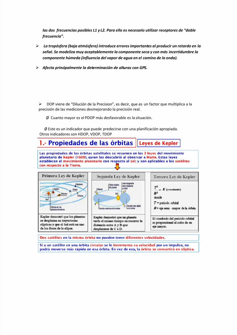
8112019 Tipos de oacuterbitasdocx
httpslidepdfcomreaderfulltipos-de-orbitasdocx 630
las dos frecuencias posibles L1 y L2 Para ello es necesario utilizar receptores de ldquodoble
frecuenciardquo
La tropoacutesfera (baja atmoacutesfera) introduce errores importantes al producir un retardo en la
sentildeal Se modeliza muy aceptablemente la componente seca y con maacutes incertidumbre la
componente huacutemeda (influencia del vapor de agua en el camino de la onda)
Afecta principalmente la determinacioacuten de alturas con GPS
DOP viene de ldquoDilucioacuten de la Precisionrdquo es decir que es un factor que multiplica a la
precisioacuten de las mediciones desmejorando la precisioacuten real
Oslash Cuanto mayor es el PDOP maacutes desfavorable es la situacioacuten
Oslash Este es un indicador que puede predecirse con una planificacioacuten apropiada
Otros indicadores son HDOP VDOP TDOP
8112019 Tipos de oacuterbitasdocx
httpslidepdfcomreaderfulltipos-de-orbitasdocx 730
8112019 Tipos de oacuterbitasdocx
httpslidepdfcomreaderfulltipos-de-orbitasdocx 830
8112019 Tipos de oacuterbitasdocx
httpslidepdfcomreaderfulltipos-de-orbitasdocx 930
8112019 Tipos de oacuterbitasdocx
httpslidepdfcomreaderfulltipos-de-orbitasdocx 1030
8112019 Tipos de oacuterbitasdocx
httpslidepdfcomreaderfulltipos-de-orbitasdocx 1130
8112019 Tipos de oacuterbitasdocx
httpslidepdfcomreaderfulltipos-de-orbitasdocx 1230
Red Geodeacutesica Nacional Activa- conformada por 15 estaciones establecidas estrateacutegicamente los
cuales registran informaciones las 24 Hrs Del diacutea por los sateacutelites de la constelacioacuten navstar
Red Geodeacutesica Nacional Pasiva- constituida por 55324 veacutertices geodeacutesicos distribuidos en la Repuacuteblica
Mexicana conocido tambieacuten como ldquoEstaciones GPSrdquo y estaacuten materializadas sobre el terreno mediante
una placa que han sido realizados por los levantamientos con el GPS (Sistema de PosicionamientoGlobal) lo cual las dota de valores referenciales al elipsoide en consideracioacuten
8112019 Tipos de oacuterbitasdocx
httpslidepdfcomreaderfulltipos-de-orbitasdocx 1330
8112019 Tipos de oacuterbitasdocx
httpslidepdfcomreaderfulltipos-de-orbitasdocx 1430
DORIS
Introduction
The DORIS (Doppler Orbit determination and Radiopositioning Integrated on Satellite) system for satelliteorbit determination and precise positioning was developed by the Centre National drsquoEtudes Spatiales
( CNES) in conjunction with the Institut Geacuteographique National ( IGN) and the Groupe de Recherche deGeacuteodesie Spatiale ( GRGS)
A proof of concept for the International DORIS Service (IDS) was conducted through a pilot phase prior tothe establishment of the International DORIS Experiment in 1999 by the International Association ofGeodesy (IAG) The IDS formally began on July1 2003 after the IAG official approval at the IUGGGeneral Assembly in Sapporo
The IDS is an IAG Service and operates in close cooperation with the International Earth rotation and
Reference frames Service ( IERS)
The IDS mission
The primary objective of the IDS is to provide a service to support geodetic and geophysical researchactivities through DORIS data and derived products
The IDS collects archives and distributes DORIS observation data sets of sufficient accuracy to satisfythe objectives of a wide range of applications and experimentations From these data sets the followingproducts are derived
Coordinates and velocities of the IDS tracking stations
Geocenter and scale of the Terrestrial Reference Frame
High accuracy ephemerides of the DORIS satellites
Earth orientation parameters (EOPs)
The accuracies of these products are sufficient to support current scientific objectives including
Realization of global accessibility to and the improvement of the International Terrestrial ReferenceFrame ( ITRF)
Monitoring deformations of the solid Earth
Monitoring crustal deformation at tide gauges
Monitoring variations in the hydrosphere (sea level ice-sheets etc)
Orbit determination for scientific satellites
The IDS organization
The IDS accomplishes its mission through the following components
Satellites carrying a DORIS receiver
Network of tracking stations
Data Centers
Analysis centers and Analysis Coordinator
Combination Center
Working Groups
Central Bureau
Governing Board
8112019 Tipos de oacuterbitasdocx
httpslidepdfcomreaderfulltipos-de-orbitasdocx 1530
Satellites carrying a DORIS receiver
Since July 2003 the CNES and the European Space Agency ( ESA) have provided DORIS data to the IDS
Data from additional agencies are expected and welcome DORIS receivers are flown on LEO satellites
for precise orbit determination as well as for geodetic applications Satellites with DORIS receivers are
listed on the IDS website at httpids-dorisorg
A representative of the DORIS system serves as a voting member of the Governing Board
Network of Tracking Stations
The IDS network is composed of DORIS permanent tracking stations located at host institutions and
maintained by the IGN A list of the sites (past and present) is included on the IDS website at httpids-
dorisorg The network also includes additional DORIS stations proposed by the IDS to observe during
specific campaigns of scientific interest
A representative of the Network serves as a voting member of the Governing Board
Data Centers
The Data Centers are in direct contact with the CNES which provides the DORIS data The Data Centers
archive the DORIS data derived products and ancillary information required to process these data
A representative of the Data Centers serves as a voting member of the Governing Board
Analysis Centers and Analysis Coordinator
The Analysis Centers (ACs) are committed to provide at least one of the above IDS products on a regularbasis Expertise in DORIS data analysis and operational capability are essential factors in the selection of Analysis Centers
The Analysis Coordinator assists the Analysis Centers and monitors their activities to ensure that the IDS
objectives are carried out The Analysis Coordinator working with the Analysis Centers is expected toprovide quality control performance evaluation and continued development of appropriate analysisstandards The Analysis Coordinator with the support of the Combination Center is also responsible forthe appropriate combination of the Analysis Centers products into a single set of prescribed data products
The Analysis Coordinator and a representative of the Analysis Centers serve as voting members of the
Governing Board
Combination Center
The IDS appoints a Combination Center ( CC) to combine individual AC solutions and to generate IDS
data products for submission to the IERS for the formulation of the periodic update of the ITRF and
other geodetic products The CC is selected by the Governing Board every four years through a Call forParticipation initiated six months prior to the end of the current CC term Interested centers submit
proposals outlining their plan for operation of the CC and the resources that they will commit
A representative of the Combination Center serves as a voting member of the Governing Board
8112019 Tipos de oacuterbitasdocx
httpslidepdfcomreaderfulltipos-de-orbitasdocx 1630
Working Groups
IDS Working Groups provide expertise on particular topics related to the IDS components and on
development of particular IDS product(s) or service(s) relying on the IDS infrastructure All Working
Groups are created when needed and retired by the IDS Governing Board when their work has been
completed or they are no longer needed Each Working Group must develop a charter that includes a
mandate a list of specific tasks a schedule and an identified Chairperson
The Chairpersons of the Working Groups are non-voting members of the IDS Governing Board (see
below)
Central Bureau
The Central Bureau ( CB) is the executive arm of the IDS Governing Board and as such is responsible forthe general management of the IDS consistent with the directives policies and priorities set by theGoverning Board
In this role the CB within available resources coordinates IDS activities facilitates communicationsmaintains documentation and organizes reports meetings and workshops
The CB responds to external inquiries about the IDS promotes the use of IDS data and products andcoordinates interactions with other services including the IERS
The CB supports the Combination Center in combining the various Analysis Centers products andproviding all information necessary to validate the final combined products
The CB operates the information system for the IDS and produces the IDS Annual Reports and IDS Associates directory
The CB coordinates the publication of other documents required for the satisfactory planning and day-to-day operation of the Service including standards and specifications regarding the performancefunctionality and configuration requirements of all Service elements
Although the Chairperson of the Governing Board is the official representative of the IDS to externalorganizations the CB consistent with the directives established by the Governing Board is responsiblefor the day-to-day liaison with such organizations
The long-term function of the IDS is assured through redundancy and emergency contingency plan for allof its components except for the CB
The Central Bureau serves for a term of four years One year prior to the end of each term the GBformally reviews the performance of the Central Bureau At the behest of the GB the CB may be asked toreconfirm its commitment to serve another four years If the CB agrees it submits a proposal for GBapproval If the CB declines or if the GB chooses to change CB operators the GB announces a Call forProposals for a new IDS Central Bureau to take over responsibilities including a six-month transition
phase with the outgoing Central Bureau
In summary the Central Bureau performs primarily a long-term coordination role to ensure that IDS
participants contribute to the Service in a consistent and harmonious manner and adhere to IDS
standards
The Director of the Central Bureau serves as a voting member of the Governing Board
8112019 Tipos de oacuterbitasdocx
httpslidepdfcomreaderfulltipos-de-orbitasdocx 1730
Governing Board
The principal role of the Governing Board (GB) is to set policy and to exercise broad oversight of all IDS
functions and components It also controls general activities of the Service including restructuring
when appropriate to maintain Service efficiency and reliability
The Governing Board (GB) consists of eleven voting members and a number of non-voting membersThe membership is chosen to try to strike the right balance between project specialists and the generalcommunity The voting membership of the GB is distributed as follows
Elected by IDS Associates (see below)
Analysis Centers representative 1Data centers representative 1 Analysis Coordinator 1Members at large 2
Appointed members
Director of the Central Bureau 1IERS representative to IDS 1IAG representative to IDS 1Combination Center representative 1DORIS System representative (CNES)1Network representative (IGN) 1
Total number of voting members 11
During their mandate the Working Group chairpersons are GB members with voice but without vote
The elected members have staggered four-year terms with elections every two years
There is no limit to the number of terms that a person may serve however he or she may serve only twoterms consecutively as an elected member
The Analysis Centersrsquo representative the Data Centersrsquo representative and one Member -at-Large areelected during the first two-year election
The Analysis Coordinator and the other Member-at-Large are elected in the second two-year election
Although no formula is prescribed efforts should be made to keep the GB membership properly balancedwith regard to supporting organizations and geographic representation
Members of the GB become IAG Fellows with the appropriate rights and privileges as described on the
IAG website after an initial two-year period
GB elections
The GB elects a Chairperson from its members to serve a term of four years with the possibility of re-
election for one additional term The Chairperson does not vote on GB decisions except in the case of a
tie The Chairperson is the official representative of the IDS to external organizations
8112019 Tipos de oacuterbitasdocx
httpslidepdfcomreaderfulltipos-de-orbitasdocx 1830
Five members of the GB are elected by the IDS Associates A nominating committee conducts theelections for membership on the IDS Governing Board
The nominating committee consists of three members The Chair of the nominating committee isappointed by the Chair of the GB and must be a member of the GB not currently up for re-election TheGB chooses the remaining two members of the nominating committee from the list of IDS Associates Thenominating committee solicits nominations from the IDS Associates for each position to be filled at leasttwo candidates are required for each position
The Central Bureau runs the election
All IDS Associates are eligible to vote
Election is by a simple majority of votes received for each position
The two Member-at-Large positions are filled by the two candidates receiving the most votes a vote by
the GB will resolve any situation of a tie
Appointed Members
The IAG and IERS representatives to the IDS Governing Board are appointed respectively by the IAGExecutive Committee and by the IERS Directing Board for a maximum of two four-year terms
The DORIS System representative and the Network representative are appointed by CNES and IGNrespectively for four-year terms without limitation
The Director of the Central Bureau and the Combination Center representative are the two otherappointed members
In case of a resignation from the Governing Board the CB after consulting with the appropriate IDScomponents nominates a replacement candidate for election by the GB The replacement will serve untilthe end of the term of the resigned Board member
GB Decisions
Most decisions at GB meetings are to be made by consensus or by a simple majority vote of the voting
members present provided that there is a quorum consisting of at least six voting members of the GB
GB decisions can be made through email or other correspondence by a majority vote of the GB voting
membership Changes in the IDS Terms of Reference and Chairperson of the GB can only be made by a
23 majority of the members of the GB ie by seven or more votes
GB Meetings
The Board shall meet at least annually and at such other times as shall be considered appropriate by the
Chairperson or at the request of three members
The Central Bureau provides the secretariat of the GBIDS representatives to the IERS and the IAG
Through the existing reciprocity agreement between the IDS and the IERS the IDS Analysis Coordinator
serves as the DORIS Technique Center representative to IERS and as such subject to Governing Board
approval is a member of the IERS Directing Board (together with another person selected by the IDS
Governing Board) This arrangement ensures full cooperation between the two services
The IDS Governing Board will select the IDS representative to the IAG Executive Committee
8112019 Tipos de oacuterbitasdocx
httpslidepdfcomreaderfulltipos-de-orbitasdocx 1930
IDS Associates
IDS Associates are persons representing organizations that participate in any of the IDS components
A participating institution can submit a personrsquos name email and primary IDS function in its organizationto the Central Bureau for application to become an IDS Associate
The Governing Board approves all memberships
The Central Bureau maintains the current list of IDS Associates and makes the list available on the IDSwebsite
IDS Associates vote for the incoming Analysis Centersrsquo representative the Data Centersrsquo representativethe Analysis Coordinator and the Members-at-Large representatives as members of the GB
The GB must approve the list of IDS Associates eligible for voting in the elections at least three monthsprior to the election process
For the purposes of the election current and former GB members are also considered IDS Associates
IDS Associates are considered IAG Affiliates
After a decade of fully operational functioning the DORIS space geodesy system has demonstrated itscapabilities for orbitography and navigation of the satellites and also ground location It plays a key role inthe TopexPoseidon altimetric mission for oceanography providing in association with the Laser techniquea 2 cm accuracy in the radial component of the orbit DORIS and Laser are renewed as the nominalorbitographic system for the Jason mission (end of 2000)
DORIS also provides with Diode navigator on Spot 4 (1993) an orbit in real time within a few meters Itsa world first at this level of precision
Since 1994 and thanks to its more than fifty permanent beacon network DORIS contributes to
the IERS activities for the realization and maintenance of the ITRS (International Terrestrial ReferenceSystem) 3D positions and velocities of the reference sites at a cm and mmyr accuracy lead to scientificstudies (investigations) in the fields of global and regional tectonics Two recent DORIS results appearvery encouraging for the future One concerns a seasonal effect of earth surface fluid mass redistribution(oceanic water atmospheric masses snow ) on the relative positions of the earth mass and earthfigure centers Another concerns vertical displacement of the crust monitored near tides-gages Thisinformation is of major interest for the topic of sea level variations and correlation to the Global Change
Such as the other space geodesy techniques GPS VLBI SLR there is a strong demand among thescientific community to create an International DORIS Service so called IDS TheCSTG commission forinternational co-ordination of space techniques for geodesy of the International Association Geodesy( IAG) and the IERS directing board decided in July 1999 to initiate a DORIS Pilot Experiment Itsobjective was to assess the need and feasibility of an International DORIS Service
Since July1 2003 the International DORIS Service has been officially started as an IAGService after the decision of the IAG Executive Committtee at the IUGG General Assembly in SapporoNew terms of reference were released They describe the goals and organization of the IDS
8112019 Tipos de oacuterbitasdocx
httpslidepdfcomreaderfulltipos-de-orbitasdocx 2030
HOW ALTIMETRY WORKS
Altimetry satellites basically determine the distance from the satellite to a target surface by measuring
the satellite-to-surface round-trip time of a radar pulse However this is not the only measurement
made in the process and a lot of other information can be extracted from altimetry
The magnitude and shape of the echoes (or waveforms) also contain information about the
characteristics of the surface which caused the reflection The best results are obtained over the ocean
which is spatially homogeneous and has a surface which conforms with known statistics Surfaces which
are not homogeneous which contain discontinuities or significant slopes such as some ice rivers or
land surfaces make accurate interpretation more difficult
Basic principle
Radar altimeters permanently transmit signals to Earth and receive the echo from the surface The
satellite orbit have to be accurately tracked (Doris system) and its position is determined relative to an
arbitrary reference surface an ellipsoid The sea surface height (SSH) is the range from the sea surface
to a reference ellipsoid
8112019 Tipos de oacuterbitasdocx
httpslidepdfcomreaderfulltipos-de-orbitasdocx 2130
Pulses and waveforms
Altimetry satellites basically determine the distance from the satellite to a target surface by measuringthe satellite-to-surface round-trip time of a radar pulse The magnitude and shape of the echoes (orwaveforms) also contain information about the characteristics of the surface which caused thereflection
Frequencies used
Several different frequencies are used for radar altimeters Each frequency band has its advantagesand disadvantages sensitivity to atmospheric perturbations for Ku-band better observation of icerain coastal zones land masses for Ka-band
FUTURE TECHNOLOGY IMPROVEMENTS
Satellite altimetry has proven to be a valuable source of data for a broad range of applications Looking beyond the
missions in operational service today future satellites will need to provide better spatial and temporal coverage so
that we can study further near the coasts or mesoscale variations and other phenomena more closely For the
medium term consideration is now being given to altimetry missions capable of scanning the ocean surface to
acquire data at scales of a few tens of kilometres passing over the same spots every few days Other projects onthe drawing board are based on constellations of dedicated low-cost microsatellites The use of opportunity
signals is also being considered with the possibility of retrieving reflected signals transmitted by satellites in the
Global Navigation Satellite System (GNSS)
Altimeter-interferometers
An altimeterinterferometer would include several altimeters mounted on masts which would acquire
measurements simultaneously thus providing continuous single- or multi-altimeter wide-area
coverage ltbrgt Further information
Constellations
One of the ways to improve altimetry resolution is to use several satellites at the same time Until now this has
been done with very different types of satellite The use of several identical satellites in constellation could reduce
costs (development costs and launch costs too for micro-satellites launched by the same rocket)
GNSS altimetry
One approach being pursued to achieve maximum altimetry data coverage is to receive reflected signals
transmitted by satellites in the Global Navigation Satellite System (GNSS) in particular from the Global Positioning
System (GPS) constellation and its European civil counterpart Galileo This concept is based on a satellite in near-
polar orbit (at an altitude of 400 to 500 km) retrieving signals emitted by multiple satellites and reflected by the
ocean surface then analysing these signals to compute sea surface height This concept is currently still only in the
study phase
RADIOMETRY PRINCIPLE
Microwave remote sensing uses passive microwave radiometers The microwaves have wavelength ranging from a
few kHz to THz The ldquopassiverdquo term means that it uses microwaves naturally radiated by the observed area (this is
different from the radar principle where the sensor transmits a microwave signal towards a target and detects the
backscattered radiation)
Radiometry principle
8112019 Tipos de oacuterbitasdocx
httpslidepdfcomreaderfulltipos-de-orbitasdocx 2230
Radiometry principle
Satellite passive microwave radiometers measure raw antenna counts from which we determine the antenna
temperature and then calculate the brightness temperature of the Earth Large antennas are used for the various
channels of the radiometer and in operation each antenna feedhorn passes a hot and cold target in order toprovide consistently calibrated raw counts Brightness temperature is a measure of the radiance of microwave
radiation traveling upward from the top of Earths atmosphere The conversion from radiometer counts to top-of-
the-atmosphere (TOA) brightness temperature is called the calibration process Several calibration processing
steps are required to derive the brightness temperature values
Radiometry applications
Microwave radiometer brightness temperatures are considered as a fundamental climate data record
and are the values from which we derive ocean measurements of wind speed water vapor cloud liquid
water rain rate and sea surface temperature
Missions
The main passive microwave radiometers are listed below (instrumentsatellite)
AMSR-E on Aqua
SSMI on DMSP F08 F10 F11 F13 F14 F15
SSMIS on DMSP F16 F17
WindSat on Coriolis
TMI on TRMM
AMSR2 GCOM - W1
Radiometers and altimeters
In the altimetry domain interesting radiometers are those that are on-board altimetric missions such
as JMR MWR AMR Altika radiometer etc These microwave radiometers measure the total water
vapor along the path viewed by the altimeter In addition to measuring total water vapor they are used
for range correction and to measure brightness temperatures
8112019 Tipos de oacuterbitasdocx
httpslidepdfcomreaderfulltipos-de-orbitasdocx 2330
Using generally two (238 37 GHz for Altika radiometer on board SARAL) or three different frequencies
(eg 187 238 340GHz for the AMR on-board OSTMJason-2) measurements acquired at each
frequency are combined to determine atmospheric water vapor and liquid water content Once the
water content is known it is possible to determine the correction to be applied for radar signal path
delays
Altimetry missions that operate without radiometer (eg Cryosat-2) can use estimation of wet
tropospheric correction coming from atmospheric models
For more information
JMR instrument on-board Jason-1
AMR instrument on-board OSTMJason-2
MWR instrument on-board Envisat
AltiKa on-board SARAL
The International Laser Ranging Service (ILRS) provides global satellite and lunar laser ranging data and their related
products to support geodetic and geophysical research activities as well as IERS products important to the
maintenance of an accurate International Terrestrial Reference Frame (ITRF) The service develops the necessary
global standardsspecifications and encourages international adherence to its conventions The ILRS is one of the
space geodetic services of the International Association of Geodesy (IAG)
The ILRS collects merges archives and distributes Satellite Laser Ranging (SLR) and Lunar Laser Ranging (LLR)
observation data sets of sufficient accuracy to satisfy the objectives of a wide range of scientific engineering and
operational applications and experimentation These data sets are used by the ILRS to generate a number of
scientific and operational data products including
Earth orientation parameters (polar motion and length of day)
Station coordinates and velocities of the ILRS tracking systems
Time-varying geocenter coordinates
Static and time-varying coefficients of the Earths gravity field
Centimeter accuracy satellite ephemerides
Fundamental physical constants
Lunar ephemerides and librations
Lunar orientation parameters
The accuracy of SLRLLR data products is sufficient to support a variety of scientific and operational applications
including
Realization of global accessibility to and the improvement of the International Terrestrial Reference Frame
(ITRF)
Monitoring three dimensional deformations of the solid Earth
Monitoring Earth rotation and polar motion
8112019 Tipos de oacuterbitasdocx
httpslidepdfcomreaderfulltipos-de-orbitasdocx 2430
Support the monitoring of variations in the topography and volume of the liquid Earth (ocean circulation mean
sea level ice sheet thickness wave heights etc)
Tidally generated variations in atmospheric mass distribution
Calibration of microwave tracking techniques
Picosecond global time transfer experiments
Astrometric observations including determination of the dynamic equinox obliquity of the ecliptic and the
precession constant
Gravitational and general relativistic studies including Einsteins Equivalence Principle the Robertson-Walker b
parameter and time rate of change of the gravitational constant
Lunar physics including the dissipation of rotational energy shape of the core-mantle boundary (Love Number
k2) and free librations and stimulating mechanisms
Solar System ties to the International Celestial Reference Frame (ICRF)
Satellite Laser Ranging (SLR) and Lunar Laser Ranging (LLR) use short-pulse lasers and state-of-the-art opticalreceivers and timing electronics to measure the two-way time of flight (and hence distance) from ground stations toretroreflector arrays on Earth orbiting satellites and the Moon Scientific products derived using SLR and LLR datainclude precise geocentric positions and motions of ground stations satellite orbits components of Earthrsquos gravityfield and their temporal variations Earth Orientation Parameters (EOP) precise lunar ephemerides and informationabout the internal structure of the Moon Laser ranging systems are already measuring the one-way distance toremote optical receivers in space and can perform very accurate time transfer between sites far apart Laser rangingactivities are organized under the International Laser Ranging Service (ILRS) which provides global satellite andlunar laser ranging data and their derived data products to support research in geodesy geophysics Lunar scienceand fundamental constants This includes data products that are fundamental to the International TerrestrialReference Frame (ITRF) which is established and maintained by the International Earth Rotation and ReferenceSystems Service (IERS) The ILRS develops the necessary global standardsspecifications for laser ranging activitiesand encourages international adherence to its conventions
Analysis Products
The ILRS provides a service to utilize Satellite and Lunar Laser Ranging data to generate geodetic geodynamic andgeophysical scientific products
Currently five SLR analysis groups (ASI DGFI GFZ JCET and NSGF) provide direct input for the official ILRSproducts (stationcoordinates and Earth Orientation Parameters EOPs) The results of the ILRS POS+EOP pilot project wereevaluated during the AWG meeting in San Fernando The five contributors were acknowledged and given an officialstatus In addition ASI was selected as the official ILRS primary combination center and DGFI was selected as theofficial ILRS backup combination center each for a two-year term As well as the contributors of individual solutionsthese combination centers must follow strict timelines and provide routine products of the highest possible qualityWeekly official ILRS products from these two combination centers are now available in SINEX format eachWednesday at CDDIS and EDC Analysis centers will again compete for the ILRS combination and backup center in
mid-2006 at the International Laser Ranging Workshop in Australia All groups are encouraged to develop (thequality of) their contributions furtherThe ILRS now generates weekly unconstrained solutions for station coordinates (valid for the mid-point of each 7-day interval) and EOPs (x-pole y-pole and Length-Of-Day (LOD) all of them for 1-day intervals) These results arestored in subdirectories of the form pos+eopYYMMDD where YYMMDD is the date (YY =2 digit year MM =2 digitmonth and DD=2 digit day) of the end of each 7-day interval Within each subdirectory one finds so-called individualsolutions and combination solutions that are explained belowFor the individual contributions to the POS+EOPproject filenames are of the form (examples reflect CDDIS archive)ftpcddisgsfcnasagovpubslrproductspos+eopYYMMDDCENTER pos+eopYYMMDDv1snxZHere CENTER is replaced by the name of the actual contributor It is the first solution that is generated for thisperiod and by this analysis center hence v1 If re-computations are necessary the version number will be
8112019 Tipos de oacuterbitasdocx
httpslidepdfcomreaderfulltipos-de-orbitasdocx 2530
increased by one solutions for new weeks will start with v1 however The results are stored in the SINEX format(snx) The reader is refered to the COMMENTS section of each solution (in the file itself) or more generalexplanations of SINEX for further details of the solution andor the formatThe official ILRS primary product on POS+EOP is labeled as
ftpcddisgsfcnasagovpubslrproductspos+eopYYMMDDilrsapos+eopYYMMDDv1snxZIn a similar fashion the EOP solutions (wrt ITRF2000) generated by the official ILRS primary combination centerare named
ftpcddisgsfcnasagovpubslrproductspos+eopYYMMDDilrsaeopYYMMDDv1snxZThe ILRS also has an official backup combination center and its products are labeled
ftpcddisgsfcnasagovpubslrproductspos+eopYYMMDDilrsbpos+eopYYMMDDv1snxZftpcddisgsfcnasagovpubslrproductspos+eopYYMMDDilrsbeopYYMMDDv1snxZCurrently the ILRS AWG is in the process of computing similar solutions for the years before the workshop in SanFernando At this moment the AWG works on solutions going back to the launch date of LAGEOS-2 (ie November1992) It is foreseen that this will (at a later stage) be followed by computations for the time frame extending back toSeptember 1983 the beginning of the MERIT campaign
Historical products include
Earth Orientation Parameters (EOP)o GSFC 98L01 solution
o CSR 95L01 solutiono Delft University of Technology 92L01 solutiono GeoForschungsZentrum 95L01 solutiono Centro di Geodesia Spaziale solutions
Coordinates and velocities of the tracking stations
Geocenter coordinates - IERS Geocenter campaign results IERS TN25
In Satellite Laser Ranging a short pulse of coherent light generated by a laser (Light Amplification by Stimulated
Emission of Radiation) is transmitted in a narrow beam to illuminate corner cube retroreflectors on the satellite Thereturn signal typically a few photons is collected by a telescope and the time-of-flight is measured Using informationabout the satellitersquos orbit the time-of-flight and the speed of light the location of the ranging station can bedetermined Similar data acquired by another station many kilometers distant from the first or on a different continentcan be used to determine the distance between stations to precisions of centimeters or better Repetitivemeasurements over months and years yield the changein distance or the motion of the Earthrsquos crust
Laser ranging to a near-Earth satellite was initiated byNASA in 1964 with the launch of the Beacon-B satelliteSince that time ranging precision spurred by scientificrequirements has improved by a factor of a thousandfrom a few meters to a few millimeters Similarly thenetwork of laser stations has grown from a fewexperimental sites to a global network of 43 stations inmore than 30 countries Most of these stations (33) arefunded by organizations other than NASA
During the past three decades the global Satellite LaserRanging (SLR) network has evolved into a powerfulsource of data for studies of the solid Earth and itsocean and atmospheric systems including
Detection and monitoring of tectonic plate motioncrustal deformation Earth rotation and polar motion
Modeling of the spatial and temporal variations of the Earthrsquos gravitational field
Determination of basin-scale ocean tides
Monitoring of millimeter-level variations in the location of the center of mass of the total Earth system (solidEarth-atmosphere-oceans)
Establishment and maintenance of the International Terrestrial Reference System (ITRS) and
Detection and monitoring of post-glacial rebound and subsidence
8112019 Tipos de oacuterbitasdocx
httpslidepdfcomreaderfulltipos-de-orbitasdocx 2630
In addition SLR provides precise orbit determination for spaceborne radar altimeter missions mapping the oceansurface (which are used to model global ocean circulation) for mapping volumetric changes in continental ice massesand for land topography It provides a means for subnanosecond global time transfer and a basis for special tests ofthe Theory of General Relativity
SLR uses special passive spacecraft in very stable orbits A low area to mass ratio minimizes the effects ofatmospheric drag and solar radiation pressure on the satellitersquos orbit
An example of such a satellite is the Laser Geodynamics Satellite (LAGEOS-1) which was launched by the UnitedStates in 1976 into a 6000 kilometer circular orbit with a near polar inclination Lageos-I and its sister satelliteLageos-II (built by the Agenzia Spaziale Italiana of Italy and launched in 1992 into a 6000 kilometer orbit but with aninclination of 51 degrees) have a 60 centimeter spherical shape and weigh 411 kilograms The exterior surface ofboth satellites is covered by 426 retroreflectors
Other satellites for SLR include Starlette (1000 km) and Stella (800 km) developed and launched by France Etalon-Iand -2 (19000 km) developed and launched by the former USSR and Ajisai (1500 km) developed and launched byJapan To obtain data for precise orbit determination retroreflectors are also mounted on the USFranceTopexPoseidon spacecraft the European Space Agency Earth Remote Sensing satellites (ERS-1 and 2) and on afew of the United States Global Positioning System (GPS) satellites
Fixed and mobile SLR systems have been used to acquire data for studies of crustal deformation and plate motion atscales from several hundred kilometers to several thousand kilometers to monitor polar motion and Earth rotationand to model the Earthrsquos gravity field
Lunar Laser Ranging (LLR)
During three US American Apollo missions (11 14 and 15) and two unmanned Soviet missions (Luna 17 and Luna21) retro-reflectors were deployed near the lunar landing sites between 1969 and 1973 The Lunar Laser Ranging(LLR) experiment has continuously provided range data for about 41 years generating about 17000 normal pointsThe main benefit of this space geodetic technique is the determination of a host of parameters describing lunarephemeris lunar physics the Moons interior various reference frames Earth orientation parameters and the Earth-Moon dynamics LLR has also become one of the strongest tools for testing Einsteins theory of general relativity inthe solar system no violations of general relativity have been found so far However the basis for all scientificanalyses is more high quality data from a well-distributed global LLR network More information is provided onthe LLR page
SLR and LLR are used in the following scientific research
Atmosphere-Hydrosphere-Cryosphere-Solid Earth Interactions Long-Term Dynamics of the Solid Earth Oceans and Ice Fields
Tides
Sensing of surface elevations
Mantle
Lunar Science
About IVS
Overview of IVS
IVS is an international collaboration of organizations which operate or support Very Long Baseline Interferometry(VLB I) components
The objectives of IVS are
to provide a service to support geodetic geophysical and astrometric research and operational activities
to promote research and development activities in all aspects of the geodetic and astrometric VLBI technique and
to interact with the community of users of VLBI products and to integrate VLBI into a global Earth observing system
The service aspect of IVS is meant to serve both outside users and the geodetic and astrometric community itselfBoth the contributors and users of data will be served
8112019 Tipos de oacuterbitasdocx
httpslidepdfcomreaderfulltipos-de-orbitasdocx 2730
IVS provides data and products for the scientific community Some of the products are
a terrestrial reference frame (TRF)
the international celestial reference frame (ICRF) and
Earth orientation parameters (EOP)
All IVS data and products are archived in data centers and are publically available for research in relatedareas of geodesy geophysics and astrometry
General The IVS observing program consists of various series of 24-hour observing sessions The
program is planned by the Observing Program Committee coordinated by the IVS Coordinating Center and
executed by the Network Stations Operation Centers andCorrelators The result of the observing program is
the data held in the Data Centers that is then available for analysis The flow of data and the resulting
products are shown graphically on the IVS structure and flow diagram Auxiliary data files such as schedule
and notes files are used to facilitate the observing operations They can be accessed from the IVS
Datapage or following procedures outlined in the Download Schedules page
IVS Live Following the success of the dynamic Web site for the IYA09 session Laboratoire
dAstrophysique de Bordeaux developed a generalized version of this tool for the entire IVS observingplan The resulting IVS Live site allows the user to monitor each session in real-time in terms of stations
scans and sources being used It provides links to Webcams and further ancillary information Follow
the countdown to the next IVS session or check out past or future IVS sessions using the session
calendar Many thanks to Arnaud Collioud and Bordeaux Observatory for making this possible
IVS Network Stations acquire geodetic and astrometric VLBI data Data acquisition at Network Stations is
controlled by schedules prepared by Operation Centers The raw data and log files are transmitted to
the Correlators for processing Details of the planned sessions are published in the Master Files maintained
by the Coordinating Center
About the IGS
The IGS global system of satellite tracking stations Data Centers and Analysis
Centers puts high-quality GPS data and data products on line in near real time to
meet the objectives of a wide range of scientific and engineering applications and
studies
The IGS collects archives and distributes GPS observation data sets of sufficientaccuracy to satisfy the objectives of a wide range of applications and experimentationThese data sets are used by the IGS to generate the data products mentioned abovewhich are made available to interested users through the Internet In particular theaccuracies of IGS products are sufficient for the improvement and extension of theInternational Terrestrial Reference Frame (ITRF) the monitoring of solid Earthdeformations the monitoring of Earth rotation and variations in the liquid Earth (sealevel ice-sheets etc) for scientific satellite orbit determinations ionospheremonitoring and recovery of precipitable water vapor measurements
8112019 Tipos de oacuterbitasdocx
httpslidepdfcomreaderfulltipos-de-orbitasdocx 2830
Mission
The primary mission of the International GPS Service as stated in the organizations
2002-2007 Strategic Plan is
The International GPS Service is committed to providing the highest quality data
and products as the standard for global navigation satellite systems (GNSS) in
support of Earth science research multidisciplinary applications and education
These activities aim to advance scientific understanding of the Earth system
components and their interactions as well as to facilitate other applications
benefiting society
The IGS Terms of Reference (comparable to the by-laws of the organization)describes in broad terms the goals and organization of the IGS
To accomplish its mission the IGS has a number of components an internationalnetwork of over 350 continuously operating dual-frequency GPS stations more than adozen regional and operational data centers three global data centers seven analysiscenters and a number of associate or regional analysis centers The Central Bureau forthe service is located at the Jet Propulsion Laboratory which maintains the CentralBureau Information System (CBIS) and ensures access to IGS products andinformation An international Governing Board oversees all aspects of the IGS TheIGS is an approved service of the International Association of Geodesy since 1994and is recognized as a member of the Federation of Astronomical and Geophysical
Data Analysis Services (FAGS) since 1996
For more information concerning IGS organization click here
History
Since the late 1980s the US Global Positioning System (GPS) constellation ofsatellites has come to play a major role in regional and global studies of Earth In theface of continued growth and diversification of GPS applications the worldwidescientific community has made an effort to promote international standards for GPS
data acquisition and analysis and to deploy and operate a common comprehensiveglobal tracking system
As part of this effort the IGS was formally recognized in 1993 by the InternationalAssociation of Geodesy (IAG) and began routine operations on January 1 1994 providing GPS orbits tracking data and other data products in support of geodeticand geophysical research In particular since January 1994 the IGS has madeavailable to its user community the IGS official orbit based on contributions from the
8112019 Tipos de oacuterbitasdocx
httpslidepdfcomreaderfulltipos-de-orbitasdocx 2930
seven current IGS Analysis Centers The IGS also supports a variety of governmentaland commercial activities and develops international GPS data standards andspecifications A description of the development and evolution of the IGS can befound in a number of publications with detailed documentation contained in the IGSAnnual Report Series published by the IGS Central Bureau via the World Wide WebThis series contains the yearly contributions from all components of service anddemonstrates that the key to success of the IGS has been the broad support of theinternational geodynamics and geodetic communities and their sponsoringorganizations This Information System is sponsored by the National Aeronautic andSpace Administration ( NASA) and managed for NASA by the Jet PropulsionLaboratory (JPL) of the California Institute of Technology (Caltech)
Operations
The IGS has developed a worldwide system comprising satellite tracking stations
Data Centers and Analysis Centers to put high-quality GPS data and data productson line within a day of observations For example following the NorthridgeCalifornia earthquake in January 1994 analysis teams using IGS-supplied data and products were able to quickly evaluate the disasters immediate effects by determiningstation displacements accurately to within a few millimeters
The IGS global network of permanent tracking stations each equipped with a GPSreceiver generates raw orbit and tracking data The Operational Data Centers whichare in direct contact with the tracking sites collect the raw receiver data and formatthem according to a common standard using a data format called Receiver
Independent Exchange (RINEX) The formatted data are then forwarded to theRegional or Global Data Centers To reduce electronic network traffic the RegionalData Centers are used to collect data from several Operational Data Centers beforetransmitting them to the Global Data Centers Data not used for global analyses arearchived and available for online access at the Regional Data Centers The GlobalData Centers archive and provide on-line access to tracking data and data products
Products and Applications
The IGS collects archives and distributes GPS observation data sets of sufficient
accuracy to meet the objectives of a wide range of scientific and engineeringapplications and studies These data sets are used to generate the following products
GPS satellite ephemerides
GLONASS satellite ephemerides
Earth rotation parameters
IGS tracking station coordinates and velocities
8112019 Tipos de oacuterbitasdocx
httpslidepdfcomreaderfulltipos-de-orbitasdocx 3030
GPS satellite and IGS tracking station clock information
Zenith tropospheric path delay estimates
Global ionospheric maps
IGS products support scientific activities such as improving and extending theInternational Earth Rotation Service (IERS) Terrestrial Reference Frame (ITRF)monitoring deformations of the solid Earth and variations in the liquid Earth (sea levelice sheets etc) and in Earth rotation determining orbits of scientific satellites andmonitoring the ionosphere For example geodynamics investigators who use GPS inlocal regions can include data from one or more nearby IGS stations fix the sitecoordinates from such stations to their ITRF values and more importantly use the precise IGS orbits without further refinement Data from an investigators localnetwork can then be analyzed with maximum accuracy and minimum computational burden Furthermore the results will be in a well-defined global reference frame
An additional aspect of IGS products is for the densification of the ITRF at a moreregional level This is accomplished through the rigorous combination of regional orlocal network solutions utilizing the Solution Independent Exchange Format (SINEX) and a process defined in the densification section
In the future the IGS infrastructure could become a valuable asset for support of newground-based applications and could also contribute to space-based missions inwhich highly accurate flight and ground differential techniques are required
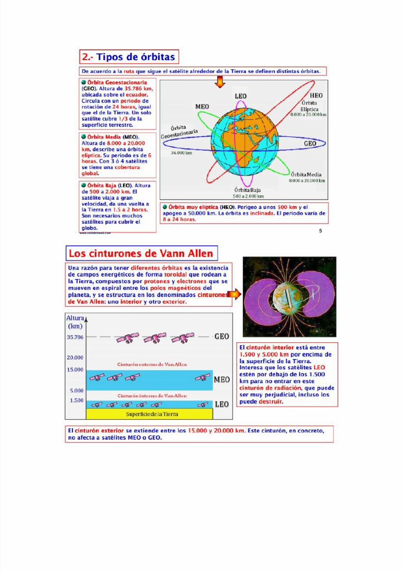
8112019 Tipos de oacuterbitasdocx
httpslidepdfcomreaderfulltipos-de-orbitasdocx 830
8112019 Tipos de oacuterbitasdocx
httpslidepdfcomreaderfulltipos-de-orbitasdocx 930
8112019 Tipos de oacuterbitasdocx
httpslidepdfcomreaderfulltipos-de-orbitasdocx 1030
8112019 Tipos de oacuterbitasdocx
httpslidepdfcomreaderfulltipos-de-orbitasdocx 1130
8112019 Tipos de oacuterbitasdocx
httpslidepdfcomreaderfulltipos-de-orbitasdocx 1230
Red Geodeacutesica Nacional Activa- conformada por 15 estaciones establecidas estrateacutegicamente los
cuales registran informaciones las 24 Hrs Del diacutea por los sateacutelites de la constelacioacuten navstar
Red Geodeacutesica Nacional Pasiva- constituida por 55324 veacutertices geodeacutesicos distribuidos en la Repuacuteblica
Mexicana conocido tambieacuten como ldquoEstaciones GPSrdquo y estaacuten materializadas sobre el terreno mediante
una placa que han sido realizados por los levantamientos con el GPS (Sistema de PosicionamientoGlobal) lo cual las dota de valores referenciales al elipsoide en consideracioacuten
8112019 Tipos de oacuterbitasdocx
httpslidepdfcomreaderfulltipos-de-orbitasdocx 1330
8112019 Tipos de oacuterbitasdocx
httpslidepdfcomreaderfulltipos-de-orbitasdocx 1430
DORIS
Introduction
The DORIS (Doppler Orbit determination and Radiopositioning Integrated on Satellite) system for satelliteorbit determination and precise positioning was developed by the Centre National drsquoEtudes Spatiales
( CNES) in conjunction with the Institut Geacuteographique National ( IGN) and the Groupe de Recherche deGeacuteodesie Spatiale ( GRGS)
A proof of concept for the International DORIS Service (IDS) was conducted through a pilot phase prior tothe establishment of the International DORIS Experiment in 1999 by the International Association ofGeodesy (IAG) The IDS formally began on July1 2003 after the IAG official approval at the IUGGGeneral Assembly in Sapporo
The IDS is an IAG Service and operates in close cooperation with the International Earth rotation and
Reference frames Service ( IERS)
The IDS mission
The primary objective of the IDS is to provide a service to support geodetic and geophysical researchactivities through DORIS data and derived products
The IDS collects archives and distributes DORIS observation data sets of sufficient accuracy to satisfythe objectives of a wide range of applications and experimentations From these data sets the followingproducts are derived
Coordinates and velocities of the IDS tracking stations
Geocenter and scale of the Terrestrial Reference Frame
High accuracy ephemerides of the DORIS satellites
Earth orientation parameters (EOPs)
The accuracies of these products are sufficient to support current scientific objectives including
Realization of global accessibility to and the improvement of the International Terrestrial ReferenceFrame ( ITRF)
Monitoring deformations of the solid Earth
Monitoring crustal deformation at tide gauges
Monitoring variations in the hydrosphere (sea level ice-sheets etc)
Orbit determination for scientific satellites
The IDS organization
The IDS accomplishes its mission through the following components
Satellites carrying a DORIS receiver
Network of tracking stations
Data Centers
Analysis centers and Analysis Coordinator
Combination Center
Working Groups
Central Bureau
Governing Board
8112019 Tipos de oacuterbitasdocx
httpslidepdfcomreaderfulltipos-de-orbitasdocx 1530
Satellites carrying a DORIS receiver
Since July 2003 the CNES and the European Space Agency ( ESA) have provided DORIS data to the IDS
Data from additional agencies are expected and welcome DORIS receivers are flown on LEO satellites
for precise orbit determination as well as for geodetic applications Satellites with DORIS receivers are
listed on the IDS website at httpids-dorisorg
A representative of the DORIS system serves as a voting member of the Governing Board
Network of Tracking Stations
The IDS network is composed of DORIS permanent tracking stations located at host institutions and
maintained by the IGN A list of the sites (past and present) is included on the IDS website at httpids-
dorisorg The network also includes additional DORIS stations proposed by the IDS to observe during
specific campaigns of scientific interest
A representative of the Network serves as a voting member of the Governing Board
Data Centers
The Data Centers are in direct contact with the CNES which provides the DORIS data The Data Centers
archive the DORIS data derived products and ancillary information required to process these data
A representative of the Data Centers serves as a voting member of the Governing Board
Analysis Centers and Analysis Coordinator
The Analysis Centers (ACs) are committed to provide at least one of the above IDS products on a regularbasis Expertise in DORIS data analysis and operational capability are essential factors in the selection of Analysis Centers
The Analysis Coordinator assists the Analysis Centers and monitors their activities to ensure that the IDS
objectives are carried out The Analysis Coordinator working with the Analysis Centers is expected toprovide quality control performance evaluation and continued development of appropriate analysisstandards The Analysis Coordinator with the support of the Combination Center is also responsible forthe appropriate combination of the Analysis Centers products into a single set of prescribed data products
The Analysis Coordinator and a representative of the Analysis Centers serve as voting members of the
Governing Board
Combination Center
The IDS appoints a Combination Center ( CC) to combine individual AC solutions and to generate IDS
data products for submission to the IERS for the formulation of the periodic update of the ITRF and
other geodetic products The CC is selected by the Governing Board every four years through a Call forParticipation initiated six months prior to the end of the current CC term Interested centers submit
proposals outlining their plan for operation of the CC and the resources that they will commit
A representative of the Combination Center serves as a voting member of the Governing Board
8112019 Tipos de oacuterbitasdocx
httpslidepdfcomreaderfulltipos-de-orbitasdocx 1630
Working Groups
IDS Working Groups provide expertise on particular topics related to the IDS components and on
development of particular IDS product(s) or service(s) relying on the IDS infrastructure All Working
Groups are created when needed and retired by the IDS Governing Board when their work has been
completed or they are no longer needed Each Working Group must develop a charter that includes a
mandate a list of specific tasks a schedule and an identified Chairperson
The Chairpersons of the Working Groups are non-voting members of the IDS Governing Board (see
below)
Central Bureau
The Central Bureau ( CB) is the executive arm of the IDS Governing Board and as such is responsible forthe general management of the IDS consistent with the directives policies and priorities set by theGoverning Board
In this role the CB within available resources coordinates IDS activities facilitates communicationsmaintains documentation and organizes reports meetings and workshops
The CB responds to external inquiries about the IDS promotes the use of IDS data and products andcoordinates interactions with other services including the IERS
The CB supports the Combination Center in combining the various Analysis Centers products andproviding all information necessary to validate the final combined products
The CB operates the information system for the IDS and produces the IDS Annual Reports and IDS Associates directory
The CB coordinates the publication of other documents required for the satisfactory planning and day-to-day operation of the Service including standards and specifications regarding the performancefunctionality and configuration requirements of all Service elements
Although the Chairperson of the Governing Board is the official representative of the IDS to externalorganizations the CB consistent with the directives established by the Governing Board is responsiblefor the day-to-day liaison with such organizations
The long-term function of the IDS is assured through redundancy and emergency contingency plan for allof its components except for the CB
The Central Bureau serves for a term of four years One year prior to the end of each term the GBformally reviews the performance of the Central Bureau At the behest of the GB the CB may be asked toreconfirm its commitment to serve another four years If the CB agrees it submits a proposal for GBapproval If the CB declines or if the GB chooses to change CB operators the GB announces a Call forProposals for a new IDS Central Bureau to take over responsibilities including a six-month transition
phase with the outgoing Central Bureau
In summary the Central Bureau performs primarily a long-term coordination role to ensure that IDS
participants contribute to the Service in a consistent and harmonious manner and adhere to IDS
standards
The Director of the Central Bureau serves as a voting member of the Governing Board
8112019 Tipos de oacuterbitasdocx
httpslidepdfcomreaderfulltipos-de-orbitasdocx 1730
Governing Board
The principal role of the Governing Board (GB) is to set policy and to exercise broad oversight of all IDS
functions and components It also controls general activities of the Service including restructuring
when appropriate to maintain Service efficiency and reliability
The Governing Board (GB) consists of eleven voting members and a number of non-voting membersThe membership is chosen to try to strike the right balance between project specialists and the generalcommunity The voting membership of the GB is distributed as follows
Elected by IDS Associates (see below)
Analysis Centers representative 1Data centers representative 1 Analysis Coordinator 1Members at large 2
Appointed members
Director of the Central Bureau 1IERS representative to IDS 1IAG representative to IDS 1Combination Center representative 1DORIS System representative (CNES)1Network representative (IGN) 1
Total number of voting members 11
During their mandate the Working Group chairpersons are GB members with voice but without vote
The elected members have staggered four-year terms with elections every two years
There is no limit to the number of terms that a person may serve however he or she may serve only twoterms consecutively as an elected member
The Analysis Centersrsquo representative the Data Centersrsquo representative and one Member -at-Large areelected during the first two-year election
The Analysis Coordinator and the other Member-at-Large are elected in the second two-year election
Although no formula is prescribed efforts should be made to keep the GB membership properly balancedwith regard to supporting organizations and geographic representation
Members of the GB become IAG Fellows with the appropriate rights and privileges as described on the
IAG website after an initial two-year period
GB elections
The GB elects a Chairperson from its members to serve a term of four years with the possibility of re-
election for one additional term The Chairperson does not vote on GB decisions except in the case of a
tie The Chairperson is the official representative of the IDS to external organizations
8112019 Tipos de oacuterbitasdocx
httpslidepdfcomreaderfulltipos-de-orbitasdocx 1830
Five members of the GB are elected by the IDS Associates A nominating committee conducts theelections for membership on the IDS Governing Board
The nominating committee consists of three members The Chair of the nominating committee isappointed by the Chair of the GB and must be a member of the GB not currently up for re-election TheGB chooses the remaining two members of the nominating committee from the list of IDS Associates Thenominating committee solicits nominations from the IDS Associates for each position to be filled at leasttwo candidates are required for each position
The Central Bureau runs the election
All IDS Associates are eligible to vote
Election is by a simple majority of votes received for each position
The two Member-at-Large positions are filled by the two candidates receiving the most votes a vote by
the GB will resolve any situation of a tie
Appointed Members
The IAG and IERS representatives to the IDS Governing Board are appointed respectively by the IAGExecutive Committee and by the IERS Directing Board for a maximum of two four-year terms
The DORIS System representative and the Network representative are appointed by CNES and IGNrespectively for four-year terms without limitation
The Director of the Central Bureau and the Combination Center representative are the two otherappointed members
In case of a resignation from the Governing Board the CB after consulting with the appropriate IDScomponents nominates a replacement candidate for election by the GB The replacement will serve untilthe end of the term of the resigned Board member
GB Decisions
Most decisions at GB meetings are to be made by consensus or by a simple majority vote of the voting
members present provided that there is a quorum consisting of at least six voting members of the GB
GB decisions can be made through email or other correspondence by a majority vote of the GB voting
membership Changes in the IDS Terms of Reference and Chairperson of the GB can only be made by a
23 majority of the members of the GB ie by seven or more votes
GB Meetings
The Board shall meet at least annually and at such other times as shall be considered appropriate by the
Chairperson or at the request of three members
The Central Bureau provides the secretariat of the GBIDS representatives to the IERS and the IAG
Through the existing reciprocity agreement between the IDS and the IERS the IDS Analysis Coordinator
serves as the DORIS Technique Center representative to IERS and as such subject to Governing Board
approval is a member of the IERS Directing Board (together with another person selected by the IDS
Governing Board) This arrangement ensures full cooperation between the two services
The IDS Governing Board will select the IDS representative to the IAG Executive Committee
8112019 Tipos de oacuterbitasdocx
httpslidepdfcomreaderfulltipos-de-orbitasdocx 1930
IDS Associates
IDS Associates are persons representing organizations that participate in any of the IDS components
A participating institution can submit a personrsquos name email and primary IDS function in its organizationto the Central Bureau for application to become an IDS Associate
The Governing Board approves all memberships
The Central Bureau maintains the current list of IDS Associates and makes the list available on the IDSwebsite
IDS Associates vote for the incoming Analysis Centersrsquo representative the Data Centersrsquo representativethe Analysis Coordinator and the Members-at-Large representatives as members of the GB
The GB must approve the list of IDS Associates eligible for voting in the elections at least three monthsprior to the election process
For the purposes of the election current and former GB members are also considered IDS Associates
IDS Associates are considered IAG Affiliates
After a decade of fully operational functioning the DORIS space geodesy system has demonstrated itscapabilities for orbitography and navigation of the satellites and also ground location It plays a key role inthe TopexPoseidon altimetric mission for oceanography providing in association with the Laser techniquea 2 cm accuracy in the radial component of the orbit DORIS and Laser are renewed as the nominalorbitographic system for the Jason mission (end of 2000)
DORIS also provides with Diode navigator on Spot 4 (1993) an orbit in real time within a few meters Itsa world first at this level of precision
Since 1994 and thanks to its more than fifty permanent beacon network DORIS contributes to
the IERS activities for the realization and maintenance of the ITRS (International Terrestrial ReferenceSystem) 3D positions and velocities of the reference sites at a cm and mmyr accuracy lead to scientificstudies (investigations) in the fields of global and regional tectonics Two recent DORIS results appearvery encouraging for the future One concerns a seasonal effect of earth surface fluid mass redistribution(oceanic water atmospheric masses snow ) on the relative positions of the earth mass and earthfigure centers Another concerns vertical displacement of the crust monitored near tides-gages Thisinformation is of major interest for the topic of sea level variations and correlation to the Global Change
Such as the other space geodesy techniques GPS VLBI SLR there is a strong demand among thescientific community to create an International DORIS Service so called IDS TheCSTG commission forinternational co-ordination of space techniques for geodesy of the International Association Geodesy( IAG) and the IERS directing board decided in July 1999 to initiate a DORIS Pilot Experiment Itsobjective was to assess the need and feasibility of an International DORIS Service
Since July1 2003 the International DORIS Service has been officially started as an IAGService after the decision of the IAG Executive Committtee at the IUGG General Assembly in SapporoNew terms of reference were released They describe the goals and organization of the IDS
8112019 Tipos de oacuterbitasdocx
httpslidepdfcomreaderfulltipos-de-orbitasdocx 2030
HOW ALTIMETRY WORKS
Altimetry satellites basically determine the distance from the satellite to a target surface by measuring
the satellite-to-surface round-trip time of a radar pulse However this is not the only measurement
made in the process and a lot of other information can be extracted from altimetry
The magnitude and shape of the echoes (or waveforms) also contain information about the
characteristics of the surface which caused the reflection The best results are obtained over the ocean
which is spatially homogeneous and has a surface which conforms with known statistics Surfaces which
are not homogeneous which contain discontinuities or significant slopes such as some ice rivers or
land surfaces make accurate interpretation more difficult
Basic principle
Radar altimeters permanently transmit signals to Earth and receive the echo from the surface The
satellite orbit have to be accurately tracked (Doris system) and its position is determined relative to an
arbitrary reference surface an ellipsoid The sea surface height (SSH) is the range from the sea surface
to a reference ellipsoid
8112019 Tipos de oacuterbitasdocx
httpslidepdfcomreaderfulltipos-de-orbitasdocx 2130
Pulses and waveforms
Altimetry satellites basically determine the distance from the satellite to a target surface by measuringthe satellite-to-surface round-trip time of a radar pulse The magnitude and shape of the echoes (orwaveforms) also contain information about the characteristics of the surface which caused thereflection
Frequencies used
Several different frequencies are used for radar altimeters Each frequency band has its advantagesand disadvantages sensitivity to atmospheric perturbations for Ku-band better observation of icerain coastal zones land masses for Ka-band
FUTURE TECHNOLOGY IMPROVEMENTS
Satellite altimetry has proven to be a valuable source of data for a broad range of applications Looking beyond the
missions in operational service today future satellites will need to provide better spatial and temporal coverage so
that we can study further near the coasts or mesoscale variations and other phenomena more closely For the
medium term consideration is now being given to altimetry missions capable of scanning the ocean surface to
acquire data at scales of a few tens of kilometres passing over the same spots every few days Other projects onthe drawing board are based on constellations of dedicated low-cost microsatellites The use of opportunity
signals is also being considered with the possibility of retrieving reflected signals transmitted by satellites in the
Global Navigation Satellite System (GNSS)
Altimeter-interferometers
An altimeterinterferometer would include several altimeters mounted on masts which would acquire
measurements simultaneously thus providing continuous single- or multi-altimeter wide-area
coverage ltbrgt Further information
Constellations
One of the ways to improve altimetry resolution is to use several satellites at the same time Until now this has
been done with very different types of satellite The use of several identical satellites in constellation could reduce
costs (development costs and launch costs too for micro-satellites launched by the same rocket)
GNSS altimetry
One approach being pursued to achieve maximum altimetry data coverage is to receive reflected signals
transmitted by satellites in the Global Navigation Satellite System (GNSS) in particular from the Global Positioning
System (GPS) constellation and its European civil counterpart Galileo This concept is based on a satellite in near-
polar orbit (at an altitude of 400 to 500 km) retrieving signals emitted by multiple satellites and reflected by the
ocean surface then analysing these signals to compute sea surface height This concept is currently still only in the
study phase
RADIOMETRY PRINCIPLE
Microwave remote sensing uses passive microwave radiometers The microwaves have wavelength ranging from a
few kHz to THz The ldquopassiverdquo term means that it uses microwaves naturally radiated by the observed area (this is
different from the radar principle where the sensor transmits a microwave signal towards a target and detects the
backscattered radiation)
Radiometry principle
8112019 Tipos de oacuterbitasdocx
httpslidepdfcomreaderfulltipos-de-orbitasdocx 2230
Radiometry principle
Satellite passive microwave radiometers measure raw antenna counts from which we determine the antenna
temperature and then calculate the brightness temperature of the Earth Large antennas are used for the various
channels of the radiometer and in operation each antenna feedhorn passes a hot and cold target in order toprovide consistently calibrated raw counts Brightness temperature is a measure of the radiance of microwave
radiation traveling upward from the top of Earths atmosphere The conversion from radiometer counts to top-of-
the-atmosphere (TOA) brightness temperature is called the calibration process Several calibration processing
steps are required to derive the brightness temperature values
Radiometry applications
Microwave radiometer brightness temperatures are considered as a fundamental climate data record
and are the values from which we derive ocean measurements of wind speed water vapor cloud liquid
water rain rate and sea surface temperature
Missions
The main passive microwave radiometers are listed below (instrumentsatellite)
AMSR-E on Aqua
SSMI on DMSP F08 F10 F11 F13 F14 F15
SSMIS on DMSP F16 F17
WindSat on Coriolis
TMI on TRMM
AMSR2 GCOM - W1
Radiometers and altimeters
In the altimetry domain interesting radiometers are those that are on-board altimetric missions such
as JMR MWR AMR Altika radiometer etc These microwave radiometers measure the total water
vapor along the path viewed by the altimeter In addition to measuring total water vapor they are used
for range correction and to measure brightness temperatures
8112019 Tipos de oacuterbitasdocx
httpslidepdfcomreaderfulltipos-de-orbitasdocx 2330
Using generally two (238 37 GHz for Altika radiometer on board SARAL) or three different frequencies
(eg 187 238 340GHz for the AMR on-board OSTMJason-2) measurements acquired at each
frequency are combined to determine atmospheric water vapor and liquid water content Once the
water content is known it is possible to determine the correction to be applied for radar signal path
delays
Altimetry missions that operate without radiometer (eg Cryosat-2) can use estimation of wet
tropospheric correction coming from atmospheric models
For more information
JMR instrument on-board Jason-1
AMR instrument on-board OSTMJason-2
MWR instrument on-board Envisat
AltiKa on-board SARAL
The International Laser Ranging Service (ILRS) provides global satellite and lunar laser ranging data and their related
products to support geodetic and geophysical research activities as well as IERS products important to the
maintenance of an accurate International Terrestrial Reference Frame (ITRF) The service develops the necessary
global standardsspecifications and encourages international adherence to its conventions The ILRS is one of the
space geodetic services of the International Association of Geodesy (IAG)
The ILRS collects merges archives and distributes Satellite Laser Ranging (SLR) and Lunar Laser Ranging (LLR)
observation data sets of sufficient accuracy to satisfy the objectives of a wide range of scientific engineering and
operational applications and experimentation These data sets are used by the ILRS to generate a number of
scientific and operational data products including
Earth orientation parameters (polar motion and length of day)
Station coordinates and velocities of the ILRS tracking systems
Time-varying geocenter coordinates
Static and time-varying coefficients of the Earths gravity field
Centimeter accuracy satellite ephemerides
Fundamental physical constants
Lunar ephemerides and librations
Lunar orientation parameters
The accuracy of SLRLLR data products is sufficient to support a variety of scientific and operational applications
including
Realization of global accessibility to and the improvement of the International Terrestrial Reference Frame
(ITRF)
Monitoring three dimensional deformations of the solid Earth
Monitoring Earth rotation and polar motion
8112019 Tipos de oacuterbitasdocx
httpslidepdfcomreaderfulltipos-de-orbitasdocx 2430
Support the monitoring of variations in the topography and volume of the liquid Earth (ocean circulation mean
sea level ice sheet thickness wave heights etc)
Tidally generated variations in atmospheric mass distribution
Calibration of microwave tracking techniques
Picosecond global time transfer experiments
Astrometric observations including determination of the dynamic equinox obliquity of the ecliptic and the
precession constant
Gravitational and general relativistic studies including Einsteins Equivalence Principle the Robertson-Walker b
parameter and time rate of change of the gravitational constant
Lunar physics including the dissipation of rotational energy shape of the core-mantle boundary (Love Number
k2) and free librations and stimulating mechanisms
Solar System ties to the International Celestial Reference Frame (ICRF)
Satellite Laser Ranging (SLR) and Lunar Laser Ranging (LLR) use short-pulse lasers and state-of-the-art opticalreceivers and timing electronics to measure the two-way time of flight (and hence distance) from ground stations toretroreflector arrays on Earth orbiting satellites and the Moon Scientific products derived using SLR and LLR datainclude precise geocentric positions and motions of ground stations satellite orbits components of Earthrsquos gravityfield and their temporal variations Earth Orientation Parameters (EOP) precise lunar ephemerides and informationabout the internal structure of the Moon Laser ranging systems are already measuring the one-way distance toremote optical receivers in space and can perform very accurate time transfer between sites far apart Laser rangingactivities are organized under the International Laser Ranging Service (ILRS) which provides global satellite andlunar laser ranging data and their derived data products to support research in geodesy geophysics Lunar scienceand fundamental constants This includes data products that are fundamental to the International TerrestrialReference Frame (ITRF) which is established and maintained by the International Earth Rotation and ReferenceSystems Service (IERS) The ILRS develops the necessary global standardsspecifications for laser ranging activitiesand encourages international adherence to its conventions
Analysis Products
The ILRS provides a service to utilize Satellite and Lunar Laser Ranging data to generate geodetic geodynamic andgeophysical scientific products
Currently five SLR analysis groups (ASI DGFI GFZ JCET and NSGF) provide direct input for the official ILRSproducts (stationcoordinates and Earth Orientation Parameters EOPs) The results of the ILRS POS+EOP pilot project wereevaluated during the AWG meeting in San Fernando The five contributors were acknowledged and given an officialstatus In addition ASI was selected as the official ILRS primary combination center and DGFI was selected as theofficial ILRS backup combination center each for a two-year term As well as the contributors of individual solutionsthese combination centers must follow strict timelines and provide routine products of the highest possible qualityWeekly official ILRS products from these two combination centers are now available in SINEX format eachWednesday at CDDIS and EDC Analysis centers will again compete for the ILRS combination and backup center in
mid-2006 at the International Laser Ranging Workshop in Australia All groups are encouraged to develop (thequality of) their contributions furtherThe ILRS now generates weekly unconstrained solutions for station coordinates (valid for the mid-point of each 7-day interval) and EOPs (x-pole y-pole and Length-Of-Day (LOD) all of them for 1-day intervals) These results arestored in subdirectories of the form pos+eopYYMMDD where YYMMDD is the date (YY =2 digit year MM =2 digitmonth and DD=2 digit day) of the end of each 7-day interval Within each subdirectory one finds so-called individualsolutions and combination solutions that are explained belowFor the individual contributions to the POS+EOPproject filenames are of the form (examples reflect CDDIS archive)ftpcddisgsfcnasagovpubslrproductspos+eopYYMMDDCENTER pos+eopYYMMDDv1snxZHere CENTER is replaced by the name of the actual contributor It is the first solution that is generated for thisperiod and by this analysis center hence v1 If re-computations are necessary the version number will be
8112019 Tipos de oacuterbitasdocx
httpslidepdfcomreaderfulltipos-de-orbitasdocx 2530
increased by one solutions for new weeks will start with v1 however The results are stored in the SINEX format(snx) The reader is refered to the COMMENTS section of each solution (in the file itself) or more generalexplanations of SINEX for further details of the solution andor the formatThe official ILRS primary product on POS+EOP is labeled as
ftpcddisgsfcnasagovpubslrproductspos+eopYYMMDDilrsapos+eopYYMMDDv1snxZIn a similar fashion the EOP solutions (wrt ITRF2000) generated by the official ILRS primary combination centerare named
ftpcddisgsfcnasagovpubslrproductspos+eopYYMMDDilrsaeopYYMMDDv1snxZThe ILRS also has an official backup combination center and its products are labeled
ftpcddisgsfcnasagovpubslrproductspos+eopYYMMDDilrsbpos+eopYYMMDDv1snxZftpcddisgsfcnasagovpubslrproductspos+eopYYMMDDilrsbeopYYMMDDv1snxZCurrently the ILRS AWG is in the process of computing similar solutions for the years before the workshop in SanFernando At this moment the AWG works on solutions going back to the launch date of LAGEOS-2 (ie November1992) It is foreseen that this will (at a later stage) be followed by computations for the time frame extending back toSeptember 1983 the beginning of the MERIT campaign
Historical products include
Earth Orientation Parameters (EOP)o GSFC 98L01 solution
o CSR 95L01 solutiono Delft University of Technology 92L01 solutiono GeoForschungsZentrum 95L01 solutiono Centro di Geodesia Spaziale solutions
Coordinates and velocities of the tracking stations
Geocenter coordinates - IERS Geocenter campaign results IERS TN25
In Satellite Laser Ranging a short pulse of coherent light generated by a laser (Light Amplification by Stimulated
Emission of Radiation) is transmitted in a narrow beam to illuminate corner cube retroreflectors on the satellite Thereturn signal typically a few photons is collected by a telescope and the time-of-flight is measured Using informationabout the satellitersquos orbit the time-of-flight and the speed of light the location of the ranging station can bedetermined Similar data acquired by another station many kilometers distant from the first or on a different continentcan be used to determine the distance between stations to precisions of centimeters or better Repetitivemeasurements over months and years yield the changein distance or the motion of the Earthrsquos crust
Laser ranging to a near-Earth satellite was initiated byNASA in 1964 with the launch of the Beacon-B satelliteSince that time ranging precision spurred by scientificrequirements has improved by a factor of a thousandfrom a few meters to a few millimeters Similarly thenetwork of laser stations has grown from a fewexperimental sites to a global network of 43 stations inmore than 30 countries Most of these stations (33) arefunded by organizations other than NASA
During the past three decades the global Satellite LaserRanging (SLR) network has evolved into a powerfulsource of data for studies of the solid Earth and itsocean and atmospheric systems including
Detection and monitoring of tectonic plate motioncrustal deformation Earth rotation and polar motion
Modeling of the spatial and temporal variations of the Earthrsquos gravitational field
Determination of basin-scale ocean tides
Monitoring of millimeter-level variations in the location of the center of mass of the total Earth system (solidEarth-atmosphere-oceans)
Establishment and maintenance of the International Terrestrial Reference System (ITRS) and
Detection and monitoring of post-glacial rebound and subsidence
8112019 Tipos de oacuterbitasdocx
httpslidepdfcomreaderfulltipos-de-orbitasdocx 2630
In addition SLR provides precise orbit determination for spaceborne radar altimeter missions mapping the oceansurface (which are used to model global ocean circulation) for mapping volumetric changes in continental ice massesand for land topography It provides a means for subnanosecond global time transfer and a basis for special tests ofthe Theory of General Relativity
SLR uses special passive spacecraft in very stable orbits A low area to mass ratio minimizes the effects ofatmospheric drag and solar radiation pressure on the satellitersquos orbit
An example of such a satellite is the Laser Geodynamics Satellite (LAGEOS-1) which was launched by the UnitedStates in 1976 into a 6000 kilometer circular orbit with a near polar inclination Lageos-I and its sister satelliteLageos-II (built by the Agenzia Spaziale Italiana of Italy and launched in 1992 into a 6000 kilometer orbit but with aninclination of 51 degrees) have a 60 centimeter spherical shape and weigh 411 kilograms The exterior surface ofboth satellites is covered by 426 retroreflectors
Other satellites for SLR include Starlette (1000 km) and Stella (800 km) developed and launched by France Etalon-Iand -2 (19000 km) developed and launched by the former USSR and Ajisai (1500 km) developed and launched byJapan To obtain data for precise orbit determination retroreflectors are also mounted on the USFranceTopexPoseidon spacecraft the European Space Agency Earth Remote Sensing satellites (ERS-1 and 2) and on afew of the United States Global Positioning System (GPS) satellites
Fixed and mobile SLR systems have been used to acquire data for studies of crustal deformation and plate motion atscales from several hundred kilometers to several thousand kilometers to monitor polar motion and Earth rotationand to model the Earthrsquos gravity field
Lunar Laser Ranging (LLR)
During three US American Apollo missions (11 14 and 15) and two unmanned Soviet missions (Luna 17 and Luna21) retro-reflectors were deployed near the lunar landing sites between 1969 and 1973 The Lunar Laser Ranging(LLR) experiment has continuously provided range data for about 41 years generating about 17000 normal pointsThe main benefit of this space geodetic technique is the determination of a host of parameters describing lunarephemeris lunar physics the Moons interior various reference frames Earth orientation parameters and the Earth-Moon dynamics LLR has also become one of the strongest tools for testing Einsteins theory of general relativity inthe solar system no violations of general relativity have been found so far However the basis for all scientificanalyses is more high quality data from a well-distributed global LLR network More information is provided onthe LLR page
SLR and LLR are used in the following scientific research
Atmosphere-Hydrosphere-Cryosphere-Solid Earth Interactions Long-Term Dynamics of the Solid Earth Oceans and Ice Fields
Tides
Sensing of surface elevations
Mantle
Lunar Science
About IVS
Overview of IVS
IVS is an international collaboration of organizations which operate or support Very Long Baseline Interferometry(VLB I) components
The objectives of IVS are
to provide a service to support geodetic geophysical and astrometric research and operational activities
to promote research and development activities in all aspects of the geodetic and astrometric VLBI technique and
to interact with the community of users of VLBI products and to integrate VLBI into a global Earth observing system
The service aspect of IVS is meant to serve both outside users and the geodetic and astrometric community itselfBoth the contributors and users of data will be served
8112019 Tipos de oacuterbitasdocx
httpslidepdfcomreaderfulltipos-de-orbitasdocx 2730
IVS provides data and products for the scientific community Some of the products are
a terrestrial reference frame (TRF)
the international celestial reference frame (ICRF) and
Earth orientation parameters (EOP)
All IVS data and products are archived in data centers and are publically available for research in relatedareas of geodesy geophysics and astrometry
General The IVS observing program consists of various series of 24-hour observing sessions The
program is planned by the Observing Program Committee coordinated by the IVS Coordinating Center and
executed by the Network Stations Operation Centers andCorrelators The result of the observing program is
the data held in the Data Centers that is then available for analysis The flow of data and the resulting
products are shown graphically on the IVS structure and flow diagram Auxiliary data files such as schedule
and notes files are used to facilitate the observing operations They can be accessed from the IVS
Datapage or following procedures outlined in the Download Schedules page
IVS Live Following the success of the dynamic Web site for the IYA09 session Laboratoire
dAstrophysique de Bordeaux developed a generalized version of this tool for the entire IVS observingplan The resulting IVS Live site allows the user to monitor each session in real-time in terms of stations
scans and sources being used It provides links to Webcams and further ancillary information Follow
the countdown to the next IVS session or check out past or future IVS sessions using the session
calendar Many thanks to Arnaud Collioud and Bordeaux Observatory for making this possible
IVS Network Stations acquire geodetic and astrometric VLBI data Data acquisition at Network Stations is
controlled by schedules prepared by Operation Centers The raw data and log files are transmitted to
the Correlators for processing Details of the planned sessions are published in the Master Files maintained
by the Coordinating Center
About the IGS
The IGS global system of satellite tracking stations Data Centers and Analysis
Centers puts high-quality GPS data and data products on line in near real time to
meet the objectives of a wide range of scientific and engineering applications and
studies
The IGS collects archives and distributes GPS observation data sets of sufficientaccuracy to satisfy the objectives of a wide range of applications and experimentationThese data sets are used by the IGS to generate the data products mentioned abovewhich are made available to interested users through the Internet In particular theaccuracies of IGS products are sufficient for the improvement and extension of theInternational Terrestrial Reference Frame (ITRF) the monitoring of solid Earthdeformations the monitoring of Earth rotation and variations in the liquid Earth (sealevel ice-sheets etc) for scientific satellite orbit determinations ionospheremonitoring and recovery of precipitable water vapor measurements
8112019 Tipos de oacuterbitasdocx
httpslidepdfcomreaderfulltipos-de-orbitasdocx 2830
Mission
The primary mission of the International GPS Service as stated in the organizations
2002-2007 Strategic Plan is
The International GPS Service is committed to providing the highest quality data
and products as the standard for global navigation satellite systems (GNSS) in
support of Earth science research multidisciplinary applications and education
These activities aim to advance scientific understanding of the Earth system
components and their interactions as well as to facilitate other applications
benefiting society
The IGS Terms of Reference (comparable to the by-laws of the organization)describes in broad terms the goals and organization of the IGS
To accomplish its mission the IGS has a number of components an internationalnetwork of over 350 continuously operating dual-frequency GPS stations more than adozen regional and operational data centers three global data centers seven analysiscenters and a number of associate or regional analysis centers The Central Bureau forthe service is located at the Jet Propulsion Laboratory which maintains the CentralBureau Information System (CBIS) and ensures access to IGS products andinformation An international Governing Board oversees all aspects of the IGS TheIGS is an approved service of the International Association of Geodesy since 1994and is recognized as a member of the Federation of Astronomical and Geophysical
Data Analysis Services (FAGS) since 1996
For more information concerning IGS organization click here
History
Since the late 1980s the US Global Positioning System (GPS) constellation ofsatellites has come to play a major role in regional and global studies of Earth In theface of continued growth and diversification of GPS applications the worldwidescientific community has made an effort to promote international standards for GPS
data acquisition and analysis and to deploy and operate a common comprehensiveglobal tracking system
As part of this effort the IGS was formally recognized in 1993 by the InternationalAssociation of Geodesy (IAG) and began routine operations on January 1 1994 providing GPS orbits tracking data and other data products in support of geodeticand geophysical research In particular since January 1994 the IGS has madeavailable to its user community the IGS official orbit based on contributions from the
8112019 Tipos de oacuterbitasdocx
httpslidepdfcomreaderfulltipos-de-orbitasdocx 2930
seven current IGS Analysis Centers The IGS also supports a variety of governmentaland commercial activities and develops international GPS data standards andspecifications A description of the development and evolution of the IGS can befound in a number of publications with detailed documentation contained in the IGSAnnual Report Series published by the IGS Central Bureau via the World Wide WebThis series contains the yearly contributions from all components of service anddemonstrates that the key to success of the IGS has been the broad support of theinternational geodynamics and geodetic communities and their sponsoringorganizations This Information System is sponsored by the National Aeronautic andSpace Administration ( NASA) and managed for NASA by the Jet PropulsionLaboratory (JPL) of the California Institute of Technology (Caltech)
Operations
The IGS has developed a worldwide system comprising satellite tracking stations
Data Centers and Analysis Centers to put high-quality GPS data and data productson line within a day of observations For example following the NorthridgeCalifornia earthquake in January 1994 analysis teams using IGS-supplied data and products were able to quickly evaluate the disasters immediate effects by determiningstation displacements accurately to within a few millimeters
The IGS global network of permanent tracking stations each equipped with a GPSreceiver generates raw orbit and tracking data The Operational Data Centers whichare in direct contact with the tracking sites collect the raw receiver data and formatthem according to a common standard using a data format called Receiver
Independent Exchange (RINEX) The formatted data are then forwarded to theRegional or Global Data Centers To reduce electronic network traffic the RegionalData Centers are used to collect data from several Operational Data Centers beforetransmitting them to the Global Data Centers Data not used for global analyses arearchived and available for online access at the Regional Data Centers The GlobalData Centers archive and provide on-line access to tracking data and data products
Products and Applications
The IGS collects archives and distributes GPS observation data sets of sufficient
accuracy to meet the objectives of a wide range of scientific and engineeringapplications and studies These data sets are used to generate the following products
GPS satellite ephemerides
GLONASS satellite ephemerides
Earth rotation parameters
IGS tracking station coordinates and velocities
8112019 Tipos de oacuterbitasdocx
httpslidepdfcomreaderfulltipos-de-orbitasdocx 3030
GPS satellite and IGS tracking station clock information
Zenith tropospheric path delay estimates
Global ionospheric maps
IGS products support scientific activities such as improving and extending theInternational Earth Rotation Service (IERS) Terrestrial Reference Frame (ITRF)monitoring deformations of the solid Earth and variations in the liquid Earth (sea levelice sheets etc) and in Earth rotation determining orbits of scientific satellites andmonitoring the ionosphere For example geodynamics investigators who use GPS inlocal regions can include data from one or more nearby IGS stations fix the sitecoordinates from such stations to their ITRF values and more importantly use the precise IGS orbits without further refinement Data from an investigators localnetwork can then be analyzed with maximum accuracy and minimum computational burden Furthermore the results will be in a well-defined global reference frame
An additional aspect of IGS products is for the densification of the ITRF at a moreregional level This is accomplished through the rigorous combination of regional orlocal network solutions utilizing the Solution Independent Exchange Format (SINEX) and a process defined in the densification section
In the future the IGS infrastructure could become a valuable asset for support of newground-based applications and could also contribute to space-based missions inwhich highly accurate flight and ground differential techniques are required
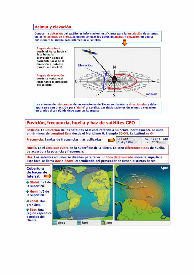
8112019 Tipos de oacuterbitasdocx
httpslidepdfcomreaderfulltipos-de-orbitasdocx 1430
DORIS
Introduction
The DORIS (Doppler Orbit determination and Radiopositioning Integrated on Satellite) system for satelliteorbit determination and precise positioning was developed by the Centre National drsquoEtudes Spatiales
( CNES) in conjunction with the Institut Geacuteographique National ( IGN) and the Groupe de Recherche deGeacuteodesie Spatiale ( GRGS)
A proof of concept for the International DORIS Service (IDS) was conducted through a pilot phase prior tothe establishment of the International DORIS Experiment in 1999 by the International Association ofGeodesy (IAG) The IDS formally began on July1 2003 after the IAG official approval at the IUGGGeneral Assembly in Sapporo
The IDS is an IAG Service and operates in close cooperation with the International Earth rotation and
Reference frames Service ( IERS)
The IDS mission
The primary objective of the IDS is to provide a service to support geodetic and geophysical researchactivities through DORIS data and derived products
The IDS collects archives and distributes DORIS observation data sets of sufficient accuracy to satisfythe objectives of a wide range of applications and experimentations From these data sets the followingproducts are derived
Coordinates and velocities of the IDS tracking stations
Geocenter and scale of the Terrestrial Reference Frame
High accuracy ephemerides of the DORIS satellites
Earth orientation parameters (EOPs)
The accuracies of these products are sufficient to support current scientific objectives including
Realization of global accessibility to and the improvement of the International Terrestrial ReferenceFrame ( ITRF)
Monitoring deformations of the solid Earth
Monitoring crustal deformation at tide gauges
Monitoring variations in the hydrosphere (sea level ice-sheets etc)
Orbit determination for scientific satellites
The IDS organization
The IDS accomplishes its mission through the following components
Satellites carrying a DORIS receiver
Network of tracking stations
Data Centers
Analysis centers and Analysis Coordinator
Combination Center
Working Groups
Central Bureau
Governing Board
8112019 Tipos de oacuterbitasdocx
httpslidepdfcomreaderfulltipos-de-orbitasdocx 1530
Satellites carrying a DORIS receiver
Since July 2003 the CNES and the European Space Agency ( ESA) have provided DORIS data to the IDS
Data from additional agencies are expected and welcome DORIS receivers are flown on LEO satellites
for precise orbit determination as well as for geodetic applications Satellites with DORIS receivers are
listed on the IDS website at httpids-dorisorg
A representative of the DORIS system serves as a voting member of the Governing Board
Network of Tracking Stations
The IDS network is composed of DORIS permanent tracking stations located at host institutions and
maintained by the IGN A list of the sites (past and present) is included on the IDS website at httpids-
dorisorg The network also includes additional DORIS stations proposed by the IDS to observe during
specific campaigns of scientific interest
A representative of the Network serves as a voting member of the Governing Board
Data Centers
The Data Centers are in direct contact with the CNES which provides the DORIS data The Data Centers
archive the DORIS data derived products and ancillary information required to process these data
A representative of the Data Centers serves as a voting member of the Governing Board
Analysis Centers and Analysis Coordinator
The Analysis Centers (ACs) are committed to provide at least one of the above IDS products on a regularbasis Expertise in DORIS data analysis and operational capability are essential factors in the selection of Analysis Centers
The Analysis Coordinator assists the Analysis Centers and monitors their activities to ensure that the IDS
objectives are carried out The Analysis Coordinator working with the Analysis Centers is expected toprovide quality control performance evaluation and continued development of appropriate analysisstandards The Analysis Coordinator with the support of the Combination Center is also responsible forthe appropriate combination of the Analysis Centers products into a single set of prescribed data products
The Analysis Coordinator and a representative of the Analysis Centers serve as voting members of the
Governing Board
Combination Center
The IDS appoints a Combination Center ( CC) to combine individual AC solutions and to generate IDS
data products for submission to the IERS for the formulation of the periodic update of the ITRF and
other geodetic products The CC is selected by the Governing Board every four years through a Call forParticipation initiated six months prior to the end of the current CC term Interested centers submit
proposals outlining their plan for operation of the CC and the resources that they will commit
A representative of the Combination Center serves as a voting member of the Governing Board
8112019 Tipos de oacuterbitasdocx
httpslidepdfcomreaderfulltipos-de-orbitasdocx 1630
Working Groups
IDS Working Groups provide expertise on particular topics related to the IDS components and on
development of particular IDS product(s) or service(s) relying on the IDS infrastructure All Working
Groups are created when needed and retired by the IDS Governing Board when their work has been
completed or they are no longer needed Each Working Group must develop a charter that includes a
mandate a list of specific tasks a schedule and an identified Chairperson
The Chairpersons of the Working Groups are non-voting members of the IDS Governing Board (see
below)
Central Bureau
The Central Bureau ( CB) is the executive arm of the IDS Governing Board and as such is responsible forthe general management of the IDS consistent with the directives policies and priorities set by theGoverning Board
In this role the CB within available resources coordinates IDS activities facilitates communicationsmaintains documentation and organizes reports meetings and workshops
The CB responds to external inquiries about the IDS promotes the use of IDS data and products andcoordinates interactions with other services including the IERS
The CB supports the Combination Center in combining the various Analysis Centers products andproviding all information necessary to validate the final combined products
The CB operates the information system for the IDS and produces the IDS Annual Reports and IDS Associates directory
The CB coordinates the publication of other documents required for the satisfactory planning and day-to-day operation of the Service including standards and specifications regarding the performancefunctionality and configuration requirements of all Service elements
Although the Chairperson of the Governing Board is the official representative of the IDS to externalorganizations the CB consistent with the directives established by the Governing Board is responsiblefor the day-to-day liaison with such organizations
The long-term function of the IDS is assured through redundancy and emergency contingency plan for allof its components except for the CB
The Central Bureau serves for a term of four years One year prior to the end of each term the GBformally reviews the performance of the Central Bureau At the behest of the GB the CB may be asked toreconfirm its commitment to serve another four years If the CB agrees it submits a proposal for GBapproval If the CB declines or if the GB chooses to change CB operators the GB announces a Call forProposals for a new IDS Central Bureau to take over responsibilities including a six-month transition
phase with the outgoing Central Bureau
In summary the Central Bureau performs primarily a long-term coordination role to ensure that IDS
participants contribute to the Service in a consistent and harmonious manner and adhere to IDS
standards
The Director of the Central Bureau serves as a voting member of the Governing Board
8112019 Tipos de oacuterbitasdocx
httpslidepdfcomreaderfulltipos-de-orbitasdocx 1730
Governing Board
The principal role of the Governing Board (GB) is to set policy and to exercise broad oversight of all IDS
functions and components It also controls general activities of the Service including restructuring
when appropriate to maintain Service efficiency and reliability
The Governing Board (GB) consists of eleven voting members and a number of non-voting membersThe membership is chosen to try to strike the right balance between project specialists and the generalcommunity The voting membership of the GB is distributed as follows
Elected by IDS Associates (see below)
Analysis Centers representative 1Data centers representative 1 Analysis Coordinator 1Members at large 2
Appointed members
Director of the Central Bureau 1IERS representative to IDS 1IAG representative to IDS 1Combination Center representative 1DORIS System representative (CNES)1Network representative (IGN) 1
Total number of voting members 11
During their mandate the Working Group chairpersons are GB members with voice but without vote
The elected members have staggered four-year terms with elections every two years
There is no limit to the number of terms that a person may serve however he or she may serve only twoterms consecutively as an elected member
The Analysis Centersrsquo representative the Data Centersrsquo representative and one Member -at-Large areelected during the first two-year election
The Analysis Coordinator and the other Member-at-Large are elected in the second two-year election
Although no formula is prescribed efforts should be made to keep the GB membership properly balancedwith regard to supporting organizations and geographic representation
Members of the GB become IAG Fellows with the appropriate rights and privileges as described on the
IAG website after an initial two-year period
GB elections
The GB elects a Chairperson from its members to serve a term of four years with the possibility of re-
election for one additional term The Chairperson does not vote on GB decisions except in the case of a
tie The Chairperson is the official representative of the IDS to external organizations
8112019 Tipos de oacuterbitasdocx
httpslidepdfcomreaderfulltipos-de-orbitasdocx 1830
Five members of the GB are elected by the IDS Associates A nominating committee conducts theelections for membership on the IDS Governing Board
The nominating committee consists of three members The Chair of the nominating committee isappointed by the Chair of the GB and must be a member of the GB not currently up for re-election TheGB chooses the remaining two members of the nominating committee from the list of IDS Associates Thenominating committee solicits nominations from the IDS Associates for each position to be filled at leasttwo candidates are required for each position
The Central Bureau runs the election
All IDS Associates are eligible to vote
Election is by a simple majority of votes received for each position
The two Member-at-Large positions are filled by the two candidates receiving the most votes a vote by
the GB will resolve any situation of a tie
Appointed Members
The IAG and IERS representatives to the IDS Governing Board are appointed respectively by the IAGExecutive Committee and by the IERS Directing Board for a maximum of two four-year terms
The DORIS System representative and the Network representative are appointed by CNES and IGNrespectively for four-year terms without limitation
The Director of the Central Bureau and the Combination Center representative are the two otherappointed members
In case of a resignation from the Governing Board the CB after consulting with the appropriate IDScomponents nominates a replacement candidate for election by the GB The replacement will serve untilthe end of the term of the resigned Board member
GB Decisions
Most decisions at GB meetings are to be made by consensus or by a simple majority vote of the voting
members present provided that there is a quorum consisting of at least six voting members of the GB
GB decisions can be made through email or other correspondence by a majority vote of the GB voting
membership Changes in the IDS Terms of Reference and Chairperson of the GB can only be made by a
23 majority of the members of the GB ie by seven or more votes
GB Meetings
The Board shall meet at least annually and at such other times as shall be considered appropriate by the
Chairperson or at the request of three members
The Central Bureau provides the secretariat of the GBIDS representatives to the IERS and the IAG
Through the existing reciprocity agreement between the IDS and the IERS the IDS Analysis Coordinator
serves as the DORIS Technique Center representative to IERS and as such subject to Governing Board
approval is a member of the IERS Directing Board (together with another person selected by the IDS
Governing Board) This arrangement ensures full cooperation between the two services
The IDS Governing Board will select the IDS representative to the IAG Executive Committee
8112019 Tipos de oacuterbitasdocx
httpslidepdfcomreaderfulltipos-de-orbitasdocx 1930
IDS Associates
IDS Associates are persons representing organizations that participate in any of the IDS components
A participating institution can submit a personrsquos name email and primary IDS function in its organizationto the Central Bureau for application to become an IDS Associate
The Governing Board approves all memberships
The Central Bureau maintains the current list of IDS Associates and makes the list available on the IDSwebsite
IDS Associates vote for the incoming Analysis Centersrsquo representative the Data Centersrsquo representativethe Analysis Coordinator and the Members-at-Large representatives as members of the GB
The GB must approve the list of IDS Associates eligible for voting in the elections at least three monthsprior to the election process
For the purposes of the election current and former GB members are also considered IDS Associates
IDS Associates are considered IAG Affiliates
After a decade of fully operational functioning the DORIS space geodesy system has demonstrated itscapabilities for orbitography and navigation of the satellites and also ground location It plays a key role inthe TopexPoseidon altimetric mission for oceanography providing in association with the Laser techniquea 2 cm accuracy in the radial component of the orbit DORIS and Laser are renewed as the nominalorbitographic system for the Jason mission (end of 2000)
DORIS also provides with Diode navigator on Spot 4 (1993) an orbit in real time within a few meters Itsa world first at this level of precision
Since 1994 and thanks to its more than fifty permanent beacon network DORIS contributes to
the IERS activities for the realization and maintenance of the ITRS (International Terrestrial ReferenceSystem) 3D positions and velocities of the reference sites at a cm and mmyr accuracy lead to scientificstudies (investigations) in the fields of global and regional tectonics Two recent DORIS results appearvery encouraging for the future One concerns a seasonal effect of earth surface fluid mass redistribution(oceanic water atmospheric masses snow ) on the relative positions of the earth mass and earthfigure centers Another concerns vertical displacement of the crust monitored near tides-gages Thisinformation is of major interest for the topic of sea level variations and correlation to the Global Change
Such as the other space geodesy techniques GPS VLBI SLR there is a strong demand among thescientific community to create an International DORIS Service so called IDS TheCSTG commission forinternational co-ordination of space techniques for geodesy of the International Association Geodesy( IAG) and the IERS directing board decided in July 1999 to initiate a DORIS Pilot Experiment Itsobjective was to assess the need and feasibility of an International DORIS Service
Since July1 2003 the International DORIS Service has been officially started as an IAGService after the decision of the IAG Executive Committtee at the IUGG General Assembly in SapporoNew terms of reference were released They describe the goals and organization of the IDS
8112019 Tipos de oacuterbitasdocx
httpslidepdfcomreaderfulltipos-de-orbitasdocx 2030
HOW ALTIMETRY WORKS
Altimetry satellites basically determine the distance from the satellite to a target surface by measuring
the satellite-to-surface round-trip time of a radar pulse However this is not the only measurement
made in the process and a lot of other information can be extracted from altimetry
The magnitude and shape of the echoes (or waveforms) also contain information about the
characteristics of the surface which caused the reflection The best results are obtained over the ocean
which is spatially homogeneous and has a surface which conforms with known statistics Surfaces which
are not homogeneous which contain discontinuities or significant slopes such as some ice rivers or
land surfaces make accurate interpretation more difficult
Basic principle
Radar altimeters permanently transmit signals to Earth and receive the echo from the surface The
satellite orbit have to be accurately tracked (Doris system) and its position is determined relative to an
arbitrary reference surface an ellipsoid The sea surface height (SSH) is the range from the sea surface
to a reference ellipsoid
8112019 Tipos de oacuterbitasdocx
httpslidepdfcomreaderfulltipos-de-orbitasdocx 2130
Pulses and waveforms
Altimetry satellites basically determine the distance from the satellite to a target surface by measuringthe satellite-to-surface round-trip time of a radar pulse The magnitude and shape of the echoes (orwaveforms) also contain information about the characteristics of the surface which caused thereflection
Frequencies used
Several different frequencies are used for radar altimeters Each frequency band has its advantagesand disadvantages sensitivity to atmospheric perturbations for Ku-band better observation of icerain coastal zones land masses for Ka-band
FUTURE TECHNOLOGY IMPROVEMENTS
Satellite altimetry has proven to be a valuable source of data for a broad range of applications Looking beyond the
missions in operational service today future satellites will need to provide better spatial and temporal coverage so
that we can study further near the coasts or mesoscale variations and other phenomena more closely For the
medium term consideration is now being given to altimetry missions capable of scanning the ocean surface to
acquire data at scales of a few tens of kilometres passing over the same spots every few days Other projects onthe drawing board are based on constellations of dedicated low-cost microsatellites The use of opportunity
signals is also being considered with the possibility of retrieving reflected signals transmitted by satellites in the
Global Navigation Satellite System (GNSS)
Altimeter-interferometers
An altimeterinterferometer would include several altimeters mounted on masts which would acquire
measurements simultaneously thus providing continuous single- or multi-altimeter wide-area
coverage ltbrgt Further information
Constellations
One of the ways to improve altimetry resolution is to use several satellites at the same time Until now this has
been done with very different types of satellite The use of several identical satellites in constellation could reduce
costs (development costs and launch costs too for micro-satellites launched by the same rocket)
GNSS altimetry
One approach being pursued to achieve maximum altimetry data coverage is to receive reflected signals
transmitted by satellites in the Global Navigation Satellite System (GNSS) in particular from the Global Positioning
System (GPS) constellation and its European civil counterpart Galileo This concept is based on a satellite in near-
polar orbit (at an altitude of 400 to 500 km) retrieving signals emitted by multiple satellites and reflected by the
ocean surface then analysing these signals to compute sea surface height This concept is currently still only in the
study phase
RADIOMETRY PRINCIPLE
Microwave remote sensing uses passive microwave radiometers The microwaves have wavelength ranging from a
few kHz to THz The ldquopassiverdquo term means that it uses microwaves naturally radiated by the observed area (this is
different from the radar principle where the sensor transmits a microwave signal towards a target and detects the
backscattered radiation)
Radiometry principle
8112019 Tipos de oacuterbitasdocx
httpslidepdfcomreaderfulltipos-de-orbitasdocx 2230
Radiometry principle
Satellite passive microwave radiometers measure raw antenna counts from which we determine the antenna
temperature and then calculate the brightness temperature of the Earth Large antennas are used for the various
channels of the radiometer and in operation each antenna feedhorn passes a hot and cold target in order toprovide consistently calibrated raw counts Brightness temperature is a measure of the radiance of microwave
radiation traveling upward from the top of Earths atmosphere The conversion from radiometer counts to top-of-
the-atmosphere (TOA) brightness temperature is called the calibration process Several calibration processing
steps are required to derive the brightness temperature values
Radiometry applications
Microwave radiometer brightness temperatures are considered as a fundamental climate data record
and are the values from which we derive ocean measurements of wind speed water vapor cloud liquid
water rain rate and sea surface temperature
Missions
The main passive microwave radiometers are listed below (instrumentsatellite)
AMSR-E on Aqua
SSMI on DMSP F08 F10 F11 F13 F14 F15
SSMIS on DMSP F16 F17
WindSat on Coriolis
TMI on TRMM
AMSR2 GCOM - W1
Radiometers and altimeters
In the altimetry domain interesting radiometers are those that are on-board altimetric missions such
as JMR MWR AMR Altika radiometer etc These microwave radiometers measure the total water
vapor along the path viewed by the altimeter In addition to measuring total water vapor they are used
for range correction and to measure brightness temperatures
8112019 Tipos de oacuterbitasdocx
httpslidepdfcomreaderfulltipos-de-orbitasdocx 2330
Using generally two (238 37 GHz for Altika radiometer on board SARAL) or three different frequencies
(eg 187 238 340GHz for the AMR on-board OSTMJason-2) measurements acquired at each
frequency are combined to determine atmospheric water vapor and liquid water content Once the
water content is known it is possible to determine the correction to be applied for radar signal path
delays
Altimetry missions that operate without radiometer (eg Cryosat-2) can use estimation of wet
tropospheric correction coming from atmospheric models
For more information
JMR instrument on-board Jason-1
AMR instrument on-board OSTMJason-2
MWR instrument on-board Envisat
AltiKa on-board SARAL
The International Laser Ranging Service (ILRS) provides global satellite and lunar laser ranging data and their related
products to support geodetic and geophysical research activities as well as IERS products important to the
maintenance of an accurate International Terrestrial Reference Frame (ITRF) The service develops the necessary
global standardsspecifications and encourages international adherence to its conventions The ILRS is one of the
space geodetic services of the International Association of Geodesy (IAG)
The ILRS collects merges archives and distributes Satellite Laser Ranging (SLR) and Lunar Laser Ranging (LLR)
observation data sets of sufficient accuracy to satisfy the objectives of a wide range of scientific engineering and
operational applications and experimentation These data sets are used by the ILRS to generate a number of
scientific and operational data products including
Earth orientation parameters (polar motion and length of day)
Station coordinates and velocities of the ILRS tracking systems
Time-varying geocenter coordinates
Static and time-varying coefficients of the Earths gravity field
Centimeter accuracy satellite ephemerides
Fundamental physical constants
Lunar ephemerides and librations
Lunar orientation parameters
The accuracy of SLRLLR data products is sufficient to support a variety of scientific and operational applications
including
Realization of global accessibility to and the improvement of the International Terrestrial Reference Frame
(ITRF)
Monitoring three dimensional deformations of the solid Earth
Monitoring Earth rotation and polar motion
8112019 Tipos de oacuterbitasdocx
httpslidepdfcomreaderfulltipos-de-orbitasdocx 2430
Support the monitoring of variations in the topography and volume of the liquid Earth (ocean circulation mean
sea level ice sheet thickness wave heights etc)
Tidally generated variations in atmospheric mass distribution
Calibration of microwave tracking techniques
Picosecond global time transfer experiments
Astrometric observations including determination of the dynamic equinox obliquity of the ecliptic and the
precession constant
Gravitational and general relativistic studies including Einsteins Equivalence Principle the Robertson-Walker b
parameter and time rate of change of the gravitational constant
Lunar physics including the dissipation of rotational energy shape of the core-mantle boundary (Love Number
k2) and free librations and stimulating mechanisms
Solar System ties to the International Celestial Reference Frame (ICRF)
Satellite Laser Ranging (SLR) and Lunar Laser Ranging (LLR) use short-pulse lasers and state-of-the-art opticalreceivers and timing electronics to measure the two-way time of flight (and hence distance) from ground stations toretroreflector arrays on Earth orbiting satellites and the Moon Scientific products derived using SLR and LLR datainclude precise geocentric positions and motions of ground stations satellite orbits components of Earthrsquos gravityfield and their temporal variations Earth Orientation Parameters (EOP) precise lunar ephemerides and informationabout the internal structure of the Moon Laser ranging systems are already measuring the one-way distance toremote optical receivers in space and can perform very accurate time transfer between sites far apart Laser rangingactivities are organized under the International Laser Ranging Service (ILRS) which provides global satellite andlunar laser ranging data and their derived data products to support research in geodesy geophysics Lunar scienceand fundamental constants This includes data products that are fundamental to the International TerrestrialReference Frame (ITRF) which is established and maintained by the International Earth Rotation and ReferenceSystems Service (IERS) The ILRS develops the necessary global standardsspecifications for laser ranging activitiesand encourages international adherence to its conventions
Analysis Products
The ILRS provides a service to utilize Satellite and Lunar Laser Ranging data to generate geodetic geodynamic andgeophysical scientific products
Currently five SLR analysis groups (ASI DGFI GFZ JCET and NSGF) provide direct input for the official ILRSproducts (stationcoordinates and Earth Orientation Parameters EOPs) The results of the ILRS POS+EOP pilot project wereevaluated during the AWG meeting in San Fernando The five contributors were acknowledged and given an officialstatus In addition ASI was selected as the official ILRS primary combination center and DGFI was selected as theofficial ILRS backup combination center each for a two-year term As well as the contributors of individual solutionsthese combination centers must follow strict timelines and provide routine products of the highest possible qualityWeekly official ILRS products from these two combination centers are now available in SINEX format eachWednesday at CDDIS and EDC Analysis centers will again compete for the ILRS combination and backup center in
mid-2006 at the International Laser Ranging Workshop in Australia All groups are encouraged to develop (thequality of) their contributions furtherThe ILRS now generates weekly unconstrained solutions for station coordinates (valid for the mid-point of each 7-day interval) and EOPs (x-pole y-pole and Length-Of-Day (LOD) all of them for 1-day intervals) These results arestored in subdirectories of the form pos+eopYYMMDD where YYMMDD is the date (YY =2 digit year MM =2 digitmonth and DD=2 digit day) of the end of each 7-day interval Within each subdirectory one finds so-called individualsolutions and combination solutions that are explained belowFor the individual contributions to the POS+EOPproject filenames are of the form (examples reflect CDDIS archive)ftpcddisgsfcnasagovpubslrproductspos+eopYYMMDDCENTER pos+eopYYMMDDv1snxZHere CENTER is replaced by the name of the actual contributor It is the first solution that is generated for thisperiod and by this analysis center hence v1 If re-computations are necessary the version number will be
8112019 Tipos de oacuterbitasdocx
httpslidepdfcomreaderfulltipos-de-orbitasdocx 2530
increased by one solutions for new weeks will start with v1 however The results are stored in the SINEX format(snx) The reader is refered to the COMMENTS section of each solution (in the file itself) or more generalexplanations of SINEX for further details of the solution andor the formatThe official ILRS primary product on POS+EOP is labeled as
ftpcddisgsfcnasagovpubslrproductspos+eopYYMMDDilrsapos+eopYYMMDDv1snxZIn a similar fashion the EOP solutions (wrt ITRF2000) generated by the official ILRS primary combination centerare named
ftpcddisgsfcnasagovpubslrproductspos+eopYYMMDDilrsaeopYYMMDDv1snxZThe ILRS also has an official backup combination center and its products are labeled
ftpcddisgsfcnasagovpubslrproductspos+eopYYMMDDilrsbpos+eopYYMMDDv1snxZftpcddisgsfcnasagovpubslrproductspos+eopYYMMDDilrsbeopYYMMDDv1snxZCurrently the ILRS AWG is in the process of computing similar solutions for the years before the workshop in SanFernando At this moment the AWG works on solutions going back to the launch date of LAGEOS-2 (ie November1992) It is foreseen that this will (at a later stage) be followed by computations for the time frame extending back toSeptember 1983 the beginning of the MERIT campaign
Historical products include
Earth Orientation Parameters (EOP)o GSFC 98L01 solution
o CSR 95L01 solutiono Delft University of Technology 92L01 solutiono GeoForschungsZentrum 95L01 solutiono Centro di Geodesia Spaziale solutions
Coordinates and velocities of the tracking stations
Geocenter coordinates - IERS Geocenter campaign results IERS TN25
In Satellite Laser Ranging a short pulse of coherent light generated by a laser (Light Amplification by Stimulated
Emission of Radiation) is transmitted in a narrow beam to illuminate corner cube retroreflectors on the satellite Thereturn signal typically a few photons is collected by a telescope and the time-of-flight is measured Using informationabout the satellitersquos orbit the time-of-flight and the speed of light the location of the ranging station can bedetermined Similar data acquired by another station many kilometers distant from the first or on a different continentcan be used to determine the distance between stations to precisions of centimeters or better Repetitivemeasurements over months and years yield the changein distance or the motion of the Earthrsquos crust
Laser ranging to a near-Earth satellite was initiated byNASA in 1964 with the launch of the Beacon-B satelliteSince that time ranging precision spurred by scientificrequirements has improved by a factor of a thousandfrom a few meters to a few millimeters Similarly thenetwork of laser stations has grown from a fewexperimental sites to a global network of 43 stations inmore than 30 countries Most of these stations (33) arefunded by organizations other than NASA
During the past three decades the global Satellite LaserRanging (SLR) network has evolved into a powerfulsource of data for studies of the solid Earth and itsocean and atmospheric systems including
Detection and monitoring of tectonic plate motioncrustal deformation Earth rotation and polar motion
Modeling of the spatial and temporal variations of the Earthrsquos gravitational field
Determination of basin-scale ocean tides
Monitoring of millimeter-level variations in the location of the center of mass of the total Earth system (solidEarth-atmosphere-oceans)
Establishment and maintenance of the International Terrestrial Reference System (ITRS) and
Detection and monitoring of post-glacial rebound and subsidence
8112019 Tipos de oacuterbitasdocx
httpslidepdfcomreaderfulltipos-de-orbitasdocx 2630
In addition SLR provides precise orbit determination for spaceborne radar altimeter missions mapping the oceansurface (which are used to model global ocean circulation) for mapping volumetric changes in continental ice massesand for land topography It provides a means for subnanosecond global time transfer and a basis for special tests ofthe Theory of General Relativity
SLR uses special passive spacecraft in very stable orbits A low area to mass ratio minimizes the effects ofatmospheric drag and solar radiation pressure on the satellitersquos orbit
An example of such a satellite is the Laser Geodynamics Satellite (LAGEOS-1) which was launched by the UnitedStates in 1976 into a 6000 kilometer circular orbit with a near polar inclination Lageos-I and its sister satelliteLageos-II (built by the Agenzia Spaziale Italiana of Italy and launched in 1992 into a 6000 kilometer orbit but with aninclination of 51 degrees) have a 60 centimeter spherical shape and weigh 411 kilograms The exterior surface ofboth satellites is covered by 426 retroreflectors
Other satellites for SLR include Starlette (1000 km) and Stella (800 km) developed and launched by France Etalon-Iand -2 (19000 km) developed and launched by the former USSR and Ajisai (1500 km) developed and launched byJapan To obtain data for precise orbit determination retroreflectors are also mounted on the USFranceTopexPoseidon spacecraft the European Space Agency Earth Remote Sensing satellites (ERS-1 and 2) and on afew of the United States Global Positioning System (GPS) satellites
Fixed and mobile SLR systems have been used to acquire data for studies of crustal deformation and plate motion atscales from several hundred kilometers to several thousand kilometers to monitor polar motion and Earth rotationand to model the Earthrsquos gravity field
Lunar Laser Ranging (LLR)
During three US American Apollo missions (11 14 and 15) and two unmanned Soviet missions (Luna 17 and Luna21) retro-reflectors were deployed near the lunar landing sites between 1969 and 1973 The Lunar Laser Ranging(LLR) experiment has continuously provided range data for about 41 years generating about 17000 normal pointsThe main benefit of this space geodetic technique is the determination of a host of parameters describing lunarephemeris lunar physics the Moons interior various reference frames Earth orientation parameters and the Earth-Moon dynamics LLR has also become one of the strongest tools for testing Einsteins theory of general relativity inthe solar system no violations of general relativity have been found so far However the basis for all scientificanalyses is more high quality data from a well-distributed global LLR network More information is provided onthe LLR page
SLR and LLR are used in the following scientific research
Atmosphere-Hydrosphere-Cryosphere-Solid Earth Interactions Long-Term Dynamics of the Solid Earth Oceans and Ice Fields
Tides
Sensing of surface elevations
Mantle
Lunar Science
About IVS
Overview of IVS
IVS is an international collaboration of organizations which operate or support Very Long Baseline Interferometry(VLB I) components
The objectives of IVS are
to provide a service to support geodetic geophysical and astrometric research and operational activities
to promote research and development activities in all aspects of the geodetic and astrometric VLBI technique and
to interact with the community of users of VLBI products and to integrate VLBI into a global Earth observing system
The service aspect of IVS is meant to serve both outside users and the geodetic and astrometric community itselfBoth the contributors and users of data will be served
8112019 Tipos de oacuterbitasdocx
httpslidepdfcomreaderfulltipos-de-orbitasdocx 2730
IVS provides data and products for the scientific community Some of the products are
a terrestrial reference frame (TRF)
the international celestial reference frame (ICRF) and
Earth orientation parameters (EOP)
All IVS data and products are archived in data centers and are publically available for research in relatedareas of geodesy geophysics and astrometry
General The IVS observing program consists of various series of 24-hour observing sessions The
program is planned by the Observing Program Committee coordinated by the IVS Coordinating Center and
executed by the Network Stations Operation Centers andCorrelators The result of the observing program is
the data held in the Data Centers that is then available for analysis The flow of data and the resulting
products are shown graphically on the IVS structure and flow diagram Auxiliary data files such as schedule
and notes files are used to facilitate the observing operations They can be accessed from the IVS
Datapage or following procedures outlined in the Download Schedules page
IVS Live Following the success of the dynamic Web site for the IYA09 session Laboratoire
dAstrophysique de Bordeaux developed a generalized version of this tool for the entire IVS observingplan The resulting IVS Live site allows the user to monitor each session in real-time in terms of stations
scans and sources being used It provides links to Webcams and further ancillary information Follow
the countdown to the next IVS session or check out past or future IVS sessions using the session
calendar Many thanks to Arnaud Collioud and Bordeaux Observatory for making this possible
IVS Network Stations acquire geodetic and astrometric VLBI data Data acquisition at Network Stations is
controlled by schedules prepared by Operation Centers The raw data and log files are transmitted to
the Correlators for processing Details of the planned sessions are published in the Master Files maintained
by the Coordinating Center
About the IGS
The IGS global system of satellite tracking stations Data Centers and Analysis
Centers puts high-quality GPS data and data products on line in near real time to
meet the objectives of a wide range of scientific and engineering applications and
studies
The IGS collects archives and distributes GPS observation data sets of sufficientaccuracy to satisfy the objectives of a wide range of applications and experimentationThese data sets are used by the IGS to generate the data products mentioned abovewhich are made available to interested users through the Internet In particular theaccuracies of IGS products are sufficient for the improvement and extension of theInternational Terrestrial Reference Frame (ITRF) the monitoring of solid Earthdeformations the monitoring of Earth rotation and variations in the liquid Earth (sealevel ice-sheets etc) for scientific satellite orbit determinations ionospheremonitoring and recovery of precipitable water vapor measurements
8112019 Tipos de oacuterbitasdocx
httpslidepdfcomreaderfulltipos-de-orbitasdocx 2830
Mission
The primary mission of the International GPS Service as stated in the organizations
2002-2007 Strategic Plan is
The International GPS Service is committed to providing the highest quality data
and products as the standard for global navigation satellite systems (GNSS) in
support of Earth science research multidisciplinary applications and education
These activities aim to advance scientific understanding of the Earth system
components and their interactions as well as to facilitate other applications
benefiting society
The IGS Terms of Reference (comparable to the by-laws of the organization)describes in broad terms the goals and organization of the IGS
To accomplish its mission the IGS has a number of components an internationalnetwork of over 350 continuously operating dual-frequency GPS stations more than adozen regional and operational data centers three global data centers seven analysiscenters and a number of associate or regional analysis centers The Central Bureau forthe service is located at the Jet Propulsion Laboratory which maintains the CentralBureau Information System (CBIS) and ensures access to IGS products andinformation An international Governing Board oversees all aspects of the IGS TheIGS is an approved service of the International Association of Geodesy since 1994and is recognized as a member of the Federation of Astronomical and Geophysical
Data Analysis Services (FAGS) since 1996
For more information concerning IGS organization click here
History
Since the late 1980s the US Global Positioning System (GPS) constellation ofsatellites has come to play a major role in regional and global studies of Earth In theface of continued growth and diversification of GPS applications the worldwidescientific community has made an effort to promote international standards for GPS
data acquisition and analysis and to deploy and operate a common comprehensiveglobal tracking system
As part of this effort the IGS was formally recognized in 1993 by the InternationalAssociation of Geodesy (IAG) and began routine operations on January 1 1994 providing GPS orbits tracking data and other data products in support of geodeticand geophysical research In particular since January 1994 the IGS has madeavailable to its user community the IGS official orbit based on contributions from the
8112019 Tipos de oacuterbitasdocx
httpslidepdfcomreaderfulltipos-de-orbitasdocx 2930
seven current IGS Analysis Centers The IGS also supports a variety of governmentaland commercial activities and develops international GPS data standards andspecifications A description of the development and evolution of the IGS can befound in a number of publications with detailed documentation contained in the IGSAnnual Report Series published by the IGS Central Bureau via the World Wide WebThis series contains the yearly contributions from all components of service anddemonstrates that the key to success of the IGS has been the broad support of theinternational geodynamics and geodetic communities and their sponsoringorganizations This Information System is sponsored by the National Aeronautic andSpace Administration ( NASA) and managed for NASA by the Jet PropulsionLaboratory (JPL) of the California Institute of Technology (Caltech)
Operations
The IGS has developed a worldwide system comprising satellite tracking stations
Data Centers and Analysis Centers to put high-quality GPS data and data productson line within a day of observations For example following the NorthridgeCalifornia earthquake in January 1994 analysis teams using IGS-supplied data and products were able to quickly evaluate the disasters immediate effects by determiningstation displacements accurately to within a few millimeters
The IGS global network of permanent tracking stations each equipped with a GPSreceiver generates raw orbit and tracking data The Operational Data Centers whichare in direct contact with the tracking sites collect the raw receiver data and formatthem according to a common standard using a data format called Receiver
Independent Exchange (RINEX) The formatted data are then forwarded to theRegional or Global Data Centers To reduce electronic network traffic the RegionalData Centers are used to collect data from several Operational Data Centers beforetransmitting them to the Global Data Centers Data not used for global analyses arearchived and available for online access at the Regional Data Centers The GlobalData Centers archive and provide on-line access to tracking data and data products
Products and Applications
The IGS collects archives and distributes GPS observation data sets of sufficient
accuracy to meet the objectives of a wide range of scientific and engineeringapplications and studies These data sets are used to generate the following products
GPS satellite ephemerides
GLONASS satellite ephemerides
Earth rotation parameters
IGS tracking station coordinates and velocities
8112019 Tipos de oacuterbitasdocx
httpslidepdfcomreaderfulltipos-de-orbitasdocx 3030
GPS satellite and IGS tracking station clock information
Zenith tropospheric path delay estimates
Global ionospheric maps
IGS products support scientific activities such as improving and extending theInternational Earth Rotation Service (IERS) Terrestrial Reference Frame (ITRF)monitoring deformations of the solid Earth and variations in the liquid Earth (sea levelice sheets etc) and in Earth rotation determining orbits of scientific satellites andmonitoring the ionosphere For example geodynamics investigators who use GPS inlocal regions can include data from one or more nearby IGS stations fix the sitecoordinates from such stations to their ITRF values and more importantly use the precise IGS orbits without further refinement Data from an investigators localnetwork can then be analyzed with maximum accuracy and minimum computational burden Furthermore the results will be in a well-defined global reference frame
An additional aspect of IGS products is for the densification of the ITRF at a moreregional level This is accomplished through the rigorous combination of regional orlocal network solutions utilizing the Solution Independent Exchange Format (SINEX) and a process defined in the densification section
In the future the IGS infrastructure could become a valuable asset for support of newground-based applications and could also contribute to space-based missions inwhich highly accurate flight and ground differential techniques are required
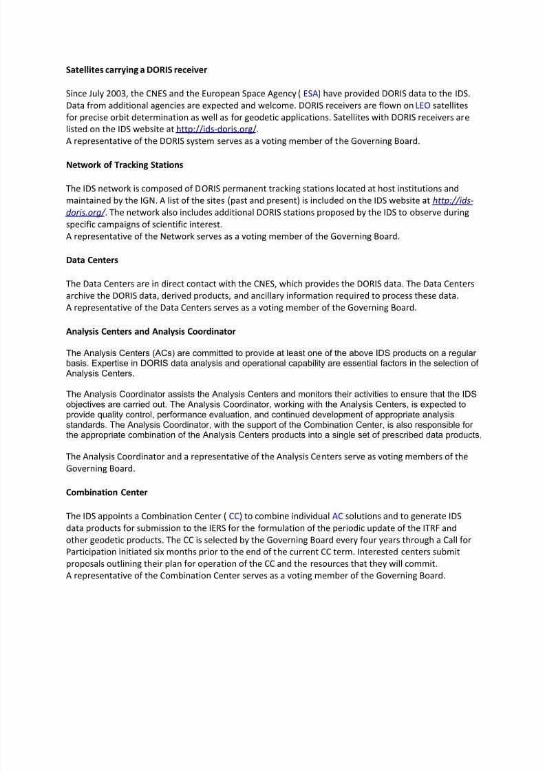
8112019 Tipos de oacuterbitasdocx
httpslidepdfcomreaderfulltipos-de-orbitasdocx 1730
Governing Board
The principal role of the Governing Board (GB) is to set policy and to exercise broad oversight of all IDS
functions and components It also controls general activities of the Service including restructuring
when appropriate to maintain Service efficiency and reliability
The Governing Board (GB) consists of eleven voting members and a number of non-voting membersThe membership is chosen to try to strike the right balance between project specialists and the generalcommunity The voting membership of the GB is distributed as follows
Elected by IDS Associates (see below)
Analysis Centers representative 1Data centers representative 1 Analysis Coordinator 1Members at large 2
Appointed members
Director of the Central Bureau 1IERS representative to IDS 1IAG representative to IDS 1Combination Center representative 1DORIS System representative (CNES)1Network representative (IGN) 1
Total number of voting members 11
During their mandate the Working Group chairpersons are GB members with voice but without vote
The elected members have staggered four-year terms with elections every two years
There is no limit to the number of terms that a person may serve however he or she may serve only twoterms consecutively as an elected member
The Analysis Centersrsquo representative the Data Centersrsquo representative and one Member -at-Large areelected during the first two-year election
The Analysis Coordinator and the other Member-at-Large are elected in the second two-year election
Although no formula is prescribed efforts should be made to keep the GB membership properly balancedwith regard to supporting organizations and geographic representation
Members of the GB become IAG Fellows with the appropriate rights and privileges as described on the
IAG website after an initial two-year period
GB elections
The GB elects a Chairperson from its members to serve a term of four years with the possibility of re-
election for one additional term The Chairperson does not vote on GB decisions except in the case of a
tie The Chairperson is the official representative of the IDS to external organizations
8112019 Tipos de oacuterbitasdocx
httpslidepdfcomreaderfulltipos-de-orbitasdocx 1830
Five members of the GB are elected by the IDS Associates A nominating committee conducts theelections for membership on the IDS Governing Board
The nominating committee consists of three members The Chair of the nominating committee isappointed by the Chair of the GB and must be a member of the GB not currently up for re-election TheGB chooses the remaining two members of the nominating committee from the list of IDS Associates Thenominating committee solicits nominations from the IDS Associates for each position to be filled at leasttwo candidates are required for each position
The Central Bureau runs the election
All IDS Associates are eligible to vote
Election is by a simple majority of votes received for each position
The two Member-at-Large positions are filled by the two candidates receiving the most votes a vote by
the GB will resolve any situation of a tie
Appointed Members
The IAG and IERS representatives to the IDS Governing Board are appointed respectively by the IAGExecutive Committee and by the IERS Directing Board for a maximum of two four-year terms
The DORIS System representative and the Network representative are appointed by CNES and IGNrespectively for four-year terms without limitation
The Director of the Central Bureau and the Combination Center representative are the two otherappointed members
In case of a resignation from the Governing Board the CB after consulting with the appropriate IDScomponents nominates a replacement candidate for election by the GB The replacement will serve untilthe end of the term of the resigned Board member
GB Decisions
Most decisions at GB meetings are to be made by consensus or by a simple majority vote of the voting
members present provided that there is a quorum consisting of at least six voting members of the GB
GB decisions can be made through email or other correspondence by a majority vote of the GB voting
membership Changes in the IDS Terms of Reference and Chairperson of the GB can only be made by a
23 majority of the members of the GB ie by seven or more votes
GB Meetings
The Board shall meet at least annually and at such other times as shall be considered appropriate by the
Chairperson or at the request of three members
The Central Bureau provides the secretariat of the GBIDS representatives to the IERS and the IAG
Through the existing reciprocity agreement between the IDS and the IERS the IDS Analysis Coordinator
serves as the DORIS Technique Center representative to IERS and as such subject to Governing Board
approval is a member of the IERS Directing Board (together with another person selected by the IDS
Governing Board) This arrangement ensures full cooperation between the two services
The IDS Governing Board will select the IDS representative to the IAG Executive Committee
8112019 Tipos de oacuterbitasdocx
httpslidepdfcomreaderfulltipos-de-orbitasdocx 1930
IDS Associates
IDS Associates are persons representing organizations that participate in any of the IDS components
A participating institution can submit a personrsquos name email and primary IDS function in its organizationto the Central Bureau for application to become an IDS Associate
The Governing Board approves all memberships
The Central Bureau maintains the current list of IDS Associates and makes the list available on the IDSwebsite
IDS Associates vote for the incoming Analysis Centersrsquo representative the Data Centersrsquo representativethe Analysis Coordinator and the Members-at-Large representatives as members of the GB
The GB must approve the list of IDS Associates eligible for voting in the elections at least three monthsprior to the election process
For the purposes of the election current and former GB members are also considered IDS Associates
IDS Associates are considered IAG Affiliates
After a decade of fully operational functioning the DORIS space geodesy system has demonstrated itscapabilities for orbitography and navigation of the satellites and also ground location It plays a key role inthe TopexPoseidon altimetric mission for oceanography providing in association with the Laser techniquea 2 cm accuracy in the radial component of the orbit DORIS and Laser are renewed as the nominalorbitographic system for the Jason mission (end of 2000)
DORIS also provides with Diode navigator on Spot 4 (1993) an orbit in real time within a few meters Itsa world first at this level of precision
Since 1994 and thanks to its more than fifty permanent beacon network DORIS contributes to
the IERS activities for the realization and maintenance of the ITRS (International Terrestrial ReferenceSystem) 3D positions and velocities of the reference sites at a cm and mmyr accuracy lead to scientificstudies (investigations) in the fields of global and regional tectonics Two recent DORIS results appearvery encouraging for the future One concerns a seasonal effect of earth surface fluid mass redistribution(oceanic water atmospheric masses snow ) on the relative positions of the earth mass and earthfigure centers Another concerns vertical displacement of the crust monitored near tides-gages Thisinformation is of major interest for the topic of sea level variations and correlation to the Global Change
Such as the other space geodesy techniques GPS VLBI SLR there is a strong demand among thescientific community to create an International DORIS Service so called IDS TheCSTG commission forinternational co-ordination of space techniques for geodesy of the International Association Geodesy( IAG) and the IERS directing board decided in July 1999 to initiate a DORIS Pilot Experiment Itsobjective was to assess the need and feasibility of an International DORIS Service
Since July1 2003 the International DORIS Service has been officially started as an IAGService after the decision of the IAG Executive Committtee at the IUGG General Assembly in SapporoNew terms of reference were released They describe the goals and organization of the IDS
8112019 Tipos de oacuterbitasdocx
httpslidepdfcomreaderfulltipos-de-orbitasdocx 2030
HOW ALTIMETRY WORKS
Altimetry satellites basically determine the distance from the satellite to a target surface by measuring
the satellite-to-surface round-trip time of a radar pulse However this is not the only measurement
made in the process and a lot of other information can be extracted from altimetry
The magnitude and shape of the echoes (or waveforms) also contain information about the
characteristics of the surface which caused the reflection The best results are obtained over the ocean
which is spatially homogeneous and has a surface which conforms with known statistics Surfaces which
are not homogeneous which contain discontinuities or significant slopes such as some ice rivers or
land surfaces make accurate interpretation more difficult
Basic principle
Radar altimeters permanently transmit signals to Earth and receive the echo from the surface The
satellite orbit have to be accurately tracked (Doris system) and its position is determined relative to an
arbitrary reference surface an ellipsoid The sea surface height (SSH) is the range from the sea surface
to a reference ellipsoid
8112019 Tipos de oacuterbitasdocx
httpslidepdfcomreaderfulltipos-de-orbitasdocx 2130
Pulses and waveforms
Altimetry satellites basically determine the distance from the satellite to a target surface by measuringthe satellite-to-surface round-trip time of a radar pulse The magnitude and shape of the echoes (orwaveforms) also contain information about the characteristics of the surface which caused thereflection
Frequencies used
Several different frequencies are used for radar altimeters Each frequency band has its advantagesand disadvantages sensitivity to atmospheric perturbations for Ku-band better observation of icerain coastal zones land masses for Ka-band
FUTURE TECHNOLOGY IMPROVEMENTS
Satellite altimetry has proven to be a valuable source of data for a broad range of applications Looking beyond the
missions in operational service today future satellites will need to provide better spatial and temporal coverage so
that we can study further near the coasts or mesoscale variations and other phenomena more closely For the
medium term consideration is now being given to altimetry missions capable of scanning the ocean surface to
acquire data at scales of a few tens of kilometres passing over the same spots every few days Other projects onthe drawing board are based on constellations of dedicated low-cost microsatellites The use of opportunity
signals is also being considered with the possibility of retrieving reflected signals transmitted by satellites in the
Global Navigation Satellite System (GNSS)
Altimeter-interferometers
An altimeterinterferometer would include several altimeters mounted on masts which would acquire
measurements simultaneously thus providing continuous single- or multi-altimeter wide-area
coverage ltbrgt Further information
Constellations
One of the ways to improve altimetry resolution is to use several satellites at the same time Until now this has
been done with very different types of satellite The use of several identical satellites in constellation could reduce
costs (development costs and launch costs too for micro-satellites launched by the same rocket)
GNSS altimetry
One approach being pursued to achieve maximum altimetry data coverage is to receive reflected signals
transmitted by satellites in the Global Navigation Satellite System (GNSS) in particular from the Global Positioning
System (GPS) constellation and its European civil counterpart Galileo This concept is based on a satellite in near-
polar orbit (at an altitude of 400 to 500 km) retrieving signals emitted by multiple satellites and reflected by the
ocean surface then analysing these signals to compute sea surface height This concept is currently still only in the
study phase
RADIOMETRY PRINCIPLE
Microwave remote sensing uses passive microwave radiometers The microwaves have wavelength ranging from a
few kHz to THz The ldquopassiverdquo term means that it uses microwaves naturally radiated by the observed area (this is
different from the radar principle where the sensor transmits a microwave signal towards a target and detects the
backscattered radiation)
Radiometry principle
8112019 Tipos de oacuterbitasdocx
httpslidepdfcomreaderfulltipos-de-orbitasdocx 2230
Radiometry principle
Satellite passive microwave radiometers measure raw antenna counts from which we determine the antenna
temperature and then calculate the brightness temperature of the Earth Large antennas are used for the various
channels of the radiometer and in operation each antenna feedhorn passes a hot and cold target in order toprovide consistently calibrated raw counts Brightness temperature is a measure of the radiance of microwave
radiation traveling upward from the top of Earths atmosphere The conversion from radiometer counts to top-of-
the-atmosphere (TOA) brightness temperature is called the calibration process Several calibration processing
steps are required to derive the brightness temperature values
Radiometry applications
Microwave radiometer brightness temperatures are considered as a fundamental climate data record
and are the values from which we derive ocean measurements of wind speed water vapor cloud liquid
water rain rate and sea surface temperature
Missions
The main passive microwave radiometers are listed below (instrumentsatellite)
AMSR-E on Aqua
SSMI on DMSP F08 F10 F11 F13 F14 F15
SSMIS on DMSP F16 F17
WindSat on Coriolis
TMI on TRMM
AMSR2 GCOM - W1
Radiometers and altimeters
In the altimetry domain interesting radiometers are those that are on-board altimetric missions such
as JMR MWR AMR Altika radiometer etc These microwave radiometers measure the total water
vapor along the path viewed by the altimeter In addition to measuring total water vapor they are used
for range correction and to measure brightness temperatures
8112019 Tipos de oacuterbitasdocx
httpslidepdfcomreaderfulltipos-de-orbitasdocx 2330
Using generally two (238 37 GHz for Altika radiometer on board SARAL) or three different frequencies
(eg 187 238 340GHz for the AMR on-board OSTMJason-2) measurements acquired at each
frequency are combined to determine atmospheric water vapor and liquid water content Once the
water content is known it is possible to determine the correction to be applied for radar signal path
delays
Altimetry missions that operate without radiometer (eg Cryosat-2) can use estimation of wet
tropospheric correction coming from atmospheric models
For more information
JMR instrument on-board Jason-1
AMR instrument on-board OSTMJason-2
MWR instrument on-board Envisat
AltiKa on-board SARAL
The International Laser Ranging Service (ILRS) provides global satellite and lunar laser ranging data and their related
products to support geodetic and geophysical research activities as well as IERS products important to the
maintenance of an accurate International Terrestrial Reference Frame (ITRF) The service develops the necessary
global standardsspecifications and encourages international adherence to its conventions The ILRS is one of the
space geodetic services of the International Association of Geodesy (IAG)
The ILRS collects merges archives and distributes Satellite Laser Ranging (SLR) and Lunar Laser Ranging (LLR)
observation data sets of sufficient accuracy to satisfy the objectives of a wide range of scientific engineering and
operational applications and experimentation These data sets are used by the ILRS to generate a number of
scientific and operational data products including
Earth orientation parameters (polar motion and length of day)
Station coordinates and velocities of the ILRS tracking systems
Time-varying geocenter coordinates
Static and time-varying coefficients of the Earths gravity field
Centimeter accuracy satellite ephemerides
Fundamental physical constants
Lunar ephemerides and librations
Lunar orientation parameters
The accuracy of SLRLLR data products is sufficient to support a variety of scientific and operational applications
including
Realization of global accessibility to and the improvement of the International Terrestrial Reference Frame
(ITRF)
Monitoring three dimensional deformations of the solid Earth
Monitoring Earth rotation and polar motion
8112019 Tipos de oacuterbitasdocx
httpslidepdfcomreaderfulltipos-de-orbitasdocx 2430
Support the monitoring of variations in the topography and volume of the liquid Earth (ocean circulation mean
sea level ice sheet thickness wave heights etc)
Tidally generated variations in atmospheric mass distribution
Calibration of microwave tracking techniques
Picosecond global time transfer experiments
Astrometric observations including determination of the dynamic equinox obliquity of the ecliptic and the
precession constant
Gravitational and general relativistic studies including Einsteins Equivalence Principle the Robertson-Walker b
parameter and time rate of change of the gravitational constant
Lunar physics including the dissipation of rotational energy shape of the core-mantle boundary (Love Number
k2) and free librations and stimulating mechanisms
Solar System ties to the International Celestial Reference Frame (ICRF)
Satellite Laser Ranging (SLR) and Lunar Laser Ranging (LLR) use short-pulse lasers and state-of-the-art opticalreceivers and timing electronics to measure the two-way time of flight (and hence distance) from ground stations toretroreflector arrays on Earth orbiting satellites and the Moon Scientific products derived using SLR and LLR datainclude precise geocentric positions and motions of ground stations satellite orbits components of Earthrsquos gravityfield and their temporal variations Earth Orientation Parameters (EOP) precise lunar ephemerides and informationabout the internal structure of the Moon Laser ranging systems are already measuring the one-way distance toremote optical receivers in space and can perform very accurate time transfer between sites far apart Laser rangingactivities are organized under the International Laser Ranging Service (ILRS) which provides global satellite andlunar laser ranging data and their derived data products to support research in geodesy geophysics Lunar scienceand fundamental constants This includes data products that are fundamental to the International TerrestrialReference Frame (ITRF) which is established and maintained by the International Earth Rotation and ReferenceSystems Service (IERS) The ILRS develops the necessary global standardsspecifications for laser ranging activitiesand encourages international adherence to its conventions
Analysis Products
The ILRS provides a service to utilize Satellite and Lunar Laser Ranging data to generate geodetic geodynamic andgeophysical scientific products
Currently five SLR analysis groups (ASI DGFI GFZ JCET and NSGF) provide direct input for the official ILRSproducts (stationcoordinates and Earth Orientation Parameters EOPs) The results of the ILRS POS+EOP pilot project wereevaluated during the AWG meeting in San Fernando The five contributors were acknowledged and given an officialstatus In addition ASI was selected as the official ILRS primary combination center and DGFI was selected as theofficial ILRS backup combination center each for a two-year term As well as the contributors of individual solutionsthese combination centers must follow strict timelines and provide routine products of the highest possible qualityWeekly official ILRS products from these two combination centers are now available in SINEX format eachWednesday at CDDIS and EDC Analysis centers will again compete for the ILRS combination and backup center in
mid-2006 at the International Laser Ranging Workshop in Australia All groups are encouraged to develop (thequality of) their contributions furtherThe ILRS now generates weekly unconstrained solutions for station coordinates (valid for the mid-point of each 7-day interval) and EOPs (x-pole y-pole and Length-Of-Day (LOD) all of them for 1-day intervals) These results arestored in subdirectories of the form pos+eopYYMMDD where YYMMDD is the date (YY =2 digit year MM =2 digitmonth and DD=2 digit day) of the end of each 7-day interval Within each subdirectory one finds so-called individualsolutions and combination solutions that are explained belowFor the individual contributions to the POS+EOPproject filenames are of the form (examples reflect CDDIS archive)ftpcddisgsfcnasagovpubslrproductspos+eopYYMMDDCENTER pos+eopYYMMDDv1snxZHere CENTER is replaced by the name of the actual contributor It is the first solution that is generated for thisperiod and by this analysis center hence v1 If re-computations are necessary the version number will be
8112019 Tipos de oacuterbitasdocx
httpslidepdfcomreaderfulltipos-de-orbitasdocx 2530
increased by one solutions for new weeks will start with v1 however The results are stored in the SINEX format(snx) The reader is refered to the COMMENTS section of each solution (in the file itself) or more generalexplanations of SINEX for further details of the solution andor the formatThe official ILRS primary product on POS+EOP is labeled as
ftpcddisgsfcnasagovpubslrproductspos+eopYYMMDDilrsapos+eopYYMMDDv1snxZIn a similar fashion the EOP solutions (wrt ITRF2000) generated by the official ILRS primary combination centerare named
ftpcddisgsfcnasagovpubslrproductspos+eopYYMMDDilrsaeopYYMMDDv1snxZThe ILRS also has an official backup combination center and its products are labeled
ftpcddisgsfcnasagovpubslrproductspos+eopYYMMDDilrsbpos+eopYYMMDDv1snxZftpcddisgsfcnasagovpubslrproductspos+eopYYMMDDilrsbeopYYMMDDv1snxZCurrently the ILRS AWG is in the process of computing similar solutions for the years before the workshop in SanFernando At this moment the AWG works on solutions going back to the launch date of LAGEOS-2 (ie November1992) It is foreseen that this will (at a later stage) be followed by computations for the time frame extending back toSeptember 1983 the beginning of the MERIT campaign
Historical products include
Earth Orientation Parameters (EOP)o GSFC 98L01 solution
o CSR 95L01 solutiono Delft University of Technology 92L01 solutiono GeoForschungsZentrum 95L01 solutiono Centro di Geodesia Spaziale solutions
Coordinates and velocities of the tracking stations
Geocenter coordinates - IERS Geocenter campaign results IERS TN25
In Satellite Laser Ranging a short pulse of coherent light generated by a laser (Light Amplification by Stimulated
Emission of Radiation) is transmitted in a narrow beam to illuminate corner cube retroreflectors on the satellite Thereturn signal typically a few photons is collected by a telescope and the time-of-flight is measured Using informationabout the satellitersquos orbit the time-of-flight and the speed of light the location of the ranging station can bedetermined Similar data acquired by another station many kilometers distant from the first or on a different continentcan be used to determine the distance between stations to precisions of centimeters or better Repetitivemeasurements over months and years yield the changein distance or the motion of the Earthrsquos crust
Laser ranging to a near-Earth satellite was initiated byNASA in 1964 with the launch of the Beacon-B satelliteSince that time ranging precision spurred by scientificrequirements has improved by a factor of a thousandfrom a few meters to a few millimeters Similarly thenetwork of laser stations has grown from a fewexperimental sites to a global network of 43 stations inmore than 30 countries Most of these stations (33) arefunded by organizations other than NASA
During the past three decades the global Satellite LaserRanging (SLR) network has evolved into a powerfulsource of data for studies of the solid Earth and itsocean and atmospheric systems including
Detection and monitoring of tectonic plate motioncrustal deformation Earth rotation and polar motion
Modeling of the spatial and temporal variations of the Earthrsquos gravitational field
Determination of basin-scale ocean tides
Monitoring of millimeter-level variations in the location of the center of mass of the total Earth system (solidEarth-atmosphere-oceans)
Establishment and maintenance of the International Terrestrial Reference System (ITRS) and
Detection and monitoring of post-glacial rebound and subsidence
8112019 Tipos de oacuterbitasdocx
httpslidepdfcomreaderfulltipos-de-orbitasdocx 2630
In addition SLR provides precise orbit determination for spaceborne radar altimeter missions mapping the oceansurface (which are used to model global ocean circulation) for mapping volumetric changes in continental ice massesand for land topography It provides a means for subnanosecond global time transfer and a basis for special tests ofthe Theory of General Relativity
SLR uses special passive spacecraft in very stable orbits A low area to mass ratio minimizes the effects ofatmospheric drag and solar radiation pressure on the satellitersquos orbit
An example of such a satellite is the Laser Geodynamics Satellite (LAGEOS-1) which was launched by the UnitedStates in 1976 into a 6000 kilometer circular orbit with a near polar inclination Lageos-I and its sister satelliteLageos-II (built by the Agenzia Spaziale Italiana of Italy and launched in 1992 into a 6000 kilometer orbit but with aninclination of 51 degrees) have a 60 centimeter spherical shape and weigh 411 kilograms The exterior surface ofboth satellites is covered by 426 retroreflectors
Other satellites for SLR include Starlette (1000 km) and Stella (800 km) developed and launched by France Etalon-Iand -2 (19000 km) developed and launched by the former USSR and Ajisai (1500 km) developed and launched byJapan To obtain data for precise orbit determination retroreflectors are also mounted on the USFranceTopexPoseidon spacecraft the European Space Agency Earth Remote Sensing satellites (ERS-1 and 2) and on afew of the United States Global Positioning System (GPS) satellites
Fixed and mobile SLR systems have been used to acquire data for studies of crustal deformation and plate motion atscales from several hundred kilometers to several thousand kilometers to monitor polar motion and Earth rotationand to model the Earthrsquos gravity field
Lunar Laser Ranging (LLR)
During three US American Apollo missions (11 14 and 15) and two unmanned Soviet missions (Luna 17 and Luna21) retro-reflectors were deployed near the lunar landing sites between 1969 and 1973 The Lunar Laser Ranging(LLR) experiment has continuously provided range data for about 41 years generating about 17000 normal pointsThe main benefit of this space geodetic technique is the determination of a host of parameters describing lunarephemeris lunar physics the Moons interior various reference frames Earth orientation parameters and the Earth-Moon dynamics LLR has also become one of the strongest tools for testing Einsteins theory of general relativity inthe solar system no violations of general relativity have been found so far However the basis for all scientificanalyses is more high quality data from a well-distributed global LLR network More information is provided onthe LLR page
SLR and LLR are used in the following scientific research
Atmosphere-Hydrosphere-Cryosphere-Solid Earth Interactions Long-Term Dynamics of the Solid Earth Oceans and Ice Fields
Tides
Sensing of surface elevations
Mantle
Lunar Science
About IVS
Overview of IVS
IVS is an international collaboration of organizations which operate or support Very Long Baseline Interferometry(VLB I) components
The objectives of IVS are
to provide a service to support geodetic geophysical and astrometric research and operational activities
to promote research and development activities in all aspects of the geodetic and astrometric VLBI technique and
to interact with the community of users of VLBI products and to integrate VLBI into a global Earth observing system
The service aspect of IVS is meant to serve both outside users and the geodetic and astrometric community itselfBoth the contributors and users of data will be served
8112019 Tipos de oacuterbitasdocx
httpslidepdfcomreaderfulltipos-de-orbitasdocx 2730
IVS provides data and products for the scientific community Some of the products are
a terrestrial reference frame (TRF)
the international celestial reference frame (ICRF) and
Earth orientation parameters (EOP)
All IVS data and products are archived in data centers and are publically available for research in relatedareas of geodesy geophysics and astrometry
General The IVS observing program consists of various series of 24-hour observing sessions The
program is planned by the Observing Program Committee coordinated by the IVS Coordinating Center and
executed by the Network Stations Operation Centers andCorrelators The result of the observing program is
the data held in the Data Centers that is then available for analysis The flow of data and the resulting
products are shown graphically on the IVS structure and flow diagram Auxiliary data files such as schedule
and notes files are used to facilitate the observing operations They can be accessed from the IVS
Datapage or following procedures outlined in the Download Schedules page
IVS Live Following the success of the dynamic Web site for the IYA09 session Laboratoire
dAstrophysique de Bordeaux developed a generalized version of this tool for the entire IVS observingplan The resulting IVS Live site allows the user to monitor each session in real-time in terms of stations
scans and sources being used It provides links to Webcams and further ancillary information Follow
the countdown to the next IVS session or check out past or future IVS sessions using the session
calendar Many thanks to Arnaud Collioud and Bordeaux Observatory for making this possible
IVS Network Stations acquire geodetic and astrometric VLBI data Data acquisition at Network Stations is
controlled by schedules prepared by Operation Centers The raw data and log files are transmitted to
the Correlators for processing Details of the planned sessions are published in the Master Files maintained
by the Coordinating Center
About the IGS
The IGS global system of satellite tracking stations Data Centers and Analysis
Centers puts high-quality GPS data and data products on line in near real time to
meet the objectives of a wide range of scientific and engineering applications and
studies
The IGS collects archives and distributes GPS observation data sets of sufficientaccuracy to satisfy the objectives of a wide range of applications and experimentationThese data sets are used by the IGS to generate the data products mentioned abovewhich are made available to interested users through the Internet In particular theaccuracies of IGS products are sufficient for the improvement and extension of theInternational Terrestrial Reference Frame (ITRF) the monitoring of solid Earthdeformations the monitoring of Earth rotation and variations in the liquid Earth (sealevel ice-sheets etc) for scientific satellite orbit determinations ionospheremonitoring and recovery of precipitable water vapor measurements
8112019 Tipos de oacuterbitasdocx
httpslidepdfcomreaderfulltipos-de-orbitasdocx 2830
Mission
The primary mission of the International GPS Service as stated in the organizations
2002-2007 Strategic Plan is
The International GPS Service is committed to providing the highest quality data
and products as the standard for global navigation satellite systems (GNSS) in
support of Earth science research multidisciplinary applications and education
These activities aim to advance scientific understanding of the Earth system
components and their interactions as well as to facilitate other applications
benefiting society
The IGS Terms of Reference (comparable to the by-laws of the organization)describes in broad terms the goals and organization of the IGS
To accomplish its mission the IGS has a number of components an internationalnetwork of over 350 continuously operating dual-frequency GPS stations more than adozen regional and operational data centers three global data centers seven analysiscenters and a number of associate or regional analysis centers The Central Bureau forthe service is located at the Jet Propulsion Laboratory which maintains the CentralBureau Information System (CBIS) and ensures access to IGS products andinformation An international Governing Board oversees all aspects of the IGS TheIGS is an approved service of the International Association of Geodesy since 1994and is recognized as a member of the Federation of Astronomical and Geophysical
Data Analysis Services (FAGS) since 1996
For more information concerning IGS organization click here
History
Since the late 1980s the US Global Positioning System (GPS) constellation ofsatellites has come to play a major role in regional and global studies of Earth In theface of continued growth and diversification of GPS applications the worldwidescientific community has made an effort to promote international standards for GPS
data acquisition and analysis and to deploy and operate a common comprehensiveglobal tracking system
As part of this effort the IGS was formally recognized in 1993 by the InternationalAssociation of Geodesy (IAG) and began routine operations on January 1 1994 providing GPS orbits tracking data and other data products in support of geodeticand geophysical research In particular since January 1994 the IGS has madeavailable to its user community the IGS official orbit based on contributions from the
8112019 Tipos de oacuterbitasdocx
httpslidepdfcomreaderfulltipos-de-orbitasdocx 2930
seven current IGS Analysis Centers The IGS also supports a variety of governmentaland commercial activities and develops international GPS data standards andspecifications A description of the development and evolution of the IGS can befound in a number of publications with detailed documentation contained in the IGSAnnual Report Series published by the IGS Central Bureau via the World Wide WebThis series contains the yearly contributions from all components of service anddemonstrates that the key to success of the IGS has been the broad support of theinternational geodynamics and geodetic communities and their sponsoringorganizations This Information System is sponsored by the National Aeronautic andSpace Administration ( NASA) and managed for NASA by the Jet PropulsionLaboratory (JPL) of the California Institute of Technology (Caltech)
Operations
The IGS has developed a worldwide system comprising satellite tracking stations
Data Centers and Analysis Centers to put high-quality GPS data and data productson line within a day of observations For example following the NorthridgeCalifornia earthquake in January 1994 analysis teams using IGS-supplied data and products were able to quickly evaluate the disasters immediate effects by determiningstation displacements accurately to within a few millimeters
The IGS global network of permanent tracking stations each equipped with a GPSreceiver generates raw orbit and tracking data The Operational Data Centers whichare in direct contact with the tracking sites collect the raw receiver data and formatthem according to a common standard using a data format called Receiver
Independent Exchange (RINEX) The formatted data are then forwarded to theRegional or Global Data Centers To reduce electronic network traffic the RegionalData Centers are used to collect data from several Operational Data Centers beforetransmitting them to the Global Data Centers Data not used for global analyses arearchived and available for online access at the Regional Data Centers The GlobalData Centers archive and provide on-line access to tracking data and data products
Products and Applications
The IGS collects archives and distributes GPS observation data sets of sufficient
accuracy to meet the objectives of a wide range of scientific and engineeringapplications and studies These data sets are used to generate the following products
GPS satellite ephemerides
GLONASS satellite ephemerides
Earth rotation parameters
IGS tracking station coordinates and velocities
8112019 Tipos de oacuterbitasdocx
httpslidepdfcomreaderfulltipos-de-orbitasdocx 3030
GPS satellite and IGS tracking station clock information
Zenith tropospheric path delay estimates
Global ionospheric maps
IGS products support scientific activities such as improving and extending theInternational Earth Rotation Service (IERS) Terrestrial Reference Frame (ITRF)monitoring deformations of the solid Earth and variations in the liquid Earth (sea levelice sheets etc) and in Earth rotation determining orbits of scientific satellites andmonitoring the ionosphere For example geodynamics investigators who use GPS inlocal regions can include data from one or more nearby IGS stations fix the sitecoordinates from such stations to their ITRF values and more importantly use the precise IGS orbits without further refinement Data from an investigators localnetwork can then be analyzed with maximum accuracy and minimum computational burden Furthermore the results will be in a well-defined global reference frame
An additional aspect of IGS products is for the densification of the ITRF at a moreregional level This is accomplished through the rigorous combination of regional orlocal network solutions utilizing the Solution Independent Exchange Format (SINEX) and a process defined in the densification section
In the future the IGS infrastructure could become a valuable asset for support of newground-based applications and could also contribute to space-based missions inwhich highly accurate flight and ground differential techniques are required
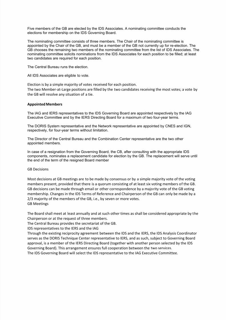
8112019 Tipos de oacuterbitasdocx
httpslidepdfcomreaderfulltipos-de-orbitasdocx 1930
IDS Associates
IDS Associates are persons representing organizations that participate in any of the IDS components
A participating institution can submit a personrsquos name email and primary IDS function in its organizationto the Central Bureau for application to become an IDS Associate
The Governing Board approves all memberships
The Central Bureau maintains the current list of IDS Associates and makes the list available on the IDSwebsite
IDS Associates vote for the incoming Analysis Centersrsquo representative the Data Centersrsquo representativethe Analysis Coordinator and the Members-at-Large representatives as members of the GB
The GB must approve the list of IDS Associates eligible for voting in the elections at least three monthsprior to the election process
For the purposes of the election current and former GB members are also considered IDS Associates
IDS Associates are considered IAG Affiliates
After a decade of fully operational functioning the DORIS space geodesy system has demonstrated itscapabilities for orbitography and navigation of the satellites and also ground location It plays a key role inthe TopexPoseidon altimetric mission for oceanography providing in association with the Laser techniquea 2 cm accuracy in the radial component of the orbit DORIS and Laser are renewed as the nominalorbitographic system for the Jason mission (end of 2000)
DORIS also provides with Diode navigator on Spot 4 (1993) an orbit in real time within a few meters Itsa world first at this level of precision
Since 1994 and thanks to its more than fifty permanent beacon network DORIS contributes to
the IERS activities for the realization and maintenance of the ITRS (International Terrestrial ReferenceSystem) 3D positions and velocities of the reference sites at a cm and mmyr accuracy lead to scientificstudies (investigations) in the fields of global and regional tectonics Two recent DORIS results appearvery encouraging for the future One concerns a seasonal effect of earth surface fluid mass redistribution(oceanic water atmospheric masses snow ) on the relative positions of the earth mass and earthfigure centers Another concerns vertical displacement of the crust monitored near tides-gages Thisinformation is of major interest for the topic of sea level variations and correlation to the Global Change
Such as the other space geodesy techniques GPS VLBI SLR there is a strong demand among thescientific community to create an International DORIS Service so called IDS TheCSTG commission forinternational co-ordination of space techniques for geodesy of the International Association Geodesy( IAG) and the IERS directing board decided in July 1999 to initiate a DORIS Pilot Experiment Itsobjective was to assess the need and feasibility of an International DORIS Service
Since July1 2003 the International DORIS Service has been officially started as an IAGService after the decision of the IAG Executive Committtee at the IUGG General Assembly in SapporoNew terms of reference were released They describe the goals and organization of the IDS
8112019 Tipos de oacuterbitasdocx
httpslidepdfcomreaderfulltipos-de-orbitasdocx 2030
HOW ALTIMETRY WORKS
Altimetry satellites basically determine the distance from the satellite to a target surface by measuring
the satellite-to-surface round-trip time of a radar pulse However this is not the only measurement
made in the process and a lot of other information can be extracted from altimetry
The magnitude and shape of the echoes (or waveforms) also contain information about the
characteristics of the surface which caused the reflection The best results are obtained over the ocean
which is spatially homogeneous and has a surface which conforms with known statistics Surfaces which
are not homogeneous which contain discontinuities or significant slopes such as some ice rivers or
land surfaces make accurate interpretation more difficult
Basic principle
Radar altimeters permanently transmit signals to Earth and receive the echo from the surface The
satellite orbit have to be accurately tracked (Doris system) and its position is determined relative to an
arbitrary reference surface an ellipsoid The sea surface height (SSH) is the range from the sea surface
to a reference ellipsoid
8112019 Tipos de oacuterbitasdocx
httpslidepdfcomreaderfulltipos-de-orbitasdocx 2130
Pulses and waveforms
Altimetry satellites basically determine the distance from the satellite to a target surface by measuringthe satellite-to-surface round-trip time of a radar pulse The magnitude and shape of the echoes (orwaveforms) also contain information about the characteristics of the surface which caused thereflection
Frequencies used
Several different frequencies are used for radar altimeters Each frequency band has its advantagesand disadvantages sensitivity to atmospheric perturbations for Ku-band better observation of icerain coastal zones land masses for Ka-band
FUTURE TECHNOLOGY IMPROVEMENTS
Satellite altimetry has proven to be a valuable source of data for a broad range of applications Looking beyond the
missions in operational service today future satellites will need to provide better spatial and temporal coverage so
that we can study further near the coasts or mesoscale variations and other phenomena more closely For the
medium term consideration is now being given to altimetry missions capable of scanning the ocean surface to
acquire data at scales of a few tens of kilometres passing over the same spots every few days Other projects onthe drawing board are based on constellations of dedicated low-cost microsatellites The use of opportunity
signals is also being considered with the possibility of retrieving reflected signals transmitted by satellites in the
Global Navigation Satellite System (GNSS)
Altimeter-interferometers
An altimeterinterferometer would include several altimeters mounted on masts which would acquire
measurements simultaneously thus providing continuous single- or multi-altimeter wide-area
coverage ltbrgt Further information
Constellations
One of the ways to improve altimetry resolution is to use several satellites at the same time Until now this has
been done with very different types of satellite The use of several identical satellites in constellation could reduce
costs (development costs and launch costs too for micro-satellites launched by the same rocket)
GNSS altimetry
One approach being pursued to achieve maximum altimetry data coverage is to receive reflected signals
transmitted by satellites in the Global Navigation Satellite System (GNSS) in particular from the Global Positioning
System (GPS) constellation and its European civil counterpart Galileo This concept is based on a satellite in near-
polar orbit (at an altitude of 400 to 500 km) retrieving signals emitted by multiple satellites and reflected by the
ocean surface then analysing these signals to compute sea surface height This concept is currently still only in the
study phase
RADIOMETRY PRINCIPLE
Microwave remote sensing uses passive microwave radiometers The microwaves have wavelength ranging from a
few kHz to THz The ldquopassiverdquo term means that it uses microwaves naturally radiated by the observed area (this is
different from the radar principle where the sensor transmits a microwave signal towards a target and detects the
backscattered radiation)
Radiometry principle
8112019 Tipos de oacuterbitasdocx
httpslidepdfcomreaderfulltipos-de-orbitasdocx 2230
Radiometry principle
Satellite passive microwave radiometers measure raw antenna counts from which we determine the antenna
temperature and then calculate the brightness temperature of the Earth Large antennas are used for the various
channels of the radiometer and in operation each antenna feedhorn passes a hot and cold target in order toprovide consistently calibrated raw counts Brightness temperature is a measure of the radiance of microwave
radiation traveling upward from the top of Earths atmosphere The conversion from radiometer counts to top-of-
the-atmosphere (TOA) brightness temperature is called the calibration process Several calibration processing
steps are required to derive the brightness temperature values
Radiometry applications
Microwave radiometer brightness temperatures are considered as a fundamental climate data record
and are the values from which we derive ocean measurements of wind speed water vapor cloud liquid
water rain rate and sea surface temperature
Missions
The main passive microwave radiometers are listed below (instrumentsatellite)
AMSR-E on Aqua
SSMI on DMSP F08 F10 F11 F13 F14 F15
SSMIS on DMSP F16 F17
WindSat on Coriolis
TMI on TRMM
AMSR2 GCOM - W1
Radiometers and altimeters
In the altimetry domain interesting radiometers are those that are on-board altimetric missions such
as JMR MWR AMR Altika radiometer etc These microwave radiometers measure the total water
vapor along the path viewed by the altimeter In addition to measuring total water vapor they are used
for range correction and to measure brightness temperatures
8112019 Tipos de oacuterbitasdocx
httpslidepdfcomreaderfulltipos-de-orbitasdocx 2330
Using generally two (238 37 GHz for Altika radiometer on board SARAL) or three different frequencies
(eg 187 238 340GHz for the AMR on-board OSTMJason-2) measurements acquired at each
frequency are combined to determine atmospheric water vapor and liquid water content Once the
water content is known it is possible to determine the correction to be applied for radar signal path
delays
Altimetry missions that operate without radiometer (eg Cryosat-2) can use estimation of wet
tropospheric correction coming from atmospheric models
For more information
JMR instrument on-board Jason-1
AMR instrument on-board OSTMJason-2
MWR instrument on-board Envisat
AltiKa on-board SARAL
The International Laser Ranging Service (ILRS) provides global satellite and lunar laser ranging data and their related
products to support geodetic and geophysical research activities as well as IERS products important to the
maintenance of an accurate International Terrestrial Reference Frame (ITRF) The service develops the necessary
global standardsspecifications and encourages international adherence to its conventions The ILRS is one of the
space geodetic services of the International Association of Geodesy (IAG)
The ILRS collects merges archives and distributes Satellite Laser Ranging (SLR) and Lunar Laser Ranging (LLR)
observation data sets of sufficient accuracy to satisfy the objectives of a wide range of scientific engineering and
operational applications and experimentation These data sets are used by the ILRS to generate a number of
scientific and operational data products including
Earth orientation parameters (polar motion and length of day)
Station coordinates and velocities of the ILRS tracking systems
Time-varying geocenter coordinates
Static and time-varying coefficients of the Earths gravity field
Centimeter accuracy satellite ephemerides
Fundamental physical constants
Lunar ephemerides and librations
Lunar orientation parameters
The accuracy of SLRLLR data products is sufficient to support a variety of scientific and operational applications
including
Realization of global accessibility to and the improvement of the International Terrestrial Reference Frame
(ITRF)
Monitoring three dimensional deformations of the solid Earth
Monitoring Earth rotation and polar motion
8112019 Tipos de oacuterbitasdocx
httpslidepdfcomreaderfulltipos-de-orbitasdocx 2430
Support the monitoring of variations in the topography and volume of the liquid Earth (ocean circulation mean
sea level ice sheet thickness wave heights etc)
Tidally generated variations in atmospheric mass distribution
Calibration of microwave tracking techniques
Picosecond global time transfer experiments
Astrometric observations including determination of the dynamic equinox obliquity of the ecliptic and the
precession constant
Gravitational and general relativistic studies including Einsteins Equivalence Principle the Robertson-Walker b
parameter and time rate of change of the gravitational constant
Lunar physics including the dissipation of rotational energy shape of the core-mantle boundary (Love Number
k2) and free librations and stimulating mechanisms
Solar System ties to the International Celestial Reference Frame (ICRF)
Satellite Laser Ranging (SLR) and Lunar Laser Ranging (LLR) use short-pulse lasers and state-of-the-art opticalreceivers and timing electronics to measure the two-way time of flight (and hence distance) from ground stations toretroreflector arrays on Earth orbiting satellites and the Moon Scientific products derived using SLR and LLR datainclude precise geocentric positions and motions of ground stations satellite orbits components of Earthrsquos gravityfield and their temporal variations Earth Orientation Parameters (EOP) precise lunar ephemerides and informationabout the internal structure of the Moon Laser ranging systems are already measuring the one-way distance toremote optical receivers in space and can perform very accurate time transfer between sites far apart Laser rangingactivities are organized under the International Laser Ranging Service (ILRS) which provides global satellite andlunar laser ranging data and their derived data products to support research in geodesy geophysics Lunar scienceand fundamental constants This includes data products that are fundamental to the International TerrestrialReference Frame (ITRF) which is established and maintained by the International Earth Rotation and ReferenceSystems Service (IERS) The ILRS develops the necessary global standardsspecifications for laser ranging activitiesand encourages international adherence to its conventions
Analysis Products
The ILRS provides a service to utilize Satellite and Lunar Laser Ranging data to generate geodetic geodynamic andgeophysical scientific products
Currently five SLR analysis groups (ASI DGFI GFZ JCET and NSGF) provide direct input for the official ILRSproducts (stationcoordinates and Earth Orientation Parameters EOPs) The results of the ILRS POS+EOP pilot project wereevaluated during the AWG meeting in San Fernando The five contributors were acknowledged and given an officialstatus In addition ASI was selected as the official ILRS primary combination center and DGFI was selected as theofficial ILRS backup combination center each for a two-year term As well as the contributors of individual solutionsthese combination centers must follow strict timelines and provide routine products of the highest possible qualityWeekly official ILRS products from these two combination centers are now available in SINEX format eachWednesday at CDDIS and EDC Analysis centers will again compete for the ILRS combination and backup center in
mid-2006 at the International Laser Ranging Workshop in Australia All groups are encouraged to develop (thequality of) their contributions furtherThe ILRS now generates weekly unconstrained solutions for station coordinates (valid for the mid-point of each 7-day interval) and EOPs (x-pole y-pole and Length-Of-Day (LOD) all of them for 1-day intervals) These results arestored in subdirectories of the form pos+eopYYMMDD where YYMMDD is the date (YY =2 digit year MM =2 digitmonth and DD=2 digit day) of the end of each 7-day interval Within each subdirectory one finds so-called individualsolutions and combination solutions that are explained belowFor the individual contributions to the POS+EOPproject filenames are of the form (examples reflect CDDIS archive)ftpcddisgsfcnasagovpubslrproductspos+eopYYMMDDCENTER pos+eopYYMMDDv1snxZHere CENTER is replaced by the name of the actual contributor It is the first solution that is generated for thisperiod and by this analysis center hence v1 If re-computations are necessary the version number will be
8112019 Tipos de oacuterbitasdocx
httpslidepdfcomreaderfulltipos-de-orbitasdocx 2530
increased by one solutions for new weeks will start with v1 however The results are stored in the SINEX format(snx) The reader is refered to the COMMENTS section of each solution (in the file itself) or more generalexplanations of SINEX for further details of the solution andor the formatThe official ILRS primary product on POS+EOP is labeled as
ftpcddisgsfcnasagovpubslrproductspos+eopYYMMDDilrsapos+eopYYMMDDv1snxZIn a similar fashion the EOP solutions (wrt ITRF2000) generated by the official ILRS primary combination centerare named
ftpcddisgsfcnasagovpubslrproductspos+eopYYMMDDilrsaeopYYMMDDv1snxZThe ILRS also has an official backup combination center and its products are labeled
ftpcddisgsfcnasagovpubslrproductspos+eopYYMMDDilrsbpos+eopYYMMDDv1snxZftpcddisgsfcnasagovpubslrproductspos+eopYYMMDDilrsbeopYYMMDDv1snxZCurrently the ILRS AWG is in the process of computing similar solutions for the years before the workshop in SanFernando At this moment the AWG works on solutions going back to the launch date of LAGEOS-2 (ie November1992) It is foreseen that this will (at a later stage) be followed by computations for the time frame extending back toSeptember 1983 the beginning of the MERIT campaign
Historical products include
Earth Orientation Parameters (EOP)o GSFC 98L01 solution
o CSR 95L01 solutiono Delft University of Technology 92L01 solutiono GeoForschungsZentrum 95L01 solutiono Centro di Geodesia Spaziale solutions
Coordinates and velocities of the tracking stations
Geocenter coordinates - IERS Geocenter campaign results IERS TN25
In Satellite Laser Ranging a short pulse of coherent light generated by a laser (Light Amplification by Stimulated
Emission of Radiation) is transmitted in a narrow beam to illuminate corner cube retroreflectors on the satellite Thereturn signal typically a few photons is collected by a telescope and the time-of-flight is measured Using informationabout the satellitersquos orbit the time-of-flight and the speed of light the location of the ranging station can bedetermined Similar data acquired by another station many kilometers distant from the first or on a different continentcan be used to determine the distance between stations to precisions of centimeters or better Repetitivemeasurements over months and years yield the changein distance or the motion of the Earthrsquos crust
Laser ranging to a near-Earth satellite was initiated byNASA in 1964 with the launch of the Beacon-B satelliteSince that time ranging precision spurred by scientificrequirements has improved by a factor of a thousandfrom a few meters to a few millimeters Similarly thenetwork of laser stations has grown from a fewexperimental sites to a global network of 43 stations inmore than 30 countries Most of these stations (33) arefunded by organizations other than NASA
During the past three decades the global Satellite LaserRanging (SLR) network has evolved into a powerfulsource of data for studies of the solid Earth and itsocean and atmospheric systems including
Detection and monitoring of tectonic plate motioncrustal deformation Earth rotation and polar motion
Modeling of the spatial and temporal variations of the Earthrsquos gravitational field
Determination of basin-scale ocean tides
Monitoring of millimeter-level variations in the location of the center of mass of the total Earth system (solidEarth-atmosphere-oceans)
Establishment and maintenance of the International Terrestrial Reference System (ITRS) and
Detection and monitoring of post-glacial rebound and subsidence
8112019 Tipos de oacuterbitasdocx
httpslidepdfcomreaderfulltipos-de-orbitasdocx 2630
In addition SLR provides precise orbit determination for spaceborne radar altimeter missions mapping the oceansurface (which are used to model global ocean circulation) for mapping volumetric changes in continental ice massesand for land topography It provides a means for subnanosecond global time transfer and a basis for special tests ofthe Theory of General Relativity
SLR uses special passive spacecraft in very stable orbits A low area to mass ratio minimizes the effects ofatmospheric drag and solar radiation pressure on the satellitersquos orbit
An example of such a satellite is the Laser Geodynamics Satellite (LAGEOS-1) which was launched by the UnitedStates in 1976 into a 6000 kilometer circular orbit with a near polar inclination Lageos-I and its sister satelliteLageos-II (built by the Agenzia Spaziale Italiana of Italy and launched in 1992 into a 6000 kilometer orbit but with aninclination of 51 degrees) have a 60 centimeter spherical shape and weigh 411 kilograms The exterior surface ofboth satellites is covered by 426 retroreflectors
Other satellites for SLR include Starlette (1000 km) and Stella (800 km) developed and launched by France Etalon-Iand -2 (19000 km) developed and launched by the former USSR and Ajisai (1500 km) developed and launched byJapan To obtain data for precise orbit determination retroreflectors are also mounted on the USFranceTopexPoseidon spacecraft the European Space Agency Earth Remote Sensing satellites (ERS-1 and 2) and on afew of the United States Global Positioning System (GPS) satellites
Fixed and mobile SLR systems have been used to acquire data for studies of crustal deformation and plate motion atscales from several hundred kilometers to several thousand kilometers to monitor polar motion and Earth rotationand to model the Earthrsquos gravity field
Lunar Laser Ranging (LLR)
During three US American Apollo missions (11 14 and 15) and two unmanned Soviet missions (Luna 17 and Luna21) retro-reflectors were deployed near the lunar landing sites between 1969 and 1973 The Lunar Laser Ranging(LLR) experiment has continuously provided range data for about 41 years generating about 17000 normal pointsThe main benefit of this space geodetic technique is the determination of a host of parameters describing lunarephemeris lunar physics the Moons interior various reference frames Earth orientation parameters and the Earth-Moon dynamics LLR has also become one of the strongest tools for testing Einsteins theory of general relativity inthe solar system no violations of general relativity have been found so far However the basis for all scientificanalyses is more high quality data from a well-distributed global LLR network More information is provided onthe LLR page
SLR and LLR are used in the following scientific research
Atmosphere-Hydrosphere-Cryosphere-Solid Earth Interactions Long-Term Dynamics of the Solid Earth Oceans and Ice Fields
Tides
Sensing of surface elevations
Mantle
Lunar Science
About IVS
Overview of IVS
IVS is an international collaboration of organizations which operate or support Very Long Baseline Interferometry(VLB I) components
The objectives of IVS are
to provide a service to support geodetic geophysical and astrometric research and operational activities
to promote research and development activities in all aspects of the geodetic and astrometric VLBI technique and
to interact with the community of users of VLBI products and to integrate VLBI into a global Earth observing system
The service aspect of IVS is meant to serve both outside users and the geodetic and astrometric community itselfBoth the contributors and users of data will be served
8112019 Tipos de oacuterbitasdocx
httpslidepdfcomreaderfulltipos-de-orbitasdocx 2730
IVS provides data and products for the scientific community Some of the products are
a terrestrial reference frame (TRF)
the international celestial reference frame (ICRF) and
Earth orientation parameters (EOP)
All IVS data and products are archived in data centers and are publically available for research in relatedareas of geodesy geophysics and astrometry
General The IVS observing program consists of various series of 24-hour observing sessions The
program is planned by the Observing Program Committee coordinated by the IVS Coordinating Center and
executed by the Network Stations Operation Centers andCorrelators The result of the observing program is
the data held in the Data Centers that is then available for analysis The flow of data and the resulting
products are shown graphically on the IVS structure and flow diagram Auxiliary data files such as schedule
and notes files are used to facilitate the observing operations They can be accessed from the IVS
Datapage or following procedures outlined in the Download Schedules page
IVS Live Following the success of the dynamic Web site for the IYA09 session Laboratoire
dAstrophysique de Bordeaux developed a generalized version of this tool for the entire IVS observingplan The resulting IVS Live site allows the user to monitor each session in real-time in terms of stations
scans and sources being used It provides links to Webcams and further ancillary information Follow
the countdown to the next IVS session or check out past or future IVS sessions using the session
calendar Many thanks to Arnaud Collioud and Bordeaux Observatory for making this possible
IVS Network Stations acquire geodetic and astrometric VLBI data Data acquisition at Network Stations is
controlled by schedules prepared by Operation Centers The raw data and log files are transmitted to
the Correlators for processing Details of the planned sessions are published in the Master Files maintained
by the Coordinating Center
About the IGS
The IGS global system of satellite tracking stations Data Centers and Analysis
Centers puts high-quality GPS data and data products on line in near real time to
meet the objectives of a wide range of scientific and engineering applications and
studies
The IGS collects archives and distributes GPS observation data sets of sufficientaccuracy to satisfy the objectives of a wide range of applications and experimentationThese data sets are used by the IGS to generate the data products mentioned abovewhich are made available to interested users through the Internet In particular theaccuracies of IGS products are sufficient for the improvement and extension of theInternational Terrestrial Reference Frame (ITRF) the monitoring of solid Earthdeformations the monitoring of Earth rotation and variations in the liquid Earth (sealevel ice-sheets etc) for scientific satellite orbit determinations ionospheremonitoring and recovery of precipitable water vapor measurements
8112019 Tipos de oacuterbitasdocx
httpslidepdfcomreaderfulltipos-de-orbitasdocx 2830
Mission
The primary mission of the International GPS Service as stated in the organizations
2002-2007 Strategic Plan is
The International GPS Service is committed to providing the highest quality data
and products as the standard for global navigation satellite systems (GNSS) in
support of Earth science research multidisciplinary applications and education
These activities aim to advance scientific understanding of the Earth system
components and their interactions as well as to facilitate other applications
benefiting society
The IGS Terms of Reference (comparable to the by-laws of the organization)describes in broad terms the goals and organization of the IGS
To accomplish its mission the IGS has a number of components an internationalnetwork of over 350 continuously operating dual-frequency GPS stations more than adozen regional and operational data centers three global data centers seven analysiscenters and a number of associate or regional analysis centers The Central Bureau forthe service is located at the Jet Propulsion Laboratory which maintains the CentralBureau Information System (CBIS) and ensures access to IGS products andinformation An international Governing Board oversees all aspects of the IGS TheIGS is an approved service of the International Association of Geodesy since 1994and is recognized as a member of the Federation of Astronomical and Geophysical
Data Analysis Services (FAGS) since 1996
For more information concerning IGS organization click here
History
Since the late 1980s the US Global Positioning System (GPS) constellation ofsatellites has come to play a major role in regional and global studies of Earth In theface of continued growth and diversification of GPS applications the worldwidescientific community has made an effort to promote international standards for GPS
data acquisition and analysis and to deploy and operate a common comprehensiveglobal tracking system
As part of this effort the IGS was formally recognized in 1993 by the InternationalAssociation of Geodesy (IAG) and began routine operations on January 1 1994 providing GPS orbits tracking data and other data products in support of geodeticand geophysical research In particular since January 1994 the IGS has madeavailable to its user community the IGS official orbit based on contributions from the
8112019 Tipos de oacuterbitasdocx
httpslidepdfcomreaderfulltipos-de-orbitasdocx 2930
seven current IGS Analysis Centers The IGS also supports a variety of governmentaland commercial activities and develops international GPS data standards andspecifications A description of the development and evolution of the IGS can befound in a number of publications with detailed documentation contained in the IGSAnnual Report Series published by the IGS Central Bureau via the World Wide WebThis series contains the yearly contributions from all components of service anddemonstrates that the key to success of the IGS has been the broad support of theinternational geodynamics and geodetic communities and their sponsoringorganizations This Information System is sponsored by the National Aeronautic andSpace Administration ( NASA) and managed for NASA by the Jet PropulsionLaboratory (JPL) of the California Institute of Technology (Caltech)
Operations
The IGS has developed a worldwide system comprising satellite tracking stations
Data Centers and Analysis Centers to put high-quality GPS data and data productson line within a day of observations For example following the NorthridgeCalifornia earthquake in January 1994 analysis teams using IGS-supplied data and products were able to quickly evaluate the disasters immediate effects by determiningstation displacements accurately to within a few millimeters
The IGS global network of permanent tracking stations each equipped with a GPSreceiver generates raw orbit and tracking data The Operational Data Centers whichare in direct contact with the tracking sites collect the raw receiver data and formatthem according to a common standard using a data format called Receiver
Independent Exchange (RINEX) The formatted data are then forwarded to theRegional or Global Data Centers To reduce electronic network traffic the RegionalData Centers are used to collect data from several Operational Data Centers beforetransmitting them to the Global Data Centers Data not used for global analyses arearchived and available for online access at the Regional Data Centers The GlobalData Centers archive and provide on-line access to tracking data and data products
Products and Applications
The IGS collects archives and distributes GPS observation data sets of sufficient
accuracy to meet the objectives of a wide range of scientific and engineeringapplications and studies These data sets are used to generate the following products
GPS satellite ephemerides
GLONASS satellite ephemerides
Earth rotation parameters
IGS tracking station coordinates and velocities
8112019 Tipos de oacuterbitasdocx
httpslidepdfcomreaderfulltipos-de-orbitasdocx 3030
GPS satellite and IGS tracking station clock information
Zenith tropospheric path delay estimates
Global ionospheric maps
IGS products support scientific activities such as improving and extending theInternational Earth Rotation Service (IERS) Terrestrial Reference Frame (ITRF)monitoring deformations of the solid Earth and variations in the liquid Earth (sea levelice sheets etc) and in Earth rotation determining orbits of scientific satellites andmonitoring the ionosphere For example geodynamics investigators who use GPS inlocal regions can include data from one or more nearby IGS stations fix the sitecoordinates from such stations to their ITRF values and more importantly use the precise IGS orbits without further refinement Data from an investigators localnetwork can then be analyzed with maximum accuracy and minimum computational burden Furthermore the results will be in a well-defined global reference frame
An additional aspect of IGS products is for the densification of the ITRF at a moreregional level This is accomplished through the rigorous combination of regional orlocal network solutions utilizing the Solution Independent Exchange Format (SINEX) and a process defined in the densification section
In the future the IGS infrastructure could become a valuable asset for support of newground-based applications and could also contribute to space-based missions inwhich highly accurate flight and ground differential techniques are required
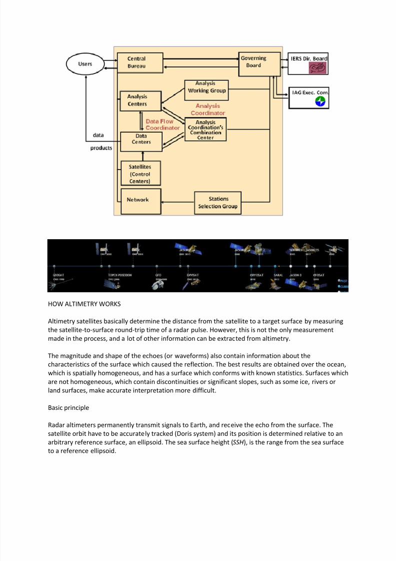
8112019 Tipos de oacuterbitasdocx
httpslidepdfcomreaderfulltipos-de-orbitasdocx 2130
Pulses and waveforms
Altimetry satellites basically determine the distance from the satellite to a target surface by measuringthe satellite-to-surface round-trip time of a radar pulse The magnitude and shape of the echoes (orwaveforms) also contain information about the characteristics of the surface which caused thereflection
Frequencies used
Several different frequencies are used for radar altimeters Each frequency band has its advantagesand disadvantages sensitivity to atmospheric perturbations for Ku-band better observation of icerain coastal zones land masses for Ka-band
FUTURE TECHNOLOGY IMPROVEMENTS
Satellite altimetry has proven to be a valuable source of data for a broad range of applications Looking beyond the
missions in operational service today future satellites will need to provide better spatial and temporal coverage so
that we can study further near the coasts or mesoscale variations and other phenomena more closely For the
medium term consideration is now being given to altimetry missions capable of scanning the ocean surface to
acquire data at scales of a few tens of kilometres passing over the same spots every few days Other projects onthe drawing board are based on constellations of dedicated low-cost microsatellites The use of opportunity
signals is also being considered with the possibility of retrieving reflected signals transmitted by satellites in the
Global Navigation Satellite System (GNSS)
Altimeter-interferometers
An altimeterinterferometer would include several altimeters mounted on masts which would acquire
measurements simultaneously thus providing continuous single- or multi-altimeter wide-area
coverage ltbrgt Further information
Constellations
One of the ways to improve altimetry resolution is to use several satellites at the same time Until now this has
been done with very different types of satellite The use of several identical satellites in constellation could reduce
costs (development costs and launch costs too for micro-satellites launched by the same rocket)
GNSS altimetry
One approach being pursued to achieve maximum altimetry data coverage is to receive reflected signals
transmitted by satellites in the Global Navigation Satellite System (GNSS) in particular from the Global Positioning
System (GPS) constellation and its European civil counterpart Galileo This concept is based on a satellite in near-
polar orbit (at an altitude of 400 to 500 km) retrieving signals emitted by multiple satellites and reflected by the
ocean surface then analysing these signals to compute sea surface height This concept is currently still only in the
study phase
RADIOMETRY PRINCIPLE
Microwave remote sensing uses passive microwave radiometers The microwaves have wavelength ranging from a
few kHz to THz The ldquopassiverdquo term means that it uses microwaves naturally radiated by the observed area (this is
different from the radar principle where the sensor transmits a microwave signal towards a target and detects the
backscattered radiation)
Radiometry principle
8112019 Tipos de oacuterbitasdocx
httpslidepdfcomreaderfulltipos-de-orbitasdocx 2230
Radiometry principle
Satellite passive microwave radiometers measure raw antenna counts from which we determine the antenna
temperature and then calculate the brightness temperature of the Earth Large antennas are used for the various
channels of the radiometer and in operation each antenna feedhorn passes a hot and cold target in order toprovide consistently calibrated raw counts Brightness temperature is a measure of the radiance of microwave
radiation traveling upward from the top of Earths atmosphere The conversion from radiometer counts to top-of-
the-atmosphere (TOA) brightness temperature is called the calibration process Several calibration processing
steps are required to derive the brightness temperature values
Radiometry applications
Microwave radiometer brightness temperatures are considered as a fundamental climate data record
and are the values from which we derive ocean measurements of wind speed water vapor cloud liquid
water rain rate and sea surface temperature
Missions
The main passive microwave radiometers are listed below (instrumentsatellite)
AMSR-E on Aqua
SSMI on DMSP F08 F10 F11 F13 F14 F15
SSMIS on DMSP F16 F17
WindSat on Coriolis
TMI on TRMM
AMSR2 GCOM - W1
Radiometers and altimeters
In the altimetry domain interesting radiometers are those that are on-board altimetric missions such
as JMR MWR AMR Altika radiometer etc These microwave radiometers measure the total water
vapor along the path viewed by the altimeter In addition to measuring total water vapor they are used
for range correction and to measure brightness temperatures
8112019 Tipos de oacuterbitasdocx
httpslidepdfcomreaderfulltipos-de-orbitasdocx 2330
Using generally two (238 37 GHz for Altika radiometer on board SARAL) or three different frequencies
(eg 187 238 340GHz for the AMR on-board OSTMJason-2) measurements acquired at each
frequency are combined to determine atmospheric water vapor and liquid water content Once the
water content is known it is possible to determine the correction to be applied for radar signal path
delays
Altimetry missions that operate without radiometer (eg Cryosat-2) can use estimation of wet
tropospheric correction coming from atmospheric models
For more information
JMR instrument on-board Jason-1
AMR instrument on-board OSTMJason-2
MWR instrument on-board Envisat
AltiKa on-board SARAL
The International Laser Ranging Service (ILRS) provides global satellite and lunar laser ranging data and their related
products to support geodetic and geophysical research activities as well as IERS products important to the
maintenance of an accurate International Terrestrial Reference Frame (ITRF) The service develops the necessary
global standardsspecifications and encourages international adherence to its conventions The ILRS is one of the
space geodetic services of the International Association of Geodesy (IAG)
The ILRS collects merges archives and distributes Satellite Laser Ranging (SLR) and Lunar Laser Ranging (LLR)
observation data sets of sufficient accuracy to satisfy the objectives of a wide range of scientific engineering and
operational applications and experimentation These data sets are used by the ILRS to generate a number of
scientific and operational data products including
Earth orientation parameters (polar motion and length of day)
Station coordinates and velocities of the ILRS tracking systems
Time-varying geocenter coordinates
Static and time-varying coefficients of the Earths gravity field
Centimeter accuracy satellite ephemerides
Fundamental physical constants
Lunar ephemerides and librations
Lunar orientation parameters
The accuracy of SLRLLR data products is sufficient to support a variety of scientific and operational applications
including
Realization of global accessibility to and the improvement of the International Terrestrial Reference Frame
(ITRF)
Monitoring three dimensional deformations of the solid Earth
Monitoring Earth rotation and polar motion
8112019 Tipos de oacuterbitasdocx
httpslidepdfcomreaderfulltipos-de-orbitasdocx 2430
Support the monitoring of variations in the topography and volume of the liquid Earth (ocean circulation mean
sea level ice sheet thickness wave heights etc)
Tidally generated variations in atmospheric mass distribution
Calibration of microwave tracking techniques
Picosecond global time transfer experiments
Astrometric observations including determination of the dynamic equinox obliquity of the ecliptic and the
precession constant
Gravitational and general relativistic studies including Einsteins Equivalence Principle the Robertson-Walker b
parameter and time rate of change of the gravitational constant
Lunar physics including the dissipation of rotational energy shape of the core-mantle boundary (Love Number
k2) and free librations and stimulating mechanisms
Solar System ties to the International Celestial Reference Frame (ICRF)
Satellite Laser Ranging (SLR) and Lunar Laser Ranging (LLR) use short-pulse lasers and state-of-the-art opticalreceivers and timing electronics to measure the two-way time of flight (and hence distance) from ground stations toretroreflector arrays on Earth orbiting satellites and the Moon Scientific products derived using SLR and LLR datainclude precise geocentric positions and motions of ground stations satellite orbits components of Earthrsquos gravityfield and their temporal variations Earth Orientation Parameters (EOP) precise lunar ephemerides and informationabout the internal structure of the Moon Laser ranging systems are already measuring the one-way distance toremote optical receivers in space and can perform very accurate time transfer between sites far apart Laser rangingactivities are organized under the International Laser Ranging Service (ILRS) which provides global satellite andlunar laser ranging data and their derived data products to support research in geodesy geophysics Lunar scienceand fundamental constants This includes data products that are fundamental to the International TerrestrialReference Frame (ITRF) which is established and maintained by the International Earth Rotation and ReferenceSystems Service (IERS) The ILRS develops the necessary global standardsspecifications for laser ranging activitiesand encourages international adherence to its conventions
Analysis Products
The ILRS provides a service to utilize Satellite and Lunar Laser Ranging data to generate geodetic geodynamic andgeophysical scientific products
Currently five SLR analysis groups (ASI DGFI GFZ JCET and NSGF) provide direct input for the official ILRSproducts (stationcoordinates and Earth Orientation Parameters EOPs) The results of the ILRS POS+EOP pilot project wereevaluated during the AWG meeting in San Fernando The five contributors were acknowledged and given an officialstatus In addition ASI was selected as the official ILRS primary combination center and DGFI was selected as theofficial ILRS backup combination center each for a two-year term As well as the contributors of individual solutionsthese combination centers must follow strict timelines and provide routine products of the highest possible qualityWeekly official ILRS products from these two combination centers are now available in SINEX format eachWednesday at CDDIS and EDC Analysis centers will again compete for the ILRS combination and backup center in
mid-2006 at the International Laser Ranging Workshop in Australia All groups are encouraged to develop (thequality of) their contributions furtherThe ILRS now generates weekly unconstrained solutions for station coordinates (valid for the mid-point of each 7-day interval) and EOPs (x-pole y-pole and Length-Of-Day (LOD) all of them for 1-day intervals) These results arestored in subdirectories of the form pos+eopYYMMDD where YYMMDD is the date (YY =2 digit year MM =2 digitmonth and DD=2 digit day) of the end of each 7-day interval Within each subdirectory one finds so-called individualsolutions and combination solutions that are explained belowFor the individual contributions to the POS+EOPproject filenames are of the form (examples reflect CDDIS archive)ftpcddisgsfcnasagovpubslrproductspos+eopYYMMDDCENTER pos+eopYYMMDDv1snxZHere CENTER is replaced by the name of the actual contributor It is the first solution that is generated for thisperiod and by this analysis center hence v1 If re-computations are necessary the version number will be
8112019 Tipos de oacuterbitasdocx
httpslidepdfcomreaderfulltipos-de-orbitasdocx 2530
increased by one solutions for new weeks will start with v1 however The results are stored in the SINEX format(snx) The reader is refered to the COMMENTS section of each solution (in the file itself) or more generalexplanations of SINEX for further details of the solution andor the formatThe official ILRS primary product on POS+EOP is labeled as
ftpcddisgsfcnasagovpubslrproductspos+eopYYMMDDilrsapos+eopYYMMDDv1snxZIn a similar fashion the EOP solutions (wrt ITRF2000) generated by the official ILRS primary combination centerare named
ftpcddisgsfcnasagovpubslrproductspos+eopYYMMDDilrsaeopYYMMDDv1snxZThe ILRS also has an official backup combination center and its products are labeled
ftpcddisgsfcnasagovpubslrproductspos+eopYYMMDDilrsbpos+eopYYMMDDv1snxZftpcddisgsfcnasagovpubslrproductspos+eopYYMMDDilrsbeopYYMMDDv1snxZCurrently the ILRS AWG is in the process of computing similar solutions for the years before the workshop in SanFernando At this moment the AWG works on solutions going back to the launch date of LAGEOS-2 (ie November1992) It is foreseen that this will (at a later stage) be followed by computations for the time frame extending back toSeptember 1983 the beginning of the MERIT campaign
Historical products include
Earth Orientation Parameters (EOP)o GSFC 98L01 solution
o CSR 95L01 solutiono Delft University of Technology 92L01 solutiono GeoForschungsZentrum 95L01 solutiono Centro di Geodesia Spaziale solutions
Coordinates and velocities of the tracking stations
Geocenter coordinates - IERS Geocenter campaign results IERS TN25
In Satellite Laser Ranging a short pulse of coherent light generated by a laser (Light Amplification by Stimulated
Emission of Radiation) is transmitted in a narrow beam to illuminate corner cube retroreflectors on the satellite Thereturn signal typically a few photons is collected by a telescope and the time-of-flight is measured Using informationabout the satellitersquos orbit the time-of-flight and the speed of light the location of the ranging station can bedetermined Similar data acquired by another station many kilometers distant from the first or on a different continentcan be used to determine the distance between stations to precisions of centimeters or better Repetitivemeasurements over months and years yield the changein distance or the motion of the Earthrsquos crust
Laser ranging to a near-Earth satellite was initiated byNASA in 1964 with the launch of the Beacon-B satelliteSince that time ranging precision spurred by scientificrequirements has improved by a factor of a thousandfrom a few meters to a few millimeters Similarly thenetwork of laser stations has grown from a fewexperimental sites to a global network of 43 stations inmore than 30 countries Most of these stations (33) arefunded by organizations other than NASA
During the past three decades the global Satellite LaserRanging (SLR) network has evolved into a powerfulsource of data for studies of the solid Earth and itsocean and atmospheric systems including
Detection and monitoring of tectonic plate motioncrustal deformation Earth rotation and polar motion
Modeling of the spatial and temporal variations of the Earthrsquos gravitational field
Determination of basin-scale ocean tides
Monitoring of millimeter-level variations in the location of the center of mass of the total Earth system (solidEarth-atmosphere-oceans)
Establishment and maintenance of the International Terrestrial Reference System (ITRS) and
Detection and monitoring of post-glacial rebound and subsidence
8112019 Tipos de oacuterbitasdocx
httpslidepdfcomreaderfulltipos-de-orbitasdocx 2630
In addition SLR provides precise orbit determination for spaceborne radar altimeter missions mapping the oceansurface (which are used to model global ocean circulation) for mapping volumetric changes in continental ice massesand for land topography It provides a means for subnanosecond global time transfer and a basis for special tests ofthe Theory of General Relativity
SLR uses special passive spacecraft in very stable orbits A low area to mass ratio minimizes the effects ofatmospheric drag and solar radiation pressure on the satellitersquos orbit
An example of such a satellite is the Laser Geodynamics Satellite (LAGEOS-1) which was launched by the UnitedStates in 1976 into a 6000 kilometer circular orbit with a near polar inclination Lageos-I and its sister satelliteLageos-II (built by the Agenzia Spaziale Italiana of Italy and launched in 1992 into a 6000 kilometer orbit but with aninclination of 51 degrees) have a 60 centimeter spherical shape and weigh 411 kilograms The exterior surface ofboth satellites is covered by 426 retroreflectors
Other satellites for SLR include Starlette (1000 km) and Stella (800 km) developed and launched by France Etalon-Iand -2 (19000 km) developed and launched by the former USSR and Ajisai (1500 km) developed and launched byJapan To obtain data for precise orbit determination retroreflectors are also mounted on the USFranceTopexPoseidon spacecraft the European Space Agency Earth Remote Sensing satellites (ERS-1 and 2) and on afew of the United States Global Positioning System (GPS) satellites
Fixed and mobile SLR systems have been used to acquire data for studies of crustal deformation and plate motion atscales from several hundred kilometers to several thousand kilometers to monitor polar motion and Earth rotationand to model the Earthrsquos gravity field
Lunar Laser Ranging (LLR)
During three US American Apollo missions (11 14 and 15) and two unmanned Soviet missions (Luna 17 and Luna21) retro-reflectors were deployed near the lunar landing sites between 1969 and 1973 The Lunar Laser Ranging(LLR) experiment has continuously provided range data for about 41 years generating about 17000 normal pointsThe main benefit of this space geodetic technique is the determination of a host of parameters describing lunarephemeris lunar physics the Moons interior various reference frames Earth orientation parameters and the Earth-Moon dynamics LLR has also become one of the strongest tools for testing Einsteins theory of general relativity inthe solar system no violations of general relativity have been found so far However the basis for all scientificanalyses is more high quality data from a well-distributed global LLR network More information is provided onthe LLR page
SLR and LLR are used in the following scientific research
Atmosphere-Hydrosphere-Cryosphere-Solid Earth Interactions Long-Term Dynamics of the Solid Earth Oceans and Ice Fields
Tides
Sensing of surface elevations
Mantle
Lunar Science
About IVS
Overview of IVS
IVS is an international collaboration of organizations which operate or support Very Long Baseline Interferometry(VLB I) components
The objectives of IVS are
to provide a service to support geodetic geophysical and astrometric research and operational activities
to promote research and development activities in all aspects of the geodetic and astrometric VLBI technique and
to interact with the community of users of VLBI products and to integrate VLBI into a global Earth observing system
The service aspect of IVS is meant to serve both outside users and the geodetic and astrometric community itselfBoth the contributors and users of data will be served
8112019 Tipos de oacuterbitasdocx
httpslidepdfcomreaderfulltipos-de-orbitasdocx 2730
IVS provides data and products for the scientific community Some of the products are
a terrestrial reference frame (TRF)
the international celestial reference frame (ICRF) and
Earth orientation parameters (EOP)
All IVS data and products are archived in data centers and are publically available for research in relatedareas of geodesy geophysics and astrometry
General The IVS observing program consists of various series of 24-hour observing sessions The
program is planned by the Observing Program Committee coordinated by the IVS Coordinating Center and
executed by the Network Stations Operation Centers andCorrelators The result of the observing program is
the data held in the Data Centers that is then available for analysis The flow of data and the resulting
products are shown graphically on the IVS structure and flow diagram Auxiliary data files such as schedule
and notes files are used to facilitate the observing operations They can be accessed from the IVS
Datapage or following procedures outlined in the Download Schedules page
IVS Live Following the success of the dynamic Web site for the IYA09 session Laboratoire
dAstrophysique de Bordeaux developed a generalized version of this tool for the entire IVS observingplan The resulting IVS Live site allows the user to monitor each session in real-time in terms of stations
scans and sources being used It provides links to Webcams and further ancillary information Follow
the countdown to the next IVS session or check out past or future IVS sessions using the session
calendar Many thanks to Arnaud Collioud and Bordeaux Observatory for making this possible
IVS Network Stations acquire geodetic and astrometric VLBI data Data acquisition at Network Stations is
controlled by schedules prepared by Operation Centers The raw data and log files are transmitted to
the Correlators for processing Details of the planned sessions are published in the Master Files maintained
by the Coordinating Center
About the IGS
The IGS global system of satellite tracking stations Data Centers and Analysis
Centers puts high-quality GPS data and data products on line in near real time to
meet the objectives of a wide range of scientific and engineering applications and
studies
The IGS collects archives and distributes GPS observation data sets of sufficientaccuracy to satisfy the objectives of a wide range of applications and experimentationThese data sets are used by the IGS to generate the data products mentioned abovewhich are made available to interested users through the Internet In particular theaccuracies of IGS products are sufficient for the improvement and extension of theInternational Terrestrial Reference Frame (ITRF) the monitoring of solid Earthdeformations the monitoring of Earth rotation and variations in the liquid Earth (sealevel ice-sheets etc) for scientific satellite orbit determinations ionospheremonitoring and recovery of precipitable water vapor measurements
8112019 Tipos de oacuterbitasdocx
httpslidepdfcomreaderfulltipos-de-orbitasdocx 2830
Mission
The primary mission of the International GPS Service as stated in the organizations
2002-2007 Strategic Plan is
The International GPS Service is committed to providing the highest quality data
and products as the standard for global navigation satellite systems (GNSS) in
support of Earth science research multidisciplinary applications and education
These activities aim to advance scientific understanding of the Earth system
components and their interactions as well as to facilitate other applications
benefiting society
The IGS Terms of Reference (comparable to the by-laws of the organization)describes in broad terms the goals and organization of the IGS
To accomplish its mission the IGS has a number of components an internationalnetwork of over 350 continuously operating dual-frequency GPS stations more than adozen regional and operational data centers three global data centers seven analysiscenters and a number of associate or regional analysis centers The Central Bureau forthe service is located at the Jet Propulsion Laboratory which maintains the CentralBureau Information System (CBIS) and ensures access to IGS products andinformation An international Governing Board oversees all aspects of the IGS TheIGS is an approved service of the International Association of Geodesy since 1994and is recognized as a member of the Federation of Astronomical and Geophysical
Data Analysis Services (FAGS) since 1996
For more information concerning IGS organization click here
History
Since the late 1980s the US Global Positioning System (GPS) constellation ofsatellites has come to play a major role in regional and global studies of Earth In theface of continued growth and diversification of GPS applications the worldwidescientific community has made an effort to promote international standards for GPS
data acquisition and analysis and to deploy and operate a common comprehensiveglobal tracking system
As part of this effort the IGS was formally recognized in 1993 by the InternationalAssociation of Geodesy (IAG) and began routine operations on January 1 1994 providing GPS orbits tracking data and other data products in support of geodeticand geophysical research In particular since January 1994 the IGS has madeavailable to its user community the IGS official orbit based on contributions from the
8112019 Tipos de oacuterbitasdocx
httpslidepdfcomreaderfulltipos-de-orbitasdocx 2930
seven current IGS Analysis Centers The IGS also supports a variety of governmentaland commercial activities and develops international GPS data standards andspecifications A description of the development and evolution of the IGS can befound in a number of publications with detailed documentation contained in the IGSAnnual Report Series published by the IGS Central Bureau via the World Wide WebThis series contains the yearly contributions from all components of service anddemonstrates that the key to success of the IGS has been the broad support of theinternational geodynamics and geodetic communities and their sponsoringorganizations This Information System is sponsored by the National Aeronautic andSpace Administration ( NASA) and managed for NASA by the Jet PropulsionLaboratory (JPL) of the California Institute of Technology (Caltech)
Operations
The IGS has developed a worldwide system comprising satellite tracking stations
Data Centers and Analysis Centers to put high-quality GPS data and data productson line within a day of observations For example following the NorthridgeCalifornia earthquake in January 1994 analysis teams using IGS-supplied data and products were able to quickly evaluate the disasters immediate effects by determiningstation displacements accurately to within a few millimeters
The IGS global network of permanent tracking stations each equipped with a GPSreceiver generates raw orbit and tracking data The Operational Data Centers whichare in direct contact with the tracking sites collect the raw receiver data and formatthem according to a common standard using a data format called Receiver
Independent Exchange (RINEX) The formatted data are then forwarded to theRegional or Global Data Centers To reduce electronic network traffic the RegionalData Centers are used to collect data from several Operational Data Centers beforetransmitting them to the Global Data Centers Data not used for global analyses arearchived and available for online access at the Regional Data Centers The GlobalData Centers archive and provide on-line access to tracking data and data products
Products and Applications
The IGS collects archives and distributes GPS observation data sets of sufficient
accuracy to meet the objectives of a wide range of scientific and engineeringapplications and studies These data sets are used to generate the following products
GPS satellite ephemerides
GLONASS satellite ephemerides
Earth rotation parameters
IGS tracking station coordinates and velocities
8112019 Tipos de oacuterbitasdocx
httpslidepdfcomreaderfulltipos-de-orbitasdocx 3030
GPS satellite and IGS tracking station clock information
Zenith tropospheric path delay estimates
Global ionospheric maps
IGS products support scientific activities such as improving and extending theInternational Earth Rotation Service (IERS) Terrestrial Reference Frame (ITRF)monitoring deformations of the solid Earth and variations in the liquid Earth (sea levelice sheets etc) and in Earth rotation determining orbits of scientific satellites andmonitoring the ionosphere For example geodynamics investigators who use GPS inlocal regions can include data from one or more nearby IGS stations fix the sitecoordinates from such stations to their ITRF values and more importantly use the precise IGS orbits without further refinement Data from an investigators localnetwork can then be analyzed with maximum accuracy and minimum computational burden Furthermore the results will be in a well-defined global reference frame
An additional aspect of IGS products is for the densification of the ITRF at a moreregional level This is accomplished through the rigorous combination of regional orlocal network solutions utilizing the Solution Independent Exchange Format (SINEX) and a process defined in the densification section
In the future the IGS infrastructure could become a valuable asset for support of newground-based applications and could also contribute to space-based missions inwhich highly accurate flight and ground differential techniques are required
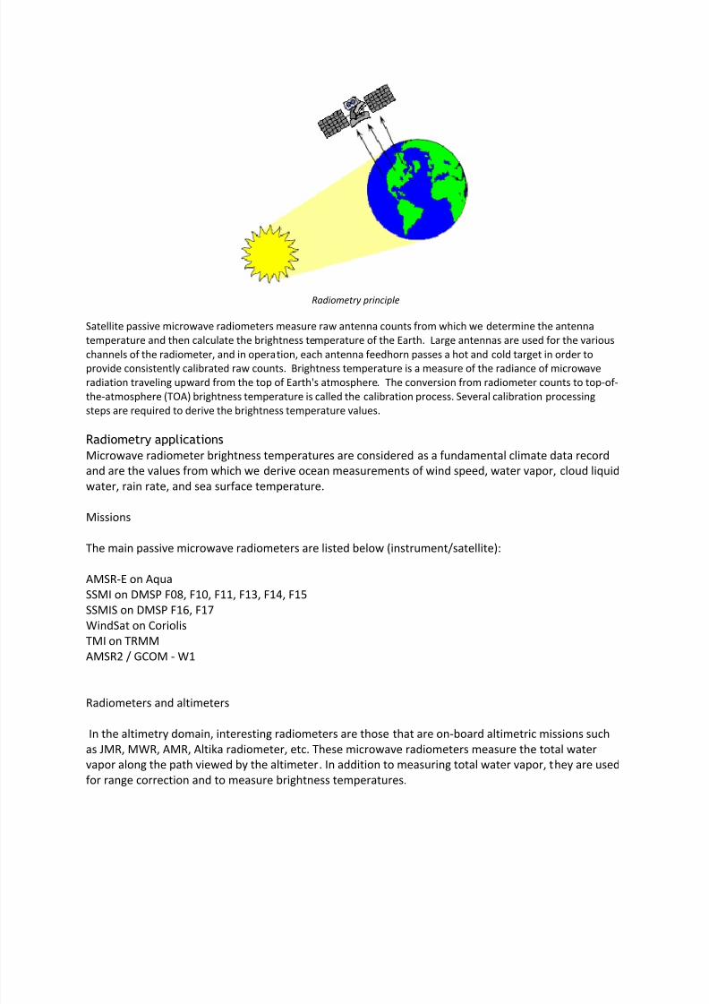
8112019 Tipos de oacuterbitasdocx
httpslidepdfcomreaderfulltipos-de-orbitasdocx 2430
Support the monitoring of variations in the topography and volume of the liquid Earth (ocean circulation mean
sea level ice sheet thickness wave heights etc)
Tidally generated variations in atmospheric mass distribution
Calibration of microwave tracking techniques
Picosecond global time transfer experiments
Astrometric observations including determination of the dynamic equinox obliquity of the ecliptic and the
precession constant
Gravitational and general relativistic studies including Einsteins Equivalence Principle the Robertson-Walker b
parameter and time rate of change of the gravitational constant
Lunar physics including the dissipation of rotational energy shape of the core-mantle boundary (Love Number
k2) and free librations and stimulating mechanisms
Solar System ties to the International Celestial Reference Frame (ICRF)
Satellite Laser Ranging (SLR) and Lunar Laser Ranging (LLR) use short-pulse lasers and state-of-the-art opticalreceivers and timing electronics to measure the two-way time of flight (and hence distance) from ground stations toretroreflector arrays on Earth orbiting satellites and the Moon Scientific products derived using SLR and LLR datainclude precise geocentric positions and motions of ground stations satellite orbits components of Earthrsquos gravityfield and their temporal variations Earth Orientation Parameters (EOP) precise lunar ephemerides and informationabout the internal structure of the Moon Laser ranging systems are already measuring the one-way distance toremote optical receivers in space and can perform very accurate time transfer between sites far apart Laser rangingactivities are organized under the International Laser Ranging Service (ILRS) which provides global satellite andlunar laser ranging data and their derived data products to support research in geodesy geophysics Lunar scienceand fundamental constants This includes data products that are fundamental to the International TerrestrialReference Frame (ITRF) which is established and maintained by the International Earth Rotation and ReferenceSystems Service (IERS) The ILRS develops the necessary global standardsspecifications for laser ranging activitiesand encourages international adherence to its conventions
Analysis Products
The ILRS provides a service to utilize Satellite and Lunar Laser Ranging data to generate geodetic geodynamic andgeophysical scientific products
Currently five SLR analysis groups (ASI DGFI GFZ JCET and NSGF) provide direct input for the official ILRSproducts (stationcoordinates and Earth Orientation Parameters EOPs) The results of the ILRS POS+EOP pilot project wereevaluated during the AWG meeting in San Fernando The five contributors were acknowledged and given an officialstatus In addition ASI was selected as the official ILRS primary combination center and DGFI was selected as theofficial ILRS backup combination center each for a two-year term As well as the contributors of individual solutionsthese combination centers must follow strict timelines and provide routine products of the highest possible qualityWeekly official ILRS products from these two combination centers are now available in SINEX format eachWednesday at CDDIS and EDC Analysis centers will again compete for the ILRS combination and backup center in
mid-2006 at the International Laser Ranging Workshop in Australia All groups are encouraged to develop (thequality of) their contributions furtherThe ILRS now generates weekly unconstrained solutions for station coordinates (valid for the mid-point of each 7-day interval) and EOPs (x-pole y-pole and Length-Of-Day (LOD) all of them for 1-day intervals) These results arestored in subdirectories of the form pos+eopYYMMDD where YYMMDD is the date (YY =2 digit year MM =2 digitmonth and DD=2 digit day) of the end of each 7-day interval Within each subdirectory one finds so-called individualsolutions and combination solutions that are explained belowFor the individual contributions to the POS+EOPproject filenames are of the form (examples reflect CDDIS archive)ftpcddisgsfcnasagovpubslrproductspos+eopYYMMDDCENTER pos+eopYYMMDDv1snxZHere CENTER is replaced by the name of the actual contributor It is the first solution that is generated for thisperiod and by this analysis center hence v1 If re-computations are necessary the version number will be
8112019 Tipos de oacuterbitasdocx
httpslidepdfcomreaderfulltipos-de-orbitasdocx 2530
increased by one solutions for new weeks will start with v1 however The results are stored in the SINEX format(snx) The reader is refered to the COMMENTS section of each solution (in the file itself) or more generalexplanations of SINEX for further details of the solution andor the formatThe official ILRS primary product on POS+EOP is labeled as
ftpcddisgsfcnasagovpubslrproductspos+eopYYMMDDilrsapos+eopYYMMDDv1snxZIn a similar fashion the EOP solutions (wrt ITRF2000) generated by the official ILRS primary combination centerare named
ftpcddisgsfcnasagovpubslrproductspos+eopYYMMDDilrsaeopYYMMDDv1snxZThe ILRS also has an official backup combination center and its products are labeled
ftpcddisgsfcnasagovpubslrproductspos+eopYYMMDDilrsbpos+eopYYMMDDv1snxZftpcddisgsfcnasagovpubslrproductspos+eopYYMMDDilrsbeopYYMMDDv1snxZCurrently the ILRS AWG is in the process of computing similar solutions for the years before the workshop in SanFernando At this moment the AWG works on solutions going back to the launch date of LAGEOS-2 (ie November1992) It is foreseen that this will (at a later stage) be followed by computations for the time frame extending back toSeptember 1983 the beginning of the MERIT campaign
Historical products include
Earth Orientation Parameters (EOP)o GSFC 98L01 solution
o CSR 95L01 solutiono Delft University of Technology 92L01 solutiono GeoForschungsZentrum 95L01 solutiono Centro di Geodesia Spaziale solutions
Coordinates and velocities of the tracking stations
Geocenter coordinates - IERS Geocenter campaign results IERS TN25
In Satellite Laser Ranging a short pulse of coherent light generated by a laser (Light Amplification by Stimulated
Emission of Radiation) is transmitted in a narrow beam to illuminate corner cube retroreflectors on the satellite Thereturn signal typically a few photons is collected by a telescope and the time-of-flight is measured Using informationabout the satellitersquos orbit the time-of-flight and the speed of light the location of the ranging station can bedetermined Similar data acquired by another station many kilometers distant from the first or on a different continentcan be used to determine the distance between stations to precisions of centimeters or better Repetitivemeasurements over months and years yield the changein distance or the motion of the Earthrsquos crust
Laser ranging to a near-Earth satellite was initiated byNASA in 1964 with the launch of the Beacon-B satelliteSince that time ranging precision spurred by scientificrequirements has improved by a factor of a thousandfrom a few meters to a few millimeters Similarly thenetwork of laser stations has grown from a fewexperimental sites to a global network of 43 stations inmore than 30 countries Most of these stations (33) arefunded by organizations other than NASA
During the past three decades the global Satellite LaserRanging (SLR) network has evolved into a powerfulsource of data for studies of the solid Earth and itsocean and atmospheric systems including
Detection and monitoring of tectonic plate motioncrustal deformation Earth rotation and polar motion
Modeling of the spatial and temporal variations of the Earthrsquos gravitational field
Determination of basin-scale ocean tides
Monitoring of millimeter-level variations in the location of the center of mass of the total Earth system (solidEarth-atmosphere-oceans)
Establishment and maintenance of the International Terrestrial Reference System (ITRS) and
Detection and monitoring of post-glacial rebound and subsidence
8112019 Tipos de oacuterbitasdocx
httpslidepdfcomreaderfulltipos-de-orbitasdocx 2630
In addition SLR provides precise orbit determination for spaceborne radar altimeter missions mapping the oceansurface (which are used to model global ocean circulation) for mapping volumetric changes in continental ice massesand for land topography It provides a means for subnanosecond global time transfer and a basis for special tests ofthe Theory of General Relativity
SLR uses special passive spacecraft in very stable orbits A low area to mass ratio minimizes the effects ofatmospheric drag and solar radiation pressure on the satellitersquos orbit
An example of such a satellite is the Laser Geodynamics Satellite (LAGEOS-1) which was launched by the UnitedStates in 1976 into a 6000 kilometer circular orbit with a near polar inclination Lageos-I and its sister satelliteLageos-II (built by the Agenzia Spaziale Italiana of Italy and launched in 1992 into a 6000 kilometer orbit but with aninclination of 51 degrees) have a 60 centimeter spherical shape and weigh 411 kilograms The exterior surface ofboth satellites is covered by 426 retroreflectors
Other satellites for SLR include Starlette (1000 km) and Stella (800 km) developed and launched by France Etalon-Iand -2 (19000 km) developed and launched by the former USSR and Ajisai (1500 km) developed and launched byJapan To obtain data for precise orbit determination retroreflectors are also mounted on the USFranceTopexPoseidon spacecraft the European Space Agency Earth Remote Sensing satellites (ERS-1 and 2) and on afew of the United States Global Positioning System (GPS) satellites
Fixed and mobile SLR systems have been used to acquire data for studies of crustal deformation and plate motion atscales from several hundred kilometers to several thousand kilometers to monitor polar motion and Earth rotationand to model the Earthrsquos gravity field
Lunar Laser Ranging (LLR)
During three US American Apollo missions (11 14 and 15) and two unmanned Soviet missions (Luna 17 and Luna21) retro-reflectors were deployed near the lunar landing sites between 1969 and 1973 The Lunar Laser Ranging(LLR) experiment has continuously provided range data for about 41 years generating about 17000 normal pointsThe main benefit of this space geodetic technique is the determination of a host of parameters describing lunarephemeris lunar physics the Moons interior various reference frames Earth orientation parameters and the Earth-Moon dynamics LLR has also become one of the strongest tools for testing Einsteins theory of general relativity inthe solar system no violations of general relativity have been found so far However the basis for all scientificanalyses is more high quality data from a well-distributed global LLR network More information is provided onthe LLR page
SLR and LLR are used in the following scientific research
Atmosphere-Hydrosphere-Cryosphere-Solid Earth Interactions Long-Term Dynamics of the Solid Earth Oceans and Ice Fields
Tides
Sensing of surface elevations
Mantle
Lunar Science
About IVS
Overview of IVS
IVS is an international collaboration of organizations which operate or support Very Long Baseline Interferometry(VLB I) components
The objectives of IVS are
to provide a service to support geodetic geophysical and astrometric research and operational activities
to promote research and development activities in all aspects of the geodetic and astrometric VLBI technique and
to interact with the community of users of VLBI products and to integrate VLBI into a global Earth observing system
The service aspect of IVS is meant to serve both outside users and the geodetic and astrometric community itselfBoth the contributors and users of data will be served
8112019 Tipos de oacuterbitasdocx
httpslidepdfcomreaderfulltipos-de-orbitasdocx 2730
IVS provides data and products for the scientific community Some of the products are
a terrestrial reference frame (TRF)
the international celestial reference frame (ICRF) and
Earth orientation parameters (EOP)
All IVS data and products are archived in data centers and are publically available for research in relatedareas of geodesy geophysics and astrometry
General The IVS observing program consists of various series of 24-hour observing sessions The
program is planned by the Observing Program Committee coordinated by the IVS Coordinating Center and
executed by the Network Stations Operation Centers andCorrelators The result of the observing program is
the data held in the Data Centers that is then available for analysis The flow of data and the resulting
products are shown graphically on the IVS structure and flow diagram Auxiliary data files such as schedule
and notes files are used to facilitate the observing operations They can be accessed from the IVS
Datapage or following procedures outlined in the Download Schedules page
IVS Live Following the success of the dynamic Web site for the IYA09 session Laboratoire
dAstrophysique de Bordeaux developed a generalized version of this tool for the entire IVS observingplan The resulting IVS Live site allows the user to monitor each session in real-time in terms of stations
scans and sources being used It provides links to Webcams and further ancillary information Follow
the countdown to the next IVS session or check out past or future IVS sessions using the session
calendar Many thanks to Arnaud Collioud and Bordeaux Observatory for making this possible
IVS Network Stations acquire geodetic and astrometric VLBI data Data acquisition at Network Stations is
controlled by schedules prepared by Operation Centers The raw data and log files are transmitted to
the Correlators for processing Details of the planned sessions are published in the Master Files maintained
by the Coordinating Center
About the IGS
The IGS global system of satellite tracking stations Data Centers and Analysis
Centers puts high-quality GPS data and data products on line in near real time to
meet the objectives of a wide range of scientific and engineering applications and
studies
The IGS collects archives and distributes GPS observation data sets of sufficientaccuracy to satisfy the objectives of a wide range of applications and experimentationThese data sets are used by the IGS to generate the data products mentioned abovewhich are made available to interested users through the Internet In particular theaccuracies of IGS products are sufficient for the improvement and extension of theInternational Terrestrial Reference Frame (ITRF) the monitoring of solid Earthdeformations the monitoring of Earth rotation and variations in the liquid Earth (sealevel ice-sheets etc) for scientific satellite orbit determinations ionospheremonitoring and recovery of precipitable water vapor measurements
8112019 Tipos de oacuterbitasdocx
httpslidepdfcomreaderfulltipos-de-orbitasdocx 2830
Mission
The primary mission of the International GPS Service as stated in the organizations
2002-2007 Strategic Plan is
The International GPS Service is committed to providing the highest quality data
and products as the standard for global navigation satellite systems (GNSS) in
support of Earth science research multidisciplinary applications and education
These activities aim to advance scientific understanding of the Earth system
components and their interactions as well as to facilitate other applications
benefiting society
The IGS Terms of Reference (comparable to the by-laws of the organization)describes in broad terms the goals and organization of the IGS
To accomplish its mission the IGS has a number of components an internationalnetwork of over 350 continuously operating dual-frequency GPS stations more than adozen regional and operational data centers three global data centers seven analysiscenters and a number of associate or regional analysis centers The Central Bureau forthe service is located at the Jet Propulsion Laboratory which maintains the CentralBureau Information System (CBIS) and ensures access to IGS products andinformation An international Governing Board oversees all aspects of the IGS TheIGS is an approved service of the International Association of Geodesy since 1994and is recognized as a member of the Federation of Astronomical and Geophysical
Data Analysis Services (FAGS) since 1996
For more information concerning IGS organization click here
History
Since the late 1980s the US Global Positioning System (GPS) constellation ofsatellites has come to play a major role in regional and global studies of Earth In theface of continued growth and diversification of GPS applications the worldwidescientific community has made an effort to promote international standards for GPS
data acquisition and analysis and to deploy and operate a common comprehensiveglobal tracking system
As part of this effort the IGS was formally recognized in 1993 by the InternationalAssociation of Geodesy (IAG) and began routine operations on January 1 1994 providing GPS orbits tracking data and other data products in support of geodeticand geophysical research In particular since January 1994 the IGS has madeavailable to its user community the IGS official orbit based on contributions from the
8112019 Tipos de oacuterbitasdocx
httpslidepdfcomreaderfulltipos-de-orbitasdocx 2930
seven current IGS Analysis Centers The IGS also supports a variety of governmentaland commercial activities and develops international GPS data standards andspecifications A description of the development and evolution of the IGS can befound in a number of publications with detailed documentation contained in the IGSAnnual Report Series published by the IGS Central Bureau via the World Wide WebThis series contains the yearly contributions from all components of service anddemonstrates that the key to success of the IGS has been the broad support of theinternational geodynamics and geodetic communities and their sponsoringorganizations This Information System is sponsored by the National Aeronautic andSpace Administration ( NASA) and managed for NASA by the Jet PropulsionLaboratory (JPL) of the California Institute of Technology (Caltech)
Operations
The IGS has developed a worldwide system comprising satellite tracking stations
Data Centers and Analysis Centers to put high-quality GPS data and data productson line within a day of observations For example following the NorthridgeCalifornia earthquake in January 1994 analysis teams using IGS-supplied data and products were able to quickly evaluate the disasters immediate effects by determiningstation displacements accurately to within a few millimeters
The IGS global network of permanent tracking stations each equipped with a GPSreceiver generates raw orbit and tracking data The Operational Data Centers whichare in direct contact with the tracking sites collect the raw receiver data and formatthem according to a common standard using a data format called Receiver
Independent Exchange (RINEX) The formatted data are then forwarded to theRegional or Global Data Centers To reduce electronic network traffic the RegionalData Centers are used to collect data from several Operational Data Centers beforetransmitting them to the Global Data Centers Data not used for global analyses arearchived and available for online access at the Regional Data Centers The GlobalData Centers archive and provide on-line access to tracking data and data products
Products and Applications
The IGS collects archives and distributes GPS observation data sets of sufficient
accuracy to meet the objectives of a wide range of scientific and engineeringapplications and studies These data sets are used to generate the following products
GPS satellite ephemerides
GLONASS satellite ephemerides
Earth rotation parameters
IGS tracking station coordinates and velocities
8112019 Tipos de oacuterbitasdocx
httpslidepdfcomreaderfulltipos-de-orbitasdocx 3030
GPS satellite and IGS tracking station clock information
Zenith tropospheric path delay estimates
Global ionospheric maps
IGS products support scientific activities such as improving and extending theInternational Earth Rotation Service (IERS) Terrestrial Reference Frame (ITRF)monitoring deformations of the solid Earth and variations in the liquid Earth (sea levelice sheets etc) and in Earth rotation determining orbits of scientific satellites andmonitoring the ionosphere For example geodynamics investigators who use GPS inlocal regions can include data from one or more nearby IGS stations fix the sitecoordinates from such stations to their ITRF values and more importantly use the precise IGS orbits without further refinement Data from an investigators localnetwork can then be analyzed with maximum accuracy and minimum computational burden Furthermore the results will be in a well-defined global reference frame
An additional aspect of IGS products is for the densification of the ITRF at a moreregional level This is accomplished through the rigorous combination of regional orlocal network solutions utilizing the Solution Independent Exchange Format (SINEX) and a process defined in the densification section
In the future the IGS infrastructure could become a valuable asset for support of newground-based applications and could also contribute to space-based missions inwhich highly accurate flight and ground differential techniques are required
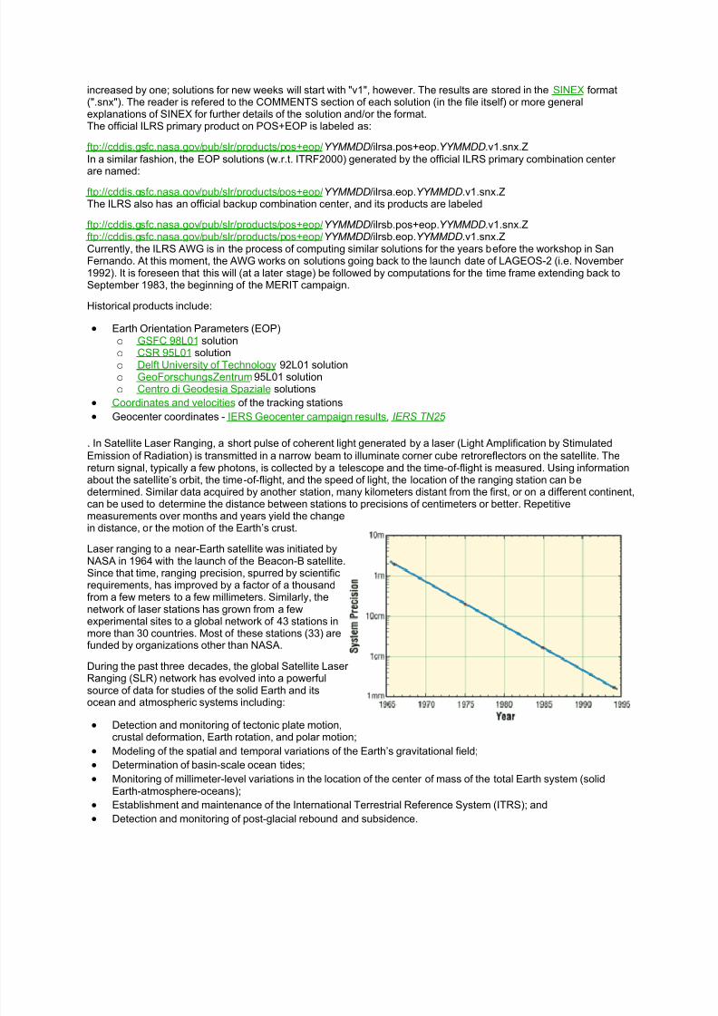
8112019 Tipos de oacuterbitasdocx
httpslidepdfcomreaderfulltipos-de-orbitasdocx 2530
increased by one solutions for new weeks will start with v1 however The results are stored in the SINEX format(snx) The reader is refered to the COMMENTS section of each solution (in the file itself) or more generalexplanations of SINEX for further details of the solution andor the formatThe official ILRS primary product on POS+EOP is labeled as
ftpcddisgsfcnasagovpubslrproductspos+eopYYMMDDilrsapos+eopYYMMDDv1snxZIn a similar fashion the EOP solutions (wrt ITRF2000) generated by the official ILRS primary combination centerare named
ftpcddisgsfcnasagovpubslrproductspos+eopYYMMDDilrsaeopYYMMDDv1snxZThe ILRS also has an official backup combination center and its products are labeled
ftpcddisgsfcnasagovpubslrproductspos+eopYYMMDDilrsbpos+eopYYMMDDv1snxZftpcddisgsfcnasagovpubslrproductspos+eopYYMMDDilrsbeopYYMMDDv1snxZCurrently the ILRS AWG is in the process of computing similar solutions for the years before the workshop in SanFernando At this moment the AWG works on solutions going back to the launch date of LAGEOS-2 (ie November1992) It is foreseen that this will (at a later stage) be followed by computations for the time frame extending back toSeptember 1983 the beginning of the MERIT campaign
Historical products include
Earth Orientation Parameters (EOP)o GSFC 98L01 solution
o CSR 95L01 solutiono Delft University of Technology 92L01 solutiono GeoForschungsZentrum 95L01 solutiono Centro di Geodesia Spaziale solutions
Coordinates and velocities of the tracking stations
Geocenter coordinates - IERS Geocenter campaign results IERS TN25
In Satellite Laser Ranging a short pulse of coherent light generated by a laser (Light Amplification by Stimulated
Emission of Radiation) is transmitted in a narrow beam to illuminate corner cube retroreflectors on the satellite Thereturn signal typically a few photons is collected by a telescope and the time-of-flight is measured Using informationabout the satellitersquos orbit the time-of-flight and the speed of light the location of the ranging station can bedetermined Similar data acquired by another station many kilometers distant from the first or on a different continentcan be used to determine the distance between stations to precisions of centimeters or better Repetitivemeasurements over months and years yield the changein distance or the motion of the Earthrsquos crust
Laser ranging to a near-Earth satellite was initiated byNASA in 1964 with the launch of the Beacon-B satelliteSince that time ranging precision spurred by scientificrequirements has improved by a factor of a thousandfrom a few meters to a few millimeters Similarly thenetwork of laser stations has grown from a fewexperimental sites to a global network of 43 stations inmore than 30 countries Most of these stations (33) arefunded by organizations other than NASA
During the past three decades the global Satellite LaserRanging (SLR) network has evolved into a powerfulsource of data for studies of the solid Earth and itsocean and atmospheric systems including
Detection and monitoring of tectonic plate motioncrustal deformation Earth rotation and polar motion
Modeling of the spatial and temporal variations of the Earthrsquos gravitational field
Determination of basin-scale ocean tides
Monitoring of millimeter-level variations in the location of the center of mass of the total Earth system (solidEarth-atmosphere-oceans)
Establishment and maintenance of the International Terrestrial Reference System (ITRS) and
Detection and monitoring of post-glacial rebound and subsidence
8112019 Tipos de oacuterbitasdocx
httpslidepdfcomreaderfulltipos-de-orbitasdocx 2630
In addition SLR provides precise orbit determination for spaceborne radar altimeter missions mapping the oceansurface (which are used to model global ocean circulation) for mapping volumetric changes in continental ice massesand for land topography It provides a means for subnanosecond global time transfer and a basis for special tests ofthe Theory of General Relativity
SLR uses special passive spacecraft in very stable orbits A low area to mass ratio minimizes the effects ofatmospheric drag and solar radiation pressure on the satellitersquos orbit
An example of such a satellite is the Laser Geodynamics Satellite (LAGEOS-1) which was launched by the UnitedStates in 1976 into a 6000 kilometer circular orbit with a near polar inclination Lageos-I and its sister satelliteLageos-II (built by the Agenzia Spaziale Italiana of Italy and launched in 1992 into a 6000 kilometer orbit but with aninclination of 51 degrees) have a 60 centimeter spherical shape and weigh 411 kilograms The exterior surface ofboth satellites is covered by 426 retroreflectors
Other satellites for SLR include Starlette (1000 km) and Stella (800 km) developed and launched by France Etalon-Iand -2 (19000 km) developed and launched by the former USSR and Ajisai (1500 km) developed and launched byJapan To obtain data for precise orbit determination retroreflectors are also mounted on the USFranceTopexPoseidon spacecraft the European Space Agency Earth Remote Sensing satellites (ERS-1 and 2) and on afew of the United States Global Positioning System (GPS) satellites
Fixed and mobile SLR systems have been used to acquire data for studies of crustal deformation and plate motion atscales from several hundred kilometers to several thousand kilometers to monitor polar motion and Earth rotationand to model the Earthrsquos gravity field
Lunar Laser Ranging (LLR)
During three US American Apollo missions (11 14 and 15) and two unmanned Soviet missions (Luna 17 and Luna21) retro-reflectors were deployed near the lunar landing sites between 1969 and 1973 The Lunar Laser Ranging(LLR) experiment has continuously provided range data for about 41 years generating about 17000 normal pointsThe main benefit of this space geodetic technique is the determination of a host of parameters describing lunarephemeris lunar physics the Moons interior various reference frames Earth orientation parameters and the Earth-Moon dynamics LLR has also become one of the strongest tools for testing Einsteins theory of general relativity inthe solar system no violations of general relativity have been found so far However the basis for all scientificanalyses is more high quality data from a well-distributed global LLR network More information is provided onthe LLR page
SLR and LLR are used in the following scientific research
Atmosphere-Hydrosphere-Cryosphere-Solid Earth Interactions Long-Term Dynamics of the Solid Earth Oceans and Ice Fields
Tides
Sensing of surface elevations
Mantle
Lunar Science
About IVS
Overview of IVS
IVS is an international collaboration of organizations which operate or support Very Long Baseline Interferometry(VLB I) components
The objectives of IVS are
to provide a service to support geodetic geophysical and astrometric research and operational activities
to promote research and development activities in all aspects of the geodetic and astrometric VLBI technique and
to interact with the community of users of VLBI products and to integrate VLBI into a global Earth observing system
The service aspect of IVS is meant to serve both outside users and the geodetic and astrometric community itselfBoth the contributors and users of data will be served
8112019 Tipos de oacuterbitasdocx
httpslidepdfcomreaderfulltipos-de-orbitasdocx 2730
IVS provides data and products for the scientific community Some of the products are
a terrestrial reference frame (TRF)
the international celestial reference frame (ICRF) and
Earth orientation parameters (EOP)
All IVS data and products are archived in data centers and are publically available for research in relatedareas of geodesy geophysics and astrometry
General The IVS observing program consists of various series of 24-hour observing sessions The
program is planned by the Observing Program Committee coordinated by the IVS Coordinating Center and
executed by the Network Stations Operation Centers andCorrelators The result of the observing program is
the data held in the Data Centers that is then available for analysis The flow of data and the resulting
products are shown graphically on the IVS structure and flow diagram Auxiliary data files such as schedule
and notes files are used to facilitate the observing operations They can be accessed from the IVS
Datapage or following procedures outlined in the Download Schedules page
IVS Live Following the success of the dynamic Web site for the IYA09 session Laboratoire
dAstrophysique de Bordeaux developed a generalized version of this tool for the entire IVS observingplan The resulting IVS Live site allows the user to monitor each session in real-time in terms of stations
scans and sources being used It provides links to Webcams and further ancillary information Follow
the countdown to the next IVS session or check out past or future IVS sessions using the session
calendar Many thanks to Arnaud Collioud and Bordeaux Observatory for making this possible
IVS Network Stations acquire geodetic and astrometric VLBI data Data acquisition at Network Stations is
controlled by schedules prepared by Operation Centers The raw data and log files are transmitted to
the Correlators for processing Details of the planned sessions are published in the Master Files maintained
by the Coordinating Center
About the IGS
The IGS global system of satellite tracking stations Data Centers and Analysis
Centers puts high-quality GPS data and data products on line in near real time to
meet the objectives of a wide range of scientific and engineering applications and
studies
The IGS collects archives and distributes GPS observation data sets of sufficientaccuracy to satisfy the objectives of a wide range of applications and experimentationThese data sets are used by the IGS to generate the data products mentioned abovewhich are made available to interested users through the Internet In particular theaccuracies of IGS products are sufficient for the improvement and extension of theInternational Terrestrial Reference Frame (ITRF) the monitoring of solid Earthdeformations the monitoring of Earth rotation and variations in the liquid Earth (sealevel ice-sheets etc) for scientific satellite orbit determinations ionospheremonitoring and recovery of precipitable water vapor measurements
8112019 Tipos de oacuterbitasdocx
httpslidepdfcomreaderfulltipos-de-orbitasdocx 2830
Mission
The primary mission of the International GPS Service as stated in the organizations
2002-2007 Strategic Plan is
The International GPS Service is committed to providing the highest quality data
and products as the standard for global navigation satellite systems (GNSS) in
support of Earth science research multidisciplinary applications and education
These activities aim to advance scientific understanding of the Earth system
components and their interactions as well as to facilitate other applications
benefiting society
The IGS Terms of Reference (comparable to the by-laws of the organization)describes in broad terms the goals and organization of the IGS
To accomplish its mission the IGS has a number of components an internationalnetwork of over 350 continuously operating dual-frequency GPS stations more than adozen regional and operational data centers three global data centers seven analysiscenters and a number of associate or regional analysis centers The Central Bureau forthe service is located at the Jet Propulsion Laboratory which maintains the CentralBureau Information System (CBIS) and ensures access to IGS products andinformation An international Governing Board oversees all aspects of the IGS TheIGS is an approved service of the International Association of Geodesy since 1994and is recognized as a member of the Federation of Astronomical and Geophysical
Data Analysis Services (FAGS) since 1996
For more information concerning IGS organization click here
History
Since the late 1980s the US Global Positioning System (GPS) constellation ofsatellites has come to play a major role in regional and global studies of Earth In theface of continued growth and diversification of GPS applications the worldwidescientific community has made an effort to promote international standards for GPS
data acquisition and analysis and to deploy and operate a common comprehensiveglobal tracking system
As part of this effort the IGS was formally recognized in 1993 by the InternationalAssociation of Geodesy (IAG) and began routine operations on January 1 1994 providing GPS orbits tracking data and other data products in support of geodeticand geophysical research In particular since January 1994 the IGS has madeavailable to its user community the IGS official orbit based on contributions from the
8112019 Tipos de oacuterbitasdocx
httpslidepdfcomreaderfulltipos-de-orbitasdocx 2930
seven current IGS Analysis Centers The IGS also supports a variety of governmentaland commercial activities and develops international GPS data standards andspecifications A description of the development and evolution of the IGS can befound in a number of publications with detailed documentation contained in the IGSAnnual Report Series published by the IGS Central Bureau via the World Wide WebThis series contains the yearly contributions from all components of service anddemonstrates that the key to success of the IGS has been the broad support of theinternational geodynamics and geodetic communities and their sponsoringorganizations This Information System is sponsored by the National Aeronautic andSpace Administration ( NASA) and managed for NASA by the Jet PropulsionLaboratory (JPL) of the California Institute of Technology (Caltech)
Operations
The IGS has developed a worldwide system comprising satellite tracking stations
Data Centers and Analysis Centers to put high-quality GPS data and data productson line within a day of observations For example following the NorthridgeCalifornia earthquake in January 1994 analysis teams using IGS-supplied data and products were able to quickly evaluate the disasters immediate effects by determiningstation displacements accurately to within a few millimeters
The IGS global network of permanent tracking stations each equipped with a GPSreceiver generates raw orbit and tracking data The Operational Data Centers whichare in direct contact with the tracking sites collect the raw receiver data and formatthem according to a common standard using a data format called Receiver
Independent Exchange (RINEX) The formatted data are then forwarded to theRegional or Global Data Centers To reduce electronic network traffic the RegionalData Centers are used to collect data from several Operational Data Centers beforetransmitting them to the Global Data Centers Data not used for global analyses arearchived and available for online access at the Regional Data Centers The GlobalData Centers archive and provide on-line access to tracking data and data products
Products and Applications
The IGS collects archives and distributes GPS observation data sets of sufficient
accuracy to meet the objectives of a wide range of scientific and engineeringapplications and studies These data sets are used to generate the following products
GPS satellite ephemerides
GLONASS satellite ephemerides
Earth rotation parameters
IGS tracking station coordinates and velocities
8112019 Tipos de oacuterbitasdocx
httpslidepdfcomreaderfulltipos-de-orbitasdocx 3030
GPS satellite and IGS tracking station clock information
Zenith tropospheric path delay estimates
Global ionospheric maps
IGS products support scientific activities such as improving and extending theInternational Earth Rotation Service (IERS) Terrestrial Reference Frame (ITRF)monitoring deformations of the solid Earth and variations in the liquid Earth (sea levelice sheets etc) and in Earth rotation determining orbits of scientific satellites andmonitoring the ionosphere For example geodynamics investigators who use GPS inlocal regions can include data from one or more nearby IGS stations fix the sitecoordinates from such stations to their ITRF values and more importantly use the precise IGS orbits without further refinement Data from an investigators localnetwork can then be analyzed with maximum accuracy and minimum computational burden Furthermore the results will be in a well-defined global reference frame
An additional aspect of IGS products is for the densification of the ITRF at a moreregional level This is accomplished through the rigorous combination of regional orlocal network solutions utilizing the Solution Independent Exchange Format (SINEX) and a process defined in the densification section
In the future the IGS infrastructure could become a valuable asset for support of newground-based applications and could also contribute to space-based missions inwhich highly accurate flight and ground differential techniques are required
8112019 Tipos de oacuterbitasdocx
httpslidepdfcomreaderfulltipos-de-orbitasdocx 2630
In addition SLR provides precise orbit determination for spaceborne radar altimeter missions mapping the oceansurface (which are used to model global ocean circulation) for mapping volumetric changes in continental ice massesand for land topography It provides a means for subnanosecond global time transfer and a basis for special tests ofthe Theory of General Relativity
SLR uses special passive spacecraft in very stable orbits A low area to mass ratio minimizes the effects ofatmospheric drag and solar radiation pressure on the satellitersquos orbit
An example of such a satellite is the Laser Geodynamics Satellite (LAGEOS-1) which was launched by the UnitedStates in 1976 into a 6000 kilometer circular orbit with a near polar inclination Lageos-I and its sister satelliteLageos-II (built by the Agenzia Spaziale Italiana of Italy and launched in 1992 into a 6000 kilometer orbit but with aninclination of 51 degrees) have a 60 centimeter spherical shape and weigh 411 kilograms The exterior surface ofboth satellites is covered by 426 retroreflectors
Other satellites for SLR include Starlette (1000 km) and Stella (800 km) developed and launched by France Etalon-Iand -2 (19000 km) developed and launched by the former USSR and Ajisai (1500 km) developed and launched byJapan To obtain data for precise orbit determination retroreflectors are also mounted on the USFranceTopexPoseidon spacecraft the European Space Agency Earth Remote Sensing satellites (ERS-1 and 2) and on afew of the United States Global Positioning System (GPS) satellites
Fixed and mobile SLR systems have been used to acquire data for studies of crustal deformation and plate motion atscales from several hundred kilometers to several thousand kilometers to monitor polar motion and Earth rotationand to model the Earthrsquos gravity field
Lunar Laser Ranging (LLR)
During three US American Apollo missions (11 14 and 15) and two unmanned Soviet missions (Luna 17 and Luna21) retro-reflectors were deployed near the lunar landing sites between 1969 and 1973 The Lunar Laser Ranging(LLR) experiment has continuously provided range data for about 41 years generating about 17000 normal pointsThe main benefit of this space geodetic technique is the determination of a host of parameters describing lunarephemeris lunar physics the Moons interior various reference frames Earth orientation parameters and the Earth-Moon dynamics LLR has also become one of the strongest tools for testing Einsteins theory of general relativity inthe solar system no violations of general relativity have been found so far However the basis for all scientificanalyses is more high quality data from a well-distributed global LLR network More information is provided onthe LLR page
SLR and LLR are used in the following scientific research
Atmosphere-Hydrosphere-Cryosphere-Solid Earth Interactions Long-Term Dynamics of the Solid Earth Oceans and Ice Fields
Tides
Sensing of surface elevations
Mantle
Lunar Science
About IVS
Overview of IVS
IVS is an international collaboration of organizations which operate or support Very Long Baseline Interferometry(VLB I) components
The objectives of IVS are
to provide a service to support geodetic geophysical and astrometric research and operational activities
to promote research and development activities in all aspects of the geodetic and astrometric VLBI technique and
to interact with the community of users of VLBI products and to integrate VLBI into a global Earth observing system
The service aspect of IVS is meant to serve both outside users and the geodetic and astrometric community itselfBoth the contributors and users of data will be served
8112019 Tipos de oacuterbitasdocx
httpslidepdfcomreaderfulltipos-de-orbitasdocx 2730
IVS provides data and products for the scientific community Some of the products are
a terrestrial reference frame (TRF)
the international celestial reference frame (ICRF) and
Earth orientation parameters (EOP)
All IVS data and products are archived in data centers and are publically available for research in relatedareas of geodesy geophysics and astrometry
General The IVS observing program consists of various series of 24-hour observing sessions The
program is planned by the Observing Program Committee coordinated by the IVS Coordinating Center and
executed by the Network Stations Operation Centers andCorrelators The result of the observing program is
the data held in the Data Centers that is then available for analysis The flow of data and the resulting
products are shown graphically on the IVS structure and flow diagram Auxiliary data files such as schedule
and notes files are used to facilitate the observing operations They can be accessed from the IVS
Datapage or following procedures outlined in the Download Schedules page
IVS Live Following the success of the dynamic Web site for the IYA09 session Laboratoire
dAstrophysique de Bordeaux developed a generalized version of this tool for the entire IVS observingplan The resulting IVS Live site allows the user to monitor each session in real-time in terms of stations
scans and sources being used It provides links to Webcams and further ancillary information Follow
the countdown to the next IVS session or check out past or future IVS sessions using the session
calendar Many thanks to Arnaud Collioud and Bordeaux Observatory for making this possible
IVS Network Stations acquire geodetic and astrometric VLBI data Data acquisition at Network Stations is
controlled by schedules prepared by Operation Centers The raw data and log files are transmitted to
the Correlators for processing Details of the planned sessions are published in the Master Files maintained
by the Coordinating Center
About the IGS
The IGS global system of satellite tracking stations Data Centers and Analysis
Centers puts high-quality GPS data and data products on line in near real time to
meet the objectives of a wide range of scientific and engineering applications and
studies
The IGS collects archives and distributes GPS observation data sets of sufficientaccuracy to satisfy the objectives of a wide range of applications and experimentationThese data sets are used by the IGS to generate the data products mentioned abovewhich are made available to interested users through the Internet In particular theaccuracies of IGS products are sufficient for the improvement and extension of theInternational Terrestrial Reference Frame (ITRF) the monitoring of solid Earthdeformations the monitoring of Earth rotation and variations in the liquid Earth (sealevel ice-sheets etc) for scientific satellite orbit determinations ionospheremonitoring and recovery of precipitable water vapor measurements
8112019 Tipos de oacuterbitasdocx
httpslidepdfcomreaderfulltipos-de-orbitasdocx 2830
Mission
The primary mission of the International GPS Service as stated in the organizations
2002-2007 Strategic Plan is
The International GPS Service is committed to providing the highest quality data
and products as the standard for global navigation satellite systems (GNSS) in
support of Earth science research multidisciplinary applications and education
These activities aim to advance scientific understanding of the Earth system
components and their interactions as well as to facilitate other applications
benefiting society
The IGS Terms of Reference (comparable to the by-laws of the organization)describes in broad terms the goals and organization of the IGS
To accomplish its mission the IGS has a number of components an internationalnetwork of over 350 continuously operating dual-frequency GPS stations more than adozen regional and operational data centers three global data centers seven analysiscenters and a number of associate or regional analysis centers The Central Bureau forthe service is located at the Jet Propulsion Laboratory which maintains the CentralBureau Information System (CBIS) and ensures access to IGS products andinformation An international Governing Board oversees all aspects of the IGS TheIGS is an approved service of the International Association of Geodesy since 1994and is recognized as a member of the Federation of Astronomical and Geophysical
Data Analysis Services (FAGS) since 1996
For more information concerning IGS organization click here
History
Since the late 1980s the US Global Positioning System (GPS) constellation ofsatellites has come to play a major role in regional and global studies of Earth In theface of continued growth and diversification of GPS applications the worldwidescientific community has made an effort to promote international standards for GPS
data acquisition and analysis and to deploy and operate a common comprehensiveglobal tracking system
As part of this effort the IGS was formally recognized in 1993 by the InternationalAssociation of Geodesy (IAG) and began routine operations on January 1 1994 providing GPS orbits tracking data and other data products in support of geodeticand geophysical research In particular since January 1994 the IGS has madeavailable to its user community the IGS official orbit based on contributions from the
8112019 Tipos de oacuterbitasdocx
httpslidepdfcomreaderfulltipos-de-orbitasdocx 2930
seven current IGS Analysis Centers The IGS also supports a variety of governmentaland commercial activities and develops international GPS data standards andspecifications A description of the development and evolution of the IGS can befound in a number of publications with detailed documentation contained in the IGSAnnual Report Series published by the IGS Central Bureau via the World Wide WebThis series contains the yearly contributions from all components of service anddemonstrates that the key to success of the IGS has been the broad support of theinternational geodynamics and geodetic communities and their sponsoringorganizations This Information System is sponsored by the National Aeronautic andSpace Administration ( NASA) and managed for NASA by the Jet PropulsionLaboratory (JPL) of the California Institute of Technology (Caltech)
Operations
The IGS has developed a worldwide system comprising satellite tracking stations
Data Centers and Analysis Centers to put high-quality GPS data and data productson line within a day of observations For example following the NorthridgeCalifornia earthquake in January 1994 analysis teams using IGS-supplied data and products were able to quickly evaluate the disasters immediate effects by determiningstation displacements accurately to within a few millimeters
The IGS global network of permanent tracking stations each equipped with a GPSreceiver generates raw orbit and tracking data The Operational Data Centers whichare in direct contact with the tracking sites collect the raw receiver data and formatthem according to a common standard using a data format called Receiver
Independent Exchange (RINEX) The formatted data are then forwarded to theRegional or Global Data Centers To reduce electronic network traffic the RegionalData Centers are used to collect data from several Operational Data Centers beforetransmitting them to the Global Data Centers Data not used for global analyses arearchived and available for online access at the Regional Data Centers The GlobalData Centers archive and provide on-line access to tracking data and data products
Products and Applications
The IGS collects archives and distributes GPS observation data sets of sufficient
accuracy to meet the objectives of a wide range of scientific and engineeringapplications and studies These data sets are used to generate the following products
GPS satellite ephemerides
GLONASS satellite ephemerides
Earth rotation parameters
IGS tracking station coordinates and velocities
8112019 Tipos de oacuterbitasdocx
httpslidepdfcomreaderfulltipos-de-orbitasdocx 3030
GPS satellite and IGS tracking station clock information
Zenith tropospheric path delay estimates
Global ionospheric maps
IGS products support scientific activities such as improving and extending theInternational Earth Rotation Service (IERS) Terrestrial Reference Frame (ITRF)monitoring deformations of the solid Earth and variations in the liquid Earth (sea levelice sheets etc) and in Earth rotation determining orbits of scientific satellites andmonitoring the ionosphere For example geodynamics investigators who use GPS inlocal regions can include data from one or more nearby IGS stations fix the sitecoordinates from such stations to their ITRF values and more importantly use the precise IGS orbits without further refinement Data from an investigators localnetwork can then be analyzed with maximum accuracy and minimum computational burden Furthermore the results will be in a well-defined global reference frame
An additional aspect of IGS products is for the densification of the ITRF at a moreregional level This is accomplished through the rigorous combination of regional orlocal network solutions utilizing the Solution Independent Exchange Format (SINEX) and a process defined in the densification section
In the future the IGS infrastructure could become a valuable asset for support of newground-based applications and could also contribute to space-based missions inwhich highly accurate flight and ground differential techniques are required

8112019 Tipos de oacuterbitasdocx
httpslidepdfcomreaderfulltipos-de-orbitasdocx 2830
Mission
The primary mission of the International GPS Service as stated in the organizations
2002-2007 Strategic Plan is
The International GPS Service is committed to providing the highest quality data
and products as the standard for global navigation satellite systems (GNSS) in
support of Earth science research multidisciplinary applications and education
These activities aim to advance scientific understanding of the Earth system
components and their interactions as well as to facilitate other applications
benefiting society
The IGS Terms of Reference (comparable to the by-laws of the organization)describes in broad terms the goals and organization of the IGS
To accomplish its mission the IGS has a number of components an internationalnetwork of over 350 continuously operating dual-frequency GPS stations more than adozen regional and operational data centers three global data centers seven analysiscenters and a number of associate or regional analysis centers The Central Bureau forthe service is located at the Jet Propulsion Laboratory which maintains the CentralBureau Information System (CBIS) and ensures access to IGS products andinformation An international Governing Board oversees all aspects of the IGS TheIGS is an approved service of the International Association of Geodesy since 1994and is recognized as a member of the Federation of Astronomical and Geophysical
Data Analysis Services (FAGS) since 1996
For more information concerning IGS organization click here
History
Since the late 1980s the US Global Positioning System (GPS) constellation ofsatellites has come to play a major role in regional and global studies of Earth In theface of continued growth and diversification of GPS applications the worldwidescientific community has made an effort to promote international standards for GPS
data acquisition and analysis and to deploy and operate a common comprehensiveglobal tracking system
As part of this effort the IGS was formally recognized in 1993 by the InternationalAssociation of Geodesy (IAG) and began routine operations on January 1 1994 providing GPS orbits tracking data and other data products in support of geodeticand geophysical research In particular since January 1994 the IGS has madeavailable to its user community the IGS official orbit based on contributions from the
8112019 Tipos de oacuterbitasdocx
httpslidepdfcomreaderfulltipos-de-orbitasdocx 2930
seven current IGS Analysis Centers The IGS also supports a variety of governmentaland commercial activities and develops international GPS data standards andspecifications A description of the development and evolution of the IGS can befound in a number of publications with detailed documentation contained in the IGSAnnual Report Series published by the IGS Central Bureau via the World Wide WebThis series contains the yearly contributions from all components of service anddemonstrates that the key to success of the IGS has been the broad support of theinternational geodynamics and geodetic communities and their sponsoringorganizations This Information System is sponsored by the National Aeronautic andSpace Administration ( NASA) and managed for NASA by the Jet PropulsionLaboratory (JPL) of the California Institute of Technology (Caltech)
Operations
The IGS has developed a worldwide system comprising satellite tracking stations
Data Centers and Analysis Centers to put high-quality GPS data and data productson line within a day of observations For example following the NorthridgeCalifornia earthquake in January 1994 analysis teams using IGS-supplied data and products were able to quickly evaluate the disasters immediate effects by determiningstation displacements accurately to within a few millimeters
The IGS global network of permanent tracking stations each equipped with a GPSreceiver generates raw orbit and tracking data The Operational Data Centers whichare in direct contact with the tracking sites collect the raw receiver data and formatthem according to a common standard using a data format called Receiver
Independent Exchange (RINEX) The formatted data are then forwarded to theRegional or Global Data Centers To reduce electronic network traffic the RegionalData Centers are used to collect data from several Operational Data Centers beforetransmitting them to the Global Data Centers Data not used for global analyses arearchived and available for online access at the Regional Data Centers The GlobalData Centers archive and provide on-line access to tracking data and data products
Products and Applications
The IGS collects archives and distributes GPS observation data sets of sufficient
accuracy to meet the objectives of a wide range of scientific and engineeringapplications and studies These data sets are used to generate the following products
GPS satellite ephemerides
GLONASS satellite ephemerides
Earth rotation parameters
IGS tracking station coordinates and velocities
8112019 Tipos de oacuterbitasdocx
httpslidepdfcomreaderfulltipos-de-orbitasdocx 3030
GPS satellite and IGS tracking station clock information
Zenith tropospheric path delay estimates
Global ionospheric maps
IGS products support scientific activities such as improving and extending theInternational Earth Rotation Service (IERS) Terrestrial Reference Frame (ITRF)monitoring deformations of the solid Earth and variations in the liquid Earth (sea levelice sheets etc) and in Earth rotation determining orbits of scientific satellites andmonitoring the ionosphere For example geodynamics investigators who use GPS inlocal regions can include data from one or more nearby IGS stations fix the sitecoordinates from such stations to their ITRF values and more importantly use the precise IGS orbits without further refinement Data from an investigators localnetwork can then be analyzed with maximum accuracy and minimum computational burden Furthermore the results will be in a well-defined global reference frame
An additional aspect of IGS products is for the densification of the ITRF at a moreregional level This is accomplished through the rigorous combination of regional orlocal network solutions utilizing the Solution Independent Exchange Format (SINEX) and a process defined in the densification section
In the future the IGS infrastructure could become a valuable asset for support of newground-based applications and could also contribute to space-based missions inwhich highly accurate flight and ground differential techniques are required
8112019 Tipos de oacuterbitasdocx
httpslidepdfcomreaderfulltipos-de-orbitasdocx 3030
GPS satellite and IGS tracking station clock information
Zenith tropospheric path delay estimates
Global ionospheric maps
IGS products support scientific activities such as improving and extending theInternational Earth Rotation Service (IERS) Terrestrial Reference Frame (ITRF)monitoring deformations of the solid Earth and variations in the liquid Earth (sea levelice sheets etc) and in Earth rotation determining orbits of scientific satellites andmonitoring the ionosphere For example geodynamics investigators who use GPS inlocal regions can include data from one or more nearby IGS stations fix the sitecoordinates from such stations to their ITRF values and more importantly use the precise IGS orbits without further refinement Data from an investigators localnetwork can then be analyzed with maximum accuracy and minimum computational burden Furthermore the results will be in a well-defined global reference frame
An additional aspect of IGS products is for the densification of the ITRF at a moreregional level This is accomplished through the rigorous combination of regional orlocal network solutions utilizing the Solution Independent Exchange Format (SINEX) and a process defined in the densification section
In the future the IGS infrastructure could become a valuable asset for support of newground-based applications and could also contribute to space-based missions inwhich highly accurate flight and ground differential techniques are required