servel silhouette diagnostic service manual...
TRANSCRIPT
1
DIAGNOSTIC SERVICE MANUALServel ® SilhouetteRefrigerators
TM
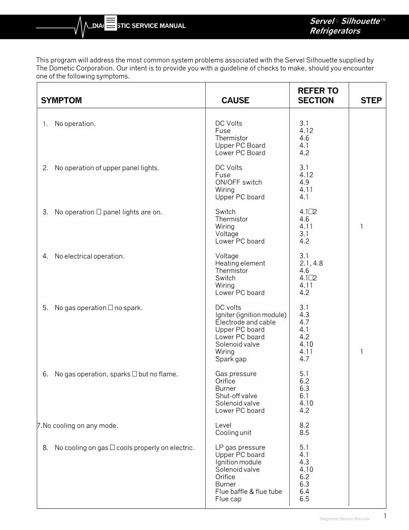
This program will address the most common system problems associated with the Servel Silhouette supplied byThe Dometic Corporation. Our intent is to provide you with a guideline of checks to make, should you encounterone of the following symptoms.
1. No operation.
2. No operation of upper panel lights.
3. No operation � panel lights are on.
4. No electrical operation.
5. No gas operation � no spark.
6. No gas operation, sparks � but no flame.
7.No cooling on any mode.
8. No cooling on gas � cools properly on electric.
REFER TOSYMPTOM CAUSE SECTION STEP
DC Volts 3.1Fuse 4.12Thermistor 4.6Upper PC Board 4.1Lower PC Board 4.2
DC Volts 3.1Fuse 4.12ON/OFF switch 4.9Wiring 4.11Upper PC board 4.1
Switch 4.1�2Thermistor 4.6Wiring 4.11 1Voltage 3.1Lower PC board 4.2
Voltage 3.1Heating element 2.1, 4.8Thermistor 4.6Switch 4.1�2Wiring 4.11Lower PC board 4.2
DC volts 3.1Igniter (ignition module) 4.3Electrode and cable 4.7Upper PC board 4.1Lower PC board 4.2Solenoid valve 4.10Wiring 4.11 1Spark gap 4.7
Gas pressure 5.1Orifice 6.2Burner 6.3Shut-off valve 6.1Solenoid valve 4.10Lower PC board 4.2
Level 8.2Cooling unit 8.5
LP gas pressure 5.1Upper PC board 4.1Ignition module 4.3Solenoid valve 4.10Orifice 6.2Burner 6.3Flue baffle & flue tube 6.4Flue cap 6.5
Diagnostic Service Manuals
2
DIAGNOSTIC SERVICE MANUALServel ® SilhouetteRefrigerators
TM
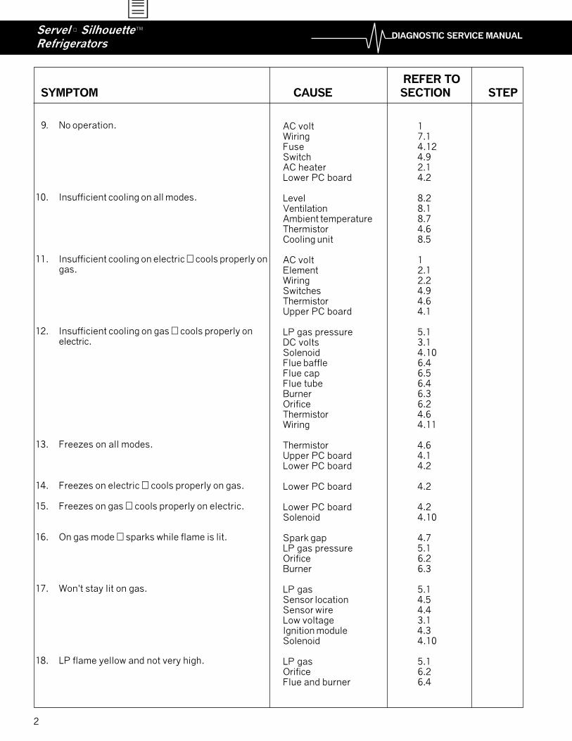
9. No operation.
10. Insufficient cooling on all modes.
11. Insufficient cooling on electric � cools properly ongas.
12. Insufficient cooling on gas � cools properly onelectric.
13. Freezes on all modes.
14. Freezes on electric � cools properly on gas.
15. Freezes on gas � cools properly on electric.
16. On gas mode � sparks while flame is lit.
17. Won't stay lit on gas.
18. LP flame yellow and not very high.
AC volt 1Wiring 7.1Fuse 4.12Switch 4.9AC heater 2.1Lower PC board 4.2
Level 8.2Ventilation 8.1Ambient temperature 8.7Thermistor 4.6Cooling unit 8.5
AC volt 1Element 2.1Wiring 2.2Switches 4.9Thermistor 4.6Upper PC board 4.1
LP gas pressure 5.1DC volts 3.1Solenoid 4.10Flue baffle 6.4Flue cap 6.5Flue tube 6.4Burner 6.3Orifice 6.2Thermistor 4.6Wiring 4.11
Thermistor 4.6Upper PC board 4.1Lower PC board 4.2
Lower PC board 4.2
Lower PC board 4.2Solenoid 4.10
Spark gap 4.7LP gas pressure 5.1Orifice 6.2Burner 6.3
LP gas 5.1Sensor location 4.5Sensor wire 4.4Low voltage 3.1Ignition module 4.3Solenoid 4.10
LP gas 5.1Orifice 6.2Flue and burner 6.4
REFER TOSYMPTOM CAUSE SECTION STEP
3
DIAGNOSTIC SERVICE MANUALServel ® SilhouetteRefrigerators
TM
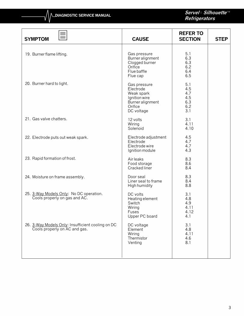
Gas pressure 5.1Burner alignment 6.3Clogged burner 6.3Orifice 6.2Flue baffle 6.4Flue cap 6.5
Gas pressure 5.1Electrode 4.5Weak spark 4.7Ignition wire 4.5Burner alignment 6.3Orifice 6.2DC voltage 3.1
12 volts 3.1Wiring 4.11Solenoid 4.10
Electrode adjustment 4.5Electrode 4.7Electrode wire 4.7Ignition module 4.3
Air leaks 8.3Food storage 8.6Cracked liner 8.4
Door seal 8.3Liner seal to frame 8.4High humidity 8.8
DC volts 3.1Heating element 4.8Switch 4.9Wiring 4.11Fuses 4.12Upper PC board 4.1
DC voltage 3.1Element 4.8Wiring 4.11Thermistor 4.6Venting 8.1
19. Burner flame lifting.
20. Burner hard to light.
21. Gas valve chatters.
22. Electrode puts out weak spark.
23. Rapid formation of frost.
24. Moisture on frame assembly.
25. 3-Way Models Only: No DC operation.Cools properly on gas and AC.
26. 3-Way Models Only: Insufficient cooling on DCCools properly on AC and gas.
REFER TOSYMPTOM CAUSE SECTION STEP
4
DIAGNOSTIC SERVICE MANUALServel ® SilhouetteRefrigerators
TM
SECTION 1
AC VOLTAGE REQUIREMENTS
This refrigerator is equipped with a three-prong plug forprotection against shock hazard and must be connectedinto a recognized three-prong receptacle.
The electrical cord should be routed in such a manneras to keep it away from the burner cover, flue pipe orother components that could damage the cord's insula-tion. Proper AC voltage for this style refrigerator is 120volts.
(132 volts max. � 100 volts min.)This voltage selection is made from the control panel onthe front of the refrigerator.
The incoming AC voltage is applied to terminals J9 andJ10 of the power supply module. (Lower PC board).From there it goes to the necessary areas via themodule board to perform the required function.
SECTION 2
AC COMPONENTS
USE EXTREME CAUTION WHEN WORKING ONANY AC ELECTRICAL COMPONENT OF THEREFRIGERATOR. DISCONNECT AC POWERSOURCE TO REFRIGERATOR BEFORE REPLAC-ING ANY ELECTRICAL COMPONENT. AC VOLT-AGES COULD CAUSE SEVERE INJURY ORDEATH.
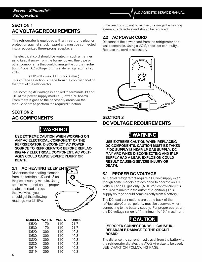
2.1 AC HEATING ELEMENTDisconnect the heating elementfrom the terminals J7 and J8 onthe power supply module. Usingan ohm meter set on the properscale and read acrossthe two wires, youshould get the followingreadings + or � 10%:
MODELS WATTS VOLTS OHMS
S520 170 110 71.7S530 170 110 71.7S620 300 110 40.3S630 300 110 40.3S820 300 110 40.3S830 300 110 40.3S619 300 110 40.3S819 300 110 40.3
If the readings do not fall within this range the heatingelement is defective and should be replaced.
2.2 AC POWER CORDDisconnect the power cord from the refrigerator andwall receptacle. Using a VOM, check for continuity.Replace the cord is necessary.
SECTION 3
DC VOLTAGE REQUIREMENTS
USE EXTREME CAUTION WHEN REPLACINGDC COMPONENTS. CAUTION MUST BE TAKENIF DC SUPPLY IS NEAR LP GAS SUPPLY. DCMAY ARC WHEN DISCONNECTING AND IF LPSUPPLY HAD A LEAK, EXPLOSION COULDRESULT CAUSING SEVERE INJURY ORDEATH.
3.1 PROPER DC VOLTAGEAll Servel refrigerators require a DC volt supply eventhough some models are designed to operate on 120volts AC and LP gas only. (A DC volt control circuit isrequired to maintain the automatic ignition.) Thissupply voltage should come directly from a battery.
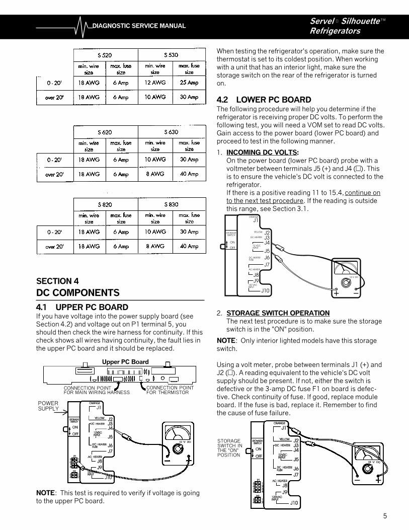
The DC lead connections are at the back of therefrigerator. Correct polarity must be observed whenconnecting to the battery supply. For proper operation,the DC voltage range is 11 minimum to 15.4 maximum.
IMPROPER CONNECTION WILL CAUSE IR-REPARABLE DAMAGE TO THE CIRCUITBOARD.
The distance the current must travel from the battery tothe refrigerator dictates the AWG wire size to be used.SEE CHART ON FOLLOWING PAGE.
5
DIAGNOSTIC SERVICE MANUALServel ® SilhouetteRefrigerators
TM
SECTION 4
DC COMPONENTS
4.1 UPPER PC BOARDIf you have voltage into the power supply board (seeSection 4.2) and voltage out on P1 terminal 5, youshould then check the wire harness for continuity. If thischeck shows all wires having continuity, the fault lies inthe upper PC board and it should be replaced.
NOTE: This test is required to verify if voltage is goingto the upper PC board.
When testing the refrigerator's operation, make sure thethermostat is set to its coldest position. When workingwith a unit that has an interior light, make sure thestorage switch on the rear of the refrigerator is turnedon.
4.2 LOWER PC BOARDThe following procedure will help you determine if therefrigerator is receiving proper DC volts. To perform thefollowing test, you will need a VOM set to read DC volts.Gain access to the power board (lower PC board) andproceed to test in the following manner.
1. INCOMING DC VOLTS:On the power board (lower PC board) probe with avoltmeter between terminals J5 (+) and J4 (�). Thisis to ensure the vehicle's DC volt is connected to therefrigerator.If there is a positive reading 11 to 15.4, continue onto the next test procedure. If the reading is outsidethis range, see Section 3.1.
2. STORAGE SWITCH OPERATIONThe next test procedure is to make sure the storageswitch is in the "ON" position.
NOTE: Only interior lighted models have this storageswitch.
Using a volt meter, probe between terminals J1 (+) andJ2 (�). A reading equivalent to the vehicle's DC voltsupply should be present. If not, either the switch isdefective or the 3-amp DC fuse F1 on board is defec-tive. Check continuity of fuse. If good, replace moduleboard. If the fuse is bad, replace it. Remember to findthe cause of fuse failure.
J1
J2J3J4
J5
J6
J7
J8J9
J10
ORANGE
YELLOW
DC HEATER
12 VDCINPUT
DC HEATERFUSE
AC HEATER
120 VACINPUT
ON
OFF
STORAGESWITCH
12 V. DC
Upper PC Board
CONNECTION POINTFOR THERMISTOR
CONNECTION POINTFOR MAIN WIRING HARNESS
POWERSUPPLY
STORAGESWITCH INTHE "ON"POSITION
6
DIAGNOSTIC SERVICE MANUALServel ® SilhouetteRefrigerators
TM
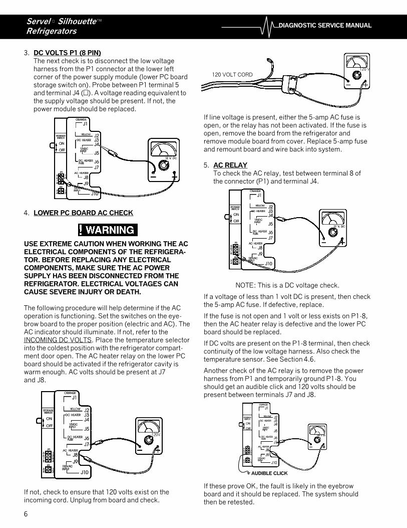
3. DC VOLTS P1 (8 PIN)The next check is to disconnect the low voltageharness from the P1 connector at the lower leftcorner of the power supply module (lower PC boardstorage switch on). Probe between P1 terminal 5and terminal J4 (�). A voltage reading equivalent tothe supply voltage should be present. If not, thepower module should be replaced.
4. LOWER PC BOARD AC CHECK
USE EXTREME CAUTION WHEN WORKING THE ACELECTRICAL COMPONENTS OF THE REFRIGERA-TOR. BEFORE REPLACING ANY ELECTRICALCOMPONENTS, MAKE SURE THE AC POWERSUPPLY HAS BEEN DISCONNECTED FROM THEREFRIGERATOR. ELECTRICAL VOLTAGES CANCAUSE SEVERE INJURY OR DEATH.
The following procedure will help determine if the ACoperation is functioning. Set the switches on the eye-brow board to the proper position (electric and AC). TheAC indicator should illuminate. If not, refer to theINCOMING DC VOLTS. Place the temperature selectorinto the coldest position with the refrigerator compart-ment door open. The AC heater relay on the lower PCboard should be activated if the refrigerator cavity iswarm enough. AC volts should be present at J7and J8.
If not, check to ensure that 120 volts exist on theincoming cord. Unplug from board and check.
If line voltage is present, either the 5-amp AC fuse isopen, or the relay has not been activated. If the fuse isopen, remove the board from the refrigerator andremove module board from cover. Replace 5-amp fuseand remount board and wire back into system.
5. AC RELAYTo check the AC relay, test between terminal 8 ofthe connector (P1) and terminal J4.
NOTE: This is a DC voltage check.
If a voltage of less than 1 volt DC is present, then checkthe 5-amp AC fuse. If defective, replace.
If the fuse is not open and 1 volt or less exists on P1-8,then the AC heater relay is defective and the lower PCboard should be replaced.
If DC volts are present on the P1-8 terminal, then checkcontinuity of the low voltage harness. Also check thetemperature sensor. See Section 4.6.
Another check of the AC relay is to remove the powerharness from P1 and temporarily ground P1-8. Youshould get an audible click and 120 volts should bepresent between terminals J7 and J8.
If these prove OK, the fault is likely in the eyebrowboard and it should be replaced. The system shouldthen be retested.
120V
120 V
120 VOLT CORD
AUDIBLE CLICK
7
DIAGNOSTIC SERVICE MANUALServel ® SilhouetteRefrigerators
TM
Thermistor
unpluggedfrom PCBoard
BLUE
GREEN
WHITE YEL
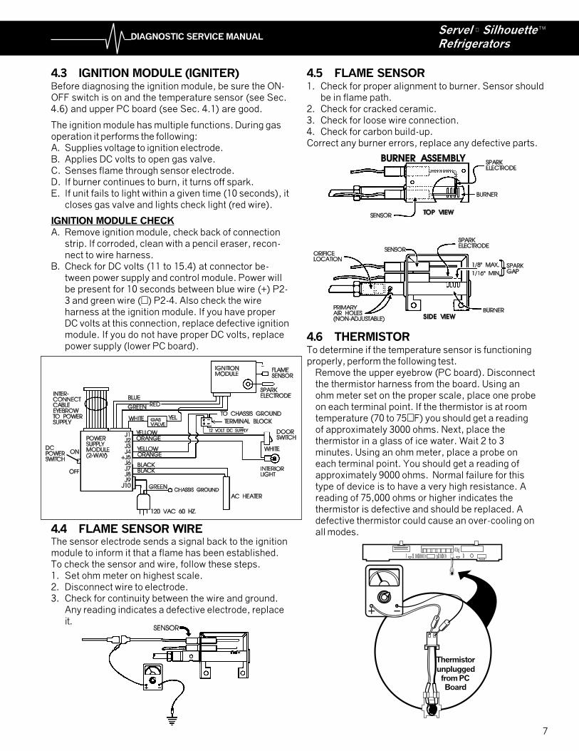
4.3 IGNITION MODULE (IGNITER)Before diagnosing the ignition module, be sure the ON-OFF switch is on and the temperature sensor (see Sec.4.6) and upper PC board (see Sec. 4.1) are good.
The ignition module has multiple functions. During gasoperation it performs the following:A. Supplies voltage to ignition electrode.B. Applies DC volts to open gas valve.C. Senses flame through sensor electrode.D. If burner continues to burn, it turns off spark.E. If unit fails to light within a given time (10 seconds), it
closes gas valve and lights check light (red wire).
IGNITION MODULE CHECKA. Remove ignition module, check back of connection
strip. If corroded, clean with a pencil eraser, recon-nect to wire harness.
B. Check for DC volts (11 to 15.4) at connector be-tween power supply and control module. Power willbe present for 10 seconds between blue wire (+) P2-3 and green wire (�) P2-4. Also check the wireharness at the ignition module. If you have properDC volts at this connection, replace defective ignitionmodule. If you do not have proper DC volts, replacepower supply (lower PC board).
4.4 FLAME SENSOR WIREThe sensor electrode sends a signal back to the ignitionmodule to inform it that a flame has been established.To check the sensor and wire, follow these steps.1. Set ohm meter on highest scale.2. Disconnect wire to electrode.3. Check for continuity between the wire and ground.
Any reading indicates a defective electrode, replaceit.
4.5 FLAME SENSOR1. Check for proper alignment to burner. Sensor should
be in flame path.2. Check for cracked ceramic.3. Check for loose wire connection.4. Check for carbon build-up.Correct any burner errors, replace any defective parts.
4.6 THERMISTORTo determine if the temperature sensor is functioningproperly, perform the following test.
Remove the upper eyebrow (PC board). Disconnectthe thermistor harness from the board. Using anohm meter set on the proper scale, place one probeon each terminal point. If the thermistor is at roomtemperature (70 to 75°F) you should get a readingof approximately 3000 ohms. Next, place thethermistor in a glass of ice water. Wait 2 to 3minutes. Using an ohm meter, place a probe oneach terminal point. You should get a reading ofapproximately 9000 ohms. Normal failure for thistype of device is to have a very high resistance. Areading of 75,000 ohms or higher indicates thethermistor is defective and should be replaced. Adefective thermistor could cause an over-cooling onall modes.
8
DIAGNOSTIC SERVICE MANUALServel ® SilhouetteRefrigerators
TM
4.7 SPARK ELECTRODE (SPARK GAPAND CABLE)
The function of this component is to supply a spark tothe burner to ignite the LP gas. Proper alignment of theelectrode to the burner 1/16" to 1/8" above the burner.
To check for a continuity reading, do the following test.1. Turn selector switch off.2. Disconnect the wire that goes to the electrode, from
the ignition module.3. With the volt ohm meter set on the proper scale,
check between the electrode wire and ground. Anyreading indicates a bad electrode. Replace theelectrode.
NOTE: A weakspark or anignition cycle ofless than 10secondsindicates avoltage supplyproblem to therefrigerator. Thisshould becorrected.
4.8 DC-VOLT HEATING ELEMENTDisconnect the heating element from J3 and J6 on thepower supply module. Using an ohm meter set on theRX1 scale, read across the two wires of the heatingelement. You should get the following reading: (Plus orminus 10%).
MODEL WATTS VOLTS OHMSS620 225 14 .87S830 225 14 .87S530 150 14 1.30
If the element does not fall within the above range, it isdefective and should bereplaced with a propersize Servel heatingelement. NOTE: If aprecise ohm meter isnot available, acontinuity reading willindicate an open orcomplete circuit. Ifthe test results showan open circuit,replace the element.
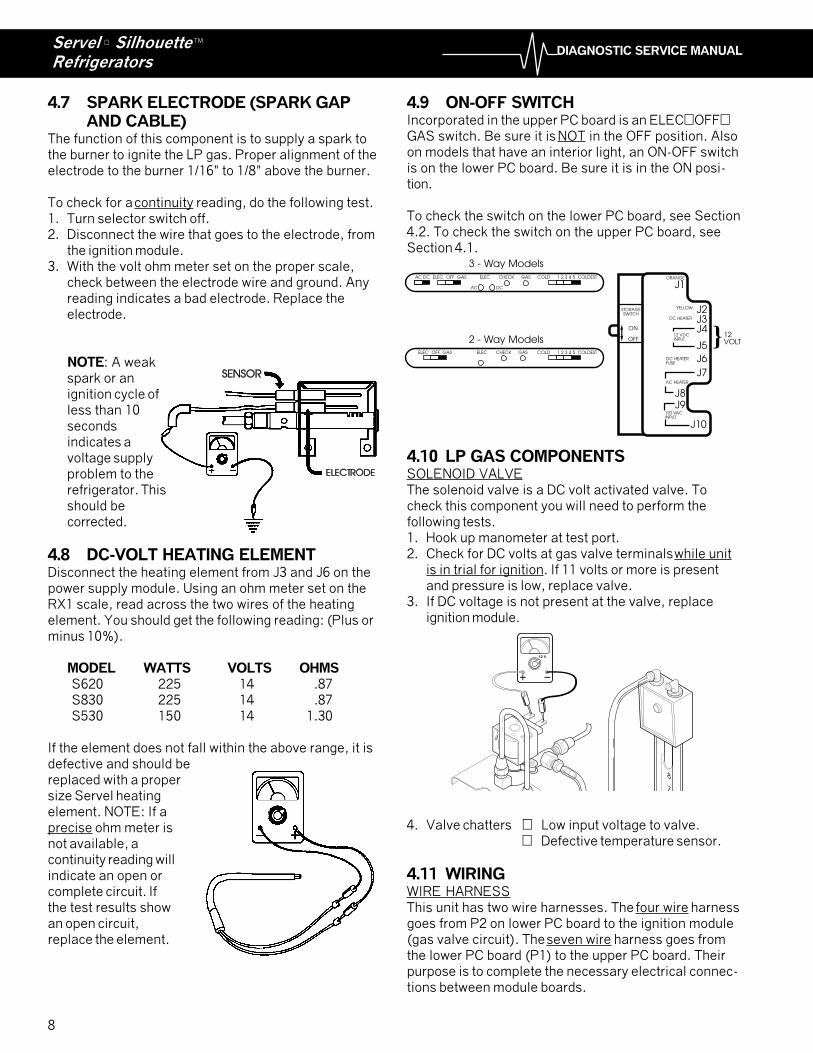
4.9 ON-OFF SWITCHIncorporated in the upper PC board is an ELEC�OFF�GAS switch. Be sure it is NOT in the OFF position. Alsoon models that have an interior light, an ON-OFF switchis on the lower PC board. Be sure it is in the ON posi-tion.
To check the switch on the lower PC board, see Section4.2. To check the switch on the upper PC board, seeSection 4.1.
4.10 LP GAS COMPONENTSSOLENOID VALVEThe solenoid valve is a DC volt activated valve. Tocheck this component you will need to perform thefollowing tests.1. Hook up manometer at test port.2. Check for DC volts at gas valve terminals while unit
is in trial for ignition. If 11 volts or more is presentand pressure is low, replace valve.
3. If DC voltage is not present at the valve, replaceignition module.
4. Valve chatters � Low input voltage to valve.� Defective temperature sensor.
4.11 WIRINGWIRE HARNESSThis unit has two wire harnesses. The four wire harnessgoes from P2 on lower PC board to the ignition module(gas valve circuit). The seven wire harness goes fromthe lower PC board (P1) to the upper PC board. Theirpurpose is to complete the necessary electrical connec-tions between module boards.
J1
J2J3J4
J5
J6
J7
J8J9
J10
ORANGE
YELLOW
DC HEATER
12 VDCINPUT
DC HEATERFUSE
AC HEATER
120 VACINPUT
ON
OFF
STORAGESWITCH
12VOLT
AC DC ELEC OFF GAS ELEC CHECK GAS COLD 1 2 3 4 5 COLDEST
AC DC
ELEC OFF GAS ELEC CHECK GAS COLD 1 2 3 4 5 COLDEST
3 - Way Models
2 - Way Models
8
7
12 V
9
DIAGNOSTIC SERVICE MANUALServel ® SilhouetteRefrigerators
TM
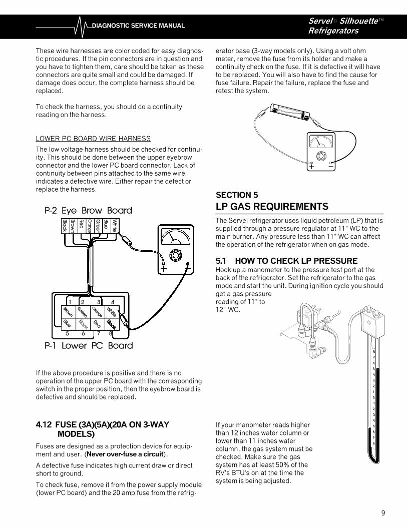
The low voltage harness should be checked for continu-ity. This should be done between the upper eyebrowconnector and the lower PC board connector. Lack ofcontinuity between pins attached to the same wireindicates a defective wire. Either repair the defect orreplace the harness.
If the above procedure is positive and there is nooperation of the upper PC board with the correspondingswitch in the proper position, then the eyebrow board isdefective and should be replaced.
4.12 FUSE (3A)(5A)(20A ON 3-WAY MODELS)
Fuses are designed as a protection device for equip-ment and user. (Never over-fuse a circuit).
A defective fuse indicates high current draw or directshort to ground.
To check fuse, remove it from the power supply module(lower PC board) and the 20 amp fuse from the refrig-
8
7
6
5
4
3
2
1
0
1
2
3
4
5
6
7
8
These wire harnesses are color coded for easy diagnos-tic procedures. If the pin connectors are in question andyou have to tighten them, care should be taken as theseconnectors are quite small and could be damaged. Ifdamage does occur, the complete harness should bereplaced.
To check the harness, you should do a continuityreading on the harness.
LOWER PC BOARD WIRE HARNESS
erator base (3-way models only). Using a volt ohmmeter, remove the fuse from its holder and make acontinuity check on the fuse. If it is defective it will haveto be replaced. You will also have to find the cause forfuse failure. Repair the failure, replace the fuse andretest the system.
SECTION 5
LP GAS REQUIREMENTS
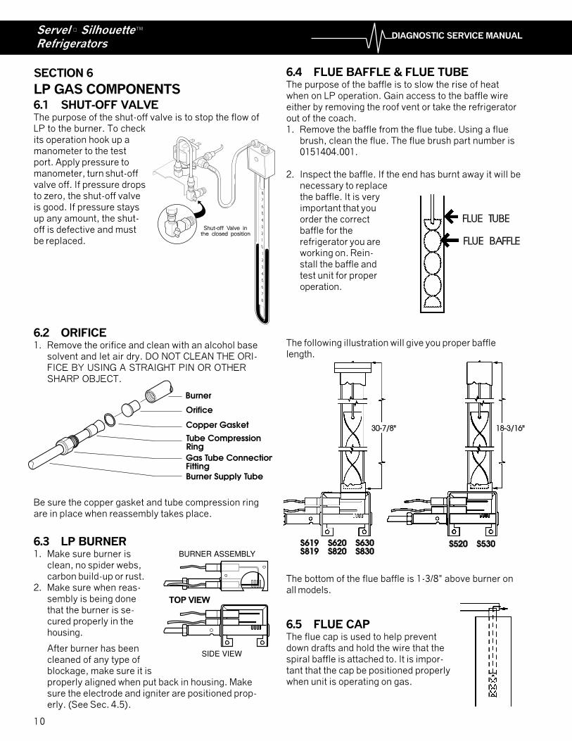
The Servel refrigerator uses liquid petroleum (LP) that issupplied through a pressure regulator at 11" WC to themain burner. Any pressure less than 11" WC can affectthe operation of the refrigerator when on gas mode.
5.1 HOW TO CHECK LP PRESSUREHook up a manometer to the pressure test port at theback of the refrigerator. Set the refrigerator to the gasmode and start the unit. During ignition cycle you shouldget a gas pressurereading of 11" to12" WC.
If your manometer reads higherthan 12 inches water column orlower than 11 inches watercolumn, the gas system must bechecked. Make sure the gassystem has at least 50% of theRV's BTU's on at the time thesystem is being adjusted.
10
DIAGNOSTIC SERVICE MANUALServel ® SilhouetteRefrigerators
TM
SECTION 6
LP GAS COMPONENTS6.1 SHUT-OFF VALVEThe purpose of the shut-off valve is to stop the flow ofLP to the burner. To checkits operation hook up amanometer to the testport. Apply pressure tomanometer, turn shut-offvalve off. If pressure dropsto zero, the shut-off valveis good. If pressure staysup any amount, the shut-off is defective and mustbe replaced.
6.2 ORIFICE1. Remove the orifice and clean with an alcohol base
solvent and let air dry. DO NOT CLEAN THE ORI-FICE BY USING A STRAIGHT PIN OR OTHERSHARP OBJECT.
Be sure the copper gasket and tube compression ringare in place when reassembly takes place.
6.3 LP BURNER1. Make sure burner is
clean, no spider webs,carbon build-up or rust.
2. Make sure when reas-sembly is being donethat the burner is se-cured properly in thehousing.
After burner has beencleaned of any type ofblockage, make sure it isproperly aligned when put back in housing. Makesure the electrode and igniter are positioned prop-erly. (See Sec. 4.5).
6.4 FLUE BAFFLE & FLUE TUBEThe purpose of the baffle is to slow the rise of heatwhen on LP operation. Gain access to the baffle wireeither by removing the roof vent or take the refrigeratorout of the coach.1. Remove the baffle from the flue tube. Using a flue
brush, clean the flue. The flue brush part number is0151404.001.
2. Inspect the baffle. If the end has burnt away it will benecessary to replacethe baffle. It is veryimportant that youorder the correctbaffle for therefrigerator you areworking on. Rein-stall the baffle andtest unit for properoperation.
The following illustration will give you proper bafflelength.
The bottom of the flue baffle is 1-3/8" above burner onall models.
6.5 FLUE CAPThe flue cap is used to help preventdown drafts and hold the wire that thespiral baffle is attached to. It is impor-tant that the cap be positioned properlywhen unit is operating on gas.
8
7
6
5
4
3
2
1
0
1
2
3
4
5
6
7
8
Burner Supply Tube
Gas Tube ConnectionFitting
Orifice
Burner
Copper Gasket
Tube CompressionRing
BURNER ASSEMBLY
SIDE VIEW
TOP VIEW
11
DIAGNOSTIC SERVICE MANUALServel ® SilhouetteRefrigerators
TM
SECTION 7WIRING
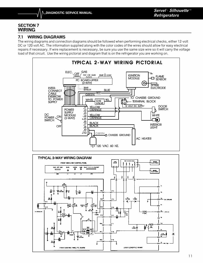
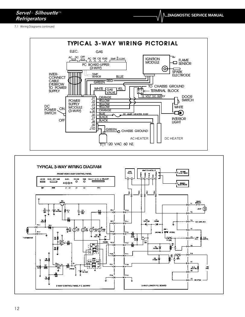
7.1 WIRING DIAGRAMSThe wiring diagrams and connection diagrams should be followed when performing electrical checks, either 12-voltDC or 120 volt AC. The information supplied along with the color codes of the wires should allow for easy electricalrepairs if necessary. If wire replacement is necessary, be sure you use the same size wire so it will carry the voltageload of that circuit. Use the wiring pictorial and diagram that is on the refrigerator you are working on.
12
DIAGNOSTIC SERVICE MANUALServel ® SilhouetteRefrigerators
TM
7.1 Wiring Diagrams continued
AC HEATER DC HEATER
13
DIAGNOSTIC SERVICE MANUALServel ® SilhouetteRefrigerators
TM
8.2 LEVELThe Servel refrigerators do not require critical levelingsuch as required by other absorption type refrigerators.Normal vehicle leveling to provide comfort for theoccupants is satisfactory for refrigerator operation. Thiswill be well within the operation limits of 3 degrees offlevel side-to-side, and 6 degrees off level front-to-backof the RV.
8.3 DOOR SEAL (AIR LEAKS)These gaskets are magnetic and when the door isclosed create a seal. The purpose is to keep warmroom air out of the refrigerator. To test a door gasketseal, place a dollar bill between the door gasket and themetal frame. Close the door, remove the dollar bill. Youshould encounter some resistance. Perform the sametest on all four sides of the refrigerator door. Any areathat shows little or no resistance indicates a defect inthe gasket. Warm the refrigerator and using a hairdryer, carefully warm the gasket in the area that did notmake a good seal. Close the door and let the sealreturn to normal room temperature. If this does notcorrect the poor seal, it will require replacement of thecomplete door.
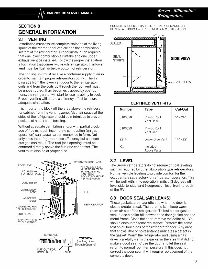
POCKETS SHOULD BE BAFFLED FOR PERFORMANCE EFFI-CIENCY, ALTHOUGH NOT REQUIRED FOR CERTIFICATION.
CERTIFIED VENT KITS
Number Type Cut-Out
3100528 Plastic Roof 5" x 24"Vent Base
3100529 Plastic RoofVent Cap
2214 Lower Side Vent 14" x 22"
Kit 1 IncludesAbove Parts
SIDE VIEW
SEALED
SEALSTRIPS
AIR FLOW
SECTION 8
GENERAL INFORMATION
8.1 VENTINGInstallation must assure complete isolation of the livingspace of the recreational vehicle and the combustionsystem of the refrigerator. Proper installation requiresthat one lower combustion air intake and one upperexhaust vent be installed. Follow the proper installationinformation that comes with each refrigerator. The lowervent must be flush or below bottom of refrigerator.
The cooling unit must receive a continual supply of air inorder to maintain proper refrigerator cooling. The airpassage from the lower vent door to the refrigeratorcoils and from the coils up through the roof vent mustbe unobstructed. If air becomes trapped by obstruc-tions, the refrigerator will start to lose its ability to cool.Proper venting will create a chimney effect to insureadequate circulation.
It is important to block off the area above the refrigera-tor cabinet from the venting zone. Also, air space at thesides of the refrigerator should be minimized to preventpockets of hot air from forming.
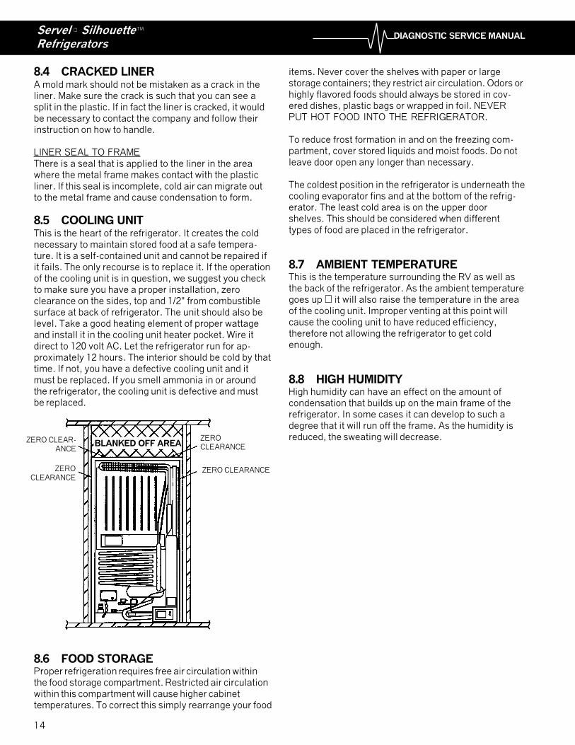
Without adequate ventilation and/or with partial block-age of flue exhaust, incomplete combustion (on gasoperation) can cause carbon monoxide to form. Notonly does the refrigerator lose efficiency but a poison-ous gas can result. The roof jack opening must becentered directly above the flue and condenser. Thevent must also be of proper size.
APPROVED ROOF JACK
AREAS a, b, c & dMUST BE BAFFLEDTO PREVENT HOTGAS FROMPOCKETING ABOVEREFRIGERATOR
FLUE
REFRIGERATOR
ROOF LEVEL
A � OPENINGFOR ROOF JACK
CONDENSER
VENTILATIONZONE
ABSORBERTUBES
L � OPENING FOR"0" CLEARANCE
FLOOR LEVEL
APPROVED FOR"0" CLEARANCE
b
ad
c
TOP VIEW(Looking Down
Through Opening)
CONDENSER
CUT-OUT FORROOF JACK FLUE
14
DIAGNOSTIC SERVICE MANUALServel ® SilhouetteRefrigerators
TM
8.4 CRACKED LINERA mold mark should not be mistaken as a crack in theliner. Make sure the crack is such that you can see asplit in the plastic. If in fact the liner is cracked, it wouldbe necessary to contact the company and follow theirinstruction on how to handle.
LINER SEAL TO FRAMEThere is a seal that is applied to the liner in the areawhere the metal frame makes contact with the plasticliner. If this seal is incomplete, cold air can migrate outto the metal frame and cause condensation to form.
8.5 COOLING UNITThis is the heart of the refrigerator. It creates the coldnecessary to maintain stored food at a safe tempera-ture. It is a self-contained unit and cannot be repaired ifit fails. The only recourse is to replace it. If the operationof the cooling unit is in question, we suggest you checkto make sure you have a proper installation, zeroclearance on the sides, top and 1/2" from combustiblesurface at back of refrigerator. The unit should also belevel. Take a good heating element of proper wattageand install it in the cooling unit heater pocket. Wire itdirect to 120 volt AC. Let the refrigerator run for ap-proximately 12 hours. The interior should be cold by thattime. If not, you have a defective cooling unit and itmust be replaced. If you smell ammonia in or aroundthe refrigerator, the cooling unit is defective and mustbe replaced.
items. Never cover the shelves with paper or largestorage containers; they restrict air circulation. Odors orhighly flavored foods should always be stored in cov-ered dishes, plastic bags or wrapped in foil. NEVERPUT HOT FOOD INTO THE REFRIGERATOR.
To reduce frost formation in and on the freezing com-partment, cover stored liquids and moist foods. Do notleave door open any longer than necessary.
The coldest position in the refrigerator is underneath thecooling evaporator fins and at the bottom of the refrig-erator. The least cold area is on the upper doorshelves. This should be considered when differenttypes of food are placed in the refrigerator.
8.7 AMBIENT TEMPERATUREThis is the temperature surrounding the RV as well asthe back of the refrigerator. As the ambient temperaturegoes up � it will also raise the temperature in the areaof the cooling unit. Improper venting at this point willcause the cooling unit to have reduced efficiency,therefore not allowing the refrigerator to get coldenough.
8.8 HIGH HUMIDITYHigh humidity can have an effect on the amount ofcondensation that builds up on the main frame of therefrigerator. In some cases it can develop to such adegree that it will run off the frame. As the humidity isreduced, the sweating will decrease.
8.6 FOOD STORAGEProper refrigeration requires free air circulation withinthe food storage compartment. Restricted air circulationwithin this compartment will cause higher cabinettemperatures. To correct this simply rearrange your food
ZERO CLEARANCE
ZERO CLEAR-ANCE
ZEROCLEARANCE
ZEROCLEARANCE
BLANKED OFF AREA
����������� ������ �������������� ��� ���������������
�������������� �� �� ����� �� � �� ����������������������������� �������������
� ��� ������������� ��������� ���� ���������������� ������������� ��� �� ��� �� �������� ����� ���������� ��������� ������������������������ ����� ��� �������������������������� ������� ������ ��� ��� ����������� !"��� � ������������������ ��� � !����������������#$%�&����� '����� ���
(����������������������� �������&� �� ����� ����������'�
��������������