senior project report - pmu · this project (design of aeroleaf wind turbine) is about designing...
TRANSCRIPT

College of Engineering
Department of Mechanical Engineering
Fall 2016-2017
Senior Project Report
Design of Aeroleaf Wind Turbine
Team Members
Student Name Student ID 1 Abdulkareem Abdullah A Alshammari 201200360
2 Mubarak Jazzaa N Alharbi 201201122
3 Abdulrahman Hassan D Alkaabi 201103011
4 Abdullah Ahmed Z Alghoneman 201103008
Project Advisors:
ADVISOR: CO- ADVISOR
Dr. Nader Nader Dr. Ali Chamkha
INSTRUCTOR: Dr. Nader Sawalhi
January 2017

2
Abstract
This project (Design of Aeroleaf Wind Turbine) is about designing and manufacturing a Vertical
Axis Wind Turbines VAWT to transfer the wind speed to a rotational motion using these turbines.
These turbines will be attached to a manufactured tree that will look like a modern design, which
can be installed in and around any public area such as parks, roads, public facilities, or business
offices. Aeroleaf Wind Turbines are designed to produce power up to 300 watts for each turbine.
This project presents a review on the performance of Savonius wind turbines. This type of turbine
is not commonly use and its applications for obtaining useful energy from air stream is still
considered as an alternative source. Low wind speed start-up, working with any wind direction, and
the less noise are some advantage of VAWT- Savonius model.
This project consists of three phases; designing, fabrication, and evaluating. An actual of gained
power is reported to be 31~35% relative to the theoretical gained power due to the instability and
inefficient of the wind speed.

3
Table of Contents
Abstract .............................................................................................................................................................. 2
Acknowledgment ................................................................................................................................................. 4
1. Introduction .................................................................................................................................................... 5
1.1 Project Definition .................................................................................................................................. 5
1.2 Project Objectives ................................................................................................................................. 5
1.3 Project Specification ............................................................................................................................. 6
1.4 Product Architecture and Components ................................................................................................. 6
1.5 Applications .......................................................................................................................................... 7
2. Literature Review ........................................................................................................................................... 8
2.1 Project background ............................................................................................................................... 8
2.2 Previous Work .................................................................................................................................... 11
2.3 Comparative Study ............................................................................................................................. 14
3. System Design .............................................................................................................................................. 16
3.1 Design Constraints .............................................................................................................................. 16
3.2 Design Methodology ........................................................................................................................... 17
3.3 Product Subsystems and Components ................................................................................................ 19
3.4 Implementation ................................................................................................................................... 27
4. System Testing and Analysis ......................................................................................................................... 33
4.1 Theoretical Wind TurbinePower Calculation ..................................................................................... 33
4.2 Experimental Readings ....................................................................................................................... 36
4.2 Discussion ........................................................................................................................................... 39
5. Project Management ..................................................................................................................................... 41
5.1 Project Plan ......................................................................................................................................... 42
5.2 Challenges and Decision Making ....................................................................................................... 44
5.3 Project Bill of Materials and Budget ................................................................................................... 44
6. Project Analysis ............................................................................................................................................ 46
6.1 Life-long Learning.................................................................................................................................. 46
6.2 Impact of Engineering Solutions ........................................................................................................... 46
6.3 Contemporary Issues Addressed ........................................................................................................... 48
7. Conclusions and Future Recommendations.................................................................................................. 49
7.1 Conclusions ......................................................................................................................................... 49
7.2 Future Recommendations ................................................................................................................... 49
References ............................................................................................................................................................ 52
Appendix A: Solidworks Drawings ...................................................................................................................... 53
Appendix B: Drawing & Designing Pictures ....................................................................................................... 63
Appendix C: Manufacturing Pictures ................................................................................................................... 67

4
Acknowledgment
This is the time where we reach the end of completing mechanical engineering program at PMU.
This senior project is a valuable chance where we implemented most of the skills and knowledge
that we gain throughout our studies.
The Aeroleaf Wind Turbine project team would like to thank the group advisor Dr. Nader Nader
and the group Co advisor Dr. Ali Chamkah for their supervision and instruction throughout the
semester. This thank is also extending to Dr. Nader Sawalhi for the support, guidance, leadership
and dedication.
We would like also to thank PMU facility and staff for giving us the education and skills required
to be at this level.

5
Chapter 1
INTRODUCTION
1.
1.1 PROJECT DEFINITION
This project is about designing and manufacturing an Aeroleaf Wind Turbine that can convert
wind by using Vertical Axis Wind Turbines (VAWT) to a useful energy.
The current power demanding in Saudi Arabia is very high compared to power consumption
world average, as reported by Arab news; Saudis consume three times more electricity than
the world average [1]. This high demanding should take the focus of attention in thinking in
different sources of energy.
One of the best sources of energy that can apply the concept of sustainability is renewable
energy such as sun, wind, and rivers. The positive point of wind energy is that unlike solar
energy that only used with sunlight, wind turbine can be useful all the 24 hours all the year.
Another concept of sustainability is the way that we should use in utilizing this renewable
energy efficiently, and environmentally friendly. This, in turn will eliminate the environment
hazard and improve Saudi Arabia communities’ health and life style.
Streets, public parks, schools, and public facilities are consider as main power consumers, these
consumers should be vulnerable to wind from time to time. The idea of this project is to convert
this wind by using Vertical Axis Wind Turbines (VAWT) to a useful energy by using it as a
power source that can serve these consumers.
1.2 PROJECT OBJECTIVES The main objective of this project is gaining power from wind. Therefore, this project is green
source of energy and has no effect on the life of earth. These wind energy turbines are small
and can produce up to 300 watts for each turbine.
Another objective of this project is gaining and exercising some engineering concepts such as:
Learn about wind energy and different ways of convert it to a useful power.
6
Learn the different between Vertical Axis Wind Turbines (VAWT) & Horizontal
Axis Wind Turbines (HAWT).
Learn the impact of energy & our rules as engineering students to provide
alternatives.
1.3 PROJECT SPECIFICATIONS
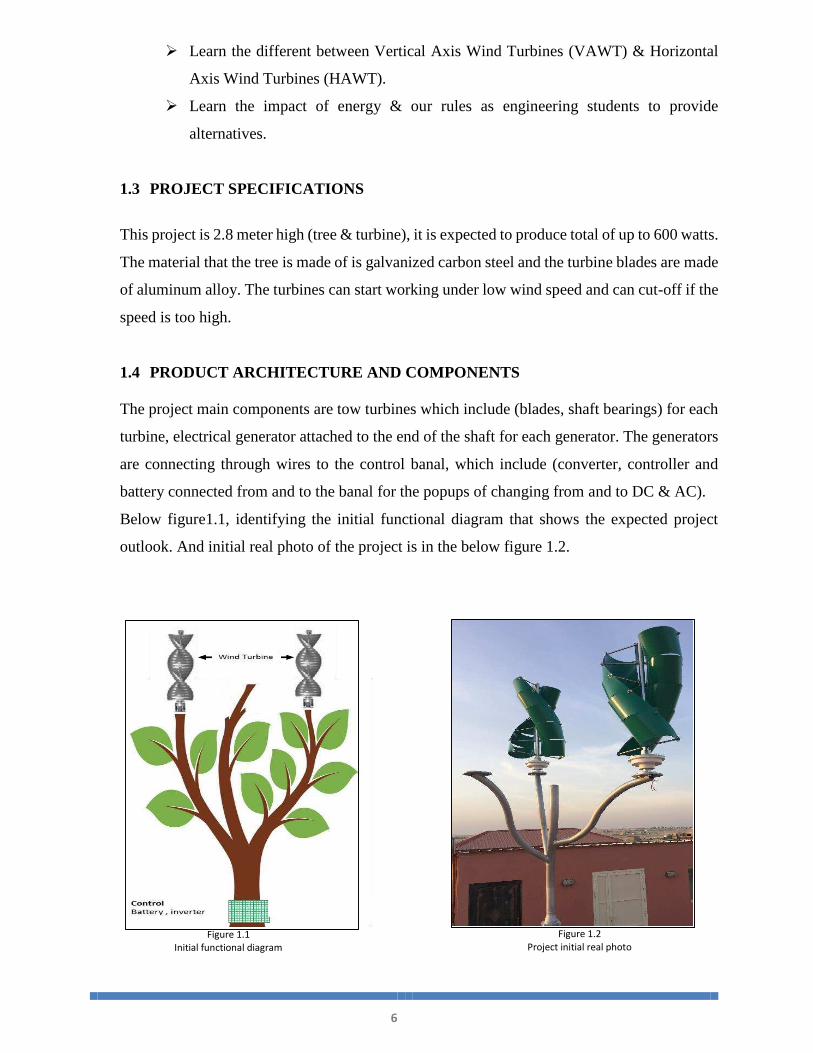
This project is 2.8 meter high (tree & turbine), it is expected to produce total of up to 600 watts.
The material that the tree is made of is galvanized carbon steel and the turbine blades are made
of aluminum alloy. The turbines can start working under low wind speed and can cut-off if the
speed is too high.
1.4 PRODUCT ARCHITECTURE AND COMPONENTS The project main components are tow turbines which include (blades, shaft bearings) for each
turbine, electrical generator attached to the end of the shaft for each generator. The generators
are connecting through wires to the control banal, which include (converter, controller and
battery connected from and to the banal for the popups of changing from and to DC & AC).
Below figure1.1, identifying the initial functional diagram that shows the expected project
outlook. And initial real photo of the project is in the below figure 1.2.
Figure 1.1
Initial functional diagram
Figure 1.2
Project initial real photo

7
1.5 APPLICATION This project idea is very simple, where it focuses on utilizing the wind energy by designing
and manufacturing two VAWT and attach them to a manufactured tree. This tree can be
installed across the public facilities. Facilities such as public parks, in the top of the stadiums
where wind is very high and around the stadiums, services’ buildings, and over the roads and
streets. It can also install in a simulated tree.

8
Chapter 2
LITERATURE REVIEW
2.
2.1 PROJECT BACKGROUND
Energy is the main economy base of any country. Sources of energy are not easy to have.
Having multiple sources of energy is extremely important to secure the basic living
requirement of any country. Utilizing the nature could help in converting some of the natural
phenomenons such as sun, wind, sea and oil into useful energy. This kind of energy called
renewable energy.
Science Daily Research Newspaper has defend renewable energy as “The most common
definition is that renewable energy is from an energy resource that is replaced rapidly by a
natural process such as power generated from the sun or from the wind.” [2].
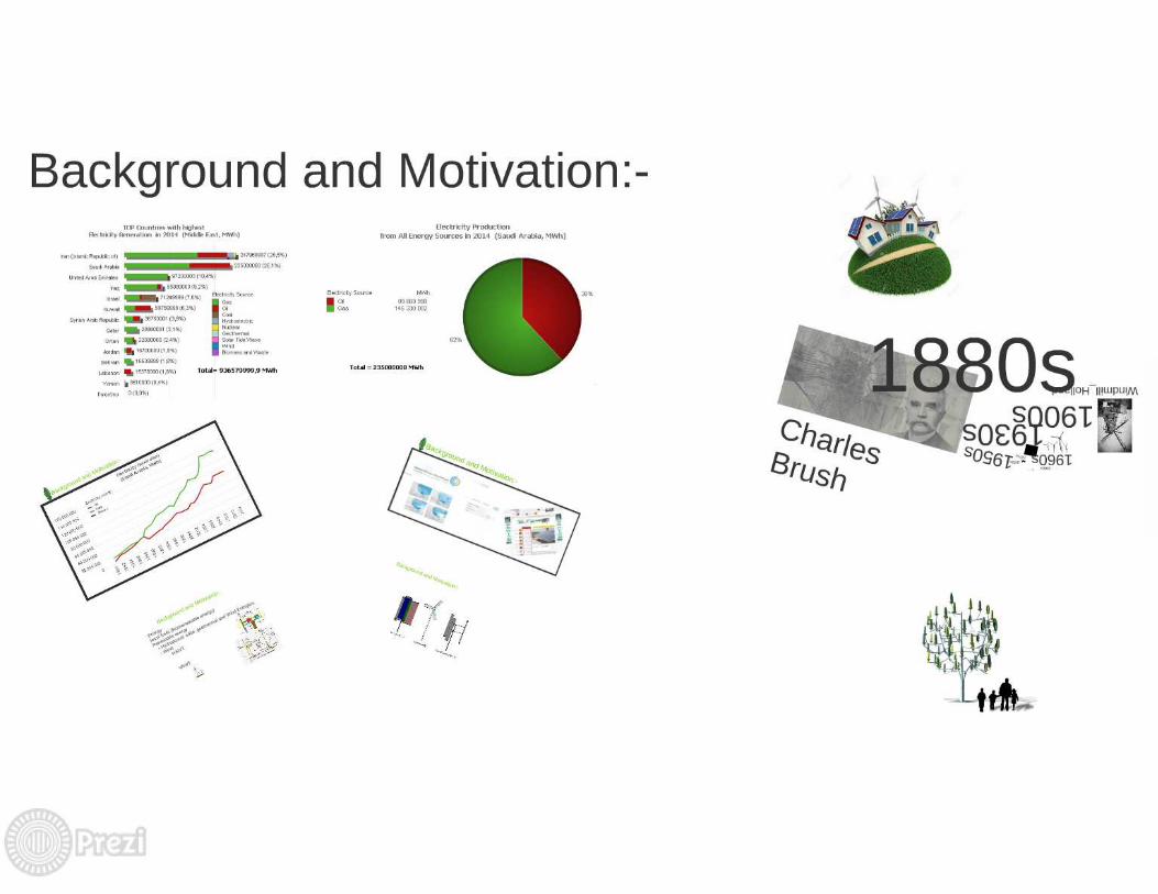
Recently, the increasing demand of renewable energy is very well noticed. According to a
report by the International Energy Agency, the increase of amount of electricity produced
from renewable sources increased from just over 13% in 2012 to 22% the following year.
They also predict that that figure should hit 26% by 2020 [3].
The traditional power plants in Saudi Arabia are mainly working on the fuel either gas or
oil which are not environmental friendly. EcoSpark environmental charity [4] has
considered oil power plants as one of the most contributors of environment pollution.
EcoSpark environmental charity has listed the below most significant environmental
impacts:
Oil causes air pollution and greenhouse gas emissions.
Oil uses large amounts of water, and creates water pollution and thermal discharge.
Oil creates hazardous sludge and solid waste.
Extracting and refining oil is environmentally destructive.
Transporting oil is risky and can harm the environment.
Oil is a non-renewable electricity source.
Such of the above environment affects lead us to think seriously about the renewable energy
sources, which will eliminate the environment hazard and improve health and life style.

9
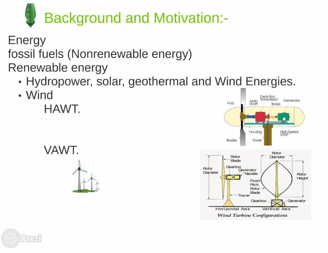
Wind energy is one of the most important energy sources. The concept of wind energy is
transforming the wind’s kinetic energy into mechanical energy. This energy drive blades
that turn generators that produce electricity. Our project is fitting with wind energy source.
The idea of this project is to convert the wind by using Vertical Axis Wind Turbines
(VAWT) into power.
They are two types of wind turbines, Horizontal Axis Wind Turbines (HAWT) as shown in
figure 2.1 that is more commonly used across the world and they are used as a power plants.
These kind of turbines are the most efficient of wind turbine. Cole Gustafson from Dakota
State University has mentioned the advantages and disadvantages of horizontal axis vs
vertical axis wind turbines, “In research studies evaluating wind turbine performance,
horizontal axis machines have been shown to be more efficient than vertical axis machines.
However, the blade span of horizontal wind turbines is larger than vertical axis machines
which limits placement confined spaces. Some people also find the large blade area of
horizontal axis machines objectionable” [5].
Figure 2.1
HAWT overview layout
http://lib.dr.iastate.edu/cgi/viewcontent.cgi?article=15875&context=rtd

10
The other type of wind turbine is the Vertical Axis Wind Turbines (VAWT) as shown in
figure 2.2. VAWT is the most popular of the turbines that people are using to make their
home a source of renewable energy.
VAWT is not as commonly used as the Horizontal Axis Wind Turbine. The reason behind
that is that VAWT is less efficient than HAWT when considered as a power plant generator.
However, for the small scales like homes, parks, or offices VAWT is more efficient.
“Vertical axis turbines are powered by wind coming from all 360 degrees, and even some
turbines are powered when the wind blows from top to bottom. Because of this versatility,
vertical axis wind turbines are thought to be ideal for installations where wind conditions
are not consistent, or due to public ordinances the turbine cannot be placed high enough to
benefit from steady wind.” [6]. Figure 2.3 shows the configuration of HAWT vs VAWT.
Figure 2.1
VAWT overview layout
http://lib.dr.iastate.edu/cgi/viewcontent.cgi?article=15875&context=rtd
Figure 2.3
Configuration of HAWT Vs VAWT
https://sci10sectionm.wordpress.com/2014/02

11
2.2 PREVIOUS WORK
There are two different styles of vertical wind turbines. One is the Savonius model, which
is our project is based on, and the other type is the Darrieus model. The first model looks
like a gallon drum that is been cut in half with the halves placed onto a rotating shaft. The
second model is smaller and looks much like an egg beater. Most of the wind turbines
being used today are the Savonius models.
Renewable Energy UK website provided some information about these two model. “A
Savonius is a type of vertical axis wind turbine (VAWT) generator invented in 1922 by
Sigurd Johannes Savonius from Finland though similar wind turbine designs had been
attempted in previous centuries."[7].
“A Darrieus is a type of vertical axis wind turbine (VAWT) generator. Unlike the
Savonius wind turbine, the Darrieus is a lift-type VAWT. Rather than collecting the wind
in cups dragging the turbine around, a Darrieus uses lift forces generated by the wind
hitting aerofoils to create rotation.” [8].
In Jun 2.15, International Research Journal of Engineering and Technology (IRJET) has
published a research titled “DESIGN, ANALYSIS AND FABRICATION OF SAVONIUS
VERTICAL AXIS WIND TURBINE” [9].
This research discussion was to showcase the efficiency of Savonius model in varying
wind conditions as compared to the traditional horizontal axis wind turbine. It evaluated
some observation that showed that at low angles of attack the lift force also contributes to
the overall torque generation. Thus, it can be concluded that the Savonius rotor is not a
solely drag-driven machine but a combination of a drag-driven and lift-driven device.
Therefore, it can go beyond the limit of Maximum power coefficient Cp established for
the purely drag-driven machines.
Some of this researched conclusions are that The vertical axis wind turbine is a small
power generating unit with the help of free source of wind energy. It is designed
under consideration of household use. Generally, At least 10% power of the consumption
can be fulfil by the Savonius model.
The research has also resulted that this turbine is generally suitable for 8 to 10m of height
above ground level. Because at ground level velocity of air is very less. And finally the
alternate option for turbine blade material is reinforced glass fiber because of its more
elastic nature but it is costlier than aluminum alloy.

12
To have the best efficiency of the power output from our turbine, the team has done some
brainstorming in what are the most significant factor that affect the turbine, the blade angle
was agreed to be the most significant one.
By doing some researches, we fined an article that focusing in the turbine blade angle.
A research article published by Advances in Mechanical Engineering (AIME) with a title
of “EFFECT OF THE BLADE ARC ANGLE ON THE PERFORMANCE OF A SEVONIUS
WIND TURBINE” [10].
This article is focusing on how to improve the efficiency of the turbine by selecting the best
blade angle.
The effect of the blade arc angle on the performance of a typical two-bladed Savonius wind
turbine is investigated with a transient computational fluid dynamics method. Simulations
were based on the Reynolds Averaged Navier–Stokes equations, and the renormalization
group turbulent model was utilized.
The numerical method was validated with existing experimental data.
The results of this article indicate that the turbine with a blade arc angle of 160° generates
the maximum power coefficient cp 0.2836, which is the highest that gain from the
experiment.
The article provided the below table 2.1, which shows the maximum coefficient of power
for different cases. Figure 2.1 shows the blade dynamic torque coefficient for different blade
arc angles
Table 2.1
Maximum coefficient of power for different cases [10]

13
Figure 2.4
Blade dynamic torque coefficient for different blade arc angles [10]

14
2.3 COMPARATIVE STUDY FOR AEROLEAF PROJECT
There was a student’s project which was about designing and evaluating of twisted savonius
wind turbine. This project was done under MEMORIAL UNIVERSITY [11]. This work’s goal
was to testing the self-starting of the turbine, also the work was targeting of the design can be
tested under harsh environmental conditions to assess longer-term reliability.
After fabrication and experiments under different wind conditions, this project presented results
as shown in the below table 2.2. The project conclusion was that the turbine has proved to be
self-starting under low wind speed.
Another student project we found was titled “design a Savonius Wind Turbine” from
Democritus University of Thrace [12]. The objective of this report is to study and manufacture
a wind turbine of vertical axis, Savonius type. In particular, what will be studied is which
geometrical design of the wings of the wind turbine is the most efficient, while taking into
account the cost, the elegance, the simplicity, the feasibility and the durability.
After fabrication and experiment, this project presented a result which shows the relation
between the wind velocity and the actual power of the wind turbine. The conclusion is that for
double wind velocity the power becomes 8 times more as shown in the below figure 2.5.
Table 2.2
Wind Speed Calibration Data

15
Another very important result is the Rotational Speed of the turbine depending on the wind
velocity which is shown to the below table 2.3 and figure 2.6.
This project presented a conclusions that the wind turbine which they constructed has several
advantages and uses. First of all, it can take advantage of every wind direction and begin the rotation
under very low wind powers. The noise it produces is very low compared to common wind turbines,
especially the horizontal axis one.
Figure 2.5
Actual Power according to the Wind Velocity
Table 2.3
Rotational speed for every Wind velocity
Figure 2.5
Rotational speed according to Wind velocity

16
Chapter 3
SYSTEM DESIGN
3.
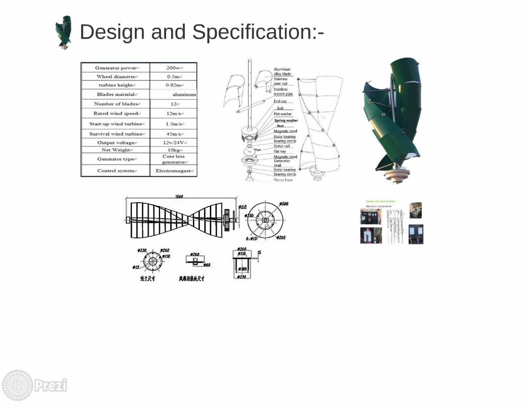
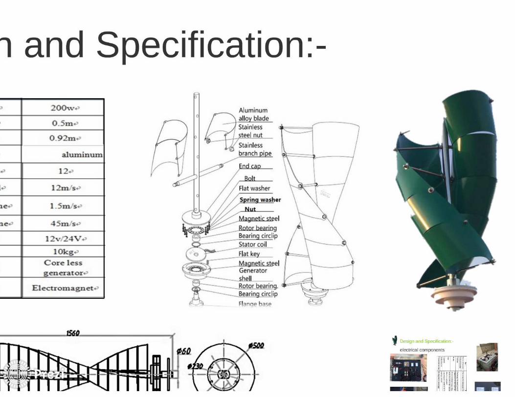
3.1 REQUIREMENTS, CONSTRAINTS AND SPECIFICATION
3.1.1 General specifications
Aeroleaf wind turbine is new way of producing energy form Vertical-axis method. This new
energy source is useful in the modern cities because of it is nice design and free noise. These
wind energy generators are. The Aeroleaf tree is designed hold two wind Savonius turbine,
which are small in size and can produce up to 300 watts.
The positive point of wind energy is that unlike solar energy that only can be used with
sunlight only. Wind energy can be useful all the 24 hours all the year. This project is green
source of energy and has no effect on the life of earth.
There are no effects on the environment at all. Moreover, it is reduce the CO2 and CO gases
that effect the environment in the earth. One of the biggest challenges is the social accept of
Aeroleaf Wind turbine.
3.1.2 Constraints and requirements
One of the most difficultly problem is the lack of necessary equipment needed for the
analysis and selection of materials accurately in the university. Also, in the market, I was
really difficult to find some of the needed materials.
These problems make the function of this project relying for some parts in design of
previous studies mentioned in chapter 2 by doing the reverse engineering.
Getting a sufficient wind, to analyze and test work. It was also the one of the berries that
we have encountered, because of the lack of wind in the area at that time, and the lack of
experience in aerodynamic science.
Beside the Lack of important resources, the lack of financial support was a major obstacle
in our way even though the budget was estimated

17
Although the existence of moral support from our professors, Lack of sufficient time was
a real challenge to show up the work as long as there was only one semester to complete
the senior project.
3.2 DESIGN METHODOLOGY
The methodology applied to this project can be divided into six phases. These phases are
information gathering, concept generation, model generation, model analysis and
refinement, concept selection, and verification, these phases are shown in figure 3.2.
Prior any appropriate solution can be developed, a thorough investigation has to be
conducted in order to find out what solutions have already been proposed (information
gathering).
Once these solutions have been analyzed and the team has an understanding of why the
respective solutions are not currently being implemented, a solution generation phase is
taking place. Here various solutions are presented and evaluated against criteria and
constraints (concept generation). Solution concepts are then modeling
The results of the models are then analyzed and the model, as well as solution parameters,
may be tweaked (model analysis and refinement).
Once the team has satisfactorily modeled all solution concepts of interest, the concept that
performs best analytically, in addition to meeting all criteria and constraints, is selected
Figure 3.2
Applied Phases of used Methodology

18
(concept selection). The analytical model may then be verified experimentally, using a small
scale modeling scheme or through a full scale experimental model.
The objective of this project is to design a vertical axis wind turbine (VAWT) that could
generate power under relatively low wind velocities. To accomplish this goal, the objectives
are to:
Analyze how different geometry of the wind turbines would affect the output power
of the wind turbine.
Vibrations analysis by testing how the vibrations caused from the rotations of the
wind turbines affect the structural integrity of various aspects buildings structures.
Compare the operation of turbines with respect to the numbers of attached plades.
To meet the above objectives, the tasks were to:
Conduct background research and analysis on wind turbine technology.
Design initially turbine blade for testing.
Design tree to hold these turbines.
Looking for power generator that has good efficiency with low startup speed.
Create experimental set up.
Manufacture parts and build model tree.
Develop future design recommendations.

19
3.3 Product Subsystems & Components
Vertical axis wind turbine VAWT are one whose axis of rotation is vertical with respect
to ground. Generally as shown in figure 3.3, the main components of this turbine are:
Blades
Shaft
Generator
.
Figure 3.3
Main components of VAWT
http://lib.dr.iastate.edu/cgi/viewcontent.cgi?article=15875&context=rtd

20
3.3.1 ROTOR BLADES
Savonius blades are a crucial and basic part of a wind turbine figure 3.4. They are mainly
made of aluminum, fiber glass or carbon fiber. We selected the aluminum alloy as
recommended in the study mentioned in chapter 2.2 because they provide batter strength to
weight ratio.
The design of the individual blades also affects the overall design of the rotor. Rotor blades
take the energy out of the wind; they capture the wind and convert its kinetic energy into
the rotation of the hub. The arc angle was selected based on the pervious study mentioned
in chapter 2.2, which recommended an angle of 160°
3.3.2 SHAFT
The shaft is the part that gets turned by the turbine blades. It in turn is connected to the
generator within the main housing.
A solidworks tools have been used in designing the blades and the shaft as shown in the
below figure 3.5
Figure 3.4
Turbine Blade Design

21
3.3.3 Radial & Thrust Bearings The bearing is integral part of the overall system. The lubricant and sealing elements
also play a crucial role. To enhance bearing effectiveness in the system, the right
type should be selected. However the procedure of the selection is a science but we
restricted on three simple steps:
1- Confirm operating conditions and operating environment.
2- Select bearing type and configuration.
3- Select bearing dimensions.
The correct amount of an appropriate lubricant must be present to reduce friction in
the bearing was consider. As long as the sealing elements are important because of
the environment surrounding our project and keep the lubricant in, and away from
the dust and contaminants. On another side, the low speed of the system was
consider too in the selection with axis and radial forces which is the weights of upper
system.
Figure 3.5
Solidworks sketch for Turbine Blade and Shaft Design

22
擦 珊姉餐珊残 噺 使司伺斬蚕算嗣 始餐賛酸嗣 抜 札司珊士餐嗣餐伺仔珊残 擦 司珊纂餐珊残 噺 仕 抜 磁 抜 匝司
As result we came up with two ball bearing 6004RS as shown in figure 3.6 where
can function as thrust and radial bearing (sealed and self-lubricant) and can carry the
Static Load Rating and Dynamic Load Rating 5 KN and 9 KN respectively and the
distance between the two bearings was based on as simulation Xpress done by
Central University Campus [13].
ITME.no. DESCRIPTION
3 and 8 ball bearing_6004 RS
Figure 3.6
Selected Bearing Details
Equation 3.1
Equation 3.2

23
3.3.4 Electrical Parts
The turbines are connected to electrical parts in order to get the required power. These parts
are as shown in the below table 3.1.
Part Function
Electrical Generator Converting the rotating speed to an electrical
Turbine Controller
Combiner Combining the earned power from each turbine to one output power
Battery Charged electrically to provide a static potential for power or
released electrical charge when needed.
Fuse an electrical device that can interrupt the flow of electrical current
when it is overloaded
Converter Converting DC current to AC current
Turbine Sensors Braking overload
Consumption reading Reading battery percentage
3.3.5 GENERATOR
The conversion of rotational mechanical energy to electrical energy is performed by
generator. Different types of generator have been used in wind energy system over the years.
For large, commercial size horizontal-axis wind turbines, the generator is mounted in a
nacelle at the top of a tower, behind the hub of the turbine rotor. Typically wind turbines
generate electricity through asynchronous machines that are directly connected with the
electricity grid. Usually the rotational speed of the wind turbine is slower than the equivalent
rotation speed of the electrical network - typical rotation speeds for wind generators are 5-
20 rpm while a directly connected machine will have an electrical speed between 750-3600
rpm. Therefore, a gearbox is inserted between the rotor hub and the generator. This also
reduces the generator cost and weight.
The generator used for the prototype is the Low RPM permanent magnet DC generator
created by Wind Stream Power and is a 12-volt step generator. The generator has an internal
resistance of 21Ω.
Table 3.1
Electrical Parts

24
The current generator can only operate continuously with a current of 1.5 amperes and at a
max of 1.5 minutes with a current of 3 amperes the below figures 3.6 and 3.7 are explaining
the generator parts.
ITME.no. DESCRIPTION 2 End Cap 3 radial ball bearing_68_am 6 Magnetic Steel 7 Shell 8 thrust ball bearing3_68_am 9 Shaft 10 Coil
Figure 3.6
Generator parts
Figure 3.7
Generator parts with description

25
3.3.6 Battery
The battery that we used in our project is The Long WPL150-12N rechargeable power guard
sealed lead acid battery as shown in the below figure 3.8, and table 3.2
Brand Name Long
Item Weight 45.5kg
Capacity 150Ah
Dimensions 19.02 x 6.7 x 9.5
Maximum Discharge Current For (5 Seconds) 1500A
Maximum Charging Current For (5 Seconds) 45A
Design Life 12 Years
Figure 3.8
Long WPL150-12N Battery
Table 3.2
Long WPL150-12N Battery Details

26
3.3.7 Bottom Pipe
Considering the total weight of the so far construction and the desirable design of the wind
turbine three support bases will be used. These three levels are connected and supported,
the material we used for the bases was metal as shown in simulation figure 3.9.
Model name: Bottom Pipe Current Configuration: Default
Solid Bodies Document Name and
Reference Treated As Volumetric Properties Document Path/Date
Modified Cut-Extrude8
Solid Body
Mass:12.342 kg Volume:0.00156823 m^3 Density:7870 kg/m^3 Weight:120.951 N
Model Reference Properties Components
Name: Galvanized Steel Model type: Linear Elastic
Isotropic Default failure criterion:
Unknown
Yield strength: 2.03943e+008 N/m2 Tensile strength: 3.56901e+008 N/m^2 Elastic modulus: 2e+011 N/m^2 Poisson's ratio: 0.29 Mass density: 7870 kg/m^3
SolidBody 1(Cut-Extrude8)(Bottom Pipe)
Figure 3.9
Simulation of Bottom Pipe

27
3.4 Implementation
3.4.1 Turbine design & sketch
After compiling background research, we started the planning for the project. We reached
a point where we started the initial drawings of the design. Basically, we drew the overall
project outlook, which is a tree, turbine(s), electrical generator, and light as shown in figures
3.10, 3.11.
Figure 3.10
Schematic Diagram
Figure 3.11
Visual Schematic Diagram

28
As shown in figure 3.11, the turbine design was made using the SolidWorks tools which we used
at the beginning to identify the design initial parameters for better understanding.
Figure 3.11
Turbine SolidWork sketch

29
3.4.2 Designing tree Model
At this stage, we reached to a point where we need to start planning for designing the tree.
This planning starting from defining the high and width of the tree, which we agreed leader
to be 2.8 meter high to achieve as much wind as possible and 2 width.
A goal for defining a tree branches was to have the most popular design and material that
would be able to provide realistic results. Initially, we tried to use aluminum material for
the tree branches. But, this marital will not hold the turbines easily, and if it did it will not
hold them for long time.
We finally came to the conclusion that a carbon steel galvanizing materials (Pipe, flanges
& blade) for the tree would satisfy our requirements. Figure 12.13 shows initial tree design.
And figure 3.13 shows the solidworks drawing.
Figure 3.12
Initial Tree Design

30
A carbon steel galvanizing pipes that we used to build the tree are shown in Figure 3.10.
Figure 3.13
Carbon Steel Galvanizing Pipes
Figure 3.13
solidworks drawing

31
3.4.3 Manufacturing of turbine blades and rod.
The vertical shaft that held the turbine was manufactured out of quarter inch stainless steel
with press fits designed to attach to the generator. It also had two set screws which kept the
shaft connected to both instruments as well as a set screw in the middle to lock turbine in
place.
The blade manufacturing was assigned to a workshop plant in Jubal using the solid work
drawings and the given requirements and specifications.
The top and bottom pieces were cut out of 3/8th inch acrylic and then glued together.
The metal rods used to lock the adjustable blade to the top and bottom pieces were glued
together with epoxy.
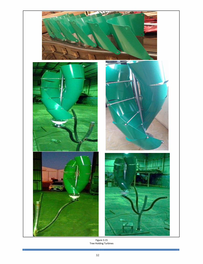
In the below figures 3.14 & 3.15 pictures of the tree and blades manufacturing respectively.
Figure 3.14
Tree Branches Manufacturing
32
Figure 3.15
Tree Holding Turbines

33
Chapter 4 4.
SYSTEM TESTING AND ANALYSIS
4.1 THEORETICAL WIND TURBINE POWER CALCULATION
Wind Power depends on:
amount of air (volume)
speed of air (velocity)
mass of air (density)
Kinetic Energy definition:
皐撮 噺 層匝 抜 仕 抜 士匝
Where: 仕 Mass 士 velocity
Since Power is Energy per time, we can formulate equation 4.1 to be 鶏 噺 怠態 抜 兼岌 抜 懸態 兼岌 噺 鳥陳鳥痛
Fluid mechanics gives mass flow rate (density 抜 volume flux): 鳥陳鳥痛 噺 貢 抜 畦 抜 懸
Thus, power of the wind is 鶏 噺 怠態 抜 貢 抜 畦 抜 懸戴
Equation 4.1

34
Taking in consideration the turbine Power coefficient, power in the wind is calculated using this
formula:
皿 噺 層匝 抜 持 抜 冊 抜 士惣 抜 察使
Where: 鶏 Power in watts
貢 Air density “At sea level ‘air density’ is approximately 1.2 賃直陳典
畦 Turbine Area in 兼態, which can be calculated from the length of turbine blades.
畦 噺 劇憲堅決件券結 月件訣月建 抜 建憲堅決件券結 拳件穴建月 See figure 4.1. in our project the
turbine high is 0.9m and width is 1.25m. Therefore, area is 畦 噺 月 抜 拳 畦 噺 どひ 抜 なにの 噺ななにの兼 懸戴: wind speed, which is the velocity of the wind in 陳鎚 .
系喧 Power coefficient, usually varies according to wind turbine design, ranging between 0.05
and 0.45. In this case, referring to the previously mentioned study in chapter 2, we are taking
0.2836 based on the selected angle 160°.
The only variable in this equation is the wind speed. Table 4.1 and graph 4.1 are reported the
Theoretical gained power at different wind speeds.
Equation 4.2

35
Theoretical Gained Power Calculation
Density
ʌ
A =h*w= 1.125m Wind Wpeed
V
Power
coefficient
Cp
Power
P
Power (2)
Turbines
P h=0.9m w=1.25m
1.2 1.125
1
0.2836
0 0
2 2 3
3 5 10
4 12 25
5 24 48
6 41 83
7 66 131
Table 4.1
Theoretical Gained Power Calculation
Figure 4.1
Theoretical Turbine Gained Power vs. Wind Speed

36
4.2 EXPERIMENTAL READINGS
After designing the components and structures desired for testing power output for wind
turbine designs and the structures desired to be tested, we created the experimental set-ups
required to test the prototypes and structures.
In order to determine the effectiveness of the products that were manufactured, we performed
tests to evaluate them. The test set up was in Half Moon (open area). We also tested the
power output of the turbine blades and evaluated how the vibrations from the turbine affect
the stress and strain on a tree structure.
Two experiments have been conducted; the procedure of calculating the power is counting
the voltage & current that feeding the battery. The power gained can be calculated using the
below equation. 鶏 噺 荊撃
Where: 荊 Current in Ampere 撃 voltage
Below are the results that we got from the experiments. Table 4.2 and figure 4.2 are for
experiment# 1, table 4.3 and figure 4.3 are for experiment# 2
4.2.1 Experiment# 1
Equation 4.3
Table 4.2
Experiment# 1 Reading
TimeWind Speed
m/S
Voltage(V)
Current(I)
Power(Watt)
Power (2)
Trubines(Watt)
21:00 0.7 8.6 0.05 0 1
18:00 1.6 10.6 0.15 2 3
15:00 3.4 12.3 0.24 3 6
12:00 4.3 13.7 0.43 6 12
9:00 5.2 14.2 0.52 7 15
Experimental Readings
Experiment# 1Normal weather
* Sorted by increasing in wind speed

37
4.2.2 Experiment# 2
Experimental Readings
Experiment# 2 Windy Day
Time Wind
Speed m/S
Voltage (V)
Current (I)
Power (Watt)
Power (2)
Turbines
(Watt)
21:00 6.2 15.8 0.51 8 16
18:00 6.6 16.5 0.57 9 19
15:00 7.1 17.2 0.84 14 29
12:00 7.5 17.7 1.2 21 42
9:00 8.4 18.4 1.9 35 70
8 914
21
35
1619
29
42
70
4
14
24
34
44
54
64
74
5.5 6.5 7.5 8.5
Po
we
r (W
att
s)
Wind Speed (m/s)
Experimental Turbines Gained Power Vs Wind SpeedExperiment# 2
One
Turbine
Two (2)
Turbines
Table 4.3
Experiment# 2 Reading
Figure 4.2
Experiment# 1 Readings
Figure 4.3
Experiment# 2 Readings

38
4.2.3 Theoretical comparing to Experimental Gained Power Calculation.
Table 4.4
Theoretical Vs Experimental Reading
Figure 4.4
Theoretical Vs Experimental Reading
39
4.3 DISCUSSION
As a result, This studies (experimentally and theoretically) present a review on the performance
of Savonius wind turbines and show the gap between the actual and ideal output power, where
a several factors have affected clearly on the actual performance, these factors are due to
external factors, lack of resources, process, geometrically, or due to human error. These factor
resulted in drop of 31~ 35% between the theoretical and experiment results.
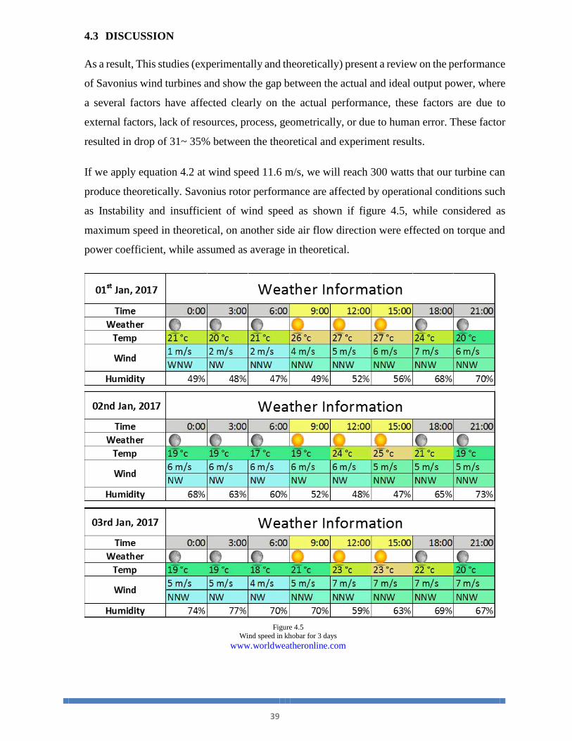
If we apply equation 4.2 at wind speed 11.6 m/s, we will reach 300 watts that our turbine can
produce theoretically. Savonius rotor performance are affected by operational conditions such
as Instability and insufficient of wind speed as shown if figure 4.5, while considered as
maximum speed in theoretical, on another side air flow direction were effected on torque and
power coefficient, while assumed as average in theoretical.
Figure 4.5 Wind speed in khobar for 3 days
www.worldweatheronline.com
40
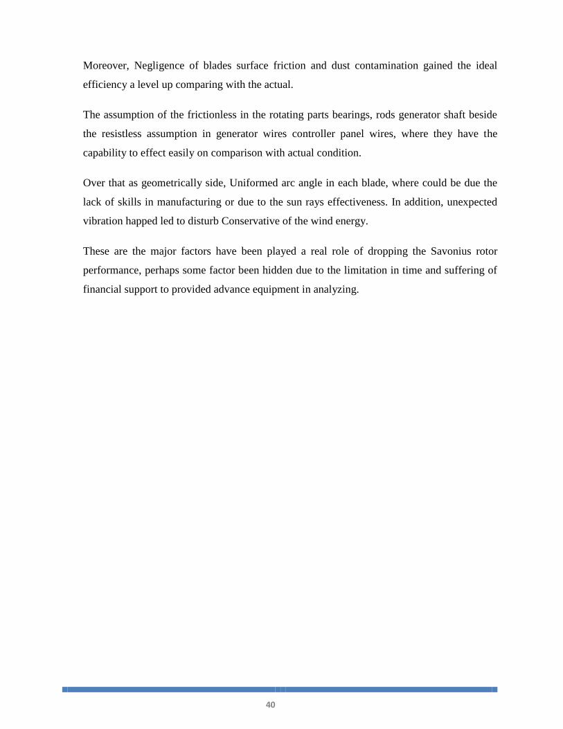
Moreover, Negligence of blades surface friction and dust contamination gained the ideal
efficiency a level up comparing with the actual.
The assumption of the frictionless in the rotating parts bearings, rods generator shaft beside
the resistless assumption in generator wires controller panel wires, where they have the
capability to effect easily on comparison with actual condition.
Over that as geometrically side, Uniformed arc angle in each blade, where could be due the
lack of skills in manufacturing or due to the sun rays effectiveness. In addition, unexpected
vibration happed led to disturb Conservative of the wind energy.
These are the major factors have been played a real role of dropping the Savonius rotor
performance, perhaps some factor been hidden due to the limitation in time and suffering of
financial support to provided advance equipment in analyzing.

41
Chapter 5 5.
PROJECT MANAGEMENT 1.
Our belief in the professionalism and workmanship at work put us in a position where we work
in the concept of project management. Project management is the process and activity of
planning, organizing, motivating, and controlling resources, procedures and protocols to
achieve our goals.
A project is a temporary endeavor designed to produce a unique product, service or result with
a defined beginning and end (usually time-constrained, and often constrained by funding or
deliverables), undertaken to meet unique goals and objectives, typically to bring about
beneficial change or added value.
Like any other project, the senior student project described in this report needed attention in
terms of project management. Achieving minimum goals set by the university (client in project
management terminology) regarding the senior projects was a challenge in presence of certain
constraints such as time, scope and budget. Furthermore, achieving the best quality was simply
not possible in the absence of a proper equipment and the required laboratories and tolls that
needed for such projects.
On the contrary, to the above-mentioned importance of applying project management strategy
in the discussed project, it is also evident that the project had a limited scope and resources to
be managed. Therefore, a simple and traditional strategy, as outlined in the following block
diagram, was adopted to make sure the project is successfully completed within the specified
time and budget frames.

42
5.1 PROJECT PLAN The project planning has started when the projects were assigned to the groups. Team leader
also nominated and assigned by the group members. We start planning for work distribution
to meet the millstones that been given by the instructor.
The below figure shows a timeline that the team developed to plan carefully for the required
tasks and meet the deadlines.
5.1.1 Contribution of Team Members
Contribution of the team members of this project was proactive, the team work was going
smoothly over the semester achieving the milestone one by one. All the group members
were participating in all of this project steps,
This project steps are:
Planning Research and Analysis
Designing and Manufacturing Bi-weekly reports
Weekly meetings Final report writing
Mid and Final presentation Final demonstration
Figure 5.2
Project Timeline

43
Designing and manufacturing was totally a full group work. However, writing the report
was assigned as the below table:
Final Report Writing Work Distribution
Task Assigned member
Assigned proofreading member
Introduction Project Definition AHK MZH Project Objectives MZH AHK Applications AAS AZG
Literature Review Project background AZG AAS Previous Work AHK MZH Comparative Study MZH AHK
System Design
Design Constraints AAS AZG Design Methodology AZG AAS Product Subsystems & Components
AHK MZH
Implementation MZH AHK System Testing &
Analysis Testing AAS AZG Analysis AZG AAS
Project Management
Project Plan AHK MZH Contribution of Team Members
MZH AHK
Challenges & Decision Making
AAS AZG
Project Bill of Materials & Budget
AZG AAS
Project Analysis
Life-long Learning AHK MZH Impact of Engineering Solutions
MZH AHK
Contemporary Issues Addressed
AAS AZG
Conclusions & Future
Recommendations
Conclusions AZG AAS Future Recommendations AHK MZH
MZH Mubarak Alharbi AHK Abdulrahman Alkabi AAS Abdulkarim Alshamari AZG Abdullah Alghoniman
Table 5.1
Final Report Writing Work Distribution

44
5.2 CHALLENGES & DECISION MAKING
In our project we planned to use plastic material with shaft, tree and turbine blades and due the
difficult to find plastic manufacturers and also, due to the high coast for plastic to fabricate this
design we decided to change it to metal. However, we believe if could be made from plastic it
will be more flexible to move it to different places. Also, the design of branches would be
easier to carry plastic turbine.
5.3 BROJECT BILL OF MATERIALS & BUDGET
5.3.1 Bill of materials (BOM)
A bill of materials (BOM) is a hierarchical list of components used in an assembly. The bill
of materials is used chiefly for cost estimates, but is also used for inventory control and
tracking where parts are used.
# Parts Spec. Quantity Unit Price SR
Total Price/part SR
1 Flange bolts M12*45 4 8 32
2 Plain washer D12.2 8 24 192
3 Spring washer D12.2 4 30 120
4 Nuts M8 48 6 288 5 Connecting rod M8 6 18 108
6 Screw M8 12 24 288 7 Nuts M12 4 8 32 8 Blades Aluminum 36 100 3600 9 Electrical Gen. Wind Stream RBM 3 600 1800 10 Battery Lead-acid 1 1600 1600 11 Elect. Combiner - 1 120 120 12 Turbine Controller - 2 80 160 13 Turbine Sensor - 2 150 300 14 Consuming reader - 1 110 110 15 Converter - 1 80 80 16 Pipe Carbon Steel 8 150 1200
Total Prices 10,030
Table 5.2
Bill of Materials (BOM)

45
5.3.2 Budget
This section contain the full budget that were spend in this project from the beginning all
the way to the demonstration day.
Below Table 5.3 is the budget breakdown.
# Item Cost SR
1 Marital 10030
2 Manufacturing 4000
3 Final Report
(3) Spiral Copies 360
4 Final Report
(3) Leather Copies 540
5 Poster 280
6 Brochures 150
Total Cost 15,360
Table 5.3
Project budget breakdown

46
Chapter 6
6.
PROJECT ANALYSIS
6.1 LIFE-LONG LEARNING This experience that the team have went through is very valuable in term of engineering sense,
skills, and knowledge. Guidance from PMU instructor and advisors were very valuable and
help achieving the main goal of this course. Teamwork and leadership were applied through
this experience which add good management skills to the team members.
Fabrication and manufacturing was not easy where we had to change the manufacturing
workshop several time and that is due to the inefficient tools that they are using, choosing
better workshop with high stander will cost more money .We were facing a lot of difficulties
getting the required equipment and materials with the right dimensions. Testing, analysis, and
evaluating our result was difficult specially when come to calculation the experimental results.
The assigned time to finish such senior project was not enough, which add more pressure to
the team members taking in consideration the others courses the team members are taking in
the same semester.
6.2 IMPACT OF ENGINEERING SOLUTIONS
6.2.1 Renewable Energy
Energy resources are getting more difficult to get. With the increasing of the population,
and high demand of the power, and taking in consideration the current situation of the oil
prices and it reliability. Saudi Arabia has to start as soon as possible implementing the use
of renewable energy. Wind energy can be very useful for this purpose. This project and
research as any other similar studies are convincing that wind energy can help a lot the
country supplying power with these renewable energy which can be costly at the beginning,
but it will be the most reliability solution that can apply the concept of sustainability.

47
6.2.2 Economy
As the largest economy by far in the Middle East, Saudi Arabia is also the largest potential
RE market in the region. The country developed a massive renewable energy program that
aimed to install 54 GW by 2032; this program, however, has been delayed and likely will
not be implemented as originally announced.
Nevertheless, Saudi Aramco and Saudi Electricity Company are both going ahead with their
own initiatives and joint plans to develop renewable energy in Saudi Arabia in the short and
medium term. Expect significant growth in the coming years for both solar and wind, as the
Kingdom strives for a sustainable energy mix to preserve a large share of extracted oil for
future export.
Within GCC, Saudi Arabia is the most promising market for wind. With a surface area of
2.25 million km² and a GDP of USD 730B, Saudi Arabia is the largest country and economy
in the GCC.
Saudi Arabia accounts for half of GCC’s power demand (273 TWh in 2012) and will be the
region’s primary wind market in the short term (100 out of the region’s 200 MW
installedcapacity by 2015). As a result of the immense power demand, an additional 47 GW
and approximately 29 GW of replacement capacity are needed by 2020.
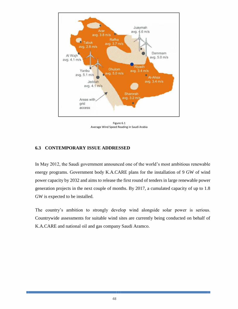
Saudi Arabia provides various suitable sites for large-scale onshore wind generation. The
first criterion for site suitability is a minimum wind speed of around 3.7 m/s at a height of
10 m in order for wind generation to be competitive with the LCOE of oil-fired electricity
generation. Secondly, suitable wind power sites must also have adequate access to the
electricity network.
The majority of sites fulfilling these requirements are situated along the two coastlines, for
example, Yanbu in the West and Juaymah and Dammam/Al Khobar/Dhahran in the East
(Figure 6.1). With existing wind measurements limited to location of meteorological
stations only, additional attractive sites can be expected in unchartered regions.
48
6.3 CONTEMPORARY ISSUE ADDRESSED
In May 2012, the Saudi government announced one of the world’s most ambitious renewable
energy programs. Government body K.A.CARE plans for the installation of 9 GW of wind
power capacity by 2032 and aims to release the first round of tenders in large renewable power
generation projects in the next couple of months. By 2017, a cumulated capacity of up to 1.8
GW is expected to be installed.
The country’s ambition to strongly develop wind alongside solar power is serious.
Countrywide assessments for suitable wind sites are currently being conducted on behalf of
K.A.CARE and national oil and gas company Saudi Aramco.
Figure 6.1
Average Wind Speed Reading in Saudi Arabia

49
Chapter 7
7. 2.
CONCLUSIONS AND FUTURE RECOMMENDATIONS
7.1 CONCLUSION From our research we were able to come up with many important conclusions and suggestions
which will profit the future advancement of individual vertical pivot wind turbines. We could
outline a VAWT framework that enhanced power yield when contrasted with the past projects.
From our results we were able to recommend new design aspects to improve the system and
efficiency.
Inefficient wind speed was the huge impact getting the required power output, minimum speed
of 12 m/s is required to have acceptable output power taking in consideration 31~35% of
efficiency between theoretical and experimental results.
Even though we were able to make this design of Vertical Axis Wind Turbine but there is a
never ending process to always improve upon inventions and new designs. Wind turbines are
a start for society to lessen the damage done to the earth by not using energy sources that
produces pollution. Hopefully the project could propel research and testing on VAWT
frameworks and give knowledge for different gatherings to finish additionally testing and
enhance productivity and execution of vertical pivot wind turbines.
7.2 FUTURE RECOMMENDATIONS
Using the data received we made recommendations for future studies regarding the potential
of commercial tree wind turbines. These recommendations will hopefully aid in the
development of a technology that would allow green energy to reduce energy costs in the
average household and better the environment. Future tests could help determine the feasibility
of houses, neighborhoods, or cities powered by wind turbines and being able to run off of
renewable energy.
The turbine performance testing and results from the research in this venture demonstrated that
the split Savonius is the best plan that has been tried to this point at WPI. The reason is because
of the expansive surface range of the split Savonius which empowers it to catch most maximum
amounts of wind. We trust that further research ought to be finished with different Savonius

50
plans in view of this reality. The Savonius turbine outlines are basic and modest to make, and
are additionally not incredibly influenced by turbulence in the wind.
Another suggestion to improve the Savonius design in our opinion would be to create a more
aerodynamic backing to the Savonius cusp. This design would reduce the energy it requires to
spin with the wind. this will allow the Savonius to rotate into the wind more efficiently, thus
increasing the rate of revolution. While we do not expect this to make a significant difference,
our testing demonstrates that even small differences in wind speeds lead to significantly
improved power output.
To gain the best power gain in the concept of green energy, we strongly recommend having
some solar panels attached to the tree. These panels will add more power and they are easy to
install and connected to the electrical components that are already added to the system. Below
figures 7.1, 7.2 & 7.3 are some recommended design sketches having the solar panels.
Figure 7.1
Recommended Design Sketch

51
Figure 7.2
Recommended Design Sketch
Figure 7.3
Recommended Design Sketch

52
REFERENCES
[1] ABDUL GHAFOUR , P. (2014, June & july). KSA power consumption 3 times world average. Arab News.
Retrieved from http://www.arabnews.com/news/598481
[2] Renewable energy. (n.d.). Science Daily Research Newspaper . Retrieved from
https://www.sciencedaily.com/terms/renewable_energy.htm
[3] Renewable energy. (n.d.). International Energy Agency. Retrieved from
https://www.iea.org/about/faqs/renewableenergy/
[4] Oil Power. (n.d.). Retrieved from EcoSpark /www.ecospark.ca/wattwize/students/oil
[5] Cole,G. (n.d.). Energy. Retrieved from https://www.ag.ndsu.edu/energy/energyeconomics/faqs-1/what-are-the-
advantages-and-disadvantages-of-horizontal-axis-vs-verticalaxis-wind-turbines
[6] Vertical Axis Wind Turbines vs Horizontal Axis Wind Turbines. (n.d.). Retrieved October/November, 2009, from
http://www.windpowerengineering.com/construction/verticalaxis-wind-turbines-vs-horizontal-axis-wind-turbines/
[7] Savonius Wind Turbines. (n.d.). Retrieved from Renewable Energy UK
http://www.reuk.co.uk/wordpress/wind/savonius-wind-turbines/
[8] Darrieus Wind Turbines. (n.d.). n.d.). Retrieved from Renewable Energy UK
http://www.reuk.co.uk/wordpress/wind/darrieus-wind-turbines/
[9] Ashwin , D., & Vaibhav, B., Prof. (2015). DESIGN, ANALYSIS AND FABRICATION OF SAVONIUS
VERTICAL AXIS WIND TURBINE. International Research Journal of Engineering and Technology (IRJET).
Retrieved from https://www.irjet.net/archives/V2/i3/Irjet-v2i3331.pdf
[10] EFFECT OF THE BLADE ARC ANGLE ON THE PERFORMANCE OF A SEVONIUS WIND TURBINE.
(2015). SAGE journals. Retrieved from Advances in Mechanical Engineering
http://journals.sagepub.com/doi/pdf/10.1177/1687814015584247
[11] Duffett, I., Perry, J., Stockwood, B., & Wiseman, J. (2009). DESIGN AND EVALUATION OF TWISTED
SAVONIUS WIND TURBINE. MEMORIAL UNIVERSITY. Retrieved from http://www.mun.ca/ Vertical Wind
Energy Engineering
[12] & [13] Babalas, D., Bafounis, E., Divanis, I., Psomas, E., & Simadopoulos, A. (2015). Design of a Savonius
Wind Turbine. Democritus University of Thrace. Retrieved from http://duth.gr/index.en.shtml Department of
Production Engineering & Management

53
Appendix A
Solidworks Drawings

54

55

56

57

58

59

60

61

62

63
Appendix B
Drawing & Designing Pictures
Turbine sketch

64
Schematic Diagram

65
Visual Schematic Diagram
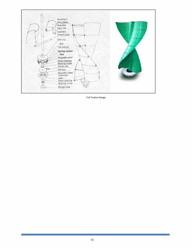
66
Full Turbine Design

67
Appendix C
Manufacturing Pictures
Tree Branches Manufacturing

68
Tree Holding Turbines

69
Generator