pantalla de soldadura welding helmet … · • regulador del tiempo de retardo. existen tres...
TRANSCRIPT
MI03078-01
PANTALLA DE SOLDADURA WELDING HELMET
OPTIMATIC 500
LEA CUIDADOSAMENTE TODO EL MANUAL ANTES DE PONER EL PRODUCTO EN MARCHA READ ENTIRE MANUAL CAREFFULLY BEFORE OPERATING THE PRODUCT
MI03078-01
1. ANTES DE SOLDAR
• La máscara de soldadura OPTIMATIC 500 está dotada de un filtro de oscurecimiento automático,
por lo que pueden usarse sin apenas necesidad de ajustes previos. Antes de empezar a soldar, ajuste simplemente la cinta de la máscara a su cabeza y seleccione el tono de filtro correcto (el nivel de protección) que necesita para la aplicación que va a llevar a cabo.
• Compruebe que las lentes del visor están limpias y que no hay restos de suciedad taponando ninguno de los cuatro sensores situados en la parte delantera del cartucho del filtro. Compruebe también las lentes delanteras internas del visor y el marco-soporte de las lentes delanteras para asegurarse que están bien sujetas.
• Revise todas las piezas de accionamiento para detectar posibles indicios de desgaste o daños. Para minimizar el riesgo de lesiones graves, sustituya inmediatamente cualquier pieza que le parezca desgastada o deteriorada antes de volver a usar el casco.
• Antes de usar esta máscara, compruebe siempre que no permite la entrada a ninguna filtración de luz.
• Seleccione el tono de filtro que necesita, girando el regulador de tono. Consulte siempre la Tabla Orientativa sobre niveles de protección para elegir el nivel adecuado al tipo de soldadura que desea realizar.
• Ajuste la cinta elástica a su cabeza de manera que la máscara descanse sobre la parte inferior de la cabeza y lo más cerca posible de la cara. Ajuste el ángulo del casco cuando esté bajado, girando la arandela ajustable de tope.
2. SELECCION DEL NUMERO DE OSCURECIMINETO
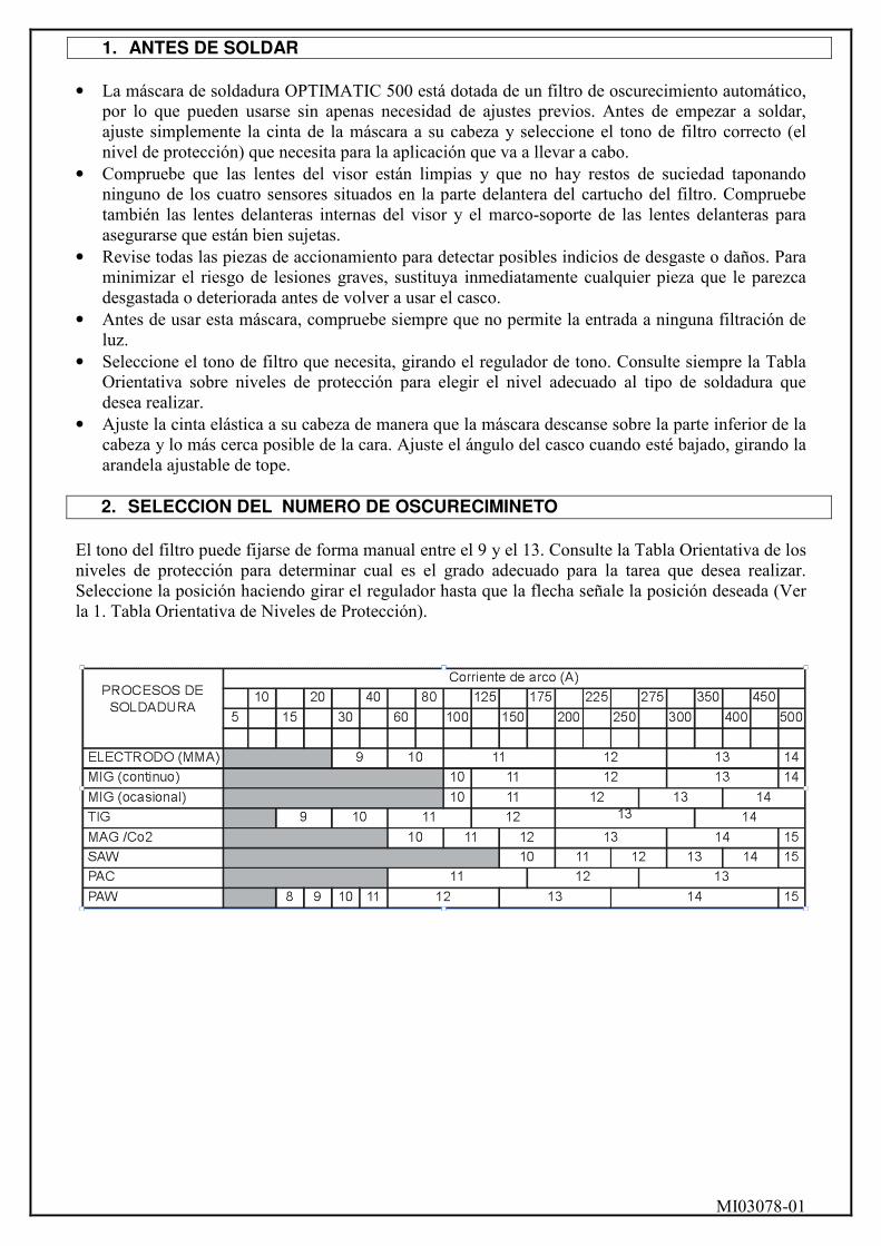
El tono del filtro puede fijarse de forma manual entre el 9 y el 13. Consulte la Tabla Orientativa de los niveles de protección para determinar cual es el grado adecuado para la tarea que desea realizar. Seleccione la posición haciendo girar el regulador hasta que la flecha señale la posición deseada (Ver la 1. Tabla Orientativa de Niveles de Protección).
MI03078-01
3. ESPECIFICACIONES
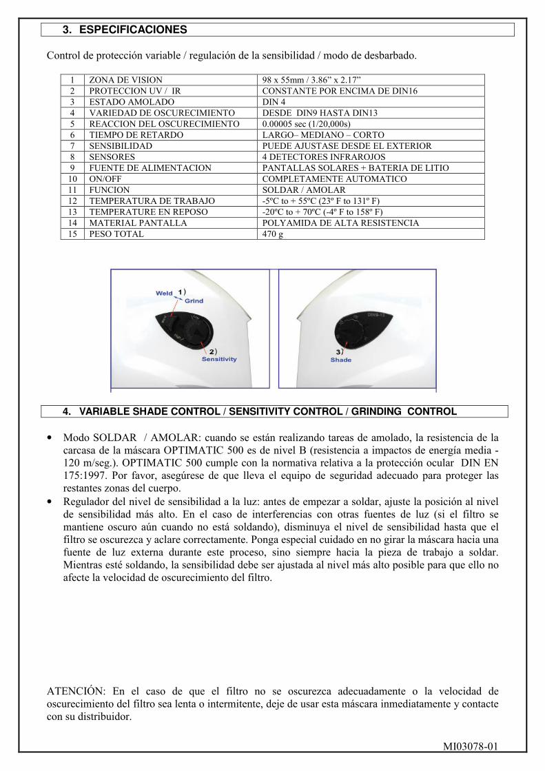
Control de protección variable / regulación de la sensibilidad / modo de desbarbado.
1 ZONA DE VISION 98 x 55mm / 3.86” x 2.17” 2 PROTECCION UV / IR CONSTANTE POR ENCIMA DE DIN16 3 ESTADO AMOLADO DIN 4 4 VARIEDAD DE OSCURECIMIENTO DESDE DIN9 HASTA DIN13 5 REACCION DEL OSCURECIMIENTO 0.00005 sec (1/20,000s) 6 TIEMPO DE RETARDO LARGO– MEDIANO – CORTO 7 SENSIBILIDAD PUEDE AJUSTASE DESDE EL EXTERIOR 8 SENSORES 4 DETECTORES INFRAROJOS 9 FUENTE DE ALIMENTACION PANTALLAS SOLARES + BATERIA DE LITIO 10 ON/OFF COMPLETAMENTE AUTOMATICO 11 FUNCION SOLDAR / AMOLAR 12 TEMPERATURA DE TRABAJO -5ºC to + 55ºC (23º F to 131º F) 13 TEMPERATURE EN REPOSO -20ºC to + 70ºC (-4º F to 158º F) 14 MATERIAL PANTALLA POLYAMIDA DE ALTA RESISTENCIA 15 PESO TOTAL 470 g
4. VARIABLE SHADE CONTROL / SENSITIVITY CONTROL / GRINDING CONTROL • Modo SOLDAR / AMOLAR: cuando se están realizando tareas de amolado, la resistencia de la
carcasa de la máscara OPTIMATIC 500 es de nivel B (resistencia a impactos de energía media - 120 m/seg.). OPTIMATIC 500 cumple con la normativa relativa a la protección ocular DIN EN 175:1997. Por favor, asegúrese de que lleva el equipo de seguridad adecuado para proteger las restantes zonas del cuerpo.
• Regulador del nivel de sensibilidad a la luz: antes de empezar a soldar, ajuste la posición al nivel de sensibilidad más alto. En el caso de interferencias con otras fuentes de luz (si el filtro se mantiene oscuro aún cuando no está soldando), disminuya el nivel de sensibilidad hasta que el filtro se oscurezca y aclare correctamente. Ponga especial cuidado en no girar la máscara hacia una fuente de luz externa durante este proceso, sino siempre hacia la pieza de trabajo a soldar. Mientras esté soldando, la sensibilidad debe ser ajustada al nivel más alto posible para que ello no afecte la velocidad de oscurecimiento del filtro.
ATENCIÓN: En el caso de que el filtro no se oscurezca adecuadamente o la velocidad de oscurecimiento del filtro sea lenta o intermitente, deje de usar esta máscara inmediatamente y contacte con su distribuidor.
MI03078-01
• Regulador de protección u oscurecimiento – para elegir el tono del filtro, antes de empezar a
soldar haga girar la perilla hasta la posición adecuada para realizar una comprobación inicial. Consulte la Tabla Orientativa sobre los niveles de protección para seleccionar el tono correcto, en función de la intensidad de la corriente que requerirá su proceso de soldadura. En el caso de que el tono del filtro sea demasiado oscuro o demasiado claro, ajuste ligeramente la perilla a la posición correcta, hasta que los ojos puedan mirar la pieza de soldar sin deslumbrarse. Debe tener en cuenta que un ajuste inadecuado del nivel de protección de la máscara de soldadura puede provocar graves daños oculares si la exposición tiene una duración prolongada, por lo que es muy importante que siga atentamente los pasos especificados.
ATENCIÓN: Si el filtro no se oscurece o no lo hace lo suficiente, o si la velocidad de oscurecimiento es demasiado lenta o intermitente, intente encontrar las causas antes de usar de nuevo la máscara. En el caso de que no consiga solucionar el problema, deje de usar la máscara inmediatamente y contacte con su distribuidor.
5. TIEMPO DE RETARDO / TEST
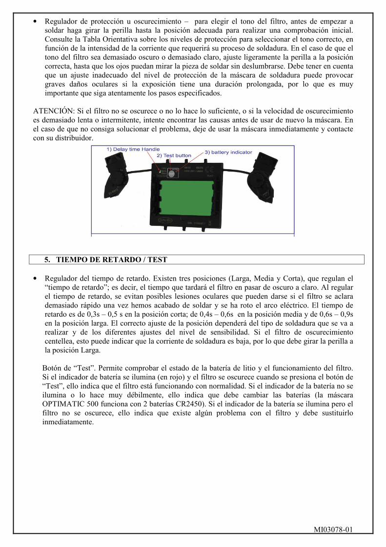
• Regulador del tiempo de retardo. Existen tres posiciones (Larga, Media y Corta), que regulan el
“tiempo de retardo”; es decir, el tiempo que tardará el filtro en pasar de oscuro a claro. Al regular el tiempo de retardo, se evitan posibles lesiones oculares que pueden darse si el filtro se aclara demasiado rápido una vez hemos acabado de soldar y se ha roto el arco eléctrico. El tiempo de retardo es de 0,3s – 0,5 s en la posición corta; de 0,4s – 0,6s en la posición media y de 0,6s – 0,9s en la posición larga. El correcto ajuste de la posición dependerá del tipo de soldadura que se va a realizar y de los diferentes ajustes del nivel de sensibilidad. Si el filtro de oscurecimiento centellea, esto puede indicar que la corriente de soldadura es baja, por lo que debe girar la perilla a la posición Larga.
Botón de “Test”. Permite comprobar el estado de la batería de litio y el funcionamiento del filtro. Si el indicador de batería se ilumina (en rojo) y el filtro se oscurece cuando se presiona el botón de “Test”, ello indica que el filtro está funcionando con normalidad. Si el indicador de la batería no se ilumina o lo hace muy débilmente, ello indica que debe cambiar las baterías (la máscara OPTIMATIC 500 funciona con 2 baterías CR2450). Si el indicador de la batería se ilumina pero el filtro no se oscurece, ello indica que existe algún problema con el filtro y debe sustituirlo inmediatamente.
MI03078-01
6. MASCARA AJUSTABLE
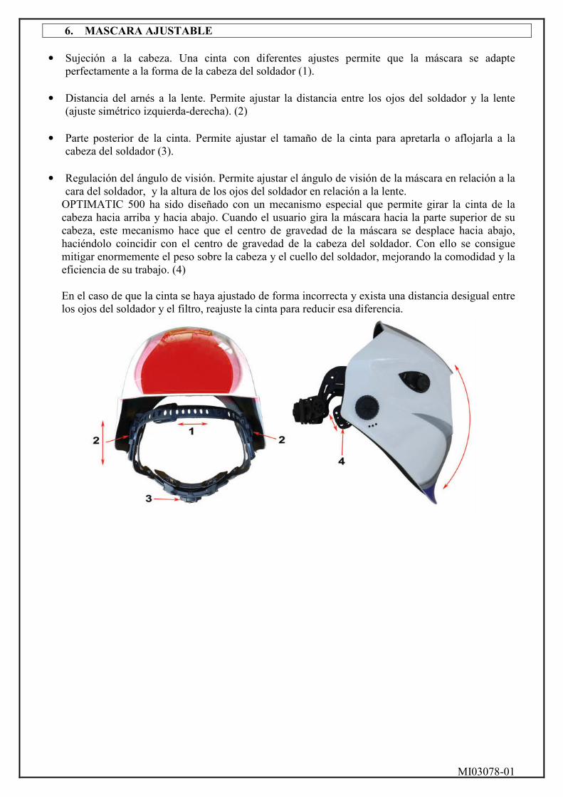
• Sujeción a la cabeza. Una cinta con diferentes ajustes permite que la máscara se adapte
perfectamente a la forma de la cabeza del soldador (1).
• Distancia del arnés a la lente. Permite ajustar la distancia entre los ojos del soldador y la lente (ajuste simétrico izquierda-derecha). (2)
• Parte posterior de la cinta. Permite ajustar el tamaño de la cinta para apretarla o aflojarla a la
cabeza del soldador (3). • Regulación del ángulo de visión. Permite ajustar el ángulo de visión de la máscara en relación a la
cara del soldador, y la altura de los ojos del soldador en relación a la lente. OPTIMATIC 500 ha sido diseñado con un mecanismo especial que permite girar la cinta de la cabeza hacia arriba y hacia abajo. Cuando el usuario gira la máscara hacia la parte superior de su cabeza, este mecanismo hace que el centro de gravedad de la máscara se desplace hacia abajo, haciéndolo coincidir con el centro de gravedad de la cabeza del soldador. Con ello se consigue mitigar enormemente el peso sobre la cabeza y el cuello del soldador, mejorando la comodidad y la eficiencia de su trabajo. (4)
En el caso de que la cinta se haya ajustado de forma incorrecta y exista una distancia desigual entre los ojos del soldador y el filtro, reajuste la cinta para reducir esa diferencia.
MI03078-01
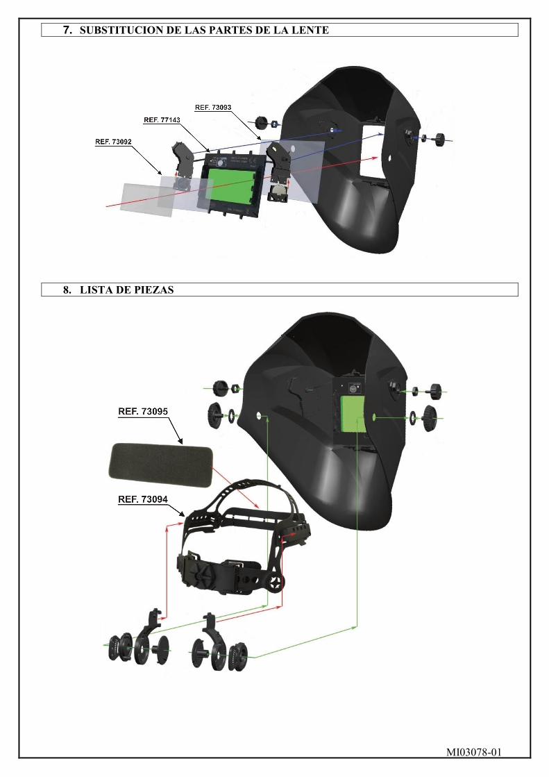
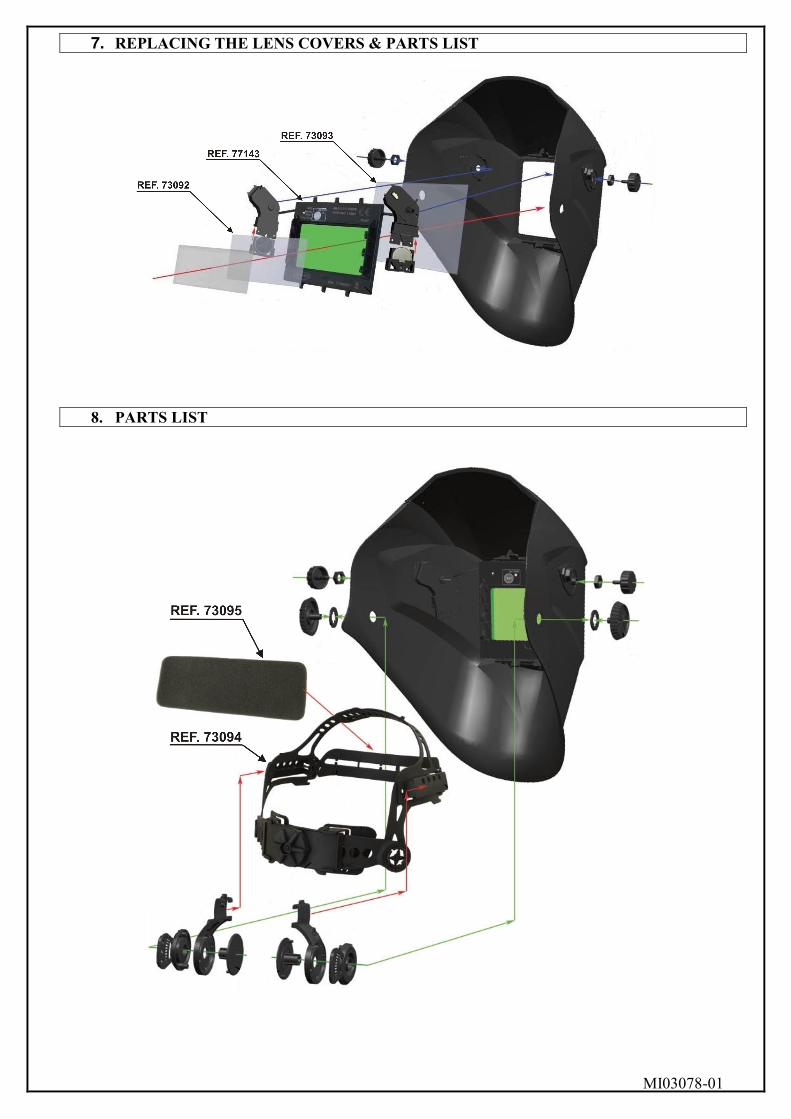
7. SUBSTITUCIO� DE LAS PARTES DE LA LE�TE
8. LISTA DE PIEZAS
MI03078-01
1. BEFORE WELDI�G
• Auto-Darkening filter Welding Helmet comes ready for use. The only thing you need to do before
you’re welding is to adjust the position of the headband and select the correct shade number for your application.
• Check the front cover lens to make sure that they are clean, and that no dirt is covering the four sensors on the front on the front of filter cartridge. Also check the front inside cover lens and front lens retaining frame sure that they are secure.
• Inspect all operating parts before use for signs of wear or damage. Any scratched, or pitted parts should be replaced immediately before using again to avoid severe personal injury.
• Check for light tightness before each use. • Select the shade number you require at the turn of a shade knob ( Seeing the shade guide table
No.1). Finally, be sure that the shade number is the correct setting for your application. • Adjust headband so that the helmet is seated as low as possible on the head and close to your face.
Adjust helmet’s angle when in the lowered position by turning the adjustable limitation washer.
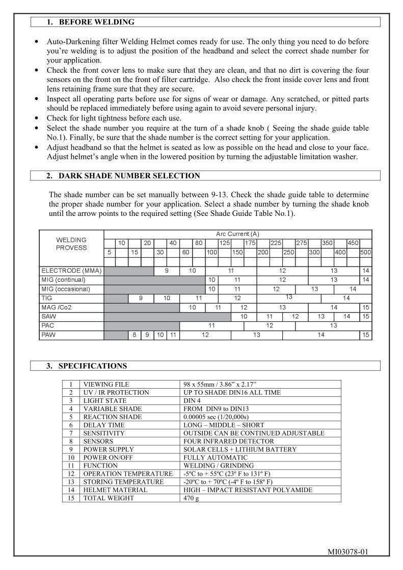
2. DARK SHADE �UMBER SELECTIO�
The shade number can be set manually between 9-13. Check the shade guide table to determine the proper shade number for your application. Select a shade number by turning the shade knob until the arrow points to the required setting (See Shade Guide Table No.1).
3. SPECIFICATIO�S
1 VIEWING FILE 98 x 55mm / 3.86” x 2.17” 2 UV / IR PROTECTION UP TO SHADE DIN16 ALL TIME 3 LIGHT STATE DIN 4 4 VARIABLE SHADE FROM DIN9 to DIN13 5 REACTION SHADE 0.00005 sec (1/20,000s) 6 DELAY TIME LONG – MIDDLE – SHORT 7 SENSITIVITY OUTSIDE CAN BE CONTINUED ADJUSTABLE 8 SENSORS FOUR INFRARED DETECTOR 9 POWER SUPPLY SOLAR CELLS + LITHIUM BATTERY 10 POWER ON/OFF FULLY AUTOMATIC 11 FUNCTION WELDING / GRINDING 12 OPERATION TEMPERATURE -5ºC to + 55ºC (23º F to 131º F) 13 STORING TEMPERATURE -20ºC to + 70ºC (-4º F to 158º F) 14 HELMET MATERIAL HIGH – IMPACT RESISTANT POLYAMIDE 15 TOTAL WEIGHT 470 g

MI03078-01
• The product is in full conformity with related DIN EN 379, DIN EN 175 safety standards and
ANSI / ISEA Z87.1-2010 safety standards. • Before welding, please keep clean on filter, front cover lens, inside cover lens and four optical
sensors. If front cover lens ans inside cover lens are burry and can not be clean, please replace them immediately.
4. VARIABLE SHADE CO�TROL / SE�SITIVITY CO�TROL / GRI�DI�G CO�TROL
• Welding / Grinding Handle: when grinding, the helmet shell can not bear the welding spatter
which is more than 73 grams and exceeding 120m/sec. The helmet meet standard DIN EN 175:1997 ( B impact Level). For other body parts helmet can not protect, please wear other safety products for protection.
• Sensitivity Knob: Before welding, please adjust the sensitivity to high position, If encountering the interference of Lighting lamp (the filter is darkening while not welding), please adjust the sensitivity towards low position slightly until the filter returns to slight state (please don’t make the helmet towards to light lamp source during this process, should towards to welding work piece). During welding, the sensitivity knob should be adjusted as high as possible, or it will be affect the darkening speed of filter.
ATTENTION: Operator must stop using the helmet immediately and contact with the dealer in time if the filter can not be darkening or the darkening speed is slow or the filter is flash. • Shade knob – before welding, please adjust the shade knob to proper shade no. based on welding
amperage to make primary welding for test (Seeing the shade Guide Table No.1). If the shade of filter is too darkening or too light, please adjust the shade knob slightly to correct position till the eyes can see the welding spot which is not glaring and can see welding molten spool. Please kindly note that it will damage the eyes if using welding helmet under incorrect shade no. (Too darkening or too light) for a long time.
ATTENTION: If the filter can not be darkening or the darkening share is not enough or the darkening speed is slow or the filter is flash, for such abnormal work, please find the reason immediately. If operator can not solve the problem, please must stop using the helmet immediately and contact with the dealer in time.
MI03078-01
5. DELAY TIME / TEST
• Delay time handle. There are three position ( Long, Middle, Short), it can adjust the switching
time of filter from dark state to light state, avoid the damage to eyes from the residual arc of welding pool due to too fast switching time to light state when welding is end (Break arc). The delay time is 0.3s - 0.5s (at short position); 0.4s – 0.6s (at middle of position); 0.6s – 0.9s (at long position). The switching time may vary due to different welding types and deferent sensitivity setting even delay time handle is at the same position.
If the filter is flash under low current welding, please adjust the delay time handle to long position, this can help to solve this problem.
• Test button. It can test the lithium battery is with power and if the filter is under normal work. If
the battery indicator is lightening (red) and the filter can be darkening when pressing down the test button, it means the filter is under normal work. If the battery indicator is not lightening or the light is very weak, please replace the lithium batteries, the type of battery is CR2450, QTY of battery is 2pcs. If the battery indicator is lightening but the filter is not darkening, it means there is some problem with the filter, please don’t use this filter anymore.
6. ADJUSTI�G HEADGEAR
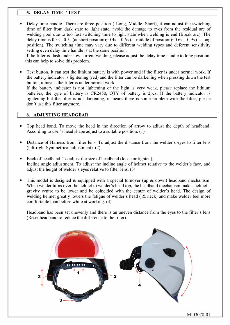
• Top head band. To move the head in the direction of arrow to adjust the depth of headband.
According to user’s head shape adjust to a suitable position. (1)
• Distance of Harness from filter lens. To adjust the distance from the welder’s eyes to filter lens (left-right Symmetrical adjustment). (2)
• Back of headband. To adjust the size of headband (loose or tighten).
Incline angle adjustment. To adjust the incline angle of helmet relative to the welder’s face, and adjust the height of welder’s eyes relative to filter lens. (3)
• This model is designed & equipped with a special turnover (up & down) headband mechanism.
When welder turns over the helmet to welder’s head top, the headband mechanism makes helmet’s gravity centre to be lower and be coincided with the centre of welder’s head. The design of welding helmet greatly lowers the fatigue of welder’s head ( & neck) and make welder feel more comfortable than before while at working. (4) Headband has been set unevenly and there is an uneven distance from the eyes to the filter’s lens (Reset headband to reduce the difference to the filter).
MI03078-01
7. REPLACI�G THE LE�S COVERS & PARTS LIST
8. PARTS LIST
MI03078-01
ATENCIÓN CLIENTE 902 43 12 19
Email: [email protected] Todos los clientes propietarios de equipos SOLTER gozaran de las ventajas del sistema
exclusivo de asistencia técnica de SOLTER.
En caso de avería o consulta técnica no dude en ponerse en contacto con nosotros y nuestro equipo de profesionales atenderá sus consultas de inmediato.
HOMOLOGACIONES
CERTIFICATE OF CO�FORMITY DECLARACION DE CONFORMIDAD DECLARACIÓ DE CONFORMITAT We SOLTER soldadura, s.l. NIF: B-17245127 Yo CTRA. NACIONAL 260, KM 122 L´empresa 17530 CAMPDEVANOL (GIRONA) SPAIN
Declare under our sole responsability that the product Declaro bajo mi responsabilidad que el producto Declara sota la seva responsabilitat que el producte
Name: Nombre: Nom: OPTIMATIC 500
Type: Tipo: Tipus: OPTIMATIC 500
Serial Number: Numero de serie: Nombre de sèrie: ALL THE UNITS MANUFACTURED SINCE
To which this declaration relates is in conformity with the following standard(s) or other normative document(s). Al que se refiere esta declaración está en conformidad con la(s) siguiente(s) norma(s) o documento(s) normativo(s). Al que es refereix aquesta declaració està de conformitat a la(es) següent(s) norma(es) o document(s) normatiu(s)
E� 175, E� 379:2003
Following the provisions of Directive(s) Siguiendo las prescripciones de la(s) Directiva(s) Seguint les prescripcions de la(s) Directiva(es)
2006/95/CE (LVD, EMC), 2002/95/EC (ROHS), 2002/96/EC (WEE), 89/686/CEE TECHNICAL DEPARTMENT Campdevànol a 22 de Junio de 2012
MI03078-01
CERTIFICADO DE GARANTÍA
( Válido sólo para España )
CERTIFICADO DE GARANTÍA
Distribuidor:
Fecha de venta:
MODELO Nº SERIE
Vendido a:
Dirección:
Población:
Exija su cumplimentación al adquirir el aparato:
SOLTER SOLDADURA S.L. garantiza a partir de la compra y durante 2 años, el artículo contra todo defecto de fabricación o de materiales. En caso de avería, la garantía cubre las piezas de recambio y la mano de obra, y el titular del equipo disfrutará en cada momento de todos los derechos que la normativa vigente conceda. La garantía no cubre averías debidas a un mal uso, mal trato o deterioro accidental, así como aquellos aparatos manipulados o reparados por una persona ajena a los Servicios Oficiales SOLTER:
ESPAÑOL: Para detalles de garantía fuera de España contacte con su distribuidor local.
ENGLISH: For details of guarantee outside Spain, contact your local supplies.
FRANÇAIS. Pour les détails de la garantie hors d’Espagne, contacter votre fournisseur.
DEUTSCH : Einzelheilen über die Garantie Auβerhalb des Spanien teilt ihnen gem ihr orticher Vertrieb mit.
PORTUGÊS : Para informaçoes sobre garantia, fora de Espahna, contacte o seu formecedor.
SOLTER SOLDADURA S.L. Ctra. N-260, Km. 122
17530 Campdevànol (Girona) Tel: (+34) 972 730 084 Fax: (+34) 972 712 157 Email: [email protected]
www.solter.com