ospf guias de configuracion
DESCRIPTION
OSPF Guias de ConfiguracionTRANSCRIPT

THE SPECIFICATIONS AND INFORMATION REGARDING THE PRODUCTS IN THIS MANUAL ARE SUBJECT TO CHANGE WITHOUT NOTICE. ALL STATEMENTS, INFORMATION, AND RECOMMENDATIONS IN THIS MANUAL ARE BELIEVED TO BE ACCURATE BUT ARE PRESENTED WITHOUT WARRANTY OF ANY KIND, EXPRESS OR IMPLIED. USERS MUST TAKE FULL RESPONSIBILITY FOR THEIR APPLICATION OF ANY PRODUCTS.
THE SOFTWARE LICENSE AND LIMITED WARRANTY FOR THE ACCOMPANYING PRODUCT ARE SET FORTH IN THE INFORMATION PACKET THAT SHIPPED WITH THE PRODUCT AND ARE INCORPORATED HEREIN BY THIS REFERENCE. IF YOU ARE UNABLE TO LOCATE THE SOFTWARE LICENSE OR LIMITED WARRANTY, CONTACT YOUR CISCO REPRESENTATIVE FOR A COPY.
The Cisco implementation of TCP header compression is an adaptation of a program developed by the University of California, Berkeley (UCB) as part of UCB’s public domain version of the UNIX operating system. All rights reserved. Copyright © 1981, Regents of the University of California.
NOTWITHSTANDING ANY OTHER WARRANTY HEREIN, ALL DOCUMENT FILES AND SOFTWARE OF THESE SUPPLIERS ARE PROVIDED “AS IS” WITH ALL FAULTS. CISCO AND THE ABOVE-NAMED SUPPLIERS DISCLAIM ALL WARRANTIES, EXPRESSED OR IMPLIED, INCLUDING, WITHOUT LIMITATION, THOSE OF MERCHANTABILITY, FITNESS FOR A PARTICULAR PURPOSE AND NONINFRINGEMENT OR ARISING FROM A COURSE OF DEALING, USAGE, OR TRADE PRACTICE.
IN NO EVENT SHALL CISCO OR ITS SUPPLIERS BE LIABLE FOR ANY INDIRECT, SPECIAL, CONSEQUENTIAL, OR INCIDENTAL DAMAGES, INCLUDING, WITHOUT LIMITATION, LOST PROFITS OR LOSS OR DAMAGE TO DATA ARISING OUT OF THE USE OR INABILITY TO USE THIS MANUAL, EVEN IF CISCO OR ITS SUPPLIERS HAVE BEEN ADVISED OF THE POSSIBILITY OF SUCH DAMAGES.
CCDE, CCENT, CCSI, Cisco Eos, Cisco HealthPresence, Cisco IronPort, the Cisco logo, Cisco Nurse Connect, Cisco Pulse, Cisco SensorBase, Cisco StackPower, Cisco StadiumVision, Cisco TelePresence, Cisco Unified Computing System, Cisco WebEx, DCE, Flip Channels, Flip for Good, Flip Mino, Flipshare (Design), Flip Ultra, Flip Video, Flip Video (Design), Instant Broadband, and Welcome to the Human Network are trademarks; Changing the Way We Work, Live, Play, and Learn, Cisco Capital, Cisco Capital (Design), Cisco:Financed (Stylized), Cisco Store, Flip Gift Card, and One Million Acts of Green are service marks; and Access Registrar, Aironet, AllTouch, AsyncOS, Bringing the Meeting To You, Catalyst, CCDA, CCDP, CCIE, CCIP, CCNA, CCNP, CCSP, CCVP, Cisco, the Cisco Certified Internetwork Expert logo, Cisco IOS, Cisco Lumin, Cisco Nexus, Cisco Press, Cisco Systems, Cisco Systems Capital, the Cisco Systems logo, Cisco Unity, Collaboration Without Limitation, Continuum, EtherFast, EtherSwitch, Event Center, Explorer, Follow Me Browsing, GainMaker, iLYNX, IOS, iPhone, IronPort, the IronPort logo, Laser Link, LightStream, Linksys, MeetingPlace, MeetingPlace Chime Sound, MGX, Networkers, Networking Academy, PCNow, PIX, PowerKEY, PowerPanels, PowerTV, PowerTV (Design), PowerVu, Prisma, ProConnect, ROSA, SenderBase, SMARTnet, Spectrum Expert, StackWise, WebEx, and the WebEx logo are registered trademarks of Cisco Systems, Inc. and/or its affiliates in the United States and certain other countries.
All other trademarks mentioned in this document or website are the property of their respective owners. The use of the word partner does not imply a partnership relationship between Cisco and any other company. (0910R)
Any Internet Protocol (IP) addresses used in this document are not intended to be actual addresses. Any examples, command display output, and figures included in the document are shown for illustrative purposes only. Any use of actual IP addresses in illustrative content is unintentional and coincidental.
Cisco IOS IP Routing: OSPF Configuration Guide© 2009 Cisco Systems, Inc. All rights reserved.
i
About Cisco IOS Software Documentation
Last Updated: October 14, 2009
This document describes the objectives, audience, conventions, and organization used in Cisco IOS software documentation. Also included are resources for obtaining technical assistance, additional documentation, and other information from Cisco. This document is organized into the following sections:
• Documentation Objectives, page i
• Audience, page i
• Documentation Conventions, page i
• Documentation Organization, page iii
• Additional Resources and Documentation Feedback, page xii
Documentation ObjectivesCisco IOS documentation describes the tasks and commands available to configure and maintain Cisco networking devices.
AudienceThe Cisco IOS documentation set is intended for users who configure and maintain Cisco networking devices (such as routers and switches) but who may not be familiar with the configuration and maintenance tasks, the relationship among tasks, or the Cisco IOS commands necessary to perform particular tasks. The Cisco IOS documentation set is also intended for those users experienced with Cisco IOS software who need to know about new features, new configuration options, and new software characteristics in the current Cisco IOS release.
Documentation ConventionsIn Cisco IOS documentation, the term router may be used to refer to various Cisco products; for example, routers, access servers, and switches. These and other networking devices that support Cisco IOS software are shown interchangeably in examples and are used only for illustrative purposes. An example that shows one product does not necessarily mean that other products are not supported.
About Cisco IOS Software DocumentationDocumentation Conventions
ii
This section contains the following topics:
• Typographic Conventions, page ii
• Command Syntax Conventions, page ii
• Software Conventions, page iii
• Reader Alert Conventions, page iii
Typographic ConventionsCisco IOS documentation uses the following typographic conventions:
Command Syntax ConventionsCisco IOS documentation uses the following command syntax conventions:
Convention Description
^ or Ctrl Both the ^ symbol and Ctrl represent the Control (Ctrl) key on a keyboard. For example, the key combination ^D or Ctrl-D means that you hold down the Control key while you press the D key. (Keys are indicated in capital letters but are not case sensitive.)
string A string is a nonquoted set of characters shown in italics. For example, when setting a Simple Network Management Protocol (SNMP) community string to public, do not use quotation marks around the string; otherwise, the string will include the quotation marks.
Convention Description
bold Bold text indicates commands and keywords that you enter as shown.
italic Italic text indicates arguments for which you supply values.
[x] Square brackets enclose an optional keyword or argument.
... An ellipsis (three consecutive nonbolded periods without spaces) after a syntax element indicates that the element can be repeated.
| A vertical line, called a pipe, that is enclosed within braces or square brackets indicates a choice within a set of keywords or arguments.
[x | y] Square brackets enclosing keywords or arguments separated by a pipe indicate an optional choice.
{x | y} Braces enclosing keywords or arguments separated by a pipe indicate a required choice.
[x {y | z}] Braces and a pipe within square brackets indicate a required choice within an optional element.

About Cisco IOS Software DocumentationDocumentation Organization
iii
Software ConventionsCisco IOS software uses the following program code conventions:
Reader Alert ConventionsCisco IOS documentation uses the following conventions for reader alerts:
Caution Means reader be careful. In this situation, you might do something that could result in equipment damage or loss of data.
Note Means reader take note. Notes contain helpful suggestions or references to material not covered in the manual.
Timesaver Means the described action saves time. You can save time by performing the action described in the paragraph.
Documentation OrganizationThis section describes the Cisco IOS documentation set, how it is organized, and how to access it on Cisco.com. It also lists the configuration guides, command references, and supplementary references and resources that comprise the documentation set. It contains the following topics:
• Cisco IOS Documentation Set, page iv
• Cisco IOS Documentation on Cisco.com, page iv
• Configuration Guides, Command References, and Supplementary Resources, page v
Convention Description
Courier font Courier font is used for information that is displayed on a PC or terminal screen.
Bold Courier font Bold Courier font indicates text that the user must enter.
< > Angle brackets enclose text that is not displayed, such as a password. Angle brackets also are used in contexts in which the italic font style is not supported; for example, ASCII text.
! An exclamation point at the beginning of a line indicates that the text that follows is a comment, not a line of code. An exclamation point is also displayed by Cisco IOS software for certain processes.
[ ] Square brackets enclose default responses to system prompts.
About Cisco IOS Software DocumentationDocumentation Organization
iv
Cisco IOS Documentation SetThe Cisco IOS documentation set consists of the following:
• Release notes and caveats provide information about platform, technology, and feature support for a release and describe severity 1 (catastrophic), severity 2 (severe), and select severity 3 (moderate) defects in released Cisco IOS software. Review release notes before other documents to learn whether updates have been made to a feature.
• Sets of configuration guides and command references organized by technology and published for each standard Cisco IOS release.
– Configuration guides—Compilations of documents that provide conceptual and task-oriented descriptions of Cisco IOS features.
– Command references—Compilations of command pages in alphabetical order that provide detailed information about the commands used in the Cisco IOS features and the processes that comprise the related configuration guides. For each technology, there is a single command reference that supports all Cisco IOS releases and that is updated at each standard release.
• Lists of all the commands in a specific release and all commands that are new, modified, removed, or replaced in the release.
• Command reference book for debug commands. Command pages are listed in alphabetical order.
• Reference book for system messages for all Cisco IOS releases.
Cisco IOS Documentation on Cisco.comThe following sections describe the organization of the Cisco IOS documentation set and how to access various document types.
Use Cisco Feature Navigator to find information about platform support and Cisco IOS and Catalyst OS software image support. To access Cisco Feature Navigator, go to http://www.cisco.com/go/cfn. An account on Cisco.com is not required.
New Features List
The New Features List for each release provides a list of all features in the release with hyperlinks to the feature guides in which they are documented.
Feature Guides
Cisco IOS features are documented in feature guides. Feature guides describe one feature or a group of related features that are supported on many different software releases and platforms. Your Cisco IOS software release or platform may not support all the features documented in a feature guide. See the Feature Information table at the end of the feature guide for information about which features in that guide are supported in your software release.
Configuration Guides
Configuration guides are provided by technology and release and comprise a set of individual feature guides relevant to the release and technology.
About Cisco IOS Software DocumentationDocumentation Organization
v
Command References
Command reference books contain descriptions of Cisco IOS commands that are supported in many different software releases and on many different platforms. The books are organized by technology. For information about all Cisco IOS commands, use the Command Lookup Tool at http://tools.cisco.com/Support/CLILookup or the Cisco IOS Master Command List, All Releases, at http://www.cisco.com/en/US/docs/ios/mcl/allreleasemcl/all_book.html.
Cisco IOS Supplementary Documents and Resources
Supplementary documents and resources are listed in Table 2 on page xi.
Configuration Guides, Command References, and Supplementary ResourcesTable 1 lists, in alphabetical order, Cisco IOS software configuration guides and command references, including brief descriptions of the contents of the documents. The Cisco IOS command references contain commands for Cisco IOS software for all releases. The configuration guides and command references support many different software releases and platforms. Your Cisco IOS software release or platform may not support all these technologies.
Table 2 lists documents and resources that supplement the Cisco IOS software configuration guides and command references. These supplementary resources include release notes and caveats; master command lists; new, modified, removed, and replaced command lists; system messages; and the debug command reference.
For additional information about configuring and operating specific networking devices, and to access Cisco IOS documentation, go to the Product/Technologies Support area of Cisco.com at the following location:
http://www.cisco.com/go/techdocs
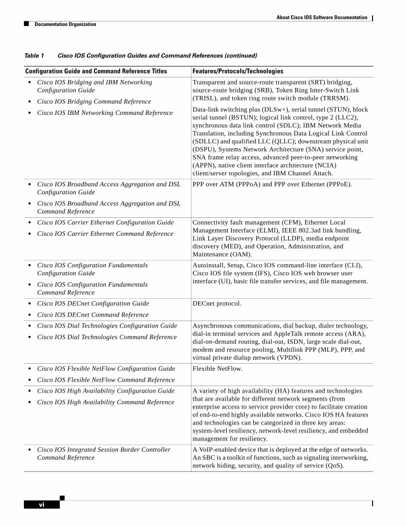
Table 1 Cisco IOS Configuration Guides and Command References
Configuration Guide and Command Reference Titles Features/Protocols/Technologies
• Cisco IOS AppleTalk Configuration Guide
• Cisco IOS AppleTalk Command Reference
AppleTalk protocol.
• Cisco IOS Asynchronous Transfer Mode Configuration Guide
• Cisco IOS Asynchronous Transfer Mode Command Reference
LAN ATM, multiprotocol over ATM (MPoA), and WAN ATM.
About Cisco IOS Software DocumentationDocumentation Organization
vi
• Cisco IOS Bridging and IBM Networking Configuration Guide
• Cisco IOS Bridging Command Reference
• Cisco IOS IBM Networking Command Reference
Transparent and source-route transparent (SRT) bridging, source-route bridging (SRB), Token Ring Inter-Switch Link (TRISL), and token ring route switch module (TRRSM).
Data-link switching plus (DLSw+), serial tunnel (STUN), block serial tunnel (BSTUN); logical link control, type 2 (LLC2), synchronous data link control (SDLC); IBM Network Media Translation, including Synchronous Data Logical Link Control (SDLLC) and qualified LLC (QLLC); downstream physical unit (DSPU), Systems Network Architecture (SNA) service point, SNA frame relay access, advanced peer-to-peer networking (APPN), native client interface architecture (NCIA) client/server topologies, and IBM Channel Attach.
• Cisco IOS Broadband Access Aggregation and DSL Configuration Guide
• Cisco IOS Broadband Access Aggregation and DSL Command Reference
PPP over ATM (PPPoA) and PPP over Ethernet (PPPoE).
• Cisco IOS Carrier Ethernet Configuration Guide
• Cisco IOS Carrier Ethernet Command Reference
Connectivity fault management (CFM), Ethernet Local Management Interface (ELMI), IEEE 802.3ad link bundling, Link Layer Discovery Protocol (LLDP), media endpoint discovery (MED), and Operation, Administration, and Maintenance (OAM).
• Cisco IOS Configuration Fundamentals Configuration Guide
• Cisco IOS Configuration Fundamentals Command Reference
Autoinstall, Setup, Cisco IOS command-line interface (CLI), Cisco IOS file system (IFS), Cisco IOS web browser user interface (UI), basic file transfer services, and file management.
• Cisco IOS DECnet Configuration Guide
• Cisco IOS DECnet Command Reference
DECnet protocol.
• Cisco IOS Dial Technologies Configuration Guide
• Cisco IOS Dial Technologies Command Reference
Asynchronous communications, dial backup, dialer technology, dial-in terminal services and AppleTalk remote access (ARA), dial-on-demand routing, dial-out, ISDN, large scale dial-out, modem and resource pooling, Multilink PPP (MLP), PPP, and virtual private dialup network (VPDN).
• Cisco IOS Flexible NetFlow Configuration Guide
• Cisco IOS Flexible NetFlow Command Reference
Flexible NetFlow.
• Cisco IOS High Availability Configuration Guide
• Cisco IOS High Availability Command Reference
A variety of high availability (HA) features and technologies that are available for different network segments (from enterprise access to service provider core) to facilitate creation of end-to-end highly available networks. Cisco IOS HA features and technologies can be categorized in three key areas: system-level resiliency, network-level resiliency, and embedded management for resiliency.
• Cisco IOS Integrated Session Border Controller Command Reference
A VoIP-enabled device that is deployed at the edge of networks. An SBC is a toolkit of functions, such as signaling interworking, network hiding, security, and quality of service (QoS).
Table 1 Cisco IOS Configuration Guides and Command References (continued)
Configuration Guide and Command Reference Titles Features/Protocols/Technologies

About Cisco IOS Software DocumentationDocumentation Organization
vii
• Cisco IOS Intelligent Services Gateway Configuration Guide
• Cisco IOS Intelligent Services Gateway Command Reference
Subscriber identification, service and policy determination, session creation, session policy enforcement, session life-cycle management, accounting for access and service usage, and session state monitoring.
• Cisco IOS Interface and Hardware Component Configuration Guide
• Cisco IOS Interface and Hardware Component Command Reference
LAN interfaces, logical interfaces, serial interfaces, virtual interfaces, and interface configuration.
• Cisco IOS IP Addressing Services Configuration Guide
• Cisco IOS IP Addressing Services Command Reference
Address Resolution Protocol (ARP), Network Address Translation (NAT), Domain Name System (DNS), Dynamic Host Configuration Protocol (DHCP), and Next Hop Address Resolution Protocol (NHRP).
• Cisco IOS IP Application Services Configuration Guide
• Cisco IOS IP Application Services Command Reference
Enhanced Object Tracking (EOT), Gateway Load Balancing Protocol (GLBP), Hot Standby Router Protocol (HSRP), IP Services, Server Load Balancing (SLB), Stream Control Transmission Protocol (SCTP), TCP, Web Cache Communication Protocol (WCCP), User Datagram Protocol (UDP), and Virtual Router Redundancy Protocol (VRRP).
• Cisco IOS IP Mobility Configuration Guide
• Cisco IOS IP Mobility Command Reference
Mobile ad hoc networks (MANet) and Cisco mobile networks.
• Cisco IOS IP Multicast Configuration Guide
• Cisco IOS IP Multicast Command Reference
Protocol Independent Multicast (PIM) sparse mode (PIM-SM), bidirectional PIM (bidir-PIM), Source Specific Multicast (SSM), Multicast Source Discovery Protocol (MSDP), Internet Group Management Protocol (IGMP), and Multicast VPN (MVPN).
• Cisco IOS IP Routing Protocols Configuration Guide
• Cisco IOS IP Routing Protocols Command Reference
Border Gateway Protocol (BGP), multiprotocol BGP, multiprotocol BGP extensions for IP multicast, bidirectional forwarding detection (BFD), Enhanced Interior Gateway Routing Protocol (EIGRP), Interior Gateway Routing Protocol (IGRP), Intermediate System-to-Intermediate System (IS-IS), On-Demand Routing (ODR), Open Shortest Path First (OSPF), and Routing Information Protocol (RIP).
• Cisco IOS IP Routing: BFD Configuration Guide Bidirectional forwarding detection (BFD).
• Cisco IOS IP Routing: BGP Configuration Guide
• Cisco IOS IP Routing: BGP Command Reference
Border Gateway Protocol (BGP), multiprotocol BGP, multiprotocol BGP extensions for IP multicast.
• Cisco IOS IP Routing: EIGRP Configuration Guide
• Cisco IOS IP Routing: EIGRP Command Reference
Enhanced Interior Gateway Routing Protocol (EIGRP).
• Cisco IOS IP Routing: ISIS Configuration Guide
• Cisco IOS IP Routing: ISIS Command Reference
Intermediate System-to-Intermediate System (IS-IS).
• Cisco IOS IP Routing: ODR Configuration Guide
• Cisco IOS IP Routing: ODR Command Reference
On-Demand Routing (ODR).
Table 1 Cisco IOS Configuration Guides and Command References (continued)
Configuration Guide and Command Reference Titles Features/Protocols/Technologies

About Cisco IOS Software DocumentationDocumentation Organization
viii
• Cisco IOS IP Routing: OSPF Configuration Guide
• Cisco IOS IP Routing: OSPF Command Reference
Open Shortest Path First (OSPF).
• Cisco IOS IP Routing: Protocol-Independent Configuration Guide
• Cisco IOS IP Routing: Protocol-Independent Command Reference
IP routing protocol-independent features and commands. Generic policy-based routing (PBR) features and commands are included.
• Cisco IOS IP Routing: RIP Configuration Guide
• Cisco IOS IP Routing: RIP Command Reference
Routing Information Protocol (RIP).
• Cisco IOS IP SLAs Configuration Guide
• Cisco IOS IP SLAs Command Reference
Cisco IOS IP Service Level Agreements (IP SLAs).
• Cisco IOS IP Switching Configuration Guide
• Cisco IOS IP Switching Command Reference
Cisco Express Forwarding, fast switching, and Multicast Distributed Switching (MDS).
• Cisco IOS IPv6 Configuration Guide
• Cisco IOS IPv6 Command Reference
For IPv6 features, protocols, and technologies, go to the IPv6 “Start Here” document.
• Cisco IOS ISO CLNS Configuration Guide
• Cisco IOS ISO CLNS Command Reference
ISO Connectionless Network Service (CLNS).
• Cisco IOS LAN Switching Configuration Guide
• Cisco IOS LAN Switching Command Reference
VLANs, Inter-Switch Link (ISL) encapsulation, IEEE 802.10 encapsulation, IEEE 802.1Q encapsulation, and multilayer switching (MLS).
• Cisco IOS Mobile Wireless Gateway GPRS Support Node Configuration Guide
• Cisco IOS Mobile Wireless Gateway GPRS Support Node Command Reference
Cisco IOS Gateway GPRS Support Node (GGSN) in a 2.5-generation general packet radio service (GPRS) and 3-generation universal mobile telecommunication system (UMTS) network.
• Cisco IOS Mobile Wireless Home Agent Configuration Guide
• Cisco IOS Mobile Wireless Home Agent Command Reference
Cisco Mobile Wireless Home Agent, an anchor point for mobile terminals for which mobile IP or proxy mobile IP services are provided.
• Cisco IOS Mobile Wireless Packet Data Serving Node Configuration Guide
• Cisco IOS Mobile Wireless Packet Data Serving Node Command Reference
Cisco Packet Data Serving Node (PDSN), a wireless gateway that is between the mobile infrastructure and standard IP networks and that enables packet data services in a code division multiple access (CDMA) environment.
• Cisco IOS Mobile Wireless Radio Access Networking Configuration Guide
• Cisco IOS Mobile Wireless Radio Access Networking Command Reference
Cisco IOS radio access network products.
• Cisco IOS Multiprotocol Label Switching Configuration Guide
• Cisco IOS Multiprotocol Label Switching Command Reference
MPLS Label Distribution Protocol (LDP), MPLS Layer 2 VPNs, MPLS Layer 3 VPNs, MPLS traffic engineering (TE), and MPLS Embedded Management (EM) and MIBs.
Table 1 Cisco IOS Configuration Guides and Command References (continued)
Configuration Guide and Command Reference Titles Features/Protocols/Technologies
About Cisco IOS Software DocumentationDocumentation Organization
ix
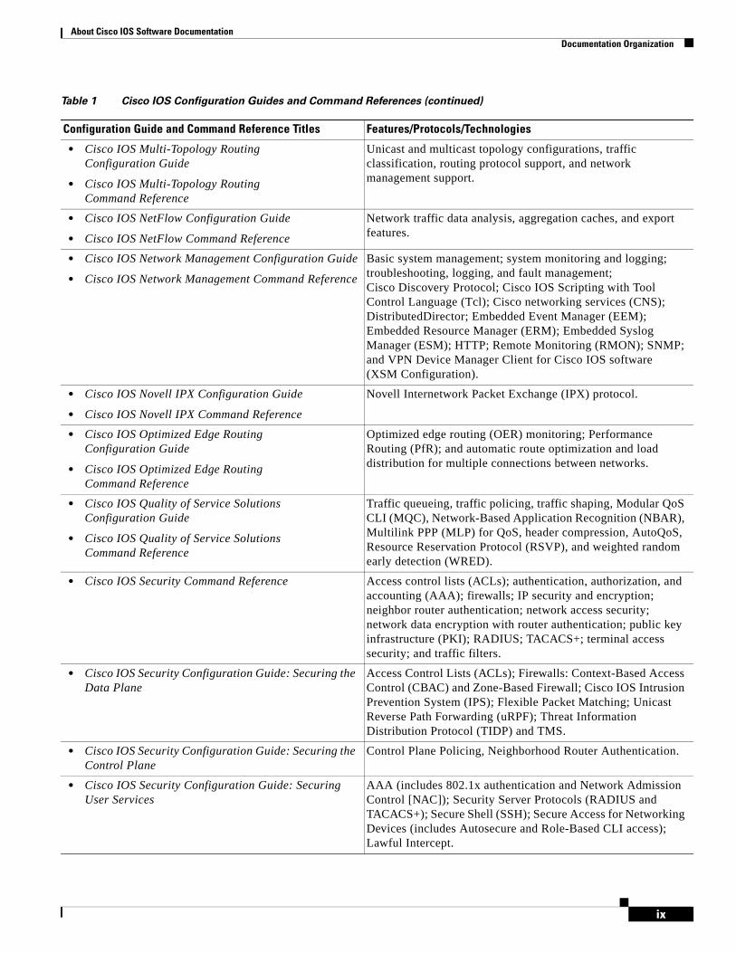
• Cisco IOS Multi-Topology Routing Configuration Guide
• Cisco IOS Multi-Topology Routing Command Reference
Unicast and multicast topology configurations, traffic classification, routing protocol support, and network management support.
• Cisco IOS NetFlow Configuration Guide
• Cisco IOS NetFlow Command Reference
Network traffic data analysis, aggregation caches, and export features.
• Cisco IOS Network Management Configuration Guide
• Cisco IOS Network Management Command Reference
Basic system management; system monitoring and logging; troubleshooting, logging, and fault management; Cisco Discovery Protocol; Cisco IOS Scripting with Tool Control Language (Tcl); Cisco networking services (CNS); DistributedDirector; Embedded Event Manager (EEM); Embedded Resource Manager (ERM); Embedded Syslog Manager (ESM); HTTP; Remote Monitoring (RMON); SNMP; and VPN Device Manager Client for Cisco IOS software (XSM Configuration).
• Cisco IOS Novell IPX Configuration Guide
• Cisco IOS Novell IPX Command Reference
Novell Internetwork Packet Exchange (IPX) protocol.
• Cisco IOS Optimized Edge Routing Configuration Guide
• Cisco IOS Optimized Edge Routing Command Reference
Optimized edge routing (OER) monitoring; Performance Routing (PfR); and automatic route optimization and load distribution for multiple connections between networks.
• Cisco IOS Quality of Service Solutions Configuration Guide
• Cisco IOS Quality of Service Solutions Command Reference
Traffic queueing, traffic policing, traffic shaping, Modular QoS CLI (MQC), Network-Based Application Recognition (NBAR), Multilink PPP (MLP) for QoS, header compression, AutoQoS, Resource Reservation Protocol (RSVP), and weighted random early detection (WRED).
• Cisco IOS Security Command Reference Access control lists (ACLs); authentication, authorization, and accounting (AAA); firewalls; IP security and encryption; neighbor router authentication; network access security; network data encryption with router authentication; public key infrastructure (PKI); RADIUS; TACACS+; terminal access security; and traffic filters.
• Cisco IOS Security Configuration Guide: Securing the Data Plane
Access Control Lists (ACLs); Firewalls: Context-Based Access Control (CBAC) and Zone-Based Firewall; Cisco IOS Intrusion Prevention System (IPS); Flexible Packet Matching; Unicast Reverse Path Forwarding (uRPF); Threat Information Distribution Protocol (TIDP) and TMS.
• Cisco IOS Security Configuration Guide: Securing the Control Plane
Control Plane Policing, Neighborhood Router Authentication.
• Cisco IOS Security Configuration Guide: Securing User Services
AAA (includes 802.1x authentication and Network Admission Control [NAC]); Security Server Protocols (RADIUS and TACACS+); Secure Shell (SSH); Secure Access for Networking Devices (includes Autosecure and Role-Based CLI access); Lawful Intercept.
Table 1 Cisco IOS Configuration Guides and Command References (continued)
Configuration Guide and Command Reference Titles Features/Protocols/Technologies
About Cisco IOS Software DocumentationDocumentation Organization
x
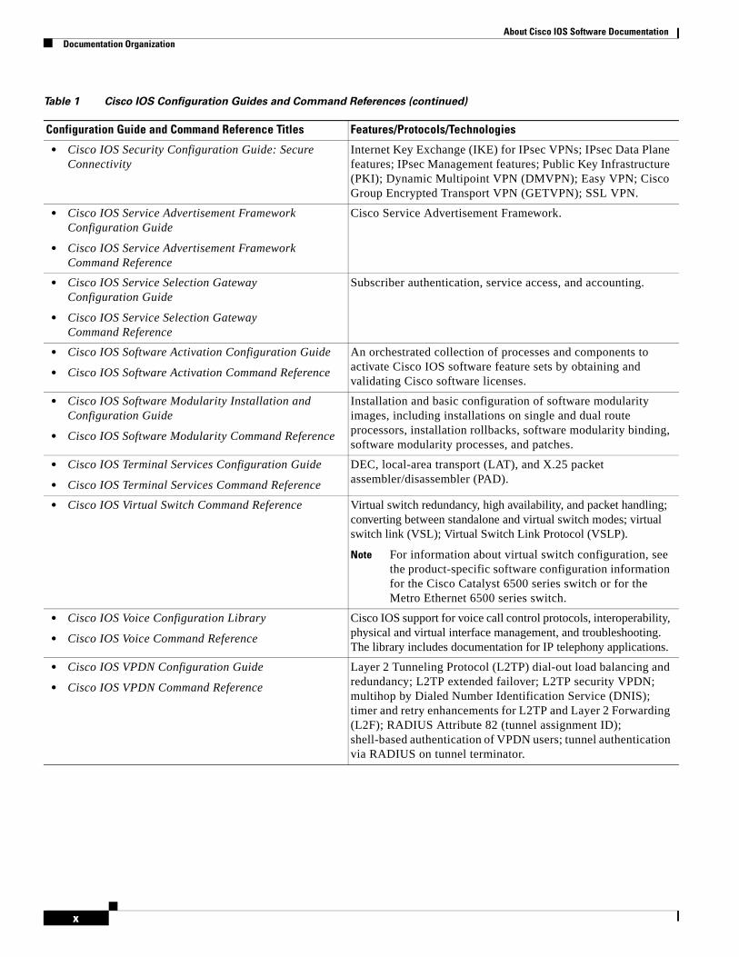
• Cisco IOS Security Configuration Guide: Secure Connectivity
Internet Key Exchange (IKE) for IPsec VPNs; IPsec Data Plane features; IPsec Management features; Public Key Infrastructure (PKI); Dynamic Multipoint VPN (DMVPN); Easy VPN; Cisco Group Encrypted Transport VPN (GETVPN); SSL VPN.
• Cisco IOS Service Advertisement Framework Configuration Guide
• Cisco IOS Service Advertisement Framework Command Reference
Cisco Service Advertisement Framework.
• Cisco IOS Service Selection Gateway Configuration Guide
• Cisco IOS Service Selection Gateway Command Reference
Subscriber authentication, service access, and accounting.
• Cisco IOS Software Activation Configuration Guide
• Cisco IOS Software Activation Command Reference
An orchestrated collection of processes and components to activate Cisco IOS software feature sets by obtaining and validating Cisco software licenses.
• Cisco IOS Software Modularity Installation and Configuration Guide
• Cisco IOS Software Modularity Command Reference
Installation and basic configuration of software modularity images, including installations on single and dual route processors, installation rollbacks, software modularity binding, software modularity processes, and patches.
• Cisco IOS Terminal Services Configuration Guide
• Cisco IOS Terminal Services Command Reference
DEC, local-area transport (LAT), and X.25 packet assembler/disassembler (PAD).
• Cisco IOS Virtual Switch Command Reference Virtual switch redundancy, high availability, and packet handling; converting between standalone and virtual switch modes; virtual switch link (VSL); Virtual Switch Link Protocol (VSLP).
Note For information about virtual switch configuration, see the product-specific software configuration information for the Cisco Catalyst 6500 series switch or for the Metro Ethernet 6500 series switch.
• Cisco IOS Voice Configuration Library
• Cisco IOS Voice Command Reference
Cisco IOS support for voice call control protocols, interoperability, physical and virtual interface management, and troubleshooting. The library includes documentation for IP telephony applications.
• Cisco IOS VPDN Configuration Guide
• Cisco IOS VPDN Command Reference
Layer 2 Tunneling Protocol (L2TP) dial-out load balancing and redundancy; L2TP extended failover; L2TP security VPDN; multihop by Dialed Number Identification Service (DNIS); timer and retry enhancements for L2TP and Layer 2 Forwarding (L2F); RADIUS Attribute 82 (tunnel assignment ID); shell-based authentication of VPDN users; tunnel authentication via RADIUS on tunnel terminator.
Table 1 Cisco IOS Configuration Guides and Command References (continued)
Configuration Guide and Command Reference Titles Features/Protocols/Technologies
About Cisco IOS Software DocumentationDocumentation Organization
xi
Table 2 lists documents and resources that supplement the Cisco IOS software configuration guides and command references.
• Cisco IOS Wide-Area Networking Configuration Guide
• Cisco IOS Wide-Area Networking Command Reference
Frame Relay; Layer 2 Tunnel Protocol Version 3 (L2TPv3); L2VPN Pseudowire Redundancy; L2VPN Interworking; Layer 2 Local Switching; Link Access Procedure, Balanced (LAPB); and X.25.
• Cisco IOS Wireless LAN Configuration Guide
• Cisco IOS Wireless LAN Command Reference
Broadcast key rotation, IEEE 802.11x support, IEEE 802.1x authenticator, IEEE 802.1x local authentication service for Extensible Authentication Protocol-Flexible Authentication via Secure Tunneling (EAP-FAST), Multiple Basic Service Set ID (BSSID), Wi-Fi Multimedia (WMM) required elements, and Wi-Fi Protected Access (WPA).
Table 1 Cisco IOS Configuration Guides and Command References (continued)
Configuration Guide and Command Reference Titles Features/Protocols/Technologies
Table 2 Cisco IOS Supplementary Documents and Resources
Document Title or Resource Description
Cisco IOS Master Command List, All Releases Alphabetical list of all the commands documented in all Cisco IOS releases.
Cisco IOS New, Modified, Removed, and Replaced Commands
List of all the new, modified, removed, and replaced commands for a Cisco IOS release.
Cisco IOS Software System Messages List of Cisco IOS system messages and descriptions. System messages may indicate problems with your system, may be informational only, or may help diagnose problems with communications lines, internal hardware, or system software.
Cisco IOS Debug Command Reference Alphabetical list of debug commands including brief descriptions of use, command syntax, and usage guidelines.
Release Notes and Caveats Information about new and changed features, system requirements, and other useful information about specific software releases; information about defects in specific Cisco IOS software releases.
MIBs Files used for network monitoring. To locate and download MIBs for selected platforms, Cisco IOS releases, and feature sets, use Cisco MIB Locator.
RFCs Standards documents maintained by the Internet Engineering Task Force (IETF) that Cisco IOS documentation references where applicable. The full text of referenced RFCs may be obtained at the following URL:
http://www.rfc-editor.org/

About Cisco IOS Software DocumentationAdditional Resources and Documentation Feedback
xii
Additional Resources and Documentation FeedbackWhat’s New in Cisco Product Documentation is released monthly and describes all new and revised Cisco technical documentation. The What’s New in Cisco Product Documentation publication also provides information about obtaining the following resources:
• Technical documentation
• Cisco product security overview
• Product alerts and field notices
• Technical assistance
Cisco IOS technical documentation includes embedded feedback forms where you can rate documents and provide suggestions for improvement. Your feedback helps us improve our documentation.
CCDE, CCENT, CCSI, Cisco Eos, Cisco HealthPresence, Cisco IronPort, the Cisco logo, Cisco Lumin, Cisco Nexus, Cisco Nurse Connect, Cisco Pulse, Cisco StackPower, Cisco StadiumVision, Cisco TelePresence, Cisco Unified Computing System, Cisco WebEx, DCE, Flip Channels, Flip for Good, Flip Mino, Flipshare (Design), Flip Ultra, Flip Video, Flip Video (Design), Instant Broadband, and Welcome to the Human Network are trademarks; Changing the Way We Work, Live, Play, and Learn, Cisco Capital, Cisco Capital (Design), Cisco:Financed (Stylized), Cisco Store, and Flip Gift Card are service marks; and Access Registrar, Aironet, AllTouch, AsyncOS, Bringing the Meeting To You, Catalyst, CCDA, CCDP, CCIE, CCIP, CCNA, CCNP, CCSP, CCVP, Cisco, the Cisco Certified Internetwork Expert logo, Cisco IOS, Cisco Press, Cisco Systems, Cisco Systems Capital, the Cisco Systems logo, Cisco Unity, Collaboration Without Limitation, Continuum, EtherFast, EtherSwitch, Event Center, Explorer, Fast Step, Follow Me Browsing, FormShare, GainMaker, GigaDrive, HomeLink, iLYNX, Internet Quotient, IOS, iPhone, iQuick Study, IronPort, the IronPort logo, Laser Link, LightStream, Linksys, MediaTone, MeetingPlace, MeetingPlace Chime Sound, MGX, Networkers, Networking Academy, Network Registrar, PCNow, PIX, PowerKEY, PowerPanels, PowerTV, PowerTV (Design), PowerVu, Prisma, ProConnect, ROSA, ScriptShare, SenderBase, SMARTnet, Spectrum Expert, StackWise, The Fastest Way to Increase Your Internet Quotient, TransPath, WebEx, and the WebEx logo are registered trademarks of Cisco Systems, Inc. and/or its affiliates in the United States and certain other countries.
All other trademarks mentioned in this document or website are the property of their respective owners. The use of the word partner does not imply a partnership relationship between Cisco and any other company. (0908R)
Any Internet Protocol (IP) addresses and phone numbers used in this document are not intended to be actual addresses and phone numbers. Any examples, command display output, network topology diagrams, and other figures included in the document are shown for illustrative purposes only. Any use of actual IP addresses or phone numbers in illustrative content is unintentional and coincidental.
© 2008–2009 Cisco Systems, Inc. All rights reserved.
i
Using the Command-Line Interface in Cisco IOS Software
Last Updated: October 14, 2009
This document provides basic information about the command-line interface (CLI) in Cisco IOS software and how you can use some of the CLI features. This document contains the following sections:
• Initially Configuring a Device, page i
• Using the CLI, page ii
• Saving Changes to a Configuration, page xi
• Additional Information, page xii
For more information about using the CLI, see the “Using the Cisco IOS Command-Line Interface” section of the Cisco IOS Configuration Fundamentals Configuration Guide.
For information about the software documentation set, see the “About Cisco IOS Software Documentation” document.
Initially Configuring a DeviceInitially configuring a device varies by platform. For information about performing an initial configuration, see the hardware installation documentation that is provided with the original packaging of the product or go to the Product/Technologies Support area of Cisco.com at http://www.cisco.com/go/techdocs.
After you have performed the initial configuration and connected the device to your network, you can configure the device by using the console port or a remote access method, such as Telnet or Secure Shell (SSH), to access the CLI or by using the configuration method provided on the device, such as Security Device Manager.
Using the Command-Line Interface in Cisco IOS SoftwareUsing the CLI
ii
Changing the Default Settings for a Console or AUX Port
There are only two changes that you can make to a console port and an AUX port:
• Change the port speed with the config-register 0x command. Changing the port speed is not recommended. The well-known default speed is 9600.
• Change the behavior of the port; for example, by adding a password or changing the timeout value.
Note The AUX port on the Route Processor (RP) installed in a Cisco ASR 1000 series router does not serve any useful customer purpose and should be accessed only under the advisement of a customer support representative.
Using the CLIThis section describes the following topics:
• Understanding Command Modes, page ii
• Using the Interactive Help Feature, page v
• Understanding Command Syntax, page vi
• Understanding Enable and Enable Secret Passwords, page vii
• Using the Command History Feature, page viii
• Abbreviating Commands, page ix
• Using Aliases for CLI Commands, page ix
• Using the no and default Forms of Commands, page x
• Using the debug Command, page x
• Filtering Output Using Output Modifiers, page x
• Understanding CLI Error Messages, page xi
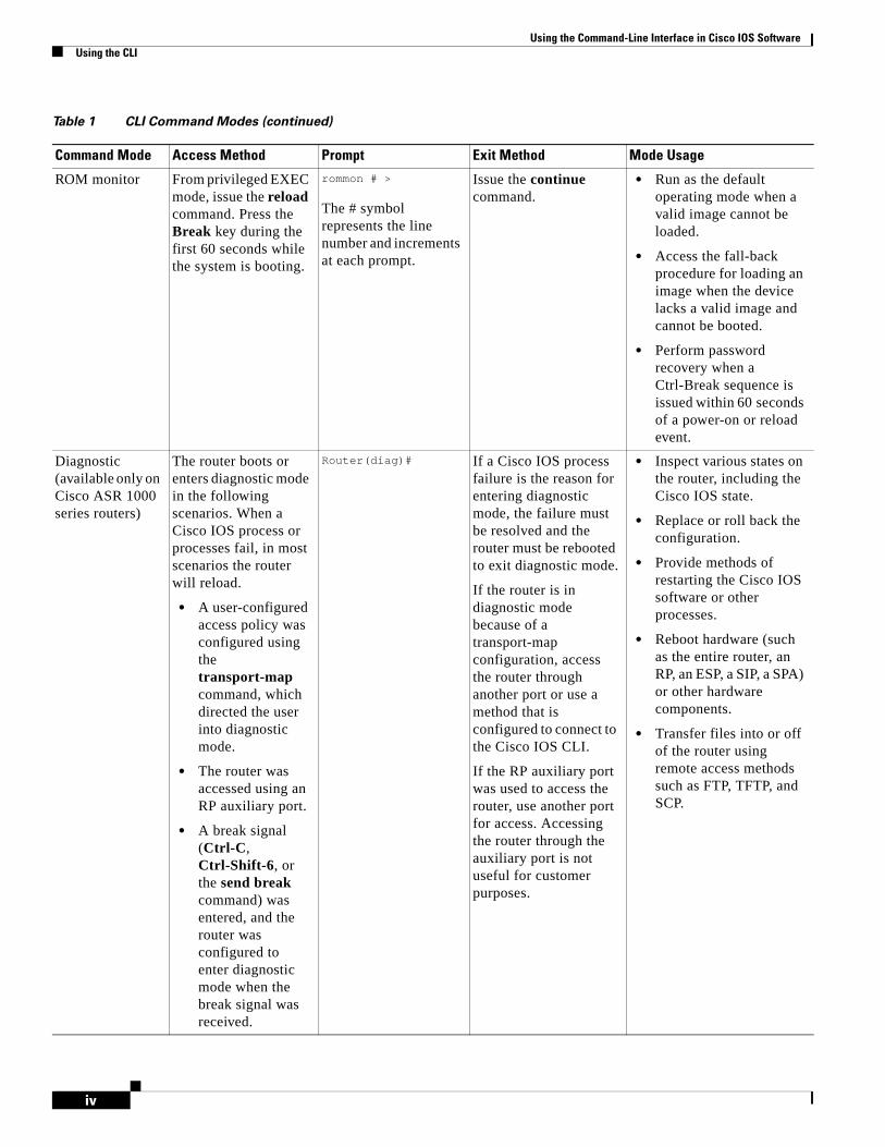
Understanding Command ModesThe CLI command mode structure is hierarchical, and each mode supports a set of specific commands. This section describes the most common of the many modes that exist.
Table 1 lists common command modes with associated CLI prompts, access and exit methods, and a brief description of how each mode is used.

Using the Command-Line Interface in Cisco IOS SoftwareUsing the CLI
iii
Table 1 CLI Command Modes
Command Mode Access Method Prompt Exit Method Mode Usage
User EXEC Log in. Router> Issue the logout or exit command.
• Change terminal settings.
• Perform basic tests.
• Display device status.
Privileged EXEC From user EXEC mode, issue the enable command.
Router# Issue the disable command or the exit command to return to user EXEC mode.
• Issue show and debug commands.
• Copy images to the device.
• Reload the device.
• Manage device configuration files.
• Manage device file systems.
Global configuration
From privileged EXEC mode, issue the configure terminal command.
Router(config)# Issue the exit command or the end command to return to privileged EXEC mode.
Configure the device.
Interface configuration
From global configuration mode, issue the interface command.
Router(config-if)# Issue the exit command to return to global configuration mode or the end command to return to privileged EXEC mode.
Configure individual interfaces.
Line configuration
From global configuration mode, issue the line vty or line console command.
Router(config-line)# Issue the exit command to return to global configuration mode or the end command to return to privileged EXEC mode.
Configure individual terminal lines.
Using the Command-Line Interface in Cisco IOS SoftwareUsing the CLI
iv
ROM monitor From privileged EXEC mode, issue the reload command. Press the Break key during the first 60 seconds while the system is booting.
rommon # >
The # symbol represents the line number and increments at each prompt.
Issue the continue command.
• Run as the default operating mode when a valid image cannot be loaded.
• Access the fall-back procedure for loading an image when the device lacks a valid image and cannot be booted.
• Perform password recovery when a Ctrl-Break sequence is issued within 60 seconds of a power-on or reload event.
Diagnostic (available only on Cisco ASR 1000 series routers)
The router boots or enters diagnostic mode in the following scenarios. When a Cisco IOS process or processes fail, in most scenarios the router will reload.
• A user-configured access policy was configured using the transport-map command, which directed the user into diagnostic mode.
• The router was accessed using an RP auxiliary port.
• A break signal (Ctrl-C, Ctrl-Shift-6, or the send break command) was entered, and the router was configured to enter diagnostic mode when the break signal was received.
Router(diag)# If a Cisco IOS process failure is the reason for entering diagnostic mode, the failure must be resolved and the router must be rebooted to exit diagnostic mode.
If the router is in diagnostic mode because of a transport-map configuration, access the router through another port or use a method that is configured to connect to the Cisco IOS CLI.
If the RP auxiliary port was used to access the router, use another port for access. Accessing the router through the auxiliary port is not useful for customer purposes.
• Inspect various states on the router, including the Cisco IOS state.
• Replace or roll back the configuration.
• Provide methods of restarting the Cisco IOS software or other processes.
• Reboot hardware (such as the entire router, an RP, an ESP, a SIP, a SPA) or other hardware components.
• Transfer files into or off of the router using remote access methods such as FTP, TFTP, and SCP.
Table 1 CLI Command Modes (continued)
Command Mode Access Method Prompt Exit Method Mode Usage
Using the Command-Line Interface in Cisco IOS SoftwareUsing the CLI
v
EXEC commands are not saved when the software reboots. Commands that you issue in a configuration mode can be saved to the startup configuration. If you save the running configuration to the startup configuration, these commands will execute when the software is rebooted. Global configuration mode is the highest level of configuration mode. From global configuration mode, you can enter a variety of other configuration modes, including protocol-specific modes.
ROM monitor mode is a separate mode that is used when the software cannot load properly. If a valid software image is not found when the software boots or if the configuration file is corrupted at startup, the software might enter ROM monitor mode. Use the question symbol (?) to view the commands that you can use while the device is in ROM monitor mode.
rommon 1 > ?alias set and display aliases commandboot boot up an external processconfreg configuration register utilitycont continue executing a downloaded imagecontext display the context of a loaded imagecookie display contents of cookie PROM in hex...rommon 2 >
The following example shows how the command prompt changes to indicate a different command mode:
Router> enableRouter# configure terminalRouter(config)# interface ethernet 1/1Router(config-if)# ethernetRouter(config-line)# exitRouter(config)# endRouter#
Note A keyboard alternative to the end command is Ctrl-Z.
Using the Interactive Help FeatureThe CLI includes an interactive Help feature. Table 2 describes the purpose of the CLI interactive Help commands.
Table 2 CLI Interactive Help Commands
Command Purpose
help Provides a brief description of the Help feature in any command mode.
? Lists all commands available for a particular command mode.
partial command? Provides a list of commands that begin with the character string (no space between the command and the question mark).
partial command<Tab> Completes a partial command name (no space between the command and <Tab>).
command ? Lists the keywords, arguments, or both associated with the command (space between the command and the question mark).
command keyword ? Lists the arguments that are associated with the keyword (space between the keyword and the question mark).
Using the Command-Line Interface in Cisco IOS SoftwareUsing the CLI
vi
The following examples show how to use the help commands:
helpRouter> help
Help may be requested at any point in a command by entering a question mark '?'. If nothing matches, the help list will be empty and you must backup until entering a '?' shows the available options.
Two styles of help are provided:
1. Full help is available when you are ready to enter a command argument (e.g. 'show ?') and describes each possible argument.
2. Partial help is provided when an abbreviated argument is entered and you want to know what arguments match the input (e.g. 'show pr?'.)
?Router# ?Exec commands: access-enable Create a temporary access-List entry access-profile Apply user-profile to interface access-template Create a temporary access-List entry alps ALPS exec commands archive manage archive files<snip>
partial command?Router(config)# zo?zone zone-pair
partial command<Tab>Router(config)# we<Tab> webvpn
command ?Router(config-if)# pppoe ? enable Enable pppoe max-sessions Maximum PPPOE sessions
command keyword ?Router(config-if)# pppoe enable ? group attach a BBA group <cr>
Understanding Command SyntaxCommand syntax is the format in which a command should be entered in the CLI. Commands include the name of the command, keywords, and arguments. Keywords are alphanumeric strings that are used literally. Arguments are placeholders for values that a user must supply. Keywords and arguments may be required or optional.
Specific conventions convey information about syntax and command elements. Table 3 describes these conventions.
Using the Command-Line Interface in Cisco IOS SoftwareUsing the CLI
vii
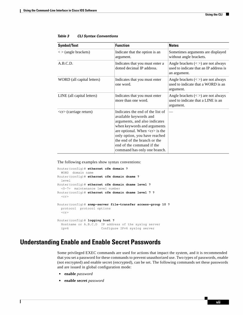
The following examples show syntax conventions:
Router(config)# ethernet cfm domain ? WORD domain nameRouter(config)# ethernet cfm domain dname ? level Router(config)# ethernet cfm domain dname level ? <0-7> maintenance level numberRouter(config)# ethernet cfm domain dname level 7 ? <cr>
Router(config)# snmp-server file-transfer access-group 10 ? protocol protocol options <cr>
Router(config)# logging host ? Hostname or A.B.C.D IP address of the syslog server ipv6 Configure IPv6 syslog server
Understanding Enable and Enable Secret PasswordsSome privileged EXEC commands are used for actions that impact the system, and it is recommended that you set a password for these commands to prevent unauthorized use. Two types of passwords, enable (not encrypted) and enable secret (encrypted), can be set. The following commands set these passwords and are issued in global configuration mode:
• enable password
• enable secret password
Table 3 CLI Syntax Conventions
Symbol/Text Function Notes
< > (angle brackets) Indicate that the option is an argument.
Sometimes arguments are displayed without angle brackets.
A.B.C.D. Indicates that you must enter a dotted decimal IP address.
Angle brackets (< >) are not always used to indicate that an IP address is an argument.
WORD (all capital letters) Indicates that you must enter one word.
Angle brackets (< >) are not always used to indicate that a WORD is an argument.
LINE (all capital letters) Indicates that you must enter more than one word.
Angle brackets (< >) are not always used to indicate that a LINE is an argument.
<cr> (carriage return) Indicates the end of the list of available keywords and arguments, and also indicates when keywords and arguments are optional. When <cr> is the only option, you have reached the end of the branch or the end of the command if the command has only one branch.
—

Using the Command-Line Interface in Cisco IOS SoftwareUsing the CLI
viii
Using an enable secret password is recommended because it is encrypted and more secure than the enable password. When you use an enable secret password, text is encrypted (unreadable) before it is written to the config.text file. When you use an enable password, the text is written as entered (readable) to the config.text file.
Each type of password is case sensitive, can contain from 1 to 25 uppercase and lowercase alphanumeric characters, and can start with a numeral. Spaces are also valid password characters; for example, “two words” is a valid password. Leading spaces are ignored, but trailing spaces are recognized.
Note Both password commands have numeric keywords that are single integer values. If you choose a numeral for the first character of your password followed by a space, the system will read the number as if it were the numeric keyword and not as part of your password.
When both passwords are set, the enable secret password takes precedence over the enable password.
To remove a password, use the no form of the commands: no enable password or no enable secret password.
For more information about password recovery procedures for Cisco products, see http://www.cisco.com/en/US/products/sw/iosswrel/ps1831/ products_tech_note09186a00801746e6.shtml.
Using the Command History FeatureThe command history feature saves, in a command history buffer, the commands that you enter during a session. The default number of saved commands is 10, but the number is configurable within the range of 0 to 256. This command history feature is particularly useful for recalling long or complex commands.
To change the number of commands saved in the history buffer for a terminal session, issue the terminal history size command:
Router# terminal history size num
A command history buffer is also available in line configuration mode with the same default and configuration options. To set the command history buffer size for a terminal session in line configuration mode, issue the history command:
Router(config-line)# history [size num]
To recall commands from the history buffer, use the following methods:
• Press Ctrl-P or the Up Arrow key—Recalls commands beginning with the most recent command. Repeat the key sequence to recall successively older commands.
• Press Ctrl-N or the Down Arrow key—Recalls the most recent commands in the history buffer after they have been recalled using Ctrl-P or the Up Arrow key. Repeat the key sequence to recall successively more recent commands.
Note The arrow keys function only on ANSI-compatible terminals such as the VT100.
• Issue the show history command in user EXEC or privileged EXEC mode—Lists the most recent commands that you entered. The number of commands that are displayed is determined by the setting of the terminal history size and history commands.
Using the Command-Line Interface in Cisco IOS SoftwareUsing the CLI
ix
The command history feature is enabled by default. To disable this feature for a terminal session, issue the terminal no history command in user EXEC or privileged EXEC mode or the no history command in line configuration mode.
Abbreviating CommandsTyping a complete command name is not always required for the command to execute. The CLI recognizes an abbreviated command when the abbreviation contains enough characters to uniquely identify the command. For example, the show version command can be abbreviated as sh ver. It cannot be abbreviated as s ver because s could mean show, set, or systat. The sh v abbreviation also is not valid because the show command has vrrp as a keyword in addition to version. (Command and keyword examples are from Cisco IOS Release 12.4(13)T.)
Using Aliases for CLI CommandsTo save time and the repetition of entering the same command multiple times, you can use a command alias. An alias can be configured to do anything that can be done at the command line, but an alias cannot move between modes, type in passwords, or perform any interactive functions.
Table 4 shows the default command aliases.
To create a command alias, issue the alias command in global configuration mode. The syntax of the command is alias mode command-alias original-command. Following are some examples:
• Router(config)# alias exec prt partition—privileged EXEC mode
• Router(config)# alias configure sb source-bridge—global configuration mode
• Router(config)# alias interface rl rate-limit—interface configuration mode
To view both default and user-created aliases, issue the show alias command.
For more information about the alias command, see http://www.cisco.com/en/US/docs/ios/fundamentals/command/reference/cf_a1.html.
Table 4 Default Command Aliases
Command Alias Original Command
h help
lo logout
p ping
s show
u or un undebug
w where
Using the Command-Line Interface in Cisco IOS SoftwareUsing the CLI
x
Using the no and default Forms of CommandsMost configuration commands have a no form that is used to reset a command to its default value or disable a feature or function. For example, the ip routing command is enabled by default. To disable this command, you would issue the no ip routing command. To re-enable IP routing, you would issue the ip routing command.
Configuration commands may also have a default form, which returns the command settings to their default values. For commands that are disabled by default, using the default form has the same effect as using the no form of the command. For commands that are enabled by default and have default settings, the default form enables the command and returns the settings to their default values.
The no form is documented in the command pages of command references. The default form is generally documented in the command pages only when the default form performs a different function than the plain and no forms of the command. To see what default commands are available on your system, enter default ? in the appropriate command mode.
Using the debug CommandA debug command produces extensive output that helps you troubleshoot problems in your network. These commands are available for many features and functions within Cisco IOS software. Some debug commands are debug all, debug aaa accounting, and debug mpls packets. To use debug commands during a Telnet session with a device, you must first enter the terminal monitor command. To turn off debugging completely, you must enter the undebug all command.
For more information about debug commands, see the Cisco IOS Debug Command Reference at http://www.cisco.com/en/US/docs/ios/debug/command/reference/db_book.html.
Caution Debugging is a high priority and high CPU utilization process that can render your device unusable. Use debug commands only to troubleshoot specific problems. The best times to run debugging are during periods of low network traffic and when few users are interacting with the network. Debugging during these periods decreases the likelihood that the debug command processing overhead will affect network performance or user access or response times.
Filtering Output Using Output ModifiersMany commands produce lengthy output that may use several screens to display. Using output modifiers, you can filter this output to show only the information that you want to see.
The following three output modifiers are available:
• begin regular-expression—Displays the first line in which a match of the regular expression is found and all lines that follow.
• include regular-expression—Displays all lines in which a match of the regular expression is found.
• exclude regular-expression—Displays all lines except those in which a match of the regular expression is found.
To use one of these output modifiers, type the command followed by the pipe symbol (|), the modifier, and the regular expression that you want to search for or filter. A regular expression is a case-sensitive alphanumeric pattern. It can be a single character or number, a phrase, or a more complex string.
Using the Command-Line Interface in Cisco IOS SoftwareSaving Changes to a Configuration
xi
The following example illustrates how to filter output of the show interface command to display only lines that include the expression “protocol.”
Router# show interface | include protocol
FastEthernet0/0 is up, line protocol is upSerial4/0 is up, line protocol is upSerial4/1 is up, line protocol is upSerial4/2 is administratively down, line protocol is downSerial4/3 is administratively down, line protocol is down
Understanding CLI Error MessagesYou may encounter some error messages while using the CLI. Table 5 shows the common CLI error messages.
For more system error messages, see the following document:
• Cisco IOS Release 12.4T System Message Guide
Saving Changes to a ConfigurationTo save changes that you made to the configuration of a device, you must issue the copy running-config startup-config command or the copy system:running-config nvram:startup-config command. When you issue these commands, the configuration changes that you made are saved to the startup configuration and saved when the software reloads or power to the device is turned off or interrupted. The following example shows the syntax of the copy running-config startup-config command:
Router# copy running-config startup-configDestination filename [startup-config]?
You press Enter to accept the startup-config filename (the default), or type a new filename and then press Enter to accept that name. The following output is displayed indicating that the configuration was saved.
Table 5 Common CLI Error Messages
Error Message Meaning How to Get Help
% Ambiguous command: “show con”
You did not enter enough characters for the command to be recognized.
Reenter the command followed by a space and a question mark (?). The keywords that you are allowed to enter for the command appear.
% Incomplete command. You did not enter all the keywords or values required by the command.
Reenter the command followed by a space and a question mark (?). The keywords that you are allowed to enter for the command appear.
% Invalid input detected at “^” marker.
You entered the command in-correctly. The caret (^) marks the point of the error.
Enter a question mark (?) to display all the commands that are available in this command mode. The keywords that you are allowed to enter for the command appear.
Using the Command-Line Interface in Cisco IOS SoftwareAdditional Information
xii
Building configuration...[OK]Router#
On most platforms, the configuration is saved to NVRAM. On platforms with a Class A flash file system, the configuration is saved to the location specified by the CONFIG_FILE environment variable. The CONFIG_FILE variable defaults to NVRAM.
Additional Information • “Using the Cisco IOS Command-Line Interface” section of the Cisco IOS Configuration
Fundamentals Configuration Guide
http://www.cisco.com/en/US/docs/ios/fundamentals/configuration/guide/cf_cli-basics.html
• Cisco Product/Technology Support
http://www.cisco.com/go/techdocs
• Support area on Cisco.com (also search for documentation by task or product)
http://www.cisco.com/en/US/support/index.html
• Software Download Center (downloads; tools; licensing, registration, advisory, and general information) (requires Cisco.com user ID and password)
http://www.cisco.com/kobayashi/sw-center/
• Error Message Decoder, a tool to help you research and resolve error messages for Cisco IOS software
http://www.cisco.com/pcgi-bin/Support/Errordecoder/index.cgi
• Command Lookup Tool, a tool to help you find detailed descriptions of Cisco IOS commands (requires Cisco.com user ID and password)
http://tools.cisco.com/Support/CLILookup
• Output Interpreter, a troubleshooting tool that analyzes command output of supported show commands
https://www.cisco.com/pcgi-bin/Support/OutputInterpreter/home.pl
CCDE, CCENT, CCSI, Cisco Eos, Cisco HealthPresence, Cisco IronPort, the Cisco logo, Cisco Lumin, Cisco Nexus, Cisco Nurse Connect, Cisco Pulse, Cisco StackPower, Cisco StadiumVision, Cisco TelePresence, Cisco Unified Computing System, Cisco WebEx, DCE, Flip Channels, Flip for Good, Flip Mino, Flipshare (Design), Flip Ultra, Flip Video, Flip Video (Design), Instant Broadband, and Welcome to the Human Network are trademarks; Changing the Way We Work, Live, Play, and Learn, Cisco Capital, Cisco Capital (Design), Cisco:Financed (Stylized), Cisco Store, and Flip Gift Card are service marks; and Access Registrar, Aironet, AllTouch, AsyncOS, Bringing the Meeting To You, Catalyst, CCDA, CCDP, CCIE, CCIP, CCNA, CCNP, CCSP, CCVP, Cisco, the Cisco Certified Internetwork Expert logo, Cisco IOS, Cisco Press, Cisco Systems, Cisco Systems Capital, the Cisco Systems logo, Cisco Unity, Collaboration Without Limitation, Continuum, EtherFast, EtherSwitch, Event Center, Explorer, Fast Step, Follow Me Browsing, FormShare, GainMaker, GigaDrive, HomeLink, iLYNX, Internet Quotient, IOS, iPhone, iQuick Study, IronPort, the IronPort logo, Laser Link, LightStream, Linksys, MediaTone, MeetingPlace, MeetingPlace Chime Sound, MGX, Networkers, Networking Academy, Network Registrar, PCNow, PIX, PowerKEY, PowerPanels, PowerTV, PowerTV (Design), PowerVu, Prisma, ProConnect, ROSA, ScriptShare, SenderBase, SMARTnet, Spectrum Expert, StackWise, The Fastest Way to Increase Your Internet Quotient, TransPath, WebEx, and the WebEx logo are registered trademarks of Cisco Systems, Inc. and/or its affiliates in the United States and certain other countries.
All other trademarks mentioned in this document or website are the property of their respective owners. The use of the word partner does not imply a partnership relationship between Cisco and any other company. (0908R)
Any Internet Protocol (IP) addresses and phone numbers used in this document are not intended to be actual addresses and phone numbers. Any examples, command display output, network topology diagrams, and other figures included in the document are shown for illustrative purposes only. Any use of actual IP addresses or phone numbers in illustrative content is unintentional and coincidental.
© 2008–2009 Cisco Systems, Inc. All rights reserved.
Americas Headquarters:Cisco Systems, Inc., 170 West Tasman Drive, San Jose, CA 95134-1706 USA
Configuring OSPF
This chapter describes how to configure Open Shortest Path First (OSPF). For a complete description of the OSPF commands in this chapter, refer to the “OSPF Commands” module in the Cisco IOS IP Routing Protocols Command Reference. To locate documentation of other commands that appear in this chapter, use the command reference master index, or search online.
OSPF is an Interior Gateway Protocol (IGP) developed by the OSPF working group of the Internet Engineering Task Force (IETF). Designed expressly for IP networks, OSPF supports IP subnetting and tagging of externally derived routing information. OSPF also allows packet authentication and uses IP multicast when sending and receiving packets.
We support RFC 1253, Open Shortest Path First (OSPF) MIB, August 1991. The OSPF MIB defines an IP routing protocol that provides management information related to OSPF and is supported by Cisco routers.
For protocol-independent features that work with OSPF, see the “Configuring IP Routing Protocol-Independent Features” module.
Finding Support Information for Platforms and Cisco IOS and Catalyst OS Software Images
Use Cisco Feature Navigator to find information about platform support and Cisco IOS and Catalyst OS software image support. To access Cisco Feature Navigator, go to http://www.cisco.com/go/cfn. An account on Cisco.com is not required.
The Cisco OSPF ImplementationThe Cisco implementation conforms to the OSPF Version 2 specifications detailed in the Internet RFC 2328. The list that follows outlines key features supported in the Cisco OSPF implementation:
• Stub areas—Definition of stub areas is supported.
• Route redistribution—Routes learned via any IP routing protocol can be redistributed into any other IP routing protocol. At the intradomain level, OSPF can import routes learned via Interior Gateway Routing Protocol (IGRP), Routing Information Protocol (RIP), and Intermediate System-to-Intermediate System (IS-IS). OSPF routes can also be exported into IGRP, RIP, and IS-IS. At the interdomain level, OSPF can import routes learned via Exterior Gateway Protocol (EGP) and Border Gateway Protocol (BGP). OSPF routes can be exported into BGP and EGP.
Configuring OSPF OSPF Configuration Task List
2
• Authentication—Plain text and Message Digest 5 (MD5) authentication among neighboring routers within an area is supported.
• Routing interface parameters—Configurable parameters supported include interface output cost, retransmission interval, interface transmit delay, router priority, router “dead” and hello intervals, and authentication key.
• Virtual links—Virtual links are supported.
• Not so stubby area (NSSA)—RFC 1587.
• OSPF over demand circuit—RFC 1793.
OSPF Configuration Task ListOSPF typically requires coordination among many internal routers: Area Border Routers (ABRs), which are routers connected to multiple areas, and Autonomous System Boundary Routers (ASBRs). At a minimum, OSPF-based routers or access servers can be configured with all default parameter values, no authentication, and interfaces assigned to areas. If you intend to customize your environment, you must ensure coordinated configurations of all routers.
In addition, you can specify route redistribution; see the task “Redistribute Routing Information” in the chapter “Configuring IP Routing Protocol-Independent Features” for information on how to configure route redistribution.
To configure OSPF, perform the tasks described in the following sections. The tasks in the first section are required; the tasks in the remaining sections are optional, but might be required for your application. For information about the maximum number of interfaces, see the “Configuration Limits” section.
• Enabling OSPF (Required)
• Configuring OSPF Interface Parameters (Optional)
• Configuring OSPF over Different Physical Networks (Optional)
• Configuring OSPF Area Parameters (Optional)
• Configuring OSPF NSSA (Optional)
• Configuring Route Summarization Between OSPF Areas (Optional)
• Configuring Route Summarization When Redistributing Routes into OSPF (Optional)
• Creating Virtual Links (Optional)
• Generating a Default Route (Optional)
• Configuring Lookup of DNS Names (Optional)
• Forcing the Router ID Choice with a Loopback Interface (Optional)
• Controlling Default Metrics (Optional)
• Changing the OSPF Administrative Distances (Optional)
• Configuring OSPF on Simplex Ethernet Interfaces (Optional)
• Configuring Route Calculation Timers (Optional)
• Configuring OSPF over On-Demand Circuits (Optional)
• Logging Neighbors Going Up or Down (Optional)
• Changing the LSA Group Pacing (Optional)
• Blocking OSPF LSA Flooding (Optional)
Configuring OSPF OSPF Configuration Task List
3
• Reducing LSA Flooding (Optional)
• Ignoring MOSPF LSA Packets (Optional)
• Displaying OSPF Update Packet Pacing (Optional)
• Monitoring and Maintaining OSPF (Optional)
• OSPF Configuration Examples (Optional)
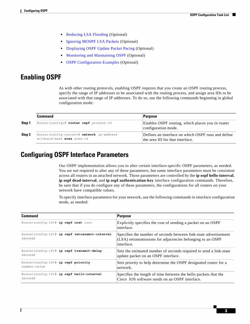
Enabling OSPFAs with other routing protocols, enabling OSPF requires that you create an OSPF routing process, specify the range of IP addresses to be associated with the routing process, and assign area IDs to be associated with that range of IP addresses. To do so, use the following commands beginning in global configuration mode:
Configuring OSPF Interface ParametersOur OSPF implementation allows you to alter certain interface-specific OSPF parameters, as needed. You are not required to alter any of these parameters, but some interface parameters must be consistent across all routers in an attached network. Those parameters are controlled by the ip ospf hello-interval, ip ospf dead-interval, and ip ospf authentication-key interface configuration commands. Therefore, be sure that if you do configure any of these parameters, the configurations for all routers on your network have compatible values.
To specify interface parameters for your network, use the following commands in interface configuration mode, as needed:
Command Purpose
Step 1 Router(config)# router ospf process-id Enables OSPF routing, which places you in router configuration mode.
Step 2 Router(config-router)# network ip-address wildcard-mask area area-id
Defines an interface on which OSPF runs and define the area ID for that interface.
Command Purpose
Router(config-if)# ip ospf cost cost Explicitly specifies the cost of sending a packet on an OSPF interface.
Router(config-if)# ip ospf retransmit-interval seconds
Specifies the number of seconds between link-state advertisement (LSA) retransmissions for adjacencies belonging to an OSPF interface.
Router(config-if)# ip ospf transmit-delay seconds
Sets the estimated number of seconds required to send a link-state update packet on an OSPF interface.
Router(config-if)# ip ospf priority number-value
Sets priority to help determine the OSPF designated router for a network.
Router(config-if)# ip ospf hello-interval seconds
Specifies the length of time between the hello packets that the Cisco IOS software sends on an OSPF interface.
Configuring OSPF OSPF Configuration Task List
4
Configuring OSPF over Different Physical NetworksOSPF classifies different media into the following three types of networks by default:
• Broadcast networks (Ethernet, Token Ring, and FDDI)
• Nonbroadcast multiaccess (NBMA) networks (Switched Multimegabit Data Service (SMDS), Frame Relay, and X.25)
• Point-to-point networks (High-Level Data Link Control [HDLC], PPP)
You can configure your network as either a broadcast or an NBMA network.
X.25 and Frame Relay provide an optional broadcast capability that can be configured in the map to allow OSPF to run as a broadcast network. Refer to the x25 map and frame-relay map command descriptions in the Cisco IOS Wide-Area Networking Command Reference publication for more detail.
Configuring Your OSPF Network Type
You have the choice of configuring your OSPF network type as either broadcast or NBMA, regardless of the default media type. Using this feature, you can configure broadcast networks as NBMA networks when, for example, you have routers in your network that do not support multicast addressing. You also can configure NBMA networks (such as X.25, Frame Relay, and SMDS) as broadcast networks. This feature saves you from needing to configure neighbors, as described in the section “Configuring OSPF for Nonbroadcast Networks” later in this chapter.
Configuring NBMA, multiaccess networks as either broadcast or nonbroadcast assumes that there are virtual circuits (VCs) from every router to every router or fully meshed network. This is not true for some cases, for example, because of cost constraints, or when you have only a partially meshed network. In these cases, you can configure the OSPF network type as a point-to-multipoint network. Routing between two routers not directly connected will go through the router that has VCs to both routers. Note that you need not configure neighbors when using this feature.
An OSPF point-to-multipoint interface is defined as a numbered point-to-point interface having one or more neighbors. It creates multiple host routes. An OSPF point-to-multipoint network has the following benefits compared to NBMA and point-to-point networks:
• Point-to-multipoint is easier to configure because it requires no configuration of neighbor commands, it consumes only one IP subnet, and it requires no designated router election.
• It costs less because it does not require a fully meshed topology.
Router(config-if)# ip ospf dead-interval seconds
Sets the number of seconds that a device must wait before it declares a neighbor OSPF router down because it has not received a hello packet.
Router(config-if)# ip ospf authentication-key key
Assigns a password to be used by neighboring OSPF routers on a network segment that is using the OSPF simple password authentication.
Router(config-if)# ip ospf message-digest-key key-id md5 key
Enables OSPF MD5 authentication. The values for the key-id and key arguments must match values specified for other neighbors on a network segment.
Router(config-if)# ip ospf authentication [message-digest | null]
Specifies the authentication type for an interface.
Command Purpose

Configuring OSPF OSPF Configuration Task List
5
• It is more reliable because it maintains connectivity in the event of VC failure.
To configure your OSPF network type, use the following command in interface configuration mode:
See the “OSPF Point-to-Multipoint Example” section at the end of this chapter for an example of an OSPF point-to-multipoint network.
Configuring Point-to-Multipoint, Broadcast Networks
On point-to-multipoint, broadcast networks, there is no need to specify neighbors. However, you can specify neighbors with the neighbor router configuration command, in which case you should specify a cost to that neighbor.
Before the point-to-multipoint keyword was added to the ip ospf network interface configuration command, some OSPF point-to-multipoint protocol traffic was treated as multicast traffic. Therefore, the neighbor router configuration command was not needed for point-to-multipoint interfaces because multicast took care of the traffic. Hello, update, and acknowledgment messages were sent using multicast. In particular, multicast hello messages discovered all neighbors dynamically.
On any point-to-multipoint interface (broadcast or not), the Cisco IOS software assumed that the cost to each neighbor was equal. The cost was configured with the ip ospf cost interface confutation command. In reality, the bandwidth to each neighbor is different, so the cost should differ. With this feature, you can configure a separate cost to each neighbor. This feature applies to point-to-multipoint interfaces only.
To treat an interface as point-to-multipoint broadcast and assign a cost to each neighbor, use the following commands beginning in interface configuration mode:
Repeat Step 4 for each neighbor if you want to specify a cost. Otherwise, neighbors will assume the cost of the interface, based on the ip ospf cost interface configuration command.
Configuring OSPF for Nonbroadcast Networks
Because many routers might be attached to an OSPF network, a designated router is selected for the network. Special configuration parameters are needed in the designated router selection if broadcast capability is not configured.
Command PurposeRouter(config-if)# ip ospf network {broadcast | non-broadcast | {point-to-multipoint [non-broadcast] | point-to-point}}
Configures the OSPF network type for a specified interface.
Command Purpose
Step 1 Router(config-if)# ip ospf network point-to-multipoint
Configures an interface as point-to-multipoint for broadcast media.
Step 2 Router(config-if)# exit Enters global configuration mode.
Step 3 Router(config)# router ospf process-id Configures an OSPF routing process and enters router configuration mode.
Step 4 Router(config-router)# neighbor ip-address cost number
Specifies a neighbor and assigns a cost to the neighbor.
Configuring OSPF OSPF Configuration Task List
6
These parameters need only be configured in those devices that are themselves eligible to become the designated router or backup designated router (in other words, routers with a nonzero router priority value).
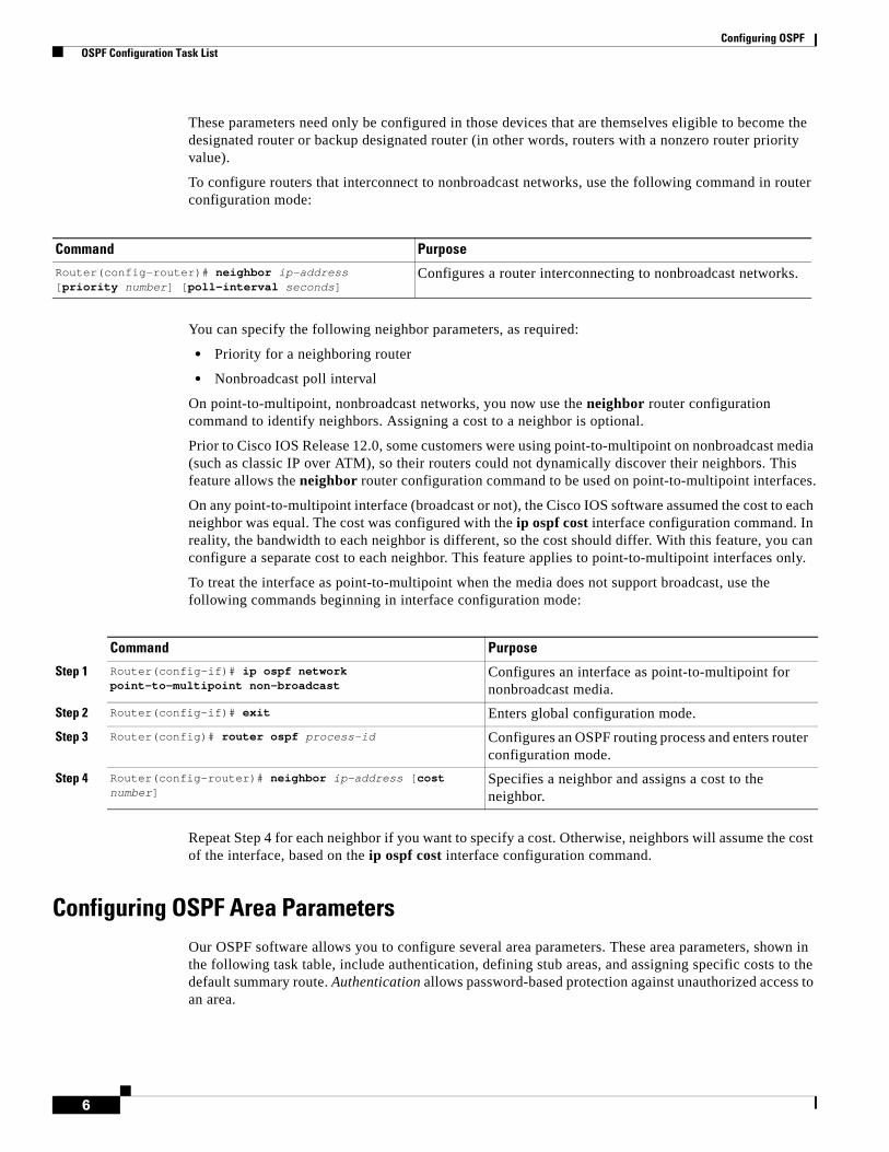
To configure routers that interconnect to nonbroadcast networks, use the following command in router configuration mode:
You can specify the following neighbor parameters, as required:
• Priority for a neighboring router
• Nonbroadcast poll interval
On point-to-multipoint, nonbroadcast networks, you now use the neighbor router configuration command to identify neighbors. Assigning a cost to a neighbor is optional.
Prior to Cisco IOS Release 12.0, some customers were using point-to-multipoint on nonbroadcast media (such as classic IP over ATM), so their routers could not dynamically discover their neighbors. This feature allows the neighbor router configuration command to be used on point-to-multipoint interfaces.
On any point-to-multipoint interface (broadcast or not), the Cisco IOS software assumed the cost to each neighbor was equal. The cost was configured with the ip ospf cost interface configuration command. In reality, the bandwidth to each neighbor is different, so the cost should differ. With this feature, you can configure a separate cost to each neighbor. This feature applies to point-to-multipoint interfaces only.
To treat the interface as point-to-multipoint when the media does not support broadcast, use the following commands beginning in interface configuration mode:
Repeat Step 4 for each neighbor if you want to specify a cost. Otherwise, neighbors will assume the cost of the interface, based on the ip ospf cost interface configuration command.
Configuring OSPF Area ParametersOur OSPF software allows you to configure several area parameters. These area parameters, shown in the following task table, include authentication, defining stub areas, and assigning specific costs to the default summary route. Authentication allows password-based protection against unauthorized access to an area.
Command PurposeRouter(config-router)# neighbor ip-address [priority number] [poll-interval seconds]
Configures a router interconnecting to nonbroadcast networks.
Command Purpose
Step 1 Router(config-if)# ip ospf network point-to-multipoint non-broadcast
Configures an interface as point-to-multipoint for nonbroadcast media.
Step 2 Router(config-if)# exit Enters global configuration mode.
Step 3 Router(config)# router ospf process-id Configures an OSPF routing process and enters router configuration mode.
Step 4 Router(config-router)# neighbor ip-address [cost number]
Specifies a neighbor and assigns a cost to the neighbor.
Configuring OSPF OSPF Configuration Task List
7
Stub areas are areas into which information on external routes is not sent. Instead, there is a default external route generated by the ABR, into the stub area for destinations outside the autonomous system. To take advantage of the OSPF stub area support, default routing must be used in the stub area. To further reduce the number of LSAs sent into a stub area, you can configure the no-summary keyword of the area stub router configuration command on the ABR to prevent it from sending summary link advertisement (LSAs Type 3) into the stub area.
To specify an area parameter for your network, use the following commands in router configuration mode as needed:
Configuring OSPF NSSAThe OSPF not-so-stubby area (NSSA) feature is described by RFC 1587 and was first integrated into Cisco IOS Release 11.2. OSPF NSSA is a nonproprietary extension of the existing OSPF stub area feature.
Use NSSA to simplify administration if you are an Internet service provider (ISP) or a network administrator that must connect a central site that is using OSPF to a remote site that is using a different routing protocol.
Prior to NSSA, the connection between the corporate site border router and the remote router could not be run as an OSPF stub area because routes for the remote site could not be redistributed into the stub area, and two routing protocols needed to be maintained. A simple protocol such as RIP was usually run and handled the redistribution. With NSSA, you can extend OSPF to cover the remote connection by defining the area between the corporate router and the remote router as an NSSA.
As with OSPF stub areas, NSSA areas cannot be injected with distributed routes via Type 5 LSAs. Route redistribution into an NSSA area is possible only with a special type of link-state advertisement (LSA) that is known as Type 7 that can exist only in an NSSA area. An NSSA autonomous system boundary router (ASBR) generates the Type 7 LSA so that the routes can be redistributed, and an NSSA area border router (ABR) translates the Type 7 LSA into a Type 5 LSA, which can be flooded throughout the whole OSPF routing domain. Summarization and filtering are supported during the translation.
Figure 1 shows a network diagram in which OSPF Area 1 is defined as the stub area. The EIGRP routes cannot be propagated into the OSPF domain because routing redistribution is not allowed in the stub area. However, once OSPF Area 1 is defined as an NSSA, an NSSA ASBR can inject the EIGRP routes into the OSPF NSSA by creating Type 7 LSAs.
Command PurposeRouter(config-router)# area area-id authentication Enables authentication for an OSPF area.
Router(config-router)# area area-id authentication message-digest
Enables MD5 authentication for an OSPF area.
Router(config-router)# area area-id stub [no-summary]
Defines an area to be a stub area.
Router(config-router)# area area-id default-cost cost
Assigns a specific cost to the default summary route used for the stub area.
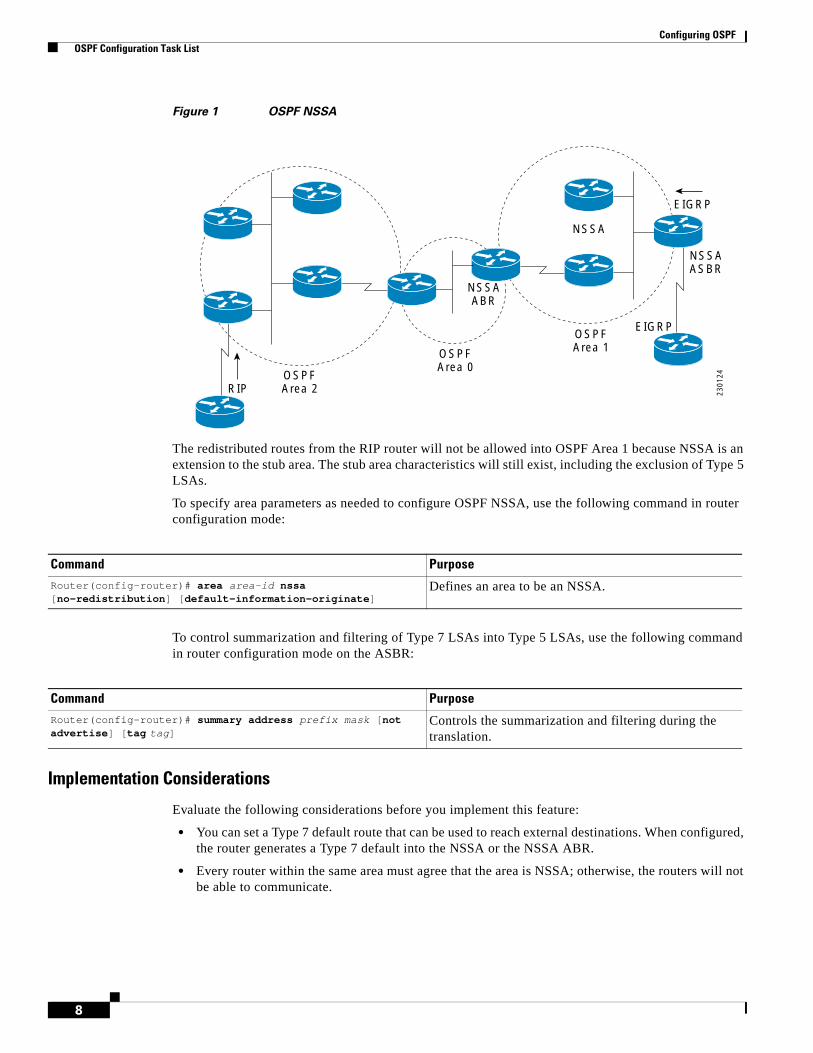
Configuring OSPF OSPF Configuration Task List
8
Figure 1 OSPF NSSA
The redistributed routes from the RIP router will not be allowed into OSPF Area 1 because NSSA is an extension to the stub area. The stub area characteristics will still exist, including the exclusion of Type 5 LSAs.
To specify area parameters as needed to configure OSPF NSSA, use the following command in router configuration mode:
To control summarization and filtering of Type 7 LSAs into Type 5 LSAs, use the following command in router configuration mode on the ASBR:
Implementation Considerations
Evaluate the following considerations before you implement this feature:
• You can set a Type 7 default route that can be used to reach external destinations. When configured, the router generates a Type 7 default into the NSSA or the NSSA ABR.
• Every router within the same area must agree that the area is NSSA; otherwise, the routers will not be able to communicate.
NSSA
NSSAABR
RIP
EIGRP
NSSAASBR
EIGRP
OSPFArea 2
OSPFArea 0
OSPFArea 1
2301
24
Command Purpose
Router(config-router)# area area-id nssa [no-redistribution] [default-information-originate]
Defines an area to be an NSSA.
Command Purpose
Router(config-router)# summary address prefix mask [not advertise] [tag tag]
Controls the summarization and filtering during the translation.
Configuring OSPF OSPF Configuration Task List
9
Configuring Route Summarization Between OSPF AreasRoute summarization is the consolidation of advertised addresses. This feature causes a single summary route to be advertised to other areas by an ABR. In OSPF, an ABR will advertise networks in one area into another area. If the network numbers in an area are assigned in a way such that they are contiguous, you can configure the ABR to advertise a summary route that covers all the individual networks within the area that fall into the specified range.
To specify an address range, use the following command in router configuration mode:
Configuring Route Summarization When Redistributing Routes into OSPFWhen routes from other protocols are redistributed into OSPF (as described in the chapter “Configuring IP Routing Protocol-Independent Features”), each route is advertised individually in an external LSA. However, you can configure the Cisco IOS software to advertise a single route for all the redistributed routes that are covered by a specified network address and mask. Doing so helps decrease the size of the OSPF link-state database.
To have the software advertise one summary route for all redistributed routes covered by a network address and mask, use the following command in router configuration mode:
Creating Virtual LinksIn OSPF, all areas must be connected to a backbone area. If there is a break in backbone continuity, or the backbone is purposefully partitioned, you can establish a virtual link. The two endpoints of a virtual link are ABRs. The virtual link must be configured in both routers. The configuration information in each router consists of the other virtual endpoint (the other ABR) and the nonbackbone area that the two routers have in common (called the transit area). Note that virtual links cannot be configured through stub areas.
To establish a virtual link, use the following command in router configuration mode:
Command PurposeRouter(config-router)# area area-id range ip-address mask [advertise | not-advertise][cost cost]
Specifies an address range for which a single route will be advertised.
Command Purpose
Router(config-router)# summary-address {{ip-address mask} | {prefix mask}} [not-advertise][tag tag]
Specifies an address and mask that covers redistributed routes, so only one summary route is advertised. Use the optional not-advertise keyword to filter out a set of routes.
Command Purpose
Router(config-router)# area area-id virtual-link router-id [authentication [message-digest | null]] [hello-interval seconds] [retransmit-interval seconds] [transmit-delay seconds] [dead-interval seconds] [[authentication-key key] | [message-digest-key key-id md5 key]]
Establishes a virtual link.
Configuring OSPF OSPF Configuration Task List
10
To display information about virtual links, use the show ip ospf virtual-links EXEC command. To display the router ID of an OSPF router, use the show ip ospf EXEC command.
Generating a Default RouteYou can force an ASBR to generate a default route into an OSPF routing domain. Whenever you specifically configure redistribution of routes into an OSPF routing domain, the router automatically becomes an ASBR. However, an ASBR does not, by default, generate a default route into the OSPF routing domain.
To force the ASBR to generate a default route, use the following command in router configuration mode:
For a discussion of redistribution of routes, see the “Configuring IP Routing Protocol-Independent Features” chapter.
Configuring Lookup of DNS NamesYou can configure OSPF to look up Domain Naming System (DNS) names for use in all OSPF show EXEC command displays. This feature makes it easier to identify a router, because the router is displayed by name rather than by its router ID or neighbor ID.
To configure DNS name lookup, use the following command in global configuration mode:
Forcing the Router ID Choice with a Loopback InterfaceOSPF uses the largest IP address configured on the interfaces as its router ID. If the interface associated with this IP address is ever brought down, or if the address is removed, the OSPF process must recalculate a new router ID and resend all its routing information out its interfaces.
If a loopback interface is configured with an IP address, the Cisco IOS software will use this IP address as its router ID, even if other interfaces have larger IP addresses. Because loopback interfaces never go down, greater stability in the routing table is achieved.
Command PurposeRouter(config-router)# default-information originate [always] [metric metric-value] [metric-type type-value] [route-map map-name]
Forces the autonomous system boundary router to generate a default route into the OSPF routing domain.
Note The always keyword includes the following exception when the route map is used. When a route map is used, the origination of the default route by OSPF is not bound to the existence of a default route in the routing table.
Command Purpose
Router(config)# ip ospf name-lookup Configures DNS name lookup.
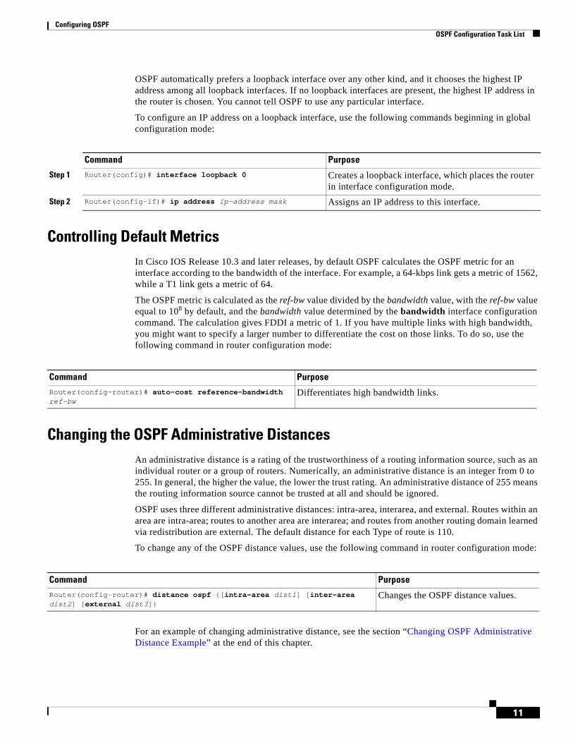
Configuring OSPF OSPF Configuration Task List
11
OSPF automatically prefers a loopback interface over any other kind, and it chooses the highest IP address among all loopback interfaces. If no loopback interfaces are present, the highest IP address in the router is chosen. You cannot tell OSPF to use any particular interface.
To configure an IP address on a loopback interface, use the following commands beginning in global configuration mode:
Controlling Default MetricsIn Cisco IOS Release 10.3 and later releases, by default OSPF calculates the OSPF metric for an interface according to the bandwidth of the interface. For example, a 64-kbps link gets a metric of 1562, while a T1 link gets a metric of 64.
The OSPF metric is calculated as the ref-bw value divided by the bandwidth value, with the ref-bw value equal to 108 by default, and the bandwidth value determined by the bandwidth interface configuration command. The calculation gives FDDI a metric of 1. If you have multiple links with high bandwidth, you might want to specify a larger number to differentiate the cost on those links. To do so, use the following command in router configuration mode:
Changing the OSPF Administrative DistancesAn administrative distance is a rating of the trustworthiness of a routing information source, such as an individual router or a group of routers. Numerically, an administrative distance is an integer from 0 to 255. In general, the higher the value, the lower the trust rating. An administrative distance of 255 means the routing information source cannot be trusted at all and should be ignored.
OSPF uses three different administrative distances: intra-area, interarea, and external. Routes within an area are intra-area; routes to another area are interarea; and routes from another routing domain learned via redistribution are external. The default distance for each Type of route is 110.
To change any of the OSPF distance values, use the following command in router configuration mode:
For an example of changing administrative distance, see the section “Changing OSPF Administrative Distance Example” at the end of this chapter.
Command Purpose
Step 1 Router(config)# interface loopback 0 Creates a loopback interface, which places the router in interface configuration mode.
Step 2 Router(config-if)# ip address ip-address mask Assigns an IP address to this interface.
Command Purpose
Router(config-router)# auto-cost reference-bandwidth ref-bw
Differentiates high bandwidth links.
Command Purpose
Router(config-router)# distance ospf {[intra-area dist1] [inter-area dist2] [external dist3]}
Changes the OSPF distance values.
Configuring OSPF OSPF Configuration Task List
12
Configuring OSPF on Simplex Ethernet InterfacesBecause simplex interfaces between two devices on an Ethernet represent only one network segment, for OSPF you must configure the sending interface to be a passive interface. This configuration prevents OSPF from sending hello packets for the sending interface. Both devices are able to see each other via the hello packet generated for the receiving interface.
To configure OSPF on simplex Ethernet interfaces, use the following command in router configuration mode:
Configuring Route Calculation TimersYou can configure the delay time between when OSPF receives a topology change and when it starts a shortest path first (SPF) calculation. You can also configure the hold time between two consecutive SPF calculations. To do so, use the following command in router configuration mode:
Configuring OSPF over On-Demand CircuitsThe OSPF on-demand circuit is an enhancement to the OSPF protocol that allows efficient operation over on-demand circuits like ISDN, X.25 switched virtual circuits (SVCs), and dialup lines. This feature supports RFC 1793, Extending OSPF to Support Demand Circuits.
Prior to this feature, OSPF periodic hello and LSA updates would be exchanged between routers that connected the on-demand link, even when no changes occurred in the hello or LSA information.
With this feature, periodic hellos are suppressed and the periodic refreshes of LSAs are not flooded over the demand circuit. These packets bring up the link only when they are exchanged for the first time, or when a change occurs in the information they contain. This operation allows the underlying data link layer to be closed when the network topology is stable.
This feature is useful when you want to connect telecommuters or branch offices to an OSPF backbone at a central site. In this case, OSPF for on-demand circuits allows the benefits of OSPF over the entire domain, without excess connection costs. Periodic refreshes of hello updates, LSA updates, and other protocol overhead are prevented from enabling the on-demand circuit when there is no “real” data to send.
Overhead protocols such as hellos and LSAs are transferred over the on-demand circuit only upon initial setup and when they reflect a change in the topology. This means that critical changes to the topology that require new SPF calculations are sent in order to maintain network topology integrity. Periodic refreshes that do not include changes, however, are not sent across the link.
To configure OSPF for on-demand circuits, use the following commands beginning in global configuration mode:
Command PurposeRouter(config-router)# passive-interface interface-type interface-number
Suppresses the sending of hello packets through the specified interface.
Command Purpose
Router(config-router)# timers spf spf-delay spf-holdtime
Configures route calculation timers.
Configuring OSPF OSPF Configuration Task List
13
If the router is part of a point-to-point topology, then only one end of the demand circuit must be configured with this command. However, all routers must have this feature loaded.
If the router is part of a point-to-multipoint topology, only the multipoint end must be configured with this command.
For an example of OSPF over an on-demand circuit, see the section “OSPF over On-Demand Routing Example” at the end of this chapter.
Implementation Considerations
Evaluate the following considerations before implementing this feature:
• Because LSAs that include topology changes are flooded over an on-demand circuit, we recommend that you put demand circuits within OSPF stub areas or within NSSAs to isolate the demand circuits from as many topology changes as possible.
• To take advantage of the on-demand circuit functionality within a stub area or NSSA, every router in the area must have this feature loaded. If this feature is deployed within a regular area, all other regular areas must also support this feature before the demand circuit functionality can take effect because Type 5 external LSAs are flooded throughout all areas.
• Hub-and-spoke network topologies that have a point-to-multipoint (p2mp) OSPF interface type on a hub might not revert back to non-demand circuit mode when needed. You must simultaneously reconfigure OSPF on all interfaces on the p2mp segment when reverting them from demand circuit mode to non-demand circuit mode.
• Do not implement this feature on a broadcast-based network topology because the overhead protocols (such as hello and LSA packets) cannot be successfully suppressed, which means the link will remain up.
• Configuring the router for an OSPF on-demand circuit with an asynchronous interface is not a supported configuration. The supported configuration is to use dialer interfaces on both ends of the circuit. For more information, refer to the following TAC URL:
http://www.cisco.com/warp/public/104/dcprob.html#reason5
Logging Neighbors Going Up or DownBy default, the system sends a syslog message when an OSPF neighbor goes up or down. If you turned off this feature and want to restore it, use the following command in router configuration mode:
Command Purpose
Step 1 Router(config)# router ospf process-id Enables OSPF operation.
Step 2 Router(config)# interface interface-type interface-number
Enters interface configuration mode.
Step 3 Router(config-if)# ip ospf demand-circuit Configures OSPF on an on-demand circuit.
Command PurposeRouter(config-router)# log-adjacency-changes [detail]
Sends syslog message when an OSPF neighbor goes up or down.
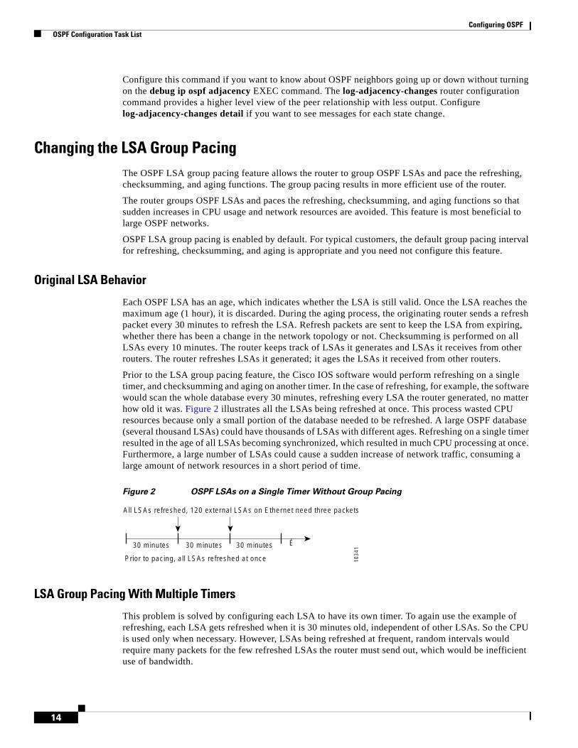
Configuring OSPF OSPF Configuration Task List
14
Configure this command if you want to know about OSPF neighbors going up or down without turning on the debug ip ospf adjacency EXEC command. The log-adjacency-changes router configuration command provides a higher level view of the peer relationship with less output. Configure log-adjacency-changes detail if you want to see messages for each state change.
Changing the LSA Group PacingThe OSPF LSA group pacing feature allows the router to group OSPF LSAs and pace the refreshing, checksumming, and aging functions. The group pacing results in more efficient use of the router.
The router groups OSPF LSAs and paces the refreshing, checksumming, and aging functions so that sudden increases in CPU usage and network resources are avoided. This feature is most beneficial to large OSPF networks.
OSPF LSA group pacing is enabled by default. For typical customers, the default group pacing interval for refreshing, checksumming, and aging is appropriate and you need not configure this feature.
Original LSA Behavior
Each OSPF LSA has an age, which indicates whether the LSA is still valid. Once the LSA reaches the maximum age (1 hour), it is discarded. During the aging process, the originating router sends a refresh packet every 30 minutes to refresh the LSA. Refresh packets are sent to keep the LSA from expiring, whether there has been a change in the network topology or not. Checksumming is performed on all LSAs every 10 minutes. The router keeps track of LSAs it generates and LSAs it receives from other routers. The router refreshes LSAs it generated; it ages the LSAs it received from other routers.
Prior to the LSA group pacing feature, the Cisco IOS software would perform refreshing on a single timer, and checksumming and aging on another timer. In the case of refreshing, for example, the software would scan the whole database every 30 minutes, refreshing every LSA the router generated, no matter how old it was. Figure 2 illustrates all the LSAs being refreshed at once. This process wasted CPU resources because only a small portion of the database needed to be refreshed. A large OSPF database (several thousand LSAs) could have thousands of LSAs with different ages. Refreshing on a single timer resulted in the age of all LSAs becoming synchronized, which resulted in much CPU processing at once. Furthermore, a large number of LSAs could cause a sudden increase of network traffic, consuming a large amount of network resources in a short period of time.
Figure 2 OSPF LSAs on a Single Timer Without Group Pacing
LSA Group Pacing With Multiple Timers
This problem is solved by configuring each LSA to have its own timer. To again use the example of refreshing, each LSA gets refreshed when it is 30 minutes old, independent of other LSAs. So the CPU is used only when necessary. However, LSAs being refreshed at frequent, random intervals would require many packets for the few refreshed LSAs the router must send out, which would be inefficient use of bandwidth.
30 minutes 30 minutes 30 minutes
Prior to pacing, all LSAs refreshed at once
All LSAs refreshed, 120 external LSAs on Ethernet need three packets
1034
1
É
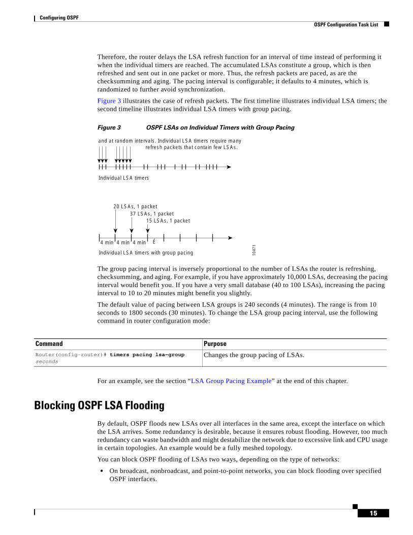
Configuring OSPF OSPF Configuration Task List
15
Therefore, the router delays the LSA refresh function for an interval of time instead of performing it when the individual timers are reached. The accumulated LSAs constitute a group, which is then refreshed and sent out in one packet or more. Thus, the refresh packets are paced, as are the checksumming and aging. The pacing interval is configurable; it defaults to 4 minutes, which is randomized to further avoid synchronization.
Figure 3 illustrates the case of refresh packets. The first timeline illustrates individual LSA timers; the second timeline illustrates individual LSA timers with group pacing.
Figure 3 OSPF LSAs on Individual Timers with Group Pacing
The group pacing interval is inversely proportional to the number of LSAs the router is refreshing, checksumming, and aging. For example, if you have approximately 10,000 LSAs, decreasing the pacing interval would benefit you. If you have a very small database (40 to 100 LSAs), increasing the pacing interval to 10 to 20 minutes might benefit you slightly.
The default value of pacing between LSA groups is 240 seconds (4 minutes). The range is from 10 seconds to 1800 seconds (30 minutes). To change the LSA group pacing interval, use the following command in router configuration mode:
For an example, see the section “LSA Group Pacing Example” at the end of this chapter.
Blocking OSPF LSA FloodingBy default, OSPF floods new LSAs over all interfaces in the same area, except the interface on which the LSA arrives. Some redundancy is desirable, because it ensures robust flooding. However, too much redundancy can waste bandwidth and might destabilize the network due to excessive link and CPU usage in certain topologies. An example would be a fully meshed topology.
You can block OSPF flooding of LSAs two ways, depending on the type of networks:
• On broadcast, nonbroadcast, and point-to-point networks, you can block flooding over specified OSPF interfaces.
4 min
Individual LSA timers with group pacing
20 LSAs, 1 packet
15 LSAs, 1 packet
1047
1
37 LSAs, 1 packet
4 min 4 min É
Individual LSA timers
and at random intervals. Individual LSA timers require manyrefresh packets that contain few LSAs.
Command Purpose
Router(config-router)# timers pacing lsa-group seconds
Changes the group pacing of LSAs.
Configuring OSPF OSPF Configuration Task List
16
• On point-to-multipoint networks, you can block flooding to a specified neighbor.
On broadcast, nonbroadcast, and point-to-point networks, to prevent flooding of OSPF LSAs, use the following command in interface configuration mode:
On point-to-multipoint networks, to prevent flooding of OSPF LSAs, use the following command in router configuration mode:
For an example of blocking LSA flooding, see the section “Block LSA Flooding Example” at the end of this chapter.
Reducing LSA FloodingThe explosive growth of the Internet has placed the focus on the scalability of IGPs such as OSPF. By design, OSPF requires LSAs to be refreshed as they expire after 3600 seconds. Some implementations have tried to improve the flooding by reducing the frequency to refresh from 30 minutes to about 50 minutes. This solution reduces the amount of refresh traffic but requires at least one refresh before the LSA expires. The OSPF flooding reduction solution works by reducing unnecessary refreshing and flooding of already known and unchanged information. To achieve this reduction, the LSAs are now flooded with the higher bit set. The LSAs are now set as “do not age.”
To reduce unnecessary refreshing and flooding of LSAs on your network, use the following command in interface configuration mode:
Ignoring MOSPF LSA PacketsCisco routers do not support LSA Type 6 Multicast OSPF (MOSPF), and they generate syslog messages if they receive such packets. If the router is receiving many MOSPF packets, you might want to configure the router to ignore the packets and thus prevent a large number of syslog messages. To do so, use the following command in router configuration mode:
Command Purpose
Router(config-if)# ip ospf database-filter all out
Blocks the flooding of OSPF LSA packets to the interface.
Command Purpose
Router(config-router)# neighbor ip-address database-filter all out
Blocks the flooding of OSPF LSA packets to the specified neighbor.
Command Purpose
Router(config-if)# ip ospf flood-reduction Suppresses the unnecessary flooding of LSAs in stable topologies.
Command Purpose
Router(config-router)# ignore lsa mospf Prevents the router from generating syslog messages when it receives MOSPF LSA packets.
Configuring OSPF OSPF Configuration Task List
17
For an example of suppressing MOSPF LSA packets, see the section “Ignore MOSPF LSA Packets Example” at the end of this chapter.
Displaying OSPF Update Packet PacingThe former OSPF implementation for sending update packets needed to be more efficient. Some update packets were getting lost in cases where the link was slow, a neighbor could not receive the updates quickly enough, or the router was out of buffer space. For example, packets might be dropped if either of the following topologies existed:
• A fast router was connected to a slower router over a point-to-point link.
• During flooding, several neighbors sent updates to a single router at the same time.
OSPF update packets are now automatically paced so they are not sent less than 33 milliseconds apart. Pacing is also added between resends to increase efficiency and minimize lost retransmissions. Also, you can display the LSAs waiting to be sent out an interface. The benefit of the pacing is that OSPF update and retransmission packets are sent more efficiently.
There are no configuration tasks for this feature; it occurs automatically.
To observe OSPF packet pacing by displaying a list of LSAs waiting to be flooded over a specified interface, use the following command in EXEC mode:
Monitoring and Maintaining OSPFYou can display specific statistics such as the contents of IP routing tables, caches, and databases. Information provided can be used to determine resource utilization and solve network problems. You can also display information about node reachability and discover the routing path that your device packets are taking through the network.
To display various routing statistics, use the following commands in EXEC mode, as needed:
Command PurposeRouter# show ip ospf flood-list interface-type interface-number
Displays a list of LSAs waiting to be flooded over an interface.
Command Purpose
Router# show ip ospf [process-id] Displays general information about OSPF routing processes.
Router# show ip ospf border-routers Displays the internal OSPF routing table entries to the ABR and ASBR.

Configuring OSPF OSPF Configuration Task List
18
To restart an OSPF process, use the following command in EXEC mode:
Router# show ip ospf [process-id [area-id]] database
Router# show ip ospf [process-id [area-id]] database [database-summary]
Router# show ip ospf [process-id [area-id]] database [router] [self-originate]
Router# show ip ospf [process-id [area-id]] database [router] [adv-router [ip-address]]
Router# show ip ospf [process-id [area-id]] database [router] [link-state-id]
Router# show ip ospf [process-id [area-id]] database [network] [link-state-id]
Router# show ip ospf [process-id [area-id]] database [summary] [link-state-id]
Router# show ip ospf [process-id [area-id]] database [asbr-summary] [link-state-id]
Router# show ip ospf [process-id [area-id]] database [external] [link-state-id]
Router# show ip ospf [process-id [area-id]] database [nssa-external] [link-state-id]
Router# show ip ospf [process-id [area-id]] database [opaque-link] [link-state-id]
Router# show ip ospf [process-id [area-id]] database [opaque-area] [link-state-id]
Router# show ip ospf [process-id [area-id]] database [opaque-as] [link-state-id]
Displays lists of information related to the OSPF database.
Router# show ip ospf flood-list interface interface-type
Displays a list of LSAs waiting to be flooded over an interface (to observe OSPF packet pacing).
Router# show ip ospf interface [interface-type interface-number]
Displays OSPF-related interface information.
Router# show ip ospf neighbor [interface-name] [neighbor-id] detail
Displays OSPF neighbor information on a per-interface basis.
Router# show ip ospf request-list [neighbor] [interface] [interface-neighbor]
Displays a list of all LSAs requested by a router.
Router# show ip ospf retransmission-list [neighbor] [interface] [interface-neighbor]
Displays a list of all LSAs waiting to be resent.
Router# show ip ospf [process-id]summary-address Displays a list of all summary address redistribution information configured under an OSPF process.
Router# show ip ospf virtual-links Displays OSPF-related virtual links information.
Command Purpose
Configuring OSPF OSPF Configuration Task List
19
Configuration LimitsOn systems with a large number of interfaces, it may be possible to configure OSPF such that the number of links advertised in the router link-state advertisement (LSA) causes the link state update packet to exceed the size of a “huge” IOS buffer. To resolve this problem, reduce the number of OSPF links or increase the huge buffer size by entering the following command: buffers huge size size.
A link state update packet containing a router LSA typically has a fixed overhead of 196 bytes, and an additional 12 bytes are required for each link description. With a huge buffer size of 18024 bytes there can be a maximum of 1485 link descriptions.
Since the maximum size of an IP packet is 65535 bytes, there is still an upper bound on the number of links possible on a router.
OSPF Configuration ExamplesThe following sections provide OSPF configuration examples:
• OSPF Point-to-Multipoint Example
• OSPF Point-to-Multipoint, Broadcast Example
• OSPF Point-to-Multipoint, Nonbroadcast Example
• Variable-Length Subnet Masks Example
• OSPF NSSA Example
• OSPF Routing and Route Redistribution Examples
• Route Map Examples
• Changing OSPF Administrative Distance Example
• OSPF over On-Demand Routing Example
• LSA Group Pacing Example
• Block LSA Flooding Example
• Ignore MOSPF LSA Packets Example
OSPF Point-to-Multipoint ExampleIn Figure 4, the router named Mollie uses data-link connection identifier (DLCI) 201 to communicate with the router named Neon, DLCI 202 to the router named Jelly, and DLCI 203 to the router named Platty. Neon uses DLCI 101 to communicate with Mollie and DLCI 102 to communicate with Platty. Platty communicates with Neon (DLCI 401) and Mollie (DLCI 402). Jelly communicates with Mollie (DLCI 301). Configuration examples follow the figure.
Command PurposeRouter# clear ip ospf [pid] {process | redistribution | counters [neighbor [neighbor-interface] [neighbor-id]]}
Clears redistribution based on the OSPF routing process ID. If the pid option is not specified, all OSPF processes are cleared.

Configuring OSPF OSPF Configuration Task List
20
Figure 4 OSPF Point-to-Multipoint Example
Mollie Configurationhostname mollie!interface serial 1ip address 10.0.0.2 255.0.0.0ip ospf network point-to-multipointencapsulation frame-relayframe-relay map ip 10.0.0.1 201 broadcastframe-relay map ip 10.0.0.3 202 broadcastframe-relay map ip 10.0.0.4 203 broadcast
!router ospf 1network 10.0.0.0 0.0.0.255 area 0
Neon Configurationhostname neon!interface serial 0ip address 10.0.0.1 255.0.0.0ip ospf network point-to-multipointencapsulation frame-relayframe-relay map ip 10.0.0.2 101 broadcastframe-relay map ip 10.0.0.4 102 broadcast
!router ospf 1network 10.0.0.0 0.0.0.255 area 0
Platty Configurationhostname platty!interface serial 3ip address 10.0.0.4 255.0.0.0ip ospf network point-to-multipointencapsulation frame-relayclock rate 1000000frame-relay map ip 10.0.0.1 401 broadcastframe-relay map ip 10.0.0.2 402 broadcast
!router ospf 1network 10.0.0.0 0.0.0.255 area 0
Jelly Configurationhostname jelly
Mollie
Neon10.0.0.1
Platty10.0.0.4
Jelly
301
202
201
203
101
402
401
102
5662
1
Configuring OSPF OSPF Configuration Task List
21
!interface serial 2ip address 10.0.0.3 255.0.0.0ip ospf network point-to-multipointencapsulation frame-relayclock rate 2000000frame-relay map ip 10.0.0.2 301 broadcast
!router ospf 1network 10.0.0.0 0.0.0.255 area 0
OSPF Point-to-Multipoint, Broadcast ExampleThe following example illustrates a point-to-multipoint network with broadcast:
interface Serial0 ip address 10.0.1.1 255.255.255.0 encapsulation frame-relayip ospf cost 100
ip ospf network point-to-multipoint frame-relay map ip 10.0.1.3 202 broadcast frame-relay map ip 10.0.1.4 203 broadcast frame-relay map ip 10.0.1.5 204 broadcast frame-relay local-dlci 200!router ospf 1 network 10.0.1.0 0.0.0.255 area 0 neighbor 10.0.1.5 cost 5 neighbor 10.0.1.4 cost 10
The following example shows the configuration of the neighbor at 10.0.1.3:
interface serial 0ip address 10.0.1.3 255.255.255.0ip ospf network point-to-multipointencapsulation frame-relayframe-relay local-dlci 301frame-relay map ip 10.0.1.1 300 broadcastno shut
!router ospf 1network 10.0.1.0 0.0.0.255 area 0
The output shown for neighbors in the first configuration is as follows:
Router# show ip ospf neighborNeighbor ID Pri State Dead Time Address Interface172.16.1.1 1 FULL/ - 00:01:50 10.0.1.5 Serial0172.16.1.4 1 FULL/ - 00:01:47 10.0.1.4 Serial0172.16.1.8 1 FULL/ - 00:01:45 10.0.1.3 Serial0
The route information in the first configuration is as follows:
Router# show ip routeCodes: C - connected, S - static, I - IGRP, R - RIP, M - mobile, B - BGP D - EIGRP, EX - EIGRP external, O - OSPF, IA - OSPF inter area N1 - OSPF NSSA external type 1, N2 - OSPF NSSA external type 2 E1 - OSPF external type 1, E2 - OSPF external type 2, E - EGP i - IS-IS, L1 - IS-IS level-1, L2 - IS-IS level-2, * - candidate default U - per-user static route, o - ODRGateway of last resort is not setC 1.0.0.0/8 is directly connected, Loopback0 10.0.0.0/8 is variably subnetted, 4 subnets, 2 masks
Configuring OSPF OSPF Configuration Task List
22
O 10.0.1.3/32 [110/100] via 10.0.1.3, 00:39:08, Serial0C 10.0.1.0/24 is directly connected, Serial0O 10.0.1.5/32 [110/5] via 10.0.1.5, 00:39:08, Serial0O 10.0.1.4/32 [110/10] via 10.0.1.4, 00:39:08, Serial0
OSPF Point-to-Multipoint, Nonbroadcast ExampleThe following example illustrates a point-to-multipoint network with nonbroadcast:
interface Serial0ip address 10.0.1.1 255.255.255.0ip ospf network point-to-multipoint non-broadcastencapsulation frame-relayno keepaliveframe-relay local-dlci 200frame-relay map ip 10.0.1.3 202frame-relay map ip 10.0.1.4 203frame-relay map ip 10.0.1.5 204no shut!router ospf 1network 10.0.1.0 0.0.0.255 area 0neighbor 10.0.1.3 cost 5neighbor 10.0.1.4 cost 10neighbor 10.0.1.5 cost 15
The following example is the configuration for the router on the other side:
interface Serial9/2 ip address 10.0.1.3 255.255.255.0 encapsulation frame-relay ip ospf network point-to-multipoint non-broadcast no ip mroute-cache no keepalive no fair-queue frame-relay local-dlci 301 frame-relay map ip 10.0.1.1 300 no shut ! router ospf 1 network 10.0.1.0 0.0.0.255 area 0
The output shown for neighbors in the first configuration is as follows:
Router# show ip ospf neighborNeighbor ID Pri State Dead Time Address Interface172.16.1.1 1 FULL/ - 00:01:52 10.0.1.5 Serial0172.16.1.4 1 FULL/ - 00:01:52 10.0.1.4 Serial0172.16.1.8 1 FULL/ - 00:01:52 10.0.1.3 Serial0
Variable-Length Subnet Masks ExampleOSPF, static routes, and IS-IS support variable-length subnet masks (VLSMs). With VLSMs, you can use different masks for the same network number on different interfaces, which allows you to conserve IP addresses and more efficiently use available address space.
In the following example, a 30-bit subnet mask is used, leaving two bits of address space reserved for serial line host addresses. There is sufficient host address space for two host endpoints on a point-to-point serial link.

Configuring OSPF OSPF Configuration Task List
23
interface ethernet 0ip address 172.16.10.1 255.255.255.0
! 8 bits of host address space reserved for ethernets
interface serial 0ip address 172.16.20.1 255.255.255.252
! 2 bits of address space reserved for serial lines
! Router is configured for OSPF and assigned AS 107router ospf 107! Specifies network directly connected to the routernetwork 172.16.0.0 0.0.255.255 area 0.0.0.0
OSPF NSSA ExampleIn the following example, an OSPF stub network is configured to include OSPF Area 0 and OSPF Area 1, using five routers. OSPF Area 1 is defined as a not-so-stubby area (NSSA), with Router 3 configured to be the NSSA autonomous system boundary router (ASBR) and Router 2 configured to be the NSSA area border router (ABR). Following are the configuration files for the five routers.
Router 1hostname Router1!interface Loopback1 ip address 10.1.0.1 255.255.255.255!interface Ethernet0/0 ip address 192.168.0.1 255.255.255.0 ip ospf 1 area 0 no cdp enable!interface Serial10/0 description Router2 interface s11/0 ip address 192.168.10.1 255.255.255.0 ip ospf 1 area 1 serial restart-delay 0 no cdp enable!router ospf 1 area 1 nssa!end
Router 2
hostname Router2!!interface Loopback1 ip address 10.1.0.2 255.255.255.255!interface Serial10/0 description Router1 interface s11/0 no ip address shutdown serial restart-delay 0 no cdp enable!interface Serial11/0

Configuring OSPF OSPF Configuration Task List
24
description Router1 interface s10/0 ip address 192.168.10.2 255.255.255.0 ip ospf 1 area 1 serial restart-delay 0 no cdp enable!interface Serial14/0 description Router3 interface s13/0 ip address 192.168.14.2 255.255.255.0 ip ospf 1 area 1 serial restart-delay 0 no cdp enable!router ospf 1 area 1 nssa!end
Router 3hostname Router3!interface Loopback1 ip address 10.1.0.3 255.255.255.255!interface Ethernet3/0 ip address 192.168.3.3 255.255.255.0 no cdp enable!interface Serial13/0 description Router2 interface s14/0 ip address 192.168.14.3 255.255.255.0 ip ospf 1 area 1 serial restart-delay 0 no cdp enable!router ospf 1 log-adjacency-changes area 1 nssa redistribute rip subnets!router rip version 2 redistribute ospf 1 metric 15 network 192.168.3.0end
Router 4hostname Router4!interface Loopback1 ip address 10.1.0.4 255.255.255.255!interface Ethernet3/0 ip address 192.168.3.4 255.255.255.0 no cdp enable!interface Ethernet4/1 ip address 192.168.41.4 255.255.255.0!router rip version 2 network 192.168.3.0
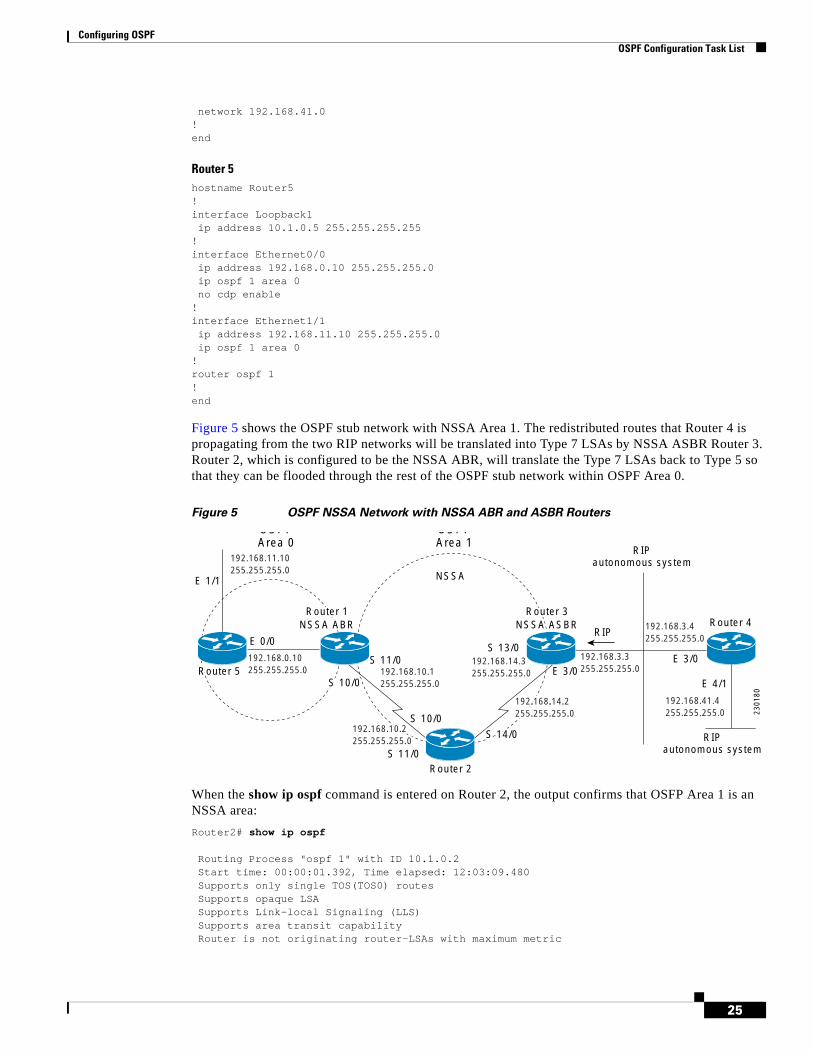
Configuring OSPF OSPF Configuration Task List
25
network 192.168.41.0!end
Router 5hostname Router5!interface Loopback1 ip address 10.1.0.5 255.255.255.255!interface Ethernet0/0 ip address 192.168.0.10 255.255.255.0 ip ospf 1 area 0 no cdp enable!interface Ethernet1/1 ip address 192.168.11.10 255.255.255.0 ip ospf 1 area 0!router ospf 1!end
Figure 5 shows the OSPF stub network with NSSA Area 1. The redistributed routes that Router 4 is propagating from the two RIP networks will be translated into Type 7 LSAs by NSSA ASBR Router 3. Router 2, which is configured to be the NSSA ABR, will translate the Type 7 LSAs back to Type 5 so that they can be flooded through the rest of the OSPF stub network within OSPF Area 0.
Figure 5 OSPF NSSA Network with NSSA ABR and ASBR Routers
When the show ip ospf command is entered on Router 2, the output confirms that OSFP Area 1 is an NSSA area:
Router2# show ip ospf
Routing Process "ospf 1" with ID 10.1.0.2 Start time: 00:00:01.392, Time elapsed: 12:03:09.480 Supports only single TOS(TOS0) routes Supports opaque LSA Supports Link-local Signaling (LLS) Supports area transit capability Router is not originating router-LSAs with maximum metric
E 3/0
E 4/1
Router 2
Router 4
E 3/0
RIP
RIPautonomous system
RIPautonomous system
S 13/0E 0/0
E 1/1 NSSA
S 11/0
S 10/0
OSPFArea 1
OSPFArea 0
2301
80
192.168.14.3255.255.255.0
192.168.3.3255.255.255.0192.168.10.1
255.255.255.0
192.168.3.4255.255.255.0
192.168.41.4255.255.255.0
192.168.11.10255.255.255.0
192.168.0.10255.255.255.0Router 5
Router 2NSSA ABR
Router 3NSSA ASBR
S 11/0
S 10/0Router 5
Router 1NSSA ABR
Router 3NSSA ASBR
S 11/0
S 10/0
S 14/0192.168.10.2255.255.255.0
192.168.14.2255.255.255.0
S 14/0192.168.10.2255.255.255.0
192.168.14.2255.255.255.0
Configuring OSPF OSPF Configuration Task List
26
Initial SPF schedule delay 5000 msecs Minimum hold time between two consecutive SPFs 10000 msecs Maximum wait time between two consecutive SPFs 10000 msecs Incremental-SPF disabled Minimum LSA interval 5 secs Minimum LSA arrival 1000 msecs LSA group pacing timer 240 secs Interface flood pacing timer 33 msecs Retransmission pacing timer 66 msecs Number of external LSA 0. Checksum Sum 0x000000 Number of opaque AS LSA 0. Checksum Sum 0x000000 Number of DCbitless external and opaque AS LSA 0 Number of DoNotAge external and opaque AS LSA 0 Number of areas in this router is 1. 0 normal 0 stub 1 nssa Number of areas transit capable is 0 External flood list length 0
Area 1Number of interfaces in this area is 2
! It is a NSSA areaArea has no authenticationSPF algorithm last executed 11:37:58.836 agoSPF algorithm executed 3 timesArea ranges areNumber of LSA 7. Checksum Sum 0x045598Number of opaque link LSA 0. Checksum Sum 0x000000Number of DCbitless LSA 0Number of indication LSA 0Number of DoNotAge LSA 0Flood list length 0
Router2# show ip ospf data
OSPF Router with ID (10.1.0.2) (Process ID 1)
Router Link States (Area 1)
Link ID ADV Router Age Seq# Checksum Link count10.1.0.1 10.1.0.1 1990 0x80000016 0x00CBCB 210.1.0.2 10.1.0.2 1753 0x80000016 0x009371 410.1.0.3 10.1.0.3 1903 0x80000016 0x004149 2
Summary Net Link States (Area 1)
Link ID ADV Router Age Seq# Checksum192.168.0.0 10.1.0.1 1990 0x80000017 0x00A605192.168.11.0 10.1.0.1 1990 0x80000015 0x009503
Type-7 AS External Link States (Area 1)
Link ID ADV Router Age Seq# Checksum Tag192.168.3.0 10.1.0.3 1903 0x80000015 0x00484F 0192.168.41.0 10.1.0.3 1903 0x80000015 0x00A4CC 0
Entering the show ip ospf database data command displays additional information about redistribution between Type 5 and Type 7 LSAs for routes that have been injected into the NSSA area and then flooded through the OSPF network.
Router2# show ip ospf database data
OSPF Router with ID (10.1.0.2) (Process ID 1)
Area 1 database summaryLSA Type Count Delete Maxage
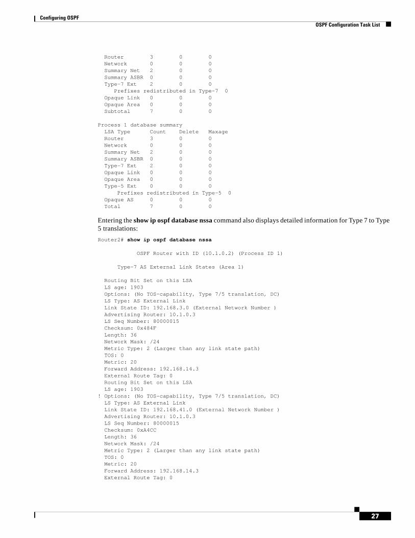
Configuring OSPF OSPF Configuration Task List
27
Router 3 0 0 Network 0 0 0 Summary Net 2 0 0 Summary ASBR 0 0 0 Type-7 Ext 2 0 0
Prefixes redistributed in Type-7 0Opaque Link 0 0 0 Opaque Area 0 0 0 Subtotal 7 0 0
Process 1 database summaryLSA Type Count Delete MaxageRouter 3 0 0 Network 0 0 0 Summary Net 2 0 0 Summary ASBR 0 0 0 Type-7 Ext 2 0 0 Opaque Link 0 0 0 Opaque Area 0 0 0 Type-5 Ext 0 0 0
Prefixes redistributed in Type-5 0Opaque AS 0 0 0 Total 7 0 0
Entering the show ip ospf database nssa command also displays detailed information for Type 7 to Type 5 translations:
Router2# show ip ospf database nssa
OSPF Router with ID (10.1.0.2) (Process ID 1)
Type-7 AS External Link States (Area 1)
Routing Bit Set on this LSALS age: 1903Options: (No TOS-capability, Type 7/5 translation, DC)LS Type: AS External LinkLink State ID: 192.168.3.0 (External Network Number )Advertising Router: 10.1.0.3LS Seq Number: 80000015Checksum: 0x484FLength: 36Network Mask: /24Metric Type: 2 (Larger than any link state path)TOS: 0 Metric: 20 Forward Address: 192.168.14.3External Route Tag: 0Routing Bit Set on this LSALS age: 1903
! Options: (No TOS-capability, Type 7/5 translation, DC)LS Type: AS External LinkLink State ID: 192.168.41.0 (External Network Number )Advertising Router: 10.1.0.3LS Seq Number: 80000015Checksum: 0xA4CCLength: 36Network Mask: /24Metric Type: 2 (Larger than any link state path)TOS: 0 Metric: 20 Forward Address: 192.168.14.3External Route Tag: 0
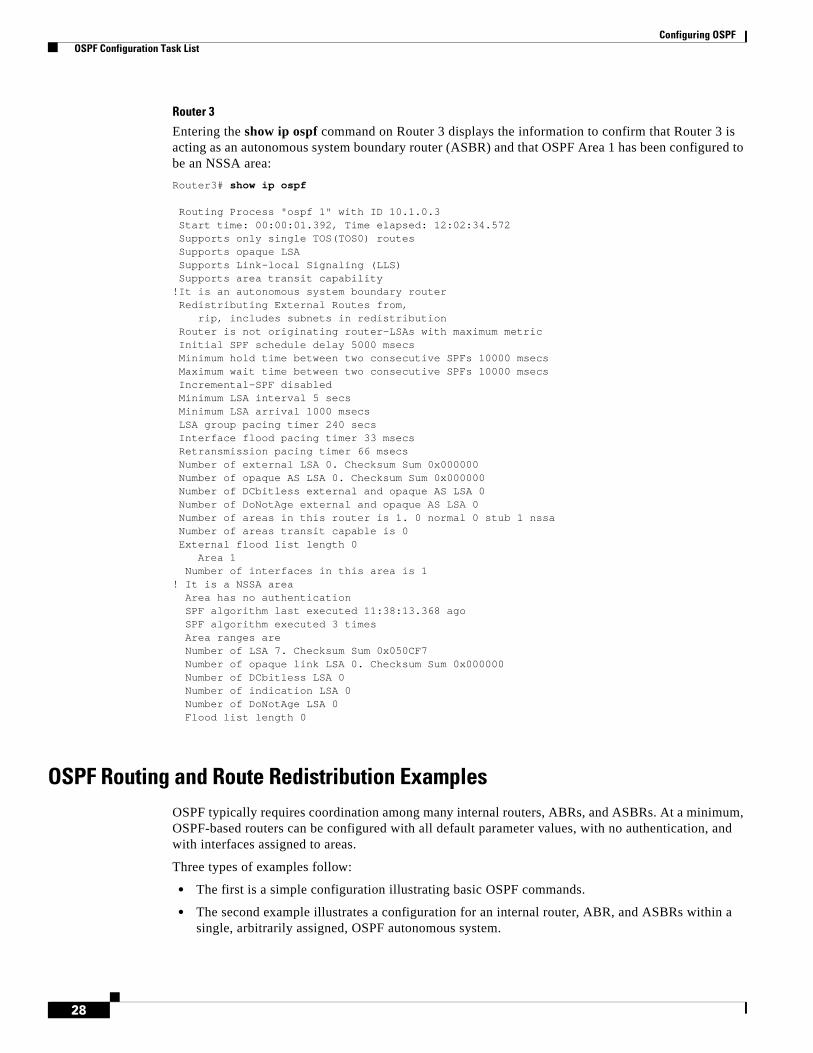
Configuring OSPF OSPF Configuration Task List
28
Router 3
Entering the show ip ospf command on Router 3 displays the information to confirm that Router 3 is acting as an autonomous system boundary router (ASBR) and that OSPF Area 1 has been configured to be an NSSA area:
Router3# show ip ospf
Routing Process "ospf 1" with ID 10.1.0.3 Start time: 00:00:01.392, Time elapsed: 12:02:34.572 Supports only single TOS(TOS0) routes Supports opaque LSA Supports Link-local Signaling (LLS) Supports area transit capability!It is an autonomous system boundary router Redistributing External Routes from, rip, includes subnets in redistribution Router is not originating router-LSAs with maximum metric Initial SPF schedule delay 5000 msecs Minimum hold time between two consecutive SPFs 10000 msecs Maximum wait time between two consecutive SPFs 10000 msecs Incremental-SPF disabled Minimum LSA interval 5 secs Minimum LSA arrival 1000 msecs LSA group pacing timer 240 secs Interface flood pacing timer 33 msecs Retransmission pacing timer 66 msecs Number of external LSA 0. Checksum Sum 0x000000 Number of opaque AS LSA 0. Checksum Sum 0x000000 Number of DCbitless external and opaque AS LSA 0 Number of DoNotAge external and opaque AS LSA 0 Number of areas in this router is 1. 0 normal 0 stub 1 nssa Number of areas transit capable is 0 External flood list length 0
Area 1Number of interfaces in this area is 1
! It is a NSSA areaArea has no authenticationSPF algorithm last executed 11:38:13.368 agoSPF algorithm executed 3 timesArea ranges areNumber of LSA 7. Checksum Sum 0x050CF7Number of opaque link LSA 0. Checksum Sum 0x000000Number of DCbitless LSA 0Number of indication LSA 0Number of DoNotAge LSA 0Flood list length 0
OSPF Routing and Route Redistribution ExamplesOSPF typically requires coordination among many internal routers, ABRs, and ASBRs. At a minimum, OSPF-based routers can be configured with all default parameter values, with no authentication, and with interfaces assigned to areas.
Three types of examples follow:
• The first is a simple configuration illustrating basic OSPF commands.
• The second example illustrates a configuration for an internal router, ABR, and ASBRs within a single, arbitrarily assigned, OSPF autonomous system.
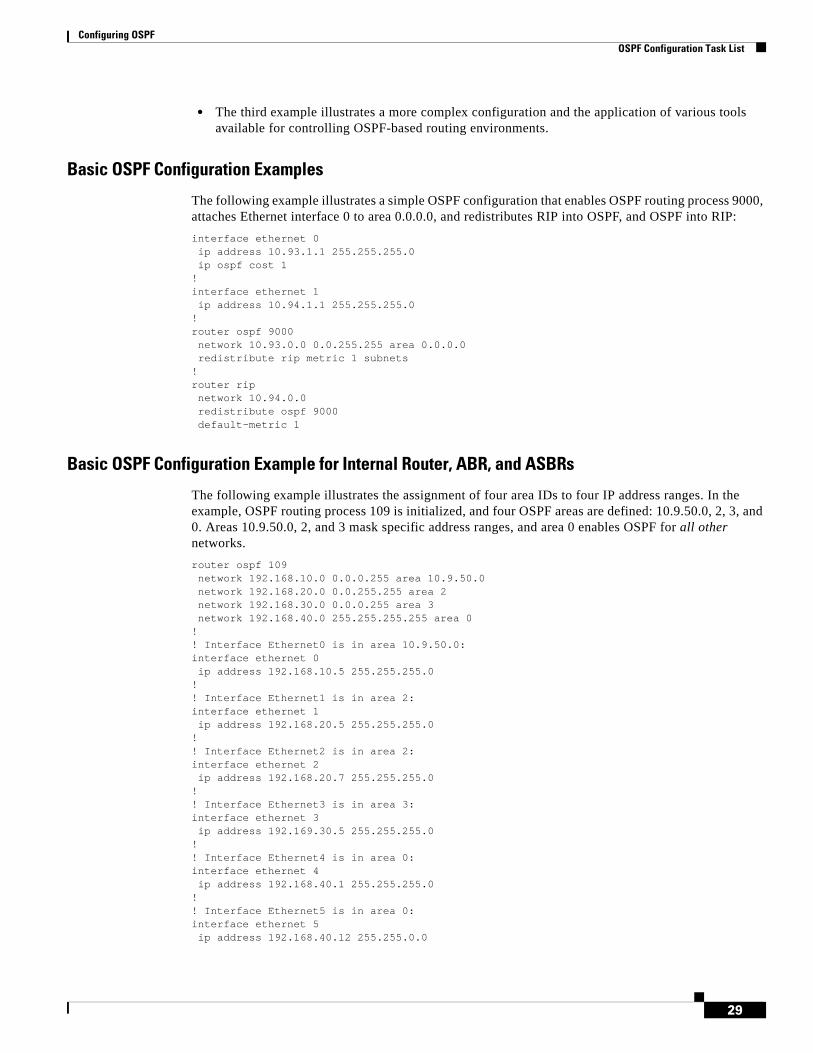
Configuring OSPF OSPF Configuration Task List
29
• The third example illustrates a more complex configuration and the application of various tools available for controlling OSPF-based routing environments.
Basic OSPF Configuration Examples
The following example illustrates a simple OSPF configuration that enables OSPF routing process 9000, attaches Ethernet interface 0 to area 0.0.0.0, and redistributes RIP into OSPF, and OSPF into RIP:
interface ethernet 0ip address 10.93.1.1 255.255.255.0ip ospf cost 1
!interface ethernet 1ip address 10.94.1.1 255.255.255.0
!router ospf 9000network 10.93.0.0 0.0.255.255 area 0.0.0.0redistribute rip metric 1 subnets
!router ripnetwork 10.94.0.0redistribute ospf 9000default-metric 1
Basic OSPF Configuration Example for Internal Router, ABR, and ASBRs
The following example illustrates the assignment of four area IDs to four IP address ranges. In the example, OSPF routing process 109 is initialized, and four OSPF areas are defined: 10.9.50.0, 2, 3, and 0. Areas 10.9.50.0, 2, and 3 mask specific address ranges, and area 0 enables OSPF for all other networks.
router ospf 109network 192.168.10.0 0.0.0.255 area 10.9.50.0network 192.168.20.0 0.0.255.255 area 2network 192.168.30.0 0.0.0.255 area 3network 192.168.40.0 255.255.255.255 area 0
!! Interface Ethernet0 is in area 10.9.50.0:interface ethernet 0ip address 192.168.10.5 255.255.255.0
!! Interface Ethernet1 is in area 2:interface ethernet 1ip address 192.168.20.5 255.255.255.0
!! Interface Ethernet2 is in area 2:interface ethernet 2ip address 192.168.20.7 255.255.255.0
!! Interface Ethernet3 is in area 3:interface ethernet 3ip address 192.169.30.5 255.255.255.0
!! Interface Ethernet4 is in area 0:interface ethernet 4ip address 192.168.40.1 255.255.255.0
!! Interface Ethernet5 is in area 0:interface ethernet 5ip address 192.168.40.12 255.255.0.0
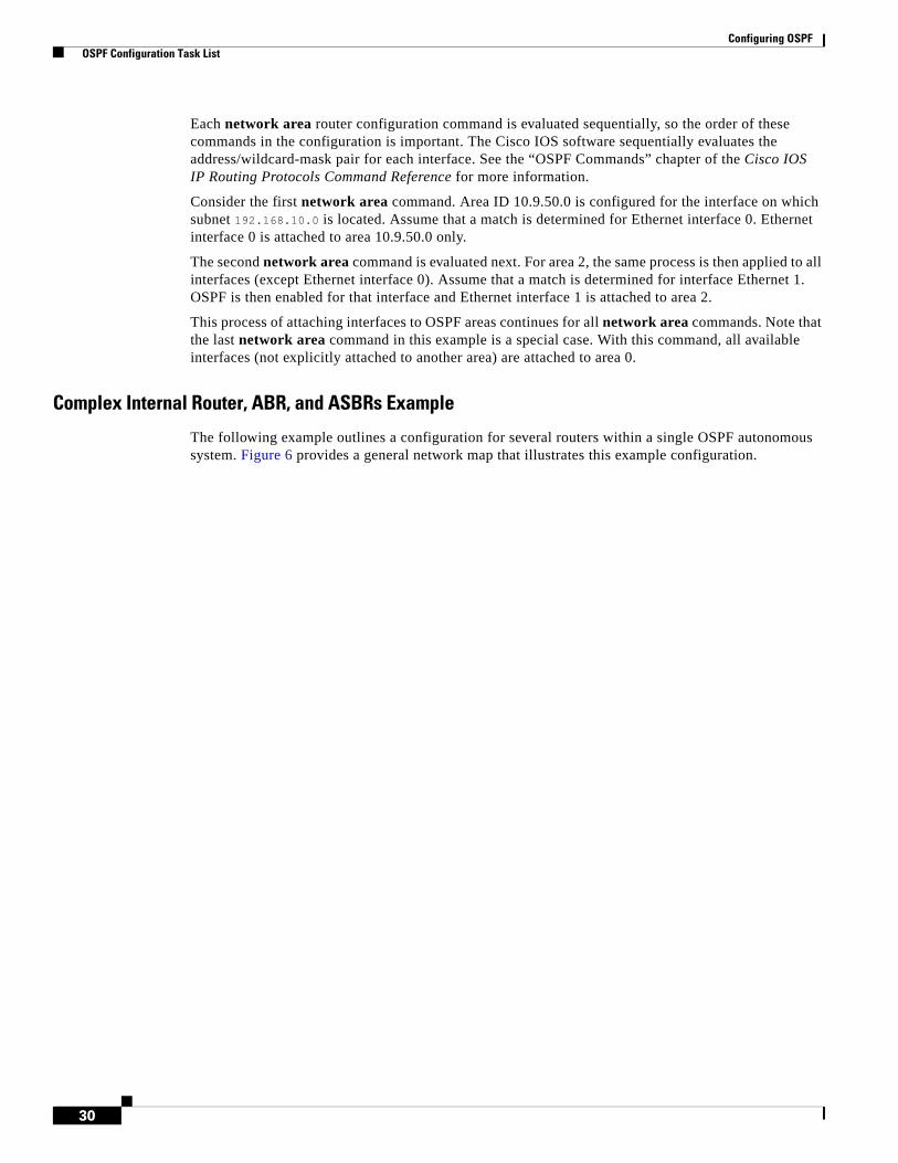
Configuring OSPF OSPF Configuration Task List
30
Each network area router configuration command is evaluated sequentially, so the order of these commands in the configuration is important. The Cisco IOS software sequentially evaluates the address/wildcard-mask pair for each interface. See the “OSPF Commands” chapter of the Cisco IOS IP Routing Protocols Command Reference for more information.
Consider the first network area command. Area ID 10.9.50.0 is configured for the interface on which subnet 192.168.10.0 is located. Assume that a match is determined for Ethernet interface 0. Ethernet interface 0 is attached to area 10.9.50.0 only.
The second network area command is evaluated next. For area 2, the same process is then applied to all interfaces (except Ethernet interface 0). Assume that a match is determined for interface Ethernet 1. OSPF is then enabled for that interface and Ethernet interface 1 is attached to area 2.
This process of attaching interfaces to OSPF areas continues for all network area commands. Note that the last network area command in this example is a special case. With this command, all available interfaces (not explicitly attached to another area) are attached to area 0.
Complex Internal Router, ABR, and ASBRs Example
The following example outlines a configuration for several routers within a single OSPF autonomous system. Figure 6 provides a general network map that illustrates this example configuration.
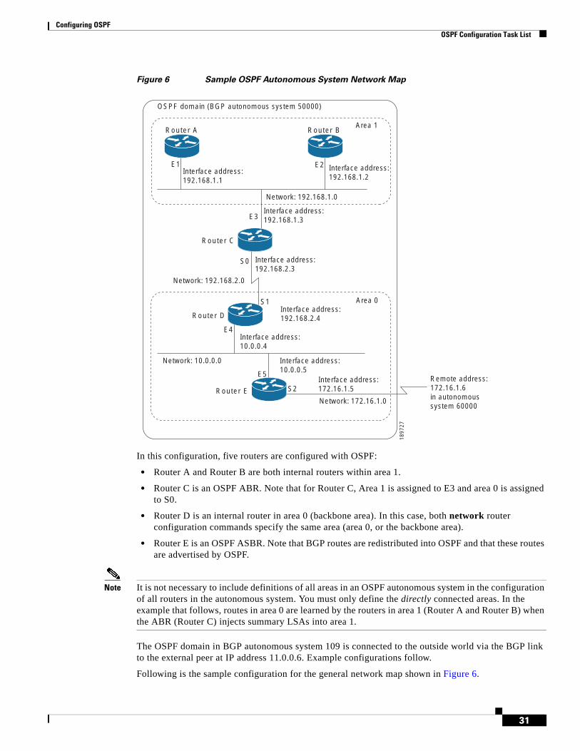
Configuring OSPF OSPF Configuration Task List
31
Figure 6 Sample OSPF Autonomous System Network Map
In this configuration, five routers are configured with OSPF:
• Router A and Router B are both internal routers within area 1.
• Router C is an OSPF ABR. Note that for Router C, Area 1 is assigned to E3 and area 0 is assigned to S0.
• Router D is an internal router in area 0 (backbone area). In this case, both network router configuration commands specify the same area (area 0, or the backbone area).
• Router E is an OSPF ASBR. Note that BGP routes are redistributed into OSPF and that these routes are advertised by OSPF.
Note It is not necessary to include definitions of all areas in an OSPF autonomous system in the configuration of all routers in the autonomous system. You must only define the directly connected areas. In the example that follows, routes in area 0 are learned by the routers in area 1 (Router A and Router B) when the ABR (Router C) injects summary LSAs into area 1.
The OSPF domain in BGP autonomous system 109 is connected to the outside world via the BGP link to the external peer at IP address 11.0.0.6. Example configurations follow.
Following is the sample configuration for the general network map shown in Figure 6.
E1 E2
E3
E5
S2
S1
E4
Interface address:192.168.1.1
Interface address:192.168.1.2
Interface address:192.168.1.3
Network: 192.168.1.0
Network: 192.168.2.0
Network: 10.0.0.0
Interface address:10.0.0.4
Interface address:172.16.1.5
Interface address:10.0.0.5
Network: 172.16.1.0
Remote address:172.16.1.6in autonomoussystem 60000
Area 1
Area 0
OSPF domain (BGP autonomous system 50000)
1897
27
Interface address:192.168.2.4
S0 Interface address:192.168.2.3
Router E
Router D
Router C
Router BRouter A
Configuring OSPF OSPF Configuration Task List
32
Router A Configuration—Internal Routerinterface ethernet 1ip address 192.168.1.1 255.255.255.0
router ospf 1network 192.168.0.0 0.0.255.255 area 1
Router B Configuration—Internal Routerinterface ethernet 2ip address 192.168.1.2 255.255.255.0
router ospf 202network 192.168.0.0 0.0.255.255 area 1
Router C Configuration—ABRinterface ethernet 3ip address 192.168.1.3 255.255.255.0
interface serial 0ip address 192.168.2.3 255.255.255.0
router ospf 999network 192.168.1.0 0.0.0.255 area 1network 192.168.2.0 0.0.0.255 area 0
Router D Configuration—Internal Routerinterface ethernet 4ip address 10.0.0.4 255.0.0.0
interface serial 1ip address 192.168.2.4 255.255.255.0
router ospf 50network 192.168.2.0 0.0.0.255 area 0network 10.0.0.0 0.255.255.255 area 0
Router E Configuration—ASBRinterface ethernet 5ip address 10.0.0.5 255.0.0.0
interface serial 2ip address 172.16.1.5 255.255.255.0
router ospf 65001network 10.0.0.0 0.255.255.255 area 0redistribute bgp 109 metric 1 metric-type 1
router bgp 109network 192.168.0.0network 10.0.0.0neighbor 172.16.1.6 remote-as 110

Configuring OSPF OSPF Configuration Task List
33
Complex OSPF Configuration for ABR Examples
The following example configuration accomplishes several tasks in setting up an ABR. These tasks can be split into two general categories:
• Basic OSPF configuration
• Route redistribution
The specific tasks outlined in this configuration are detailed briefly in the following descriptions. Figure 7 illustrates the network address ranges and area assignments for the interfaces.
Figure 7 Interface and Area Specifications for OSPF Example Configuration
The basic configuration tasks in this example are as follows:
• Configure address ranges for Ethernet interface 0 through Ethernet interface 3.
• Enable OSPF on each interface.
• Set up an OSPF authentication password for each area and network.
• Assign link-state metrics and other OSPF interface configuration options.
• Create a stub area with area ID 36.0.0.0. (Note that the authentication and stub options of the area router configuration command are specified with separate area command entries, but can be merged into a single area command.)
• Specify the backbone area (area 0).
Configuration tasks associated with redistribution are as follows:
• Redistribute IGRP and RIP into OSPF with various options set (including metric-type, metric, tag, and subnet).
• Redistribute IGRP and OSPF into RIP.
The following is an example OSPF configuration:
interface ethernet 0ip address 192.42.110.201 255.255.255.0ip ospf authentication-key abcdefghip ospf cost 10
!interface ethernet 1
Router A
1897
28
E3 E1
E2
E0
Network address range:192.168.110.0 through 192.168.110.255Area ID: 192.168.110.0
Network address range:10.56.0.0 through 10.56.255.255Area ID: 10.0.0.0Configured as stub area
Network address range:172.19.254.0 through 172.19.254.255Area ID: 0Configured as backbone area
Network address range:172.19.251.0 through 172.19.251.255Area ID: 0Configured as backbone area
Configuring OSPF OSPF Configuration Task List
34
ip address 172.19.251.202 255.255.255.0ip ospf authentication-key ijklmnopip ospf cost 20ip ospf retransmit-interval 10ip ospf transmit-delay 2ip ospf priority 4
!interface ethernet 2ip address 172.19.254.2 255.255.255.0ip ospf authentication-key abcdefghip ospf cost 10
!interface ethernet 3ip address 10.56.0.0 255.255.0.0ip ospf authentication-key ijklmnopip ospf cost 20ip ospf dead-interval 80
In the following configuration OSPF is on network 172.16.0.0:
router ospf 201network 10.10.0.0 0.255.255.255 area 10.10.0.0network 192.42.110.0 0.0.0.255 area 192.42.110.0network 172.16.0.0 0.0.255.255 area 0area 0 authenticationarea 10.10.0.0 stubarea 10.10.0.0 authenticationarea 10.10.0.0 default-cost 20area 192.42.110.0 authenticationarea 10.10.0.0 range 10.10.0.0 255.0.0.0area 192.42.110.0 range 192.42.110.0 255.255.255.0area 0 range 172.16.251.0 255.255.255.0area 0 range 172.16.254.0 255.255.255.0redistribute igrp 200 metric-type 2 metric 1 tag 200 subnetsredistribute rip metric-type 2 metric 1 tag 200
In the following configuration IGRP autonomous system 200 is on 131.119.0.0:
router igrp 200network 172.31.0.0
!! RIP for 192.168.110!router ripnetwork 192.168.110.0redistribute igrp 200 metric 1redistribute ospf 201 metric 1
Route Map ExamplesThe examples in this section illustrate the use of redistribution, with and without route maps. Examples from both the IP and Connectionless Network Service (CLNS) routing protocols are given.
The following example redistributes all OSPF routes into IGRP:
router igrp 109redistribute ospf 110
The following example redistributes RIP routes with a hop count equal to 1 into OSPF. These routes will be redistributed into OSPF as external LSAs with a metric of 5, a metric type of Type 1, and a tag equal to 1.
Configuring OSPF OSPF Configuration Task List
35
router ospf 109redistribute rip route-map rip-to-ospf
!route-map rip-to-ospf permitmatch metric 1set metric 5set metric-type type1set tag 1
The following example redistributes OSPF learned routes with tag 7 as a RIP metric of 15:
router ripredistribute ospf 109 route-map 5
!route-map 5 permitmatch tag 7set metric 15
The following example redistributes OSPF intra-area and interarea routes with next hop routers on serial interface 0 into BGP with an INTER_AS metric of 5:
router bgp 109redistribute ospf 109 route-map 10
!route-map 10 permitmatch route-type internalmatch interface serial 0set metric 5
The following example redistributes two types of routes into the integrated IS-IS routing table (supporting both IP and CLNS). The first type is OSPF external IP routes with tag 5; these routes are inserted into Level 2 IS-IS LSPs with a metric of 5. The second type is ISO-IGRP derived CLNS prefix routes that match CLNS access list 2000; these routes will be redistributed into IS-IS as Level 2 LSPs with a metric of 30.
router isisredistribute ospf 109 route-map 2redistribute iso-igrp nsfnet route-map 3
!route-map 2 permitmatch route-type externalmatch tag 5set metric 5set level level-2
!route-map 3 permitmatch address 2000set metric 30
With the following configuration, OSPF external routes with tags 1, 2, 3, and 5 are redistributed into RIP with metrics of 1, 1, 5, and 5, respectively. The OSPF routes with a tag of 4 are not redistributed.
router ripredistribute ospf 109 route-map 1
!route-map 1 permitmatch tag 1 2set metric 1
!route-map 1 permit match tag 3set metric 5
!route-map 1 deny
Configuring OSPF OSPF Configuration Task List
36
match tag 4!route map 1 permitmatch tag 5set metric 5
In the following configuration, a RIP learned route for network 160.89.0.0 and an ISO-IGRP learned route with prefix 49.0001.0002 will be redistributed into an IS-IS Level 2 LSP with a metric of 5:
router isisredistribute rip route-map 1redistribute iso-igrp remote route-map 1
!route-map 1 permitmatch ip address 1match clns address 2set metric 5set level level-2
!access-list 1 permit 192.168.0.0 0.0.255.255clns filter-set 2 permit 49.0001.0002...
The following configuration example illustrates how a route map is referenced by the default-information router configuration command. This type of reference is called conditional default origination. OSPF will originate the default route (network 0.0.0.0) with a Type 2 metric of 5 if 140.222.0.0 is in the routing table.
Note Only routes external to the OSPF process can be used for tracking, such as non-OSPF routes or OSPF routes from a separate OSPF process.
route-map ospf-default permitmatch ip address 1set metric 5set metric-type type-2
!access-list 1 permit 172.16.0.0 0.0.255.255
!router ospf 109default-information originate route-map ospf-default
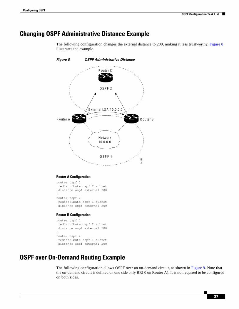
Configuring OSPF OSPF Configuration Task List
37
Changing OSPF Administrative Distance ExampleThe following configuration changes the external distance to 200, making it less trustworthy. Figure 8 illustrates the example.
Figure 8 OSPF Administrative Distance
Router A Configurationrouter ospf 1redistribute ospf 2 subnetdistance ospf external 200
!router ospf 2redistribute ospf 1 subnetdistance ospf external 200
Router B Configurationrouter ospf 1redistribute ospf 2 subnetdistance ospf external 200
!router ospf 2redistribute ospf 1 subnetdistance ospf external 200
OSPF over On-Demand Routing ExampleThe following configuration allows OSPF over an on-demand circuit, as shown in Figure 9. Note that the on-demand circuit is defined on one side only BRI 0 on Router A). It is not required to be configured on both sides.
Network10.0.0.0
OSPF 1
1483
0
OSPF 2
External LSA 10.0.0.0
Router A Router B
Router C
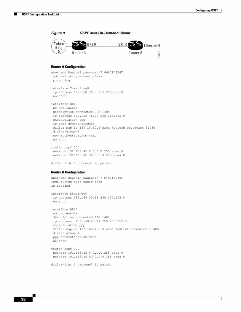
Configuring OSPF OSPF Configuration Task List
38
Figure 9 OSPF over On-Demand Circuit
Router A Configurationusername RouterB password 7 060C1A2F47isdn switch-type basic-5essip routing!interface TokenRing0ip address 192.168.50.5 255.255.255.0no shut
!interface BRI0no cdp enabledescription connected PBX 1485ip address 192.168.45.30 255.255.255.0encapsulation pppip ospf demand-circuitdialer map ip 140.10.10.6 name RouterB broadcast 61484dialer-group 1ppp authentication chapno shut
!router ospf 100network 192.168.45.0 0.0.0.255 area 0network 192.168.45.50 0.0.0.255 area 0
!dialer-list 1 protocol ip permit
Router B Configurationusername RouterA password 7 04511E0804isdn switch-type basic-5essip routing!interface Ethernet0ip address 192.168.50.16 255.255.255.0no shut
!interface BRI0no cdp enabledescription connected PBX 1484ip address 192.168.45.17 255.255.255.0encapsulation pppdialer map ip 192.168.45.19 name RouterA broadcast 61485dialer-group 1ppp authentication chapno shut
!router ospf 100network 192.168.45.0 0.0.0.255 area 0network 192.168.45.50 0.0.0.255 area 0
!dialer-list 1 protocol ip permit
TokenRing
0
BRI 0 BRI 0 Ethernet 0
Router A Router B
1487
3

Configuring OSPF OSPF Configuration Task List
39
LSA Group Pacing ExampleThe following example changes the OSPF pacing between LSA groups to 60 seconds:
router ospftimers pacing lsa-group 60
Block LSA Flooding ExampleThe following example prevents flooding of OSPF LSAs to broadcast, nonbroadcast, or point-to-point networks reachable through Ethernet interface 0:
interface ethernet 0ip ospf database-filter all out
The following example prevents flooding of OSPF LSAs to point-to-multipoint networks to the neighbor at IP address 1.2.3.4:
router ospf 109neighbor 10.10.10.45 database-filter all out
Ignore MOSPF LSA Packets ExampleThe following example configures the router to suppress the sending of syslog messages when it receives MOSPF packets:
router ospf 109ignore lsa mospf
CCDE, CCENT, CCSI, Cisco Eos, Cisco HealthPresence, Cisco IronPort, the Cisco logo, Cisco Lumin, Cisco Nexus, Cisco Nurse Connect, Cisco Pulse, Cisco StackPower, Cisco StadiumVision, Cisco TelePresence, Cisco Unified Computing System, Cisco WebEx, DCE, Flip Channels, Flip for Good, Flip Mino, Flipshare (Design), Flip Ultra, Flip Video, Flip Video (Design), Instant Broadband, and Welcome to the Human Network are trademarks; Changing the Way We Work, Live, Play, and Learn, Cisco Capital, Cisco Capital (Design), Cisco:Financed (Stylized), Cisco Store, and Flip Gift Card are service marks; and Access Registrar, Aironet, AllTouch, AsyncOS, Bringing the Meeting To You, Catalyst, CCDA, CCDP, CCIE, CCIP, CCNA, CCNP, CCSP, CCVP, Cisco, the Cisco Certified Internetwork Expert logo, Cisco IOS, Cisco Press, Cisco Systems, Cisco Systems Capital, the Cisco Systems logo, Cisco Unity, Collaboration Without Limitation, Continuum, EtherFast, EtherSwitch, Event Center, Explorer, Fast Step, Follow Me Browsing, FormShare, GainMaker, GigaDrive, HomeLink, iLYNX, Internet Quotient, IOS, iPhone, iQuick Study, IronPort, the IronPort logo, Laser Link, LightStream, Linksys, MediaTone, MeetingPlace, MeetingPlace Chime Sound, MGX, Networkers, Networking Academy, Network Registrar, PCNow, PIX, PowerKEY, PowerPanels, PowerTV, PowerTV (Design), PowerVu, Prisma, ProConnect, ROSA, ScriptShare, SenderBase, SMARTnet, Spectrum Expert, StackWise, The Fastest Way to Increase Your Internet Quotient, TransPath, WebEx, and the WebEx logo are registered trademarks of Cisco Systems, Inc. and/or its affiliates in the United States and certain other countries.
All other trademarks mentioned in this document or website are the property of their respective owners. The use of the word partner does not imply a partnership relationship between Cisco and any other company. (0908R)
Any Internet Protocol (IP) addresses used in this document are not intended to be actual addresses. Any examples, command display output, and figures included in the document are shown for illustrative purposes only. Any use of actual IP addresses in illustrative content is unintentional and coincidental.
© 2008 Cisco Systems, Inc. All rights reserved.

Configuring OSPF OSPF Configuration Task List
40
Americas Headquarters:Cisco Systems, Inc., 170 West Tasman Drive, San Jose, CA 95134-1706 USA
OSPF ABR Type 3 LSA Filtering
First Published: 12.0(15)SLast Updated: July 2009
The OSPF ABR Type 3 LSA Filtering feature extends the ability of an ABR that is running the OSPF protocol to filter type 3 link-state advertisements (LSAs) that are sent between different OSPF areas. This feature allows only packets with specified prefixes to be sent from one area to another area and restricts all packets with other prefixes. This type of area filtering can be applied out of a specific OSPF area, into a specific OSPF area, or into and out of the same OSPF areas at the same time.
History for the OSPF ABR Type 3 LSA Filtering Feature
Finding Support Information for Platforms and Cisco IOS Software Images
Use Cisco Feature Navigator to find information about platform support and Cisco IOS software image support. Access Cisco Feature Navigator at http://www.cisco.com/go/fn. You must have an account on Cisco.com. If you do not have an account or have forgotten your username or password, click Cancel at the login dialog box and follow the instructions that appear.
Release Modification
12.0(15)S This feature was introduced.
12.2(4)T This feature was integrated into Cisco IOS Release 12.2(4)T.
12.2(4)T3 Support for the Cisco 7500 series was added in Cisco IOS Release 12.2(4)T3.
12.2(8)T Support for the Cisco 1710, 1721, 3631, 3725, 3745 and IGX 8400 series URM was added in Cisco IOS Release 12.2(8)T.
12.2(11)T Support for the Cisco AS5300, AS5400, and AS5800 series was integrated into Cisco IOS Release 12.2(11)T.
12.2(28)SB This feature was integrated into Cisco IOS Release 12.2(28)SB.
OSPF ABR Type 3 LSA Filtering Contents
2
Contents• Benefits
• Restrictions
• Configuration Tasks, page 2
• Configuration Examples, page 4
• Additional References, page 4
• Command Reference, page 6
BenefitsThe OSPF ABR Type 3 LSA Filtering feature gives the administrator improved control of route distribution between OSPF areas.
RestrictionsOnly type 3 LSAs that originate from an ABR are filtered.
Related Features and Technologies This feature is an extension of the OSPF routing protocol. For more information about configuring OSPF and configuring route summarization and filtering, refer to the “OSPF” chapter of the Cisco IOS IP Configuration Guide, Release 12.4 and the Cisco IOS IP Routing Protocols Command Reference, Release 12.4T.
Configuration TasksSee the following sections for configuration tasks for the OSPF ABR Type 3 LSA Filtering feature. Each task in the list is identified as either required or optional:
• Configuring OSPF ABR Type 3 LSA Filtering, page 3 (required)
• Verifying OSPF ABR Type 3 LSA Filtering, page 3 (optional)
• Monitoring and Maintaining OSPF ABR Type 3 LSA Filtering, page 4
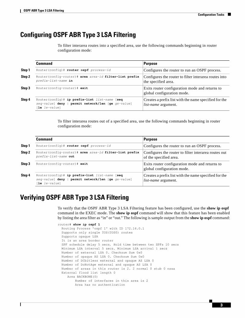
OSPF ABR Type 3 LSA Filtering Configuration Tasks
3
Configuring OSPF ABR Type 3 LSA FilteringTo filter interarea routes into a specified area, use the following commands beginning in router configuration mode:
To filter interarea routes out of a specified area, use the following commands beginning in router configuration mode:
Verifying OSPF ABR Type 3 LSA FilteringTo verify that the OSPF ABR Type 3 LSA Filtering feature has been configured, use the show ip ospf command in the EXEC mode. The show ip ospf command will show that this feature has been enabled by listing the area filter as “in” or “out.” The following is sample output from the show ip ospf command:
router# show ip ospf 1 Routing Process "ospf 1" with ID 172.16.0.1 Supports only single TOS(TOS0) routes Supports opaque LSA It is an area border router SPF schedule delay 5 secs, Hold time between two SPFs 10 secs Minimum LSA interval 5 secs. Minimum LSA arrival 1 secs Number of external LSA 0. Checksum Sum 0x0 Number of opaque AS LSA 0. Checksum Sum 0x0 Number of DCbitless external and opaque AS LSA 0 Number of DoNotAge external and opaque AS LSA 0 Number of areas in this router is 2. 2 normal 0 stub 0 nssa External flood list length 0 Area BACKBONE(0) Number of interfaces in this area is 2 Area has no authentication
Command Purpose
Step 1 Router(config)# router ospf process-id Configures the router to run an OSPF process.
Step 2 Router(config-router)# area area-id filter-list prefix prefix-list-name in
Configures the router to filter interarea routes into the specified area.
Step 3 Router(config-router)# exit Exits router configuration mode and returns to global configuration mode.
Step 4 Router(config)# ip prefix-list list-name [seq seq-value] deny | permit network/len [ge ge-value] [le le-value]
Creates a prefix list with the name specified for the list-name argument.
Command Purpose
Step 1 Router(config)# router ospf process-id Configures the router to run an OSPF process.
Step 2 Router(config-router)# area area-id filter-list prefix prefix-list-name out
Configures the router to filter interarea routes out of the specified area.
Step 3 Router(config-router)# exit Exits router configuration mode and returns to global configuration mode.
Step 4 Router(config)# ip prefix-list list-name [seq seq-value] deny | permit network/len [ge ge-value][le le-value]
Creates a prefix list with the name specified for the list-name argument.
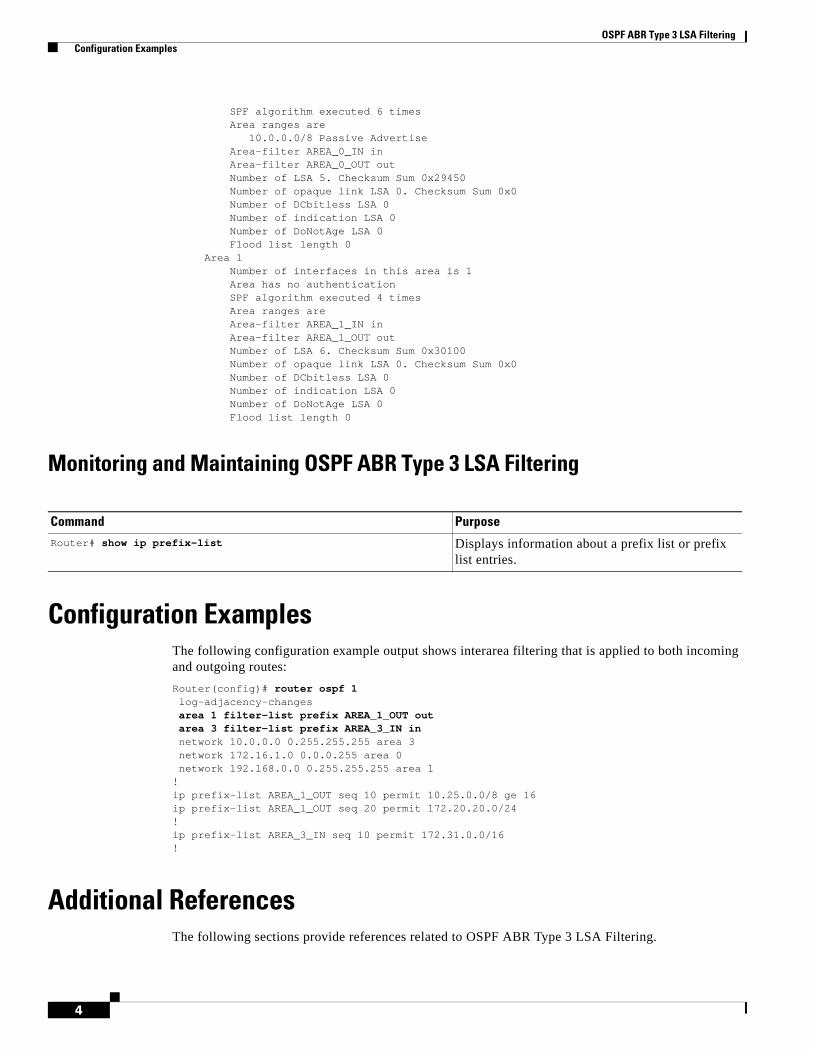
OSPF ABR Type 3 LSA Filtering Configuration Examples
4
SPF algorithm executed 6 times Area ranges are 10.0.0.0/8 Passive Advertise Area-filter AREA_0_IN in Area-filter AREA_0_OUT out Number of LSA 5. Checksum Sum 0x29450 Number of opaque link LSA 0. Checksum Sum 0x0 Number of DCbitless LSA 0 Number of indication LSA 0 Number of DoNotAge LSA 0 Flood list length 0 Area 1 Number of interfaces in this area is 1 Area has no authentication SPF algorithm executed 4 times Area ranges are Area-filter AREA_1_IN in Area-filter AREA_1_OUT out Number of LSA 6. Checksum Sum 0x30100 Number of opaque link LSA 0. Checksum Sum 0x0 Number of DCbitless LSA 0 Number of indication LSA 0 Number of DoNotAge LSA 0 Flood list length 0
Monitoring and Maintaining OSPF ABR Type 3 LSA Filtering
Configuration ExamplesThe following configuration example output shows interarea filtering that is applied to both incoming and outgoing routes:
Router(config)# router ospf 1 log-adjacency-changes area 1 filter-list prefix AREA_1_OUT out area 3 filter-list prefix AREA_3_IN in network 10.0.0.0 0.255.255.255 area 3 network 172.16.1.0 0.0.0.255 area 0 network 192.168.0.0 0.255.255.255 area 1!ip prefix-list AREA_1_OUT seq 10 permit 10.25.0.0/8 ge 16ip prefix-list AREA_1_OUT seq 20 permit 172.20.20.0/24!ip prefix-list AREA_3_IN seq 10 permit 172.31.0.0/16!
Additional ReferencesThe following sections provide references related to OSPF ABR Type 3 LSA Filtering.
Command PurposeRouter# show ip prefix-list Displays information about a prefix list or prefix
list entries.
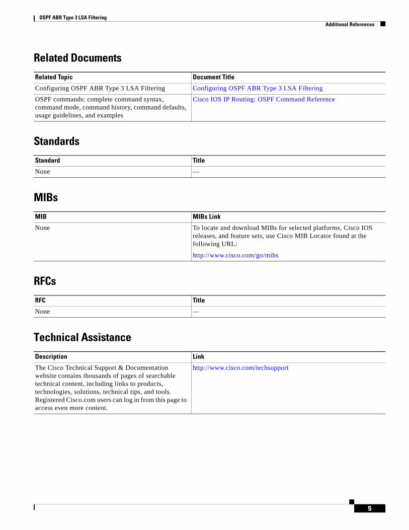
OSPF ABR Type 3 LSA Filtering Additional References
5
Related Documents
Standards
MIBs
RFCs
Technical Assistance
Related Topic Document Title
Configuring OSPF ABR Type 3 LSA Filtering Configuring OSPF ABR Type 3 LSA Filtering
OSPF commands: complete command syntax, command mode, command history, command defaults, usage guidelines, and examples
Cisco IOS IP Routing: OSPF Command Reference
Standard Title
None —
MIB MIBs Link
None To locate and download MIBs for selected platforms, Cisco IOS releases, and feature sets, use Cisco MIB Locator found at the following URL:
http://www.cisco.com/go/mibs
RFC Title
None —
Description Link
The Cisco Technical Support & Documentation website contains thousands of pages of searchable technical content, including links to products, technologies, solutions, technical tips, and tools. Registered Cisco.com users can log in from this page to access even more content.
http://www.cisco.com/techsupport

OSPF ABR Type 3 LSA Filtering Command Reference
6
Command ReferenceThe following commands are introduced or modified in the feature or features documented in this module. For information about these commands, see the Cisco IOS IP Routing: OSPF Command Reference
CCDE, CCENT, CCSI, Cisco Eos, Cisco HealthPresence, Cisco IronPort, the Cisco logo, Cisco Nurse Connect, Cisco Pulse, Cisco SensorBase, Cisco StackPower, Cisco StadiumVision, Cisco TelePresence, Cisco Unified Computing System, Cisco WebEx, DCE, Flip Channels, Flip for Good, Flip Mino, Flipshare (Design), Flip Ultra, Flip Video, Flip Video (Design), Instant Broadband, and Welcome to the Human Network are trademarks; Changing the Way We Work, Live, Play, and Learn, Cisco Capital, Cisco Capital (Design), Cisco:Financed (Stylized), Cisco Store, Flip Gift Card, and One Million Acts of Green are service marks; and Access Registrar, Aironet, AllTouch, AsyncOS, Bringing the Meeting To You, Catalyst, CCDA, CCDP, CCIE, CCIP, CCNA, CCNP, CCSP, CCVP, Cisco, the Cisco Certified Internetwork Expert logo, Cisco IOS, Cisco Lumin, Cisco Nexus, Cisco Press, Cisco Systems, Cisco Systems Capital, the Cisco Systems logo, Cisco Unity, Collaboration Without Limitation, Continuum, EtherFast, EtherSwitch, Event Center, Explorer, Follow Me Browsing, GainMaker, iLYNX, IOS, iPhone, IronPort, the IronPort logo, Laser Link, LightStream, Linksys, MeetingPlace, MeetingPlace Chime Sound, MGX, Networkers, Networking Academy, PCNow, PIX, PowerKEY, PowerPanels, PowerTV, PowerTV (Design), PowerVu, Prisma, ProConnect, ROSA, SenderBase, SMARTnet, Spectrum Expert, StackWise, WebEx, and the WebEx logo are registered trademarks of Cisco Systems, Inc. and/or its affiliates in the United States and certain other countries.
All other trademarks mentioned in this document or website are the property of their respective owners. The use of the word partner does not imply a partnership relationship between Cisco and any other company. (0910R)
Any Internet Protocol (IP) addresses used in this document are not intended to be actual addresses. Any examples, command display output, and figures included in the document are shown for illustrative purposes only. Any use of actual IP addresses in illustrative content is unintentional and coincidental.
© 2006–2008 Cisco Systems, Inc. All rights reserved.
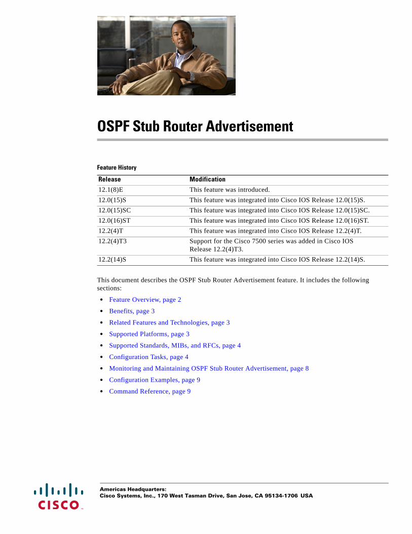
Americas Headquarters:Cisco Systems, Inc., 170 West Tasman Drive, San Jose, CA 95134-1706 USA
OSPF Stub Router Advertisement
Feature History
This document describes the OSPF Stub Router Advertisement feature. It includes the following sections:
• Feature Overview, page 2
• Benefits, page 3
• Related Features and Technologies, page 3
• Supported Platforms, page 3
• Supported Standards, MIBs, and RFCs, page 4
• Configuration Tasks, page 4
• Monitoring and Maintaining OSPF Stub Router Advertisement, page 8
• Configuration Examples, page 9
• Command Reference, page 9
Release Modification
12.1(8)E This feature was introduced.
12.0(15)S This feature was integrated into Cisco IOS Release 12.0(15)S.
12.0(15)SC This feature was integrated into Cisco IOS Release 12.0(15)SC.
12.0(16)ST This feature was integrated into Cisco IOS Release 12.0(16)ST.
12.2(4)T This feature was integrated into Cisco IOS Release 12.2(4)T.
12.2(4)T3 Support for the Cisco 7500 series was added in Cisco IOS Release 12.2(4)T3.
12.2(14)S This feature was integrated into Cisco IOS Release 12.2(14)S.
OSPF Stub Router Advertisement Feature Overview
2
Feature OverviewThe OSPF Stub Router Advertisement feature allows you to bring a new router into a network without immediately routing traffic through the new router and allows you to gracefully shut down or reload a router without dropping packets that are destined for other networks. This feature introduces three configuration options that allow you to configure a router that is running the Open Shortest Path First (OSPF) protocol to advertise a maximum or infinite metric to all neighbors.
When any of these three configuration options are enabled on a router, the router will originate link-state advertisements (LSAs) with a maximum metric (LSInfinity: 0xFFFF) through all nonstub links. The advertisement of a maximum metric causes other routers to assign a cost to the new router that is higher than the cost of using an alternate path. Because of the high cost assigned to paths that pass through the new router, other routers will not use a path through the new router as a transit path to forward traffic that is destined for other networks, which allows switching and routing functions to be up and running and routing tables to converge before transit traffic is routed through this router.
Note Directly connected links in a stub network are not affected by the configuration of a maximum or infinite metric because the cost of a stub link is always set to the output interface cost.
Allowing Routing Tables to ConvergeTwo configuration options introduced by the OSPF Stub Router Advertisement feature allow you to bring a new router into a network without immediately routing traffic through the new router. These configuration options are useful because Interior Gateway Protocols (IGPs) converge very quickly upon a router during startup or after a reload, often before Border Gateway Protocol (BGP) routing tables have completely converged. If neighbor routers forward traffic through a router while that router is building BGP routing tables, packets that have been received for other destinations may be dropped. Advertising a maximum metric during startup will allow routing tables to converge before traffic that is destined for other networks is sent through the router. The following two configuration options enable a router to advertise a maximum metric at startup:
• You can configure a timer to advertise a maximum metric when the router is started or reloaded. When this option is configured, the router will advertise a maximum metric, which forces neighbor routers to select alternate paths until the timer expires. When the timer expires, the router will advertise accurate (normal) metrics, and other routers will send traffic to this router depending on the cost. The configurable range of the timer is from 5 to 86,400 seconds.
• You can configure a router to advertise a maximum metric at startup until BGP routing tables converge or until the default timer expires (600 seconds). Once BGP routing tables converge or the default timer expires, the router will advertise accurate (normal) metrics and other routers will send traffic to this router, depending on the cost.
Configuring a Graceful ShutdownThe third configuration option introduced by the OSPF Stub Router Advertisement feature allows you to gracefully remove a router from the network by advertising a maximum metric through all links, which allows other routers to select alternate paths for transit traffic to follow before the router is shut down. There are many situations where you may need to remove a router from the network. If a router is removed from a network and neighbor routers cannot detect that the physical interface is down,
OSPF Stub Router Advertisement Supported Platforms
3
neighbors will need to wait for dead timers to expire before the neighbors will remove the adjacency and routing tables will reconverge. This situation may occur when there is a switch between other routers and the router that is shut down. Packets may be dropped while the neighbor routing tables reconverge.
When this third option is configured, the router advertises a maximum metric, which allows neighbor routers to select alternate paths before the router is shut down. This configuration option could also be used to remove a router that is in a critical condition from the network without affecting traffic that is destined for other networks.
Note You should not save the running configuration of a router when it is configured for a graceful shutdown because the router will continue to advertise a maximum metric after it is reloaded.
Benefits
Improved Stability and Availability
Advertising a maximum metric through all links at startup or during a reload will prevent neighbor routers from using a path through the router as a transit path, thereby reducing the number of packets that are dropped and improving the stability and availability of the network.
Graceful Removal from the Network
Advertising a maximum metric before shutdown allows other routers to select alternate paths before the transit path through a router becomes inaccessible.
Related Features and TechnologiesThe OSPF Stub Router Advertisement feature is an extension of the OSPF routing protocol. For more information about configuring OSPF and BGP, refer to the Cisco IOS IP Routing Configuration Guide and the Cisco IOS IP Routing Command Reference.
Supported PlatformsThe OSPF Stub Router Advertisement feature is supported by the following platforms in Cisco IOS Release 12.2(14)S that support OSPF:
• Cisco 7200 series
• Cisco 7400 series
• Cisco 7500 series
Determining Platform Support Through Cisco Feature Navigator
Cisco IOS software is packaged in feature sets that support specific platforms. To get updated information regarding platform support for this feature, access Cisco Feature Navigator. Cisco Feature Navigator dynamically updates the list of supported platforms as new platform support is added for the feature.
OSPF Stub Router Advertisement Supported Standards, MIBs, and RFCs
4
Cisco Feature Navigator is a web-based tool that enables you to determine which Cisco IOS software images support a specific set of features and which features are supported in a specific Cisco IOS image. You can search by feature or release. Under the release section, you can compare releases side by side to display both the features unique to each software release and the features in common.
Cisco Feature Navigator is updated regularly when major Cisco IOS software releases and technology releases occur. For the most current information, go to the Cisco Feature Navigator home page at the following URL:
http://www.cisco.com/go/fn
Availability of Cisco IOS Software Images
Platform support for particular Cisco IOS software releases is dependent on the availability of the software images for those platforms. Software images for some platforms may be deferred, delayed, or changed without prior notice. For updated information about platform support and availability of software images for each Cisco IOS software release, refer to the online release notes or, if supported, Cisco Feature Navigator.
Supported Standards, MIBs, and RFCsStandards
No new or modified standards are supported by this feature.
MIBs
No new or modified MIBs are supported by this feature.
To obtain lists of supported MIBs by platform and Cisco IOS release, and to download MIB modules, go to the Cisco MIB website on Cisco.com at the following URL:
http://www.cisco.com/public/sw-center/netmgmt/cmtk/mibs.shtml
RFCs
• RFC 3137 OSPF Stub Router Advertisement
Configuration TasksSee the following sections for configuration tasks to configure OSPF to advertise a maximum metric. This feature has three different configuration options. All tasks are optional and should be individually configured.
• Configuring Advertisement on Startup (optional)
• Configuring Advertisement Until Routing Tables Converge (optional)
• Configuring Advertisement for a Graceful Shutdown (optional)
• Verifying the Advertisement of a Maximum Metric (optional)
Configuring Advertisement on StartupTo configure a router that is running OSPF to advertise a maximum metric during startup, use the following commands beginning in global configuration mode:
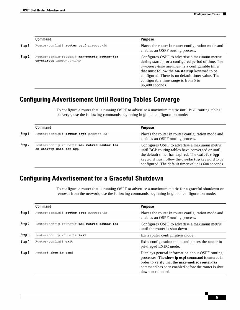
OSPF Stub Router Advertisement Configuration Tasks
5
Configuring Advertisement Until Routing Tables ConvergeTo configure a router that is running OSPF to advertise a maximum metric until BGP routing tables converge, use the following commands beginning in global configuration mode:
Configuring Advertisement for a Graceful ShutdownTo configure a router that is running OSPF to advertise a maximum metric for a graceful shutdown or removal from the network, use the following commands beginning in global configuration mode:
Command Purpose
Step 1 Router(config)# router ospf process-id Places the router in router configuration mode and enables an OSPF routing process.
Step 2 Router(config-router)# max-metric router-lsa on-startup announce-time
Configures OSPF to advertise a maximum metric during startup for a configured period of time. The announce-time argument is a configurable timer that must follow the on-startup keyword to be configured. There is no default timer value. The configurable time range is from 5 to 86,400 seconds.
Command Purpose
Step 1 Router(config)# router ospf process-id Places the router in router configuration mode and enables an OSPF routing process.
Step 2 Router(config-router)# max-metric router-lsa on-startup wait-for-bgp
Configures OSPF to advertise a maximum metric until BGP routing tables have converged or until the default timer has expired. The wait-for-bgp keyword must follow the on-startup keyword to be configured. The default timer value is 600 seconds.
Command Purpose
Step 1 Router(config)# router ospf process-id Places the router in router configuration mode and enables an OSPF routing process.
Step 2 Router(config-router)# max-metric router-lsa Configures OSPF to advertise a maximum metric until the router is shut down.
Step 3 Router(config-router)# exit Exits router configuration mode.
Step 4 Router(config)# exit Exits configuration mode and places the router in privileged EXEC mode.
Step 5 Router# show ip ospf Displays general information about OSPF routing processes. The show ip ospf command is entered in order to verify that the max-metric router-lsa command has been enabled before the router is shut down or reloaded.

OSPF Stub Router Advertisement Configuration Tasks
6
Note You should not save the running configuration of a router when it is configured for a graceful shutdown because the router will continue to advertise a maximum metric after it is reloaded.
Verifying the Advertisement of a Maximum Metric To verify that the advertisement of a maximum metric has been configured correctly, use the show ip ospf or show ip ospf database command.
The output of the show ip ospf command will display the condition, state, and remaining time delay of the advertisement of a maximum metric, depending on which options were configured with the max-metric router-lsa command.
The following sample output is similar to the output that will be displayed when the on-startup keyword and announce-time argument are configured with the max-metric router-lsa command:
Router# show ip ospfRouting Process "ospf 1998" with ID 10.18.134.155 Supports only single TOS(TOS0) routes Supports opaque LSA It is an area border and autonomous system boundary router Redistributing External Routes from, static, includes subnets in redistribution
Originating router-LSAs with maximum metric, Time remaining: 00:01:18Condition: on startup for 300 seconds, State: active
SPF schedule delay 5 secs, Hold time between two SPFs 10 secs Minimum LSA interval 5 secs. Minimum LSA arrival 1 secs Number of external LSA 7. Checksum Sum 0x47261 Number of opaque AS LSA 0. Checksum Sum 0x0 Number of DCbitless external and opaque AS LSA 0 Number of DoNotAge external and opaque AS LSA 0 Number of areas in this router is 2. 1 normal 0 stub 1 nssa External flood list length 0 Area BACKBONE(0) Number of interfaces in this area is 1 Area has no authentication SPF algorithm executed 3 times Area ranges are Number of LSA 8. Checksum Sum 0x474AE Number of opaque link LSA 0. Checksum Sum 0x0
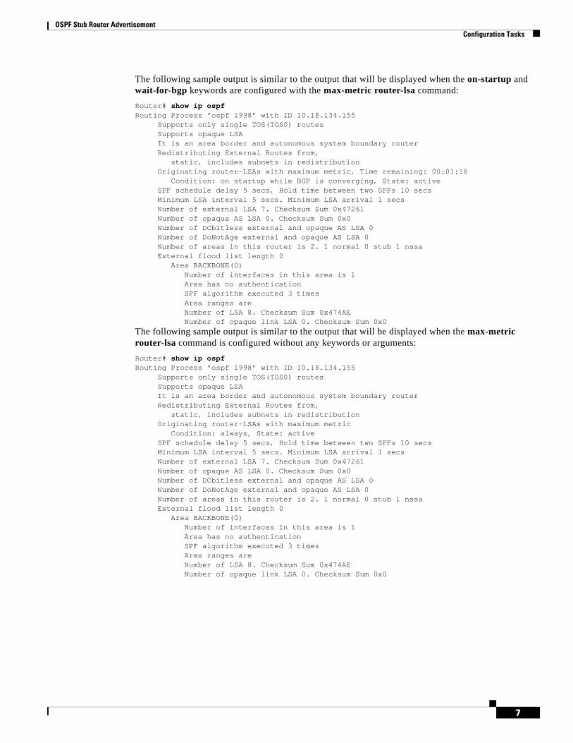
OSPF Stub Router Advertisement Configuration Tasks
7
The following sample output is similar to the output that will be displayed when the on-startup and wait-for-bgp keywords are configured with the max-metric router-lsa command:
Router# show ip ospfRouting Process "ospf 1998" with ID 10.18.134.155 Supports only single TOS(TOS0) routes Supports opaque LSA It is an area border and autonomous system boundary router Redistributing External Routes from, static, includes subnets in redistribution
Originating router-LSAs with maximum metric, Time remaining: 00:01:18Condition: on startup while BGP is converging, State: active
SPF schedule delay 5 secs, Hold time between two SPFs 10 secs Minimum LSA interval 5 secs. Minimum LSA arrival 1 secs Number of external LSA 7. Checksum Sum 0x47261 Number of opaque AS LSA 0. Checksum Sum 0x0 Number of DCbitless external and opaque AS LSA 0 Number of DoNotAge external and opaque AS LSA 0 Number of areas in this router is 2. 1 normal 0 stub 1 nssa External flood list length 0 Area BACKBONE(0) Number of interfaces in this area is 1 Area has no authentication SPF algorithm executed 3 times Area ranges are Number of LSA 8. Checksum Sum 0x474AE Number of opaque link LSA 0. Checksum Sum 0x0
The following sample output is similar to the output that will be displayed when the max-metric router-lsa command is configured without any keywords or arguments:
Router# show ip ospfRouting Process "ospf 1998" with ID 10.18.134.155 Supports only single TOS(TOS0) routes Supports opaque LSA It is an area border and autonomous system boundary router Redistributing External Routes from, static, includes subnets in redistribution
Originating router-LSAs with maximum metricCondition: always, State: active
SPF schedule delay 5 secs, Hold time between two SPFs 10 secs Minimum LSA interval 5 secs. Minimum LSA arrival 1 secs Number of external LSA 7. Checksum Sum 0x47261 Number of opaque AS LSA 0. Checksum Sum 0x0 Number of DCbitless external and opaque AS LSA 0 Number of DoNotAge external and opaque AS LSA 0 Number of areas in this router is 2. 1 normal 0 stub 1 nssa External flood list length 0 Area BACKBONE(0) Number of interfaces in this area is 1 Area has no authentication SPF algorithm executed 3 times Area ranges are Number of LSA 8. Checksum Sum 0x474AE Number of opaque link LSA 0. Checksum Sum 0x0
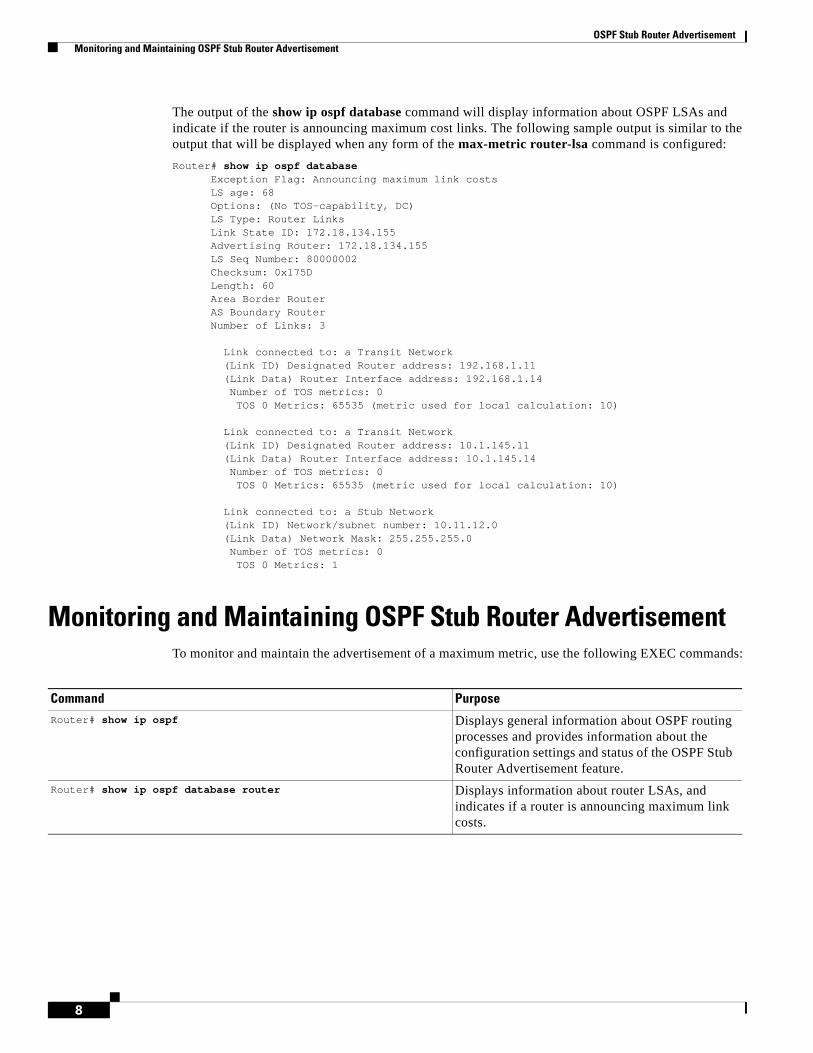
OSPF Stub Router Advertisement Monitoring and Maintaining OSPF Stub Router Advertisement
8
The output of the show ip ospf database command will display information about OSPF LSAs and indicate if the router is announcing maximum cost links. The following sample output is similar to the output that will be displayed when any form of the max-metric router-lsa command is configured:
Router# show ip ospf databaseException Flag: Announcing maximum link costs
LS age: 68 Options: (No TOS-capability, DC) LS Type: Router Links Link State ID: 172.18.134.155 Advertising Router: 172.18.134.155 LS Seq Number: 80000002 Checksum: 0x175D Length: 60 Area Border Router AS Boundary Router Number of Links: 3 Link connected to: a Transit Network (Link ID) Designated Router address: 192.168.1.11 (Link Data) Router Interface address: 192.168.1.14 Number of TOS metrics: 0 TOS 0 Metrics: 65535 (metric used for local calculation: 10) Link connected to: a Transit Network (Link ID) Designated Router address: 10.1.145.11 (Link Data) Router Interface address: 10.1.145.14 Number of TOS metrics: 0 TOS 0 Metrics: 65535 (metric used for local calculation: 10) Link connected to: a Stub Network (Link ID) Network/subnet number: 10.11.12.0 (Link Data) Network Mask: 255.255.255.0 Number of TOS metrics: 0 TOS 0 Metrics: 1
Monitoring and Maintaining OSPF Stub Router AdvertisementTo monitor and maintain the advertisement of a maximum metric, use the following EXEC commands:
Command PurposeRouter# show ip ospf Displays general information about OSPF routing
processes and provides information about the configuration settings and status of the OSPF Stub Router Advertisement feature.
Router# show ip ospf database router Displays information about router LSAs, and indicates if a router is announcing maximum link costs.
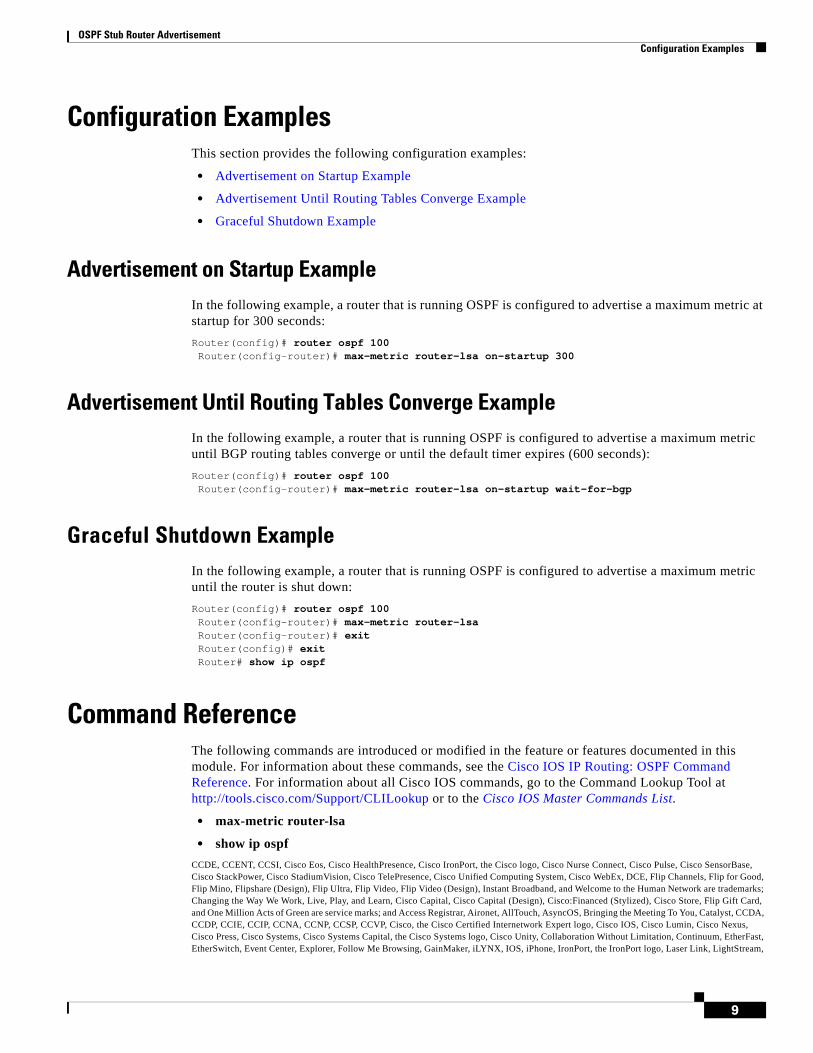
OSPF Stub Router Advertisement Configuration Examples
9
Configuration ExamplesThis section provides the following configuration examples:
• Advertisement on Startup Example
• Advertisement Until Routing Tables Converge Example
• Graceful Shutdown Example
Advertisement on Startup ExampleIn the following example, a router that is running OSPF is configured to advertise a maximum metric at startup for 300 seconds:
Router(config)# router ospf 100Router(config-router)# max-metric router-lsa on-startup 300
Advertisement Until Routing Tables Converge ExampleIn the following example, a router that is running OSPF is configured to advertise a maximum metric until BGP routing tables converge or until the default timer expires (600 seconds):
Router(config)# router ospf 100Router(config-router)# max-metric router-lsa on-startup wait-for-bgp
Graceful Shutdown Example In the following example, a router that is running OSPF is configured to advertise a maximum metric until the router is shut down:
Router(config)# router ospf 100Router(config-router)# max-metric router-lsaRouter(config-router)# exitRouter(config)# exitRouter# show ip ospf
Command ReferenceThe following commands are introduced or modified in the feature or features documented in this module. For information about these commands, see the Cisco IOS IP Routing: OSPF Command Reference. For information about all Cisco IOS commands, go to the Command Lookup Tool at http://tools.cisco.com/Support/CLILookup or to the Cisco IOS Master Commands List.
• max-metric router-lsa
• show ip ospf
CCDE, CCENT, CCSI, Cisco Eos, Cisco HealthPresence, Cisco IronPort, the Cisco logo, Cisco Nurse Connect, Cisco Pulse, Cisco SensorBase, Cisco StackPower, Cisco StadiumVision, Cisco TelePresence, Cisco Unified Computing System, Cisco WebEx, DCE, Flip Channels, Flip for Good, Flip Mino, Flipshare (Design), Flip Ultra, Flip Video, Flip Video (Design), Instant Broadband, and Welcome to the Human Network are trademarks; Changing the Way We Work, Live, Play, and Learn, Cisco Capital, Cisco Capital (Design), Cisco:Financed (Stylized), Cisco Store, Flip Gift Card, and One Million Acts of Green are service marks; and Access Registrar, Aironet, AllTouch, AsyncOS, Bringing the Meeting To You, Catalyst, CCDA, CCDP, CCIE, CCIP, CCNA, CCNP, CCSP, CCVP, Cisco, the Cisco Certified Internetwork Expert logo, Cisco IOS, Cisco Lumin, Cisco Nexus, Cisco Press, Cisco Systems, Cisco Systems Capital, the Cisco Systems logo, Cisco Unity, Collaboration Without Limitation, Continuum, EtherFast, EtherSwitch, Event Center, Explorer, Follow Me Browsing, GainMaker, iLYNX, IOS, iPhone, IronPort, the IronPort logo, Laser Link, LightStream,

OSPF Stub Router Advertisement Command Reference
10
Linksys, MeetingPlace, MeetingPlace Chime Sound, MGX, Networkers, Networking Academy, PCNow, PIX, PowerKEY, PowerPanels, PowerTV, PowerTV (Design), PowerVu, Prisma, ProConnect, ROSA, SenderBase, SMARTnet, Spectrum Expert, StackWise, WebEx, and the WebEx logo are registered trademarks of Cisco Systems, Inc. and/or its affiliates in the United States and certain other countries.
All other trademarks mentioned in this document or website are the property of their respective owners. The use of the word partner does not imply a partnership relationship between Cisco and any other company. (0910R)
Any Internet Protocol (IP) addresses used in this document are not intended to be actual addresses. Any examples, command display output, and figures included in the document are shown for illustrative purposes only. Any use of actual IP addresses in illustrative content is unintentional and coincidental.
© 2008 Cisco Systems, Inc. All rights reserved.
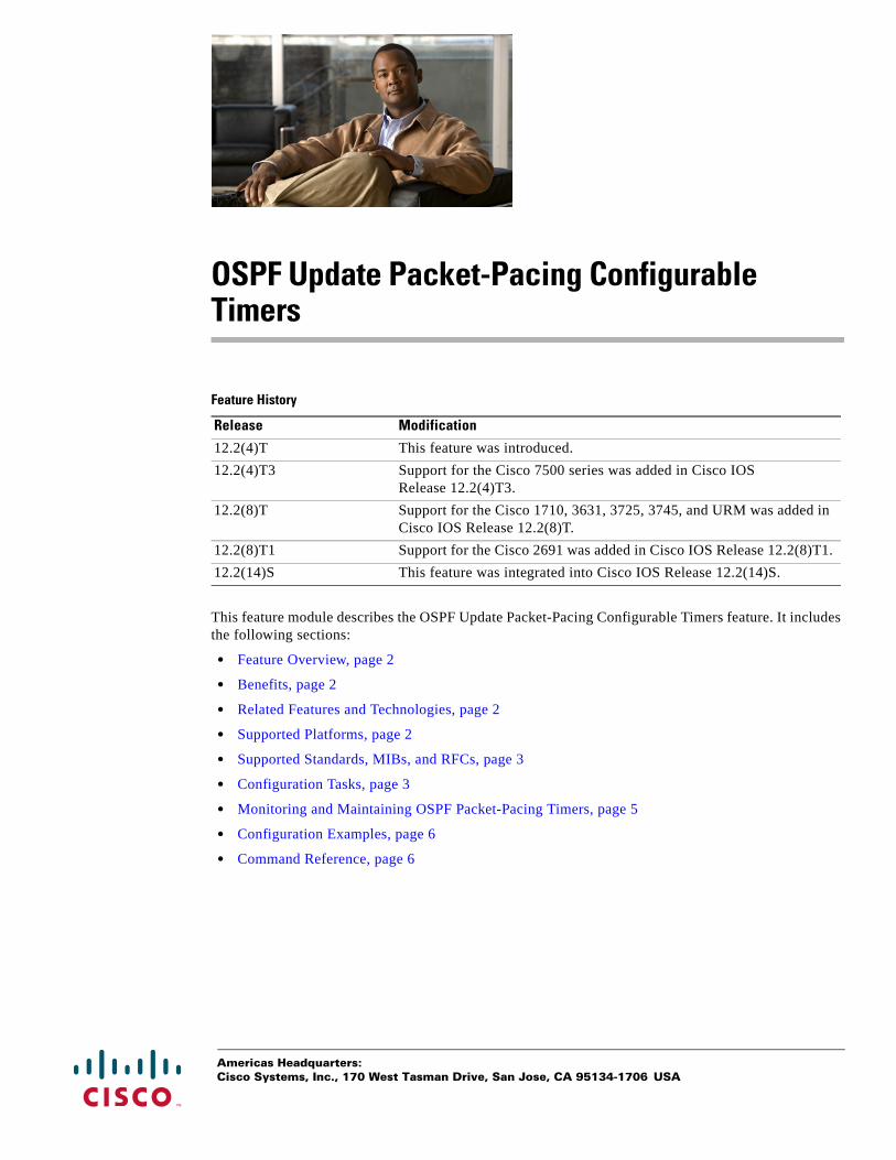
Americas Headquarters:Cisco Systems, Inc., 170 West Tasman Drive, San Jose, CA 95134-1706 USA
OSPF Update Packet-Pacing Configurable Timers
Feature History
This feature module describes the OSPF Update Packet-Pacing Configurable Timers feature. It includes the following sections:
• Feature Overview, page 2
• Benefits, page 2
• Related Features and Technologies, page 2
• Supported Platforms, page 2
• Supported Standards, MIBs, and RFCs, page 3
• Configuration Tasks, page 3
• Monitoring and Maintaining OSPF Packet-Pacing Timers, page 5
• Configuration Examples, page 6
• Command Reference, page 6
Release Modification
12.2(4)T This feature was introduced.
12.2(4)T3 Support for the Cisco 7500 series was added in Cisco IOS Release 12.2(4)T3.
12.2(8)T Support for the Cisco 1710, 3631, 3725, 3745, and URM was added in Cisco IOS Release 12.2(8)T.
12.2(8)T1 Support for the Cisco 2691 was added in Cisco IOS Release 12.2(8)T1.
12.2(14)S This feature was integrated into Cisco IOS Release 12.2(14)S.

OSPF Update Packet-Pacing Configurable Timers Feature Overview
2
Feature OverviewIn rare situations, you might need to change Open Shortest Path First (OSPF) packet-pacing default timers to mitigate CPU or buffer utilization issues associated with flooding very large numbers of link-state advertisements (LSAs). The OSPF Update Packet-Pacing Configurable Timers feature allows you to configure the rate at which OSPF LSA flood pacing, retransmission pacing, and group pacing updates occur.
Configuring OSPF flood pacing timers allows you to control interpacket spacing between consecutive link-state update packets in the OSPF transmission queue. Configuring OSPF retransmission pacing timers allows you to control interpacket spacing between consecutive link-state update packets in the OSPF retransmission queue. Cisco IOS software groups the periodic refresh of LSAs to improve the LSA packing density for the refreshes in large topologies. The group timer controls the interval used for group LSA refreshment; however, this timer does not change the frequency that individual LSAs are refreshed (the default refresh occurs every 30 minutes).
Note The default settings for OSPF packet pacing timers are suitable for the majority of OSPF deployments. You should change the default timers only as a last resort.
BenefitsThe OSPF Update Packet-Pacing Configurable Timers feature provides the administrator with a mechanism to control the rate at which LSA updates occur in order to reduce high CPU or buffer utilization that can occur when an area is flooded with a very large number of LSAs.
RestrictionsDo not change the packet pacing timers unless all other options to meet OSPF packet flooding requirements have been exhausted. Specifically, network operators should prefer summarization, stub area usage, queue tuning, and buffer tuning before changing the default timers. Furthermore, there are no guidelines for changing timer values; each OSPF deployment is unique and should be considered on a case-by-case basis. The network operator assumes risks associated with changing the default timer values.
Related Features and TechnologiesThe OSPF Update Packet-Pacing Configurable Timers feature is an extension of the OSPF routing protocol. For more information about configuring OSPF, packet pacing, area border router (ABR) and autonomous system boundary router (ASBR) summarization, and stub router configuration, refer to the “Configuring OSPF” module of the Cisco IOS IP Routing Configuration Guide and the Cisco IOS IP Routing: OSPF Command Reference.
Supported PlatformsThe OSPF Update Packet-Pacing Configurable Timers feature is supported by the following platforms in Cisco IOS Release 12.2(14)S that support OSPF:

OSPF Update Packet-Pacing Configurable Timers Supported Standards, MIBs, and RFCs
3
• Cisco 7200 series
• Cisco 7400 series
• Cisco 7500 series
Determining Platform Support Through Cisco Feature Navigator
Cisco IOS software is packaged in feature sets that support specific platforms. To get updated information regarding platform support for this feature, access Cisco Feature Navigator. Cisco Feature Navigator dynamically updates the list of supported platforms as new platform support is added for the feature.
Cisco Feature Navigator is a web-based tool that enables you to determine which Cisco IOS software images support a specific set of features and which features are supported in a specific Cisco IOS image. You can search by feature or release. Under the release section, you can compare releases side by side to display both the features unique to each software release and the features in common.
Cisco Feature Navigator is updated regularly when major Cisco IOS software releases and technology releases occur. For the most current information, go to the Cisco Feature Navigator home page at the following URL:
http://www.cisco.com/go/fn
Availability of Cisco IOS Software Images
Platform support for particular Cisco IOS software releases is dependent on the availability of the software images for those platforms. Software images for some platforms may be deferred, delayed, or changed without prior notice. For updated information about platform support and availability of software images for each Cisco IOS software release, refer to the online release notes or, if supported, Cisco Feature Navigator.
Supported Standards, MIBs, and RFCsStandards
No new or modified standards are supported by this feature.
MIBs
No new or modified MIBs are supported by this feature.
To obtain lists of supported MIBs by platform and Cisco IOS release, and to download MIB modules, go to the Cisco MIB website on Cisco.com at the following URL:
http://www.cisco.com/public/sw-center/netmgmt/cmtk/mibs.shtml
RFCs
No new or modified RFCs are supported by this feature.
Configuration TasksSee the following sections for configuration tasks for the OSPF Update Packet-Pacing Configurable Timers feature. Each task in the list is identified as either required or optional:
• Configuring OSPF Packet-Pacing Timers (required)
OSPF Update Packet-Pacing Configurable Timers Configuration Tasks
4
• Verifying OSPF Packet-Pacing Timers (optional)
Configuring OSPF Packet-Pacing TimersTo configure a flood packet pacing timer, use the following commands beginning in router configuration mode:
To configure a retransmission packet pacing timer, use the following commands beginning in router configuration mode:
To configure a group packet pacing timer, use the following commands beginning in router configuration mode:
Verifying OSPF Packet-Pacing TimersTo verify that OSPF packet pacing has been configured, use the show ip ospf privileged EXEC command. The output of the show ip ospf command will display the type and delay time of the configurable pacing timers (flood, retransmission, group). The following example output is from the show ip ospf command:
Router# show ip ospf Routing Process "ospf 1" with ID 10.0.0.1 and Domain ID 10.20.0.1 Supports only single TOS(TOS0) routes Supports opaque LSA SPF schedule delay 5 secs, Hold time between two SPFs 10 secs Minimum LSA interval 5 secs. Minimum LSA arrival 1 secs
Command Purpose
Step 1 Router(config)# router ospf process-id Places the router in router configuration mode and enables an OSPF routing process.
Step 2 Router(config-router)# timers pacing flood milliseconds
Configures a flood packet pacing timer delay (in milliseconds).
Command Purpose
Step 1 Router(config)# router ospf process-id Places the router in router configuration mode and enables an OSPF routing process.
Step 2 Router(config-router)# timers pacing retransmission milliseconds
Configures a retransmission packet pacing timer delay (in milliseconds).
Command Purpose
Step 1 Router(config)# router ospf process-id Places the router in router configuration mode and enables an OSPF routing process.
Step 2 Router(config-router)# timers pacing lsa-group seconds Configures an LSA group packet pacing timer delay (in seconds).
OSPF Update Packet-Pacing Configurable Timers Monitoring and Maintaining OSPF Packet-Pacing Timers
5
LSA group pacing timer 100 secs Interface flood pacing timer 55 msecs Retransmission pacing timer 100 msecs Number of external LSA 0. Checksum Sum 0x0 Number of opaque AS LSA 0. Checksum Sum 0x0 Number of DCbitless external and opaque AS LSA 0 Number of DoNotAge external and opaque AS LSA 0 Number of areas in this router is 2. 2 normal 0 stub 0 nssa External flood list length 0 Area BACKBONE(0) Number of interfaces in this area is 2 Area has message digest authentication SPF algorithm executed 4 times Area ranges are Number of LSA 4. Checksum Sum 0x29BEB Number of opaque link LSA 0. Checksum Sum 0x0 Number of DCbitless LSA 3 Number of indication LSA 0 Number of DoNotAge LSA 0 Flood list length 0 Area 172.16.26.0 Number of interfaces in this area is 0 Area has no authentication SPF algorithm executed 1 times Area ranges are 192.168.0.0/16 Passive Advertise Number of LSA 1. Checksum Sum 0x44FD Number of opaque link LSA 0. Checksum Sum 0x0 Number of DCbitless LSA 1 Number of indication LSA 1 Number of DoNotAge LSA 0 Flood list length 0
Troubleshooting TipsIf the number of OSPF packet retransmissions rapidly increases, increase the value of the packet pacing timers. The number of OSPF packet retransmissions is displayed in the output of the show ip ospf neighbor command.
Monitoring and Maintaining OSPF Packet-Pacing TimersTo monitor and maintain OSPF packet-pacing timers, use the following commands in privileged EXEC mode:
Command PurposeRouter# show ip ospf Displays general information about OSPF routing
processes.
router# show ip ospf neighbor Displays OSPF neighbor information on a per-interface basis.
Router# clear ip ospf redistribution Clears route redistribution based on the OSPF routing process ID.
OSPF Update Packet-Pacing Configurable Timers Configuration Examples
6
Configuration ExamplesThis section provides the following configuration examples:
• Flood Pacing Example
• Retransmission Pacing Example
• Group Pacing Example
Flood Pacing ExampleThe following example configures LSA flood pacing updates to occur in 50-millisecond intervals for OSPF routing process 1:
Router(config)# router ospf 1Router(config-router)# timers pacing flood 50
Retransmission Pacing ExampleThe following example configures LSA flood pacing updates to occur in 100-millisecond intervals for OSPF routing process 1:
Router(config)# router ospf 1Router(config-router)# timers pacing retransmission 100
Group Pacing ExampleThe following example configures OSPF group pacing updates between LSA groups to occur in 75-second intervals for OSPF routing process 1:
Router(config)# router ospf 1Router(config-router)# timers pacing lsa-group 75
Command ReferenceThe following commands are introduced or modified in the feature or features documented in this module. For information about these commands, see the Cisco IOS IP Routing: OSPF Command Reference. For information about all Cisco IOS commands, go to the Command Lookup Tool at http://tools.cisco.com/Support/CLILookup or to the Cisco IOS Master Commands List.
• timers pacing flood
• timers pacing lsa-group
• timers pacing retransmission
• show ip ospf
CCDE, CCENT, CCSI, Cisco Eos, Cisco HealthPresence, Cisco IronPort, the Cisco logo, Cisco Nurse Connect, Cisco Pulse, Cisco SensorBase, Cisco StackPower, Cisco StadiumVision, Cisco TelePresence, Cisco Unified Computing System, Cisco WebEx, DCE, Flip Channels, Flip for Good, Flip Mino, Flipshare (Design), Flip Ultra, Flip Video, Flip Video (Design), Instant Broadband, and Welcome to the Human Network are trademarks; Changing the Way We Work, Live, Play, and Learn, Cisco Capital, Cisco Capital (Design), Cisco:Financed (Stylized), Cisco Store, Flip Gift Card,
OSPF Update Packet-Pacing Configurable Timers Command Reference
7
and One Million Acts of Green are service marks; and Access Registrar, Aironet, AllTouch, AsyncOS, Bringing the Meeting To You, Catalyst, CCDA, CCDP, CCIE, CCIP, CCNA, CCNP, CCSP, CCVP, Cisco, the Cisco Certified Internetwork Expert logo, Cisco IOS, Cisco Lumin, Cisco Nexus, Cisco Press, Cisco Systems, Cisco Systems Capital, the Cisco Systems logo, Cisco Unity, Collaboration Without Limitation, Continuum, EtherFast, EtherSwitch, Event Center, Explorer, Follow Me Browsing, GainMaker, iLYNX, IOS, iPhone, IronPort, the IronPort logo, Laser Link, LightStream, Linksys, MeetingPlace, MeetingPlace Chime Sound, MGX, Networkers, Networking Academy, PCNow, PIX, PowerKEY, PowerPanels, PowerTV, PowerTV (Design), PowerVu, Prisma, ProConnect, ROSA, SenderBase, SMARTnet, Spectrum Expert, StackWise, WebEx, and the WebEx logo are registered trademarks of Cisco Systems, Inc. and/or its affiliates in the United States and certain other countries.
All other trademarks mentioned in this document or website are the property of their respective owners. The use of the word partner does not imply a partnership relationship between Cisco and any other company. (0910R)
Any Internet Protocol (IP) addresses used in this document are not intended to be actual addresses. Any examples, command display output, and figures included in the document are shown for illustrative purposes only. Any use of actual IP addresses in illustrative content is unintentional and coincidental.
© 2008 Cisco Systems, Inc. All rights reserved.

OSPF Update Packet-Pacing Configurable Timers Command Reference
8
Americas Headquarters:Cisco Systems, Inc., 170 West Tasman Drive, San Jose, CA 95134-1706 USA
OSPF Sham-Link Support for MPLS VPN
Feature History
This document describes how to configure and use a sham-link to connect Virtual Private Network (VPN) client sites that run the Open Shortest Path First (OSPF) protocol and share backdoor OSPF links in a Multiprotocol Label Switching (MPLS) VPN configuration.
This document includes the following sections:
• Feature Overview, page 1
• Supported Platforms, page 8
• Supported Standards, MIBs, and RFCs, page 9
• Prerequisites, page 10
• Configuration Tasks, page 10
• Configuration Examples, page 12
• Command Reference, page 12
• Glossary, page 13
Feature Overview
Using OSPF in PE-CE Router ConnectionsIn an MPLS VPN configuration, the OSPF protocol is one way you can connect customer edge (CE) routers to service provider edge (PE) routers in the VPN backbone. OSPF is often used by customers that run OSPF as their intrasite routing protocol, subscribe to a VPN service, and want to exchange routing information between their sites using OSPF (during migration or on a permanent basis) over an MPLS VPN backbone.
Release Modification
12.2(8)T This feature was introduced.
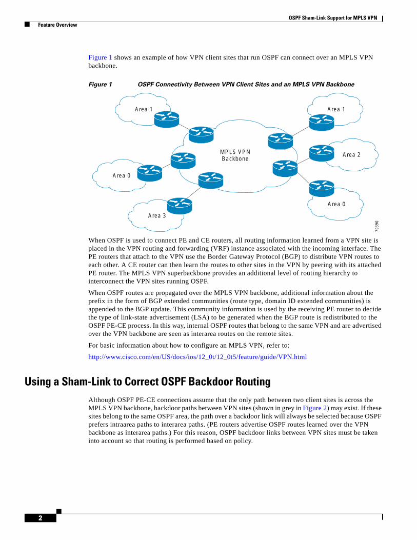
OSPF Sham-Link Support for MPLS VPN Feature Overview
2
Figure 1 shows an example of how VPN client sites that run OSPF can connect over an MPLS VPN backbone.
Figure 1 OSPF Connectivity Between VPN Client Sites and an MPLS VPN Backbone
When OSPF is used to connect PE and CE routers, all routing information learned from a VPN site is placed in the VPN routing and forwarding (VRF) instance associated with the incoming interface. The PE routers that attach to the VPN use the Border Gateway Protocol (BGP) to distribute VPN routes to each other. A CE router can then learn the routes to other sites in the VPN by peering with its attached PE router. The MPLS VPN superbackbone provides an additional level of routing hierarchy to interconnect the VPN sites running OSPF.
When OSPF routes are propagated over the MPLS VPN backbone, additional information about the prefix in the form of BGP extended communities (route type, domain ID extended communities) is appended to the BGP update. This community information is used by the receiving PE router to decide the type of link-state advertisement (LSA) to be generated when the BGP route is redistributed to the OSPF PE-CE process. In this way, internal OSPF routes that belong to the same VPN and are advertised over the VPN backbone are seen as interarea routes on the remote sites.
For basic information about how to configure an MPLS VPN, refer to:
http://www.cisco.com/en/US/docs/ios/12_0t/12_0t5/feature/guide/VPN.html
Using a Sham-Link to Correct OSPF Backdoor RoutingAlthough OSPF PE-CE connections assume that the only path between two client sites is across the MPLS VPN backbone, backdoor paths between VPN sites (shown in grey in Figure 2) may exist. If these sites belong to the same OSPF area, the path over a backdoor link will always be selected because OSPF prefers intraarea paths to interarea paths. (PE routers advertise OSPF routes learned over the VPN backbone as interarea paths.) For this reason, OSPF backdoor links between VPN sites must be taken into account so that routing is performed based on policy.
MPLS VPNBackbone
Area 1Area 1
Area 0
Area 3
Area 2
Area 0
7039
0
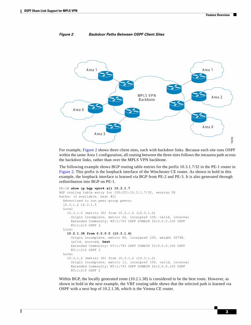
OSPF Sham-Link Support for MPLS VPN Feature Overview
3
Figure 2 Backdoor Paths Between OSPF Client Sites
For example, Figure 2 shows three client sites, each with backdoor links. Because each site runs OSPF within the same Area 1 configuration, all routing between the three sites follows the intraarea path across the backdoor links, rather than over the MPLS VPN backbone.
The following example shows BGP routing table entries for the prefix 10.3.1.7/32 in the PE-1 router in Figure 2. This prefix is the loopback interface of the Winchester CE router. As shown in bold in this example, the loopback interface is learned via BGP from PE-2 and PE-3. It is also generated through redistribution into BGP on PE-1.
PE-1# show ip bgp vpnv4 all 10.3.1.7BGP routing table entry for 100:251:10.3.1.7/32, version 58Paths: (3 available, best #2) Advertised to non peer-group peers: 10.3.1.2 10.3.1.5 Local 10.3.1.5 (metric 30) from 10.3.1.5 (10.3.1.5) Origin incomplete, metric 22, localpref 100, valid, internal Extended Community: RT:1:793 OSPF DOMAIN ID:0.0.0.100 OSPF RT:1:2:0 OSPF 2 Local 10.2.1.38 from 0.0.0.0 (10.3.1.6) Origin incomplete, metric 86, localpref 100, weight 32768, valid, sourced, best Extended Community: RT:1:793 OSPF DOMAIN ID:0.0.0.100 OSPF RT:1:2:0 OSPF 2 Local 10.3.1.2 (metric 30) from 10.3.1.2 (10.3.1.2) Origin incomplete, metric 11, localpref 100, valid, internal Extended Community: RT:1:793 OSPF DOMAIN ID:0.0.0.100 OSPF RT:1:2:0 OSPF 2
Within BGP, the locally generated route (10.2.1.38) is considered to be the best route. However, as shown in bold in the next example, the VRF routing table shows that the selected path is learned via OSPF with a next hop of 10.2.1.38, which is the Vienna CE router.
MPLS VPNBackbone
Area 1Area 1
Area 0
Area 3
Area 2
Area 0
7039
0
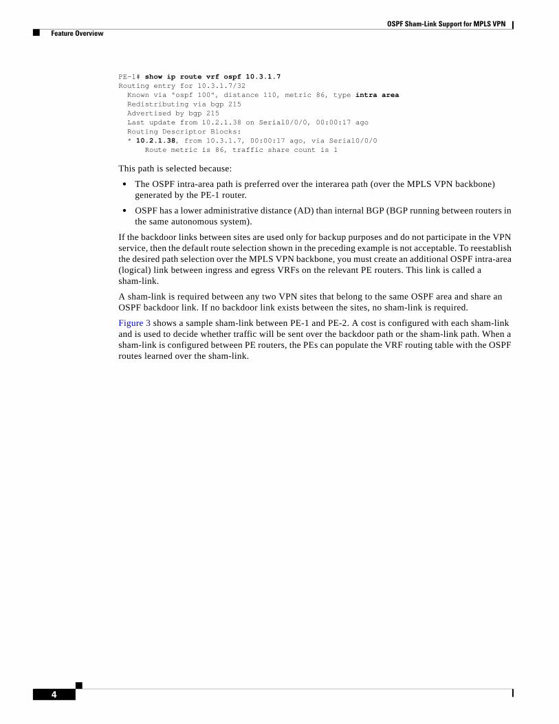
OSPF Sham-Link Support for MPLS VPN Feature Overview
4
PE-1# show ip route vrf ospf 10.3.1.7Routing entry for 10.3.1.7/32 Known via "ospf 100", distance 110, metric 86, type intra area Redistributing via bgp 215 Advertised by bgp 215 Last update from 10.2.1.38 on Serial0/0/0, 00:00:17 ago Routing Descriptor Blocks: * 10.2.1.38, from 10.3.1.7, 00:00:17 ago, via Serial0/0/0 Route metric is 86, traffic share count is 1
This path is selected because:
• The OSPF intra-area path is preferred over the interarea path (over the MPLS VPN backbone) generated by the PE-1 router.
• OSPF has a lower administrative distance (AD) than internal BGP (BGP running between routers in the same autonomous system).
If the backdoor links between sites are used only for backup purposes and do not participate in the VPN service, then the default route selection shown in the preceding example is not acceptable. To reestablish the desired path selection over the MPLS VPN backbone, you must create an additional OSPF intra-area (logical) link between ingress and egress VRFs on the relevant PE routers. This link is called a sham-link.
A sham-link is required between any two VPN sites that belong to the same OSPF area and share an OSPF backdoor link. If no backdoor link exists between the sites, no sham-link is required.
Figure 3 shows a sample sham-link between PE-1 and PE-2. A cost is configured with each sham-link and is used to decide whether traffic will be sent over the backdoor path or the sham-link path. When a sham-link is configured between PE routers, the PEs can populate the VRF routing table with the OSPF routes learned over the sham-link.

OSPF Sham-Link Support for MPLS VPN Feature Overview
5
Figure 3 Using a Sham-Link Between PE Routers to Connect OSPF Client Sites
Because the sham-link is seen as an intra-area link between PE routers, an OSPF adjacency is created and database exchange (for the particular OSPF process) occurs across the link. The PE router can then flood LSAs between sites from across the MPLS VPN backbone. As a result, the desired intra-area connectivity is created.
The section, “Creating a Sham-Link”, describes how to configure a sham-link between two PE routers. For more information about how to configure OSPF, refer to:
Configuring OSPF
Sham-Link Configuration ExampleThe example in this section is designed to show how a sham-link is used only to affect the OSPF intra-area path selection of the PE and CE routers. The PE router also uses the information received from MP-BGP to set the outgoing label stack of incoming packets, and to decide to which egress PE router to label switch the packets.
Figure 4 shows a sample MPLS VPN topology in which a sham-link configuration is necessary. A VPN client has three sites, each with a backdoor link. Two sham-links have been configured, one between PE-1 and PE-2, and another between PE-2 and PE-3. A sham-link between PE-1 and PE-3 is not necessary in this configuration because the Vienna and Winchester sites do not share a backdoor link.
MPLS VPN Backbone
Area 1Winchester
10.3.1.7
Brighton 7039
2
Net=10.3.1.7Type-1 LSA
PE310.3.1.2
MP-BGP
Area 1Stockholm10.3.1.3
Net=10.3.1.7Type-1 LSA
Area 1 Vienna10.3.1.38
Net=10.3.1.7Type-1 LSA
Net=10.3.1.7Route-type 1:2:0
Net=10.3.1.7Route-type 1:2:0
Sham-linkSham-link
PE210.3.1.5
PE110.3.1.6
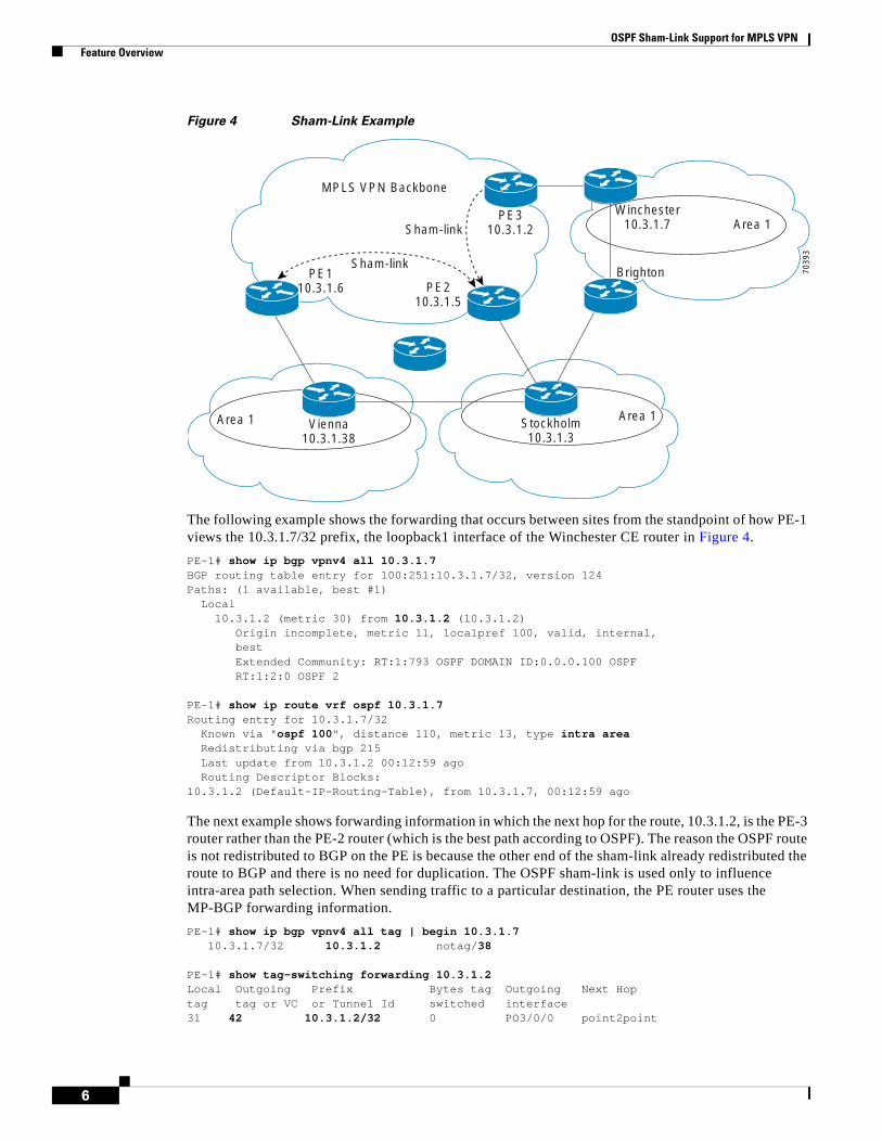
OSPF Sham-Link Support for MPLS VPN Feature Overview
6
Figure 4 Sham-Link Example
The following example shows the forwarding that occurs between sites from the standpoint of how PE-1 views the 10.3.1.7/32 prefix, the loopback1 interface of the Winchester CE router in Figure 4.
PE-1# show ip bgp vpnv4 all 10.3.1.7BGP routing table entry for 100:251:10.3.1.7/32, version 124Paths: (1 available, best #1) Local 10.3.1.2 (metric 30) from 10.3.1.2 (10.3.1.2) Origin incomplete, metric 11, localpref 100, valid, internal, best Extended Community: RT:1:793 OSPF DOMAIN ID:0.0.0.100 OSPF RT:1:2:0 OSPF 2
PE-1# show ip route vrf ospf 10.3.1.7Routing entry for 10.3.1.7/32 Known via "ospf 100", distance 110, metric 13, type intra area Redistributing via bgp 215 Last update from 10.3.1.2 00:12:59 ago Routing Descriptor Blocks:10.3.1.2 (Default-IP-Routing-Table), from 10.3.1.7, 00:12:59 ago
The next example shows forwarding information in which the next hop for the route, 10.3.1.2, is the PE-3 router rather than the PE-2 router (which is the best path according to OSPF). The reason the OSPF route is not redistributed to BGP on the PE is because the other end of the sham-link already redistributed the route to BGP and there is no need for duplication. The OSPF sham-link is used only to influence intra-area path selection. When sending traffic to a particular destination, the PE router uses the MP-BGP forwarding information.
PE-1# show ip bgp vpnv4 all tag | begin 10.3.1.7 10.3.1.7/32 10.3.1.2 notag/38
PE-1# show tag-switching forwarding 10.3.1.2Local Outgoing Prefix Bytes tag Outgoing Next Hop tag tag or VC or Tunnel Id switched interface 31 42 10.3.1.2/32 0 PO3/0/0 point2point
MPLS VPN Backbone
Area 1Winchester
10.3.1.7
Brighton 7039
3
PE310.3.1.2
PE210.3.1.5
PE110.3.1.6
Sham-link
Sham-link
Area 1Stockholm10.3.1.3
Area 1 Vienna10.3.1.38

OSPF Sham-Link Support for MPLS VPN Feature Overview
7
PE-1# show ip cef vrf ospf 10.3.1.710.3.1.7/32, version 73, epoch 0, cached adjacency to POS3/0/00 packets, 0 bytes tag information set local tag: VPN-route-head fast tag rewrite with PO3/0/0, point2point, tags imposed: {42 38} via 10.3.1.2, 0 dependencies, recursive next hop 10.1.1.17, POS3/0/0 via 10.3.1.2/32 valid cached adjacency tag rewrite with PO3/0/0, point2point, tags imposed: {42 38}
If a prefix is learned across the sham-link and the path via the sham-link is selected as the best, the PE router does not generate an MP-BGP update for the prefix. It is not possible to route traffic from one sham-link over another sham-link.
In the following example, PE-2 shows how an MP-BGP update for the prefix is not generated. Although 10.3.1.7/32 has been learned via OSPF across the sham-link as shown in bold, no local generation of a route into BGP is performed. The only entry within the BGP table is the MP-BGP update received from PE-3 (the egress PE router for the 10.3.1.7/32 prefix).
PE-2# show ip route vrf ospf 10.3.1.7Routing entry for 10.3.1.7/32 Known via "ospf 100", distance 110, metric 12, type intra area Redistributing via bgp 215 Last update from 10.3.1.2 00:00:10 ago Routing Descriptor Blocks: * 10.3.1.2 (Default-IP-Routing-Table), from 10.3.1.7, 00:00:10 ago Route metric is 12, traffic share count is 1
PE-2# show ip bgp vpnv4 all 10.3.1.7BGP routing table entry for 100:251:10.3.1.7/32, version 166Paths: (1 available, best #1) Not advertised to any peer Local 10.3.1.2 (metric 30) from 10.3.1.2 (10.3.1.2) Origin incomplete, metric 11, localpref 100, valid, internal, best Extended Community: RT:1:793 OSPF DOMAIN ID:0.0.0.100 OSPF RT:1:2:0 OSPF 2
The PE router uses the information received from MP-BGP to set the ongoing label stack of incoming packets, and to decide to which egress PE router to label switch the packets.
Benefits
Client Site Connection Across the MPLS VPN Backbone
A sham-link overcomes the OSPF default behavior for selecting an intra-area backdoor route between VPN sites instead of an interarea (PE-to-PE) route. A sham-link ensures that OSPF client sites that share a backdoor link can communicate over the MPLS VPN backbone and participate in VPN services.
Flexible Routing in an MPLS VPN Configuration
In an MPLS VPN configuration, the OSPF cost configured with a sham-link allows you to decide if OSPF client site traffic will be routed over a backdoor link or through the VPN backbone.

OSPF Sham-Link Support for MPLS VPN Supported Platforms
8
RestrictionsWhen OSPF is used as a protocol between PE and CE routers, the OSPF metric is preserved when routes are advertised over the VPN backbone. The metric is used on the remote PE routers to select the correct route. For this reason, you should not modify the metric value when OSPF is redistributed to BGP, and when BGP is redistributed to OSPF. If you modify the metric value, routing loops may occur.
Related Features and Technologies• MPLS
• OSPF
• BGP
Related Documents• Cisco IOS IP Routing: OSPF Command Reference
http://www.cisco.com/en/US/docs/ios/iproute_ospf/command/reference/iro_book.html
• MPLS Virtual Private Networks
http://www.cisco.com/en/US/docs/ios/12_0t/12_0t5/feature/guide/VPN.html
• Configuring OSPF
http://www.cisco.com/en/US/docs/ios/iproute_ospf/configuration/guide/iro_cfg.html
• Cisco IOS IP Routing: BGP Configuration Guide, Release 15.0
http://www.cisco.com/en/US/docs/ios/iproute_bgp/configuration/guide/15_0/irg_15_0_book.html
• RFC 1163, A Border Gateway Protocol
• RFC 1164, Application of the Border Gateway Protocol in the Internet
• RFC 2283, Multiprotocol Extensions for BGP-4
• RFC 2328, Open Shortest Path First, Version 2
• RFC 2547, BGP/MPLS VPNs
Supported Platforms• Cisco 1400 series
• Cisco 1600
• Cisco 1600R
• Cisco 1710
• Cisco 1720
• Cisco 1721
• Cisco 1750
• Cisco 1751
OSPF Sham-Link Support for MPLS VPN Supported Standards, MIBs, and RFCs
9
• Cisco 2420
• Cisco 2600
• Cisco 2691
• Cisco 3620
• Cisco 3631
• Cisco 3640
• Cisco 3660
• Cisco 3725
• Cisco 3745
• Cisco 7100
• Cisco 7200
• Cisco 7500
• Cisco 7700
• URM
• Cisco uBR7200
Determining Platform Support Through Cisco Feature Navigator
Cisco IOS software is packaged in feature sets that support specific platforms. To get updated information regarding platform support for this feature, access Cisco Feature Navigator. Cisco Feature Navigator dynamically updates the list of supported platforms as new platform support is added for the feature.
Cisco Feature Navigator is a web-based tool that enables you to quickly determine which Cisco IOS software images support a specific set of features and which features are supported in a specific Cisco IOS image. You can search by feature or release. Under the release section, you can compare releases side by side to display both the features unique to each software release and the features in common.
Cisco Feature Navigator is updated regularly when major Cisco IOS software releases and technology releases occur. For the most current information, go to the Cisco Feature Navigator home page at the following URL:
http://www.cisco.com/go/fn
Supported Standards, MIBs, and RFCsStandards
No new or modified standards are supported by this feature.
MIBs
No new or modified MIBs are supported by this feature.
To obtain lists of supported MIBs by platform and Cisco IOS release, and to download MIB modules, go to the Cisco MIB website on Cisco.com at the following URL:
http://www.cisco.com/public/sw-center/netmgmt/cmtk/mibs.shtml
OSPF Sham-Link Support for MPLS VPN Prerequisites
10
RFCs
No new or modified RFCs are supported by this feature.
PrerequisitesBefore you can configure a sham-link in an MPLS VPN, you must first enable OSPF as follows:
• Create an OSPF routing process.
• Specify the range of IP addresses to be associated with the routing process.
• Assign area IDs to be associated with the range of IP addresses.
For more information on these OSPF configuration procedures, go to:
http://www.cisco.com/en/US/docs/ios/iproute_ospf/command/reference/iro_book.html
Configuration TasksSee the following sections for configuration tasks for the sham-link feature. Each task in the list is identified as either required or optional.
• Creating a Sham-Link (required)
• Verifying Sham-Link Creation (optional)
Creating a Sham-LinkBefore you create a sham-link between PE routers in an MPLS VPN, you must:
• Configure a separate /32 address on the remote PE so that OSPF packets can be sent over the VPN backbone to the remote end of the sham-link. The /32 address must meet the following criteria:
– Belong to a VRF.
– Not be advertised by OSPF.
– Be advertised by BGP.
You can use the /32 address for other sham-links.
• Associate the sham-link with an existing OSPF area.
To create a sham-link, use the following commands starting in EXEC mode:
Command Purpose
Step 1 Router1# configure terminal Enters global configuration mode on the first PE router.
Step 2 Router1(config)# interface loopback interface-number
Creates a loopback interface to be used as an endpoint of the sham-link on PE-1 and enters interface configuration mode.
Step 3 Router1(config-if)# ip vrf forwarding vrf-name
Associates the loopback interface with a VRF. Removes the IP address.
Step 4 Router1(config-if)# ip address ip-address mask
Reconfigures the IP address of the loopback interface on PE-1.
Step 5 Router1(config-if)# end Returns to global configuration mode.
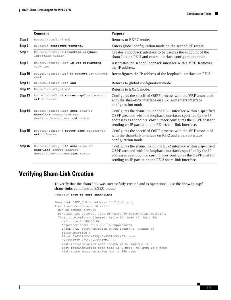
OSPF Sham-Link Support for MPLS VPN Configuration Tasks
11
Verifying Sham-Link CreationTo verify that the sham-link was successfully created and is operational, use the show ip ospf sham-links command in EXEC mode:
Router1# show ip ospf sham-links
Sham Link OSPF_SL0 to address 10.2.1.2 is upArea 1 source address 10.2.1.1 Run as demand circuit DoNotAge LSA allowed. Cost of using 40 State POINT_TO_POINT, Timer intervals configured, Hello 10, Dead 40, Wait 40, Hello due in 00:00:04 Adjacency State FULL (Hello suppressed) Index 2/2, retransmission queue length 4, number of retransmission 0 First 0x63311F3C(205)/0x63311FE4(59) Next 0x63311F3C(205)/0x63311FE4(59) Last retransmission scan length is 0, maximum is 0 Last retransmission scan time is 0 msec, maximum is 0 msec Link State retransmission due in 360 msec
Step 6 Router1(config)# end Returns to EXEC mode.
Step 7 Router2# configure terminal Enters global configuration mode on the second PE router.
Step 8 Router2(config)# interface loopback interface-number
Creates a loopback interface to be used as the endpoint of the sham-link on PE-2 and enters interface configuration mode.
Step 9 Router2(config-if)# ip vrf forwarding vrf-name
Associates the second loopback interface with a VRF. Removes the IP address.
Step 10 Router2(config-if)# ip address ip-address mask
Reconfigures the IP address of the loopback interface on PE-2.
Step 11 Router2(config-if)# end Returns to global configuration mode.
Step 12 Router1(config)# end Returns to EXEC mode.
Step 13 Router1(config)# router ospf process-id vrf vrf-name
Configures the specified OSPF process with the VRF associated with the sham-link interface on PE-1 and enters interface configuration mode.
Step 14 Router1(config-if)# area area-id sham-link source-address destination-address cost number
Configures the sham-link on the PE-1 interface within a specified OSPF area and with the loopback interfaces specified by the IP addresses as endpoints. cost number configures the OSPF cost for sending an IP packet on the PE-1 sham-link interface.
Step 15 Router2(config)# router ospf process-id vrf vrf-name
Configures the specified OSPF process with the VRF associated with the sham-link interface on PE-2 and enters interface configuration mode.
Step 16 Router2(config-if)# area area-id sham-link source-address destination-address cost number
Configures the sham-link on the PE-2 interface within a specified OSPF area and with the loopback interfaces specified by the IP addresses as endpoints. cost number configures the OSPF cost for sending an IP packet on the PE-2 sham-link interface.
Command Purpose
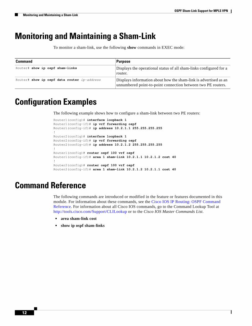
OSPF Sham-Link Support for MPLS VPN Monitoring and Maintaining a Sham-Link
12
Monitoring and Maintaining a Sham-LinkTo monitor a sham-link, use the following show commands in EXEC mode:
Configuration ExamplesThe following example shows how to configure a sham-link between two PE routers:
Router1(config)# interface loopback 1Router1(config-if)# ip vrf forwarding ospfRouter1(config-if)# ip address 10.2.1.1 255.255.255.255!Router2(config)# interface loopback 1Router2(config-if)# ip vrf forwarding ospfRouter2(config-if)# ip address 10.2.1.2 255.255.255.255!Router1(config)# router ospf 100 vrf ospfRouter1(config-if)# area 1 sham-link 10.2.1.1 10.2.1.2 cost 40!Router2(config)# router ospf 100 vrf ospfRouter2(config-if)# area 1 sham-link 10.2.1.2 10.2.1.1 cost 40
Command ReferenceThe following commands are introduced or modified in the feature or features documented in this module. For information about these commands, see the Cisco IOS IP Routing: OSPF Command Reference. For information about all Cisco IOS commands, go to the Command Lookup Tool at http://tools.cisco.com/Support/CLILookup or to the Cisco IOS Master Commands List.
• area sham-link cost
• show ip ospf sham-links
Command Purpose
Router# show ip ospf sham-links Displays the operational status of all sham-links configured for a router.
Router# show ip ospf data router ip-address Displays information about how the sham-link is advertised as an unnumbered point-to-point connection between two PE routers.
OSPF Sham-Link Support for MPLS VPN Glossary
13
GlossaryBGP—Border Gateway Protocol. Interdomain routing protocol that exchanges reachability information with other BGP systems. It is defined in RFC 1163.
CE router—customer edge router. A router that is part of a customer network and that interfaces to a provider edge (PE) router. CE routers are not aware of associated VPNs.
CEF—Cisco Express Forwarding. An advanced Layer 3 IP switching technology. CEF optimizes network performance and scalability for networks with large and dynamic traffic patterns.
OSPF—Open Shortest Path First protocol.
IGP—Interior Gateway Protocol. An Internet protocol used to exchange routing information within an autonomous system. Examples of common IGPs include IGRP, OSPF, and RIP.
LSA—link-state advertisement. A broadcast packet used by link-state protocols. The LSA contains information about neighbors and path costs and is used by the receiving router to maintain a routing table.
MPLS—Multiprotocol Label Switching. Emerging industry standard upon which tag switching is based.
PE router—provider edge router. A router that is part of a service provider network connected to a customer edge (CE) router. All VPN processing occurs in the PE router.
SPF—shortest path first calculation.
VPN—Virtual Private Network. A secure IP-based network that shares resources on one or more physical networks. A VPN contains geographically dispersed sites that can communicate securely over a shared backbone.
VRF—VPN routing and forwarding instance. A VRF consists of an IP routing table, a derived forwarding table, a set of interfaces that use the forwarding table, and a set of rules and routing protocols that determine what goes into the forwarding table. In general, a VRF includes the routing information that defines a customer VPN site that is attached to a PE router.
CCDE, CCENT, CCSI, Cisco Eos, Cisco HealthPresence, Cisco IronPort, the Cisco logo, Cisco Nurse Connect, Cisco Pulse, Cisco SensorBase, Cisco StackPower, Cisco StadiumVision, Cisco TelePresence, Cisco Unified Computing System, Cisco WebEx, DCE, Flip Channels, Flip for Good, Flip Mino, Flipshare (Design), Flip Ultra, Flip Video, Flip Video (Design), Instant Broadband, and Welcome to the Human Network are trademarks; Changing the Way We Work, Live, Play, and Learn, Cisco Capital, Cisco Capital (Design), Cisco:Financed (Stylized), Cisco Store, Flip Gift Card, and One Million Acts of Green are service marks; and Access Registrar, Aironet, AllTouch, AsyncOS, Bringing the Meeting To You, Catalyst, CCDA, CCDP, CCIE, CCIP, CCNA, CCNP, CCSP, CCVP, Cisco, the Cisco Certified Internetwork Expert logo, Cisco IOS, Cisco Lumin, Cisco Nexus, Cisco Press, Cisco Systems, Cisco Systems Capital, the Cisco Systems logo, Cisco Unity, Collaboration Without Limitation, Continuum, EtherFast, EtherSwitch, Event Center, Explorer, Follow Me Browsing, GainMaker, iLYNX, IOS, iPhone, IronPort, the IronPort logo, Laser Link, LightStream, Linksys, MeetingPlace, MeetingPlace Chime Sound, MGX, Networkers, Networking Academy, PCNow, PIX, PowerKEY, PowerPanels, PowerTV, PowerTV (Design), PowerVu, Prisma, ProConnect, ROSA, SenderBase, SMARTnet, Spectrum Expert, StackWise, WebEx, and the WebEx logo are registered trademarks of Cisco Systems, Inc. and/or its affiliates in the United States and certain other countries.
All other trademarks mentioned in this document or website are the property of their respective owners. The use of the word partner does not imply a partnership relationship between Cisco and any other company. (0910R)
Any Internet Protocol (IP) addresses used in this document are not intended to be actual addresses. Any examples, command display output, and figures included in the document are shown for illustrative purposes only. Any use of actual IP addresses in illustrative content is unintentional and coincidental.
© 2008 Cisco Systems, Inc. All rights reserved.

OSPF Sham-Link Support for MPLS VPN Glossary
14
Americas Headquarters:Cisco Systems, Inc., 170 West Tasman Drive, San Jose, CA 95134-1706 USA
OSPF Sham-Link MIB Support
First Published: October 28, 2004Last Updated: May 5, 2008
This feature introduces MIB support for the OSPF Sham-Link feature through the addition of new tables and trap MIB objects to the Cisco OSPF MIB (CISCO-OSPF-MIB) and the Cisco OSPF Trap MIB (CISCO-OSPF-TRAP-MIB). New commands have been added to enable Simple Network Management Protocol (SNMP) notifications for the Open Shortest Path First (OSPF) sham-link trap objects. Notifications are provided for errors, state changes, and retransmissions across a sham-link interface.
Finding Feature Information in This Module
Your Cisco IOS software release may not support all of the features documented in this module. To reach links to specific feature documentation in this module and to see a list of the releases in which each feature is supported, use the “Feature Information for OSPF Sham-Link MIB Support” section on page 14.
Finding Support Information for Platforms and Cisco IOS and Catalyst OS Software Images
Use Cisco Feature Navigator to find information about platform support and Cisco IOS and Catalyst OS software image support. To access Cisco Feature Navigator, go to http://www.cisco.com/go/cfn. An account on Cisco.com is not required.
Contents• Prerequisites for OSPF Sham-Link MIB Support, page 2
• Restrictions for OSPF Sham-Link MIB Support, page 2
• Information About OSPF Sham-Link MIB Support, page 2
• How to Configure OSPF Sham-Link MIB Support, page 4
• Configuration Examples for OSPF Sham-Link MIB Support, page 10
• Where to Go Next, page 12
• Additional References, page 12
• Command Reference, page 13
• Feature Information for OSPF Sham-Link MIB Support, page 14

OSPF Sham-Link MIB Support Prerequisites for OSPF Sham-Link MIB Support
2
Prerequisites for OSPF Sham-Link MIB Support• It is presumed that you already have configured an Open Shortest Path First (OSPF) sham-link.
• SNMP must be enabled on the router before notifications (traps) can be configured or before SNMP GET operations can be performed.
Restrictions for OSPF Sham-Link MIB SupportAll enhancements that are introduced by this feature are provided only by the Cisco private MIBs CISCO-OSPF-MIB and CISCO-OSPF-TRAP-MIB.
Information About OSPF Sham-Link MIB SupportThis section contains the following information:
• OSPF Sham-Links in PE-PE Router Connections, page 2
• Cisco OSPF MIB and Cisco OSPF Trap MIB Enhancements, page 2
OSPF Sham-Links in PE-PE Router ConnectionsIn a Multiprotocol Label Switching (MPLS) Virtual Private Network (VPN) configuration, a virtual connection called a sham-link can be configured to interconnect between two VPN sites that want to be in the same OSPF area. The sham-link is configured on top of the MPLS VPN tunnel that connects two provider edge (PE) routers. The OSPF packets are propagated over the sham-link. For more information on configuring sham-links, refer the OSPF Sham-Link Support for MPLS VPN feature at the following URL:
http://www.cisco.com/en/US/docs/ios/iproute_ospf/configuration/guide/iro_sham_link.html
Cisco OSPF MIB and Cisco OSPF Trap MIB EnhancementsThe OSPF Sham-Link MIB Support feature introduces MIB support for OSPF sham-links through the addition of new tables and trap MIB objects to the Cisco OSPF MIB (CISCO-OSPF-MIB) and the Cisco OSPF Trap MIB (CISCO-OSPF-TRAP-MIB) for Cisco IOS Releases 12.0(30)S, 12.3(14)T, 12.2(33)SRA, 12.2(31)SB2, and 12.2(33)SXH. New CLI has been added to enable SNMP notifications for the OSPF sham-link trap objects. Notifications are provided for errors, state changes, and retransmissions across a sham-link interface. The following sections describe the enhancements:
• OSPF Sham-Link Configuration Support, page 3
• OSPF Sham-Link Neighbor Support, page 3
• OSPF Sham-Link Interface Transition State Change Support, page 3
• OSPF Sham-Link Neighbor Transition State Change Support, page 4
• Sham-Link Errors, page 4
OSPF Sham-Link MIB Support Information About OSPF Sham-Link MIB Support
3
OSPF Sham-Link Configuration Support
The cospfShamLinksTable table object stores information about the sham-links that have been configured for the OSPF area. Beginning with Cisco IOS Releases 12.0(30)S, 12.3(14)T, 12.2(33)SRA, 12.2(31)SB2, and 12.2(33)SXH, the cospfShamLinksTable replaces the cospfShamLinkTable. The cospfShamLinksTable allows access to the following MIB objects:
• cospfShamLinksAreaId
• cospfShamLinksLocalIpAddrType
• cospfShamLinksLocalIpAddr
• cospfShamLinksRemoteIpAddrType
• cospfShamLinksRemoteIpAddr
• cospfShamLinksRetransInterval
• cospfShamLinksHelloInterval
• cospfShamLinksRtrDeadInterval
• cospfShamLinksState
• cospfShamLinksEvents
• cospfShamLinksMetric
OSPF Sham-Link Neighbor Support
The cospfShamLinkNbrTable table object describes all OSPF sham-link neighbor entries. The cospfShamLinkNbrTable allows access to the following MIB objects:
• cospfShamLinkNbrArea
• cospfShamLinkNbrIpAddrType
• cospfShamLinkNbrIpAddr
• cospfShamLinkNbrRtrId
• cospfShamLinkNbrOptions
• cospfShamLinkNbrState
• cospfShamLinkNbrEvents
• cospfShamLinkNbrLsRetransQLen
• cospfShamLinkNbrHelloSuppressed
OSPF Sham-Link Interface Transition State Change Support
The cospfShamLinksStateChange trap object is used to notify the network manager of a transition state change for the OSPF sham-link interface. The cospfShamLinksStateChange trap object replaces the original cospfShamLinkStateChange trap object for Cisco IOS Releases 12.0(30)S, 12.3(14)T, 12.2(33)SRA, and 12.2(31)SB2. The cospfShamLinksStateChange trap objects contains the following MIB objects:
• ospfRouterId
• cospfShamLinksAreaId
• cospfShamLinksLocalIpAddrType
OSPF Sham-Link MIB Support How to Configure OSPF Sham-Link MIB Support
4
• cospfShamLinksLocalIpAddr
• cospfShamLinksRemoteIpAddrType
• cospfShamLinksRemoteIpAddr
• cospfShamLinksState
OSPF Sham-Link Neighbor Transition State Change Support
The cospfShamLinkNbrStateChange trap object is used to notify the network manager of a transition state change for the OSPF sham-link neighbors. The cospfShamLinkNbrStateChange trap object contains the following MIB objects:
• ospfRouterId
• cospfShamLinkNbrArea
• cospfShamLinksLocalIpAddrType
• cospfShamLinksLocalIpAddr
• cospfShamLinkNbrIpAddrType
• cospfShamLinkNbrIpAddr
• cospfShamLinkNbrRtrId
• cospfShamLinkNbrState
Sham-Link Errors
Trap notifications are provided for OSPF sham-link configuration, authentication, and bad packet errors. These errors include the following trap objects:
• cospfShamLinkConfigError
• cospfShamLinkAuthFailure
• cospfShamLinkRxBadPacket
Note The cospfShamLinkAuthFailure trap will not be generated because Cisco IOS Releases 12.0(30)S, 12.3(14)T, 12.2(33)SRA, and 12.2(31)SB2 do not yet support authentication over sham-links. The cospfShamLinkRxBadPacket trap will not be generated because it also is not supported by Cisco IOS Releases 12.0(30)S, 12.3(14)T, 12.2(33)SRA, and 12.2(31)SB2. However, the information can be retrieved from the existing OSPF bad packet traps.
How to Configure OSPF Sham-Link MIB SupportThis section describes the configuration tasks for the OSPF Sham-Link MIB Support feature. Each task in the list is identified as either required or optional.
• Configuring the Router to Send SNMP Notifications, page 5 (required)
• Enabling OSPF Sham-Link Error Traps, page 6 (required)
• Enabling OSPF Sham-Link Retransmissions Traps, page 7 (required)
OSPF Sham-Link MIB Support How to Configure OSPF Sham-Link MIB Support
5
• Enabling OSPF Sham-Link State Change Traps, page 8 (required)
• Verifying OSPF Sham-Link MIB Traps on the Router, page 10 (optional)
Configuring the Router to Send SNMP NotificationsPerform this task to enable the router to send SNMP notifications (traps or informs) defined in the OSPF MIBs. SNMP notifications can be configured on the router and GET operations can be performed from an external management station only after MIB support is enabled.
OSPF Configuration Error Notifications
To enable the sending of OSPF configuration errors notifications, enable the following traps:
• cospfShamLinkConfigError
• cospfShamLinkAuthFailure
• cospfShamLinkRxBadPacket
SUMMARY STEPS
1. enable
2. show running-config
3. configure terminal
4. snmp-server host {hostname | ip-address} [vrf vrf-name] [traps | informs] [version {1 | 2c | 3 [auth | noauth | priv]}] community-string [udp-port port] [notification-type]
5. snmp-server enable traps ospf
6. end
DETAILED STEPS
Command or Action Purpose
Step 1 enable
Example:Router> enable
Enables privileged EXEC mode.
• Enter your password if prompted.
Step 2 show running-config
Example:Router# show running-config
Displays the running configuration to determine if an SNMP agent is already running.
• If no SNMP information is displayed, continue with the next step. If any SNMP information is displayed, you can modify the information or change it as needed.
Step 3 configure terminal
Example:Router# configure terminal
Enters global configuration mode.
OSPF Sham-Link MIB Support How to Configure OSPF Sham-Link MIB Support
6
Enabling OSPF Sham-Link Error TrapsNotifications are sent when OSPF sham-link configuration errors are detected. To enable the sending of sham-link configuration error notifications, enable the following cospfShamLinkConfigError trap.
SUMMARY STEPS
1. enable
2. configure terminal
3. snmp-server enable traps ospf cisco-specific errors config-error
4. snmp-server enable traps ospf cisco-specific errors shamlink [authentication [bad-packet [config] | [config [bad-packet]]]
5. end
Step 4 snmp-server host {hostname | ip-address} [vrf vrf-name] [traps | informs] [version {1 | 2c | 3 [auth | noauth | priv]}] community-string [udp-port port] [notification-type]
Example:Router(config)# snmp-server host 172.20.2.162 version 2c public ospf
Specifies a recipient (target host) for SNMP notification operations.
• If no notification-type is specified, all enabled notifications (traps or informs) will be sent to the specified host.
• If you want to send only the OSPF notifications to the specified host, you can use the optional ospf keyword as one of the notification-types. (See the example.)
Step 5 snmp-server enable traps ospf
Example:Router(config)# snmp-server enable traps ospf
Enables all SNMP notifications defined in the OSPF MIBs.
Note This step is required only if you wish to enable all OSPF traps, including the traps for OSPF sham-links.
When you enter the no snmp-server enable traps ospf command, all OSPF traps, including the OSPF sham-link trap, will be disabled.
Step 6 end
Example:Router(config)# end
Ends your configuration session and exits global configuration mode.
Command or Action Purpose
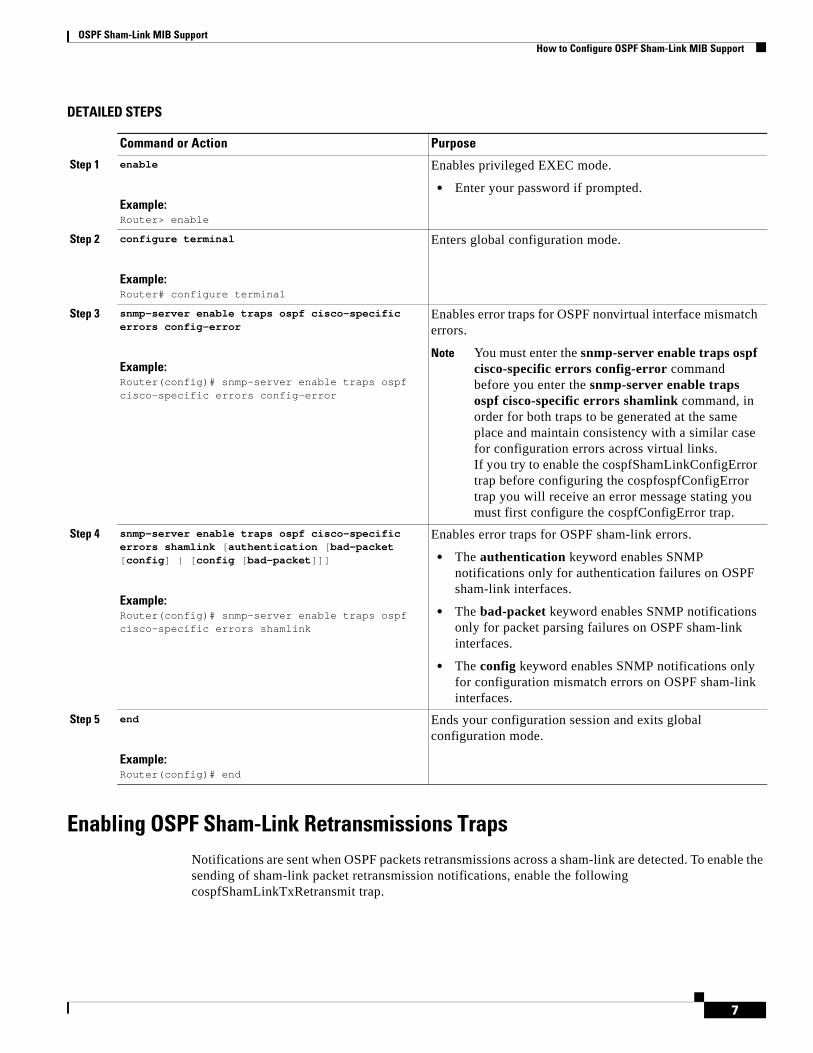
OSPF Sham-Link MIB Support How to Configure OSPF Sham-Link MIB Support
7
DETAILED STEPS
Enabling OSPF Sham-Link Retransmissions TrapsNotifications are sent when OSPF packets retransmissions across a sham-link are detected. To enable the sending of sham-link packet retransmission notifications, enable the following cospfShamLinkTxRetransmit trap.
Command or Action Purpose
Step 1 enable
Example:Router> enable
Enables privileged EXEC mode.
• Enter your password if prompted.
Step 2 configure terminal
Example:Router# configure terminal
Enters global configuration mode.
Step 3 snmp-server enable traps ospf cisco-specific errors config-error
Example:Router(config)# snmp-server enable traps ospf cisco-specific errors config-error
Enables error traps for OSPF nonvirtual interface mismatch errors.
Note You must enter the snmp-server enable traps ospf cisco-specific errors config-error command before you enter the snmp-server enable traps ospf cisco-specific errors shamlink command, in order for both traps to be generated at the same place and maintain consistency with a similar case for configuration errors across virtual links.If you try to enable the cospfShamLinkConfigError trap before configuring the cospfospfConfigError trap you will receive an error message stating you must first configure the cospfConfigError trap.
Step 4 snmp-server enable traps ospf cisco-specific errors shamlink [authentication [bad-packet [config] | [config [bad-packet]]]
Example:Router(config)# snmp-server enable traps ospf cisco-specific errors shamlink
Enables error traps for OSPF sham-link errors.
• The authentication keyword enables SNMP notifications only for authentication failures on OSPF sham-link interfaces.
• The bad-packet keyword enables SNMP notifications only for packet parsing failures on OSPF sham-link interfaces.
• The config keyword enables SNMP notifications only for configuration mismatch errors on OSPF sham-link interfaces.
Step 5 end
Example:Router(config)# end
Ends your configuration session and exits global configuration mode.
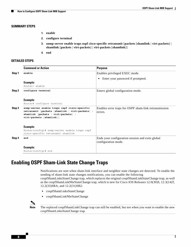
OSPF Sham-Link MIB Support How to Configure OSPF Sham-Link MIB Support
8
SUMMARY STEPS
1. enable
2. configure terminal
3. snmp-server enable traps ospf cisco-specific retransmit [packets [shamlink | virt-packets] | shamlink [packets | virt-packets] | virt-packets [shamlink]]
4. end
DETAILED STEPS
Enabling OSPF Sham-Link State Change TrapsNotifications are sent when sham-link interface and neighbor state changes are detected. To enable the sending of sham-link state changes notifications, you can enable the following cospfShamLinksStateChange trap, which replaces the original cospfShamLinkStateChange trap, as well as the cospfShamLinkNbrStateChange trap, which is new for Cisco IOS Releases 12.0(30)S, 12.3(14)T, 12.2(33)SRA, and 12.2(31)SB2:
• cospfShamLinksStateChange
• cospfShamLinkNbrStateChange
Note The replaced cospfShamLinkChange trap can still be enabled, but not when you want to enable the new cospfShamLinksStateChange trap.
Command or Action Purpose
Step 1 enable
Example:Router> enable
Enables privileged EXEC mode.
• Enter your password if prompted.
Step 2 configure terminal
Example:Router# configure terminal
Enters global configuration mode.
Step 3 snmp-server enable traps ospf cisco-specific retransmit [packets [shamlink | virt-packets] | shamlink [packets | virt-packets] | virt-packets [shamlink]]
Example:Router(config)# snmp-server enable traps ospf cisco-specific retransmit shamlink
Enables error traps for OSPF sham-link retransmission errors.
Step 4 end
Example:Router(config)# end
Ends your configuration session and exits global configuration mode.

OSPF Sham-Link MIB Support How to Configure OSPF Sham-Link MIB Support
9
SUMMARY STEPS
1. enable
2. configure terminal
3. snmp-server enable traps ospf cisco-specific state-change [nssa-trans-change | shamlink [interface | interface-old | neighbor]]
4. end
DETAILED STEPS
Command or Action Purpose
Step 1 enable
Example:Router> enable
Enables privileged EXEC mode.
• Enter your password if prompted.
Step 2 configure terminal
Example:Router# configure terminal
Enters global configuration mode.
Step 3 snmp-server enable traps ospf cisco-specific state-change [nssa-trans-change | shamlink [interface | interface-old | neighbor]]
Example:Router(config)# snmp-server enable traps ospf cisco-specific state-change
Enables all Cisco-specific OSPF state change traps including the cospfShamLinksStateChange and cospfShamLinkNbrStateChange traps that are new for Cisco IOS Releases 12.0(30)S, 12.3(14)T, 12.2(33)SRA, and 12.2(31)SB2.
• The neighbor keyword enables the OSPF sham-link neighbor state change traps.
• The interface keyword enables the OSPF sham-link interface state change traps.
• The interface-old keyword enables the original OSPF sham-link interface state change trap that is replaced by the cospfShamLinksStateChange and cospfShamLinkNbrStateChange traps for Cisco IOS Releases 12.0(30)S and 12.3(14)T.
Note You cannot enter both the interface and interface-old keywords because you cannot enable both the new and replaced sham-link interface transition state change traps. You can configure only one of the two traps, but not both.
Step 4 end
Example:Router(config)# end
Ends your configuration session and exits global configuration mode.

OSPF Sham-Link MIB Support Configuration Examples for OSPF Sham-Link MIB Support
10
Verifying OSPF Sham-Link MIB Traps on the RouterThis task verifies that you have enabled OSPF sham-link MIB support.
SUMMARY STEPS
1. enable
2. show running-config | include traps
DETAILED STEPS
Configuration Examples for OSPF Sham-Link MIB Support This section provides the following configuration examples:
• Enabling and Verifying OSPF Sham-Link Error Traps: Example, page 10
• Enabling and Verifying OSPF State Change Traps: Example, page 11
• Enabling and Verifying OSPF Sham-Link Retransmissions Traps: Example, page 12
Enabling and Verifying OSPF Sham-Link Error Traps: ExampleThe following example enables all Cisco-specific OSPF sham-link error traps. Note that the first attempt to enter the snmp-server enable traps ospf cisco-specific errors shamlink command results in an error message that the snmp-server enable traps ospf cisco-specific errors config-error command must be entered first:
Router# configure terminal
Enter configuration commands, one per line. End with CNTL/Z.
Router(config)# snmp-server enable traps ospf cisco-specific errors shamlink
% Sham-link config error trap not enabled.% Configure "cisco-specific errors config-error" first.% This requirement allows both traps to be sent.
Router(config)# snmp-server enable traps ospf cisco-specific errors config-errorRouter(config)# snmp-server enable traps ospf cisco-specific errors shamlinkRouter(config)# end
Command or Action Purpose
Step 1 enable
Example:Router> enable
Enables privileged EXEC mode.
• Enter your password if prompted.
Step 2 show running-config | include traps
Example:Router# show running-config | include traps
Displays the contents of the currently running configuration file and includes information about enabled traps.
• Verifies if the trap is enabled.
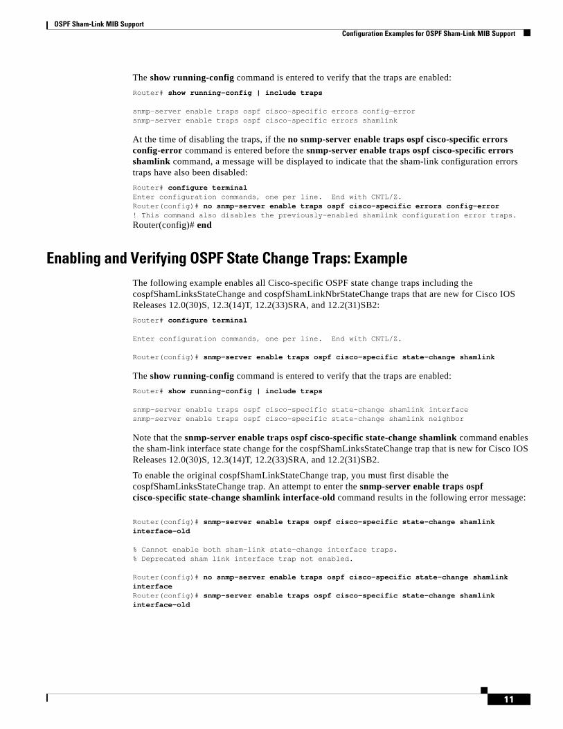
OSPF Sham-Link MIB Support Configuration Examples for OSPF Sham-Link MIB Support
11
The show running-config command is entered to verify that the traps are enabled:
Router# show running-config | include traps
snmp-server enable traps ospf cisco-specific errors config-errorsnmp-server enable traps ospf cisco-specific errors shamlink
At the time of disabling the traps, if the no snmp-server enable traps ospf cisco-specific errors config-error command is entered before the snmp-server enable traps ospf cisco-specific errors shamlink command, a message will be displayed to indicate that the sham-link configuration errors traps have also been disabled:
Router# configure terminalEnter configuration commands, one per line. End with CNTL/Z.Router(config)# no snmp-server enable traps ospf cisco-specific errors config-error! This command also disables the previously-enabled shamlink configuration error traps.
Router(config)# end
Enabling and Verifying OSPF State Change Traps: ExampleThe following example enables all Cisco-specific OSPF state change traps including the cospfShamLinksStateChange and cospfShamLinkNbrStateChange traps that are new for Cisco IOS Releases 12.0(30)S, 12.3(14)T, 12.2(33)SRA, and 12.2(31)SB2:
Router# configure terminal
Enter configuration commands, one per line. End with CNTL/Z.
Router(config)# snmp-server enable traps ospf cisco-specific state-change shamlink
The show running-config command is entered to verify that the traps are enabled:
Router# show running-config | include traps
snmp-server enable traps ospf cisco-specific state-change shamlink interfacesnmp-server enable traps ospf cisco-specific state-change shamlink neighbor
Note that the snmp-server enable traps ospf cisco-specific state-change shamlink command enables the sham-link interface state change for the cospfShamLinksStateChange trap that is new for Cisco IOS Releases 12.0(30)S, 12.3(14)T, 12.2(33)SRA, and 12.2(31)SB2.
To enable the original cospfShamLinkStateChange trap, you must first disable the cospfShamLinksStateChange trap. An attempt to enter the snmp-server enable traps ospf cisco-specific state-change shamlink interface-old command results in the following error message:
Router(config)# snmp-server enable traps ospf cisco-specific state-change shamlink interface-old
% Cannot enable both sham-link state-change interface traps.% Deprecated sham link interface trap not enabled.
Router(config)# no snmp-server enable traps ospf cisco-specific state-change shamlink interfaceRouter(config)# snmp-server enable traps ospf cisco-specific state-change shamlink interface-old
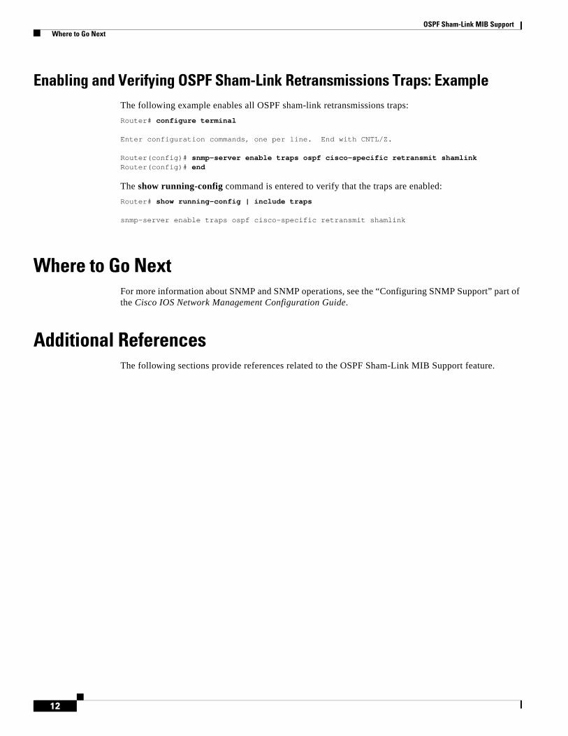
OSPF Sham-Link MIB Support Where to Go Next
12
Enabling and Verifying OSPF Sham-Link Retransmissions Traps: ExampleThe following example enables all OSPF sham-link retransmissions traps:
Router# configure terminal
Enter configuration commands, one per line. End with CNTL/Z.
Router(config)# snmp-server enable traps ospf cisco-specific retransmit shamlinkRouter(config)# end
The show running-config command is entered to verify that the traps are enabled:
Router# show running-config | include traps
snmp-server enable traps ospf cisco-specific retransmit shamlink
Where to Go NextFor more information about SNMP and SNMP operations, see the “Configuring SNMP Support” part of the Cisco IOS Network Management Configuration Guide.
Additional ReferencesThe following sections provide references related to the OSPF Sham-Link MIB Support feature.
OSPF Sham-Link MIB Support Command Reference
13
Related Documents
Standards
MIBs
RFCs
Technical Assistance
Command ReferenceThe following commands are introduced or modified in the feature or features documented in this module. For information about these commands, see the Cisco IOS IP Routing: OSPF Command
Related Topic Document Title
Configuring OSPF sham-links OSPF Sham-Link Support for MPLS VPN
SNMP configuration Cisco IOS Network Management Configuration Guide.
SNMP commands Cisco IOS Network Management Command Reference.
Standard Title
None —
MIB MIBs Link
• CISCO-OSPF-MIB
• CISCO-OSPF-TRAP-MIB
To locate and download MIBs for selected platforms, Cisco IOS releases, and feature sets, use Cisco MIB Locator found at the following URL:
http://www.cisco.com/go/mibs
RFC Title
None —
Description Link
The Cisco Support website provides extensive online resources, including documentation and tools for troubleshooting and resolving technical issues with Cisco products and technologies. Access to most tools on the Cisco Support website requires a Cisco.com user ID and password. If you have a valid service contract but do not have a user ID or password, you can register on Cisco.com.
http://www.cisco.com/techsupport

OSPF Sham-Link MIB Support Feature Information for OSPF Sham-Link MIB Support
14
Reference. For information about all Cisco IOS commands, go to the Command Lookup Tool at http://tools.cisco.com/Support/CLILookup or to the Cisco IOS Master Commands List.
• snmp-server enable traps ospf cisco-specific errors config-error
• snmp-server enable traps ospf cisco-specific errors shamlink
• snmp-server enable traps ospf cisco-specific retransmit
• snmp-server enable traps ospf cisco-specific state-change
Feature Information for OSPF Sham-Link MIB SupportTable 1 lists the release history for this feature.
Not all commands may be available in your Cisco IOS software release. For release information about a specific command, see the command reference documentation.
Use Cisco Feature Navigator to find information about platform support and software image support. Cisco Feature Navigator enables you to determine which Cisco IOS and Catalyst OS software images support a specific software release, feature set, or platform. To access Cisco Feature Navigator, go to http://www.cisco.com/go/cfn. An account on Cisco.com is not required.
Note Table 1 lists only the Cisco IOS software release that introduced support for a given feature in a given Cisco IOS software release train. Unless noted otherwise, subsequent releases of that Cisco IOS software release train also support that feature.
CCDE, CCENT, CCSI, Cisco Eos, Cisco HealthPresence, Cisco IronPort, the Cisco logo, Cisco Nurse Connect, Cisco Pulse, Cisco SensorBase, Cisco StackPower, Cisco StadiumVision, Cisco TelePresence, Cisco Unified Computing System, Cisco WebEx, DCE, Flip Channels, Flip for Good, Flip Mino, Flipshare (Design), Flip Ultra, Flip Video, Flip Video (Design), Instant Broadband, and Welcome to the Human Network are trademarks; Changing the Way We Work, Live, Play, and Learn, Cisco Capital, Cisco Capital (Design), Cisco:Financed (Stylized), Cisco Store, Flip Gift Card, and One Million Acts of Green are service marks; and Access Registrar, Aironet, AllTouch, AsyncOS, Bringing the Meeting To You, Catalyst, CCDA, CCDP, CCIE, CCIP, CCNA, CCNP, CCSP, CCVP, Cisco, the Cisco Certified Internetwork Expert logo, Cisco IOS, Cisco Lumin, Cisco Nexus, Cisco Press, Cisco Systems, Cisco Systems Capital, the Cisco Systems logo, Cisco Unity, Collaboration Without Limitation, Continuum, EtherFast, EtherSwitch, Event Center, Explorer, Follow Me Browsing, GainMaker, iLYNX, IOS, iPhone, IronPort, the IronPort logo, Laser Link, LightStream, Linksys, MeetingPlace, MeetingPlace Chime Sound, MGX, Networkers, Networking Academy, PCNow, PIX, PowerKEY, PowerPanels, PowerTV, PowerTV (Design), PowerVu, Prisma, ProConnect, ROSA, SenderBase, SMARTnet, Spectrum Expert, StackWise, WebEx, and the WebEx logo are registered trademarks of Cisco Systems, Inc. and/or its affiliates in the United States and certain other countries.
All other trademarks mentioned in this document or website are the property of their respective owners. The use of the word partner does not imply a partnership relationship between Cisco and any other company. (0910R)
Table 1 Feature Information for OSPF Sham-Link MIB Support
Feature Name Releases Feature Information
OSPF Sham-Link MIB Support 12.0(30)S12.3(14)T12.2(33)SRA12.2(31)SB212.2(33)SXH
This feature introduces MIB support for the OSPF Sham-Link feature through the addition of new tables and trap MIB objects to the Cisco OSPF MIB (CISCO-OSPF-MIB) and the Cisco OSPF Trap MIB (CISCO-OSPF-TRAP-MIB). New commands have been added to enable Simple Network Management Protocol (SNMP) notifications for the Open Shortest Path First (OSPF) sham-link trap objects. Notifications are provided for errors, state changes, and retransmissions across a sham-link interface..

OSPF Sham-Link MIB Support Feature Information for OSPF Sham-Link MIB Support
15
Any Internet Protocol (IP) addresses used in this document are not intended to be actual addresses. Any examples, command display output, and figures included in the document are shown for illustrative purposes only. Any use of actual IP addresses in illustrative content is unintentional and coincidental.
© 2004–2008 Cisco Systems, Inc. All rights reserved.

OSPF Sham-Link MIB Support Feature Information for OSPF Sham-Link MIB Support
16
Americas Headquarters:Cisco Systems, Inc., 170 West Tasman Drive, San Jose, CA 95134-1706 USA
OSPF Support for Multi-VRF on CE Routers
The OSPF Support for Multi-VRF on CE Routers feature provides the capability of suppressing provider edge (PE) checks that are needed to prevent loops when the PE is performing a mutual redistribution of packets between the OSPF and BGP protocols. When VPN routing and forward (VRF) is used on a router that is not a PE (that is, one that is not running BGP), the checks can be turned off to allow for correct population of the VRF routing table with routes to IP prefixes.
OSPF multi-VRF allows you to split the router into multiple virtual routers, where each router contains its own set of interfaces, routing table, and forwarding table.
Feature Specifications for the OSPF Support for Multi-VRF on CE Routers Feature
Determining Platform Support Through Cisco Feature Navigator
Cisco IOS software is packaged in feature sets that are supported on specific platforms. To get updated information regarding platform support for this feature, access Cisco Feature Navigator. Cisco Feature Navigator dynamically updates the list of supported platforms as new platform support is added for the feature.
Cisco Feature Navigator is a web-based tool that enables you to determine which Cisco IOS software images support a specific set of features and which features are supported in a specific Cisco IOS image. You can search by feature or release. Under the release section, you can compare releases side by side to display both the features unique to each software release and the features in common.
Feature HistoryRelease Modification
12.0(21)ST This feature was introduced.
12.0(22)S This feature was integrated into Cisco IOS Release 12.0(22)S.
12.2(8)B This feature was integrated into Cisco IOS Release 12.2(8)B.
12.2(13)T This feature was integrated into Cisco IOS Release 12.2(13)T.
12.2(14)S This feature was integrated into Cisco IOS Release 12.2(14)S.
Supported Platforms
For information about platforms supported in Cisco IOS Release 12.0(21)ST, 12.0(22)S, 12.2(13)T, and 12.2(14)S, refer to Cisco Feature Navigator. Cisco Feature Navigator does not support Cisco IOS Release 12.2(8)B.
OSPF Support for Multi-VRF on CE Routers Contents
2
Cisco Feature Navigator is updated regularly when major Cisco IOS software releases and technology releases occur. For the most current information, go to the Cisco Feature Navigator home page at the following URL:
http://www.cisco.com/go/fn
Availability of Cisco IOS Software Images
Platform support for particular Cisco IOS software releases is dependent on the availability of the software images for those platforms. Software images for some platforms may be deferred, delayed, or changed without prior notice. For updated information about platform support and availability of software images for each Cisco IOS software release, refer to the online release notes or, if supported, Cisco Feature Navigator.
Contents• Information About OSPF Support for Multi-VRF on CE Routers, page 2
• How to Configure OSPF Support for Multi-VRF on CE Routers, page 2
• Configuration Examples for OSPF Support for Multi-VRF on CE Routers, page 4
• Additional References, page 6
• Command Reference, page 7
• Glossary, page 8
Information About OSPF Support for Multi-VRF on CE RoutersBefore you configure OSPF support for multi-VRF on CE routers, you should understand the following concepts:
• Benefits of OSPF Multi-VRF Support, page 2
Benefits of OSPF Multi-VRF SupportThe OSPF Support for Multi-VRF on CE Routers feature provides the capability of suppressing provider edge (PE) checks that are needed to prevent loops when the PE is performing a mutual redistribution of packets between the OSPF and BGP protocols. When VPN routing and forward (VRF) is used on a router that is not a PE (that is, one that is not running BGP), the checks can be turned off to allow for correct population of the VRF routing table with routes to IP prefixes.
OSPF multi-VRF allows you to split the router into multiple virtual routers, where each router contains its own set of interfaces, routing table, and forwarding table. OSPF multi-VRF gives you the ability to segment parts of your network and configure those segments to perform specific functions, yet still maintain correct routing information.
How to Configure OSPF Support for Multi-VRF on CE RoutersThis section contains the following procedures:
• Configuring the Multi-VRF Capability for OSPF Routing, page 3
OSPF Support for Multi-VRF on CE Routers How to Configure OSPF Support for Multi-VRF on CE Routers
3
• Verifying the OSPF Multi-VRF Configuration, page 4
Configuring the Multi-VRF Capability for OSPF RoutingThis section describes how to configure the multi-VRF for OSPF routing. This task assumes that you have already configured a VRF. For a complete VRF configuration example, see the “Configuring the Multi-VRF Capability Example” section on page 4.
Prerequisites
CEF must be running on the network.
SUMMARY STEPS
1. enable
2. show ip ospf [process-id]
3. configure terminal
4. router ospf process-id [vrf vpn-name]
5. capability vrf-lite
DETAILED STEPS
Command or Action Purpose
Step 1 enable
Example:Router> enable
Enables higher privilege levels, such as privileged EXEC mode.
• Enter your password if prompted.
Step 2 show ip ospf [process-id]
Example:Router> show ip ospf 1
Displays the status of the router. If the display indicates that the router is connected to the VPN backbone, you can use the capability vrf-lite command to decouple the PE router from the VPN backbone.
Step 3 configure terminal
Example:Router# configure terminal
Enters global configuration mode.
Step 4 router ospf process-id [vrf vpn-name]
Example:Router(config)# router ospf 1 vrf grc
Enables OSPF routing and enters router configuration mode.
• The process-id argument identifies the OSPF process.
• Use the vrf keyword and vpn-name argument to identify a VPN.
Step 5 capability vrf-lite
Example:Router(config)# capability vrf-lite
Applies the multi-VRF capability to the OSPF process.
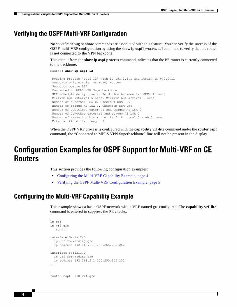
OSPF Support for Multi-VRF on CE Routers Configuration Examples for OSPF Support for Multi-VRF on CE Routers
4
Verifying the OSPF Multi-VRF ConfigurationNo specific debug or show commands are associated with this feature. You can verify the success of the OSPF multi-VRF configuration by using the show ip ospf [process-id] command to verify that the router is not connected to the VPN backbone.
This output from the show ip ospf process command indicates that the PE router is currently connected to the backbone.
Router# show ip ospf 12
Routing Process "ospf 12" with ID 151.1.1.1 and Domain ID 0.0.0.12 Supports only single TOS(TOS0) routes Supports opaque LSA Connected to MPLS VPN Superbackbone SPF schedule delay 5 secs, Hold time between two SPFs 10 secs Minimum LSA interval 5 secs. Minimum LSA arrival 1 secs Number of external LSA 0. Checksum Sum 0x0 Number of opaque AS LSA 0. Checksum Sum 0x0 Number of DCbitless external and opaque AS LSA 0 Number of DoNotAge external and opaque AS LSA 0 Number of areas in this router is 0. 0 normal 0 stub 0 nssa External flood list length 0
When the OSPF VRF process is configured with the capability vrf-lite command under the router ospf command, the “Connected to MPLS VPN Superbackbone” line will not be present in the display.
Configuration Examples for OSPF Support for Multi-VRF on CE Routers
This section provides the following configuration examples:
• Configuring the Multi-VRF Capability Example, page 4
• Verifying the OSPF Multi-VRF Configuration Example, page 5
Configuring the Multi-VRF Capability ExampleThis example shows a basic OSPF network with a VRF named grc configured. The capability vrf-lite command is entered to suppress the PE checks.
!ip cefip vrf grc
rd 1:1
interface Serial2/0ip vrf forwarding grcip address 192.168.1.1 255.255.255.252
!interface Serial3/0
ip vrf forwarding grcip address 192.168.2.1 255.255.255.252
...
!router ospf 9000 vrf grc

OSPF Support for Multi-VRF on CE Routers Configuration Examples for OSPF Support for Multi-VRF on CE Routers
5
log-adjacency-changescapability vrf-literedistribute rip metric 1 subnetsnetwork 192.168.1.0 0.0.0.255 area 0
!router rip
address-family ipv4 vrf grcredistribute ospf 9000 vrf grcnetwork network 192.168.2.0no auto-summaryend
Router# show ip route vrf grc
Routing Table: grcCodes: C - connected, S - static, R - RIP, M - mobile, B - BGP
D - EIGRP, EX - EIGRP external, O - OSPF, IA - OSPF inter area N1 - OSPF NSSA external type 1, N2 - OSPF NSSA external type 2E1 - OSPF external type 1, E2 - OSPF external type 2i - IS-IS, su - IS-IS summary, L1 - IS-IS level-1, L2 - IS-IS level-2ia - IS-IS inter area, * - candidate default, U - per-user static routeo - ODR, P - periodic downloaded static route
Gateway of last resort is not set
O IA 192.168.192.0/24 [110/138] via 192.168.1.13, 00:06:08, Serial2/0[110/138] via 192.168.1.9, 00:06:08, Serial3/0
O IA 192.168.242.0/24 [110/74] via 192.168.1.13, 00:06:08, Serial2/0O IA 192.168.193.0/24 [110/148] via 192.168.1.13, 00:06:08, Serial2/0
[110/148] via 192.168.1.9, 00:06:08, Serial3/0O IA 192.168.128.0/24 [110/74] via 192.168.1.9, 00:06:08, Serial3/0O IA 192.168.129.0/24 [110/84] via 192.168.1.9, 00:06:08, Serial3/0O IA 192.168.130.0/24 [110/84] via 192.168.1.9, 00:06:08, Serial3/0
172.16.0.0/24 is subnetted, 2 subnetsO E2 172.16.9.0 [110/5] via 192.168.1.13, 00:06:08, Serial2/0O E2 172.16.10.0 [110/5] via 192.168.1.13, 00:06:08, Serial2/0O IA 192.168.131.0/24 [110/94] via 192.168.1.9, 00:06:20, Serial3/0
192.168.1.0/30 is subnetted, 4 subnetsC 192.168.1.8 is directly connected, Serial3/0C 192.168.1.12 is directly connected, Serial2/0O 192.168.1.0 [110/128] via 192.168.1.9, 00:06:20, Serial3/0O 192.168.1.4 [110/128] via 192.168.1.13, 00:06:20, Serial2/0
Verifying the OSPF Multi-VRF Configuration ExampleThis example illustrates the output display from the show ip ospf process command after OSPF multi-VRF has been configured on the router.
Router# show ip ospf database external 172.16.0.0 self
OSPF Router with ID (10.0.0.1) (Process ID 100)
Type-5 AS External Link States
LS age: 175Options: (No TOS-capability, DC)LS Type: AS External LinkLink State ID: 172.16.0.0 (External Network Number )Advertising Router: 10.0.0.1LS Seq Number: 80000001Checksum: 0xEA9E
OSPF Support for Multi-VRF on CE Routers Additional References
6
Length: 36Network Mask: /8
Metric Type: 2 (Larger than any link state path)MTID: 0Metric: 20Forward Address: 0.0.0.0External Route Tag: 0
Additional ReferencesFor additional information related to OSPF support for multi-VRF on CE routers, refer to the following references:
Related Documents
Standards
MIBs
To locate and download MIBs for selected platforms, Cisco IOS releases, and feature sets, use Cisco MIB Locator found at the following URL:
http://tools.cisco.com/ITDIT/MIBS/servlet/index
If Cisco MIB Locator does not support the MIB information that you need, you can also obtain a list of supported MIBs and download MIBs from the Cisco MIBs page at the following URL:
http://www.cisco.com/public/sw-center/netmgmt/cmtk/mibs.shtml
Related Topic Document Title
Configuring OSPF Configuring OSPF
Multiprotocol Label Switching (MPLS) MPLS Multi–VRF (VRF Lite) Support
Standards1
1. Not all supported standards are listed.
Title
No new or modified standards are supported by this feature, and support for existing standards has not been modified by this feature.
—
MIBs1
1. Not all supported MIBs are listed.
MIBs Link
No new or modified MIBs are supported by this feature, and support for existing MIBs has not been modified by this feature.
To obtain lists of supported MIBs by platform and Cisco IOS release, and to download MIB modules, go to the Cisco MIB website on Cisco.com at the following URL:
http://www.cisco.com/public/sw-center/netmgmt/cmtk/mibs.shtml
OSPF Support for Multi-VRF on CE Routers Command Reference
7
RFCs
Technical Assistance
Command ReferenceThe following commands are introduced or modified in the feature or features documented in this module. For information about these commands, see the Cisco IOS IP Routing: OSPF Command Reference. For information about all Cisco IOS commands, go to the Command Lookup Tool at http://tools.cisco.com/Support/CLILookup or to the Cisco IOS Master Commands List.
• capability vrf-lite
RFCs1
1. Not all supported RFCs are listed.
Title
No new or modified RFCs are supported by this feature, and support for existing RFCs has not been modified by this feature.
—
Description Link
Technical Assistance Center (TAC) home page, containing 30,000 pages of searchable technical content, including links to products, technologies, solutions, technical tips, tools, and lots more. Registered Cisco.com users can log in from this page to access even more content.
http://www.cisco.com/public/support/tac/home.shtml

OSPF Support for Multi-VRF on CE Routers Glossary
8
GlossaryCE Router—Customer Edge router, an edge router in the C network, defined as a C router which attaches directly to a P router.
C Network—Customer (enterprise or service provider) network.
C Router—Customer router, a router in the C network.
LSA—link-state advertisement. Broadcast packet used by link-state protocols that contains information about neighbors and path costs. LSAs are used by the receiving routers to maintain their routing tables.
PE Router—Provider Edge router, an edge router in the P network, defined as a P router which attaches directly to a C router.
P Network—MPLS-capable service provider core network. P routers perform MPLS.
P Router—Provider router, a router in the P network.
SPF—shortest path first. A routing algorithm that iterates on length of path to determine a shortest-path spanning tree.
VPN—Virtual Private Network. Enables IP traffic to travel securely over a public TCP/IP network by encrypting all traffic from one network to another.
VRF—VPN Routing and Forwarding.
CCDE, CCENT, CCSI, Cisco Eos, Cisco HealthPresence, Cisco IronPort, the Cisco logo, Cisco Nurse Connect, Cisco Pulse, Cisco SensorBase, Cisco StackPower, Cisco StadiumVision, Cisco TelePresence, Cisco Unified Computing System, Cisco WebEx, DCE, Flip Channels, Flip for Good, Flip Mino, Flipshare (Design), Flip Ultra, Flip Video, Flip Video (Design), Instant Broadband, and Welcome to the Human Network are trademarks; Changing the Way We Work, Live, Play, and Learn, Cisco Capital, Cisco Capital (Design), Cisco:Financed (Stylized), Cisco Store, Flip Gift Card, and One Million Acts of Green are service marks; and Access Registrar, Aironet, AllTouch, AsyncOS, Bringing the Meeting To You, Catalyst, CCDA, CCDP, CCIE, CCIP, CCNA, CCNP, CCSP, CCVP, Cisco, the Cisco Certified Internetwork Expert logo, Cisco IOS, Cisco Lumin, Cisco Nexus, Cisco Press, Cisco Systems, Cisco Systems Capital, the Cisco Systems logo, Cisco Unity, Collaboration Without Limitation, Continuum, EtherFast, EtherSwitch, Event Center, Explorer, Follow Me Browsing, GainMaker, iLYNX, IOS, iPhone, IronPort, the IronPort logo, Laser Link, LightStream, Linksys, MeetingPlace, MeetingPlace Chime Sound, MGX, Networkers, Networking Academy, PCNow, PIX, PowerKEY, PowerPanels, PowerTV, PowerTV (Design), PowerVu, Prisma, ProConnect, ROSA, SenderBase, SMARTnet, Spectrum Expert, StackWise, WebEx, and the WebEx logo are registered trademarks of Cisco Systems, Inc. and/or its affiliates in the United States and certain other countries.
All other trademarks mentioned in this document or website are the property of their respective owners. The use of the word partner does not imply a partnership relationship between Cisco and any other company. (0910R)
Any Internet Protocol (IP) addresses used in this document are not intended to be actual addresses. Any examples, command display output, and figures included in the document are shown for illustrative purposes only. Any use of actual IP addresses in illustrative content is unintentional and coincidental.
© 2008 Cisco Systems, Inc. All rights reserved.

Americas Headquarters:Cisco Systems, Inc., 170 West Tasman Drive, San Jose, CA 95134-1706 USA
OSPF Forwarding Address Suppression in Translated Type-5 LSAs
The OSPF Forwarding Address Suppression in Translated Type-5 LSAs feature causes a not-so-stubby area (NSSA) area border router (ABR) to translate Type-7 link state advertisements (LSAs) to Type-5 LSAs, but use the address 0.0.0.0 for the forwarding address instead of that specified in the Type-7 LSA. This feature causes routers that are configured not to advertise forwarding addresses into the backbone to direct forwarded traffic to the translating NSSA ABRs.
History for the OSPF Forwarding Address Suppression in Translated Type-5 LSAs Feature
Finding Support Information for Platforms and Cisco IOS Software Images
Use Cisco Feature Navigator to find information about platform support and Cisco IOS software image support. Access Cisco Feature Navigator at http://www.cisco.com/go/fn. You must have an account on Cisco.com. If you do not have an account or have forgotten your username or password, click Cancel at the login dialog box and follow the instructions that appear.
Feature HistoryRelease Modification
12.2(15)T This feature was introduced.
12.2(18)S This feature was integrated into Cisco IOS Release 12.2(18)S.
12.2(27)SBC This feature was integrated into Cisco IOS Release 12.2(27)SBC.
OSPF Forwarding Address Suppression in Translated Type-5 LSAs Contents
2
Contents• Prerequisites for OSPF Forwarding Address Suppression in Translated Type-5 LSAs, page 2
• Information About OSPF Forwarding Address Suppression in Translated Type-5 LSAs, page 2
• How to Suppress OSPF Forwarding Address in Translated Type-5 LSAs, page 3
• Configuration Examples for OSPF Forwarding Address Suppression in Translated Type-5 LSAs, page 5
• Additional References, page 5
• Command Reference, page 7
Prerequisites for OSPF Forwarding Address Suppression in Translated Type-5 LSAs
This document presumes you have OSPF configured on the networking device; it does not document other steps to configure OSPF.
Information About OSPF Forwarding Address Suppression in Translated Type-5 LSAs
Before you configure the OSPF Forwarding Address Suppression in Translated Type-5 LSAs feature, you should understand the following concepts:
• Benefits of OSPF Forwarding Address Suppression in Translated Type-5 LSAs, page 2
• When to Suppress OSPF Forwarding Address in Translated Type-5 LSAs, page 2
Benefits of OSPF Forwarding Address Suppression in Translated Type-5 LSAsThe OSPF Forwarding Address Suppression in Translated Type-5 LSAs feature causes an NSSA ABR to translate Type-7 LSAs to Type-5 LSAs, but use the 0.0.0.0 as the forwarding address instead of that specified in the Type-7 LSA. This feature causes routers that are configured not to advertise forwarding addresses into the backbone to direct forwarded traffic to the translating NSSA ASBRs.
When to Suppress OSPF Forwarding Address in Translated Type-5 LSAsIn Figure 1, it would be advantageous to filter Area 2 addresses from Area 0 to minimize the number of routes introduced into the backbone (Area 0). However, using the area range command to consolidate and summarize routes at the area boundary—filtering the Area 2 addresses—will not work because the Area 2 addresses include forwarding addresses for Type-7 LSAs that are generated by the ASBR. If these Type-7 LSA forwarding addresses have been filtered out of Area 0, the backbone routers cannot reach the prefixes advertised in the translated Type-5 LSAs (autonomous system external LSAs).
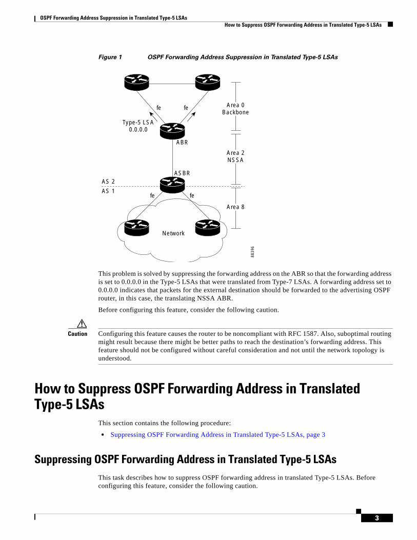
OSPF Forwarding Address Suppression in Translated Type-5 LSAs How to Suppress OSPF Forwarding Address in Translated Type-5 LSAs
3
Figure 1 OSPF Forwarding Address Suppression in Translated Type-5 LSAs
This problem is solved by suppressing the forwarding address on the ABR so that the forwarding address is set to 0.0.0.0 in the Type-5 LSAs that were translated from Type-7 LSAs. A forwarding address set to 0.0.0.0 indicates that packets for the external destination should be forwarded to the advertising OSPF router, in this case, the translating NSSA ABR.
Before configuring this feature, consider the following caution.
Caution Configuring this feature causes the router to be noncompliant with RFC 1587. Also, suboptimal routing might result because there might be better paths to reach the destination’s forwarding address. This feature should not be configured without careful consideration and not until the network topology is understood.
How to Suppress OSPF Forwarding Address in Translated Type-5 LSAs
This section contains the following procedure:
• Suppressing OSPF Forwarding Address in Translated Type-5 LSAs, page 3
Suppressing OSPF Forwarding Address in Translated Type-5 LSAsThis task describes how to suppress OSPF forwarding address in translated Type-5 LSAs. Before configuring this feature, consider the following caution.
8839
6
AS 2
AS 1fe fe
fe
Type-5 LSA0.0.0.0
fe
ABR
ASBR
Network
Area 0Backbone
Area 2NSSA
Area 8
OSPF Forwarding Address Suppression in Translated Type-5 LSAs How to Suppress OSPF Forwarding Address in Translated Type-5 LSAs
4
Caution Configuring this feature causes the router to be noncompliant with RFC 1587. Also, suboptimal routing might result because there might be better paths to reach the destination’s forwarding address. This feature should not be configured without careful consideration and not until the network topology is understood.
SUMMARY STEPS
1. enable
2. configure terminal
3. router ospf process-id
4. area area-id nssa translate type7 suppress-fa
5. end
DETAILED STEPS
Command or Action Purpose
Step 1 enable
Example:Router> enable
Enables higher privilege levels, such as privileged EXEC mode.
• Enter your password if prompted.
Step 2 configure terminal
Example:Router# configure terminal
Enters global configuration mode.
Step 3 router ospf process-id
Example:Router(config)# router ospf 1
Enables OSPF routing and enters router configuration mode.
• The process-id argument identifies the OSPF process.
Step 4 area area-id nssa translate type7 suppress-fa
Example:Router(config-router)# area 10 nssa translate type7 suppress-fa
Configures an area as a not-so-stubby-area (NSSA) and suppresses the forwarding address in translated Type-7 LSAs.
Step 5 end
Example:Router(config-router)# end
Exits configuration mode and returns to privileged EXEC mode.

OSPF Forwarding Address Suppression in Translated Type-5 LSAs Configuration Examples for OSPF Forwarding Address Suppression in Translated Type-5 LSAs
5
Configuration Examples for OSPF Forwarding Address Suppression in Translated Type-5 LSAs
This section provides the following configuration example:
• Suppressing OSPF Forwarding Address in Translated Type-5 LSAs: Example, page 5
Suppressing OSPF Forwarding Address in Translated Type-5 LSAs: ExampleThis example suppresses the forwarding address in translated Type-5 LSAs:
interface ethernet 0ip address 10.93.1.1 255.255.255.0ip ospf cost 1
!interface ethernet 1ip address 10.94.1.1 255.255.255.0
!router ospf 1network 10.93.0.0 0.0.255.255 area 0.0.0.0network 10.94.0.0 0.0.255.255 area 10area 10 nssa translate type7 suppress-fa
Additional ReferencesFor additional information related to OSPF, see the following sections:
• Related Documents, page 6
• Standards, page 6
• MIBs, page 6
• RFCs, page 6
• Technical Assistance, page 6
OSPF Forwarding Address Suppression in Translated Type-5 LSAs Additional References
6
Related Documents
Standards
MIBs
RFCs
Technical Assistance
Related Topic Document Title
OSPF commands Cisco IOS IP Routing: OSPF Command Reference
Standards Title
No new or modified standards are supported by this feature, and support for existing standards has not been modified by this feature.
—
MIBs MIBs Link
No new or modified MIBs are supported by this feature, and support for existing MIBs has not been modified by this feature.
To locate and download MIBs for selected platforms, Cisco IOS releases, and feature sets, use Cisco MIB Locator found at the following URL:
http://www.cisco.com/go/mibs
RFCs Title
Configuring the OSPF Forwarding Address Suppression in Translated Type-5 LSAs feature causes the router to be noncompliant with RFC 1587.
The OSPF NSSA Option
Description Link
The Cisco Technical Support website contains thousands of pages of searchable technical content, including links to products, technologies, solutions, technical tips, and tools. Registered Cisco.com users can log in from this page to access even more content.
http://www.cisco.com/techsupport
OSPF Forwarding Address Suppression in Translated Type-5 LSAs Command Reference
7
Command ReferenceThe following commands are introduced or modified in the feature or features documented in this module. For information about these commands, see the Cisco IOS IP Routing: OSPF Command Reference. For information about all Cisco IOS commands, go to the Command Lookup Tool at http://tools.cisco.com/Support/CLILookup or to the Cisco IOS Master Commands List.
• area nssa translate
• show ip ospf
CCDE, CCENT, CCSI, Cisco Eos, Cisco HealthPresence, Cisco IronPort, the Cisco logo, Cisco Nurse Connect, Cisco Pulse, Cisco SensorBase, Cisco StackPower, Cisco StadiumVision, Cisco TelePresence, Cisco Unified Computing System, Cisco WebEx, DCE, Flip Channels, Flip for Good, Flip Mino, Flipshare (Design), Flip Ultra, Flip Video, Flip Video (Design), Instant Broadband, and Welcome to the Human Network are trademarks; Changing the Way We Work, Live, Play, and Learn, Cisco Capital, Cisco Capital (Design), Cisco:Financed (Stylized), Cisco Store, Flip Gift Card, and One Million Acts of Green are service marks; and Access Registrar, Aironet, AllTouch, AsyncOS, Bringing the Meeting To You, Catalyst, CCDA, CCDP, CCIE, CCIP, CCNA, CCNP, CCSP, CCVP, Cisco, the Cisco Certified Internetwork Expert logo, Cisco IOS, Cisco Lumin, Cisco Nexus, Cisco Press, Cisco Systems, Cisco Systems Capital, the Cisco Systems logo, Cisco Unity, Collaboration Without Limitation, Continuum, EtherFast, EtherSwitch, Event Center, Explorer, Follow Me Browsing, GainMaker, iLYNX, IOS, iPhone, IronPort, the IronPort logo, Laser Link, LightStream, Linksys, MeetingPlace, MeetingPlace Chime Sound, MGX, Networkers, Networking Academy, PCNow, PIX, PowerKEY, PowerPanels, PowerTV, PowerTV (Design), PowerVu, Prisma, ProConnect, ROSA, SenderBase, SMARTnet, Spectrum Expert, StackWise, WebEx, and the WebEx logo are registered trademarks of Cisco Systems, Inc. and/or its affiliates in the United States and certain other countries.
All other trademarks mentioned in this document or website are the property of their respective owners. The use of the word partner does not imply a partnership relationship between Cisco and any other company. (0910R)
Any Internet Protocol (IP) addresses used in this document are not intended to be actual addresses. Any examples, command display output, and figures included in the document are shown for illustrative purposes only. Any use of actual IP addresses in illustrative content is unintentional and coincidental.
© 2007–2008 Cisco Systems, Inc. All rights reserved.

OSPF Forwarding Address Suppression in Translated Type-5 LSAs Command Reference
8
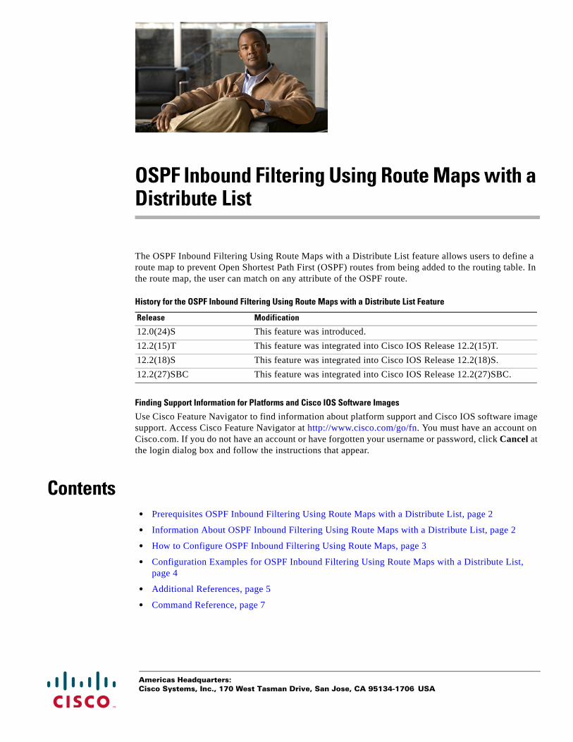
Americas Headquarters:Cisco Systems, Inc., 170 West Tasman Drive, San Jose, CA 95134-1706 USA
OSPF Inbound Filtering Using Route Maps with a Distribute List
The OSPF Inbound Filtering Using Route Maps with a Distribute List feature allows users to define a route map to prevent Open Shortest Path First (OSPF) routes from being added to the routing table. In the route map, the user can match on any attribute of the OSPF route.
History for the OSPF Inbound Filtering Using Route Maps with a Distribute List Feature
Finding Support Information for Platforms and Cisco IOS Software Images
Use Cisco Feature Navigator to find information about platform support and Cisco IOS software image support. Access Cisco Feature Navigator at http://www.cisco.com/go/fn. You must have an account on Cisco.com. If you do not have an account or have forgotten your username or password, click Cancel at the login dialog box and follow the instructions that appear.
Contents• Prerequisites OSPF Inbound Filtering Using Route Maps with a Distribute List, page 2
• Information About OSPF Inbound Filtering Using Route Maps with a Distribute List, page 2
• How to Configure OSPF Inbound Filtering Using Route Maps, page 3
• Configuration Examples for OSPF Inbound Filtering Using Route Maps with a Distribute List, page 4
• Additional References, page 5
• Command Reference, page 7
Release Modification
12.0(24)S This feature was introduced.
12.2(15)T This feature was integrated into Cisco IOS Release 12.2(15)T.
12.2(18)S This feature was integrated into Cisco IOS Release 12.2(18)S.
12.2(27)SBC This feature was integrated into Cisco IOS Release 12.2(27)SBC.

OSPF Inbound Filtering Using Route Maps with a Distribute List Prerequisites OSPF Inbound Filtering Using Route Maps with a Distribute List
2
Prerequisites OSPF Inbound Filtering Using Route Maps with a Distribute List
It is presumed that you have OSPF configured in your network.
Information About OSPF Inbound Filtering Using Route Maps with a Distribute List
Before you configure filtering based on an OSPF route map, you should understand the concept described in this section.
• Benefits of OSPF Route-Map-Based-Filtering, page 2
Benefits of OSPF Route-Map-Based-FilteringUsers can define a route map to prevent OSPF routes from being added to the routing table. This filtering happens at the moment when OSPF is installing the route in the routing table. This feature has no effect on LSA flooding. In the route map, the user can match on any attribute of the OSPF route. That is, the route map could be based on the following match options:
• match interface
• match ip address
• match ip next-hop
• match ip route-source
• match metric
• match route-type
• match tag
This feature can be useful during redistribution if the user tags prefixes when they get redistributed on ASBRs and later uses the tag to filter the prefixes from being installed in the routing table on other routers.
Filtering Based on Route Tag
Users can assign tags to external routes when they are redistributed to OSPF. Then the user can deny or permit those routes in the OSPF domain by identifying that tag in the route-map and distribute-list in commands.
Filtering Based on Route Type
In OSPF, the external routes could be Type 1 or Type 2. Users can create route maps to match either Type 1 or Type 2 and then use the distribute-list in command to filter certain prefixes. Also, route maps can identify internal routes (interarea and intra-area) and then those routes can be filtered.
Filtering Based on Route Source
When a match is done on the route source, the route source represents the OSPF Router ID of the LSA originator of the LSA in which the prefix is advertised.

OSPF Inbound Filtering Using Route Maps with a Distribute List How to Configure OSPF Inbound Filtering Using Route Maps
3
Filtering Based on Interface
When a match is done on the interface, the interface represents the outgoing interface for the route that OSPF is trying to install in the routing table.
Filtering Based on Next-Hop
When a match is done on the next hop, the next hop represents the next hop for the route that OSPF is trying to install in the routing table.
How to Configure OSPF Inbound Filtering Using Route MapsThis section describes enabling OSPF filtering based on a route map.
• Configuring OSPF Route- Map-Based Filtering, page 3
Configuring OSPF Route-Map-Based FilteringThis section describes how to configure OSPF route map-based filtering. Step 4 is simply an example of a route map; other match commands could be used.
SUMMARY STEPS
1. enable
2. configure terminal
3. route-map map-tag [permit | deny] [sequence-number]
4. match tag tag-name
or other match commands.
5. Repeat Steps 3 and 4 with other route-map and match commands if you choose.
6. exit
7. router ospf process-id
8. distribute-list route-map map-tag in
9. end
DETAILED STEPS
Command or Action Purpose
Step 1 enable
Example:Router> enable
Enables privileged EXEC mode.
• Enter your password if prompted.
Step 2 configure terminal
Example:Router# configure terminal
Enters global configuration mode.
OSPF Inbound Filtering Using Route Maps with a Distribute List Configuration Examples for OSPF Inbound Filtering Using Route Maps with a Distribute List
4
Configuration Examples for OSPF Inbound Filtering Using Route Maps with a Distribute List
This section contains an example of filtering based on an OSPF route map.
• OSPF Route-Map-Based Filtering: Example, page 5
Step 3 route-map map-tag [permit | deny] [sequence-number]
Example:Router(config)# route-map tag-filter deny 10
Defines a route map to control filtering.
Step 4 match tag tag-name
or other match command(s)
Example:Router(config-router)# match tag 777
Matches routes with a specified name, to be used as the route map is referenced.
• At least one match command is required, but it need not be this match command. This is just an example.
• The list of match commands available to be used in this type of route map appears on the distribute-list in command reference page.
• This type of route map will have no set commands.
Step 5 Repeat Steps 3 and 4 with other route-map and match commands if you choose.
Optional.
Step 6 exit
Example:Router(config-router)# exit
Exits router configuration mode.
Step 7 router ospf process-id
Example:Router(config)# router ospf 1
Configures an OSPF routing process.
Step 8 distribute-list route-map map-tag in
Example:Router(config-router)# distribute-list route-map tag-filter in
Enables filtering based on an OSPF route map.
Step 9 end
Example:Router(config-router)# end
Exits router configuration mode.
Command or Action Purpose

OSPF Inbound Filtering Using Route Maps with a Distribute List Additional References
5
OSPF Route-Map-Based Filtering: ExampleIn this example, OSPF external LSAs have a tag. The value of the tag is examined before the prefix is installed in the routing table. All OSPF external prefixes that have the tag value of 777 are filtered (prevented from being installed in the routing table). The permit statement with sequence number 20 has no match conditions, and there are no other route-map statements after sequence number 20, so all other conditions are permitted.
route-map tag-filter deny 10match tag 777
route-map tag-filter permit 20!router ospf 1router-id 10.0.0.2log-adjacency-changesnetwork 172.16.2.1 0.0.0.255 area 0distribute-list route-map tag-filter in
Additional ReferencesThe following sections provide references related to configuring the OSPF Inbound Filtering Using Route Maps with a Distribute List feature.
Related Documents
Related Topic Document Title
OSPF commands Cisco IOS IP Routing: OSPF Command Reference
OSPF Inbound Filtering Using Route Maps with a Distribute List Additional References
6
Standards
MIBs
RFCs
Technical Assistance
Standards Title
No new or modified standards are supported by this feature, and support for existing standards has not been modified by this feature.
—
MIBs MIBs Link
None To locate and download MIBs for selected platforms, Cisco IOS releases, and feature sets, use Cisco MIB Locator found at the following URL:
http://www.cisco.com/go/mibs
RFCs Title
No new or modified RFCs are supported by this feature, and support for existing RFCs has not been modified by this feature.
—
Description Link
The Cisco Technical Support website contains thousands of pages of searchable technical content, including links to products, technologies, solutions, technical tips, and tools. Registered Cisco.com users can log in from this page to access even more content.
http://www.cisco.com/techsupport
OSPF Inbound Filtering Using Route Maps with a Distribute List Command Reference
7
Command ReferenceThe following commands are introduced or modified in the feature or features documented in this module. For information about these commands, see the Cisco IOS IP Routing: OSPF Command Reference. For information about all Cisco IOS commands, go to the Command Lookup Tool at http://tools.cisco.com/Support/CLILookup or to the Cisco IOS Master Commands List.
• distribute-list in (IP)
CCDE, CCENT, CCSI, Cisco Eos, Cisco HealthPresence, Cisco IronPort, the Cisco logo, Cisco Nurse Connect, Cisco Pulse, Cisco SensorBase, Cisco StackPower, Cisco StadiumVision, Cisco TelePresence, Cisco Unified Computing System, Cisco WebEx, DCE, Flip Channels, Flip for Good, Flip Mino, Flipshare (Design), Flip Ultra, Flip Video, Flip Video (Design), Instant Broadband, and Welcome to the Human Network are trademarks; Changing the Way We Work, Live, Play, and Learn, Cisco Capital, Cisco Capital (Design), Cisco:Financed (Stylized), Cisco Store, Flip Gift Card, and One Million Acts of Green are service marks; and Access Registrar, Aironet, AllTouch, AsyncOS, Bringing the Meeting To You, Catalyst, CCDA, CCDP, CCIE, CCIP, CCNA, CCNP, CCSP, CCVP, Cisco, the Cisco Certified Internetwork Expert logo, Cisco IOS, Cisco Lumin, Cisco Nexus, Cisco Press, Cisco Systems, Cisco Systems Capital, the Cisco Systems logo, Cisco Unity, Collaboration Without Limitation, Continuum, EtherFast, EtherSwitch, Event Center, Explorer, Follow Me Browsing, GainMaker, iLYNX, IOS, iPhone, IronPort, the IronPort logo, Laser Link, LightStream, Linksys, MeetingPlace, MeetingPlace Chime Sound, MGX, Networkers, Networking Academy, PCNow, PIX, PowerKEY, PowerPanels, PowerTV, PowerTV (Design), PowerVu, Prisma, ProConnect, ROSA, SenderBase, SMARTnet, Spectrum Expert, StackWise, WebEx, and the WebEx logo are registered trademarks of Cisco Systems, Inc. and/or its affiliates in the United States and certain other countries.
All other trademarks mentioned in this document or website are the property of their respective owners. The use of the word partner does not imply a partnership relationship between Cisco and any other company. (0910R)
Any Internet Protocol (IP) addresses used in this document are not intended to be actual addresses. Any examples, command display output, and figures included in the document are shown for illustrative purposes only. Any use of actual IP addresses in illustrative content is unintentional and coincidental.
© 2008 Cisco Systems, Inc. All rights reserved.

OSPF Inbound Filtering Using Route Maps with a Distribute List Command Reference
8

Americas Headquarters:Cisco Systems, Inc., 170 West Tasman Drive, San Jose, CA 95134-1706 USA
OSPF Shortest Path First Throttling
The OSPF Shortest Path First Throttling feature makes it possible to configure SPF scheduling in millisecond intervals and to potentially delay shortest path first (SPF) calculations during network instability. SPF is scheduled to calculate the Shortest Path Tree (SPT) when there is a change in topology. One SPF run may include multiple topology change events.
The interval at which the SPF calculations occur is chosen dynamically and is based on the frequency of topology changes in the network. The chosen interval is within the boundary of the user-specified value ranges. If network topology is unstable, SPF throttling calculates SPF scheduling intervals to be longer until topology becomes stable.
Feature Specifications for OSPF Shortest Path First Throttling
Finding Support Information for Platforms and Cisco IOS Software Images
Use Cisco Feature Navigator to find information about platform support and Cisco IOS software image support. Access Cisco Feature Navigator at http://www.cisco.com/go/fn. You must have an account on Cisco.com. If you do not have an account or have forgotten your username or password, click Cancel at the login dialog box and follow the instructions that appear.
Contents• Information About OSPF SPF Throttling, page 2
• How to Configure OSPF SPF Throttling, page 3
• Configuration Examples for OSPF SPF Throttling, page 5
• Additional References, page 6
• Command Reference, page 9
Feature History
Release Modification
12.2(14)S This feature was introduced.
12.0(23)S This feature was integrated into Cisco Release 12.0(23)S.
12.2(15)T This feature was integrated into Cisco IOS Release 12.2(15)T.

OSPF Shortest Path First Throttling Information About OSPF SPF Throttling
2
Information About OSPF SPF ThrottlingTo use SPF throttling, you should understand the following concepts:
• Shortest Path First Calculations, page 2
Shortest Path First CalculationsSPF calculations occur at the interval set by the timers throttle spf command. The wait interval indicates the amount of time to wait until the next SPF calculation occurs. Each wait interval after that calculation is twice as long as the previous one until the wait interval reaches the maximum wait time specified.
The SPF timing can be better explained using an example. In this example the start interval is set at 5 milliseconds (ms), the wait interval at 1000 milliseconds, and the maximum wait time is set at 90,000 milliseconds.
timers throttle spf 5 1000 90000
Figure 1 shows the intervals at which the SPF calculations occur so long as at least one topology change event is received in a given wait interval.
Figure 1 SPF Calculation Intervals Set by the timers throttle spf Command
Notice that the wait interval between SPF calculations doubles when at least one topology change event is received during the previous wait interval. Once the maximum wait time is reached, the wait interval remains the same until the topology stabilizes and no event is received in that interval.
If the first topology change event is received after the current wait interval, the SPF calculation is delayed by the amount of time specified as the start interval. The subsequent wait intervals continue to follow the dynamic pattern.
If the first topology change event occurs after the maximum wait interval begins, the SPF calculation is again scheduled at the start interval and subsequent wait intervals are reset according the parameters specified in the timers throttle spf command. Notice in Figure 2 that a topology change event was received after the start of the maximum wait time interval and that the SPF intervals have been reset.
Figure 2 Timer Intervals Reset after Topology Change Event
8827
8
5 ms1000 ms
2000 ms4000 ms
8000 ms16000 ms
32000 ms64000 ms
90000 ms
8827
9
64000 ms90000 ms
Topology change event
SPF scheduled atstart interval
5 ms1000 ms
2000 ms4000 ms
8000 ms16000 ms
90000 ms

OSPF Shortest Path First Throttling How to Configure OSPF SPF Throttling
3
How to Configure OSPF SPF ThrottlingPerform the following tasks to configure OSPF SPF throttling:
• Configuring OSPF SPF Throttling, page 3 (required)
• Verifying SPF Throttle Values, page 4 (optional)
Configuring OSPF SPF Throttling
SUMMARY STEPS
1. enable
2. configure terminal
3. interface type slot/port
4. ip address ip-address mask [secondary]
5. exit
6. router ospf process-id
7. network network-number [mask | prefix-length]
8. timers throttle spf spf-start spf-hold spf-max-wait
9. end
DETAILED STEPS
Command or Action Purpose
Step 1 enable
Example:Router> enable
Enables higher privilege levels, such as privileged EXEC mode.
Enter your password if prompted.
Step 2 configure terminal
Example:Router# configure terminal
Enters global configuration mode.
Step 3 interface type slot/port
Example:Router(config)# interface ethernet 1/1/1
Enters interface configuration mode for the interface specified.
Step 4 ip address ip-address mask [secondary]
Example:Router(config-if)# ip address 192.168.0.2 255.255.255.0
Sets a primary or secondary IP address for an interface.

OSPF Shortest Path First Throttling How to Configure OSPF SPF Throttling
4
Verifying SPF Throttle ValuesTo verify SPF throttle timer values, use the show ip ospf command. The values are displayed in the lines that begin, “Initial SPF schedule delay...,” “Minimum hold time between two consecutive SPFs...,” and “Maximum wait time between two consecutive SPFs....”
Router# show ip ospf
Routing Process "ospf 1" with ID 10.10.10.2 and Domain ID 0.0.0.1 Supports only single TOS(TOS0) routes Supports opaque LSA It is an autonomous system boundary router Redistributing External Routes from, static, includes subnets in redistributionInitial SPF schedule delay 5 msecs Minimum hold time between two consecutive SPFs 1000 msecs Maximum wait time between two consecutive SPFs 90000 msecs Minimum LSA interval 5 secs. Minimum LSA arrival 1 secs LSA group pacing timer 240 secs Interface flood pacing timer 33 msecs Retransmission pacing timer 66 msecs Number of external LSA 4. Checksum Sum 0x17445 Number of opaque AS LSA 0. Checksum Sum 0x0 Number of DCbitless external and opaque AS LSA 0 Number of DoNotAge external and opaque AS LSA 0 Number of areas in this router is 1. 1 normal 0 stub 0 nssa External flood list length 0 Area BACKBONE(0)
Step 5 exit
Example:router# exit
Exits interface configuration mode.
Step 6 router ospf process-id
Example:Router(config)# router ospf 1
Configures an OSPF routing process.
Step 7 network network-number [mask | prefix-length]
Example:Router(config-router)# network 192.168.0.0 0.0.255.255 area 0
Configures the subnet number and mask for a Dynamic Host Configuration Protocol (DHCP) address pool on a Cisco IOS DHCP Server.
Step 8 timers throttle spf spf-start spf-hold spf-max-wait
Example:Router(config-router)# timers throttle spf 10 4800 90000
Sets OSPF throttling timers.
Step 9 end
Example:Router(config-router)# end
Exits configuration mode.
Command or Action Purpose
OSPF Shortest Path First Throttling Configuration Examples for OSPF SPF Throttling
5
Number of interfaces in this area is 2 Area has no authentication SPF algorithm last executed 19:11:15.140 ago SPF algorithm executed 28 times Area ranges are Number of LSA 4. Checksum Sum 0x2C1D4 Number of opaque link LSA 0. Checksum Sum 0x0 Number of DCbitless LSA 0 Number of indication LSA 0 Number of DoNotAge LSA 0 Flood list length 0
Table 1 describes the show ip ospf display fields and their descriptions.
Configuration Examples for OSPF SPF ThrottlingThis section contains the following examples:
• Throttle Timers Example, page 5
Throttle Timers ExampleThis example shows a router configured with the start, hold, and maximum interval values for the timers throttle spf command set at 5, 1,000, and 90,000 milliseconds, respectively.
router ospf 1
Table 1 show ip ospf Field Descriptions
Field Description
Routing process “ospf 201” with ID 192.42.110.200
Process ID and OSPF router ID.
Supports ... Number of types of service supported (Type 0 only).
It is ... Possible types are internal, area border, or autonomous system boundary.
Summary Link update interval Specifies summary update interval in hours:minutes:seconds, and time until next update.
External Link update interval Specifies external update interval in hours:minutes:seconds, and time until next update.
Redistributing External Routes from Lists of redistributed routes, by protocol.
SPF calculations Lists start, hold, and maximum wait interval values in milliseconds.
Number of areas Number of areas in router, area addresses, and so on.
SPF algorithm last executed Shows the last time an SPF calculation was performed in response to topology change event records.
Link State Update Interval Specifies router and network link-state update interval in hours:minutes:seconds, and time until next update.
Link State Age Interval Specifies max-aged update deletion interval, and time until next database cleanup, in hours:minutes:seconds.

OSPF Shortest Path First Throttling Additional References
6
router-id 10.10.10.2 log-adjacency-changes timers throttle spf 5 1000 90000 redistribute static subnets network 21.21.21.0 0.0.0.255 area 0 network 22.22.22.0 0.0.0.255 area 00
Additional ReferencesFor additional information related to OSPF, refer to the following references:
• Related Documents, page 7
• Standards, page 7
• MIBs, page 7
• RFCs, page 7
• Technical Assistance, page 8

OSPF Shortest Path First Throttling Additional References
7
Related Documents
Standards
MIBs
RFCs
Related Topic Document Title
OSPF commands Cisco IOS IP Routing: OSPF Command Reference
OSPF configuration tasks “Configuring OSPF ” module in the Cisco IOS IP Routing Protocols Configuration Guide
Standards Title
No new or modified RFCs are supported by this feature, and support for existing RFCs has not been modified by this feature.
MIBs MIBs Link
No new or modified MIBs are supported by this feature, and support for existing MIBs has not been modified by this feature.
To locate and download MIBs for selected platforms, Cisco IOS releases, and feature sets, use Cisco MIB Locator found at the following URL:
http://www.cisco.com/go/mibs
RFCs Title
No new or modified standards are supported by this feature, and support for existing standards has not been modified by this feature.
OSPF Shortest Path First Throttling Additional References
8
Technical Assistance
Description Link
The Cisco Support website provides extensive online resources, including documentation and tools for troubleshooting and resolving technical issues with Cisco products and technologies.
To receive security and technical information about your products, you can subscribe to various services, such as the Product Alert Tool (accessed from Field Notices), the Cisco Technical Services Newsletter, and Really Simple Syndication (RSS) Feeds.
Access to most tools on the Cisco Support website requires a Cisco.com user ID and password.
http://www.cisco.com/techsupport

OSPF Shortest Path First Throttling Command Reference
9
Command ReferenceThe following commands are introduced or modified in the feature or features documented in this module. For information about these commands, see the Cisco IOS IP Routing: OSPF Command Reference. For information about all Cisco IOS commands, go to the Command Lookup Tool at http://tools.cisco.com/Support/CLILookup or to the Cisco IOS Master Commands List.
• timers throttle spf
• timer spf-interval
CCDE, CCENT, CCSI, Cisco Eos, Cisco HealthPresence, Cisco IronPort, the Cisco logo, Cisco Nurse Connect, Cisco Pulse, Cisco SensorBase, Cisco StackPower, Cisco StadiumVision, Cisco TelePresence, Cisco Unified Computing System, Cisco WebEx, DCE, Flip Channels, Flip for Good, Flip Mino, Flipshare (Design), Flip Ultra, Flip Video, Flip Video (Design), Instant Broadband, and Welcome to the Human Network are trademarks; Changing the Way We Work, Live, Play, and Learn, Cisco Capital, Cisco Capital (Design), Cisco:Financed (Stylized), Cisco Store, Flip Gift Card, and One Million Acts of Green are service marks; and Access Registrar, Aironet, AllTouch, AsyncOS, Bringing the Meeting To You, Catalyst, CCDA, CCDP, CCIE, CCIP, CCNA, CCNP, CCSP, CCVP, Cisco, the Cisco Certified Internetwork Expert logo, Cisco IOS, Cisco Lumin, Cisco Nexus, Cisco Press, Cisco Systems, Cisco Systems Capital, the Cisco Systems logo, Cisco Unity, Collaboration Without Limitation, Continuum, EtherFast, EtherSwitch, Event Center, Explorer, Follow Me Browsing, GainMaker, iLYNX, IOS, iPhone, IronPort, the IronPort logo, Laser Link, LightStream, Linksys, MeetingPlace, MeetingPlace Chime Sound, MGX, Networkers, Networking Academy, PCNow, PIX, PowerKEY, PowerPanels, PowerTV, PowerTV (Design), PowerVu, Prisma, ProConnect, ROSA, SenderBase, SMARTnet, Spectrum Expert, StackWise, WebEx, and the WebEx logo are registered trademarks of Cisco Systems, Inc. and/or its affiliates in the United States and certain other countries.
All other trademarks mentioned in this document or website are the property of their respective owners. The use of the word partner does not imply a partnership relationship between Cisco and any other company. (0910R)
Any Internet Protocol (IP) addresses used in this document are not intended to be actual addresses. Any examples, command display output, and figures included in the document are shown for illustrative purposes only. Any use of actual IP addresses in illustrative content is unintentional and coincidental.
© 2008 Cisco Systems, Inc. All rights reserved.

OSPF Shortest Path First Throttling Command Reference
10
Americas Headquarters:Cisco Systems, Inc., 170 West Tasman Drive, San Jose, CA 95134-1706 USA
OSPF Support for Fast Hello Packets
The OSPF Support for Fast Hello Packets feature provides a way to configure the sending of hello packets in intervals less than 1 second. Such a configuration would result in faster convergence in an Open Shortest Path First (OSPF) network.
Finding Feature InformationYour software release may not support all the features documented in this module. For the latest feature information and caveats, see the release notes for your platform and software release. To find information about the features documented in this module, and to see a list of the releases in which each feature is supported, see the “Feature Information for OSPF Support for Fast Hello Packets” section on page 7.
Use Cisco Feature Navigator to find information about platform support and Cisco IOS and Catalyst OS software image support. To access Cisco Feature Navigator, go to http://www.cisco.com/go/cfn. An account on Cisco.com is not required.
Contents• Prerequisites for OSPF Support for Fast Hello Packets, page 1
• Information About OSPF Support for Fast Hello Packets, page 2
• How to Configure OSPF Fast Hello Packets, page 3
• Configuration Examples for OSPF Support for Fast Hello Packets, page 4
• Additional References, page 5
• Command Reference, page 6
Prerequisites for OSPF Support for Fast Hello PacketsOSPF must be configured in the network already or configured at the same time as the OSPF Support for Fast Hello Packets feature.

OSPF Support for Fast Hello Packets Information About OSPF Support for Fast Hello Packets
2
Information About OSPF Support for Fast Hello PacketsThe following sections describe concepts related to OSPF support for fast hello packets:
• OSPF Hello Interval and Dead Interval, page 2
• OSPF Fast Hello Packets, page 2
• Benefits of OSPF Fast Hello Packets, page 2
OSPF Hello Interval and Dead IntervalOSPF hello packets are packets that an OSPF process sends to its OSPF neighbors to maintain connectivity with those neighbors. The hello packets are sent at a configurable interval (in seconds). The defaults are 10 seconds for an Ethernet link and 30 seconds for a non broadcast link. Hello packets include a list of all neighbors for which a hello packet has been received within the dead interval. The dead interval is also a configurable interval (in seconds), and defaults to four times the value of the hello interval. The value of all hello intervals must be the same within a network. Likewise, the value of all dead intervals must be the same within a network.
These two intervals work together to maintain connectivity by indicating that the link is operational. If a router does not receive a hello packet from a neighbor within the dead interval, it will declare that neighbor to be down.
OSPF Fast Hello PacketsOSPF fast hello packets refer to hello packets being sent at intervals of less than 1 second. To understand fast hello packets, you should already understand the relationship between OSPF hello packets and the dead interval. See the section “OSPF Hello Interval and Dead Interval” section on page 2.
OSPF fast hello packets are achieved by using the ip ospf dead-interval command. The dead interval is set to 1 second, and the hello-multiplier value is set to the number of hello packets you want sent during that 1 second, thus providing subsecond or “fast” hello packets.
When fast hello packets are configured on the interface, the hello interval advertised in the hello packets that are sent out this interface is set to 0. The hello interval in the hello packets received over this interface is ignored.
The dead interval must be consistent on a segment, whether it is set to 1 second (for fast hello packets) or set to any other value. The hello multiplier need not be the same for the entire segment as long as at least one hello packet is sent within the dead interval.
Benefits of OSPF Fast Hello PacketsThe benefit of the OSPF Fast Hello Packets feature is that your OSPF network will experience faster convergence time than it would without fast hello packets. This feature allows you to detect lost neighbors within 1 second. It is especially useful in LAN segments, where neighbor loss might not be detected by the Open System Interconnection (OSI) physical layer and data-link layer.
OSPF Support for Fast Hello Packets How to Configure OSPF Fast Hello Packets
3
How to Configure OSPF Fast Hello PacketsThe following section describes how to enable OSPF fast hello packets:
• Configuring OSPF Fast Hello Packets, page 3
Configuring OSPF Fast Hello PacketsThis section describes how to configure OSPF fast hello packets.
SUMMARY STEPS
1. enable
2. configure terminal
3. interface type number
4. ip ospf dead-interval minimal hello-multiplier multiplier
5. end
6. show ip ospf interface [interface-type interface-number]
DETAILED STEPS
Command or Action Purpose
Step 1 enable
Example:Router> enable
Enables higher privilege levels, such as privileged EXEC mode.
Enter your password if prompted.
Step 2 configure terminal
Example:Router# configure terminal
Enters global configuration mode.
Step 3 interface type number
Example:Router(config)# interface ethernet 0
Configures an interface type and enters interface configuration mode.
Step 4 ip ospf dead-interval minimal hello-multiplier multiplier
Example:Router(config-if)# ip ospf dead-interval minimal hello-multiplier 5
Sets the interval during which at least one hello packet must be received, or else the neighbor is considered down.
• In the example, OSPF Support for Fast Hello Packets is enabled by specifying the minimal keyword and the hello-multiplier keyword and value. Because the multiplier is set to 5, five hello packets will be sent every second.
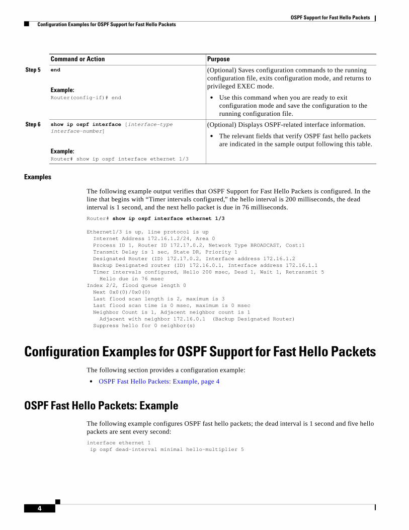
OSPF Support for Fast Hello Packets Configuration Examples for OSPF Support for Fast Hello Packets
4
Examples
The following example output verifies that OSPF Support for Fast Hello Packets is configured. In the line that begins with “Timer intervals configured,” the hello interval is 200 milliseconds, the dead interval is 1 second, and the next hello packet is due in 76 milliseconds.
Router# show ip ospf interface ethernet 1/3
Ethernet1/3 is up, line protocol is up Internet Address 172.16.1.2/24, Area 0 Process ID 1, Router ID 172.17.0.2, Network Type BROADCAST, Cost:1 Transmit Delay is 1 sec, State DR, Priority 1 Designated Router (ID) 172.17.0.2, Interface address 172.16.1.2 Backup Designated router (ID) 172.16.0.1, Interface address 172.16.1.1 Timer intervals configured, Hello 200 msec, Dead 1, Wait 1, Retransmit 5 Hello due in 76 msecIndex 2/2, flood queue length 0 Next 0x0(0)/0x0(0) Last flood scan length is 2, maximum is 3 Last flood scan time is 0 msec, maximum is 0 msec Neighbor Count is 1, Adjacent neighbor count is 1 Adjacent with neighbor 172.16.0.1 (Backup Designated Router) Suppress hello for 0 neighbor(s)
Configuration Examples for OSPF Support for Fast Hello PacketsThe following section provides a configuration example:
• OSPF Fast Hello Packets: Example, page 4
OSPF Fast Hello Packets: ExampleThe following example configures OSPF fast hello packets; the dead interval is 1 second and five hello packets are sent every second:
interface ethernet 1ip ospf dead-interval minimal hello-multiplier 5
Step 5 end
Example:Router(config-if)# end
(Optional) Saves configuration commands to the running configuration file, exits configuration mode, and returns to privileged EXEC mode.
• Use this command when you are ready to exit configuration mode and save the configuration to the running configuration file.
Step 6 show ip ospf interface [interface-type interface-number]
Example:Router# show ip ospf interface ethernet 1/3
(Optional) Displays OSPF-related interface information.
• The relevant fields that verify OSPF fast hello packets are indicated in the sample output following this table.
Command or Action Purpose
OSPF Support for Fast Hello Packets Additional References
5
Additional ReferencesThe following sections provide references related to OSPF Support for Fast Hello Packets.
Related Documents
Standards
MIBs
RFCs
Related Topic Document Title
OSPF commands: complete command syntax, command mode, command history, defaults, usage guidelines, and examples
Cisco IOS IP Routing: OSPF Command Reference
Standards Title
No new or modified standards are supported by this feature, and support for existing standards has not been modified by this feature.
—
MIBs MIBs Link
None To locate and download MIBs for selected platforms, Cisco IOS releases, and feature sets, use Cisco MIB Locator found at the following URL:
http://www.cisco.com/go/mibs
RFCs Title
None —
OSPF Support for Fast Hello Packets Command Reference
6
Technical Assistance
Command ReferenceThe following commands are introduced or modified in the feature or features documented in this module. For information about these commands, see the Cisco IOS IP Routing: OSPF Command Reference. For information about all Cisco IOS commands, go to the Command Lookup Tool at http://tools.cisco.com/Support/CLILookup or to the Cisco IOS Master Commands List.
• ip ospf dead-interval
Description Link
The Cisco Technical Support website contains thousands of pages of searchable technical content, including links to products, technologies, solutions, technical tips, and tools. Registered Cisco.com users can log in from this page to access even more content.
http://www.cisco.com/techsupport
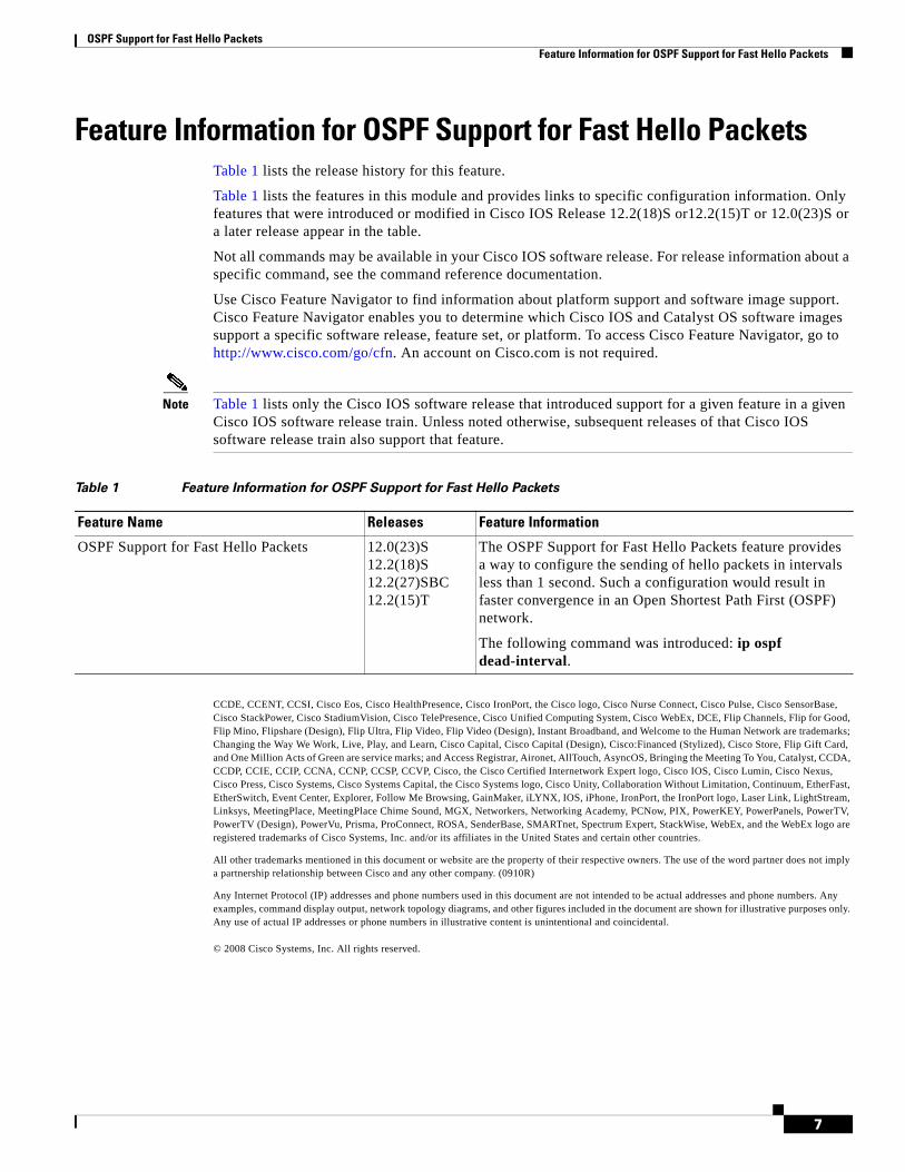
OSPF Support for Fast Hello Packets Feature Information for OSPF Support for Fast Hello Packets
7
Feature Information for OSPF Support for Fast Hello PacketsTable 1 lists the release history for this feature.
Table 1 lists the features in this module and provides links to specific configuration information. Only features that were introduced or modified in Cisco IOS Release 12.2(18)S or12.2(15)T or 12.0(23)S or a later release appear in the table.
Not all commands may be available in your Cisco IOS software release. For release information about a specific command, see the command reference documentation.
Use Cisco Feature Navigator to find information about platform support and software image support. Cisco Feature Navigator enables you to determine which Cisco IOS and Catalyst OS software images support a specific software release, feature set, or platform. To access Cisco Feature Navigator, go to http://www.cisco.com/go/cfn. An account on Cisco.com is not required.
Note Table 1 lists only the Cisco IOS software release that introduced support for a given feature in a given Cisco IOS software release train. Unless noted otherwise, subsequent releases of that Cisco IOS software release train also support that feature.
CCDE, CCENT, CCSI, Cisco Eos, Cisco HealthPresence, Cisco IronPort, the Cisco logo, Cisco Nurse Connect, Cisco Pulse, Cisco SensorBase, Cisco StackPower, Cisco StadiumVision, Cisco TelePresence, Cisco Unified Computing System, Cisco WebEx, DCE, Flip Channels, Flip for Good, Flip Mino, Flipshare (Design), Flip Ultra, Flip Video, Flip Video (Design), Instant Broadband, and Welcome to the Human Network are trademarks; Changing the Way We Work, Live, Play, and Learn, Cisco Capital, Cisco Capital (Design), Cisco:Financed (Stylized), Cisco Store, Flip Gift Card, and One Million Acts of Green are service marks; and Access Registrar, Aironet, AllTouch, AsyncOS, Bringing the Meeting To You, Catalyst, CCDA, CCDP, CCIE, CCIP, CCNA, CCNP, CCSP, CCVP, Cisco, the Cisco Certified Internetwork Expert logo, Cisco IOS, Cisco Lumin, Cisco Nexus, Cisco Press, Cisco Systems, Cisco Systems Capital, the Cisco Systems logo, Cisco Unity, Collaboration Without Limitation, Continuum, EtherFast, EtherSwitch, Event Center, Explorer, Follow Me Browsing, GainMaker, iLYNX, IOS, iPhone, IronPort, the IronPort logo, Laser Link, LightStream, Linksys, MeetingPlace, MeetingPlace Chime Sound, MGX, Networkers, Networking Academy, PCNow, PIX, PowerKEY, PowerPanels, PowerTV, PowerTV (Design), PowerVu, Prisma, ProConnect, ROSA, SenderBase, SMARTnet, Spectrum Expert, StackWise, WebEx, and the WebEx logo are registered trademarks of Cisco Systems, Inc. and/or its affiliates in the United States and certain other countries.
All other trademarks mentioned in this document or website are the property of their respective owners. The use of the word partner does not imply a partnership relationship between Cisco and any other company. (0910R)
Any Internet Protocol (IP) addresses and phone numbers used in this document are not intended to be actual addresses and phone numbers. Any examples, command display output, network topology diagrams, and other figures included in the document are shown for illustrative purposes only. Any use of actual IP addresses or phone numbers in illustrative content is unintentional and coincidental.
© 2008 Cisco Systems, Inc. All rights reserved.
Table 1 Feature Information for OSPF Support for Fast Hello Packets
Feature Name Releases Feature Information
OSPF Support for Fast Hello Packets 12.0(23)S12.2(18)S12.2(27)SBC12.2(15)T
The OSPF Support for Fast Hello Packets feature provides a way to configure the sending of hello packets in intervals less than 1 second. Such a configuration would result in faster convergence in an Open Shortest Path First (OSPF) network.
The following command was introduced: ip ospf dead-interval.

OSPF Support for Fast Hello Packets Feature Information for OSPF Support for Fast Hello Packets
8
Americas Headquarters:Cisco Systems, Inc., 170 West Tasman Drive, San Jose, CA 95134-1706 USA
OSPF Incremental SPF
The Open Shortest Path First (OSPF) protocol can be configured to use an incremental SPF algorithm for calculating the shortest path first routes. Incremental SPF is more efficient than the full SPF algorithm, thereby allowing OSPF to converge faster on a new routing topology in reaction to a network event.
Feature History for the OSPF Incremental SPF Feature
Finding Support Information for Platforms and Cisco IOS Software Images
Use Cisco Feature Navigator to find information about platform support and Cisco IOS software image support. Access Cisco Feature Navigator at http://www.cisco.com/go/fn. You must have an account on Cisco.com. If you do not have an account or have forgotten your username or password, click Cancel at the login dialog box and follow the instructions that appear.
Contents• Prerequisites for OSPF Incremental SPF, page 2
• Information About OSPF Incremental SPF, page 2
• How to Enable OSPF Incremental SPF, page 2
• Configuration Examples for OSPF Incremental SPF, page 3
• Additional References, page 3
• Command Reference, page 5
Release Modification
12.0(24)S This feature was introduced.
12.3(2)T This feature was integrated into Cisco IOS Release 12.3(2)T.
12.2(18)S This feature was integrated into Cisco IOS Release 12.2(18)S.
12.2(27)SBC This feature was integrated into Cisco IOS Release 12.2(27)SBC.
12.2(33)SRA This feature was integrated into Cisco IOS Release 12.2(33)SRA.
OSPF Incremental SPF Prerequisites for OSPF Incremental SPF
2
Prerequisites for OSPF Incremental SPFIt is presumed that you have OSPF configured in your network.
Information About OSPF Incremental SPFBefore you enable OSPF Incremental SPF, you should understand the concept described in this section.
• Benefits of OSPF Incremental SPF, page 2
Benefits of OSPF Incremental SPFOSPF uses Dijkstra’s SPF algorithm to compute the shortest path tree (SPT). During the computation of the SPT, the shortest path to each node is discovered. The topology tree is used to populate the routing table with routes to IP networks. When changes to a Type-1 or Type-2 link-state advertisement (LSA) occur in an area, the entire SPT is recomputed. In many cases, the entire SPT need not be recomputed because most of the tree remains unchanged. Incremental SPF allows the system to recompute only the affected part of the tree. Recomputing only a portion of the tree rather than the entire tree results in faster OSPF convergence and saves CPU resources. Note that if the change to a Type-1 or Type-2 LSA occurs in the calculating router itself, then the full SPT is performed.
Incremental SPF is scheduled in the same way as the full SPF. Routers enabled with incremental SPF and routers not enabled with incremental SPF can function in the same internetwork.
How to Enable OSPF Incremental SPFThis section contains the following procedure:
• Enabling Incremental SPF, page 2
Enabling Incremental SPFThis section describes how to enable incremental SPF.
SUMMARY STEPS
1. enable
2. configure terminal
3. router ospf process-id
4. ispf
5. end
OSPF Incremental SPF Configuration Examples for OSPF Incremental SPF
3
DETAILED STEPS
Configuration Examples for OSPF Incremental SPFThis section contains an example of configuring OSPF incremental SPF:
• Incremental SPF: Example, page 3
Incremental SPF: ExampleThis example enables incremental SPF:
router ospf 1ispf
Additional ReferencesThe following sections provide references related to OSPF Incremental SPF.
Command or Action Purpose
Step 1 enable
Example:Router> enable
Enables privileged EXEC mode.
• Enter your password if prompted.
Step 2 configure terminal
Example:Router# configure terminal
Enters global configuration mode.
Step 3 router ospf process-id
Example:Router(config)# router ospf 1
Configures an OSPF routing process.
Step 4 ispf
Example:Router(config-router)# ispf
Enables incremental SPF.
Step 5 end
Example:Router(config-router)# end
Exits router configuration mode.
OSPF Incremental SPF Additional References
4
Related Documents
Standards
MIBs
RFCs
Technical Assistance
Related Topic Document Title
OSPF commands Cisco IOS IP Routing: OSPF Command Reference
Standards Title
No new or modified standards are supported by this feature, and support for existing standards has not been modified by this feature.
—
MIBs MIBs Link
None To obtain lists of supported MIBs by platform and Cisco IOS release, and to download MIB modules, go to the Cisco MIB website on Cisco.com at the following URL:
http://www.cisco.com/public/sw-center/netmgmt/cmtk/mibs.shtml
RFCs Title
No new or modified RFCs are supported by this feature, and support for existing RFCs has not been modified by this feature.
—
Description Link
Technical Assistance Center (TAC) home page, containing 30,000 pages of searchable technical content, including links to products, technologies, solutions, technical tips, and tools. Registered Cisco.com users can log in from this page to access even more content.
http://www.cisco.com/public/support/tac/home.shtml

OSPF Incremental SPF Command Reference
5
Command ReferenceThe following command is introduced or modified in the feature or features documented in this module. For information about this command, see the Cisco IOS IP Routing: OSPF Command Reference. For information about all Cisco IOS commands, go to the Command Lookup Tool at http://tools.cisco.com/Support/CLILookup or to the Cisco IOS Master Commands List.
• ispf
CCDE, CCENT, CCSI, Cisco Eos, Cisco HealthPresence, Cisco IronPort, the Cisco logo, Cisco Nurse Connect, Cisco Pulse, Cisco SensorBase, Cisco StackPower, Cisco StadiumVision, Cisco TelePresence, Cisco Unified Computing System, Cisco WebEx, DCE, Flip Channels, Flip for Good, Flip Mino, Flipshare (Design), Flip Ultra, Flip Video, Flip Video (Design), Instant Broadband, and Welcome to the Human Network are trademarks; Changing the Way We Work, Live, Play, and Learn, Cisco Capital, Cisco Capital (Design), Cisco:Financed (Stylized), Cisco Store, Flip Gift Card, and One Million Acts of Green are service marks; and Access Registrar, Aironet, AllTouch, AsyncOS, Bringing the Meeting To You, Catalyst, CCDA, CCDP, CCIE, CCIP, CCNA, CCNP, CCSP, CCVP, Cisco, the Cisco Certified Internetwork Expert logo, Cisco IOS, Cisco Lumin, Cisco Nexus, Cisco Press, Cisco Systems, Cisco Systems Capital, the Cisco Systems logo, Cisco Unity, Collaboration Without Limitation, Continuum, EtherFast, EtherSwitch, Event Center, Explorer, Follow Me Browsing, GainMaker, iLYNX, IOS, iPhone, IronPort, the IronPort logo, Laser Link, LightStream, Linksys, MeetingPlace, MeetingPlace Chime Sound, MGX, Networkers, Networking Academy, PCNow, PIX, PowerKEY, PowerPanels, PowerTV, PowerTV (Design), PowerVu, Prisma, ProConnect, ROSA, SenderBase, SMARTnet, Spectrum Expert, StackWise, WebEx, and the WebEx logo are registered trademarks of Cisco Systems, Inc. and/or its affiliates in the United States and certain other countries.
All other trademarks mentioned in this document or website are the property of their respective owners. The use of the word partner does not imply a partnership relationship between Cisco and any other company. (0910R)
Any Internet Protocol (IP) addresses and phone numbers used in this document are not intended to be actual addresses and phone numbers. Any examples, command display output, network topology diagrams, and other figures included in the document are shown for illustrative purposes only. Any use of actual IP addresses or phone numbers in illustrative content is unintentional and coincidental
© 2008 Cisco Systems, Inc. All rights reserved.

OSPF Incremental SPF Command Reference
6
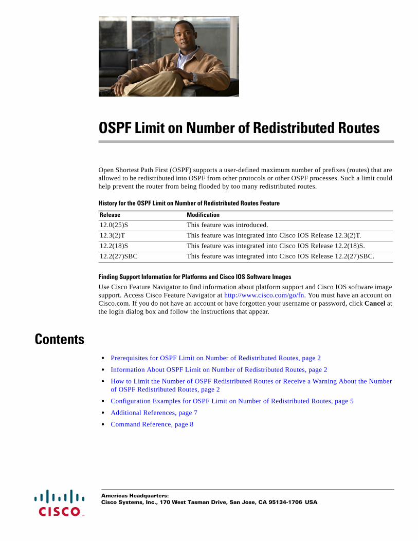
Americas Headquarters:Cisco Systems, Inc., 170 West Tasman Drive, San Jose, CA 95134-1706 USA
OSPF Limit on Number of Redistributed Routes
Open Shortest Path First (OSPF) supports a user-defined maximum number of prefixes (routes) that are allowed to be redistributed into OSPF from other protocols or other OSPF processes. Such a limit could help prevent the router from being flooded by too many redistributed routes.
History for the OSPF Limit on Number of Redistributed Routes Feature
Finding Support Information for Platforms and Cisco IOS Software Images
Use Cisco Feature Navigator to find information about platform support and Cisco IOS software image support. Access Cisco Feature Navigator at http://www.cisco.com/go/fn. You must have an account on Cisco.com. If you do not have an account or have forgotten your username or password, click Cancel at the login dialog box and follow the instructions that appear.
Contents• Prerequisites for OSPF Limit on Number of Redistributed Routes, page 2
• Information About OSPF Limit on Number of Redistributed Routes, page 2
• How to Limit the Number of OSPF Redistributed Routes or Receive a Warning About the Number of OSPF Redistributed Routes, page 2
• Configuration Examples for OSPF Limit on Number of Redistributed Routes, page 5
• Additional References, page 7
• Command Reference, page 8
Release Modification
12.0(25)S This feature was introduced.
12.3(2)T This feature was integrated into Cisco IOS Release 12.3(2)T.
12.2(18)S This feature was integrated into Cisco IOS Release 12.2(18)S.
12.2(27)SBC This feature was integrated into Cisco IOS Release 12.2(27)SBC.
OSPF Limit on Number of Redistributed Routes Prerequisites for OSPF Limit on Number of Redistributed Routes
2
Prerequisites for OSPF Limit on Number of Redistributed RoutesIt is presumed that you have OSPF configured in your network, along with another protocol or another OSPF process you are redistributing.
Information About OSPF Limit on Number of Redistributed Routes
Before you limit the number of OSPF redistributed routes, you should understand the concept described in this section.
• Benefits of OSPF Limit on Number of Redistributed Routes, page 2
Benefits of OSPF Limit on Number of Redistributed RoutesIf someone mistakenly injects a large number of IP routes into OSPF, perhaps by redistributing Border Gateway Protocol (BGP) into OSPF, the network can be severely flooded. Limiting the number of redistributed routes prevents this potential problem.
How to Limit the Number of OSPF Redistributed Routes or Receive a Warning About the Number of OSPF Redistributed Routes
This section contains the following procedures, which are mutually exclusive. That is, you cannot both limit redistributed prefixes and also choose to be warned.
• Limiting the Number of OSPF Redistributed Routes, page 2
• Requesting a Warning About the Number of Routes Redistributed into OSPF, page 4
Limiting the Number of OSPF Redistributed RoutesThis task describes how to limit the number of OSPF redistributed routes. If the number of redistributed routes reaches the maximum value configured, no more routes will be redistributed.
The redistribution limit applies to all IP redistributed prefixes, including summarized ones. The redistribution limit does not apply to default routes or prefixes that are generated as a result of Type-7 to Type-5 translation.
SUMMARY STEPS
1. enable
2. configure terminal
3. router ospf process-id
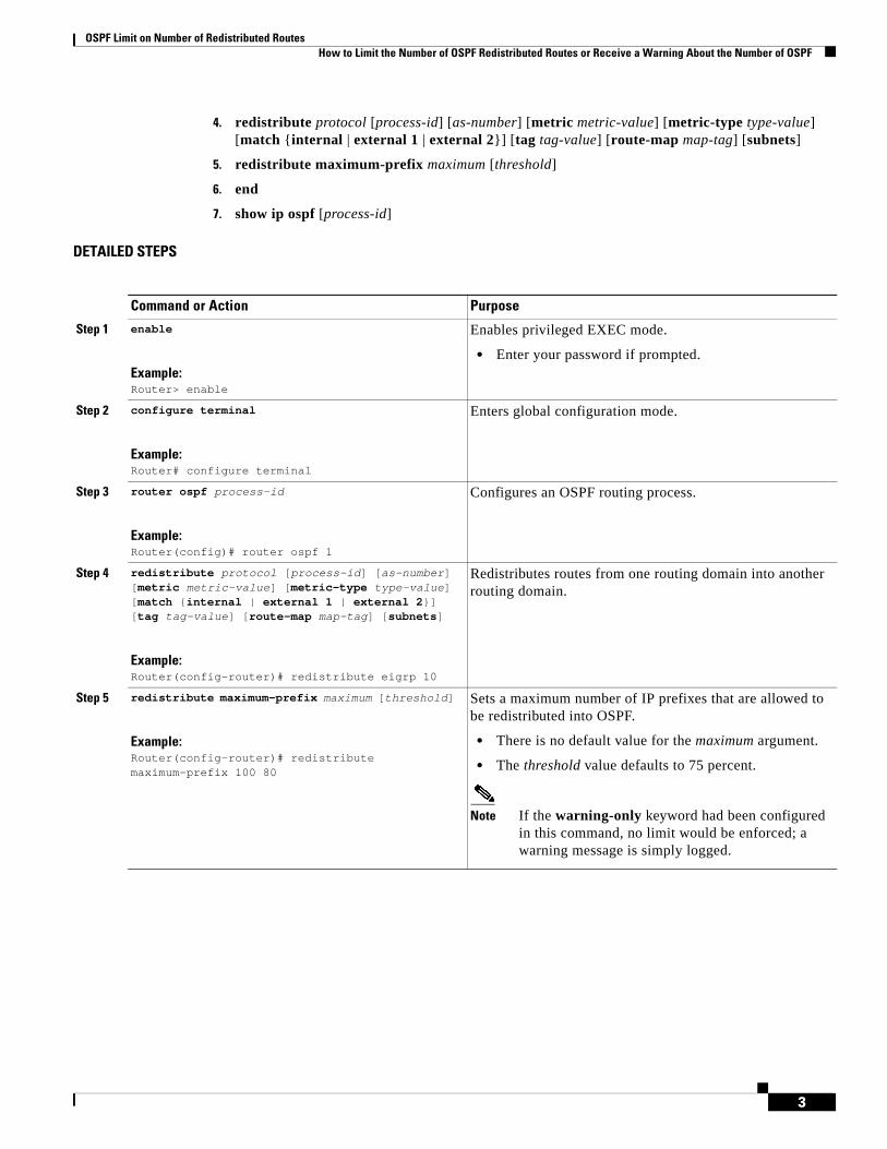
OSPF Limit on Number of Redistributed Routes How to Limit the Number of OSPF Redistributed Routes or Receive a Warning About the Number of OSPF
3
4. redistribute protocol [process-id] [as-number] [metric metric-value] [metric-type type-value] [match {internal | external 1 | external 2}] [tag tag-value] [route-map map-tag] [subnets]
5. redistribute maximum-prefix maximum [threshold]
6. end
7. show ip ospf [process-id]
DETAILED STEPS
Command or Action Purpose
Step 1 enable
Example:Router> enable
Enables privileged EXEC mode.
• Enter your password if prompted.
Step 2 configure terminal
Example:Router# configure terminal
Enters global configuration mode.
Step 3 router ospf process-id
Example:Router(config)# router ospf 1
Configures an OSPF routing process.
Step 4 redistribute protocol [process-id] [as-number] [metric metric-value] [metric-type type-value] [match {internal | external 1 | external 2}] [tag tag-value] [route-map map-tag] [subnets]
Example:Router(config-router)# redistribute eigrp 10
Redistributes routes from one routing domain into another routing domain.
Step 5 redistribute maximum-prefix maximum [threshold]
Example:Router(config-router)# redistribute maximum-prefix 100 80
Sets a maximum number of IP prefixes that are allowed to be redistributed into OSPF.
• There is no default value for the maximum argument.
• The threshold value defaults to 75 percent.
Note If the warning-only keyword had been configured in this command, no limit would be enforced; a warning message is simply logged.
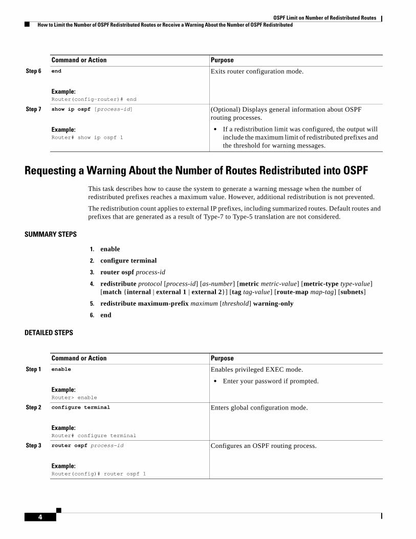
OSPF Limit on Number of Redistributed Routes How to Limit the Number of OSPF Redistributed Routes or Receive a Warning About the Number of OSPF Redistributed
4
Requesting a Warning About the Number of Routes Redistributed into OSPFThis task describes how to cause the system to generate a warning message when the number of redistributed prefixes reaches a maximum value. However, additional redistribution is not prevented.
The redistribution count applies to external IP prefixes, including summarized routes. Default routes and prefixes that are generated as a result of Type-7 to Type-5 translation are not considered.
SUMMARY STEPS
1. enable
2. configure terminal
3. router ospf process-id
4. redistribute protocol [process-id] [as-number] [metric metric-value] [metric-type type-value] [match {internal | external 1 | external 2}] [tag tag-value] [route-map map-tag] [subnets]
5. redistribute maximum-prefix maximum [threshold] warning-only
6. end
DETAILED STEPS
Step 6 end
Example:Router(config-router)# end
Exits router configuration mode.
Step 7 show ip ospf [process-id]
Example:Router# show ip ospf 1
(Optional) Displays general information about OSPF routing processes.
• If a redistribution limit was configured, the output will include the maximum limit of redistributed prefixes and the threshold for warning messages.
Command or Action Purpose
Command or Action Purpose
Step 1 enable
Example:Router> enable
Enables privileged EXEC mode.
• Enter your password if prompted.
Step 2 configure terminal
Example:Router# configure terminal
Enters global configuration mode.
Step 3 router ospf process-id
Example:Router(config)# router ospf 1
Configures an OSPF routing process.
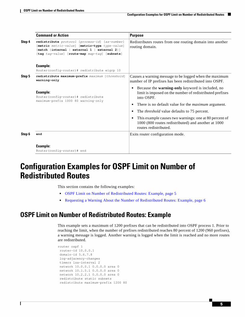
OSPF Limit on Number of Redistributed Routes Configuration Examples for OSPF Limit on Number of Redistributed Routes
5
Configuration Examples for OSPF Limit on Number of Redistributed Routes
This section contains the following examples:
• OSPF Limit on Number of Redistributed Routes: Example, page 5
• Requesting a Warning About the Number of Redistributed Routes: Example, page 6
OSPF Limit on Number of Redistributed Routes: ExampleThis example sets a maximum of 1200 prefixes that can be redistributed into OSPF process 1. Prior to reaching the limit, when the number of prefixes redistributed reaches 80 percent of 1200 (960 prefixes), a warning message is logged. Another warning is logged when the limit is reached and no more routes are redistributed.
router ospf 1router-id 10.0.0.1domain-id 5.6.7.8log-adjacency-changestimers lsa-interval 2network 10.0.0.1 0.0.0.0 area 0network 10.1.5.1 0.0.0.0 area 0network 10.2.2.1 0.0.0.0 area 0redistribute static subnetsredistribute maximum-prefix 1200 80
Step 4 redistribute protocol [process-id] [as-number] [metric metric-value] [metric-type type-value] [match {internal | external 1 | external 2}] [tag tag-value] [route-map map-tag] [subnets]
Example:Router(config-router)# redistribute eigrp 10
Redistributes routes from one routing domain into another routing domain.
Step 5 redistribute maximum-prefix maximum [threshold] warning-only
Example:Router(config-router)# redistribute maximum-prefix 1000 80 warning-only
Causes a warning message to be logged when the maximum number of IP prefixes has been redistributed into OSPF.
• Because the warning-only keyword is included, no limit is imposed on the number of redistributed prefixes into OSPF.
• There is no default value for the maximum argument.
• The threshold value defaults to 75 percent.
• This example causes two warnings: one at 80 percent of 1000 (800 routes redistributed) and another at 1000 routes redistributed.
Step 6 end
Example:Router(config-router)# end
Exits router configuration mode.
Command or Action Purpose

OSPF Limit on Number of Redistributed Routes Configuration Examples for OSPF Limit on Number of Redistributed Routes
6
Requesting a Warning About the Number of Redistributed Routes: ExampleThis example allows two warning messages to be logged, the first if the number of prefixes redistributed reaches 85 percent of 600 (510 prefixes), and the second if the number of redistributed routes reaches 600. However, the number of redistributed routes is not limited.
router ospf 1network 10.0.0.0 0.0.0.255 area 0redistribute eigrp 10 subnetsredistribute maximum-prefix 600 85 warning-only
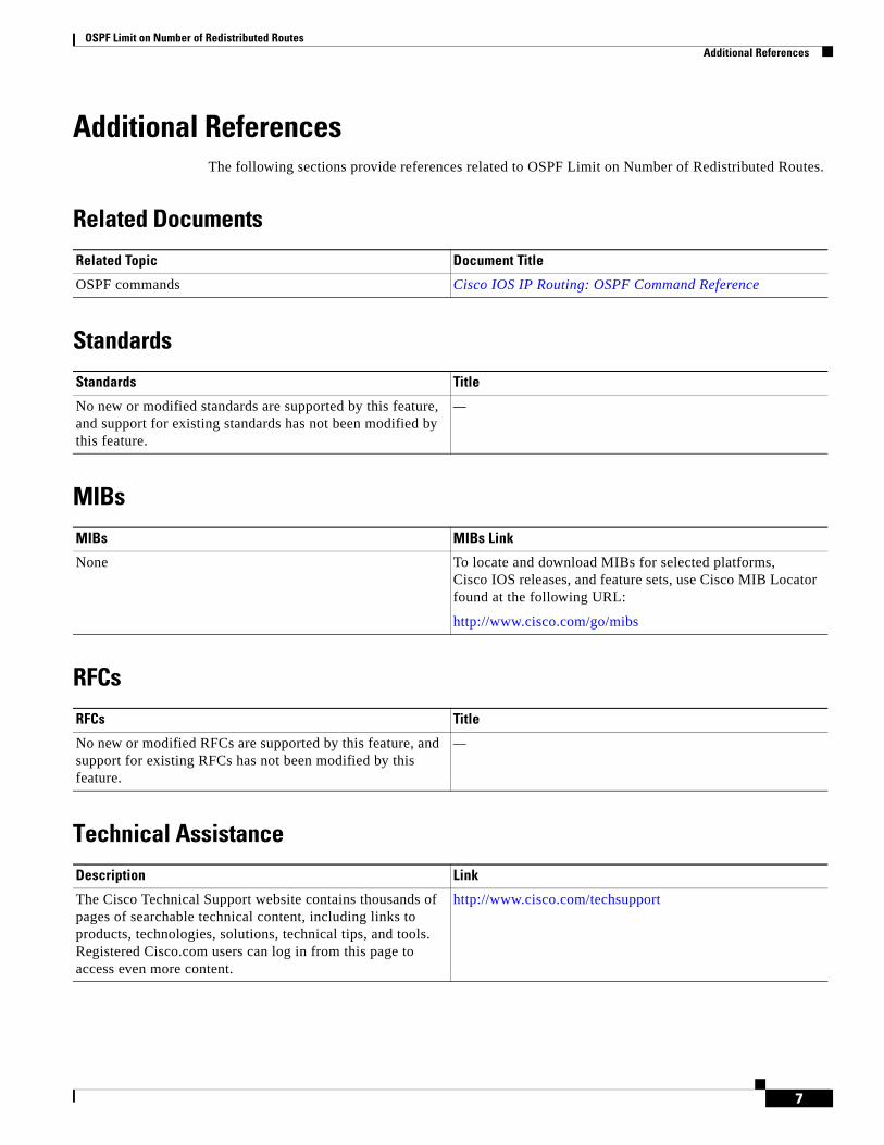
OSPF Limit on Number of Redistributed Routes Additional References
7
Additional ReferencesThe following sections provide references related to OSPF Limit on Number of Redistributed Routes.
Related Documents
Standards
MIBs
RFCs
Technical Assistance
Related Topic Document Title
OSPF commands Cisco IOS IP Routing: OSPF Command Reference
Standards Title
No new or modified standards are supported by this feature, and support for existing standards has not been modified by this feature.
—
MIBs MIBs Link
None To locate and download MIBs for selected platforms, Cisco IOS releases, and feature sets, use Cisco MIB Locator found at the following URL:
http://www.cisco.com/go/mibs
RFCs Title
No new or modified RFCs are supported by this feature, and support for existing RFCs has not been modified by this feature.
—
Description Link
The Cisco Technical Support website contains thousands of pages of searchable technical content, including links to products, technologies, solutions, technical tips, and tools. Registered Cisco.com users can log in from this page to access even more content.
http://www.cisco.com/techsupport
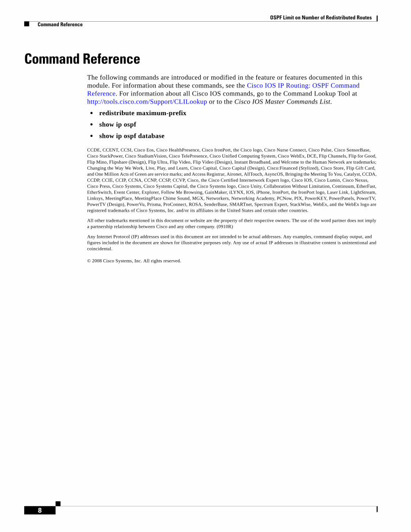
OSPF Limit on Number of Redistributed Routes Command Reference
8
Command ReferenceThe following commands are introduced or modified in the feature or features documented in this module. For information about these commands, see the Cisco IOS IP Routing: OSPF Command Reference. For information about all Cisco IOS commands, go to the Command Lookup Tool at http://tools.cisco.com/Support/CLILookup or to the Cisco IOS Master Commands List.
• redistribute maximum-prefix
• show ip ospf
• show ip ospf database
CCDE, CCENT, CCSI, Cisco Eos, Cisco HealthPresence, Cisco IronPort, the Cisco logo, Cisco Nurse Connect, Cisco Pulse, Cisco SensorBase, Cisco StackPower, Cisco StadiumVision, Cisco TelePresence, Cisco Unified Computing System, Cisco WebEx, DCE, Flip Channels, Flip for Good, Flip Mino, Flipshare (Design), Flip Ultra, Flip Video, Flip Video (Design), Instant Broadband, and Welcome to the Human Network are trademarks; Changing the Way We Work, Live, Play, and Learn, Cisco Capital, Cisco Capital (Design), Cisco:Financed (Stylized), Cisco Store, Flip Gift Card, and One Million Acts of Green are service marks; and Access Registrar, Aironet, AllTouch, AsyncOS, Bringing the Meeting To You, Catalyst, CCDA, CCDP, CCIE, CCIP, CCNA, CCNP, CCSP, CCVP, Cisco, the Cisco Certified Internetwork Expert logo, Cisco IOS, Cisco Lumin, Cisco Nexus, Cisco Press, Cisco Systems, Cisco Systems Capital, the Cisco Systems logo, Cisco Unity, Collaboration Without Limitation, Continuum, EtherFast, EtherSwitch, Event Center, Explorer, Follow Me Browsing, GainMaker, iLYNX, IOS, iPhone, IronPort, the IronPort logo, Laser Link, LightStream, Linksys, MeetingPlace, MeetingPlace Chime Sound, MGX, Networkers, Networking Academy, PCNow, PIX, PowerKEY, PowerPanels, PowerTV, PowerTV (Design), PowerVu, Prisma, ProConnect, ROSA, SenderBase, SMARTnet, Spectrum Expert, StackWise, WebEx, and the WebEx logo are registered trademarks of Cisco Systems, Inc. and/or its affiliates in the United States and certain other countries.
All other trademarks mentioned in this document or website are the property of their respective owners. The use of the word partner does not imply a partnership relationship between Cisco and any other company. (0910R)
Any Internet Protocol (IP) addresses used in this document are not intended to be actual addresses. Any examples, command display output, and figures included in the document are shown for illustrative purposes only. Any use of actual IP addresses in illustrative content is unintentional and coincidental.
© 2008 Cisco Systems, Inc. All rights reserved.

Americas Headquarters:Cisco Systems, Inc., 170 West Tasman Drive, San Jose, CA 95134-1706 USA
OSPF Link-State Advertisement Throttling
The OSPF Link-State Advertisement (LSA) Throttling feature provides a dynamic mechanism to slow down link-state advertisement (LSA) updates in OSPF during times of network instability. It also allows faster Open Shortest Path First (OSPF) convergence by providing LSA rate limiting in milliseconds.
History for the OSPF LSA Throttling Feature
Finding Support Information for Platforms and Cisco IOS Software Images
Use Cisco Feature Navigator to find information about platform support and Cisco IOS software image support. Access Cisco Feature Navigator at http://www.cisco.com/go/fn. You must have an account on Cisco.com. If you do not have an account or have forgotten your username or password, click Cancel at the login dialog box and follow the instructions that appear.
Contents• Prerequisites for OSPF LSA Throttling, page 2
• Information About OSPF LSA Throttling, page 2
• How to Customize OSPF LSA Throttling, page 2
• Configuration Examples for OSPF LSA Throttling, page 5
• Additional References, page 6
• Command Reference, page 7
Release Modification
12.0(25)S This feature was introduced.
12.3(2)T This feature was integrated into Cisco IOS Release 12.3(2)T.
12.2(18)S This feature was integrated into Cisco IOS Release 12.2(18)S.
12.2(27)SBC This feature was integrated into Cisco IOS Release 12.2(27)SBC.
OSPF Link-State Advertisement Throttling Prerequisites for OSPF LSA Throttling
2
Prerequisites for OSPF LSA ThrottlingIt is presumed that you have OSPF configured in your network.
Information About OSPF LSA ThrottlingBefore you enable OSPF LSA Throttling, you should understand the following concepts:
• Benefits of OSPF LSA Throttling, page 2
• How OSPF LSA Throttling Works, page 2
Benefits of OSPF LSA ThrottlingPrior to the OSPF LSA Throttling feature, LSA generation was rate-limited for 5 seconds. That meant that changes in an LSA could not be propagated in milliseconds, so the OSPF network could not achieve millisecond convergence.
The OSPF LSA Throttling feature is enabled by default and allows faster OSPF convergence (in milliseconds). This feature can be customized. One command controls the generation (sending) of LSAs and another command controls the receiving interval. This feature also provides a dynamic mechanism to slow down the frequency of LSA updates in OSPF during times of network instability.
How OSPF LSA Throttling WorksThe timers throttle lsa all command controls the generation (sending) of LSAs. The first LSA is always generated immediately upon an OSPF topology change, and the next LSA generated is controlled by the minimum start interval. The subsequent LSAs generated for the same LSA are rate-limited until the maximum interval is reached. The “same LSA” is defined as an LSA instance that contains the same LSA ID number, LSA type, and advertising router ID.
The timers lsa arrival command controls the minimum interval for accepting the same LSA. If an instance of the same LSA arrives sooner than the interval that is set, the LSA is dropped. It is recommended that the arrival interval be less than or equal to the hold-time interval of the timers throttle lsa all command.
How to Customize OSPF LSA ThrottlingThis section contains the following optional procedure:
• Customizing OSPF LSA Throttling, page 2 (optional)
Customizing OSPF LSA ThrottlingThis task describes how to customize OSPF LSA throttling if you prefer to set values other than the defaults.
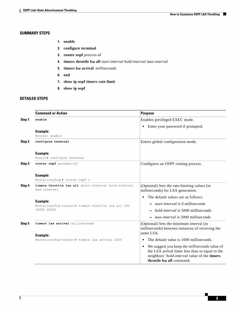
OSPF Link-State Advertisement Throttling How to Customize OSPF LSA Throttling
3
SUMMARY STEPS
1. enable
2. configure terminal
3. router ospf process-id
4. timers throttle lsa all start-interval hold-interval max-interval
5. timers lsa arrival milliseconds
6. end
7. show ip ospf timers rate-limit
8. show ip ospf
DETAILED STEPS
Command or Action Purpose
Step 1 enable
Example:Router> enable
Enables privileged EXEC mode.
• Enter your password if prompted.
Step 2 configure terminal
Example:Router# configure terminal
Enters global configuration mode.
Step 3 router ospf process-id
Example:Router(config)# router ospf 1
Configures an OSPF routing process.
Step 4 timers throttle lsa all start-interval hold-interval max-interval
Example:Router(config-router)# timers throttle lsa all 100 10000 45000
(Optional) Sets the rate-limiting values (in milliseconds) for LSA generation.
• The default values are as follows:
– start-interval is 0 milliseconds
– hold-interval is 5000 milliseconds
– max-interval is 5000 milliseconds
Step 5 timers lsa arrival milliseconds
Example:Router(config-router)# timers lsa arrival 2000
(Optional) Sets the minimum interval (in milliseconds) between instances of receiving the same LSA.
• The default value is 1000 milliseconds.
• We suggest you keep the milliseconds value of the LSA arrival timer less than or equal to the neighbors’ hold-interval value of the timers throttle lsa all command.
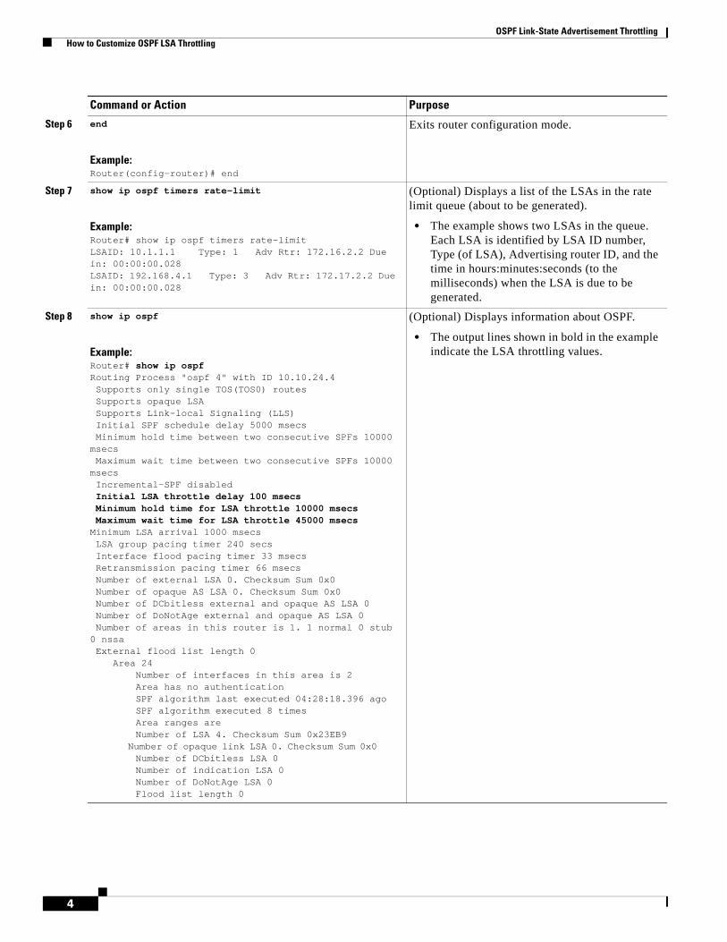
OSPF Link-State Advertisement Throttling How to Customize OSPF LSA Throttling
4
Step 6 end
Example:Router(config-router)# end
Exits router configuration mode.
Step 7 show ip ospf timers rate-limit
Example:Router# show ip ospf timers rate-limitLSAID: 10.1.1.1 Type: 1 Adv Rtr: 172.16.2.2 Due in: 00:00:00.028LSAID: 192.168.4.1 Type: 3 Adv Rtr: 172.17.2.2 Due in: 00:00:00.028
(Optional) Displays a list of the LSAs in the rate limit queue (about to be generated).
• The example shows two LSAs in the queue. Each LSA is identified by LSA ID number, Type (of LSA), Advertising router ID, and the time in hours:minutes:seconds (to the milliseconds) when the LSA is due to be generated.
Step 8 show ip ospf
Example:Router# show ip ospfRouting Process "ospf 4" with ID 10.10.24.4 Supports only single TOS(TOS0) routes Supports opaque LSA Supports Link-local Signaling (LLS) Initial SPF schedule delay 5000 msecs Minimum hold time between two consecutive SPFs 10000 msecs Maximum wait time between two consecutive SPFs 10000 msecs Incremental-SPF disabled Initial LSA throttle delay 100 msecs Minimum hold time for LSA throttle 10000 msecs Maximum wait time for LSA throttle 45000 msecsMinimum LSA arrival 1000 msecs LSA group pacing timer 240 secs Interface flood pacing timer 33 msecs Retransmission pacing timer 66 msecs Number of external LSA 0. Checksum Sum 0x0 Number of opaque AS LSA 0. Checksum Sum 0x0 Number of DCbitless external and opaque AS LSA 0 Number of DoNotAge external and opaque AS LSA 0 Number of areas in this router is 1. 1 normal 0 stub 0 nssa External flood list length 0 Area 24 Number of interfaces in this area is 2 Area has no authentication SPF algorithm last executed 04:28:18.396 ago SPF algorithm executed 8 times Area ranges are Number of LSA 4. Checksum Sum 0x23EB9 Number of opaque link LSA 0. Checksum Sum 0x0 Number of DCbitless LSA 0 Number of indication LSA 0 Number of DoNotAge LSA 0 Flood list length 0
(Optional) Displays information about OSPF.
• The output lines shown in bold in the example indicate the LSA throttling values.
Command or Action Purpose
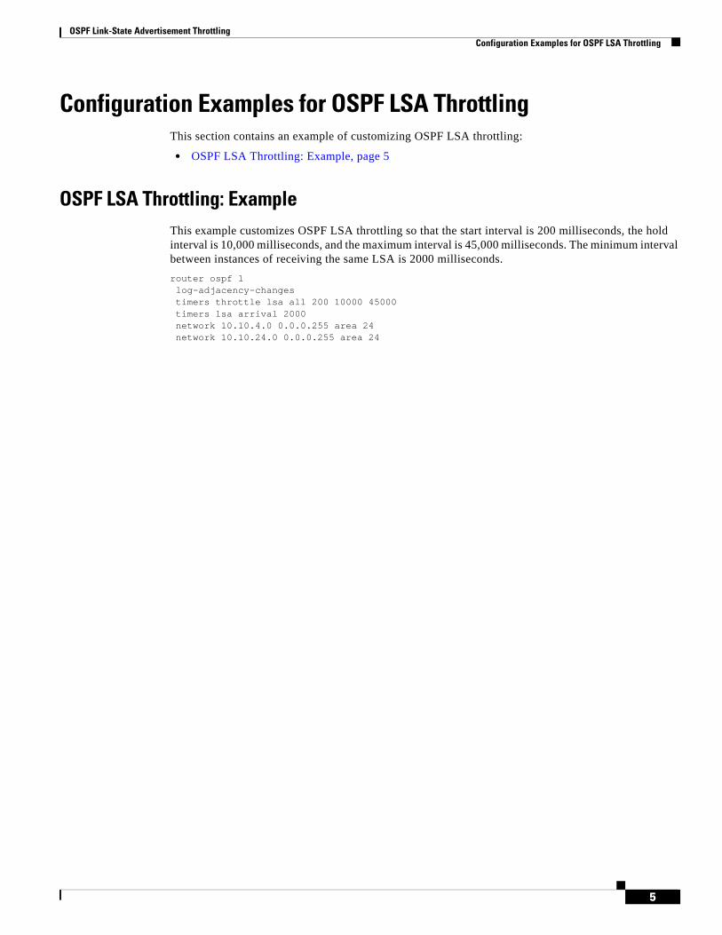
OSPF Link-State Advertisement Throttling Configuration Examples for OSPF LSA Throttling
5
Configuration Examples for OSPF LSA ThrottlingThis section contains an example of customizing OSPF LSA throttling:
• OSPF LSA Throttling: Example, page 5
OSPF LSA Throttling: ExampleThis example customizes OSPF LSA throttling so that the start interval is 200 milliseconds, the hold interval is 10,000 milliseconds, and the maximum interval is 45,000 milliseconds. The minimum interval between instances of receiving the same LSA is 2000 milliseconds.
router ospf 1log-adjacency-changestimers throttle lsa all 200 10000 45000timers lsa arrival 2000network 10.10.4.0 0.0.0.255 area 24network 10.10.24.0 0.0.0.255 area 24

OSPF Link-State Advertisement Throttling Additional References
6
Additional ReferencesThe following sections provide references related to OSPF LSA throttling.
Related Documents
Standards
MIBs
RFCs
Technical Assistance
Related Topic Document Title
OSPF commands Cisco IOS IP Routing: OSPF Command Reference
Standards Title
No new or modified standards are supported by this feature, and support for existing standards has not been modified by this feature.
—
MIBs MIBs Link
None To locate and download MIBs for selected platforms, Cisco IOS releases, and feature sets, use Cisco MIB Locator found at the following URL:
http://www.cisco.com/go/mibs
RFCs Title
No new or modified RFCs are supported by this feature, and support for existing RFCs has not been modified by this feature.
—
Description Link
The Cisco Technical Support website contains thousands of pages of searchable technical content, including links to products, technologies, solutions, technical tips, and tools. Registered Cisco.com users can log in from this page to access even more content.
http://www.cisco.com/techsupport
OSPF Link-State Advertisement Throttling Command Reference
7
Command ReferenceThe following commands are introduced or modified in the feature or features documented in this module. For information about these commands, see the Cisco IOS IP Routing: OSPF Command Reference. For information about all Cisco IOS commands, go to the Command Lookup Tool at http://tools.cisco.com/Support/CLILookup or to the Cisco IOS Master Commands List.
• debug ip ospf database-timer rate-limit
• show ip ospf
• show ip ospf timers rate-limit
• timers lsa arrival
• timers throttle lsa all
CCDE, CCENT, CCSI, Cisco Eos, Cisco HealthPresence, Cisco IronPort, the Cisco logo, Cisco Nurse Connect, Cisco Pulse, Cisco SensorBase, Cisco StackPower, Cisco StadiumVision, Cisco TelePresence, Cisco Unified Computing System, Cisco WebEx, DCE, Flip Channels, Flip for Good, Flip Mino, Flipshare (Design), Flip Ultra, Flip Video, Flip Video (Design), Instant Broadband, and Welcome to the Human Network are trademarks; Changing the Way We Work, Live, Play, and Learn, Cisco Capital, Cisco Capital (Design), Cisco:Financed (Stylized), Cisco Store, Flip Gift Card, and One Million Acts of Green are service marks; and Access Registrar, Aironet, AllTouch, AsyncOS, Bringing the Meeting To You, Catalyst, CCDA, CCDP, CCIE, CCIP, CCNA, CCNP, CCSP, CCVP, Cisco, the Cisco Certified Internetwork Expert logo, Cisco IOS, Cisco Lumin, Cisco Nexus, Cisco Press, Cisco Systems, Cisco Systems Capital, the Cisco Systems logo, Cisco Unity, Collaboration Without Limitation, Continuum, EtherFast, EtherSwitch, Event Center, Explorer, Follow Me Browsing, GainMaker, iLYNX, IOS, iPhone, IronPort, the IronPort logo, Laser Link, LightStream, Linksys, MeetingPlace, MeetingPlace Chime Sound, MGX, Networkers, Networking Academy, PCNow, PIX, PowerKEY, PowerPanels, PowerTV, PowerTV (Design), PowerVu, Prisma, ProConnect, ROSA, SenderBase, SMARTnet, Spectrum Expert, StackWise, WebEx, and the WebEx logo are registered trademarks of Cisco Systems, Inc. and/or its affiliates in the United States and certain other countries.
All other trademarks mentioned in this document or website are the property of their respective owners. The use of the word partner does not imply a partnership relationship between Cisco and any other company. (0910R)
Any Internet Protocol (IP) addresses used in this document are not intended to be actual addresses. Any examples, command display output, and figures included in the document are shown for illustrative purposes only. Any use of actual IP addresses in illustrative content is unintentional and coincidental.
© 2008 Cisco Systems, Inc. All rights reserved.

OSPF Link-State Advertisement Throttling Command Reference
8
Americas Headquarters:Cisco Systems, Inc., 170 West Tasman Drive, San Jose, CA 95134-1706 USA
OSPF Support for Unlimited Software VRFs per Provider Edge Router
In a Multiprotocol Label Switching—Virtual Private Network (MPLS-VPN) deployment, each VPN routing and forwarding instance (VRF) needs a separate Open Shortest Path First (OSPF) process when configured to run OSPF. The OSPF Support for Unlimited Software VRFs per Provider Edge Router feature addresses the scalability issue for OSPF VPNs by eliminating the OSPF VPN limit of 32 processes.
History for the OSPF Support for Unlimited Software VRFs per Provider Edge Router Feature
Finding Support Information for Platforms and Cisco IOS Software Images
Use Cisco Feature Navigator to find information about platform support and Cisco IOS software image support. Access Cisco Feature Navigator at http://www.cisco.com/go/fn. You must have an account on Cisco.com. If you do not have an account or have forgotten your username or password, click Cancel at the login dialog box and follow the instructions that appear.
Contents• Prerequisites for OSPF Support for Unlimited Software VRFs per Provider Edge Router, page 2
• Restrictions for OSPF Support for Unlimited Software VRFs per Provider Edge Router, page 2
• Information About OSPF Support for Unlimited Software VRFs per Provider Edge Router, page 2
• How to Configure the OSPF Support for Unlimited Software VRFs per Provider Edge Router Feature, page 3
Release Modification
12.3(4)T This feature was introduced.
12.0(27)S This feature was integrated into Cisco IOS Release 12.0(27)S.
12.2(25)S This feature was integrated into Cisco IOS Release 12.2(25)S.
12.2(18)SXE This feature was integrated into Cisco IOS Release 12.2(18)SXE.
12.2(27)SBC This feature was integrated into Cisco IOS Release 12.2(27)SBC.
OSPF Support for Unlimited Software VRFs per Provider Edge Router Prerequisites for OSPF Support for Unlimited Software VRFs per Provider Edge Router
2
• Configuration Examples for the OSPF Support for Unlimited Software VRFs per Provider Edge Router Feature, page 4
• Additional References, page 5
• Command Reference, page 6
• Glossary, page 6
Prerequisites for OSPF Support for Unlimited Software VRFs per Provider Edge Router
You must have OSPF configured in your network.
Restrictions for OSPF Support for Unlimited Software VRFs per Provider Edge Router
Only 32 processes per VRF can be supported. For different VRF processes, there is no limit.
Information About OSPF Support for Unlimited Software VRFs per Provider Edge Router
Before you configure the OSPF Support for Unlimited Software VRFs per Provider Edge Router feature, you should understand the following concept:
• Benefits of Having Unlimited Software VRFs per Provider Edge Router, page 2
Benefits of Having Unlimited Software VRFs per Provider Edge RouterBefore Cisco IOS Releases 12.3(4)T and 12.0(27)S, a separate OSPF process was necessary for each VRF that receives VPN routes via OSPF. When VPNs are deployed, an MPLS Provider Edge (PE) router will be running both multiprotocol Border Gateway Protocol (BGP) for VPN distribution, and Interior Gateway Protocol (IGP) for PE-P connectivity. It is a common scenario when OSPF is used as the IGP between a customer edge (CE) router and a PE router. OSPF was not scalable in VPN deployment because of the limit of 32 processes. By default one process is used for connected routes and another process is used for static routes, therefore only 28 processes can be created for VRFs.
The OSPF Support for Unlimited Software VRFs per Provider Edge Router feature allows for an approximate range of 300 to 10,000 VRFs, depending on the particular platform and on the applications, processes, and protocols that are currently running on the platform.
OSPF Support for Unlimited Software VRFs per Provider Edge Router How to Configure the OSPF Support for Unlimited Software VRFs per Provider Edge Router Feature
3
How to Configure the OSPF Support for Unlimited Software VRFs per Provider Edge Router Feature
This section contains the following procedure:
• Configuring and Verifying Unlimited Software VRFs per Provider Edge Router, page 3 (optional)
Configuring and Verifying Unlimited Software VRFs per Provider Edge RouterThis task describes how to configure and verify unlimited software VRFs for OSPF routing.
SUMMARY STEPS
1. enable
2. configure terminal
3. router ospf process-id [vrf vpn-name]
4. end
5. show ip ospf [process-id]
DETAILED STEPS
Command or Action Purpose
Step 1 enable
Example:Router> enable
Enables privileged EXEC mode.
• Enter your password if prompted.
Step 2 configure terminal
Example:Router# configure terminal
Enters global configuration mode.
Step 3 router ospf process-id [vrf vpn-name]
Example:Router(config)# router ospf 1 vrf crf-1
Enables OSPF routing.
• The process-id argument identifies the OSPF process.
• Use the vrf keyword and vpn-name argument to identify a VPN.
Note You now can configure as many OSPF VRF processes as needed.
OSPF Support for Unlimited Software VRFs per Provider Edge Router Configuration Examples for the OSPF Support for Unlimited Software VRFs per Provider Edge Router Feature
4
Configuration Examples for the OSPF Support for Unlimited Software VRFs per Provider Edge Router Feature
This section contains the following configuration examples:
• Configuring the OSPF Support for Unlimited Software VRFs per Provider Edge Router Feature: Example, page 4
• Verifying the OSPF Support for Unlimited Software VRFs per Provider Edge Router Feature: Example, page 4
Configuring the OSPF Support for Unlimited Software VRFs per Provider Edge Router Feature: Example
This example shows a basic OSPF configuration using the router ospf command to configure OSPF VRF processes for the VRFs first, second, and third:
Router> enableRouter# configure terminalRouter(config)# router ospf 12 vrf firstRouter(config)# router ospf 13 vrf secondRouter(config)# router ospf 14 vrf thirdRouter(config)# exit
Verifying the OSPF Support for Unlimited Software VRFs per Provider Edge Router Feature: Example
This example illustrates the output display from the show ip ospf command to verify that the OSPF VRF process 12 has been created for the VRF named first. The output that relates to the VRF first appears in bold.
Router# show ip ospf 12
main ID type 0x0005, value 0.0.0.100Supports only single TOS(TOS0) routesSupports opaque LSASupports Link-local Signaling (LLS)Supports area transit capabilityConnected to MPLS VPN Superbackbone, VRF firstIt is an area border router
Step 4 end
Example:Router(config-router)# end
Returns to privileged EXEC mode.
Step 5 show ip ospf [process-id]
Example:Router# show ip ospf 1
Displays general information about OSPF routing processes.
Command or Action Purpose
OSPF Support for Unlimited Software VRFs per Provider Edge Router Additional References
5
Initial SPF schedule delay 5000 msecsMinimum hold time between two consecutive SPFs 10000 msecsMaximum wait time between two consecutive SPFs 10000 msecsIncremental-SPF disabledMinimum LSA interval 5 secsMinimum LSA arrival 1000 msecsLSA group pacing timer 240 secsInterface flood pacing timer 33 msecsRetransmission pacing timer 66 msecsNumber of external LSA 0. Checksum Sum 0x0Number of opaque AS LSA 0. Checksum Sum 0x0Number of DCbitless external and opaque AS LSA 0Number of DoNotAge external and opaque AS LSA 0Number of areas in this router is 1. 1 normal 0 stub 0 nssaNumber of areas transit capable is 0External flood list length 0
Area BACKBONE(0)Number of interfaces in this area is 1Area has no authenticationSPF algorithm last executed 00:00:15.204 agoSPF algorithm executed 2 timesArea ranges areNumber of LSA 1. Checksum Sum 0xD9F3Number of opaque link LSA 0. Checksum Sum 0x0Number of DCbitless LSA 0Number of indication LSA 0Number of DoNotAge LSA 0Flood list length 0
Additional ReferencesThe following sections provide references related to the OSPF Support for Unlimited Software VRFs per Provider Edge Router feature.
OSPF Support for Unlimited Software VRFs per Provider Edge Router Command Reference
6
Related Documents
Standards
MIBs
RFCs
Technical Assistance
Command ReferenceThis feature uses no new or modified commands.
Glossarymultiprotocol BGP—Border Gateway Protocol (BGP) can be used as an interdomain routing protocol in networks that use Connectionless Network Service (CLNS) as the network-layer protocol.
Related Topic Document Title
Configuring OSPF Cisco IOS IP Routing: OSPF Configuration Guide
Standards Title
None —
MIBs MIBs Link
None To locate and download MIBs for selected platforms, Cisco IOS releases, and feature sets, use Cisco MIB Locator found at the following URL:
http://www.cisco.com/go/mibs
RFCs Title
None —
Description Link
The Cisco Technical Support website contains thousands of pages of searchable technical content, including links to products, technologies, solutions, technical tips, and tools. Registered Cisco.com users can log in from this page to access even more content.
http://www.cisco.com/techsupport
OSPF Support for Unlimited Software VRFs per Provider Edge Router Glossary
7
CCDE, CCENT, CCSI, Cisco Eos, Cisco HealthPresence, Cisco IronPort, the Cisco logo, Cisco Nurse Connect, Cisco Pulse, Cisco SensorBase, Cisco StackPower, Cisco StadiumVision, Cisco TelePresence, Cisco Unified Computing System, Cisco WebEx, DCE, Flip Channels, Flip for Good, Flip Mino, Flipshare (Design), Flip Ultra, Flip Video, Flip Video (Design), Instant Broadband, and Welcome to the Human Network are trademarks; Changing the Way We Work, Live, Play, and Learn, Cisco Capital, Cisco Capital (Design), Cisco:Financed (Stylized), Cisco Store, Flip Gift Card, and One Million Acts of Green are service marks; and Access Registrar, Aironet, AllTouch, AsyncOS, Bringing the Meeting To You, Catalyst, CCDA, CCDP, CCIE, CCIP, CCNA, CCNP, CCSP, CCVP, Cisco, the Cisco Certified Internetwork Expert logo, Cisco IOS, Cisco Lumin, Cisco Nexus, Cisco Press, Cisco Systems, Cisco Systems Capital, the Cisco Systems logo, Cisco Unity, Collaboration Without Limitation, Continuum, EtherFast, EtherSwitch, Event Center, Explorer, Follow Me Browsing, GainMaker, iLYNX, IOS, iPhone, IronPort, the IronPort logo, Laser Link, LightStream, Linksys, MeetingPlace, MeetingPlace Chime Sound, MGX, Networkers, Networking Academy, PCNow, PIX, PowerKEY, PowerPanels, PowerTV, PowerTV (Design), PowerVu, Prisma, ProConnect, ROSA, SenderBase, SMARTnet, Spectrum Expert, StackWise, WebEx, and the WebEx logo are registered trademarks of Cisco Systems, Inc. and/or its affiliates in the United States and certain other countries.
All other trademarks mentioned in this document or website are the property of their respective owners. The use of the word partner does not imply a partnership relationship between Cisco and any other company. (0910R)
Any Internet Protocol (IP) addresses used in this document are not intended to be actual addresses. Any examples, command display output, and figures included in the document are shown for illustrative purposes only. Any use of actual IP addresses in illustrative content is unintentional and coincidental.
© 2008 Cisco Systems, Inc. All rights reserved.

OSPF Support for Unlimited Software VRFs per Provider Edge Router Glossary
8
Americas Headquarters:Cisco Systems, Inc., 170 West Tasman Drive, San Jose, CA 95134-1706 USA
OSPF Area Transit Capability
First Published: January 27, 2004Last Updated: May 2, 2008
The OSPF Area Transit Capability feature provides an OSPF Area Border Router (ABR) with the ability to discover shorter paths through the transit area for forwarding traffic that would normally need to travel through the virtual-link path. This functionality allows Cisco IOS software to be compliant with RFC 2328.
Finding Feature Information in This ModuleYour software release may not support all the features documented in this module. For the latest feature information and caveats, see the release notes for your platform and software release. To find information about the features documented in this module, and to see a list of the releases in which each feature is supported, see the “Feature Information for OSPF Area Transit Capability” section on page 6.
Use Cisco Feature Navigator to find information about platform support and Cisco IOS and Catalyst OS software image support. To access Cisco Feature Navigator, go to http://www.cisco.com/go/cfn. An account on Cisco.com is not required.
Contents• Information About OSPF Area Transit Capability, page 2
• How to Disable OSPF Area Transit Capability, page 2
• Additional References, page 3
• Command Reference, page 5
• Feature Information for OSPF Area Transit Capability, page 6
OSPF Area Transit Capability Information About OSPF Area Transit Capability
2
Information About OSPF Area Transit CapabilityTo use the OSPF Area Transit Capability feature, you should understand the concept in the following section:
• How the OSPF Area Transit Capability Feature Works, page 2
How the OSPF Area Transit Capability Feature WorksThe OSPF Area Transit Capability feature is enabled by default. RFC 2328 defines OSPF area transit capability as the ability of the area to carry data traffic that neither originates nor terminates in the area itself. This capability enables the OSPF ABR to discover shorter paths through the transit area and forward traffic along those paths rather than using the virtual link or path, which are not as optimal.
For a detailed description of OSPF area transit capability, see RFC 2328, OSPF Version 2, at the following URL:
http://www.faqs.org/rfcs/rfc2328.html
How to Disable OSPF Area Transit CapabilityThis section contains the following procedure:
• Disabling OSPF Area Transit Capability on an Area Border Router, page 2 (required)
Disabling OSPF Area Transit Capability on an Area Border RouterThis task describes how to disable the OSPF Area Transit Capability feature on an OSPF ABR.
SUMMARY STEPS
1. enable
2. configure terminal
3. router ospf process-id [vrf vpn-name]
4. no capability transit
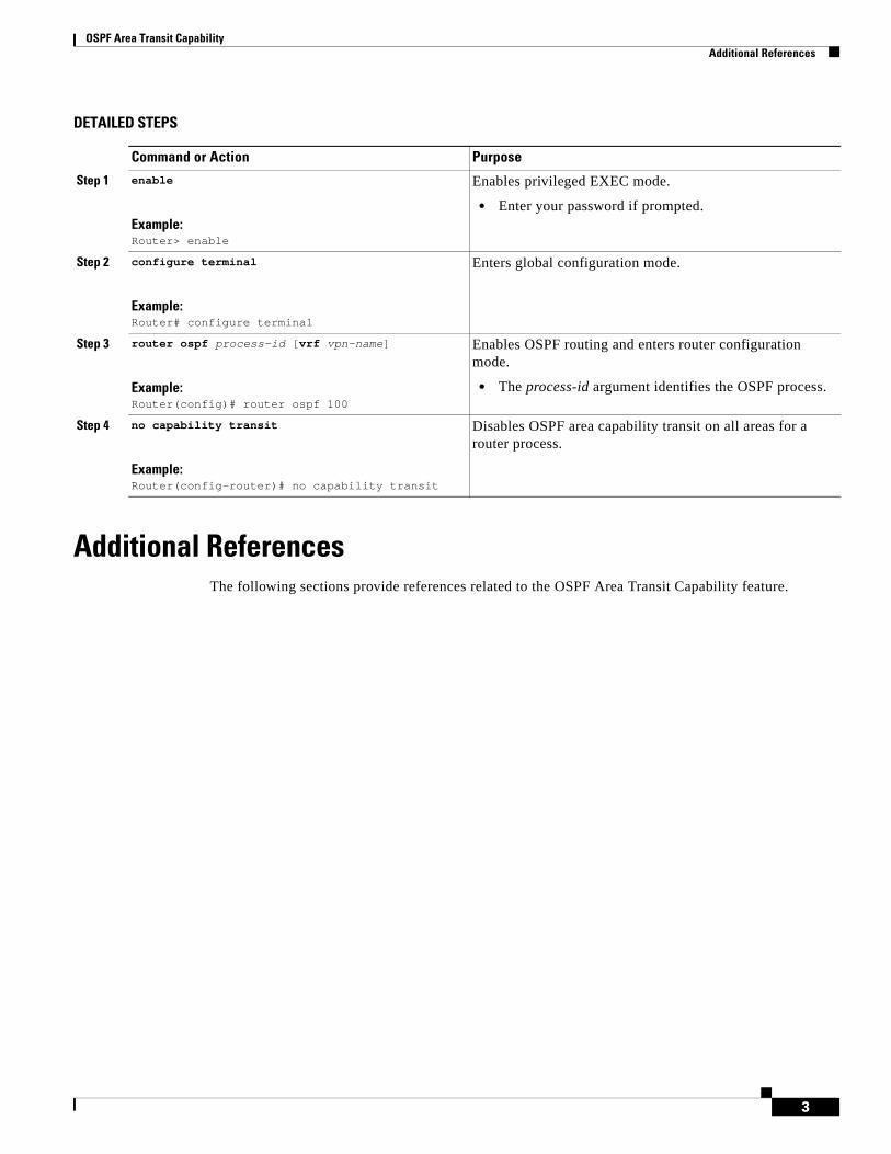
OSPF Area Transit Capability Additional References
3
DETAILED STEPS
Additional ReferencesThe following sections provide references related to the OSPF Area Transit Capability feature.
Command or Action Purpose
Step 1 enable
Example:Router> enable
Enables privileged EXEC mode.
• Enter your password if prompted.
Step 2 configure terminal
Example:Router# configure terminal
Enters global configuration mode.
Step 3 router ospf process-id [vrf vpn-name]
Example:Router(config)# router ospf 100
Enables OSPF routing and enters router configuration mode.
• The process-id argument identifies the OSPF process.
Step 4 no capability transit
Example:Router(config-router)# no capability transit
Disables OSPF area capability transit on all areas for a router process.
OSPF Area Transit Capability Additional References
4
Related Documents
Standards
MIBs
RFCs
Technical Assistance
Related Topic Document Title
Configuring OSPF “Configuring OSPF” module
Standard Title
None —
MIB MIBs Link
None To locate and download MIBs for selected platforms, Cisco IOS releases, and feature sets, use Cisco MIB Locator found at the following URL:
http://www.cisco.com/go/mibs
RFC Title
RFC 2328 OSPF Version 2
Description Link
The Cisco Support website provides extensive online resources, including documentation and tools for troubleshooting and resolving technical issues with Cisco products and technologies.
To receive security and technical information about your products, you can subscribe to various services, such as the Product Alert Tool (accessed from Field Notices), the Cisco Technical Services Newsletter, and Really Simple Syndication (RSS) Feeds.
Access to most tools on the Cisco Support website requires a Cisco.com user ID and password.
http://www.cisco.com/techsupport

OSPF Area Transit Capability Command Reference
5
Command ReferenceThe following commands are introduced or modified in the feature or features documented in this module. For information about these commands, see the IOS IP Routing: OSPF Command Reference. For information about all Cisco IOS commands, go to the Command Lookup Tool at http://tools.cisco.com/Support/CLILookup or to the Cisco IOS Master Commands List.
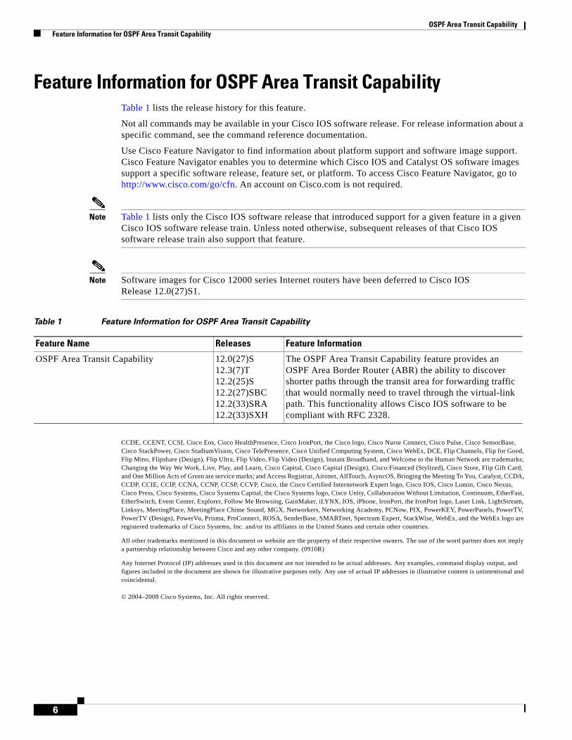
OSPF Area Transit Capability Feature Information for OSPF Area Transit Capability
6
Feature Information for OSPF Area Transit CapabilityTable 1 lists the release history for this feature.
Not all commands may be available in your Cisco IOS software release. For release information about a specific command, see the command reference documentation.
Use Cisco Feature Navigator to find information about platform support and software image support. Cisco Feature Navigator enables you to determine which Cisco IOS and Catalyst OS software images support a specific software release, feature set, or platform. To access Cisco Feature Navigator, go to http://www.cisco.com/go/cfn. An account on Cisco.com is not required.
Note Table 1 lists only the Cisco IOS software release that introduced support for a given feature in a given Cisco IOS software release train. Unless noted otherwise, subsequent releases of that Cisco IOS software release train also support that feature.
Note Software images for Cisco 12000 series Internet routers have been deferred to Cisco IOS Release 12.0(27)S1.
CCDE, CCENT, CCSI, Cisco Eos, Cisco HealthPresence, Cisco IronPort, the Cisco logo, Cisco Nurse Connect, Cisco Pulse, Cisco SensorBase, Cisco StackPower, Cisco StadiumVision, Cisco TelePresence, Cisco Unified Computing System, Cisco WebEx, DCE, Flip Channels, Flip for Good, Flip Mino, Flipshare (Design), Flip Ultra, Flip Video, Flip Video (Design), Instant Broadband, and Welcome to the Human Network are trademarks; Changing the Way We Work, Live, Play, and Learn, Cisco Capital, Cisco Capital (Design), Cisco:Financed (Stylized), Cisco Store, Flip Gift Card, and One Million Acts of Green are service marks; and Access Registrar, Aironet, AllTouch, AsyncOS, Bringing the Meeting To You, Catalyst, CCDA, CCDP, CCIE, CCIP, CCNA, CCNP, CCSP, CCVP, Cisco, the Cisco Certified Internetwork Expert logo, Cisco IOS, Cisco Lumin, Cisco Nexus, Cisco Press, Cisco Systems, Cisco Systems Capital, the Cisco Systems logo, Cisco Unity, Collaboration Without Limitation, Continuum, EtherFast, EtherSwitch, Event Center, Explorer, Follow Me Browsing, GainMaker, iLYNX, IOS, iPhone, IronPort, the IronPort logo, Laser Link, LightStream, Linksys, MeetingPlace, MeetingPlace Chime Sound, MGX, Networkers, Networking Academy, PCNow, PIX, PowerKEY, PowerPanels, PowerTV, PowerTV (Design), PowerVu, Prisma, ProConnect, ROSA, SenderBase, SMARTnet, Spectrum Expert, StackWise, WebEx, and the WebEx logo are registered trademarks of Cisco Systems, Inc. and/or its affiliates in the United States and certain other countries.
All other trademarks mentioned in this document or website are the property of their respective owners. The use of the word partner does not imply a partnership relationship between Cisco and any other company. (0910R)
Any Internet Protocol (IP) addresses used in this document are not intended to be actual addresses. Any examples, command display output, and figures included in the document are shown for illustrative purposes only. Any use of actual IP addresses in illustrative content is unintentional and coincidental.
© 2004–2008 Cisco Systems, Inc. All rights reserved.
Table 1 Feature Information for OSPF Area Transit Capability
Feature Name Releases Feature Information
OSPF Area Transit Capability 12.0(27)S12.3(7)T12.2(25)S12.2(27)SBC12.2(33)SRA12.2(33)SXH
The OSPF Area Transit Capability feature provides an OSPF Area Border Router (ABR) the ability to discover shorter paths through the transit area for forwarding traffic that would normally need to travel through the virtual-link path. This functionality allows Cisco IOS software to be compliant with RFC 2328.
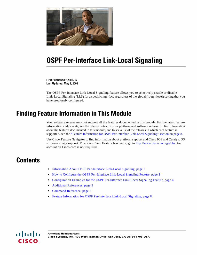
Americas Headquarters:Cisco Systems, Inc., 170 West Tasman Drive, San Jose, CA 95134-1706 USA
OSPF Per-Interface Link-Local Signaling
First Published: 12.0(27)S Last Updated: May 2, 2008
The OSPF Per-Interface Link-Local Signaling feature allows you to selectively enable or disable Link-Local Signaling (LLS) for a specific interface regardless of the global (router level) setting that you have previously configured.
Finding Feature Information in This ModuleYour software release may not support all the features documented in this module. For the latest feature information and caveats, see the release notes for your platform and software release. To find information about the features documented in this module, and to see a list of the releases in which each feature is supported, see the “Feature Information for OSPF Per-Interface Link-Local Signaling” section on page 8.
Use Cisco Feature Navigator to find information about platform support and Cisco IOS and Catalyst OS software image support. To access Cisco Feature Navigator, go to http://www.cisco.com/go/cfn. An account on Cisco.com is not required.
Contents• Information About OSPF Per-Interface Link-Local Signaling, page 2
• How to Configure the OSPF Per-Interface Link-Local Signaling Feature, page 2
• Configuration Examples for the OSPF Per-Interface Link-Local Signaling Feature, page 4
• Additional References, page 5
• Command Reference, page 7
• Feature Information for OSPF Per-Interface Link-Local Signaling, page 8
OSPF Per-Interface Link-Local Signaling Information About OSPF Per-Interface Link-Local Signaling
2
Information About OSPF Per-Interface Link-Local Signaling Before configuring the feature, you should understand the concept in the following section:
• Benefits of the OSPF Per-Interface Link-Local Signaling Feature, page 2
Benefits of the OSPF Per-Interface Link-Local Signaling FeatureLLS allows for the extension of existing OSPF packets in order to provide additional bit space. The additional bit space enables greater information per packet exchange between OSPF neighbors. This functionality is used, for example, by the OSPF Nonstop Forwarding (NSF) Awareness feature that allows customer premises equipment (CPE) routers that are NSF-aware to help NSF-capable routers perform nonstop forwarding of packets.
When LLS is enabled at the router level, it is automatically enabled for all interfaces. The OSPF Per-Interface Link-Local Signaling feature allows you to selectively enable or disable LLS for a specific interface. You may want to disable LLS on a per-interface basis depending on your network design. For example, disabling LLS on an interface that is connected to a non-Cisco device that may be noncompliant with RFC 2328 can prevent problems with the forming of Open Shortest Path First (OSPF) neighbors in the network.
How to Configure the OSPF Per-Interface Link-Local Signaling Feature
This section contains the following procedure:
• Turning Off LLS on a Per-Interface Basis, page 2 (optional)
Turning Off LLS on a Per-Interface BasisThis task disables LLS on a specific interface.
SUMMARY STEPS
1. enable
2. configure terminal
3. interface type slot/port
4. ip address ip-address mask [secondary]
5. no ip directed-broadcast [access-list-number | extended access-list-number]
6. ip ospf message-digest-key key-id encryption-type md5 key
7. [no | default] ip ospf lls [disable]
OSPF Per-Interface Link-Local Signaling How to Configure the OSPF Per-Interface Link-Local Signaling Feature
3
DETAILED STEPS
What to Do Next
To verify that LLS has been enabled or disabled for a specific interface, use the show ip ospf interface command. See the “Configuring and Verifying the OSPF Per-Interface Link-Local Signaling Feature: Example” section on page 4 for an example of the information displayed.
Command or Action Purpose
Step 1 enable
Example:Router> enable
Enables privileged EXEC mode.
• Enter your password if prompted.
Step 2 configure terminal
Example:Router# configure terminal
Enters global configuration mode.
Step 3 interface type slot/port
Example:Router(config)# interface Ethernet 1/0
Configures an interface type and enters interface configuration mode.
Step 4 ip address ip-address mask [secondary]
Example:Router(config-if)# ip address 10.2.145.20 255.255.255.0
Sets a primary or secondary IP address for an interface.
Step 5 no ip directed-broadcast [access-list-number | extended access-list-number]
Example:Router(config-if)# no ip directed-broadcast
Drops directed broadcasts destined for the subnet to which that interface is attached, rather than broadcasting them.
• The forwarding of IP directed broadcasts on Ethernet interface 1/0 is disabled.
Step 6 ip ospf message-digest-key key-id encryption-type md5 key
Example:Router(config-if)# ip ospf message-digest-key 100 md5 testing
Enables OSPF Message Digest 5 (MD5) algorithm authentication.
Step 7 [no | default] ip ospf lls [disable]
Example:Router(config-if)# ip ospf lls disable
Disables LLS on an interface, regardless of the global (router level) setting.

OSPF Per-Interface Link-Local Signaling Configuration Examples for the OSPF Per-Interface Link-Local Signaling Feature
4
Configuration Examples for the OSPF Per-Interface Link-Local Signaling Feature
This section contains the following configuration example:
• Configuring and Verifying the OSPF Per-Interface Link-Local Signaling Feature: Example, page 4
Configuring and Verifying the OSPF Per-Interface Link-Local Signaling Feature: Example
In the following example, LLS has been enabled on Ethernet interface 1/0 and disabled on Ethernet interface 2/0:
interface Ethernet1/0 ip address 10.2.145.2 255.255.255.0 no ip directed-broadcast ip ospf message-digest-key 1 md5 testing ip ospf lls!interface Ethernet2/0 ip address 10.1.145.2 255.255.0.0 no ip directed-broadcast ip ospf message-digest-key 1 md5 testing! ip ospf lls disableinterface Ethernet3/0 ip address 10.3.145.2 255.255.255.0 no ip directed-broadcast!router ospf 1 log-adjacency-changes detail area 0 authentication message-digest redistribute connected subnets network 10.0.0.0 0.255.255.255 area 1 network 10.2.3.0 0.0.0.255 area 1
In the following example, the show ip ospf interface command has been entered to verify that LLS has been enabled for Ethernet interface 1/0 and disabled for interface Ethernet 2/0:
Router# show ip ospf interface
Ethernet1/0 is up, line protocol is up Internet Address 10.2.145.2/24, Area 1 Process ID 1, Router ID 10.22.222.2, Network Type BROADCAST, Cost: 10Transmit Delay is 1 sec, State BDR, Priority 1 Designated Router (ID) 10.2.2.3, Interface address 10.2.145.1Backup Designated router (ID) 10.22.222.2, Interface address 10.2.145.2Timer intervals configured, Hello 10, Dead 40, Wait 40, Retransmit 5
oob-resync timeout 40Hello due in 00:00:00
! Supports Link-local Signaling (LLS)Index 1/1, flood queue length 0
Next 0x0(0)/0x0(0)Last flood scan length is 2, maximum is 8Last flood scan time is 0 msec, maximum is 0 msecNeighbor Count is 1, Adjacent neighbor count is 1
Adjacent with neighbor 10.2.2.3 (Designated Router)Suppress hello for 0 neighbor(s)
Ethernet2/0 is up, line protocol is up
OSPF Per-Interface Link-Local Signaling Additional References
5
Internet Address 10.1.145.2/16, Area 1 Process ID 1, Router ID 10.22.222.2, Network Type BROADCAST, Cost: 10Transmit Delay is 1 sec, State BDR, Priority 1 Designated Router (ID) 10.2.2.3, Interface address 10.1.145.1Backup Designated router (ID) 10.22.222.2, Interface address 10.1.145.2Timer intervals configured, Hello 10, Dead 40, Wait 40, Retransmit 5
oob-resync timeout 40Hello due in 00:00:04
! Does not support Link-local Signaling (LLS)Index 2/2, flood queue length 0
Next 0x0(0)/0x0(0)Last flood scan length is 2, maximum is 11Last flood scan time is 0 msec, maximum is 0 msecNeighbor Count is 1, Adjacent neighbor count is 1
Adjacent with neighbor 45.2.2.3 (Designated Router)Suppress hello for 0 neighbor(s)
Ethernet3/0 is up, line protocol is up Internet Address 10.3.145.2/24, Area 1 Process ID 1, Router ID 10.22.222.2, Network Type BROADCAST, Cost: 10Transmit Delay is 1 sec, State BDR, Priority 1 Designated Router (ID) 10.2.2.3, Interface address 10.3.145.1Backup Designated router (ID) 10.22.222.2, Interface address 10.3.145.2Timer intervals configured, Hello 10, Dead 40, Wait 40, Retransmit 5
oob-resync timeout 40Hello due in 00:00:07
! Supports Link-local Signaling (LLS)Index 3/3, flood queue length 0
Next 0x0(0)/0x0(0)Last flood scan length is 2, maximum is 11Last flood scan time is 0 msec, maximum is 0 msecNeighbor Count is 1, Adjacent neighbor count is 1
Adjacent with neighbor 10.2.2.3 (Designated Router)Suppress hello for 0 neighbor(s)
Additional ReferencesThe following sections provide references related to the OSPF Per-Interface Link-Local Signaling feature.
OSPF Per-Interface Link-Local Signaling Additional References
6
Related Documents
Standards
MIBs
RFCs
Technical Assistance
Related Topic Document Title
Configuring OSPF Configuring OSPF
Configuring OSPF NSF Awareness NSF-OSPF
OSPF commands Cisco IOS IP Routing: OSPF Command Reference
Standards Title
None —
MIBs MIBs Link
None To locate and download MIBs for selected platforms, Cisco IOS releases, and feature sets, use Cisco MIB Locator found at the following URL:
http://www.cisco.com/go/mibs
RFCs Title
RFC 2328 OSPF Version 2
Description Link
The Cisco Technical Support website contains thousands of pages of searchable technical content, including links to products, technologies, solutions, technical tips, and tools. Registered Cisco.com users can log in from this page to access even more content.
http://www.cisco.com/techsupport

OSPF Per-Interface Link-Local Signaling Command Reference
7
Command ReferenceThe following commands are introduced or modified in the feature or features documented in this module. For information about these commands, see the Cisco IOS IP Routing: OSPF Command Reference. For information about all Cisco IOS commands, go to the Command Lookup Tool at http://tools.cisco.com/Support/CLILookup or to the Cisco IOS Master Commands List.
• ip ospf lls

OSPF Per-Interface Link-Local Signaling Feature Information for OSPF Per-Interface Link-Local Signaling
8
Feature Information for OSPF Per-Interface Link-Local SignalingNot all commands may be available in your Cisco IOS software release. For release information about a specific command, see the command reference documentation.
Cisco IOS software images are specific to a Cisco IOS software release, a feature set, and a platform. Use Cisco Feature Navigator to find information about platform support and Cisco IOS software image support. Access Cisco Feature Navigator at http://www.cisco.com/go/fn. You must have an account on Cisco.com. If you do not have an account or have forgotten your username or password, click Cancel at the login dialog box and follow the instructions that appear.
Note Table 1 lists only the Cisco IOS software release that introduced support for a given feature in a given Cisco IOS software release train. Unless noted otherwise, subsequent releases of that Cisco IOS software release train also support that feature.
CCDE, CCENT, CCSI, Cisco Eos, Cisco HealthPresence, Cisco IronPort, the Cisco logo, Cisco Nurse Connect, Cisco Pulse, Cisco SensorBase, Cisco StackPower, Cisco StadiumVision, Cisco TelePresence, Cisco Unified Computing System, Cisco WebEx, DCE, Flip Channels, Flip for Good, Flip Mino, Flipshare (Design), Flip Ultra, Flip Video, Flip Video (Design), Instant Broadband, and Welcome to the Human Network are trademarks; Changing the Way We Work, Live, Play, and Learn, Cisco Capital, Cisco Capital (Design), Cisco:Financed (Stylized), Cisco Store, Flip Gift Card, and One Million Acts of Green are service marks; and Access Registrar, Aironet, AllTouch, AsyncOS, Bringing the Meeting To You, Catalyst, CCDA, CCDP, CCIE, CCIP, CCNA, CCNP, CCSP, CCVP, Cisco, the Cisco Certified Internetwork Expert logo, Cisco IOS, Cisco Lumin, Cisco Nexus, Cisco Press, Cisco Systems, Cisco Systems Capital, the Cisco Systems logo, Cisco Unity, Collaboration Without Limitation, Continuum, EtherFast, EtherSwitch, Event Center, Explorer, Follow Me Browsing, GainMaker, iLYNX, IOS, iPhone, IronPort, the IronPort logo, Laser Link, LightStream, Linksys, MeetingPlace, MeetingPlace Chime Sound, MGX, Networkers, Networking Academy, PCNow, PIX, PowerKEY, PowerPanels, PowerTV, PowerTV (Design), PowerVu, Prisma, ProConnect, ROSA, SenderBase, SMARTnet, Spectrum Expert, StackWise, WebEx, and the WebEx logo are registered trademarks of Cisco Systems, Inc. and/or its affiliates in the United States and certain other countries.
All other trademarks mentioned in this document or website are the property of their respective owners. The use of the word partner does not imply a partnership relationship between Cisco and any other company. (0910R)
Any Internet Protocol (IP) addresses used in this document are not intended to be actual addresses. Any examples, command display output, and figures included in the document are shown for illustrative purposes only. Any use of actual IP addresses in illustrative content is unintentional and coincidental.
© 2008 Cisco Systems, Inc. All rights reserved.
Table 1 Feature Information for OSPF Per-Interface Link-Local Signaling
Feature Name Releases Feature Information
OSPF Per-Interface Link-Local Signaling 12.0(27)S 12.3(7)T12.2(25)S12.2(18)SXE12.2(27)SBC12.2(33)SRA
The OSPF Per-Interface Link-Local Signaling feature allows you to selectively enable or disable Link-Local Signaling (LLS) for a specific interface regardless of the global (router level) setting that you have previously configured.
The following command was introduced or modified: ip ospf lls.
Americas Headquarters:Cisco Systems, Inc., 170 West Tasman Drive, San Jose, CA 95134-1706 USA
OSPF Link-State Database Overload Protection
The OSPF Link-State Database Overload Protection feature allows you to limit the number of nonself-generated link-state advertisements (LSAs) for a given Open Shortest Path First (OSPF) process. Excessive LSAs generated by other routers in the OSPF domain can substantially drain the CPU and memory resources of the router.
History for the OSPF Link-State Database Overload Protection Feature
Finding Support Information for Platforms and Cisco IOS Software Images
Use Cisco Feature Navigator to find information about platform support and Cisco IOS software image support. Access Cisco Feature Navigator at http://www.cisco.com/go/fn. You must have an account on Cisco.com. If you do not have an account or have forgotten your username or password, click Cancel at the login dialog box and follow the instructions that appear.
Contents• Prerequisites for OSPF Link-State Database Overload Protection, page 2
• Information About OSPF Link-State Database Overload Protection, page 2
• How to Configure the OSPF Link-State Database Overload Protection Feature, page 2
• Configuration Examples for the OSPF Link-State Database Overload Protection Feature, page 5
• Additional References, page 7
• Command Reference, page 8
Release Modification
12.0(27)S This feature was introduced.
12.3(7)T This feature was integrated into Cisco IOS Release 12.3(7)T.
12.2(25)S This feature was integrated into Cisco IOS Release 12.2(25)S.
12.2(18)SXE This feature was integrated into Cisco IOS Release 12.2(18)SXE.
12.2(27)SBC This feature was integrated into Cisco IOS Release 12.2(27)SBC.
OSPF Link-State Database Overload Protection Prerequisites for OSPF Link-State Database Overload Protection
2
Prerequisites for OSPF Link-State Database Overload ProtectionIt is presumed you have OSPF running on your network.
Information About OSPF Link-State Database Overload Protection
Before you configure the OSPF Link-State Database Overload Protection feature, you should understand the concepts described in the following sections:
• Benefits of Using OSPF Link-State Database Overload Protection, page 2
• How OSPF Link-State Database Overload Protection Works, page 2
Benefits of Using OSPF Link-State Database Overload ProtectionThe OSPF Link-State Database Overload Protection feature provides a mechanism at the OSPF level to limit the number of nonself-generated LSAs for a given OSPF process. When other routers in the network have been misconfigured, they may generate a high volume of LSAs, for instance, to redistribute large numbers of prefixes. This protection mechanism prevents routers from receiving a large number of LSAs and therefore experiencing CPU and memory shortages.
How OSPF Link-State Database Overload Protection WorksWhen the OSPF Link-State Database Overload Protection feature is enabled, the router keeps a count of the number of received (nonself-generated) LSAs it has received. When the configured threshold number of LSAs is reached, an error message is logged. When the configured maximum number of LSAs is exceeded, the router will send a notification. If the count of received LSAs is still higher than the configured maximum after one minute, the OSPF process takes down all adjacencies and clears the OSPF database. In this ignore state, all OSPF packets received on any interface that belongs to this OSPF process are ignored and no OSPF packets are generated on any of these interfaces. The OSPF process remains in the ignore state for the time configured by the ignore-time keyword of the max-lsa command. Each time the OSPF process gets into an ignore state a counter is incremented. If this counter exceeds the number counts configured by the ignore-count keyword, the OSPF process stays permanently in the same ignore state and manual intervention is required to get the OSPF process out of the ignore state. The ignore state counter is reset to 0 when the OSPF process remains in the normal state of operation for the amount of time that was specified by the reset-time keyword.
If the warning-only keyword of the max-lsa command has been configured, the OSPF process will send only a warning that the LSA maximum has been exceeded.
How to Configure the OSPF Link-State Database Overload Protection Feature
This section contains the following procedure:
• Limiting the Number of Self-Generating LSAs for an OSPF Process, page 3 (required)
OSPF Link-State Database Overload Protection How to Configure the OSPF Link-State Database Overload Protection Feature
3
Limiting the Number of Self-Generating LSAs for an OSPF ProcessThis task describes how to configure and verify a limit on the number of nonself-generating LSAs for an OSPF process.
SUMMARY STEPS
1. enable
2. configure terminal
3. router ospf process-id
4. router-id ip-address
5. log-adjacency-changes [detail]
6. max-lsa maximum-number [threshold-percentage] [warning-only] [ignore-time minutes] [ignore-count count-number] [reset-time minutes]
7. network ip-address wildcard-mask area area-id
DETAILED STEPS
Command or Action Purpose
Step 1 enable
Example:Router> enable
Enables privileged EXEC mode.
• Enter your password if prompted.
Step 2 configure terminal
Example:Router# configure terminal
Enters global configuration mode.
Step 3 router ospf process-id
Example:Router(config)# router ospf 1
Enables OSPF routing.
• The process-id argument identifies the OSPF process.
Step 4 router-id ip-address
Example:Router(config-router)# router-id 10.0.0.1
Specifies a fixed router ID for an OSPF process.
Step 5 log-adjacency-changes [detail]
Example:Router(config-router)# log-adjacency-changes
Configures the router to send a syslog message when an OSPF neighbor goes up or down.
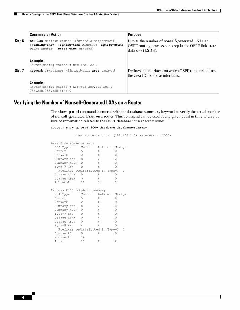
OSPF Link-State Database Overload Protection How to Configure the OSPF Link-State Database Overload Protection Feature
4
Verifying the Number of Nonself-Generated LSAs on a Router
The show ip ospf command is entered with the database-summary keyword to verify the actual number of nonself-generated LSAs on a router. This command can be used at any given point in time to display lists of information related to the OSPF database for a specific router.
Router# show ip ospf 2000 database database-summary
OSPF Router with ID (192.168.1.3) (Process ID 2000)
Area 0 database summaryLSA Type Count Delete MaxageRouter 5 0 0 Network 2 0 0 Summary Net 8 2 2 Summary ASBR 0 0 0 Type-7 Ext 0 0 0
Prefixes redistributed in Type-7 0Opaque Link 0 0 0 Opaque Area 0 0 0 Subtotal 15 2 2
Process 2000 database summaryLSA Type Count Delete MaxageRouter 5 0 0 Network 2 0 0 Summary Net 8 2 2 Summary ASBR 0 0 0 Type-7 Ext 0 0 0 Opaque Link 0 0 0 Opaque Area 0 0 0 Type-5 Ext 4 0 0
Prefixes redistributed in Type-5 0Opaque AS 0 0 0 Non-self 16 Total 19 2 2
Step 6 max-lsa maximum-number [threshold-percentage] [warning-only] [ignore-time minutes] [ignore-count count-number] [reset-time minutes]
Example:Router(config-router)# max-lsa 12000
Limits the number of nonself-generated LSAs an OSPF routing process can keep in the OSPF link-state database (LSDB).
Step 7 network ip-address wildcard-mask area area-id
Example:Router(config-router)# network 209.165.201.1 255.255.255.255 area 0
Defines the interfaces on which OSPF runs and defines the area ID for those interfaces.
Command or Action Purpose
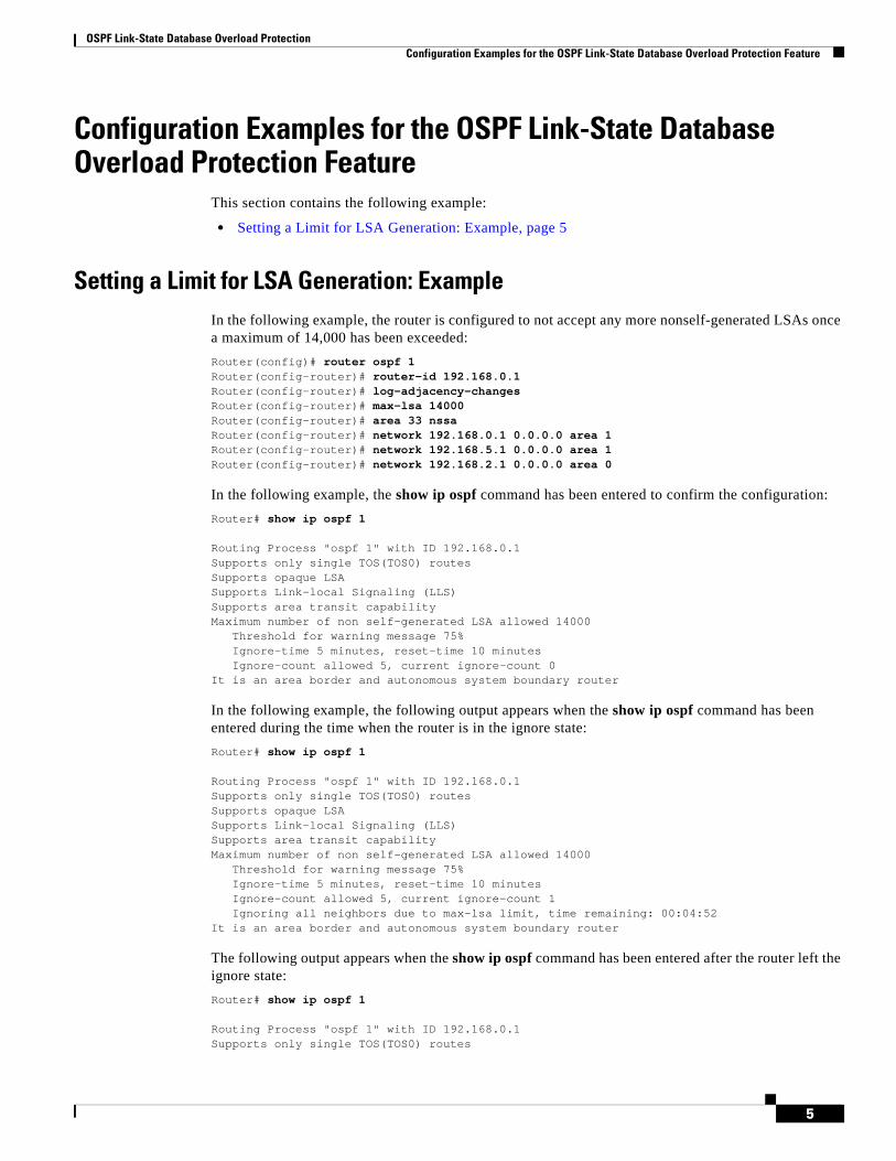
OSPF Link-State Database Overload Protection Configuration Examples for the OSPF Link-State Database Overload Protection Feature
5
Configuration Examples for the OSPF Link-State Database Overload Protection Feature
This section contains the following example:
• Setting a Limit for LSA Generation: Example, page 5
Setting a Limit for LSA Generation: ExampleIn the following example, the router is configured to not accept any more nonself-generated LSAs once a maximum of 14,000 has been exceeded:
Router(config)# router ospf 1Router(config-router)# router-id 192.168.0.1Router(config-router)# log-adjacency-changesRouter(config-router)# max-lsa 14000Router(config-router)# area 33 nssaRouter(config-router)# network 192.168.0.1 0.0.0.0 area 1Router(config-router)# network 192.168.5.1 0.0.0.0 area 1Router(config-router)# network 192.168.2.1 0.0.0.0 area 0
In the following example, the show ip ospf command has been entered to confirm the configuration:
Router# show ip ospf 1
Routing Process "ospf 1" with ID 192.168.0.1Supports only single TOS(TOS0) routesSupports opaque LSASupports Link-local Signaling (LLS)Supports area transit capabilityMaximum number of non self-generated LSA allowed 14000 Threshold for warning message 75% Ignore-time 5 minutes, reset-time 10 minutes Ignore-count allowed 5, current ignore-count 0It is an area border and autonomous system boundary router
In the following example, the following output appears when the show ip ospf command has been entered during the time when the router is in the ignore state:
Router# show ip ospf 1
Routing Process "ospf 1" with ID 192.168.0.1Supports only single TOS(TOS0) routesSupports opaque LSASupports Link-local Signaling (LLS)Supports area transit capabilityMaximum number of non self-generated LSA allowed 14000 Threshold for warning message 75% Ignore-time 5 minutes, reset-time 10 minutes Ignore-count allowed 5, current ignore-count 1 Ignoring all neighbors due to max-lsa limit, time remaining: 00:04:52It is an area border and autonomous system boundary router
The following output appears when the show ip ospf command has been entered after the router left the ignore state:
Router# show ip ospf 1
Routing Process "ospf 1" with ID 192.168.0.1Supports only single TOS(TOS0) routes
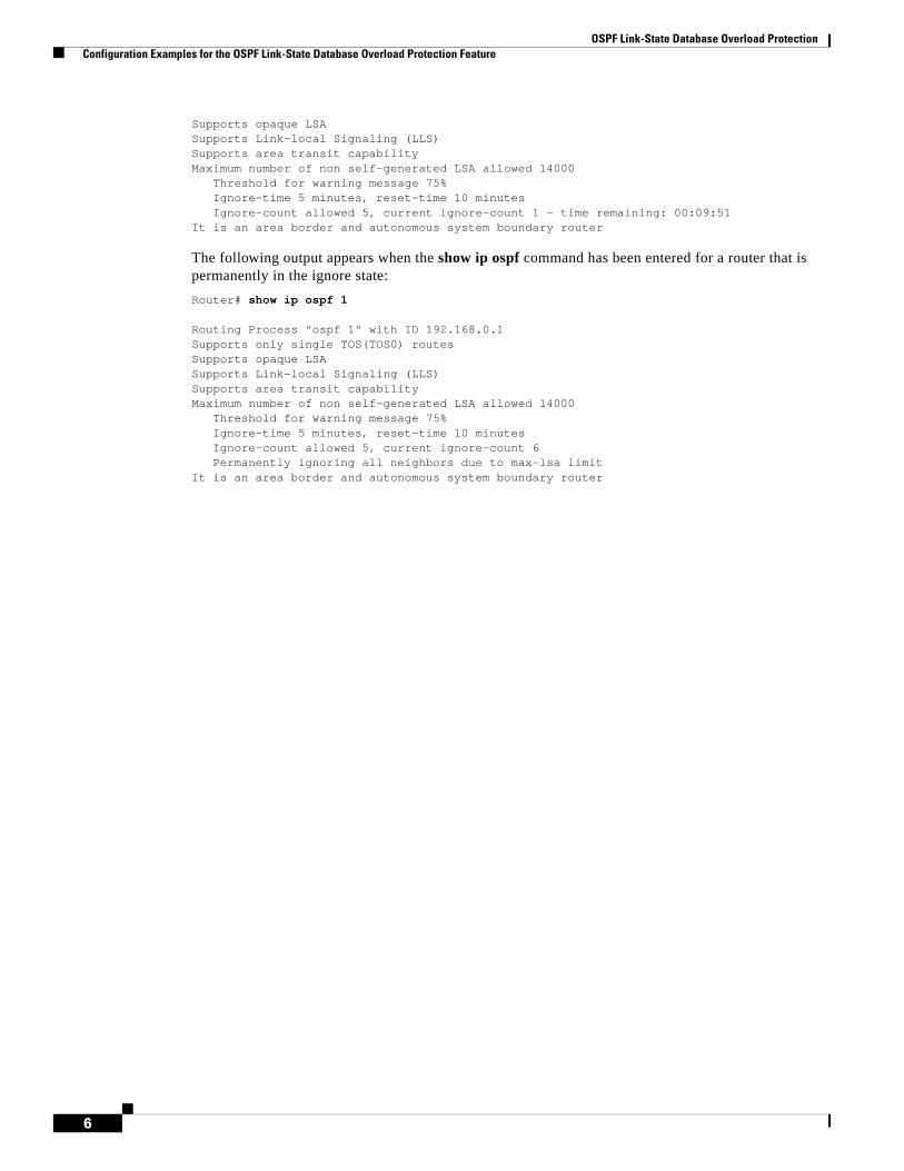
OSPF Link-State Database Overload Protection Configuration Examples for the OSPF Link-State Database Overload Protection Feature
6
Supports opaque LSASupports Link-local Signaling (LLS)Supports area transit capabilityMaximum number of non self-generated LSA allowed 14000 Threshold for warning message 75% Ignore-time 5 minutes, reset-time 10 minutes Ignore-count allowed 5, current ignore-count 1 - time remaining: 00:09:51It is an area border and autonomous system boundary router
The following output appears when the show ip ospf command has been entered for a router that is permanently in the ignore state:
Router# show ip ospf 1
Routing Process "ospf 1" with ID 192.168.0.1Supports only single TOS(TOS0) routesSupports opaque LSASupports Link-local Signaling (LLS)Supports area transit capabilityMaximum number of non self-generated LSA allowed 14000 Threshold for warning message 75% Ignore-time 5 minutes, reset-time 10 minutes Ignore-count allowed 5, current ignore-count 6 Permanently ignoring all neighbors due to max-lsa limitIt is an area border and autonomous system boundary router

OSPF Link-State Database Overload Protection Additional References
7
Additional ReferencesThe following sections provide references related to the OSPF Link-State Database Overload Protection feature.
Related Documents
Standards
MIBs
RFCs
Technical Assistance
Related Topic Document Title
Configuring OSPF • Configuring OSPF module
Standards Title
None —
MIBs MIBs Link
None To locate and download MIBs for selected platforms, Cisco IOS releases, and feature sets, use Cisco MIB Locator found at the following URL:
http://www.cisco.com/go/mibs
RFCs Title
None —
Description Link
The Cisco Technical Support website contains thousands of pages of searchable technical content, including links to products, technologies, solutions, technical tips, and tools. Registered Cisco.com users can log in from this page to access even more content.
http://www.cisco.com/techsupport
OSPF Link-State Database Overload Protection Command Reference
8
Command ReferenceThe following commands are introduced or modified in the feature or features documented in this module. For information about these commands, see the Cisco IOS IP Routing: OSPF Command Reference. For information about all Cisco IOS commands, go to the Command Lookup Tool at http://tools.cisco.com/Support/CLILookup or to the Cisco IOS Master Commands List.
• max-lsa
GlossaryLSDB—link-state database.
CCDE, CCENT, CCSI, Cisco Eos, Cisco HealthPresence, Cisco IronPort, the Cisco logo, Cisco Nurse Connect, Cisco Pulse, Cisco SensorBase, Cisco StackPower, Cisco StadiumVision, Cisco TelePresence, Cisco Unified Computing System, Cisco WebEx, DCE, Flip Channels, Flip for Good, Flip Mino, Flipshare (Design), Flip Ultra, Flip Video, Flip Video (Design), Instant Broadband, and Welcome to the Human Network are trademarks; Changing the Way We Work, Live, Play, and Learn, Cisco Capital, Cisco Capital (Design), Cisco:Financed (Stylized), Cisco Store, Flip Gift Card, and One Million Acts of Green are service marks; and Access Registrar, Aironet, AllTouch, AsyncOS, Bringing the Meeting To You, Catalyst, CCDA, CCDP, CCIE, CCIP, CCNA, CCNP, CCSP, CCVP, Cisco, the Cisco Certified Internetwork Expert logo, Cisco IOS, Cisco Lumin, Cisco Nexus, Cisco Press, Cisco Systems, Cisco Systems Capital, the Cisco Systems logo, Cisco Unity, Collaboration Without Limitation, Continuum, EtherFast, EtherSwitch, Event Center, Explorer, Follow Me Browsing, GainMaker, iLYNX, IOS, iPhone, IronPort, the IronPort logo, Laser Link, LightStream, Linksys, MeetingPlace, MeetingPlace Chime Sound, MGX, Networkers, Networking Academy, PCNow, PIX, PowerKEY, PowerPanels, PowerTV, PowerTV (Design), PowerVu, Prisma, ProConnect, ROSA, SenderBase, SMARTnet, Spectrum Expert, StackWise, WebEx, and the WebEx logo are registered trademarks of Cisco Systems, Inc. and/or its affiliates in the United States and certain other countries.
All other trademarks mentioned in this document or website are the property of their respective owners. The use of the word partner does not imply a partnership relationship between Cisco and any other company. (0910R)
Any Internet Protocol (IP) addresses used in this document are not intended to be actual addresses. Any examples, command display output, and figures included in the document are shown for illustrative purposes only. Any use of actual IP addresses in illustrative content is unintentional and coincidental.
© 2008 Cisco Systems, Inc. All rights reserved.
Americas Headquarters:Cisco Systems, Inc., 170 West Tasman Drive, San Jose, CA 95134-1706 USA
OSPF MIB Support of RFC 1850 and Latest Extensions
First Published: August 23, 2003 Last Updated: May 5, 2008
The OSPF MIB Support of RFC 1850 and Latest Extensions feature introduces the capability for Simple Network Management Protocol (SNMP) monitoring on the Open Shortest Path First (OSPF) routing protocol. Users have an improved ability to constantly monitor the changing state of an OSPF network by use of MIB objects to gather information relating to protocol parameters and trap notification objects that can signal the occurrence of significant network events such as transition state changes. The protocol information collected by the OSPF MIB objects and trap objects can be used to derive statistics that will help monitor and improve overall network performance.
Finding Feature Information in This Module
Your Cisco IOS software release may not support all of the features documented in this module. To reach links to specific feature documentation in this module and to see a list of the releases in which each feature is supported, use the “Feature Information for OSPF MIB Support of RFC 1850 and Latest Extensions” section on page 14.
Finding Support Information for Platforms and Cisco IOS and Catalyst OS Software Images
Use Cisco Feature Navigator to find information about platform support and Cisco IOS and Catalyst OS software image support. To access Cisco Feature Navigator, go to http://www.cisco.com/go/cfn. An account on Cisco.com is not required.
Contents• Prerequisites for OSPF MIB Support of RFC 1850 and Latest Extensions, page 2
• Restrictions for OSPF MIB Support of RFC 1850 and Latest Extensions, page 2
• Information About OSPF MIB Support of RFC 1850 and Latest Extensions, page 2
• How to Enable OSPF MIB Support of RFC 1850 and Latest Extensions, page 7
• Configuration Examples for OSPF MIB Support of RFC 1850 and Latest Extensions, page 12

OSPF MIB Support of RFC 1850 and Latest Extensions Prerequisites for OSPF MIB Support of RFC 1850 and Latest Extensions
2
• Where to Go Next, page 12
• Additional References, page 13
• Command Reference, page 14
• Feature Information for OSPF MIB Support of RFC 1850 and Latest Extensions, page 14
Prerequisites for OSPF MIB Support of RFC 1850 and Latest Extensions
• OSPF must be configured on the router.
• Simple Network Management Protocol (SNMP) must be enabled on the router before notifications (traps) can be configured or before SNMP GET operations can be performed.
Restrictions for OSPF MIB Support of RFC 1850 and Latest Extensions
For routers that are running Cisco IOS Release 12.0(26)S, 12.2(25)S, 12.2(27)SBC, 12.2(31)SB2 and later releases, the OSPF MIB and CISCO OSPF MIB will be supported only for the first OSPF process (except for MIB objects that are related to virtual links and sham links, and in cases where support for multiple topologies is provided). SNMP traps will be generated for OSPF events that are related to any of the OSPF processes. There is no workaround for this situation.
Information About OSPF MIB Support of RFC 1850 and Latest Extensions
The following sections contain information about MIB objects standardized as part of RFC 1850 and defined in OSPF-MIB and OSPF-TRAP-MIB. In addition, extensions to RFC 1850 objects are described as defined in the two Cisco private MIBs, CISCO-OSPF-MIB and CISCO-OSPF-TRAP-MIB.
• OSPF MIB Changes to Support RFC 1850, page 2
• Benefits of the OSPF MIB, page 7
OSPF MIB Changes to Support RFC 1850The following sections describe the new MIB objects that provide RFC 1850 support:
• OSPF MIB, page 3
• OSPF TRAP MIB, page 4
• CISCO OSPF MIB, page 4
• CISCO OSPF TRAP MIB, page 6
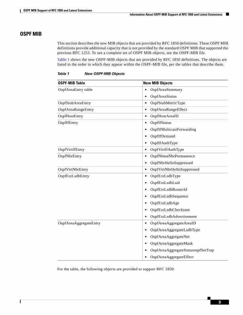
OSPF MIB Support of RFC 1850 and Latest Extensions Information About OSPF MIB Support of RFC 1850 and Latest Extensions
3
OSPF MIB
This section describes the new MIB objects that are provided by RFC 1850 definitions. These OSPF MIB definitions provide additional capacity that is not provided by the standard OSPF MIB that supported the previous RFC 1253. To see a complete set of OSPF MIB objects, see the OSPF-MIB file.
Table 1 shows the new OSPF-MIB objects that are provided by RFC 1850 definitions. The objects are listed in the order in which they appear within the OSPF-MIB file, per the tables that describe them.
For the table, the following objects are provided to support RFC 1850:
Table 1 New OSPF-MIB Objects
OSPF-MIB Table New MIB Objects
OspfAreaEntry table • OspfAreaSummary
• OspfAreaStatus
OspfStubAreaEntry • OspfStubMetricType
OspfAreaRangeEntry • OspfAreaRangeEffect
OspfHostEntry • OspfHostAreaID
OspfIfEntry • OspfIfStatus
• OspfIfMulticastForwarding
• OspfIfDemand
• OspfIfAuthType
OspfVirtIfEntry • OspfVirtIfAuthType
OspfNbrEntry • OspfNbmaNbrPermanence
• OspfNbrHelloSuppressed
OspfVirtNbrEntry • OspfVirtNbrHelloSuppressed
OspfExtLsdbEntry • OspfExtLsdbType
• OspfExtLsdbLsid
• OspfExtLsdbRouterId
• OspfExtLsdbSequence
• OspfExtLsdbAge
• OspfExtLsdbChecksum
• OspfExtLsdbAdvertisement
OspfAreaAggregateEntry • OspfAreaAggregateAreaID
• OspfAreaAggregateLsdbType
• OspfAreaAggregateNet
• OspfAreaAggregateMask
• OspfAreaAggregateStatusospfSetTrap
• OspfAreaAggregateEffect
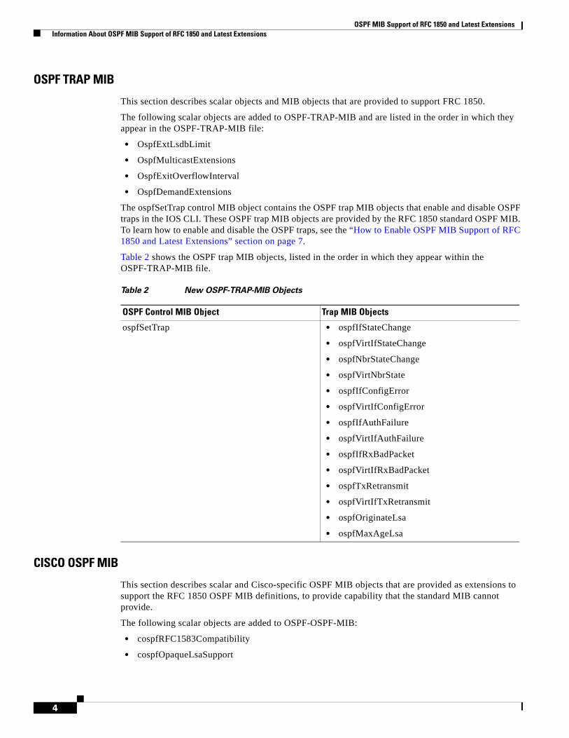
OSPF MIB Support of RFC 1850 and Latest Extensions Information About OSPF MIB Support of RFC 1850 and Latest Extensions
4
OSPF TRAP MIB
This section describes scalar objects and MIB objects that are provided to support FRC 1850.
The following scalar objects are added to OSPF-TRAP-MIB and are listed in the order in which they appear in the OSPF-TRAP-MIB file:
• OspfExtLsdbLimit
• OspfMulticastExtensions
• OspfExitOverflowInterval
• OspfDemandExtensions
The ospfSetTrap control MIB object contains the OSPF trap MIB objects that enable and disable OSPF traps in the IOS CLI. These OSPF trap MIB objects are provided by the RFC 1850 standard OSPF MIB. To learn how to enable and disable the OSPF traps, see the “How to Enable OSPF MIB Support of RFC 1850 and Latest Extensions” section on page 7.
Table 2 shows the OSPF trap MIB objects, listed in the order in which they appear within the OSPF-TRAP-MIB file.
CISCO OSPF MIB
This section describes scalar and Cisco-specific OSPF MIB objects that are provided as extensions to support the RFC 1850 OSPF MIB definitions, to provide capability that the standard MIB cannot provide.
The following scalar objects are added to OSPF-OSPF-MIB:
• cospfRFC1583Compatibility
• cospfOpaqueLsaSupport
Table 2 New OSPF-TRAP-MIB Objects
OSPF Control MIB Object Trap MIB Objects
ospfSetTrap • ospfIfStateChange
• ospfVirtIfStateChange
• ospfNbrStateChange
• ospfVirtNbrState
• ospfIfConfigError
• ospfVirtIfConfigError
• ospfIfAuthFailure
• ospfVirtIfAuthFailure
• ospfIfRxBadPacket
• ospfVirtIfRxBadPacket
• ospfTxRetransmit
• ospfVirtIfTxRetransmit
• ospfOriginateLsa
• ospfMaxAgeLsa
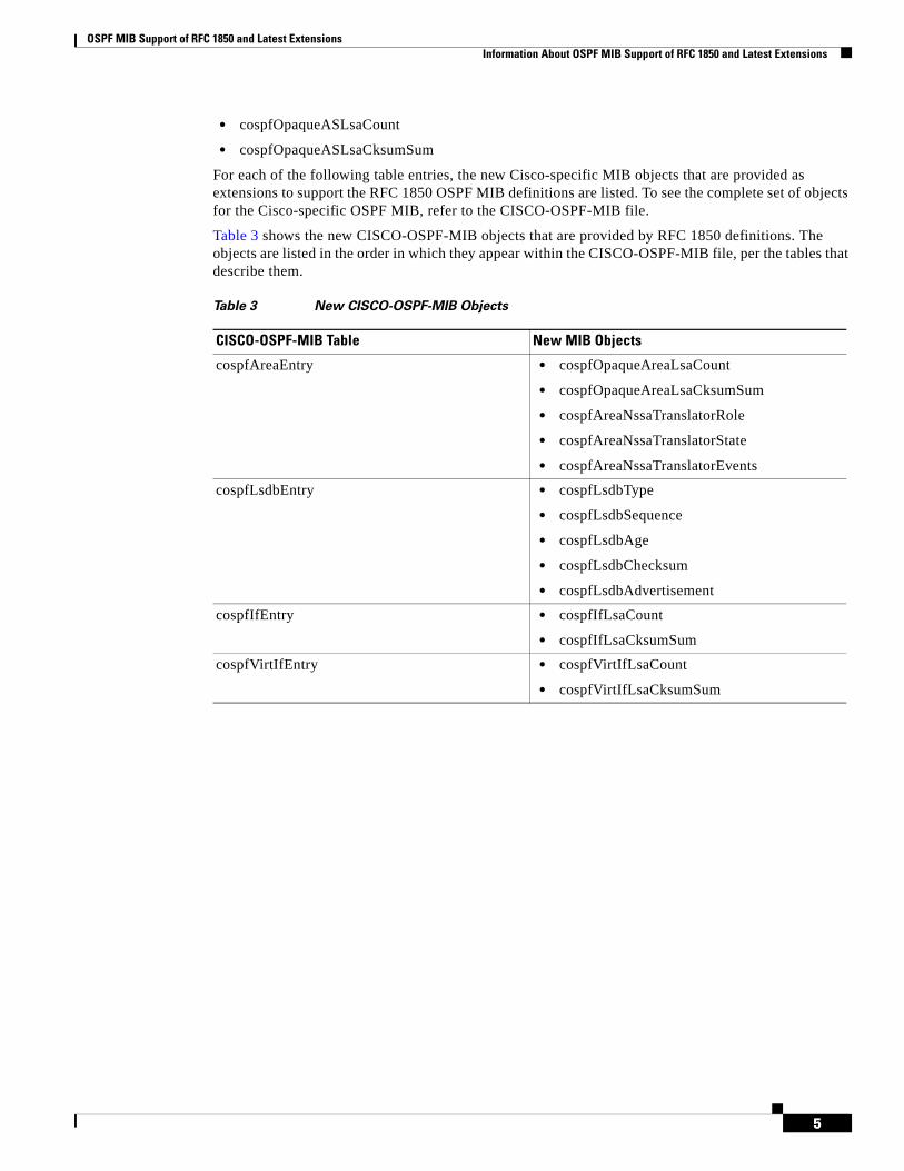
OSPF MIB Support of RFC 1850 and Latest Extensions Information About OSPF MIB Support of RFC 1850 and Latest Extensions
5
• cospfOpaqueASLsaCount
• cospfOpaqueASLsaCksumSum
For each of the following table entries, the new Cisco-specific MIB objects that are provided as extensions to support the RFC 1850 OSPF MIB definitions are listed. To see the complete set of objects for the Cisco-specific OSPF MIB, refer to the CISCO-OSPF-MIB file.
Table 3 shows the new CISCO-OSPF-MIB objects that are provided by RFC 1850 definitions. The objects are listed in the order in which they appear within the CISCO-OSPF-MIB file, per the tables that describe them.
Table 3 New CISCO-OSPF-MIB Objects
CISCO-OSPF-MIB Table New MIB Objects
cospfAreaEntry • cospfOpaqueAreaLsaCount
• cospfOpaqueAreaLsaCksumSum
• cospfAreaNssaTranslatorRole
• cospfAreaNssaTranslatorState
• cospfAreaNssaTranslatorEvents
cospfLsdbEntry • cospfLsdbType
• cospfLsdbSequence
• cospfLsdbAge
• cospfLsdbChecksum
• cospfLsdbAdvertisement
cospfIfEntry • cospfIfLsaCount
• cospfIfLsaCksumSum
cospfVirtIfEntry • cospfVirtIfLsaCount
• cospfVirtIfLsaCksumSum
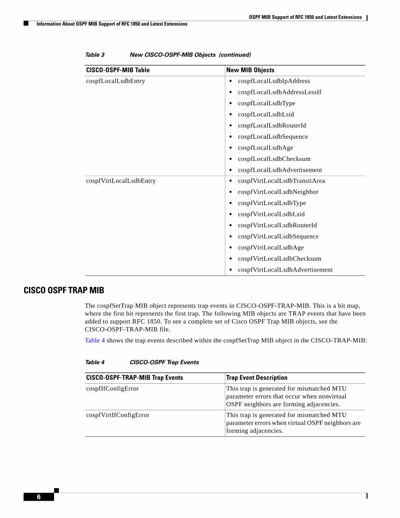
OSPF MIB Support of RFC 1850 and Latest Extensions Information About OSPF MIB Support of RFC 1850 and Latest Extensions
6
CISCO OSPF TRAP MIB
The cospfSetTrap MIB object represents trap events in CISCO-OSPF-TRAP-MIB. This is a bit map, where the first bit represents the first trap. The following MIB objects are TRAP events that have been added to support RFC 1850. To see a complete set of Cisco OSPF Trap MIB objects, see the CISCO-OSPF-TRAP-MIB file.
Table 4 shows the trap events described within the cospfSetTrap MIB object in the CISCO-TRAP-MIB:
cospfLocalLsdbEntry • cospfLocalLsdbIpAddress
• cospfLocalLsdbAddressLessIf
• cospfLocalLsdbType
• cospfLocalLsdbLsid
• cospfLocalLsdbRouterId
• cospfLocalLsdbSequence
• cospfLocalLsdbAge
• cospfLocalLsdbChecksum
• cospfLocalLsdbAdvertisement
cospfVirtLocalLsdbEntry • cospfVirtLocalLsdbTransitArea
• cospfVirtLocalLsdbNeighbor
• cospfVirtLocalLsdbType
• cospfVirtLocalLsdbLsid
• cospfVirtLocalLsdbRouterId
• cospfVirtLocalLsdbSequence
• cospfVirtLocalLsdbAge
• cospfVirtLocalLsdbChecksum
• cospfVirtLocalLsdbAdvertisement
Table 3 New CISCO-OSPF-MIB Objects (continued)
CISCO-OSPF-MIB Table New MIB Objects
Table 4 CISCO-OSPF Trap Events
CISCO-OSPF-TRAP-MIB Trap Events Trap Event Description
cospfIfConfigError This trap is generated for mismatched MTU parameter errors that occur when nonvirtual OSPF neighbors are forming adjacencies.
cospfVirtIfConfigError This trap is generated for mismatched MTU parameter errors when virtual OSPF neighbors are forming adjacencies.

OSPF MIB Support of RFC 1850 and Latest Extensions How to Enable OSPF MIB Support of RFC 1850 and Latest Extensions
7
For information about how to enable OSPF MIB traps, see the “How to Enable OSPF MIB Support of RFC 1850 and Latest Extensions” section on page 7.
Benefits of the OSPF MIBThe OSPF MIBs (OSPF-MIB and OSPF-TRAP-MIB) and Cisco private OSPF MIBs (CISCO-OSPF-MIB and CISCO-OSPF-TRAP-MIB) allow network managers to more effectively monitor the OSPF routing protocol through the addition of new table objects and trap notification objects that previously were not supported by the RFC 1253 OSPF MIB.
New CLI commands have been added to enable SNMP notifications for OSPF MIB support objects, Cisco-specific errors, retransmission and state-change traps. The SNMP notifications are provided for errors and other significant event information for the OSPF network.
How to Enable OSPF MIB Support of RFC 1850 and Latest Extensions
This section describes the configuration tasks for the OSPF MIB Support feature. Each task in the list is identified as either required or optional.
• Enabling OSPF MIB Support, page 8 (required)
• Enabling Specific OSPF Traps, page 9 (optional)
• Verifying OSPF MIB Traps on the Router, page 11 (optional)
cospfTxRetransmit This trap is generated in the case of opaque LSAs when packets are sent by a nonvirtual interface. An opaque link-state advertisement (LSA) is used in MPLS traffic engineering to distribute attributes such as capacity and topology of links in a network. The scope of this LSA can be confined to the local network (Type 9, Link-Local), OSPF area (Type 20, Area-Local), or autonomous system (Type 11, AS scope). The information in an opaque LSA can be used by an external application across the OSPF network.
cospfVirtIfTxRetransmit This trap is generated in the case of opaque LSAs when packets are sent by a virtual interface.
cospfOriginateLsa This trap is generated when a new opaque LSA is originated by the router when a topology change has occurred.
cospfMaxAgeLsa The trap is generated in the case of opaque LSAs.
cospfNssaTranslatorStatusChange The trap is generated if there is a change in the ability of a router to translate OSPF type-7 LSAs into OSPF type-5 LSAs.
Table 4 CISCO-OSPF Trap Events (continued)
CISCO-OSPF-TRAP-MIB Trap Events Trap Event Description
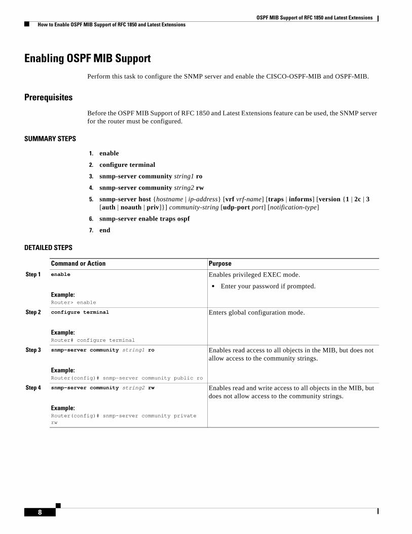
OSPF MIB Support of RFC 1850 and Latest Extensions How to Enable OSPF MIB Support of RFC 1850 and Latest Extensions
8
Enabling OSPF MIB SupportPerform this task to configure the SNMP server and enable the CISCO-OSPF-MIB and OSPF-MIB.
Prerequisites
Before the OSPF MIB Support of RFC 1850 and Latest Extensions feature can be used, the SNMP server for the router must be configured.
SUMMARY STEPS
1. enable
2. configure terminal
3. snmp-server community string1 ro
4. snmp-server community string2 rw
5. snmp-server host {hostname | ip-address} [vrf vrf-name] [traps | informs] [version {1 | 2c | 3 [auth | noauth | priv]}] community-string [udp-port port] [notification-type]
6. snmp-server enable traps ospf
7. end
DETAILED STEPS
Command or Action Purpose
Step 1 enable
Example:Router> enable
Enables privileged EXEC mode.
• Enter your password if prompted.
Step 2 configure terminal
Example:Router# configure terminal
Enters global configuration mode.
Step 3 snmp-server community string1 ro
Example:Router(config)# snmp-server community public ro
Enables read access to all objects in the MIB, but does not allow access to the community strings.
Step 4 snmp-server community string2 rw
Example:Router(config)# snmp-server community private rw
Enables read and write access to all objects in the MIB, but does not allow access to the community strings.
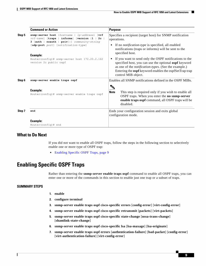
OSPF MIB Support of RFC 1850 and Latest Extensions How to Enable OSPF MIB Support of RFC 1850 and Latest Extensions
9
What to Do Next
If you did not want to enable all OSPF traps, follow the steps in the following section to selectively enable one or more type of OSPF trap:
• Enabling Specific OSPF Traps, page 9
Enabling Specific OSPF TrapsRather than entering the snmp-server enable traps ospf command to enable all OSPF traps, you can enter one or more of the commands in this section to enable just one trap or a subset of traps.
SUMMARY STEPS
1. enable
2. configure terminal
3. snmp-server enable traps ospf cisco-specific errors [config-error] [virt-config-error]
4. snmp-server enable traps ospf cisco-specific retransmit [packets] [virt-packets]
5. snmp-server enable traps ospf cisco-specific state-change [nssa-trans-change] [shamlink-state-change]
6. snmp-server enable traps ospf cisco-specific lsa [lsa-maxage] [lsa-originate]
7. snmp-server enable traps ospf errors [authentication-failure] [bad-packet] [config-error] [virt-authentication-failure] [virt-config-error]
Step 5 snmp-server host {hostname | ip-address} [vrf vrf-name] [traps | informs] [version {1 | 2c | 3 [auth | noauth | priv]}] community-string [udp-port port] [notification-type]
Example:Router(config)# snmp-server host 172.20.2.162 version 2c public ospf
Specifies a recipient (target host) for SNMP notification operations.
• If no notification-type is specified, all enabled notifications (traps or informs) will be sent to the specified host.
• If you want to send only the OSPF notifications to the specified host, you can use the optional ospf keyword as one of the notification-types. (See the example.) Entering the ospf keyword enables the ospfSetTrap trap control MIB object.
Step 6 snmp-server enable traps ospf
Example:Router(config)# snmp-server enable traps ospf
Enables all SNMP notifications defined in the OSPF MIBs.
Note This step is required only if you wish to enable all OSPF traps. When you enter the no snmp-server enable traps ospf command, all OSPF traps will be disabled.
Step 7 end
Example:Router(config)# end
Ends your configuration session and exits global configuration mode.
Command or Action Purpose
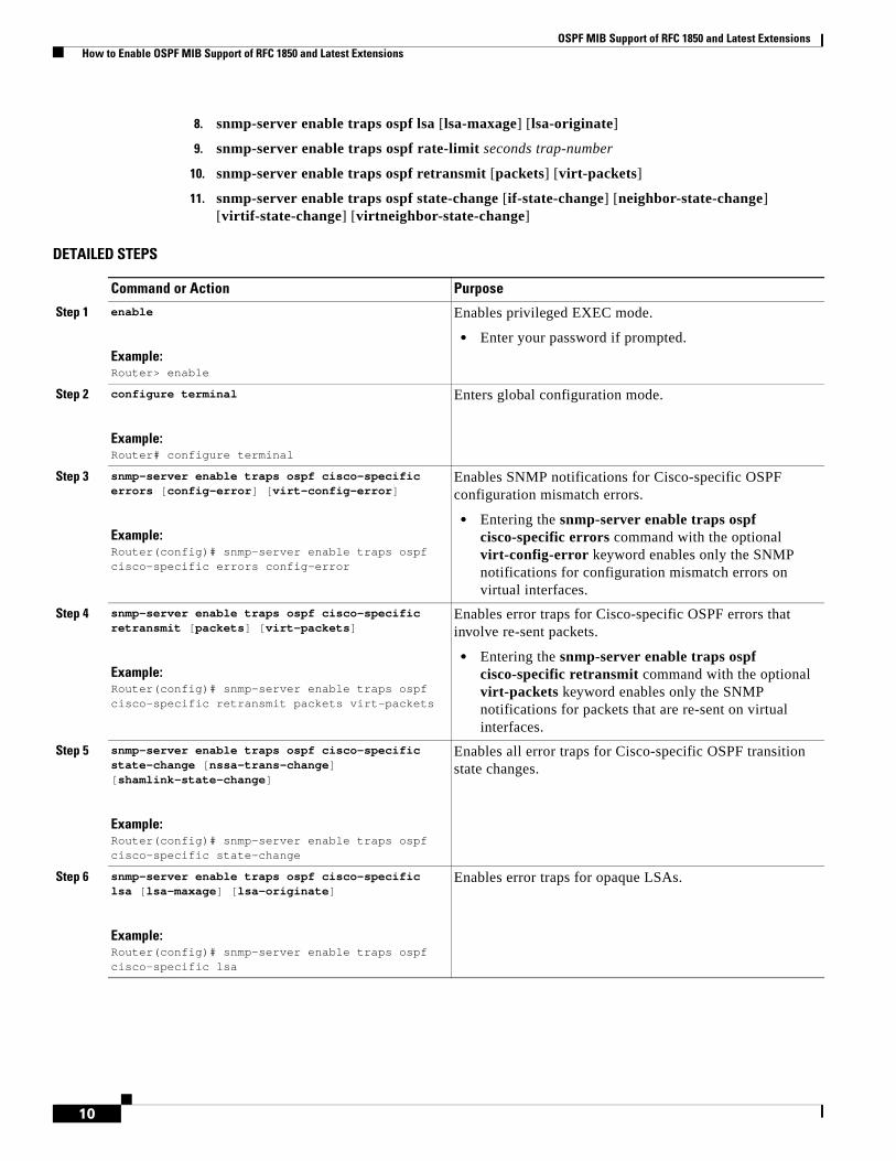
OSPF MIB Support of RFC 1850 and Latest Extensions How to Enable OSPF MIB Support of RFC 1850 and Latest Extensions
10
8. snmp-server enable traps ospf lsa [lsa-maxage] [lsa-originate]
9. snmp-server enable traps ospf rate-limit seconds trap-number
10. snmp-server enable traps ospf retransmit [packets] [virt-packets]
11. snmp-server enable traps ospf state-change [if-state-change] [neighbor-state-change] [virtif-state-change] [virtneighbor-state-change]
DETAILED STEPS
Command or Action Purpose
Step 1 enable
Example:Router> enable
Enables privileged EXEC mode.
• Enter your password if prompted.
Step 2 configure terminal
Example:Router# configure terminal
Enters global configuration mode.
Step 3 snmp-server enable traps ospf cisco-specific errors [config-error] [virt-config-error]
Example:Router(config)# snmp-server enable traps ospf cisco-specific errors config-error
Enables SNMP notifications for Cisco-specific OSPF configuration mismatch errors.
• Entering the snmp-server enable traps ospf cisco-specific errors command with the optional virt-config-error keyword enables only the SNMP notifications for configuration mismatch errors on virtual interfaces.
Step 4 snmp-server enable traps ospf cisco-specific retransmit [packets] [virt-packets]
Example:Router(config)# snmp-server enable traps ospf cisco-specific retransmit packets virt-packets
Enables error traps for Cisco-specific OSPF errors that involve re-sent packets.
• Entering the snmp-server enable traps ospf cisco-specific retransmit command with the optional virt-packets keyword enables only the SNMP notifications for packets that are re-sent on virtual interfaces.
Step 5 snmp-server enable traps ospf cisco-specific state-change [nssa-trans-change] [shamlink-state-change]
Example:Router(config)# snmp-server enable traps ospf cisco-specific state-change
Enables all error traps for Cisco-specific OSPF transition state changes.
Step 6 snmp-server enable traps ospf cisco-specific lsa [lsa-maxage] [lsa-originate]
Example:Router(config)# snmp-server enable traps ospf cisco-specific lsa
Enables error traps for opaque LSAs.
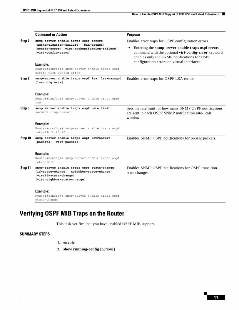
OSPF MIB Support of RFC 1850 and Latest Extensions How to Enable OSPF MIB Support of RFC 1850 and Latest Extensions
11
Verifying OSPF MIB Traps on the RouterThis task verifies that you have enabled OSPF MIB support.
SUMMARY STEPS
1. enable
2. show running-config [options]
Step 7 snmp-server enable traps ospf errors [authentication-failure] [bad-packet] [config-error] [virt-authentication-failure] [virt-config-error]
Example:Router(config)# snmp-server enable traps ospf errors virt-config-error
Enables error traps for OSPF configuration errors.
• Entering the snmp-server enable traps ospf errors command with the optional virt-config-error keyword enables only the SNMP notifications for OSPF configuration errors on virtual interfaces.
Step 8 snmp-server enable traps ospf lsa [lsa-maxage] [lsa-originate]
Example:Router(config)# snmp-server enable traps ospf lsa
Enables error traps for OSPF LSA errors.
Step 9 snmp-server enable traps ospf rate-limit seconds trap-number
Example:Router(config)# snmp-server enable traps ospf rate-limit 20 20
Sets the rate limit for how many SNMP OSPF notifications are sent in each OSPF SNMP notification rate-limit window.
Step 10 snmp-server enable traps ospf retransmit [packets] [virt-packets]
Example:Router(config)# snmp-server enable traps ospf retransmit
Enables SNMP OSPF notifications for re-sent packets.
Step 11 snmp-server enable traps ospf state-change [if-state-change] [neighbor-state-change] [virtif-state-change] [virtneighbor-state-change]
Example:Router(config)# snmp-server enable traps ospf state-change
Enables SNMP OSPF notifications for OSPF transition state changes.
Command or Action Purpose
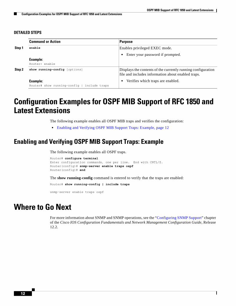
OSPF MIB Support of RFC 1850 and Latest Extensions Configuration Examples for OSPF MIB Support of RFC 1850 and Latest Extensions
12
DETAILED STEPS
Configuration Examples for OSPF MIB Support of RFC 1850 and Latest Extensions
The following example enables all OSPF MIB traps and verifies the configuration:
• Enabling and Verifying OSPF MIB Support Traps: Example, page 12
Enabling and Verifying OSPF MIB Support Traps: ExampleThe following example enables all OSPF traps.
Router# configure terminalEnter configuration commands, one per line. End with CNTL/Z.Router(config)# snmp-server enable traps ospfRouter(config)# end
The show running-config command is entered to verify that the traps are enabled:
Router# show running-config | include traps
snmp-server enable traps ospf
Where to Go NextFor more information about SNMP and SNMP operations, see the “Configuring SNMP Support” chapter of the Cisco IOS Configuration Fundamentals and Network Management Configuration Guide, Release 12.2.
Command or Action Purpose
Step 1 enable
Example:Router> enable
Enables privileged EXEC mode.
• Enter your password if prompted.
Step 2 show running-config [options]
Example:Router# show running-config | include traps
Displays the contents of the currently running configuration file and includes information about enabled traps.
• Verifies which traps are enabled.
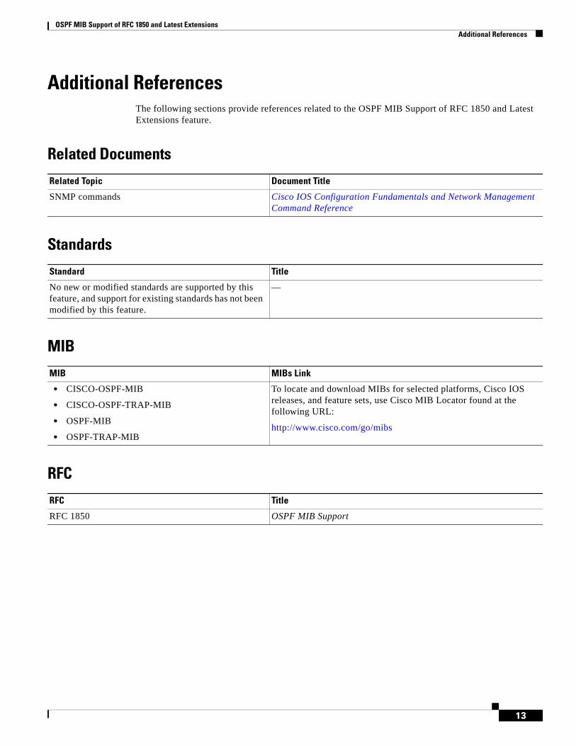
OSPF MIB Support of RFC 1850 and Latest Extensions Additional References
13
Additional ReferencesThe following sections provide references related to the OSPF MIB Support of RFC 1850 and Latest Extensions feature.
Related Documents
Standards
MIB
RFC
Related Topic Document Title
SNMP commands Cisco IOS Configuration Fundamentals and Network Management Command Reference
Standard Title
No new or modified standards are supported by this feature, and support for existing standards has not been modified by this feature.
—
MIB MIBs Link
• CISCO-OSPF-MIB
• CISCO-OSPF-TRAP-MIB
• OSPF-MIB
• OSPF-TRAP-MIB
To locate and download MIBs for selected platforms, Cisco IOS releases, and feature sets, use Cisco MIB Locator found at the following URL:
http://www.cisco.com/go/mibs
RFC Title
RFC 1850 OSPF MIB Support

OSPF MIB Support of RFC 1850 and Latest Extensions Command Reference
14
Technical Assistance
Command ReferenceThe following commands are introduced or modified in the feature or features documented in this module. For information about these commands, see the Cisco IOS IP Routing: OSPF Command Reference. For information about all Cisco IOS commands, go to the Command Lookup Tool at http://tools.cisco.com/Support/CLILookup or to the Cisco IOS Master Commands List.
• snmp-server enable traps ospf
• snmp-server enable traps ospf cisco-specific errors
• snmp-server enable traps ospf cisco-specific lsa
• snmp-server enable traps ospf cisco-specific retransmit
• snmp-server enable traps ospf cisco-specific state-change
• snmp-server enable traps ospf errors
• snmp-server enable traps ospf lsa
• snmp-server enable traps ospf rate-limit
• snmp-server enable traps ospf retransmit
• snmp-server enable traps ospf state-change
Feature Information for OSPF MIB Support of RFC 1850 and Latest Extensions
Table 5 lists the release history for this feature.
Not all commands may be available in your Cisco IOS software release. For release information about a specific command, see the command reference documentation.
Use Cisco Feature Navigator to find information about platform support and software image support. Cisco Feature Navigator enables you to determine which Cisco IOS and Catalyst OS software images support a specific software release, feature set, or platform. To access Cisco Feature Navigator, go to http://www.cisco.com/go/cfn. An account on Cisco.com is not required.
Note Table 5 lists only the Cisco IOS software release that introduced support for a given feature in a given Cisco IOS software release train. Unless noted otherwise, subsequent releases of that Cisco IOS software release train also support that feature.
Description Link
The Cisco Technical Support & Documentation website contains thousands of pages of searchable technical content, including links to products, technologies, solutions, technical tips, tools, and technical documentation. Registered Cisco.com users can log in from this page to access even more content.
http://www.cisco.com/techsupport
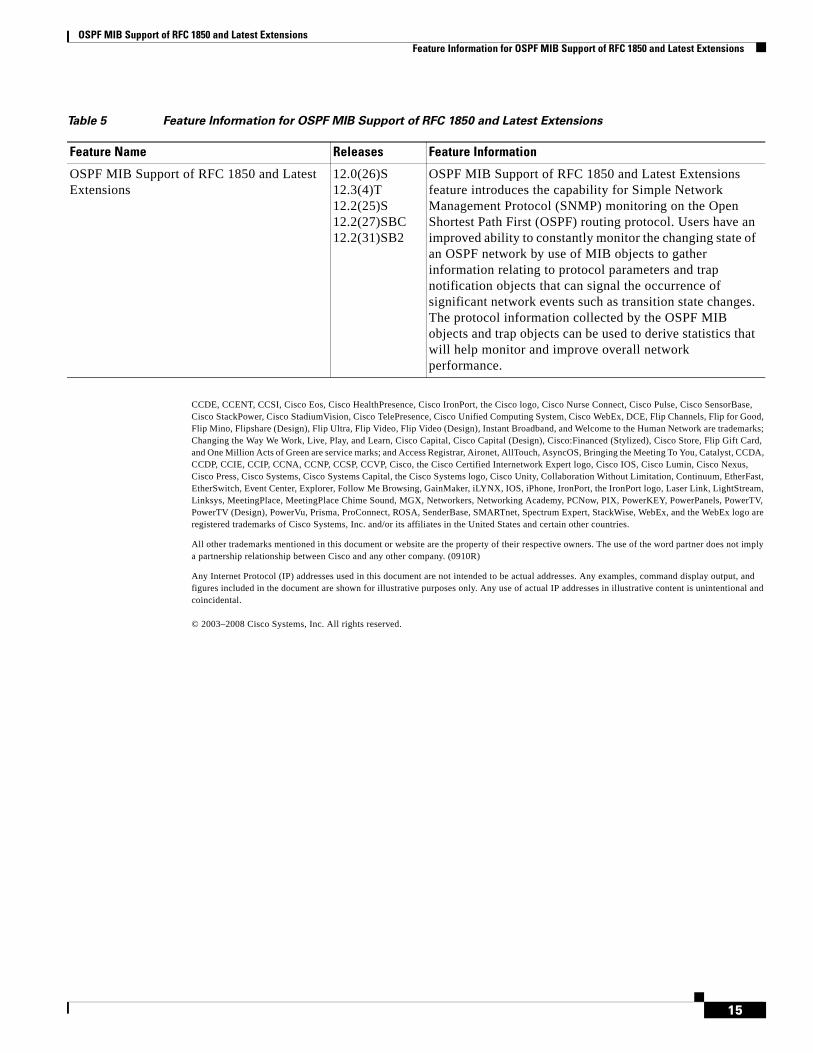
OSPF MIB Support of RFC 1850 and Latest Extensions Feature Information for OSPF MIB Support of RFC 1850 and Latest Extensions
15
CCDE, CCENT, CCSI, Cisco Eos, Cisco HealthPresence, Cisco IronPort, the Cisco logo, Cisco Nurse Connect, Cisco Pulse, Cisco SensorBase, Cisco StackPower, Cisco StadiumVision, Cisco TelePresence, Cisco Unified Computing System, Cisco WebEx, DCE, Flip Channels, Flip for Good, Flip Mino, Flipshare (Design), Flip Ultra, Flip Video, Flip Video (Design), Instant Broadband, and Welcome to the Human Network are trademarks; Changing the Way We Work, Live, Play, and Learn, Cisco Capital, Cisco Capital (Design), Cisco:Financed (Stylized), Cisco Store, Flip Gift Card, and One Million Acts of Green are service marks; and Access Registrar, Aironet, AllTouch, AsyncOS, Bringing the Meeting To You, Catalyst, CCDA, CCDP, CCIE, CCIP, CCNA, CCNP, CCSP, CCVP, Cisco, the Cisco Certified Internetwork Expert logo, Cisco IOS, Cisco Lumin, Cisco Nexus, Cisco Press, Cisco Systems, Cisco Systems Capital, the Cisco Systems logo, Cisco Unity, Collaboration Without Limitation, Continuum, EtherFast, EtherSwitch, Event Center, Explorer, Follow Me Browsing, GainMaker, iLYNX, IOS, iPhone, IronPort, the IronPort logo, Laser Link, LightStream, Linksys, MeetingPlace, MeetingPlace Chime Sound, MGX, Networkers, Networking Academy, PCNow, PIX, PowerKEY, PowerPanels, PowerTV, PowerTV (Design), PowerVu, Prisma, ProConnect, ROSA, SenderBase, SMARTnet, Spectrum Expert, StackWise, WebEx, and the WebEx logo are registered trademarks of Cisco Systems, Inc. and/or its affiliates in the United States and certain other countries.
All other trademarks mentioned in this document or website are the property of their respective owners. The use of the word partner does not imply a partnership relationship between Cisco and any other company. (0910R)
Any Internet Protocol (IP) addresses used in this document are not intended to be actual addresses. Any examples, command display output, and figures included in the document are shown for illustrative purposes only. Any use of actual IP addresses in illustrative content is unintentional and coincidental.
© 2003–2008 Cisco Systems, Inc. All rights reserved.
Table 5 Feature Information for OSPF MIB Support of RFC 1850 and Latest Extensions
Feature Name Releases Feature Information
OSPF MIB Support of RFC 1850 and Latest Extensions
12.0(26)S12.3(4)T12.2(25)S12.2(27)SBC12.2(31)SB2
OSPF MIB Support of RFC 1850 and Latest Extensions feature introduces the capability for Simple Network Management Protocol (SNMP) monitoring on the Open Shortest Path First (OSPF) routing protocol. Users have an improved ability to constantly monitor the changing state of an OSPF network by use of MIB objects to gather information relating to protocol parameters and trap notification objects that can signal the occurrence of significant network events such as transition state changes. The protocol information collected by the OSPF MIB objects and trap objects can be used to derive statistics that will help monitor and improve overall network performance.

OSPF MIB Support of RFC 1850 and Latest Extensions Feature Information for OSPF MIB Support of RFC 1850 and Latest Extensions
16
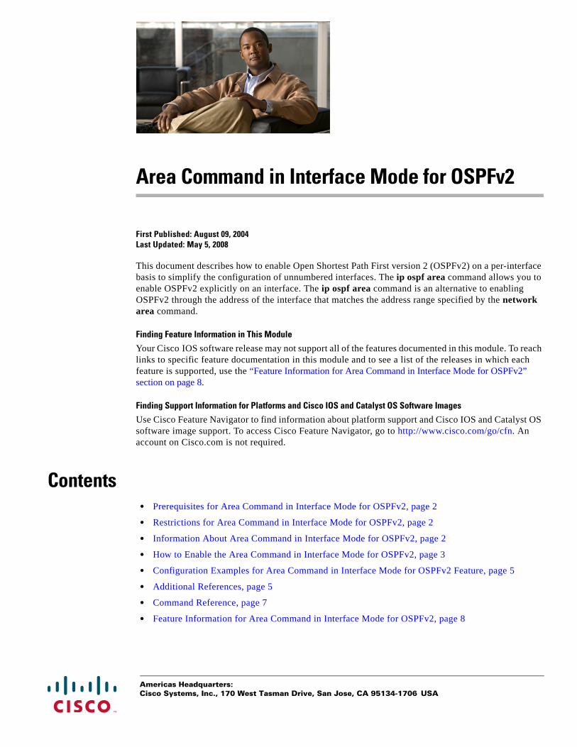
Americas Headquarters:Cisco Systems, Inc., 170 West Tasman Drive, San Jose, CA 95134-1706 USA
Area Command in Interface Mode for OSPFv2
First Published: August 09, 2004Last Updated: May 5, 2008
This document describes how to enable Open Shortest Path First version 2 (OSPFv2) on a per-interface basis to simplify the configuration of unnumbered interfaces. The ip ospf area command allows you to enable OSPFv2 explicitly on an interface. The ip ospf area command is an alternative to enabling OSPFv2 through the address of the interface that matches the address range specified by the network area command.
Finding Feature Information in This Module
Your Cisco IOS software release may not support all of the features documented in this module. To reach links to specific feature documentation in this module and to see a list of the releases in which each feature is supported, use the “Feature Information for Area Command in Interface Mode for OSPFv2” section on page 8.
Finding Support Information for Platforms and Cisco IOS and Catalyst OS Software Images
Use Cisco Feature Navigator to find information about platform support and Cisco IOS and Catalyst OS software image support. To access Cisco Feature Navigator, go to http://www.cisco.com/go/cfn. An account on Cisco.com is not required.
Contents• Prerequisites for Area Command in Interface Mode for OSPFv2, page 2
• Restrictions for Area Command in Interface Mode for OSPFv2, page 2
• Information About Area Command in Interface Mode for OSPFv2, page 2
• How to Enable the Area Command in Interface Mode for OSPFv2, page 3
• Configuration Examples for Area Command in Interface Mode for OSPFv2 Feature, page 5
• Additional References, page 5
• Command Reference, page 7
• Feature Information for Area Command in Interface Mode for OSPFv2, page 8
Area Command in Interface Mode for OSPFv2 Prerequisites for Area Command in Interface Mode for OSPFv2
2
Prerequisites for Area Command in Interface Mode for OSPFv2OSPFv2 must be running on your network.
Restrictions for Area Command in Interface Mode for OSPFv2The ip ospf area command is supported only for OSPFv2.
Information About Area Command in Interface Mode for OSPFv2This section contains the following information:
• Benefits of Area Command in Interface Mode for OSPFv2 Feature, page 2
• Configuration Guidelines for the Area Command in Interface Mode for OSPFv2 Feature, page 2
Benefits of Area Command in Interface Mode for OSPFv2 FeatureOSPF is enabled on an interface when the network address for the interface matches the range of addresses that is specified by the network area command that is entered in router configuration mode. You can enable OSPFv2 explicitly on an interface with the ip ospf area command that is entered in interface configuration mode. This capability simplifies the configuration of unnumbered interfaces with different areas.
Because the ip ospf area command is configured explicitly for an interface, it will supersede the effects of the network area command that is entered at the network level to affect the interfaces whose addresses fall within the address range specified for the network area command.
If you later disable the ip ospf area command, the interface still will run OSPFv2 as long as its network address matches the range of addresses that is specified by the network area command.
Configuration Guidelines for the Area Command in Interface Mode for OSPFv2 Feature
When you use the ip ospf area command in interface configuration mode to enable OSPFv2 on an interface, we recommend that you be familiar with the following guidelines.
Interface Is Already OSPFv2-Enabled by network area Command with Same Area and Process
If you enter the ip ospf area command on an interface that is enabled in OSPFv2 by the network area command, the process ID or area ID of the interface does not change, and the interface status will not be changed. However, the interface will be flagged as being configured from interface configuration mode and the configuration data will be saved in the interface description block (IDB).

Area Command in Interface Mode for OSPFv2 How to Enable the Area Command in Interface Mode for OSPFv2
3
Interface Is Already Configured by network area Command with Different Area or Process
If you enter the ip ospf area command on an interface that is enabled in OSPFv2 by the network area command, but change the configuration by changing the process ID and area ID of the interface, after the new configuration information is stored in the IDB, the interface will be removed and reattached. Therefore, the interface will be removed from the original area and process and be added to the new ones. The state of the interface will also be reset.
Interface Is Not Configured by network area Command
If the interface is not enabled in OSPFv2 by the network area command, the area and OSPF router instance will be created if needed. When the router is reloaded, the OSPF process will not begin running until system initialization is complete. To remove an OSPF router instance, enter the no router ospf command. Removing the ip ospf area command in interface mode will not result in removing an OSPF router instance.
Removing an interface enable Command
When the interface enable command is removed, the interface will be detached from the area. The area will be removed if it has no other attached interfaces. If the interface address is covered by the network area command, the interface will be enabled once again in the area for the network that it is in.
New Processes
If an OSPF process does not already exist, and a router ID cannot be chosen when either the router ospf command or the interface command is configured, a Proximity Database (PDB) and a process will be created, but the process will be inactive. The process will become active when a router ID is chosen, either when it is explicitly configured using the router-id command or when an IP address becomes available. Note that the router ospf command will now be accepted even if a router ID cannot be chosen, putting the command-line interface (CLI) into the OSPF configuration context. Therefore, the router-id command is to be entered before an IP address is available. If the process is not active and the show ip ospf command is entered, the message “%OSPF: Router process X is not running, please provide a router-id” will be displayed.
Link-State Advertisements and Shortest Path First
If a state change occurs as a result of the interface enable command, new router link-state advertisements (LSAs) will be generated (also for the old area, if the interface is changing areas) and shortest path first (SPF) will be scheduled to run in both the old and new areas.
How to Enable the Area Command in Interface Mode for OSPFv2This section contains the following procedure:
• Enabling OSPFv2 on an Interface, page 3 (required)
Enabling OSPFv2 on an InterfacePerform this task to enable OSPFv2 on an interface.
SUMMARY STEPS
1. enable
2. configure terminal
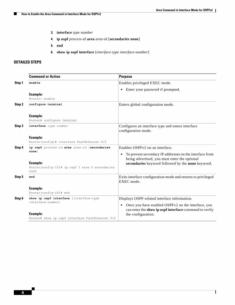
Area Command in Interface Mode for OSPFv2 How to Enable the Area Command in Interface Mode for OSPFv2
4
3. interface type number
4. ip ospf process-id area area-id [secondaries none]
5. end
6. show ip ospf interface [interface-type interface-number]
DETAILED STEPS
Command or Action Purpose
Step 1 enable
Example:Router> enable
Enables privileged EXEC mode.
• Enter your password if prompted.
Step 2 configure terminal
Example:Router# configure terminal
Enters global configuration mode.
Step 3 interface type number
Example:Router(config)# interface FastEthernet 0/2
Configures an interface type and enters interface configuration mode.
Step 4 ip ospf process-id area area-id [secondaries none]
Example:Router(config-if)# ip ospf 1 area 0 secondaries none
Enables OSPFv2 on an interface.
• To prevent secondary IP addresses on the interface from being advertised, you must enter the optional secondaries keyword followed by the none keyword.
Step 5 end
Example:Router(config-if)# end
Exits interface configuration mode and returns to privileged EXEC mode.
Step 6 show ip ospf interface [interface-type interface-number]
Example:Router# show ip ospf interface FastEthernet 0/2
Displays OSPF-related interface information.
• Once you have enabled OSPFv2 on the interface, you can enter the show ip ospf interface command to verify the configuration.
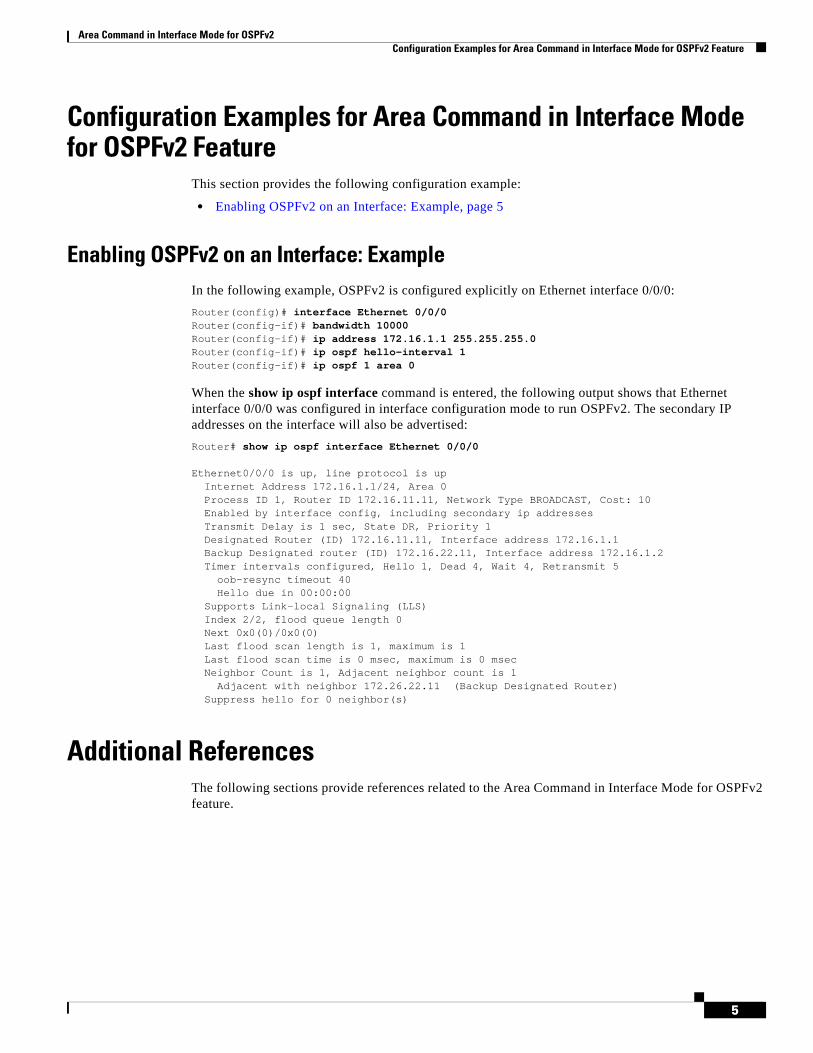
Area Command in Interface Mode for OSPFv2 Configuration Examples for Area Command in Interface Mode for OSPFv2 Feature
5
Configuration Examples for Area Command in Interface Mode for OSPFv2 Feature
This section provides the following configuration example:
• Enabling OSPFv2 on an Interface: Example, page 5
Enabling OSPFv2 on an Interface: ExampleIn the following example, OSPFv2 is configured explicitly on Ethernet interface 0/0/0:
Router(config)# interface Ethernet 0/0/0Router(config-if)# bandwidth 10000Router(config-if)# ip address 172.16.1.1 255.255.255.0Router(config-if)# ip ospf hello-interval 1Router(config-if)# ip ospf 1 area 0
When the show ip ospf interface command is entered, the following output shows that Ethernet interface 0/0/0 was configured in interface configuration mode to run OSPFv2. The secondary IP addresses on the interface will also be advertised:
Router# show ip ospf interface Ethernet 0/0/0
Ethernet0/0/0 is up, line protocol is up Internet Address 172.16.1.1/24, Area 0 Process ID 1, Router ID 172.16.11.11, Network Type BROADCAST, Cost: 10Enabled by interface config, including secondary ip addressesTransmit Delay is 1 sec, State DR, Priority 1 Designated Router (ID) 172.16.11.11, Interface address 172.16.1.1Backup Designated router (ID) 172.16.22.11, Interface address 172.16.1.2Timer intervals configured, Hello 1, Dead 4, Wait 4, Retransmit 5
oob-resync timeout 40Hello due in 00:00:00
Supports Link-local Signaling (LLS)Index 2/2, flood queue length 0Next 0x0(0)/0x0(0)Last flood scan length is 1, maximum is 1Last flood scan time is 0 msec, maximum is 0 msecNeighbor Count is 1, Adjacent neighbor count is 1
Adjacent with neighbor 172.26.22.11 (Backup Designated Router)Suppress hello for 0 neighbor(s)
Additional ReferencesThe following sections provide references related to the Area Command in Interface Mode for OSPFv2 feature.
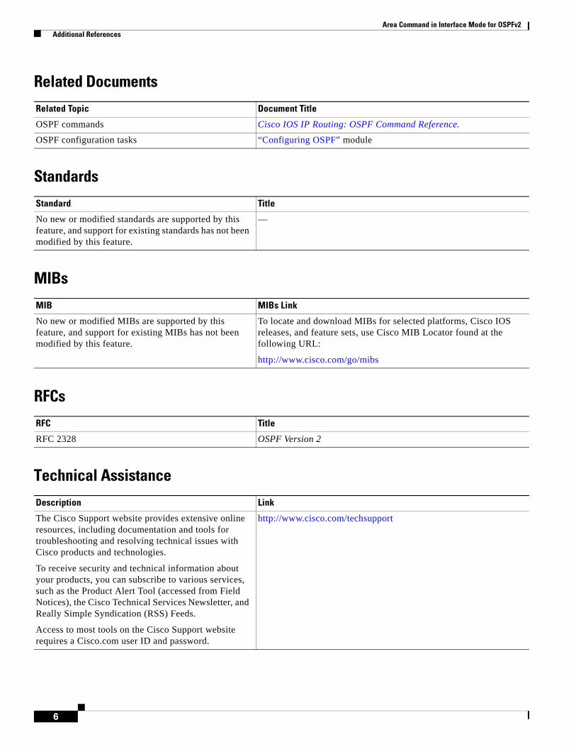
Area Command in Interface Mode for OSPFv2 Additional References
6
Related Documents
Standards
MIBs
RFCs
Technical Assistance
Related Topic Document Title
OSPF commands Cisco IOS IP Routing: OSPF Command Reference.
OSPF configuration tasks “Configuring OSPF” module
Standard Title
No new or modified standards are supported by this feature, and support for existing standards has not been modified by this feature.
—
MIB MIBs Link
No new or modified MIBs are supported by this feature, and support for existing MIBs has not been modified by this feature.
To locate and download MIBs for selected platforms, Cisco IOS releases, and feature sets, use Cisco MIB Locator found at the following URL:
http://www.cisco.com/go/mibs
RFC Title
RFC 2328 OSPF Version 2
Description Link
The Cisco Support website provides extensive online resources, including documentation and tools for troubleshooting and resolving technical issues with Cisco products and technologies.
To receive security and technical information about your products, you can subscribe to various services, such as the Product Alert Tool (accessed from Field Notices), the Cisco Technical Services Newsletter, and Really Simple Syndication (RSS) Feeds.
Access to most tools on the Cisco Support website requires a Cisco.com user ID and password.
http://www.cisco.com/techsupport

Area Command in Interface Mode for OSPFv2 Command Reference
7
Command ReferenceThe following commands are introduced or modified in the feature or features documented in this module. For information about these commands, see the Cisco IOS IP Routing: OSPF Command Reference. For information about all Cisco IOS commands, go to the Command Lookup Tool at http://tools.cisco.com/Support/CLILookup or to the Cisco IOS Master Commands List.
• ip ospf area
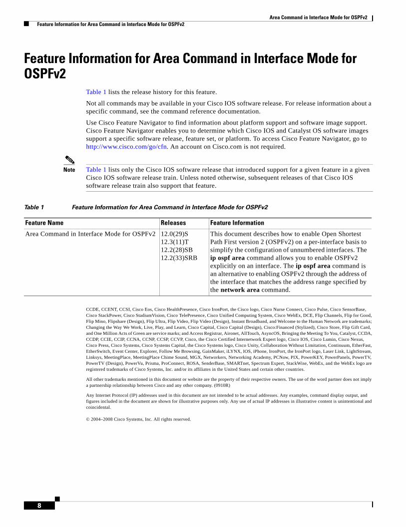
Area Command in Interface Mode for OSPFv2 Feature Information for Area Command in Interface Mode for OSPFv2
8
Feature Information for Area Command in Interface Mode for OSPFv2
Table 1 lists the release history for this feature.
Not all commands may be available in your Cisco IOS software release. For release information about a specific command, see the command reference documentation.
Use Cisco Feature Navigator to find information about platform support and software image support. Cisco Feature Navigator enables you to determine which Cisco IOS and Catalyst OS software images support a specific software release, feature set, or platform. To access Cisco Feature Navigator, go to http://www.cisco.com/go/cfn. An account on Cisco.com is not required.
Note Table 1 lists only the Cisco IOS software release that introduced support for a given feature in a given Cisco IOS software release train. Unless noted otherwise, subsequent releases of that Cisco IOS software release train also support that feature.
CCDE, CCENT, CCSI, Cisco Eos, Cisco HealthPresence, Cisco IronPort, the Cisco logo, Cisco Nurse Connect, Cisco Pulse, Cisco SensorBase, Cisco StackPower, Cisco StadiumVision, Cisco TelePresence, Cisco Unified Computing System, Cisco WebEx, DCE, Flip Channels, Flip for Good, Flip Mino, Flipshare (Design), Flip Ultra, Flip Video, Flip Video (Design), Instant Broadband, and Welcome to the Human Network are trademarks; Changing the Way We Work, Live, Play, and Learn, Cisco Capital, Cisco Capital (Design), Cisco:Financed (Stylized), Cisco Store, Flip Gift Card, and One Million Acts of Green are service marks; and Access Registrar, Aironet, AllTouch, AsyncOS, Bringing the Meeting To You, Catalyst, CCDA, CCDP, CCIE, CCIP, CCNA, CCNP, CCSP, CCVP, Cisco, the Cisco Certified Internetwork Expert logo, Cisco IOS, Cisco Lumin, Cisco Nexus, Cisco Press, Cisco Systems, Cisco Systems Capital, the Cisco Systems logo, Cisco Unity, Collaboration Without Limitation, Continuum, EtherFast, EtherSwitch, Event Center, Explorer, Follow Me Browsing, GainMaker, iLYNX, IOS, iPhone, IronPort, the IronPort logo, Laser Link, LightStream, Linksys, MeetingPlace, MeetingPlace Chime Sound, MGX, Networkers, Networking Academy, PCNow, PIX, PowerKEY, PowerPanels, PowerTV, PowerTV (Design), PowerVu, Prisma, ProConnect, ROSA, SenderBase, SMARTnet, Spectrum Expert, StackWise, WebEx, and the WebEx logo are registered trademarks of Cisco Systems, Inc. and/or its affiliates in the United States and certain other countries.
All other trademarks mentioned in this document or website are the property of their respective owners. The use of the word partner does not imply a partnership relationship between Cisco and any other company. (0910R)
Any Internet Protocol (IP) addresses used in this document are not intended to be actual addresses. Any examples, command display output, and figures included in the document are shown for illustrative purposes only. Any use of actual IP addresses in illustrative content is unintentional and coincidental.
© 2004–2008 Cisco Systems, Inc. All rights reserved.
Table 1 Feature Information for Area Command in Interface Mode for OSPFv2
Feature Name Releases Feature Information
Area Command in Interface Mode for OSPFv2 12.0(29)S12.3(11)T12.2(28)SB12.2(33)SRB
This document describes how to enable Open Shortest Path First version 2 (OSPFv2) on a per-interface basis to simplify the configuration of unnumbered interfaces. The ip ospf area command allows you to enable OSPFv2 explicitly on an interface. The ip ospf area command is an alternative to enabling OSPFv2 through the address of the interface that matches the address range specified by the network area command.