nt series - beyma€¦ · componentes convergen en un producto idóneo para multitud de...
TRANSCRIPT
NT SERIES
NT12P / NT15P NT12A250 / NT15A250 NT12A500 / NT15A500
AMATE ELECTROACÚSTICA,S.L
Pol.Ind.Norte-Perpinyà,25 08226 TERRASSA (Barcelona-SPAIN)
www. master-audio.com
Manual de usuario / User's guide
Mayo 07 / May 07
ESPAÑOL
Instrucciones de seguridad 1. Todas las instrucciones de seguridad deben
ser leídas antes de utilizar este aparato.
2. El signo de exclamación dentro de un
triángulo indica componentes internos cuyo
reemplazo puede afectar la seguridad.
3. El símbolo del rayo con la punta de la flecha
indica la presencia de voltajes peligrosos no
aislados.
4. Este equipo no debe ser expuesto a la lluvia
ni a la humedad. No lo use, por ejemplo, cerca
de piscinas, fuentes o cualquier lugar donde
pueda ser afectado por líquidos.
5. Limpie el aparato sólo con paños secos.
6. No sitúe el equipo en lugares donde se
interfiera la ventilación del aparato.
7. No instale el aparato cerca de ninguna fuente
de calor, como radiadores, estufas u otros
aparatos que emitan calor.
8. Este equipo debe ser reparado por personal
cualificado del servicio técnico cuando:
A. El cable de red esté dañado, o
B. Algún objeto o liquido haya dañado el
aparato; o
C. El equipo no funcione de una manera
normal (correcta); o
D. El equipo se haya expuesto a la lluvia; o
E. El chasis esté dañado
9. Desconecte el aparato en caso de tormentas
eléctricas o cuando no vaya a emplearlo
durante largos períodos de tiempo.
10. No cuelgue el equipo por el asa.
ENGLISH
Safety Instructions
1. All the safety and operation instructions
should be read before this product is operated.
2. The exclamation point within an equilateral
triangle is intended to alert the user of the
presence of internal components whose
substitution may affect safety.
3. The lightning flash with arrowhead symbol
within an equilateral triangle is intended to
alert the user of the presence of uninsulated
dangerous voltage that may constitute a risk of
electric shock to persons.
4. This product should not be exposed to rain
or moisture. Do not use it, for example, near a
swimming pool, water fountain or any liquid
sources.
5. Clean only with a dry cloth.
6. This product should be situated so that its
location does not interfere with its proper
ventilation.
7. Do not install near heat sources such as
radiators or other devices which produce heat.
8. This equipment should be serviced only by
qualified service personnel when:
A. The power-supply cord or the plug has
been damaged; or
B. Objects have fallen, or liquid has spilled;
or
C. This product does not appear to operate
normally; or
D. This product has been exposed to rain; or
E. The chassis is damaged.
9. Unplug this product during lightning storms
or when unused for long periods of time.
10. Do not suspend the cabinet from the handle
CAUTIONRISK OF ELECTRIC SHOCK
DON’T OPEN
To reduce the risk of fire or electric shock do not expose this equipment to rain or moisture
WARNING:
Amate Electroacústica,s.l.
NT Series.Version 1.0 May 07 3
1.INTRODUCCIÓN 1.1. Generalidades Amate Electroacústica, s.l. le agradece la
confianza depositada en nuestros productos de la Serie NT.
La experiencia de más de 30 años en el diseño de cajas acústicas y amplificadores
y la utilización de la más alta tecnología y componentes convergen en un producto
idóneo para multitud de aplicaciones, tanto en instalaciones fijas como sonorización en directo. Le sugerimos lea atentamente las
indicaciones que a continuación exponemos, confiando en que le serán de gran utilidad para obtener sus mejores
resultados.
1.2. Características y presentación NT-12P
- Sistema de 2 vías Full Range.
- Incorpora filtro divisor pasivo diseñado con precisión para obtener los mejores resultados.
- Altavoz de 12" y alto rendimiento. - Motor de agudos con diafragma de Titanio
de 1" ½. - Capacidad de Potencia de 250W r.m.s
- Sensibilidad de 98 dB (1W/1m). NT-15P
- Sistema de 2 vías Full Range.
- Incorpora filtro divisor pasivo diseñado con precisión para obtener los mejores resultados.
- Altavoz de 15" y alto rendimiento. - Motor de agudos con diafragma de Titanio
de 1" ½. - Capacidad de Potencia de 250W r.m.s
- Sensibilidad de 99 dB (1W/1m).
1. INTRODUCTION 1.1. General Amate Electroacústica, s.l. would like to
thank you for your confidence in our NT Series.
A gathered experience of more than 30 years in the design of acoustic cabinets and
amplifiers, together with the application of the most advanced analysis devices have allowed the NT Series become the optimal
and ideal solution for fixed installations and especially for live events.
We suggest you to carefully read the
following instructions in order to obtain the best results in performance.
1.2. Features and presentation
NT-12P
- Two Way Full Range Speaker System. - Passive version with an accurate designed
Crossover to achieve the best performance. - 12" High Performance Woofer. - 1" ½ Titanium diaphragm Driver.
- Power Handling: 250W r.m.s. - Sensitivity : 98 dB (1W/1m).
NT-15P
- Two Way Full Range Speaker System. - Passive version with an accurate designed
Crossover to achieve the best performance. - 15" High Performance Woofer. - 1" ½ Titanium diaphragm Driver.
- Power Handling: 250W r.m.s. - Sensitivity : 99 dB (1W/1m).
Amate Electroacústica,s.l.
NT Series.Version 1.0 May 07 4
NT-12A250
- Entrada balanceada electrónicamente (XLR).
- Salida paralela con conector XLR.
- Divisor Activo de 24 dB/Oct.
- Amplificador Clase D de 200 W.
- Altavoz de 12" de alto rendimiento.
- Amplificador de Clase AB de 50 W.
- Motor de agudos con diafragma de Titanio
de 1" ½.
- Total procesamiento de señal con
limitadores de clipping.
NT-12A500
- Entrada balanceada electrónicamente (XLR).
- Salida paralela con conector XLR.
- Divisor Activo de 24 dB/Oct.
- Amplificador Clase D de 500 W.
- Altavoz de 12" de Neodimio y alto
rendimiento.
- Amplificador de Clase AB de 60 W.
- Motor de agudos con diafragma de Titanio
de 1" ½.
- Total procesamiento de señal con
limitadores de clipping.
NT-15A250
- Entrada balanceada electrónicamente (XLR).
- Salida paralela con conector XLR.
- Divisor Activo de 24 dB/Oct.
- Amplificador Clase D de 200 W.
- Altavoz de 15" de alto rendimiento.
- Amplificador de Clase AB de 50 W.
- Motor de agudos con diafragma de Titanio
de 1" ½.
- Total procesamiento de señal con
limitadores de clipping.
NT-15A500
- Entrada balanceada electrónicamente (XLR).
- Salida paralela con conector XLR.
- Divisor Activo de 24 dB/Oct.
- Amplificador Clase D de 500 W.
- Altavoz de 15" de alto rendimiento.
- Amplificador de Clase AB de 60 W.
- Motor de agudos con diafragma de Titanio
de 1" ½.
- Total procesamiento de señal con
limitadores de clipping.
NT-12A250
- Electronically balanced Input (XLR).
- XLR parallel output.
- 24dB/Oct Active Crossover.
- 200 W High Efficiency Class D Amplifier.
- 12" High Performance Woofer.
- 50 W Class AB Amplifier.
- 1" ½ Titanium diaphragm Driver.
- Full Signal Processing with active clip
limiters.
NT-12A500
- Electronically balanced Input (XLR).
- XLR parallel output.
- 24dB/Oct Active Crossover.
- 500 W High Efficiency Class D Amplifier.
- 12" High Performance Woofer.
- 60 W Class AB Amplifier.
- 1" ½ Titanium diaphragm Driver.
- Full Signal Processing with active clip
limiters.
NT-15A250
- Electronically balanced Input (XLR).
- XLR parallel output.
- 24dB/Oct Active Crossover.
- 200 W High Efficiency Class D Amplifier.
- 15" High Performance Woofer.
- 50 W Class AB Amplifier.
- 1" ½ Titanium diaphragm Driver.
- Full Signal Processing with active clip
limiters.
NT-15A500
- Electronically balanced Input (XLR).
- XLR parallel output.
- 24dB/Oct Active Crossover.
- 500 W High Efficiency Class D Amplifier.
- 15" High Performance Woofer.
- 60 W Class AB Amplifier.
- 1" ½ Titanium diaphragm Driver.
- Full Signal Processing with active clip
limiters.
Amate Electroacústica,s.l.
NT Series.Version 1.0 May 07 5
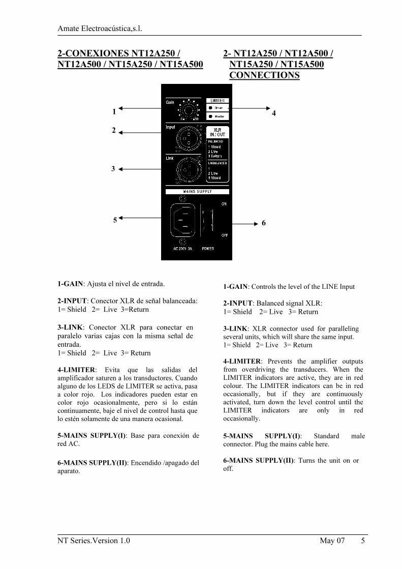
2-CONEXIONES NT12A250 / NT12A500 / NT15A250 / NT15A500 1 2 3
5 1-GAIN: Ajusta el nivel de entrada.
2-INPUT: Conector XLR de señal balanceada:
1= Shield 2= Live 3=Return 3-LINK: Conector XLR para conectar en
paralelo varias cajas con la misma señal de
entrada.
1= Shield 2= Live 3= Return
4-LIMITER: Evita que las salidas del
amplificador saturen a los transductores. Cuando
alguno de los LEDS de LIMITER se activa, pasa
a color rojo. Los indicadores pueden estar en
color rojo ocasionalmente, pero si lo están
continuamente, baje el nivel de control hasta que
lo estén solamente de una manera ocasional. 5-MAINS SUPPLY(I): Base para conexión de
red AC.
6-MAINS SUPPLY(II): Encendido /apagado del
aparato.
2- NT12A250 / NT12A500 / NT15A250 / NT15A500 CONNECTIONS
4
6
1-GAIN: Controls the level of the LINE Input
2-INPUT: Balanced signal XLR:
1= Shield 2= Live 3= Return
3-LINK: XLR connector used for paralleling
several units, which will share the same input.
1= Shield 2= Live 3= Return
4-LIMITER: Prevents the amplifier outputs
from overdriving the transducers. When the
LIMITER indicators are active, they are in red
colour. The LIMITER indicators can be in red
occasionally, but if they are continuously
activated, turn down the level control until the
LIMITER indicators are only in red
occasionally. 5-MAINS SUPPLY(I): Standard male
connector. Plug the mains cable here.
6-MAINS SUPPLY(II): Turns the unit on or
off.
Amate Electroacústica,s.l.
NT Series.Version 1.0 May 07 6
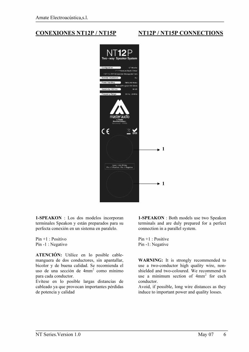
CONEXIONES NT12P / NT15P 1-SPEAKON : Los dos modelos incorporan
terminales Speakon y están preparados para su
perfecta conexión en un sistema en paralelo.
Pin +1 : Positivo
Pin -1 : Negativo
ATENCIÓN: Utilice en lo posible cable-
manguera de dos conductores, sin apantallar,
bicolor y de buena calidad. Se recomienda el
uso de una sección de 4mm2 como mínimo
para cada conductor.
Evítese en lo posible largas distancias de
cableado ya que provocan importantes pérdidas
de potencia y calidad
NT12P / NT15P CONNECTIONS 1 1 1-SPEAKON : Both models use two Speakon
terminals and are duly prepared for a perfect
connection in a parallel system.
Pin +1 : Positive
Pin -1: Negative
WARNING: It is strongly recommended to
use a two-conductor high quality wire, non-
shielded and two-coloured. We recommend to
use a minimum section of 4mm2 for each
conductor.
Avoid, if possible, long wire distances as they
induce to important power and quality losses.
Amate Electroacústica,s.l.
NT Series.Version 1.0 May 07 7
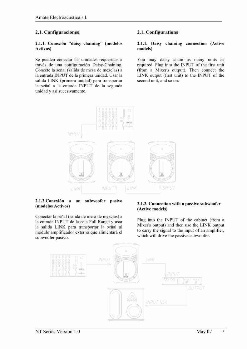
2.1. Configuraciones 2.1.1. Conexión "daisy chaining" (modelos Activos) Se pueden conectar las unidades requeridas a
través de una configuración Daisy-Chaining.
Conecte la señal (salida de mesa de mezclas) a
la entrada INPUT de la primera unidad. Usar la
salida LINK (primera unidad) para transportar
la señal a la entrada INPUT de la segunda
unidad y así sucesivamente.
2.1.2.Conexión a un subwoofer pasivo (modelos Activos)
Conectar la señal (salida de mesa de mezclas) a
la entrada INPUT de la caja Full Range y usar
la salida LINK para transportar la señal al
módulo amplificador externo que alimentará el
subwoofer pasivo.
2.1. Configurations 2.1.1. Daisy chaining connection (Active models) You may daisy chain as many units as
required. Plug into the INPUT of the first unit
(from a Mixer's output). Then connect the
LINK output (first unit) to the INPUT of the
second unit, and so on.
2.1.2. Connection with a passive subwoofer (Active models) Plug into the INPUT of the cabinet (from a
Mixer's output) and then use the LINK output
to carry the signal to the input of an amplifier,
which will drive the passive subwoofer.
Amate Electroacústica,s.l.
NT Series.Version 1.0 May 07 8
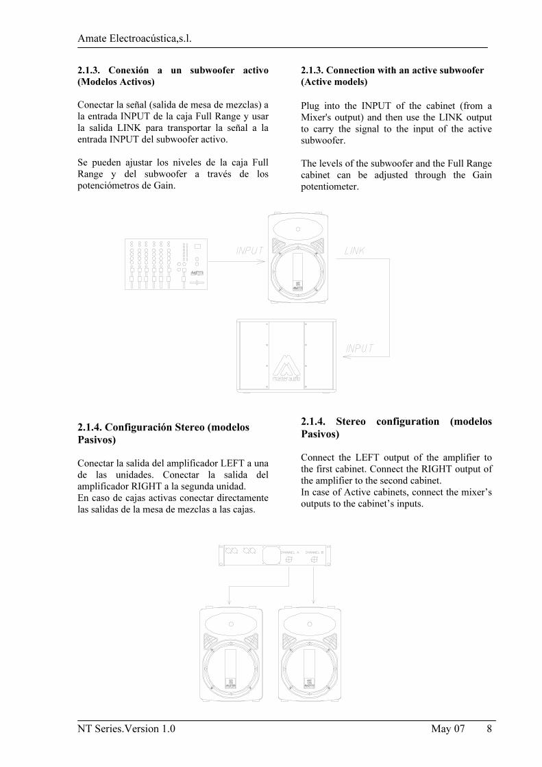
2.1.3. Conexión a un subwoofer activo (Modelos Activos)
Conectar la señal (salida de mesa de mezclas) a
la entrada INPUT de la caja Full Range y usar
la salida LINK para transportar la señal a la
entrada INPUT del subwoofer activo.
Se pueden ajustar los niveles de la caja Full
Range y del subwoofer a través de los
potenciómetros de Gain.
2.1.4. Configuración Stereo (modelos Pasivos)
Conectar la salida del amplificador LEFT a una
de las unidades. Conectar la salida del
amplificador RIGHT a la segunda unidad.
En caso de cajas activas conectar directamente
las salidas de la mesa de mezclas a las cajas.
2.1.3. Connection with an active subwoofer (Active models) Plug into the INPUT of the cabinet (from a
Mixer's output) and then use the LINK output
to carry the signal to the input of the active
subwoofer.
The levels of the subwoofer and the Full Range
cabinet can be adjusted through the Gain
potentiometer.
2.1.4. Stereo configuration (modelos Pasivos)
Connect the LEFT output of the amplifier to
the first cabinet. Connect the RIGHT output of
the amplifier to the second cabinet.
In case of Active cabinets, connect the mixer’s
outputs to the cabinet’s inputs.
Amate Electroacústica,s.l.
NT Series.Version 1.0 May 07 9
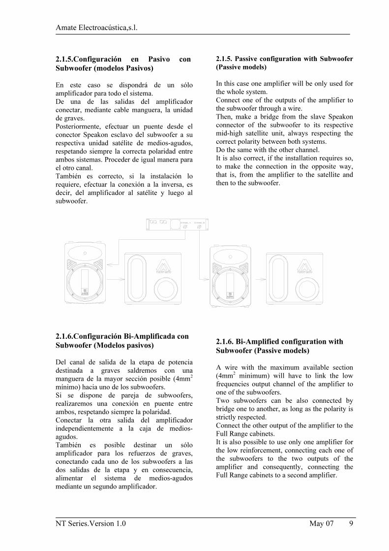
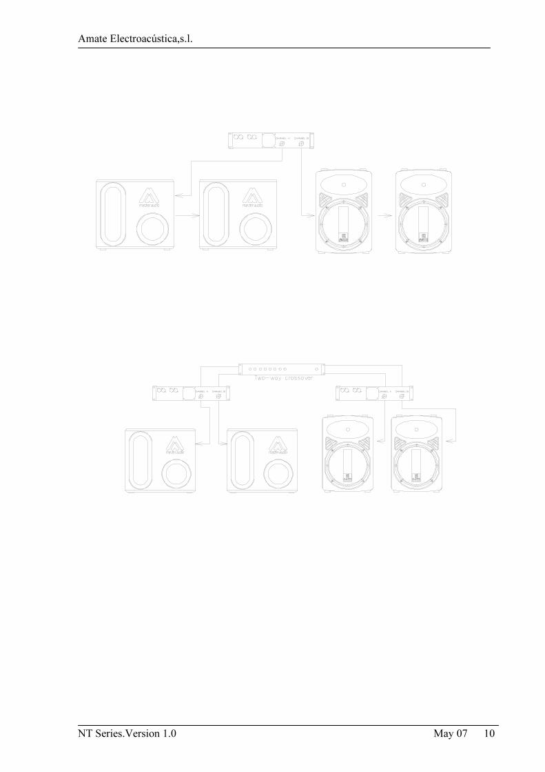
2.1.5.Configuración en Pasivo con Subwoofer (modelos Pasivos)
En este caso se dispondrá de un sólo
amplificador para todo el sistema.
De una de las salidas del amplificador
conectar, mediante cable manguera, la unidad
de graves.
Posteriormente, efectuar un puente desde el
conector Speakon esclavo del subwoofer a su
respectiva unidad satélite de medios-agudos,
respetando siempre la correcta polaridad entre
ambos sistemas. Proceder de igual manera para
el otro canal.
También es correcto, si la instalación lo
requiere, efectuar la conexión a la inversa, es
decir, del amplificador al satélite y luego al
subwoofer.
2.1.6.Configuración Bi-Amplificada con Subwoofer (Modelos pasivos)
Del canal de salida de la etapa de potencia
destinada a graves saldremos con una
manguera de la mayor sección posible (4mm2
mínimo) hacia uno de los subwoofers.
Si se dispone de pareja de subwoofers,
realizaremos una conexión en puente entre
ambos, respetando siempre la polaridad.
Conectar la otra salida del amplificador
independientemente a la caja de medios-
agudos.
También es posible destinar un sólo
amplificador para los refuerzos de graves,
conectando cada uno de los subwoofers a las
dos salidas de la etapa y en consecuencia,
alimentar el sistema de medios-agudos
mediante un segundo amplificador.
2.1.5. Passive configuration with Subwoofer (Passive models) In this case one amplifier will be only used for
the whole system.
Connect one of the outputs of the amplifier to
the subwoofer through a wire.
Then, make a bridge from the slave Speakon
connector of the subwoofer to its respective
mid-high satellite unit, always respecting the
correct polarity between both systems.
Do the same with the other channel.
It is also correct, if the installation requires so,
to make the connection in the opposite way,
that is, from the amplifier to the satellite and
then to the subwoofer.
2.1.6. Bi-Amplified configuration with Subwoofer (Passive models)
A wire with the maximum available section
(4mm2 minimum) will have to link the low
frequencies output channel of the amplifier to
one of the subwoofers.
Two subwoofers can be also connected by
bridge one to another, as long as the polarity is
strictly respected.
Connect the other output of the amplifier to the
Full Range cabinets.
It is also possible to use only one amplifier for
the low reinforcement, connecting each one of
the subwoofers to the two outputs of the
amplifier and consequently, connecting the
Full Range cabinets to a second amplifier.
Amate Electroacústica,s.l.
NT Series.Version 1.0 May 07 10
Amate Electroacústica,s.l.
NT Series.Version 1.0 May 07 11
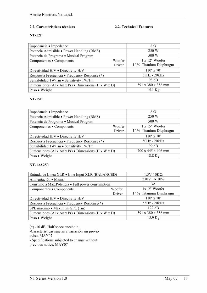
2.2. Características técnicas
NT-12P
NT-15P
NT-12A250
(*) -10 dB. Half space anechoic
-Características sujetas a variación sin previo aviso. MAY07
- Specifications subjected to change without previous notice. MAY07
2.2. Technical Features
Impedancia • Impedance 8 Ω
Potencia Admisible • Power Handling (RMS) 250 W
Potencia de Programa • Musical Program 500 W
Componentes • Components Woofer
Driver
1 x 12" Woofer
1" ½ Titanium Diaphragm
Directividad H/V • Directivity H/V 110º x 70º
Respuesta Frecuencia • Frequency Response (*) 55Hz - 20kHz
Sensibilidad 1W/1m • Sensitivity 1W/1m 98 dB
Dimensiones (Al x An x Pr) • Dimensions (H x W x D) 591 x 380 x 358 mm
Peso • Weight 15.1 Kg
Impedancia • Impedance 8 Ω
Potencia Admisible • Power Handling (RMS) 250 W
Potencia de Programa • Musical Program 500 W
Componentes • Components Woofer
Driver
1 x 15" Woofer
1" ½ Titanium Diaphragm
Directividad H/V • Directivity H/V 110º x 70º
Respuesta Frecuencia • Frequency Response (*) 50Hz - 20kHz
Sensibilidad 1W/1m • Sensitivity 1W/1m 99 dB
Dimensiones (Al x An x Pr) • Dimensions (H x W x D) 700 x 445 x 406 mm
Peso • Weight 18.8 Kg
Entrada de Línea XLR • Line Input XLR (BALANCED) 1.5V-10KΩ
Alimentación • Mains 230V +/- 10%
Consumo a Máx.Potencia • Full power consumption 3A
Componentes • Components Woofer
Driver
1x12" Woofer
1" ½ Titanium Diaphragm
Directividad H/V • Directivity H/V 110º x 70º
Respuesta Frecuencia • Frequency Response(*) 55Hz - 20kHz
SPL máximo • Maximum SPL (1m) 122 dB
Dimensiones (Al x An x Pr) • Dimensions (H x W x D) 591 x 380 x 358 mm
Peso • Weight 15.9 Kg
Amate Electroacústica,s.l.
NT Series.Version 1.0 May 07 12
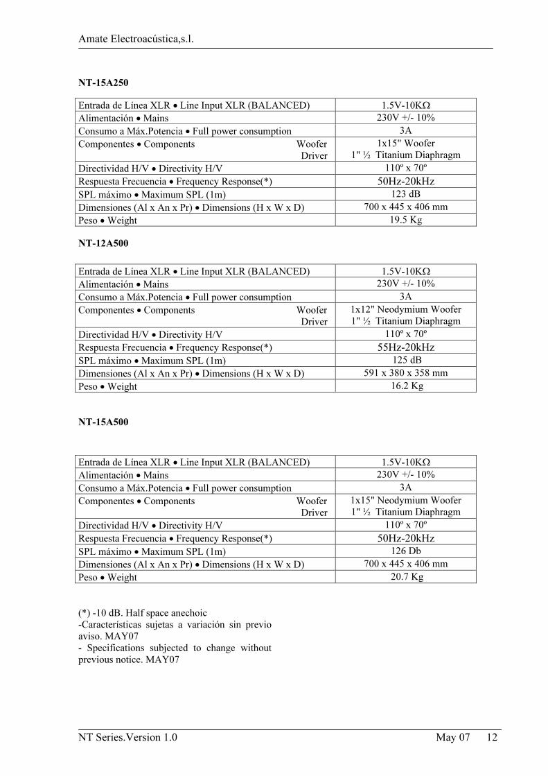
NT-15A250
NT-12A500
NT-15A500
(*) -10 dB. Half space anechoic
-Características sujetas a variación sin previo
aviso. MAY07
- Specifications subjected to change without
previous notice. MAY07
Entrada de Línea XLR • Line Input XLR (BALANCED) 1.5V-10KΩ
Alimentación • Mains 230V +/- 10%
Consumo a Máx.Potencia • Full power consumption 3A
Componentes • Components Woofer
Driver
1x15" Woofer
1" ½ Titanium Diaphragm
Directividad H/V • Directivity H/V 110º x 70º
Respuesta Frecuencia • Frequency Response(*) 50Hz-20kHz
SPL máximo • Maximum SPL (1m) 123 dB
Dimensiones (Al x An x Pr) • Dimensions (H x W x D) 700 x 445 x 406 mm
Peso • Weight 19.5 Kg
Entrada de Línea XLR • Line Input XLR (BALANCED) 1.5V-10KΩ
Alimentación • Mains 230V +/- 10%
Consumo a Máx.Potencia • Full power consumption 3A
Componentes • Components Woofer
Driver
1x12" Neodymium Woofer
1" ½ Titanium Diaphragm
Directividad H/V • Directivity H/V 110º x 70º
Respuesta Frecuencia • Frequency Response(*) 55Hz-20kHz
SPL máximo • Maximum SPL (1m) 125 dB
Dimensiones (Al x An x Pr) • Dimensions (H x W x D) 591 x 380 x 358 mm
Peso • Weight 16.2 Kg
Entrada de Línea XLR • Line Input XLR (BALANCED) 1.5V-10KΩ
Alimentación • Mains 230V +/- 10%
Consumo a Máx.Potencia • Full power consumption 3A
Componentes • Components Woofer
Driver
1x15" Neodymium Woofer
1" ½ Titanium Diaphragm
Directividad H/V • Directivity H/V 110º x 70º
Respuesta Frecuencia • Frequency Response(*) 50Hz-20kHz
SPL máximo • Maximum SPL (1m) 126 Db
Dimensiones (Al x An x Pr) • Dimensions (H x W x D) 700 x 445 x 406 mm
Peso • Weight 20.7 Kg
Amate Electroacústica,s.l.
NT Series.Version 1.0 May 07 13
3-MONTAJE E INSTALACIÓN Para la adecuada instalación de los sistemas de
cajas acústicas se recomienda lea atentamente
los siguientes consejos.
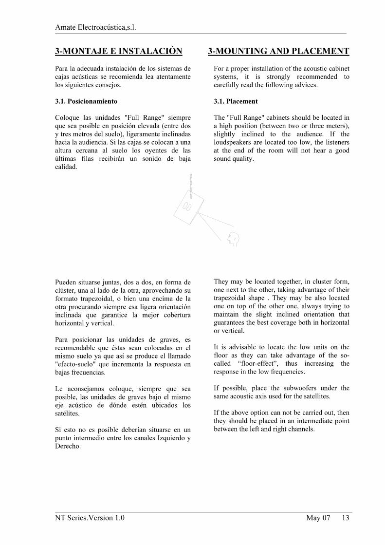
3.1. Posicionamiento Coloque las unidades "Full Range" siempre
que sea posible en posición elevada (entre dos
y tres metros del suelo), ligeramente inclinadas
hacia la audiencia. Si las cajas se colocan a una
altura cercana al suelo los oyentes de las
últimas filas recibirán un sonido de baja
calidad.
Pueden situarse juntas, dos a dos, en forma de
clúster, una al lado de la otra, aprovechando su
formato trapezoidal, o bien una encima de la
otra procurando siempre esa ligera orientación
inclinada que garantice la mejor cobertura
horizontal y vertical.
Para posicionar las unidades de graves, es
recomendable que éstas sean colocadas en el
mismo suelo ya que así se produce el llamado
"efecto-suelo" que incrementa la respuesta en
bajas frecuencias.
Le aconsejamos coloque, siempre que sea
posible, las unidades de graves bajo el mismo
eje acústico de dónde estén ubicados los
satélites.
Si esto no es posible deberían situarse en un
punto intermedio entre los canales Izquierdo y
Derecho.
3-MOUNTING AND PLACEMENT For a proper installation of the acoustic cabinet
systems, it is strongly recommended to
carefully read the following advices.
3.1. Placement The "Full Range" cabinets should be located in
a high position (between two or three meters),
slightly inclined to the audience. If the
loudspeakers are located too low, the listeners
at the end of the room will not hear a good
sound quality.
They may be located together, in cluster form,
one next to the other, taking advantage of their
trapezoidal shape . They may be also located
one on top of the other one, always trying to
maintain the slight inclined orientation that
guarantees the best coverage both in horizontal
or vertical.
It is advisable to locate the low units on the
floor as they can take advantage of the so-
called “floor-effect”, thus increasing the
response in the low frequencies.
If possible, place the subwoofers under the
same acoustic axis used for the satellites.
If the above option can not be carried out, then
they should be placed in an intermediate point
between the left and right channels.
Amate Electroacústica,s.l.
NT Series.Version 1.0 May 07 14
3.2. Uso con trípode Todos los modelos incorporan en su parte
inferior un vaso para trípode Standard de
35mm.
No utilice el trípode en superficies con
pendiente ni coloque las cajas demasiado altas,
pues el sistema puede ser totalmente inestable.
3.3. Uso como monitor La forma trapezoidal de todos los modelos
permite su utilización como monitor de
escenario sin la necesidad de incorporar ningún
accesorio extra.
3.4. Giro del logotipo Los logotipos de los modelos pueden girarse. 3.5. Volado Sólo personal especializado debe realizar el
volado de sistemas acústicos. Asegúrese del
peso que es capaz de soportar la estructura
sobre la cual se va a colgar la caja.
El hardware de volado (cadenas, pasadores,
anillas...) debe ser revisado regularmente y, en
caso de cualquier duda, debe ser reemplazado
por material nuevo.
¡ATENCIÓN!!! ¡NO COLGAR NUNCA LAS
CAJAS POR EL ASA!!!!
Todos los recintos disponen de 4 puntos de
suspensión M10, en el sobre, parte inferior y
partes laterales. Adicionalmente, el punto M8
donde se encuentra el pomo para fijar la caja al
trípode puede ser utilizado para dar la
inclinación necesaria. Su correcta combinación
permite el volado de las cajas tanto en posición
horizontal como en vertical.
3.2. Tripod use All the models are equipped with a tripod
socket for use with Standard 35mm tripods.
Do not use the tripod on non-flat floors and be
careful not to raise the cabinets too high on the
tripod, as they may become unstable.
3.3. Stage monitor use All models are trapezoidal-shaped and they can
be used as floor monitors without extra
accessories.
3.4. Rotatory Logo All model marks can be rotated. 3.5. Flying
Only experienced people should fly speaker
cabinets. Extreme care should be taken to
assure the load bearing capabilities of the
structures where the cabinets will be placed.
Hanging hardware (as chains, eyebolt, Lock
Pins...) should be regularly inspected and
replaced if in doubt.
WARNING!!! DO NOT SUSPEND THE
CABINETS FROM THE HANDLES!!!!
All models provide 4 M10 threaded flying
points on top, bottom and laterals.
Additionally, the M8 thread for fixing the
tripod can be used as an additional point to
angle the box down.
Amate Electroacústica,s.l.
NT Series.Version 1.0 May 07 15
1
3
2
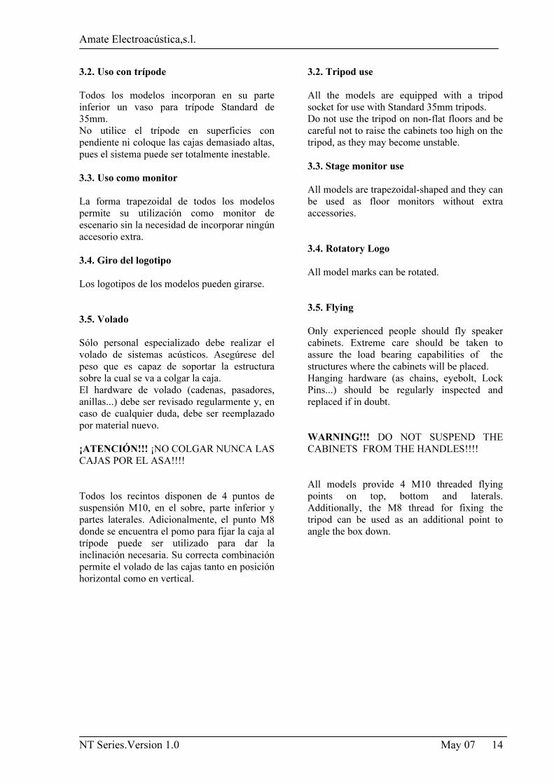
Volado horizontal
Puntos 1 y 2. Utilice el punto 3 o 4 para dar la
inclinación necesaria.
Volado vertical
Puntos 3 y 4. Utilice el punto 5 para dar la
inclinación necesaria.
Como accesorio opcional de volado se
suministran anillas Rigging de M10 (ACR M10) y M8 (ACRM8).
4
5
Horizontal Flying
Points 1 and 2. Use point 3 or 4 to get the
desired inclination.
Vertical Flying
Points 3 and 4. Use point 5 to get the desired
inclination.
We offer as optional accessory the forged
eyebolt rigging M10 (ACR M10) and M8
(ACR M8).
Amate Electroacústica,s.l.
NT Series.Version 1.0 May 07 16
4-APÉNDICE
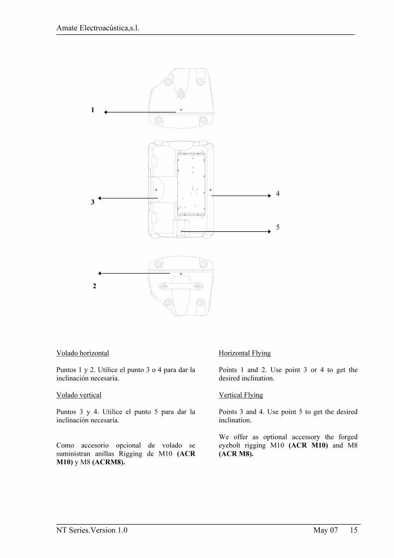
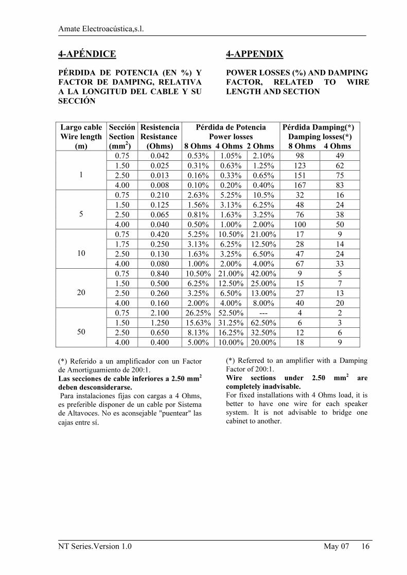
PÉRDIDA DE POTENCIA (EN %) Y FACTOR DE DAMPING, RELATIVA A LA LONGITUD DEL CABLE Y SU SECCIÓN
(*) Referido a un amplificador con un Factor
de Amortiguamiento de 200:1.
Las secciones de cable inferiores a 2.50 mm2 deben desconsiderarse. Para instalaciones fijas con cargas a 4 Ohms,
es preferible disponer de un cable por Sistema
de Altavoces. No es aconsejable "puentear" las
cajas entre sí.
4-APPENDIX POWER LOSSES (%) AND DAMPING FACTOR, RELATED TO WIRE LENGTH AND SECTION
(*) Referred to an amplifier with a Damping
Factor of 200:1.
Wire sections under 2.50 mm2 are completely inadvisable. For fixed installations with 4 Ohms load, it is
better to have one wire for each speaker
system. It is not advisable to bridge one
cabinet to another.
Largo cable Wire length
(m)
Sección Section (mm2)
Resistencia Resistance
(Ohms)
Pérdida de Potencia Power losses
8 Ohms 4 Ohms 2 Ohms
Pérdida Damping(*) Damping losses(*)
8 Ohms 4 Ohms 0.75 0.042 0.53% 1.05% 2.10% 98 49
1.50 0.025 0.31% 0.63% 1.25% 123 62
2.50 0.013 0.16% 0.33% 0.65% 151 75
1 4.00 0.008 0.10% 0.20% 0.40% 167 83
0.75 0.210 2.63% 5.25% 10.5% 32 16
1.50 0.125 1.56% 3.13% 6.25% 48 24
2.50 0.065 0.81% 1.63% 3.25% 76 38
5 4.00 0.040 0.50% 1.00% 2.00% 100 50
0.75 0.420 5.25% 10.50% 21.00% 17 9
1.75 0.250 3.13% 6.25% 12.50% 28 14
2.50 0.130 1.63% 3.25% 6.50% 47 24
10
4.00 0.080 1.00% 2.00% 4.00% 67 33
0.75 0.840 10.50% 21.00% 42.00% 9 5
1.50 0.500 6.25% 12.50% 25.00% 15 7
2.50 0.260 3.25% 6.50% 13.00% 27 13
20
4.00 0.160 2.00% 4.00% 8.00% 40 20
0.75 2.100 26.25% 52.50% --- 4 2
1.50 1.250 15.63% 31.25% 62.50% 6 3
2.50 0.650 8.13% 16.25% 32.50% 12 6
50
4.00 0.400 5.00% 10.00% 20.00% 18 9
Amate Electroacústica,s.l.
NT Series.Version 1.0 May 07 17
5.SOLUCIÓN DE PROBLEMAS Sin alimentación
• Asegúrese que el aparato esté conectado a la
red.
• El Fusible puede estar fundido. Reemplace el
fusible situado en el portafusibles por otro del
mismo tipo. Si se vuelve a fundir, lleve su unidad
a un centro autorizado de reparación.
Sin sonido
• Compruebe en el indicador de salida del
mezclador que la señal está siendo enviada.
• Asegúrese que el potenciómetro de VOLUME
está correctamente posicionado.
• Compruebe que los cables de señal estén en
buenas condiciones y conectados en ambos
extremos.
• El nivel de salida del mezclador no debe estar
al mínimo.
• Revise que el mezclador no esté en Mute.
Señal de salida distorsionada y LEDS de
clipping activados
• El sistema está siendo sobrecargado con
demasiada señal de entrada y ha alcanzado la
máxima potencia. Bajar el nivel de salida del
mezclador o la ganancia de los canales.
Nivel de graves pobre
• Compruebe la polaridad de las conexiones entre
el mezclador y los altavoces. Si las conexiones
positivas y negativas están invertidas en un
extremo del cable, puede que un altavoz esté
fuera de fase.
Ruidos y zumbidos
• Asegúrese que todas las conexiones a las cajas
auto-amplificadas están en buenas condiciones.
• Evite que los cables de señal estén liados con
los cables de red o cerca de transformadores o
aparatos que emitan EMI.
• Compruebe que no hay ningún regulador de
intensidad de luz en el mismo circuito AC que la
caja. Conecte el circuito de sonido y el de luces
a distintas fases.
5.TROUBLESHOOTING No power
• Make sure that the cabinet is plug in.
• The Fuse is blown. Replace the fuse on fuse
holder with one of the same type. If it blows again,
take the unit to a service centre.
No sound
• Check that the mixer or sound source is sending
signal to the unit.
• Make sure that the VOLUME potentiometer is
well-positioned.
• Check that the cable from the sound source to the
units is connected correctly. Replace the cable if
defective.
• Make sure the output volume (gain) control on the
mixing console is turned up sufficiently to drive the
inputs of the speakers.
• Make sure the mixer does not have a Mute on.
Distorted sound and Clip Limiter LEDS Active
• The system is overloaded and has reached
maximum power. Turn down the mixer's output or
the channel's gain.
Poor bass performance
• Check the polarity of the connections between the
mixer and the cabinets. You may have the positive
and negative connections reversed at one end of the
cable, causing a loudspeaker to be out-of-phase.
Noise and Hum
• Make sure all connections to the active unit are in
good conditions.
• Avoid the signal cables to be routed near AC
cables, power transformers, or EMI-inducing
devices.
• Check if there is any light dimmer on the same
AC circuit as the cabinet. Connect the sound system
to a different phase than the lights
Amate Electroacústica , s.l
Pol.Ind.Norte. Perpinyà, 25
08226 TERRASSA (Barcelona-Spain)
Tel:+34-937356565 FAX:+34-937356048
Email: [email protected] www.master-audio.com