multisección 1/2013 - heidenhain · t1 = etiqueta de tipo t1 = id label a) cable de conexión b)...
TRANSCRIPT
Instrucciones de montaje Mounting Instructions
LB 302
LB 382 multisección Multi-Section
1/2013
2
Página 4 Componentes 6 Elementos suministrados 8 Indicaciones para el montaje Montaje 10 Configuración salida del cable 11 Posición de la marca de referencia LB 302/LB 382 12 Dimensiones 14 Tolerancias de montaje 16 Sujeción de las secciones de la carcasa 19 Inserción de los flejes de rodadura 20 Indicaciones para el montaje de la cinta de medida 21 Inserción y sujeción de la cinta de medida 24 Inserción de los labios 28 Sujeción de los labios (carcasa final E2) 29 Instalación del cabezal 30 Sujeción de los labios (carcasa final E1) 31 Trabajos finales del montaje 32 Tensar la cinta de medida 34 Compensación de errores lineales 36 Medidas de protección Datos mecánicos 37 LB 302/LB 302C 37 LB 382/LB 382C Conexión eléctrica 38 LB 302/LB 302C 40 LB 382/LB 382C Datos eléctricos 39 LB 302/LB 302C 41 LB 382/LB 382C
Page 4 Components 6 Items Supplied 8 Mounting Procedure Mounting 10 Changing the Cable Outlet 11 Reference Mark Position LB 302/LB 382 12 Dimensions 14 Mounting Tolerances 16 Mounting the Housing Sections 19 Inserting the Bearing Strips 20 Mounting the Scale Tape 21 Inserting and securing the Scale Tape 24 Inserting the Sealing Lips 28 Securing the Sealing Lips (End Section E2) 29 Installing the Scanning Unit 30 Securing the Sealing Lips (End Section E1) 31 Final Steps 32 Tensioning the Scale Tape 34 Linear Error Compensation 36 Protective Measures Mechanical Data 37 LB 302/LB 302C 37 LB 382/LB 382C Electrical Connection 38 LB 302/LB 302C 40 LB 382/LB 382C Electrical Data 39 LB 302/LB 302C 41 LB 382/LB 382C
Indice Contents
3
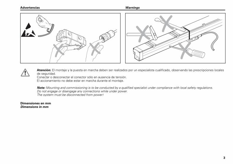
Atención: El montaje y la puesta en marcha deben ser realizados por un especialista cualificado, observando las prescripciones locales de seguridad. Conectar o desconectar el conector sólo en ausencia de tensión. El accionamiento no debe estar en marcha durante el montaje.
Note: Mounting and commissioning is to be conducted by a qualified specialist under compliance with local safety regulations. Do not engage or disengage any connections while under power. The system must be disconnected from power!
Dimensiones en mm Dimensions in mm
Advertencias Warnings
4
�
�
�
�
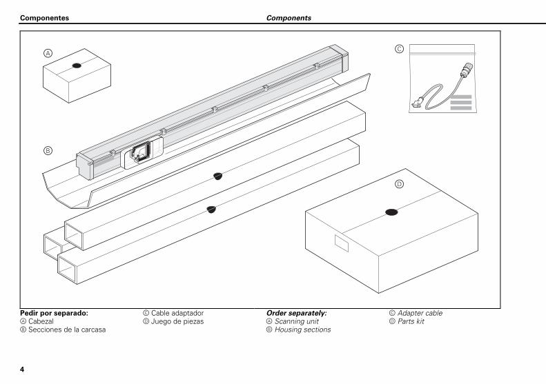
Pedir por separado: Cabezal Secciones de la carcasa
Cable adaptador Juego de piezas
Order separately: Scanning unit Housing sections
Adapter cable Parts kit
Componentes Components
5
�
��
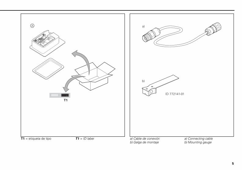
T1 = etiqueta de tipo T1 = ID label a) Cable de conexión b) Galga de montaje
a) Connecting cable b) Mounting gauge
6
�
����
�
�
������
�
��
������� ���� � ������� ��� ���������������� ����
������ ��
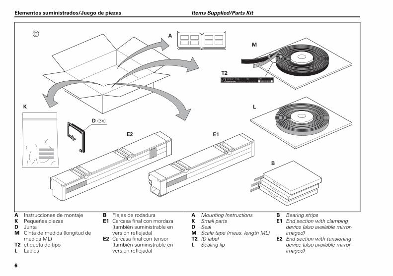
A Instrucciones de montaje K Pequeñas piezas D Junta M Cinta de medida (longitud de
medida ML) T2 etiqueta de tipo L Labios
B Flejes de rodadura E1 Carcasa final con mordaza
(también suministrable en versión reflejada)
E2 Carcasa final con tensor (también suministrable en versión reflejada)
A Mounting Instructions K Small parts D Seal M Scale tape (meas. length ML) T2 ID label L Sealing lip
B Bearing strips E1 End section with clamping
device (also available mirror-imaged)
E2 End section with tensioning device (also available mirror-imaged)
Elementos suministrados/Juego de piezas Items Supplied/Parts Kit
7
�����
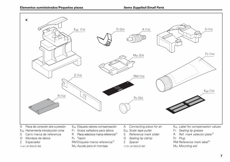
A Pieza de conexión aire a presión EW Herramienta introducción cinta S Carro marca de referencia O Mordaza de labios Z Espaciador 1) en LB 302/LB 382
KW Etiqueta valores compensación FT Grasa selladora para labios R Placa selectora marca referencia1) PF Tapón RM Etiqueta marca referencia1) MH Ayuda para el montaje
A Connecting piece for air EW Scale tape puller S Reference mark slider O Sealing lip clamp Z Spacer 1) for LB 302/LB 382
KW Label for compensation values FT Sealing lip grease R Ref. mark selector plate1) PF Plug RM Reference mark label1) MH Mounting aid
Elementos suministrados/Pequeñas piezas Items Supplied/Small Parts
8
��!
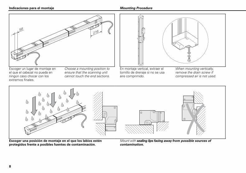
Escoger un lugar de montaje en el que el cabezal no pueda en ningún caso chocar con los extremos finales.
Choose a mounting position to ensure that the scanning unit cannot touch the end sections.
En montaje vertical, extraer el tornillo de drenaje si no se usa aire comprimido.
When mounting vertically, remove the drain screw if compressed air is not used.
Escoger una posición de montaje en el que los labios estén protegidos frente a posibles fuentes de contaminación.
Mount with sealing lips facing away from possible sources of contamination.
Indicaciones para el montaje Mounting Procedure

9
Durante el montaje debe prestarse atención a que no entre suciedad en el interior de la carcasa de la regla.
Be sure that no contamination enters the housing while you are mounting the scale.
No tocar el lado graduado de la cinta de medida. No doblar la cinta de medida.
Do not touch the graduation side of the scale tape. Do not bend the scale tape.
10
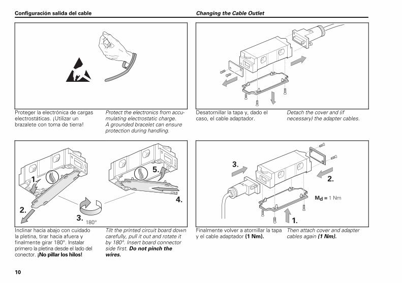
Proteger la electrónica de cargas electrostáticas. ¡Utilizar un brazalete con toma de tierra!
Protect the electronics from accu-mulating electrostatic charge. A grounded bracelet can ensure protection during handling.
Desatornillar la tapa y, dado el caso, el cable adaptador.
Detach the cover and (if necessary) the adapter cables.
��
��
���"
��
��
��
��
�������
��
Inclinar hacia abajo con cuidado la pletina, tirar hacia afuera y finalmente girar 180°. Instalar primero la pletina desde el lado del conector. ¡No pillar los hilos!
Tilt the printed circuit board down carefully, pull it out and rotate it by 180°. Insert board connector side first. Do not pinch the wires.
Finalmente volver a atornillar la tapa y el cable adaptador (1 Nm).
Then attach cover and adapter cables again (1 Nm).
Configuración salida del cable Changing the Cable Outlet
11
����
����
����
����
����
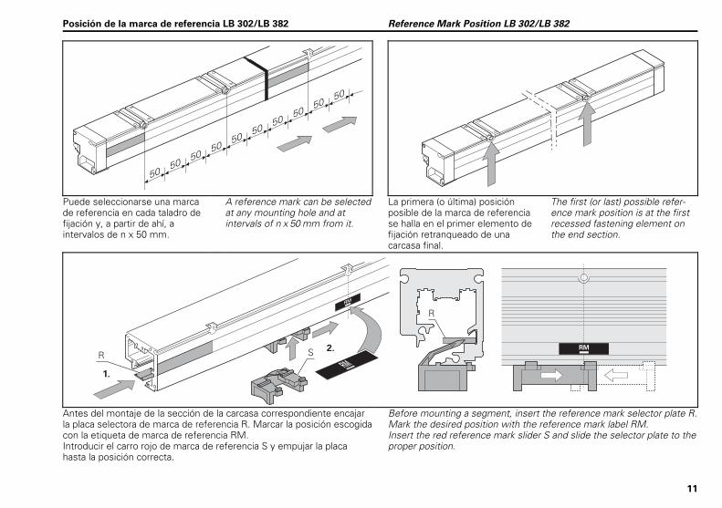
Puede seleccionarse una marca de referencia en cada taladro de fijación y, a partir de ahí, a intervalos de n x 50 mm.
A reference mark can be selected at any mounting hole and at intervals of n x 50 mm from it.
La primera (o última) posición posible de la marca de referencia se halla en el primer elemento de fijación retranqueado de una carcasa final.
The first (or last) possible refer-ence mark position is at the first recessed fastening element on the end section.
��
�
��
�
��
���
��
Antes del montaje de la sección de la carcasa correspondiente encajar la placa selectora de marca de referencia R. Marcar la posición escogida con la etiqueta de marca de referencia RM. Introducir el carro rojo de marca de referencia S y empujar la placa hasta la posición correcta.
Before mounting a segment, insert the reference mark selector plate R. Mark the desired position with the reference mark label RM. Insert the red reference mark slider S and slide the selector plate to the proper position.
Posición de la marca de referencia LB 302/LB 382 Reference Mark Position LB 302/LB 382
12
�
�
���
�� ���
������ ��
��
� ��
�
�
����
������������� �
����� �
�� ��
��
������ �
����
� �
�
�
�����
����
�
�����
�
�
����� ��
�
���������� �������������������
���
������ ��
��
�������� �
�
��� ��� �
�
�
��
���
��� ���
�����
�
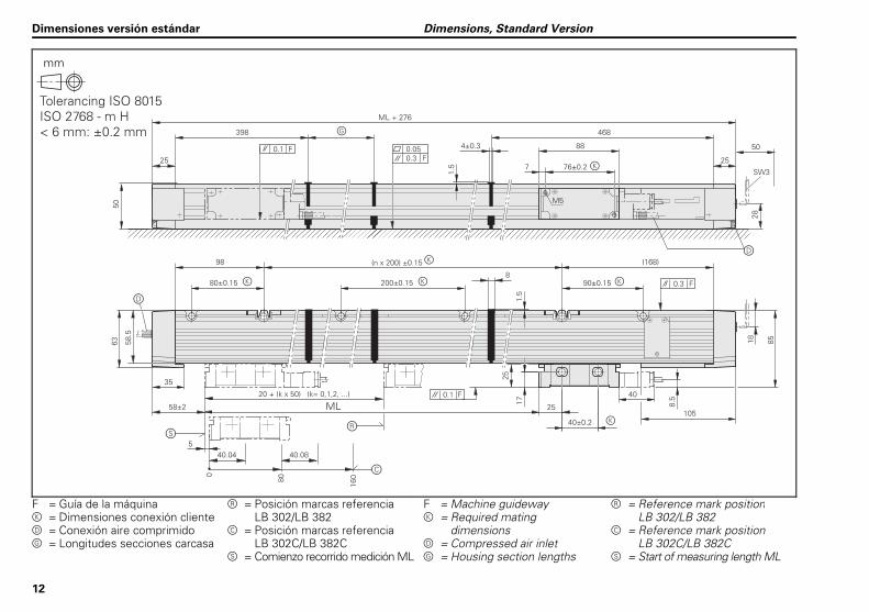
F = Guía de la máquina = Dimensiones conexión cliente = Conexión aire comprimido = Longitudes secciones carcasa
= Posición marcas referencia LB 302/LB 382 = Posición marcas referencia LB 302C/LB 382C = Comienzo recorrido medición ML
F = Machine guideway = Required mating dimensions = Compressed air inlet = Housing section lengths
= Reference mark position LB 302/LB 382 = Reference mark position LB 302C/LB 382C = Start of measuring length ML
Dimensiones versión estándar Dimensions, Standard Version
mm
�#$� ��%��&���'�� ��'��(!������)*�!���+�,-����
13
�
�
����
��
���
��
������ ��
��
� ��
�
�
��
�
�
�����
��
��
�
�����
������������� �
����� �
����
������ �
��
�
�
�
�
���� ����� ��
�
���������� �������������������
��������
�
�
��
�
���
��� ��� ���
���
������ ��
�
�����
�
��
�
���
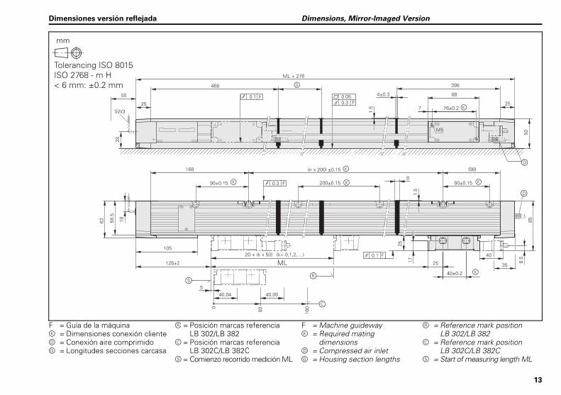
F = Guía de la máquina = Dimensiones conexión cliente = Conexión aire comprimido = Longitudes secciones carcasa
= Posición marcas referencia LB 302/LB 382 = Posición marcas referencia LB 302C/LB 382C = Comienzo recorrido medición ML
F = Machine guideway = Required mating dimensions = Compressed air inlet = Housing section lengths
= Reference mark position LB 302/LB 382 = Reference mark position LB 302C/LB 382C = Start of measuring length ML
Dimensiones versión reflejada Dimensions, Mirror-Imaged Version
mm
�#$� ��%��&���'�� ��'��(!������)*�!���+�,-����
14
������
��������
����
�
� ���
����
��������
������ ����
���������������������� ��
�������
������
�������
�
�
�
��
�
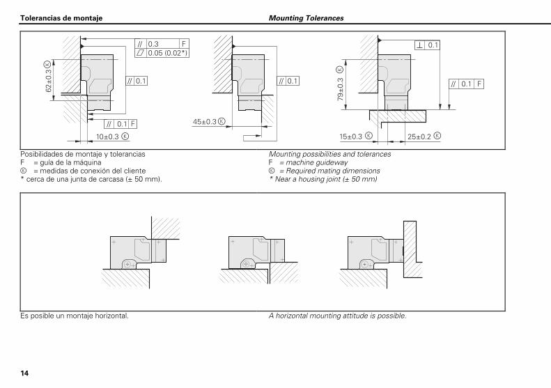
Posibilidades de montaje y tolerancias F = guía de la máquina = medidas de conexión del cliente * cerca de una junta de carcasa (± 50 mm).
Mounting possibilities and tolerances F = machine guideway = Required mating dimensions * Near a housing joint (± 50 mm)
Es posible un montaje horizontal. A horizontal mounting attitude is possible.
Tolerancias de montaje Mounting Tolerances
15
��
���������������������� �
���������������������� �
��
�������������������� �
����������������������
�
����������
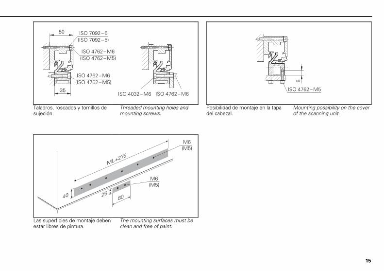
Taladros, roscados y tornillos de sujeción.
Threaded mounting holes and mounting screws.
Posibilidad de montaje en la tapa del cabezal.
Mounting possibility on the cover of the scanning unit.
�� ����
����
�� ���
�� ���
Las superficies de montaje deben estar libres de pintura.
The mounting surfaces must be clean and free of paint.
16
��
�!�� �
!
/..���
-����/
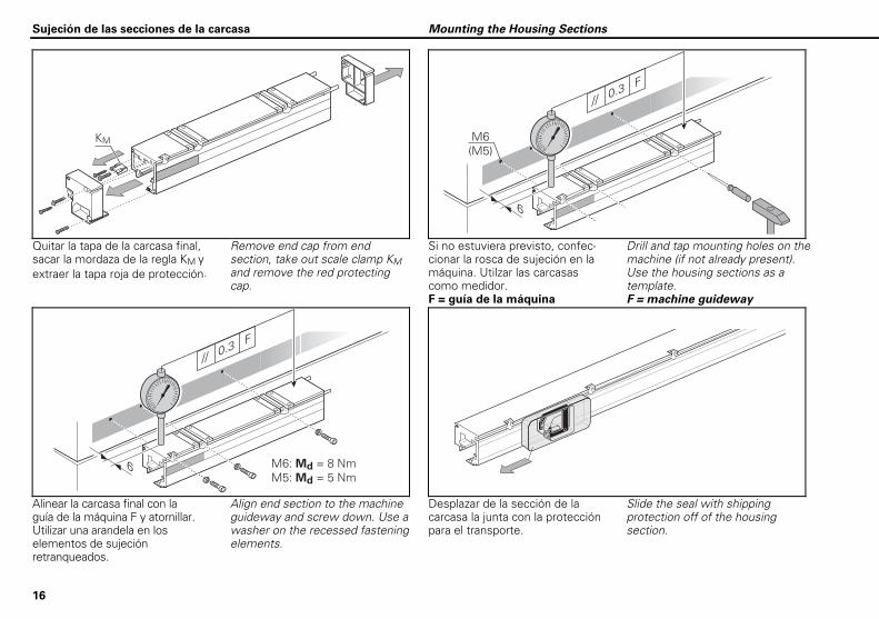
Quitar la tapa de la carcasa final, sacar la mordaza de la regla KM y extraer la tapa roja de protección.
Remove end cap from end section, take out scale clamp KM and remove the red protecting cap.
Si no estuviera previsto, confec-cionar la rosca de sujeción en la máquina. Utilzar las carcasas como medidor. F = guía de la máquina
Drill and tap mounting holes on the machine (if not already present). Use the housing sections as a template. F = machine guideway
!
/..���
-����/
�!+���4������ +���4� ���
Alinear la carcasa final con la guía de la máquina F y atornillar. Utilizar una arandela en los elementos de sujeción retranqueados.
Align end section to the machine guideway and screw down. Use a washer on the recessed fastening elements.
Desplazar de la sección de la carcasa la junta con la protección para el transporte.
Slide the seal with shipping protection off of the housing section.
Sujeción de las secciones de la carcasa Mounting the Housing Sections
17
� �
�������
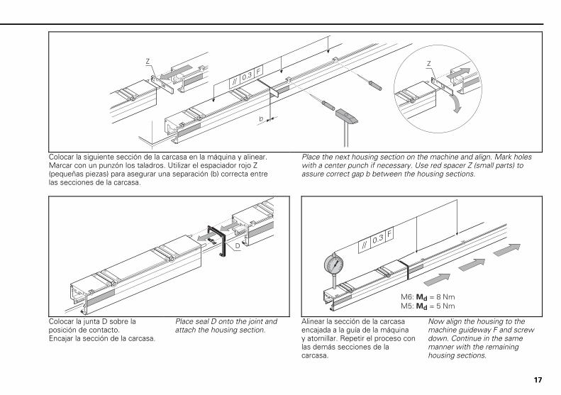
Colocar la siguiente sección de la carcasa en la máquina y alinear. Marcar con un punzón los taladros. Utilizar el espaciador rojo Z (pequeñas piezas) para asegurar una separación (b) correcta entre las secciones de la carcasa.
Place the next housing section on the machine and align. Mark holes with a center punch if necessary. Use red spacer Z (small parts) to assure correct gap b between the housing sections.
�
..���-�
/
�!+���4������ +���4� ���
Colocar la junta D sobre la posición de contacto. Encajar la sección de la carcasa.
Place seal D onto the joint and attach the housing section.
Alinear la sección de la carcasa encajada a la guía de la máquina y atornillar. Repetir el proceso con las demás secciones de la carcasa.
Now align the housing to the machine guideway F and screw down. Continue in the same manner with the remaining housing sections.
18
���
5�
�!+���4������ +���4� ���
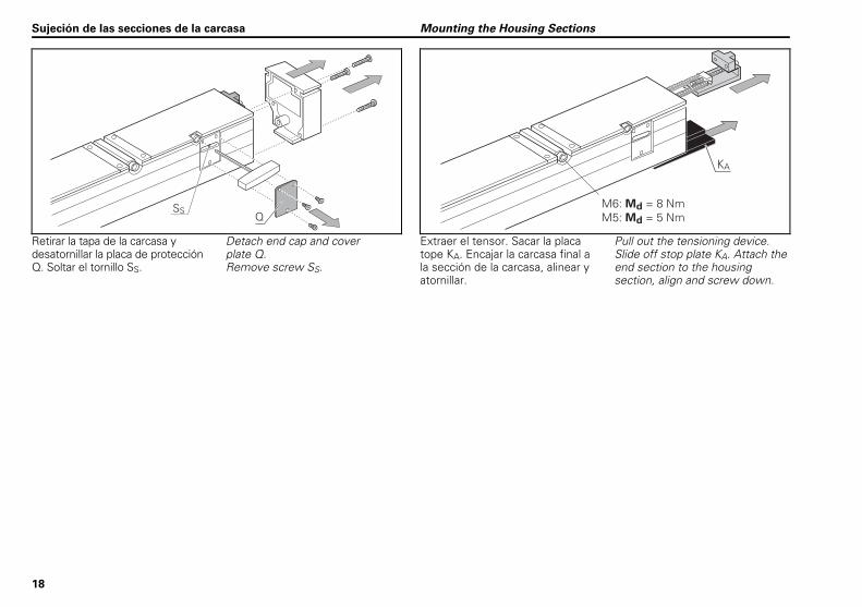
Retirar la tapa de la carcasa y desatornillar la placa de protección Q. Soltar el tornillo SS.
Detach end cap and cover plate Q. Remove screw SS.
Extraer el tensor. Sacar la placa tope KA. Encajar la carcasa final a la sección de la carcasa, alinear y atornillar.
Pull out the tensioning device. Slide off stop plate KA. Attach the end section to the housing section, align and screw down.
Sujeción de las secciones de la carcasa Mounting the Housing Sections
19
��
� �
�
�
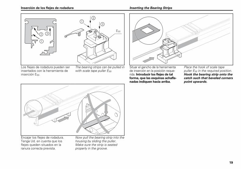
Los flejes de rodadura pueden ser insertados con la herramienta de inserción EW.
The bearing strips can be pulled inwith scale tape puller EW.
Situar el gancho de la herramienta de inserción en la posición reque-rida. Introducir los flejes de tal forma, que las esquinas achafla-nadas indiquen hacia arriba.
Place the hook of scale tape puller EW in the required position. Hook the bearing strip onto the catch such that beveled corners point upwards.
Encajar los flejes de rodadura. Tenga Ud. en cuenta que los flejes queden situados en la ranura correcta prevista.
Now pull the bearing strip into the housing by sliding the puller. Make sure the strip is seated properly in the groove.
Inserción de los flejes de rodadura Inserting the Bearing Strips
20
�� �
�����
��
���
�����������
��
��
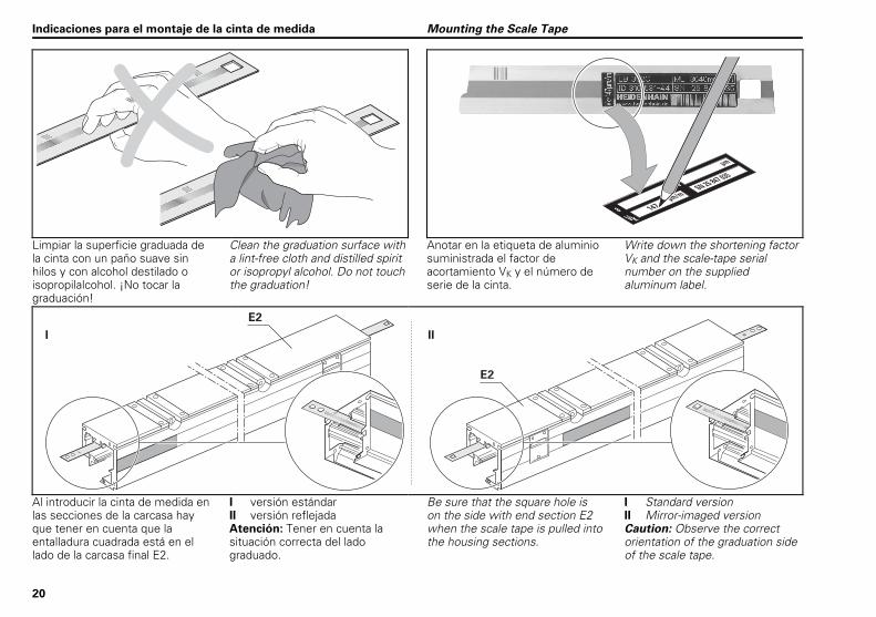
Limpiar la superficie graduada de la cinta con un paño suave sin hilos y con alcohol destilado o isopropilalcohol. ¡No tocar la graduación!
Clean the graduation surface with a lint-free cloth and distilled spirit or isopropyl alcohol. Do not touch the graduation!
Anotar en la etiqueta de aluminio suministrada el factor de acortamiento VK y el número de serie de la cinta.
Write down the shortening factor VK and the scale-tape serial number on the supplied aluminum label.
�
�� ��
��
Al introducir la cinta de medida en las secciones de la carcasa hay que tener en cuenta que la entalladura cuadrada está en el lado de la carcasa final E2.
I versión estándar II versión reflejada Atención: Tener en cuenta la situación correcta del lado graduado.
Be sure that the square hole is on the side with end section E2 when the scale tape is pulled into the housing sections.
I Standard version II Mirror-imaged version Caution: Observe the correct orientation of the graduation side of the scale tape.
Indicaciones para el montaje de la cinta de medida Mounting the Scale Tape
21
��
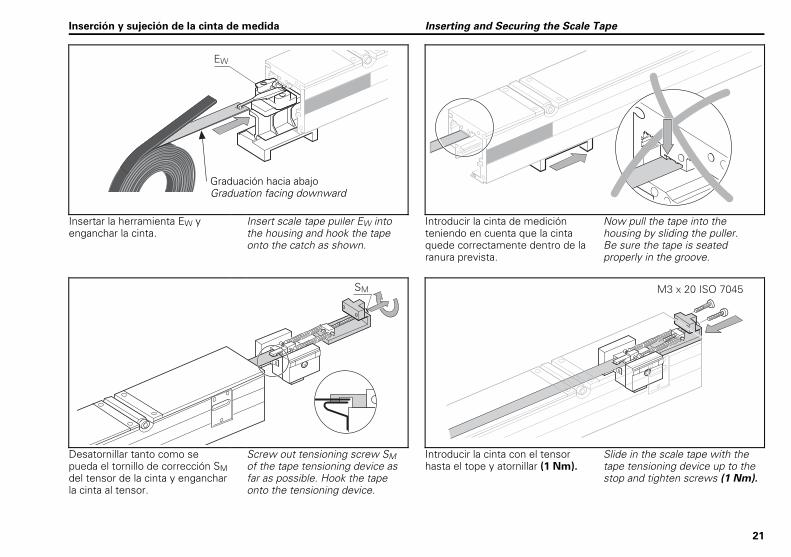
Insertar la herramienta EW y enganchar la cinta.
Insert scale tape puller EW into the housing and hook the tape onto the catch as shown.
Introducir la cinta de medición teniendo en cuenta que la cinta quede correctamente dentro de la ranura prevista.
Now pull the tape into the housing by sliding the puller. Be sure the tape is seated properly in the groove.
�� ����������������
Desatornillar tanto como se pueda el tornillo de corrección SM del tensor de la cinta y enganchar la cinta al tensor.
Screw out tensioning screw SM of the tape tensioning device as far as possible. Hook the tape onto the tensioning device.
Introducir la cinta con el tensor hasta el tope y atornillar (1 Nm).
Slide in the scale tape with the tape tensioning device up to the stop and tighten screws (1 Nm).
Inserción y sujeción de la cinta de medida Inserting and Securing the Scale Tape
Graduación hacia abajo Graduation facing downward
22
��
��
���������������
�� ��
��
��
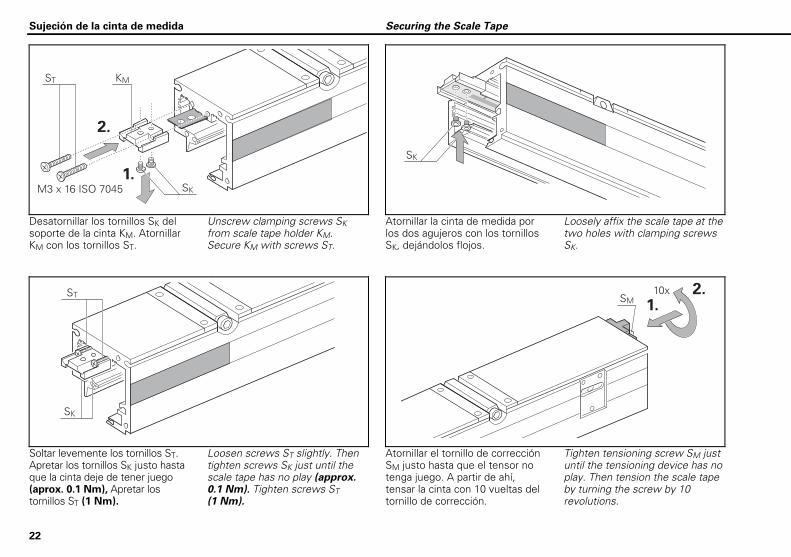
Desatornillar los tornillos SK del soporte de la cinta KM. Atornillar KM con los tornillos ST.
Unscrew clamping screws SK from scale tape holder KM. Secure KM with screws ST.
Atornillar la cinta de medida por los dos agujeros con los tornillos SK, dejándolos flojos.
Loosely affix the scale tape at the two holes with clamping screws SK.
��
��
���
����
��
Soltar levemente los tornillos ST. Apretar los tornillos SK justo hasta que la cinta deje de tener juego (aprox. 0.1 Nm), Apretar los tornillos ST (1 Nm).
Loosen screws ST slightly. Then tighten screws SK just until the scale tape has no play (approx. 0.1 Nm). Tighten screws ST (1 Nm).
Atornillar el tornillo de corrección SM justo hasta que el tensor no tenga juego. A partir de ahí, tensar la cinta con 10 vueltas del tornillo de corrección.
Tighten tensioning screw SM just until the tensioning device has no play. Then tension the scale tape by turning the screw by 10 revolutions.
Sujeción de la cinta de medida Securing the Scale Tape
23
��4���������-
�5
�����
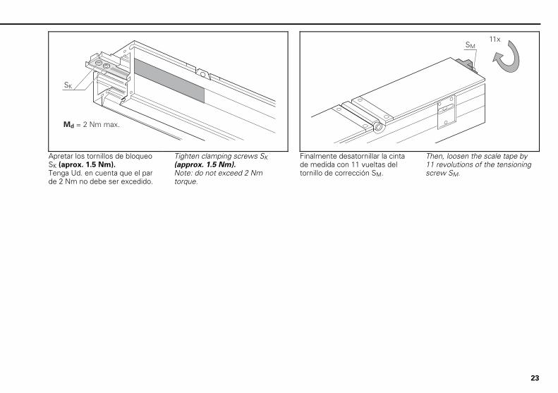
Apretar los tornillos de bloqueo SK (aprox. 1.5 Nm). Tenga Ud. en cuenta que el par de 2 Nm no debe ser excedido.
Tighten clamping screws SK (approx. 1.5 Nm). Note: do not exceed 2 Nm torque.
Finalmente desatornillar la cinta de medida con 11 vueltas del tornillo de corrección SM.
Then, loosen the scale tape by 11 revolutions of the tensioning screw SM.
24
��4�����3���!����-00
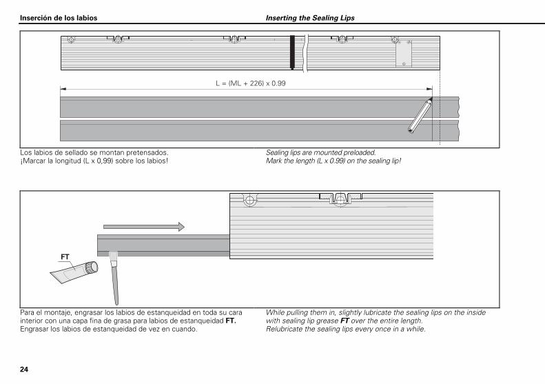
Los labios de sellado se montan pretensados. ¡Marcar la longitud (L x 0,99) sobre los labios!
Sealing lips are mounted preloaded. Mark the length (L x 0.99) on the sealing lip!
�
Para el montaje, engrasar los labios de estanqueidad en toda su cara interior con una capa fina de grasa para labios de estanqueidad FT. Engrasar los labios de estanqueidad de vez en cuando.
While pulling them in, slightly lubricate the sealing lips on the inside with sealing lip grease FT over the entire length. Relubricate the sealing lips every once in a while.
Inserción de los labios Inserting the Sealing Lips
25
!"
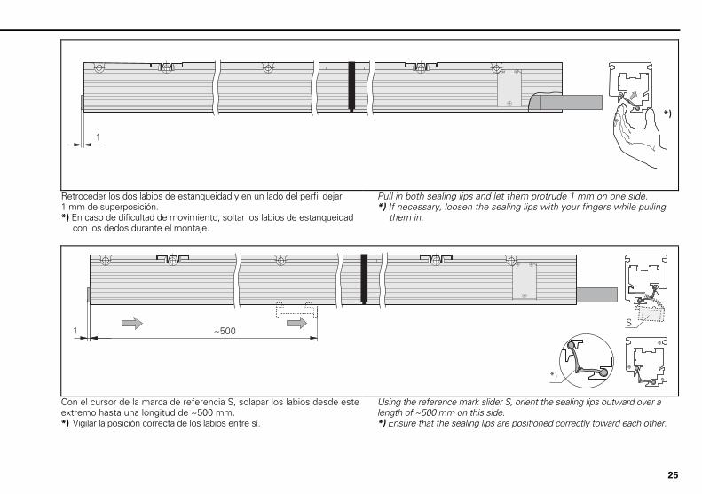
Retroceder los dos labios de estanqueidad y en un lado del perfil dejar 1 mm de superposición. *) En caso de dificultad de movimiento, soltar los labios de estanqueidad
con los dedos durante el montaje.
Pull in both sealing lips and let them protrude 1 mm on one side. *) If necessary, loosen the sealing lips with your fingers while pulling
them in.
6 �
1�
Con el cursor de la marca de referencia S, solapar los labios desde este extremo hasta una longitud de ~500 mm. *) Vigilar la posición correcta de los labios entre sí.
Using the reference mark slider S, orient the sealing lips outward over a length of ~500 mm on this side. *) Ensure that the sealing lips are positioned correctly toward each other.
26
6
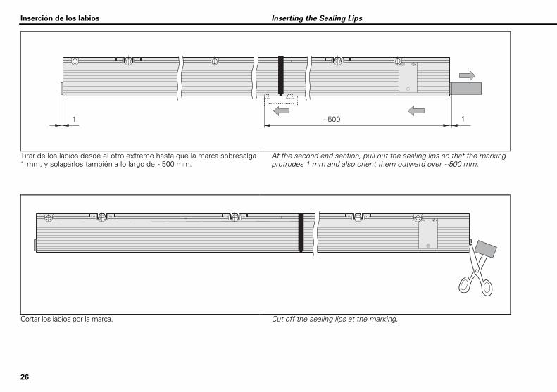
Tirar de los labios desde el otro extremo hasta que la marca sobresalga 1 mm, y solaparlos también a lo largo de ~500 mm.
At the second end section, pull out the sealing lips so that the marking protrudes 1 mm and also orient them outward over ~500 mm.
Cortar los labios por la marca. Cut off the sealing lips at the marking.
Inserción de los labios Inserting the Sealing Lips
27
�
7
�
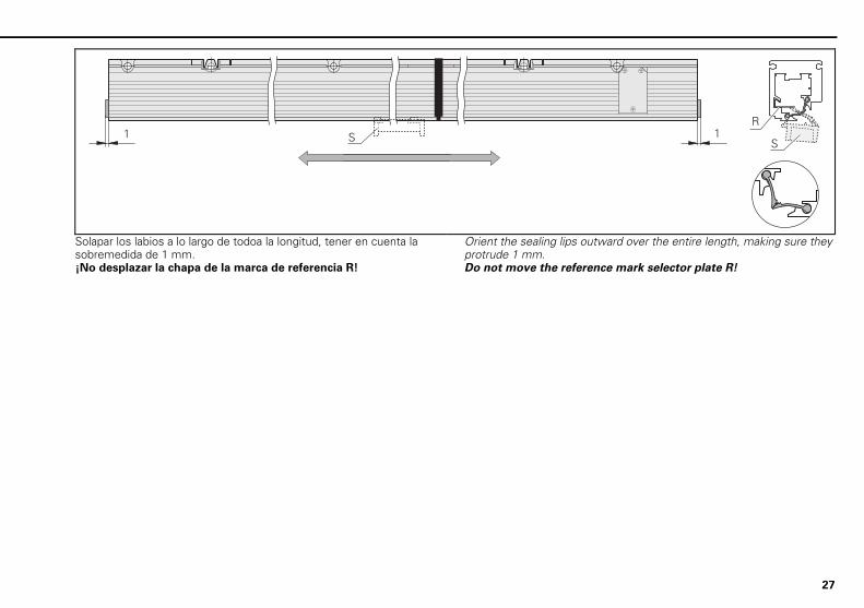
Solapar los labios a lo largo de todoa la longitud, tener en cuenta la sobremedida de 1 mm. ¡No desplazar la chapa de la marca de referencia R!
Orient the sealing lips outward over the entire length, making sure they protrude 1 mm. Do not move the reference mark selector plate R!
28
��
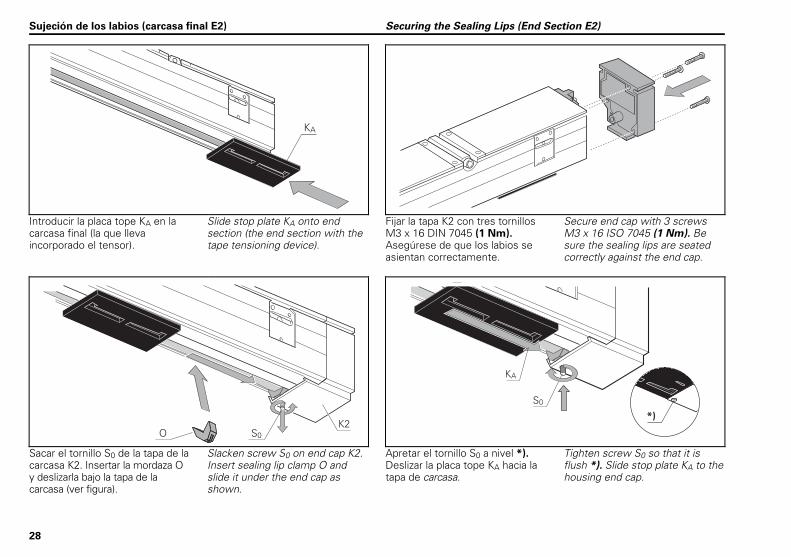
Introducir la placa tope KA en la carcasa final (la que lleva incorporado el tensor).
Slide stop plate KA onto end section (the end section with the tape tensioning device).
Fijar la tapa K2 con tres tornillos M3 x 16 DIN 7045 (1 Nm). Asegúrese de que los labios se asientan correctamente.
Secure end cap with 3 screws M3 x 16 ISO 7045 (1 Nm). Be sure the sealing lips are seated correctly against the end cap.
���
��
�
5�
!"
Sacar el tornillo S0 de la tapa de la carcasa K2. Insertar la mordaza O y deslizarla bajo la tapa de la carcasa (ver figura).
Slacken screw S0 on end cap K2. Insert sealing lip clamp O and slide it under the end cap as shown.
Apretar el tornillo S0 a nivel *). Deslizar la placa tope KA hacia la tapa de carcasa.
Tighten screw S0 so that it is flush *). Slide stop plate KA to the housing end cap.
Sujeción de los labios (carcasa final E2) Securing the Sealing Lips (End Section E2)
29
���((��2�
,-�
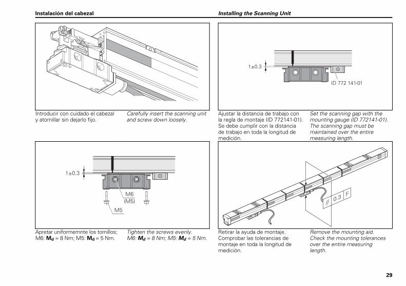
Introducir con cuidado el cabezal y atornillar sin dejarlo fijo.
Carefully insert the scanning unit and screw down loosely.
Ajustar la distancia de trabajo con la regla de montaje (ID 772141-01). Se debe cumplir con la distancia de trabajo en toda la longitud de medición.
Set the scanning gap with the mounting gauge (ID 772141-01). The scanning gap must be maintained over the entire measuring length.
,-�
�
�!�� �
..���-�
/
Apretar uniformemnte los tornillos; M6: Md = 8 Nm; M5: Md = 5 Nm.
Tighten the screws evenly. M6: Md = 8 Nm; M5: Md = 5 Nm.
Retirar la ayuda de montaje. Comprobar las tolerancias de montaje en toda la longitud de medición.
Remove the mounting aid. Check the mounting tolerances over the entire measuring length.
Instalación del cabezal Installing the Scanning Unit

30
��
� '!"
Atornillar la tapa de la carcasa y soltar los tornillos S0.
Screw on the end cap and loosen clamping screw S0.
Insertar la aprisionadora de labios de estanqueidad O y deslizarla debajo de la tapa de carcasa. Apretar el tornillo S0 a nivel *).
Insert sealing-lips clamp O and slide it under the housing end cap. Tighten screw S0 so that it is flush *).
Sujeción de los labios (carcasa final E1) Securing the Sealing Lips (End Section E1)
31
�
�
�
8��-
��-
��-
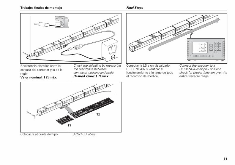
Resistencia eléctrica entre la carcasa del conector y la de la regla: Valor nominal: 1 máx.
Check the shielding by measuring the resistance between connector housing and scale. Desired value: 1 max.
Conectar la LB a un visualizador HEIDENHAIN y verificar el funcionamiento a lo largo de todo el recorrido de medida.
Connect the encoder to a HEIDENHAIN display unit and check for proper function over the entire traverse range.
��
������#
�
###�###$
##
��
##
Colocar la etiqueta del tipo. Attach ID labels.
Trabajos finales de montaje Final Steps

32
����������
�
�
8
��-
��
����������
�
�
8
��-
��9/
Desplazar el cabezal en dirección a la parte final tanto como sea posible. Poner a cero el visualizador.
Slide the scanning unit as far as possible toward the end. Reset the display to zero.
Quitar el tapón PF con cuidado. Girar el tornillo de ajuste SM hasta que la visualización haya variado en unas 50 µm.
Carefully remove the plug PF. Tighten the tape tensioning screw SM to attain a pretension on the tape (approx. 50 µm).
��
����������
�
�
8
��-
��9/
�� �
�������
��
���
���%��������
�����
:;
�
:<=�>�4�;:<�>�?�:5<=�.�>
Soltar el tornillo de ajuste SM hasta que la visualización deje de variar. Poner a cero la visualización. ¡La cinta está ahora destensada, no seguir girando el tornillo de ajuste!
Back off tensioning screw SM until the display stops changing. Reset display to zero. The tape is now relaxed—do not turn the tensioning screw any further!
Cálculo del valor V de la tensión: VK es el valor de acortamiento anotado, medir la distancia XV. Anotar el valor V y la distancia a. Pegar la etiqueta.
Calculate the tension value V: VK is the shortening factor; measure the distance XV. Write down the value of V and distance a. Affix the label.
Tensar la cinta de medida Tensioning the Scale Tape
33
����������
�
�
8
���-�
��
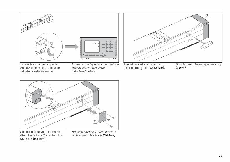
Tensar la cinta hasta que la visualización muestre el valor calculado anteriormente.
Increase the tape tension until the display shows the value calculated before.
Tras el tensado, apretar los tornillos de fijación SS (2 Nm).
Now tighten clamping screws SS (2 Nm).
�
��
Colocar de nuevo el tapón PF. Atornillar la tapa Q con tornillos M2.5 x 5 (0.6 Nm).
Replace plug PF. Attach cover Q with screws M2.5 x 5 (0.6 Nm).
34
�=�
@�=�
�
� �� ��
�=�
@�=�
�
� �� �� �
�
�����
)A��A�)���
��
����������
�
�
8
��-
����������
�
�
8
��-�2
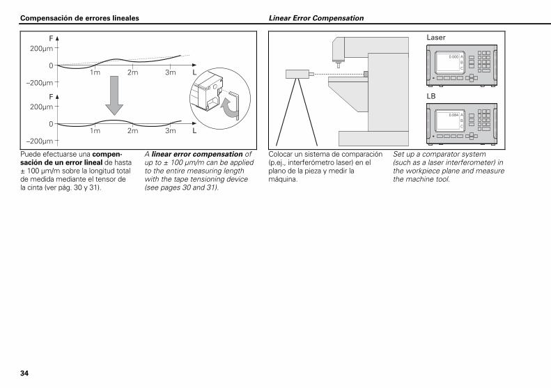
Puede efectuarse una compen-sación de un error lineal de hasta ± 100 µm/m sobre la longitud total de medida mediante el tensor de la cinta (ver pág. 30 y 31).
A linear error compensation of up to ± 100 µm/m can be applied to the entire measuring length with the tape tensioning device (see pages 30 and 31).
Colocar un sistema de comparación (p.ej., interferómetro laser) en el plano de la pieza y medir la máquina.
Set up a comparator system (such as a laser interferometer) in the workpiece plane and measure the machine tool.
Compensación de errores lineales Linear Error Compensation
35
A�
��B
9/
5;
5 =� 4�;5 � � 5 =�.�
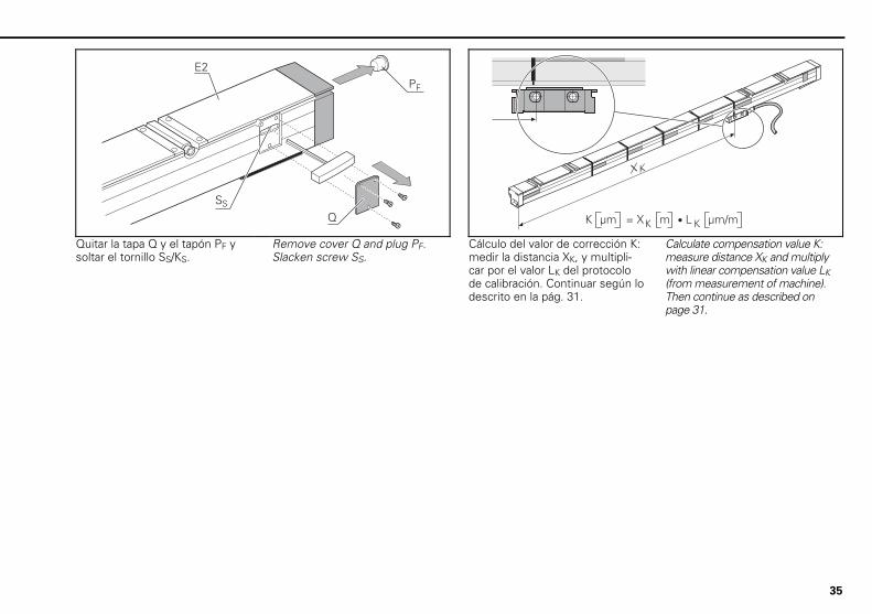
Quitar la tapa Q y el tapón PF y soltar el tornillo SS/KS.
Remove cover Q and plug PF. Slacken screw SS.
Cálculo del valor de corrección K: medir la distancia XK, y multipli-car por el valor LK del protocolo de calibración. Continuar según lo descrito en la pág. 31.
Calculate compensation value K: measure distance XK and multiply with linear compensation value LK (from measurement of machine). Then continue as described on page 31.
36
�����!�(��
(�@��$.����,�-��C�
,-���
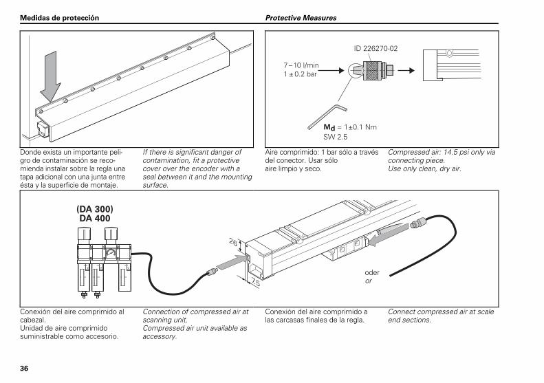
Donde exista un importante peli- gro de contaminación se reco-mienda instalar sobre la regla una tapa adicional con una junta entre ésta y la superficie de montaje.
If there is significant danger of contamination, fit a protective cover over the encoder with a seal between it and the mounting surface.
Aire comprimido: 1 bar sólo a través del conector. Usar sólo aire limpio y seco.
Compressed air: 14.5 psi only via connecting piece. Use only clean, dry air.
&�����"�����
Conexión del aire comprimido al cabezal. Unidad de aire comprimido suministrable como accesorio.
Connection of compressed air at scanning unit. Compressed air unit available as accessory.
Conexión del aire comprimido a las carcasas finales de la regla.
Connect compressed air at scale end sections.
Medidas de protección Protective Measures
oder or
37
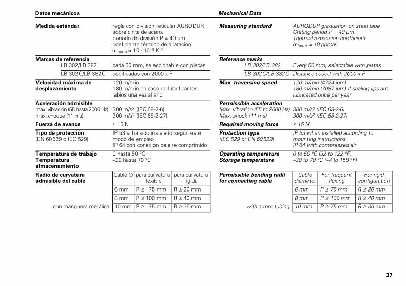
Medida estándar regla con división reticular AURODUR sobre cinta de acero. periodo de división P = 40 µm coeficiente térmico de dilatación therm 10 · 10–6 K–1
Measuring standard AURODUR graduation on steel tape Grating period P = 40 µm Thermal expansion coefficient therm 10 ppm/K
Marcas de referencia Reference marks LB 302/LB 382 cada 50 mm, seleccionable con placas LB 302/LB 382 Every 50 mm, selectable with plates
LB 302C/LB 382C codificadas con 2000 x P LB 302C/LB 382C Distance-coded with 2000 x P
Velocidad máxima de desplazamiento
120 m/min 180 m/min en caso de lubrificar los labios una vez al año
Max. traversing speed 120 m/min (4724 ipm) 180 m/min (7087 ipm) if sealing lips are lubricated once per year
Aceleración admisible máx. vibración (55 hasta 2000 Hz) máx. choque (11 ms)
300 m/s2 (IEC 68-2-6) 300 m/s2 (IEC 68-2-27)
Permissible acceleration Max. vibration (55 to 2000 Hz) Max. shock (11 ms)
300 m/s2 (IEC 68-2-6) 300 m/s2 (IEC 68-2-27)
Fuerza de avance 15 N Required moving force 15 N
Tipo de protección (EN 60529 o IEC 529)
IP 53 si ha sido instalado según este modo de empleo IP 64 con conexión de aire comprimido
Protection type (IEC 529 or EN 60529)
IP 53 when installed according to mounting instructions IP 64 with compressed air
Temperatura de trabajo Temperatura almacenamiento
0 hasta 50 °C –20 hasta 70 °C
Operating temperature Storage temperature
0 to 50 °C (32 to 122 °F) –20 to 70 °C (–4 to 158 °F)
Radio de curvatura admisible del cable
Cable para curvatura flexible
para curvatura rígida
Permissible bending radii for connecting cable
Cable diameter
For frequent flexing
For rigid configuration
6 mm R 75 mm R 20 mm 6 mm R 75 mm R 20 mm
8 mm R 100 mm R 40 mm 8 mm R 100 mm R 40 mm
con manguera metálica 10 mm R 75 mm R 35 mm with armor tubing 10 mm R 75 mm R 35 mm
Datos mecánicos Mechanical Data
38
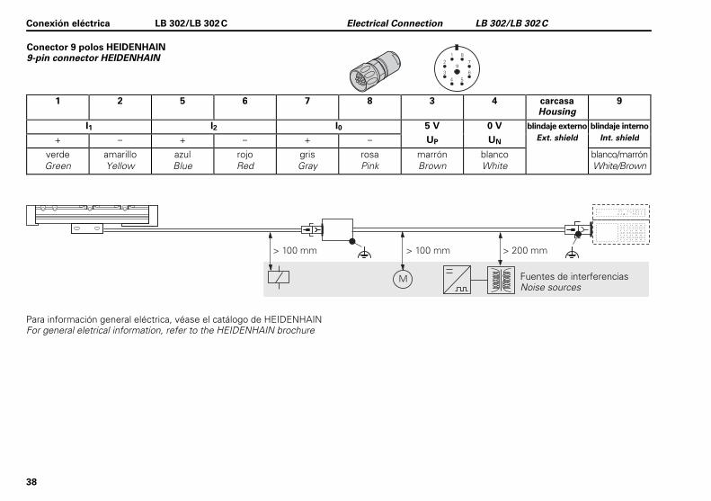
Conector 9 polos HEIDENHAIN 9-pin connector HEIDENHAIN
�
��
��
��
�
1 2 5 6 7 8 3 4 carcasa
Housing 9
I1 I2 I0 5 V 0 V blindaje externo blindaje interno
+ – + – + – UP UN Ext. shield Int. shield
verde Green
amarillo Yellow
azul Blue
rojo Red
gris Gray
rosa Pink
marrón Brown
blanco White
blanco/marrón White/Brown
Para información general eléctrica, véase el catálogo de HEIDENHAIN For general eletrical information, refer to the HEIDENHAIN brochure
Conexión eléctrica LB 302/LB 302C Electrical Connection LB 302/LB 302C
Fuentes de interferencias Noise sources
39
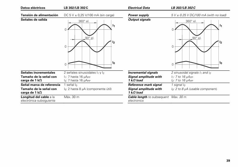
Tensión de alimentación DC 5 V ± 0,25 V/100 mA (sin carga) Power supply 5 V ± 0.25 V DC/100 mA (with no load) Señales de salida
��
��"� !
�
�
�
��
��
��"� !
Output signals
��
��"� !
�
�
�
��
��
��"� !
Señales incrementales 2 señales sinusoidales I1 y I2 Incremental signals 2 sinusoidal signals I1 and I2 Tamaño de la señal con carga de 1 k
I1: 7 hasta 16 µAPP I2: 7 hasta 16 µAPP
Signal amplitude with 1 k load
I1: 7 to 16 µAPP I2: 7 to 16 µAPP
Señal marca de referencia 1 señal I0 Reference mark signal 1 signal I0
Tamaño de la señal con carga de 1 k
I0: 2 hasta 8 µA (componente útil) Signal amplitude with 1 k load
I0: 2 to 8 µA (usable component)
Longitud del cable a la electrónica subsiguiente
Máx. 30 m Cable length to subsequent electronics
Max. 30 m
Datoa eléctricos LB 302/LB 302C Electrical Data LB 302/LB 302C
40
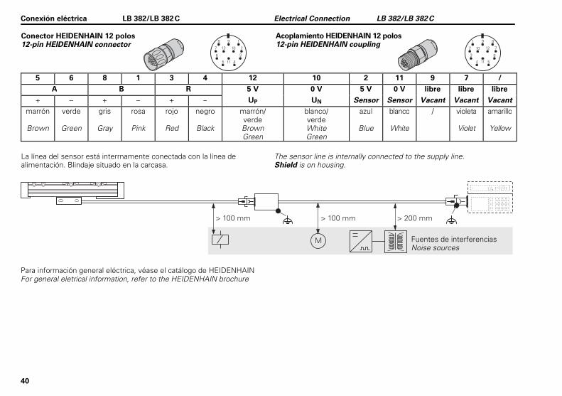
Conector HEIDENHAIN 12 polos 12-pin HEIDENHAIN connector
5 6 8 1 3 4 12 10 2 11 9 7 /
A B R 5 V 0 V 5 V 0 V libre libre libre + – + – + – UP UN Sensor Sensor Vacant Vacant Vacant
marrón
Brown
verde
Green
gris
Gray
rosa
Pink
rojo
Red
negro
Black
marrón/ verde Brown Green
blanco/ verde White Green
azul
Blue
blanco
White
/ violeta
Violet
amarillo
Yellow
La línea del sensor está interrnamente conectada con la línea de alimentación. Blindaje situado en la carcasa.
The sensor line is internally connected to the supply line. Shield is on housing.
Para información general eléctrica, véase el catálogo de HEIDENHAIN For general eletrical information, refer to the HEIDENHAIN brochure
Conexión eléctrica LB 382/LB 382C Electrical Connection LB 382/LB 382C
Fuentes de interferencias Noise sources
Acoplamiento HEIDENHAIN 12 polos 12-pin HEIDENHAIN coupling
41
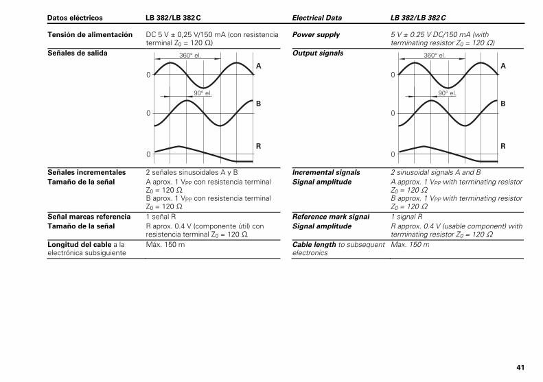
Tensión de alimentación DC 5 V ± 0,25 V/150 mA (con resistencia terminal Z0 = 120 )
Power supply 5 V ± 0.25 V DC/150 mA (with terminating resistor Z0 = 120 )
Señales de salida
Output signals
Señales incrementales 2 señales sinusoidales A y B Incremental signals 2 sinusoidal signals A and B Tamaño de la señal A aprox. 1 VPP con resistencia terminal
Z0 = 120 B aprox. 1 VPP con resistencia terminal Z0 = 120
Signal amplitude A approx. 1 VPP with terminating resistor Z0 = 120 B approx. 1 VPP with terminating resistor Z0 = 120
Señal marcas referencia 1 señal R Reference mark signal 1 signal R
Tamaño de la señal R aprox. 0.4 V (componente útil) con resistencia terminal Z0 = 120
Signal amplitude R approx. 0.4 V (usable component) with terminating resistor Z0 = 120
Longitud del cable a la electrónica subsiguiente
Máx. 150 m Cable length to subsequent electronics
Max. 150 m
Datos eléctricos LB 382/LB 382C Electrical Data LB 382/LB 382C

42

43

������������������������������������������������������������������������������������� �������������� ���������������������������������������
����������������� � ��������������������������������� � ����������������
��������������������������������������������������� � ����������������
������������������������������������������������������ � ����������������
��������������������������������������������������� � ����������������
����������������������������������������������� � ����������������
�������������������������������������������
�����������������
*I_673179-53*
673179-53 · Ver02 · Printed in Germany · 1/2013 · H