modelling of small capacity absorption chillers driven by solar thermal energy or waste heat
TRANSCRIPT

MODELLING OF SMALL CAPACITY ABSORPTION CHILLERS DRIVEN BY
SOLAR THERMAL ENERGY OR WASTE HEAT Jerko Labus
Dipòsit Legal: T.1716-2011
ADVERTIMENT. La consulta d’aquesta tesi queda condicionada a l’acceptació de les següents condicions d'ús: La difusió d’aquesta tesi per mitjà del servei TDX (www.tesisenxarxa.net) ha estat autoritzada pels titulars dels drets de propietat intel·lectual únicament per a usos privats emmarcats en activitats d’investigació i docència. No s’autoritza la seva reproducció amb finalitats de lucre ni la seva difusió i posada a disposició des d’un lloc aliè al servei TDX. No s’autoritza la presentació del seu contingut en una finestra o marc aliè a TDX (framing). Aquesta reserva de drets afecta tant al resum de presentació de la tesi com als seus continguts. En la utilització o cita de parts de la tesi és obligat indicar el nom de la persona autora. ADVERTENCIA. La consulta de esta tesis queda condicionada a la aceptación de las siguientes condiciones de uso: La difusión de esta tesis por medio del servicio TDR (www.tesisenred.net) ha sido autorizada por los titulares de los derechos de propiedad intelectual únicamente para usos privados enmarcados en actividades de investigación y docencia. No se autoriza su reproducción con finalidades de lucro ni su difusión y puesta a disposición desde un sitio ajeno al servicio TDR. No se autoriza la presentación de su contenido en una ventana o marco ajeno a TDR (framing). Esta reserva de derechos afecta tanto al resumen de presentación de la tesis como a sus contenidos. En la utilización o cita de partes de la tesis es obligado indicar el nombre de la persona autora. WARNING. On having consulted this thesis you’re accepting the following use conditions: Spreading this thesis by the TDX (www.tesisenxarxa.net) service has been authorized by the titular of the intellectual property rights only for private uses placed in investigation and teaching activities. Reproduction with lucrative aims is not authorized neither its spreading and availability from a site foreign to the TDX service. Introducing its content in a window or frame foreign to the TDX service is not authorized (framing). This rights affect to the presentation summary of the thesis as well as to its contents. In the using or citation of parts of the thesis it’s obliged to indicate the name of the author.
Jerko Labus
Modelling of small capacity absorption
chillers driven by solar thermal energy
or waste heat
A thesis submitted in partial fulfillment of the requirements of
Rovira i Virgily University for the degree of Doctor of Philosophy
Supervised by: Dr. Alberto Coronas Salcedo
Dr. Joan Carles Bruno Arguilaget
Tarragona
2011
UNIVERSITAT ROVIRA I VIRGILI MODELLING OF SMALL CAPACITY ABSORPTION CHILLERS DRIVEN BY SOLAR THERMAL ENERGY OR WASTE HEAT Jerko Labus DL:T.1716-2011
Los abajo firmantes, Dr. Alberto Coronas, Catedrático de Universidad del Área
de Máquinas y Motores Térmicos y Dr. Joan Carles Bruno, Profesor Agregado, del
Departament d’Enginyeria Mecánica de la Universitat Rovira i Virgili de Tarragona
HACEN CONSTAR:
Que el trabajo titulado: “Modelling of Small Capacity Absorption Chillers Driven by
Solar Thermal Energy or Waste Heat” presentado por el Sr. Jerko Labus para optar al
grado de Doctor de la Universitat Rovira i Virgili, ha sido realizado bajo su dirección
inmediata en el CREVER – Grup de recerca d’Enginyeria Tèrmica Aplicada del
Departament d’Enginyeria Mecànica de la Universitat Rovira i Virgili, que todos los
resultados han sido obtenidos en las experiencias realizadas por dicho doctorando y que
cumple los requisitos para poder optar a la Mención Europea.
Y para que así conste a los efectos oportunos, firmamos este documento.
Tarragona, 09 de Septiembre de 2011.
UNIVERSITAT
ROVIRA I VIRGILI
DEPARTAMENT D’ENGINYERIA MECÀNICA
Escola Tècnica Superior d’Enginyeria Química (ETSEQ).
Av. Països Catalans 26. 43007 Tarragona (Spain)
UNIVERSITAT ROVIRA I VIRGILI MODELLING OF SMALL CAPACITY ABSORPTION CHILLERS DRIVEN BY SOLAR THERMAL ENERGY OR WASTE HEAT Jerko Labus DL:T.1716-2011

ii
UNIVERSITAT ROVIRA I VIRGILI MODELLING OF SMALL CAPACITY ABSORPTION CHILLERS DRIVEN BY SOLAR THERMAL ENERGY OR WASTE HEAT Jerko Labus DL:T.1716-2011
iii
Abstract
The current energy systems, mainly based on fossil fuels, are largely
responsible, among others, for the present environmental and economic crisis. The
electrical air-conditioning units are significant contributors to the primary energy
consumption. The continued rise in living as well as working comfort conditions,
coupled together with reduced prices of air-conditioning units and lower electricity
prices, have caused a great expansion of these systems. The consequence is the negative
impact on electricity demand and environment. Since absorption machines have a small
requirement for electrical power, electric utilities have promoted them as a measure of
reducing utility demand peaks. Another advantage of absorption units is that working
fluids are not harmful to the environment, unlike the CFC’s and HCFC’s refrigerants
used in compression units. Recently, there is a rising tendency in demand for small
capacity absorption machines, particularly for residential and small office applications.
However, high investment cost, requirement of additional equipment and only a few
manufacturers are main causes why these machines are not economically competitive
with conventional compression machines. Also, there is a lack of adequate standards,
best practice guides and test procedures for their evaluation. In order to overcome these
shortcomings, it is necessary to intensify the work in all important fields: starting from
design and experimental work, over modelling and control to their implementation in
complex air-conditioning systems.
This research deals with the development of the simple, yet accurate steady-state
models of small capacity absorption machines which are based on highly reliable data
obtained in the state-of-the-art test bench. These models can further be used in
simulation tools or to develop supervisory control strategies for air-conditioning
systems with absorption machines. Therefore, the main aim of this research is to
develop and to describe a comprehensive methodology which will enclose entire
process which consists of testing, modelling and control strategy development of small
capacity absorption machines.
To achieve this aim, the first task is to obtain highly reliable data. This task
required development of a simple test procedure based on existing knowledge and
UNIVERSITAT ROVIRA I VIRGILI MODELLING OF SMALL CAPACITY ABSORPTION CHILLERS DRIVEN BY SOLAR THERMAL ENERGY OR WASTE HEAT Jerko Labus DL:T.1716-2011
iv
experience. The final result is the procedure which contains several important steps: test
planning, data modelling, how to develop detector for steady-state conditions, the
uncertainty estimation and the analysis of the results.
The second part of the research is focused on the development of small capacity
absorption chiller models based on the obtained datasets. The study includes five
different modelling methods using both mechanistic and empirical approaches:
thermodynamic, adapted Gordon-Ng, adapted characteristic equation, multivariate
polynomial regression and artificial neural networks modelling. The results clearly
indicate that it is possible to develop highly accurate empirical models by using only the
variables of external water circuits as input parameters. The excellent statistical
indicators such as coefficient of determination (>0.99) and coefficient of variation
(<5%) confirm that. The study also describes statistical tests which might assist in
selection of the most appropriate model.
The last part of the research deals with supervisory control of small capacity
absorption chillers. Two optimal control strategies are developed to demonstrate how
advanced modelling and optimization methods such as Artificial Neural Networks
(ANN) and Genetic Algorithms (GA) can be implemented in on-line control of air-
conditioning systems with absorption chillers.
UNIVERSITAT ROVIRA I VIRGILI MODELLING OF SMALL CAPACITY ABSORPTION CHILLERS DRIVEN BY SOLAR THERMAL ENERGY OR WASTE HEAT Jerko Labus DL:T.1716-2011
v
Resumen
Los sistemas energéticos basados en combustibles fósiles se encuentran entre los
principales responsables de la situación ambiental y crisis económica que afectan al
mundo en estos momentos, siendo los equipos tradicionales de aire acondicionado uno
de los mayores consumidores de energía primaria. Estos sistemas han logrado ocupar un
nicho muy importante en la vida cotidiana debido al incremento en la demanda de
confort, en el reducido coste de estos equipos y a las bajas tarifas eléctricas; pero
también han llevado a que se produzcan impactos negativos tanto en la demanda
eléctrica como a nivel medioambiental. Una solución a estos sistemas es el uso de
máquinas de absorción debido a que su bajo consumo eléctrico permitiría reducir los
picos de demanda de las generadoras eléctricas. Otra ventaja de las máquinas de
absorción es el uso de mezclas de trabajo no perjudiciales para el medio ambiente como
sí lo son los refrigerantes utilizados en las máquinas de compresión (CFCs y HCFCs).
En los últimos años se ha dado un incremento en el uso de máquinas de absorción de
pequeña potencia especialmente en el sector residencial y en pequeñas oficinas; sin
embargo, sus elevados costes junto a la necesidad de equipo adicional y al reducido
número de fabricantes han propiciado que estas máquinas no sean económicamente
competitivas con las máquinas convencionales de compresión. Además a esto hay que
sumar la falta de estándares adecuados, guías de mejores prácticas y procedimientos de
ensayos para su evaluación. Para superar estas deficiencias es necesario intensificar el
trabajo en todas las áreas importantes, comenzando desde el diseño y trabajo
experimental, pasando por el modelado y control hasta llegar a su implementación en
sistemas de aire acondicionado complejos.
Esta investigación se centra en el desarrollo de modelos en régimen estacionario
de máquinas de absorción de pequeña potencia basados en datos sumamente fiables
obtenidos en un banco de ensayos de última tecnología. Estos modelos pueden ser
utilizados más adelante en herramientas de simulación o para desarrollar estrategias de
control de supervisión en sistemas de aire acondicionado con máquinas de absorción. El
objetivo principal de esta investigación es por lo tanto desarrollar y describir una
metodología comprensiva que abarque los ensayos, el modelado y el desarrollo de
estrategias de control para máquinas de absorción de pequeña potencia.
UNIVERSITAT ROVIRA I VIRGILI MODELLING OF SMALL CAPACITY ABSORPTION CHILLERS DRIVEN BY SOLAR THERMAL ENERGY OR WASTE HEAT Jerko Labus DL:T.1716-2011
vi
Para lograr este objetivo, la primera tarea es obtener datos sumamente fiables
por lo que se requiere desarrollar un procedimiento simple de pruebas basado en
conocimiento y experiencia del banco de ensayos. El resultado final es un
procedimiento que contiene algunos pasos importantes como son: el planeamiento de
los ensayos o pruebas, el modelado de los datos, el saber detectar las condiciones de
estado estacionario, la evaluación de la incertidumbre y el análisis de los resultados.
La segunda parte de esta investigación se centra en el desarrollo de un modelo
de enfriadoras de absorción de pequeña potencia basado en resultados obtenidos
experimentalmente. Este estudio incluye cinco métodos de modelación con enfoques
tanto mecanicista como empírico: método termodinámico, método adaptado de Gordon-
Ng, método de la ecuación característica adaptada, método de regresión polinomial
multivariable y modelo de redes neuronales artificiales. Los resultados obtenidos
demuestran que es posible desarrollar modelos empíricos, altamente precisos, con tan
solo el uso de las variables de los circuitos de agua externos como parámetros de
entrada. Esta última aseveración se confirma con la obtención de indicadores
estadísticos tales como el coeficiente de determinación (>0.99) y el coeficiente de
variación (<5%). Además se describen pruebas estadísticas que podrían ser utilizadas al
momento de seleccionar el modelo más apropiado.
La última parte de esta investigación trata sobre el control de supervisión para
enfriadoras de absorción de pequeña potencia. Se han desarrollado dos estrategias de
control óptimas: la primera se encuentra basada en la modelación avanzada con Redes
Neuronales Artificiales (RNA), mientras que la segunda utiliza métodos de
optimización con Algoritmos Genéticos (AG). Se demuestra que estas dos estrategias
pueden ser implementadas para el control online de sistemas de aire acondicionado con
enfriadoras de absorción.
UNIVERSITAT ROVIRA I VIRGILI MODELLING OF SMALL CAPACITY ABSORPTION CHILLERS DRIVEN BY SOLAR THERMAL ENERGY OR WASTE HEAT Jerko Labus DL:T.1716-2011

vii
Acknowledgements
I would like to acknowledge financial support of this research which formed part
of the CITYNET project funded via the Marie Curie Research Training Network. Also,
special thanks go to all participants from the CITYNET project led by coordinator Dr.
Ursula Eicker, without whom this work would not have been possible.
I also happily acknowledge the contributions of many IESD Colleagues who
provided me with moral support and useful advices during my stage in the UK. I will
never forget the time spent in Leicester, long discussions on Friday and especially the
opportunity to work with Dr. Yi Zhang. I am honoured to have a person like you as a
friend. I also acknowledge the contribution of Dr. Alfredo Hernandez from UEAM,
Mexico who first introduced me to ANN modelling and worked with me on developing
the ANNi control methodology. I will never forget Dr. Mahmoud Bourouis, who was
suffering almost three years stacked in the same office with myself. Thank you for
understanding me.
I also happily acknowledge the contributions of all the Colleagues from URV
CREVER Group who sheared the good and the bad with me during this long four years.
Thank you all for support and help I received from you. Thanks also go to the whole
Department of the Mechanical engineering at URV for their assistance, especially to the
Secretary office.
Most of all I would like to acknowledge the contribution of my Colleagues, but
first friends, Ivan Korolija and Andres Montero. I would not get this thesis to the end
without you. Thank you for being friends and my moral support during this period. I
also use the opportunity to ask forgiveness from Miss Nuria Quince for all the teasing
she has suffered the last four years. You now that you are my friend.
Of course, many thanks go to my supervisors Dr. Alberto Coronas Salcedo and
Dr. Joan Carles Bruno. It may be said that I am not the easiest student to supervise, but
UNIVERSITAT ROVIRA I VIRGILI MODELLING OF SMALL CAPACITY ABSORPTION CHILLERS DRIVEN BY SOLAR THERMAL ENERGY OR WASTE HEAT Jerko Labus DL:T.1716-2011

viii
it seems that you have found the way to handle it. During the hard process of writing up
my thesis my requests for guidance were received with patience and generosity.
Finally, I use this opportunity to express my gratitude to my parents for all the
support and education they gave me. I am sorry that you are not here to share this
moment with me. Also, I want to acknowledge the support of my brother Peter, you
have always been my inspiration. So this is it. The PhD is finally finished. Now I can
get on with something else, finding new challenges and trying to make up the time to
my girlfriend and brother.
UNIVERSITAT ROVIRA I VIRGILI MODELLING OF SMALL CAPACITY ABSORPTION CHILLERS DRIVEN BY SOLAR THERMAL ENERGY OR WASTE HEAT Jerko Labus DL:T.1716-2011

ix
“We will either find a way, or make one”
Hannibal
UNIVERSITAT ROVIRA I VIRGILI MODELLING OF SMALL CAPACITY ABSORPTION CHILLERS DRIVEN BY SOLAR THERMAL ENERGY OR WASTE HEAT Jerko Labus DL:T.1716-2011

x
UNIVERSITAT ROVIRA I VIRGILI MODELLING OF SMALL CAPACITY ABSORPTION CHILLERS DRIVEN BY SOLAR THERMAL ENERGY OR WASTE HEAT Jerko Labus DL:T.1716-2011

xi
Dedicated to my parents and brother
UNIVERSITAT ROVIRA I VIRGILI MODELLING OF SMALL CAPACITY ABSORPTION CHILLERS DRIVEN BY SOLAR THERMAL ENERGY OR WASTE HEAT Jerko Labus DL:T.1716-2011

UNIVERSITAT ROVIRA I VIRGILI MODELLING OF SMALL CAPACITY ABSORPTION CHILLERS DRIVEN BY SOLAR THERMAL ENERGY OR WASTE HEAT Jerko Labus DL:T.1716-2011
xiii
Table of Contents
Abstract ........................................................................................................................... iii
Resumen ........................................................................................................................... v
Acknowledgements ........................................................................................................ vii
Table of Contents ......................................................................................................... xiii
List of Figures .............................................................................................................. xvii
List of Tables ................................................................................................................ xxi
Chapter 1 .......................................................... 1-1
Introduction .................................................................................................................. 1-1
1.1. Energy context .................................................................................................... 1-1
1.2. Background and motivation ............................................................................... 1-5
1.3. Aims and objectives ........................................................................................... 1-7
1.4. Research approach .............................................................................................. 1-8
1.5. Structure of the thesis ......................................................................................... 1-9
Chapter 2 .......................................................... 2-1
An overview on absorption technology ...................................................................... 2-1
2.1. Historical development ....................................................................................... 2-1
2.2. The basic principles of absorption cycle ............................................................ 2-3
2.3. Classification ...................................................................................................... 2-6
2.4. Working fluids .................................................................................................... 2-9
2.4.1. Water-Lithium Bromide (H2O-LiBr) ........................................................ 2-11
2.4.2. Ammonia-Water (NH3-H2O) .................................................................... 2-12
2.4.3. Ammonia-Lithium Nitrate (NH3-LiNO3) ................................................. 2-13
2.4.4. Water-Lithium Chloride (H2O-LiCl) ........................................................ 2-14
2.5. Configurations .................................................................................................. 2-15
2.5.1. Single-effect absorption chiller................................................................. 2-15
2.5.2. Double-effect absorption chiller ............................................................... 2-16
2.5.3. Triple-effect chiller ................................................................................... 2-18
2.5.4. Half-effect chiller...................................................................................... 2-18
2.5.5. GAX (Generator Absorber heat eXchanger) ............................................ 2-19
2.5.6. Heat pump ................................................................................................. 2-21
UNIVERSITAT ROVIRA I VIRGILI MODELLING OF SMALL CAPACITY ABSORPTION CHILLERS DRIVEN BY SOLAR THERMAL ENERGY OR WASTE HEAT Jerko Labus DL:T.1716-2011
xiv
2.5.7. Chiller/heater ............................................................................................ 2-21
2.6. Applications and trends .................................................................................... 2-21
2.7. Small capacity absorption machines - state of the art ...................................... 2-26
2.7.1. Commercial units ...................................................................................... 2-27
2.7.2. Research and development, prototypes .................................................... 2-28
2.7.3. Installations ............................................................................................... 2-34
2.8. Technology cost ............................................................................................... 2-37
2.9. Regulations and incentives ............................................................................... 2-40
2.10. Potential and barriers ...................................................................................... 2-42
Chapter 3 .......................................................... 3-1
Multifunctional test bench........................................................................................... 3-1
3.1. Introduction ........................................................................................................ 3-1
3.2. Absorption system standards .............................................................................. 3-3
3.3. AHRI/ANSI 560-2000 ....................................................................................... 3-4
3.4. EN 12309:2000 ................................................................................................ 3-10
3.5. Main components ............................................................................................. 3-16
3.6. Operating modes for absorption systems ......................................................... 3-22
3.6.1. Water-cooled absorption chiller ............................................................... 3-22
3.6.2. Air-cooled absorption chiller .................................................................... 3-25
3.6.3. Absorption heat-pump .............................................................................. 3-27
3.7. Data acquisition ................................................................................................ 3-29
3.8. Instrumentation ................................................................................................. 3-32
Chapter 4 .......................................................... 4-1
Testing the performance of absorption chillers ........................................................ 4-1
4.1. Introduction ........................................................................................................ 4-1
4.2. Stage one ............................................................................................................ 4-3
4.2.1. Rotartica Solar 045 ..................................................................................... 4-3
4.2.2. Measurement equipment and data acquisition system ............................... 4-7
4.2.3. Experimental procedure and test conditions ............................................... 4-8
4.2.4. Data modelling ........................................................................................... 4-9
4.2.5. Uncertainty estimation .............................................................................. 4-12
4.2.6. Results and Discussion ............................................................................. 4-13
UNIVERSITAT ROVIRA I VIRGILI MODELLING OF SMALL CAPACITY ABSORPTION CHILLERS DRIVEN BY SOLAR THERMAL ENERGY OR WASTE HEAT Jerko Labus DL:T.1716-2011
xv
4.3. Stage two .......................................................................................................... 4-17
4.3.1. Pink chilli PSC 12 ..................................................................................... 4-18
4.3.2. Measurement equipment and data acquisition system.............................. 4-19
4.3.3. Experimental procedure and test conditions ............................................. 4-19
4.3.4. Data modelling.......................................................................................... 4-20
4.3.5. Steady-state identification ........................................................................ 4-20
4.3.6. Uncertainty estimation .............................................................................. 4-21
4.3.7. Automation of the procedure .................................................................... 4-21
4.3.8. Results and Discussion ............................................................................. 4-22
4.4. Conclusions ...................................................................................................... 4-27
Chapter 5 .......................................................... 5-1
Modelling methods ....................................................................................................... 5-1
5.1. Introduction ........................................................................................................ 5-1
5.2. Database for modelling ...................................................................................... 5-4
5.3. Models ................................................................................................................ 5-4
5.3.1. Thermodynamic model (TD) ...................................................................... 5-4
5.3.2. Adapted Gordon-Ng model (GNA) ............................................................ 5-9
5.3.3. Adapted characteristic equation method DDt’ ......................................... 5-12
5.3.4. Multivariate Polynomial Regression (MPR) ............................................ 5-14
5.3.5. Artificial Neural Networks (ANN) ........................................................... 5-15
5.4. Results and discussion ...................................................................................... 5-17
5.4.1. Model parameters ..................................................................................... 5-17
5.4.2. Evaluation of the models .......................................................................... 5-21
5.5. Conclusions ...................................................................................................... 5-35
Chapter 6 .......................................................... 6-1
Optimal control ............................................................................................................ 6-1
6.1. Introduction ........................................................................................................ 6-1
6.2. Control strategies for absorption systems .......................................................... 6-2
6.3. Artificial Neural Network Inverse (ANNi) ...................................................... 6-14
6.3.1. ANN model ............................................................................................... 6-14
6.3.2. Optimal performance using ANNi............................................................ 6-15
6.4. Genetic Algorithm (GA) coupled with ANN ................................................... 6-21
UNIVERSITAT ROVIRA I VIRGILI MODELLING OF SMALL CAPACITY ABSORPTION CHILLERS DRIVEN BY SOLAR THERMAL ENERGY OR WASTE HEAT Jerko Labus DL:T.1716-2011
xvi
6.4.1. Case study ................................................................................................. 6-22
6.4.2. Load profile .............................................................................................. 6-23
6.4.3. Optimal control settings ............................................................................ 6-24
6.4.4. Results ...................................................................................................... 6-27
6.5. Conclusions ...................................................................................................... 6-29
Chapter 7 .......................................................... 7-1
Conclusions and Future Work .................................................................................... 7-1
7.1. Summary and conclusions .................................................................................. 7-1
7.2. Future work ........................................................................................................ 7-9
References .................................................................................................................... R-1
Papers by the Author .................................................................................................. L-1
Appendix A. Performance indicators ........................................................................ A-1
Appendix B. Uncertainty estimation ......................................................................... B-1
Appendix C. Steady state identification .................................................................... C-1
Appendix D. Test Results ........................................................................................... D-1
UNIVERSITAT ROVIRA I VIRGILI MODELLING OF SMALL CAPACITY ABSORPTION CHILLERS DRIVEN BY SOLAR THERMAL ENERGY OR WASTE HEAT Jerko Labus DL:T.1716-2011
xvii
List of Figures
Figure 1.1 World primary energy consumption [1] ....................................................... 1-1
Figure 1.2 World energy-related carbon dioxide emissions by fuel type [3]................. 1-2
Figure 1.3 World energy consumption in developed and developing countries [3] ..... 1-2
Figure 1.4 Energy consumption of buildings by sector on global level [6] .................. 1-3
Figure 1.5 EU-27 Breakdown of final energy consumption between sectors and final
electricity consumption in 2007 ......................................................................... 1-3
Figure 2.1 Compression and absorption refrigeration cycles......................................... 2-3
Figure 2.2 I and II law analysis of thermal cycles ......................................................... 2-4
Figure 2.3 Thermal cycles .............................................................................................. 2-4
Figure 2.4 Pressure-temperature diagram for H2O-LiBr (Duhring plot) ..................... 2-12
Figure 2.5 Single-effect absorption chiller................................................................... 2-15
Figure 2.6 Double-effect absorption chiller ................................................................. 2-17
Figure 2.7 Triple-effect absorption chiller ................................................................... 2-18
Figure 2.8 Half-effect absorption chiller ...................................................................... 2-19
Figure 2.9 GAX ............................................................................................................ 2-20
Figure 2.10 Energy flow of typical tri-generation system ........................................... 2-23
Figure 2.11 Number of installed solar cooling systems in a period 2004-2009 .......... 2-34
Figure 2.12 Percentage of use of different thermally driven technologies. ................. 2-35
Figure 2.13 The share of installed small capacity absorption chillers ......................... 2-35
Figure 2.14 Investment cost distribution for small solar cooling systems ................... 2-37
Figure 2.15 Cost distribution of the tri-generation system .......................................... 2-39
Figure 3.1 General scheme of the test bench ............................................................... 3-16
Figure 3.2 Test configuration for water-cooled absorption chiller .............................. 3-22
Figure 3.3 Test configuration for water-cooled absorption chiller in extreme conditions
.......................................................................................................................... 3-24
Figure 3.4 Test configuration for air-cooled absorption chiller ................................... 3-26
Figure 3.5 Test configuration for air-cooled chiller with variable humidity ............... 3-27
Figure 3.6 Test configuration for air/water absorption heat pump .............................. 3-28
Figure 3.7 SCADA basic scheme ................................................................................ 3-29
Figure 3.8 HMI of the multifunctional test bench........................................................ 3-30
UNIVERSITAT ROVIRA I VIRGILI MODELLING OF SMALL CAPACITY ABSORPTION CHILLERS DRIVEN BY SOLAR THERMAL ENERGY OR WASTE HEAT Jerko Labus DL:T.1716-2011
xviii
Figure 3.9 Control of the operational parameters through HMI .................................. 3-31
Figure 3.10 Trending chart for measured data ............................................................. 3-32
Figure 4.1 Rotartica Solar 045 and additional air-cooler for dry dissipation ................ 4-3
Figure 4.2 Rotary absorption assembly.......................................................................... 4-5
Figure 4.3 Volumetric flow rate vs. performance ........................................................ 4-13
Figure 4.4 Volumetric flow rate vs pressure drop ....................................................... 4-14
Figure 4.5 Chilled water outlet temperature vs. performance at Thw,in=90ºC .............. 4-15
Figure 4.6 Inlet chilled water temperature vs. performance HP .................................. 4-16
Figure 4.7 Pink chilli PSC 12....................................................................................... 4-18
Figure 4.8 Test procedure flowchart ............................................................................ 4-21
Figure 4.9 Volumetric flow rate vs. performance ........................................................ 4-22
Figure 4.10 Volumetric flow rate vs. pressure drop .................................................... 4-23
Figure 4.11 Chilled water outlet temperature vs. performance at Thw,in=85ºC ............ 4-24
Figure 4.12 Chilled water outlet temperature vs. performance at Thw,in=90ºC ............ 4-24
Figure 4.13 Chilled water outlet temperature vs. performance at Thw,in=100ºC .......... 4-25
Figure 4.14 Chilled fluid outlet temperature vs. performance at Thw,in=75ºC (EG) .... 4-26
Figure 4.15 Chilled fluid outlet temperature vs. performance at Thw,in=85ºC (EG) .... 4-26
Figure 4.16 Chilled fluid outlet temperature vs. performance at Thw,in=95ºC (EG) .... 4-27
Figure 5.1 SE absorption cycle- internal states .............................................................. 5-5
Figure 5.2 H2O-LiBr cycle with external heat flows ..................................................... 5-8
Figure 5.3 NH3-H2O cycle with external heat flows ...................................................... 5-8
Figure 5.4 ANN structure ............................................................................................. 5-16
Figure 5.5 ANN topology ............................................................................................ 5-19
Figure 5.6 Comparison of the catalogue and experimental data with data obtained by
simulation-Rotartica ......................................................................................... 5-22
Figure 5.7 Rotartica-cross validation of empirical models with experimental data from
Evola et al. (2010) ............................................................................................ 5-23
Figure 5.8 Comparison of the experimental data with data obtained by simulation-Pink
.......................................................................................................................... 5-24
Figure 5.9 Comparison between the measured and predicted evaporator and generator
loads-Rotartica ................................................................................................. 5-29
UNIVERSITAT ROVIRA I VIRGILI MODELLING OF SMALL CAPACITY ABSORPTION CHILLERS DRIVEN BY SOLAR THERMAL ENERGY OR WASTE HEAT Jerko Labus DL:T.1716-2011
xix
Figure 5.10 Comparison between the measured and predicted evaporator and generator
loads-Pink ......................................................................................................... 5-30
Figure 5.11 CV values-Pink ......................................................................................... 5-31
Figure 6.1 Control strategies for cooling water circuit ................................................ 6-10
Figure 6.2 Control through the hot water circuit ......................................................... 6-10
Figure 6.3 Control through the cooling water circuit ................................................... 6-11
Figure 6.4 ANNi - Case I ............................................................................................. 6-17
Figure 6.5 ANNi - Case II ............................................................................................ 6-19
Figure 6.6 Air-conditioning system with absorption chiller ........................................ 6-22
Figure 6.7 Daily profile for July 15 ............................................................................. 6-24
Figure 6.8 Model based optimal control with GA ....................................................... 6-25
Figure C.1 Moving window .......................................................................................... C-7
Figure C.2 Variation of flow rates during a start up test ............................................... C-9
Figure C.3 Variation of temperatures during a start up test ........................................ C-10
UNIVERSITAT ROVIRA I VIRGILI MODELLING OF SMALL CAPACITY ABSORPTION CHILLERS DRIVEN BY SOLAR THERMAL ENERGY OR WASTE HEAT Jerko Labus DL:T.1716-2011

UNIVERSITAT ROVIRA I VIRGILI MODELLING OF SMALL CAPACITY ABSORPTION CHILLERS DRIVEN BY SOLAR THERMAL ENERGY OR WASTE HEAT Jerko Labus DL:T.1716-2011
xxi
List of Tables
Table 2.1 Summary of working pairs for absorption systems ..................................... 2-10
Table 2.2 Summary of absorption cooling technology ................................................ 2-20
Table 2.3 Absorption chiller-solar collector matching ................................................ 2-22
Table 2.4 Absorption machines available in the market .............................................. 2-27
Table 2.5 Investment cost of small solar system in Italy ............................................. 2-38
Table 2.6 Investment cost of small solar system in the USA....................................... 2-38
Table 2.7 Investment cost of the tri-generation system in Bcn .................................... 2-39
Table 3.1 Environmental conditions and electrical power supply conditions ............. 3-13
Table 3.2 Rating test conditions for cooling capacity of chillers ................................. 3-13
Table 3.3 Rating test conditions for heat recovery capacity for chillers ...................... 3-14
Table 3.4 Permissible deviation from set values for chillers ....................................... 3-14
Table 3.5 Technical data for thermal oil heater Pirobloc GFT 010/20V ..................... 3-17
Table 3.6 Gas micro turbine Capstone C30 ................................................................. 3-18
Table 3.7 Plate heat exchangers Alfa Laval ................................................................. 3-18
Table 3.8 Dry cooler CIAT Europe 2 9032 HI 920 ..................................................... 3-19
Table 3.9 Environmental test chamber Telewig KZ/80 ............................................... 3-19
Table 3.10 Air handling unit CIATESA HYDRONIC AX M 45 CONFORT ........... 3-20
Table 3.11 Vapour compression chiller DYNACIAT LG 350V ................................ 3-20
Table 3.12 Hydraulic module CIAT MHJ 350 ........................................................... 3-21
Table 3.13 Instrumentation of the test bench ............................................................... 3-34
Table 4.1 Technical data for Rotartica Solar 045 .......................................................... 4-3
Table 4.2 Test conditions ............................................................................................. 4-15
Table 4.3 Technical data for Pink chilli PSC 12 .......................................................... 4-19
Table 5.1 Input parameters assuming pinch temperatures ............................................. 5-7
Table 5.2 Estimated input parameters for TD model-Rotartica ................................... 5-17
Table 5.3 Estimated input parameters for TD model-Pink .......................................... 5-18
Table 5.4 GNA model coefficients .............................................................................. 5-18
Table 5.5 Multiple linear regression fit parameters ......................................... 5-18
Table 5.6 Fitting coefficients for MPR models ............................................................ 5-19
Table 5.7 ANN coefficients-Rotartica ......................................................................... 5-20
UNIVERSITAT ROVIRA I VIRGILI MODELLING OF SMALL CAPACITY ABSORPTION CHILLERS DRIVEN BY SOLAR THERMAL ENERGY OR WASTE HEAT Jerko Labus DL:T.1716-2011
xxii
Table 5.8 ANN coefficients-Pink chilli12 ................................................................... 5-21
Table 5.9 Statistical indicators-Rotartica ..................................................................... 5-32
Table 5.10 Statistical indicators-Pink .......................................................................... 5-33
Table 5.11 AICc-Pink .................................................................................................. 5-34
Table 5.12 BIC-Pink .................................................................................................... 5-34
Table 6.1 Operating ranges .......................................................................................... 6-16
Table 6.2 Comparison ANNi vs. experimental data - Case I ....................................... 6-18
Table 6.3 Comparison ANNi vs. experimental data – Case II ..................................... 6-20
Table 6.4 Optimal control results ................................................................................. 6-28
Table B.1 Uncertainty budget for Qeva .......................................................................... B-1
Table B.2 Uncertainty budget for COPchiller,all............................................................... B-2
Table C.1 Permissible deviation from set values in steady- state conditions ............. C-11
Table D.1 Summary of the tests with Pink chilli 12 for fan-coil applications .............. D-1
Table D.2 Summary of the tests with Pink chilli 12 for fan-coil applications-
continuation ....................................................................................................... D-4
UNIVERSITAT ROVIRA I VIRGILI MODELLING OF SMALL CAPACITY ABSORPTION CHILLERS DRIVEN BY SOLAR THERMAL ENERGY OR WASTE HEAT Jerko Labus DL:T.1716-2011
1-1
Chapter 1
Introduction
“The great thing in the world is not so much where we stand,
as in what direction we are moving.”
Oliver Wendell Holmes
1.1. Energy context
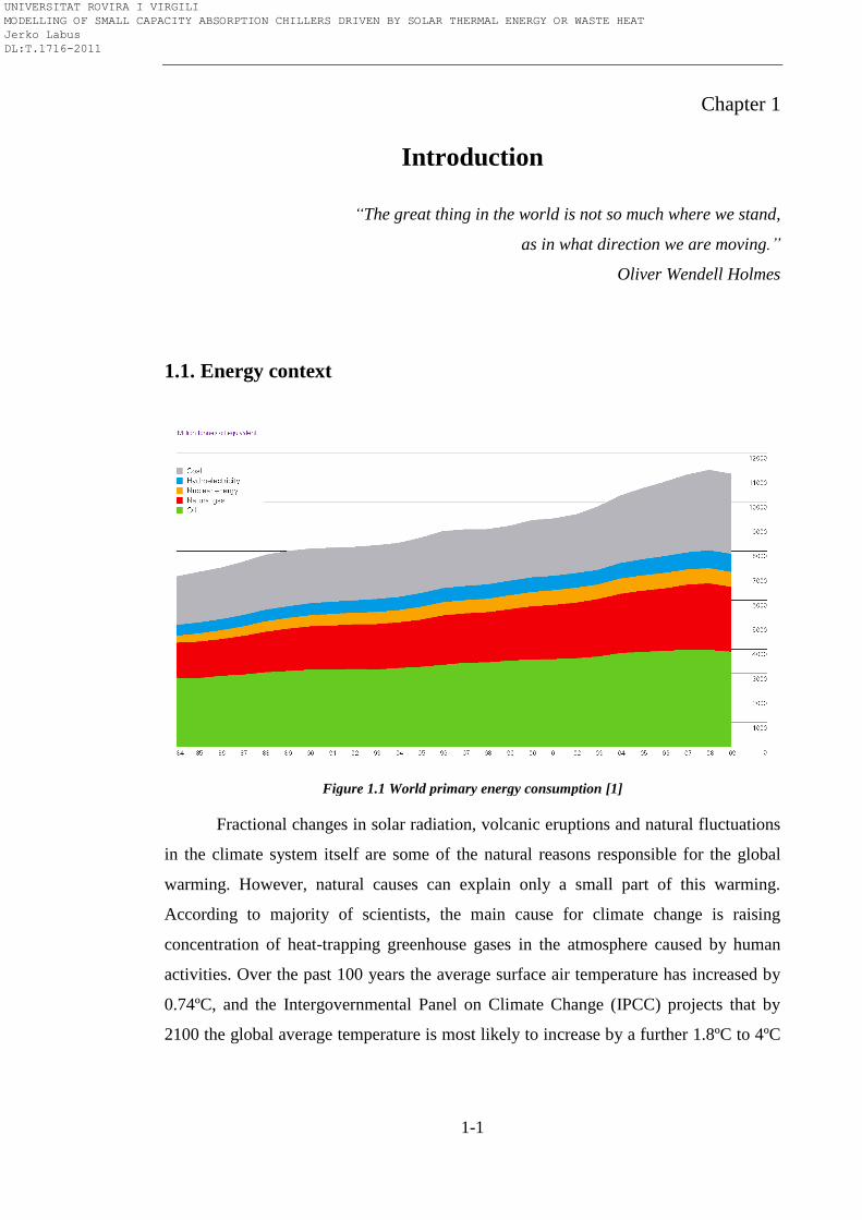
Figure 1.1 World primary energy consumption [1]
Fractional changes in solar radiation, volcanic eruptions and natural fluctuations
in the climate system itself are some of the natural reasons responsible for the global
warming. However, natural causes can explain only a small part of this warming.
According to majority of scientists, the main cause for climate change is raising
concentration of heat-trapping greenhouse gases in the atmosphere caused by human
activities. Over the past 100 years the average surface air temperature has increased by
0.74ºC, and the Intergovernmental Panel on Climate Change (IPCC) projects that by
2100 the global average temperature is most likely to increase by a further 1.8ºC to 4ºC
UNIVERSITAT ROVIRA I VIRGILI MODELLING OF SMALL CAPACITY ABSORPTION CHILLERS DRIVEN BY SOLAR THERMAL ENERGY OR WASTE HEAT Jerko Labus DL:T.1716-2011

Chapter 1
1-2
unless the world takes action to limit greenhouse gasses emissions [2]. The enhanced
effects of the global warming caused by intensive use of fossil fuels have already started
to affect our everyday lives and have severe consequences on Earth’s ecosystem.
Melting polar ice caps, higher seismic activity, hurricanes, retreating glaciers, rising sea
level, higher concentration of ozone in the lower atmosphere, extreme weather and
nature under risk are some of the consequences of the global warming. The economic
consequences are also visible such as the recent growth of the oil price in 2008 when the
oil prices overreached the level during the oil crisis in the seventies. Naturally expected
lack of the fossil fuel sources supported by actual economic crisis and by numerous
climate-related incidents will most likely increase the cost for energy even further.
World primary energy consumption decreased by 1.1% in 2009, which is the first
decline since 1982. Figure 1.1 illustrates primary energy consumption showing that oil
is still the world leading fuel while coal remains the fastest-growing fuel [1].
Figure 1.2 World energy-related carbon dioxide
emissions by fuel type [3]
Figure 1.3 World energy consumption in
developed and developing countries [3]
In response to rising concerns about climate change, world governments
gathered in Japanese town Kyoto adopted the protocol which identifies fiscal and
regulatory measures at local, national and international levels in order to begin the battle
to tackle climate change. The Kyoto protocol set the legally binding targets on
greenhouse gas emissions from industrialised countries. This protocol was only the first
step in the fight against climate change. Much more efforts and long-term commitments
have to be made by international community to avoid potentially disastrous impacts.
Rising carbon dioxide emission and prediction which is not promising (Figure 1.2) have
forced all major countries to intensify their efforts in this battle since the emissions
reduction commitment under the Kyoto protocol would not be enough. A crucial
UNIVERSITAT ROVIRA I VIRGILI MODELLING OF SMALL CAPACITY ABSORPTION CHILLERS DRIVEN BY SOLAR THERMAL ENERGY OR WASTE HEAT Jerko Labus DL:T.1716-2011
Introduction
1-3
element is that both developed and developing countries need to take the action. In
order to fight against climate change, EU adopted the climate and energy package in
2009 [4] which focuses on greenhouse gases cuts, increasing use of renewables and
improved energy efficiency. The package includes the amount of money which needs to
be invested in low-carbon development, innovative sources of international funding, an
international carbon market by 2015, and steps to help countries to adapt to climate
change.
The current energy systems, which are based on fossil fuels, are largely
responsible among others for the present environmental and economic crisis. A
significant contributor to the primary energy consumption of both developed and
developing countries are electrical air-conditioning units. The continued rise in living
and working comfort conditions with reduced prices of air-conditioning units and lower
electricity prices have caused a great expansion of these systems. Worldwide sales of
room air-conditioners are rapidly growing [5]. The consequence is the negative impact
on electricity demand and environment. Projected cooling and heating energy demands
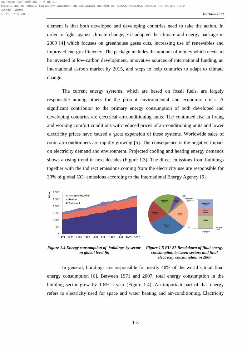
shows a rising trend in next decades (Figure 1.3). The direct emissions from buildings
together with the indirect emissions coming from the electricity use are responsible for
30% of global CO2 emissions according to the International Energy Agency [6].
Figure 1.4 Energy consumption of buildings by sector
on global level [6]
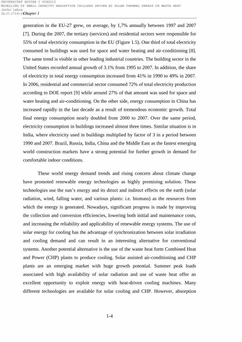
Figure 1.5 EU-27 Breakdown of final energy
consumption between sectors and final
electricity consumption in 2007
In general, buildings are responsible for nearly 40% of the world’s total final
energy consumption [6]. Between 1971 and 2007, total energy consumption in the
building sector grew by 1.6% a year (Figure 1.4). An important part of that energy
refers to electricity used for space and water heating and air-conditioning. Electricity
Transport32.06%
Industry19.35%
Residential18.63%
Services5.6%
Other1.22%
Agriculture2.02%
Residential28.6%
Services26.66%
Industry40.44%
Transport2.5%
Agriculture1.8%
Electricity21.12%
UNIVERSITAT ROVIRA I VIRGILI MODELLING OF SMALL CAPACITY ABSORPTION CHILLERS DRIVEN BY SOLAR THERMAL ENERGY OR WASTE HEAT Jerko Labus DL:T.1716-2011
Chapter 1
1-4
generation in the EU-27 grew, on average, by 1,7% annually between 1997 and 2007
[7]. During the 2007, the tertiary (services) and residential sectors were responsible for
55% of total electricity consumption in the EU (Figure 1.5). One third of total electricity
consumed in buildings was used for space and water heating and air-conditioning [8].
The same trend is visible in other leading industrial countries. The building sector in the
United States recorded annual growth of 3.1% from 1995 to 2007. In addition, the share
of electricity in total energy consumption increased from 41% in 1990 to 49% in 2007.
In 2006, residential and commercial sector consumed 72% of total electricity production
according to DOE report [9] while around 27% of that amount was used for space and
water heating and air-conditioning. On the other side, energy consumption in China has
increased rapidly in the last decade as a result of tremendous economic growth. Total
final energy consumption nearly doubled from 2000 to 2007. Over the same period,
electricity consumption in buildings increased almost three times. Similar situation is in
India, where electricity used in buildings multiplied by factor of 3 in a period between
1990 and 2007. Brazil, Russia, India, China and the Middle East as the fastest emerging
world construction markets have a strong potential for further growth in demand for
comfortable indoor conditions.
These world energy demand trends and rising concern about climate change
have promoted renewable energy technologies as highly promising solution. These
technologies use the sun’s energy and its direct and indirect effects on the earth (solar
radiation, wind, falling water, and various plants: i.e. biomass) as the resources from
which the energy is generated. Nowadays, significant progress is made by improving
the collection and conversion efficiencies, lowering both initial and maintenance costs,
and increasing the reliability and applicability of renewable energy systems. The use of
solar energy for cooling has the advantage of synchronization between solar irradiation
and cooling demand and can result in an interesting alternative for conventional
systems. Another potential alternative is the use of the waste heat form Combined Heat
and Power (CHP) plants to produce cooling. Solar assisted air-conditioning and CHP
plants are an emerging market with huge growth potential. Summer peak loads
associated with high availability of solar radiation and use of waste heat offer an
excellent opportunity to exploit energy with heat-driven cooling machines. Many
different technologies are available for solar cooling and CHP. However, absorption
UNIVERSITAT ROVIRA I VIRGILI MODELLING OF SMALL CAPACITY ABSORPTION CHILLERS DRIVEN BY SOLAR THERMAL ENERGY OR WASTE HEAT Jerko Labus DL:T.1716-2011
Introduction
1-5
systems are by far the dominating technology which has been applied in numerous
applications.
1.2. Background and motivation
Absorption machines1 provide opportunities for energy saving because they can
use heat to produce cooling (or heating, if necessary), instead of electricity used by
conventional compression machines. They are based on sorption process where a liquid
or solid sorbent absorbs refrigerant molecules into its inside and changes physically and
chemically in the process. Physical or chemical attraction between a pair of substances
is used to produce cooling effect. Thermal energy is directly transformed into cooling
power, and therefore, shaft power is not required. In this way, where power is expensive
or unavailable or where is solar, waste, gas, geothermal or heat available, absorption
machine provide reliable and noise-free cooling. Another advantage of absorption
machines is that they use environmentally friendly working fluid pairs which do not
deplete the ozone layer of the atmosphere, contrary to most working fluids in
conventional compression machines. Absorption machines have been present at the
market for a long time. Commercially available absorption chillers range in capacity
from medium (50-300kW) to high (300kW and up). They have been successfully
implemented in a great number of large-scale solar cooling systems and CHP
applications for large commercial building and industrial applications. However, the
interest in small capacity absorption machines (less than 50kW, especially less than
20kW) has started growing in the last two decades with concern about the environment
and increasing cooling demand in residential and small size office applications. The
initiative which began with the International Energy Agency (IEA) Task 25 [10] and
continued with IEA Task 38 [11] has given the results and today we have few small
capacity absorption units released to the market. The market potential for small-scale
cooling systems with absorption chillers is very large, but the full potential of these
systems is far from being realised. Despite the economic advantage of solar cooling and
CHP systems, which results from much lower operation costs (power, water and
maintenance) and reduced CO2 emission, there are many flaming issues to be solved in
order to be profitable and competitive to the conventional compression systems. The
1 Term ―absorption machines‖ refers to both absorption chilers and absorption heat pumps
UNIVERSITAT ROVIRA I VIRGILI MODELLING OF SMALL CAPACITY ABSORPTION CHILLERS DRIVEN BY SOLAR THERMAL ENERGY OR WASTE HEAT Jerko Labus DL:T.1716-2011
Chapter 1
1-6
results obtained during the monitoring of around 150 small-scale solar cooling systems
based on absorption within IEA Task 38 and the study of Henning [12] gave some
experience and hints for improvements. Field data and experience gained from
installations under real operating conditions have shown that there are frequent
shortcomings in the system’s hydraulic design as well as with the control. The design
phase for these systems requires a greater effort than a conventional system for the same
application. That often requires computer simulations of different system configurations
in order to identify the one with the best energy-cost performance. Also, special care has
to be given to the electrical consumption of the auxiliary equipment. A control strategy
of the absorption machine is maybe the most delicate issue. It often requires
sophisticated control to increase overall performance. Thus, improvements in the
performance of these thermally driven machines play a key role in order to approach
economic feasibility.
Bearing in mind that small-scale commercial absorption machines are still the
technology in its infancy, there is a lack of adequate standards, best practice guidelines
and test procedures for their evaluation which exist in the case of conventional
compression machines. The manufacturer catalogues often provide very poor
information about the absorption machine’s performance. Performing a comprehensive
performance analysis based on real operating data is still the best method for their
evaluation. This is the main reason why experimental work with this equipment in
appropriately equipped and monitored test facilities is essential for their further
improvement. Sometimes, the machine assembly does not permit access to internal
parameters, and performance should be analysed by measured parameters of external
circuits. On the other hand, almost all experimental works are based on analogy with
large-scale absorption systems, compression systems or on researcher’s experience.
Besides, trends toward improved system energy efficiency have changed, depending on
the actual conditions for specific applications. Therefore, there is a need for
methodology which would comprehend all the knowledge collected in this field. This
methodology should cover all important steps necessary for efficient experimental work
and data analysis in order to obtain a complete performance map of small capacity
absorption machine. The experimental data are the first important step for obtaining
precise and reliable mathematical models which are crucial for further development.
UNIVERSITAT ROVIRA I VIRGILI MODELLING OF SMALL CAPACITY ABSORPTION CHILLERS DRIVEN BY SOLAR THERMAL ENERGY OR WASTE HEAT Jerko Labus DL:T.1716-2011
Introduction
1-7
The importance of modelling was emphasized by several authors [13, 14]. The
modelling allows engineers to assess different operating strategies of absorption
machines in order to find the most economic operating conditions and to develop
optimal ways of control in air-conditioning systems. Despite the fact that various
authors have reported the work on absorption chiller modelling [15-18], there is no a
reported study which would compare different modelling approaches as, for instance, in
paper reported on vapour compression chiller modelling [19]. A comprehensive study
which considers the both physical and empirical modelling approaches, compares the
differences and provides a guideline for further use of the models.
With respect to all the facts stated above, this thesis contributes important
knowledge and methods for performance evaluation and modelling of small capacity
commercial absorption equipment when only external measurements are accessible.
This is an important issue for integrating this kind of equipment in systems which
reduce energy consumption and provide environmental benefits in residential and light
commercial buildings. Different modelling approaches developed in this thesis will help
software developers to find suitable method to simulate the interaction of the absorption
machine with other parts of a system: energy supply side, heat rejection side and chilled
water distribution side with different indoor air conditions and various load profiles.
The thesis aims to give assistance to overcome shortcomings such as insufficient system
design and control strategy selection of this innovative and promising technology.
1.3. Aims and objectives
The aim of this thesis is to produce a comprehensive methodology of testing, modelling
and control strategy development for small capacity absorption machines. Reliable and
accurate test dataset allows development of several mathematical models, which
describe small capacity absorption machine behaviour under various operating
conditions. These models can be further used for testing and validating different control
strategies as well as to provide the basis for optimizing the operation of absorption
machine in air-conditioning systems. The methods demonstrated in this thesis can be
widely used both in experimental work and in building energy system design.
UNIVERSITAT ROVIRA I VIRGILI MODELLING OF SMALL CAPACITY ABSORPTION CHILLERS DRIVEN BY SOLAR THERMAL ENERGY OR WASTE HEAT Jerko Labus DL:T.1716-2011
Chapter 1
1-8
In order to achieve this aim, the following objectives were defined:
• Comprehensive literature review on absorption technology and standards
with special care to small capacity absorption machines and their integration in solar-
assisted air-conditioning systems and micro-CHP systems
• Literature review on different modelling approaches applicable to
absorption machines and possible control strategies
• To develop simple procedure for testing small-scale commercial
absorption equipment which can provide complete performance evaluation of the same
based only on the external measurements
• To choose and install small-capacity commercial absorption unit in a
state-of-the-art test bench. The experimental results of the absorption unit will also
serve to validate this novel test bench
• To establish a simple analytical procedure to assess the performance of
the absorption machines based on the collected data, by using previous research works
and experience in this field
• To develop a data-filter which detects when absorption machine operates
in steady-state regime based on statistical approach and relevant standards
• Estimation of uncertainty in measurements
• To develop various steady-state models based on experimental results
using both physical and empirical approaches: from thermodynamic modelling to grey
and black box models
• To develop optimal control strategies based on these models which can
be implemented in on-line control systems
1.4. Research approach
To achieve research objectives, this thesis focuses on equipment installation and
test in an state-of-the-art test facility, data analysis, model development and
UNIVERSITAT ROVIRA I VIRGILI MODELLING OF SMALL CAPACITY ABSORPTION CHILLERS DRIVEN BY SOLAR THERMAL ENERGY OR WASTE HEAT Jerko Labus DL:T.1716-2011
Introduction
1-9
development of optimal control strategies using novel approaches such as Artificial
Neural Networks (ANN) and Genetic Algorithms (GA). Experimental data and
computational models are two basic components of this work. The experience gained
during the PhD period has been transformed in a form of specific guideline for other
researchers in this area, as a step by step procedure from test planning through
experimental work, data analysis to model and control strategy developments where the
final product can be useful for simulation software developers or control engineers.
1.5. Structure of the thesis
This thesis is divided into seven Chapters and three Appendixes where each
Chapter is written in a way that it also can be observed as a separate entity depending on
interest of future readers.
Chapter 1 describes the current energy situation and points out the main culprits
for the excessive consumption of primary energy and the negative impact on the
environment. The need for research in the field of small capacity absorption machines is
highlighted as a possible solution for conventional compression systems. The research
objectives have been selected and justified as well as the research approach which was
used to achieve these objectives.
Chapter 2 is an overview on absorption systems. The aim of this Chapter is to
help the reader to fully understand the absorption machines, their fundamental
principles and applications. A state of the art of small capacity absorption machines is
presented in the framework of the two most promising technologies: solar thermal and
Combined Cooling Heating and Power (CCHP). Based on comprehensive literature
review, Chapter 2 covers techno-economic aspects as well as the opportunities and
obstacles to further development of small capacity absorption machines.
Chapter 3 introduces a state of the art test bench as useful and necessary tool for
experimental work with small absorption machines. Based on existing standards for
absorption equipment and necessary instrumentation, this multifunctional test bench
provides a wide range of opportunities for testing in various applications under different
conditions. Different operating modes and required equipment are explained in detail.
UNIVERSITAT ROVIRA I VIRGILI MODELLING OF SMALL CAPACITY ABSORPTION CHILLERS DRIVEN BY SOLAR THERMAL ENERGY OR WASTE HEAT Jerko Labus DL:T.1716-2011
Chapter 1
1-10
Chapter 4 deals with the testing procedures for small capacity absorption
machines, in particular with commercial units and prototypes. This is an attempt of
creating standard procedure based on previous achievements and experience in this field
in order to create the complete performance map of the absorption machine by having
only external measurements and to generate database for absorption machine modelling.
Illustrated with examples of two commercial absorption units, this procedure is a step
by step guide that covers data analysis, development of a steady-state regime detector
and estimation of uncertainties.
Chapter 5 deals with modelling of small capacity absorption units based on
experimental database. Five different models have been developed using both physical
and empirical methods. Models are discussed in detail and evaluated through the prism
of statistical parameters. Special attention is given to ANN modelling.
Chapter 6 is addressed to the control issues of small capacity absorption
machines. This Chapter shows how developed models can be used for development of
different control strategies which can be implemented in on-line operations. Optimal
control was demonstrated by implementing optimization methods such as Nelder-Mead
simplex algorithm and genetic algorithms.
Chapter 7 summarizes all the results and work done in this thesis providing the
perspective for future research at the same time.
Appendix A lists the additional indicators which can be used to evaluate the
performance of absorption machines.
Appendix B presents the detailed explanation of uncertainty analysis procedure.
Appendix C contains the tables with detailed test results.
UNIVERSITAT ROVIRA I VIRGILI MODELLING OF SMALL CAPACITY ABSORPTION CHILLERS DRIVEN BY SOLAR THERMAL ENERGY OR WASTE HEAT Jerko Labus DL:T.1716-2011
2-1
Chapter 2
An overview on absorption technology
“Without continual growth and progress, such words as improvement,
achievement, and success have no meaning.”
Benjamin Franklin
2.1. Historical development
The roots of absorption technology can be traced to the mid of 17th
century and
the works of Dr. William Cullen and Nairne, as indicated in the comprehensive study of
Burgett et al. [20]. In the year 1823, Michael Faraday demonstrated that absorption of
ammonia gas can be used for cold production. Faraday used U tube where the cooling
effect was produced on one side by evaporating the ammonia and absorbed by silver
nitrate on the other side. Twenty-two years after, Edmund Carre designed and sold a
water-sulphuric acid machine which was used for cooling a drinking water. Shortly
after, in the year 1851, his brother Ferdinand released to the market the first successful
ammonia-water absorption refrigeration system. Some years later, in 1862, Mignon and
Rouard built the first ammonia-water machine of continuum cycle. Subsequent years
brought numerous improvements but nothing so crucial until 1913 when Edmund
Altenkirch established the thermodynamics of binary mixtures in absorption. The work
of Altenkirch contributed to the rising interest and development of absorption
refrigeration systems in following years. The period between two World wars was
marked mostly by disclosures of two companies in the field of refrigeration: Electrolux
in Sweden and Servel in the USA. The period after the Second World War is known as
the Golden Age of Absorption, especially in the USA where the HVAC industry was
booming with respect to absorption machines. The use of LiBr-H2O as working pair,
new disclosures and fast development of large capacity single-effect absorption
machines, first by Carrier (1945) and then by other leading HVAC companies (Trane,
York, Worthington) contributed to the penetration of absorption technology on the US
market. The sale of absorption chillers reached their peak in 1969, with one quarter of
the US market (1000 sold units). Primarily the oil crisis in 1973 as well as the
UNIVERSITAT ROVIRA I VIRGILI MODELLING OF SMALL CAPACITY ABSORPTION CHILLERS DRIVEN BY SOLAR THERMAL ENERGY OR WASTE HEAT Jerko Labus DL:T.1716-2011
Chapter 2
2-2
development of higher efficient vapour compression equipment caused the sharp fall of
interest for the absorption technology, leaving the share of annual sales in the USA on
the sidelines. On the other side of the globe, Japan started its post-war recovery. Faced
with shortage of its own natural energy resources and very expensive electricity
produced from Middle East oil, Japanese Government promoted natural gas as favoured
fuel. Japanese companies Kawasaki, Mitsubishi, Ebara, Sanyo, Hitachi and Yazaki
became aware of the possibility to improve efficiency of the absorption equipment by
using high temperature energy sources. The era of double-effect, indirect fired
absorption units have started in 1964, when Kawasaki released their unit to the market.
Further improvements of double-effect absorption machines and gas oriented policies
caused that large absorption equipment surpassed the electric chillers in 1975 for the
first time and a decade later, absorption chillers had more than 80% share of Japanese
large capacity market. The role of Japan as world leader in this field had a positive
impact on other countries in the Far East. Nowadays, India, China and Korea have a
very important role in the distribution of world market for absorption equipment. For
example, 6917 absorption chillers of around 12000 released to the market in 2005 were
manufactured in China [21]. Still, the share of absorption equipment in air-conditioning
and refrigeration is far from the share of conventional vapour compression equipment.
In the last three decades, after Montreal and especially after Kyoto protocol, the
interest in absorption equipment has become topical as a possible solution to the rising
concern of protecting the ozone layer. Environmental friendly fluids, as well as
possibility to use solar energy and waste heat make this equipment very interesting for
further research and development. The technological progress, particularly the progress
of solar collectors, has opened new horizons for absorption equipment. However, lots of
research efforts have to be done in order to make absorption equipment fully
competitive with conventional compression equipment in terms of both efficiency and
profitability.
UNIVERSITAT ROVIRA I VIRGILI MODELLING OF SMALL CAPACITY ABSORPTION CHILLERS DRIVEN BY SOLAR THERMAL ENERGY OR WASTE HEAT Jerko Labus DL:T.1716-2011

An overview on absorption technology
2-3
2.2. The basic principles of absorption cycle
The common approach to explain the absorption refrigeration cycle is by
comparing it with the more familiar vapour compression cycle. The working principle
of the absorption cycle is similar to that of the vapour compression cycle with two main
differences. The first difference is that absorption cycle is heat-driven thermal cycle,
where only thermal energy is exchanged with surroundings. No appreciable mechanical
energy is exchanged (or conversion of heat to work) as in the case of mechanical
compression cycle [22]. The second difference with respect to vapour compression
cycle is existence of secondary fluid in addition to the refrigerant, known as liquid
sorption medium or absorbent. Accordingly, the basic idea of absorption cycle is to
avoid compression work by using the suitable working pair: a refrigerant and a solution
which can absorb the refrigerant.
Figure 2.1 Compression and absorption refrigeration cycles
In the absorption cycle (Figure 2.1), the role of the mechanical compressor in
compression cycle is replaced by ―thermal compressor‖ which consists of generator,
absorber, solution heat exchanger, solution pump and throttling valve. Just like the
vapour compression cycle, the absorption cycle operates under two pressure levels.
High pressure level (refrigerant separation side) corresponds to the condenser-generator
QC
Refrigerant
liquid
Expansion
device
EQE
C QC
Refrigerant vapour
Refrigerant
liquid
Weak
absorbent
solution
Strong
absorbent
solution
Expansion
deviceSHX
P
QG
Refrigerant vapour
E AQE QA
C G
MC
Refrigerant vapour
Refrigerant vapour
Refrigerant
liquid+vapour
Refrigerant
liquid+vapour
W
Mechanical
compressor
"Thermal"
compressor
UNIVERSITAT ROVIRA I VIRGILI MODELLING OF SMALL CAPACITY ABSORPTION CHILLERS DRIVEN BY SOLAR THERMAL ENERGY OR WASTE HEAT Jerko Labus DL:T.1716-2011
Chapter 2
2-4
while low pressure level of absorption process in vacuum corresponds to evaporator-
absorber. The high pressure level is approximately ten times higher than low pressure
level in order to allow the heat rejection of the refrigerant at commonly available
temperatures. The working principle is based on different boiling temperatures of the
refrigerant and the absorbent. External heat input in the generator causes that refrigerant
is boiled out of a solution and compressed to the refrigeration vapour at higher pressure
while the concentrated absorbent stays liquid. The hot refrigerant vapour flows to the
condenser where heat is removed by external heat sink, condensing the refrigerant
vapour to liquid. The high-pressure liquid then passes through an expansion device
reducing its pressure to the evaporator pressure level. External heat input causes a
refrigerant to evaporate. The low pressure refrigerant vapour is then passed into the
absorber where it condenses diluting the concentrated absorbent coming from the
generator. The diluted solution (rich in refrigerant) is then pumped back to the generator
where it evaporates again, closing the cycle. In other words, the ―thermal‖ compressor
of the absorption cycle uses a heat-driven concentration difference to move refrigerant
vapour from the evaporator to the condenser.
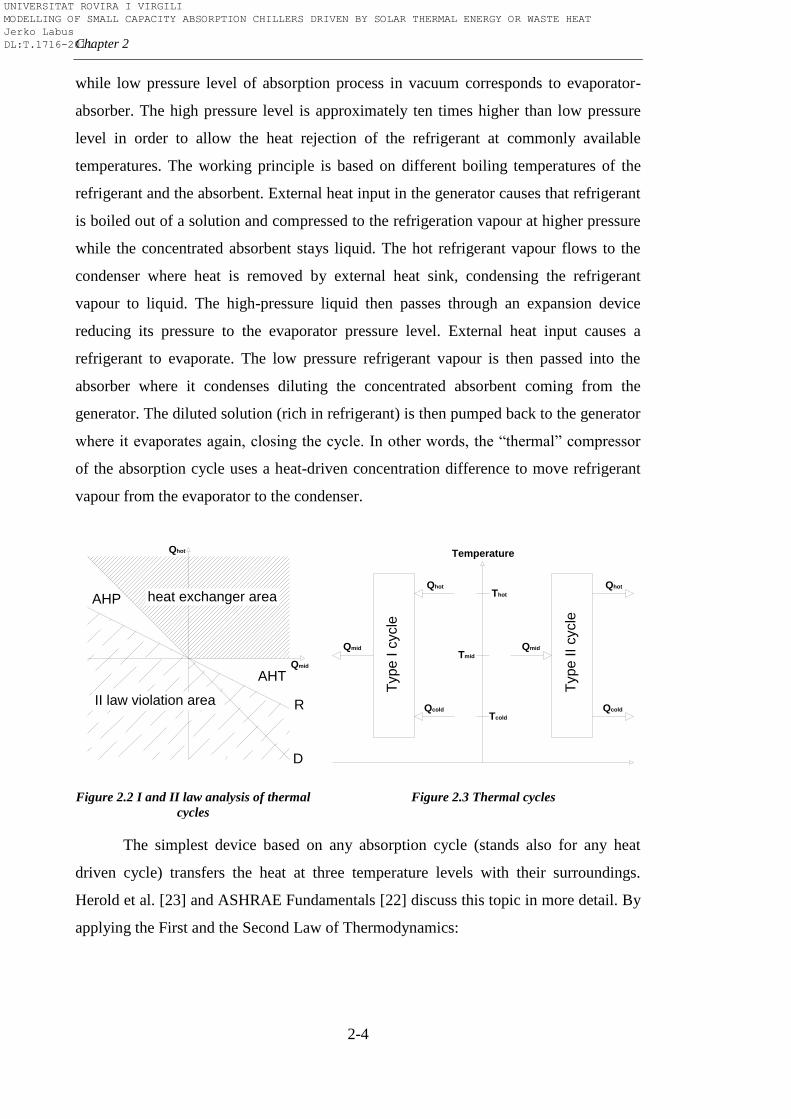
Figure 2.2 I and II law analysis of thermal
cycles
Figure 2.3 Thermal cycles
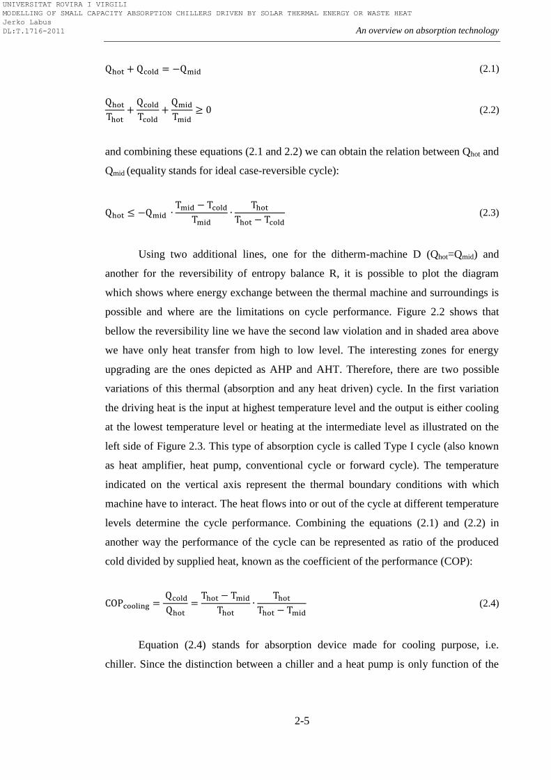
The simplest device based on any absorption cycle (stands also for any heat
driven cycle) transfers the heat at three temperature levels with their surroundings.
Herold et al. [23] and ASHRAE Fundamentals [22] discuss this topic in more detail. By
applying the First and the Second Law of Thermodynamics:
Qhot
AHT
AHP
II law violation area
heat exchanger area
Qmid
R
D
Qhot
Temperature
Thot
Tcold
Type
I c
ycle
Qcold
Qmid Qmid
Type
II
cycle
Qhot
Qcold
Tmid
UNIVERSITAT ROVIRA I VIRGILI MODELLING OF SMALL CAPACITY ABSORPTION CHILLERS DRIVEN BY SOLAR THERMAL ENERGY OR WASTE HEAT Jerko Labus DL:T.1716-2011
An overview on absorption technology
2-5
(2.1)
(2.2)
and combining these equations (2.1 and 2.2) we can obtain the relation between Qhot and
Qmid (equality stands for ideal case-reversible cycle):
(2.3)
Using two additional lines, one for the ditherm-machine D (Qhot=Qmid) and
another for the reversibility of entropy balance R, it is possible to plot the diagram
which shows where energy exchange between the thermal machine and surroundings is
possible and where are the limitations on cycle performance. Figure 2.2 shows that
bellow the reversibility line we have the second law violation and in shaded area above
we have only heat transfer from high to low level. The interesting zones for energy
upgrading are the ones depicted as AHP and AHT. Therefore, there are two possible
variations of this thermal (absorption and any heat driven) cycle. In the first variation
the driving heat is the input at highest temperature level and the output is either cooling
at the lowest temperature level or heating at the intermediate level as illustrated on the
left side of Figure 2.3. This type of absorption cycle is called Type I cycle (also known
as heat amplifier, heat pump, conventional cycle or forward cycle). The temperature
indicated on the vertical axis represent the thermal boundary conditions with which
machine have to interact. The heat flows into or out of the cycle at different temperature
levels determine the cycle performance. Combining the equations (2.1) and (2.2) in
another way the performance of the cycle can be represented as ratio of the produced
cold divided by supplied heat, known as the coefficient of the performance (COP):
(2.4)
Equation (2.4) stands for absorption device made for cooling purpose, i.e.
chiller. Since the distinction between a chiller and a heat pump is only function of the
UNIVERSITAT ROVIRA I VIRGILI MODELLING OF SMALL CAPACITY ABSORPTION CHILLERS DRIVEN BY SOLAR THERMAL ENERGY OR WASTE HEAT Jerko Labus DL:T.1716-2011
Chapter 2
2-6
application, the coefficient of performance for the absorption device with heating
purpose would be (2.5):
(2.5)
The second variation of the absorption thermal cycle is so-called Type II cycle
(also known as heat transformer, temperature amplifier, temperature booster or reverse
cycle), which is illustrated on the right side of Figure 2.3. The purpose of this cycle is to
use heat from intermediate temperature level to convert it to high temperature heat. At
the same time, as a consequence of the second law of thermodynamics, part of input
heat has to be rejected at lower temperature level. However, while Type I cycle have
found wide use in numerous HVAC and refrigeration application, with long existing
market for these equipment, Type II cycle have been demonstrated at laboratory level
and in pilot installations. Industrial applications with the absorption heat transformers
are very rare, and most of them can be found in Japanese industry [24].
2.3. Classification
The absorption machines can be classified based on several criteria: main
function, firing method, number of effects and stages, condensing method, working
fluids, application and capacity.
With respect to the main function, the absorption machines can be classified as:
Absorption chiller: to produce chilled water
Absorption chiller/heater: to produce chilled and hot water
Absorption heat pump: to produce hot water or steam by heat pump
action
Absorption heat transformer: to produce heat on higher temperature level
using the mid-temperature level as explained in Section 2.2
With respect to the firing method absorption machine can be:
UNIVERSITAT ROVIRA I VIRGILI MODELLING OF SMALL CAPACITY ABSORPTION CHILLERS DRIVEN BY SOLAR THERMAL ENERGY OR WASTE HEAT Jerko Labus DL:T.1716-2011
An overview on absorption technology
2-7
Indirect fired: driving heat is recovered from another process or heat
cycle machine. The driving heat to generator is normally delivered
through an intermediate element (heat exchanger). This heat in the form
of steam, hot liquid or hot exhausted gases is typically supplied by solar
collectors, district heating network, boiler, gas turbine or by some other
heat recovery device.
Direct fired: driving heat comes from combustion of fossil fuels. As a
result, these systems normally contain a liquid fuel or natural gas burner.
Within this classification, various subclasses can be made. Thus, depending on
the type of heat source exist: steam-driven, fuel-driven, exhaust gas-driven and hot
water-driven machine, etc. Also, a division on low, medium and high-grade heat
equipment can be made with respect to the activation temperature level in the generator.
In order to increase the efficiency, the basic absorption cycle which consists of
four basic components (generator, absorber, evaporator and condenser) can be extended
with one or more components at different pressures or concentrations. With respect to
the number and type of additional components, absorption machines can be categorized
by the number of effects or by the number of stages. According to terminology adopted
from Dorgan et al. [25], the term effect refers to the number of times the driving heat is
used by the absorption equipment, or simplified, the number of generators determines
the number of effects. In this way, we can distinguish between single-effect, double-
effect or triple-effect systems. Similarly, multistage absorption systems (single-stage,
double-stage or triple-stage) differ by the number of basic cycles (single-effect) that are
combined. Simplified, the number of evaporator/absorber pairs at different temperatures
in absorption machines determines the number of stages.
With respect to the employed condensation method (which fluid is used for heat
dissipation in the absorber and condenser), absorption machines can be classified to:
Air-cooled: the heat fluid is air and heat dissipation is normally realized
through an air-condenser. These equipment can also be indirect (heat
transfer from the absorber and condenser firstly to a closed water loop
UNIVERSITAT ROVIRA I VIRGILI MODELLING OF SMALL CAPACITY ABSORPTION CHILLERS DRIVEN BY SOLAR THERMAL ENERGY OR WASTE HEAT Jerko Labus DL:T.1716-2011
Chapter 2
2-8
and then to the ambient air) or direct (heat rejection directly to the
surroundings).
Water-cooled: the heat fluid is water and heat dissipation is normally
realized through a cooling tower.
Another classification is by the type of working pair used in the absorption
machine. The most common working pairs are water-lithium bromide (H2O-LiBr) and
ammonia-water (NH3-H2O) but there are also others which will be more discussed in
the following section.
Absorption machines can also be classified by working mode. The phases inside
the absorption cycle can be processed continuously or shifted periodically; and
therefore, we can distinguish between:
Continuous mode
Semi-continuous mode and
Discontinuous (batch) mode equipment.
With respect to the application purpose and based on cooling temperature
demand, absorption machines can be divided into three categories:
Space air-conditioning (7-18ºC)
Food and pharmaceutical storage refrigeration (0-7ºC)
Freezing (<0ºC) for ice-making or congelation.
Finally, absorption equipment (particularly absorption chillers) can be ranged
according to the produced cooling capacity:
Large-scale absorption chillers: cooling capacity higher than 300kW
Mid-scale absorption chillers: cooling capacity between 50 and 300kW
Small-scale absorption chillers: cooling capacity up to 50kW
UNIVERSITAT ROVIRA I VIRGILI MODELLING OF SMALL CAPACITY ABSORPTION CHILLERS DRIVEN BY SOLAR THERMAL ENERGY OR WASTE HEAT Jerko Labus DL:T.1716-2011
An overview on absorption technology
2-9
The last classification might look somewhat arbitrary since some authors move
the boundary for small-scale absorption chillers to 20kW and others to 30kW. Anyway,
the logical explanation would be that the classification is market dependant, i.e. depends
on the capacity of the units which can be found at the market.
2.4. Working fluids
The performance and efficiency of absorption systems is directly correlated with
the chemical, thermo physical and thermodynamic properties of the working fluid. A
margin of miscibility in liquid phase within the operating temperature range of the
absorption cycle is one of the fundamental requirements for suitable
absorbent/refrigerant combination. The suitability of the absorbent/refrigerant pairs is
determined by several necessary or desirable properties, which have been subject of
various studies in the past. A summary of these properties is given in following
paragraphs. It is preferable that the latent heat of the refrigerant is high in order to
minimize the circulation rate of the refrigerant and absorbent. Operating pressure of the
refrigerant should be moderate while for the absorbent operating pressure is
recommendable to be low. The refrigerant should have low freezing temperature and
should be much more volatile than the absorbent in order to separate them easily. The
refrigerant and absorbent should be chosen in a way to avoid solid phase over the
expected range of composition and temperature, otherwise, inappropriate choice can
cause operation shut down. Also, the chosen absorbent should have a strong affinity for
the refrigerant. High chemical stability is required to avoid unwanted formation of
gases, solids, or corrosive substances. Physical properties such as viscosity, surface
tension, density, thermal conductivity, specific heat capacity, heat of mixing and mass
diffusivity should be favourable for suitable selection of the working pair. Thus, low
viscosity increases heat and mass transfer and reduces pumping power. The low toxicity
of the working pair is another important parameter in order to avoid negative impact on
the environment. The care has to be taken with respect to corrosion and flammability,
too. However, the desirable properties are sometimes mutually exclusive and it is very
difficult (if not impossible) to find a working pair which fulfils all the requirements.
More precisely, it is a matter of compromise.
UNIVERSITAT ROVIRA I VIRGILI MODELLING OF SMALL CAPACITY ABSORPTION CHILLERS DRIVEN BY SOLAR THERMAL ENERGY OR WASTE HEAT Jerko Labus DL:T.1716-2011
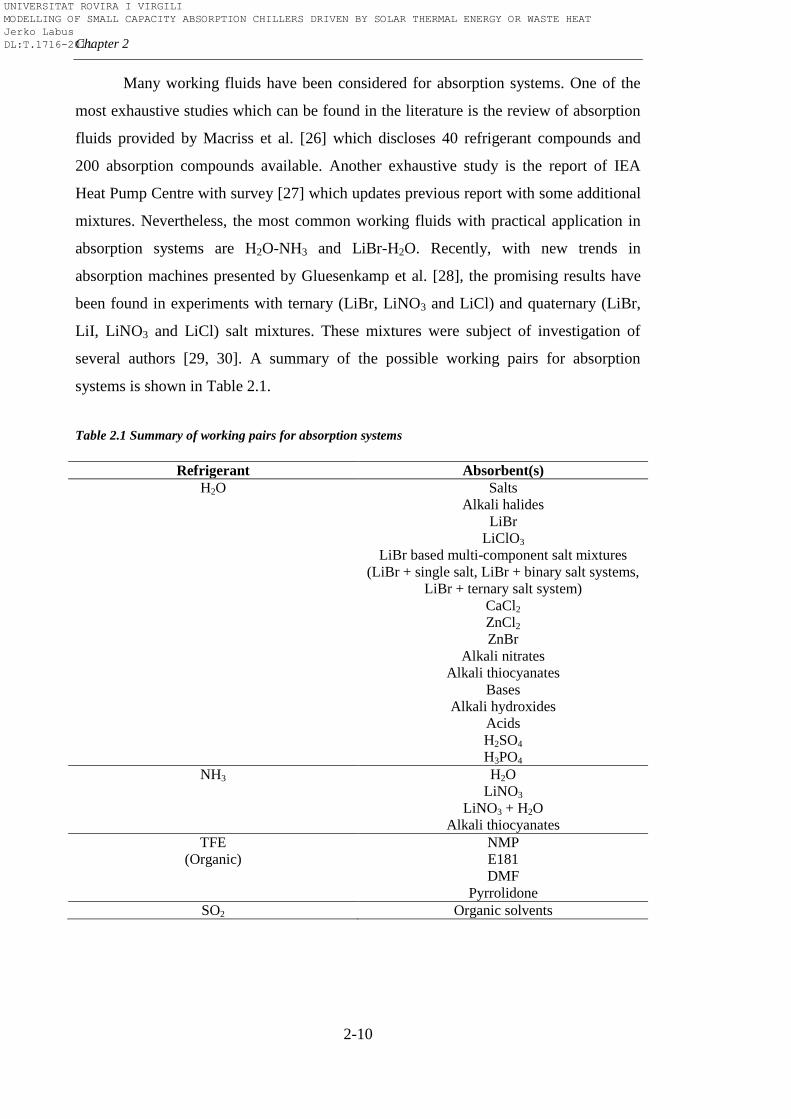
Chapter 2
2-10
Many working fluids have been considered for absorption systems. One of the
most exhaustive studies which can be found in the literature is the review of absorption
fluids provided by Macriss et al. [26] which discloses 40 refrigerant compounds and
200 absorption compounds available. Another exhaustive study is the report of IEA
Heat Pump Centre with survey [27] which updates previous report with some additional
mixtures. Nevertheless, the most common working fluids with practical application in
absorption systems are H2O-NH3 and LiBr-H2O. Recently, with new trends in
absorption machines presented by Gluesenkamp et al. [28], the promising results have
been found in experiments with ternary (LiBr, LiNO3 and LiCl) and quaternary (LiBr,
LiI, LiNO3 and LiCl) salt mixtures. These mixtures were subject of investigation of
several authors [29, 30]. A summary of the possible working pairs for absorption
systems is shown in Table 2.1.
Table 2.1 Summary of working pairs for absorption systems
Refrigerant Absorbent(s)
H2O Salts
Alkali halides
LiBr
LiClO3
LiBr based multi-component salt mixtures
(LiBr + single salt, LiBr + binary salt systems,
LiBr + ternary salt system)
CaCl2
ZnCl2
ZnBr
Alkali nitrates
Alkali thiocyanates
Bases
Alkali hydroxides
Acids
H2SO4
H3PO4
NH3 H2O
LiNO3
LiNO3 + H2O
Alkali thiocyanates
TFE NMP
(Organic) E181
DMF
Pyrrolidone
SO2 Organic solvents
UNIVERSITAT ROVIRA I VIRGILI MODELLING OF SMALL CAPACITY ABSORPTION CHILLERS DRIVEN BY SOLAR THERMAL ENERGY OR WASTE HEAT Jerko Labus DL:T.1716-2011
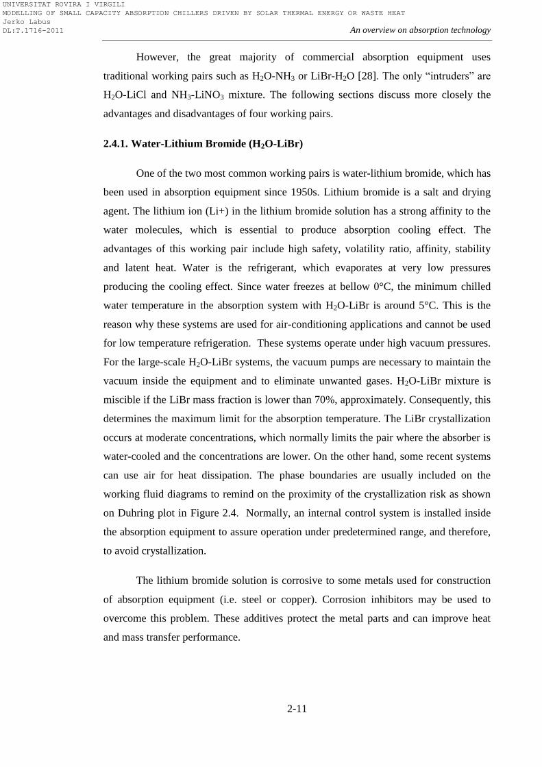
An overview on absorption technology
2-11
However, the great majority of commercial absorption equipment uses
traditional working pairs such as H2O-NH3 or LiBr-H2O [28]. The only ―intruders‖ are
H2O-LiCl and NH3-LiNO3 mixture. The following sections discuss more closely the
advantages and disadvantages of four working pairs.
2.4.1. Water-Lithium Bromide (H2O-LiBr)
One of the two most common working pairs is water-lithium bromide, which has
been used in absorption equipment since 1950s. Lithium bromide is a salt and drying
agent. The lithium ion (Li+) in the lithium bromide solution has a strong affinity to the
water molecules, which is essential to produce absorption cooling effect. The
advantages of this working pair include high safety, volatility ratio, affinity, stability
and latent heat. Water is the refrigerant, which evaporates at very low pressures
producing the cooling effect. Since water freezes at bellow 0°C, the minimum chilled
water temperature in the absorption system with H2O-LiBr is around 5°C. This is the
reason why these systems are used for air-conditioning applications and cannot be used
for low temperature refrigeration. These systems operate under high vacuum pressures.
For the large-scale H2O-LiBr systems, the vacuum pumps are necessary to maintain the
vacuum inside the equipment and to eliminate unwanted gases. H2O-LiBr mixture is
miscible if the LiBr mass fraction is lower than 70%, approximately. Consequently, this
determines the maximum limit for the absorption temperature. The LiBr crystallization
occurs at moderate concentrations, which normally limits the pair where the absorber is
water-cooled and the concentrations are lower. On the other hand, some recent systems
can use air for heat dissipation. The phase boundaries are usually included on the
working fluid diagrams to remind on the proximity of the crystallization risk as shown
on Duhring plot in Figure 2.4. Normally, an internal control system is installed inside
the absorption equipment to assure operation under predetermined range, and therefore,
to avoid crystallization.
The lithium bromide solution is corrosive to some metals used for construction
of absorption equipment (i.e. steel or copper). Corrosion inhibitors may be used to
overcome this problem. These additives protect the metal parts and can improve heat
and mass transfer performance.
UNIVERSITAT ROVIRA I VIRGILI MODELLING OF SMALL CAPACITY ABSORPTION CHILLERS DRIVEN BY SOLAR THERMAL ENERGY OR WASTE HEAT Jerko Labus DL:T.1716-2011
Chapter 2
2-12
Figure 2.4 Pressure-temperature diagram for H2O-LiBr (Duhring plot)
2.4.2. Ammonia-Water (NH3-H2O)
Ammonia-water working pair is one of the oldest working pairs, which has been
in use since the 18th
century. Ammonia as the refrigerant offers the opportunity to
operate with evaporating temperatures below 0ºC. Generally, ammonia-water is used for
refrigeration applications in the range from 5ºC down to -60ºC. It can also be used for
air-conditioning, but sometimes there are restrictions for use in building applications
because of risks associated with the use of ammonia. The preferred heat source
temperature for ammonia-water equipment is from 95ºC to 180ºC. The absorption
systems with this working pair operate at moderate pressure and no vacuum is required
till -30ºC. The advantage of this working pair is that ammonia is completely soluble in
water (at all concentrations), and therefore, there is no risk of crystallization. Another
benefit is that dry coolers can be easily applied in this case since the pressure in any part
of the ammonia-water absorption system is higher than atmospheric pressure. The
minimum pressure of the ammonia-water cycle is higher than 3 bars, and the pressure
drop is not as critical as in the case of other conventional fluids. This also allows the use
UNIVERSITAT ROVIRA I VIRGILI MODELLING OF SMALL CAPACITY ABSORPTION CHILLERS DRIVEN BY SOLAR THERMAL ENERGY OR WASTE HEAT Jerko Labus DL:T.1716-2011
An overview on absorption technology
2-13
of plate heat exchanges with extended surfaces and high heat transfer coefficients. This
further assures compact design with reduced ammonia charge, and consequently,
increased safety of the absorption system. On the other hand, operation at high pressures
(in particular the pressure of high temperature generator) is the main reason why there
are no double-effect absorption systems with ammonia-water. Also, ammonia is both
toxic and flammable. Another disadvantage of ammonia is incompatibility with
materials such as copper or brass. For that reason, steel is normally used as the
construction material for ammonia-water absorption equipment. Finally, small
temperature difference between the boiling points of the refrigerant and the absorbent
requires an additional device to obtain a high purity vapour of the refrigerant. This
device called rectifier cools the vapour produced in the generator, demanding more
supply heat. The consequence is lower COP.
2.4.3. Ammonia-Lithium Nitrate (NH3-LiNO3)
Ammonia-lithium nitrate as the alternative working fluid for absorption cycles
have been studied in the past by several authors. Infante Fereira [31] collected and
correlated the thermodynamic properties reported by various authors. Oronel et al. [32]
reported the study in which ammonia/lithium nitrate has been proposed as a working
pair for absorption refrigeration systems driven by low temperature heat sources. The
authors pointed out the main advantages and disadvantages of the NH3-LiNO3 mixture
compared with conventional working fluids. When compared with water-lithium
bromide mixture, the advantages of ammonia-lithium nitrate are:
The absorption cycle does not operate under vacuum conditions (this
permits less volume and not so heavy raw materials for absorption
equipment)
No risk of crystallization at the operation conditions of interest
No required cooling tower (higher dissipation temperature than H2O-
LiBr)
The refrigeration cycle with ammonia-lithium nitrate can be operated at lower
generator temperatures than with ammonia-water and does not require rectification of
UNIVERSITAT ROVIRA I VIRGILI MODELLING OF SMALL CAPACITY ABSORPTION CHILLERS DRIVEN BY SOLAR THERMAL ENERGY OR WASTE HEAT Jerko Labus DL:T.1716-2011
Chapter 2
2-14
the refrigerant vapour leaving the generator. On the other side, the main disadvantage of
this mixture is high viscosity, which penalizes heat and mass transfer processes,
especially in the absorber.
Until recently, this working pair was only studied at the laboratory level.
However, cycle simplicity and a good potential for solar cooling applications have led
to the construction of the first absorption chiller prototype with ammonia-lithium
nitrate. Thus, the first operating results of one air-cooled ammonia-lithium nitrate
absorption chiller can be found in the study of Zamora et al. [33].
2.4.4. Water-Lithium Chloride (H2O-LiCl)
The last working pair which can be found with practical application in
absorption equipment is water-lithium chloride. Although water-lithium chloride is
more common in desiccant technology, this working pair is used for a specific
absorption cooling technology called triple-phase absorption technology. Term triple-
phase indicates that this technology employs three states of matter during the process:
liquid, gas (vapour) and solid state. It is important to mention that triple-phase
absorption is chemically driven instead of thermally driven absorption we are used to.
Crystallization, which might happen in liquid phase and can cause the problems during
the operation of the absorption equipment, occurs at lower concentrations than in the
case of LiBr. However, in the case of LiCl, crystallization can be beneficial. In the
absorption equipment with this technology, charging is achieved by means of a
chemical process where energy is stored by the drying of the lithium chloride. By using
the LiCl, the absorption machine differs from other absorption chillers that use LiBr, a
chemical that is less sensitive to the low temperatures. Same as H2O-LiBr, H2O-LiCl
working pair operates under vacuum conditions and the activation temperature are
lower than in the case of NH3-H2O. Also, one of the drawbacks of this working fluid is
a relatively high cost.
UNIVERSITAT ROVIRA I VIRGILI MODELLING OF SMALL CAPACITY ABSORPTION CHILLERS DRIVEN BY SOLAR THERMAL ENERGY OR WASTE HEAT Jerko Labus DL:T.1716-2011
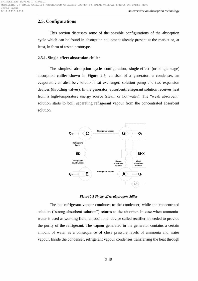
An overview on absorption technology
2-15
2.5. Configurations
This section discusses some of the possible configurations of the absorption
cycle which can be found in absorption equipment already present at the market or, at
least, in form of tested prototype.
2.5.1. Single-effect absorption chiller
The simplest absorption cycle configuration, single-effect (or single-stage)
absorption chiller shown in Figure 2.5, consists of a generator, a condenser, an
evaporator, an absorber, solution heat exchanger, solution pump and two expansion
devices (throttling valves). In the generator, absorbent/refrigerant solution receives heat
from a high-temperature energy source (steam or hot water). The ―weak absorbent‖
solution starts to boil, separating refrigerant vapour from the concentrated absorbent
solution.
Figure 2.5 Single-effect absorption chiller
The hot refrigerant vapour continues to the condenser, while the concentrated
solution (―strong absorbent solution‖) returns to the absorber. In case when ammonia-
water is used as working fluid, an additional device called rectifier is needed to provide
the purity of the refrigerant. The vapour generated in the generator contains a certain
amount of water as a consequence of close pressure levels of ammonia and water
vapour. Inside the condenser, refrigerant vapour condenses transferring the heat through
QC
Refrigerant vapour
Refrigerant
liquid
Strong
absorbent
solution
Weak
absorbent
solution
ED SHX
P
QG
Refrigerant vapour
E AQE QA
C G
Refrigerant
liquid+vapour
UNIVERSITAT ROVIRA I VIRGILI MODELLING OF SMALL CAPACITY ABSORPTION CHILLERS DRIVEN BY SOLAR THERMAL ENERGY OR WASTE HEAT Jerko Labus DL:T.1716-2011
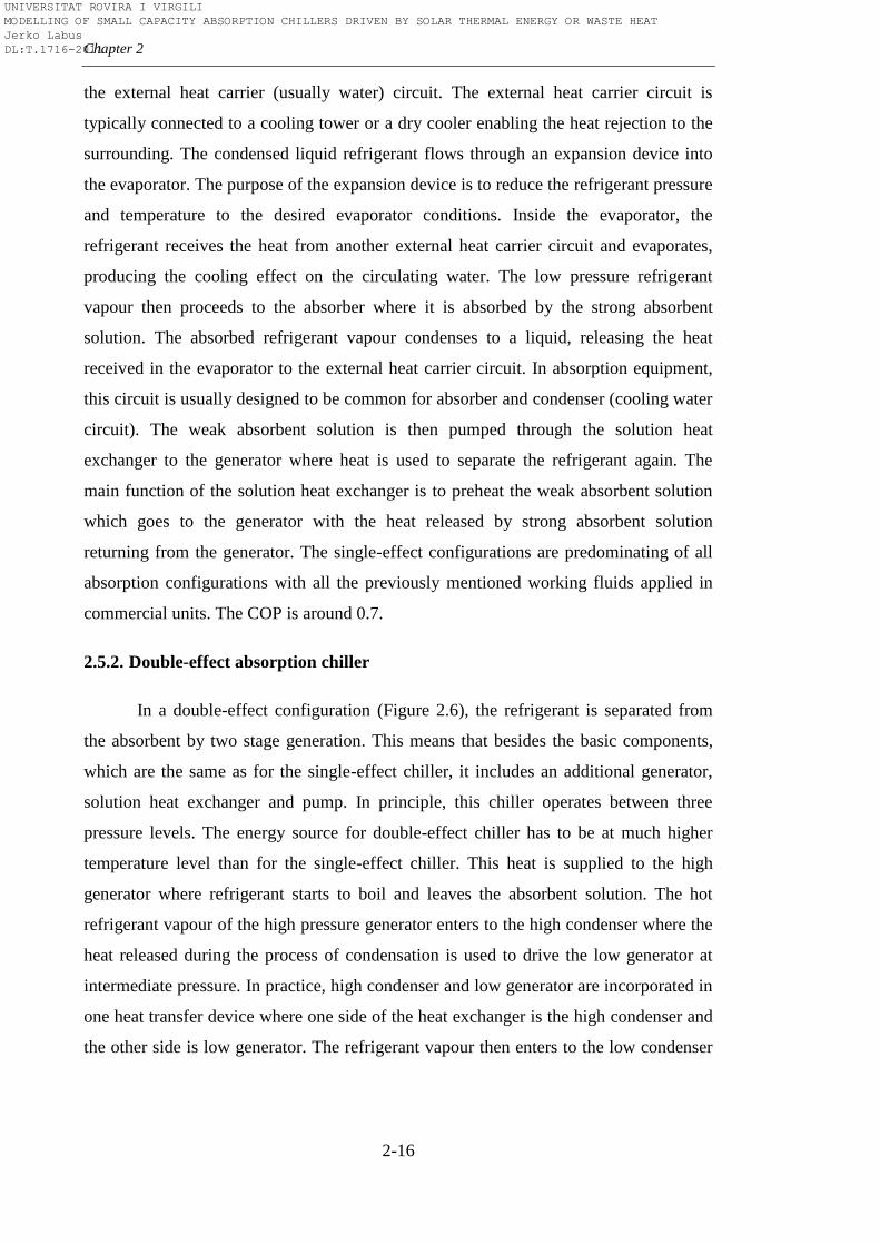
Chapter 2
2-16
the external heat carrier (usually water) circuit. The external heat carrier circuit is
typically connected to a cooling tower or a dry cooler enabling the heat rejection to the
surrounding. The condensed liquid refrigerant flows through an expansion device into
the evaporator. The purpose of the expansion device is to reduce the refrigerant pressure
and temperature to the desired evaporator conditions. Inside the evaporator, the
refrigerant receives the heat from another external heat carrier circuit and evaporates,
producing the cooling effect on the circulating water. The low pressure refrigerant
vapour then proceeds to the absorber where it is absorbed by the strong absorbent
solution. The absorbed refrigerant vapour condenses to a liquid, releasing the heat
received in the evaporator to the external heat carrier circuit. In absorption equipment,
this circuit is usually designed to be common for absorber and condenser (cooling water
circuit). The weak absorbent solution is then pumped through the solution heat
exchanger to the generator where heat is used to separate the refrigerant again. The
main function of the solution heat exchanger is to preheat the weak absorbent solution
which goes to the generator with the heat released by strong absorbent solution
returning from the generator. The single-effect configurations are predominating of all
absorption configurations with all the previously mentioned working fluids applied in
commercial units. The COP is around 0.7.
2.5.2. Double-effect absorption chiller
In a double-effect configuration (Figure 2.6), the refrigerant is separated from
the absorbent by two stage generation. This means that besides the basic components,
which are the same as for the single-effect chiller, it includes an additional generator,
solution heat exchanger and pump. In principle, this chiller operates between three
pressure levels. The energy source for double-effect chiller has to be at much higher
temperature level than for the single-effect chiller. This heat is supplied to the high
generator where refrigerant starts to boil and leaves the absorbent solution. The hot
refrigerant vapour of the high pressure generator enters to the high condenser where the
heat released during the process of condensation is used to drive the low generator at
intermediate pressure. In practice, high condenser and low generator are incorporated in
one heat transfer device where one side of the heat exchanger is the high condenser and
the other side is low generator. The refrigerant vapour then enters to the low condenser
UNIVERSITAT ROVIRA I VIRGILI MODELLING OF SMALL CAPACITY ABSORPTION CHILLERS DRIVEN BY SOLAR THERMAL ENERGY OR WASTE HEAT Jerko Labus DL:T.1716-2011
An overview on absorption technology
2-17
together with the liquid refrigerant condensed inside the tubes of the low generator. The
refrigerant is then throttled before entering into the evaporator where the cooling effect
is produced in the same way as in the case of single-effect chiller. All double-effect
chillers consist of same components. However, there are three variations regarding the
way in which the solution is circulated: parallel, series and reverse-series flow cycle. In
the parallel flow shown in Figure 2.6a, the weak absorbent solution is divided between
the low and the high generator. Within each of the generators, the weak absorbent
solution is concentrated before returning to absorber section. Figure 2.6b shows the
serial flow where the weak absorbent solution is pumped directly to the high generator
and concentrated to an intermediate solution concentration. The resulting intermediate
solution then flows to the low generator where is further concentrated before returning
to absorber. Finally, in the reverse-series flow (Figure 2.6c), the weak absorbent
solution is partially concentrated in low generator and then completely in the high
generator. The concentrated solution returns directly to absorber, avoiding the low
generator. These differences between the variations are mainly due to the preferences of
absorption equipment manufacturers. The main benefit of the double-effect absorption
chiller is higher efficiency obtained by using the input heat a second time. The COP is
around 1.2 and only H2O-LiBr commercial units are available (ammonia-water requires
much higher pressures).
Figure 2.6 Double-effect absorption chiller
ED SHX
ED SHX
HC
QC LC
EQE
P
P
A QA
QGHG
LG
ED SHX
ED SHX
HC
QC LC
EQE
P
A QA
QGHG
LG
ED SHX
ED SHX
HC
QC LC
EQE
P
P
A QA
QGHG
LG
a) b) c)
UNIVERSITAT ROVIRA I VIRGILI MODELLING OF SMALL CAPACITY ABSORPTION CHILLERS DRIVEN BY SOLAR THERMAL ENERGY OR WASTE HEAT Jerko Labus DL:T.1716-2011
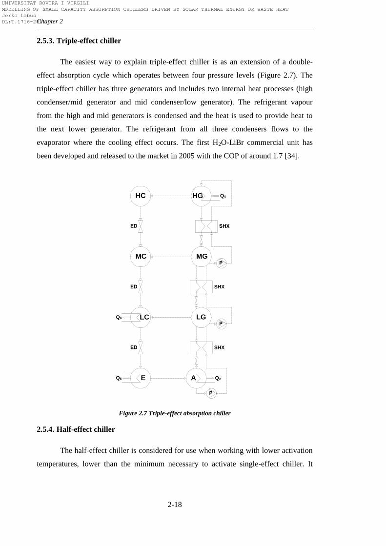
Chapter 2
2-18
2.5.3. Triple-effect chiller
The easiest way to explain triple-effect chiller is as an extension of a double-
effect absorption cycle which operates between four pressure levels (Figure 2.7). The
triple-effect chiller has three generators and includes two internal heat processes (high
condenser/mid generator and mid condenser/low generator). The refrigerant vapour
from the high and mid generators is condensed and the heat is used to provide heat to
the next lower generator. The refrigerant from all three condensers flows to the
evaporator where the cooling effect occurs. The first H2O-LiBr commercial unit has
been developed and released to the market in 2005 with the COP of around 1.7 [34].
Figure 2.7 Triple-effect absorption chiller
2.5.4. Half-effect chiller
The half-effect chiller is considered for use when working with lower activation
temperatures, lower than the minimum necessary to activate single-effect chiller. It
ED SHX
ED SHX
HC
QC LC
EQE
P
P
A QA
QGHG
LG
ED SHX
MG
P
MC
UNIVERSITAT ROVIRA I VIRGILI MODELLING OF SMALL CAPACITY ABSORPTION CHILLERS DRIVEN BY SOLAR THERMAL ENERGY OR WASTE HEAT Jerko Labus DL:T.1716-2011
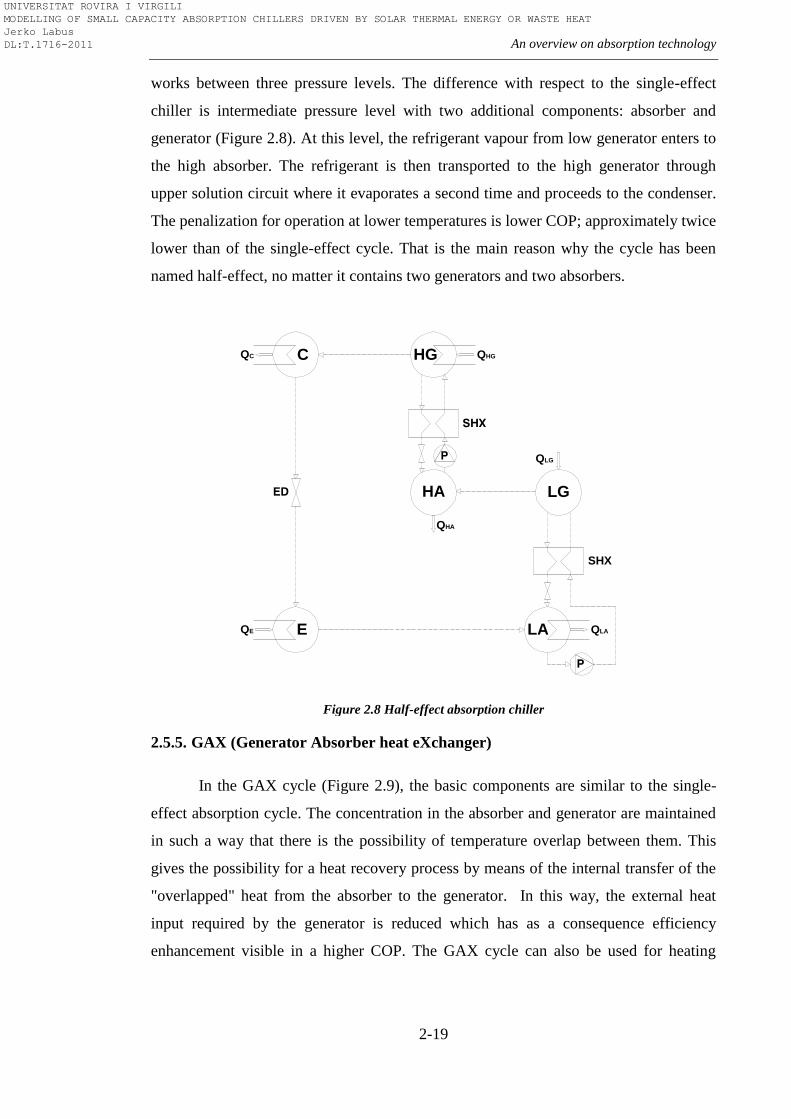
An overview on absorption technology
2-19
works between three pressure levels. The difference with respect to the single-effect
chiller is intermediate pressure level with two additional components: absorber and
generator (Figure 2.8). At this level, the refrigerant vapour from low generator enters to
the high absorber. The refrigerant is then transported to the high generator through
upper solution circuit where it evaporates a second time and proceeds to the condenser.
The penalization for operation at lower temperatures is lower COP; approximately twice
lower than of the single-effect cycle. That is the main reason why the cycle has been
named half-effect, no matter it contains two generators and two absorbers.
Figure 2.8 Half-effect absorption chiller
2.5.5. GAX (Generator Absorber heat eXchanger)
In the GAX cycle (Figure 2.9), the basic components are similar to the single-
effect absorption cycle. The concentration in the absorber and generator are maintained
in such a way that there is the possibility of temperature overlap between them. This
gives the possibility for a heat recovery process by means of the internal transfer of the
"overlapped" heat from the absorber to the generator. In this way, the external heat
input required by the generator is reduced which has as a consequence efficiency
enhancement visible in a higher COP. The GAX cycle can also be used for heating
SHX
SHX
EQE
P
LA QLA
QHGHG
LGHA
P QLG
QHA
QC C
ED
UNIVERSITAT ROVIRA I VIRGILI MODELLING OF SMALL CAPACITY ABSORPTION CHILLERS DRIVEN BY SOLAR THERMAL ENERGY OR WASTE HEAT Jerko Labus DL:T.1716-2011
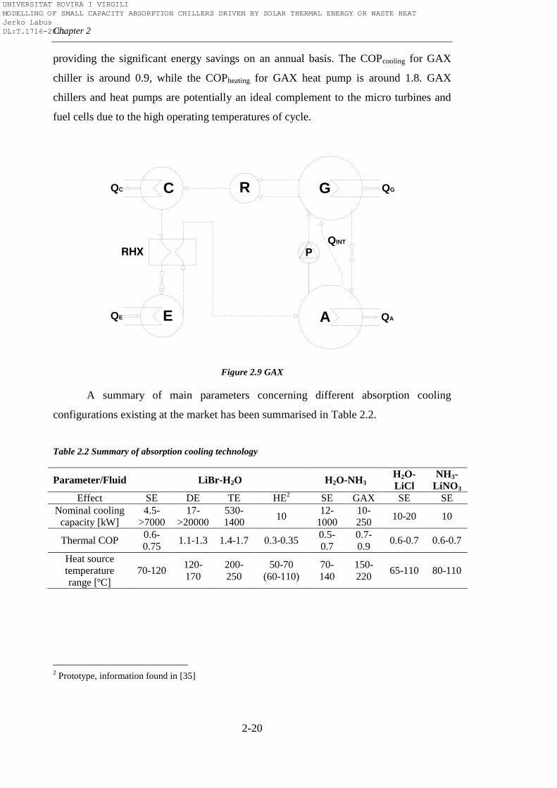
Chapter 2
2-20
providing the significant energy savings on an annual basis. The COPcooling for GAX
chiller is around 0.9, while the COPheating for GAX heat pump is around 1.8. GAX
chillers and heat pumps are potentially an ideal complement to the micro turbines and
fuel cells due to the high operating temperatures of cycle.
Figure 2.9 GAX
A summary of main parameters concerning different absorption cooling
configurations existing at the market has been summarised in Table 2.2.
Table 2.2 Summary of absorption cooling technology
Parameter/Fluid LiBr-H2O H2O-NH3 H2O-
LiCl
NH3-
LiNO3
Effect SE DE TE HE2 SE GAX SE SE
Nominal cooling
capacity [kW]
4.5-
>7000
17-
>20000
530-
1400 10
12-
1000
10-
250 10-20 10
Thermal COP 0.6-
0.75 1.1-1.3 1.4-1.7 0.3-0.35
0.5-
0.7
0.7-
0.9 0.6-0.7 0.6-0.7
Heat source
temperature
range [ºC]
70-120 120-
170
200-
250
50-70
(60-110)
70-
140
150-
220 65-110 80-110
2 Prototype, information found in [35]
QC
EQE
C R
P
G QG
A
RHX
QA
QINT
UNIVERSITAT ROVIRA I VIRGILI MODELLING OF SMALL CAPACITY ABSORPTION CHILLERS DRIVEN BY SOLAR THERMAL ENERGY OR WASTE HEAT Jerko Labus DL:T.1716-2011
An overview on absorption technology
2-21
2.5.6. Heat pump
As explained at the beginning of this Chapter, the distinction between a chiller
and a heat pump is only a function of the application, i.e. which temperature level will
be used. In the case of the absorption heat pump, this means that the driving heat at the
highest temperature level is used to produce heating at intermediate temperature level.
Since heat distribution units (fan-coils, radiators, etc) require higher temperature for
building heating and DHW applications, the operating temperatures of the cooling water
from absorber and condenser have to be at higher level (40-60ºC) than in case when it
operates as chiller. Also, this further affects the evaporator to operate at higher
temperatures as a direct consequence of the dependence between the three temperature
levels within the absorption cycle [35].
2.5.7. Chiller/heater
Chiller/heaters are in principle direct fired chillers which can be used to provide
both cooling and heating. This can be done in two ways. First way is to add an auxiliary
heating bundle allowing the chiller to produce both hot and chilled water. The auxiliary
heating bundle withdraws a portion of refrigerant vapour from the high generator to heat
the water to a temperature suitable for domestic hot water or heating. Second way is to
use evaporator as a condenser in the heating mode. This can be achieved by switching
the changeover valve for cooling/heating. The advantage of the first design is that it can
be used to operate in cooling only, heating only or simultaneous cooling and heating
modes while the second design permits only cooling or heating mode (no simultaneous
operation is possible). The chiller/heaters, therefore, can be installed in systems to
supplement, or even replace, primary heating or domestic hot water equipment.
2.6. Applications and trends
Synergy of absorption technology with other technologies can be performed by
using various applications. However, synergy with absorption does not guarantee that
these applications will be efficient and able to compete with other technologies, in
particular with conventional compression technology. The absorption becomes
attractive in specific applications when there are possibilities to use waste heat or
UNIVERSITAT ROVIRA I VIRGILI MODELLING OF SMALL CAPACITY ABSORPTION CHILLERS DRIVEN BY SOLAR THERMAL ENERGY OR WASTE HEAT Jerko Labus DL:T.1716-2011
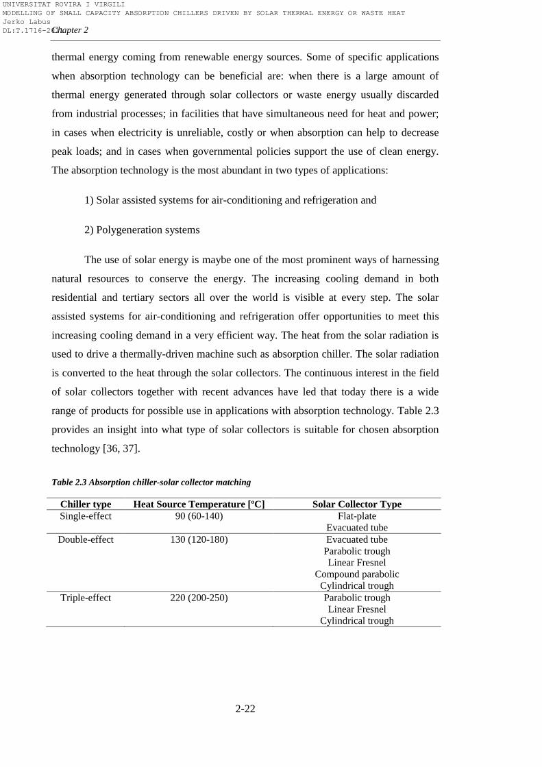
Chapter 2
2-22
thermal energy coming from renewable energy sources. Some of specific applications
when absorption technology can be beneficial are: when there is a large amount of
thermal energy generated through solar collectors or waste energy usually discarded
from industrial processes; in facilities that have simultaneous need for heat and power;
in cases when electricity is unreliable, costly or when absorption can help to decrease
peak loads; and in cases when governmental policies support the use of clean energy.
The absorption technology is the most abundant in two types of applications:
1) Solar assisted systems for air-conditioning and refrigeration and
2) Polygeneration systems
The use of solar energy is maybe one of the most prominent ways of harnessing
natural resources to conserve the energy. The increasing cooling demand in both
residential and tertiary sectors all over the world is visible at every step. The solar
assisted systems for air-conditioning and refrigeration offer opportunities to meet this
increasing cooling demand in a very efficient way. The heat from the solar radiation is
used to drive a thermally-driven machine such as absorption chiller. The solar radiation
is converted to the heat through the solar collectors. The continuous interest in the field
of solar collectors together with recent advances have led that today there is a wide
range of products for possible use in applications with absorption technology. Table 2.3
provides an insight into what type of solar collectors is suitable for chosen absorption
technology [36, 37].
Table 2.3 Absorption chiller-solar collector matching
Chiller type Heat Source Temperature [ºC] Solar Collector Type
Single-effect 90 (60-140) Flat-plate
Evacuated tube
Double-effect 130 (120-180) Evacuated tube
Parabolic trough
Linear Fresnel
Compound parabolic
Cylindrical trough
Triple-effect 220 (200-250) Parabolic trough
Linear Fresnel
Cylindrical trough
UNIVERSITAT ROVIRA I VIRGILI MODELLING OF SMALL CAPACITY ABSORPTION CHILLERS DRIVEN BY SOLAR THERMAL ENERGY OR WASTE HEAT Jerko Labus DL:T.1716-2011
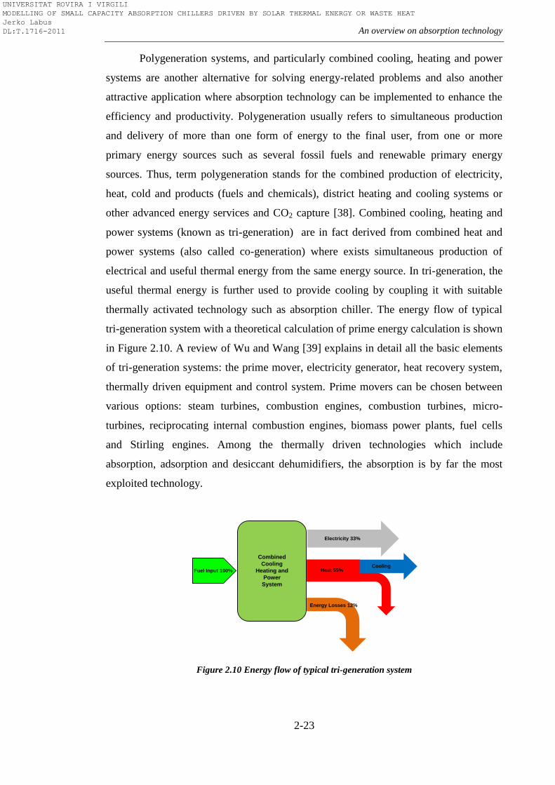
An overview on absorption technology
2-23
Polygeneration systems, and particularly combined cooling, heating and power
systems are another alternative for solving energy-related problems and also another
attractive application where absorption technology can be implemented to enhance the
efficiency and productivity. Polygeneration usually refers to simultaneous production
and delivery of more than one form of energy to the final user, from one or more
primary energy sources such as several fossil fuels and renewable primary energy
sources. Thus, term polygeneration stands for the combined production of electricity,
heat, cold and products (fuels and chemicals), district heating and cooling systems or
other advanced energy services and CO2 capture [38]. Combined cooling, heating and
power systems (known as tri-generation) are in fact derived from combined heat and
power systems (also called co-generation) where exists simultaneous production of
electrical and useful thermal energy from the same energy source. In tri-generation, the
useful thermal energy is further used to provide cooling by coupling it with suitable
thermally activated technology such as absorption chiller. The energy flow of typical
tri-generation system with a theoretical calculation of prime energy calculation is shown
in Figure 2.10. A review of Wu and Wang [39] explains in detail all the basic elements
of tri-generation systems: the prime mover, electricity generator, heat recovery system,
thermally driven equipment and control system. Prime movers can be chosen between
various options: steam turbines, combustion engines, combustion turbines, micro-
turbines, reciprocating internal combustion engines, biomass power plants, fuel cells
and Stirling engines. Among the thermally driven technologies which include
absorption, adsorption and desiccant dehumidifiers, the absorption is by far the most
exploited technology.
Figure 2.10 Energy flow of typical tri-generation system
Fuel Input 100%
Electricity 33%
Heat 55%
Energy Losses 12%
Cooling
Combined
Cooling
Heating and
Power
System
UNIVERSITAT ROVIRA I VIRGILI MODELLING OF SMALL CAPACITY ABSORPTION CHILLERS DRIVEN BY SOLAR THERMAL ENERGY OR WASTE HEAT Jerko Labus DL:T.1716-2011
Chapter 2
2-24
Within the polygeneration systems, solar assisted and cogeneration technologies
are in many cases complementary technologies combined with absorption machines.
Industrial processes with waste heat are another application where absorption machines
can be implemented efficiently both for cooling and heating. Absorption equipment has
also found its place in district cooling and heating networks where it can be
implemented in various ways. To avoid confusion, district cooling and heating networks
can be considered as a part of poly-generation since they normally serve for energy
distribution, but also can be observed as an individual concept which can be coupled
with absorption technology. Very interesting conceptual solutions with absorption
machines such as plant processing heating and boiler water heating, district heating by
utilizing waste heat recovered from industrial processes or by utilizing hot underground
water, utilizing well water for greenhouse floriculture or for fish farm are suggested in
[40]. Absorption technology can also be used for desalination as reported in one of the
studies of Alarcón-Padilla et al. [41] on solar thermal desalination system in Almeria,
Spain. The existing desalination system based on multi-effect desalination was
connected to a double-effect absorption heat pump. The results of the study showed that
50% reduction of the required solar field area can be achieved in this way compared to
solar multi-effect desalination. Hybrid systems with coupled compression-absorption
refrigeration cycles are also among the actual applications. Hwang [42] presented the
integrated refrigeration system with micro turbine and absorption chiller. The
absorption chiller was used to subcool the refrigerant in a vapour compression system,
enhancing the efficiency of the cycle and consequently reducing the required size of the
micro turbine. Another example are hybrid refrigeration systems for mobile applications
as one presented in the paper of Monsberger et al. [43] where the solid oxide fuel cell
was used to power compression-absorption cycle for transport refrigeration. As it can be
seen from the examples described above, the absorption technology is not only
attractive for refrigeration, air-conditioning and freezing, but also can meet the demand
for energy conservation and protection. There are many other applications, which are
not described above, because they are still in development or not mature yet. Actually, a
great number of the absorption applications are in the stage of demonstration and
prototyping. With respect to the trends in absorption machines, research and
development of new working fluids is inexhaustible subject of interest. The advantages
UNIVERSITAT ROVIRA I VIRGILI MODELLING OF SMALL CAPACITY ABSORPTION CHILLERS DRIVEN BY SOLAR THERMAL ENERGY OR WASTE HEAT Jerko Labus DL:T.1716-2011
An overview on absorption technology
2-25
of promising binary, ternary and quaternary salt mixtures are depicted and discussed
thoroughly in Section 2.4 on working fluids. Lower efficiency and cost of absorption
machine are still the flaming issue. That is the reason why a lot of research work is
focused on enhancing the heat and mass transfer in order to improve the performance.
As indicated in [28] the improved efficiency depends on inexpensive, compact
components (compact heat exchangers primarily). Jeong and Garimela [44] used three-
flow-regime model to evaluate the influence of the tube diameters in falling-film
absorbers. The results showed that cooling capacity can increase significantly as the
tube diameter decrease. On the other hand, tube surface wettability decreases which can
be a limiting factor to miniaturization. The advanced micro heat exchangers are also the
trend of development as shown in the study of the feasibility to apply the micro
absorption heat pump in protective clothing [45]. A various micro electromechanical
components are reviewed in this study. The effect of nanoparticles was investigated in
the study of Lee et al. [46], where it was confirmed that nanoparticles can enhance heat
transfer and help in design of highly effective compact absorber for NH3-H2O
absorption system. Ali [47] demonstrated that the use of membranes can be
advantageous when designing compact plates-and-frames absorber due to higher
specific mass transfer area to the absorber volume. The developments in solar energy
collecting and transferring technology have produced the positive impact on absorption
technology. Thus, the use of parabolic trough collectors and linear Fresnel collectors
which can produce water at medium temperatures have opened the interest in the fields
of power and cooling cycles [48] and multi-effect absorption equipment [49, 50]. In
order to achieve higher efficiency, the hybrid and GAX cycles become very interesting,
especially in the USA. The focus is more on system integration. How to integrate
absorption machines in complex, polygeneration systems in the most efficient way. This
further implies the interest in optimization and control strategies of the absorption
machine and whole system. The paper of Ziegler [51] points out the importance of
appropriate control strategies for whole absorption system with external pumps and fans
in order to reduce their parasitic power consumption and increase overall efficiency of
the system. Thermal storage for the (ab)sorption machine is another important issue
since lots of objects in residential and tertiary sector needs cooling during the night.
Phase Change Materials (PCM) and ice-storage are some of the interesting solutions
UNIVERSITAT ROVIRA I VIRGILI MODELLING OF SMALL CAPACITY ABSORPTION CHILLERS DRIVEN BY SOLAR THERMAL ENERGY OR WASTE HEAT Jerko Labus DL:T.1716-2011

Chapter 2
2-26
[52]. Historical trend in absorption research, presented in [28], shows increased number
of papers from 1996 till 2010 in all areas, with especially rising interest for absorption
heat transformers. Finally, a lot of effort has been made lately in commercialization of a
small scale absorption equipment and their integration with solar and micro-
cogeneration systems for residential (single-family and multi-family) and light-
commercial applications [12, 53, 54]. In the development of small scale absorption
equipment a special attention has been given to the development of air-cooled chillers.
Having in mind that the main objective of this thesis is the methodology for small scale
absorption chillers, the following paragraphs will try to highlight all the relevant
achievements together with the current situation in the field of small scale absorption
chillers.
2.7. Small capacity absorption machines - state of the art
The development of small capacity absorption machines has been mostly
connected to the research in the field of solar powered systems for air-conditioning. The
milestone was the moment when the International Energy Agency (IEA) started Task 25
―Solar Assisted Air Conditioning of Buildings‖. Under this task, thermally driven
chillers (mainly absorption chillers) have been identified as a very promising
technology for solar assisted air conditioning in order to meet the increased demand for
cooling in the residential sector. As one of the main objectives, the IEA has set the
intensive R&D in the field of small scale thermally driven chillers and preparation for
market entry of these chillers. IEA Task 38 ―Solar Air-Conditioning and Refrigeration‖
and Annex 34 ―Thermally Driven Heat Pumps for Heating and Cooling‖ has continued
the same trend. Several European projects such as SOLHEATCOOL, ASODECO,
SACE, NEGST, ROCOCO, SAHC, CAMELIA, SolarCombi+, etc have promoted and
supported the development of the small scale absorption chillers as a part of the IEA
SHC initiative. Another important factor which has contributed to the development of
small scale absorption machines are micro CHP systems which has been identified as
one of the possible solutions to reduce energy consumption and CO2 emission by 20%
until 2020. These small systems can help the operation of the local electricity
distribution grid as well as to provide heating and hot water for small commercial
buildings, apartments and individual houses. The heat from micro CHP systems can be
UNIVERSITAT ROVIRA I VIRGILI MODELLING OF SMALL CAPACITY ABSORPTION CHILLERS DRIVEN BY SOLAR THERMAL ENERGY OR WASTE HEAT Jerko Labus DL:T.1716-2011
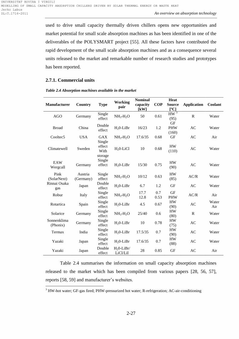
An overview on absorption technology
2-27
used to drive small capacity thermally driven chillers opens new opportunities and
market potential for small scale absorption machines as has been identified in one of the
deliverables of the POLYSMART project [55]. All these factors have contributed the
rapid development of the small scale absorption machines and as a consequence several
units released to the market and remarkable number of research studies and prototypes
has been reported.
2.7.1. Commercial units
Table 2.4 Absorption machines available in the market
Manufacturer Country Type Working
pair
Nominal
capacity
[kW]
COP
Heat
Source
[ºC]
Application Coolant
AGO Germany Single
effect NH3-H2O 50 0.61
HW 3
(95) R Water
Broad China Double
effect H20-LiBr 16/23 1.2
GF
PHW
(160)
AC Water
Cooltec5 USA GAX NH3-H2O 17.6/35 0.68 GF AC Air
Climatewell Sweden
Single
effect
With
storage
H20-LiCl 10 0.68 HW
(110) AC Water
EAW
Wergcall Germany
Single
effect
H20-LiBr 15/30 0.75 HW
(90) AC Water
Pink
(SolarNext)
Austria
(Germany)
Single
effect NH3-H2O 10/12 0.63
HW
(85) AC/R Water
Rinnai Osaka
gas Japan
Double
effect H20-LiBr 6.7 1.2 GF AC Water
Robur Italy Single
effect NH3-H2O
17.7
12.8
0.7
0.53
GF
PHW AC/R Air
Rotartica Spain Single
effect H20-LiBr 4.5 0.67
HW
(90) AC
Water
Air
Solarice Germany Single
effect NH3-H2O 25/40 0.6
HW
(80) R Water
Sonnenklima
(Phonix) Germany
Single
effect H20-LiBr 10 0.78
HW
(75) AC Water
Termax India Single
effect H20-LiBr 17.5/35 0.7
HW
(90) AC Water
Yazaki Japan Single
effect H20-LiBr 17.6/35 0.7
HW
(88) AC Water
Yazaki Japan Double
effect
H20-LiBr/
LiCl/LiI 28 0.85 GF AC Air
Table 2.4 summarises the information on small capacity absorption machines
released to the market which has been compiled from various papers [28, 56, 57],
reports [58, 59] and manufacturer’s websites.
3 HW-hot water; GF-gas fired; PHW-pressurized hot water; R-refrigeration; AC-air-conditioning
UNIVERSITAT ROVIRA I VIRGILI MODELLING OF SMALL CAPACITY ABSORPTION CHILLERS DRIVEN BY SOLAR THERMAL ENERGY OR WASTE HEAT Jerko Labus DL:T.1716-2011
Chapter 2
2-28
2.7.2. Research and development, prototypes
Despite the increased interest in the last two decades and a number of
commercialized units, the development of small capacity absorption machines has
started much earlier. This fact is supported by a large number of scientific papers,
research efforts and numerous prototypes developed worldwide. An overview of the
scientific achievements is given to complete the image of the possibilities which small
absorption machines can offer, but also to point out the deficiencies of the technology.
With emphasis on use of renewable energy sources, this review covers all the relevant
applications, disclosures and prototypes connected to the small absorption machines.
In a period from 1975-1984, the Carrier Corporation made lots of efforts on
research and development of solar powered absorption chillers which can dissipate
directly to air [58, 60]. As a result of this research, a prototype of air-cooled, single-
effect absorption chiller with cooling capacity of around 35kW was developed. Sun
powered with H2O-LiBr working pair, the prototype could achieve a COP of 0.71.
Unfortunately, this prototype has never entered into serial production. The double-
effect air-cooled absorption machine with a compact body and suitably small
installation area is described in the patent of Kurosawa et al. [61]. The disclosure was
based on the 15kW prototype which used H2O-LiBr working pair. The COP of this
double-effect absorption chiller was 0.93. Gas Research Institute from Chicago was also
involved in research with small capacity air-cooled machines. The result of the research
was direct-fired double-effect absorption machine [62]. A 10kW prototype used H2O-
LiBr working pair and could operate both as chiller and as a heat pump. This air-cooled
absorption machine had a COP around 0.95 in cooling mode and was intended for small
residential applications. One of the interesting issues connected to this prototype was
the automatic decrystallization technique. The second interesting issue was modular
type of plate heat exchangers for the evaporator and absorber [63]. This disclosure
enables direct heat exchange with the cold air (evaporator) and cooling air (absorber).
The Yazaki Company was also working on development of small air-cooled absorption
chiller/heater [64]. The reported COP of the 4.5kW double-effect absorption chiller
prototype was 0.8 and it was working with their newly developed LiBr-LiCl-LiI
solution [65]. This solution, also called Carroll mixture offers a safer operation of the
UNIVERSITAT ROVIRA I VIRGILI MODELLING OF SMALL CAPACITY ABSORPTION CHILLERS DRIVEN BY SOLAR THERMAL ENERGY OR WASTE HEAT Jerko Labus DL:T.1716-2011
An overview on absorption technology
2-29
absorption chiller due to sufficiently low crystallization temperature. Another
absorption product from Yazaki can be found in the experimental study of Li and
Sumathy [66] on solar air-conditioning system with storage tank. The absorption chiller
used in system is Yazaki WFC-400S with nominal capacity of 4.7kW. The chiller has a
generator inlet temperature range of 75-100ºC and a cooling water temperature range of
24-31ºC. It is based on single-effect cycle which uses H2O-LiBr working pair, but with
one difference. This chiller belongs to the group of the self-circulate absorption
refrigeration systems or, more precisely, to the systems which use hot-air-bubble pump
principle. The difference of these systems with respect to the classical absorption
system is that they do not require any electricity to drive a circulation pump. With water
as a refrigerant, the difference between pressure levels of the condenser and the
evaporator becomes very low and can be maintained by using the principle of
hydrostatic-head. The bubble pump circulates the solution strong in refrigerant from the
absorber to the generator while the gravitation force enables the return of the solution
weak in refrigerant back to the absorber. Also, it is worth to mention that Yazaki is one
of the first who started the mass production of small capacity absorption chillers for air-
conditioning applications. In 1970, Yazaki launched first ―Aroace‖ absorption
chiller/heater series with CH-1000 (12.25kW capacity) and CH-1500 (17.5kW) models.
In 1978, the company started with production of models WFC-400 and WFC-600 (7
kW), water fired chillers which use bubble pump principle [67]. These models are not
any more available at the market. At the Gazi University in Turkey, Sozen et al. [68]
developed a prototype of an NH3-H2O absorption heat pump. This absorption system
was designed to operate with a parabolic solar collector, having an optimum
performance at generator inlet temperature of 90ºC. Typical COP values for cooling
mode were in the range of 0.58-0.8 and in the range of 1.5-1.8 for heating mode. Due to
the minimum evaporator temperature of 3ºC, the authors recommended the use of the
system both for food preservation and for air-conditioning. Also, authors recommended
the modification of the evaporator and absorber in order to decrease high exergy loss of
the heat pump. Ben Ezzine et al. [69] considered the possibility of solar cooling with
double-effect ammonia-water absorption cycle. A thermodynamic analysis based on the
Second Law indicate that absorber, solution heat exchanger and condenser have the
greatest potential to improve the chiller’s efficiency which can be more viable for
UNIVERSITAT ROVIRA I VIRGILI MODELLING OF SMALL CAPACITY ABSORPTION CHILLERS DRIVEN BY SOLAR THERMAL ENERGY OR WASTE HEAT Jerko Labus DL:T.1716-2011
Chapter 2
2-30
residential and small commercial applications. The main obstacle for development and
commercialization of double-effect ammonia-water chillers are the safety problems
which may be caused by higher operating pressures of ammonia. An experimental
prototype of 10kW single-effect H2O-LiBr absorption heat pump was developed and
evaluated by Argiriou et al. [70]. A 10kW prototype, suitable for residential and small
building applications, was connected to a cooling tower and driven by solar heat at low
driving temperatures through solar collectors. The maximum obtained COP was 0.74.
The comparison with a conventional cooling installation using a compression type heat
pump showed that this type of system could achieve 20-27% of energy savings. The
University of Applied Sciences in Stuttgart, Germany developed several prototypes of
solar heat driven ammonia-water diffusion absorption cooling machine for air-
conditioning applications [71]. A diffusion absorption cooling machine also belongs to
self-circulate absorption systems. Since now ammonia is the refrigerant, a bubble-pump
is not sufficient to overcome differential pressure between the condenser and the
evaporator. The solution is to charge an auxiliary gas to the evaporator and absorber in
order to keep the partial pressure of ammonia low enough to correspond with the
required temperatures inside the evaporator. In this way, the pressure difference of the
system is decreased which further enables the utilization of the bubble-pump. The
designed cooling capacity of the diffusion absorption cooling machine was 2.5kW and
Helium was used to keep the pressure equilibrium. The best results were obtained with
the third prototype when the initially chosen plate heat exchangers were replaced by
coaxial solution heat exchangers. In the operating range of the generator inlet
temperature from 100 to 150ºC, the experimental results of the prototype showed
cooling capacities from 0.7kW up to 3.0kW with maximum reached COP of 0.38.
Another ammonia-water absorption chiller prototype was also developed in Germany, at
the ITW Stuttgart [72]. The designed cooling capacity of this single-effect absorption
chiller is 10kW and it is powered directly with the hot water from the solar collectors,
without any thermal storage tank in between. The solution circulation to the required
high pressure level in this case is achieved by a membrane pump. According to the
experiments reported by Zetzsche et al. the cooling capacity was in the range of 5.4-
10.7kW and the COP in the range 0.58-0.74. Around the same time, the Technical
University Graz in Austria built another prototype of a ammonia-water absorption heat
UNIVERSITAT ROVIRA I VIRGILI MODELLING OF SMALL CAPACITY ABSORPTION CHILLERS DRIVEN BY SOLAR THERMAL ENERGY OR WASTE HEAT Jerko Labus DL:T.1716-2011
An overview on absorption technology
2-31
pump with 5kW cooling capacity [73]. The prototype was indirectly driven through a
heat medium circuit which can use any type of renewable energy. Although mainly
designed for solar air-conditioning, the operating temperature range of cold water (-10-
20ºC) makes it suitable for refrigeration as well. The reported COP for cooling mode
was in the range of 0.4-0.75. At the University Politecnica de Cataluña, Castro et al.
[74] developed and tested the prototype of an air-cooled absorption chiller of about 2
kW cooling capacity using H2O-LiBr working fluid. The prototype has a mechanical
solution pump, horizontal-tube falling film generator, an evaporator and the air-cooled
absorber and condenser consisted of vertical finned tube batteries. The maximum
obtained COP of the chiller was 0.65 with the electrical consumption of the fan of
approximately 250W. In a period from 2001 to 2002, the German Aerospace Centre
(DLR) developed the prototype of a double-effect H2O-LiBr absorption chiller driven
by parabolic solar collectors. For the generator inlet temperature range of 150-180ºC the
COP was in the range of 1.2-1.4. An air-cooled GAX prototype powered by natural gas
and solar energy was developed in Mexico, at the University Autonoma de Baja
California. The prototype with a cooling capacity of 10.6kW could achieve COP of 0.86
[75]. Kim and Infante Ferreira [76] were investigating the development of half-effect
parallel-flow absorption chiller for solar air-conditioning in hot weathers. Based on the
theoretical design, a prototype of an air-cooled H2O-LiBr absorption chiller with the
purpose to be combined with low-cost flat solar collectors was constructed at Delft
University of Technology, the Netherlands. After performing the experiments, during
which the heat rejection temperature was varied in the range of 30-50ºC and the
generator inlet temperature in the range of 67-108 ºC, the maximum reached COP was
0.35 [35]. Another market ready prototype of ammonia-water chiller was developed by
Austrian company SolarFrost [77]. Actually, it is diffusion absorption cooling machine
with cooling capacity of 2kW, and COP in the range of 0.6-0.7. A steam driven solution
pump was developed for that purpose. It is based on the principle that hot ammonia
solution has a high steam pressure while cold ammonia solution absorbs ammonia gas.
The company developed two versions, one with plate heat exchangers and the second
with tube heat exchangers. In Portugal, under the framework of the EU project
Polysmart, the institute INETI together with the company AoSol developed another
prototype of an air-cooled ammonia-water absorption chiller. This single-effect
UNIVERSITAT ROVIRA I VIRGILI MODELLING OF SMALL CAPACITY ABSORPTION CHILLERS DRIVEN BY SOLAR THERMAL ENERGY OR WASTE HEAT Jerko Labus DL:T.1716-2011
Chapter 2
2-32
absorption chiller had a cooling capacity between 5-6 kW and could achieve COP of
approximately 0.65. One of the most recent disclosures was the newly developed
ammonia-lithium nitrate mixture patented by Bourouis et al. [78]. Using the patented
solution, several single-effect prototypes were recently developed at Rovira i Virgili
University in Spain [33]. First developed prototype was water-cooled, with designed
cooling capacity of 10kW. Experimental results showed that for generator inlet
temperature and chilled water temperature of 90ºC and 15ºC, respectively, chiller can
produce 11.5kW of cooling. The maximum obtained COP was 0.69. The second
developed prototype was air-cooled, which could obtain slightly lower capacity of
9.1kW and COP of around 0.64.
The use of absorption technology in the low temperature applications like food
and medicament storage or ice-making is also possible. Small capacity absorption
machine with refrigeration purpose were subject of interest for many researchers. The
absorption technologies become very attractive for refrigeration purpose in remote or
rural areas where the electricity is unavailable. This fact is supported by numerous
research studies and developed prototypes.
In 1986, Uppal et al. [79] built a low cost, solar driven NH3-H2O absorption
refrigerator. The purpose of this small capacity (56 litres) refrigerator was vaccine
storage in the remote locations of Third World countries. Bansal et al. [80] designed and
constructed a prototype of a solar cooling unit based on solid-vapour intermittent
absorption system. The unit of 1.5 kWh/day cooling capacity used ammonia as a
refrigerant and IMPEX material (80% SrCl, and 20% Graphite) as absorbent. However,
the unit had a very poor performance with an overall COP less than 0.1 and also had the
problem with the corrosion. Erickson [81] used half-effect absorption cycle to develop
icemaker for isolated fishing villages in Alaska. This absorption refrigeration prototype
was powered by waste heat from Diesel engine at 75ºC with the obtained COP of 0.3.
An intermittent absorption refrigerator powered by solar pond and using NH3-H2O
solution was built by Sierra et al. [82]. The refrigerator had the COP in the range of
0.24-0.28 and the minimum operating evaporation temperature was -2ºC. Another
absorption refrigerator prototype with cooling capacity of 4.65kW was designed and
tested in Turkey by Dincer et al. [83]. The experimental COP at generator inlet
UNIVERSITAT ROVIRA I VIRGILI MODELLING OF SMALL CAPACITY ABSORPTION CHILLERS DRIVEN BY SOLAR THERMAL ENERGY OR WASTE HEAT Jerko Labus DL:T.1716-2011
An overview on absorption technology
2-33
temperature of 90ºC was around 0.45. One more example of absorption refrigeration for
vaccine storage was reported by Hammad and Habali [84]. They used solar-powered
absorption refrigeration cycle with NH3–H2O working pair to design a prototype which
would cool a vaccine cabinet in remote desert areas. The simulated COP was in the
range of 0.5-0.65. At the Politecnical University of Madrid, a group of researchers [85]
developed and tested a prototype of 2kW absorption refrigerator to operate with a
concentrating solar power system. The main purpose of this small NH3–H2O absorption
system was to meet refrigeration requirements in small rural operations. However, the
test results showed very poor performance of the prototype with the COP lower than
0.05. Pilatowsky et al. [86] investigated the use of absorption refrigeration systems
coupled with evacuated tube collectors for milk cooling in the rural regions of Mexico.
The results showed that the monomethylamine-water pair is satisfactory to obtain
evaporator temperature range of -5 to 10ºC at generation temperature range of 60-80ºC.
This further permits the use of high efficiency evacuated tube collectors to provide
required cooling energy for typical daily milk production in the rural regions of Mexico.
The obtained COP values varied from 0.15 to 0.7. In addition, the example of small
capacity absorption machine which operates as absorption heat transformer can be
found in the paper of Abrahamsson et al. [87]. The authors designed and tested a 10kW
absorption heat transformer unit based on self-circulation principle and using NaOH-
water working pair. Viewed from the perspective of the absorption components, very
interesting research studies were conducted by Bourouis et al. [88] and Lorton et al.
[89]. Bourouis et al. investigated the possibility of using multi component salt solutions
in the air-cooled absorbers. The conclusion was that these solutions have the advantage
over the conventional H2O-LiBr working pair due to the higher solubility at higher salt
concentrations and, in accordance with that fact, these solutions are very suitable for the
air-cooled absorbers. Lorton et al. presented the prototype of the double-effect
absorption machine based on rotational technology which intensifies heat and mass
transfer inside the components. For more information about recent developments in
absorption cooling and more exhaustive R&D analysis, the author recommends several
review papers [90-92].
UNIVERSITAT ROVIRA I VIRGILI MODELLING OF SMALL CAPACITY ABSORPTION CHILLERS DRIVEN BY SOLAR THERMAL ENERGY OR WASTE HEAT Jerko Labus DL:T.1716-2011
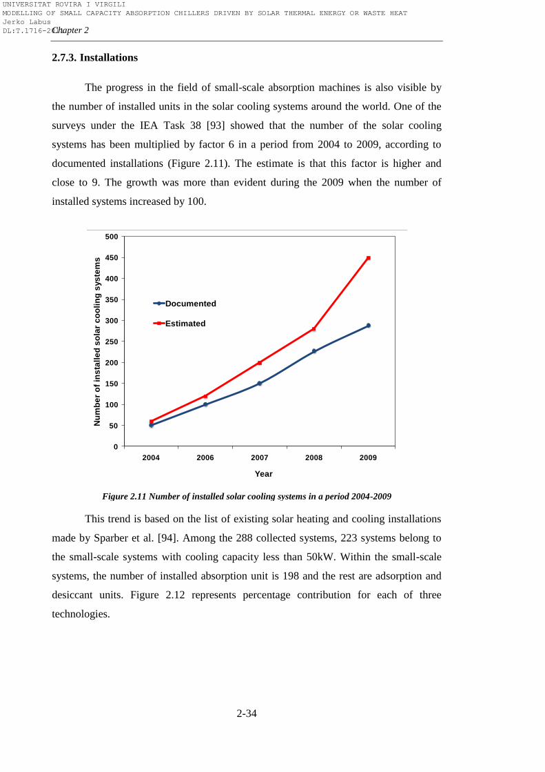
Chapter 2
2-34
2.7.3. Installations
The progress in the field of small-scale absorption machines is also visible by
the number of installed units in the solar cooling systems around the world. One of the
surveys under the IEA Task 38 [93] showed that the number of the solar cooling
systems has been multiplied by factor 6 in a period from 2004 to 2009, according to
documented installations (Figure 2.11). The estimate is that this factor is higher and
close to 9. The growth was more than evident during the 2009 when the number of
installed systems increased by 100.
Figure 2.11 Number of installed solar cooling systems in a period 2004-2009
This trend is based on the list of existing solar heating and cooling installations
made by Sparber et al. [94]. Among the 288 collected systems, 223 systems belong to
the small-scale systems with cooling capacity less than 50kW. Within the small-scale
systems, the number of installed absorption unit is 198 and the rest are adsorption and
desiccant units. Figure 2.12 represents percentage contribution for each of three
technologies.
0
50
100
150
200
250
300
350
400
450
500
2004 2006 2007 2008 2009
Nu
mb
er
of
ins
tall
ed
so
lar
co
oli
ng
sys
tem
s
Year
Documented
Estimated
UNIVERSITAT ROVIRA I VIRGILI MODELLING OF SMALL CAPACITY ABSORPTION CHILLERS DRIVEN BY SOLAR THERMAL ENERGY OR WASTE HEAT Jerko Labus DL:T.1716-2011
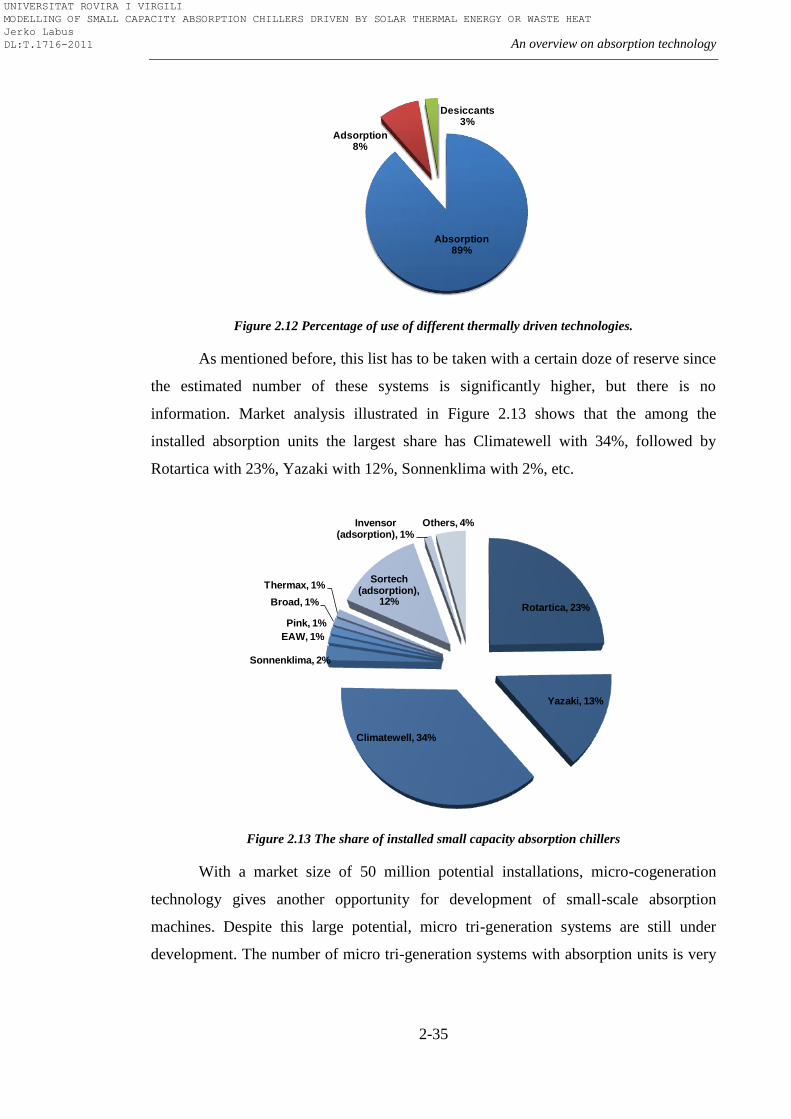
An overview on absorption technology
2-35
Figure 2.12 Percentage of use of different thermally driven technologies.
As mentioned before, this list has to be taken with a certain doze of reserve since
the estimated number of these systems is significantly higher, but there is no
information. Market analysis illustrated in Figure 2.13 shows that the among the
installed absorption units the largest share has Climatewell with 34%, followed by
Rotartica with 23%, Yazaki with 12%, Sonnenklima with 2%, etc.
Figure 2.13 The share of installed small capacity absorption chillers
With a market size of 50 million potential installations, micro-cogeneration
technology gives another opportunity for development of small-scale absorption
machines. Despite this large potential, micro tri-generation systems are still under
development. The number of micro tri-generation systems with absorption units is very
Absorption89%
Adsorption8%
Desiccants3%
Rotartica, 23%
Yazaki, 13%
Climatewell, 34%
Sonnenklima, 2%
EAW, 1%
Pink, 1%
Broad, 1%
Thermax, 1%Sortech
(adsorption), 12%
Invensor (adsorption), 1%
Others, 4%
UNIVERSITAT ROVIRA I VIRGILI MODELLING OF SMALL CAPACITY ABSORPTION CHILLERS DRIVEN BY SOLAR THERMAL ENERGY OR WASTE HEAT Jerko Labus DL:T.1716-2011
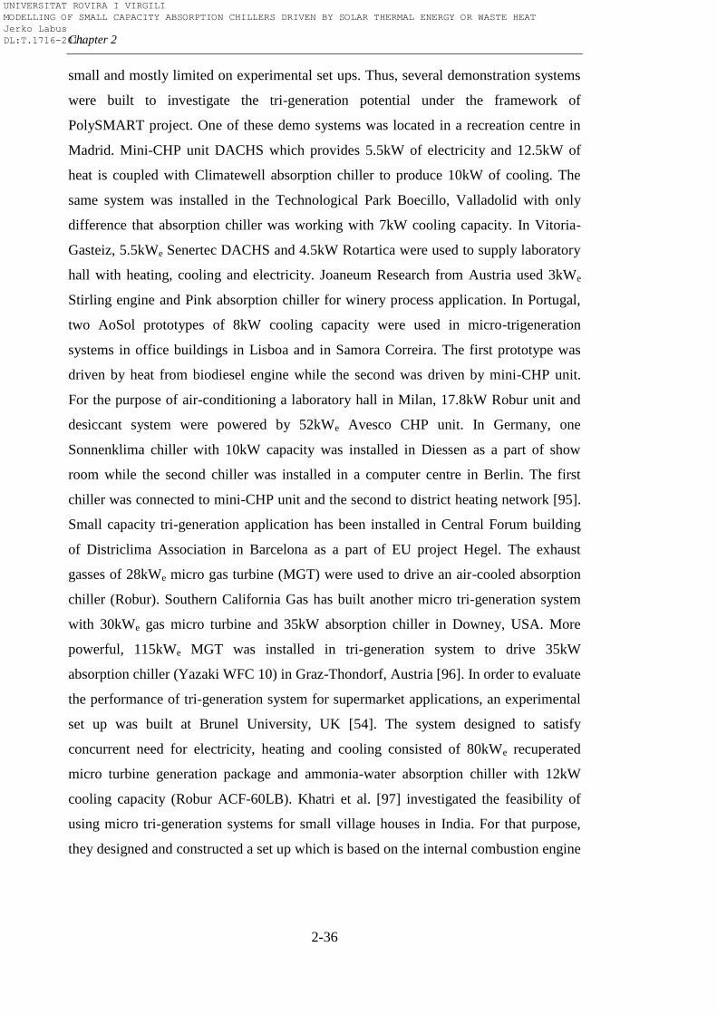
Chapter 2
2-36
small and mostly limited on experimental set ups. Thus, several demonstration systems
were built to investigate the tri-generation potential under the framework of
PolySMART project. One of these demo systems was located in a recreation centre in
Madrid. Mini-CHP unit DACHS which provides 5.5kW of electricity and 12.5kW of
heat is coupled with Climatewell absorption chiller to produce 10kW of cooling. The
same system was installed in the Technological Park Boecillo, Valladolid with only
difference that absorption chiller was working with 7kW cooling capacity. In Vitoria-
Gasteiz, 5.5kWe Senertec DACHS and 4.5kW Rotartica were used to supply laboratory
hall with heating, cooling and electricity. Joaneum Research from Austria used 3kWe
Stirling engine and Pink absorption chiller for winery process application. In Portugal,
two AoSol prototypes of 8kW cooling capacity were used in micro-trigeneration
systems in office buildings in Lisboa and in Samora Correira. The first prototype was
driven by heat from biodiesel engine while the second was driven by mini-CHP unit.
For the purpose of air-conditioning a laboratory hall in Milan, 17.8kW Robur unit and
desiccant system were powered by 52kWe Avesco CHP unit. In Germany, one
Sonnenklima chiller with 10kW capacity was installed in Diessen as a part of show
room while the second chiller was installed in a computer centre in Berlin. The first
chiller was connected to mini-CHP unit and the second to district heating network [95].
Small capacity tri-generation application has been installed in Central Forum building
of Districlima Association in Barcelona as a part of EU project Hegel. The exhaust
gasses of 28kWe micro gas turbine (MGT) were used to drive an air-cooled absorption
chiller (Robur). Southern California Gas has built another micro tri-generation system
with 30kWe gas micro turbine and 35kW absorption chiller in Downey, USA. More
powerful, 115kWe MGT was installed in tri-generation system to drive 35kW
absorption chiller (Yazaki WFC 10) in Graz-Thondorf, Austria [96]. In order to evaluate
the performance of tri-generation system for supermarket applications, an experimental
set up was built at Brunel University, UK [54]. The system designed to satisfy
concurrent need for electricity, heating and cooling consisted of 80kWe recuperated
micro turbine generation package and ammonia-water absorption chiller with 12kW
cooling capacity (Robur ACF-60LB). Khatri et al. [97] investigated the feasibility of
using micro tri-generation systems for small village houses in India. For that purpose,
they designed and constructed a set up which is based on the internal combustion engine
UNIVERSITAT ROVIRA I VIRGILI MODELLING OF SMALL CAPACITY ABSORPTION CHILLERS DRIVEN BY SOLAR THERMAL ENERGY OR WASTE HEAT Jerko Labus DL:T.1716-2011
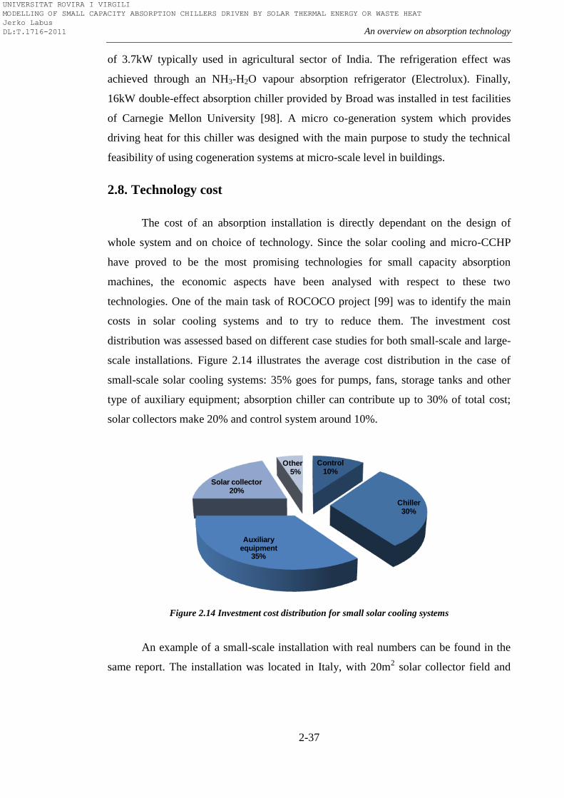
An overview on absorption technology
2-37
of 3.7kW typically used in agricultural sector of India. The refrigeration effect was
achieved through an NH3-H2O vapour absorption refrigerator (Electrolux). Finally,
16kW double-effect absorption chiller provided by Broad was installed in test facilities
of Carnegie Mellon University [98]. A micro co-generation system which provides
driving heat for this chiller was designed with the main purpose to study the technical
feasibility of using cogeneration systems at micro-scale level in buildings.
2.8. Technology cost
The cost of an absorption installation is directly dependant on the design of
whole system and on choice of technology. Since the solar cooling and micro-CCHP
have proved to be the most promising technologies for small capacity absorption
machines, the economic aspects have been analysed with respect to these two
technologies. One of the main task of ROCOCO project [99] was to identify the main
costs in solar cooling systems and to try to reduce them. The investment cost
distribution was assessed based on different case studies for both small-scale and large-
scale installations. Figure 2.14 illustrates the average cost distribution in the case of
small-scale solar cooling systems: 35% goes for pumps, fans, storage tanks and other
type of auxiliary equipment; absorption chiller can contribute up to 30% of total cost;
solar collectors make 20% and control system around 10%.
Figure 2.14 Investment cost distribution for small solar cooling systems
An example of a small-scale installation with real numbers can be found in the
same report. The installation was located in Italy, with 20m2 solar collector field and
Control10%
Chiller30%
Auxiliary equipment
35%
Solar collector20%
Other5%
UNIVERSITAT ROVIRA I VIRGILI MODELLING OF SMALL CAPACITY ABSORPTION CHILLERS DRIVEN BY SOLAR THERMAL ENERGY OR WASTE HEAT Jerko Labus DL:T.1716-2011
Chapter 2
2-38
air-cooled absorption chiller. The cost and the share for each part of solar system are
shown in Table 2.5. Significant savings have been achieved by avoiding storage tanks,
cooling towers and back-up system.
Table 2.5 Investment cost of small solar system in Italy
Auxiliary equipment 5.573 € 19%
Solar collector 10.258 € 35%
Chiller (Rotartica 4.5kW) 9.535 € 32%
Control system 4.050 € 14%
A small-scale solar system with slightly higher cooling capacity and different
design can be found in the paper of Dickinson et al. [100]. 72m2 solar collector array
and 35kW cooling capacity absorption chiller were installed in a government building
in Phoenix, USA. A comparison with previously described system in Italy shows that
different design with auxiliary equipment such as cooling tower and storage tank
significantly increase the investment cost. On the other hand, if we compared the cost of
these two systems per kW of produced cooling capacity, the US installation with 2886
€/kWc seems to be twice cheaper compared to 6537 €/kWc of the Italian installation.
Table 2.6 Investment cost of small solar system in the USA
Auxiliary equipment 29.300 $ (20.510 €) 20%
Solar collector 40.000 $ (28.000 €) 28%
Chiller (Yazaki 35kW) 20.000 $ (14.000 €) 14%
Control ,valves, piping 55.000 $ (38.500€) 38%
Also, approximately 30% should be added to the total sum for installation and
mark-up. Finally, annual costs for maintenance, electricity and water consumption must
be taken into account:
Maintenance: 3.000 €
Electricity: 800 € (based on 35kW cooling capacity chiller sample)
Water consumption: 350 € (35kW cooling capacity chiller)
In order to decrease high investment cost, some companies have started the
production of small pre-fabricated solar cooling systems called solar cooling kits. Solar
cooling kit usually include: solar collectors, hot and cold storage, thermally driven
chiller, cooler and system control. The cost of these kits in Europe is around 4000-4500
UNIVERSITAT ROVIRA I VIRGILI MODELLING OF SMALL CAPACITY ABSORPTION CHILLERS DRIVEN BY SOLAR THERMAL ENERGY OR WASTE HEAT Jerko Labus DL:T.1716-2011
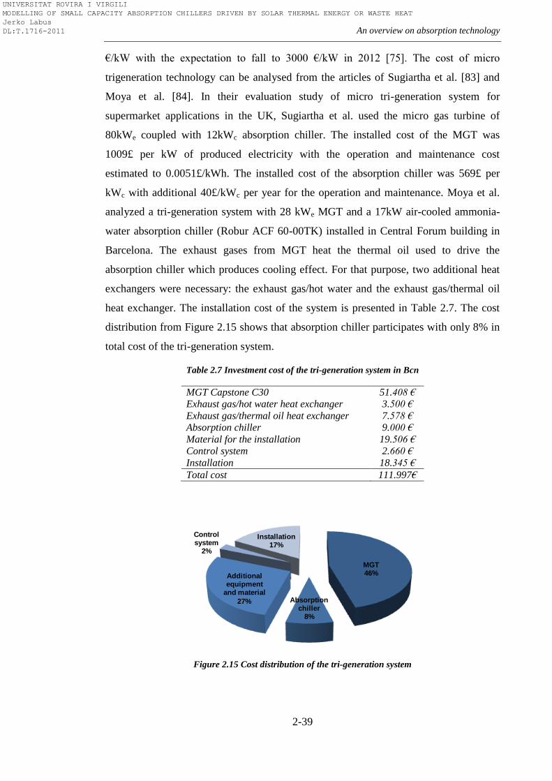
An overview on absorption technology
2-39
€/kW with the expectation to fall to 3000 €/kW in 2012 [75]. The cost of micro
trigeneration technology can be analysed from the articles of Sugiartha et al. [83] and
Moya et al. [84]. In their evaluation study of micro tri-generation system for
supermarket applications in the UK, Sugiartha et al. used the micro gas turbine of
80kWe coupled with 12kWc absorption chiller. The installed cost of the MGT was
1009£ per kW of produced electricity with the operation and maintenance cost
estimated to 0.0051£/kWh. The installed cost of the absorption chiller was 569£ per
kWc with additional 40£/kWc per year for the operation and maintenance. Moya et al.
analyzed a tri-generation system with 28 kWe MGT and a 17kW air-cooled ammonia-
water absorption chiller (Robur ACF 60-00TK) installed in Central Forum building in
Barcelona. The exhaust gases from MGT heat the thermal oil used to drive the
absorption chiller which produces cooling effect. For that purpose, two additional heat
exchangers were necessary: the exhaust gas/hot water and the exhaust gas/thermal oil
heat exchanger. The installation cost of the system is presented in Table 2.7. The cost
distribution from Figure 2.15 shows that absorption chiller participates with only 8% in
total cost of the tri-generation system.
Table 2.7 Investment cost of the tri-generation system in Bcn
MGT Capstone C30 51.408 €
Exhaust gas/hot water heat exchanger 3.500 €
Exhaust gas/thermal oil heat exchanger 7.578 €
Absorption chiller 9.000 €
Material for the installation 19.506 €
Control system 2.660 €
Installation 18.345 €
Total cost 111.997€
Figure 2.15 Cost distribution of the tri-generation system
MGT46%
Absorption chiller
8%
Additional equipment
and material
27%
Control system
2%
Installation17%
UNIVERSITAT ROVIRA I VIRGILI MODELLING OF SMALL CAPACITY ABSORPTION CHILLERS DRIVEN BY SOLAR THERMAL ENERGY OR WASTE HEAT Jerko Labus DL:T.1716-2011
Chapter 2
2-40
From the economical point of view, both small-scale solar cooling systems and
micro-CCHP with absorption chillers are worse than comparable conventional systems
with compression chillers. Despite the relatively high energy savings on annual level,
very high initial cost of these technologies makes them less favourable. Best practice
examples in the case of small solar cooling installation show that 800-2600€ per year
can be saved, depending on load hours, location and system design. Still, payback
period is very long, around 20-30 years without any incentives. With incentives and also
using these systems for DHW and space heating, payback period can be reduced to less
than 10 years. The economic analysis from Moya et al. [101] can be taken as a reference
for energy savings in the case of micro-CCHP. In the case of large residential building,
annual energy savings are 12094€ with a payback period of 5.2 years. This is very close
to the payback period for micro-CCHP system reported in Sugiartha et al. [102] which
is around 6 years. Around 6 years is first-rate payback period under the current
conditions and indicates a very good design of micro-CCHP system. More realistic
scenarios are micro-CCHP systems with payback periods in range of 10-15 years. In
addition to system design, payback period is directly dependant on the number of full
load hours and on the ratio of gas-electricity price. If the current ratio of gas-electricity
price increases from standard 0.3 to 0.4 or more, the payback period will be
significantly reduced. This fact indicates that the right incentives are necessary factor to
make both small-scale solar cooling and micro-CCHP closer to the conventional
technology with compression chillers.
2.9. Regulations and incentives
It has become clear that small capacity absorption machine hardly will be able to
compete with comparable compression machines in the near future if adequate
promotions do not support their further development. This primarily refers to the
integrated energy systems based on renewable energy sources which use absorption
technology: CCHP and solar thermal systems. These systems have a great potential for
saving primary energy (fossil fuels) and to reduce environmental impact.
EU promotes the use of renewable energy for heating and cooling in order to
reduce primary energy dependency and decrease greenhouse gasses emissions.
UNIVERSITAT ROVIRA I VIRGILI MODELLING OF SMALL CAPACITY ABSORPTION CHILLERS DRIVEN BY SOLAR THERMAL ENERGY OR WASTE HEAT Jerko Labus DL:T.1716-2011
An overview on absorption technology
2-41
Following the implementation of Directive 2009/28EC [103], EU member countries
have developed their own strategies and introduced a range of incentives to meet the EU
targets for 2020. A very exhaustive study on existing incentives in EU-27 countries has
been reported by Cansino et al. [104]. According to the authors, the common types of
incentives introduced in the EU countries are: subsidies, tax incentives, financial
support and feed-in tariffs. Technologies based on renewable energy sources such as
biomass, solar, and geothermal can benefit from public subsidies if they are used for
heating and cooling purposes. The most subsidized technology is biomass micro-
cogeneration followed by solar thermal technologies. The promotion of cogeneration is
based on Directive 2004/8/EC of the European Parliament which promotes the high-
efficiency cogeneration based on heat demand and potential benefits of the same with
regard to saving primary energy, avoiding network losses and reducing greenhouse
gasses emissions. Besides subsidies, there are also some regulations which demands
implementation of renewable systems in new buildings. In Germany, there is a
minimum use of 15% of renewable energy for all new buildings while in Spain all
DHW installation have to be with solar thermal energy. Tax deduction, exemptions and
reduced tax rates are other types of public instruments from which CCHP and solar
thermal systems can benefit within the EU. In fact, at the moment there are no special
incentives for CCHP systems but they can benefit from incentives for CHP systems
bearing in mind that CCHP systems are/can be derived from CHP systems. One of the
best examples for tax incentives is Sweden, where households can benefit from 30% tax
credit when converting from direct electric heating and oil-based heating to systems
based on cogeneration or heat pumps. Another example is Italy, where there is a
possibility of reduced VAT (10% instead of 20%) for energy consumption if the
refurbished house includes solar thermal system. Tax exemption from distribution and
consumption taxes on natural gas is present in Spain to promote CHP, regulated by
Royal Decree RD661/2007 [105]. The RD661/2007 promotes biomass green
certificates, where the tariff is valid in the first 15 years and corrections apply after.
Austria, Luxemburg and the UK have feed-in tariffs incentives for heating and cooling
derived from renewable energy sources. Finally, low-interest loans are also type of
incentives which has been offered, for instance, in Germany for the financing of solid
biomass and solar thermal plants for heating and cooling.
UNIVERSITAT ROVIRA I VIRGILI MODELLING OF SMALL CAPACITY ABSORPTION CHILLERS DRIVEN BY SOLAR THERMAL ENERGY OR WASTE HEAT Jerko Labus DL:T.1716-2011
Chapter 2
2-42
Building certification programs like LEED (Leadership in Energy and
Environmental Design) are another way to promote solar cooling and micro-CCHP
systems opportunities. LEED certification, a program introduced by the US Green
Buildings Council is a rating system for buildings which evaluates if the building is
environmentally responsible, operationally efficient and in a healthy environment.
As can be seen, the majority of the energy policies and regulations differ from
country to country due to different patterns of energy demand and supply, fuel prices,
climate and environmental conditions. With respect to that, each country adapted policy
measurements toward its own energy resources and adjusted them to the current
situation. It is evident that progress has been made, but it is still necessary to put more
efforts by making energy policies more consumer-friendly. Finally, of great importance
is to harmonize policies at local, national and international levels in order to facilitate
the further development of renewable energy based technologies, especially solar
thermal and micro-CCHP technologies.
2.10. Potential and barriers
The potential on the field of primary energy savings and environmental benefits
are the main advantages which encourage further development of small capacity
absorption machines. Reduced electricity consumption and low CO2 emission has been
confirmed by numerous studies. Beside the space cooling and refrigeration purposes, it
is also possible to use small capacity absorption machines for DHW production and
space heating. Also, there is a possibility to use them in remote and isolated areas where
the infrastructure does not meet energy requirements. Very promising application are
supermarkets and small agro-food industry applications. Very intensive researches on
this topic and numerous studies have pointed to solar thermal and micro-CHCP
technologies as the main carriers for future development of small capacity absorption
machines. It seems that these two technologies are the right path which can lead to the
economic attractiveness of small capacity absorption machines, making them
competitive with conventional compression machines. However, the problem is that the
both solar thermal and micro-CHCP technologies are still under development. It is truth
that several micro-CHP units such as gas micro turbines and fuel cells which can be
UNIVERSITAT ROVIRA I VIRGILI MODELLING OF SMALL CAPACITY ABSORPTION CHILLERS DRIVEN BY SOLAR THERMAL ENERGY OR WASTE HEAT Jerko Labus DL:T.1716-2011
An overview on absorption technology
2-43
coupled with small absorption machines are now available at the market, but the cost is
high. In the field of solar collectors has been made a great progress in the last few years
which resulted in much accessible prices. Overall progress is evident; however, there
are still lots of obstacles that impede the full expansion of small absorption machines.
The main obstacle remains the high first cost and lack of serial production, which would
inevitably lead to price reduction. The lower performance is another obstacle, small
absorption machines are mainly single-stage with the COP lower than comparable
compression units (0.7 compared to around 3). However, the first commercial small
absorption double-stage unit looks promising with respect to the efficiency. There are
many factors that affect the efficiency and effectiveness of the systems with small
capacity absorption machines. Design and sizing are of great importance. The minimum
solar fraction of around 50% is necessary that solar thermal system with single-stage
absorption chiller starts saving primary energy. This indicates the need for increased
number of hours operating at full load. Full load operation stands for micro-CHCP
systems as well. The energy storage is another factor to which has been devoted a lot of
research attention lately. In order to prevent inefficient systems, it is necessary to
optimize the electricity consumption of external system components such as cooling
towers. This is why the control is very important factor. On the other hand, the control
also has to be simple in order to decrease the high first cost. Progress and cost reduction
of electronic components for control should contribute to that. As already mentioned
above, new opportunities have been introduced with small solar kits which make small
absorption machines more accessible. The potential for further cost reduction of small
solar kits has been presented by Mugnier [93]. The cost of solar collectors and storage
could be lowered for 10% in the next 2-3 years. The cost reduction potential for
(ab)sorption chillers is around 20% with new components, with possibility to increase
up to 50% if serial production starts (more than 500 units). The price of the re-cooler
could also decrease up to 50%. The price for installation can decrease up to 30%
through standardized solar cooling kits. The control has the most promising potential for
reduction, more than 60%.
Two very important factors for further development are lobbying and subsidies.
The financial incentives for the installation of these systems are another important factor
which may be a driving force for successful market penetration. However, maybe the
UNIVERSITAT ROVIRA I VIRGILI MODELLING OF SMALL CAPACITY ABSORPTION CHILLERS DRIVEN BY SOLAR THERMAL ENERGY OR WASTE HEAT Jerko Labus DL:T.1716-2011

Chapter 2
2-44
most important issue is to create a sense of responsibility among people about the fatal
ecological consequences that can bring increasing use of electric cooling systems.
At the end, all the facts mentioned above indicate that small capacity absorption
machines have a good potential for further development under the two emerging
technologies such as solar thermal and micro-CHCP, but a lot of research work is
ahead. Appropriate standards, test procedures and best practices guides together with
intensified work on simulations, optimization and control strategies improvement are
some of the needs which are necessary to accelerate the progress and to fill the gap with
respect to the conventional systems.
UNIVERSITAT ROVIRA I VIRGILI MODELLING OF SMALL CAPACITY ABSORPTION CHILLERS DRIVEN BY SOLAR THERMAL ENERGY OR WASTE HEAT Jerko Labus DL:T.1716-2011
3-1
Chapter 3
Multifunctional test bench
“A journey of a thousand miles must begin with a single step.”
Lao Tzu
3.1. Introduction
For the purpose of performance analysis of different solar assisted and thermally
driven technologies, an experimental test facility has been constructed at the
laboratories of the University Rovira i Virgili (URV) in Tarragona, Spain. This, so-
called ―Multifunctional test bench‖ serves as a test stand for the scientific investigation
of small-scale and mid-scale absorption equipment in particular, but also provides
possibilities to test a variety of equipment used in HVAC systems, solar assisted air-
conditioning and CHP application. A complete range of pilot scale equipment enables
comprehensive testing of different units in order to select the most suitable technology
for application of interest. Tests with thermally driven water-cooled4 an air-cooled
chillers and water-to-water and air-to-water heat pumps, electrically driven (vapour
compression) water(air)-cooled chillers and water(air)-to-water heat pumps, Organic
Rankin Cycle engines, fuel cells, gas micro turbines, internal combustion engines,
multiple chillers operations, micro-cogeneration systems and evaporating desalination
equipment are some of the operations which can be performed inside this
multifunctional test bench. However, bearing in mind that the aim of this thesis is
addressed to thermally driven chillers and heat pumps the main focus will be on
absorption cooling and heating facilities.
The analysis of real benefits of equipment is usually performed by independent
laboratories under conditions of operation based on predetermined standard. This
ensures that the test was carried out under a certain quality requirements and the results
obtained by this method are accurate. On the other hand, these tests are costly and time
consuming. Normally, to balance these facts, almost all the equipment is analysed under
4 The terminology is in accordance with [106]
UNIVERSITAT ROVIRA I VIRGILI MODELLING OF SMALL CAPACITY ABSORPTION CHILLERS DRIVEN BY SOLAR THERMAL ENERGY OR WASTE HEAT Jerko Labus DL:T.1716-2011
Chapter 3
3-2
the same conditions of operation in steady-state regime and with reduced number of
tests. Standardization makes things easier when selecting the equipment type and size
for particular system application, but only in the design stage. It is sufficient to choose
type of equipment based on design demand and nominal conditions of the equipment,
but it does not carry complete information about the equipment performance. Everyday
practice confirms that the selection of appropriate equipment for a particular application
can be very cumbersome task, when almost certainly the temperatures or thermal loads
are not constant over time. This idea was one of the key factors in designing this
multifunctional test bench. To create useful tool which will help to evaluate the benefits
of both new designed equipment and equipment already existing on the market,
analysing entire operating range and complying with existing standard at the same time.
Complete performance map of the equipment, based on real data and taken under
standardized procedure, might be useful in various ways: through simulation models
and software packages, fault detection or for control purposes (e.g., model based
control). In fact, a complete performance map of the equipment should be available
always when it is likely to be employed in some cooling and heating systems
application.
According to Gordon and Ng [107], when planning and designing test facility
for conducting standard and application rating tests for chillers and heat pumps, two
possible approaches can be considered, depending on one’s needs. First approach is the
black-box approach, where the chillers’ (heat pump’s) performance is inferred based on
state measurements of external fluid circuits. In other words, the internal states of the
refrigerant and solution are not measured and performance evaluation of the machine
comes from steady state performance at a specified set of external flow rates and
inlet/outlet temperatures. Second approach involves internal thermodynamic states of
refrigerant and solution circuits as well as the state measurements of external fluid
circuits. This, more complex feature, is applied when the computation of essential
chillers’ characteristics is needed and the black-box approach is insufficient. Values of
the heat exchanger thermal conductance, working pair concentrations, internal process
temperatures and flow rates are some of the measurements included in this intrusive
approach. This additional information is necessary especially when designing and
developing new equipment. By means of establishing the link between the states of
UNIVERSITAT ROVIRA I VIRGILI MODELLING OF SMALL CAPACITY ABSORPTION CHILLERS DRIVEN BY SOLAR THERMAL ENERGY OR WASTE HEAT Jerko Labus DL:T.1716-2011
Multifunctional test bench
3-3
external fluids and system losses, the diagnostic capability can be used to adjust key
component variables.
URV multifunctional test bench lies on both black-box and internal
measurement approaches. Mainly, multifunctional test bench uses black-box approach
to obtain performance evaluation of the chiller (heat pump) based only on external
measurements. This type of experimental facilities is preferred in work with commercial
equipment, when chillers are tested according to commercial standards. Also, the
internal measurement approach is easily achievable using the same test bench equipped
with some additional measuring equipment in order to define internal behaviour of the
chiller (heat pump).
In general, there are two kind of standards developed for chillers and heat
pumps:
(1) Commercial standards, which are issued by professional engineers
society, industrial bodies or international institutes, and
(2) Statutory standards, which are issued by governmental organization
Commercial standards rely more on the thermal performance while statutory
standards relate more to the mechanical integrity and robustness of the machine.
Whereas the commercial standards deal with thermodynamic performance, full attention
will be paid to this type of standards.
3.2. Absorption system standards
As mentioned above, standards play an important role in order to provide a
valuable basis for machine evaluation prior to their release to the market, but also in
applications, simulations and control issues. Among worldwide known and recognized
institutions and standard issuing organizations such as American Society for Heating
and Refrigeration Engineers (ASHRAE), the American Air-Conditioning, Heating and
Refrigeration Institute (AHRI), the International Institute of Refrigeration (IIR),
European Committee for Standardization (CEN), Australian Building Code Board
(ABCB) there are only a few standards dealing with absorption systems. In particular,
UNIVERSITAT ROVIRA I VIRGILI MODELLING OF SMALL CAPACITY ABSORPTION CHILLERS DRIVEN BY SOLAR THERMAL ENERGY OR WASTE HEAT Jerko Labus DL:T.1716-2011
Chapter 3
3-4
there are only three available standards. First, issued by AHRI [108], which applies to
water-cooled steam and hot-water operated water chilling units. Second, recommended
by CEN [109, 110] for gas fired sorption air-conditioning and heat pump appliances
with a heat input lower than 70kW. And third, JIS B 8622, the Standard for water-LiBr
absorption refrigeration machines issued by Japanese Standards Association [111]
which is beyond our limits due to language barrier.
3.3. AHRI/ANSI 560-2000
The AHRI/ANSI Standard 560-2000 applies to water-cooled single-effect steam
chillers, water-cooled single-effect hot water chillers, water-cooled double-effect steam
chillers, water-cooled double-effect hot water chillers, and water cooled double-effect
direct-fired chillers with water-LiBr working pair.
Standard rating conditions:
Entering condenser water temperature: 29.4 °C
Condenser water flow rate: 0.065 L/s per kW of cooling (SE indirect
fired), 0.072 L/s per kW (DE indirect fired, DE direct-fired)
Condenser water-side fouling factor: 0.000044 m2°C/W
Evaporator leaving water temperature: 6.7°C
Evaporator water flow rate: 0.043 L/s per kW
Evaporator waterside fouling factor: 0.000018 m2°C/W
Tube-side fouling factor (steam): 0.000 m2°C/W (indirect fired)
Tube-side fouling factor (hot water): 0.00018 m2°C/W (indirect fired)
UNIVERSITAT ROVIRA I VIRGILI MODELLING OF SMALL CAPACITY ABSORPTION CHILLERS DRIVEN BY SOLAR THERMAL ENERGY OR WASTE HEAT Jerko Labus DL:T.1716-2011
Multifunctional test bench
3-5
Test Procedure
After installing the equipment in accordance with the manufacturer’s
instructions and non-condensables have been removed, start the system to reach steady
state conditions within the following tolerances and instructions:
The water flow rate in external circuits shall not deviate more than ±5%
from the specified value
The individual readings of water temperature in external circuits shall
not vary from the specified values by more than 0.3ºC
The leaving chilled water temperature, the entering absorber/condenser
water temperature and the leaving hot water temperature shall be
adjusted by an increment corresponding to the specified Field Fouling
Allowance required for test
Part-load tests for water chilling packages which have continuous
capacity modulation must be taken within ± 2% of the full load at the
specified part-load capacity
Steam supply pressure shall be maintained within ±1.4kPa for SE and ±
14kPa for DE of the specified pressure
Gas and oil heating values to be used for testing are as measured or
verified by supplier. Flue gas back pressure shall be maintained within
range specified by the manufacturer
Chiller package shall be supplied with nameplate voltage and frequency
After steady-state conditions have been established at the specific set of
conditions and within the defined tolerance, three sets of data shall be taken, at a
minimum of 5 minute intervals, as simultaneously as possible.
UNIVERSITAT ROVIRA I VIRGILI MODELLING OF SMALL CAPACITY ABSORPTION CHILLERS DRIVEN BY SOLAR THERMAL ENERGY OR WASTE HEAT Jerko Labus DL:T.1716-2011
Chapter 3
3-6
Measurements to be recorded
a) Temperatures of water entering/ leaving components at each one of the
external water circuits, [ºC]
b) Evaporator, absorber/condenser and generator water flow rate, [kg/s]
c) Heat Energy Input from one of the following:
Steam consumption [kg/hr], steam supply pressure [kPa], steam
supply temperature [ºC], steam condensate temperature [ºC]
Hot water flow rate [kg/s], hot water supply temperature [ºC], hot
water leaving temperature [ºC]
Gas consumption [m3/hr], Higher Heating Value, HHV, gas
pressure entering gas [kPa]
d) Water pressure drop in evaporator, absorber/condenser and generator
(hot water fired units), [kPa]
e) Electric consumption, [kW]
f) Ambient temperature at test site, [ºC]
g) Barometric pressure at test site, [kPa]
h) Nameplate data, model and serial number of tested equipment
i) Date, place and time of test
Method for Simulating Field Fouling Allowance
Due to the fact that dirtiness at the surface of heat exchangers tends to reduce
capacity and increase energy consumption, water-side fouling factor allowance
represents an important factor when dealing with chillers (heat pumps). AHRI 560-2000
recommends the following procedure to analyse the effect of the fouling factor
allowance on heat transfer surface:
UNIVERSITAT ROVIRA I VIRGILI MODELLING OF SMALL CAPACITY ABSORPTION CHILLERS DRIVEN BY SOLAR THERMAL ENERGY OR WASTE HEAT Jerko Labus DL:T.1716-2011
Multifunctional test bench
3-7
The log mean temperature difference can be obtained from equation 3.1:
(
(3.1)
The incremental log mean temperature difference (ILMD) is now determined
using the equation 3.2:
(3.2)
where:
twe ,tw1- entering/leaving water temperature
ts- saturation temperature
- specified field fouling allowance
q - component load
A - total heat transfer surface area
Next step is to calculate water temperature difference, needed to simulate the
additional fouling (equations 3.3 and 3.4):
(3.3)
(3.4)
where:
(3.5)
UNIVERSITAT ROVIRA I VIRGILI MODELLING OF SMALL CAPACITY ABSORPTION CHILLERS DRIVEN BY SOLAR THERMAL ENERGY OR WASTE HEAT Jerko Labus DL:T.1716-2011
Chapter 3
3-8
(3.6)
Ssp, Sc - small temperature difference as specified/in cleaned condition
The water temperature difference is then added to the absorber/condenser
entering water temperature or subtracted from the evaporator leaving water temperature
to simulate the additional fouling factor.
Energy calculus and Heat Balance – Substantiating Test
The heat loads in the absorption chiller components can be calculated by general
equation where q is equal to the product of water flow rate (or using the product of
volumetric flow rate and density instead of mass flow rate), the water temperature
difference between entering and leaving water and the specific heat of water (Cp) as
shown in the following equation:
(3.7)
In case when energy supply in generator comes from gas or other type of fuel,
generator heat load is calculated according to equation 3.8:
(3.8)
where:
mF - fuel mass flow rate [kg/s]
HHV- Higher Heating Value [kJ/kg]
According to the Heat Balance Substantiating Test, all heat that enters the
absorption unit should be equal to all heat that leaves. However, due to the heat losses
or heat gains caused by radiation and convection may cause that overall heat balance
differs from zero. The following equation 3.9 serves to calculate heat balance with
omitted heat losses and gains:
UNIVERSITAT ROVIRA I VIRGILI MODELLING OF SMALL CAPACITY ABSORPTION CHILLERS DRIVEN BY SOLAR THERMAL ENERGY OR WASTE HEAT Jerko Labus DL:T.1716-2011
Multifunctional test bench
3-9
(3.9)
where:
qhs - Input from heat source (generator heat load)
qev - Net cooling capacity (evaporator heat load)
qc - Heat rejection to the cooling tower (absorber/condenser heat load)
In practice, heat losses caused by radiation and convection have the value that
cannot be omitted. Therefore, for any test of water-cooled chiller to be acceptable, the
heat balance (%) shall be within the allowable tolerance calculated by equation 3.10:
(3.10)
where:
FL - Full load
DTFL- Difference between entering and leaving chilled water temperature at full load
Part-Load ratings
The intent of part load ratings is to permit the performance over a range of
operating conditions. Energy efficiency of the absorption unit is determined through
Coefficient of Performance (COP). COP is defined as a ratio cooling/heating capacity to
the power input at any given set of rating conditions. Considering that chillers rarely
operate at their maximum capacity, Integrated Part Load Value method was developed
to provide consistent method for calculating single number part-load performance
number for water-chilling products. This method requires that the unit efficiency be
determined at 100%, 75%, 50%, 25% of standard ratings. The study of American
Department of Energy [112], based on weighted average of 29 different cities across the
USA with the most common building types and operations was used to develop a chiller
UNIVERSITAT ROVIRA I VIRGILI MODELLING OF SMALL CAPACITY ABSORPTION CHILLERS DRIVEN BY SOLAR THERMAL ENERGY OR WASTE HEAT Jerko Labus DL:T.1716-2011
Chapter 3
3-10
loading profile for a typical year. The resulting chiller loading profile is at 100%
capacity about 1% of the time, 75% capacity about 42% of the time, 50% capacity about
45% of the time, and 25% capacity about 12% of the time. These constants are
incorporated into the IPLV equation (3.11):
For COP:
(3.11)
where:
A - COP at 100% capacity (condenser water at 29.4°C)
B - COP at 75% capacity (condenser water at 25.3°C)
C - COP at 50% capacity (condenser water at 21.1°C)
D - COP at 25% capacity (condenser water at 21.1°C)
IPLV provides the most accurate average chiller energy usage for evaluation of
different chiller energy usage. IPLV becomes non-standard part load value (NPLV)
method is used when the known parameters differ from standard ratings, having the
manufacturers’ recommended value.
3.4. EN 12309:2000
The European Standard EN 12309:2000 issued by CEN refers to gas-fired
sorption air-conditioning and heat pump machines with heat input less than 70kW.
Term sorption here covers the absorption and adsorption equipment. This standard
applies only to machines with following characteristics: integral burner under the
control of fully automatic burner control systems; closed refrigerant circuits in which
the refrigerant does not come into direct contact with the fluid to be cooled (heated) and
where mechanical means to assist transportation of the combustion air. Three different
types of the machines can be distinguished by this standard depending on their primary
function:
UNIVERSITAT ROVIRA I VIRGILI MODELLING OF SMALL CAPACITY ABSORPTION CHILLERS DRIVEN BY SOLAR THERMAL ENERGY OR WASTE HEAT Jerko Labus DL:T.1716-2011
Multifunctional test bench
3-11
Chiller: air-conditioning machine designed to provide cooling as primary
function and may provide heating as a secondary function
Chiller/heater: air-conditioning machine designed to provide cooling and
heating both as primary function
Heat pump appliance: heating machine utilizing a refrigerant to transfer
heat from one medium to another at a higher temperature in order to
contribute to the heating function also
Besides, depending on which heat transfer medium (air or water) is used for
absorber/condenser, this standard denominates air-cooled and water-cooled machines.
Part 1 of this standard specifies the requirements and test methods for the safe usage of
this equipment. Whereas it covers only the gas-fired equipment, gases are classified into
three families and divided into groups according to Wobbe index. Based on that,
machines are classified according to the gases they use; the mode of evacuation of
combustion products; temperature of their heat transfer media and their denomination.
In addition, Part 1 covers all the relevant issue concerning construction, safety, marking,
installation, work and maintenance of this equipment. This includes materials and
methods of construction, thermal insulation, gas connection, soundness, operational
safety in the event of fluctuation and interruption, requirements for adjusting, control
and safety devices, ignition devices, transportation of combustion air and flue gasses,
flame supervision system, operational requirements, test methods and technical
instructions for installation and adjustment, use and maintenance and servicing.
To be in accordance with this standard, all heat inputs should be determined
from the volumetric flow rate (V0) or mass rate (M0) which relate to the rate obtained
with reference gas under reference test conditions (dry gas, 15ºC, 1013.25 mbar). The
heat input (Q0) can be calculated by one of following formulas (3.12a, 3.12b):
(3.12a)
(3.12b)
UNIVERSITAT ROVIRA I VIRGILI MODELLING OF SMALL CAPACITY ABSORPTION CHILLERS DRIVEN BY SOLAR THERMAL ENERGY OR WASTE HEAT Jerko Labus DL:T.1716-2011
Chapter 3
3-12
where:
V0 - volumetric flow rate [m3/h] obtained at reference conditions
M0 - mass input [kg/h] obtained at reference conditions
Hi - net calorific value of the reference gas [MJ/m3; MJ/kg]
Hs - gross calorific value of the reference gas [MJ/m3; MJ/kg]
In practice, the values obtained in test do not correspond to these reference
conditions so they should be corrected to bring them to the values that would actually
have been obtained if these reference conditions had existed at the injector outlet
(equations 3.12c and 3.12d).
(3.12c)
(3.12d)
where:
QT - heat input under the test conditions [kW]
VC - volumetric flow rate [m3/h] of dry test gas corrected to reference conditions
Vm - measured volumetric flow rate [m3/h]
pa - atmospheric pressure [mbar]
p - gas supply pressure at the gas meter [mbar]
pw - partial vapour pressure [mbar]
tg - gas temperature at the gas meter [ºC]
Part 2 of this standard relates to requirements and methods of test for the rational
use of energy. Prior to start with rating tests, the test installation has to be designed in
UNIVERSITAT ROVIRA I VIRGILI MODELLING OF SMALL CAPACITY ABSORPTION CHILLERS DRIVEN BY SOLAR THERMAL ENERGY OR WASTE HEAT Jerko Labus DL:T.1716-2011
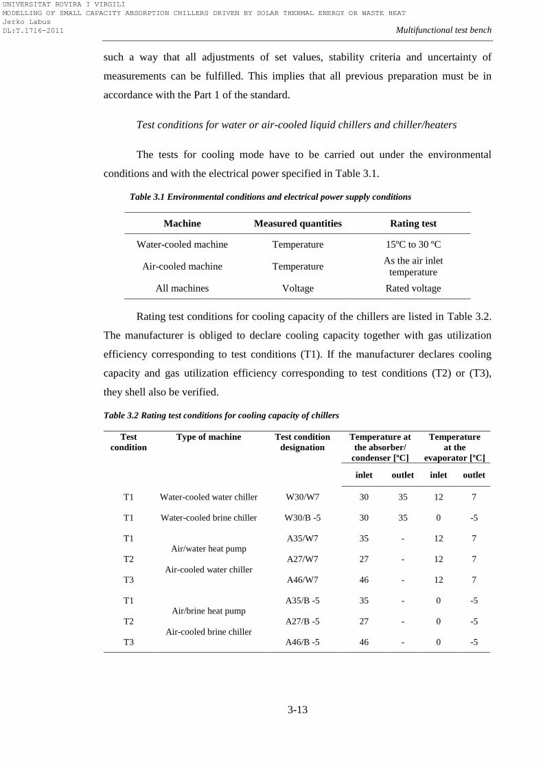
Multifunctional test bench
3-13
such a way that all adjustments of set values, stability criteria and uncertainty of
measurements can be fulfilled. This implies that all previous preparation must be in
accordance with the Part 1 of the standard.
Test conditions for water or air-cooled liquid chillers and chiller/heaters
The tests for cooling mode have to be carried out under the environmental
conditions and with the electrical power specified in Table 3.1.
Table 3.1 Environmental conditions and electrical power supply conditions
Machine Measured quantities Rating test
Water-cooled machine Temperature 15ºC to 30 ºC
Air-cooled machine Temperature As the air inlet
temperature
All machines Voltage Rated voltage
Rating test conditions for cooling capacity of the chillers are listed in Table 3.2.
The manufacturer is obliged to declare cooling capacity together with gas utilization
efficiency corresponding to test conditions (T1). If the manufacturer declares cooling
capacity and gas utilization efficiency corresponding to test conditions (T2) or (T3),
they shell also be verified.
Table 3.2 Rating test conditions for cooling capacity of chillers
Test
condition
Type of machine Test condition
designation
Temperature at
the absorber/
condenser [ºC]
Temperature
at the
evaporator [ºC]
inlet outlet inlet outlet
T1 Water-cooled water chiller W30/W7 30 35 12 7
T1 Water-cooled brine chiller W30/B -5 30 35 0 -5
T1 Air/water heat pump
Air-cooled water chiller
A35/W7 35 - 12 7
T2 A27/W7 27 - 12 7
T3 A46/W7 46 - 12 7
T1 Air/brine heat pump
Air-cooled brine chiller
A35/B -5 35 - 0 -5
T2 A27/B -5 27 - 0 -5
T3 A46/B -5 46 - 0 -5
UNIVERSITAT ROVIRA I VIRGILI MODELLING OF SMALL CAPACITY ABSORPTION CHILLERS DRIVEN BY SOLAR THERMAL ENERGY OR WASTE HEAT Jerko Labus DL:T.1716-2011
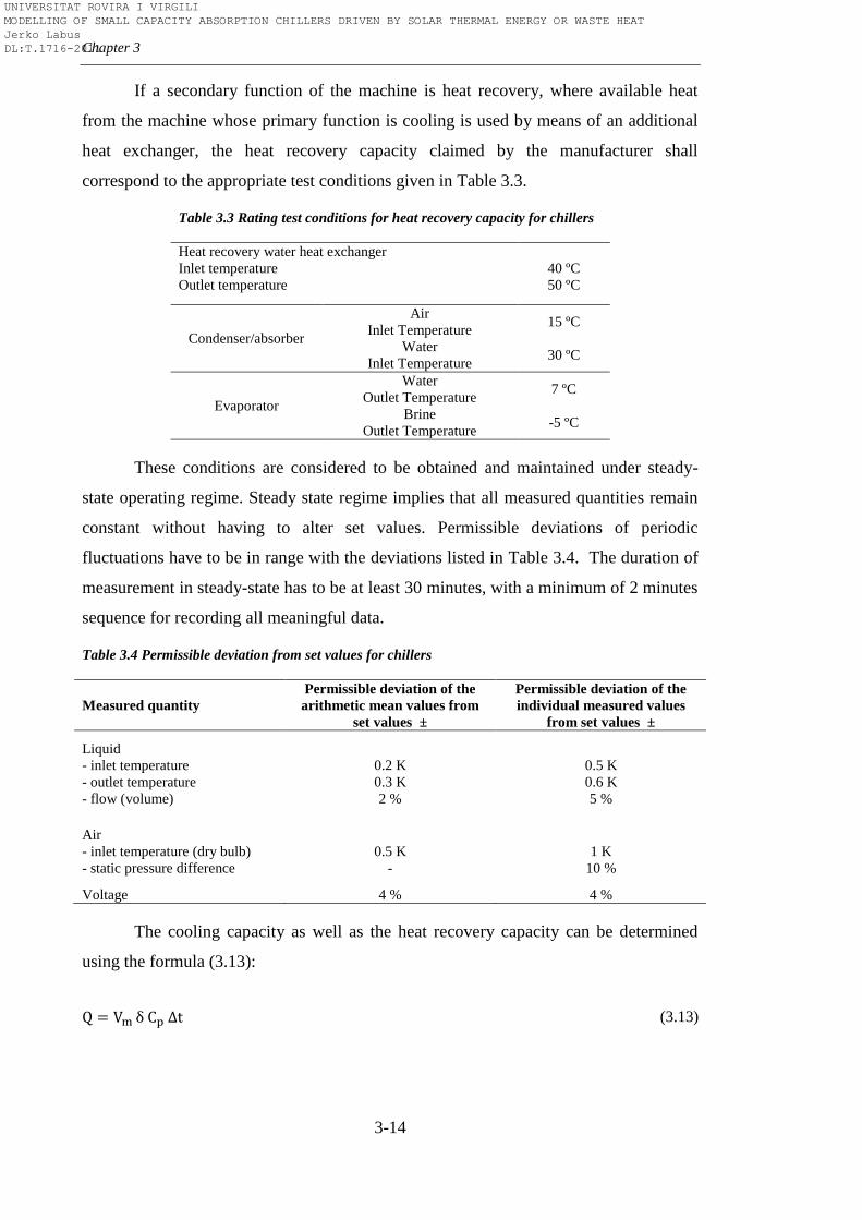
Chapter 3
3-14
If a secondary function of the machine is heat recovery, where available heat
from the machine whose primary function is cooling is used by means of an additional
heat exchanger, the heat recovery capacity claimed by the manufacturer shall
correspond to the appropriate test conditions given in Table 3.3.
Table 3.3 Rating test conditions for heat recovery capacity for chillers
Heat recovery water heat exchanger
Inlet temperature
Outlet temperature
40 ºC
50 ºC
Condenser/absorber
Air
Inlet Temperature 15 ºC
Water
Inlet Temperature 30 ºC
Evaporator
Water
Outlet Temperature 7 ºC
Brine
Outlet Temperature -5 ºC
These conditions are considered to be obtained and maintained under steady-
state operating regime. Steady state regime implies that all measured quantities remain
constant without having to alter set values. Permissible deviations of periodic
fluctuations have to be in range with the deviations listed in Table 3.4. The duration of
measurement in steady-state has to be at least 30 minutes, with a minimum of 2 minutes
sequence for recording all meaningful data.
Table 3.4 Permissible deviation from set values for chillers
Measured quantity
Permissible deviation of the
arithmetic mean values from
set values ±
Permissible deviation of the
individual measured values
from set values ±
Liquid
- inlet temperature
- outlet temperature
- flow (volume)
0.2 K
0.3 K
2 %
0.5 K
0.6 K
5 %
Air
- inlet temperature (dry bulb)
- static pressure difference
0.5 K
-
1 K
10 %
Voltage 4 % 4 %
The cooling capacity as well as the heat recovery capacity can be determined
using the formula (3.13):
(3.13)
UNIVERSITAT ROVIRA I VIRGILI MODELLING OF SMALL CAPACITY ABSORPTION CHILLERS DRIVEN BY SOLAR THERMAL ENERGY OR WASTE HEAT Jerko Labus DL:T.1716-2011
Multifunctional test bench
3-15
where:
Q - cooling/heat recovery capacity [kW]
Vm - volumetric flow rate of the heat transfer medium at inlet temperature [m3/s]
- density of the heat transfer medium at inlet temperature [kg/m3]
Cp - specific heat of the heat transfer medium at constant pressure at mean temperature
of the heat transfer medium [kJ/kg K]
- difference between inlet and outlet temperatures of the heat transfer medium [K]
The gas utilization efficiency (ηc) is determined by equation 3.14:
(3.14)
where:
QC - cooling capacity [kW]
QT - heat input of the burner under the test conditions [kW]
Standard specifies also similar procedure for testing air-cooled or water-cooled
air conditioners as well as for machines in heating mode where both output
measurements with and without defrosting are covered. Complete procedure and
detailed explanation of the requirements for different gas-fired machines can be found
in cited references.
Although at first sight seems that these standards are sufficient to cover whole
field of absorption systems, simple analysis shows that still there are many uncovered
topics. AHRI/ANSI 560-2000, as seen above, covers a wide area of water-cooled
absorption chilling and chilling/heating units, both direct and indirect fired. However,
this standard is not valid for air-cooled machines, heat pumps and exhaust gas fired
applications. On the other hand, EN 12309-1&2:2000 covers this area but only for
small-scale gas fired units. Hence the question raises how to treat indirect fired air-
UNIVERSITAT ROVIRA I VIRGILI MODELLING OF SMALL CAPACITY ABSORPTION CHILLERS DRIVEN BY SOLAR THERMAL ENERGY OR WASTE HEAT Jerko Labus DL:T.1716-2011
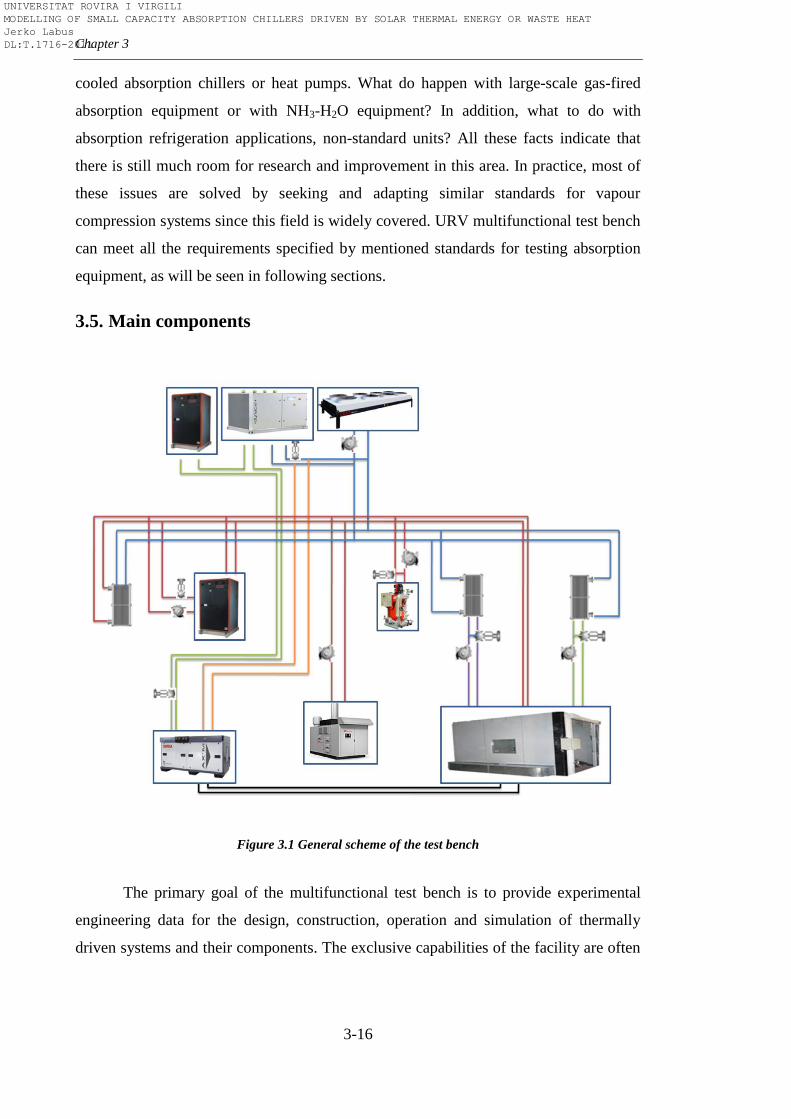
Chapter 3
3-16
cooled absorption chillers or heat pumps. What do happen with large-scale gas-fired
absorption equipment or with NH3-H2O equipment? In addition, what to do with
absorption refrigeration applications, non-standard units? All these facts indicate that
there is still much room for research and improvement in this area. In practice, most of
these issues are solved by seeking and adapting similar standards for vapour
compression systems since this field is widely covered. URV multifunctional test bench
can meet all the requirements specified by mentioned standards for testing absorption
equipment, as will be seen in following sections.
3.5. Main components
Figure 3.1 General scheme of the test bench
The primary goal of the multifunctional test bench is to provide experimental
engineering data for the design, construction, operation and simulation of thermally
driven systems and their components. The exclusive capabilities of the facility are often
UNIVERSITAT ROVIRA I VIRGILI MODELLING OF SMALL CAPACITY ABSORPTION CHILLERS DRIVEN BY SOLAR THERMAL ENERGY OR WASTE HEAT Jerko Labus DL:T.1716-2011
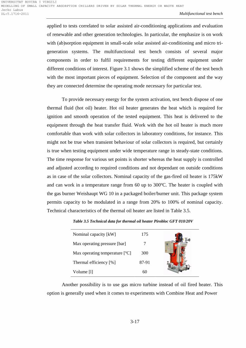
Multifunctional test bench
3-17
applied to tests correlated to solar assisted air-conditioning applications and evaluation
of renewable and other generation technologies. In particular, the emphasize is on work
with (ab)sorption equipment in small-scale solar assisted air-conditioning and micro tri-
generation systems. The multifunctional test bench consists of several major
components in order to fulfil requirements for testing different equipment under
different conditions of interest. Figure 3.1 shows the simplified scheme of the test bench
with the most important pieces of equipment. Selection of the component and the way
they are connected determine the operating mode necessary for particular test.
To provide necessary energy for the system activation, test bench dispose of one
thermal fluid (hot oil) heater. Hot oil heater generates the heat which is required for
ignition and smooth operation of the tested equipment. This heat is delivered to the
equipment through the heat transfer fluid. Work with the hot oil heater is much more
comfortable than work with solar collectors in laboratory conditions, for instance. This
might not be true when transient behaviour of solar collectors is required, but certainly
is true when testing equipment under wide temperature range in steady-state conditions.
The time response for various set points is shorter whereas the heat supply is controlled
and adjusted according to required conditions and not dependant on outside conditions
as in case of the solar collectors. Nominal capacity of the gas-fired oil heater is 175kW
and can work in a temperature range from 60 up to 300ºC. The heater is coupled with
the gas burner Weishaupt WG 10 in a packaged boiler/burner unit. This package system
permits capacity to be modulated in a range from 20% to 100% of nominal capacity.
Technical characteristics of the thermal oil heater are listed in Table 3.5.
Table 3.5 Technical data for thermal oil heater Pirobloc GFT 010/20V
Nominal capacity [kW] 175
Max operating pressure [bar] 7
Max operating temperature [ºC] 300
Thermal efficiency [%] 87-91
Volume [l] 60
Another possibility is to use gas micro turbine instead of oil fired heater. This
option is generally used when it comes to experiments with Combine Heat and Power
UNIVERSITAT ROVIRA I VIRGILI MODELLING OF SMALL CAPACITY ABSORPTION CHILLERS DRIVEN BY SOLAR THERMAL ENERGY OR WASTE HEAT Jerko Labus DL:T.1716-2011
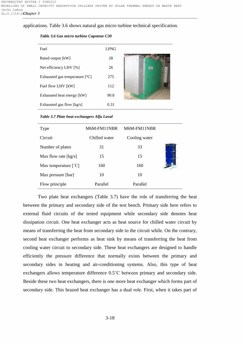
Chapter 3
3-18
applications. Table 3.6 shows natural gas micro turbine technical specification.
Table 3.6 Gas micro turbine Capstone C30
Fuel LPNG
Rated output [kW] 28
Net efficiency LHV [%] 26
Exhausted gas temperature [ºC] 275
Fuel flow LHV [kW] 112
Exhausted heat energy [kW] 90.8
Exhausted gas flow [kg/s] 0.31
Table 3.7 Plate heat exchangers Alfa Laval
Type M6M-FM11NBR M6M-FM11NBR
Circuit Chilled water Cooling water
Number of plates 31 33
Max flow rate [kg/s] 15 15
Max temperature [˚C] 160 160
Max pressure [bar] 10 10
Flow principle Parallel Parallel
Two plate heat exchangers (Table 3.7) have the role of transferring the heat
between the primary and secondary side of the test bench. Primary side here refers to
external fluid circuits of the tested equipment while secondary side denotes heat
dissipation circuit. One heat exchanger acts as heat source for chilled water circuit by
means of transferring the heat from secondary side to the circuit while. On the contrary,
second heat exchanger performs as heat sink by means of transferring the heat from
cooling water circuit to secondary side. These heat exchangers are designed to handle
efficiently the pressure difference that normally exists between the primary and
secondary sides in heating and air-conditioning systems. Also, this type of heat
exchangers allows temperature difference 0.5˚C between primary and secondary side.
Beside these two heat exchangers, there is one more heat exchanger which forms part of
secondary side. This brazed heat exchanger has a dual role. First, when it takes part of
UNIVERSITAT ROVIRA I VIRGILI MODELLING OF SMALL CAPACITY ABSORPTION CHILLERS DRIVEN BY SOLAR THERMAL ENERGY OR WASTE HEAT Jerko Labus DL:T.1716-2011
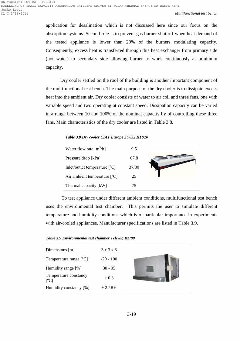
Multifunctional test bench
3-19
application for desalination which is not discussed here since our focus on the
absorption systems. Second role is to prevent gas burner shut off when heat demand of
the tested appliance is lower than 20% of the burners modulating capacity.
Consequently, excess heat is transferred through this heat exchanger from primary side
(hot water) to secondary side allowing burner to work continuously at minimum
capacity.
Dry cooler settled on the roof of the building is another important component of
the multifunctional test bench. The main purpose of the dry cooler is to dissipate excess
heat into the ambient air. Dry cooler consists of water to air coil and three fans, one with
variable speed and two operating at constant speed. Dissipation capacity can be varied
in a range between 10 and 100% of the nominal capacity by of controlling these three
fans. Main characteristics of the dry cooler are listed in Table 3.8.
Table 3.8 Dry cooler CIAT Europe 2 9032 HI 920
Water flow rate [m3/h] 9.5
Pressure drop [kPa] 67.8
Inlet/outlet temperature [˚C] 37/30
Air ambient temperature [˚C] 25
Thermal capacity [kW] 75
To test appliance under different ambient conditions, multifunctional test bench
uses the environmental test chamber. This permits the user to simulate different
temperature and humidity conditions which is of particular importance in experiments
with air-cooled appliances. Manufacturer specifications are listed in Table 3.9.
Table 3.9 Environmental test chamber Telewig KZ/80
Dimensions [m] 3 x 3 x 3
Temperature range [ºC] -20 - 100
Humidity range [%] 30 - 95
Temperature constancy
[ºC] ± 0.3
Humidity constancy [%] ± 2.5RH
UNIVERSITAT ROVIRA I VIRGILI MODELLING OF SMALL CAPACITY ABSORPTION CHILLERS DRIVEN BY SOLAR THERMAL ENERGY OR WASTE HEAT Jerko Labus DL:T.1716-2011
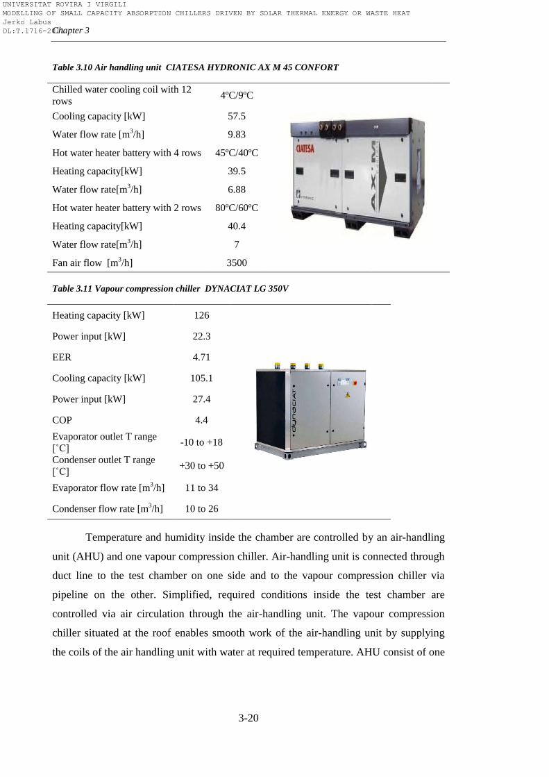
Chapter 3
3-20
Table 3.10 Air handling unit CIATESA HYDRONIC AX M 45 CONFORT
Chilled water cooling coil with 12
rows 4ºC/9ºC
Cooling capacity [kW] 57.5
Water flow rate [m3/h] 9.83
Hot water heater battery with 4 rows 45ºC/40ºC
Heating capacity[kW] 39.5
Water flow rate[m3/h] 6.88
Hot water heater battery with 2 rows 80ºC/60ºC
Heating capacity[kW] 40.4
Water flow rate[m3/h] 7
Fan air flow [m3/h] 3500
Table 3.11 Vapour compression chiller DYNACIAT LG 350V
Heating capacity [kW] 126
Power input [kW] 22.3
EER 4.71
Cooling capacity [kW] 105.1
Power input [kW] 27.4
COP 4.4
Evaporator outlet T range
[˚C] -10 to +18
Condenser outlet T range
[˚C] +30 to +50
Evaporator flow rate [m3/h] 11 to 34
Condenser flow rate [m3/h] 10 to 26
Temperature and humidity inside the chamber are controlled by an air-handling
unit (AHU) and one vapour compression chiller. Air-handling unit is connected through
duct line to the test chamber on one side and to the vapour compression chiller via
pipeline on the other. Simplified, required conditions inside the test chamber are
controlled via air circulation through the air-handling unit. The vapour compression
chiller situated at the roof enables smooth work of the air-handling unit by supplying
the coils of the air handling unit with water at required temperature. AHU consist of one
UNIVERSITAT ROVIRA I VIRGILI MODELLING OF SMALL CAPACITY ABSORPTION CHILLERS DRIVEN BY SOLAR THERMAL ENERGY OR WASTE HEAT Jerko Labus DL:T.1716-2011
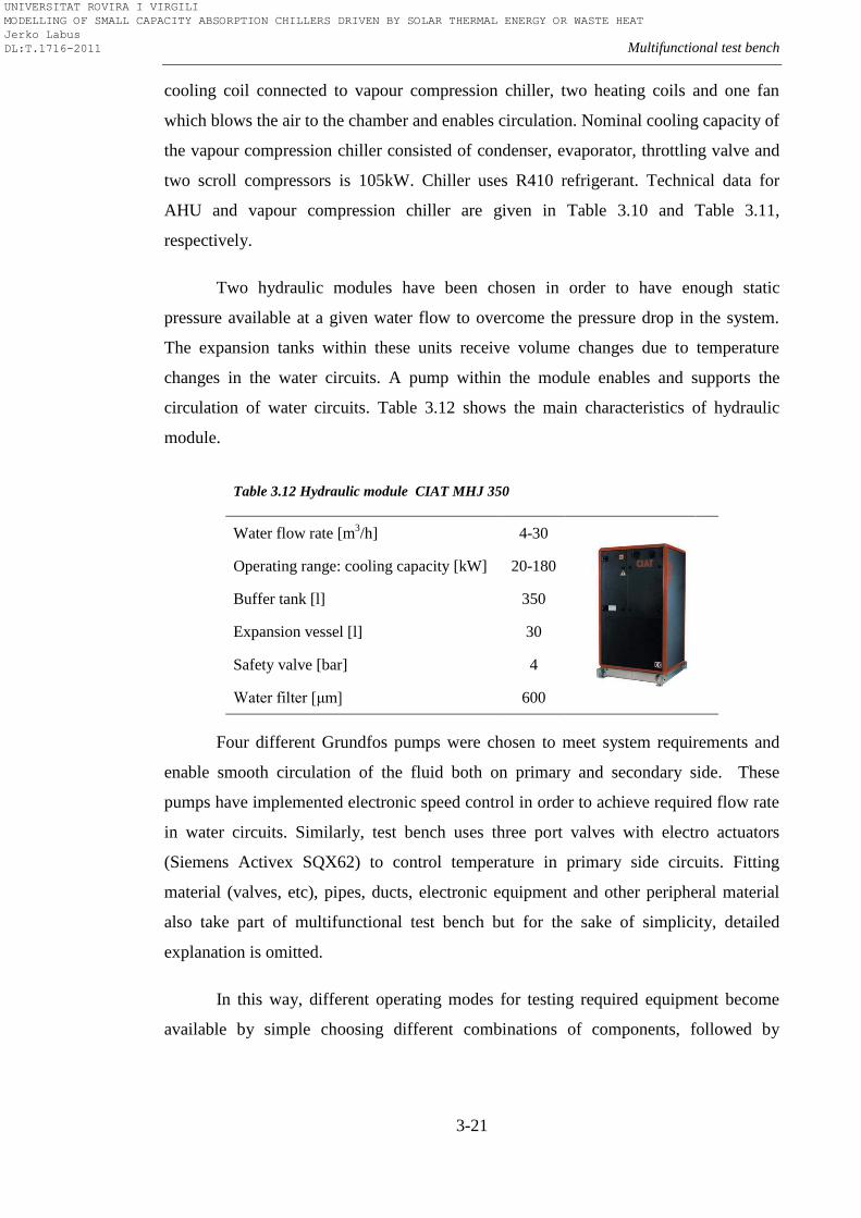
Multifunctional test bench
3-21
cooling coil connected to vapour compression chiller, two heating coils and one fan
which blows the air to the chamber and enables circulation. Nominal cooling capacity of
the vapour compression chiller consisted of condenser, evaporator, throttling valve and
two scroll compressors is 105kW. Chiller uses R410 refrigerant. Technical data for
AHU and vapour compression chiller are given in Table 3.10 and Table 3.11,
respectively.
Two hydraulic modules have been chosen in order to have enough static
pressure available at a given water flow to overcome the pressure drop in the system.
The expansion tanks within these units receive volume changes due to temperature
changes in the water circuits. A pump within the module enables and supports the
circulation of water circuits. Table 3.12 shows the main characteristics of hydraulic
module.
Table 3.12 Hydraulic module CIAT MHJ 350
Water flow rate [m3/h] 4-30
Operating range: cooling capacity [kW] 20-180
Buffer tank [l] 350
Expansion vessel [l] 30
Safety valve [bar] 4
Water filter [μm] 600
Four different Grundfos pumps were chosen to meet system requirements and
enable smooth circulation of the fluid both on primary and secondary side. These
pumps have implemented electronic speed control in order to achieve required flow rate
in water circuits. Similarly, test bench uses three port valves with electro actuators
(Siemens Activex SQX62) to control temperature in primary side circuits. Fitting
material (valves, etc), pipes, ducts, electronic equipment and other peripheral material
also take part of multifunctional test bench but for the sake of simplicity, detailed
explanation is omitted.
In this way, different operating modes for testing required equipment become
available by simple choosing different combinations of components, followed by
UNIVERSITAT ROVIRA I VIRGILI MODELLING OF SMALL CAPACITY ABSORPTION CHILLERS DRIVEN BY SOLAR THERMAL ENERGY OR WASTE HEAT Jerko Labus DL:T.1716-2011
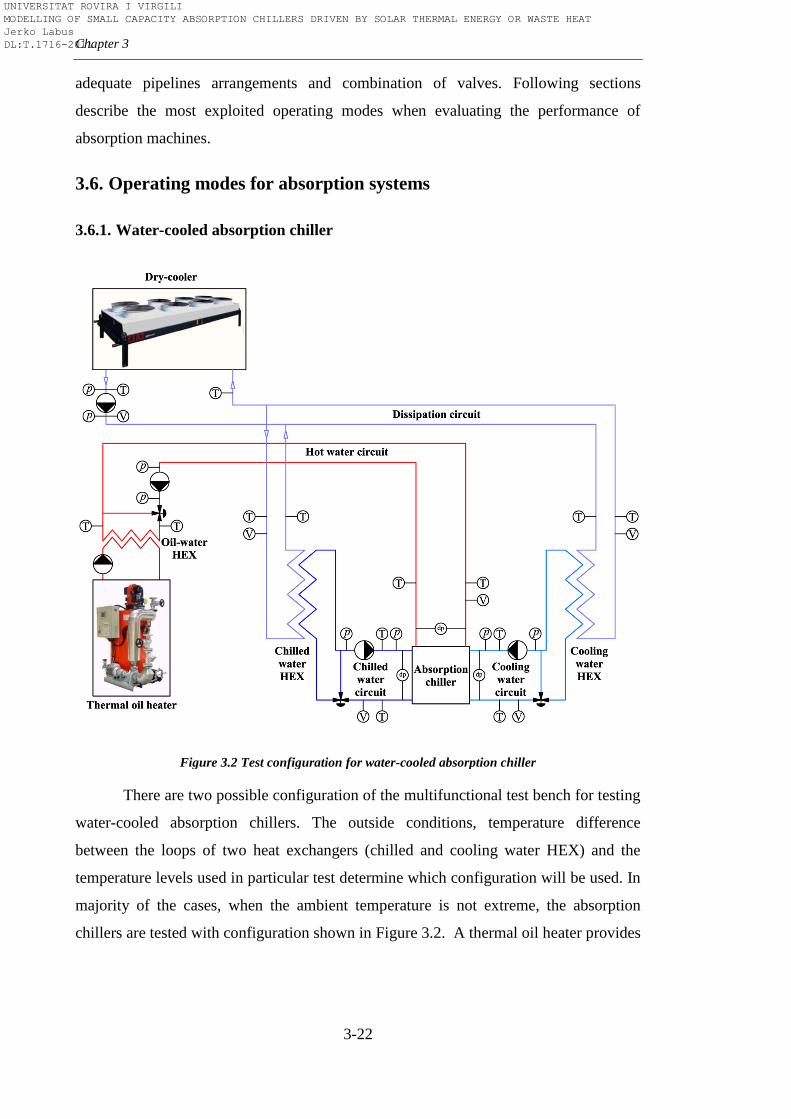
Chapter 3
3-22
adequate pipelines arrangements and combination of valves. Following sections
describe the most exploited operating modes when evaluating the performance of
absorption machines.
3.6. Operating modes for absorption systems
3.6.1. Water-cooled absorption chiller
Figure 3.2 Test configuration for water-cooled absorption chiller
There are two possible configuration of the multifunctional test bench for testing
water-cooled absorption chillers. The outside conditions, temperature difference
between the loops of two heat exchangers (chilled and cooling water HEX) and the
temperature levels used in particular test determine which configuration will be used. In
majority of the cases, when the ambient temperature is not extreme, the absorption
chillers are tested with configuration shown in Figure 3.2. A thermal oil heater provides
UNIVERSITAT ROVIRA I VIRGILI MODELLING OF SMALL CAPACITY ABSORPTION CHILLERS DRIVEN BY SOLAR THERMAL ENERGY OR WASTE HEAT Jerko Labus DL:T.1716-2011
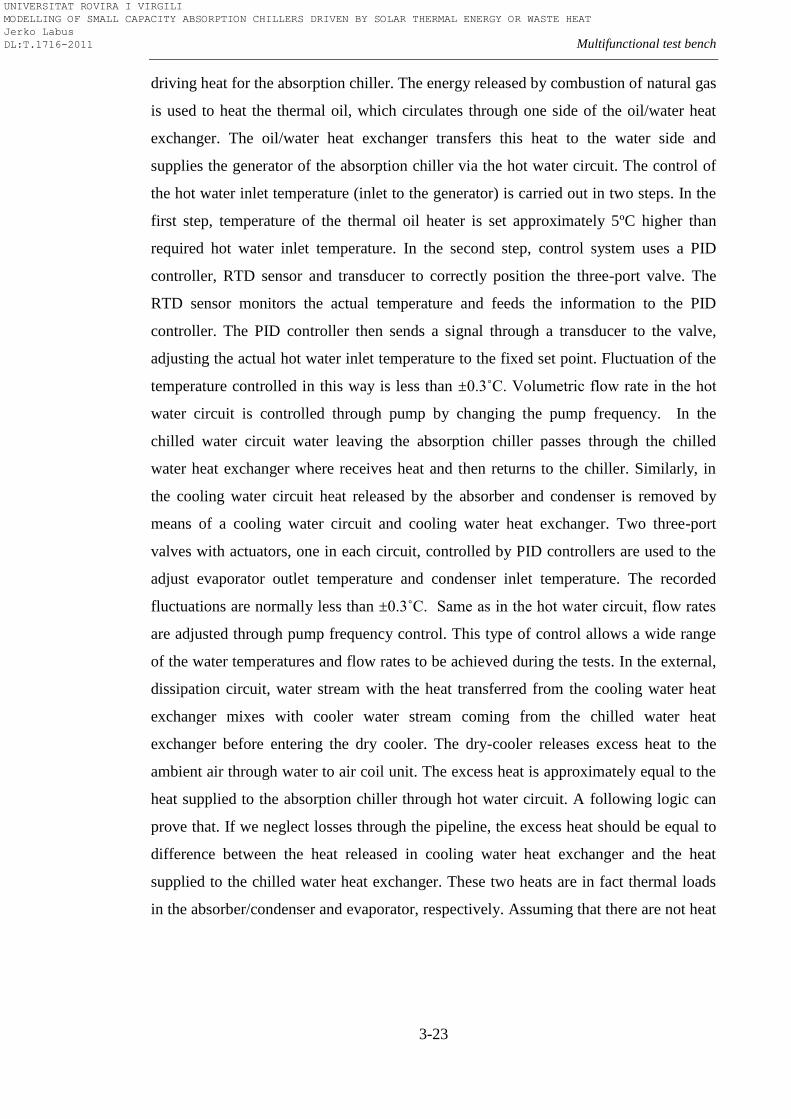
Multifunctional test bench
3-23
driving heat for the absorption chiller. The energy released by combustion of natural gas
is used to heat the thermal oil, which circulates through one side of the oil/water heat
exchanger. The oil/water heat exchanger transfers this heat to the water side and
supplies the generator of the absorption chiller via the hot water circuit. The control of
the hot water inlet temperature (inlet to the generator) is carried out in two steps. In the
first step, temperature of the thermal oil heater is set approximately 5ºC higher than
required hot water inlet temperature. In the second step, control system uses a PID
controller, RTD sensor and transducer to correctly position the three-port valve. The
RTD sensor monitors the actual temperature and feeds the information to the PID
controller. The PID controller then sends a signal through a transducer to the valve,
adjusting the actual hot water inlet temperature to the fixed set point. Fluctuation of the
temperature controlled in this way is less than ±0.3˚C. Volumetric flow rate in the hot
water circuit is controlled through pump by changing the pump frequency. In the
chilled water circuit water leaving the absorption chiller passes through the chilled
water heat exchanger where receives heat and then returns to the chiller. Similarly, in
the cooling water circuit heat released by the absorber and condenser is removed by
means of a cooling water circuit and cooling water heat exchanger. Two three-port
valves with actuators, one in each circuit, controlled by PID controllers are used to the
adjust evaporator outlet temperature and condenser inlet temperature. The recorded
fluctuations are normally less than ±0.3˚C. Same as in the hot water circuit, flow rates
are adjusted through pump frequency control. This type of control allows a wide range
of the water temperatures and flow rates to be achieved during the tests. In the external,
dissipation circuit, water stream with the heat transferred from the cooling water heat
exchanger mixes with cooler water stream coming from the chilled water heat
exchanger before entering the dry cooler. The dry-cooler releases excess heat to the
ambient air through water to air coil unit. The excess heat is approximately equal to the
heat supplied to the absorption chiller through hot water circuit. A following logic can
prove that. If we neglect losses through the pipeline, the excess heat should be equal to
difference between the heat released in cooling water heat exchanger and the heat
supplied to the chilled water heat exchanger. These two heats are in fact thermal loads
in the absorber/condenser and evaporator, respectively. Assuming that there are not heat
UNIVERSITAT ROVIRA I VIRGILI MODELLING OF SMALL CAPACITY ABSORPTION CHILLERS DRIVEN BY SOLAR THERMAL ENERGY OR WASTE HEAT Jerko Labus DL:T.1716-2011
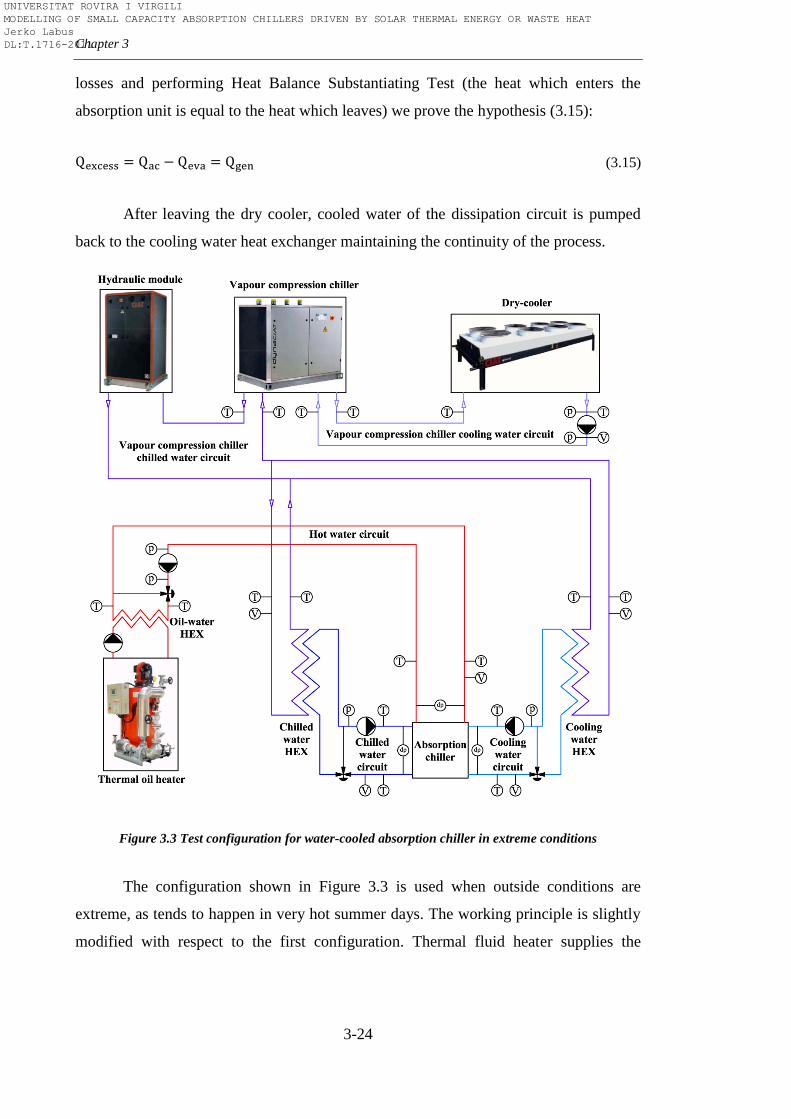
Chapter 3
3-24
losses and performing Heat Balance Substantiating Test (the heat which enters the
absorption unit is equal to the heat which leaves) we prove the hypothesis (3.15):
(3.15)
After leaving the dry cooler, cooled water of the dissipation circuit is pumped
back to the cooling water heat exchanger maintaining the continuity of the process.
Figure 3.3 Test configuration for water-cooled absorption chiller in extreme conditions
The configuration shown in Figure 3.3 is used when outside conditions are
extreme, as tends to happen in very hot summer days. The working principle is slightly
modified with respect to the first configuration. Thermal fluid heater supplies the
UNIVERSITAT ROVIRA I VIRGILI MODELLING OF SMALL CAPACITY ABSORPTION CHILLERS DRIVEN BY SOLAR THERMAL ENERGY OR WASTE HEAT Jerko Labus DL:T.1716-2011
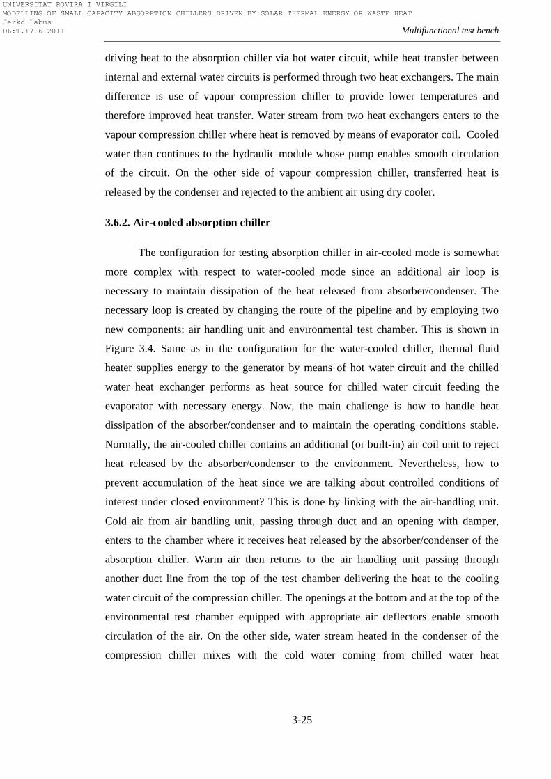
Multifunctional test bench
3-25
driving heat to the absorption chiller via hot water circuit, while heat transfer between
internal and external water circuits is performed through two heat exchangers. The main
difference is use of vapour compression chiller to provide lower temperatures and
therefore improved heat transfer. Water stream from two heat exchangers enters to the
vapour compression chiller where heat is removed by means of evaporator coil. Cooled
water than continues to the hydraulic module whose pump enables smooth circulation
of the circuit. On the other side of vapour compression chiller, transferred heat is
released by the condenser and rejected to the ambient air using dry cooler.
3.6.2. Air-cooled absorption chiller
The configuration for testing absorption chiller in air-cooled mode is somewhat
more complex with respect to water-cooled mode since an additional air loop is
necessary to maintain dissipation of the heat released from absorber/condenser. The
necessary loop is created by changing the route of the pipeline and by employing two
new components: air handling unit and environmental test chamber. This is shown in
Figure 3.4. Same as in the configuration for the water-cooled chiller, thermal fluid
heater supplies energy to the generator by means of hot water circuit and the chilled
water heat exchanger performs as heat source for chilled water circuit feeding the
evaporator with necessary energy. Now, the main challenge is how to handle heat
dissipation of the absorber/condenser and to maintain the operating conditions stable.
Normally, the air-cooled chiller contains an additional (or built-in) air coil unit to reject
heat released by the absorber/condenser to the environment. Nevertheless, how to
prevent accumulation of the heat since we are talking about controlled conditions of
interest under closed environment? This is done by linking with the air-handling unit.
Cold air from air handling unit, passing through duct and an opening with damper,
enters to the chamber where it receives heat released by the absorber/condenser of the
absorption chiller. Warm air then returns to the air handling unit passing through
another duct line from the top of the test chamber delivering the heat to the cooling
water circuit of the compression chiller. The openings at the bottom and at the top of the
environmental test chamber equipped with appropriate air deflectors enable smooth
circulation of the air. On the other side, water stream heated in the condenser of the
compression chiller mixes with the cold water coming from chilled water heat
UNIVERSITAT ROVIRA I VIRGILI MODELLING OF SMALL CAPACITY ABSORPTION CHILLERS DRIVEN BY SOLAR THERMAL ENERGY OR WASTE HEAT Jerko Labus DL:T.1716-2011
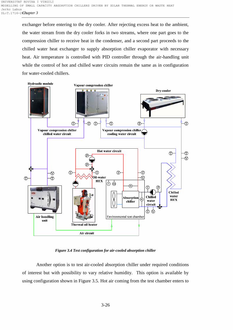
Chapter 3
3-26
exchanger before entering to the dry cooler. After rejecting excess heat to the ambient,
the water stream from the dry cooler forks in two streams, where one part goes to the
compression chiller to receive heat in the condenser, and a second part proceeds to the
chilled water heat exchanger to supply absorption chiller evaporator with necessary
heat. Air temperature is controlled with PID controller through the air-handling unit
while the control of hot and chilled water circuits remain the same as in configuration
for water-cooled chillers.
Figure 3.4 Test configuration for air-cooled absorption chiller
Another option is to test air-cooled absorption chiller under required conditions
of interest but with possibility to vary relative humidity. This option is available by
using configuration shown in Figure 3.5. Hot air coming from the test chamber enters to
UNIVERSITAT ROVIRA I VIRGILI MODELLING OF SMALL CAPACITY ABSORPTION CHILLERS DRIVEN BY SOLAR THERMAL ENERGY OR WASTE HEAT Jerko Labus DL:T.1716-2011
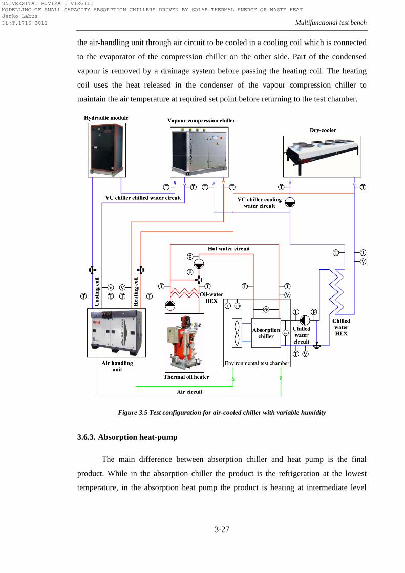
Multifunctional test bench
3-27
the air-handling unit through air circuit to be cooled in a cooling coil which is connected
to the evaporator of the compression chiller on the other side. Part of the condensed
vapour is removed by a drainage system before passing the heating coil. The heating
coil uses the heat released in the condenser of the vapour compression chiller to
maintain the air temperature at required set point before returning to the test chamber.
Figure 3.5 Test configuration for air-cooled chiller with variable humidity
3.6.3. Absorption heat-pump
The main difference between absorption chiller and heat pump is the final
product. While in the absorption chiller the product is the refrigeration at the lowest
temperature, in the absorption heat pump the product is heating at intermediate level
UNIVERSITAT ROVIRA I VIRGILI MODELLING OF SMALL CAPACITY ABSORPTION CHILLERS DRIVEN BY SOLAR THERMAL ENERGY OR WASTE HEAT Jerko Labus DL:T.1716-2011
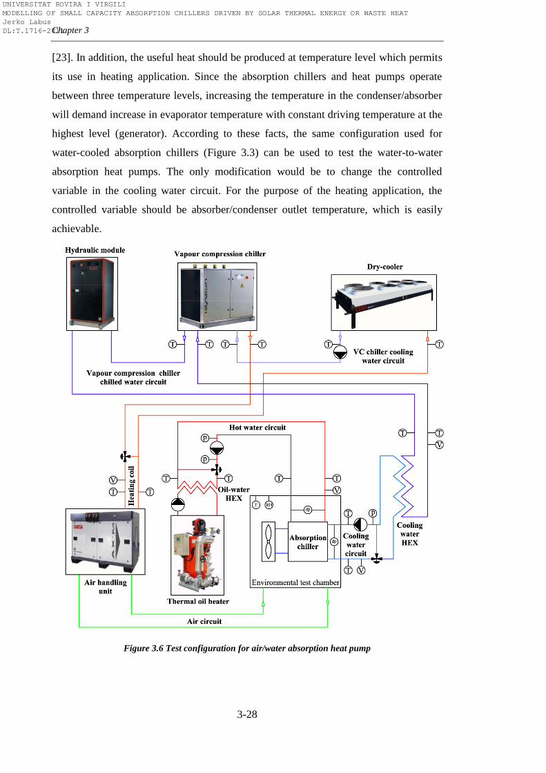
Chapter 3
3-28
[23]. In addition, the useful heat should be produced at temperature level which permits
its use in heating application. Since the absorption chillers and heat pumps operate
between three temperature levels, increasing the temperature in the condenser/absorber
will demand increase in evaporator temperature with constant driving temperature at the
highest level (generator). According to these facts, the same configuration used for
water-cooled absorption chillers (Figure 3.3) can be used to test the water-to-water
absorption heat pumps. The only modification would be to change the controlled
variable in the cooling water circuit. For the purpose of the heating application, the
controlled variable should be absorber/condenser outlet temperature, which is easily
achievable.
Figure 3.6 Test configuration for air/water absorption heat pump
UNIVERSITAT ROVIRA I VIRGILI MODELLING OF SMALL CAPACITY ABSORPTION CHILLERS DRIVEN BY SOLAR THERMAL ENERGY OR WASTE HEAT Jerko Labus DL:T.1716-2011
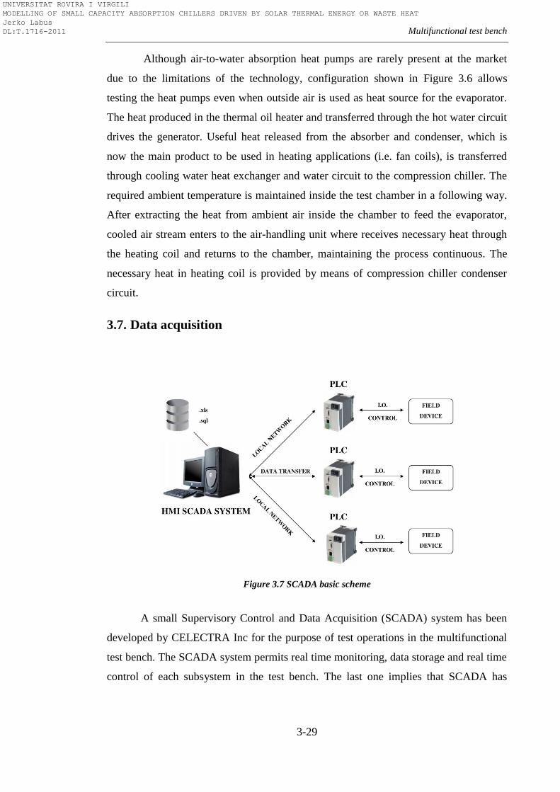
Multifunctional test bench
3-29
Although air-to-water absorption heat pumps are rarely present at the market
due to the limitations of the technology, configuration shown in Figure 3.6 allows
testing the heat pumps even when outside air is used as heat source for the evaporator.
The heat produced in the thermal oil heater and transferred through the hot water circuit
drives the generator. Useful heat released from the absorber and condenser, which is
now the main product to be used in heating applications (i.e. fan coils), is transferred
through cooling water heat exchanger and water circuit to the compression chiller. The
required ambient temperature is maintained inside the test chamber in a following way.
After extracting the heat from ambient air inside the chamber to feed the evaporator,
cooled air stream enters to the air-handling unit where receives necessary heat through
the heating coil and returns to the chamber, maintaining the process continuous. The
necessary heat in heating coil is provided by means of compression chiller condenser
circuit.
3.7. Data acquisition
Figure 3.7 SCADA basic scheme
A small Supervisory Control and Data Acquisition (SCADA) system has been
developed by CELECTRA Inc for the purpose of test operations in the multifunctional
test bench. The SCADA system permits real time monitoring, data storage and real time
control of each subsystem in the test bench. The last one implies that SCADA has
UNIVERSITAT ROVIRA I VIRGILI MODELLING OF SMALL CAPACITY ABSORPTION CHILLERS DRIVEN BY SOLAR THERMAL ENERGY OR WASTE HEAT Jerko Labus DL:T.1716-2011
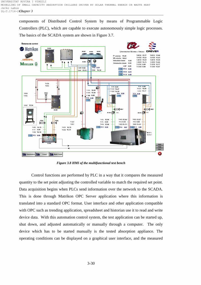
Chapter 3
3-30
components of Distributed Control System by means of Programmable Logic
Controllers (PLC), which are capable to execute autonomously simple logic processes.
The basics of the SCADA system are shown in Figure 3.7.
Figure 3.8 HMI of the multifunctional test bench
Control functions are performed by PLC in a way that it compares the measured
quantity to the set point adjusting the controlled variable to match the required set point.
Data acquisition begins when PLCs send information over the network to the SCADA.
This is done through Matrikon OPC Server application where this information is
translated into a standard OPC format. User interface and other application compatible
with OPC such as trending application, spreadsheet and historian use it to read and write
device data. With this automation control system, the test application can be started up,
shut down, and adjusted automatically or manually through a computer. The only
device which has to be started manually is the tested absorption appliance. The
operating conditions can be displayed on a graphical user interface, and the measured
UNIVERSITAT ROVIRA I VIRGILI MODELLING OF SMALL CAPACITY ABSORPTION CHILLERS DRIVEN BY SOLAR THERMAL ENERGY OR WASTE HEAT Jerko Labus DL:T.1716-2011
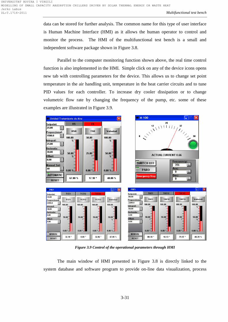
Multifunctional test bench
3-31
data can be stored for further analysis. The common name for this type of user interface
is Human Machine Interface (HMI) as it allows the human operator to control and
monitor the process. The HMI of the multifunctional test bench is a small and
independent software package shown in Figure 3.8.
Parallel to the computer monitoring function shown above, the real time control
function is also implemented in the HMI. Simple click on any of the device icons opens
new tab with controlling parameters for the device. This allows us to change set point
temperature in the air handling unit, temperature in the heat carrier circuits and to tune
PID values for each controller. To increase dry cooler dissipation or to change
volumetric flow rate by changing the frequency of the pump, etc. some of these
examples are illustrated in Figure 3.9.
Figure 3.9 Control of the operational parameters through HMI
The main window of HMI presented in Figure 3.8 is directly linked to the
system database and software program to provide on-line data visualization, process
UNIVERSITAT ROVIRA I VIRGILI MODELLING OF SMALL CAPACITY ABSORPTION CHILLERS DRIVEN BY SOLAR THERMAL ENERGY OR WASTE HEAT Jerko Labus DL:T.1716-2011
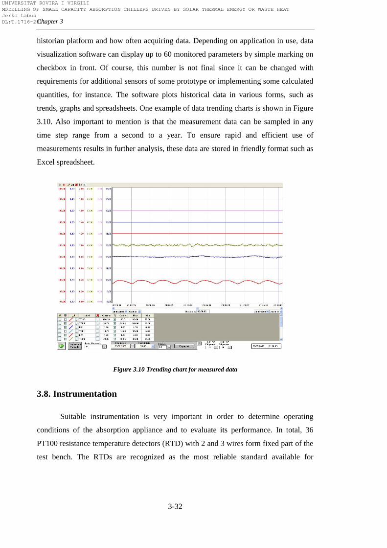
Chapter 3
3-32
historian platform and how often acquiring data. Depending on application in use, data
visualization software can display up to 60 monitored parameters by simple marking on
checkbox in front. Of course, this number is not final since it can be changed with
requirements for additional sensors of some prototype or implementing some calculated
quantities, for instance. The software plots historical data in various forms, such as
trends, graphs and spreadsheets. One example of data trending charts is shown in Figure
3.10. Also important to mention is that the measurement data can be sampled in any
time step range from a second to a year. To ensure rapid and efficient use of
measurements results in further analysis, these data are stored in friendly format such as
Excel spreadsheet.
Figure 3.10 Trending chart for measured data
3.8. Instrumentation
Suitable instrumentation is very important in order to determine operating
conditions of the absorption appliance and to evaluate its performance. In total, 36
PT100 resistance temperature detectors (RTD) with 2 and 3 wires form fixed part of the
test bench. The RTDs are recognized as the most reliable standard available for
UNIVERSITAT ROVIRA I VIRGILI MODELLING OF SMALL CAPACITY ABSORPTION CHILLERS DRIVEN BY SOLAR THERMAL ENERGY OR WASTE HEAT Jerko Labus DL:T.1716-2011
Multifunctional test bench
3-33
temperature measurement, more accurate than thermocouples and more suitable than
thermistors for this kind of test application. All temperature sensors were chosen and
installed according to recommended ASHRAE normative [113]. PT100 Class A comes
with manufacturer accuracy of ±0.1ºC at zero ºC. The nominal resistance of a RTD is
100Ω at zero ºC. Equation 3.16 describes a nonlinear relationship between temperature
and resistance:
(3.16)
where:
A=3.9083 10-3
B=-5.775 10-7
C=-4.183 10-12
below 0ºC, zero above 0ºC
Three Khrone Optiflux 1300 electromagnetic flowmeters are installed to
measure the volumetric flow rate in the heat carrier water circuits of the tested
absorption appliance. Electromagnetic flowmeters are the guarantee to measure the flow
rate without disturbing the test bench operation. Beside these three, the test bench also
has five ABB FXE4000-DE43F flowmeters placed in secondary circuits for monitoring
all the flows within the facility. Both models have an accuracy of 0.5% of measured
flow and both comply with ASME Standard MFC-16M-1995 [114]. An outdoor
relative humidity sensor measures relative humidity inside the environmental test
chamber and more than 20 pressure gauges mounted all over the test bench to ensure
safe operation. To measure the outside conditions test facility consist of two devices
placed at the roof of the laboratory building. For precise air humidity and temperature
measurements, Siemens QFA3171+ AQF3100 outdoor relative humidity and
temperature sensor is used. An anemometer and a vane, which form Young Wind
Sentry Set, are used to measure the wind speed and wind direction.
Beside described instrumentation, some devices, which are not an integral part
of the multifunctional test bench, can be mounted depending on type of the experiment
performed. For instance, in experiments with absorption machines is always good to
UNIVERSITAT ROVIRA I VIRGILI MODELLING OF SMALL CAPACITY ABSORPTION CHILLERS DRIVEN BY SOLAR THERMAL ENERGY OR WASTE HEAT Jerko Labus DL:T.1716-2011
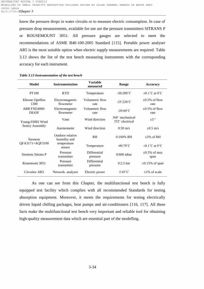
Chapter 3
3-34
know the pressure drops in water circuits or to measure electric consumption. In case of
pressure drop measurements, available for use are the pressure transmitters SITRANS P
or ROUSEMOUNT 3051. All pressure gauges are selected to meet the
recommendations of ASME B40-100-2005 Standard [115]. Portable power analyser
AR5 is the most suitable option when electric supply measurements are required. Table
3.13 shows the list of the test bench measuring instruments with the corresponding
accuracy for each instrument.
Table 3.13 Instrumentation of the test bench
Model Instrumentation Variable
measured Range Accuracy
PT100 RTD Temperature -50:200˚C ±0.1˚C at 0˚C
Khrone Optiflux
1300
Electromagnetic
flowmeter
Volumetric flow
rate -25:220˚C
±0.5% of flow
rate
ABB FXE4000-
DE43F
Electromagnetic
flowmeter
Volumetric flow
rate -20:60˚C
±0.5% of flow
rate
Young 03002 Wind
Sentry Assembly
Vane Wind direction 360˚ mechanical
352˚ electrical ±5 º
Anemometer Wind direction 0:50 m/s ±0.5 m/s
Siemens
QFA3171+AQF3100
Outdoor relative
humidity and
temperature
sensor
RH 0:100% RH ±2% of RH
Temperature -40:70˚C ±0.1˚C at 0˚C
Siemens Sitrans P Pressure
transmitter
Differential
pressure 0:600 mbar
±0.5% of max
span
Rosemount 3051 Pressure
transmitter
Differential
pressure 0:2.5 bar ±0.15% of span
Circuitor AR5 Network analyzer Electric power 5:45˚C ±1% of scale
As one can see from this Chapter, the multifunctional test bench is fully
equipped test facility which complies with all recommended Standards for testing
absorption equipment. Moreover, it meets the requirements for testing electrically
driven liquid chilling packages, heat pumps and air-conditioners [116, 117]. All these
facts make the multifunctional test bench very important and reliable tool for obtaining
high-quality measurement data which are essential part of the modelling.
UNIVERSITAT ROVIRA I VIRGILI MODELLING OF SMALL CAPACITY ABSORPTION CHILLERS DRIVEN BY SOLAR THERMAL ENERGY OR WASTE HEAT Jerko Labus DL:T.1716-2011
4-1
Chapter 4
Testing the performance of absorption chillers
“There is no such thing as a failed experiment,
only experiments with unexpected outcomes”
Richard Buckminster Fuller
4.1. Introduction
Large-scale absorption air-conditioning and refrigeration equipment have been
present on the market for a long time, while the development of small-scale absorption
chillers and heat pumps has intensified in the last decades which was triggered by rising
concern about climatic change as well as with recent developments and progress in the
field of solar energy and waste heat usage. This equipment has entered in early stage of
standard production, designed for residential, commercial and industrial application.
However, it is still in infancy and a lot of research efforts have to be made to be
competitive with conventional systems. Therefore, experimental work is very important
issue in order to improve this technology. Moreover, performance evaluation of the
complete operating range is preferable for different application purposes. Most of the
information are not available or are very scarce, especially when talking about
commercial equipment. Despite the fact that the experimental work with the absorption
machines is essential, there are just a few guidelines, standards and other expert
recommendations. There is almost no standard procedure on how to test commercial
(pilot either) absorption equipment just like there is no unique data treatment and
analysis. Just to avoid misinterpretation, there are couple of standards about absorption
appliances mentioned in previous Chapter, but there are mainly referring to standard
rating conditions. Actually, one of the current objectives of IEA Annex 34 is to provide
an unified basis for the development and revision of the standardisation framework to
help thermally driven technologies to consolidate and further develop their market
position [118]. Depending on end-user and purpose, scarce information is not enough.
This fact is particularly expressed in the fields of simulation and control. Without
UNIVERSITAT ROVIRA I VIRGILI MODELLING OF SMALL CAPACITY ABSORPTION CHILLERS DRIVEN BY SOLAR THERMAL ENERGY OR WASTE HEAT Jerko Labus DL:T.1716-2011
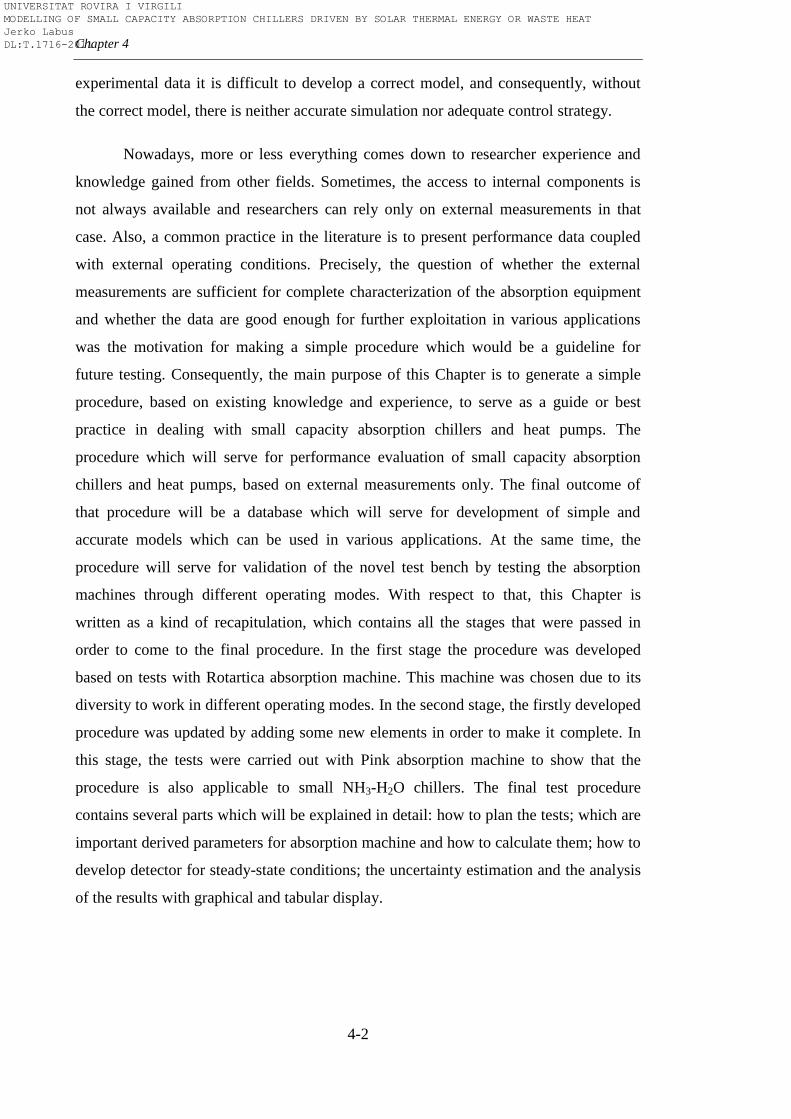
Chapter 4
4-2
experimental data it is difficult to develop a correct model, and consequently, without
the correct model, there is neither accurate simulation nor adequate control strategy.
Nowadays, more or less everything comes down to researcher experience and
knowledge gained from other fields. Sometimes, the access to internal components is
not always available and researchers can rely only on external measurements in that
case. Also, a common practice in the literature is to present performance data coupled
with external operating conditions. Precisely, the question of whether the external
measurements are sufficient for complete characterization of the absorption equipment
and whether the data are good enough for further exploitation in various applications
was the motivation for making a simple procedure which would be a guideline for
future testing. Consequently, the main purpose of this Chapter is to generate a simple
procedure, based on existing knowledge and experience, to serve as a guide or best
practice in dealing with small capacity absorption chillers and heat pumps. The
procedure which will serve for performance evaluation of small capacity absorption
chillers and heat pumps, based on external measurements only. The final outcome of
that procedure will be a database which will serve for development of simple and
accurate models which can be used in various applications. At the same time, the
procedure will serve for validation of the novel test bench by testing the absorption
machines through different operating modes. With respect to that, this Chapter is
written as a kind of recapitulation, which contains all the stages that were passed in
order to come to the final procedure. In the first stage the procedure was developed
based on tests with Rotartica absorption machine. This machine was chosen due to its
diversity to work in different operating modes. In the second stage, the firstly developed
procedure was updated by adding some new elements in order to make it complete. In
this stage, the tests were carried out with Pink absorption machine to show that the
procedure is also applicable to small NH3-H2O chillers. The final test procedure
contains several parts which will be explained in detail: how to plan the tests; which are
important derived parameters for absorption machine and how to calculate them; how to
develop detector for steady-state conditions; the uncertainty estimation and the analysis
of the results with graphical and tabular display.
UNIVERSITAT ROVIRA I VIRGILI MODELLING OF SMALL CAPACITY ABSORPTION CHILLERS DRIVEN BY SOLAR THERMAL ENERGY OR WASTE HEAT Jerko Labus DL:T.1716-2011
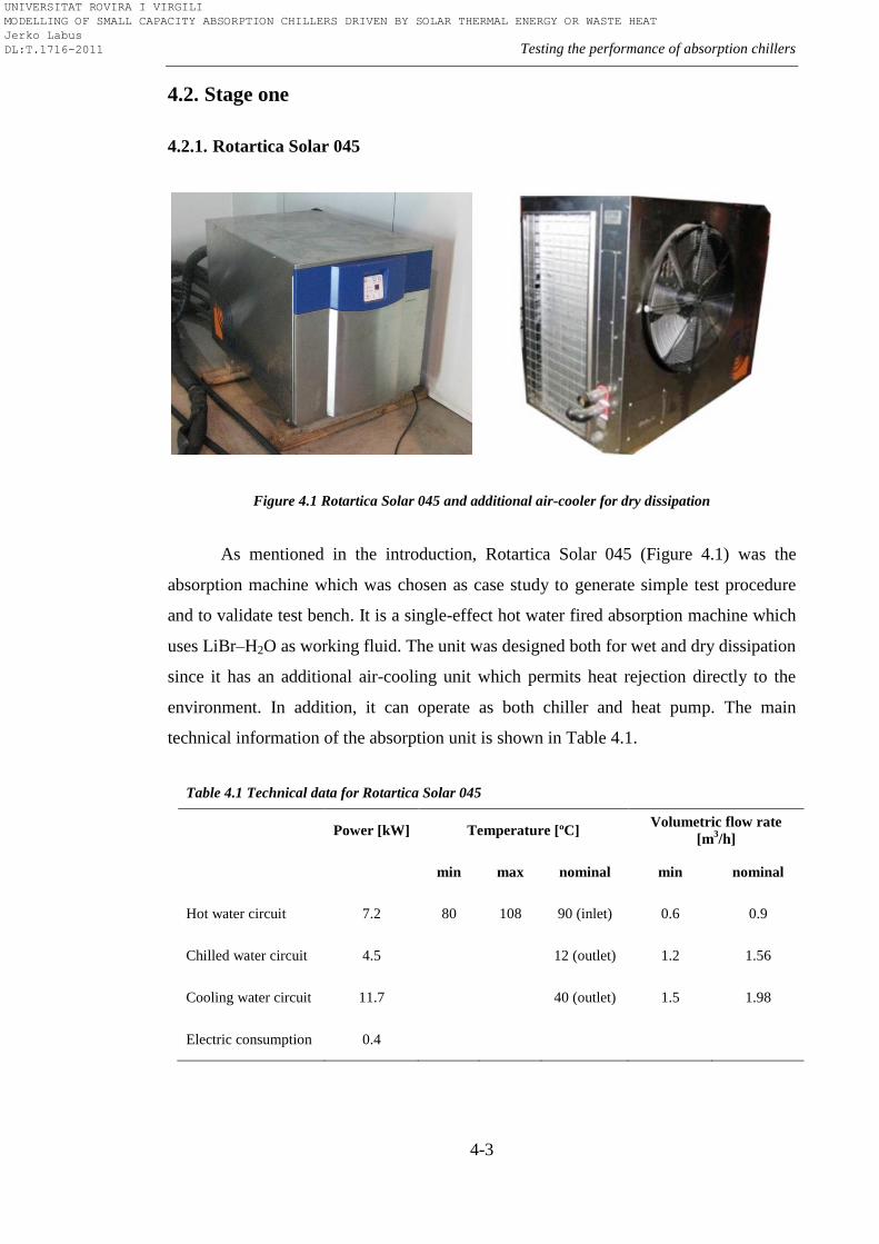
Testing the performance of absorption chillers
4-3
4.2. Stage one
4.2.1. Rotartica Solar 045
Figure 4.1 Rotartica Solar 045 and additional air-cooler for dry dissipation
As mentioned in the introduction, Rotartica Solar 045 (Figure 4.1) was the
absorption machine which was chosen as case study to generate simple test procedure
and to validate test bench. It is a single-effect hot water fired absorption machine which
uses LiBr–H2O as working fluid. The unit was designed both for wet and dry dissipation
since it has an additional air-cooling unit which permits heat rejection directly to the
environment. In addition, it can operate as both chiller and heat pump. The main
technical information of the absorption unit is shown in Table 4.1.
Table 4.1 Technical data for Rotartica Solar 045
Power [kW] Temperature [ºC] Volumetric flow rate
[m3/h]
min max nominal min nominal
Hot water circuit 7.2 80 108 90 (inlet) 0.6 0.9
Chilled water circuit 4.5 12 (outlet) 1.2 1.56
Cooling water circuit 11.7 40 (outlet) 1.5 1.98
Electric consumption 0.4
UNIVERSITAT ROVIRA I VIRGILI MODELLING OF SMALL CAPACITY ABSORPTION CHILLERS DRIVEN BY SOLAR THERMAL ENERGY OR WASTE HEAT Jerko Labus DL:T.1716-2011
Chapter 4
4-4
The technological core of the machine is a rotary unit where all heat exchangers
are located inside a hermetically sealed drum while rotating at approximately 400
revolutions per minute. However, use of rotational forces in absorption technology is
not a new idea. In 1973, Pravda [119] patented a portable heat operated rotary heat
pump for use in air-conditioning, particularly for cooling the passenger compartments in
vehicles. It included a generator, absorber, condenser and evaporator, all mounted as a
group. In 1984, Kantor [120] presented invention to provide a rotary inertial
thermodynamic system and method in which the fluid flow is stable. One of the future
objectives of the invention was to provide such a system which would be relatively
compact, lightweight, uncomplicated, inexpensive and capable of operating under
variety of conditions and in different environments. Ramshaw and Winnington [121]
also presented an rotary assembly of absorption heat pump in which the vapour
generator, the condenser and the absorber each include a wall across which the volatile
component and liquid absorbent are flowing under the action of forces generated during
the rotation of the assembly. The disclosure of Pravda [122] comprised a plurality of
enclosed, interconnected components or chambers mounted for rotation in the rotary
absorption heat pump. The radiator and the condenser were located concentric with the
radial outboard of the absorber and absorber cooler and together with the generator
these elements formed a group which is airtight and liquid tight. In addition, the
disclosure was specially adapted to employ waste heat, radiator heat, solar heat or even
heat obtainable by burning low cost hydrocarbons or other fuels. A couple of years
later, the UK company Interotex Ltd. disclosed the patent of the double-effect
absorption machine based on rotational principle [123]. The absorption machine
comprised of a rotary assembly where all the components were interconnected to
provide cyclic flow paths for a volatile fluid and an absorbent fluid. This assembly
included a container associated with the flow paths of the volatile component for being
charged with the fluid, storing an excess amount of volatile fluid collecting upstream of
the evaporator exceeds a preset amount to adjust the concentrations of absorbent and
volatile fluid. One of the novelties of the disclosure was a scoop (Pitot) pump
arrangement for pumping and delivering it onto a surface of the evaporator. Finally, the
licence for this technology was bought by Spanish spin-off company Rotartica S.A.
UNIVERSITAT ROVIRA I VIRGILI MODELLING OF SMALL CAPACITY ABSORPTION CHILLERS DRIVEN BY SOLAR THERMAL ENERGY OR WASTE HEAT Jerko Labus DL:T.1716-2011
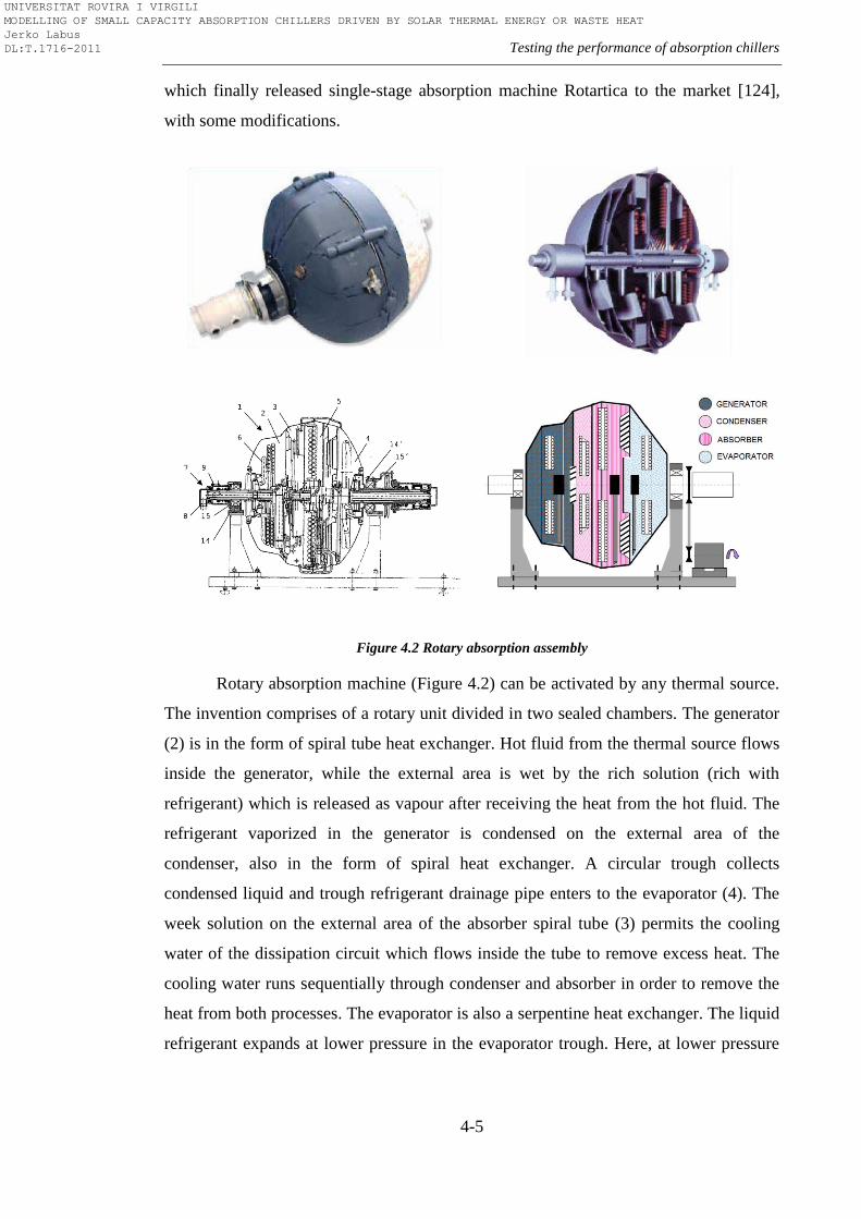
Testing the performance of absorption chillers
4-5
which finally released single-stage absorption machine Rotartica to the market [124],
with some modifications.
Figure 4.2 Rotary absorption assembly
Rotary absorption machine (Figure 4.2) can be activated by any thermal source.
The invention comprises of a rotary unit divided in two sealed chambers. The generator
(2) is in the form of spiral tube heat exchanger. Hot fluid from the thermal source flows
inside the generator, while the external area is wet by the rich solution (rich with
refrigerant) which is released as vapour after receiving the heat from the hot fluid. The
refrigerant vaporized in the generator is condensed on the external area of the
condenser, also in the form of spiral heat exchanger. A circular trough collects
condensed liquid and trough refrigerant drainage pipe enters to the evaporator (4). The
week solution on the external area of the absorber spiral tube (3) permits the cooling
water of the dissipation circuit which flows inside the tube to remove excess heat. The
cooling water runs sequentially through condenser and absorber in order to remove the
heat from both processes. The evaporator is also a serpentine heat exchanger. The liquid
refrigerant expands at lower pressure in the evaporator trough. Here, at lower pressure
UNIVERSITAT ROVIRA I VIRGILI MODELLING OF SMALL CAPACITY ABSORPTION CHILLERS DRIVEN BY SOLAR THERMAL ENERGY OR WASTE HEAT Jerko Labus DL:T.1716-2011
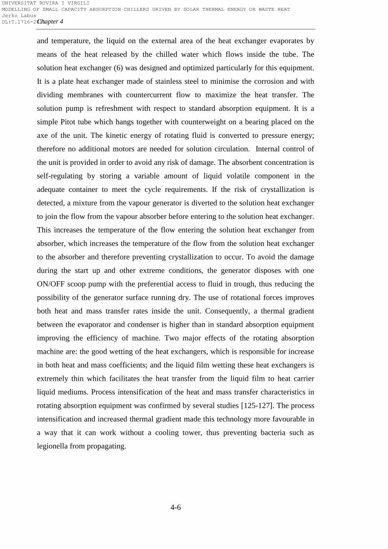
Chapter 4
4-6
and temperature, the liquid on the external area of the heat exchanger evaporates by
means of the heat released by the chilled water which flows inside the tube. The
solution heat exchanger (6) was designed and optimized particularly for this equipment.
It is a plate heat exchanger made of stainless steel to minimise the corrosion and with
dividing membranes with countercurrent flow to maximize the heat transfer. The
solution pump is refreshment with respect to standard absorption equipment. It is a
simple Pitot tube which hangs together with counterweight on a bearing placed on the
axe of the unit. The kinetic energy of rotating fluid is converted to pressure energy;
therefore no additional motors are needed for solution circulation. Internal control of
the unit is provided in order to avoid any risk of damage. The absorbent concentration is
self-regulating by storing a variable amount of liquid volatile component in the
adequate container to meet the cycle requirements. If the risk of crystallization is
detected, a mixture from the vapour generator is diverted to the solution heat exchanger
to join the flow from the vapour absorber before entering to the solution heat exchanger.
This increases the temperature of the flow entering the solution heat exchanger from
absorber, which increases the temperature of the flow from the solution heat exchanger
to the absorber and therefore preventing crystallization to occur. To avoid the damage
during the start up and other extreme conditions, the generator disposes with one
ON/OFF scoop pump with the preferential access to fluid in trough, thus reducing the
possibility of the generator surface running dry. The use of rotational forces improves
both heat and mass transfer rates inside the unit. Consequently, a thermal gradient
between the evaporator and condenser is higher than in standard absorption equipment
improving the efficiency of machine. Two major effects of the rotating absorption
machine are: the good wetting of the heat exchangers, which is responsible for increase
in both heat and mass coefficients; and the liquid film wetting these heat exchangers is
extremely thin which facilitates the heat transfer from the liquid film to heat carrier
liquid mediums. Process intensification of the heat and mass transfer characteristics in
rotating absorption equipment was confirmed by several studies [125-127]. The process
intensification and increased thermal gradient made this technology more favourable in
a way that it can work without a cooling tower, thus preventing bacteria such as
legionella from propagating.
UNIVERSITAT ROVIRA I VIRGILI MODELLING OF SMALL CAPACITY ABSORPTION CHILLERS DRIVEN BY SOLAR THERMAL ENERGY OR WASTE HEAT Jerko Labus DL:T.1716-2011
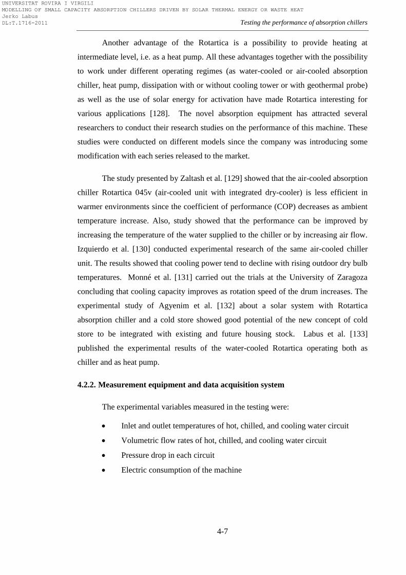
Testing the performance of absorption chillers
4-7
Another advantage of the Rotartica is a possibility to provide heating at
intermediate level, i.e. as a heat pump. All these advantages together with the possibility
to work under different operating regimes (as water-cooled or air-cooled absorption
chiller, heat pump, dissipation with or without cooling tower or with geothermal probe)
as well as the use of solar energy for activation have made Rotartica interesting for
various applications [128]. The novel absorption equipment has attracted several
researchers to conduct their research studies on the performance of this machine. These
studies were conducted on different models since the company was introducing some
modification with each series released to the market.
The study presented by Zaltash et al. [129] showed that the air-cooled absorption
chiller Rotartica 045v (air-cooled unit with integrated dry-cooler) is less efficient in
warmer environments since the coefficient of performance (COP) decreases as ambient
temperature increase. Also, study showed that the performance can be improved by
increasing the temperature of the water supplied to the chiller or by increasing air flow.
Izquierdo et al. [130] conducted experimental research of the same air-cooled chiller
unit. The results showed that cooling power tend to decline with rising outdoor dry bulb
temperatures. Monné et al. [131] carried out the trials at the University of Zaragoza
concluding that cooling capacity improves as rotation speed of the drum increases. The
experimental study of Agyenim et al. [132] about a solar system with Rotartica
absorption chiller and a cold store showed good potential of the new concept of cold
store to be integrated with existing and future housing stock. Labus et al. [133]
published the experimental results of the water-cooled Rotartica operating both as
chiller and as heat pump.
4.2.2. Measurement equipment and data acquisition system
The experimental variables measured in the testing were:
Inlet and outlet temperatures of hot, chilled, and cooling water circuit
Volumetric flow rates of hot, chilled, and cooling water circuit
Pressure drop in each circuit
Electric consumption of the machine
UNIVERSITAT ROVIRA I VIRGILI MODELLING OF SMALL CAPACITY ABSORPTION CHILLERS DRIVEN BY SOLAR THERMAL ENERGY OR WASTE HEAT Jerko Labus DL:T.1716-2011
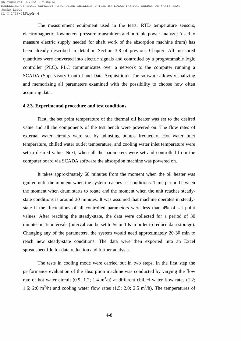
Chapter 4
4-8
The measurement equipment used in the tests: RTD temperature sensors,
electromagnetic flowmeters, pressure transmitters and portable power analyzer (used to
measure electric supply needed for shaft work of the absorption machine drum) has
been already described in detail in Section 3.8 of previous Chapter. All measured
quantities were converted into electric signals and controlled by a programmable logic
controller (PLC). PLC communicates over a network to the computer running a
SCADA (Supervisory Control and Data Acquisition). The software allows visualizing
and memorizing all parameters examined with the possibility to choose how often
acquiring data.
4.2.3. Experimental procedure and test conditions
First, the set point temperature of the thermal oil heater was set to the desired
value and all the components of the test bench were powered on. The flow rates of
external water circuits were set by adjusting pumps frequency. Hot water inlet
temperature, chilled water outlet temperature, and cooling water inlet temperature were
set to desired value. Next, when all the parameters were set and controlled from the
computer board via SCADA software the absorption machine was powered on.
It takes approximately 60 minutes from the moment when the oil heater was
ignited until the moment when the system reaches set conditions. Time period between
the moment when drum starts to rotate and the moment when the unit reaches steady-
state conditions is around 30 minutes. It was assumed that machine operates in steady-
state if the fluctuations of all controlled parameters were less than 4% of set point
values. After reaching the steady-state, the data were collected for a period of 30
minutes in 1s intervals (interval can be set to 5s or 10s in order to reduce data storage).
Changing any of the parameters, the system would need approximately 20-30 min to
reach new steady-state conditions. The data were then exported into an Excel
spreadsheet file for data reduction and further analysis.
The tests in cooling mode were carried out in two steps. In the first step the
performance evaluation of the absorption machine was conducted by varying the flow
rate of hot water circuit (0.9; 1.2; 1.4 m3/h) at different chilled water flow rates (1.2;
1.6; 2:0 m3/h) and cooling water flow rates (1.5; 2.0; 2.5 m
3/h). The temperatures of
UNIVERSITAT ROVIRA I VIRGILI MODELLING OF SMALL CAPACITY ABSORPTION CHILLERS DRIVEN BY SOLAR THERMAL ENERGY OR WASTE HEAT Jerko Labus DL:T.1716-2011
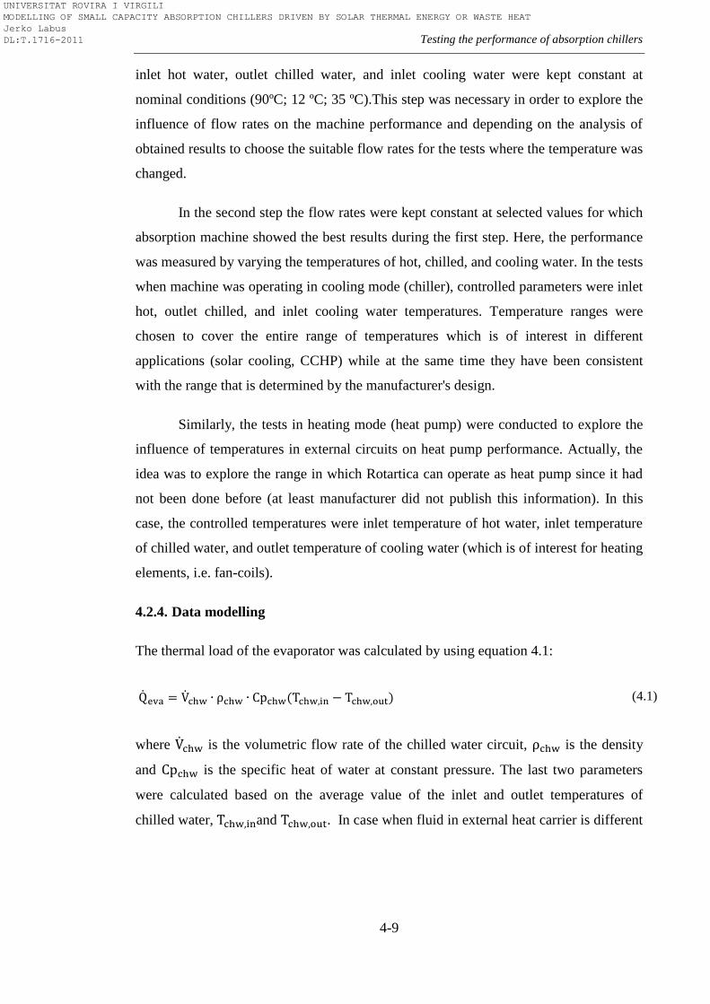
Testing the performance of absorption chillers
4-9
inlet hot water, outlet chilled water, and inlet cooling water were kept constant at
nominal conditions (90ºC; 12 ºC; 35 ºC).This step was necessary in order to explore the
influence of flow rates on the machine performance and depending on the analysis of
obtained results to choose the suitable flow rates for the tests where the temperature was
changed.
In the second step the flow rates were kept constant at selected values for which
absorption machine showed the best results during the first step. Here, the performance
was measured by varying the temperatures of hot, chilled, and cooling water. In the tests
when machine was operating in cooling mode (chiller), controlled parameters were inlet
hot, outlet chilled, and inlet cooling water temperatures. Temperature ranges were
chosen to cover the entire range of temperatures which is of interest in different
applications (solar cooling, CCHP) while at the same time they have been consistent
with the range that is determined by the manufacturer's design.
Similarly, the tests in heating mode (heat pump) were conducted to explore the
influence of temperatures in external circuits on heat pump performance. Actually, the
idea was to explore the range in which Rotartica can operate as heat pump since it had
not been done before (at least manufacturer did not publish this information). In this
case, the controlled temperatures were inlet temperature of hot water, inlet temperature
of chilled water, and outlet temperature of cooling water (which is of interest for heating
elements, i.e. fan-coils).
4.2.4. Data modelling
The thermal load of the evaporator was calculated by using equation 4.1:
(4.1)
where is the volumetric flow rate of the chilled water circuit, is the density
and is the specific heat of water at constant pressure. The last two parameters
were calculated based on the average value of the inlet and outlet temperatures of
chilled water, and . In case when fluid in external heat carrier is different
UNIVERSITAT ROVIRA I VIRGILI MODELLING OF SMALL CAPACITY ABSORPTION CHILLERS DRIVEN BY SOLAR THERMAL ENERGY OR WASTE HEAT Jerko Labus DL:T.1716-2011
Chapter 4
4-10
(i.e. glycol), the fluid properties from adequate table or software package must be
applied. Similarly, the generator load was calculated by using equation 4.2:
(4.2)
The absorber and condenser loads were calculated as single load since the
common practice in absorption machines is that the same external water circuit is used
for both components. This is described by equation (4.3):
(4.3)
In case when chiller has to be tested in air-cooled mode5 (absorber and
condenser coupled with air-cooler) the same equation can be used if it is possible to
measure from water side. Otherwise, the measurements should be performed on the air
side.
Three different indicators were used to evaluate the performance of the
absorption machine operating as chiller: thermal coefficient of performance (COP),
energy efficiency ratio (EER) and overall coefficient of performance. Thermal COP
assesses only thermal performance as ratio of cooling capacity to heat supplied to the
generator for activation (equation 4.4):
(4.4)
The electricity use of the chiller was assessed by Energy Efficiency Ratio
(EER6) including electricity consumption necessary for drum rotation (necessary for
solution circulation, valves and internal controller of the machine). The parasitic
electricity consumption of external circuits’ equipment such as pumps and fans is not
taken into account. The EER was thus defined as ratio of cooling capacity to the
electricity consumption of the absorption chiller by equation 4.5:
5 This is only informative since air-cooled mode tests were not performed
6 In literature, some authors like to use term electrical COP (
) instead of EER
UNIVERSITAT ROVIRA I VIRGILI MODELLING OF SMALL CAPACITY ABSORPTION CHILLERS DRIVEN BY SOLAR THERMAL ENERGY OR WASTE HEAT Jerko Labus DL:T.1716-2011
Testing the performance of absorption chillers
4-11
(4.5)
Here, E is the electrical consumption measured by power analyser AR5 and η is
the overall generating efficiency of the Spanish electricity system taken to be equal to
0.33 according to best practice standard.
Overall COP was used to assess performance by including both electrical
consumption and heat supplied to the generator into one equation (4.6):
(4.6)
The same indicators were used to assess the performance of the machine when it
operates as heat pump, with difference that now useful heat generated in absorber and
condenser was used in the numerator instead of cooling capacity (equations 4.7-4.9):
(4.7)
(4.8)
(4.9)
Finally, an energy balance equation (4.10) was applied to main components of
the absorption heat pump to calculate the heat losses to the surroundings:
(4.10)
UNIVERSITAT ROVIRA I VIRGILI MODELLING OF SMALL CAPACITY ABSORPTION CHILLERS DRIVEN BY SOLAR THERMAL ENERGY OR WASTE HEAT Jerko Labus DL:T.1716-2011
Chapter 4
4-12
It should be mentioned that the performance of absorption machine only was
evaluated. If the electrical consumption of external circuit components was taken into
account, the performance indicators would be smaller. The electricity use for pumps and
fans in external circuits is dependent on many factors such as the hydraulic layout of the
system, component size and how the system is controlled. In that case is more
appropriate to use other indicators such as Primary Energy Ratio (PER), Seasonal
Energy Efficiency Ratio (PER), etc to assess the performance of whole system with all
the components at seasonal level. More information about this can be found in
Appendix A.
4.2.5. Uncertainty estimation
The evaluation of experimental uncertainties was carried out in accordance with
United Kingdom Accreditation Service [134] guideline8 for the expression of
uncertainty in measurement. Type B evaluation of standard uncertainty was evaluated
by judgement based on available information on the possible variability of input
quantities. When the uncertainties of heat loads were evaluated, the following input
quantities were taken into account: inlet and outlet temperatures of external circuits,
volumetric flow rate, density, and specific heat capacity. Uncertainty contribution for
temperature and volumetric flow rate was calculated as a combination of different
sources of uncertainty: repeatability, accuracy of the instrument and resolution of the
instrument. Repeatability was estimated as the standard deviation of the measured input
quantity using the following equation (4.11):
(4.11)
Values for the accuracy and resolution were adopted from the equipment
catalogue. To calculate uncertainty contribution for density and specific heat,
uncertainties were assigned to reference data taken from NIST homepage. To resume,
when all uncertainty sources for each input quantity were determined, they were
multiplied by their probability distribution and summed to calculate the uncertainty
contribution. Sensitivity coefficient (ci) was calculated as the partial derivative of the
UNIVERSITAT ROVIRA I VIRGILI MODELLING OF SMALL CAPACITY ABSORPTION CHILLERS DRIVEN BY SOLAR THERMAL ENERGY OR WASTE HEAT Jerko Labus DL:T.1716-2011
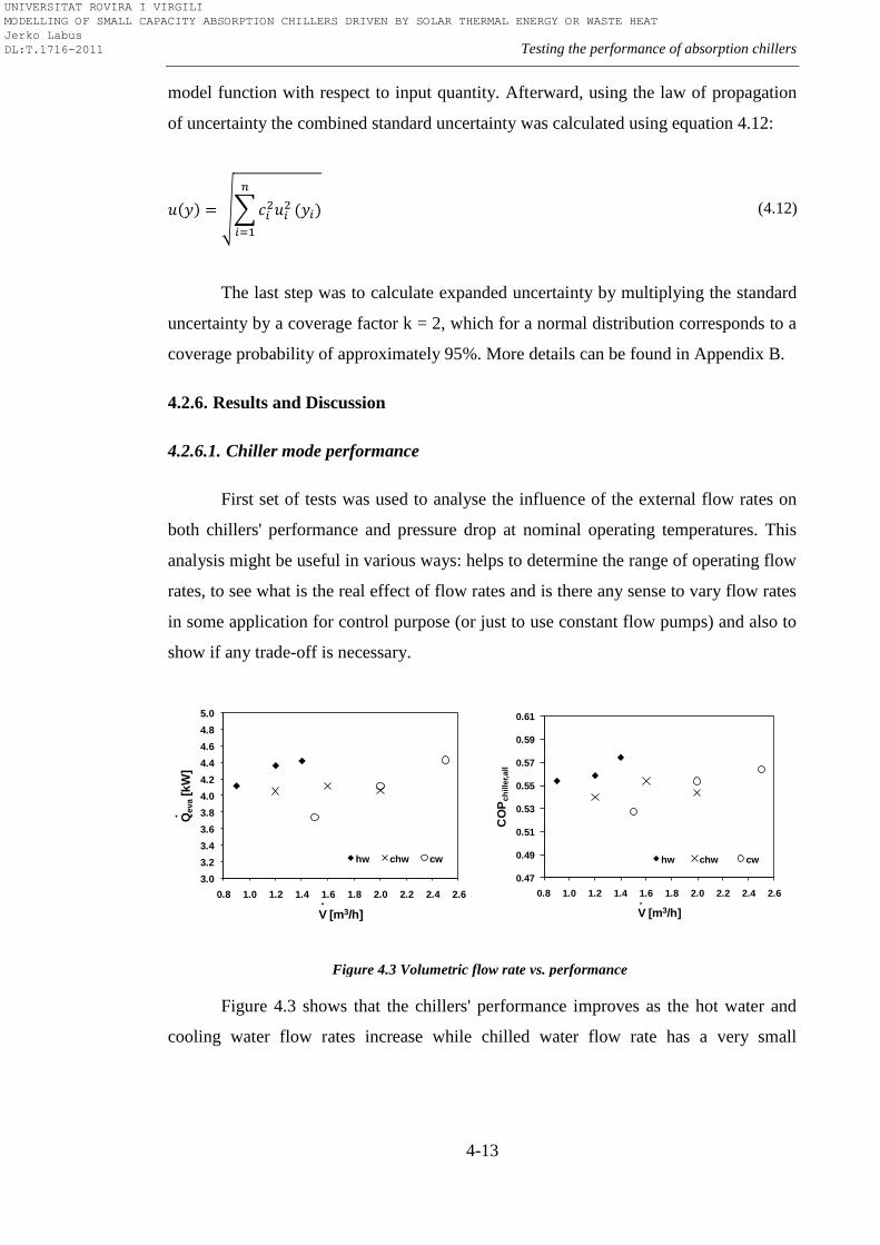
Testing the performance of absorption chillers
4-13
model function with respect to input quantity. Afterward, using the law of propagation
of uncertainty the combined standard uncertainty was calculated using equation 4.12:
(4.12)
The last step was to calculate expanded uncertainty by multiplying the standard
uncertainty by a coverage factor k = 2, which for a normal distribution corresponds to a
coverage probability of approximately 95%. More details can be found in Appendix B.
4.2.6. Results and Discussion
4.2.6.1. Chiller mode performance
First set of tests was used to analyse the influence of the external flow rates on
both chillers' performance and pressure drop at nominal operating temperatures. This
analysis might be useful in various ways: helps to determine the range of operating flow
rates, to see what is the real effect of flow rates and is there any sense to vary flow rates
in some application for control purpose (or just to use constant flow pumps) and also to
show if any trade-off is necessary.
Figure 4.3 Volumetric flow rate vs. performance
Figure 4.3 shows that the chillers' performance improves as the hot water and
cooling water flow rates increase while chilled water flow rate has a very small
3.0
3.2
3.4
3.6
3.8
4.0
4.2
4.4
4.6
4.8
5.0
0.8 1.0 1.2 1.4 1.6 1.8 2.0 2.2 2.4 2.6
Qeva
[kW
]
V [m3/h]
hw chw cw
.
.
0.47
0.49
0.51
0.53
0.55
0.57
0.59
0.61
0.8 1.0 1.2 1.4 1.6 1.8 2.0 2.2 2.4 2.6
CO
Pch
ille
r,all
V [m3/h]
hw chw cw
.
UNIVERSITAT ROVIRA I VIRGILI MODELLING OF SMALL CAPACITY ABSORPTION CHILLERS DRIVEN BY SOLAR THERMAL ENERGY OR WASTE HEAT Jerko Labus DL:T.1716-2011
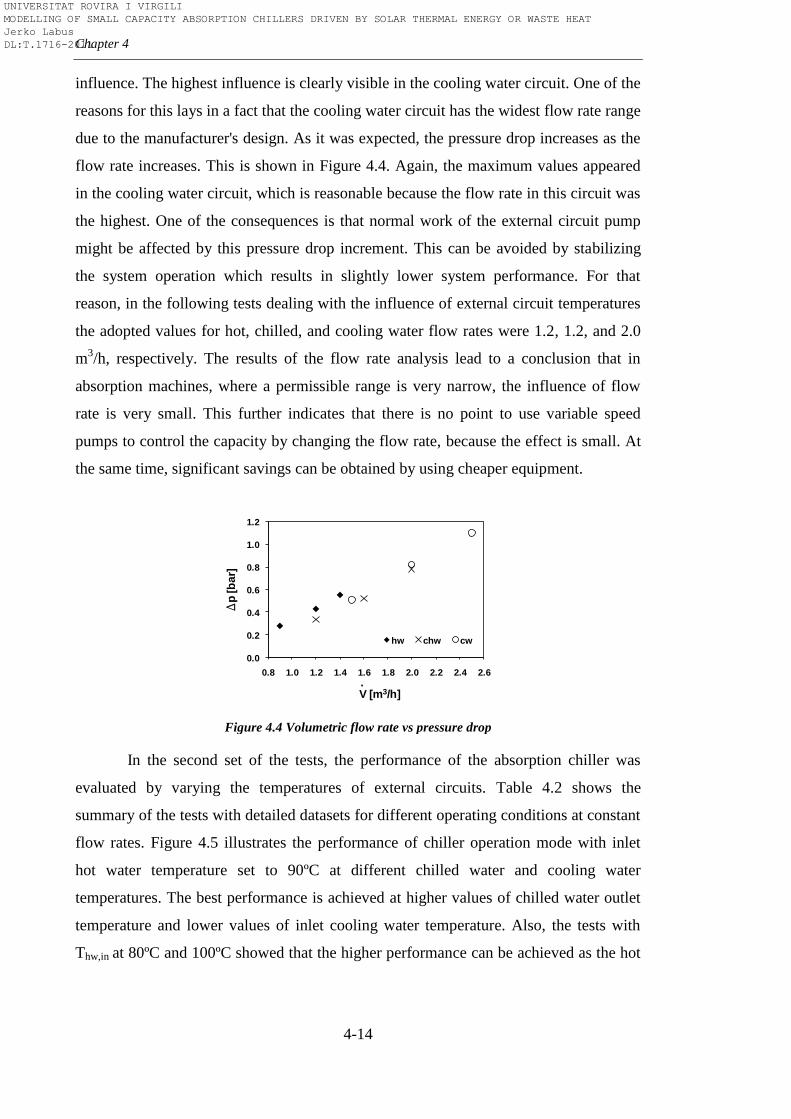
Chapter 4
4-14
influence. The highest influence is clearly visible in the cooling water circuit. One of the
reasons for this lays in a fact that the cooling water circuit has the widest flow rate range
due to the manufacturer's design. As it was expected, the pressure drop increases as the
flow rate increases. This is shown in Figure 4.4. Again, the maximum values appeared
in the cooling water circuit, which is reasonable because the flow rate in this circuit was
the highest. One of the consequences is that normal work of the external circuit pump
might be affected by this pressure drop increment. This can be avoided by stabilizing
the system operation which results in slightly lower system performance. For that
reason, in the following tests dealing with the influence of external circuit temperatures
the adopted values for hot, chilled, and cooling water flow rates were 1.2, 1.2, and 2.0
m3/h, respectively. The results of the flow rate analysis lead to a conclusion that in
absorption machines, where a permissible range is very narrow, the influence of flow
rate is very small. This further indicates that there is no point to use variable speed
pumps to control the capacity by changing the flow rate, because the effect is small. At
the same time, significant savings can be obtained by using cheaper equipment.
Figure 4.4 Volumetric flow rate vs pressure drop
In the second set of the tests, the performance of the absorption chiller was
evaluated by varying the temperatures of external circuits. Table 4.2 shows the
summary of the tests with detailed datasets for different operating conditions at constant
flow rates. Figure 4.5 illustrates the performance of chiller operation mode with inlet
hot water temperature set to 90ºC at different chilled water and cooling water
temperatures. The best performance is achieved at higher values of chilled water outlet
temperature and lower values of inlet cooling water temperature. Also, the tests with
Thw,in at 80ºC and 100ºC showed that the higher performance can be achieved as the hot
0.0
0.2
0.4
0.6
0.8
1.0
1.2
0.8 1.0 1.2 1.4 1.6 1.8 2.0 2.2 2.4 2.6
Dp
[b
ar]
V [m3/h]
hw chw cw
.
UNIVERSITAT ROVIRA I VIRGILI MODELLING OF SMALL CAPACITY ABSORPTION CHILLERS DRIVEN BY SOLAR THERMAL ENERGY OR WASTE HEAT Jerko Labus DL:T.1716-2011
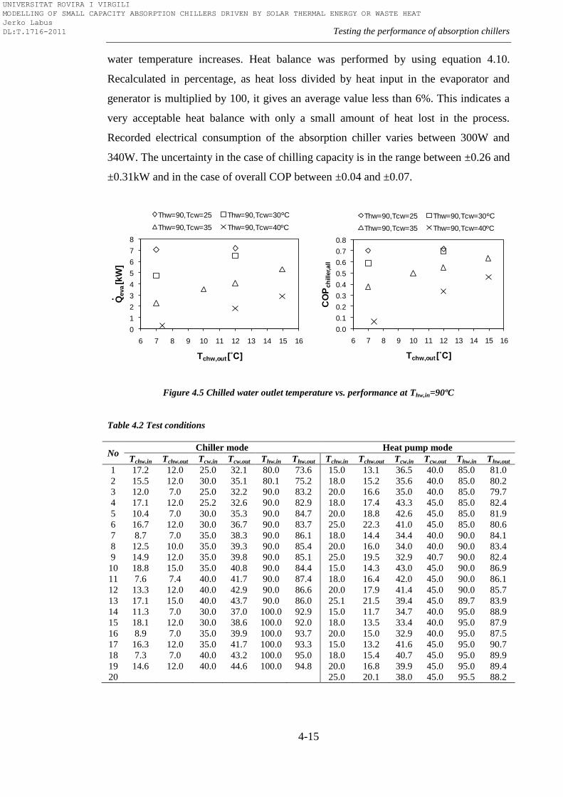
Testing the performance of absorption chillers
4-15
water temperature increases. Heat balance was performed by using equation 4.10.
Recalculated in percentage, as heat loss divided by heat input in the evaporator and
generator is multiplied by 100, it gives an average value less than 6%. This indicates a
very acceptable heat balance with only a small amount of heat lost in the process.
Recorded electrical consumption of the absorption chiller varies between 300W and
340W. The uncertainty in the case of chilling capacity is in the range between ±0.26 and
±0.31kW and in the case of overall COP between ±0.04 and ±0.07.
Figure 4.5 Chilled water outlet temperature vs. performance at Thw,in=90ºC
Table 4.2 Test conditions
No Chiller mode Heat pump mode
Tchw,in Tchw,out Tcw,in Tcw,out Thw,in Thw,out Tchw,in Tchw,out Tcw,in Tcw,out Thw,in Thw,out
1 17.2 12.0 25.0 32.1 80.0 73.6 15.0 13.1 36.5 40.0 85.0 81.0
2 15.5 12.0 30.0 35.1 80.1 75.2 18.0 15.2 35.6 40.0 85.0 80.2
3 12.0 7.0 25.0 32.2 90.0 83.2 20.0 16.6 35.0 40.0 85.0 79.7
4 17.1 12.0 25.2 32.6 90.0 82.9 18.0 17.4 43.3 45.0 85.0 82.4
5 10.4 7.0 30.0 35.3 90.0 84.7 20.0 18.8 42.6 45.0 85.0 81.9
6 16.7 12.0 30.0 36.7 90.0 83.7 25.0 22.3 41.0 45.0 85.0 80.6
7 8.7 7.0 35.0 38.3 90.0 86.1 18.0 14.4 34.4 40.0 90.0 84.1
8 12.5 10.0 35.0 39.3 90.0 85.4 20.0 16.0 34.0 40.0 90.0 83.4
9 14.9 12.0 35.0 39.8 90.0 85.1 25.0 19.5 32.9 40.7 90.0 82.4
10 18.8 15.0 35.0 40.8 90.0 84.4 15.0 14.3 43.0 45.0 90.0 86.9
11 7.6 7.4 40.0 41.7 90.0 87.4 18.0 16.4 42.0 45.0 90.0 86.1
12 13.3 12.0 40.0 42.9 90.0 86.6 20.0 17.9 41.4 45.0 90.0 85.7
13 17.1 15.0 40.0 43.7 90.0 86.0 25.1 21.5 39.4 45.0 89.7 83.9
14 11.3 7.0 30.0 37.0 100.0 92.9 15.0 11.7 34.7 40.0 95.0 88.9
15 18.1 12.0 30.0 38.6 100.0 92.0 18.0 13.5 33.4 40.0 95.0 87.9
16 8.9 7.0 35.0 39.9 100.0 93.7 20.0 15.0 32.9 40.0 95.0 87.5
17 16.3 12.0 35.0 41.7 100.0 93.3 15.0 13.2 41.6 45.0 95.0 90.7
18 7.3 7.0 40.0 43.2 100.0 95.0 18.0 15.4 40.7 45.0 95.0 89.9
19 14.6 12.0 40.0 44.6 100.0 94.8 20.0 16.8 39.9 45.0 95.0 89.4
20 25.0 20.1 38.0 45.0 95.5 88.2
0
1
2
3
4
5
6
7
8
6 7 8 9 10 11 12 13 14 15 16
Qeva [k
W]
Tchw,out [˚C]
Thw=90,Tcw=25 Thw=90,Tcw=30
Thw=90,Tcw=35 Thw=90,Tcw=40
.
ºC
ºC
0.0
0.1
0.2
0.3
0.4
0.5
0.6
0.7
0.8
6 7 8 9 10 11 12 13 14 15 16
CO
Pch
ille
r,all
Tchw,out [˚C]
Thw=90,Tcw=25 Thw=90,Tcw=30
Thw=90,Tcw=35 Thw=90,Tcw=40
ºC
ºC
UNIVERSITAT ROVIRA I VIRGILI MODELLING OF SMALL CAPACITY ABSORPTION CHILLERS DRIVEN BY SOLAR THERMAL ENERGY OR WASTE HEAT Jerko Labus DL:T.1716-2011
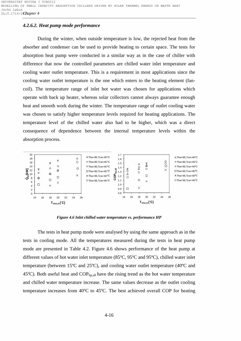
Chapter 4
4-16
4.2.6.2. Heat pump mode performance
During the winter, when outside temperature is low, the rejected heat from the
absorber and condenser can be used to provide heating to certain space. The tests for
absorption heat pump were conducted in a similar way as in the case of chiller with
difference that now the controlled parameters are chilled water inlet temperature and
cooling water outlet temperature. This is a requirement in most applications since the
cooling water outlet temperature is the one which enters to the heating element (fan-
coil). The temperature range of inlet hot water was chosen for applications which
operate with back up heater, whereas solar collectors cannot always guarantee enough
heat and smooth work during the winter. The temperature range of outlet cooling water
was chosen to satisfy higher temperature levels required for heating applications. The
temperature level of the chilled water also had to be higher, which was a direct
consequence of dependence between the internal temperature levels within the
absorption process.
Figure 4.6 Inlet chilled water temperature vs. performance HP
The tests in heat pump mode were analysed by using the same approach as in the
tests in cooling mode. All the temperatures measured during the tests in heat pump
mode are presented in Table 4.2. Figure 4.6 shows performance of the heat pump at
different values of hot water inlet temperature (85ºC, 95ºC and 95ºC), chilled water inlet
temperature (between 15ºC and 25ºC), and cooling water outlet temperature (40ºC and
45ºC). Both useful heat and COPhp,all have the rising trend as the hot water temperature
and chilled water temperature increase. The same values decrease as the outlet cooling
temperature increases from 40ºC to 45ºC. The best achieved overall COP for heating
0
2
4
6
8
10
12
14
16
18
20
14 16 18 20 22 24 26
Qac[k
W]
Tchw,in [˚C]
Thw=85,Tcw=40
Thw=85,Tcw=45
Thw=90,Tcw=40
Thw=90,Tcw=45
Thw=95,Tcw=40
Thw=95,Tcw=45
ºC
ºC
ºC
ºC
ºC
ºC.
0.8
0.9
1.0
1.1
1.2
1.3
1.4
1.5
1.6
1.7
14 16 18 20 22 24 26
CO
Ph
p,a
ll
Tchw,in [˚C]
Thw=85,Tcw=40
Thw=85,Tcw=45
Thw=90,Tcw=40
Thw=90,Tcw=45
Thw=95,Tcw=40
Thw=95,Tcw=45
ºC
ºC
ºC
ºC
ºC
ºC
UNIVERSITAT ROVIRA I VIRGILI MODELLING OF SMALL CAPACITY ABSORPTION CHILLERS DRIVEN BY SOLAR THERMAL ENERGY OR WASTE HEAT Jerko Labus DL:T.1716-2011
Testing the performance of absorption chillers
4-17
has value close to 1.6 (Figure 4.6). The value of thermal COP is slightly higher, around
1.7. Some additional tests were conducted in order to explore the limits of the outlet
cooling water temperature. In the test when Thw=90ºC, Tcw=48ºC and Tchw=20ºC the
recorded useful heat was 4.39kW and corresponding COPhp,all equal to 0.87. The poor
performance as well as the difficulty to maintain steady-state conditions indicates that
around 48ºC would be limiting temperature for heating applications. Analysis based on
pressure drop confirmed that change of temperatures in external circuits has negligible
influence on pressure drop. Recorded electrical consumption of the absorption heat
pump varies between 300 and 340 W, same as in the case of chiller. Heat balance gives
averaged value for heat loss of around 0.5kW or less than 7%. Again, error analysis
confirmed that all the calculated quantities are in the range of estimated uncertainties.
4.3. Stage two
A procedure which contains all the necessary elements to describe the
absorption machine behaviour in steady-state conditions with sufficient accuracy was
established in the Stage one. The procedure, based only on external manipulable
parameters, provides sufficient information to understand behaviour of the absorption
machine in different operating modes which can be useful in various applications of
interest. The previous experience and knowledge generated in the field of experimental
research were used for its establishment. At the same time, the tests performed in the
Stage one served to validate two operating modes of the multifunctional test bench:
chiller and heat pump modes.
However, the wish was to improve the test procedure, making it the more robust,
especially in the field of steady-state identification. Therefore, extensive literature
review has been carried out on methods of steady-state identification, in order to
develop a steady-state detector which will help in creation of high quality database.
Another question appeared with regard to our objective of creating database(s) which
will be used for the modelling of absorption machines: which is the number of samples
(number of different steady-state conditions) required to obtain precise estimate of the
absorption machine empirical model developed on experimental data? According to
[135], ―if the relationship between the input and output parameters of the model is not
UNIVERSITAT ROVIRA I VIRGILI MODELLING OF SMALL CAPACITY ABSORPTION CHILLERS DRIVEN BY SOLAR THERMAL ENERGY OR WASTE HEAT Jerko Labus DL:T.1716-2011
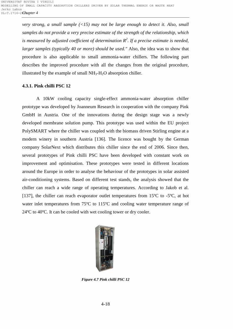
Chapter 4
4-18
very strong, a small sample (<15) may not be large enough to detect it. Also, small
samples do not provide a very precise estimate of the strength of the relationship, which
is measured by adjusted coefficient of determination R2. If a precise estimate is needed,
larger samples (typically 40 or more) should be used." Also, the idea was to show that
procedure is also applicable to small ammonia-water chillers. The following part
describes the improved procedure with all the changes from the original procedure,
illustrated by the example of small NH3-H2O absorption chiller.
4.3.1. Pink chilli PSC 12
A 10kW cooling capacity single-effect ammonia-water absorption chiller
prototype was developed by Joanneum Research in cooperation with the company Pink
GmbH in Austria. One of the innovations during the design stage was a newly
developed membrane solution pump. This prototype was used within the EU project
PolySMART where the chiller was coupled with the biomass driven Stirling engine at a
modern winery in southern Austria [136]. The licence was bought by the German
company SolarNext which distributes this chiller since the end of 2006. Since then,
several prototypes of Pink chilli PSC have been developed with constant work on
improvement and optimisation. These prototypes were tested in different locations
around the Europe in order to analyse the behaviour of the prototypes in solar assisted
air-conditioning systems. Based on different test stands, the analysis showed that the
chiller can reach a wide range of operating temperatures. According to Jakob et al.
[137], the chiller can reach evaporator outlet temperatures from 15ºC to -5ºC, at hot
water inlet temperatures from 75ºC to 115ºC and cooling water temperature range of
24ºC to 40ºC. It can be cooled with wet cooling tower or dry cooler.
Figure 4.7 Pink chilli PSC 12
UNIVERSITAT ROVIRA I VIRGILI MODELLING OF SMALL CAPACITY ABSORPTION CHILLERS DRIVEN BY SOLAR THERMAL ENERGY OR WASTE HEAT Jerko Labus DL:T.1716-2011
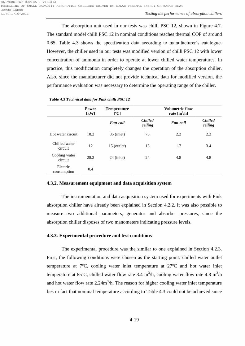
Testing the performance of absorption chillers
4-19
The absorption unit used in our tests was chilli PSC 12, shown in Figure 4.7.
The standard model chilli PSC 12 in nominal conditions reaches thermal COP of around
0.65. Table 4.3 shows the specification data according to manufacturer’s catalogue.
However, the chiller used in our tests was modified version of chilli PSC 12 with lower
concentration of ammonia in order to operate at lower chilled water temperatures. In
practice, this modification completely changes the operation of the absorption chiller.
Also, since the manufacturer did not provide technical data for modified version, the
performance evaluation was necessary to determine the operating range of the chiller.
Table 4.3 Technical data for Pink chilli PSC 12
Power
[kW]
Temperature
[ºC]
Volumetric flow
rate [m3/h]
Fan-coil Chilled
ceiling Fan-coil
Chilled
ceiling
Hot water circuit 18.2 85 (inlet) 75 2.2 2.2
Chilled water
circuit 12 15 (outlet) 15 1.7 3.4
Cooling water
circuit 28.2 24 (inlet) 24 4.8 4.8
Electric
consumption 0.4
4.3.2. Measurement equipment and data acquisition system
The instrumentation and data acquisition system used for experiments with Pink
absorption chiller have already been explained in Section 4.2.2. It was also possible to
measure two additional parameters, generator and absorber pressures, since the
absorption chiller disposes of two manometers indicating pressure levels.
4.3.3. Experimental procedure and test conditions
The experimental procedure was the similar to one explained in Section 4.2.3.
First, the following conditions were chosen as the starting point: chilled water outlet
temperature at 7ºC, cooling water inlet temperature at 27ºC and hot water inlet
temperature at 85ºC, chilled water flow rate 3.4 m3/h, cooling water flow rate 4.8 m
3/h
and hot water flow rate 2.24m3/h. The reason for higher cooling water inlet temperature
lies in fact that nominal temperature according to Table 4.3 could not be achieved since
UNIVERSITAT ROVIRA I VIRGILI MODELLING OF SMALL CAPACITY ABSORPTION CHILLERS DRIVEN BY SOLAR THERMAL ENERGY OR WASTE HEAT Jerko Labus DL:T.1716-2011
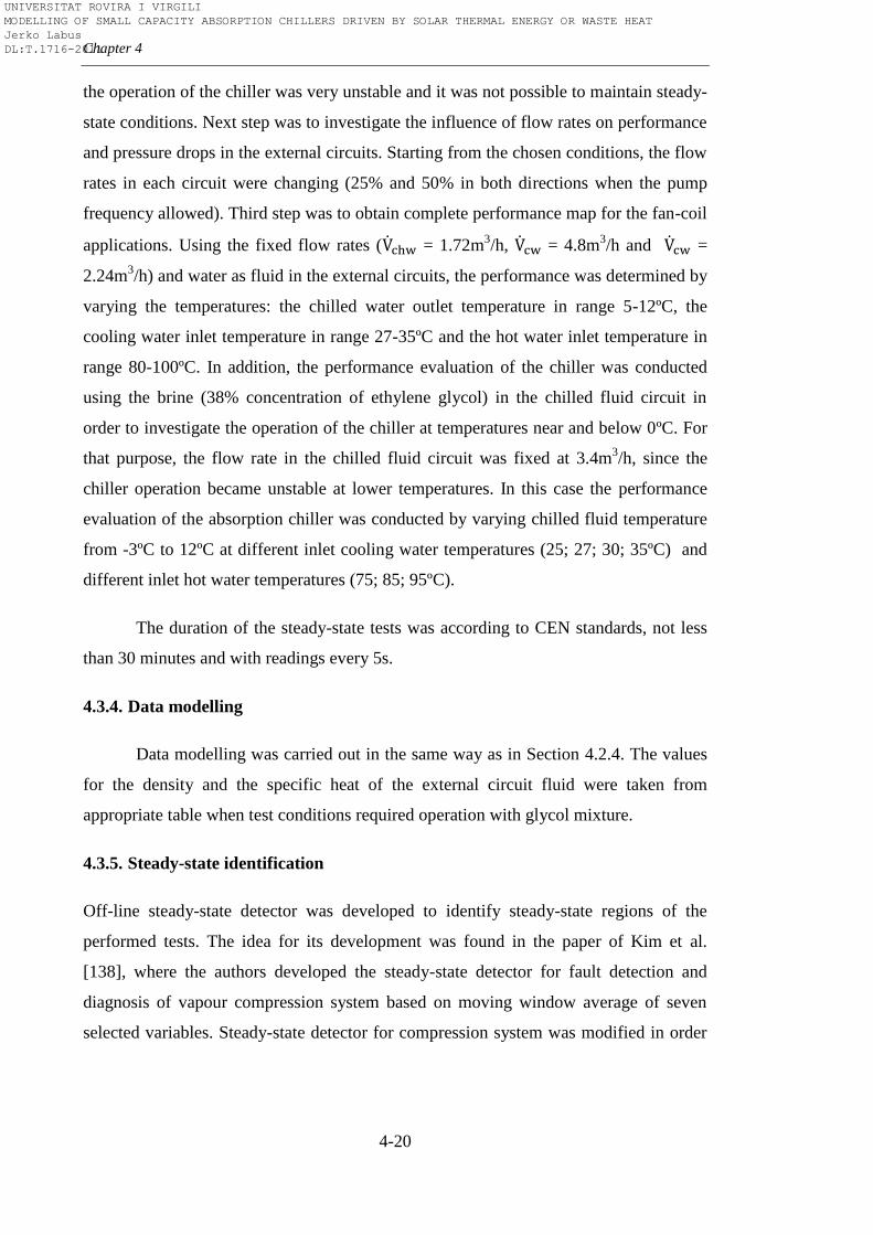
Chapter 4
4-20
the operation of the chiller was very unstable and it was not possible to maintain steady-
state conditions. Next step was to investigate the influence of flow rates on performance
and pressure drops in the external circuits. Starting from the chosen conditions, the flow
rates in each circuit were changing (25% and 50% in both directions when the pump
frequency allowed). Third step was to obtain complete performance map for the fan-coil
applications. Using the fixed flow rates ( = 1.72m3/h, = 4.8m
3/h and =
2.24m3/h) and water as fluid in the external circuits, the performance was determined by
varying the temperatures: the chilled water outlet temperature in range 5-12ºC, the
cooling water inlet temperature in range 27-35ºC and the hot water inlet temperature in
range 80-100ºC. In addition, the performance evaluation of the chiller was conducted
using the brine (38% concentration of ethylene glycol) in the chilled fluid circuit in
order to investigate the operation of the chiller at temperatures near and below 0ºC. For
that purpose, the flow rate in the chilled fluid circuit was fixed at 3.4m3/h, since the
chiller operation became unstable at lower temperatures. In this case the performance
evaluation of the absorption chiller was conducted by varying chilled fluid temperature
from -3ºC to 12ºC at different inlet cooling water temperatures (25; 27; 30; 35ºC) and
different inlet hot water temperatures (75; 85; 95ºC).
The duration of the steady-state tests was according to CEN standards, not less
than 30 minutes and with readings every 5s.
4.3.4. Data modelling
Data modelling was carried out in the same way as in Section 4.2.4. The values
for the density and the specific heat of the external circuit fluid were taken from
appropriate table when test conditions required operation with glycol mixture.
4.3.5. Steady-state identification
Off-line steady-state detector was developed to identify steady-state regions of the
performed tests. The idea for its development was found in the paper of Kim et al.
[138], where the authors developed the steady-state detector for fault detection and
diagnosis of vapour compression system based on moving window average of seven
selected variables. Steady-state detector for compression system was modified in order
UNIVERSITAT ROVIRA I VIRGILI MODELLING OF SMALL CAPACITY ABSORPTION CHILLERS DRIVEN BY SOLAR THERMAL ENERGY OR WASTE HEAT Jerko Labus DL:T.1716-2011
Testing the performance of absorption chillers
4-21
to correspond to absorption systems. Several improvements were added to new steady-
state detector. These improvements refer to the additional data filter which eliminates
remaining transient periods caused by time delays when changing from one steady-state
to another and two additional checks to confirm steady-state conditions. In detail
procedure for development of absorption system steady-state detector as well as
comprehensive literature review are provided in Appendix C.
4.3.6. Uncertainty estimation
The estimation of uncertainties was realized in the same manner already
explained in Section 4.2.5. In addition, the uncertainty estimation can serve as
additional check for our steady-state detection process. After calculation of uncertainty
for the derived variables (loads, COPs), the minimum and the maximum values of the
readings (of the derived variable) within the observed steady-state interval should be
within the calculated uncertainty bounds from the average value.
4.3.7. Automation of the procedure
The entire procedure described above can be (semi)automated in a way
illustrated in Figure 4.8.
Figure 4.8 Test procedure flowchart
Raw data
Steady state detector
(moving window)
Data modelling
Uncertainty estimation
Steady state
database
Check I
Additional steady
state filter
Check II
UNIVERSITAT ROVIRA I VIRGILI MODELLING OF SMALL CAPACITY ABSORPTION CHILLERS DRIVEN BY SOLAR THERMAL ENERGY OR WASTE HEAT Jerko Labus DL:T.1716-2011
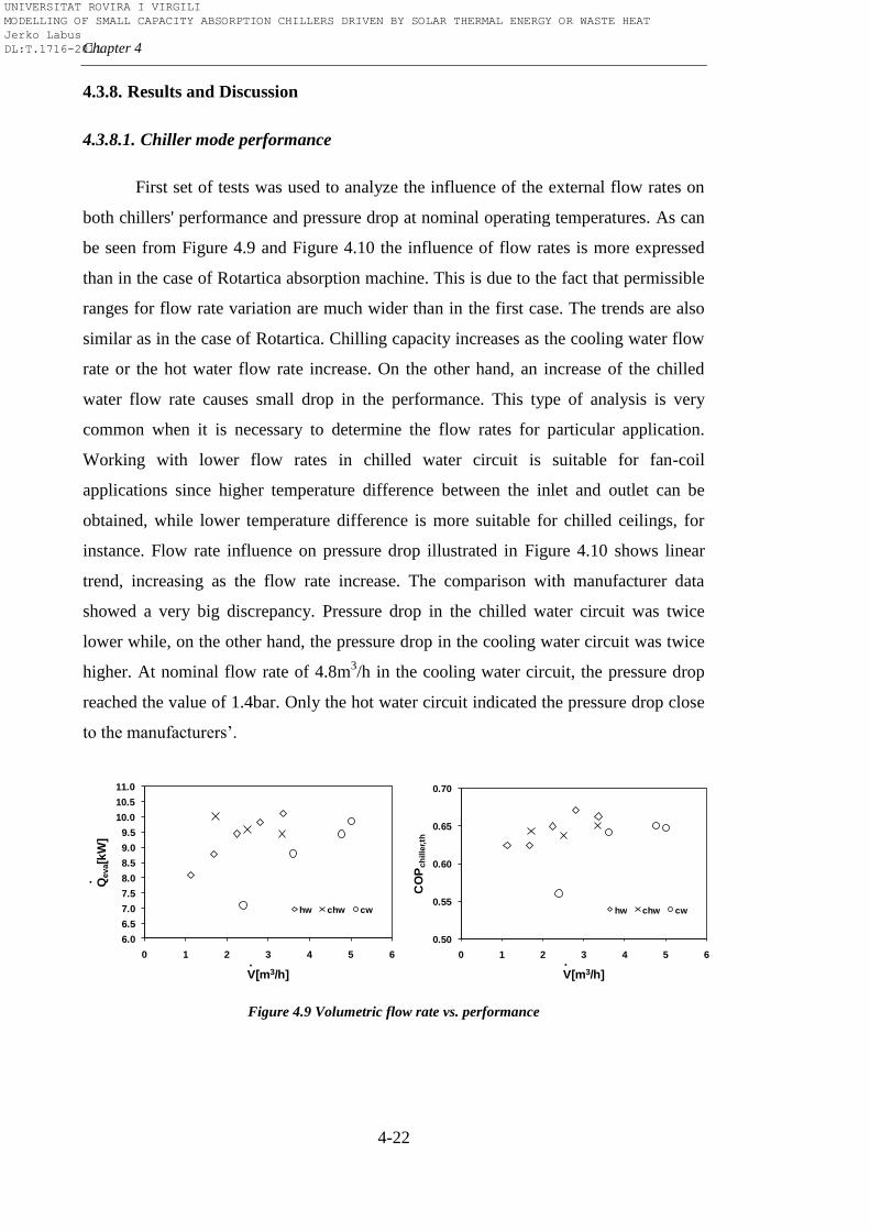
Chapter 4
4-22
4.3.8. Results and Discussion
4.3.8.1. Chiller mode performance
First set of tests was used to analyze the influence of the external flow rates on
both chillers' performance and pressure drop at nominal operating temperatures. As can
be seen from Figure 4.9 and Figure 4.10 the influence of flow rates is more expressed
than in the case of Rotartica absorption machine. This is due to the fact that permissible
ranges for flow rate variation are much wider than in the first case. The trends are also
similar as in the case of Rotartica. Chilling capacity increases as the cooling water flow
rate or the hot water flow rate increase. On the other hand, an increase of the chilled
water flow rate causes small drop in the performance. This type of analysis is very
common when it is necessary to determine the flow rates for particular application.
Working with lower flow rates in chilled water circuit is suitable for fan-coil
applications since higher temperature difference between the inlet and outlet can be
obtained, while lower temperature difference is more suitable for chilled ceilings, for
instance. Flow rate influence on pressure drop illustrated in Figure 4.10 shows linear
trend, increasing as the flow rate increase. The comparison with manufacturer data
showed a very big discrepancy. Pressure drop in the chilled water circuit was twice
lower while, on the other hand, the pressure drop in the cooling water circuit was twice
higher. At nominal flow rate of 4.8m3/h in the cooling water circuit, the pressure drop
reached the value of 1.4bar. Only the hot water circuit indicated the pressure drop close
to the manufacturers’.
Figure 4.9 Volumetric flow rate vs. performance
6.0
6.5
7.0
7.5
8.0
8.5
9.0
9.5
10.0
10.5
11.0
0 1 2 3 4 5 6
Qeva[k
W]
V[m3/h]
hw chw cw
.
.
0.50
0.55
0.60
0.65
0.70
0 1 2 3 4 5 6
CO
Pch
ille
r,th
V[m3/h]
hw chw cw
.
UNIVERSITAT ROVIRA I VIRGILI MODELLING OF SMALL CAPACITY ABSORPTION CHILLERS DRIVEN BY SOLAR THERMAL ENERGY OR WASTE HEAT Jerko Labus DL:T.1716-2011
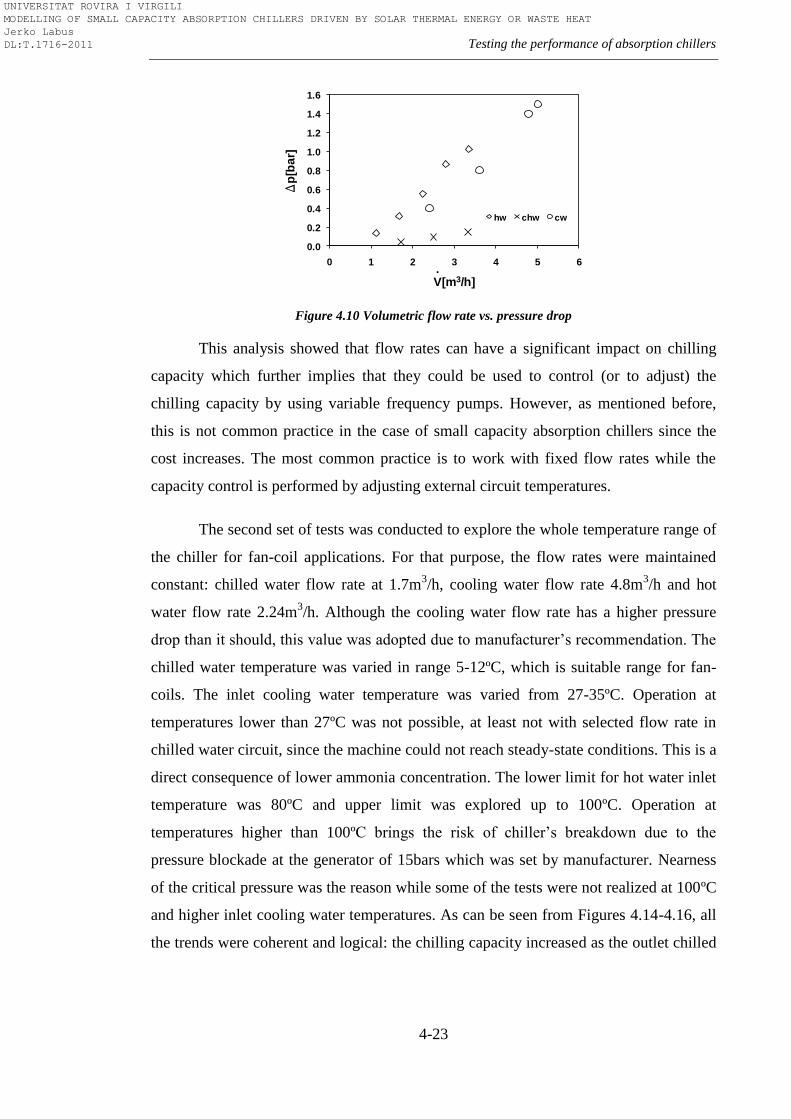
Testing the performance of absorption chillers
4-23
Figure 4.10 Volumetric flow rate vs. pressure drop
This analysis showed that flow rates can have a significant impact on chilling
capacity which further implies that they could be used to control (or to adjust) the
chilling capacity by using variable frequency pumps. However, as mentioned before,
this is not common practice in the case of small capacity absorption chillers since the
cost increases. The most common practice is to work with fixed flow rates while the
capacity control is performed by adjusting external circuit temperatures.
The second set of tests was conducted to explore the whole temperature range of
the chiller for fan-coil applications. For that purpose, the flow rates were maintained
constant: chilled water flow rate at 1.7m3/h, cooling water flow rate 4.8m
3/h and hot
water flow rate 2.24m3/h. Although the cooling water flow rate has a higher pressure
drop than it should, this value was adopted due to manufacturer’s recommendation. The
chilled water temperature was varied in range 5-12ºC, which is suitable range for fan-
coils. The inlet cooling water temperature was varied from 27-35ºC. Operation at
temperatures lower than 27ºC was not possible, at least not with selected flow rate in
chilled water circuit, since the machine could not reach steady-state conditions. This is a
direct consequence of lower ammonia concentration. The lower limit for hot water inlet
temperature was 80ºC and upper limit was explored up to 100ºC. Operation at
temperatures higher than 100ºC brings the risk of chiller’s breakdown due to the
pressure blockade at the generator of 15bars which was set by manufacturer. Nearness
of the critical pressure was the reason while some of the tests were not realized at 100ºC
and higher inlet cooling water temperatures. As can be seen from Figures 4.14-4.16, all
the trends were coherent and logical: the chilling capacity increased as the outlet chilled
0.0
0.2
0.4
0.6
0.8
1.0
1.2
1.4
1.6
0 1 2 3 4 5 6
Dp
[ba
r]V[m3/h]
hw chw cw
.
UNIVERSITAT ROVIRA I VIRGILI MODELLING OF SMALL CAPACITY ABSORPTION CHILLERS DRIVEN BY SOLAR THERMAL ENERGY OR WASTE HEAT Jerko Labus DL:T.1716-2011
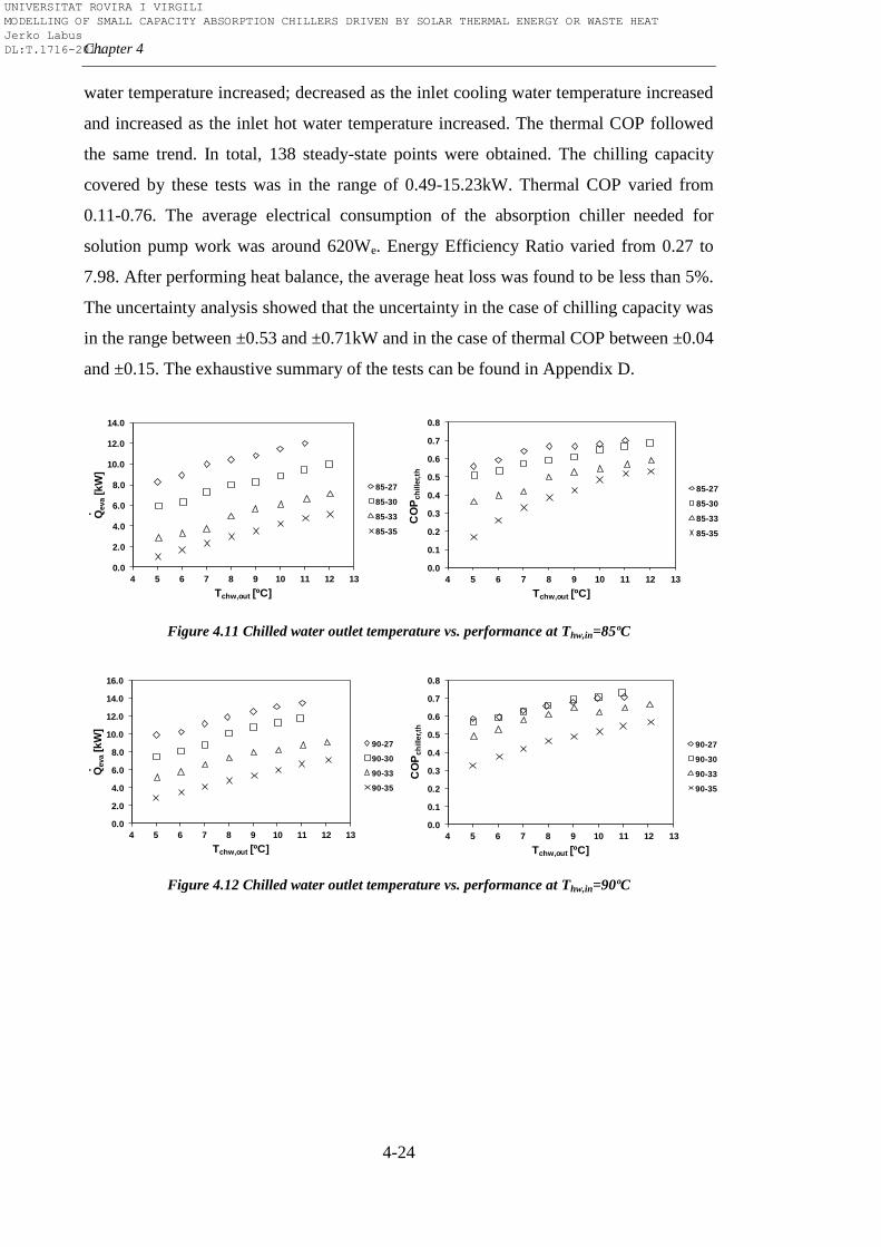
Chapter 4
4-24
water temperature increased; decreased as the inlet cooling water temperature increased
and increased as the inlet hot water temperature increased. The thermal COP followed
the same trend. In total, 138 steady-state points were obtained. The chilling capacity
covered by these tests was in the range of 0.49-15.23kW. Thermal COP varied from
0.11-0.76. The average electrical consumption of the absorption chiller needed for
solution pump work was around 620We. Energy Efficiency Ratio varied from 0.27 to
7.98. After performing heat balance, the average heat loss was found to be less than 5%.
The uncertainty analysis showed that the uncertainty in the case of chilling capacity was
in the range between ±0.53 and ±0.71kW and in the case of thermal COP between ±0.04
and ±0.15. The exhaustive summary of the tests can be found in Appendix D.
Figure 4.11 Chilled water outlet temperature vs. performance at Thw,in=85ºC
Figure 4.12 Chilled water outlet temperature vs. performance at Thw,in=90ºC
0.0
2.0
4.0
6.0
8.0
10.0
12.0
14.0
4 5 6 7 8 9 10 11 12 13
Qeva
[kW
]
Tchw,out [ºC]
85-27
85-30
85-33
85-35
.
0.0
0.1
0.2
0.3
0.4
0.5
0.6
0.7
0.8
4 5 6 7 8 9 10 11 12 13
CO
Pch
ille
r,th
Tchw,out [ºC]
85-27
85-30
85-33
85-35
0.0
2.0
4.0
6.0
8.0
10.0
12.0
14.0
16.0
4 5 6 7 8 9 10 11 12 13
Qeva
[kW
]
Tchw,out [ºC]
90-27
90-30
90-33
90-35
.
0.0
0.1
0.2
0.3
0.4
0.5
0.6
0.7
0.8
4 5 6 7 8 9 10 11 12 13
CO
Pch
ille
r,th
Tchw,out [ºC]
90-27
90-30
90-33
90-35
UNIVERSITAT ROVIRA I VIRGILI MODELLING OF SMALL CAPACITY ABSORPTION CHILLERS DRIVEN BY SOLAR THERMAL ENERGY OR WASTE HEAT Jerko Labus DL:T.1716-2011
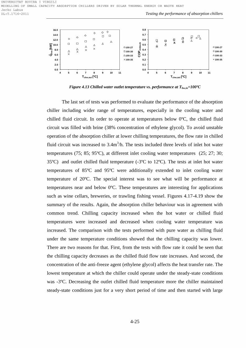
Testing the performance of absorption chillers
4-25
Figure 4.13 Chilled water outlet temperature vs. performance at Thw,in=100ºC
The last set of tests was performed to evaluate the performance of the absorption
chiller including wider range of temperatures, especially in the cooling water and
chilled fluid circuit. In order to operate at temperatures below 0ºC, the chilled fluid
circuit was filled with brine (38% concentration of ethylene glycol). To avoid unstable
operation of the absorption chiller at lower chilling temperatures, the flow rate in chilled
fluid circuit was increased to 3.4m3/h. The tests included three levels of inlet hot water
temperatures (75; 85; 95ºC), at different inlet cooling water temperatures (25; 27; 30;
35ºC) and outlet chilled fluid temperature (-3ºC to 12ºC). The tests at inlet hot water
temperatures of 85ºC and 95ºC were additionally extended to inlet cooling water
temperature of 20ºC. The special interest was to see what will be performance at
temperatures near and below 0ºC. These temperatures are interesting for applications
such as wine cellars, breweries, or trawling fishing vessel. Figures 4.17-4.19 show the
summary of the results. Again, the absorption chiller behaviour was in agreement with
common trend. Chilling capacity increased when the hot water or chilled fluid
temperatures were increased and decreased when cooling water temperature was
increased. The comparison with the tests performed with pure water as chilling fluid
under the same temperature conditions showed that the chilling capacity was lower.
There are two reasons for that. First, from the tests with flow rate it could be seen that
the chilling capacity decreases as the chilled fluid flow rate increases. And second, the
concentration of the anti-freeze agent (ethylene glycol) affects the heat transfer rate. The
lowest temperature at which the chiller could operate under the steady-state conditions
was -3ºC. Decreasing the outlet chilled fluid temperature more the chiller maintained
steady-state conditions just for a very short period of time and then started with large
0.0
2.0
4.0
6.0
8.0
10.0
12.0
14.0
16.0
4 5 6 7 8 9 10 11
Qeva
[kW
]
Tchw,out [ºC]
100-27
100-30
100-33
100-35
.
0.0
0.1
0.2
0.3
0.4
0.5
0.6
0.7
0.8
4 5 6 7 8 9 10 11
CO
Pch
ille
r,th
Tchw,out [ºC]
100-27
100-30
100-33
100-35
UNIVERSITAT ROVIRA I VIRGILI MODELLING OF SMALL CAPACITY ABSORPTION CHILLERS DRIVEN BY SOLAR THERMAL ENERGY OR WASTE HEAT Jerko Labus DL:T.1716-2011
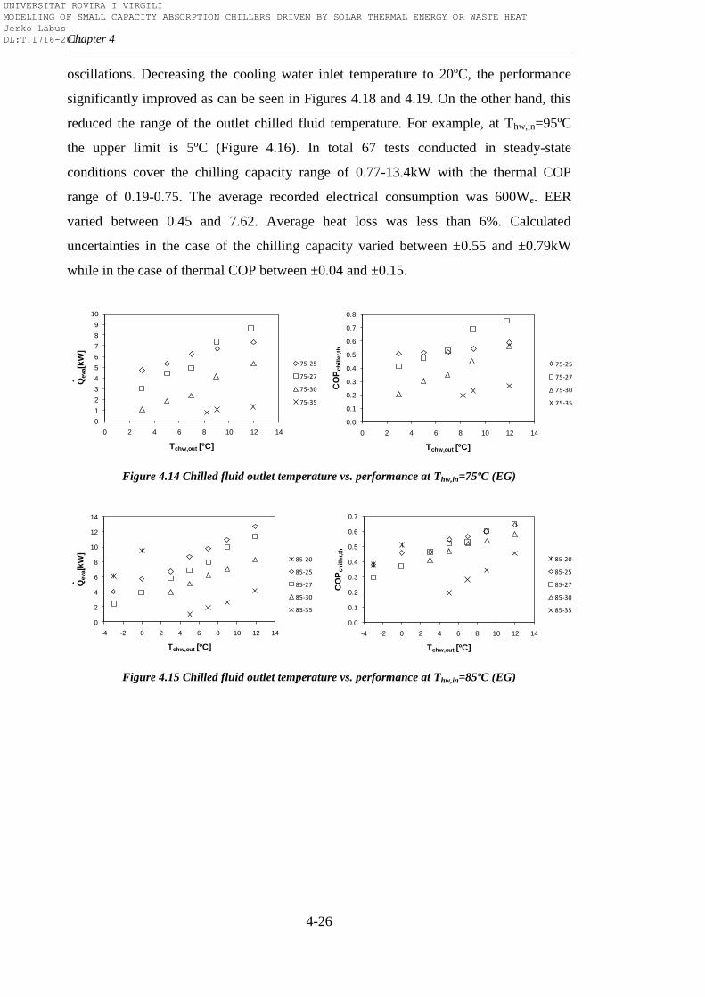
Chapter 4
4-26
oscillations. Decreasing the cooling water inlet temperature to 20ºC, the performance
significantly improved as can be seen in Figures 4.18 and 4.19. On the other hand, this
reduced the range of the outlet chilled fluid temperature. For example, at Thw,in=95ºC
the upper limit is 5ºC (Figure 4.16). In total 67 tests conducted in steady-state
conditions cover the chilling capacity range of 0.77-13.4kW with the thermal COP
range of 0.19-0.75. The average recorded electrical consumption was 600We. EER
varied between 0.45 and 7.62. Average heat loss was less than 6%. Calculated
uncertainties in the case of the chilling capacity varied between ±0.55 and ±0.79kW
while in the case of thermal COP between ±0.04 and ±0.15.
Figure 4.14 Chilled fluid outlet temperature vs. performance at Thw,in=75ºC (EG)
Figure 4.15 Chilled fluid outlet temperature vs. performance at Thw,in=85ºC (EG)
0
1
2
3
4
5
6
7
8
9
10
0 2 4 6 8 10 12 14
Qeva[k
W]
Tchw,out [ºC]
75-25
75-27
75-30
75-35
.
0.0
0.1
0.2
0.3
0.4
0.5
0.6
0.7
0.8
0 2 4 6 8 10 12 14
CO
Pch
ille
r,th
Tchw,out [ºC]
75-25
75-27
75-30
75-35
0
2
4
6
8
10
12
14
-4 -2 0 2 4 6 8 10 12 14
Qeva[k
W]
Tchw,out [ºC]
85-20
85-25
85-27
85-30
85-35
.
0.0
0.1
0.2
0.3
0.4
0.5
0.6
0.7
-4 -2 0 2 4 6 8 10 12 14
CO
Pch
ille
r,th
Tchw,out [ºC]
85-20
85-25
85-27
85-30
85-35
UNIVERSITAT ROVIRA I VIRGILI MODELLING OF SMALL CAPACITY ABSORPTION CHILLERS DRIVEN BY SOLAR THERMAL ENERGY OR WASTE HEAT Jerko Labus DL:T.1716-2011
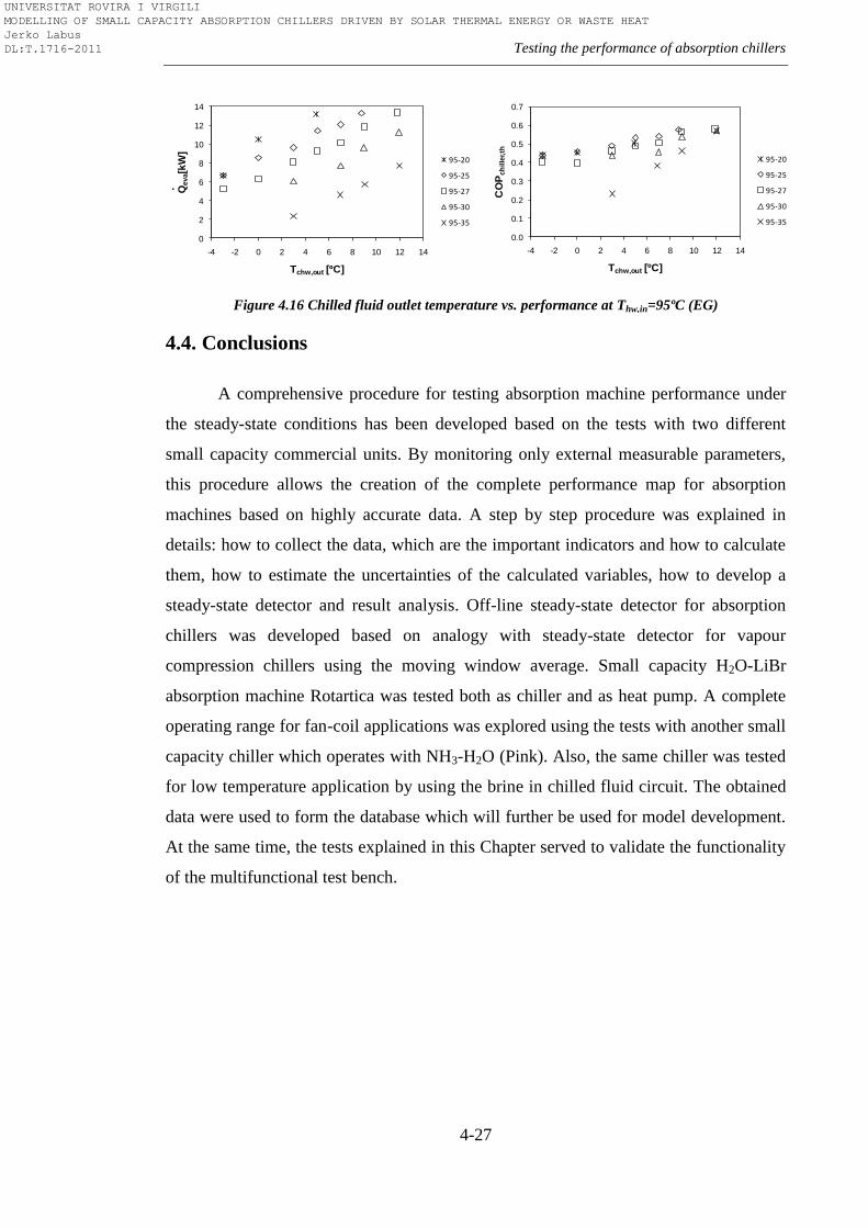
Testing the performance of absorption chillers
4-27
Figure 4.16 Chilled fluid outlet temperature vs. performance at Thw,in=95ºC (EG)
4.4. Conclusions
A comprehensive procedure for testing absorption machine performance under
the steady-state conditions has been developed based on the tests with two different
small capacity commercial units. By monitoring only external measurable parameters,
this procedure allows the creation of the complete performance map for absorption
machines based on highly accurate data. A step by step procedure was explained in
details: how to collect the data, which are the important indicators and how to calculate
them, how to estimate the uncertainties of the calculated variables, how to develop a
steady-state detector and result analysis. Off-line steady-state detector for absorption
chillers was developed based on analogy with steady-state detector for vapour
compression chillers using the moving window average. Small capacity H2O-LiBr
absorption machine Rotartica was tested both as chiller and as heat pump. A complete
operating range for fan-coil applications was explored using the tests with another small
capacity chiller which operates with NH3-H2O (Pink). Also, the same chiller was tested
for low temperature application by using the brine in chilled fluid circuit. The obtained
data were used to form the database which will further be used for model development.
At the same time, the tests explained in this Chapter served to validate the functionality
of the multifunctional test bench.
0
2
4
6
8
10
12
14
-4 -2 0 2 4 6 8 10 12 14
Qeva[k
W]
Tchw,out [ºC]
95-20
95-25
95-27
95-30
95-35
.
0.0
0.1
0.2
0.3
0.4
0.5
0.6
0.7
-4 -2 0 2 4 6 8 10 12 14
CO
Pch
ille
r,th
Tchw,out [ºC]
95-20
95-25
95-27
95-30
95-35
UNIVERSITAT ROVIRA I VIRGILI MODELLING OF SMALL CAPACITY ABSORPTION CHILLERS DRIVEN BY SOLAR THERMAL ENERGY OR WASTE HEAT Jerko Labus DL:T.1716-2011

UNIVERSITAT ROVIRA I VIRGILI MODELLING OF SMALL CAPACITY ABSORPTION CHILLERS DRIVEN BY SOLAR THERMAL ENERGY OR WASTE HEAT Jerko Labus DL:T.1716-2011
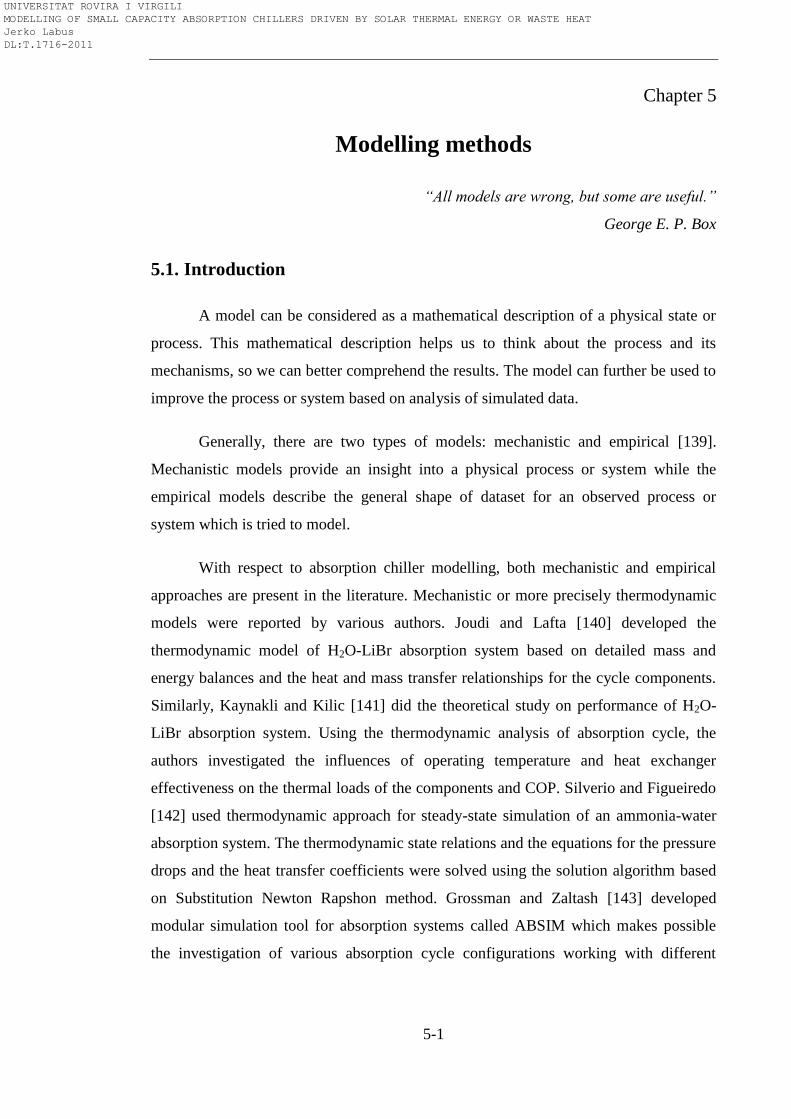
5-1
Chapter 5
Modelling methods
“All models are wrong, but some are useful.”
George E. P. Box
5.1. Introduction
A model can be considered as a mathematical description of a physical state or
process. This mathematical description helps us to think about the process and its
mechanisms, so we can better comprehend the results. The model can further be used to
improve the process or system based on analysis of simulated data.
Generally, there are two types of models: mechanistic and empirical [139].
Mechanistic models provide an insight into a physical process or system while the
empirical models describe the general shape of dataset for an observed process or
system which is tried to model.
With respect to absorption chiller modelling, both mechanistic and empirical
approaches are present in the literature. Mechanistic or more precisely thermodynamic
models were reported by various authors. Joudi and Lafta [140] developed the
thermodynamic model of H2O-LiBr absorption system based on detailed mass and
energy balances and the heat and mass transfer relationships for the cycle components.
Similarly, Kaynakli and Kilic [141] did the theoretical study on performance of H2O-
LiBr absorption system. Using the thermodynamic analysis of absorption cycle, the
authors investigated the influences of operating temperature and heat exchanger
effectiveness on the thermal loads of the components and COP. Silverio and Figueiredo
[142] used thermodynamic approach for steady-state simulation of an ammonia-water
absorption system. The thermodynamic state relations and the equations for the pressure
drops and the heat transfer coefficients were solved using the solution algorithm based
on Substitution Newton Rapshon method. Grossman and Zaltash [143] developed
modular simulation tool for absorption systems called ABSIM which makes possible
the investigation of various absorption cycle configurations working with different
UNIVERSITAT ROVIRA I VIRGILI MODELLING OF SMALL CAPACITY ABSORPTION CHILLERS DRIVEN BY SOLAR THERMAL ENERGY OR WASTE HEAT Jerko Labus DL:T.1716-2011
Chapter 5
5-2
fluids. Based on a user-supplied cycled diagram, working fluid specification and given
operating conditions, ABSIM calculates the internal state points and thermal loads of
the components. This is enabled through the subroutines which contain the governing
equations for each component of the cycle. Garimella et al. [144] used ABSIM to model
and to evaluate the performance of a Generator Absorber heat eXchanger (GAX) heat
pump. However, thermodynamic models are very demanding since they require
comprehensive knowledge of the absorption cycle including all internal state points.
The model needs lots of input parameters such as heat transfer coefficients (U) and heat
transfer areas (A) of heat exchangers, solution flow rate, working fluid properties and
water side flows and temperatures as well as some additional assumptions for
convenience of modelling. In most of the cases, especially with commercial units, the
internal parameters are not available. This is the reason why thermodynamic models are
more adequate during the design stage of absorption equipment [145]. The computation
time in simulation software packages is very long since these models require a lot of
simultaneous iterations. The annual simulations of different systems on hourly time step
basis are more than evident proof for that fact. Thus, there is a need for simple models
which can provide sufficiently good representation of the absorption machine behaviour
based only on available external parameters (experimental measurements or
manufacturer catalogue data). Simple models can easily be incorporated in simulation
programs or used for fault detection and control. Contrary to the mechanistic models,
the empirical and semi-empirical models require less time and effort to develop and
computation time is much shorter when they are built-in simulation programs. The
parameters and fitting coefficients of the models are determined by using the regression
method or minimizing algorithms applied to a dataset obtained from manufacturer
catalogue or experimental measurements.
The studies about development of empirically based models for absorption
equipment have been reported by several authors. Gordon and Ng [146] developed a
general model for predicting absorption chillers performance. The model lays both on
physical and empirical principles. The physical principles that govern the performance
of the absorption chiller are fitted to the experimental or manufacturer data by using a
regression method. Ziegler and co-authors [15, 147] developed a model which predicts
the performance of the absorption chiller by two simple algebraic equations: one for
UNIVERSITAT ROVIRA I VIRGILI MODELLING OF SMALL CAPACITY ABSORPTION CHILLERS DRIVEN BY SOLAR THERMAL ENERGY OR WASTE HEAT Jerko Labus DL:T.1716-2011
Modelling methods
5-3
cooling capacity and one for driving heat input. Labus et al. [148] used the empirical
approach to model absorption chillers based on manufacturers curves in order to
investigate the energy savings when different absorption configurations were applied in
chiller plant. The Artificial Neural Networks (ANN) have also been used for absorption
chiller modelling. ANN models belong to the black-box approaches where the estimated
parameters of the model have no physical interpretations. ANN approach for
performance analysis of an absorption chiller was proposed in the study of Sozen and
Akcayol [149]. The ANN model employed only working temperatures of four
components as input parameters in order to predict the performance of the chiller.
Another study where the ANN were used for modelling of steam fired double effect
absorption chiller is reported by Manohar et al. [150].
Regardless the numerous studies on the modelling of absorption equipment,
literature review shows that there is a huge gap when it comes to comprehensive
comparative studies on different modelling techniques for predicting absorption
equipment performance. The studies which would evaluate the capability of the models
to predict energy performance in a similar way as Lee and Lu [19] did in their study on
vapour-compression chillers.
Consequently, the main aim of this Chapter is to present a comparative
evaluation of different modelling approaches for predicting the performance of small
absorption chillers. The comparative evaluation which can serve as a reference when
there is a need for simple, but accurate models of absorption chillers as in the case of
simulation software packages. The simple chiller models with minimum input
parameters which will facilitate the annual simulations of complex building systems
having a high level of performance prediction at the same time. Also, this Chapter aims
to provide the statistical explanation which may help in selecting the appropriate model.
For that purpose, five different absorption chiller models were examined: First
Law of Thermodynamics model, the adapted Gordon-Ng model, the adapted
characteristic equation model, the artificial neural networks model and the multivariate
polynomial model.
UNIVERSITAT ROVIRA I VIRGILI MODELLING OF SMALL CAPACITY ABSORPTION CHILLERS DRIVEN BY SOLAR THERMAL ENERGY OR WASTE HEAT Jerko Labus DL:T.1716-2011
Chapter 5
5-4
5.2. Database for modelling
Two datasets of tests described in previous Chapter and manufacturers’
catalogues were used as a base for modelling. First dataset was obtained in tests with
Rotarica absorption chiller and consists of 19 steady-state points. This sparse dataset
tries to cover very wide temperature operation range of the chiller: inlet hot water
temperature 80-100ºC, inlet cooling water temperature 25-40ºC and outlet chilled water
temperature 7-15ºC. Second dataset refers to Pink absorption chiller and consists of 138
steady state points obtained when the chiller was tested for fan-coil applications. This
detailed dataset covers the following temperatures ranges: inlet hot water temperature
80-100ºC, inlet cooling water temperature 27-35ºC and outlet chilled water temperature
5-12ºC. In both cases, the external circuits flow rates were maintained constant and with
respect to that, the developed models also assume operation with constant flow rates.
The obvious difference in datasets between two chillers was made on purpose, in order
to investigate the effect on prediction results of the models as well as on statistical
indicators.
5.3. Models
5.3.1. Thermodynamic model (TD)
The thermodynamic model was developed based on methodology which is
normally applied at design stage of absorption chiller and using data from
manufacturer’s catalogue. The design stage model is used to analyze the behaviour of
absorption chiller with respect to characteristics of each component; internal conditions
of the cycle and conditions of external heat carrier circuits. This implies assumption of
some internal parameters when defining the governing equations for each component in
absorption cycle in order to obtain the required chilling capacity. Beside this
assumption, some additional assumptions within the absorption cycle are usually used
for convenience in modelling.
UNIVERSITAT ROVIRA I VIRGILI MODELLING OF SMALL CAPACITY ABSORPTION CHILLERS DRIVEN BY SOLAR THERMAL ENERGY OR WASTE HEAT Jerko Labus DL:T.1716-2011
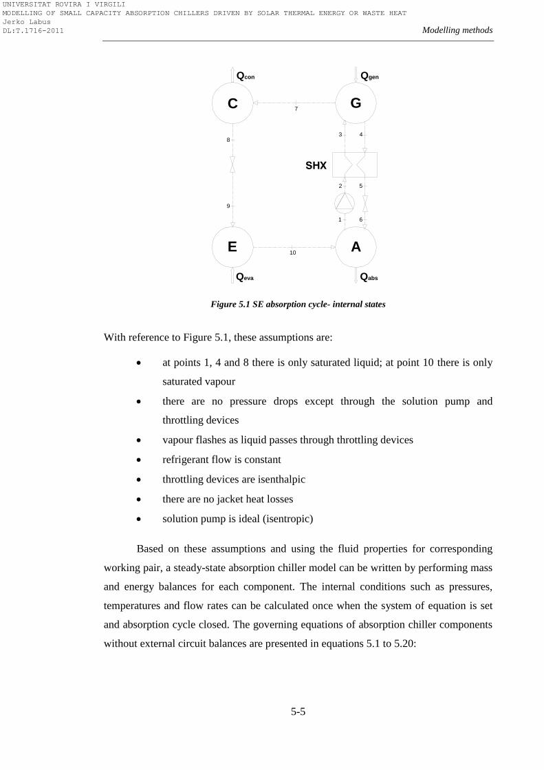
Modelling methods
5-5
Figure 5.1 SE absorption cycle- internal states
With reference to Figure 5.1, these assumptions are:
at points 1, 4 and 8 there is only saturated liquid; at point 10 there is only
saturated vapour
there are no pressure drops except through the solution pump and
throttling devices
vapour flashes as liquid passes through throttling devices
refrigerant flow is constant
throttling devices are isenthalpic
there are no jacket heat losses
solution pump is ideal (isentropic)
Based on these assumptions and using the fluid properties for corresponding
working pair, a steady-state absorption chiller model can be written by performing mass
and energy balances for each component. The internal conditions such as pressures,
temperatures and flow rates can be calculated once when the system of equation is set
and absorption cycle closed. The governing equations of absorption chiller components
without external circuit balances are presented in equations 5.1 to 5.20:
Qcon
SHX
E A
Qeva
C G
Qgen
Qabs
1
10
2 5
6
3 48
9
7
UNIVERSITAT ROVIRA I VIRGILI MODELLING OF SMALL CAPACITY ABSORPTION CHILLERS DRIVEN BY SOLAR THERMAL ENERGY OR WASTE HEAT Jerko Labus DL:T.1716-2011
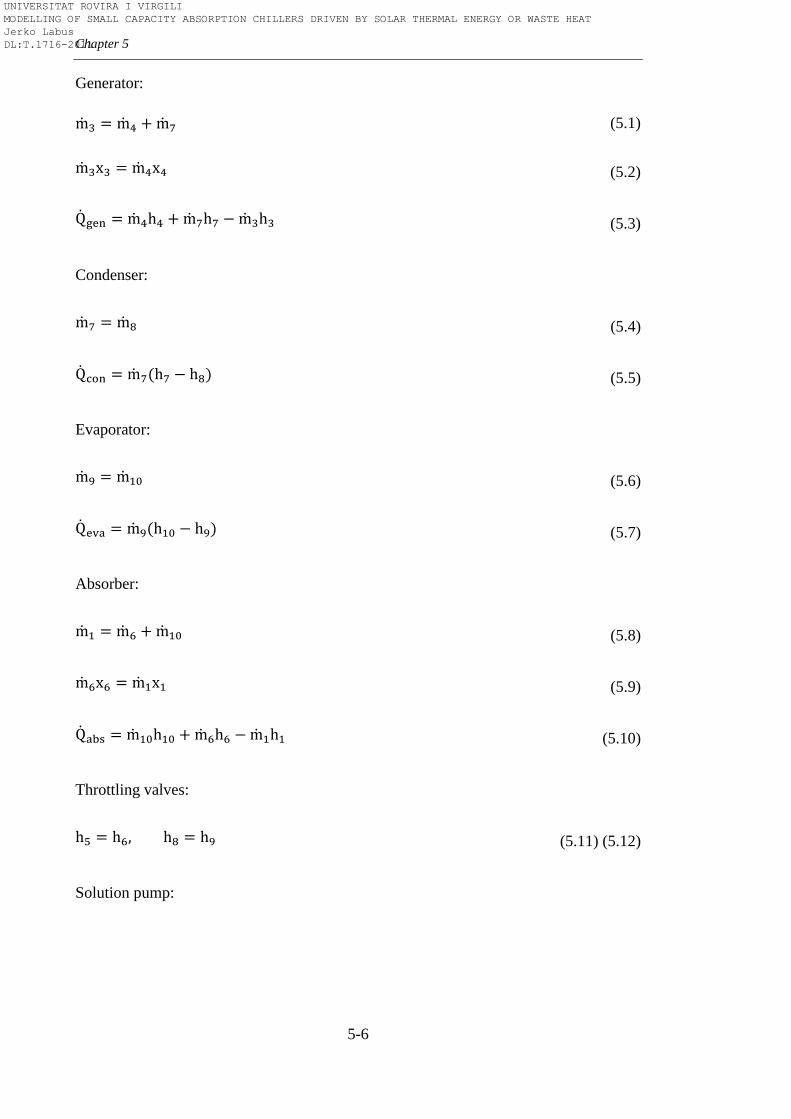
Chapter 5
5-6
Generator:
(5.1)
(5.2)
(5.3)
Condenser:
(5.4)
(5.5)
Evaporator:
(5.6)
(5.7)
Absorber:
(5.8)
(5.9)
(5.10)
Throttling valves:
(5.11) (5.12)
Solution pump:
UNIVERSITAT ROVIRA I VIRGILI MODELLING OF SMALL CAPACITY ABSORPTION CHILLERS DRIVEN BY SOLAR THERMAL ENERGY OR WASTE HEAT Jerko Labus DL:T.1716-2011
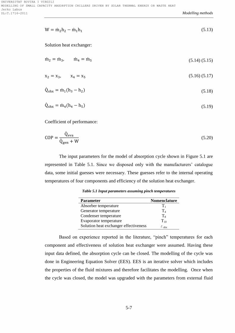
Modelling methods
5-7
(5.13)
Solution heat exchanger:
(5.14) (5.15)
(5.16) (5.17)
(5.18)
(5.19)
Coefficient of performance:
(5.20)
The input parameters for the model of absorption cycle shown in Figure 5.1 are
represented in Table 5.1. Since we disposed only with the manufacturers’ catalogue
data, some initial guesses were necessary. These guesses refer to the internal operating
temperatures of four components and efficiency of the solution heat exchanger.
Table 5.1 Input parameters assuming pinch temperatures
Parameter Nomenclature
Absorber temperature T1
Generator temperature T4
Condenser temperature T8
Evaporator temperature T10
Solution heat exchanger effectiveness eshx
Based on experience reported in the literature, ―pinch‖ temperatures for each
component and effectiveness of solution heat exchanger were assumed. Having these
input data defined, the absorption cycle can be closed. The modelling of the cycle was
done in Engineering Equation Solver (EES). EES is an iterative solver which includes
the properties of the fluid mixtures and therefore facilitates the modelling. Once when
the cycle was closed, the model was upgraded with the parameters from external fluid
UNIVERSITAT ROVIRA I VIRGILI MODELLING OF SMALL CAPACITY ABSORPTION CHILLERS DRIVEN BY SOLAR THERMAL ENERGY OR WASTE HEAT Jerko Labus DL:T.1716-2011
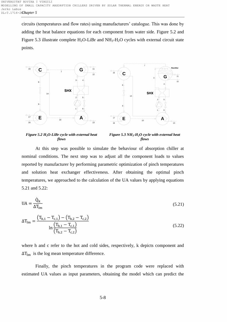
Chapter 5
5-8
circuits (temperatures and flow rates) using manufacturers’ catalogue. This was done by
adding the heat balance equations for each component from water side. Figure 5.2 and
Figure 5.3 illustrate complete H2O-LiBr and NH3-H2O cycles with external circuit state
points.
Figure 5.2 H2O-LiBr cycle with external heat
flows
Figure 5.3 NH3-H2O cycle with external heat
flows
At this step was possible to simulate the behaviour of absorption chiller at
nominal conditions. The next step was to adjust all the component loads to values
reported by manufacturer by performing parametric optimization of pinch temperatures
and solution heat exchanger effectiveness. After obtaining the optimal pinch
temperatures, we approached to the calculation of the UA values by applying equations
5.21 and 5.22:
(5.21)
(5.22)
where h and c refer to the hot and cold sides, respectively, k depicts component and
is the log mean temperature difference.
Finally, the pinch temperatures in the program code were replaced with
estimated UA values as input parameters, obtaining the model which can predict the
SHX
E A
C G
1
10
2 5
6
3 48
9
7
14
17
16
15
13
12
11
SHX
E A
C
1
10
2 5
6
48
9
14
17
16
15
13
12
11
7
3 G
Rectifier
UNIVERSITAT ROVIRA I VIRGILI MODELLING OF SMALL CAPACITY ABSORPTION CHILLERS DRIVEN BY SOLAR THERMAL ENERGY OR WASTE HEAT Jerko Labus DL:T.1716-2011
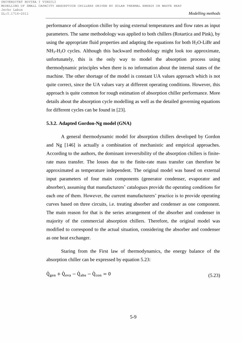
Modelling methods
5-9
performance of absorption chiller by using external temperatures and flow rates as input
parameters. The same methodology was applied to both chillers (Rotartica and Pink), by
using the appropriate fluid properties and adapting the equations for both H2O-LiBr and
NH3-H2O cycles. Although this backward methodology might look too approximate,
unfortunately, this is the only way to model the absorption process using
thermodynamic principles when there is no information about the internal states of the
machine. The other shortage of the model is constant UA values approach which is not
quite correct, since the UA values vary at different operating conditions. However, this
approach is quite common for rough estimation of absorption chiller performance. More
details about the absorption cycle modelling as well as the detailed governing equations
for different cycles can be found in [23].
5.3.2. Adapted Gordon-Ng model (GNA)
A general thermodynamic model for absorption chillers developed by Gordon
and Ng [146] is actually a combination of mechanistic and empirical approaches.
According to the authors, the dominant irreversibility of the absorption chillers is finite-
rate mass transfer. The losses due to the finite-rate mass transfer can therefore be
approximated as temperature independent. The original model was based on external
input parameters of four main components (generator condenser, evaporator and
absorber), assuming that manufacturers’ catalogues provide the operating conditions for
each one of them. However, the current manufacturers’ practice is to provide operating
curves based on three circuits, i.e. treating absorber and condenser as one component.
The main reason for that is the series arrangement of the absorber and condenser in
majority of the commercial absorption chillers. Therefore, the original model was
modified to correspond to the actual situation, considering the absorber and condenser
as one heat exchanger.
Staring from the First law of thermodynamics, the energy balance of the
absorption chiller can be expressed by equation 5.23:
(5.23)
UNIVERSITAT ROVIRA I VIRGILI MODELLING OF SMALL CAPACITY ABSORPTION CHILLERS DRIVEN BY SOLAR THERMAL ENERGY OR WASTE HEAT Jerko Labus DL:T.1716-2011
Chapter 5
5-10
Since the absorber and condenser are treated as one component, equation 5.23
can be rearranged to:
(5.24)
The entropy balance which takes into account the dominant irreversibility can be
approximated by equation 5.25:
(5.25)
Here, denotes losses from all sources other than finite-rate heat transfer.
The heat transfer process was approximated as isothermal, due to the common practice
in heat exchangers to adopt process-averaged values for absolute temperatures
. Rearranging the equation 5.25 and expressing in terms of yields
(5.26)
Inserting equation 5.26 into equation 5.24 yields
(5.27)
Now, by solving equation 5.27 for , it can be obtained
(5.28)
By introducing the COP and dividing both sides of equation 5.28 by
(5.29)
UNIVERSITAT ROVIRA I VIRGILI MODELLING OF SMALL CAPACITY ABSORPTION CHILLERS DRIVEN BY SOLAR THERMAL ENERGY OR WASTE HEAT Jerko Labus DL:T.1716-2011
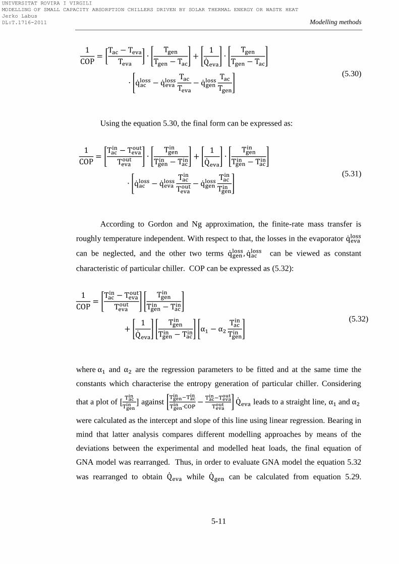
Modelling methods
5-11
(5.30)
Using the equation 5.30, the final form can be expressed as:
(5.31)
According to Gordon and Ng approximation, the finite-rate mass transfer is
roughly temperature independent. With respect to that, the losses in the evaporator
can be neglected, and the other two terms
can be viewed as constant
characteristic of particular chiller. COP can be expressed as (5.32):
(5.32)
where and are the regression parameters to be fitted and at the same time the
constants which characterise the entropy generation of particular chiller. Considering
that a plot of
against
leads to a straight line, and
were calculated as the intercept and slope of this line using linear regression. Bearing in
mind that latter analysis compares different modelling approaches by means of the
deviations between the experimental and modelled heat loads, the final equation of
GNA model was rearranged. Thus, in order to evaluate GNA model the equation 5.32
was rearranged to obtain while can be calculated from equation 5.29.
UNIVERSITAT ROVIRA I VIRGILI MODELLING OF SMALL CAPACITY ABSORPTION CHILLERS DRIVEN BY SOLAR THERMAL ENERGY OR WASTE HEAT Jerko Labus DL:T.1716-2011
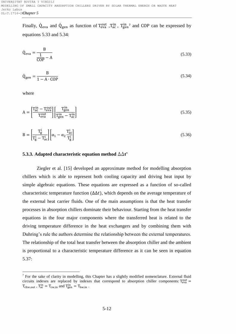
Chapter 5
5-12
Finally, and as function of
,
, 7 and can be expressed by
equations 5.33 and 5.34:
(5.33)
(5.34)
where
(5.35)
(5.36)
5.3.3. Adapted characteristic equation method DDt’
Ziegler et al. [15] developed an approximate method for modelling absorption
chillers which is able to represent both cooling capacity and driving heat input by
simple algebraic equations. These equations are expressed as a function of so-called
characteristic temperature function ( , which depends on the average temperature of
the external heat carrier fluids. One of the main assumptions is that the heat transfer
processes in absorption chillers dominate their behaviour. Starting from the heat transfer
equations in the four major components where the transferred heat is related to the
driving temperature difference in the heat exchangers and by combining them with
Duhring’s rule the authors determine the relationship between the external temperatures.
The relationship of the total heat transfer between the absorption chiller and the ambient
is proportional to a characteristic temperature difference as it can be seen in equation
5.37:
7 For the sake of clarity in modelling, this Chapter has a slightly modified nomenclature. External fluid
circuits indexes are replaced by indexes that correspond to absorption chiller components:
, and
.
UNIVERSITAT ROVIRA I VIRGILI MODELLING OF SMALL CAPACITY ABSORPTION CHILLERS DRIVEN BY SOLAR THERMAL ENERGY OR WASTE HEAT Jerko Labus DL:T.1716-2011
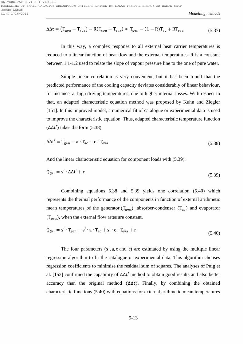
Modelling methods
5-13
(5.37)
In this way, a complex response to all external heat carrier temperatures is
reduced to a linear function of heat flow and the external temperatures. R is a constant
between 1.1-1.2 used to relate the slope of vapour pressure line to the one of pure water.
Simple linear correlation is very convenient, but it has been found that the
predicted performance of the cooling capacity deviates considerably of linear behaviour,
for instance, at high driving temperatures, due to higher internal losses. With respect to
that, an adapted characteristic equation method was proposed by Kuhn and Ziegler
[151]. In this improved model, a numerical fit of catalogue or experimental data is used
to improve the characteristic equation. Thus, adapted characteristic temperature function
( takes the form (5.38):
(5.38)
And the linear characteristic equation for component loads with (5.39):
(5.39)
Combining equations 5.38 and 5.39 yields one correlation (5.40) which
represents the thermal performance of the components in function of external arithmetic
mean temperatures of the generator , absorber-condenser and evaporator
, when the external flow rates are constant.
(5.40)
The four parameters ( and ) are estimated by using the multiple linear
regression algorithm to fit the catalogue or experimental data. This algorithm chooses
regression coefficients to minimise the residual sum of squares. The analyses of Puig et
al. [152] confirmed the capability of method to obtain good results and also better
accuracy than the original method . Finally, by combining the obtained
characteristic functions (5.40) with equations for external arithmetic mean temperatures
UNIVERSITAT ROVIRA I VIRGILI MODELLING OF SMALL CAPACITY ABSORPTION CHILLERS DRIVEN BY SOLAR THERMAL ENERGY OR WASTE HEAT Jerko Labus DL:T.1716-2011
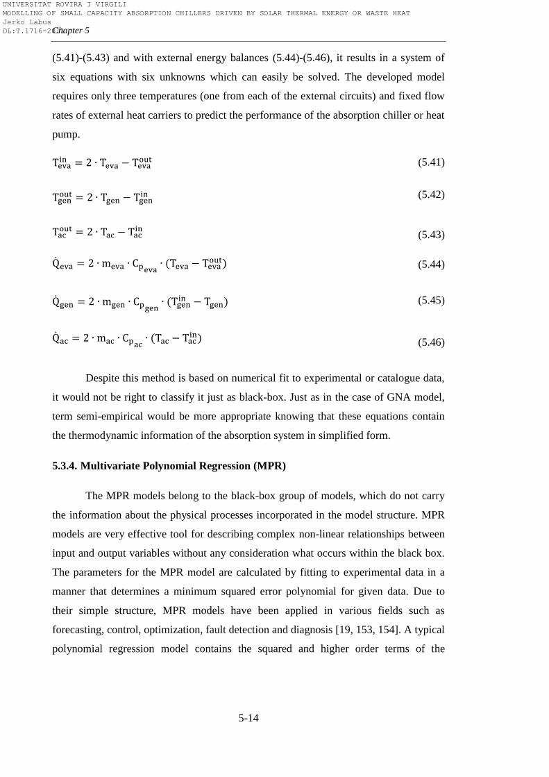
Chapter 5
5-14
(5.41)-(5.43) and with external energy balances (5.44)-(5.46), it results in a system of
six equations with six unknowns which can easily be solved. The developed model
requires only three temperatures (one from each of the external circuits) and fixed flow
rates of external heat carriers to predict the performance of the absorption chiller or heat
pump.
(5.41)
(5.42)
(5.43)
(5.44)
(5.45)
(5.46)
Despite this method is based on numerical fit to experimental or catalogue data,
it would not be right to classify it just as black-box. Just as in the case of GNA model,
term semi-empirical would be more appropriate knowing that these equations contain
the thermodynamic information of the absorption system in simplified form.
5.3.4. Multivariate Polynomial Regression (MPR)
The MPR models belong to the black-box group of models, which do not carry
the information about the physical processes incorporated in the model structure. MPR
models are very effective tool for describing complex non-linear relationships between
input and output variables without any consideration what occurs within the black box.
The parameters for the MPR model are calculated by fitting to experimental data in a
manner that determines a minimum squared error polynomial for given data. Due to
their simple structure, MPR models have been applied in various fields such as
forecasting, control, optimization, fault detection and diagnosis [19, 153, 154]. A typical
polynomial regression model contains the squared and higher order terms of the
UNIVERSITAT ROVIRA I VIRGILI MODELLING OF SMALL CAPACITY ABSORPTION CHILLERS DRIVEN BY SOLAR THERMAL ENERGY OR WASTE HEAT Jerko Labus DL:T.1716-2011
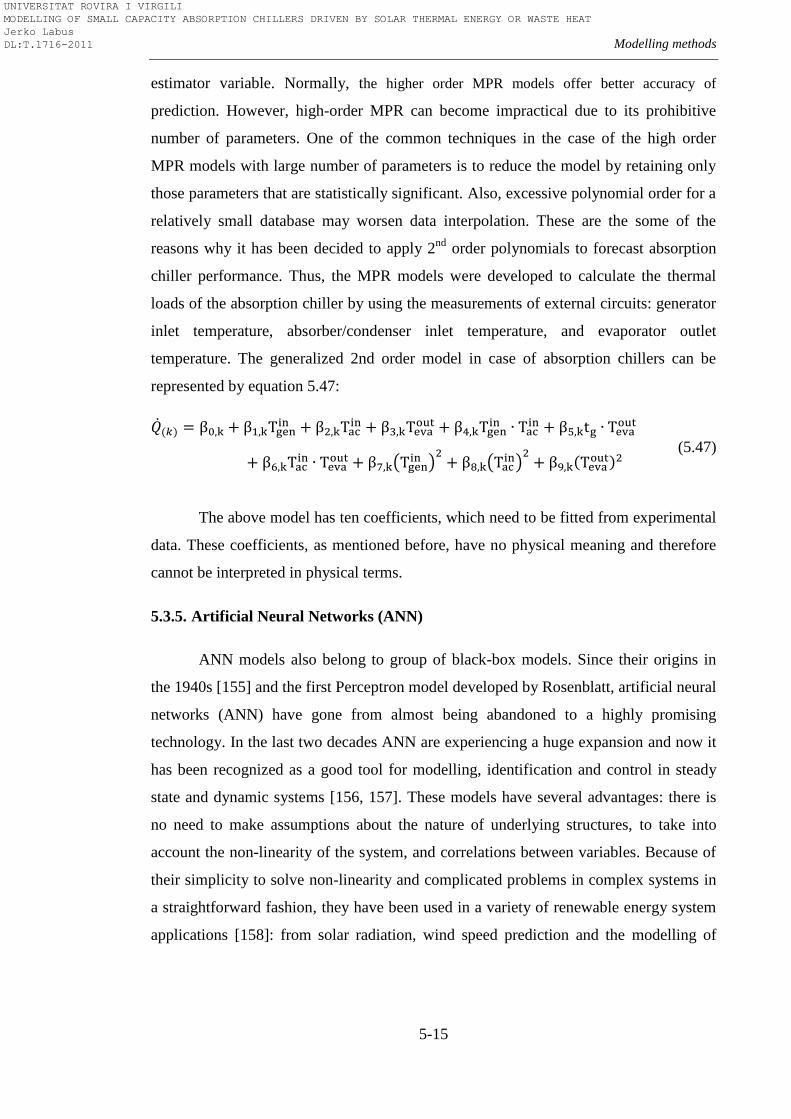
Modelling methods
5-15
estimator variable. Normally, the higher order MPR models offer better accuracy of
prediction. However, high-order MPR can become impractical due to its prohibitive
number of parameters. One of the common techniques in the case of the high order
MPR models with large number of parameters is to reduce the model by retaining only
those parameters that are statistically significant. Also, excessive polynomial order for a
relatively small database may worsen data interpolation. These are the some of the
reasons why it has been decided to apply 2nd
order polynomials to forecast absorption
chiller performance. Thus, the MPR models were developed to calculate the thermal
loads of the absorption chiller by using the measurements of external circuits: generator
inlet temperature, absorber/condenser inlet temperature, and evaporator outlet
temperature. The generalized 2nd order model in case of absorption chillers can be
represented by equation 5.47:
(5.47)
The above model has ten coefficients, which need to be fitted from experimental
data. These coefficients, as mentioned before, have no physical meaning and therefore
cannot be interpreted in physical terms.
5.3.5. Artificial Neural Networks (ANN)
ANN models also belong to group of black-box models. Since their origins in
the 1940s [155] and the first Perceptron model developed by Rosenblatt, artificial neural
networks (ANN) have gone from almost being abandoned to a highly promising
technology. In the last two decades ANN are experiencing a huge expansion and now it
has been recognized as a good tool for modelling, identification and control in steady
state and dynamic systems [156, 157]. These models have several advantages: there is
no need to make assumptions about the nature of underlying structures, to take into
account the non-linearity of the system, and correlations between variables. Because of
their simplicity to solve non-linearity and complicated problems in complex systems in
a straightforward fashion, they have been used in a variety of renewable energy system
applications [158]: from solar radiation, wind speed prediction and the modelling of
UNIVERSITAT ROVIRA I VIRGILI MODELLING OF SMALL CAPACITY ABSORPTION CHILLERS DRIVEN BY SOLAR THERMAL ENERGY OR WASTE HEAT Jerko Labus DL:T.1716-2011
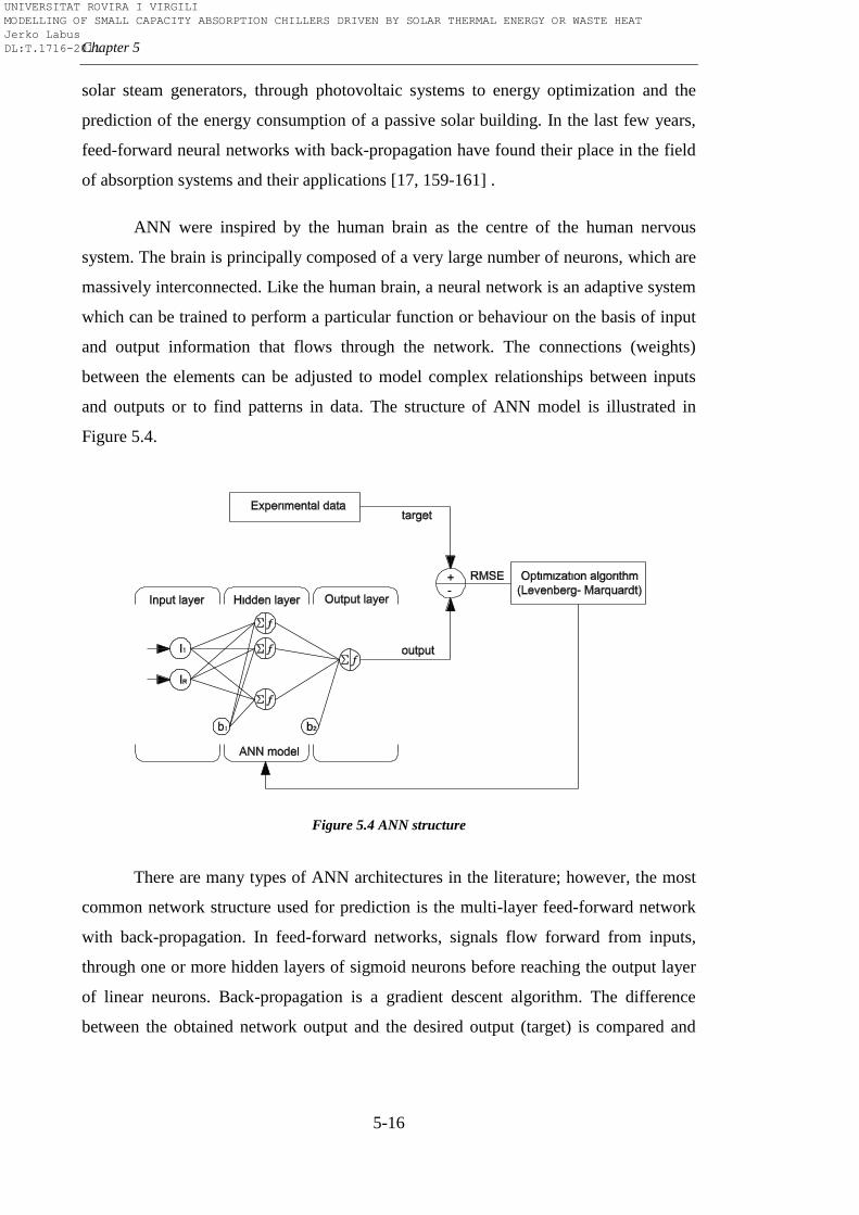
Chapter 5
5-16
solar steam generators, through photovoltaic systems to energy optimization and the
prediction of the energy consumption of a passive solar building. In the last few years,
feed-forward neural networks with back-propagation have found their place in the field
of absorption systems and their applications [17, 159-161] .
ANN were inspired by the human brain as the centre of the human nervous
system. The brain is principally composed of a very large number of neurons, which are
massively interconnected. Like the human brain, a neural network is an adaptive system
which can be trained to perform a particular function or behaviour on the basis of input
and output information that flows through the network. The connections (weights)
between the elements can be adjusted to model complex relationships between inputs
and outputs or to find patterns in data. The structure of ANN model is illustrated in
Figure 5.4.
Figure 5.4 ANN structure
There are many types of ANN architectures in the literature; however, the most
common network structure used for prediction is the multi-layer feed-forward network
with back-propagation. In feed-forward networks, signals flow forward from inputs,
through one or more hidden layers of sigmoid neurons before reaching the output layer
of linear neurons. Back-propagation is a gradient descent algorithm. The difference
between the obtained network output and the desired output (target) is compared and
UNIVERSITAT ROVIRA I VIRGILI MODELLING OF SMALL CAPACITY ABSORPTION CHILLERS DRIVEN BY SOLAR THERMAL ENERGY OR WASTE HEAT Jerko Labus DL:T.1716-2011
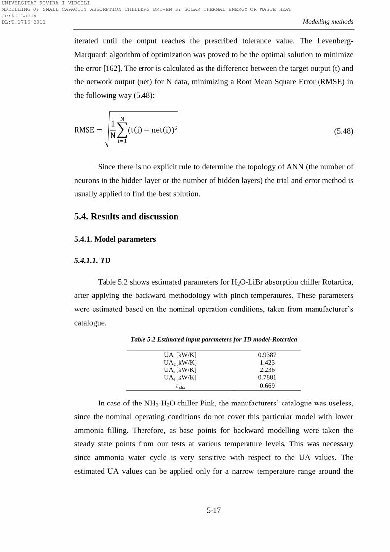
Modelling methods
5-17
iterated until the output reaches the prescribed tolerance value. The Levenberg-
Marquardt algorithm of optimization was proved to be the optimal solution to minimize
the error [162]. The error is calculated as the difference between the target output (t) and
the network output (net) for N data, minimizing a Root Mean Square Error (RMSE) in
the following way (5.48):
(5.48)
Since there is no explicit rule to determine the topology of ANN (the number of
neurons in the hidden layer or the number of hidden layers) the trial and error method is
usually applied to find the best solution.
5.4. Results and discussion
5.4.1. Model parameters
5.4.1.1. TD
Table 5.2 shows estimated parameters for H2O-LiBr absorption chiller Rotartica,
after applying the backward methodology with pinch temperatures. These parameters
were estimated based on the nominal operation conditions, taken from manufacturer’s
catalogue.
Table 5.2 Estimated input parameters for TD model-Rotartica
UAc [kW/K] 0.9387
UAg [kW/K] 1.423
UAa [kW/K] 2.236
UAe [kW/K] 0.7881
eshx 0.669
In case of the NH3-H2O chiller Pink, the manufacturers’ catalogue was useless,
since the nominal operating conditions do not cover this particular model with lower
ammonia filling. Therefore, as base points for backward modelling were taken the
steady state points from our tests at various temperature levels. This was necessary
since ammonia water cycle is very sensitive with respect to the UA values. The
estimated UA values can be applied only for a narrow temperature range around the
UNIVERSITAT ROVIRA I VIRGILI MODELLING OF SMALL CAPACITY ABSORPTION CHILLERS DRIVEN BY SOLAR THERMAL ENERGY OR WASTE HEAT Jerko Labus DL:T.1716-2011
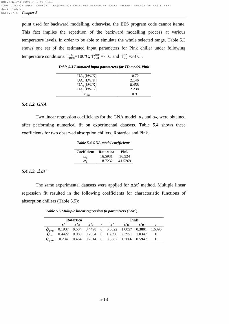
Chapter 5
5-18
point used for backward modelling, otherwise, the EES program code cannot iterate.
This fact implies the repetition of the backward modelling process at various
temperature levels, in order to be able to simulate the whole selected range. Table 5.3
shows one set of the estimated input parameters for Pink chiller under following
temperature conditions: =100ºC,
=7 ºC and =33ºC .
Table 5.3 Estimated input parameters for TD model-Pink
UAc [kW/K] 10.72
UAg [kW/K] 2.146
UAa [kW/K] 8.458
UAe [kW/K] 2.238
eshx 0.9
5.4.1.2. GNA
Two linear regression coefficients for the GNA model, and were obtained
after performing numerical fit on experimental datasets. Table 5.4 shows these
coefficients for two observed absorption chillers, Rotartica and Pink.
Table 5.4 GNA model coefficients
Coefficient Rotartica Pink
16.5931 36.524
18.7232 41.5269
5.4.1.3. DDt’
The same experimental datasets were applied for method. Multiple linear
regression fit resulted in the following coefficients for characteristic functions of
absorption chillers (Table 5.5):
Table 5.5 Multiple linear regression fit parameters
Rotartica Pink
0.1937 0.504 0.4498 0 0.6822 1.0057 0.3801 1.6396
0.4422 0.989 0.7084 0 1.2698 2.3951 1.0347 0
0.234 0.464 0.2614 0 0.5662 1.3066 0.5947 0
UNIVERSITAT ROVIRA I VIRGILI MODELLING OF SMALL CAPACITY ABSORPTION CHILLERS DRIVEN BY SOLAR THERMAL ENERGY OR WASTE HEAT Jerko Labus DL:T.1716-2011
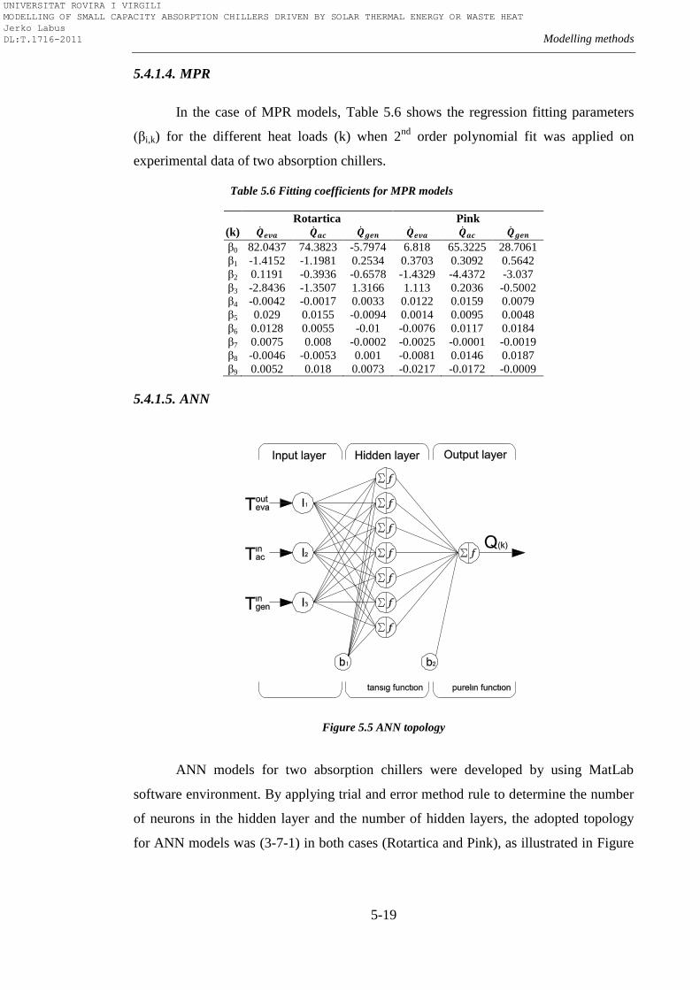
Modelling methods
5-19
5.4.1.4. MPR
In the case of MPR models, Table 5.6 shows the regression fitting parameters
(βi,k) for the different heat loads (k) when 2nd
order polynomial fit was applied on
experimental data of two absorption chillers.
Table 5.6 Fitting coefficients for MPR models
Rotartica Pink
(k)
β0 82.0437 74.3823 -5.7974 6.818 65.3225 28.7061
β1 -1.4152 -1.1981 0.2534 0.3703 0.3092 0.5642
β2 0.1191 -0.3936 -0.6578 -1.4329 -4.4372 -3.037
β3 -2.8436 -1.3507 1.3166 1.113 0.2036 -0.5002
β4 -0.0042 -0.0017 0.0033 0.0122 0.0159 0.0079
β5 0.029 0.0155 -0.0094 0.0014 0.0095 0.0048
β6 0.0128 0.0055 -0.01 -0.0076 0.0117 0.0184
β7 0.0075 0.008 -0.0002 -0.0025 -0.0001 -0.0019
β8 -0.0046 -0.0053 0.001 -0.0081 0.0146 0.0187
β9 0.0052 0.018 0.0073 -0.0217 -0.0172 -0.0009
5.4.1.5. ANN
Figure 5.5 ANN topology
ANN models for two absorption chillers were developed by using MatLab
software environment. By applying trial and error method rule to determine the number
of neurons in the hidden layer and the number of hidden layers, the adopted topology
for ANN models was (3-7-1) in both cases (Rotartica and Pink), as illustrated in Figure
UNIVERSITAT ROVIRA I VIRGILI MODELLING OF SMALL CAPACITY ABSORPTION CHILLERS DRIVEN BY SOLAR THERMAL ENERGY OR WASTE HEAT Jerko Labus DL:T.1716-2011
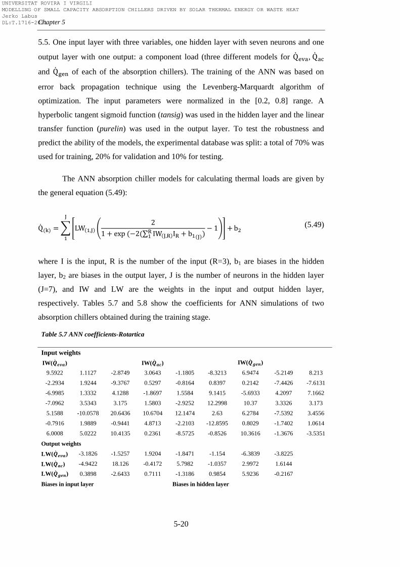
Chapter 5
5-20
5.5. One input layer with three variables, one hidden layer with seven neurons and one
output layer with one output: a component load (three different models for ,
and of each of the absorption chillers). The training of the ANN was based on
error back propagation technique using the Levenberg-Marquardt algorithm of
optimization. The input parameters were normalized in the [0.2, 0.8] range. A
hyperbolic tangent sigmoid function (tansig) was used in the hidden layer and the linear
transfer function (purelin) was used in the output layer. To test the robustness and
predict the ability of the models, the experimental database was split: a total of 70% was
used for training, 20% for validation and 10% for testing.
The ANN absorption chiller models for calculating thermal loads are given by
the general equation (5.49):
(5.49)
where I is the input, R is the number of the input (R=3), b1 are biases in the hidden
layer, b2 are biases in the output layer, J is the number of neurons in the hidden layer
(J=7), and IW and LW are the weights in the input and output hidden layer,
respectively. Tables 5.7 and 5.8 show the coefficients for ANN simulations of two
absorption chillers obtained during the training stage.
Table 5.7 ANN coefficients-Rotartica
Input weights
IW( )
IW( )
IW( )
9.5922 1.1127 -2.8749 3.0643 -1.1805 -8.3213 6.9474 -5.2149 8.213
-2.2934 1.9244 -9.3767 0.5297 -0.8164 0.8397 0.2142 -7.4426 -7.6131
-6.9985 1.3332 4.1288 -1.8697 1.5584 9.1415 -5.6933 4.2097 7.1662
-7.0962 3.5343 3.175 1.5803 -2.9252 12.2998 10.37 3.3326 3.173
5.1588 -10.0578 20.6436 10.6704 12.1474 2.63 6.2784 -7.5392 3.4556
-0.7916 1.9889 -0.9441 4.8713 -2.2103 -12.8595 0.8029 -1.7402 1.0614
6.0008 5.0222 10.4135 0.2361 -8.5725 -0.8526 10.3616 -1.3676 -3.5351
Output weights
LW( ) -3.1826 -1.5257 1.9204 -1.8471 -1.154 -6.3839 -3.8225
LW( ) -4.9422 18.126 -0.4172 5.7982 -1.0357 2.9972 1.6144
LW( ) 0.3898 -2.6433 0.7111 -1.3186 0.9854 5.9236 -0.2167
Biases in input layer Biases in hidden layer
UNIVERSITAT ROVIRA I VIRGILI MODELLING OF SMALL CAPACITY ABSORPTION CHILLERS DRIVEN BY SOLAR THERMAL ENERGY OR WASTE HEAT Jerko Labus DL:T.1716-2011
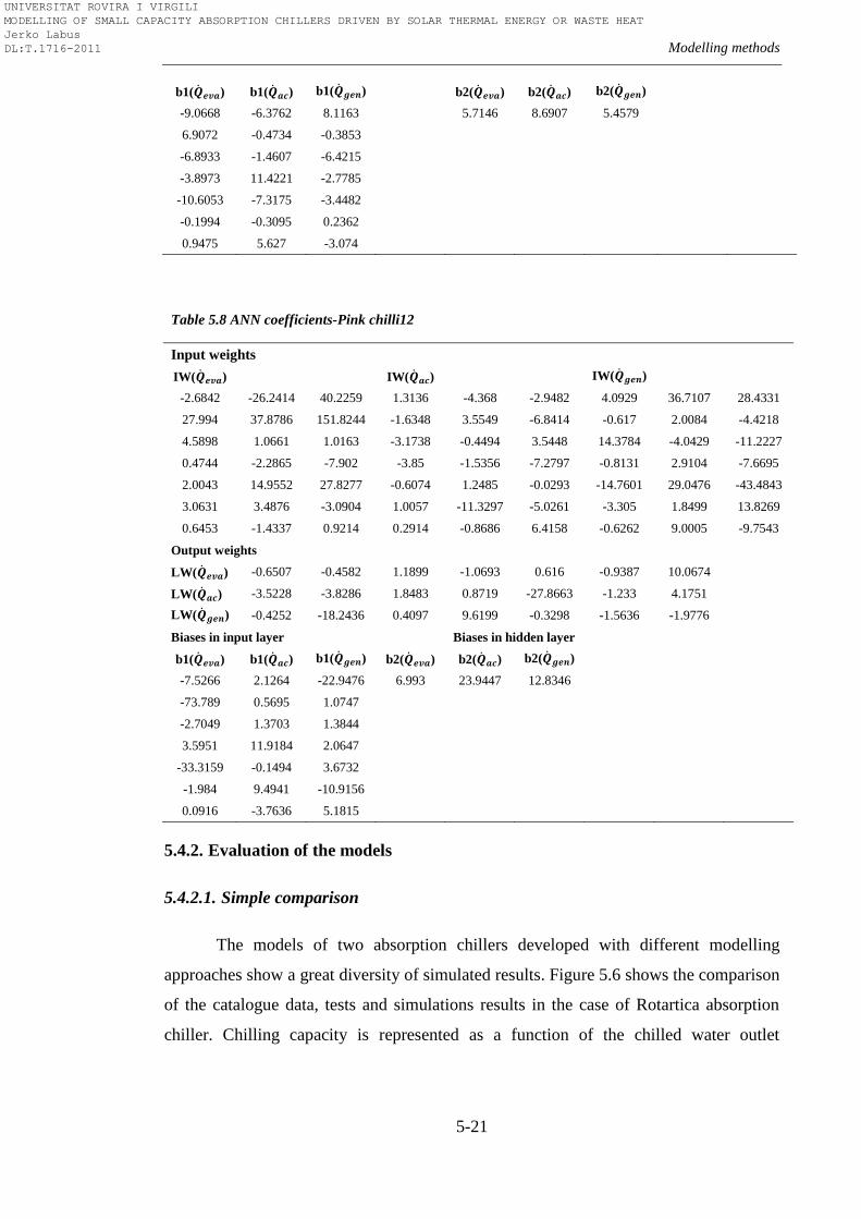
Modelling methods
5-21
b1( ) b1( ) b1( )
b2( ) b2( ) b2( )
-9.0668 -6.3762 8.1163
5.7146 8.6907 5.4579
6.9072 -0.4734 -0.3853
-6.8933 -1.4607 -6.4215
-3.8973 11.4221 -2.7785
-10.6053 -7.3175 -3.4482
-0.1994 -0.3095 0.2362
0.9475 5.627 -3.074
Table 5.8 ANN coefficients-Pink chilli12
Input weights
IW( )
IW( )
IW( )
-2.6842 -26.2414 40.2259 1.3136 -4.368 -2.9482 4.0929 36.7107 28.4331
27.994 37.8786 151.8244 -1.6348 3.5549 -6.8414 -0.617 2.0084 -4.4218
4.5898 1.0661 1.0163 -3.1738 -0.4494 3.5448 14.3784 -4.0429 -11.2227
0.4744 -2.2865 -7.902 -3.85 -1.5356 -7.2797 -0.8131 2.9104 -7.6695
2.0043 14.9552 27.8277 -0.6074 1.2485 -0.0293 -14.7601 29.0476 -43.4843
3.0631 3.4876 -3.0904 1.0057 -11.3297 -5.0261 -3.305 1.8499 13.8269
0.6453 -1.4337 0.9214 0.2914 -0.8686 6.4158 -0.6262 9.0005 -9.7543
Output weights
LW( ) -0.6507 -0.4582 1.1899 -1.0693 0.616 -0.9387 10.0674
LW( ) -3.5228 -3.8286 1.8483 0.8719 -27.8663 -1.233 4.1751
LW( ) -0.4252 -18.2436 0.4097 9.6199 -0.3298 -1.5636 -1.9776
Biases in input layer Biases in hidden layer
b1( ) b1( ) b1( ) b2( ) b2( ) b2( )
-7.5266 2.1264 -22.9476 6.993 23.9447 12.8346
-73.789 0.5695 1.0747
-2.7049 1.3703 1.3844
3.5951 11.9184 2.0647
-33.3159 -0.1494 3.6732
-1.984 9.4941 -10.9156
0.0916 -3.7636 5.1815
5.4.2. Evaluation of the models
5.4.2.1. Simple comparison
The models of two absorption chillers developed with different modelling
approaches show a great diversity of simulated results. Figure 5.6 shows the comparison
of the catalogue data, tests and simulations results in the case of Rotartica absorption
chiller. Chilling capacity is represented as a function of the chilled water outlet
UNIVERSITAT ROVIRA I VIRGILI MODELLING OF SMALL CAPACITY ABSORPTION CHILLERS DRIVEN BY SOLAR THERMAL ENERGY OR WASTE HEAT Jerko Labus DL:T.1716-2011
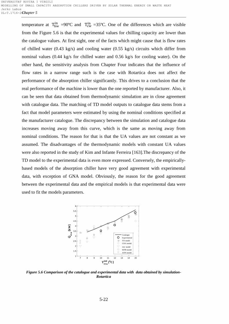
Chapter 5
5-22
temperature at =90ºC and
=35ºC. One of the differences which are visible
from the Figure 5.6 is that the experimental values for chilling capacity are lower than
the catalogue values. At first sight, one of the facts which might cause that is flow rates
of chilled water (0.43 kg/s) and cooling water (0.55 kg/s) circuits which differ from
nominal values (0.44 kg/s for chilled water and 0.56 kg/s for cooling water). On the
other hand, the sensitivity analysis from Chapter Four indicates that the influence of
flow rates in a narrow range such is the case with Rotartica does not affect the
performance of the absorption chiller significantly. This drives to a conclusion that the
real performance of the machine is lower than the one reported by manufacturer. Also, it
can be seen that data obtained from thermodynamic simulation are in close agreement
with catalogue data. The matching of TD model outputs to catalogue data stems from a
fact that model parameters were estimated by using the nominal conditions specified at
the manufacturer catalogue. The discrepancy between the simulation and catalogue data
increases moving away from this curve, which is the same as moving away from
nominal conditions. The reason for that is that the UA values are not constant as we
assumed. The disadvantages of the thermodynamic models with constant UA values
were also reported in the study of Kim and Infante Ferreira [163].The discrepancy of the
TD model to the experimental data is even more expressed. Conversely, the empirically-
based models of the absorption chiller have very good agreement with experimental
data, with exception of GNA model. Obviously, the reason for the good agreement
between the experimental data and the empirical models is that experimental data were
used to fit the models parameters.
Figure 5.6 Comparison of the catalogue and experimental data with data obtained by simulation-
Rotartica
7 8 9 10 11 12 13 14 151
1.5
2
2.5
3
3.5
4
4.5
5
5.5
6
Teva
out [
oC]
Qev
a [
kW
]
Catalogue
Experimental
TD model
GNA model
t, model
MPR model
ANN model
.
UNIVERSITAT ROVIRA I VIRGILI MODELLING OF SMALL CAPACITY ABSORPTION CHILLERS DRIVEN BY SOLAR THERMAL ENERGY OR WASTE HEAT Jerko Labus DL:T.1716-2011
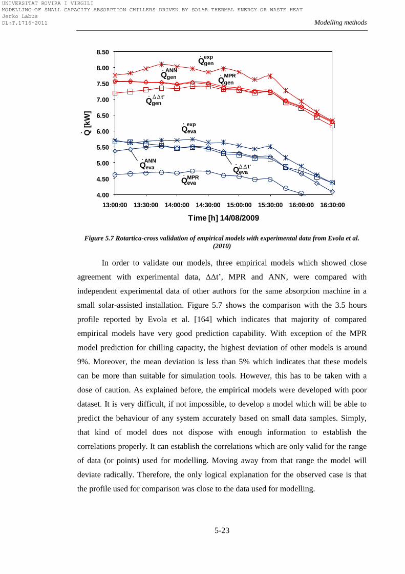
Modelling methods
5-23
Figure 5.7 Rotartica-cross validation of empirical models with experimental data from Evola et al.
(2010)
In order to validate our models, three empirical models which showed close
agreement with experimental data, ΔΔt’, MPR and ANN, were compared with
independent experimental data of other authors for the same absorption machine in a
small solar-assisted installation. Figure 5.7 shows the comparison with the 3.5 hours
profile reported by Evola et al. [164] which indicates that majority of compared
empirical models have very good prediction capability. With exception of the MPR
model prediction for chilling capacity, the highest deviation of other models is around
9%. Moreover, the mean deviation is less than 5% which indicates that these models
can be more than suitable for simulation tools. However, this has to be taken with a
dose of caution. As explained before, the empirical models were developed with poor
dataset. It is very difficult, if not impossible, to develop a model which will be able to
predict the behaviour of any system accurately based on small data samples. Simply,
that kind of model does not dispose with enough information to establish the
correlations properly. It can establish the correlations which are only valid for the range
of data (or points) used for modelling. Moving away from that range the model will
deviate radically. Therefore, the only logical explanation for the observed case is that
the profile used for comparison was close to the data used for modelling.
4.00
4.50
5.00
5.50
6.00
6.50
7.00
7.50
8.00
8.50
13:00:00 13:30:00 14:00:00 14:30:00 15:00:00 15:30:00 16:00:00 16:30:00
Q [
kW
]
Time [h] 14/08/2009
Qeva
QevaQeva
Qgen
DD t'
Qgen
exp.
. ANN
Qgen
.
Qgen
. MPR
Qeva
.
.
.
.
exp
ANNDD t'
MPR
.
UNIVERSITAT ROVIRA I VIRGILI MODELLING OF SMALL CAPACITY ABSORPTION CHILLERS DRIVEN BY SOLAR THERMAL ENERGY OR WASTE HEAT Jerko Labus DL:T.1716-2011
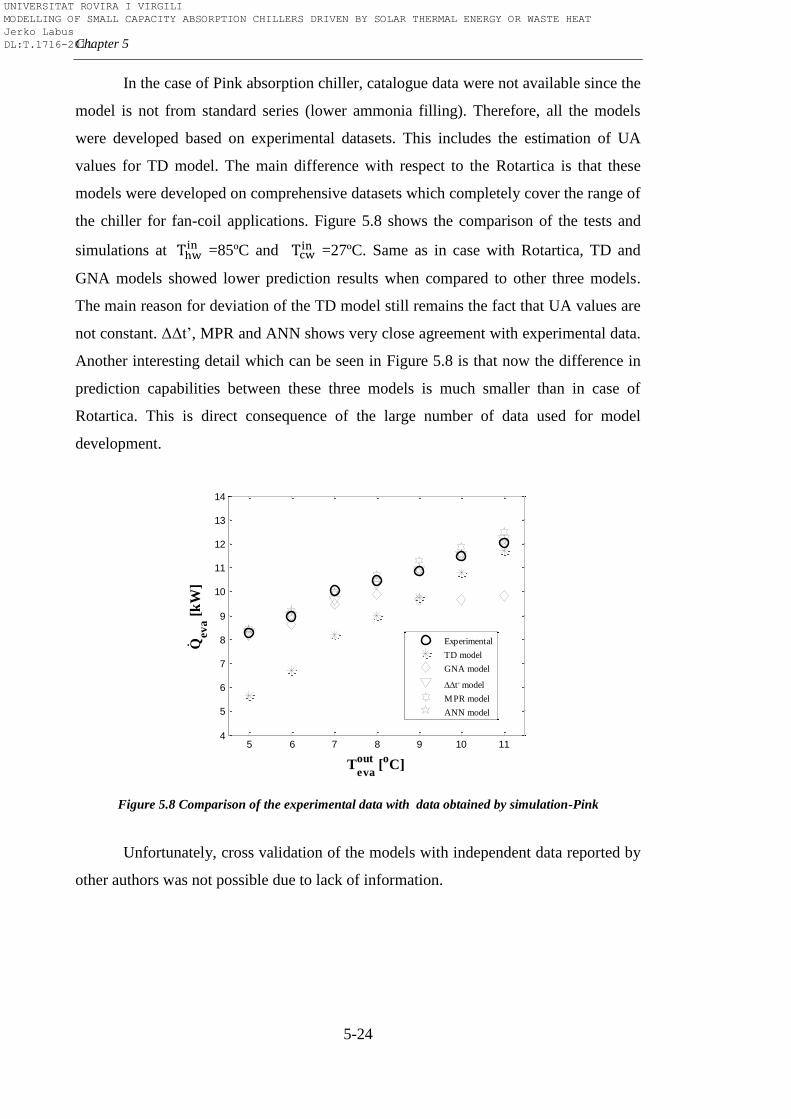
Chapter 5
5-24
In the case of Pink absorption chiller, catalogue data were not available since the
model is not from standard series (lower ammonia filling). Therefore, all the models
were developed based on experimental datasets. This includes the estimation of UA
values for TD model. The main difference with respect to the Rotartica is that these
models were developed on comprehensive datasets which completely cover the range of
the chiller for fan-coil applications. Figure 5.8 shows the comparison of the tests and
simulations at =85ºC and
=27ºC. Same as in case with Rotartica, TD and
GNA models showed lower prediction results when compared to other three models.
The main reason for deviation of the TD model still remains the fact that UA values are
not constant. ΔΔt’, MPR and ANN shows very close agreement with experimental data.
Another interesting detail which can be seen in Figure 5.8 is that now the difference in
prediction capabilities between these three models is much smaller than in case of
Rotartica. This is direct consequence of the large number of data used for model
development.
Figure 5.8 Comparison of the experimental data with data obtained by simulation-Pink
Unfortunately, cross validation of the models with independent data reported by
other authors was not possible due to lack of information.
5 6 7 8 9 10 114
5
6
7
8
9
10
11
12
13
14
Teva
out [
oC]
Qev
a [
kW
]
Experimental
TD model
GNA model
t, model
MPR model
ANN model
.
UNIVERSITAT ROVIRA I VIRGILI MODELLING OF SMALL CAPACITY ABSORPTION CHILLERS DRIVEN BY SOLAR THERMAL ENERGY OR WASTE HEAT Jerko Labus DL:T.1716-2011
Modelling methods
5-25
5.4.2.2. Statistical indicators
The goodness-of-fit of models is usually evaluated in terms of the statistical
indicators. The statistical performance analysis of different developed models was
conducted including several statistical indicators: the residual sum of squares (SSres), the
coefficient of determination (R2), the root mean square error (RMSE), the coefficient of
variation (CV), the mean absolute difference ( ), the maximum residual ( ) and the
minimum residual ( ).
The most common parameters to check how close the predicted values are to
observed data are the residual sum of squares and the coefficient of determination.
Residual is unexplained variation after fitting a model explained through the difference
between the value predicted by the model (yi) and the associated observed value (ŷi)
(5.50). The sum of the squares of these differences is called the residual sum of squares
(5.51) and can be understood as a measure of the discrepancy between the data and an
estimation model. A smaller SSres indicates better fit to the observed data.
(5.50)
(5.51)
The coefficient of determination is another parameter which quantifies the
goodness of fit. The R2 can be calculated from the residual sum of squares and the total
sum of squares (SStot) by using equation 5.52:
(5.52)
(5.53)
R2 can be interpreted as a statistical measure of how well a model prediction
approximates the observed data. An R2 of 1.0 would indicate that model prediction
UNIVERSITAT ROVIRA I VIRGILI MODELLING OF SMALL CAPACITY ABSORPTION CHILLERS DRIVEN BY SOLAR THERMAL ENERGY OR WASTE HEAT Jerko Labus DL:T.1716-2011
Chapter 5
5-26
perfectly fits the observed data. However, the statistical analysis cannot rely only on R2,
no matter how a fit is reasonable. It should be interpreted together with other model
parameters which may have values that make no sense or the confidence intervals may
be too wide.
An illustration of how close the model prediction is likely to be to the parametric
mean can be done by using confidence limits (CL), the values at the upper and lower
end of the confidence interval. Usually, the model best fit parameter values are
evaluated by using 95% confidence interval. Simplified, it means that 5% of the
predicted values are expected to fall outside the confidence limits. If the confidence
limits are reasonably narrow, it can be said that the best fit parameter values are
determined with a reasonable certainty. The 95% confidence limits can be estimated by
using the equation 5.54:
(5.54)
t* is the constant which comes from t distribution, and depends on the desired
confidence distribution and the numbers of degrees of freedom. The RMSE is statistical
indicator which measures the precision of the model and can be calculated as the square
root of the variance of the residuals (equation 5.55). RMSE indicates the absolute fit of the
model to the observed data.
(5.55)
Five different models of Rotartica absorption chiller are compared in Figure 5.9
through the predicted chilling capacity and driving heat input ( and ). R2 and
CL (in the form of dashed lines) of each model are shown as parameters that allow the
comparison of the predictive capabilities. The statistical parameters indicate that better
accuracy can be obtained from the pure black-box models rather than the
thermodynamic and semi-empirical models. R2 of TD model (both for and ) is
greater than 0.90, indicating a good fit. On the other hand, Figure 5.9a and Figure 5.9f
UNIVERSITAT ROVIRA I VIRGILI MODELLING OF SMALL CAPACITY ABSORPTION CHILLERS DRIVEN BY SOLAR THERMAL ENERGY OR WASTE HEAT Jerko Labus DL:T.1716-2011
Modelling methods
5-27
show that most of the predicted values lie above the diagonal which indicates the best
fit. This means that the TD model overestimates and because it does not take
in account pressure drops, heat leaks, and other irreversibilities. In contrast of the TD
model, the predicted values of heat loads obtained by the GNA lay around the diagonal,
due to fact that the GNA takes into account the process irreversibilities through the 2nd
Law of Thermodynamics. When comparing R2, GNA performs worse than TD model,
but in terms of precision GNA performs better than TD because GNA shows narrower
confidence levels (RMSE of GNA is lower than RMSE of TD). ΔΔt’ approach predicts
chiller’s behaviour much better than the previous two, but the best fits are obtained
using ANN and MPR modelling (R2 > 0.99). However, it was not possible to estimate
the confidence levels in the case of ANN model. The number of ANN coefficients was
higher than the number of the observed data used for model development. This led to a
negative value of degrees of freedom, which is unacceptable from statistical point of
view. This fact further questioned the reliability of other empirical models with respect
to the small sample used for modelling. Small samples do not provide very precise
estimate of the strength of the relationship, which is measured by R2. This is the reason
why majority of statistical software packages recommend larger samples (>40) for
precise estimate [135]. Therefore, in terms of precision, neither one of the empirical
models is reliable. The poor dataset did not provide enough information to models to
cover properly whole range of operating conditions. This confirms the explanation
given in Section 5.4.2.1 about the good results of validation with independent data. The
independent data taken from the daily profile coincided with the range for which the
models had the most input data. This further indicates that these models can be useful,
but only within a narrow range around the input data used. Moving away from these
points, the reliability of these models decreases because the relationships within the
models are not strong enough.
Figure 5.10 shows the comparison between the measured and predicted
evaporator and generator loads in the case of Pink absorption chiller. The first
conclusion which arises from the scatter plots is that empirical models improve with
increased number of samples. The improvement can be observed through the values of
R2 and CL. In case of TD modelling approach, R
2( is higher than in the previous
case (Rotartica) as a direct consequence of the higher number of UA values used during
UNIVERSITAT ROVIRA I VIRGILI MODELLING OF SMALL CAPACITY ABSORPTION CHILLERS DRIVEN BY SOLAR THERMAL ENERGY OR WASTE HEAT Jerko Labus DL:T.1716-2011
Chapter 5
5-28
simulations. Likewise, it can be seen that R2( is lower than in the previous case.
The UA values are also the reason for this. At a certain temperature level, the model
behaves well at point where the UA values were estimated by backward modelling.
Moving away from that point the model starts to deviate and also has problems to
converge due to the high sensitivity of NH3-H2O cycle to the UA values and to the fluid
properties. The correct way would be to estimate UA values for each point in order to
obtain greater accuracy. But that is not an option, first, because it significantly lengthens
the time of modelling, and second, such a methodology would be difficult to integrate
into software packages or in control. Figure 5.10b and Figure 5.10g show that statistical
indicators of GNA also improved. Prediction improved due to the linear regression
coefficients obtained from larger data samples. The last three approaches (ΔΔt’, MPR
and ANN) show the best statistical parameters. Compared to the previous case it can be
seen that R2 of ΔΔt’ considerably increased. The high R
2 and narrow CL indicates
excellent predictive power of all three approaches (R2~0.99). Among them, the
narrower CL ranges and highest R2 values (>0.998) were obtained with ANN modelling
approach.
UNIVERSITAT ROVIRA I VIRGILI MODELLING OF SMALL CAPACITY ABSORPTION CHILLERS DRIVEN BY SOLAR THERMAL ENERGY OR WASTE HEAT Jerko Labus DL:T.1716-2011
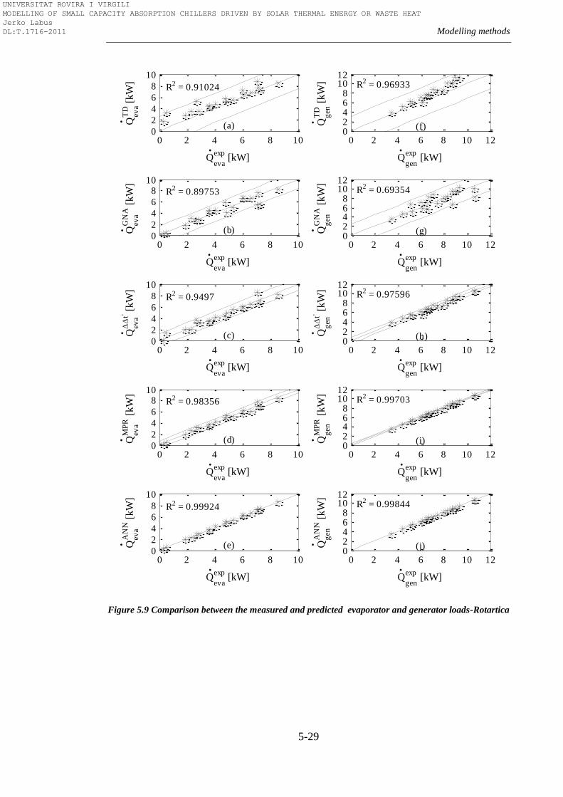
Modelling methods
5-29
Figure 5.9 Comparison between the measured and predicted evaporator and generator loads-Rotartica
0 2 4 6 8 100
2
4
6
8
10
R2 = 0.91024
(a)
Qeva
exp [kW]
Qev
a
TD
[k
W]
0 2 4 6 8 10 1202468
1012
R2 = 0.96933
(f)
Qgen
exp [kW]
Qg
en
TD
[k
W]
0 2 4 6 8 100
2
4
6
810
R2 = 0.89753
(b)
Qeva
exp [kW]
Qev
a
GN
A [
kW
]
0 2 4 6 8 10 1202468
1012
R2 = 0.69354
(g)
Qgen
exp [kW]
Qg
en
GN
A [
kW
]
0 2 4 6 8 100
2
4
6
8
10
R2 = 0.9497
(c)
Qeva
exp [kW]
Qev
a
t, [k
W]
0 2 4 6 8 10 1202468
1012
R2 = 0.97596
(h)
Qgen
exp [kW]
Qg
en
t, [k
W]
0 2 4 6 8 100
2
4
6
810
R2 = 0.98356
(d)
Qeva
exp [kW]
Qev
a
MP
R [
kW
]
0 2 4 6 8 10 1202468
1012
R2 = 0.99703
(i)
Qgen
exp [kW]
Qg
en
MP
R [
kW
]
0 2 4 6 8 100
2
4
6
8
10
R2 = 0.99924
(e)
Qeva
exp [kW]
Qev
a
AN
N [
kW
]
0 2 4 6 8 10 1202468
1012
R2 = 0.99844
(j)
Qgen
exp [kW]
Qg
en
AN
N [
kW
]
.
.
.
.
.
.
.
.
. .
.
.
.
.
.
.
.
.
.
.
UNIVERSITAT ROVIRA I VIRGILI MODELLING OF SMALL CAPACITY ABSORPTION CHILLERS DRIVEN BY SOLAR THERMAL ENERGY OR WASTE HEAT Jerko Labus DL:T.1716-2011
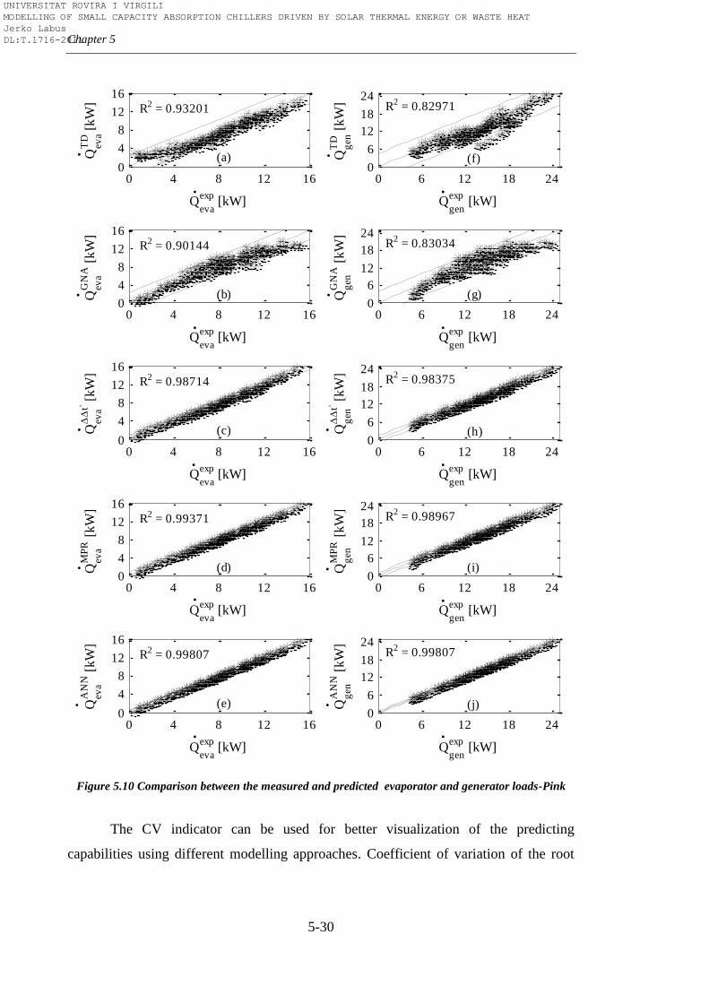
Chapter 5
5-30
Figure 5.10 Comparison between the measured and predicted evaporator and generator loads-Pink
The CV indicator can be used for better visualization of the predicting
capabilities using different modelling approaches. Coefficient of variation of the root
0 4 8 12 160
4
8
12
16
R2 = 0.93201
(a)
Qeva
exp [kW]
Qev
a
TD
[kW
]
0 6 12 18 240
6
12
18
24R2 = 0.82971
(f)
Qgen
exp [kW]
Qg
en
TD
[kW
]
0 4 8 12 160
4
8
12
16
R2 = 0.90144
(b)
Qeva
exp [kW]
Qev
a
GN
A [
kW
]
0 6 12 18 240
6
12
18
24R2 = 0.83034
(g)
Qgen
exp [kW]
Qg
en
GN
A [
kW
]
0 4 8 12 160
4
8
12
16
R2 = 0.98714
(c)
Qeva
exp [kW]
Qev
a
t, [kW
]
0 6 12 18 240
6
12
18
24R2 = 0.98375
(h)
Qgen
exp [kW]
Qg
en
t, [kW
]
0 4 8 12 160
4
8
12
16
R2 = 0.99371
(d)
Qeva
exp [kW]
Qev
a
MP
R [
kW
]
0 6 12 18 240
6
12
18
24R2 = 0.98967
(i)
Qgen
exp [kW]
Qg
en
MP
R [
kW
]
0 4 8 12 160
4
8
12
16
R2 = 0.99807
(e)
Qeva
exp [kW]
Qev
a
AN
N [
kW
]
0 6 12 18 240
6
12
18
24R2 = 0.99807
(j)
Qgen
exp [kW]
Qg
en
AN
N [
kW
]
.
.
.
.
.
.
.
.
.
.
.
.
.
.
.
.
.
.
.
.
UNIVERSITAT ROVIRA I VIRGILI MODELLING OF SMALL CAPACITY ABSORPTION CHILLERS DRIVEN BY SOLAR THERMAL ENERGY OR WASTE HEAT Jerko Labus DL:T.1716-2011
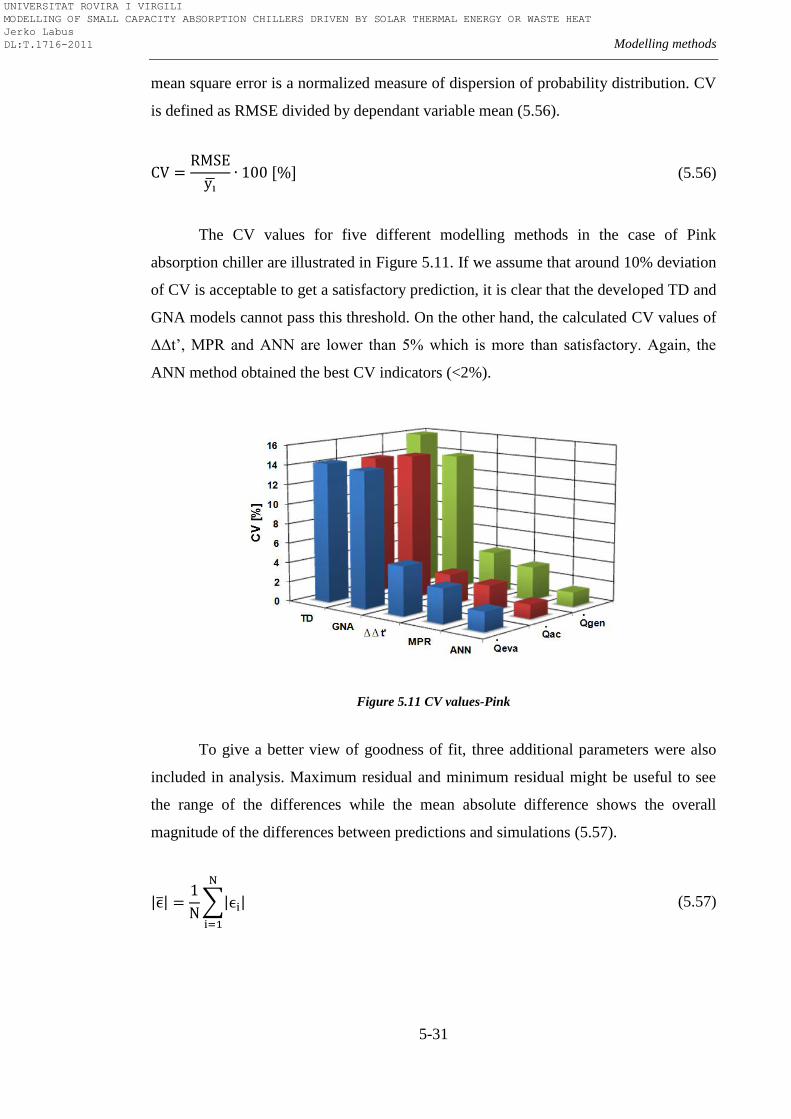
Modelling methods
5-31
mean square error is a normalized measure of dispersion of probability distribution. CV
is defined as RMSE divided by dependant variable mean (5.56).
(5.56)
The CV values for five different modelling methods in the case of Pink
absorption chiller are illustrated in Figure 5.11. If we assume that around 10% deviation
of CV is acceptable to get a satisfactory prediction, it is clear that the developed TD and
GNA models cannot pass this threshold. On the other hand, the calculated CV values of
ΔΔt’, MPR and ANN are lower than 5% which is more than satisfactory. Again, the
ANN method obtained the best CV indicators (<2%).
Figure 5.11 CV values-Pink
To give a better view of goodness of fit, three additional parameters were also
included in analysis. Maximum residual and minimum residual might be useful to see
the range of the differences while the mean absolute difference shows the overall
magnitude of the differences between predictions and simulations (5.57).
(5.57)
UNIVERSITAT ROVIRA I VIRGILI MODELLING OF SMALL CAPACITY ABSORPTION CHILLERS DRIVEN BY SOLAR THERMAL ENERGY OR WASTE HEAT Jerko Labus DL:T.1716-2011
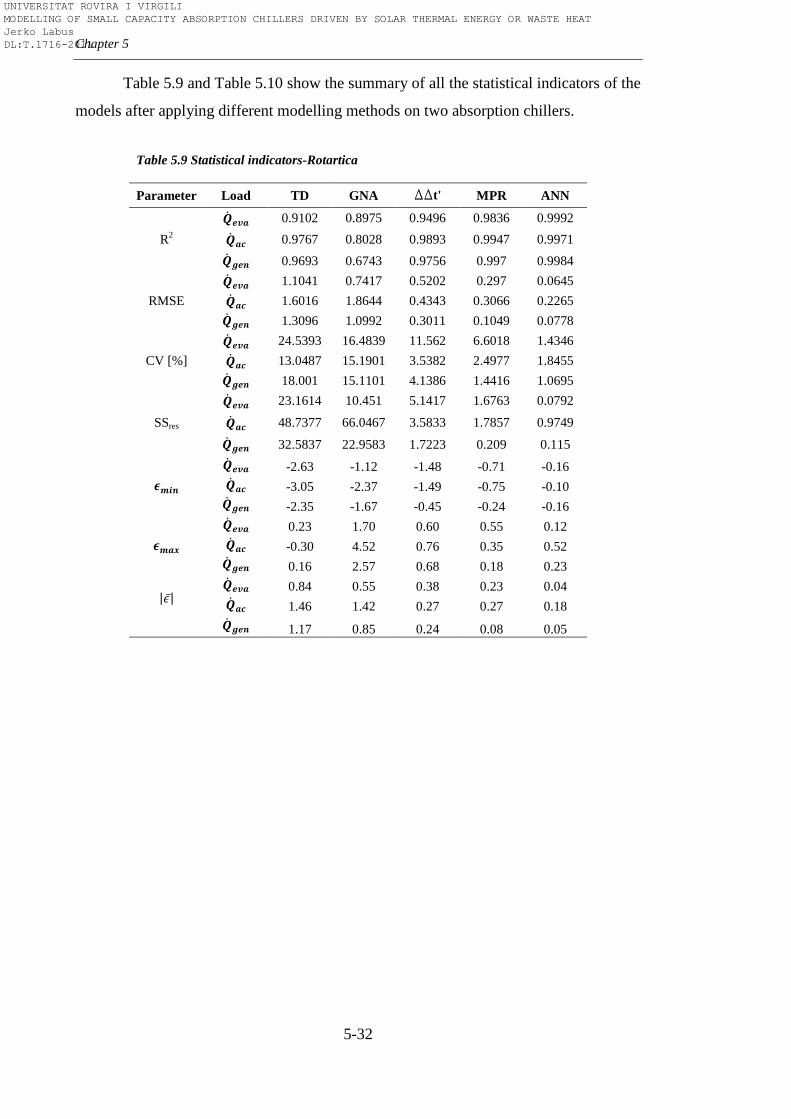
Chapter 5
5-32
Table 5.9 and Table 5.10 show the summary of all the statistical indicators of the
models after applying different modelling methods on two absorption chillers.
Table 5.9 Statistical indicators-Rotartica
Parameter Load TD GNA DDt' MPR ANN
R2
0.9102 0.8975 0.9496 0.9836 0.9992
0.9767 0.8028 0.9893 0.9947 0.9971
0.9693 0.6743 0.9756 0.997 0.9984
RMSE
1.1041 0.7417 0.5202 0.297 0.0645
1.6016 1.8644 0.4343 0.3066 0.2265
1.3096 1.0992 0.3011 0.1049 0.0778
CV [%]
24.5393 16.4839 11.562 6.6018 1.4346
13.0487 15.1901 3.5382 2.4977 1.8455
18.001 15.1101 4.1386 1.4416 1.0695
SSres
23.1614 10.451 5.1417 1.6763 0.0792
48.7377 66.0467 3.5833 1.7857 0.9749
32.5837 22.9583 1.7223 0.209 0.115
-2.63 -1.12 -1.48 -0.71 -0.16
-3.05 -2.37 -1.49 -0.75 -0.10
-2.35 -1.67 -0.45 -0.24 -0.16
0.23 1.70 0.60 0.55 0.12
-0.30 4.52 0.76 0.35 0.52
0.16 2.57 0.68 0.18 0.23
0.84 0.55 0.38 0.23 0.04
1.46 1.42 0.27 0.27 0.18
1.17 0.85 0.24 0.08 0.05
UNIVERSITAT ROVIRA I VIRGILI MODELLING OF SMALL CAPACITY ABSORPTION CHILLERS DRIVEN BY SOLAR THERMAL ENERGY OR WASTE HEAT Jerko Labus DL:T.1716-2011
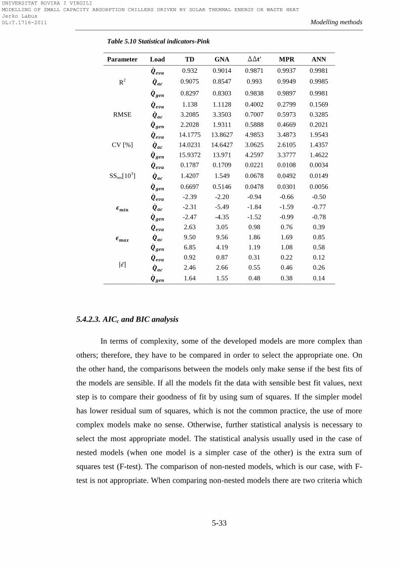
Modelling methods
5-33
Table 5.10 Statistical indicators-Pink
Parameter Load TD GNA DDt' MPR ANN
R2
0.932 0.9014 0.9871 0.9937 0.9981
0.9075 0.8547 0.993 0.9949 0.9985
0.8297 0.8303 0.9838 0.9897 0.9981
RMSE
1.138 1.1128 0.4002 0.2799 0.1569
3.2085 3.3503 0.7007 0.5973 0.3285
2.2028 1.9311 0.5888 0.4669 0.2021
CV [%]
14.1775 13.8627 4.9853 3.4873 1.9543
14.0231 14.6427 3.0625 2.6105 1.4357
15.9372 13.971 4.2597 3.3777 1.4622
SSres[103]
0.1787 0.1709 0.0221 0.0108 0.0034
1.4207 1.549 0.0678 0.0492 0.0149
0.6697 0.5146 0.0478 0.0301 0.0056
-2.39 -2.20 -0.94 -0.66 -0.50
-2.31 -5.49 -1.84 -1.59 -0.77
-2.47 -4.35 -1.52 -0.99 -0.78
2.63 3.05 0.98 0.76 0.39
9.50 9.56 1.86 1.69 0.85
6.85 4.19 1.19 1.08 0.58
0.92 0.87 0.31 0.22 0.12
2.46 2.66 0.55 0.46 0.26
1.64 1.55 0.48 0.38 0.14
5.4.2.3. AICc and BIC analysis
In terms of complexity, some of the developed models are more complex than
others; therefore, they have to be compared in order to select the appropriate one. On
the other hand, the comparisons between the models only make sense if the best fits of
the models are sensible. If all the models fit the data with sensible best fit values, next
step is to compare their goodness of fit by using sum of squares. If the simpler model
has lower residual sum of squares, which is not the common practice, the use of more
complex models make no sense. Otherwise, further statistical analysis is necessary to
select the most appropriate model. The statistical analysis usually used in the case of
nested models (when one model is a simpler case of the other) is the extra sum of
squares test (F-test). The comparison of non-nested models, which is our case, with F-
test is not appropriate. When comparing non-nested models there are two criteria which
UNIVERSITAT ROVIRA I VIRGILI MODELLING OF SMALL CAPACITY ABSORPTION CHILLERS DRIVEN BY SOLAR THERMAL ENERGY OR WASTE HEAT Jerko Labus DL:T.1716-2011
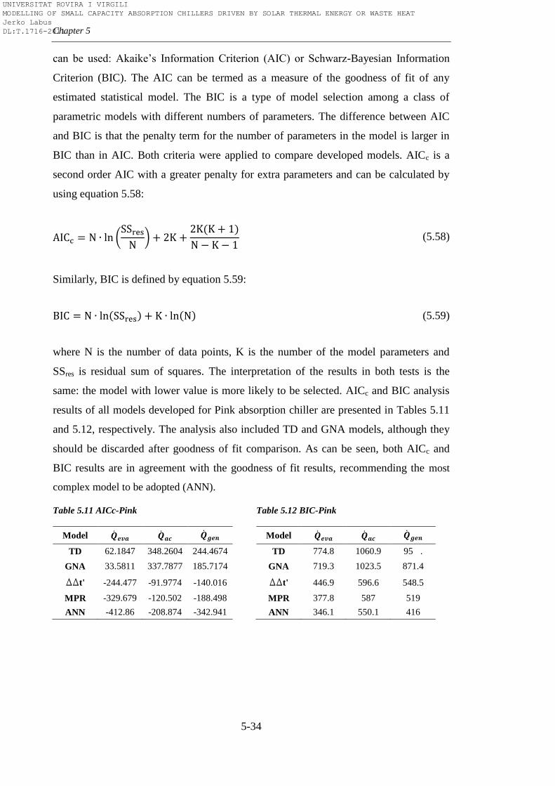
Chapter 5
5-34
can be used: Akaike’s Information Criterion (AIC) or Schwarz-Bayesian Information
Criterion (BIC). The AIC can be termed as a measure of the goodness of fit of any
estimated statistical model. The BIC is a type of model selection among a class of
parametric models with different numbers of parameters. The difference between AIC
and BIC is that the penalty term for the number of parameters in the model is larger in
BIC than in AIC. Both criteria were applied to compare developed models. AICc is a
second order AIC with a greater penalty for extra parameters and can be calculated by
using equation 5.58:
(5.58)
Similarly, BIC is defined by equation 5.59:
(5.59)
where N is the number of data points, K is the number of the model parameters and
SSres is residual sum of squares. The interpretation of the results in both tests is the
same: the model with lower value is more likely to be selected. AICc and BIC analysis
results of all models developed for Pink absorption chiller are presented in Tables 5.11
and 5.12, respectively. The analysis also included TD and GNA models, although they
should be discarded after goodness of fit comparison. As can be seen, both AICc and
BIC results are in agreement with the goodness of fit results, recommending the most
complex model to be adopted (ANN).
Table 5.11 AICc-Pink
Table 5.12 BIC-Pink
Model
TD 62.1847 348.2604 244.4674
GNA 33.5811 337.7877 185.7174
DDt' -244.477 -91.9774 -140.016
MPR -329.679 -120.502 -188.498
ANN -412.86 -208.874 -342.941
Model
TD 774.8 1060.9 95 .
GNA 719.3 1023.5 871.4
DDt' 446.9 596.6 548.5
MPR 377.8 587 519
ANN 346.1 550.1 416
UNIVERSITAT ROVIRA I VIRGILI MODELLING OF SMALL CAPACITY ABSORPTION CHILLERS DRIVEN BY SOLAR THERMAL ENERGY OR WASTE HEAT Jerko Labus DL:T.1716-2011
Modelling methods
5-35
5.5. Conclusions
In this Chapter a comprehensive comparison of different methods for steady
state modelling of small capacity absorption chillers was presented. Using both
mechanistic and empirical approaches, the models were developed based on
experimental data from our test bench and manufacturer catalogue. All the models, with
exception of TD which required some additional assumptions, were based only on the
measurements of external water circuits. Five different methods (TD, GNA, ΔΔt’, MPR,
ANN) were applied to model two commercial absorption chillers, one with small
dataset (Rotartica) and other with large dataset (Pink), in order to investigate the
influence of database size on the prediction of the models. The analysis showed that
models developed with small dataset are not reliable and statistically correct, since
small datasets are insufficient to form strong relationships within the models. On the
other hand, the models created with large dataset which completely covers the operating
range of the absorption chiller showed very high level of predicting capabilities. With
respect to that, it is very important to emphasize the significance of comprehensive and
accurate data sets in order to map properly the whole performance range. Reliable data
(reconciled measurements, accurate sensors, true steady-state data, etc.) reduce the
effect of random errors in data fitting. The results confirmed that TD method is more
suitable for design phase of absorption equipment and not for simulation packages due
to its complexity and numerous iterations which can cause problems in annual
simulations. The constant UA values are not an appropriate approach, because the
deviations increase significantly moving away from the nominal conditions. This is
clearly visible through the poor statistical indicators such as R2 and CV. Although the
GNA neither represents all the operating range with high accuracy, it is still used in
some simulation programs due to its simplicity. This is justified by a fact that on a
whole year hourly simulation, these deviations will most probably equal out to a great
extent. However, the results of statistical analysis indicate that more appropriate would
be to use another three methods in order to obtain better accuracy. Excellent statistical
indicators (R2 around 0.99, CV lower than 5% and narrow CL) clearly show that any of
the three different methods (ΔΔt’, MPR and ANN) is suitable for the performance
prediction of absorption systems, but also for other purposes: control and monitoring,
fault detection, and optimization.
UNIVERSITAT ROVIRA I VIRGILI MODELLING OF SMALL CAPACITY ABSORPTION CHILLERS DRIVEN BY SOLAR THERMAL ENERGY OR WASTE HEAT Jerko Labus DL:T.1716-2011

Chapter 5
5-36
Nevertheless, the best prediction was obtained with the ANN method with
R2>0.998 and CV<2%. The comparison of the models with AICc and BIC statistical
tests confirmed that ANN was the most suitable method to model Pink absorption
chiller.
UNIVERSITAT ROVIRA I VIRGILI MODELLING OF SMALL CAPACITY ABSORPTION CHILLERS DRIVEN BY SOLAR THERMAL ENERGY OR WASTE HEAT Jerko Labus DL:T.1716-2011
6-1
Chapter 6
Optimal control
“However beautiful the strategy, you should occasionally look at the results.”
Winston Churchill
6.1. Introduction
The control of HVAC systems has been a very active area of research and
development for many years. The progress of computer science and increasing
availability of control devices together with the growing concern on energy and cost
efficiency made that field of supervisory control become very attractive. Supervisory
control, also called optimal control, is the high level control which uses the optimization
techniques to find the most efficient settings for all the local controllers in terms of
minimizing the overall system energy input or operating cost. There are different
categories of supervisory control depending on used method. In this research, the
attention was paid to the model-based supervisory control. Two main components of
this control are the model and the optimization technique. The main function of the
model is to predict the system performance (or cost), as well as the system response to
the changes of control settings. On the other hand, the main function of the optimization
technique is to seek the optimal control settings in order to make the system more
efficient.
The main aim of Chapter 6 is to provide an insight of possible control strategies
for absorption chillers by using optimal control. For that purpose, two control strategies
were developed based on black-box models (ANN) using MatLab. Black-box models
are very suitable for supervisory control due to its simplicity and lower computational
costs when compared to physical models. However, they are only reliable for the
operating points within the range of covered data. The first developed strategy was
neural network inverse (ANNi) which allows selecting the parameters for the optimal
performance of the absorption chiller in order to achieve the required cooling capacity.
Second developed strategy couples ANN with Genetic Algorithms as optimization
UNIVERSITAT ROVIRA I VIRGILI MODELLING OF SMALL CAPACITY ABSORPTION CHILLERS DRIVEN BY SOLAR THERMAL ENERGY OR WASTE HEAT Jerko Labus DL:T.1716-2011
Chapter 6
6-2
technique to find the optimal operating conditions in order to optimize the performance
of the small system with absorption chiller. In addition, the existing achievements in the
field of control for absorption systems are provided to complete the image of these
systems.
6.2. Control strategies for absorption systems
The control of absorption chillers can be divided into two types: internal and
external. The internal control is usually determined by the manufacturer's design with
the main function to maintain the internal parameters (concentrations, flow rates,
pressures, temperatures) within the limits, which enable the smooth operation and
prevent the risks of damage. The absorption chiller is usually part of a larger system
where the changes in the external circuits affect the operation of the absorption chiller.
The external control of the absorption chiller deals with the parameters of the external
circuits in order to satisfy the cooling demand. This indicates a direct correlation
between these two types of control. The most relevant manipulable parameters to
control an absorption chiller externally are: hot medium inlet temperature and mass flow
rate, cooling medium inlet temperature and mass flow rate and chilling medium outlet
temperature and mass flow rate. The hot fluid inlet temperature depends on the control
of the heat supply system while the outlet temperature is a result of the momentary heat
flow in the generator. The cooling medium inlet temperature depends on the heat
dissipation component and its performance while the outlet temperature is a result of the
momentary heat flow in the absorber and condenser. The inlet temperature of the
chilling medium is the parameter which depends on chilling medium distribution system
and cannot be influenced. The outlet temperature of the chilling medium is the result of
the cooling demand and necessary temperature for the particular application. Usually,
this temperature is within certain limits to allow satisfactory operation of the chilling
distribution system.
The absorption systems explained in the patents of Mann [165] and Anderson
[166] had control which employed two separate temperature sensors, one to sense the
temperature of the fluid entering the system and another to sense the temperature of the
fluid medium after it has been chilled. The control was adapted to vary the refrigeration
UNIVERSITAT ROVIRA I VIRGILI MODELLING OF SMALL CAPACITY ABSORPTION CHILLERS DRIVEN BY SOLAR THERMAL ENERGY OR WASTE HEAT Jerko Labus DL:T.1716-2011
Optimal control
6-3
capacity of the system in response to varying load conditions and not in response to
changes in internal conditions in the refrigeration system itself. The disadvantage of this
control was that if there was any malfunction in the refrigeration system, the control
system would have resulted in maximum energy input to the refrigeration system, as an
attempt to compensate the malfunction. The fuzzy logic rules for a PID controller in a
control system for an absorption refrigerator were introduced by Ogawa et al. [167].
The controlled system was adapted to subject the outlet temperature of the chilling
medium to fuzzy logic control adjusting the amount of heat supplied to the generator.
Yeung et al. [168] described a simple control mechanism for chilled and cooling
medium (water) temperatures in a solar air-conditioning system in Hong Kong. The
control mechanism monitored the chilled water temperature and when it dropped below
the set point, the hot water supply to the chiller was cut off. The cooling water
temperature was controlled with a differential controller in on-off mode. The fan of the
wet cooling tower switched on when the cooling tower sump temperature exceeded
29.5°C and switched off at temperatures below. This control strategy resulted in a
fluctuating operation of the chiller with increased thermal losses due to a higher number
of start-up and shut-down procedures. Li and Sumathy [66] reported on the performance
of a solar powered absorption air conditioning system with a partitioned hot water
storage tank. They used an active control of the hot water feed-in position into the
storage tank, depending on available solar and tank temperatures. The goal of this setup
was an earlier chiller start-up in the morning due to a reduced storage tank volume. The
solar pump had no variable flow control and was operated only in differential on-off
mode. The cooling tower was a wet cooling tower with a differential on-off controller
for the fan. The storage tank was partitioned into two parts. This study showed that the
total solar cooling COP could be increased by approx. 15% compared to the traditional
whole-tank mode. Conventional absorption chiller control logic was embodied again in
the disclosure of Jenkins [169]. A control input for the absorption chiller was the heat
supply controlled by a capacity valve, which was in turn controlled by a PI controller.
The controller was controlled by a non-linear function. Optimal supervisory control
investigation of the equipment in a cooling plant with double effect absorption chiller
was carried out by Koeppel et al. [170] in order to minimize the total operating cost.
They developed a simplified strategy for cooling tower fan control for absorption
UNIVERSITAT ROVIRA I VIRGILI MODELLING OF SMALL CAPACITY ABSORPTION CHILLERS DRIVEN BY SOLAR THERMAL ENERGY OR WASTE HEAT Jerko Labus DL:T.1716-2011
Chapter 6
6-4
cooling plants that involves the determination of a linear relationship between a set
point for cooling tower supply water temperature and ambient wet-bulb temperature.
The optimization algorithm was formulated as a TRNSYS component model in which
the inputs were the control variables and the objective function. The application of this
simple strategy resulted in savings that were nearly identical to the optimization results.
Chow et al [171] developed a control strategy for the optimal use of fuel and electricity
for a direct-fired absorption chiller system. Multivariable model-based method of
supervisory control was applied by coupling ANNs with genetic algorithms (ANN
ability to learn complex nonlinear mapping together with the GA ability to search the
global optimum). The results from this study showed that considerable amount of
energy can be saved since such supervisory controller allows an overall consideration of
the interactions among the systems and their controlled variables. The possibility of
supervisory and optimal control strategies of HVAC systems were explained
comprehensively by Wang and Ma [172].
According to Henning [13], there are two main control modes to control
absorption cooling systems depending on application purpose. The first mode is a heat-
guided mode characterized by a direct transformation of the available supply heat into
cold. There is neither active control of the chilled fluid temperature nor cooling
capacity; as long as there is sufficient heat to drive the absorption chiller, the cold is
produced. There are two possible variations of this mode, with or without heat storage
tank. Without a heat storage tank, only a thermal inertia of the chiller and building
causes temporal delays since there is a direct link between heat supply (i.e. solar
collectors) and cold supply to the building. The cold can be produced fast but without
limitation of its quantity. This can lead to very low inlet temperature of chilled water,
which can cause freezing of the evaporator, and to frequent transient load operations,
which leads to the conclusion that this mode is not suitable for air-conditioning
purposes with a steady demand of cold. The second mode is cold-guided mode, where
the chilling medium temperature is set to fulfil the cooling demand. This mode requires
a constant amount of heat supplied to the generator. The constant heat supply can be
obtained in various ways with respect to the cooling system design and to the absorption
chiller type. The chilled water temperature can be controlled by adjusting either hot or
cooling water inlet temperature of the absorption chiller.
UNIVERSITAT ROVIRA I VIRGILI MODELLING OF SMALL CAPACITY ABSORPTION CHILLERS DRIVEN BY SOLAR THERMAL ENERGY OR WASTE HEAT Jerko Labus DL:T.1716-2011
Optimal control
6-5
The control of large-scale absorption chillers is normally provided through the
hot medium circuit. Usually, when designing a control strategy of an absorption chiller
in air-conditioning applications the primary objective is to control the capacity by
maintaining the temperature of the chilling fluid leaving the evaporator. The internal
control system compares the temperature of the leaving fluid to the set point and adjusts
the amount of solution supplied to the generator by adjusting heat input to the generator.
The combination of solution temperature and concentration determines the temperature
at which the refrigerant vaporizes in the evaporator. Varying the temperature at which
the refrigerant boils in the evaporator changes the capacity of the absorption chiller.
Thus, in order to control the capacity of the chiller to meet the ever-changing system
loads, either the solution temperature or the solution concentration must be varied. A
common method to vary the temperature of the solution is to vary the amount of
absorbent solution delivered to generator. The most common ways are to use throttling
valve or a bypass valve. More expensive way is to use adjustable frequency drive to
vary speed of the generator pump motor, thus reducing the flow of the solution to the
generator. In order to vary the solution concentration, absorption chillers vary the heat
input to the generator. Nowadays, almost all large-scale absorption chillers are equipped
with a microprocessor-based control panel that monitors and controls all operations of
the machine [173-175]. The common way to control large capacity absorption chillers is
through the modulating energy valve. In response of outlet chilled water temperature,
the valve close, which reduces the heat input to the generator. There are two variation of
this control, depending on manufacturer’s design. The first variation can be seen, for
instance, at YORK steam and hot water chillers which are equipped with control valves
capable of modulating steam or hot-water flow continuously from 10-100%. The second
variation is when hot water control valve adjusts the hot water inlet temperature in order
to maintain chilled water temperature [175]. Using the energy valve as sole method of
control would cause the slow response of the chiller to a capacity change. By varying
the solution flow rate, especially with the use of adjustable frequency drives, recent
chiller designs are now able to react much faster to ever-changing load and cooling
water conditions. Similarly, in direct-fired absorption chillers the amount of heat input
to the generator is varied by modulating the capacity of the burner. Between 30 and 100
UNIVERSITAT ROVIRA I VIRGILI MODELLING OF SMALL CAPACITY ABSORPTION CHILLERS DRIVEN BY SOLAR THERMAL ENERGY OR WASTE HEAT Jerko Labus DL:T.1716-2011
Chapter 6
6-6
percent of cooling capacity the burner firing rate is adjusted to meet the cooling load.
Below 30 percent the burner is cycled [176].
The temperature of the cooling water (cooling tower circuit) also has a
significant impact on the operation of absorption chillers. In order to provide stable
control of the cooling water temperature, a cooling tower bypass is typically
recommended. In some new chillers and control designs, variable speed drives are used
to vary the flow of the solution, allowing the chiller to maintain tight control in
situations where the cooling water temperature may be highly variable. However,
modulating control kit increases the installation cost of the chiller and that is the main
reason why large number of installed chillers operate only with simple ON-OFF control
strategy. A study of Perez de Vinaspre et al. [177] gives an example of ON-OFF control
strategy for direct-fired double effect absorption chiller (Yazaki). The signal from the
thermostat starts the burner and the chiller operates until it reaches the target impulsion
temperature of 7ºC. After reaching that point, the operation stops and starts again when
the return temperature of the primary circuit is above the target temperature (10ºC) due
to an increase of the building thermal load. However, due to the low demand for air-
conditioning of the building with respect to the chilling capacity of the absorption
chiller, the on/off cycles were frequent and short. The average chilling capacity was
63% of nominal value and 59% of scheduled time the chiller was on standby. These
facts point out the significance of absorption chiller sizing in ON-OFF control strategy.
In contrast to large-scale absorption chillers, which have been present at the
market for a long time, the interest for small-scale absorption chillers has been found
recently. With only a few commercial units and with small number of expert groups
working in this research field, the control issues are still in the phase of development.
The usual control for small capacity absorption chillers is ON-OFF operation [178,
179]. The main problem for this type of the control is thermal inertia. When the chiller
is turned off it cools down and if the following ON period is delayed by the thermal
inertia the negative effect is visible in large reduction of COP. Two other possible
control strategies were considered by the same author. The first strategy used the hot
water inlet temperature to modulate the capacity of the chiller. This allowed the
modulation of more than 50% of the chilling capacity. The second control strategy was
UNIVERSITAT ROVIRA I VIRGILI MODELLING OF SMALL CAPACITY ABSORPTION CHILLERS DRIVEN BY SOLAR THERMAL ENERGY OR WASTE HEAT Jerko Labus DL:T.1716-2011
Optimal control
6-7
to actuate on hot water flow rate. A lower rate of the generator raised the temperature
difference between the inlet and outlet of the generator with an overall lower mean
temperature. The effect on the whole was less pronounced than in the first strategy, but
it had the advantage of fully using the available temperature level without an inefficient
mixing to produce lower temperatures. Finally, Lazzarin considered the option to use
both strategies. However, the results showed that the penalisation was unavoidable
whenever the machine is modulated to meet directly the cooling demand.
The catalogues of the commercial units [180-182] show that most of small
capacity absorption chillers are controlled either by simple ON-OFF cycling or by
modulating valve in the hot water circuit. It is also possible to modulate flow rates of
hot and cooling medium circuits but this option is limited for some chillers [181] due to
very narrow range of the flow rates permitted by manufacturer design. If the flow rates
limits are exceeded, the internal control normally turns off the chiller to prevent any
damage. Once when absorption chiller is started, it will operate automatically and
remain in operation as long as there is a cooling demand. The hot water circuit pump or
bypass valve is cycled ON and OFF to control the flow or temperature of the heat
medium through the generator in response to the chilled water temperature. When the
chilled water temperature reaches the required level, the solution dilutes and the pump
in the chilled water circuit stops. The temperature than starts to rise and when it reaches
the differential temperature parameter added to the set point the chiller turns on again.
The set points of manipulable heat medium temperatures are adjustable only in ranges
prescribed by manufacturer.
The facts exposed above indicate that small capacity chillers are in general
installed to work at full load operation in order to have higher efficiency. On the other
hand, this reveals the fact that the simple control of the absorption chiller is not enough.
The design of whole system together with control strategy of all the system components
is crucial in order to obtain efficiency comparable to the conventional systems. The
design and control strategy in a cooling system with various components (cold and hot
storage tanks, solar circuit, back up heater, cooling tower or air condenser and terminal
units) should be conducted carefully in order to be cost-effective and efficient. The
control of a cooling system can be done in various ways, depending on application and
UNIVERSITAT ROVIRA I VIRGILI MODELLING OF SMALL CAPACITY ABSORPTION CHILLERS DRIVEN BY SOLAR THERMAL ENERGY OR WASTE HEAT Jerko Labus DL:T.1716-2011
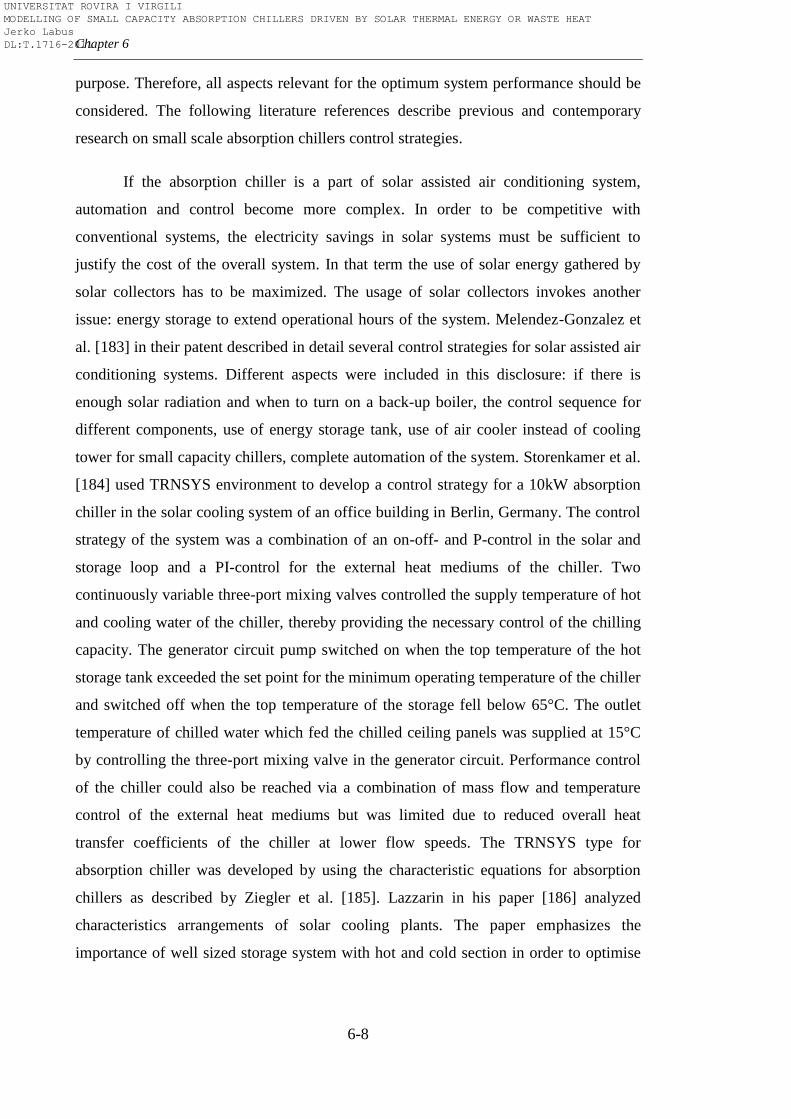
Chapter 6
6-8
purpose. Therefore, all aspects relevant for the optimum system performance should be
considered. The following literature references describe previous and contemporary
research on small scale absorption chillers control strategies.
If the absorption chiller is a part of solar assisted air conditioning system,
automation and control become more complex. In order to be competitive with
conventional systems, the electricity savings in solar systems must be sufficient to
justify the cost of the overall system. In that term the use of solar energy gathered by
solar collectors has to be maximized. The usage of solar collectors invokes another
issue: energy storage to extend operational hours of the system. Melendez-Gonzalez et
al. [183] in their patent described in detail several control strategies for solar assisted air
conditioning systems. Different aspects were included in this disclosure: if there is
enough solar radiation and when to turn on a back-up boiler, the control sequence for
different components, use of energy storage tank, use of air cooler instead of cooling
tower for small capacity chillers, complete automation of the system. Storenkamer et al.
[184] used TRNSYS environment to develop a control strategy for a 10kW absorption
chiller in the solar cooling system of an office building in Berlin, Germany. The control
strategy of the system was a combination of an on-off- and P-control in the solar and
storage loop and a PI-control for the external heat mediums of the chiller. Two
continuously variable three-port mixing valves controlled the supply temperature of hot
and cooling water of the chiller, thereby providing the necessary control of the chilling
capacity. The generator circuit pump switched on when the top temperature of the hot
storage tank exceeded the set point for the minimum operating temperature of the chiller
and switched off when the top temperature of the storage fell below 65°C. The outlet
temperature of chilled water which fed the chilled ceiling panels was supplied at 15°C
by controlling the three-port mixing valve in the generator circuit. Performance control
of the chiller could also be reached via a combination of mass flow and temperature
control of the external heat mediums but was limited due to reduced overall heat
transfer coefficients of the chiller at lower flow speeds. The TRNSYS type for
absorption chiller was developed by using the characteristic equations for absorption
chillers as described by Ziegler et al. [185]. Lazzarin in his paper [186] analyzed
characteristics arrangements of solar cooling plants. The paper emphasizes the
importance of well sized storage system with hot and cold section in order to optimise
UNIVERSITAT ROVIRA I VIRGILI MODELLING OF SMALL CAPACITY ABSORPTION CHILLERS DRIVEN BY SOLAR THERMAL ENERGY OR WASTE HEAT Jerko Labus DL:T.1716-2011
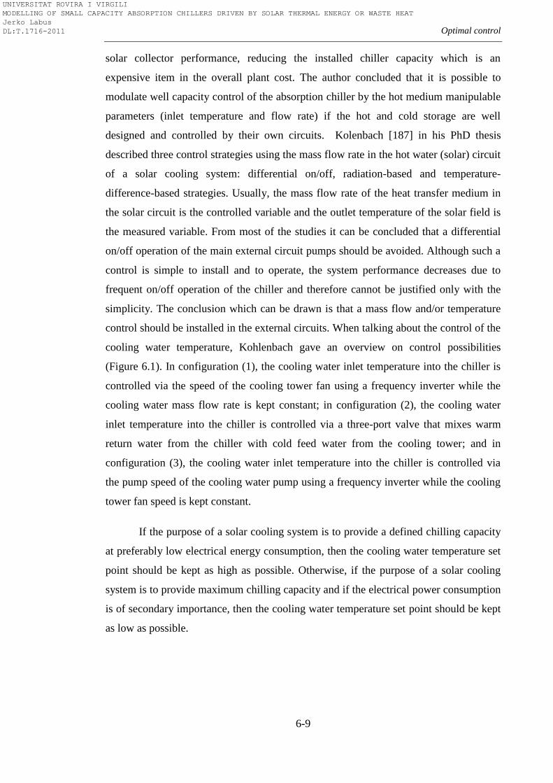
Optimal control
6-9
solar collector performance, reducing the installed chiller capacity which is an
expensive item in the overall plant cost. The author concluded that it is possible to
modulate well capacity control of the absorption chiller by the hot medium manipulable
parameters (inlet temperature and flow rate) if the hot and cold storage are well
designed and controlled by their own circuits. Kolenbach [187] in his PhD thesis
described three control strategies using the mass flow rate in the hot water (solar) circuit
of a solar cooling system: differential on/off, radiation-based and temperature-
difference-based strategies. Usually, the mass flow rate of the heat transfer medium in
the solar circuit is the controlled variable and the outlet temperature of the solar field is
the measured variable. From most of the studies it can be concluded that a differential
on/off operation of the main external circuit pumps should be avoided. Although such a
control is simple to install and to operate, the system performance decreases due to
frequent on/off operation of the chiller and therefore cannot be justified only with the
simplicity. The conclusion which can be drawn is that a mass flow and/or temperature
control should be installed in the external circuits. When talking about the control of the
cooling water temperature, Kohlenbach gave an overview on control possibilities
(Figure 6.1). In configuration (1), the cooling water inlet temperature into the chiller is
controlled via the speed of the cooling tower fan using a frequency inverter while the
cooling water mass flow rate is kept constant; in configuration (2), the cooling water
inlet temperature into the chiller is controlled via a three-port valve that mixes warm
return water from the chiller with cold feed water from the cooling tower; and in
configuration (3), the cooling water inlet temperature into the chiller is controlled via
the pump speed of the cooling water pump using a frequency inverter while the cooling
tower fan speed is kept constant.
If the purpose of a solar cooling system is to provide a defined chilling capacity
at preferably low electrical energy consumption, then the cooling water temperature set
point should be kept as high as possible. Otherwise, if the purpose of a solar cooling
system is to provide maximum chilling capacity and if the electrical power consumption
is of secondary importance, then the cooling water temperature set point should be kept
as low as possible.
UNIVERSITAT ROVIRA I VIRGILI MODELLING OF SMALL CAPACITY ABSORPTION CHILLERS DRIVEN BY SOLAR THERMAL ENERGY OR WASTE HEAT Jerko Labus DL:T.1716-2011
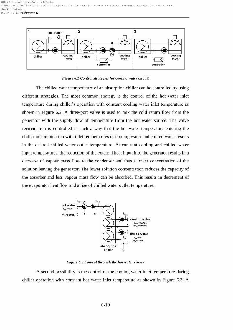
Chapter 6
6-10
Figure 6.1 Control strategies for cooling water circuit
The chilled water temperature of an absorption chiller can be controlled by using
different strategies. The most common strategy is the control of the hot water inlet
temperature during chiller’s operation with constant cooling water inlet temperature as
shown in Figure 6.2. A three-port valve is used to mix the cold return flow from the
generator with the supply flow of temperature from the hot water source. The valve
recirculation is controlled in such a way that the hot water temperature entering the
chiller in combination with inlet temperatures of cooling water and chilled water results
in the desired chilled water outlet temperature. At constant cooling and chilled water
input temperatures, the reduction of the external heat input into the generator results in a
decrease of vapour mass flow to the condenser and thus a lower concentration of the
solution leaving the generator. The lower solution concentration reduces the capacity of
the absorber and less vapour mass flow can be absorbed. This results in decrement of
the evaporator heat flow and a rise of chilled water outlet temperature.
Figure 6.2 Control through the hot water circuit
A second possibility is the control of the cooling water inlet temperature during
chiller operation with constant hot water inlet temperature as shown in Figure 6.3. A
UNIVERSITAT ROVIRA I VIRGILI MODELLING OF SMALL CAPACITY ABSORPTION CHILLERS DRIVEN BY SOLAR THERMAL ENERGY OR WASTE HEAT Jerko Labus DL:T.1716-2011
Optimal control
6-11
three-port valve is used to mix the warm return flow from the condenser with the cold
supply flow of temperature from the cooling water source. The valve recirculation is
controlled in such way that the cooling water temperature entering the chiller in
combination with inlet temperatures of hot water and chilled water results in the desired
chilled water outlet temperature. For constant hot and chilled water inlet temperatures as
well as mass flows, an increase in cooling water temperature decreases the absorber
capacity; therefore less water vapour can be evaporated in the evaporator. The heat flow
decreases and the chilled water outlet temperature increases.
Figure 6.3 Control through the cooling water circuit
A combination of both hot and cooling water based strategies can also be used.
If the hot water inlet temperature is not sufficient for a given chilling load, the cooling
water temperature can be lowered in order to reach the desired chilled water
temperature. The optimum combination of hot and cooling water control depends on the
user-specified conditions.
Clauß et al. [188] presented the strategy based on the characteristic equation
model which determines the required cooling water temperature. If the hot water
temperature is not high enough for a given chilling load, cooling water temperature is
lowered and vice versa, when the driving temperature is high cooling water temperature
is increased. In the parametric study of Kuhn et al. [189] TRNSYS simulations were
carried out in order to compare control strategies for the absorption chiller.
Conventional control by hot water adjustment was compared with a new control method
by cooling water adjustment. In conventional control, the system controls chilling
capacity within the set point plus the deadband by sensing the outlet chilled water and
UNIVERSITAT ROVIRA I VIRGILI MODELLING OF SMALL CAPACITY ABSORPTION CHILLERS DRIVEN BY SOLAR THERMAL ENERGY OR WASTE HEAT Jerko Labus DL:T.1716-2011
Chapter 6
6-12
regulating the hot water control valve via a mechanically linked actuator motor. Cooling
water adjustment was done by using the characteristic equation model to find a
governing temperature of inlet cooling water for PID controller. The results showed that
the new strategy provides stable chilled water outlet temperature and also decreases
parasitic electricity consumption of auxiliary equipment with respect to the
conventional strategy. Characteristic equation was used again by Albers et al. [190] as a
tool for improving part load behaviour of 35kW commercial absorption chiller. The
information which is coded in the characteristic temperature function allows replacing a
change in driving temperature against the change in cooling water temperature. This
gives rise to the possibility to optimize the electricity consumption of the cooling tower
fans and pumps against the temperature of the driving heat which will in turn influence
the collector efficiency. This control strategy requires the combined control of generator
and cooling water circuit, which is not common practice. Pietrushka et al. [191]
analysed seven cases with different control options for a 15kW H2O-LiBr absorption
chiller system. The results of a simulation showed that a fan speed control of the
cooling tower ventilator as well as a ΔT-control of the cold distribution system are
essential to obtain a high electrical COP of the system. The best overall efficiency was
obtained when the generator temperature was allowed to vary between 70°C and
90(95)°C at the lowest possible set point for the absorber inlet temperature. Zetzsche et
al. [192] in their study involved ice storage in a solar plant with 10kW absorption
chiller. On the building side, the control parameter was the inlet water temperature into
the rooms followed by sensor for relative humidity. When the dew point was reached,
the sensor provided a signal to the controller and the flow through the chilled ceiling of
this particular room stopped. On the solar plant side, absorption chiller was directly fed
from solar collectors without any control. Consequently, the chiller started to operate
when the minimum required hot water inlet temperature was available. The evaporation
in the generator started when a certain temperature level was reached. If the required
temperature level was not available, the outlet temperature of the generator was almost
equal to the inlet temperature. A stored program control unit controlled the chiller. This
control unit switched all pumps and the dry cooling tower on and off while the internal
valves were regulated in such a way that COP was always at maximum.
UNIVERSITAT ROVIRA I VIRGILI MODELLING OF SMALL CAPACITY ABSORPTION CHILLERS DRIVEN BY SOLAR THERMAL ENERGY OR WASTE HEAT Jerko Labus DL:T.1716-2011
Optimal control
6-13
The examples exposed above show that absorption chillers can be controlled in
various ways. The main problem which impedes direct control of the absorption chillers
is thermal inertia, the capability of the absorption cycle to store the energy. This is more
expressed in the case of large capacity absorption chillers due to their size and large
heat exchangers. The control in this case is through hot medium circuit by modulating
the capacity of the burner or by modulating valve with respect to chilled water outlet
temperature. The control prevents chiller to shut down and to avoid delay which would
cause new start of the same. Otherwise, chiller would be working with simple ON-OFF
cycling control which would decrease the overall performance as seen in the case study
of Perez de Vinaspre et al. [177]. On the other hand, in the case of small capacity
absorption chillers, small size and the possibility of using compact heat exchangers
significantly reduce the solution charge and consequently the effect of thermal inertia.
The response of these chillers to changes of external circuits inlet conditions is much
faster in comparison with large capacity chillers. Some studies and experience in work
with small capacity absorption chillers can confirm that their response can be very fast
(especially units up to 15kW capacities). The control of these chillers can also be
performed in several ways as seen above, but the results of various studies, as well as
best practice, recommend four possible strategies. The first is conventional method by
adjusting the hot water inlet temperature in order to control the outlet chilled water
temperature. The second method is to control the inlet cooling water temperature to
maintain the chilled water set temperature at required part load operation when hot
water temperature is constant. The adjustment can be done by using the frequency
inverter or three port valve, depending on heat dissipation component (cooling tower,
dry cooler). The third and maybe the optimum method is a combination of both hot and
cooling water based strategies. However, user-defined conditions determine the
optimum combination of hot and cooling water control. The control of the absorption
chillers by adjusting flow rates is not recommendable whereas the modulation of the
cooling capacity is too small due to narrow ranges which come with manufacturer’s
design. The realization of any of the three control strategies requires a controller for
maintaining the set temperature. In a practical application, the correct parameters of
such a controller have to be identified for stable system operation. This requires a
proper model of the chiller which will be implemented in the controller through the
UNIVERSITAT ROVIRA I VIRGILI MODELLING OF SMALL CAPACITY ABSORPTION CHILLERS DRIVEN BY SOLAR THERMAL ENERGY OR WASTE HEAT Jerko Labus DL:T.1716-2011

Chapter 6
6-14
transfer function. A whole system design and sizing is another important parameter
beside the absorption chiller control strategy, in order to be high efficient and therefore
cost competitive. Nevertheless, special care has to be given to the electrical
consumption of the parasitic equipment (pumps and fans). Sometimes, when cooling
demand is very low and absorption chiller works at lower part loads, electrical
consumption of these devices may decrease electrical COP significantly. In that case
ON-OFF control is the correct choice in order to increase the overall efficiency.
6.3. Artificial Neural Network Inverse (ANNi)
The main idea of ANNi methodology is to use the neural network model by
coupling it with the optimization algorithm to find the optimal input values for the
required output. Therefore, ANNi can be considered as model-based method of
supervisory control, in which the values of the manipulable parameters are obtained by
solving an on-line optimization problem to obtain the required output [193, 194]. The
term inverse indicates that the direction of the ANN/optimization algorithm
combination is opposite: from required output to the optimized parameters. Since the
model was developed with constant flow rates and the chilled water output temperature
almost always has a fixed value in air-conditioning (fan-coils, chilled ceilings), the
controlling parameters should be the other two external temperatures (the generator inlet
temperature and the absorber/condenser inlet temperature) because they have the
greatest influence on the chiller performance. Chilling capacity was chosen as the
required output. As will be shown in continuation, the very low percentage of error and
short computing time make this methodology suitable for the on-line control of
absorption cooling systems.
6.3.1. ANN model
The ANN model of Pink absorption chiller developed in Chapter 5 for as
function of three input parameters ( ,
, ) was used to demonstrate the
feasibility of ANNi to be used as control strategy. was defined by equation 6.1:
UNIVERSITAT ROVIRA I VIRGILI MODELLING OF SMALL CAPACITY ABSORPTION CHILLERS DRIVEN BY SOLAR THERMAL ENERGY OR WASTE HEAT Jerko Labus DL:T.1716-2011
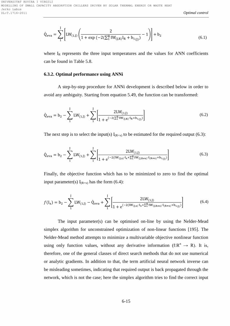
Optimal control
6-15
(
(6.1)
where IR represents the three input temperatures and the values for ANN coefficients
can be found in Table 5.8.
6.3.2. Optimal performance using ANNi
A step-by-step procedure for ANNi development is described below in order to
avoid any ambiguity. Starting from equation 5.49, the function can be transformed:
(6.2)
The next step is to select the input(s) I(R=x) to be estimated for the required output (6.3):
(6.3)
Finally, the objective function which has to be minimized to zero to find the optimal
input parameter(s) I(R=x) has the form (6.4):
(6.4)
The input parameter(s) can be optimised on-line by using the Nelder-Mead
simplex algorithm for unconstrained optimization of non-linear functions [195]. The
Nelder-Mead method attempts to minimize a multivariable objective nonlinear function
using only function values, without any derivative information (f:Rn
→ R). It is,
therefore, one of the general classes of direct search methods that do not use numerical
or analytic gradients. In addition to that, the term artificial neural network inverse can
be misleading sometimes, indicating that required output is back propagated through the
network, which is not the case; here the simplex algorithm tries to find the correct input
UNIVERSITAT ROVIRA I VIRGILI MODELLING OF SMALL CAPACITY ABSORPTION CHILLERS DRIVEN BY SOLAR THERMAL ENERGY OR WASTE HEAT Jerko Labus DL:T.1716-2011
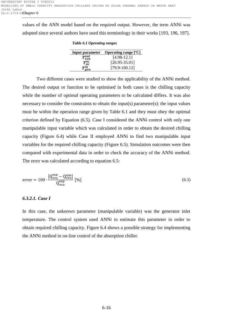
Chapter 6
6-16
values of the ANN model based on the required output. However, the term ANNi was
adopted since several authors have used this terminology in their works [193, 196, 197].
Table 6.1 Operating ranges
Input parameter Operating range [ºC]
[4.98-12.1]
[26.95-35.01]
[79.9-100.12]
Two different cases were studied to show the applicability of the ANNi method.
The desired output or function to be optimised in both cases is the chilling capacity
while the number of optimal operating parameters to be calculated differs. It was also
necessary to consider the constraints to obtain the input(s) parameter(s): the input values
must be within the operation range given by Table 6.1 and they must obey the optimal
criterion defined by Equation (6.5). Case I considered the ANNi control with only one
manipulable input variable which was calculated in order to obtain the desired chilling
capacity (Figure 6.4) while Case II employed ANNi to find two manipulable input
variables for the required chilling capacity (Figure 6.5). Simulation outcomes were then
compared with experimental data in order to check the accuracy of the ANNi method.
The error was calculated according to equation 6.5:
(6.5)
6.3.2.1. Case I
In this case, the unknown parameter (manipulable variable) was the generator inlet
temperature. The control system used ANNi to estimate this parameter in order to
obtain required chilling capacity. Figure 6.4 shows a possible strategy for implementing
the ANNi method in on-line control of the absorption chiller.
UNIVERSITAT ROVIRA I VIRGILI MODELLING OF SMALL CAPACITY ABSORPTION CHILLERS DRIVEN BY SOLAR THERMAL ENERGY OR WASTE HEAT Jerko Labus DL:T.1716-2011
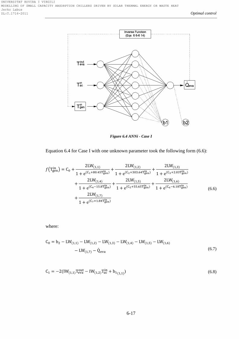
Optimal control
6-17
Figure 6.4 ANNi - Case I
Equation 6.4 for Case I with one unknown parameter took the following form (6.6):
(6.6)
where:
(6.7)
) (6.8)
UNIVERSITAT ROVIRA I VIRGILI MODELLING OF SMALL CAPACITY ABSORPTION CHILLERS DRIVEN BY SOLAR THERMAL ENERGY OR WASTE HEAT Jerko Labus DL:T.1716-2011
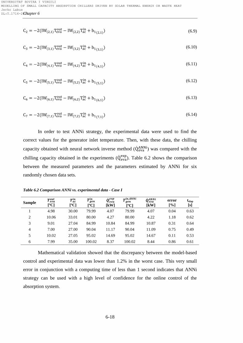
Chapter 6
6-18
(6.9)
(6.10)
(6.11)
(6.12)
(6.13)
(6.14)
In order to test ANNi strategy, the experimental data were used to find the
correct values for the generator inlet temperature. Then, with these data, the chilling
capacity obtained with neural network inverse method ( ) was compared with the
chilling capacity obtained in the experiments (
). Table 6.2 shows the comparison
between the measured parameters and the parameters estimated by ANNi for six
randomly chosen data sets.
Table 6.2 Comparison ANNi vs. experimental data - Case I
Sample
[ºC]
[ºC]
[ºC]
[kW]
[ºC]
[kW]
error
[%]
telap
[s]
1 4.98 30.00 79.99 4.07 79.99 4.07 0.04 0.63
2 10.06 33.01 80.00 4.27 80.00 4.22 1.18 0.62
3 9.01 27.04 84.99 10.84 84.99 10.87 0.31 0.64
4 7.00 27.00 90.04 11.17 90.04 11.09 0.75 0.49
5 10.02 27.05 95.02 14.69 95.02 14.67 0.11 0.53
6 7.99 35.00 100.02 8.37 100.02 8.44 0.86 0.61
Mathematical validation showed that the discrepancy between the model-based
control and experimental data was lower than 1.2% in the worst case. This very small
error in conjunction with a computing time of less than 1 second indicates that ANNi
strategy can be used with a high level of confidence for the online control of the
absorption system.
UNIVERSITAT ROVIRA I VIRGILI MODELLING OF SMALL CAPACITY ABSORPTION CHILLERS DRIVEN BY SOLAR THERMAL ENERGY OR WASTE HEAT Jerko Labus DL:T.1716-2011
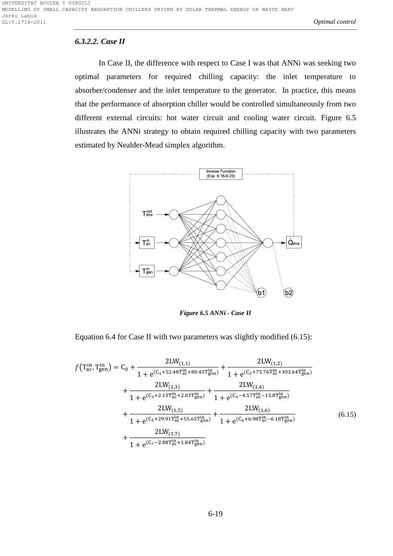
Optimal control
6-19
6.3.2.2. Case II
In Case II, the difference with respect to Case I was that ANNi was seeking two
optimal parameters for required chilling capacity: the inlet temperature to
absorber/condenser and the inlet temperature to the generator. In practice, this means
that the performance of absorption chiller would be controlled simultaneously from two
different external circuits: hot water circuit and cooling water circuit. Figure 6.5
illustrates the ANNi strategy to obtain required chilling capacity with two parameters
estimated by Nealder-Mead simplex algorithm.
Figure 6.5 ANNi - Case II
Equation 6.4 for Case II with two parameters was slightly modified (6.15):
(6.15)
UNIVERSITAT ROVIRA I VIRGILI MODELLING OF SMALL CAPACITY ABSORPTION CHILLERS DRIVEN BY SOLAR THERMAL ENERGY OR WASTE HEAT Jerko Labus DL:T.1716-2011
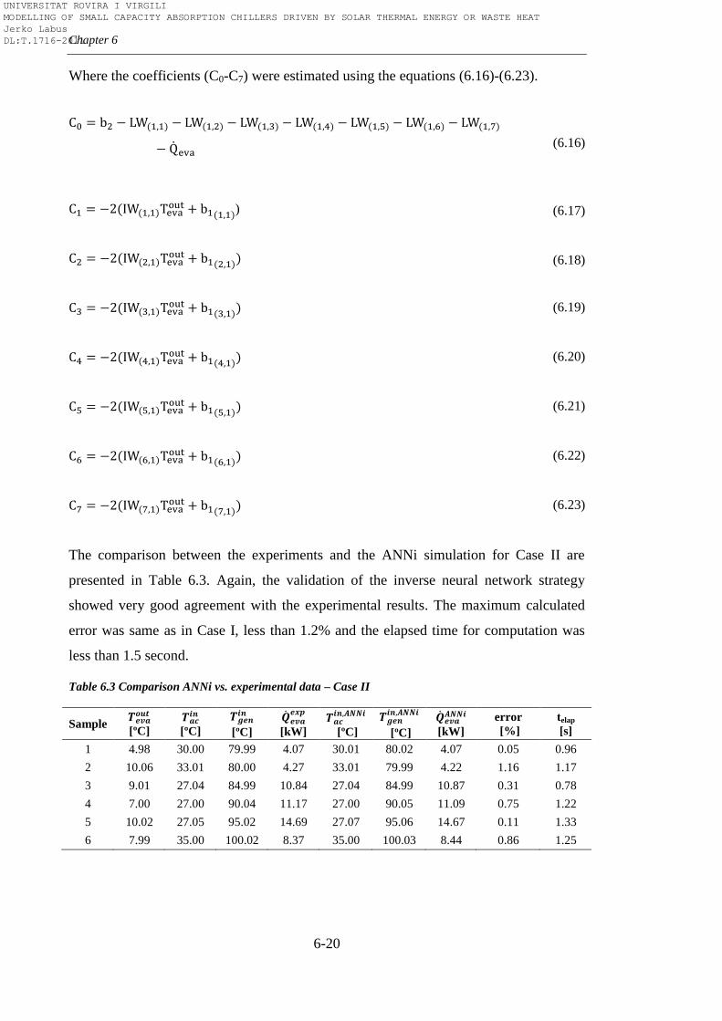
Chapter 6
6-20
Where the coefficients (C0-C7) were estimated using the equations (6.16)-(6.23).
(6.16)
) (6.17)
(6.18)
(6.19)
(6.20)
(6.21)
(6.22)
(6.23)
The comparison between the experiments and the ANNi simulation for Case II are
presented in Table 6.3. Again, the validation of the inverse neural network strategy
showed very good agreement with the experimental results. The maximum calculated
error was same as in Case I, less than 1.2% and the elapsed time for computation was
less than 1.5 second.
Table 6.3 Comparison ANNi vs. experimental data – Case II
Sample
[ºC]
[ºC]
[ºC]
[kW]
[ºC]
[ºC]
[kW]
error
[%]
telap
[s]
1 4.98 30.00 79.99 4.07 30.01 80.02 4.07 0.05 0.96
2 10.06 33.01 80.00 4.27 33.01 79.99 4.22 1.16 1.17
3 9.01 27.04 84.99 10.84 27.04 84.99 10.87 0.31 0.78
4 7.00 27.00 90.04 11.17 27.00 90.05 11.09 0.75 1.22
5 10.02 27.05 95.02 14.69 27.07 95.06 14.67 0.11 1.33
6 7.99 35.00 100.02 8.37 35.00 100.03 8.44 0.86 1.25
UNIVERSITAT ROVIRA I VIRGILI MODELLING OF SMALL CAPACITY ABSORPTION CHILLERS DRIVEN BY SOLAR THERMAL ENERGY OR WASTE HEAT Jerko Labus DL:T.1716-2011
Optimal control
6-21
As can be seen from both cases studied, ANNi seems to be very suitable for
implementation in online control of absorption systems. Very close agreement with
experimental data and short computation time confirmed that. Also, it is obvious that
performance of ANNi is in direct correlation with ANN model of absorption chiller.
The more accurate the ANN model is, the better will be the ANNi performance.
Therefore, for precise control it is of great importance that ANN model has high
statistical indicators. It is also possible to include other input parameters in ANNi
control strategy, for instance, external flow rates. In that case, the use of variable speed
pumps would be necessary. More information about this can be found in the paper of
Labus et al. [198]. With respect to Case II, it is important to mention that sometimes is
difficult to control , especially when absorption chiller is connected to a cooling
tower, since it directly depends on ambient temperature and humidity. This problem can
be solved by adding more constraints using IF THAN logic (taking care to avoid any
confusion within the controller). However, the use of additional constraints depends on
requirements of each particular application.
6.4. Genetic Algorithm (GA) coupled with ANN
The genetic algorithm is a method for solving both constrained and
unconstrained optimization problems which was inspired by the process of natural
evolution. The GA is based on the principles of the evolution via natural selection,
employing a population of individuals that undergo selection in the presence of genetic
operators such as mutation and crossover. The algorithm mimics the process of the
evolution of populations by selecting only fit individuals for reproduction. Therefore,
this algorithm belongs to the class of optimum search methods which combine the
elements of direct and stochastic search methods. The working principle of GA method
is the following: the algorithm continuously modifies a population of individuals and at
each step selects individuals randomly from the current population to be parents and
uses them to produce offspring for the next generation. Each individual represents a
possible solution to a given problem. During the reproduction process, the individuals in
the current generation are evaluated by a value of fitness function, which is a measure
how close is the individual to the problem solution. Over successive generations, the
population of individuals evolves toward an optimal solution. The three most important
UNIVERSITAT ROVIRA I VIRGILI MODELLING OF SMALL CAPACITY ABSORPTION CHILLERS DRIVEN BY SOLAR THERMAL ENERGY OR WASTE HEAT Jerko Labus DL:T.1716-2011
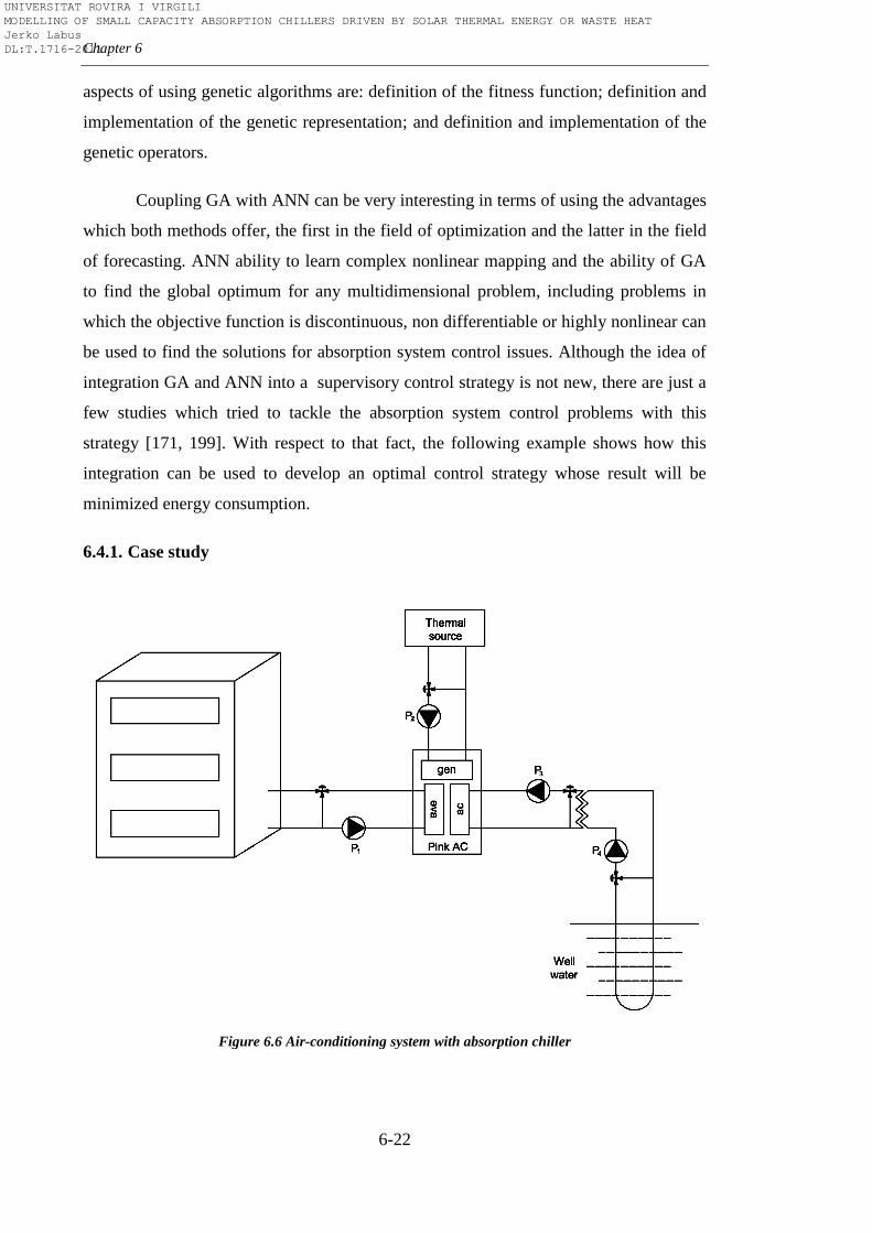
Chapter 6
6-22
aspects of using genetic algorithms are: definition of the fitness function; definition and
implementation of the genetic representation; and definition and implementation of the
genetic operators.
Coupling GA with ANN can be very interesting in terms of using the advantages
which both methods offer, the first in the field of optimization and the latter in the field
of forecasting. ANN ability to learn complex nonlinear mapping and the ability of GA
to find the global optimum for any multidimensional problem, including problems in
which the objective function is discontinuous, non differentiable or highly nonlinear can
be used to find the solutions for absorption system control issues. Although the idea of
integration GA and ANN into a supervisory control strategy is not new, there are just a
few studies which tried to tackle the absorption system control problems with this
strategy [171, 199]. With respect to that fact, the following example shows how this
integration can be used to develop an optimal control strategy whose result will be
minimized energy consumption.
6.4.1. Case study
Figure 6.6 Air-conditioning system with absorption chiller
UNIVERSITAT ROVIRA I VIRGILI MODELLING OF SMALL CAPACITY ABSORPTION CHILLERS DRIVEN BY SOLAR THERMAL ENERGY OR WASTE HEAT Jerko Labus DL:T.1716-2011
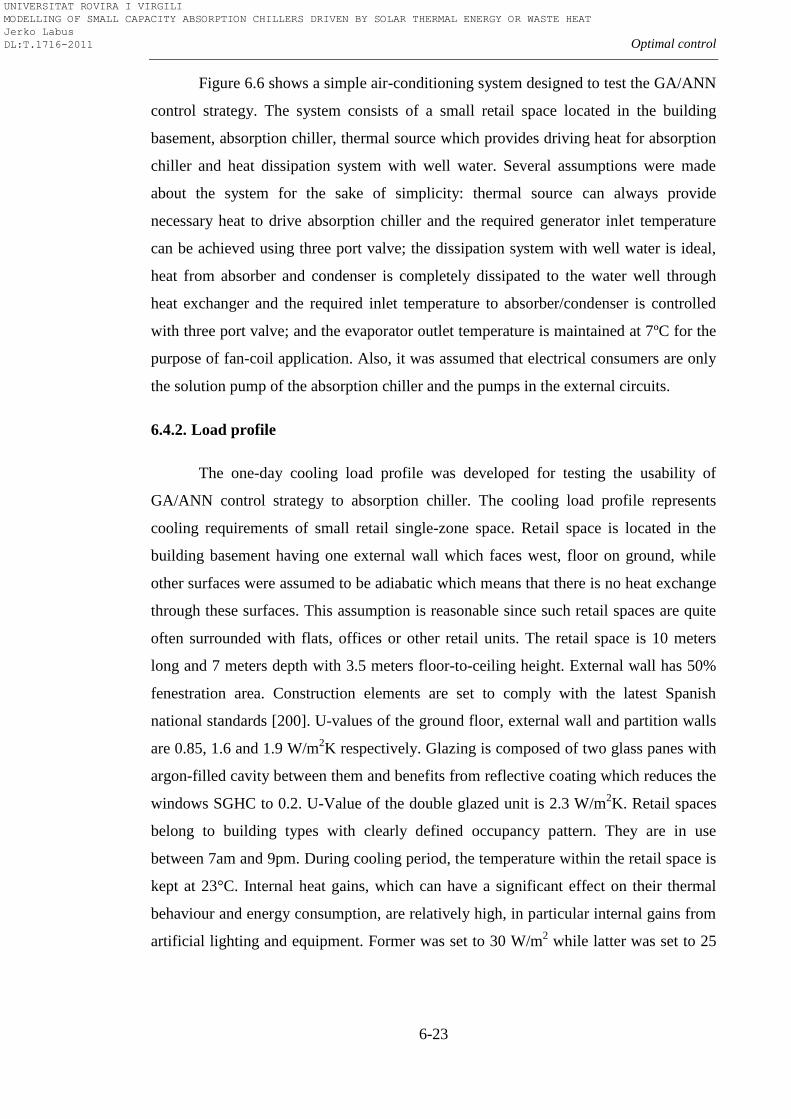
Optimal control
6-23
Figure 6.6 shows a simple air-conditioning system designed to test the GA/ANN
control strategy. The system consists of a small retail space located in the building
basement, absorption chiller, thermal source which provides driving heat for absorption
chiller and heat dissipation system with well water. Several assumptions were made
about the system for the sake of simplicity: thermal source can always provide
necessary heat to drive absorption chiller and the required generator inlet temperature
can be achieved using three port valve; the dissipation system with well water is ideal,
heat from absorber and condenser is completely dissipated to the water well through
heat exchanger and the required inlet temperature to absorber/condenser is controlled
with three port valve; and the evaporator outlet temperature is maintained at 7ºC for the
purpose of fan-coil application. Also, it was assumed that electrical consumers are only
the solution pump of the absorption chiller and the pumps in the external circuits.
6.4.2. Load profile
The one-day cooling load profile was developed for testing the usability of
GA/ANN control strategy to absorption chiller. The cooling load profile represents
cooling requirements of small retail single-zone space. Retail space is located in the
building basement having one external wall which faces west, floor on ground, while
other surfaces were assumed to be adiabatic which means that there is no heat exchange
through these surfaces. This assumption is reasonable since such retail spaces are quite
often surrounded with flats, offices or other retail units. The retail space is 10 meters
long and 7 meters depth with 3.5 meters floor-to-ceiling height. External wall has 50%
fenestration area. Construction elements are set to comply with the latest Spanish
national standards [200]. U-values of the ground floor, external wall and partition walls
are 0.85, 1.6 and 1.9 W/m2K respectively. Glazing is composed of two glass panes with
argon-filled cavity between them and benefits from reflective coating which reduces the
windows SGHC to 0.2. U-Value of the double glazed unit is 2.3 W/m2K. Retail spaces
belong to building types with clearly defined occupancy pattern. They are in use
between 7am and 9pm. During cooling period, the temperature within the retail space is
kept at 23°C. Internal heat gains, which can have a significant effect on their thermal
behaviour and energy consumption, are relatively high, in particular internal gains from
artificial lighting and equipment. Former was set to 30 W/m2 while latter was set to 25
UNIVERSITAT ROVIRA I VIRGILI MODELLING OF SMALL CAPACITY ABSORPTION CHILLERS DRIVEN BY SOLAR THERMAL ENERGY OR WASTE HEAT Jerko Labus DL:T.1716-2011
Chapter 6
6-24
W/m2. The occupant density was set to 8 m
2/person with a total heat gain of 125
W/person. In addition to internal gains, fresh air requirements were also defined. A
minimum of 10 l/s per person was supplied in order to satisfy fresh air requirements.
Fan-coil system was selected to maintain desired indoor conditions. The principle of
operation is fairly simplified. Fan coil is composed of fan and cooling coil. Fresh air is
supplied directly through fan-coil unit where it is mixed with re-circulated air before
passing the cooling coil. Indoor temperature is controlled by local thermostat which
varies water flow rate through cooling coil to respond to the zone demand. Chilled
water is supplied from the absorption chiller at constant temperature of 7°C. In the case
when there is no need for cooling, fan-coil fan is switched off.
In order to test the GA/ANN, the EnergyPlus simulation was run only for the
summer design day by using Barcelona Airport weather file. The hourly profile is
shown in Figure 6.7.
Figure 6.7 Daily profile for July 15
6.4.3. Optimal control settings
The general scheme of the linking of the optimization algorithm with ANN
model is given in Figure 6.8. The optimization process starts with identification of the
input variables and their constraints. Next step is to initialize the GA population of the
input variables for use in optimum search. The prediction of the system outputs based
0
2
4
6
8
10
12
14
Bu
ild
ing
dem
an
d [
kW
]
Time [h]
UNIVERSITAT ROVIRA I VIRGILI MODELLING OF SMALL CAPACITY ABSORPTION CHILLERS DRIVEN BY SOLAR THERMAL ENERGY OR WASTE HEAT Jerko Labus DL:T.1716-2011
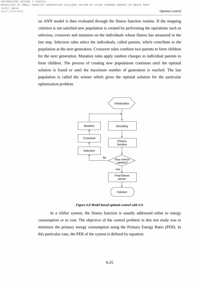
Optimal control
6-25
on ANN model is then evaluated through the fitness function routine. If the stopping
criterion is not satisfied new population is created by performing the operations such as
selection, crossover and mutation on the individuals whose fitness has measured in the
last step. Selection rules select the individuals, called parents, which contribute to the
population at the next generation. Crossover rules combine two parents to form children
for the next generation. Mutation rules apply random changes to individual parents to
form children. The process of creating new populations continues until the optimal
solution is found or until the maximum number of generation is reached. The last
population is called the winner which gives the optimal solution for the particular
optimization problem.
In a chiller system, the fitness function is usually addressed either to energy
consumption or to cost. The objective of the control problem in this test study was to
minimize the primary energy consumption using the Primary Energy Ratio (PER). In
this particular case, the PER of the system is defined by equation:
Figure 6.8 Model based optimal control with GA
Initialization
Decoding
Fitness
function
Stop criterion
satisfied?
Mutation
Crossover
Selection
Final fitness
winner
Solution
Yes
No
UNIVERSITAT ROVIRA I VIRGILI MODELLING OF SMALL CAPACITY ABSORPTION CHILLERS DRIVEN BY SOLAR THERMAL ENERGY OR WASTE HEAT Jerko Labus DL:T.1716-2011
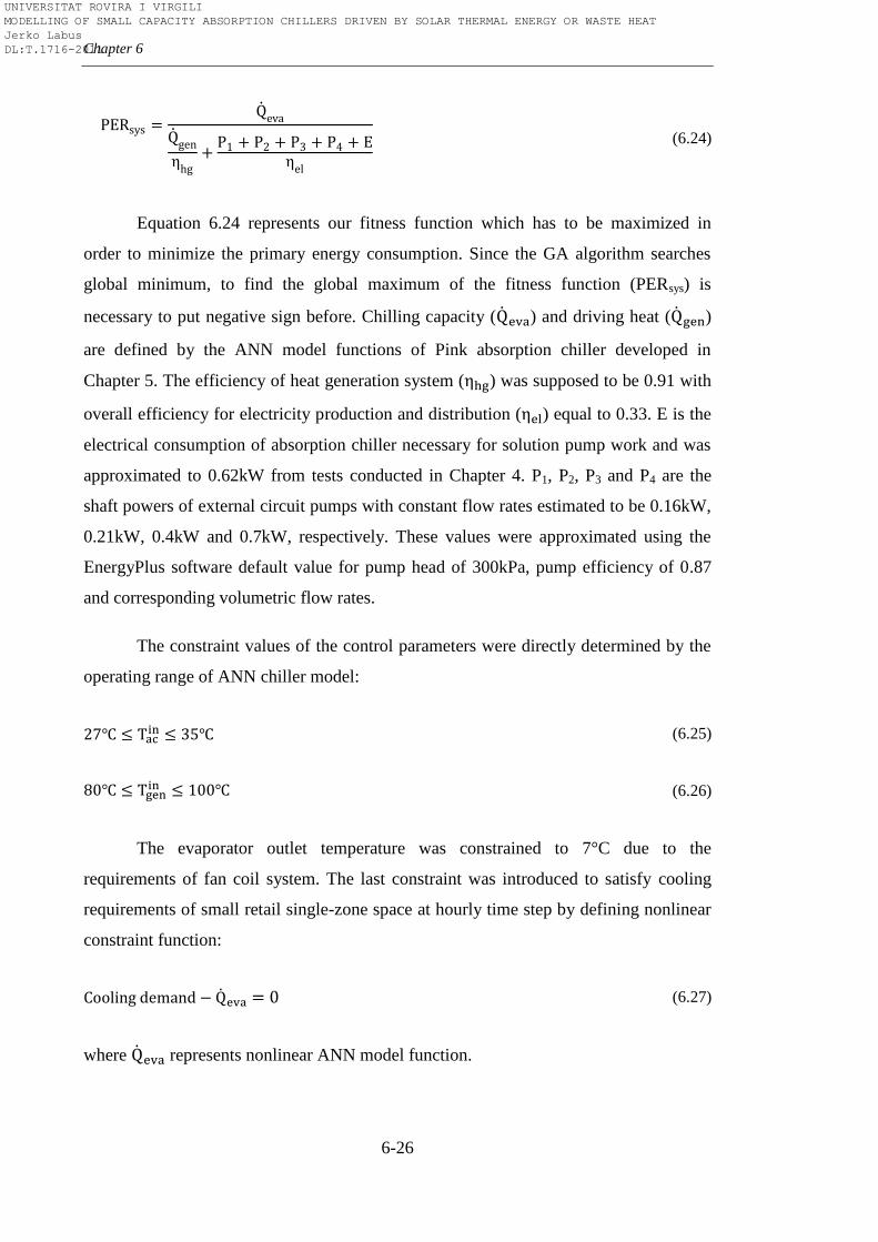
Chapter 6
6-26
(6.24)
Equation 6.24 represents our fitness function which has to be maximized in
order to minimize the primary energy consumption. Since the GA algorithm searches
global minimum, to find the global maximum of the fitness function (PERsys) is
necessary to put negative sign before. Chilling capacity ( ) and driving heat ( )
are defined by the ANN model functions of Pink absorption chiller developed in
Chapter 5. The efficiency of heat generation system ( ) was supposed to be 0.91 with
overall efficiency for electricity production and distribution ( ) equal to 0.33. E is the
electrical consumption of absorption chiller necessary for solution pump work and was
approximated to 0.62kW from tests conducted in Chapter 4. P1, P2, P3 and P4 are the
shaft powers of external circuit pumps with constant flow rates estimated to be 0.16kW,
0.21kW, 0.4kW and 0.7kW, respectively. These values were approximated using the
EnergyPlus software default value for pump head of 300kPa, pump efficiency of 0.87
and corresponding volumetric flow rates.
The constraint values of the control parameters were directly determined by the
operating range of ANN chiller model:
(6.25)
(6.26)
The evaporator outlet temperature was constrained to 7°C due to the
requirements of fan coil system. The last constraint was introduced to satisfy cooling
requirements of small retail single-zone space at hourly time step by defining nonlinear
constraint function:
(6.27)
where represents nonlinear ANN model function.
UNIVERSITAT ROVIRA I VIRGILI MODELLING OF SMALL CAPACITY ABSORPTION CHILLERS DRIVEN BY SOLAR THERMAL ENERGY OR WASTE HEAT Jerko Labus DL:T.1716-2011
Optimal control
6-27
The genetic algorithm parameters used during the set up in MatLab GA Toolbox
were the following:
Population size (=60). This value is a trade off between the efficiency of
the searching process and computing time, since lower population can
terminate the search at false optima while the larger population will
increase the execution time.
Ranking scaling function was selected to convert raw fitness scores
returned by the fitness function to values in a range that is suitable for the
selection function.
Roulette-Wheel method was selected as selection operator to choose
parents for the next generation based on their scaled values from the
fitness scaling function.
Crossover fraction (=0.8). This parameter specifies the fraction of the
crossover products in next generation. The number of individuals that are
guaranteed to survive to the next generation was set to 2.
Adaptive feasible randomly generates directions that are adaptive with
respect to the last successful or unsuccessful generation. A step length is
chosen along each direction so that linear constraints and bounds are
satisfied.
The selected mutation function was Adaptive feasible function. Mutation
function makes small random changes of the individuals in the population
and provides genetic diversity. Adaptive feasible function randomly
generates directions that are adaptive with respect to the last successful or
unsuccessful generation at the same time satisfying the constraints.
Migration direction of individuals between subpopulations was forward,
with migration fraction of 0.2 applied every 20 generations.
6.4.4. Results
Table 6.4 lists the results at each time step after performing GA on observed
system. The optimal solutions for the required cooling demand at each time step were
found in less than 20 generations. The execution time was approximately 3-4min on
4GHz PC. The obtained control temperatures are all within the constraint limits. It may
UNIVERSITAT ROVIRA I VIRGILI MODELLING OF SMALL CAPACITY ABSORPTION CHILLERS DRIVEN BY SOLAR THERMAL ENERGY OR WASTE HEAT Jerko Labus DL:T.1716-2011
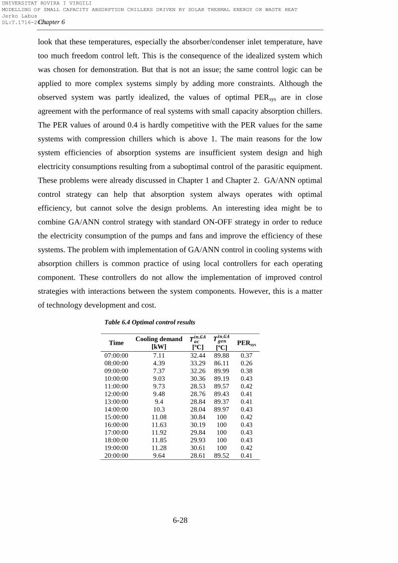
Chapter 6
6-28
look that these temperatures, especially the absorber/condenser inlet temperature, have
too much freedom control left. This is the consequence of the idealized system which
was chosen for demonstration. But that is not an issue; the same control logic can be
applied to more complex systems simply by adding more constraints. Although the
observed system was partly idealized, the values of optimal PERsys are in close
agreement with the performance of real systems with small capacity absorption chillers.
The PER values of around 0.4 is hardly competitive with the PER values for the same
systems with compression chillers which is above 1. The main reasons for the low
system efficiencies of absorption systems are insufficient system design and high
electricity consumptions resulting from a suboptimal control of the parasitic equipment.
These problems were already discussed in Chapter 1 and Chapter 2. GA/ANN optimal
control strategy can help that absorption system always operates with optimal
efficiency, but cannot solve the design problems. An interesting idea might be to
combine GA/ANN control strategy with standard ON-OFF strategy in order to reduce
the electricity consumption of the pumps and fans and improve the efficiency of these
systems. The problem with implementation of GA/ANN control in cooling systems with
absorption chillers is common practice of using local controllers for each operating
component. These controllers do not allow the implementation of improved control
strategies with interactions between the system components. However, this is a matter
of technology development and cost.
Table 6.4 Optimal control results
Time Cooling demand
[kW]
[ºC]
[ºC] PERsys
07:00:00 7.11 32.44 89.88 0.37
08:00:00 4.39 33.29 86.11 0.26
09:00:00 7.37 32.26 89.99 0.38
10:00:00 9.03 30.36 89.19 0.43
11:00:00 9.73 28.53 89.57 0.42
12:00:00 9.48 28.76 89.43 0.41
13:00:00 9.4 28.84 89.37 0.41
14:00:00 10.3 28.04 89.97 0.43
15:00:00 11.08 30.84 100 0.42
16:00:00 11.63 30.19 100 0.43
17:00:00 11.92 29.84 100 0.43
18:00:00 11.85 29.93 100 0.43
19:00:00 11.28 30.61 100 0.42
20:00:00 9.64 28.61 89.52 0.41
UNIVERSITAT ROVIRA I VIRGILI MODELLING OF SMALL CAPACITY ABSORPTION CHILLERS DRIVEN BY SOLAR THERMAL ENERGY OR WASTE HEAT Jerko Labus DL:T.1716-2011
Optimal control
6-29
6.5. Conclusions
In this Chapter, two different optimal control strategies for small capacity
absorption chillers were presented: ANNi and GA coupled with ANN. The both
strategies used the ANN model developed with experimental data of Pink absorption
machine. Consequently, the performance of both strategies is directly dependent of the
ANN model accuracy.
In ANNi, the Nealder-Mead simplex method of optimization was applied to find
optimal input parameter(s) for the required chilling capacity. In two cases analysed,
ANNi was used to estimate one and two unknown input parameters. The manipulable
variables considered to obtain the desired output were the inlet temperatures to the
absorber/condenser and to the generator. The results showed that the required output
can be achieved with a small error (less than 1.2%). Also, the computing time taken by
this methodology was less than 1.5 seconds which is much less than the time needed to
achieve steady operating conditions.
GA/ANN control strategy was demonstrated through a case study where the
Pink absorption chiller was implemented in a small system particularly designed for this
purpose. GA optimization method was applied to find two control input parameters of
the system for which the system will satisfy the cooling demand operating with optimal
efficiency at the same time. The computation time of the strategy was around 4min. The
optimal PER of around 0.4 reflects the reality of the performance of small capacity
absorption systems and emphasize again the importance of the system design.
All these facts make the proposed methodologies attractive for implementing in
the online control system of absorption chillers.
UNIVERSITAT ROVIRA I VIRGILI MODELLING OF SMALL CAPACITY ABSORPTION CHILLERS DRIVEN BY SOLAR THERMAL ENERGY OR WASTE HEAT Jerko Labus DL:T.1716-2011

UNIVERSITAT ROVIRA I VIRGILI MODELLING OF SMALL CAPACITY ABSORPTION CHILLERS DRIVEN BY SOLAR THERMAL ENERGY OR WASTE HEAT Jerko Labus DL:T.1716-2011
7-1
Chapter 7
Conclusions and Future Work
“As for the future, your task is not to foresee it, but to enable it.”
Antoine de Saint-Exupery
7.1. Summary and conclusions
The work carried out in this thesis has met the originally proposed aim, which
was the development of the comprehensive methodology of testing, modelling and
control strategy development for small capacity absorption machines. The developed
methodology covers all the important steps in experimental work with small capacity
absorption machines which are the base for simple, yet accurate models of these
machines. These models, based only on external circuits’ parameters, can be developed
by using several approaches. The developed methodology also described how to choose
the most appropriate model and how that model can further be implemented in software
packages or used for control purposes.
In order to provide better understanding of absorption technologies,
comprehensive literature review was presented in Chapter 2. This review provided
important information about absorption machines, from operating principles to their
usability and applications. Special attention was given to small capacity absorption
machines, in accordance with the main aim of this thesis. The latest achievements in the
field of small capacity absorption machines were presented as well as the review of
actual trends and most promising applications for their use, such as solar cooling and
CCHP. The achievements from the last two decades showed a considerable progress;
however, there are a lot of barriers which must be overcome in order to make them
competitive with vapour compression units. The obstacles such as high first cost, lack of
serial production, lower performance, inadequate control and usually poor system
design are main reasons which prevent the full use of absorption machines potential,
especially in the field of primary energy savings and environmental benefits.
Regulations and incentives are some of the measures which are necessary for further
UNIVERSITAT ROVIRA I VIRGILI MODELLING OF SMALL CAPACITY ABSORPTION CHILLERS DRIVEN BY SOLAR THERMAL ENERGY OR WASTE HEAT Jerko Labus DL:T.1716-2011
Chapter 7
7-2
development. However, regulations and incentives are only a part of the solution. The
second part of the solution, in order to accelerate the progress and to fill the gap with
respect to the conventional systems, is development of appropriate standards, test
procedures and best practices guides together with intensified work on simulations,
optimization and control strategies improvement.
A state of the art test bench was presented in Chapter 3 as very important tool
which facilitates the testing of small capacity absorption machines and helps to evaluate
their performance and benefits. In detail description of the test bench was given together
with the complete explanation of the different configurations which permit the tests
under different modes of operation, depending on machine or application purposes. The
multifunctional test bench, built in accordance with existing standards, was a very
important element of the developed methodology in order to obtain accurate and reliable
data which were further used for modelling and other purposes.
However, the multifunctional test bench itself was not sufficient. To obtain
accurate and reliable data, it was necessary to develop a comprehensive procedure
which would cover all the important aspects of the experimental work. The procedure
which allows obtaining the steady state performance data of any small capacity
absorption machine was developed by using and combining the existing knowledge and
experience in the fields of absorption and compression machines. The comprehensive
tests were performed on two different small capacity absorption machines, Rotarica and
Pink, in order to achieve this goal. Off-line steady state detector for absorption chillers
was developed based on analogy with steady state detector for vapour compression
chillers by using the moving window average. Additional steady state filter was
developed to remove all the residual transient samples, if they appear. Two additional
checks were added to the steady state detection procedure to confirm steady state
operating conditions.
The final result was the test procedure which contains several important steps:
test planning, data modelling, how to develop detector for steady-state conditions, the
uncertainty estimation and the analysis of the results. Very extensive measurements
performed on two absorption machines served to validate the functionality of two
operating modes in the novel test bench: chiller and heat pump modes. Around 50
UNIVERSITAT ROVIRA I VIRGILI MODELLING OF SMALL CAPACITY ABSORPTION CHILLERS DRIVEN BY SOLAR THERMAL ENERGY OR WASTE HEAT Jerko Labus DL:T.1716-2011
Conclusions and Future Work
7-3
steady state points were obtained for Rotartica operating both as chiller and as heat
pump and over 140 steady state points for fan-coil applications of Pink absorption
chiller by using water as external heat medium. In addition, the Pink chiller was tested
for low temperature application by using the brine in chilled fluid circuit. More than 60
steady state points were obtained in these tests.
The data collected during these tests were used for modelling and analysis of
different modelling methods which are able to predict, with high level of accuracy, the
performance of small capacity absorption chillers. Five different modelling methods
were applied by using both mechanistic and empirical approaches: thermodynamic
(TD), adapted Gordon-Ng (GNA), adapted characteristic equation (ΔΔt’), multivariate
polynomial regression (MPR) and artificial neural networks (ANN) model. The
statistical analysis which included all the relevant statistical indicators, showed why the
thermodynamic models with constant UA values are not appropriate for software
packages and control purposes. Due to their complexity, these models are more
appropriate for design stage. The obvious advantage of models developed with
empirical methods was that all of them could easily be implemented in simulation tools
or control applications due to their simple function form. The adapted Gordon Ng
method might be appropriate for the rough estimation of absorption chillers’
performance due to its simplicity, however, the statistical indicators showed lower
prediction capability in comparison with other methods. Excellent statistical indicators
(R2 values around 0.99, CVs lower than 5% and narrow CL) and close agreement with
experimental data showed that any of the three different empirical methods (ΔΔt’, MPR
and ANN) could be used to obtain high level of prediction. However, the empirical
models are reliable only if there are enough data to feed the model. This was
demonstrated by using the comparison between the models developed with small data
set (Rotartica) and the models with large dataset (Pink). The conclusion was that the
models should always be developed with large datasets which fully cover operating
range. Small data sets are not reliable and statistically correct, since they are insufficient
to form strong relationships within the models. In the case of Pink absorption chiller,
the best prediction was obtained with the ANN method. High coefficient of
determination (>0.998), low coefficient of variation (<2%) and narrow CL confirmed an
excellent overall goodness of fit. Even though the ANN models had the best fit in the
UNIVERSITAT ROVIRA I VIRGILI MODELLING OF SMALL CAPACITY ABSORPTION CHILLERS DRIVEN BY SOLAR THERMAL ENERGY OR WASTE HEAT Jerko Labus DL:T.1716-2011
Chapter 7
7-4
observed case, this method was the most complex with respect to the number of
parameters. In such a case, especially when different models have statistical indicators
so close and all of them indicate excellent overall goodness of fit, the statistical analysis
should be extended in order to select the most appropriate model. The model which will
satisfy both criteria: complexity and goodness of fit. Further analysis was carried out by
comparing developed models with Akaike Information Criterion (AICc) and Bayesian
Information Criterion (BIC) statistical tests which confirmed that ANN was the most
suitable method to model Pink absorption chiller.
At the end, two types of optimal control strategies for absorption chillers were
developed based on ANN models. Both strategies indicated the importance of models’
accuracy, since their performance was directly dependent of the ANN model
performance. The first strategy, Artificial Neural Network inverse (ANNi), allowed the
direct search of the input parameters (inlet temperatures in both hot and cooling water
circuits) to control the chilling capacity. Direct search of the input parameters was
enabled by performing Nealder-Mead simplex method of optimization over the ANN
model in reverse direction. Validation with experimental data showed an error less than
1.2% with very short execution time (<1.5s). The second control strategy used genetic
algorithms to estimate the control parameters which provided the optimal primary
energy consumption of the air conditioning system with absorption chiller. This strategy
was demonstrated by using the small system with Pink absorption chiller, particularly
designed for this purpose. The conclusion was that both strategies looked promising to
be implemented in on-line control systems of absorption chillers. The main barrier for
the implementation of these advanced strategies in control systems is the current
practice which uses local controllers which do not allow the implementation of
improved control strategies with interactions between the components. However, with
the current progress of technology and artificial intelligence, it is only matter of time
when these controllers will become popular.
UNIVERSITAT ROVIRA I VIRGILI MODELLING OF SMALL CAPACITY ABSORPTION CHILLERS DRIVEN BY SOLAR THERMAL ENERGY OR WASTE HEAT Jerko Labus DL:T.1716-2011
Conclusions and Future Work
7-5
Resumen y conclusiones
El trabajo realizado en esta tesis cumple con el objetivo propuesto inicialmente,
el cual fue desarrollar una metodología comprensiva para ensayar, modelar y desarrollar
estrategias de control para máquinas de absorción de pequeña potencia. La metodología
empleada abarca los pasos necesarios para trabajar experimentalmente con este tipo de
máquinas y lograr, con una base sólida, una representación precisa del comportamiento
de las máquinas de absorción de pequeña potencia. Los modelos de estas máquinas se
basan solamente en parámetros relacionados a los circuitos externos y fueron
desarrollados siguiendo varias líneas de tendencia. La metodología utilizada también
describe la manera de seleccionar el modelo más adecuado y cómo este modelo puede
ser posteriormente implementado en paquetes informáticos o en medidas de control.
El Capítulo 2 presenta una revisión bibliográfica sobre las tecnologías de
absorción y así lograr un mejor entendimiento sobre esta temática. Esta temática
comprende aspectos relacionados a los principios operativos, usos y aplicaciones de las
máquinas de absorción; pero siempre con un enfoque especial en máquinas de pequeña
potencia. Un estado del arte de las máquinas de absorción de pequeña potencia presenta
los últimos logros en este campo, así como también las tendencias actuales y las
aplicaciones más prometedoras como el uso en climatización solar y CCHP. Los logros
en las dos últimas décadas muestran un progreso considerable, sin embargo existen
obstáculos que deben superarse con el fin de hacerlas competitivas con las unidades de
compresión de vapor. Entre algunos de estos obstáculos están: unos elevados costes
iniciales, una falta de producción en serie, un bajo rendimiento, un control inadecuado y
un diseño pobre del sistema. Estos obstáculos evitan la plena utilización del potencial de
las máquinas de absorción, especialmente en el ámbito del ahorro de energía primaria y
beneficios ambientales. Para reducir la brecha existente con respecto a los sistemas
convencionales, es primordial contar con regulaciones e incentivos por parte del
gobierno; de igual manera es importante desarrollar estándares apropiados,
procedimientos de ensayos y guías de mejores prácticas que de forma conjunta con un
trabajo especializado en simulación, optimización y mejoramiento de estrategias de
control lograrían acelerar el desarrollo de este tipo de sistemas.
UNIVERSITAT ROVIRA I VIRGILI MODELLING OF SMALL CAPACITY ABSORPTION CHILLERS DRIVEN BY SOLAR THERMAL ENERGY OR WASTE HEAT Jerko Labus DL:T.1716-2011
Chapter 7
7-6
Como parte del Capítulo 3 se presenta la descripción de un banco de ensayos de
punta, el cual ocupa un puesto muy importante al momento de ensayar y evaluar el
rendimiento y prestaciones de máquinas de absorción de pequeña potencia. Se realiza
una descripción detallada del banco de ensayos y una explicación completa de las
distintas configuraciones posibles que dependerán del tipo de máquina y aplicación de
la misma. El banco de ensayos multifuncional fue construido bajo estándares existentes
y fue un elemento clave al momento de desarrollar la metodología para ensayar
máquinas de absorción. Esta metodología permitió obtener datos precisos y fiables para
su posterior uso en el modelado de este tipo de máquinas y para otros propósitos.
Es importante señalar que el banco de ensayos multifuncional por sí solo no fue
suficiente en este trabajo. Para obtener datos precisos y fiables fue necesario desarrollar
un procedimiento comprensivo que permitió abarcar todos los aspectos importantes del
trabajo experimental. Al momento de obtener los datos de funcionamiento de cualquier
máquina de absorción de pequeña potencia en régimen estacionario fue necesario
combinar el conocimiento existente y la experiencia en el manejo de las máquinas de
absorción y compresión. Los ensayos con dos máquinas de absorción de pequeña
potencia, Rotartica y Pink, fueron realizados para lograr este objetivo. Se desarrolló un
proceso de detección de régimen estacionario para analizar los resultados obtenidos en
las pruebas. Este detector off-line está basado en una analogía del detector de régimen
estacionario para máquinas de compresión de vapor utilizando el método de ventana
media móvil. Además este detector cuenta con un filtro adicional para remover todas las
muestras residuales transitorias que puedan existir en los datos analizados. Se
incluyeron dos revisiones adicionales al procedimiento de detección de régimen
estacionario para asegurar condiciones en régimen estacionario.
El resultado final fue el procedimiento que contiene los siguientes pasos
importantes: planeación de pruebas, modelado en función de los datos obtenidos,
desarrollo del detector de condiciones estacionarias, estimación de la incertidumbre y
análisis de resultados. Se realizaron mediciones detalladas en el nuevo banco de pruebas
a dos máquinas de absorción en el con el fin de validar la funcionalidad en dos modos
de operación: enfriamiento y bomba de calor. Alrededor de 50 puntos en régimen
estacionario se obtuvieron de la Rotartica que trabajó tanto como enfriadora y como
UNIVERSITAT ROVIRA I VIRGILI MODELLING OF SMALL CAPACITY ABSORPTION CHILLERS DRIVEN BY SOLAR THERMAL ENERGY OR WASTE HEAT Jerko Labus DL:T.1716-2011
Conclusions and Future Work
7-7
bomba de calor, y más de 140 puntos en régimen estacionario con la enfriadora Pink
para aplicaciones tipo fan-coil con agua como fluido térmico. Además la enfriadora
Pink fue ensayada para aplicaciones de baja temperatura con salmuera como fluido
refrigerante y se obtuvieron más de 60 puntos en régimen estacionario.
Los datos recopilados durante estas pruebas fueron utilizados para modelar y
analizar los diferentes métodos destinados a predecir, con gran precisión, el
comportamiento de las máquinas de absorción de pequeña potencia. Cinco métodos de
modelado con enfoques tanto mecanicista como empírico fueron aplicados: método
termodinámico (TD), método adaptado de Gordon-Ng (GNA), método de la ecuación
característica adaptada (ΔΔt’), método de regresión polinomial multivariable (MPR) y
modelo de redes neuronales artificiales (ANN). El análisis estadístico que incluye los
indicadores estadísticos más relevantes demostró que los modelos termodinámicos con
valores UA constantes no son apropiados para paquetes de software y de control. Estos
modelos son más apropiados para la etapa de diseño debido a su complejidad. La
ventaja de los modelos desarrollados a través de métodos empíricos fue que todos ellos
podrían implementarse fácilmente en herramientas de simulación o aplicaciones de
control debido a su representación sencilla. El método adaptado Gordon-Ng podría ser
apropiado para una estimación aproximada del rendimiento de las enfriadoras de
absorción debido a su simplicidad, pero los indicadores estadísticos demostraron una
baja capacidad predictiva en comparación con los demás métodos. Cualquiera de los
tres métodos empíricos (ΔΔt’, MPR y ANN) podría ser utilizados para obtener una
predicción de alto nivel ya que todos ellos obtuvieron excelentes indicadores
estadísticos (valores de R2 cercanos a 0.99, valores de CV menores que 5% y un
estrecho CL) y sus resultados fueron muy cercanos a los datos obtenidos en los ensayos.
Hay que tener presente que los modelos empíricos son confiables solamente cuando se
tiene suficiente información para alimentar al modelo. Esta afirmación se demostró al
comparar los modelos desarrollados con un pequeño paquete de datos (Rotartica) y los
modelos con un paquete de datos grande (Pink). La conclusión fue que los modelos
deberían siempre desarrollarse con una gran cantidad de datos para poder cubrir un
amplio rango operacional, mientras que una pequeña muestra de datos no es confiable ni
estadísticamente correcta. En el caso de la enfriadora de agua Pink el mejor resultado se
obtuvo con el método ANN que produjo un alto coeficiente de determinación (>0.998),
UNIVERSITAT ROVIRA I VIRGILI MODELLING OF SMALL CAPACITY ABSORPTION CHILLERS DRIVEN BY SOLAR THERMAL ENERGY OR WASTE HEAT Jerko Labus DL:T.1716-2011
Chapter 7
7-8
un bajo coeficiente de variación (<2%) y un estrecho CL. Estos valores confirmaron un
excelente ajuste global. Aunque el modelo ANN obtuvo el mejor ajuste en el caso
analizado, este método fue el más complejo con respecto al número de parámetros. En
el caso en que los distintos modelos tengan indicadores estadísticos muy similares y que
todos indiquen un excelente ajuste global, el análisis estadístico debería ser extendido
para seleccionar el modelo más apropiado. Este modelo será el que satisfaga ambos
criterios: complejidad y bondad de ajuste. Posteriormente se realizó un análisis
comparativo de los modelos desarrollados bajo las pruebas estadísticas del Criterio de
Información Akaike (AICc) y el Criterio de Información Bayesiano (BIC), y se
concluyó que el método más adecuado para modelar la enfriadora de agua por absorción
Pink es el método ANN.
Al final se desarrollaron dos estrategias óptimas de control basadas en los
modelos de ANN para las máquinas de absorción. Las dos estrategias señalaron la
importancia de la precisión del modelo ya que su rendimiento estuvo directamente
dependiente del rendimiento del modelo ANN. La primera estrategia fue la inversa de la
Red Neuronal Artificial (ANNi) y permitió la búsqueda directa de los parámetros de
entrada (temperaturas de entrada tanto en el circuito de activación como en el de
enfriamiento) para controlar la capacidad frigorífica. La búsqueda directa de los
parámetros de entrada se realizó por medio del método simple de optimización Nealder-
Mead sobre el modelo ANN en dirección inversa. La validación del modelo con datos
experimentales dio como resultado un error menor al 1.2% con tiempos de ejecución
muy cortos (<1.5s). La segunda estrategia de control utilizó algoritmos genéticos para
estimar los parámetros de control y así entregar el consumo óptimo de energía primaria
para un sistema de aire acondicionado con enfriadoras de agua por absorción. Esta
estrategia fue demostrada al utilizar un sistema pequeño de aire acondicionado con la
máquina Pink que fue diseñado particularmente para este propósito. La conclusión fue
que ambas estrategias podrían ser implementadas en los sistemas de control online de
máquinas de absorción con resultados muy prometedores. Es necesario acotar que la
barrera principal, al momento de la implementación de estas estrategias en los sistemas
de control, es la práctica actual con relación a los controles; ésta no permite la
implementación de nuevas y avanzadas estrategias de control que permitan la
interacción entre cada uno de los componentes. Es importante indicar que el uso de
UNIVERSITAT ROVIRA I VIRGILI MODELLING OF SMALL CAPACITY ABSORPTION CHILLERS DRIVEN BY SOLAR THERMAL ENERGY OR WASTE HEAT Jerko Labus DL:T.1716-2011
Conclusions and Future Work
7-9
estas estrategias de control será cada vez más utilizado con el tiempo debido al progreso
actual de la tecnología y al uso de la inteligencia artificial.
7.2. Future work
In addition to the significant contribution this research delivered, some questions
have been left for further exploration.
Although the models developed for the purpose of this research are
comprehensive, the main constraint is the operation with constant flow rates in external
water circuits. Therefore, one of the future tasks will be to improve all the models by
including variable flow rates. This will lead to more detailed and accurate models with
more manipulable parameters which will permit better adjustment in control systems
and simulation tools.
Limited time and resources have prevented me to complete the research in the
field of control in terms of testing developed strategies for absorption chillers in real
systems. This task, together with the inclusion of economic optimization in GA control
strategy, is left for the future.
Another task left for future work is to extend the developed methodology to air-
cooled absorption machines and to include economic analysis with comparison to
vapour compression machines.
Also, it would be very interesting to use ANN ability of mapping highly non-
linear problems to develop dynamic models which would include transient behaviour
(start up and shut down periods) and thermal inertia of small capacity absorption
machines. The implementation of dynamic models in simulation tools should result in
more realistic performance prediction of the HVAC systems.
The step further would be to develop the methodology, or better software tool,
which would help in designing and sizing of absorption chiller plants in order to operate
with maximum efficiency.
UNIVERSITAT ROVIRA I VIRGILI MODELLING OF SMALL CAPACITY ABSORPTION CHILLERS DRIVEN BY SOLAR THERMAL ENERGY OR WASTE HEAT Jerko Labus DL:T.1716-2011
Chapter 7
7-10
Trabajo futuro
Además de la importante contribución realizada en esta investigación, existen
algunos aspectos no incluidos y que podrían ser de mucho interés.
Aunque los modelos desarrollados para el objetivo de esta investigación son
exhaustivos, la mayor restricción es la operación con caudales constantes en los
circuitos de agua externos. Por lo tanto una de las futuras tareas será incluir caudales
variables en cada uno de los modelos presentados. Esta modificación permitirá contar
con modelos más detallados y precisos, permitiendo contar con un mayor número de
parámetros manipulables y así lograr un mejor ajuste en los sistemas de control y
herramientas de simulación.
Tiempo y recursos limitados han impedido que completara la investigación en el
campo de control en términos de pruebas de las estrategias desarrolladas para máquinas
de absorción en sistemas reales. Esta tarea, junto con la inclusión de optimización
económica en la estrategia de control de GA, se deja para el futuro.
Otra tarea dejada para un trabajo posterior es la extensión de la metodología a
máquinas de absorción enfriadas por aire y la inclusión de un análisis económico
comparativo con máquinas de compresión de vapor.
Además sería muy interesante usar la destreza de las ANN en la resolución de
problemas no lineales y en el desarrollo de modelos dinámicos que incluyan
comportamiento transitorio (períodos de arranque y paro) e inercia térmica de las
máquinas de absorción de pequeña potencia. La implementación de modelos dinámicos
en herramientas de simulación permitiría la predicción más realista del comportamiento
de los sistemas HVAC.
El siguiente paso sería desarrollar la metodología, o una mejor herramienta
informática, que ayudaría a diseñar y dimensionar instalaciones de enfriadoras de agua
por absorción y lograr que éstas operen con máxima eficiencia.
UNIVERSITAT ROVIRA I VIRGILI MODELLING OF SMALL CAPACITY ABSORPTION CHILLERS DRIVEN BY SOLAR THERMAL ENERGY OR WASTE HEAT Jerko Labus DL:T.1716-2011
R-1
References
[1] BP Statistical Review of World Energy, June 2010.
[2] www.epa.gov/climatechange/ [Accessed May 6th
2011].
[3] International Energy Outlook 2010. U.S. Department of Energy, Washington, DC
20585, DOE/EIA-0484(2010); July 2010.
[4] European Commission Climate Action. The EU climate and energy package.
http://ec.europa.eu/clima/policies/package/index_en.htm [Accessed May 3rd
2011].
[5] BSRIA, Review of the World Air Conditioning Market 2007.
[6] IEA, Energy Technology Perspectives 2010. Scenarios & Strategies to 2050.
[7] Eurostat, Europe in figures. Eurostat yearbook 2010.
[8] Bertoldi P., Atanasiu B. Electricity Consumption and Efficiency Trends in European
Union. Status Report 2009. European Commission, Joint Research Centre, Institute for
Energy, Renewable Energy Unit EUR 24005 EN; 2009.
[9] 2009 Buildings Energy Data Book. D&R International L., U.S. Department of
Energy.
[10] IEA SHC Task 25 - Solar Assisted Air Conditioning of Buildings. http://www.iea-
shc.org/task25/ [Accessed March 3rd
2011].
[11] IEA SHC Task 38 - Solar Air-Conditioning and Refrigeration. http://www.iea-
shc.org/task38/ [Accessed March 3rd
2011].
[12] Henning H.-M. Solar assisted air conditioning of buildings – an overview. Heat
transfer and sustainable energy technologies. 2007; 27(10): 1734-49.
[13] Henning H.M. Solar-Assisted Air-Conditioning in Buildings, A Handbook for
Planers: Springer, Wien, New York, 2002.
[14] Pietruschka D. Model Based Control Optimisation of Renewable Energy Based
HVAC Systems [PhD thesis]. Leicester: IESD, De Monfort University, 2010.
[15] Ziegler F., Hellmann H.M., Schweigler C. An approximative method for modeling
the operating characteristics of advanced absorption chillers. In: 29th International
Congress of Refrigeration; 1999 19.-24.09.; Sydney.
[16] Gordon J.M., Ng K.C. Predictive and diagnostic aspects of a universal
thermodynamic model for chillers. International Journal of Heat and Mass Transfer.
1995; 38(5): 807-18.
UNIVERSITAT ROVIRA I VIRGILI MODELLING OF SMALL CAPACITY ABSORPTION CHILLERS DRIVEN BY SOLAR THERMAL ENERGY OR WASTE HEAT Jerko Labus DL:T.1716-2011
R-2
[17] Şencan A. Performance of ammonia–water refrigeration systems using artificial
neural networks. Renewable Energy. 2007; 32(2): 314-28.
[18] Kim D.S., Infante Ferreira C.A. Analytic modelling of steady state single-effect
absorption cycles. International Journal of Refrigeration. 2008; 31(6): 1012-20.
[19] Lee T.-S., Lu W.-C. An evaluation of empirically-based models for predicting
energy performance of vapor-compression water chillers. Applied Energy. 2010;
87(11): 3486-93.
[20] Burgett L.W., Byars M.D., Shultz K. Absorption systems: the future, more than a
niche? In: ISHPC '99, Proceedings of the International Sorption Heat Pump
Conference; 1999 March, 24-26; Munich, Germany. p. 13-25.
[21] Chen G., He Y. The latest progress of absorption refrigeration in China. In:
International Congress of Refrigeration, IIR Conference; 2007; Bejing, China. Paper
No. ICR07-174.
[22] 2009 ASHRAE Handbook - Fundamentals (SI Edition) 1791 Tullie Circle, NE,
Atlanta, GA 30329: American Society of Heating, Refrigerating and Air-Conditioning
Engineers, Inc.
[23] Herold K.E., Radermacher R., Klein S.A. Absorption chillers and heat pumps.
Boca Raton, FL: CRC Press, 1996.
[24] Martínez H., Rivera W. Energy and exergy analysis of a double absorption heat
transformer operating with water/lithium bromide. International Journal of Energy
Research. 2009; 33(7): 662-74.
[25] Dorgan C.B., Leight S.P., Dorgan C.E. Application Guide for Absorption
Cooling/Refrigeration Using Recovered Heat: American Society of Heating,
Refrigerating and Air-conditioning Engineers (ASHRAE), 1791 Tullie Circle, NE/
Atlanta, GA 30329, 1995.
[26] Macriss R.A., Gutraj J.M., Zawacki T.S. Absorption fluids data survey: final report
on worldwide data. Institute of Gas Technology, Chicago; 1988. ORNL/Sub/84-
47989/3.
[27] Kurosawa S., Nagaoka Y., Yoshida A., Masato O., Kunugi Y. Working Fluids
Survey. In: Working Fluids and Transport Phenomena in Advanced Absorption Heat
Pumps (Final Report Annex 14). IEA Heat Pump Center; 1990. HPP-AN14-1.
[28] Gluesenkamp K., Radermacher R., Hwang Y. Trends in absorption machines. In:
Lazzarin R.M., Longo G.A., Noro M. editors. International Sorption Heat Pump
Conference (ISPHC11); 2011 April 6-8; Padua, Italy. IIR/AICARR.
[29] Salavera D., Esteve X., Patil K.R., Mainar A.M., Coronas A. Solubility, heat
capacity, and density of lithium bromide + lithium iodide + lithium nitrate + lithium
chloride aqueous solutions at several compositions and temperatures. Journal of
Chemical and Engineering Data. 2004; 49(3): 613-9.
UNIVERSITAT ROVIRA I VIRGILI MODELLING OF SMALL CAPACITY ABSORPTION CHILLERS DRIVEN BY SOLAR THERMAL ENERGY OR WASTE HEAT Jerko Labus DL:T.1716-2011
R-3
[30] Bourouis M., Valles M., Medrano M., Coronas A. Absorption of water vapour in
the falling film of water-(LiBr + LiI + LiNO3 + LiCl) in a vertical tube at air-cooling
thermal conditions. International Journal of Thermal Sciences. 2005; 44(5): 491-8.
[31] Infante Ferreira C.A. Thermodynamic and physical property data equations for
ammonia-lithium nitrate and ammonia-sodium thiocyanate solutions. Solar Energy.
1984; 32(2): 231-6.
[32] Oronel C., Vallès M., Bourouis M., Coronas A. Absorption process with
ammonia/lithium nitrate in plate heat exchangers for absorption refrigeration systems.
In: The International Sorption Heat Pump Conference 2008 (ISHPC08); 2008 23-26
September; Seoul, Korea.
[33] Zamora M., Bourouis M., Valles M., Coronas A. Development of a small capacity
air-cooled ammonia-lithium nitrate absorption chiller - first cooling capacity and COP
measurements. In: Lazzarin R.M., Longo G.A., Noro M. editors. International Sorption
Heat Pump Conference (ISHPC11); 2011 April 6-8; Padua, Italy. IIR/AICARR, p. 117-
24.
[34] World's First Triple-Effect Gas Absorption Chiller Commercialized.
http://www.khi.co.jp/english/pressrelease/detail/ba_c3051005-1.html [Accessed April
20th
2011].
[35] Infante Ferreira C.A. Advancement in solar cooling. In: Lazzarin R.M., Longo
G.A., Noro M. editors. International Sorption Heat Pump Conference (ISPHC11); 2011
April 6-8; Padua, Italy. IIR/AICARR.
[36] Kalogirou S. The potential of solar industrial process heat applications. Applied
Energy. 2003; 76(4): 337-61.
[37] Mokhtar M., Ali M.T., Bräuniger S., Afshari A., Sgouridis S., Armstrong P., et al.
Systematic comprehensive techno-economic assessment of solar cooling technologies
using location-specific climate data. Applied Energy. 2010; 87(12): 3766-78.
[38] Meunier F. Sorption contribution to climate change control. Clean Technologies
and Environmental Policy. 2004; 6(3): 187-95.
[39] Wu D.W., Wang R.Z. Combined cooling, heating and power: A review. Progress
in Energy and Combustion Science. 2006; 32(5-6): 459-95.
[40] Heat Pumps in Japan ^Tokyo: Heat Pump Technology Center of Japan; 1995
March 1995.
[41] Alarcón-Padilla D.C., García-Rodríguez L., Blanco-Gálvez J. Design
recommendations for a multi-effect distillation plant connected to a double-effect
absorption heat pump: A solar desalination case study. Desalination. 2010; 262(1-3):
11-4.
UNIVERSITAT ROVIRA I VIRGILI MODELLING OF SMALL CAPACITY ABSORPTION CHILLERS DRIVEN BY SOLAR THERMAL ENERGY OR WASTE HEAT Jerko Labus DL:T.1716-2011
R-4
[42] Hwang Y. Potential energy benefits of integrated refrigeration system with
microturbine and absorption chiller. International Journal of Refrigeration. 2004; 27(8):
816-29.
[43] Monsberger M., Kim D.S., Malenkovic I., Haslinger G., Claassen D.P., Herunter J.
Fuel cell powered hybrid absorption refrigeration system for mobile applications. In:
The International Sorption Heat Pump Conference 2008 (ISHPC08); 2008 23-26
September; Seoul, Korea.
[44] Jeong S., Garimella S. Optimal design of compact horizontal tube LiBr/water
absorbers. HVAC and R Research. 2005; 11(1): 27-44.
[45] Hu J.S., Chao C.Y.H. Development of an electroosmotic pump-driven micro LiBr
absorption heat pump system for controlling microclimate in protective clothing:
Feasibility review and role of the pump. HVAC and R Research. 2008; 14(3): 467-87.
[46] Lee J.K., Koo J., Hong H., Kang Y.T. The effects of nanoparticles on absorption
heat and mass transfer performance in NH3/H2O binary nanofluids. International
Journal of Refrigeration. 2010; 33(2): 269-75.
[47] Ali A.H.H. Design of a compact absorber with a hydrophobic membrane contactor
at the liquid-vapor interface for lithium bromide-water absorption chillers. Applied
Energy. 2010; 87(4): 1112-21.
[48] Vidal A., Best R., Rivero R., Cervantes J. Analysis of a combined power and
refrigeration cycle by the exergy method. Energy. 2006; 31(15): 3401-14.
[49] Ziegler F. Recent developments and future prospects of sorption heat pump
systems. International Journal of Thermal Sciences. 1999; 38(3): 191-208.
[50] Grossman G. Solar-powered systems for cooling, dehumidification and air-
conditioning. Solar Energy. 2002; 72(1): 53-62.
[51] Ziegler F. Sorption heat pumping technologies: Comparisons and challenges.
International Journal of Refrigeration. 2009; 32(4): 566-76.
[52] Wang R.Z., Ge T.S., Chen C.J., Ma Q., Xiong Z.Q. Solar sorption cooling systems
for residential applications: Options and guidelines. International Journal of
Refrigeration. 2009; 32(4): 638-60.
[53] Onovwiona H.I., Ugursal V.I. Residential cogeneration systems: Review of the
current technology. Renewable and Sustainable Energy Reviews. 2006; 10(5): 389-431.
[54] Ge Y.T., Tassou S.A., Chaer I., Suguartha N. Performance evaluation of a tri-
generation system with simulation and experiment. Applied Energy. 2009; 86(11):
2317-26.
[55] Aprile M. The market potential of micro-CHCP. Deliverable D2-5 of WP2.
PolySMART project .
UNIVERSITAT ROVIRA I VIRGILI MODELLING OF SMALL CAPACITY ABSORPTION CHILLERS DRIVEN BY SOLAR THERMAL ENERGY OR WASTE HEAT Jerko Labus DL:T.1716-2011
R-5
[56] Jakob U., Kohlenbach P. Recent developments of sorption chillers in Europe. In:
9th IIR Gustav Lorentzen Conference; 2010; Sidney, Australia.
[57] Deng J., Wang R.Z., Han G.Y. A review of thermally activated cooling
technologies for combined cooling, heating and power systems. Progress in Energy and
Combustion Science. 2011; 37(2): 172-203.
[58] Zogg R.A., Feng M.Y., Westphalen D. Guide to developing air-cooled libr
absorption for combined heat and power applications — Report to US Department of
Energy and Oak Ridge National Laboratory. Prepared by TIAX LLC. Available at
http://www.eere.energy.gov/de/information_resources.html 2005.
[59] Kim D.S., Infante Ferreira C.A. Air-cooled solar absorption air conditioning, Final
report. Delft University of Technology 2005. BSE-NEO 0268.02.03.04.0008.
[60] Biermann W., Reimann R. Air Cooled Absorption Chillers for Solar Cooling
Applications. DOE Contract No. EG-77-C-03-1587 Report, Carrier Corp. 1978.
[61] Kurosawa S., Nagaoka Y., Kannoh S., Takemoto S., Sugimoto S., Oouchi T., et al.
Double effect air cooled absorption refrigerating machine. US4841744 (1989)
[62] De Vuono A.C., Hanna W.T., Osborne R.L., Ball D.A. "Development of a Double-
effect Air-Conditioner Heater (DEACH). Phase 3 and Final Report, January 1990-
December 1991. Phase 3, September 1987-December 1991. Overall Project". Battelle
and Gas Research Institute; 1992.
[63] Lowenstein A.I. Flat-plate absorbers and evaporators for absorption coolers. US
6176101 (2001)
[64] Tongu S., Makino Y., Ohnishi K., Nakatsugawa S. Practical operating of small-
sized air-cooled double-effect absorption chiller-heater by using lithium bromide and
aqueous. In: Proceedings of the International Absorption Heat Pump Conference; 1994;
New Orleans, LA, USA. Publ by ASME, p. 125-32.
[65] Iizuka H., Nagamatsuya K., Takahashi K., Kuroda J. Absorbent solution for use
with absorption refrigeration apparatus. US5108638 (1992)
[66] Li Z.F., Sumathy K. Experimental studies on a solar powered air conditioning
system with partitioned hot water storage tank. Solar Energy. 2001; 71(5): 285-97.
[67] YAZAKI Environment and Energy Equipment Operations (EEEO) milestones.
http://www.yazaki-airconditioning.com/en/airconditioning/history.html [Accessed
14/05 2011].
[68] Sözen A., AltIparmak D., Usta H. Development and testing of a prototype of
absorption heat pump system operated by solar energy. Applied Thermal Engineering.
2002; 22(16): 1847-59.
UNIVERSITAT ROVIRA I VIRGILI MODELLING OF SMALL CAPACITY ABSORPTION CHILLERS DRIVEN BY SOLAR THERMAL ENERGY OR WASTE HEAT Jerko Labus DL:T.1716-2011
R-6
[69] Ezzine N.B., Barhoumi M., Mejbri K., Chemkhi S., Bellagi A. Solar cooling with
the absorption principle: First and Second Law analysis of an ammonia - Water double-
generator absorption chiller. Desalination. 2004; 168(1-3): 137-44.
[70] Argiriou A.A., Balaras C.A., Kontoyiannidis S., Michel E. Numerical simulation
and performance assessment of a low capacity solar assisted absorption heat pump
coupled with a sub-floor system. Solar Energy. 2005; 79(3): 290-301.
[71] Jakob U., Eicker U., Schneider D., Taki A.H., Cook M.J. Simulation and
experimental investigation into diffusion absorption cooling machines for air-
conditioning applications. Applied Thermal Engineering. 2008; 28(10): 1138-50.
[72] Zetzsche M., Koller T., Brendel T., Müller-Steinhagen H. Solar cooling with an
ammonia/water absorption chiller. In: The second international conference of solar air-
conditioning; 2007; Tarragona, Spain. p. 536–41.
[73] Moser H., Rieberer R. Small-capacity ammonia/water absorption heat pump for
heating and cooling–used for solar cooling applications. In: The second international
conference of solar air-conditioning; 2007; Tarragona, Spain. p. 56-61.
[74] Castro J., Oliva A., Pérez-Segarra C.D., Cadafalch J. Evaluation of a small
capacity, hot water driven, air-cooled H2O-LiBr absorption machine. HVAC and R
Research. 2007; 13(1): 59-75.
[75] Eicker U. Low energy cooling for sustainable buildings: John Wiley & Sons 2009.
[76] Kim D.S., Infante Ferreira C.A. Air-cooled LiBr-water absorption chillers for solar
air conditioning in extremely hot weathers. Energy Conversion and Management. 2009;
50(4): 1018-25.
[77] Icebook. http://www.solarfrost.com/en/icebook.html [Accessed 16/05 2011].
[78] Bourouis M., Coronas A., Valles M., Zamora M. Enfriadora de agua por
absorción tipo aire-agua o agua-agua de amoniaco y nitratio de litio. OPEM Madrid
P200930758. PCT/ES2010/070608 (2009)
[79] Uppal A.H., Norton B., Probert S.D. A low-cost solar-energy stimulated absorption
refrigerator for vaccine storage. Applied Energy. 1986; 25(3): 167-74.
[80] Bansal N.K., Blumenberg J., Kavasch H.J., Roettinger T. Performance testing and
evaluation of solid absorption solar cooling unit. Solar Energy. 1997; 61(2): 127-40.
[81] Erickson D.C. Waste-heat-powered icemaker for isolated fishing villages. In:
Anon editor 1995; Chicago, IL, USA. ASHRAE, p. 1185-8.
[82] Sierra F.Z., Best R., Holland F.A. Experiments on an absorption refrigeration
system powered by a solar pond. Heat Recovery Systems and CHP. 1993; 13(5): 401-8.
UNIVERSITAT ROVIRA I VIRGILI MODELLING OF SMALL CAPACITY ABSORPTION CHILLERS DRIVEN BY SOLAR THERMAL ENERGY OR WASTE HEAT Jerko Labus DL:T.1716-2011
R-7
[83] Dincer I., Edin M., Ture I.E. Investigation of thermal performance of a solar
powered absorption refrigeration system. Energy Conversion and Management. 1996;
37(1): 51-8.
[84] Hammad M., Habali S. Design and performance study of a solar energy powered
vaccine cabinet. Applied Thermal Engineering. 2000; 20(18): 1785-98.
[85] De Francisco A., Illanes R., Torres J.L., Castillo M., De Blas M., Prieto E., et al.
Development and testing of a prototype of low-power water-ammonia absorption
equipment for solar energy applications. Renewable Energy. 2002; 25(4): 537-44.
[86] Pilatowsky I., Rivera W., Romero J.R. Performance evaluation of a
monomethylamine-water solar absorption refrigeration system for milk cooling
purposes. Applied Thermal Engineering. 2004; 24(7): 1103-15.
[87] Abrahamsson K., Gidner A., Jernqvist Å. Design and experimental performance
evaluation of an absorption heat transformer with self-circulation. Heat Recovery
Systems and CHP. 1995; 15(3): 257-72.
[88] Bourouis M., Valles M., Medrano M., Coronas A. Performance of air-cooled
absorption air-conditioning systems working with water-(LiBr + LiI + LiNO3 + LiCl).
Proceedings of the Institution of Mechanical Engineers, Part E: Journal of Process
Mechanical Engineering. 2005; 219(2): 205-12.
[89] Lorton R., Gilchrist K., Green R.J. Development and operation of a high
performance 10 kw absorption chiller. International Journal of Refrigeration. 2000;
23(8): 572-6.
[90] Srikhirin P., Aphornratana S., Chungpaibulpatana S. A review of absorption
refrigeration technologies. Renewable and Sustainable Energy Reviews. 2001; 5(4):
343-72.
[91] Fan Y., Luo L., Souyri B. Review of solar sorption refrigeration technologies:
Development and applications. Renewable and Sustainable Energy Reviews. 2007;
11(8): 1758-75.
[92] Wang X., Chua H.T. Absorption cooling: A review of lithium bromide-water
chiller technologies. Recent Patents on Mechanical Engineering. 2009; 2(3): 193-213.
[93] Mugnier D. Task 38: Solar Air-Conditioning and Refrigeration Workshop. Solar
cooling economics. Aarhus. 28.04.2010.
[94] Sparber W., Napolitano A., Mugnier D., Le Denne A., Preisler A., Motta M. Task
38: Solar Air-Conditioning and Refrigeration. List of existing solar heating and cooling
installations. 2009.
[95] PolySMART information brochure: Combined Heating, Cooling and Power
Generation in the Small Capacity Range. 2009.
UNIVERSITAT ROVIRA I VIRGILI MODELLING OF SMALL CAPACITY ABSORPTION CHILLERS DRIVEN BY SOLAR THERMAL ENERGY OR WASTE HEAT Jerko Labus DL:T.1716-2011
R-8
[96] Moya Arevalo M. Sistemas avanzados de microtrigeneracion con microturbinas de
gas i enfriadoras por absorcion con disipacion por aire [PhD thesis]. Tarragona:
Universitat Rovira i Virgili, 2011.
[97] Khatri K.K., Sharma D., Soni S.L., Tanwar D. Experimental investigation of CI
engine operated Micro-Trigeneration system. Applied Thermal Engineering. 2010;
30(11-12): 1505-9.
[98] Yin H., Qu M., Archer D.H. Model based experimental performance analysis of a
microscale LiBr-H2O steam-driven double-effect absorption Chiller. Applied Thermal
Engineering. 2010; 30(13): 1741-50.
[99] Rococo project final report: Reduction of costs of Solar Cooling systems. 2008.
[100] Dickinson J.K., Hess R.O., Seaton J., van Lambalgen H., Burnham A.L. Cost and
Performance Analysis of a Solar Thermal Cooling Project. ASME Conference
Proceedings. 2010; 2010(43956): 217-23.
[101] Moya M., Bruno J.C., Eguia P., Torres E., Zamora I., Coronas A. Performance
analysis of a trigeneration system based on a micro gas turbine and an air-cooled,
indirect fired, ammonia-water absorption chiller. Applied Energy. Article in press
[102] Sugiartha N., Tassou S.A., Chaer I., Marriott D. Trigeneration in food retail: An
energetic, economic and environmental evaluation for a supermarket application.
Applied Thermal Engineering. 2009; 29(13): 2624-32.
[103] Directive 2009/28/EC of the European Parliament and of the Council of 23 April
2009 on the promotion of the use of energy from renewable sources and amending and
subsequently repealing Directives 2001/77/EC and 2003/30/EC.
[104] Cansino J.M., Pablo-Romero M.D.P., Román R., Yñiguez R. Promoting
renewable energy sources for heating and cooling in EU-27 countries. Energy Policy.
2011; 39(6): 3803-12.
[105] BOE-A-2007-10556. Real Decreto 661/2007, de 25 de mayo, por el que se regula
la actividad de producción de energía eléctrica en régimen especial.
[106] ASHRAE terminology of heating, ventilation, air conditioning & refrigeration.
1791 Tullie Circle, NE, Atlanta, GA 30329: American Society of Heating, Refrigeration
and Air-conditioning Engineers, 1991.
[107] Gordon J.M., Ng K.C. Cool Thermodynamics. First ed. Cambridge: Cambridge
International Science Publishing, 2001.
[108] ANSI/AHRI Standard 560-2000, Absorption Water Chilling and Water Heating
Packages 4301 North Fairfax Drive, Suite 425, Arlington, VA 22203, USA: Air-
Conditioning, Heating, and Refrigeration Institute; 2000.
UNIVERSITAT ROVIRA I VIRGILI MODELLING OF SMALL CAPACITY ABSORPTION CHILLERS DRIVEN BY SOLAR THERMAL ENERGY OR WASTE HEAT Jerko Labus DL:T.1716-2011
R-9
[109] BS EN Standard 12309-2:2000, Gas-fired absorption and adsorption air-
conditioning and/or heat pump appliances with a net heat input not exceeding 70 kW.
Rational use of energy. Brussels: European Committee for Standardization (CEN) 2000.
[110] BS EN Standard 12309-1:2000, Gas-fired absorption and adsorption air-
conditioning and/or heat pump appliances with a net heat input not exceeding 70 kW.
Safety. Brussels: European Committee for Standardization (CEN); 2000.
[111] JIS Standard B 8622:2009 Absorption refrigerating machines. Japanese Standards
Association & The Japan Refrigeration and Air Conditioning Industry Association;
2007.
[112] DOE/EIA. Commercial Buildings Characteristics 1992. April 1994.
[113] ASHRAE Standard 41.1-1986 Measurements guide: section on temperature
measurement. 1791 Tullie Circle, NE, Atlanta, GA30329, USA: American Society of
Heating, Refrigeration, and Air-Conditioning Engineers, Inc.; 1986.
[114] ASME Standard MFC-16M-1995 Measurement of Fluid Flow in Closed Conduit
by Means of Electromagnetic Flowmeters. 3 Park Avenue, New York, NY, 10016-
5990: American Society of Mechanical Engineers; 1995.
[115] ASME Standard B40.100-2005 Pressure Gaauges and Gauge Attachments. 3 Park
Avenue, New York, NY, 10016-5990: American Society of Mechanical Engineers;
2005.
[116] AHRI Standard 550/590-2003, Performance Rating of Water Chilling Packages
Using the Vapor Compression. 4301 North Fairfax Drive, Suite 425, Arlington, VA
22203, USA: Air-Conditioning, Heating, and Refrigeration Institute; 2003.
[117] ASHRAE Standard 30-1995, Method of testing liquid Chilling Packages. 1791
Tullie Circle, NE, Atlanta, GA30329, USA: American Society of Heating,
Refrigeration, and Air-Conditioning Engineers, Inc.; 1995.
[118] Malenkovic I. Testing and performance evaluation methods for thermally driven
heat pumps. In: IEA Heat Pump Centre Newsletter. Vol. 29. (No. 1/2011): 23-6.
[119] Pravda M.F. ROTARY HEAT PUMP. US3740966 (1973)
[120] Kantor F.W. Rotary thermodynamic apparatus and method. US4441337 (1984)
[121] Ramshaw C., Winnington T. Heat pumps. US5009085 (1991)
[122] Pravda M.F. Rotary absorption heat pump of improved performance. US5303565
(1994)
[123] Winnington T.L., Green R.J., Lorton R., Uselton R.B. Heat pumps. US6263682
B1 (2001)
UNIVERSITAT ROVIRA I VIRGILI MODELLING OF SMALL CAPACITY ABSORPTION CHILLERS DRIVEN BY SOLAR THERMAL ENERGY OR WASTE HEAT Jerko Labus DL:T.1716-2011
R-10
[124] Gorritxategi Retolaza X., Onederra Egaña U., Cano Rodríguez J.M. Rotary
absorption heat pump. EP 1701115A1 (2006)
[125] Aoune A., Ramshaw C. Process intensification: heat and mass transfer
characteristics of liquid films on rotating discs. International Journal of Heat and Mass
Transfer. 1999; 42(14): 2543-56.
[126] Gilchrist K., Lorton R., Green R.J. Process intensification applied to an aqueous
LiBr rotating absorption chiller with dry heat rejection. Applied Thermal Engineering.
2002; 22(7): 847-54.
[127] Winnington T.L., Lorton R. Rotary heat and/or mass transfer arrangements.
US6290216 B1 (2001)
[128] Loubet R., Chavarri J.M., Egilegor B., Fernandez R. D 4.2: Rotartica package
solution description, Solarcombi+. 2009.
[129] Zaltash A., Petrov A., Linkous R., Vineyard E., Goodnack D., Egilegor B.
Performance evaluation of a 4.5 kW (1.3 refrigeration tons) air-cooled lithium
bromide/water hot-water-fired absorption unit. In: ASME International Mechanical
Engineering Congress and Exposition, Proceedings; 2007; Seattle, WA. vol. 15. p.
197-210.
[130] Izquierdo M., Lizarte R., Marcos J.D., Gutiérrez G. Air conditioning using an air-
cooled single effect lithium bromide absorption chiller: Results of a trial conducted in
Madrid in August 2005. Applied Thermal Engineering. 2008; 28(8-9): 1074-81.
[131] Monne C., Guallar J., Alonso S., Palacin F. Influencia de la velocidad de giro en
las maquinas rotativas de absorcion, Parte II. In: CIES; 2008; Vigo, Spain. p. 363-98.
[132] Agyenim F., Knight I., Rhodes M. Design and experimental testing of the
performance of an outdoor LiBr/H2O solar thermal absorption cooling system with a
cold store. Solar Energy. 2010; 84(5): 735-44.
[133] Labus J., Marimon M.A., Coronas A. Experimental evaluation of a small capacity
H20-LiBr absorption heat pump in cooling and heating modes. International Journal of
Air-Conditioning and Refrigeration. 2010; 18(4): 317-25.
[134] M3003. The Expression of Uncertainty and Confidence in Measurement. United
Kingdom Acreditation Service 2007.
[135] Methods for Minitab 16 Assistant (White papers for Assistant Menu): Regression.
2010.
[136] Lauer M., Padinger R. Environmentally Friendly Energy Supply in Wineries. In:
Varbanov P., Klemeš J., Bulatov I. editors. ENERGY FOR SUSTAINABLE FUTURE;
5-6 May, 2008; University of Pannonia,Veszprém, Hungary.
[137] Jakob U., Spiegel K., Pink W. Development and experimental investigation of a
novel 10kW ammonia/water absorption chiller chilli PSC - for air-conditioning and
UNIVERSITAT ROVIRA I VIRGILI MODELLING OF SMALL CAPACITY ABSORPTION CHILLERS DRIVEN BY SOLAR THERMAL ENERGY OR WASTE HEAT Jerko Labus DL:T.1716-2011
R-11
refrigeration systems. In: International IEA Heat Pump conference; 20-22 May, 2008;
Zurich, Switzerland.
[138] Kim M., Yoon S.H., Domanski P.A., Vance Payne W. Design of a steady-state
detector for fault detection and diagnosis of a residential air conditioner. International
Journal of Refrigeration. 2008; 31(5): 790-9.
[139] Sjöberg J., Zhang Q., Ljung L., Benveniste A., Delyon B., Glorennec P.Y., et al.
Nonlinear black-box modeling in system identification: A unified overview.
Automatica. 1995; 31(12): 1691-724.
[140] Joudi K.A., Lafta A.H. Simulation of a simple absorption refrigeration system.
Energy Conversion and Management. 2001; 42(13): 1575-605.
[141] Kaynakli O., Kilic M. Theoretical study on the effect of operating conditions on
performance of absorption refrigeration system. Energy Conversion and Management.
2007; 48(2): 599-607.
[142] Silverio R.J.R., Figueiredo J.R. Steady state simulation of the operation of an
evaporative cooled water-ammonia absorption scale ice maker with experimental basis.
Journal of the Brazilian Society of Mechanical Sciences and Engineering. 2006; 28:
413-21.
[143] Grossman G., Zaltash A. ABSIM - modular simulation of advanced absorption
systems. International Journal of Refrigeration. 2001; 24(6): 531-43.
[144] Garimella S., Christensen R.N., Lacy D. Performance evaluation of a generator-
absorber heat-exchange heat pump. Applied Thermal Engineering. 1996; 16(7): 591-
604.
[145] Florides G.A., Kalogirou S.A., Tassou S.A., Wrobel L.C. Design and construction
of a LiBr-water absorption machine. Energy Conversion and Management. 2003;
44(15): 2483-508.
[146] Gordon J.M., Ng K.C. A general thermodynamic model for absorption chillers:
Theory and experiment. Heat Recovery Systems and CHP. 1995; 15(1): 73-83.
[147] Hellmann H.-M., Ziegler F.F. Simple absorption heat pump modules for system
simulation programs. ASHRAE Transactions. 1999; 105.
[148] Labus J., Korolija I., Marjanovic-Halburd L., Coronas A. The Influence of
Weather Conditions on Energy Performance of HVAC System and Absorption Cooling
System Coupling. In: IAQVEC 2010: The 7th International Conference on Indoor Air
Quality, Ventilation and Energy Conservation in Buildings; 2010 August 15-17;
Syracuse, New York, USA.
[149] Sözen A., Akçayol M.A. Modelling (using artificial neural-networks) the
performance parameters of a solar-driven ejector-absorption cycle. Applied Energy.
2004; 79(3): 309-25.
UNIVERSITAT ROVIRA I VIRGILI MODELLING OF SMALL CAPACITY ABSORPTION CHILLERS DRIVEN BY SOLAR THERMAL ENERGY OR WASTE HEAT Jerko Labus DL:T.1716-2011
R-12
[150] Manohar H.J., Saravanan R., Renganarayanan S. Modelling of steam fired double
effect vapour absorption chiller using neural network. Energy Conversion and
Management. 2006; 47(15-16): 2202-10.
[151] Kühn A., Ziegler F. Operational results of a 10 kW absorption chiller and
adaptation of the characteristic equation. In: Proceedings of First International
Conference on Solar Air Conditioning; 2005; Bad-Staffelstein, Germany.
[152] Puig-Arnavat M., Lopez-Villada J., Bruno J.C., Coronas A. Analysis and
parameter identification for characteristic equations of single- and double-effect
absorption chillers by means of multivariable regression. International Journal of
Refrigeration. 2010; 33(1): 70-8.
[153] Reddy T.A., Niebur D., Andersen K.K., Pericolo P.P., Cabrera G. Evaluation of
the Suitability of Different Chiller Performance Models for On-Line Training Applied
to Automated Fault Detection and Diagnosis (RP-1139). HVAC&R Research. 2003;
9(4): 385-414.
[154] Kim M., Yoon S.H., Payne W.V., Domanski P.A. Development of the reference
model for a residential heat pump system for cooling mode fault detection and
diagnosis. Journal of Mechanical Science and Technology. 2010; 24(7): 1481-9.
[155] McCulloch W.S., Pitts W. A logical calculus of the ideas immanent in nervous
activity. Bulletin of Mathematical Biophysics. 1943; 5(Journal Article): 115-3.
[156] Narendra K.S., Parthasarathy K. Identification and control of dynamical systems
using neural networks. IEEE transactions on neural networks / a publication of the IEEE
Neural Networks Council. 1990; 1(1): 4-27.
[157] Bishop C.M. Neural networks and their applications. Review of Scientific
Instruments. 1994; 65(6): 1803-31.
[158] Kalogirou S.A. Artificial neural networks in renewable energy systems
applications: a review. Renewable and Sustainable Energy Reviews. 2001; 5(4): 373-
401.
[159] Sözen A., Arcaklioglu E., Özalp M. A new approach to thermodynamic analysis
of ejector–absorption cycle: artificial neural networks. Applied Thermal Engineering.
2003; 23(8): 937-52.
[160] Şencan A., Yakut K.A., Kalogirou S.A. Thermodynamic analysis of absorption
systems using artificial neural network. Renewable Energy. 2006; 31(1): 29-43.
[161] Rosiek S., Batlles F.J. Modelling a solar-assisted air-conditioning system installed
in CIESOL building using an artificial neural network. Renewable Energy. 2010;
35(12): 2894-901.
[162] Hagan M., Menhaj M. Training Feedforward Networks with the Marquardt
Algorithm. IEEE Transactions on Neural Networks. 1994; 5(Journal Article): 989-93.
UNIVERSITAT ROVIRA I VIRGILI MODELLING OF SMALL CAPACITY ABSORPTION CHILLERS DRIVEN BY SOLAR THERMAL ENERGY OR WASTE HEAT Jerko Labus DL:T.1716-2011
R-13
[163] Kim D.S., Infante Ferreira C.A., Tanda G.T., Pronk P. Optimization of a solar
ammonia-water absorption chiller. In: Proceedings of the IIR Conference on
Thermophysical Properties and Transfer Processes of Refrigerants; 2005; Vicenza,
Italy.
[164] Evola G., Le Pierres N., Boudehenn F., Papillon P. Simulation and Experimental
Results of a Small-size Solar-assisted Absorption Cooling System. In: Proceedings of
ECOS 2010, 23rd International Conference on Efficiency, Cost, Optimization,
Simulation, and Environmental Impact of Energy Systems; 2010 June 14-17; Lausanne,
Switzerland.
[165] Mann L.J., Stewart, David O. Refrigerating apparatus. (1963)
[166] Anderson C.M. Control systems. (1966)
[167] Ogawa A., Hitomi K., Maekawa M., Yoshii K., Arima H., Enomoto E. Control
system for absorption refrigerator. (1992)
[168] Yeung M.R., Yuen P.K., Dunn A., Cornish L.S. Performance of a solar-powered
air conditioning system in Hong Kong. Solar Energy. 1992; 48(5): 309-19.
[169] Jenkins N. Absorption chiller control logic. (2003)
[170] Koeppel E.A., Mitchell J.W., Klein S.A., Flake B.A. Optimal supervisory control
of an absorption chiller system. HVAC and R Research. 1995; 1(4): 325-42.
[171] Chow T.T., Zhang G.Q., Lin Z., Song C.L. Global optimization of absorption
chiller system by genetic algorithm and neural network. Energy and Buildings. 2002;
34(1): 103-9.
[172] Wang S., Ma Z. Supervisory and optimal control of building HVAC systems: A
review. HVAC and R Research. 2008; 14(1): 3-32.
[173] TRANE. Absorption Water Chillers - A Trane Air Conditioning Clinic. USA: The
Trane Company, Worldwide Applied Systems Group, 3600 Pammel Creek Road, La
Crosse, WI 54601-7599; 2000.
[174] YORK. YIA Single-Effect Absorption Chillers Steam and Hot Water Chillers.
USA: Johnson Controls, Inc. P.O. Box 423, Milwaukee, WI 53201; 2010.
[175] CENTION. HWAR-L Hot Water Driven Absorption Chiller Product Data. CHP
Solution Inc; 2007.
[176] TRANE. Thermachill Two-Stage Direct Fired Absorption Chillers 100-1100
Tons. USA: The Trane Company, Worldwide Applied Systems Group, 3600 Pammel
Creek Road, La Crosse, WI 54601-7599; 2004.
[177] Pérez De Viñaspre M., Bourouis M., Coronas A., García A., Soto V., Pinazo J.M.
Monitoring and analysis of an absorption air-conditioning system. Energy and
Buildings. 2004; 36(9): 933-43.
UNIVERSITAT ROVIRA I VIRGILI MODELLING OF SMALL CAPACITY ABSORPTION CHILLERS DRIVEN BY SOLAR THERMAL ENERGY OR WASTE HEAT Jerko Labus DL:T.1716-2011
R-14
[178] Lazzarin R. Steady and transient behaviour of LiBr absorption chillers of low
capacity. International Journal of Refrigeration. 1980; 3(4): 213-8.
[179] Lazzarin R.M. Solar cooling plants: How to arrange solar collectors, absorption
chillers and the load. International Journal of Low Carbon Technologies. 2007; 2(4):
376-90.
[180] YAZAKI 10, 20 and 30 RT S-series water fired single-effect absorption chiller /
chiller-heater. Yazaki Energy Systems, Inc., 701 E. Plano Parkway, Suite 305, Plano,
TX 75073-6700.
[181] Rotartica Solar 045, Installation and Maintenance Manual. Rotartica, S.A.
[182] Chilli PSC12 12kW absorption chiller, Operating instructions / Installation
manual. SolarNext AG, Nordstrase 10, 83253 Rimsting, DE; 2008.
[183] Meléndez-González L.V., González-Cruz J.E., Beauchamp-Báez G. Automation
and control of solar air conditioning systems. (2003)
[184] Storkenmaier F., Harm M., Schweigler C., Ziegler F., Albers J., Kohlenbach P., et
al. Small-capacity water/LiBr absorption chiller for solar cooling and waste-heat driven
cooling In: International Congress of Refrigeration 2003; Washington, D.C.
[185] Ziegler F., Hellmann H.M., Schweigler C. An approximative method for
modeling the operating characteristics of advanced absorption chillers. In: 29th
International Congress of Refrigeration; 1999 19.-24.09.; Sydney, Australia
[186] Lazzarin R.M. Solar cooling plants: Some characteristic system arrangements.
International Journal of Low Carbon Technologies. 2007; 2(4): 391-404.
[187] Kohlenbach P. Solar Cooling Systems with Absorption Chillers: Control
Strategies and Transient Chiller Performance [PhD thesis]. Erding, Germany: Technical
University of Berlin, Forschungsberichte des Deutschen Kälte und Klimatechnischen
Vereins, Nr. 74, 2006.
[188] Clauß V., Kühn A., Ziegler F. A new control strategy for solar driven absorption
chillers. In: 2nd International Conference Solar Air Conditioning 2007; Tarragona,
Spain. p. 44-50.
[189] Kühn A., Corrales Ciganda J.L., Ziegler F. Comparison of control strategies of
solar absorption chillers. In: 1st International Conference on Heating, Cooling and
Buildings, EUROSUN 2008; 2008; Lisbon, Portugal.
[190] Albers J., Kuhn A., Petersen S., Ziegler F. Control of absorption chillers by
insight: the characteristic equation. In; 2008; Krakow, Poland.
[191] Pietruschka D., Jakob U., Hanby V., Eicker U. Simulation based optimisation and
experimental investigation of a solar cooling and heating system. In: Solar air
conditioning, 2nd international conference; 2006; Tarragona, Spain.
UNIVERSITAT ROVIRA I VIRGILI MODELLING OF SMALL CAPACITY ABSORPTION CHILLERS DRIVEN BY SOLAR THERMAL ENERGY OR WASTE HEAT Jerko Labus DL:T.1716-2011
R-15
[192] Zetzsche M., Koller T., Müller-Steinhagen H. Solar cooling with an
ammonia/water absorption chiller. In: EUROSUN 2008: Proceedings of the 1st
International Conference on Heating, Cooling and Buildings; 2008; Lisboa, Portugal.
[193] Hernández J.A. Use of neural networks and neural network inverse in optimizing
food processes. CAB Reviews: Perspectives in Agriculture, Veterinary Science,
Nutrition and Natural Resources. 2009; 4(10).
[194] Hernández J.A. Optimum operating conditions for heat and mass transfer in
foodstuffs drying by means of neural network inverse. Food Control. 2009; 20(4): 435-
8.
[195] Lagarias J.C., Reeds J.A., Wright M.H., Wright P.E. Convergence properties of
the Nelder—Mead simplex method in low dimensions. SIAM Journal of Optimization.
1998; No 1 vol 9(Journal Article): 112-47.
[196] Cortés O., Urquiza G., Hernández J.A. Optimization of operating conditions for
compressor performance by means of neural network inverse. Applied Energy. 2009;
86(11): 2487-93.
[197] Colorado D., Hernández J.A., Rivera W., Martínez H., Juárez D. Optimal
operation conditions for a single-stage heat transformer by means of an artificial neural
network inverse. Applied Energy. 2011; 88(4): 1281-90.
[198] Labus J., Hernández J.A., Bruno J.C., Coronas A. Inverse neural network based
control strategy for absorption chillers. Renewable Energy. 2012; 39(1): 471-82.
[199] Li H., Nalim R., Haldi P.A. Thermal-economic optimization of a distributed
multi-generation energy system - A case study of Beijing. Applied Thermal
Engineering. 2006; 26(7): 709-19.
[200] Documento Básico 2009. HE1: Limitación de demanda energética, Código
Técnico de la Edificación aprobados por Real Decreto 314-2006 y el Real Decreto
1371-2007, (BOE 23-abril-2009), Ministerio de vivienda, España.
[201] prEN 14825: Air conditioners, liquid chilling packages and heat pumps, with
electrically compressors, for space heating and cooling - Testing and rating at part load
conditions and calculation of seasonal performance. European Committee for
Standardization (CEN) 2009.
[202] Narasimhan S., Mah R.S.H., Tamhane A.C., Woodward J.W., Hale J.C.
COMPOSITE STATISTICAL TEST FOR DETECTING CHANGES OF STEADY
STATES. AIChE Journal. 1986; 32(9): 1409-18.
[203] Narasimhan S., Kao C.S., Mah R.S.H. DETECTING CHANGES OF STEADY
STATES USING THE MATHEMATICAL THEORY OF EVIDENCE. AIChE Journal.
1987; 33(11): 1930-2.
[204] Loar J. Control for the Process Industries. Putman Publications: Chicago, IL.
1994; VII, No.11: 62.
UNIVERSITAT ROVIRA I VIRGILI MODELLING OF SMALL CAPACITY ABSORPTION CHILLERS DRIVEN BY SOLAR THERMAL ENERGY OR WASTE HEAT Jerko Labus DL:T.1716-2011
R-16
[205] Alekman S.L. Control for the Process Industries. Putman Publications: Chicago,
IL. 1994; VII, No.11: 62.
[206] Jubien G., Bihary G. Control for the Process Industries. Putman Publications:
Chicago, IL. 1994; VII, No.11: 64.
[207] Glass A.S., Gruber P., Roos M., Todtli J. Qualitative model-based fault detection
in air-handling units. IEEE Control Systems Magazine. 1995; 15(4): 11-22.
[208] Cao S., Rhinehart R.R. An efficient method for on-line identification of steady
state. Journal of Process Control. 1995; 5(6): 363-74.
[209] Cao S., Rhinehart R.R. A self-tuning filter. Journal of Process Control. 1997;
7(2): 139-48.
[210] Cao S., Rhinehart R.R. Critical values for a steady-state identifier. Journal of
Process Control. 1997; 7(2): 149-52.
[211] Önöz B., Bayazit M. The power of statistical tests for trend detection. Turkish
Journal of Engineering and Environmental Sciences. 2003; 27(4): 247-51.
[212] Bhat S., Chatterjee T., Saraf D.N. On-line Data Processing and Product Properties
Prediction for Crude Distillation Units
In: AIChE 2003 Spring National meeting 2003 March 30 - April 3; New Orleans,
Louisiana. p. Paper No.115c.
[213] Bhat S.A., Saraf D.N. Steady-state identification, gross error detection, and data
reconciliation for industrial process units. Industrial and Engineering Chemistry
Research. 2004; 43(15): 4323-36.
[214] Jiang T., Chen B., He X., Stuart P. Application of steady-state detection method
based on wavelet transform. Computers and Chemical Engineering. 2003; 27(4): 569-
78.
[215] Schladt M., Hu B. Soft sensors based on nonlinear steady-state data reconciliation
in the process industry. Chemical Engineering and Processing: Process Intensification.
2007; 46(11): 1107-15.
[216] Pilar Moreno R. Steady State Detection, Data Reconciliation, and Gross Error
Detection: Development for Industrial Processes [MsC thesis]. New Brunswick:
University of New Brunswick, 2010.
[217] Le Roux G.A.C., Santoro B.F., Sotelo F.F., Teissier M., Joulia X. Improving
steady-state identification. In: Bertrand B., Xavier J., editors. Computer Aided
Chemical Engineering: Elsevier; 2008. p. 459-64.
[218] Savitzky A., Golay M.J.E. Smoothing and Differentiation of Data by Simplified
Least Squares Procedures. Analytical Chemistry. 1964; 36(8): 1627-39.
UNIVERSITAT ROVIRA I VIRGILI MODELLING OF SMALL CAPACITY ABSORPTION CHILLERS DRIVEN BY SOLAR THERMAL ENERGY OR WASTE HEAT Jerko Labus DL:T.1716-2011

R-17
[219] Crowe C.M. Data reconciliation - Progress and challenges. Journal of Process
Control. 1996; 6(2-3 SPEC. ISS.): 89-98.
[220] Melograno P.N., Fedrizzi R., Sparber W., Franchini G. Test Procedures for
Sorption Chillers Based on the Working Mode. In: EUROSUN: International
Conference on Solar Heating, Cooling and Buildings; October 2010; Graz.
UNIVERSITAT ROVIRA I VIRGILI MODELLING OF SMALL CAPACITY ABSORPTION CHILLERS DRIVEN BY SOLAR THERMAL ENERGY OR WASTE HEAT Jerko Labus DL:T.1716-2011

UNIVERSITAT ROVIRA I VIRGILI MODELLING OF SMALL CAPACITY ABSORPTION CHILLERS DRIVEN BY SOLAR THERMAL ENERGY OR WASTE HEAT Jerko Labus DL:T.1716-2011
L-1
Papers by the Author
Journal papers:
Labus J., Hernández J.A., Bruno J.C., Coronas A. Inverse neural network based
control strategy for absorption chillers. Renewable Energy. 2012; 39(1): 471-82.
Labus J., Marimon M.A., Coronas A. Experimental evaluation of a small capacity
H20-LiBr absorption heat pump in cooling and heating modes. International Journal of Air-
Conditioning and Refrigeration. 2010; 18(4): 317-25.
Labus J., Bruno J.C., Coronas A. Performance analysis of small capacity
absorption systems by means of different modelling approaches. Applied Thermal
Engineering. (paper submitted)
Conference papers – refereed:
Labus J., Korolija I., Marjanovic-Halburd L., Coronas A. The Influence of Weather
Conditions on Energy Performance of HVAC System and Absorption Cooling System
Coupling. In: IAQVEC 2010: The 7th International Conference on Indoor Air Quality,
Ventilation and Energy Conservation in Buildings; 2010 August 15-17; Syracuse, New
York, USA.
Labus J., Marimon M.A., Coronas A. Experimental evaluation of small capacity
H2O-LiBr absorption heat pump in cooling and heating modes. In: 9th IIR Gustav
Lorentzen Conference; 2010; Sidney, Australia. p. 94.
Marimon M.A., Labus J., Coronas A. Análisis experimental del funcionamiento
de una enfriadora de agua por absorción de LiBr de pequeña potencia en un banco de
ensayos. In: VI Jornadas Nacionales de Ingeniería Termodinámica; 2009 Jun 3-5;
Córdoba, Spain.
UNIVERSITAT ROVIRA I VIRGILI MODELLING OF SMALL CAPACITY ABSORPTION CHILLERS DRIVEN BY SOLAR THERMAL ENERGY OR WASTE HEAT Jerko Labus DL:T.1716-2011

UNIVERSITAT ROVIRA I VIRGILI MODELLING OF SMALL CAPACITY ABSORPTION CHILLERS DRIVEN BY SOLAR THERMAL ENERGY OR WASTE HEAT Jerko Labus DL:T.1716-2011
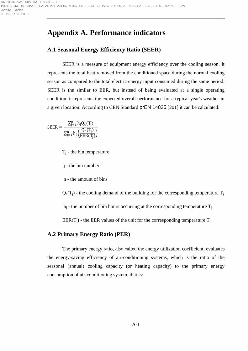
A-1
Appendix A. Performance indicators
A.1 Seasonal Energy Efficiency Ratio (SEER)
SEER is a measure of equipment energy efficiency over the cooling season. It
represents the total heat removed from the conditioned space during the normal cooling
season as compared to the total electric energy input consumed during the same period.
SEER is the similar to EER, but instead of being evaluated at a single operating
condition, it represents the expected overall performance for a typical year's weather in
a given location. According to CEN Standard prEN 14825 [201] it can be calculated:
Tj - the bin temperature
j - the bin number
n - the amount of bins
Qc(Tj) - the cooling demand of the building for the corresponding temperature Tj
hj - the number of bin hours occurring at the corresponding temperature Tj
EER(Tj) - the EER values of the unit for the corresponding temperature Tj
A.2 Primary Energy Ratio (PER)
The primary energy ratio, also called the energy utilization coefficient, evaluates
the energy-saving efficiency of air-conditioning systems, which is the ratio of the
seasonal (annual) cooling capacity (or heating capacity) to the primary energy
consumption of air-conditioning system, that is:
UNIVERSITAT ROVIRA I VIRGILI MODELLING OF SMALL CAPACITY ABSORPTION CHILLERS DRIVEN BY SOLAR THERMAL ENERGY OR WASTE HEAT Jerko Labus DL:T.1716-2011
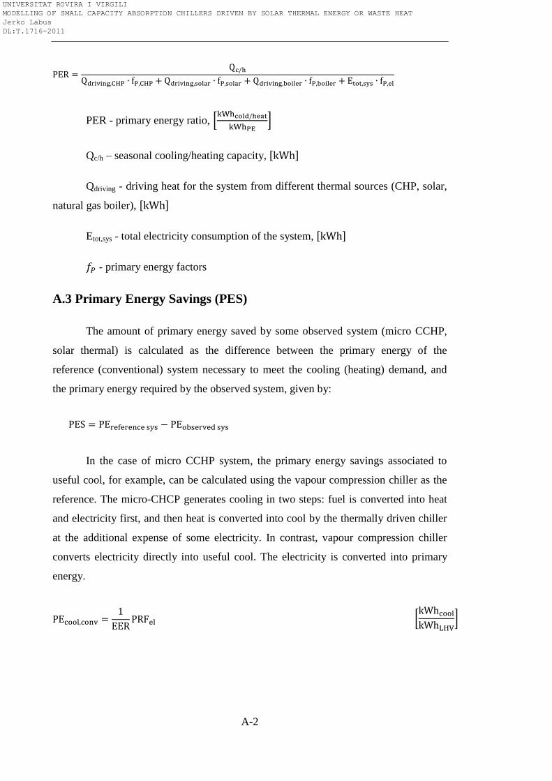
A-2
PER - primary energy ratio,
Qc/h – seasonal cooling/heating capacity,
Qdriving - driving heat for the system from different thermal sources (CHP, solar,
natural gas boiler),
Etot,sys - total electricity consumption of the system,
- primary energy factors
A.3 Primary Energy Savings (PES)
The amount of primary energy saved by some observed system (micro CCHP,
solar thermal) is calculated as the difference between the primary energy of the
reference (conventional) system necessary to meet the cooling (heating) demand, and
the primary energy required by the observed system, given by:
In the case of micro CCHP system, the primary energy savings associated to
useful cool, for example, can be calculated using the vapour compression chiller as the
reference. The micro-CHCP generates cooling in two steps: fuel is converted into heat
and electricity first, and then heat is converted into cool by the thermally driven chiller
at the additional expense of some electricity. In contrast, vapour compression chiller
converts electricity directly into useful cool. The electricity is converted into primary
energy.
UNIVERSITAT ROVIRA I VIRGILI MODELLING OF SMALL CAPACITY ABSORPTION CHILLERS DRIVEN BY SOLAR THERMAL ENERGY OR WASTE HEAT Jerko Labus DL:T.1716-2011
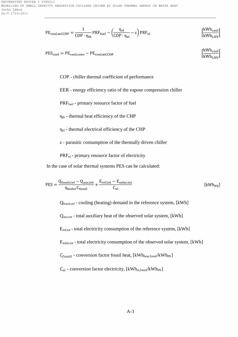
A-3
COP - chiller thermal coefficient of performance
EER - energy efficiency ratio of the vapour compression chiller
PRFfuel - primary resource factor of fuel
ηth - thermal heat efficiency of the CHP
ηel - thermal electrical efficiency of the CHP
ε - parasitic consumption of the thermally driven chiller
PRFel - primary resource factor of electricity
In the case of solar thermal systems PES can be calculated:
Qfossil,ref - cooling (heating) demand in the reference system, [kWh]
Qaux,tot - total auxiliary heat of the observed solar system, [kWh]
Eref,tot - total electricity consumption of the reference system, [kWh]
Esolar,tot - total electricity consumption of the observed solar system, [kWh]
- conversion factor fossil heat, [kWhheat,fossil/kWhPE]
- conversion factor electricity, [kWhel,fossil/kWhPE]
UNIVERSITAT ROVIRA I VIRGILI MODELLING OF SMALL CAPACITY ABSORPTION CHILLERS DRIVEN BY SOLAR THERMAL ENERGY OR WASTE HEAT Jerko Labus DL:T.1716-2011
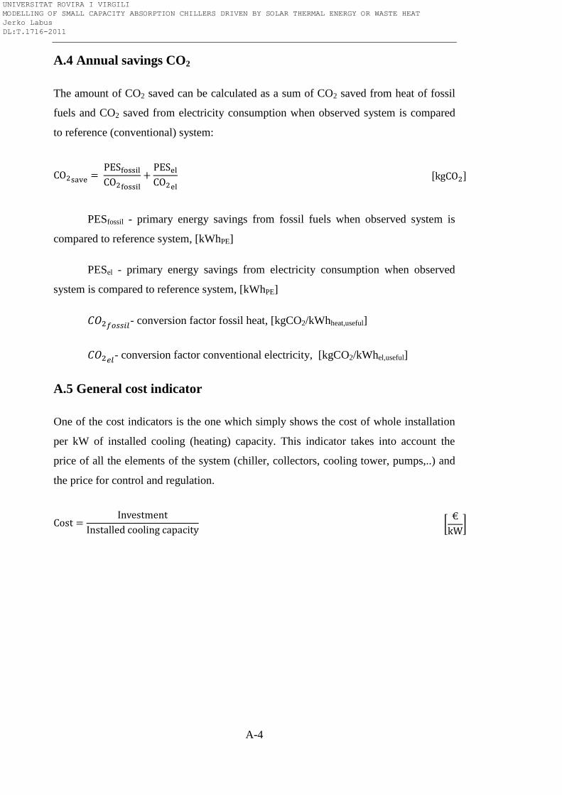
A-4
A.4 Annual savings CO2
The amount of CO2 saved can be calculated as a sum of CO2 saved from heat of fossil
fuels and CO2 saved from electricity consumption when observed system is compared
to reference (conventional) system:
PESfossil - primary energy savings from fossil fuels when observed system is
compared to reference system, [kWhPE]
PESel - primary energy savings from electricity consumption when observed
system is compared to reference system, [kWhPE]
- conversion factor fossil heat, [kgCO2/kWhheat,useful]
- conversion factor conventional electricity, [kgCO2/kWhel,useful]
A.5 General cost indicator
One of the cost indicators is the one which simply shows the cost of whole installation
per kW of installed cooling (heating) capacity. This indicator takes into account the
price of all the elements of the system (chiller, collectors, cooling tower, pumps,..) and
the price for control and regulation.
UNIVERSITAT ROVIRA I VIRGILI MODELLING OF SMALL CAPACITY ABSORPTION CHILLERS DRIVEN BY SOLAR THERMAL ENERGY OR WASTE HEAT Jerko Labus DL:T.1716-2011
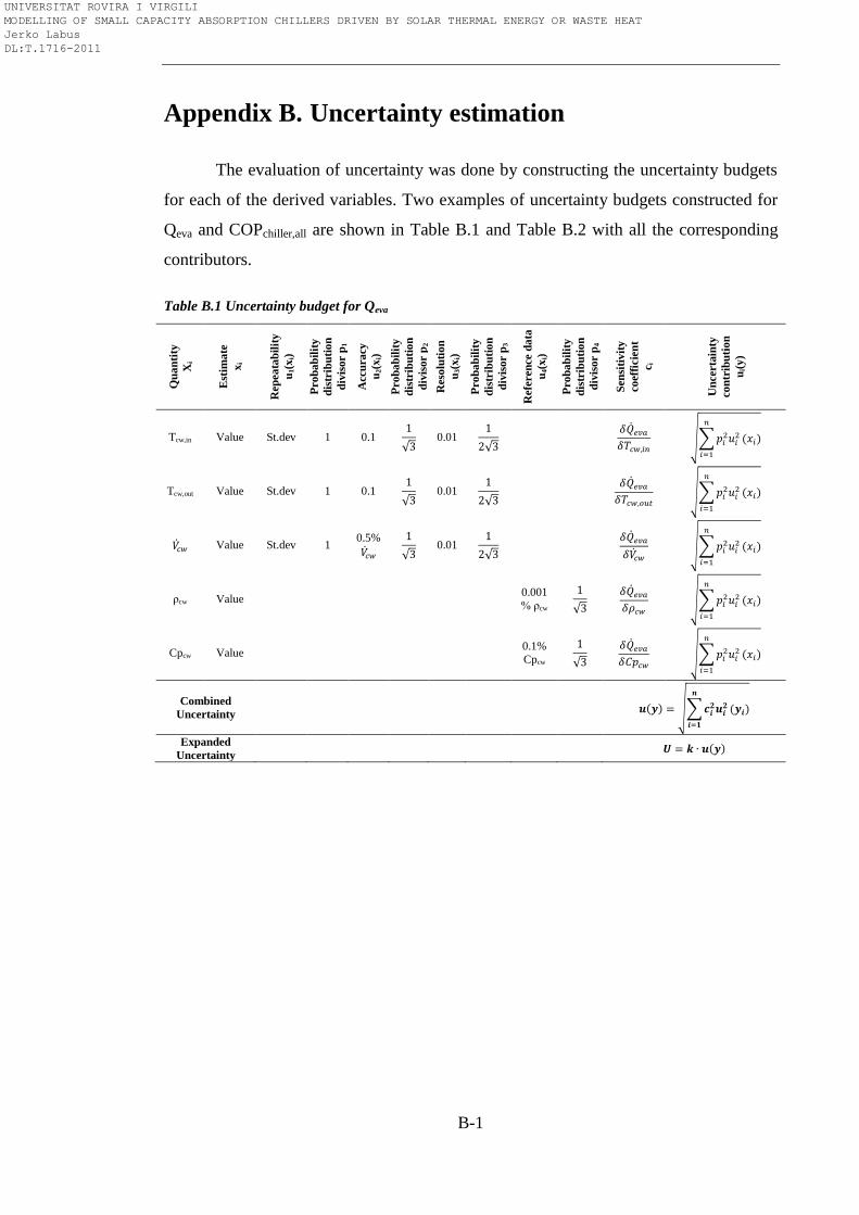
B-1
Appendix B. Uncertainty estimation
The evaluation of uncertainty was done by constructing the uncertainty budgets
for each of the derived variables. Two examples of uncertainty budgets constructed for
Qeva and COPchiller,all are shown in Table B.1 and Table B.2 with all the corresponding
contributors.
Table B.1 Uncertainty budget for Qeva
Qu
an
tity
Xi
Est
ima
te
xi
Rep
ea
tab
ilit
y
u1(x
i)
Pro
ba
bil
ity
dis
trib
uti
on
div
isor p
1
Accu
racy
u2(x
i)
Pro
ba
bil
ity
dis
trib
uti
on
div
isor p
2
Reso
luti
on
u3(x
i)
Pro
ba
bil
ity
dis
trib
uti
on
div
isor p
3
Refe
ren
ce d
ata
u4(x
i)
Pro
ba
bil
ity
dis
trib
uti
on
div
isor p
4
Sen
siti
vit
y
co
eff
icie
nt
ci
Un
certa
inty
co
ntr
ibu
tio
n
ui(
y)
Tcw,in Value St.dev 1 0.1
0.01
Tcw,out Value St.dev 1 0.1
0.01
Value St.dev 1 0.5%
0.01
ρcw Value 0.001
% ρcw
Cpcw Value 0.1%
Cpcw
Combined
Uncertainty
Expanded
Uncertainty
UNIVERSITAT ROVIRA I VIRGILI MODELLING OF SMALL CAPACITY ABSORPTION CHILLERS DRIVEN BY SOLAR THERMAL ENERGY OR WASTE HEAT Jerko Labus DL:T.1716-2011
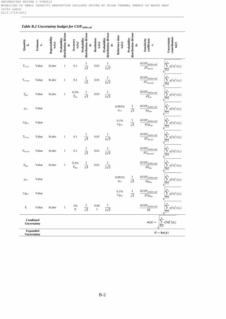
B-2
Table B.2 Uncertainty budget for COPchiller,all Q
ua
nti
ty
Xi
Est
ima
te
xi
Rep
ea
tab
ilit
y
u1(x
i)
Pro
ba
bil
ity
dis
trib
uti
on
div
isor
p1
Accu
racy
u2(x
i)
Pro
ba
bil
ity
dis
trib
uti
on
div
isor
p2
Reso
luti
on
u3(x
i)
Pro
ba
bil
ity
dis
trib
uti
on
div
isor
p3
Refe
ren
ce d
ata
u4(x
i)
Pro
ba
bil
ity
dis
trib
uti
on
div
isor
p4
Sen
siti
vit
y
co
eff
icie
nt
ci
Un
certa
inty
co
ntr
ibu
tio
n
ui(
y)
Tcw,in Value St.dev 1 0.1
0.01
Tcw,out Value St.dev 1 0.1
0.01
Value St.dev 1 0.5%
0.01
ρcw Value 0.001%
ρcw
Cpcw Value 0.1%
Cpcw
Thw,in Value St.dev 1 0.1
0.01
Thw,out Value St.dev 1 0.1
0.01
Value St.dev 1 0.5%
0.01
ρhw Value 0.001%
ρhw
Cphw Value 0.1%
Cphw
E Value St.dev 1 1% E
0.001
Combined
Uncertainty
Expanded
Uncertainty
UNIVERSITAT ROVIRA I VIRGILI MODELLING OF SMALL CAPACITY ABSORPTION CHILLERS DRIVEN BY SOLAR THERMAL ENERGY OR WASTE HEAT Jerko Labus DL:T.1716-2011
C-1
Appendix C. Steady state identification
C.1 Literature review
Optimization, control and process performance assessment are strongly
dependant on steady-state detection. The use of steady-state identification and
simulation techniques is fundamental in several fields such as: process optimization,
fault detection, performance assessment, gross error detection, sensor analysis, data
reconciliation and empirical models built with regression or ANN. The data for such
models should be collected in steady-state conditions, otherwise entire modelling can
lead to failure. Usually, the information about steady-state identification when post-
processing the experimental or whatever process measurements in order to develop
accurate steady-state models is very scarce or even omitted in open literature. The
adaptation of models to data obtained exclusively in steady-state operation leads to
better solutions. Before proceeding, we should define what steady-state is, because this
term can mislead. It is not ―stationary‖ like in statistics, because there is no process
parameter which is ever steady, but a process with parameters maintaining within some
previously established thresholds. The steady-state identification can be on-line or off-
line, depending on purpose of application. The analysis of real data is complex because
they include stochastic component and, therefore, the use of statistical methods is
necessary to perform the task.
The most common methods for steady-state identification are based on
calculating either the mean, variance or regression slope over a data window and
performing the statistical test such as t-test. Generally, all the statistical methods tend to
reduce type I and II errors. Type I error is the error of rejecting the null hypothesis (not
at steady-state) when it is actually true. Type II error is the error of failing to reject the
null hypothesis when it should be rejected. Despite the existence of different steady-
state detection procedures, one cannot say with assurance which provides the best
results. The following section provides a literature review on different steady-state
detection techniques, trying to highlight the advantages and disadvantages in order to
find the optimal and the simplest to apply it for absorption equipment.
UNIVERSITAT ROVIRA I VIRGILI MODELLING OF SMALL CAPACITY ABSORPTION CHILLERS DRIVEN BY SOLAR THERMAL ENERGY OR WASTE HEAT Jerko Labus DL:T.1716-2011
C-2
Narasimhan et al. [202] proposed a composite statistical test to detect when
process variables change steady-states. It is well-known fact in multivariate statistics
that the distribution arises with the differences between the means of different
populations. Thus, the authors suggested comparing the covariance matrices in two
consecutive time periods. Hotelling T2 method (which is the multivariate counterpart of
Student’s t-distribution) would be performed to check whether the periods have equal
means in case when the covariance matrices are the same. Conversely, in case when the
covariance matrices are unequal, non central T2 test is performed. This method assumes
that only random errors exist with zero means, and successive periods of time are
assumed to be steady. A change of steady-state may occur from one period to the next,
but within each period the process is in steady-state. Narasimhan and co-workers [203]
also suggested a test for detecting changes in steady state by using the mathematical
theory of evidence. A key element of this method is the assignment of beliefs to the
different propositions of interest. Since this usually involves subjective judgement, the
authors used the probabilities from the T2 distribution to assign beliefs that process is at
steady state, non-steady state, and uncertain. Hotelling T2-statistic is used again, defined
by comparing the difference of means between periods to the variability within the
periods. In addition, the results of simulation analysis in the same study showed that
both methods (composite statistical test and method with mathematical theory of
evidence) have the same performance. However, in practice is not so easy to find
successive time periods within which process variables are in steady state. Hence, it is
very difficult to satisfy this specific assumption for both methods. The Type I error of
the composite test is theoretically independent of the number of variables and period
size. However, in practice it was found to be strongly dependent on both the number of
variables and period size when applied to plant data.
In 1994 three papers were addressed to the topic how to detect steady-state
conditions automatically. Loar [204] suggested a moving average chart with thresholds
of ±3s. When the moving average breaks the thresholds value, the alarm indicates that
some irregularity has occurred. However, this method cannot indicate steady-state; it is
used to trigger control. Another method [205] compares the average from a recent
history to a "standard" based on an earlier history and then use t-statistic test to check if
the average changed. A problem of this approach is that the steady-state hypothesis and
UNIVERSITAT ROVIRA I VIRGILI MODELLING OF SMALL CAPACITY ABSORPTION CHILLERS DRIVEN BY SOLAR THERMAL ENERGY OR WASTE HEAT Jerko Labus DL:T.1716-2011
C-3
equal mean are quite different. If the process is oscillating and the data window happens
to bracket the "standard" mean, then the t-test could accept the equal mean hypothesis
when, in fact, the process steady-state hypothesis should be rejected. On the other hand,
data storage and data processing are computational burden. The third method reported
by Jubien and Bihary [206] is based on calculating the standard deviation of selected
process variables over a moving window of recent data period. The measured standard
deviation must be within some established limits; otherwise, not at steady-state
condition is triggered. The success of the method depends on the process variables time
period, selection of process variables and the ―threshold‖ standard deviation. Same as
previous, this method is computational burden.
Glass et al. [207] in their study on fault detection in air-handling units control
the steady-state behaviour of the system by mixing the outside air with return air to
ensure that the temperature of the mixed air is closed to the supply air set-point
temperature. It is considered that the system operates in steady-state conditions if the
fraction of outside air in the mix is within constrained bounds. The geometrically
weighted variance is used to identify steady state, where the older data are removed by
multiplication with forgetting factor based on time constant. In other words, the steady
state identification is based on very simple approach, defining the upper and down
limits using user’s expertise.
Cao and Rhinehart [208, 209] developed a new method for the on-line
identification of steady-state. Their method uses critical values of an F-like test applied
to the ratio of two different estimates of variances of data time series. When the ratio
(evaluated at each time step) is close to one, the process can be considered as steady-
state. The first estimate of variance is based on the filtered squared deviation from
previous filtered value while the second estimate is based on filtered square differences
of successive data. Each of the estimates of variances is calculated using a conventional
exponentially weighted moving average or conventional first-order filter in order to
replace the sample mean. In this way, moving data windows are avoided and
consequently storage and computational requirements are reduced. The filter factors λ1,
λ2 and λ3, varying from 0 to 1, must be tuned empirically in order to allow the
minimization of type I and type II errors. The authors presented a short note about the
UNIVERSITAT ROVIRA I VIRGILI MODELLING OF SMALL CAPACITY ABSORPTION CHILLERS DRIVEN BY SOLAR THERMAL ENERGY OR WASTE HEAT Jerko Labus DL:T.1716-2011
C-4
critical values [210]. The filter factors values are set based on the relevance of the actual
values in comparison to the past ones, and could be interpreted as forgetting factors
expressing something analogue to a window size. Although Cao and Rhinehart method
can perform at any point of time, time delay is still present as well as the insensitivity to
changes due to use of filtering techniques. Also, the adequate selection of the filter
factors (which is empirical) requires a certain amount of experience.
Önöz and Bayazit [211] compared the t-test for trend detection with Mann-
Kendall’s test. The results of a simulations showed that the t-test is slightly more
powerful when the probability distribution is normal, while for moderately skewed
distribution Mann-Kendall test gives slightly better results. The authors’ conclusion is
that these two tests can be used interchangeably in practical applications.
A development of steady-state identifier for industrial process units was also
addressed in two papers of Bhat and co-authors [212, 213]. Actually, the authors
applied the method of Cao and Rhinehart with some modifications. These modifications
are related to optimization of the exponential filter constants. This optimization is based
on minimizing the delay to identify steady-state or unsteady-state, minimizing at the
same time type I and II errors. However, this optimization is empirical (trial and error)
since there are not analytical relationship between the exponential filter constant and the
delay time and type I and II errors.
Jiang et al. [214] proposed a method for steady-state detection in continuous
processes based on wavelet transform. Multi-scale wavelet processing technique was
used to remove random noise and non-random errors extracting the process trends from
raw measurements. The process status is measured using an index ranging from 0 to 1
according to the wavelet transform modulus indicating steady-state if its value is close
to zero. Although authors demonstrated this method can be implemented on-line in
crude oil unit, there are several problems which must be addressed. Real-time data have
to be truncated to fit the window size, the determination of characteristic scale for
steady state detection, boundary effects are introduced since the wavelet transform is
carried out with finite dimension data set and there is a time delay. The solution,
according to the authors, is to use a symmetric extent technique. However, the method
seems to be mathematically very complex and the same authors emphasize the
UNIVERSITAT ROVIRA I VIRGILI MODELLING OF SMALL CAPACITY ABSORPTION CHILLERS DRIVEN BY SOLAR THERMAL ENERGY OR WASTE HEAT Jerko Labus DL:T.1716-2011
C-5
importance of the experience with the process being considered. The experience and the
data treatment method to determine key parameters such as the threshold values and the
degree of the contribution from the second-order wavelet transform.
Regression is a useful technique in data analysis when one or more variables
influence or affect a second or multiple variables. This method belongs to a group of
so-called direct approaches. Normally, it consists in performing linear regression over a
data window and then to use a t-test on the regression slope. For a given sample size
and confidence interval, the calculated t values are compared with critical values of t in
a standard table. If the hypothesis that there is no correlation between the x and y
variables is not rejected at the chosen level of significance, the slope of the line cannot
be shown to differ statistically from zero. This can be statistically considered as a
steady-state in the y-variable. The examples of this approach can be found in the paper
of Schladt and Hu [215] and in thesis of Pilar Moreno [216]. Schladt and Hu used t-
test-type steady-state check by comparing the mean values of two subsequent time
intervals. Pilar Moreno in her thesis performed the least square linear regression over a
moving data window in order to find the equation of the best-fitting line for a set of
data, and to analyze the rate-of-change of the line reflected in the slope. Steady-state can
be identified if the slope is smaller than the threshold for several samples. The threshold
in this case is not a constant but a function which depends on set point change and
standard deviation of the noise. Another parameter, the size of the moving window
depends upon the time constant of the variable and not on sampling time, which is usual
practice.
Kim et al. [138] developed a steady-state detector for fault detection and
diagnosis of vapour compression system based on moving window and using standard
deviation of seven selected variables. The threshold value of three standard deviations
(±3s) was selected as boundary within which the variable is considered to be in steady-
state. The standard deviations of each variable were calculated based on three repeated
measurements of the start-up transient tests. Again, the problem which usually follows
moving window methods is time delay which can cause that some of the transient
periods escape filtering. Another disadvantage is the optimum size of the moving
UNIVERSITAT ROVIRA I VIRGILI MODELLING OF SMALL CAPACITY ABSORPTION CHILLERS DRIVEN BY SOLAR THERMAL ENERGY OR WASTE HEAT Jerko Labus DL:T.1716-2011
C-6
window which has to be determined empirically and which depends upon the system
controller and instrumentation.
Le Roux et al. [217] in their study compared four different steady-state
identification methods: modified F-test (Cao and Rhinehart), Reverse Arrangements
Test, Rank von Newman Test and Polynomial Interpolation Test (based on Sawitzky
and Golay algorithm [218]). Using a Monte-Carlo simulation and data from crude oil
distillation unit the authors drove a conclusion that for simulated data Polynomial
Interpolation Test performs better than the other tests considered.
Some other statistical methods like Wald-Wolowitz Runs test, the Mann-
Kendall or Principal Component Analysis were also mentioned in a literature [215, 219]
as a possibility for steady-state identification, but the practical application was not
found.
As can be seen from this review, there are different methods which can be
applied for steady-state identification. All of them have their cons and pros which
depend on type of application and purpose. For off-line identification the moving
window charts are usually the most suitable solution while for on-line identification in
process plant more suitable are methods such as Cao and Rhinehart modified F-test or
Polynomial Interpolation Test which are not computational burden. On the other hand,
these tests can be mathematically very complex requiring some additional filter factors
and very often some user expertise. Very often there is a problem with time-delay when
detecting changes from steady-state to transient conditions. Therefore, when choosing a
method for steady-state identification, one should make a balance between the purpose
of the application and the complexity of the detector. Usually, in different system
applications or experimental set ups such as URV multifunctional test bench, absorption
equipment is already controlled through the external circuit temperatures and flow rates.
The use of steady-state detectors is hence off-line, when post-processing the data which
will further be used in model development. The steady-state detector developed in this
thesis is based on moving window methodology, the modified methodology for
absorption equipment of the one proposed by Kim et al. [138]. The problem with
additional remaining transients periods caused by time delays when changing from one
UNIVERSITAT ROVIRA I VIRGILI MODELLING OF SMALL CAPACITY ABSORPTION CHILLERS DRIVEN BY SOLAR THERMAL ENERGY OR WASTE HEAT Jerko Labus DL:T.1716-2011
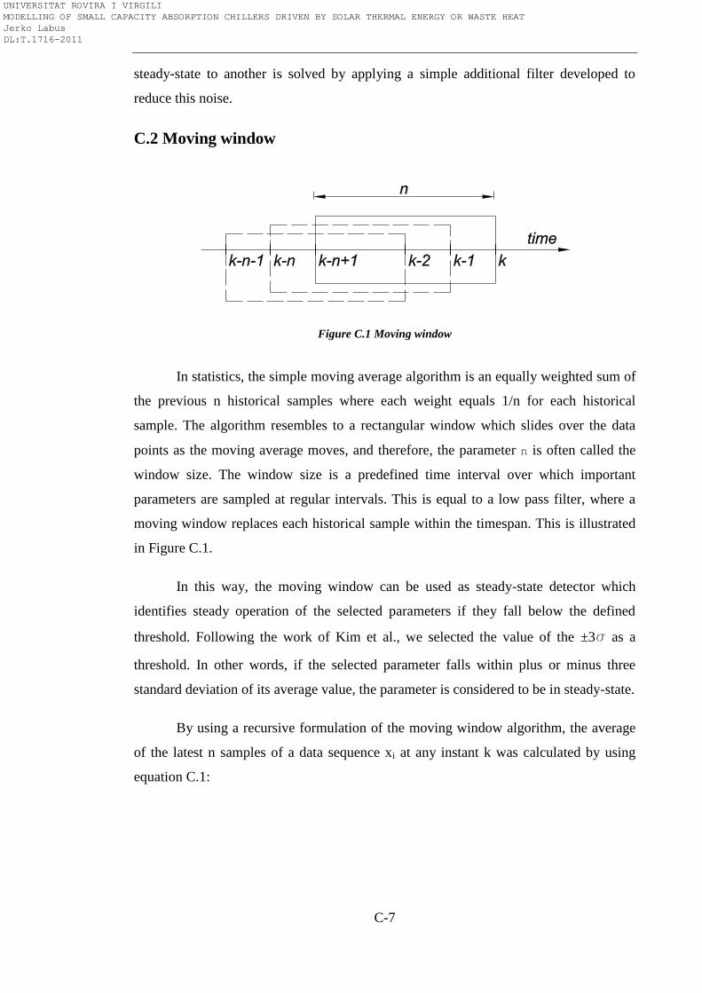
C-7
steady-state to another is solved by applying a simple additional filter developed to
reduce this noise.
C.2 Moving window
Figure C.1 Moving window
In statistics, the simple moving average algorithm is an equally weighted sum of
the previous n historical samples where each weight equals 1/n for each historical
sample. The algorithm resembles to a rectangular window which slides over the data
points as the moving average moves, and therefore, the parameter n is often called the
window size. The window size is a predefined time interval over which important
parameters are sampled at regular intervals. This is equal to a low pass filter, where a
moving window replaces each historical sample within the timespan. This is illustrated
in Figure C.1.
In this way, the moving window can be used as steady-state detector which
identifies steady operation of the selected parameters if they fall below the defined
threshold. Following the work of Kim et al., we selected the value of the ±3s as a
threshold. In other words, if the selected parameter falls within plus or minus three
standard deviation of its average value, the parameter is considered to be in steady-state.
By using a recursive formulation of the moving window algorithm, the average
of the latest n samples of a data sequence xi at any instant k was calculated by using
equation C.1:
UNIVERSITAT ROVIRA I VIRGILI MODELLING OF SMALL CAPACITY ABSORPTION CHILLERS DRIVEN BY SOLAR THERMAL ENERGY OR WASTE HEAT Jerko Labus DL:T.1716-2011
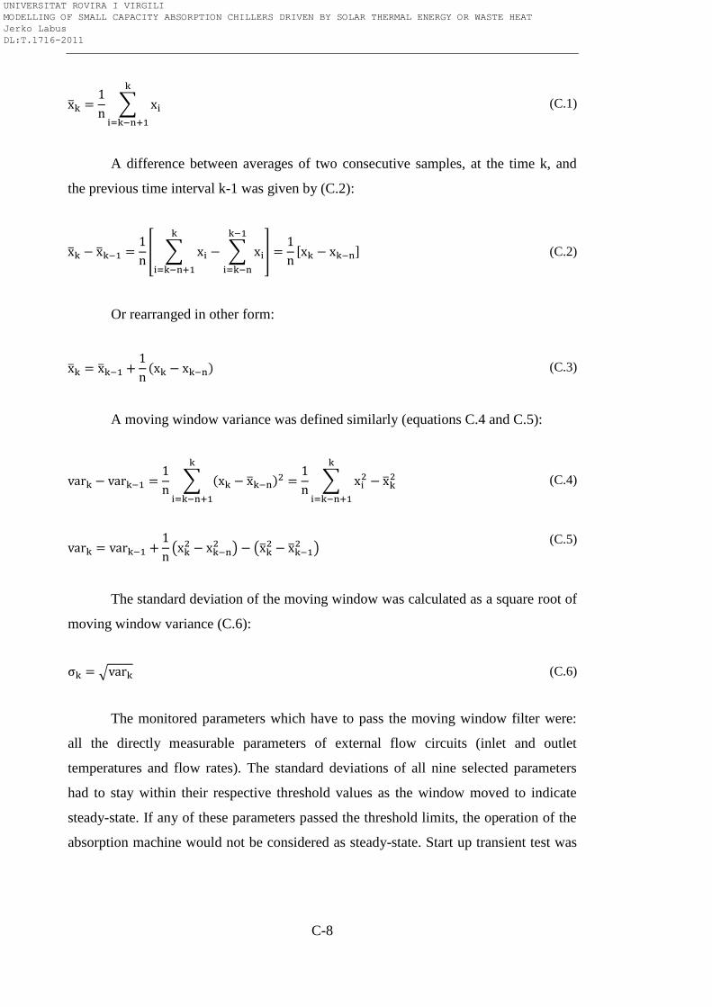
C-8
(C.1)
A difference between averages of two consecutive samples, at the time k, and
the previous time interval k-1 was given by (C.2):
(C.2)
Or rearranged in other form:
(C.3)
A moving window variance was defined similarly (equations C.4 and C.5):
(C.4)
(C.5)
The standard deviation of the moving window was calculated as a square root of
moving window variance (C.6):
(C.6)
The monitored parameters which have to pass the moving window filter were:
all the directly measurable parameters of external flow circuits (inlet and outlet
temperatures and flow rates). The standard deviations of all nine selected parameters
had to stay within their respective threshold values as the window moved to indicate
steady-state. If any of these parameters passed the threshold limits, the operation of the
absorption machine would not be considered as steady-state. Start up transient test was
UNIVERSITAT ROVIRA I VIRGILI MODELLING OF SMALL CAPACITY ABSORPTION CHILLERS DRIVEN BY SOLAR THERMAL ENERGY OR WASTE HEAT Jerko Labus DL:T.1716-2011
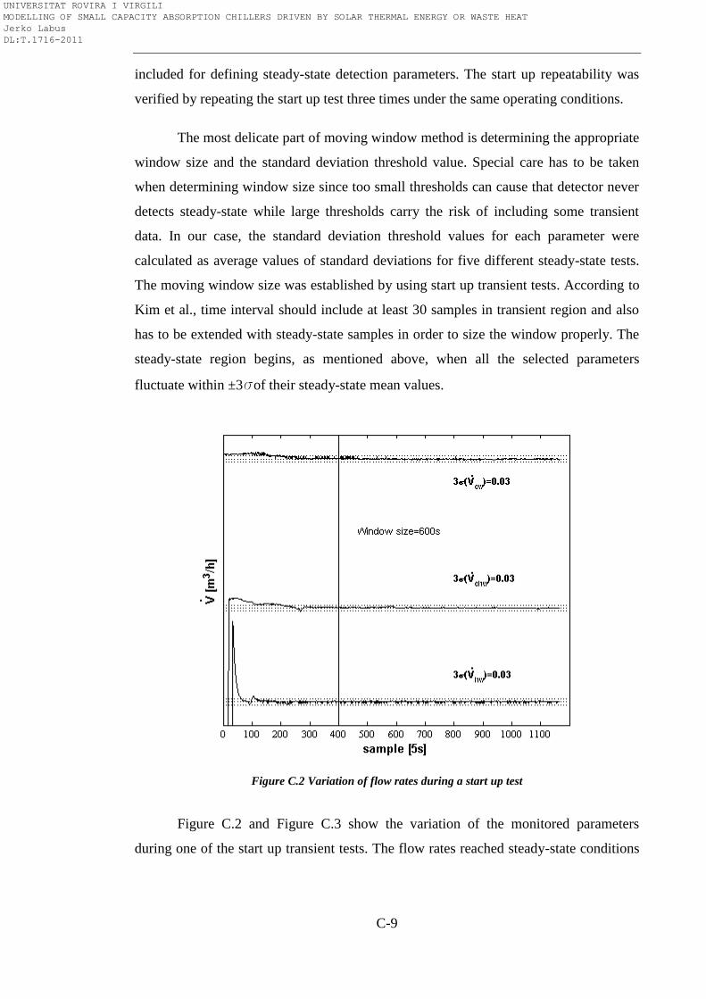
C-9
included for defining steady-state detection parameters. The start up repeatability was
verified by repeating the start up test three times under the same operating conditions.
The most delicate part of moving window method is determining the appropriate
window size and the standard deviation threshold value. Special care has to be taken
when determining window size since too small thresholds can cause that detector never
detects steady-state while large thresholds carry the risk of including some transient
data. In our case, the standard deviation threshold values for each parameter were
calculated as average values of standard deviations for five different steady-state tests.
The moving window size was established by using start up transient tests. According to
Kim et al., time interval should include at least 30 samples in transient region and also
has to be extended with steady-state samples in order to size the window properly. The
steady-state region begins, as mentioned above, when all the selected parameters
fluctuate within ±3sof their steady-state mean values.
Figure C.2 Variation of flow rates during a start up test
Figure C.2 and Figure C.3 show the variation of the monitored parameters
during one of the start up transient tests. The flow rates reached steady-state conditions
UNIVERSITAT ROVIRA I VIRGILI MODELLING OF SMALL CAPACITY ABSORPTION CHILLERS DRIVEN BY SOLAR THERMAL ENERGY OR WASTE HEAT Jerko Labus DL:T.1716-2011
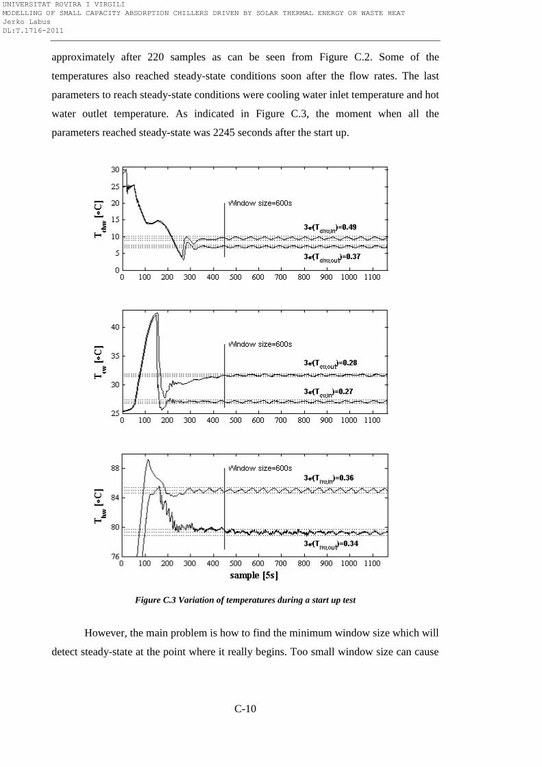
C-10
approximately after 220 samples as can be seen from Figure C.2. Some of the
temperatures also reached steady-state conditions soon after the flow rates. The last
parameters to reach steady-state conditions were cooling water inlet temperature and hot
water outlet temperature. As indicated in Figure C.3, the moment when all the
parameters reached steady-state was 2245 seconds after the start up.
Figure C.3 Variation of temperatures during a start up test
However, the main problem is how to find the minimum window size which will
detect steady-state at the point where it really begins. Too small window size can cause
UNIVERSITAT ROVIRA I VIRGILI MODELLING OF SMALL CAPACITY ABSORPTION CHILLERS DRIVEN BY SOLAR THERMAL ENERGY OR WASTE HEAT Jerko Labus DL:T.1716-2011
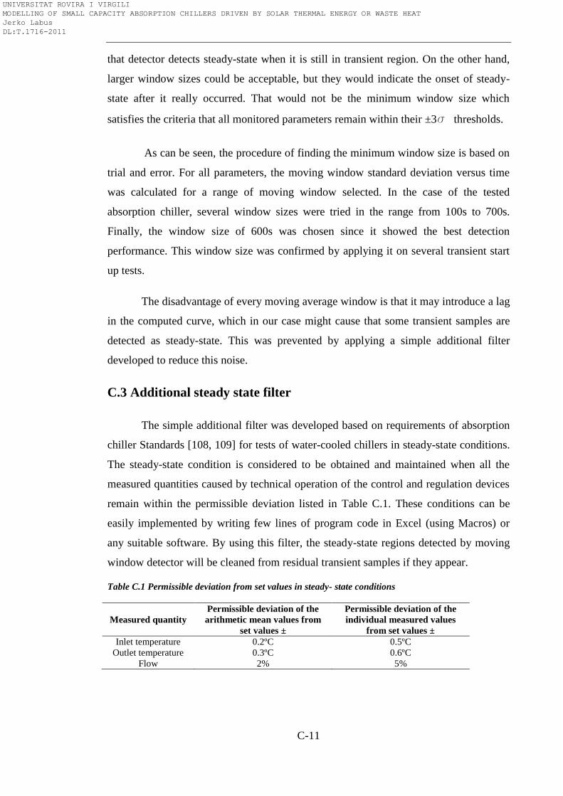
C-11
that detector detects steady-state when it is still in transient region. On the other hand,
larger window sizes could be acceptable, but they would indicate the onset of steady-
state after it really occurred. That would not be the minimum window size which
satisfies the criteria that all monitored parameters remain within their ±3s thresholds.
As can be seen, the procedure of finding the minimum window size is based on
trial and error. For all parameters, the moving window standard deviation versus time
was calculated for a range of moving window selected. In the case of the tested
absorption chiller, several window sizes were tried in the range from 100s to 700s.
Finally, the window size of 600s was chosen since it showed the best detection
performance. This window size was confirmed by applying it on several transient start
up tests.
The disadvantage of every moving average window is that it may introduce a lag
in the computed curve, which in our case might cause that some transient samples are
detected as steady-state. This was prevented by applying a simple additional filter
developed to reduce this noise.
C.3 Additional steady state filter
The simple additional filter was developed based on requirements of absorption
chiller Standards [108, 109] for tests of water-cooled chillers in steady-state conditions.
The steady-state condition is considered to be obtained and maintained when all the
measured quantities caused by technical operation of the control and regulation devices
remain within the permissible deviation listed in Table C.1. These conditions can be
easily implemented by writing few lines of program code in Excel (using Macros) or
any suitable software. By using this filter, the steady-state regions detected by moving
window detector will be cleaned from residual transient samples if they appear.
Table C.1 Permissible deviation from set values in steady- state conditions
Measured quantity
Permissible deviation of the
arithmetic mean values from
set values ±
Permissible deviation of the
individual measured values
from set values ±
Inlet temperature 0.2ºC 0.5ºC
Outlet temperature 0.3ºC 0.6ºC
Flow 2% 5%
UNIVERSITAT ROVIRA I VIRGILI MODELLING OF SMALL CAPACITY ABSORPTION CHILLERS DRIVEN BY SOLAR THERMAL ENERGY OR WASTE HEAT Jerko Labus DL:T.1716-2011
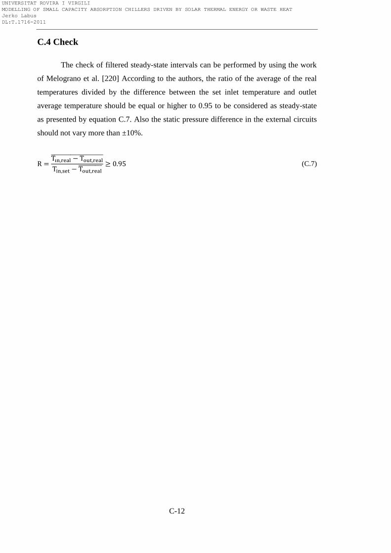
C-12
C.4 Check
The check of filtered steady-state intervals can be performed by using the work
of Melograno et al. [220] According to the authors, the ratio of the average of the real
temperatures divided by the difference between the set inlet temperature and outlet
average temperature should be equal or higher to 0.95 to be considered as steady-state
as presented by equation C.7. Also the static pressure difference in the external circuits
should not vary more than ±10%.
(C.7)
UNIVERSITAT ROVIRA I VIRGILI MODELLING OF SMALL CAPACITY ABSORPTION CHILLERS DRIVEN BY SOLAR THERMAL ENERGY OR WASTE HEAT Jerko Labus DL:T.1716-2011
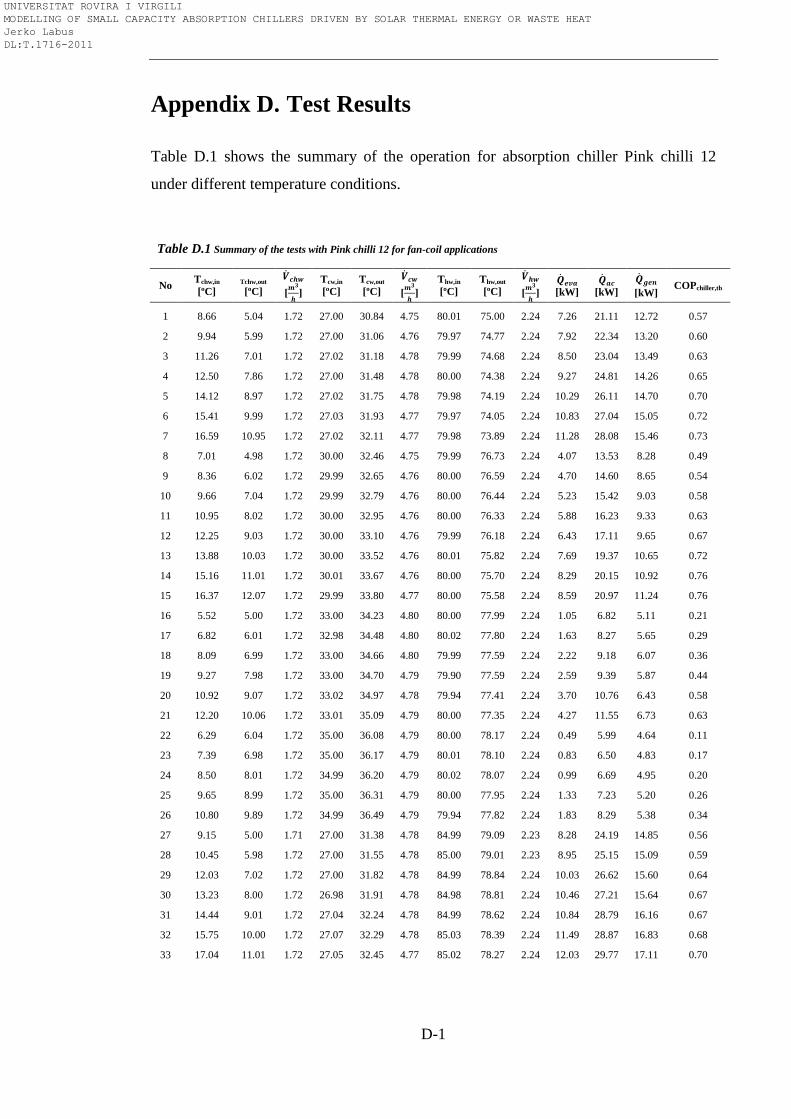
D-1
Appendix D. Test Results
Table D.1 shows the summary of the operation for absorption chiller Pink chilli 12
under different temperature conditions.
Table D.1 Summary of the tests with Pink chilli 12 for fan-coil applications
No Tchw,in
[ºC] Tchw,out
[ºC]
[
]
Tcw,in
[ºC]
Tcw,out
[ºC]
[
]
Thw,in
[ºC]
Thw,out
[ºC]
[
]
[kW]
[kW]
[kW] COPchiller,th
1 8.66 5.04 1.72 27.00 30.84 4.75 80.01 75.00 2.24 7.26 21.11 12.72 0.57
2 9.94 5.99 1.72 27.00 31.06 4.76 79.97 74.77 2.24 7.92 22.34 13.20 0.60
3 11.26 7.01 1.72 27.02 31.18 4.78 79.99 74.68 2.24 8.50 23.04 13.49 0.63
4 12.50 7.86 1.72 27.00 31.48 4.78 80.00 74.38 2.24 9.27 24.81 14.26 0.65
5 14.12 8.97 1.72 27.02 31.75 4.78 79.98 74.19 2.24 10.29 26.11 14.70 0.70
6 15.41 9.99 1.72 27.03 31.93 4.77 79.97 74.05 2.24 10.83 27.04 15.05 0.72
7 16.59 10.95 1.72 27.02 32.11 4.77 79.98 73.89 2.24 11.28 28.08 15.46 0.73
8 7.01 4.98 1.72 30.00 32.46 4.75 79.99 76.73 2.24 4.07 13.53 8.28 0.49
9 8.36 6.02 1.72 29.99 32.65 4.76 80.00 76.59 2.24 4.70 14.60 8.65 0.54
10 9.66 7.04 1.72 29.99 32.79 4.76 80.00 76.44 2.24 5.23 15.42 9.03 0.58
11 10.95 8.02 1.72 30.00 32.95 4.76 80.00 76.33 2.24 5.88 16.23 9.33 0.63
12 12.25 9.03 1.72 30.00 33.10 4.76 79.99 76.18 2.24 6.43 17.11 9.65 0.67
13 13.88 10.03 1.72 30.00 33.52 4.76 80.01 75.82 2.24 7.69 19.37 10.65 0.72
14 15.16 11.01 1.72 30.01 33.67 4.76 80.00 75.70 2.24 8.29 20.15 10.92 0.76
15 16.37 12.07 1.72 29.99 33.80 4.77 80.00 75.58 2.24 8.59 20.97 11.24 0.76
16 5.52 5.00 1.72 33.00 34.23 4.80 80.00 77.99 2.24 1.05 6.82 5.11 0.21
17 6.82 6.01 1.72 32.98 34.48 4.80 80.02 77.80 2.24 1.63 8.27 5.65 0.29
18 8.09 6.99 1.72 33.00 34.66 4.80 79.99 77.59 2.24 2.22 9.18 6.07 0.36
19 9.27 7.98 1.72 33.00 34.70 4.79 79.90 77.59 2.24 2.59 9.39 5.87 0.44
20 10.92 9.07 1.72 33.02 34.97 4.78 79.94 77.41 2.24 3.70 10.76 6.43 0.58
21 12.20 10.06 1.72 33.01 35.09 4.79 80.00 77.35 2.24 4.27 11.55 6.73 0.63
22 6.29 6.04 1.72 35.00 36.08 4.79 80.00 78.17 2.24 0.49 5.99 4.64 0.11
23 7.39 6.98 1.72 35.00 36.17 4.79 80.01 78.10 2.24 0.83 6.50 4.83 0.17
24 8.50 8.01 1.72 34.99 36.20 4.79 80.02 78.07 2.24 0.99 6.69 4.95 0.20
25 9.65 8.99 1.72 35.00 36.31 4.79 80.00 77.95 2.24 1.33 7.23 5.20 0.26
26 10.80 9.89 1.72 34.99 36.49 4.79 79.94 77.82 2.24 1.83 8.29 5.38 0.34
27 9.15 5.00 1.71 27.00 31.38 4.78 84.99 79.09 2.23 8.28 24.19 14.85 0.56
28 10.45 5.98 1.72 27.00 31.55 4.78 85.00 79.01 2.23 8.95 25.15 15.09 0.59
29 12.03 7.02 1.72 27.00 31.82 4.78 84.99 78.84 2.24 10.03 26.62 15.60 0.64
30 13.23 8.00 1.72 26.98 31.91 4.78 84.98 78.81 2.24 10.46 27.21 15.64 0.67
31 14.44 9.01 1.72 27.04 32.24 4.78 84.99 78.62 2.24 10.84 28.79 16.16 0.67
32 15.75 10.00 1.72 27.07 32.29 4.78 85.03 78.39 2.24 11.49 28.87 16.83 0.68
33 17.04 11.01 1.72 27.05 32.45 4.77 85.02 78.27 2.24 12.03 29.77 17.11 0.70
UNIVERSITAT ROVIRA I VIRGILI MODELLING OF SMALL CAPACITY ABSORPTION CHILLERS DRIVEN BY SOLAR THERMAL ENERGY OR WASTE HEAT Jerko Labus DL:T.1716-2011
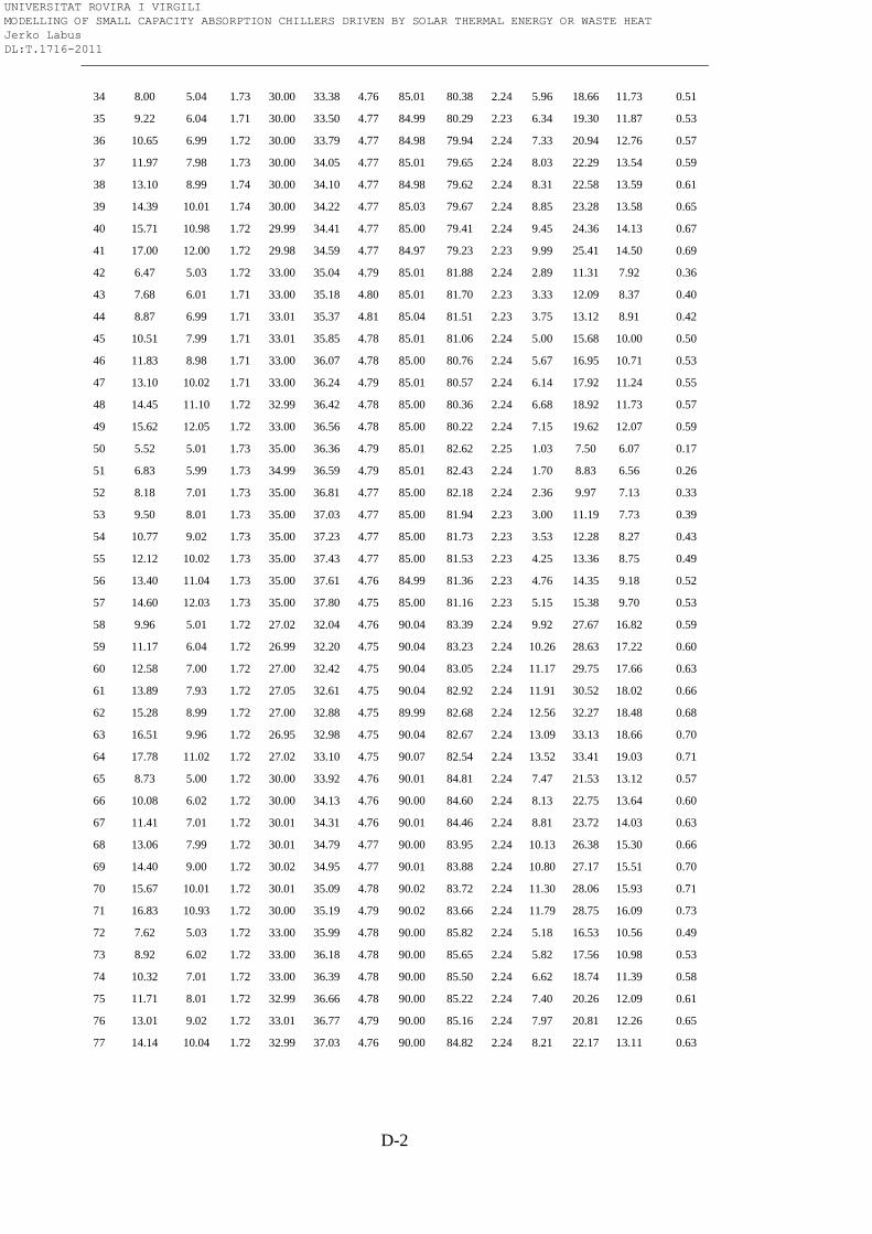
D-2
34 8.00 5.04 1.73 30.00 33.38 4.76 85.01 80.38 2.24 5.96 18.66 11.73 0.51
35 9.22 6.04 1.71 30.00 33.50 4.77 84.99 80.29 2.23 6.34 19.30 11.87 0.53
36 10.65 6.99 1.72 30.00 33.79 4.77 84.98 79.94 2.24 7.33 20.94 12.76 0.57
37 11.97 7.98 1.73 30.00 34.05 4.77 85.01 79.65 2.24 8.03 22.29 13.54 0.59
38 13.10 8.99 1.74 30.00 34.10 4.77 84.98 79.62 2.24 8.31 22.58 13.59 0.61
39 14.39 10.01 1.74 30.00 34.22 4.77 85.03 79.67 2.24 8.85 23.28 13.58 0.65
40 15.71 10.98 1.72 29.99 34.41 4.77 85.00 79.41 2.24 9.45 24.36 14.13 0.67
41 17.00 12.00 1.72 29.98 34.59 4.77 84.97 79.23 2.23 9.99 25.41 14.50 0.69
42 6.47 5.03 1.72 33.00 35.04 4.79 85.01 81.88 2.24 2.89 11.31 7.92 0.36
43 7.68 6.01 1.71 33.00 35.18 4.80 85.01 81.70 2.23 3.33 12.09 8.37 0.40
44 8.87 6.99 1.71 33.01 35.37 4.81 85.04 81.51 2.23 3.75 13.12 8.91 0.42
45 10.51 7.99 1.71 33.01 35.85 4.78 85.01 81.06 2.24 5.00 15.68 10.00 0.50
46 11.83 8.98 1.71 33.00 36.07 4.78 85.00 80.76 2.24 5.67 16.95 10.71 0.53
47 13.10 10.02 1.71 33.00 36.24 4.79 85.01 80.57 2.24 6.14 17.92 11.24 0.55
48 14.45 11.10 1.72 32.99 36.42 4.78 85.00 80.36 2.24 6.68 18.92 11.73 0.57
49 15.62 12.05 1.72 33.00 36.56 4.78 85.00 80.22 2.24 7.15 19.62 12.07 0.59
50 5.52 5.01 1.73 35.00 36.36 4.79 85.01 82.62 2.25 1.03 7.50 6.07 0.17
51 6.83 5.99 1.73 34.99 36.59 4.79 85.01 82.43 2.24 1.70 8.83 6.56 0.26
52 8.18 7.01 1.73 35.00 36.81 4.77 85.00 82.18 2.24 2.36 9.97 7.13 0.33
53 9.50 8.01 1.73 35.00 37.03 4.77 85.00 81.94 2.23 3.00 11.19 7.73 0.39
54 10.77 9.02 1.73 35.00 37.23 4.77 85.00 81.73 2.23 3.53 12.28 8.27 0.43
55 12.12 10.02 1.73 35.00 37.43 4.77 85.00 81.53 2.23 4.25 13.36 8.75 0.49
56 13.40 11.04 1.73 35.00 37.61 4.76 84.99 81.36 2.23 4.76 14.35 9.18 0.52
57 14.60 12.03 1.73 35.00 37.80 4.75 85.00 81.16 2.23 5.15 15.38 9.70 0.53
58 9.96 5.01 1.72 27.02 32.04 4.76 90.04 83.39 2.24 9.92 27.67 16.82 0.59
59 11.17 6.04 1.72 26.99 32.20 4.75 90.04 83.23 2.24 10.26 28.63 17.22 0.60
60 12.58 7.00 1.72 27.00 32.42 4.75 90.04 83.05 2.24 11.17 29.75 17.66 0.63
61 13.89 7.93 1.72 27.05 32.61 4.75 90.04 82.92 2.24 11.91 30.52 18.02 0.66
62 15.28 8.99 1.72 27.00 32.88 4.75 89.99 82.68 2.24 12.56 32.27 18.48 0.68
63 16.51 9.96 1.72 26.95 32.98 4.75 90.04 82.67 2.24 13.09 33.13 18.66 0.70
64 17.78 11.02 1.72 27.02 33.10 4.75 90.07 82.54 2.24 13.52 33.41 19.03 0.71
65 8.73 5.00 1.72 30.00 33.92 4.76 90.01 84.81 2.24 7.47 21.53 13.12 0.57
66 10.08 6.02 1.72 30.00 34.13 4.76 90.00 84.60 2.24 8.13 22.75 13.64 0.60
67 11.41 7.01 1.72 30.01 34.31 4.76 90.01 84.46 2.24 8.81 23.72 14.03 0.63
68 13.06 7.99 1.72 30.01 34.79 4.77 90.00 83.95 2.24 10.13 26.38 15.30 0.66
69 14.40 9.00 1.72 30.02 34.95 4.77 90.01 83.88 2.24 10.80 27.17 15.51 0.70
70 15.67 10.01 1.72 30.01 35.09 4.78 90.02 83.72 2.24 11.30 28.06 15.93 0.71
71 16.83 10.93 1.72 30.00 35.19 4.79 90.02 83.66 2.24 11.79 28.75 16.09 0.73
72 7.62 5.03 1.72 33.00 35.99 4.78 90.00 85.82 2.24 5.18 16.53 10.56 0.49
73 8.92 6.02 1.72 33.00 36.18 4.78 90.00 85.65 2.24 5.82 17.56 10.98 0.53
74 10.32 7.01 1.72 33.00 36.39 4.78 90.00 85.50 2.24 6.62 18.74 11.39 0.58
75 11.71 8.01 1.72 32.99 36.66 4.78 90.00 85.22 2.24 7.40 20.26 12.09 0.61
76 13.01 9.02 1.72 33.01 36.77 4.79 90.00 85.16 2.24 7.97 20.81 12.26 0.65
77 14.14 10.04 1.72 32.99 37.03 4.76 90.00 84.82 2.24 8.21 22.17 13.11 0.63
UNIVERSITAT ROVIRA I VIRGILI MODELLING OF SMALL CAPACITY ABSORPTION CHILLERS DRIVEN BY SOLAR THERMAL ENERGY OR WASTE HEAT Jerko Labus DL:T.1716-2011
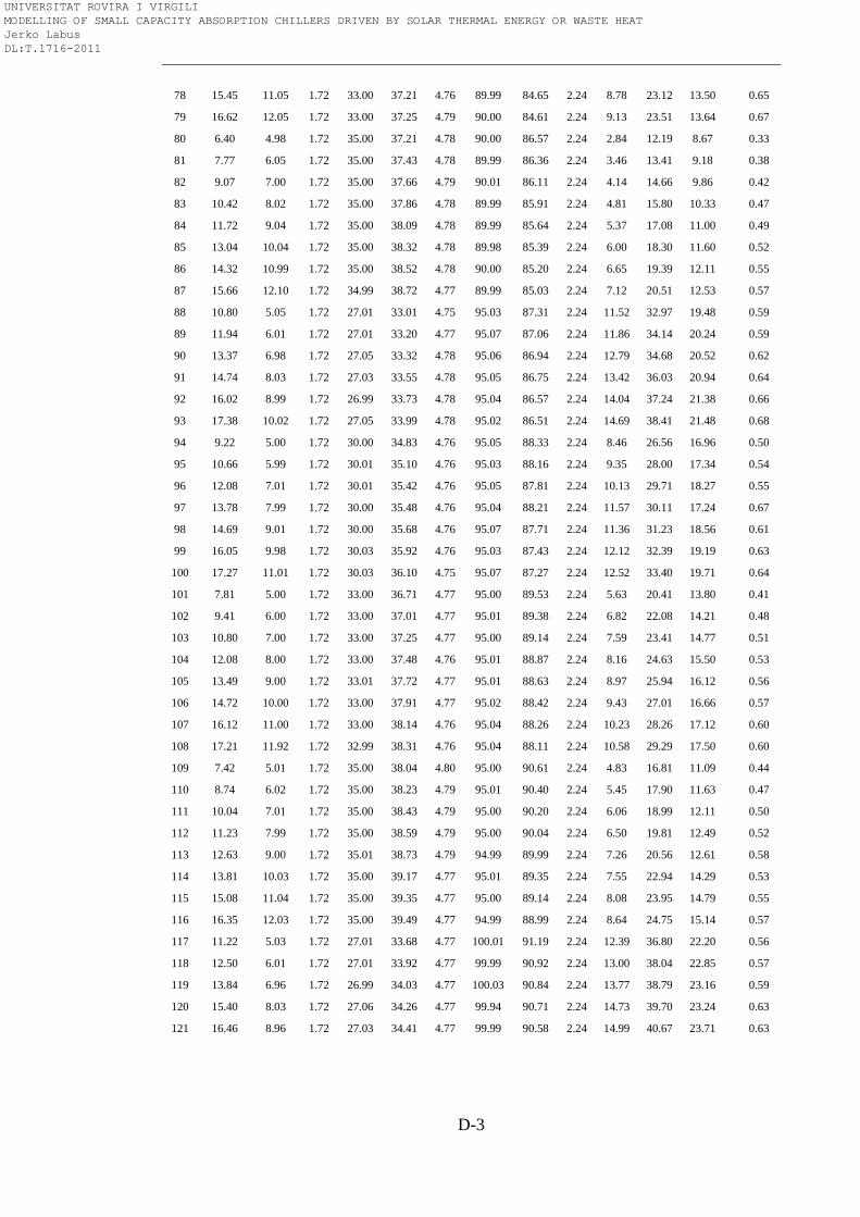
D-3
78 15.45 11.05 1.72 33.00 37.21 4.76 89.99 84.65 2.24 8.78 23.12 13.50 0.65
79 16.62 12.05 1.72 33.00 37.25 4.79 90.00 84.61 2.24 9.13 23.51 13.64 0.67
80 6.40 4.98 1.72 35.00 37.21 4.78 90.00 86.57 2.24 2.84 12.19 8.67 0.33
81 7.77 6.05 1.72 35.00 37.43 4.78 89.99 86.36 2.24 3.46 13.41 9.18 0.38
82 9.07 7.00 1.72 35.00 37.66 4.79 90.01 86.11 2.24 4.14 14.66 9.86 0.42
83 10.42 8.02 1.72 35.00 37.86 4.78 89.99 85.91 2.24 4.81 15.80 10.33 0.47
84 11.72 9.04 1.72 35.00 38.09 4.78 89.99 85.64 2.24 5.37 17.08 11.00 0.49
85 13.04 10.04 1.72 35.00 38.32 4.78 89.98 85.39 2.24 6.00 18.30 11.60 0.52
86 14.32 10.99 1.72 35.00 38.52 4.78 90.00 85.20 2.24 6.65 19.39 12.11 0.55
87 15.66 12.10 1.72 34.99 38.72 4.77 89.99 85.03 2.24 7.12 20.51 12.53 0.57
88 10.80 5.05 1.72 27.01 33.01 4.75 95.03 87.31 2.24 11.52 32.97 19.48 0.59
89 11.94 6.01 1.72 27.01 33.20 4.77 95.07 87.06 2.24 11.86 34.14 20.24 0.59
90 13.37 6.98 1.72 27.05 33.32 4.78 95.06 86.94 2.24 12.79 34.68 20.52 0.62
91 14.74 8.03 1.72 27.03 33.55 4.78 95.05 86.75 2.24 13.42 36.03 20.94 0.64
92 16.02 8.99 1.72 26.99 33.73 4.78 95.04 86.57 2.24 14.04 37.24 21.38 0.66
93 17.38 10.02 1.72 27.05 33.99 4.78 95.02 86.51 2.24 14.69 38.41 21.48 0.68
94 9.22 5.00 1.72 30.00 34.83 4.76 95.05 88.33 2.24 8.46 26.56 16.96 0.50
95 10.66 5.99 1.72 30.01 35.10 4.76 95.03 88.16 2.24 9.35 28.00 17.34 0.54
96 12.08 7.01 1.72 30.01 35.42 4.76 95.05 87.81 2.24 10.13 29.71 18.27 0.55
97 13.78 7.99 1.72 30.00 35.48 4.76 95.04 88.21 2.24 11.57 30.11 17.24 0.67
98 14.69 9.01 1.72 30.00 35.68 4.76 95.07 87.71 2.24 11.36 31.23 18.56 0.61
99 16.05 9.98 1.72 30.03 35.92 4.76 95.03 87.43 2.24 12.12 32.39 19.19 0.63
100 17.27 11.01 1.72 30.03 36.10 4.75 95.07 87.27 2.24 12.52 33.40 19.71 0.64
101 7.81 5.00 1.72 33.00 36.71 4.77 95.00 89.53 2.24 5.63 20.41 13.80 0.41
102 9.41 6.00 1.72 33.00 37.01 4.77 95.01 89.38 2.24 6.82 22.08 14.21 0.48
103 10.80 7.00 1.72 33.00 37.25 4.77 95.00 89.14 2.24 7.59 23.41 14.77 0.51
104 12.08 8.00 1.72 33.00 37.48 4.76 95.01 88.87 2.24 8.16 24.63 15.50 0.53
105 13.49 9.00 1.72 33.01 37.72 4.77 95.01 88.63 2.24 8.97 25.94 16.12 0.56
106 14.72 10.00 1.72 33.00 37.91 4.77 95.02 88.42 2.24 9.43 27.01 16.66 0.57
107 16.12 11.00 1.72 33.00 38.14 4.76 95.04 88.26 2.24 10.23 28.26 17.12 0.60
108 17.21 11.92 1.72 32.99 38.31 4.76 95.04 88.11 2.24 10.58 29.29 17.50 0.60
109 7.42 5.01 1.72 35.00 38.04 4.80 95.00 90.61 2.24 4.83 16.81 11.09 0.44
110 8.74 6.02 1.72 35.00 38.23 4.79 95.01 90.40 2.24 5.45 17.90 11.63 0.47
111 10.04 7.01 1.72 35.00 38.43 4.79 95.00 90.20 2.24 6.06 18.99 12.11 0.50
112 11.23 7.99 1.72 35.00 38.59 4.79 95.00 90.04 2.24 6.50 19.81 12.49 0.52
113 12.63 9.00 1.72 35.01 38.73 4.79 94.99 89.99 2.24 7.26 20.56 12.61 0.58
114 13.81 10.03 1.72 35.00 39.17 4.77 95.01 89.35 2.24 7.55 22.94 14.29 0.53
115 15.08 11.04 1.72 35.00 39.35 4.77 95.00 89.14 2.24 8.08 23.95 14.79 0.55
116 16.35 12.03 1.72 35.00 39.49 4.77 94.99 88.99 2.24 8.64 24.75 15.14 0.57
117 11.22 5.03 1.72 27.01 33.68 4.77 100.01 91.19 2.24 12.39 36.80 22.20 0.56
118 12.50 6.01 1.72 27.01 33.92 4.77 99.99 90.92 2.24 13.00 38.04 22.85 0.57
119 13.84 6.96 1.72 26.99 34.03 4.77 100.03 90.84 2.24 13.77 38.79 23.16 0.59
120 15.40 8.03 1.72 27.06 34.26 4.77 99.94 90.71 2.24 14.73 39.70 23.24 0.63
121 16.46 8.96 1.72 27.03 34.41 4.77 99.99 90.58 2.24 14.99 40.67 23.71 0.63
UNIVERSITAT ROVIRA I VIRGILI MODELLING OF SMALL CAPACITY ABSORPTION CHILLERS DRIVEN BY SOLAR THERMAL ENERGY OR WASTE HEAT Jerko Labus DL:T.1716-2011
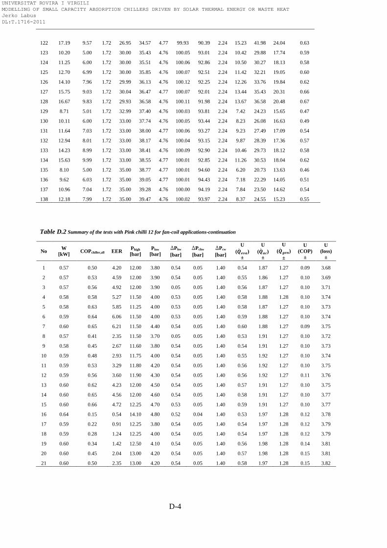
D-4
122 17.19 9.57 1.72 26.95 34.57 4.77 99.93 90.39 2.24 15.23 41.98 24.04 0.63
123 10.20 5.00 1.72 30.00 35.43 4.76 100.05 93.01 2.24 10.42 29.88 17.74 0.59
124 11.25 6.00 1.72 30.00 35.51 4.76 100.06 92.86 2.24 10.50 30.27 18.13 0.58
125 12.70 6.99 1.72 30.00 35.85 4.76 100.07 92.51 2.24 11.42 32.21 19.05 0.60
126 14.10 7.96 1.72 29.99 36.13 4.76 100.12 92.25 2.24 12.26 33.76 19.84 0.62
127 15.75 9.03 1.72 30.04 36.47 4.77 100.07 92.01 2.24 13.44 35.43 20.31 0.66
128 16.67 9.83 1.72 29.93 36.58 4.76 100.11 91.98 2.24 13.67 36.58 20.48 0.67
129 8.71 5.01 1.72 32.99 37.40 4.76 100.03 93.81 2.24 7.42 24.23 15.65 0.47
130 10.11 6.00 1.72 33.00 37.74 4.76 100.05 93.44 2.24 8.23 26.08 16.63 0.49
131 11.64 7.03 1.72 33.00 38.00 4.77 100.06 93.27 2.24 9.23 27.49 17.09 0.54
132 12.94 8.01 1.72 33.00 38.17 4.76 100.04 93.15 2.24 9.87 28.39 17.36 0.57
133 14.23 8.99 1.72 33.00 38.41 4.76 100.09 92.90 2.24 10.46 29.73 18.12 0.58
134 15.63 9.99 1.72 33.00 38.55 4.77 100.01 92.85 2.24 11.26 30.53 18.04 0.62
135 8.10 5.00 1.72 35.00 38.77 4.77 100.01 94.60 2.24 6.20 20.73 13.63 0.46
136 9.62 6.03 1.72 35.00 39.05 4.77 100.01 94.43 2.24 7.18 22.29 14.05 0.51
137 10.96 7.04 1.72 35.00 39.28 4.76 100.00 94.19 2.24 7.84 23.50 14.62 0.54
138 12.18 7.99 1.72 35.00 39.47 4.76 100.02 93.97 2.24 8.37 24.55 15.23 0.55
Table D.2 Summary of the tests with Pink chilli 12 for fan-coil applications-continuation
No W
[kW] COPchiller,all EER
Phigh
[bar]
Plow
[bar]
DPhw
[bar]
DPchw
[bar]
DPcw
[bar]
U
( )
±
U
( )
±
U
( )
±
U
(COP)
±
U
(loss)
±
1 0.57 0.50 4.20 12.00 3.80 0.54 0.05 1.40 0.54 1.87 1.27 0.09 3.68
2 0.57 0.53 4.59 12.00 3.90 0.54 0.05 1.40 0.55 1.86 1.27 0.10 3.69
3 0.57 0.56 4.92 12.00 3.90 0.05 0.05 1.40 0.56 1.87 1.27 0.10 3.71
4 0.58 0.58 5.27 11.50 4.00 0.53 0.05 1.40 0.58 1.88 1.28 0.10 3.74
5 0.58 0.63 5.85 11.25 4.00 0.53 0.05 1.40 0.58 1.87 1.27 0.10 3.73
6 0.59 0.64 6.06 11.50 4.00 0.53 0.05 1.40 0.59 1.88 1.27 0.10 3.74
7 0.60 0.65 6.21 11.50 4.40 0.54 0.05 1.40 0.60 1.88 1.27 0.09 3.75
8 0.57 0.41 2.35 11.50 3.70 0.05 0.05 1.40 0.53 1.91 1.27 0.10 3.72
9 0.58 0.45 2.67 11.60 3.80 0.54 0.05 1.40 0.54 1.91 1.27 0.10 3.73
10 0.59 0.48 2.93 11.75 4.00 0.54 0.05 1.40 0.55 1.92 1.27 0.10 3.74
11 0.59 0.53 3.29 11.80 4.20 0.54 0.05 1.40 0.56 1.92 1.27 0.10 3.75
12 0.59 0.56 3.60 11.90 4.30 0.54 0.05 1.40 0.56 1.92 1.27 0.11 3.76
13 0.60 0.62 4.23 12.00 4.50 0.54 0.05 1.40 0.57 1.91 1.27 0.10 3.75
14 0.60 0.65 4.56 12.00 4.60 0.54 0.05 1.40 0.58 1.91 1.27 0.10 3.77
15 0.60 0.66 4.72 12.25 4.70 0.53 0.05 1.40 0.59 1.91 1.27 0.10 3.77
16 0.64 0.15 0.54 14.10 4.80 0.52 0.04 1.40 0.53 1.97 1.28 0.12 3.78
17 0.59 0.22 0.91 12.25 3.80 0.54 0.05 1.40 0.54 1.97 1.28 0.12 3.79
18 0.59 0.28 1.24 12.25 4.00 0.54 0.05 1.40 0.54 1.97 1.28 0.12 3.79
19 0.60 0.34 1.42 12.50 4.10 0.54 0.05 1.40 0.56 1.98 1.28 0.14 3.81
20 0.60 0.45 2.04 13.00 4.20 0.54 0.05 1.40 0.57 1.98 1.28 0.15 3.81
21 0.60 0.50 2.35 13.00 4.20 0.54 0.05 1.40 0.58 1.97 1.28 0.15 3.82
UNIVERSITAT ROVIRA I VIRGILI MODELLING OF SMALL CAPACITY ABSORPTION CHILLERS DRIVEN BY SOLAR THERMAL ENERGY OR WASTE HEAT Jerko Labus DL:T.1716-2011
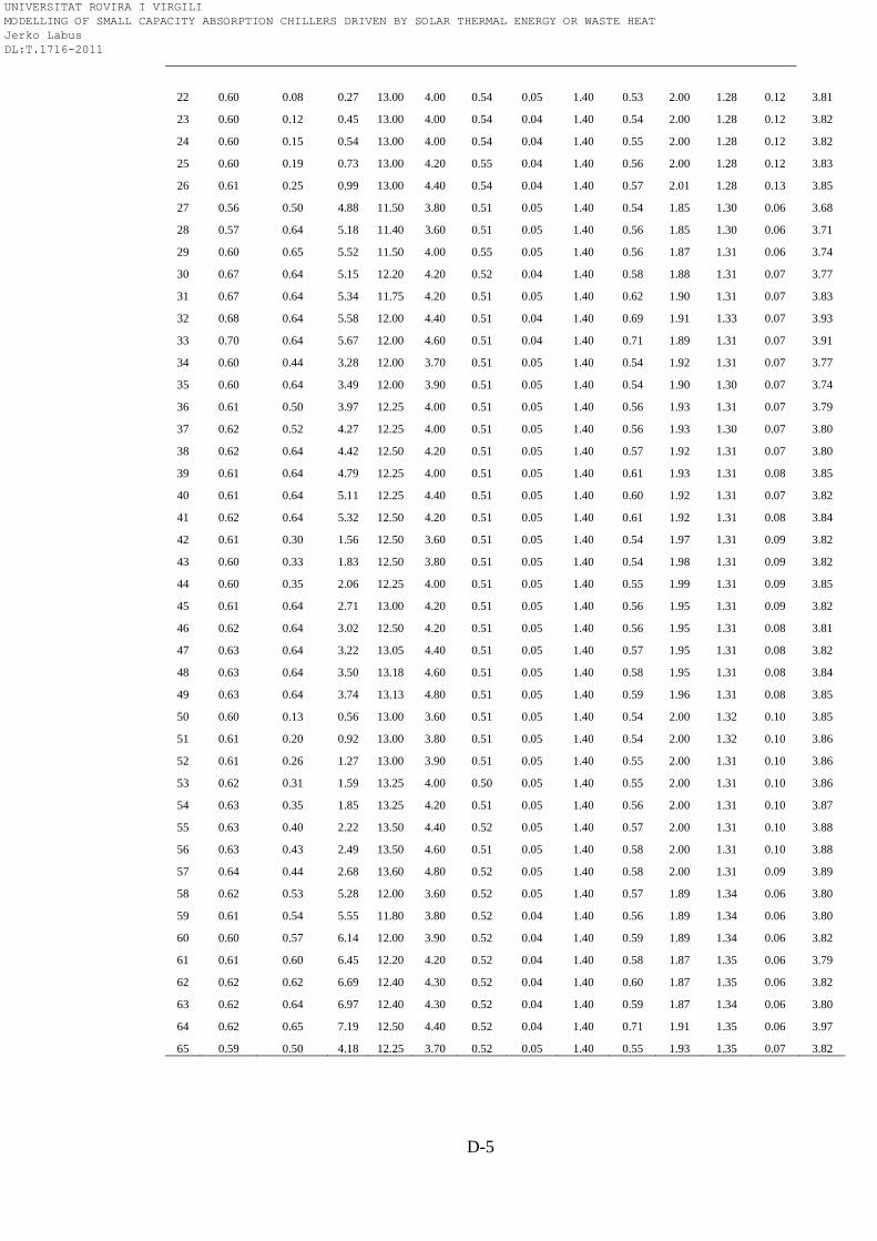
D-5
22 0.60 0.08 0.27 13.00 4.00 0.54 0.05 1.40 0.53 2.00 1.28 0.12 3.81
23 0.60 0.12 0.45 13.00 4.00 0.54 0.04 1.40 0.54 2.00 1.28 0.12 3.82
24 0.60 0.15 0.54 13.00 4.00 0.54 0.04 1.40 0.55 2.00 1.28 0.12 3.82
25 0.60 0.19 0.73 13.00 4.20 0.55 0.04 1.40 0.56 2.00 1.28 0.12 3.83
26 0.61 0.25 0.99 13.00 4.40 0.54 0.04 1.40 0.57 2.01 1.28 0.13 3.85
27 0.56 0.50 4.88 11.50 3.80 0.51 0.05 1.40 0.54 1.85 1.30 0.06 3.68
28 0.57 0.64 5.18 11.40 3.60 0.51 0.05 1.40 0.56 1.85 1.30 0.06 3.71
29 0.60 0.65 5.52 11.50 4.00 0.55 0.05 1.40 0.56 1.87 1.31 0.06 3.74
30 0.67 0.64 5.15 12.20 4.20 0.52 0.04 1.40 0.58 1.88 1.31 0.07 3.77
31 0.67 0.64 5.34 11.75 4.20 0.51 0.05 1.40 0.62 1.90 1.31 0.07 3.83
32 0.68 0.64 5.58 12.00 4.40 0.51 0.04 1.40 0.69 1.91 1.33 0.07 3.93
33 0.70 0.64 5.67 12.00 4.60 0.51 0.04 1.40 0.71 1.89 1.31 0.07 3.91
34 0.60 0.44 3.28 12.00 3.70 0.51 0.05 1.40 0.54 1.92 1.31 0.07 3.77
35 0.60 0.64 3.49 12.00 3.90 0.51 0.05 1.40 0.54 1.90 1.30 0.07 3.74
36 0.61 0.50 3.97 12.25 4.00 0.51 0.05 1.40 0.56 1.93 1.31 0.07 3.79
37 0.62 0.52 4.27 12.25 4.00 0.51 0.05 1.40 0.56 1.93 1.30 0.07 3.80
38 0.62 0.64 4.42 12.50 4.20 0.51 0.05 1.40 0.57 1.92 1.31 0.07 3.80
39 0.61 0.64 4.79 12.25 4.00 0.51 0.05 1.40 0.61 1.93 1.31 0.08 3.85
40 0.61 0.64 5.11 12.25 4.40 0.51 0.05 1.40 0.60 1.92 1.31 0.07 3.82
41 0.62 0.64 5.32 12.50 4.20 0.51 0.05 1.40 0.61 1.92 1.31 0.08 3.84
42 0.61 0.30 1.56 12.50 3.60 0.51 0.05 1.40 0.54 1.97 1.31 0.09 3.82
43 0.60 0.33 1.83 12.50 3.80 0.51 0.05 1.40 0.54 1.98 1.31 0.09 3.82
44 0.60 0.35 2.06 12.25 4.00 0.51 0.05 1.40 0.55 1.99 1.31 0.09 3.85
45 0.61 0.64 2.71 13.00 4.20 0.51 0.05 1.40 0.56 1.95 1.31 0.09 3.82
46 0.62 0.64 3.02 12.50 4.20 0.51 0.05 1.40 0.56 1.95 1.31 0.08 3.81
47 0.63 0.64 3.22 13.05 4.40 0.51 0.05 1.40 0.57 1.95 1.31 0.08 3.82
48 0.63 0.64 3.50 13.18 4.60 0.51 0.05 1.40 0.58 1.95 1.31 0.08 3.84
49 0.63 0.64 3.74 13.13 4.80 0.51 0.05 1.40 0.59 1.96 1.31 0.08 3.85
50 0.60 0.13 0.56 13.00 3.60 0.51 0.05 1.40 0.54 2.00 1.32 0.10 3.85
51 0.61 0.20 0.92 13.00 3.80 0.51 0.05 1.40 0.54 2.00 1.32 0.10 3.86
52 0.61 0.26 1.27 13.00 3.90 0.51 0.05 1.40 0.55 2.00 1.31 0.10 3.86
53 0.62 0.31 1.59 13.25 4.00 0.50 0.05 1.40 0.55 2.00 1.31 0.10 3.86
54 0.63 0.35 1.85 13.25 4.20 0.51 0.05 1.40 0.56 2.00 1.31 0.10 3.87
55 0.63 0.40 2.22 13.50 4.40 0.52 0.05 1.40 0.57 2.00 1.31 0.10 3.88
56 0.63 0.43 2.49 13.50 4.60 0.51 0.05 1.40 0.58 2.00 1.31 0.10 3.88
57 0.64 0.44 2.68 13.60 4.80 0.52 0.05 1.40 0.58 2.00 1.31 0.09 3.89
58 0.62 0.53 5.28 12.00 3.60 0.52 0.05 1.40 0.57 1.89 1.34 0.06 3.80
59 0.61 0.54 5.55 11.80 3.80 0.52 0.04 1.40 0.56 1.89 1.34 0.06 3.80
60 0.60 0.57 6.14 12.00 3.90 0.52 0.04 1.40 0.59 1.89 1.34 0.06 3.82
61 0.61 0.60 6.45 12.20 4.20 0.52 0.04 1.40 0.58 1.87 1.35 0.06 3.79
62 0.62 0.62 6.69 12.40 4.30 0.52 0.04 1.40 0.60 1.87 1.35 0.06 3.82
63 0.62 0.64 6.97 12.40 4.30 0.52 0.04 1.40 0.59 1.87 1.34 0.06 3.80
64 0.62 0.65 7.19 12.50 4.40 0.52 0.04 1.40 0.71 1.91 1.35 0.06 3.97
65 0.59 0.50 4.18 12.25 3.70 0.52 0.05 1.40 0.55 1.93 1.35 0.07 3.82
UNIVERSITAT ROVIRA I VIRGILI MODELLING OF SMALL CAPACITY ABSORPTION CHILLERS DRIVEN BY SOLAR THERMAL ENERGY OR WASTE HEAT Jerko Labus DL:T.1716-2011
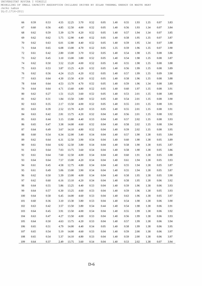
D-6
66 0.59 0.53 4.55 12.25 3.70 0.52 0.05 1.40 0.55 1.93 1.35 0.07 3.83
67 0.60 0.56 4.85 12.50 4.00 0.52 0.05 1.40 0.56 1.93 1.34 0.07 3.84
68 0.62 0.59 5.39 12.70 4.20 0.52 0.05 1.40 0.57 1.94 1.34 0.07 3.85
69 0.62 0.62 5.75 12.90 4.40 0.52 0.05 1.40 0.58 1.95 1.35 0.07 3.87
70 0.62 0.63 6.01 12.80 4.40 0.52 0.05 1.40 0.59 1.95 1.34 0.07 3.88
71 0.64 0.65 6.08 13.00 4.70 0.52 0.05 1.35 0.59 1.96 1.35 0.07 3.90
72 0.61 0.42 2.80 13.00 3.70 0.52 0.05 1.40 0.54 1.98 1.35 0.08 3.86
73 0.62 0.45 3.10 13.00 3.80 0.52 0.05 1.40 0.54 1.98 1.35 0.08 3.87
74 0.62 0.50 3.52 13.20 4.00 0.52 0.05 1.40 0.55 1.98 1.35 0.08 3.88
75 0.63 0.53 3.87 13.25 4.20 0.52 0.05 1.40 0.56 1.99 1.35 0.08 3.89
76 0.62 0.56 4.24 13.25 4.20 0.52 0.05 1.40 0.57 1.99 1.35 0.09 3.90
77 0.63 0.64 4.30 13.50 4.50 0.52 0.05 1.40 0.58 1.96 1.35 0.08 3.88
78 0.64 0.64 4.53 13.70 4.70 0.52 0.05 1.40 0.59 1.96 1.34 0.08 3.89
79 0.64 0.64 4.71 13.60 4.80 0.52 0.05 1.40 0.60 1.97 1.35 0.08 3.91
80 0.62 0.27 1.51 13.25 3.60 0.52 0.05 1.40 0.53 2.01 1.35 0.08 3.89
81 0.62 0.31 1.84 13.50 3.80 0.52 0.05 1.40 0.54 2.01 1.35 0.08 3.90
82 0.63 0.35 2.17 13.50 4.00 0.52 0.05 1.40 0.55 2.01 1.35 0.08 3.91
83 0.63 0.39 2.52 13.70 4.20 0.53 0.05 1.40 0.55 2.01 1.35 0.08 3.91
84 0.63 0.42 2.81 13.75 4.20 0.52 0.04 1.40 0.56 2.01 1.35 0.08 3.92
85 0.63 0.44 3.15 13.80 4.40 0.53 0.04 1.40 0.57 2.02 1.35 0.08 3.93
86 0.65 0.47 3.38 14.00 4.60 0.52 0.04 1.40 0.58 2.02 1.35 0.08 3.94
87 0.64 0.49 3.67 14.10 4.80 0.52 0.04 1.40 0.59 2.02 1.35 0.08 3.95
88 0.60 0.54 6.34 12.00 3.40 0.54 0.04 1.40 0.57 1.90 1.38 0.05 3.84
89 0.62 0.64 6.31 12.50 3.90 0.54 0.04 1.40 0.60 1.90 1.38 0.05 3.89
90 0.61 0.64 6.92 12.50 3.80 0.54 0.04 1.40 0.58 1.90 1.38 0.05 3.87
91 0.63 0.64 7.03 13.75 3.60 0.54 0.04 1.40 0.58 1.90 1.38 0.05 3.86
92 0.61 0.64 7.60 12.50 4.00 0.54 0.04 1.40 0.60 1.91 1.38 0.05 3.88
93 0.64 0.64 7.57 13.00 4.20 0.54 0.04 1.40 0.61 1.94 1.38 0.05 3.93
94 0.61 0.45 4.58 12.75 4.80 0.54 0.04 1.40 0.55 1.94 1.38 0.05 3.87
95 0.61 0.49 5.06 13.00 3.90 0.54 0.04 1.40 0.55 1.94 1.38 0.05 3.87
96 0.62 0.50 5.39 13.00 4.00 0.54 0.04 1.40 0.58 1.95 1.38 0.05 3.90
97 0.62 0.60 6.16 13.10 4.20 0.54 0.04 1.40 0.58 1.95 1.38 0.06 3.92
98 0.64 0.55 5.86 13.25 4.40 0.53 0.04 1.40 0.59 1.96 1.38 0.06 3.93
99 0.64 0.57 6.30 13.25 4.60 0.53 0.04 1.40 0.59 1.96 1.38 0.05 3.93
100 0.64 0.58 6.45 14.00 4.60 0.53 0.04 1.40 0.63 1.96 1.38 0.05 3.97
101 0.60 0.36 3.10 13.30 3.80 0.53 0.04 1.40 0.54 1.98 1.38 0.06 3.90
102 0.63 0.42 3.57 13.50 3.80 0.54 0.44 1.40 0.54 1.98 1.38 0.06 3.91
103 0.64 0.45 3.91 13.50 4.00 0.54 0.04 1.40 0.55 1.99 1.38 0.06 3.92
104 0.63 0.47 4.27 13.50 4.00 0.53 0.04 1.40 0.56 1.99 1.38 0.06 3.93
105 0.64 0.50 4.63 13.75 4.20 0.53 0.04 1.40 0.57 1.99 1.38 0.06 3.94
106 0.65 0.51 4.79 14.00 4.40 0.54 0.05 1.40 0.58 1.99 1.38 0.06 3.95
107 0.65 0.54 5.19 14.00 4.60 0.53 0.04 1.40 0.59 2.00 1.38 0.06 3.97
108 0.65 0.54 5.37 14.10 4.80 0.53 0.04 1.40 0.59 2.00 1.38 0.06 3.97
109 0.64 0.37 2.49 13.75 3.60 0.54 0.04 1.40 0.53 2.02 1.38 0.07 3.94
UNIVERSITAT ROVIRA I VIRGILI MODELLING OF SMALL CAPACITY ABSORPTION CHILLERS DRIVEN BY SOLAR THERMAL ENERGY OR WASTE HEAT Jerko Labus DL:T.1716-2011
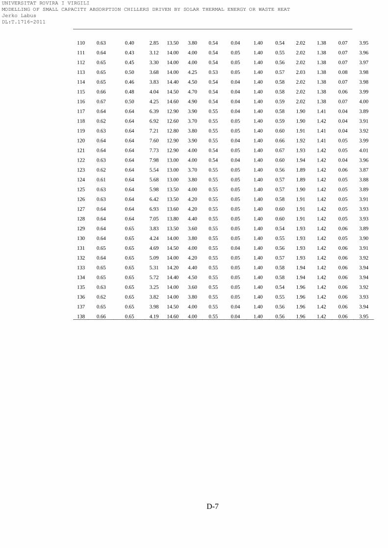
D-7
110 0.63 0.40 2.85 13.50 3.80 0.54 0.04 1.40 0.54 2.02 1.38 0.07 3.95
111 0.64 0.43 3.12 14.00 4.00 0.54 0.05 1.40 0.55 2.02 1.38 0.07 3.96
112 0.65 0.45 3.30 14.00 4.00 0.54 0.05 1.40 0.56 2.02 1.38 0.07 3.97
113 0.65 0.50 3.68 14.00 4.25 0.53 0.05 1.40 0.57 2.03 1.38 0.08 3.98
114 0.65 0.46 3.83 14.40 4.50 0.54 0.04 1.40 0.58 2.02 1.38 0.07 3.98
115 0.66 0.48 4.04 14.50 4.70 0.54 0.04 1.40 0.58 2.02 1.38 0.06 3.99
116 0.67 0.50 4.25 14.60 4.90 0.54 0.04 1.40 0.59 2.02 1.38 0.07 4.00
117 0.64 0.64 6.39 12.90 3.90 0.55 0.04 1.40 0.58 1.90 1.41 0.04 3.89
118 0.62 0.64 6.92 12.60 3.70 0.55 0.05 1.40 0.59 1.90 1.42 0.04 3.91
119 0.63 0.64 7.21 12.80 3.80 0.55 0.05 1.40 0.60 1.91 1.41 0.04 3.92
120 0.64 0.64 7.60 12.90 3.90 0.55 0.04 1.40 0.66 1.92 1.41 0.05 3.99
121 0.64 0.64 7.73 12.90 4.00 0.54 0.05 1.40 0.67 1.93 1.42 0.05 4.01
122 0.63 0.64 7.98 13.00 4.00 0.54 0.04 1.40 0.60 1.94 1.42 0.04 3.96
123 0.62 0.64 5.54 13.00 3.70 0.55 0.05 1.40 0.56 1.89 1.42 0.06 3.87
124 0.61 0.64 5.68 13.00 3.80 0.55 0.05 1.40 0.57 1.89 1.42 0.05 3.88
125 0.63 0.64 5.98 13.50 4.00 0.55 0.05 1.40 0.57 1.90 1.42 0.05 3.89
126 0.63 0.64 6.42 13.50 4.20 0.55 0.05 1.40 0.58 1.91 1.42 0.05 3.91
127 0.64 0.64 6.93 13.60 4.20 0.55 0.05 1.40 0.60 1.91 1.42 0.05 3.93
128 0.64 0.64 7.05 13.80 4.40 0.55 0.05 1.40 0.60 1.91 1.42 0.05 3.93
129 0.64 0.65 3.83 13.50 3.60 0.55 0.05 1.40 0.54 1.93 1.42 0.06 3.89
130 0.64 0.65 4.24 14.00 3.80 0.55 0.05 1.40 0.55 1.93 1.42 0.05 3.90
131 0.65 0.65 4.69 14.50 4.00 0.55 0.04 1.40 0.56 1.93 1.42 0.06 3.91
132 0.64 0.65 5.09 14.00 4.20 0.55 0.05 1.40 0.57 1.93 1.42 0.06 3.92
133 0.65 0.65 5.31 14.20 4.40 0.55 0.05 1.40 0.58 1.94 1.42 0.06 3.94
134 0.65 0.65 5.72 14.40 4.50 0.55 0.05 1.40 0.58 1.94 1.42 0.06 3.94
135 0.63 0.65 3.25 14.00 3.60 0.55 0.05 1.40 0.54 1.96 1.42 0.06 3.92
136 0.62 0.65 3.82 14.00 3.80 0.55 0.05 1.40 0.55 1.96 1.42 0.06 3.93
137 0.65 0.65 3.98 14.50 4.00 0.55 0.04 1.40 0.56 1.96 1.42 0.06 3.94
138 0.66 0.65 4.19 14.60 4.00 0.55 0.04 1.40 0.56 1.96 1.42 0.06 3.95
UNIVERSITAT ROVIRA I VIRGILI MODELLING OF SMALL CAPACITY ABSORPTION CHILLERS DRIVEN BY SOLAR THERMAL ENERGY OR WASTE HEAT Jerko Labus DL:T.1716-2011