midnite solar classic - yahoolib.store.yahoo.net/lib/wind-sun/classic-manual.pdf · midnite solar...
TRANSCRIPT

MidNite Solar Classic Owner’s Manual 1/7/13
Standard Classic Classic Lite
This Manual covers models Classic 150, 200, 250 & 250KS
as well as the Classic 150, 200, 250 & 250KS LITE
Este manual también está disponible en Español. La versión en Español puede encontrarse en nuestra
pagina web en la ficha Documentos y haga clic en Manuales.
Classic owner’s manual (continued)
2 | P a g e 1 0 - 0 0 1 - 1 R E V : C
The MidNite Solar Classic charge controller conforms to UL 1741, Safety for Inverters, Converters, Controllers
and Interconnection System Equipment for Use With Distributed Energy Resources, Second Edition, May 7,
1999 with revisions through January 28, 2010 and
CAN/CSA C22.2 No. 107.1: 2001/09/01 Ed: 3 (R2006)
Notice of Copyright
MidNite Solar's Classic charge controller User’s Manual
Copyright ⓒ 2010 all rights reserved.
MidNite Solar Inc. reserves the right to revise this document and to periodically make changes to the content hereof
without obligation or organization of such revisions or changes unless required to do so by prior arrangement.
Disclaimer
Unless specifically agreed to in writing, MidNite Solar Inc.
(a) Makes no warranty as to the accuracy, sufficiency or suitability of any technical or other information provided in
its manuals or other documentation.
(b) Assumes no responsibility or liability for loss or damage whether direct, indirect, consequential or incidental,
which might arise out of use of such information. The use of any such information will be entirely at the user's risk.
Contact Information
Telephone: 360.403.7207
Fax: 360.691.6862
Email: [email protected]
Web: www.midnitesolar.com
Classic owner’s manual (continued)
3 | P a g e 1 0 - 0 0 1 - 1 R E V : C
Contents Scope ............................................................................................................................................................................. 8
Introduction ................................................................................................................................................................. 8
Classic Power Curves ................................................................................................................................................ 10
Unpacking the Classic ............................................................................................................................................... 12
Removing and installing the front cover on the Classic ........................................................................................ 13
Mounting the Classic ................................................................................................................................................ 14
Alternative Mounting .............................................................................................................................................. 15
Dimensions .......................................................................................................................................................... 15
Sealed or Vented ..................................................................................................................................................... 16
Battery Temperature Compensation ....................................................................................................................... 16
“Follow-ME” Charging coordination ..................................................................................................................... 17
Battery Temperature Sensor Installation ............................................................................................................... 19
Chassis Grounding .................................................................................................................................................... 21
DC System Grounding ............................................................................................................................................ 21
DC GFP (Ground Fault Protection) ........................................................................................................................ 22
Disabling GFP ......................................................................................................................................................... 22
Wiring the Classic ..................................................................................................................................................... 23
DC Terminal Connector .......................................................................................................................................... 26
Over Current Protection and Wire Size Requirements ........................................................................................ 26
Current Rating ......................................................................................................................................................... 27
Over Current Protection .......................................................................................................................................... 27
Long Distance Wire Runs ....................................................................................................................................... 27
Connecting the Classic to the Clipper ..................................................................................................................... 27
Maximum and Minimum Wire Size ....................................................................................................................... 29
Equalization Manual and Auto ................................................................................................................................ 29
Equalization with the Classic Lite........................................................................................................................... 29
Equalization with the standard Classic ................................................................................................................... 30
Manual EQ ........................................................................................................................................................... 30
Auto EQ ............................................................................................................................................................... 30
Standard Classic programming ............................................................................................................................... 31
Commissioning the Classic (Quick Start) ............................................................................................................... 31
Battery Charge Stages and Meanings ..................................................................................................................... 31
Resting ................................................................................................................................................................ 31
Mode is OFF ....................................................................................................................................................... 32
Classic owner’s manual (continued)
4 | P a g e 1 0 - 0 0 1 - 1 R E V : C
Adjusting Absorb, Equalize and Float Voltages ..................................................................................................... 32
Current Limit........................................................................................................................................................... 32
LED Modes and the “Blinking Red LED” .............................................................................................................. 33
Calibrating Battery and PV Voltage ....................................................................................................................... 33
Configuring DC Input Source ................................................................................................................................. 34
Configuring the Classic for Wind Input Source ...................................................................................................... 35
Setting the Date and Time ....................................................................................................................................... 36
Setting Longitude and Latitude ............................................................................................................................... 36
Configuring Auxiliary Input/Output ....................................................................................................................... 36
Aux 1 Function .................................................................................................................................................... 41
Aux 2 Function. Output/Input ............................................................................................................................. 41
Aux 1 and Aux 2 Graphs/Jumpers .......................................................................................................................... 42
Aux 1 Voltage-Time Relation (Relay/12v) ............................................................................................................. 43
Aux 2 Voltage-Time Relation (PWM) .................................................................................................................... 44
Setting the MNGP features ..................................................................................................................................... 44
Navigating the Menu's ............................................................................................................................................ 45
Viewing Other MidNite Products on the Display ................................................................................................... 45
Connecting Classic to Two MNGPs/Network cable ............................................................................................... 46
Arc Fault ................................................................................................................................................................. 46
View Faults and Warning's ..................................................................................................................................... 47
View Logged Data .................................................................................................................................................. 48
Graphical Logging Display modes .......................................................................................................................... 50
Dealer Information Screen ...................................................................................................................................... 52
Classic Lite Programming ........................................................................................................................................ 53
LED explanations .................................................................................................................................................... 53
Programming ........................................................................................................................................................... 54
Dip Switches ........................................................................................................................................................... 54
Section 1 Switch settings explained ................................................................................................................. 56
Section 2 Switch settings explained ................................................................................................................. 57
Battery voltage and time settings ........................................................................................................................ 60
Using MNGP Remote to program a Classic Lite .................................................................................................... 61
Programming the Lite with a Networked Standard Classic .................................................................................... 61
Programming the Lite with the Local App.............................................................................................................. 61
Clearing Faults ........................................................................................................................................................ 61
Notes on the Lite ..................................................................................................................................................... 61
Classic owner’s manual (continued)
5 | P a g e 1 0 - 0 0 1 - 1 R E V : C
Explanations of Solar and Legacy........................................................................................................................... 62
Uploading New Firmware to the Classic ................................................................................................................. 62
Connecting the Classic to the Internet .................................................................................................................... 65
Networking.............................................................................................................................................................. 65
Network Setup Through the MNGP ....................................................................................................................... 67
Web Access ............................................................................................................................................................. 69
Local Network ......................................................................................................................................................... 69
Positive Ground systems ........................................................................................................................................... 69
Troubleshooting ........................................................................................................................................................ 71
Specifications Electrical ............................................................................................................................................ 72
Specifications Mechanical ........................................................................................................................................ 73
Default Battery charge set points ............................................................................................................................. 74
Optional accessories .................................................................................................................................................. 74
Regulatory Approval ................................................................................................................................................ 74
Warranty.................................................................................................................................................................... 75
Appendix .................................................................................................................................................................... 75
Classic Breaker sizing ............................................................................................................................................. 76
................................................................................................................................................................................. 77
Label Set from Classic ............................................................................................................................................ 78
RS232 Jack Pin Out ................................................................................................................................................ 79
Classic owner’s manual (continued)
6 | P a g e 1 0 - 0 0 1 - 1 R E V : C
Absorb – Constant voltage charge stage to fill the batteries. The controller is regulating so maximum power will not
be seen at this time. The Absorb timer is also counting down to the switch to Float.
A-EQ-R – This will reload the Auto Equalize counters, basically it will start the counters from day 1.
AF – Arc Fault, See page 46 for more info on arc fault protection.
Arc Adjust – This menu is where you adjust the Arc Fault sensitivity. For info on Arc Fault see page 46.
A-RST – Auto reset of the Classic controller, The Classic will reboot around Midnight every night when this is
enabled. This is useful for very remote sites where a loss of internet capability for example would be a hard ship.
Aux – Auxiliary relays. The Classic has 2 relays: Aux 1 can be configured as a 12 volt signal or a dry relay, Aux 2
can be used as a PWM signal output. Refer to page 36 for more Aux info.
BLK – Bulk MPPT Mode. By using the up arrow in Tweaks under BLK you can force the Classic into Bulk mode.
Bulk MPPT - Maximum current charge stage, the Classic is trying to bring the batteries to the Absorb voltage set
point. We are basically putting all available power into the batteries.
Comm – This Menu allows adjustment of things like Mod Bus port, USB Mode and MNGP address.
DvrtCnt – When enabled, allows the charge stage timers to continue to run when the diversion modes are holding
the battery voltage just below the actual set point.
Equalize - Constant voltage charge stage to equalize the batteries. The controller is regulating so maximum power
will not be seen at this time. The Equalize timer is also counting down to the switch to Float.
EQ MPPT - Maximum current charge stage, the Classic is trying to bring the batteries to the Equalize voltage set
point. We are basically putting all available power into the batteries.
Float – Constant voltage charge stage with a lower voltage than the Absorb charge point. The controller is
regulating so maximum power will not be seen at this time.
Float MPPT – Maximum current charge stage, the Classic is trying to bring the batteries to the Float voltage set
point. We are basically putting all available power into the batteries.
FLT – Float mode. By using the up arrow in Tweaks under FLT you can force the Classic into Float mode.
GF – Ground Fault, See page 22 for more info on ground fault protection.
Got Comm – Indicates a lack of communication between the display and the Classic. Consult Troubleshooting for
information page 71.
Insomnia – This when enabled, will keep the Classic from going to Resting. This is intended for hydro mode only
where you may need time to open water valves and do not want to wait for the Classic to wake up.
LED-MODE – This selection lets you pick the function of the 6 visible LED’s on a standard Classic.
Classic owner’s manual (continued)
7 | P a g e 1 0 - 0 0 1 - 1 R E V : C
LMX – LoMax, This enables the Classic to track the input voltage all the way down to Battery voltage. When
disabled the Classic will stop tracking the input around 5 volts above the battery voltage. When the input voltage is
within a couple volts of the battery voltage the inductors can “Sing” this is usually not very loud and will do no
harm.
Local App – Monitoring software included with the Classic for monitoring over the Local Network or Internet.
MNGP – Midnite Graphical interface Panel. This is the graphical display included with the standard Classic
controller.
MNLP – MidNite LED interface Panel. This is the LED display that comes standard with the Classic Lite.
Mode – This menu lets you turn the charging ability of the controller On / Off as well as lets you select the DC
input source. See page 31 for info on the Mode menu.
Mod Bus – a standard protocol used for communications. We have published our protocol to allow users to
interface with the Classic. See page Error! Bookmark not defined. for our Mod Bus protocol.
My MidNite – Web based monitoring for the Classic. (Not available yet)
NiteLog – When enabled allows the Classic to log data in the evening when the Classic is Resting.
PV Shading – This indicates the Maximum power point voltage is less than half the open circuit voltage.
Pwr Save – Allows you to adjust the time the Backlight stays on.
Resting – The Classic is not charging the battery due to low light. For reasons Resting will appear please see page
31.
Shade – When enabled the Classic will show PV Shading on the display when the Maximum power point voltage is
less than half the open circuit voltage.
T-Comp – Temperature compensation using a temperature sensor to measure the ambient temperature of the
battery bank and will adjust the voltage set points up or down accordingly to ensure a full battery. There are 3
parameters to set Minimum and Maximum adjusted voltage as well as volts per degree C per Cell. Typically this is -
.05 mV but please consult your battery manufacturer. See page 16 for Temperature compensation info.
Tweaks – This menu has all the advanced adjustments for the Classic. For example: Voltage off set adjustments etc.
VBatt – Battery voltage, measured at the battery terminals of the Classic.
VOC – Open Circuit Voltage, unloaded voltage measurement.
Vpv – Input voltage, measured at the input terminals of the Classic.
Web Access – When enabled allows the Classic to send data over the internet to My MidNite’s Server for you to
view when wanted.
Classic owner’s manual (continued)
8 | P a g e 1 0 - 0 0 1 - 1 R E V : C
Scope
This Manual provides safety guidelines and installation information for the Classic charge controller. It does not
provide brand specific information about photovoltaic panels, batteries etc. Contact the manufacturer of other
components in the system for relevant technical data.
Introduction
The MidNite Classic charge controller is unique in its ability to be used for a great variety of DC input sources. The
Classic is designed to regulate DC input from PV, and Approved Hydro and Wind turbines for other DC sources
please contact MidNite Solar tech support.. The Classic 150, 200 and 250 are designed to work with 12, 24, 36, 48,
60 and 72 volt battery banks.
The Classic250KS is designed to charge up to a 120V nominal battery bank.
The Classic can be installed stand alone or as a multi-unit networked installation.
Standard features of the Classic charge controller include:
*3 input operating voltage ranges 150, 200 and 250 VDC
*Multiple DC input options (example Solar, Wind or Hydro)
*Wizard driven setup interface including voice and help screens
*Graphical display
*Previous 180 days of operational data logged
*Internet ready
This Manual covers Classic 150, Classic 200 Classic 250 and the Classic 250KS. It covers the installation, wiring
and use of the Classic charge controller.
WARNING Warnings signs identify conditions or practices that could result in personal injury or loss of
life.
CAUTION Cautions identify conditions or practices that could result in damage to the unit or other
equipment.
MIDNITE SOLAR CHARGE CONTROLLER INSTALLATION GUIDELINES AND SAFETY
INSTRUCTIONS
This product is intended to be installed as part of a permanently grounded electrical system as shown in the system
configuration sections. The following important restrictions apply unless superseded by local or national codes:
•The System's DC Negative conductor must not be bonded to earth ground. The Classic does this with its internal
Ground Fault Protection circuitry. The battery negative and ground are not bonded together directly but are
connected together by the Classic’s internal GFP device. All negative conductor connections must be kept separate
from the grounding conductor connections. The equipment ground terminal inside the Classic must be connected to
Earth Ground for the internal DC-GFP to work. Continue
Classic owner’s manual (continued)
9 | P a g e 1 0 - 0 0 1 - 1 R E V : C
• With the exception of certain telecom applications, the Charge Controller should never be positive grounded.
• The Charge Controller equipment ground is marked with this symbol: • If damaged or malfunctioning, the Charge Controller should only be disassembled and repaired by a qualified
service center. Please contact your renewable energy dealer/installer for assistance. Incorrect reassembly risks
malfunction, electric shock or fire.
• The Charge Controller is designed for indoor installation or installation inside a weatherproof enclosure. It must
not be exposed to rain and should be installed out of direct sunlight.
For routine, user-approved maintenance:
• Turn off all circuit breakers, including those to the solar modules, batteries and related electrical connections
before performing any maintenance.
Standards and Requirements
All installations must comply with national and local electrical codes; professional installation is recommended. The
NEC in the USA requires a DC ground fault interrupter for all residential PV installations. NEC2011 requires an
ARC FAULT detector on all charge controllers and inverters operating above 80VDC. Both of these devices are
built into the Classic.
DC and Battery-Related Installation Requirements:
All DC cables must meet local and national codes.
Shut off all DC breakers before connecting any wiring.
Torque all the Charge Controller’s wire lugs and ground terminals to the specs found on page 19. Copper wiring must be rated at 75° C or higher.
Keep cables close together (e.g., using a tie-wrap) as much as possible to reduce inductance.
Ensure both cables pass through the same knockout and conduit to allow the inductive currents to cancel.
DC battery over-current protection must be used as part of the installation on the input and output.
Breakers between the battery and the Classic must meet UL489 standards.
Breakers between the DC source and the Classic must meet UL1077 or UL489 standards.
Design the battery enclosure to prevent accumulation of hydrogen gas at the top of the enclosure. Vent the battery
compartment from the highest point to the outside. A sloped lid can also be used to direct the flow of hydrogen to
the vent opening. Sealed (AGM, Gel etc) batteries do not normally require ventilation. Consult your battery
manufacturer for details.
WARNING: PERSONAL PRECAUTIONS DURING INSTALLATION
WARNING BATTERIES PRESENT RISK OF
ELECTRICAL SHOCK, BURN FROM HIGH SHORT CIRCUIT CURRENT, FIRE OR
EXPLOSION FROM VENTED GASES. FOLLOW PROPER PRECAUTIONS.
Someone should be within range of your voice to come to your aid if needed.
Keep plenty of fresh water and soap nearby in case battery acid contacts skin, clothing, or eyes.
Classic owner’s manual (continued)
10 | P a g e 1 0 - 0 0 1 - 1 R E V : C
Wear complete eye protection. Avoid touching eyes while working near batteries. Wash your hands with
soap and warm water when done.
If battery acid contacts skin or clothing, wash immediately with soap and water. If acid enters an eye, flood
the eye with running cool water at once for at least 15 minutes and get medical attention immediately
following.
Baking soda neutralizes lead acid battery electrolyte. Keep a supply on hand in the area of the batteries.
NEVER smoke or allow a spark or flame in vicinity of a battery or generator.
Be cautious to reduce the risk of dropping a metal tool onto batteries. It could short the batteries or other
electrical parts that can result in fire or explosion.
Never wear metal items such as rings, bracelets, necklaces, and watches when working with a battery or
other electrical circuits. A battery can produce a short circuit current high enough to weld a ring or the like
to metal, causing severe burns.
Classic Power Curves
Table 1
Table 2
Classic owner’s manual (continued)
11 | P a g e 1 0 - 0 0 1 - 1 R E V : C
Table 3
Table 4
The graphs above represent the max power output for a given input for each Classic. Using and understanding these
power graphs will help maximize Classic’s output power and aid in selecting wire and breaker/disconnects. The
built in set up wizard also helps select breakers and wire sizes. Notice that lower battery voltages and lower PV
input voltages result in higher continuous output power. The PV voltages listed are for reference and are not
intended to be the only PV voltages supported. The battery voltages listed show the most used battery bank
configurations. Other voltages are also supported. The Classic battery voltage parameters are fully user adjustable.
For example: if you are using a Classic 250 and 48v battery bank, the maximum continuous output power based
on 25 degree C ambient is 55 amps when using a PV array that yields a Maximum Power Voltage of 180 volts. The
same set up using a bit higher voltage modules that result in a 200V Maximum Power voltage will result in only 53
amps. Although 55 to 53 amps is not a significant change, it does give you the idea that all things being equal, lower
voltages are a bit more efficient.
Classic owner’s manual (continued)
12 | P a g e 1 0 - 0 0 1 - 1 R E V : C
Unpacking the Classic
When you receive your Classic you will want to unpack it and make sure everything is there and in good
shape. Refer to Figure 1.1. Included in the Classic package should be:
*Classic charge controller
*Battery temperature sensor
*Knock out covers 4 screened
*User’s manual DVD, printed installation instructions
*USB cable for upgrading Firmware
**Snap on upper vent cover
**Knock out covers 4 solid
**Note. These items are optional and do not ship as standard equipment. Email
[email protected] for more information or if anything is missing or damaged.
Figure 1
Classic owner’s manual (continued)
13 | P a g e 1 0 - 0 0 1 - 1 R E V : C
Removing and installing the front cover on the Classic
Removing the front art deco cover is required to gain access to the wiring compartment.
Be aware if this is not the first removal of this cover there is a cable connecting the cover to the electronics.
Do not pull hard or fast as damage could occur.
To remove the front cover of the Classic in preparation for installation, remove the 4 Phillips head screws with a #2
Phillips screwdriver. Lift the front half of the Classic casting off. You will need to unplug the display cable. It works
the same as any phone cable.
To re-install the front cover of the Classic you will need to plug in the display cable and carefully route it around the
components on the circuit board as you set the cover in place. See Figure 1.2 Do not force the cover if it does not
seat into place easily stop and look for any cables or wires that may be interfering. With the cover seated in place
install the four Phillips screws with a #2 Phillips screwdriver.
Figure 2
Classic owner’s manual (continued)
14 | P a g e 1 0 - 0 0 1 - 1 R E V : C
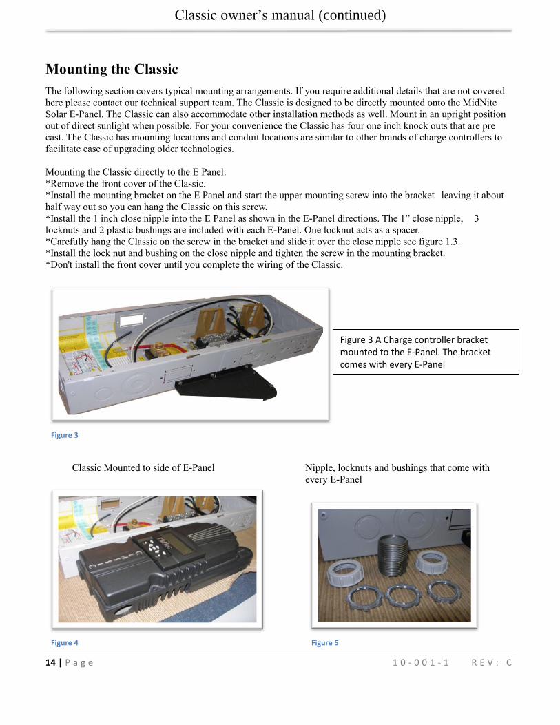
Mounting the Classic
The following section covers typical mounting arrangements. If you require additional details that are not covered
here please contact our technical support team. The Classic is designed to be directly mounted onto the MidNite
Solar E-Panel. The Classic can also accommodate other installation methods as well. Mount in an upright position
out of direct sunlight when possible. For your convenience the Classic has four one inch knock outs that are pre
cast. The Classic has mounting locations and conduit locations are similar to other brands of charge controllers to
facilitate ease of upgrading older technologies.
Mounting the Classic directly to the E Panel:
*Remove the front cover of the Classic.
*Install the mounting bracket on the E Panel and start the upper mounting screw into the bracket leaving it about
half way out so you can hang the Classic on this screw.
*Install the 1 inch close nipple into the E Panel as shown in the E-Panel directions. The 1” close nipple, 3
locknuts and 2 plastic bushings are included with each E-Panel. One locknut acts as a spacer.
*Carefully hang the Classic on the screw in the bracket and slide it over the close nipple see figure 1.3.
*Install the lock nut and bushing on the close nipple and tighten the screw in the mounting bracket.
*Don't install the front cover until you complete the wiring of the Classic.
Figure 3
Classic Mounted to side of E-Panel Nipple, locknuts and bushings that come with
every E-Panel
Figure 4 Figure 5
Figure 3 A Charge controller bracket mounted to the E-Panel. The bracket comes with every E-Panel
Classic owner’s manual (continued)
15 | P a g e 1 0 - 0 0 1 - 1 R E V : C
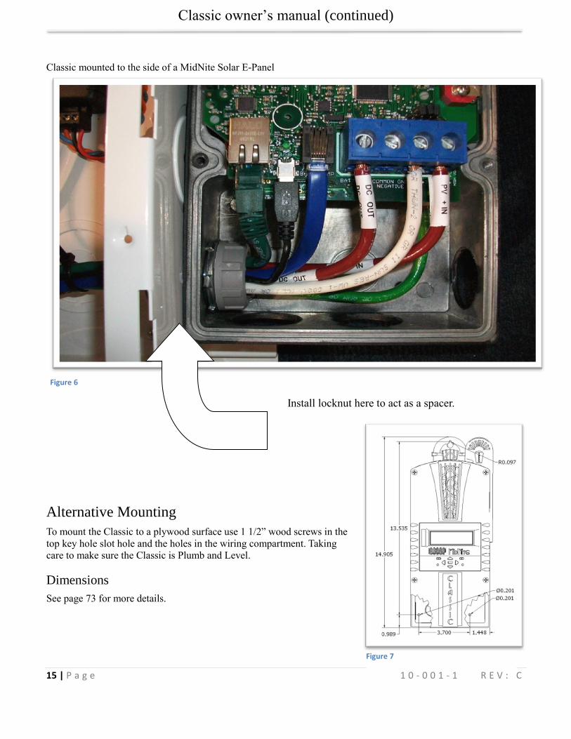
Classic mounted to the side of a MidNite Solar E-Panel
Figure 6
Install locknut here to act as a spacer.
Alternative Mounting
To mount the Classic to a plywood surface use 1 1/2” wood screws in the
top key hole slot hole and the holes in the wiring compartment. Taking
care to make sure the Classic is Plumb and Level.
Dimensions
See page 73 for more details.
Figure 7
Classic owner’s manual (continued)
16 | P a g e 1 0 - 0 0 1 - 1 R E V : C
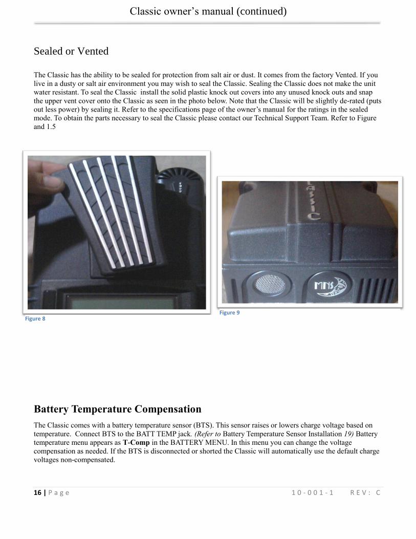
Sealed or Vented
The Classic has the ability to be sealed for protection from salt air or dust. It comes from the factory Vented. If you
live in a dusty or salt air environment you may wish to seal the Classic. Sealing the Classic does not make the unit
water resistant. To seal the Classic install the solid plastic knock out covers into any unused knock outs and snap
the upper vent cover onto the Classic as seen in the photo below. Note that the Classic will be slightly de-rated (puts
out less power) by sealing it. Refer to the specifications page of the owner’s manual for the ratings in the sealed
mode. To obtain the parts necessary to seal the Classic please contact our Technical Support Team. Refer to Figure
and 1.5
Battery Temperature Compensation
The Classic comes with a battery temperature sensor (BTS). This sensor raises or lowers charge voltage based on
temperature. Connect BTS to the BATT TEMP jack. (Refer to Battery Temperature Sensor Installation 19) Battery
temperature menu appears as T-Comp in the BATTERY MENU. In this menu you can change the voltage
compensation as needed. If the BTS is disconnected or shorted the Classic will automatically use the default charge
voltages non-compensated.
Figure 8 Figure 9
Classic owner’s manual (continued)
17 | P a g e 1 0 - 0 0 1 - 1 R E V : C
“Follow-ME” Charging coordination
Follow-Me will allow the Classics to share charge stages as well as Battery temperature info and Ground fault
coordination. Follow-Me also allows you to program a single Classic for Equalize charging and it will instruct all
the others to Equalize as well. You do need to set the Equalize parameters in each classic. For the Battery Temp
sensor you will need one BTS only and it can be on any of the Classics.
The Follow Me function basically is just what it is called. The Classic will simply ask the Classic to its right “What
do I do now” and this propagates around the loop continually. Whoever goes to Float first for instance will simply
tell everyone else it is time to go to float.
To enable Follow Me you need to wire the classics network cables as shown below. You also need to enable
Follow-ME. To do this, go to the Tweaks Menu. To do this press the “Main Menu” button repeatedly until
“Charge” is highlighted. Scroll to the Right until “Tweaks” is highlighted and press “Enter”. Now press the right
soft key (Upper right button) 4 times until you see the screen with “Follow-ME” and “BTSNET” on it. Here you
need to highlight Follow-ME and turn it on using the up arrow. You will also need to highlight BTSNET and turn it
on if you want to share battery temperature data. After enabling these press Enter to save this data.
Ground Fault sharing.
To share Ground fault you need to install the GFP Jumper on one classic only. You then need to make sure Ground
Fault is Enabled in the tweaks menu for any of the networked Classics you want to shut down on detection of
ground fault. For example say you have 3 solar Classics and one Wind Classic and you do not want the wind
Classic to shut down for GFP make sure in the tweaks menu of that Classic GFP is Disabled.
Naming the Classic
The included Local Application software allows you to issue a name to the Classic with upper and lower case
letters, as well as numbers. This name can be up to 8 characters. This name will show up on the Display of the
Classic instead of the word CLASSIC. It will be shown in all upper case on the Classics display. The Naming
process can be helpful for networked Classics that use one MNGP (Display) to view multiple Classics.
Addressing the Classic’s
You can assign unique addresses to each networked Classic. This is not necessary for Follow Me to work but it is
necessary if you want to view multiple Classics from a single MNGP. To address a Classic simply use the MNGP that
is plugged into that Classic, or plug the MNGP into that classic and hold the Left arrow button down and tap the up
or down button. The normal default address is 10 so going up will take you to 11 and down to 9. When you get to
the unused address you want for that Classic hold the left and right arrows for a second until Data sent and saved
shows up. Now this Classic has been re addressed to the new address. Do this for all the Classics or Classic lites on
the network.
Classic owner’s manual (continued)
18 | P a g e 1 0 - 0 0 1 - 1 R E V : C
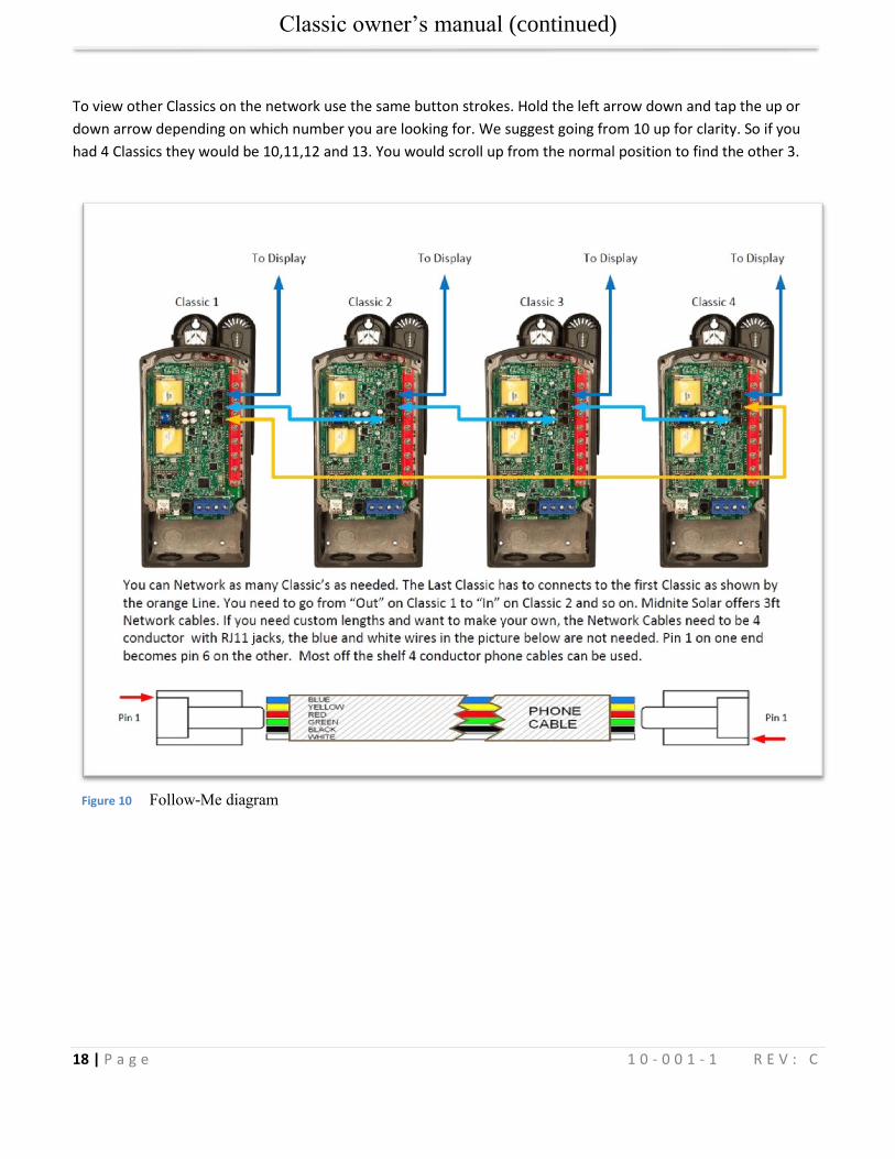
To view other Classics on the network use the same button strokes. Hold the left arrow down and tap the up or
down arrow depending on which number you are looking for. We suggest going from 10 up for clarity. So if you
had 4 Classics they would be 10,11,12 and 13. You would scroll up from the normal position to find the other 3.
Figure 10 Follow-Me diagram
Classic owner’s manual (continued)
19 | P a g e 1 0 - 0 0 1 - 1 R E V : C
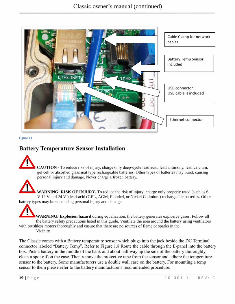
Figure 11
Battery Temperature Sensor Installation
CAUTION - To reduce risk of injury, charge only deep-cycle lead acid, lead antimony, lead calcium,
gel cell or absorbed glass mat type rechargeable batteries. Other types of batteries may burst, causing
personal injury and damage. Never charge a frozen battery.
WARNING: RISK OF INJURY. To reduce the risk of injury, charge only properly rated (such as 6
V 12 V and 24 V ) lead-acid (GEL, AGM, Flooded, or Nickel Cadmium) rechargeable batteries. Other
battery types may burst, causing personal injury and damage.
WARNING: Explosion hazard during equalization, the battery generates explosive gases. Follow all
the battery safety precautions listed in this guide. Ventilate the area around the battery using ventilators
with brushless motors thoroughly and ensure that there are no sources of flame or sparks in the
Vicinity.
The Classic comes with a Battery temperature sensor which plugs into the jack beside the DC Terminal
connector labeled “Battery Temp”. Refer to Figure 1.8 Route the cable through the E-panel into the battery
box. Pick a battery in the middle of the bank and about half way up the side of the battery thoroughly
clean a spot off on the case. Then remove the protective tape from the sensor and adhere the temperature
sensor to the battery. Some manufacturers use a double wall case on the battery. For mounting a temp
sensor to them please refer to the battery manufacturer's recommended procedure.
Battery Temp Sensor included
Cable Clamp for network cables
USB connector USB cable is included
Ethernet connector
Classic owner’s manual (continued)
20 | P a g e 1 0 - 0 0 1 - 1 R E V : C
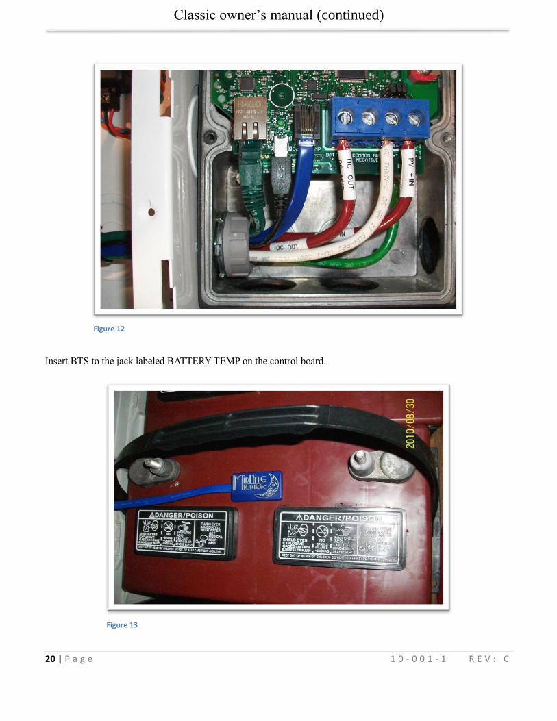
Figure 12
Insert BTS to the jack labeled BATTERY TEMP on the control board.
Figure 13
Classic owner’s manual (continued)
21 | P a g e 1 0 - 0 0 1 - 1 R E V : C
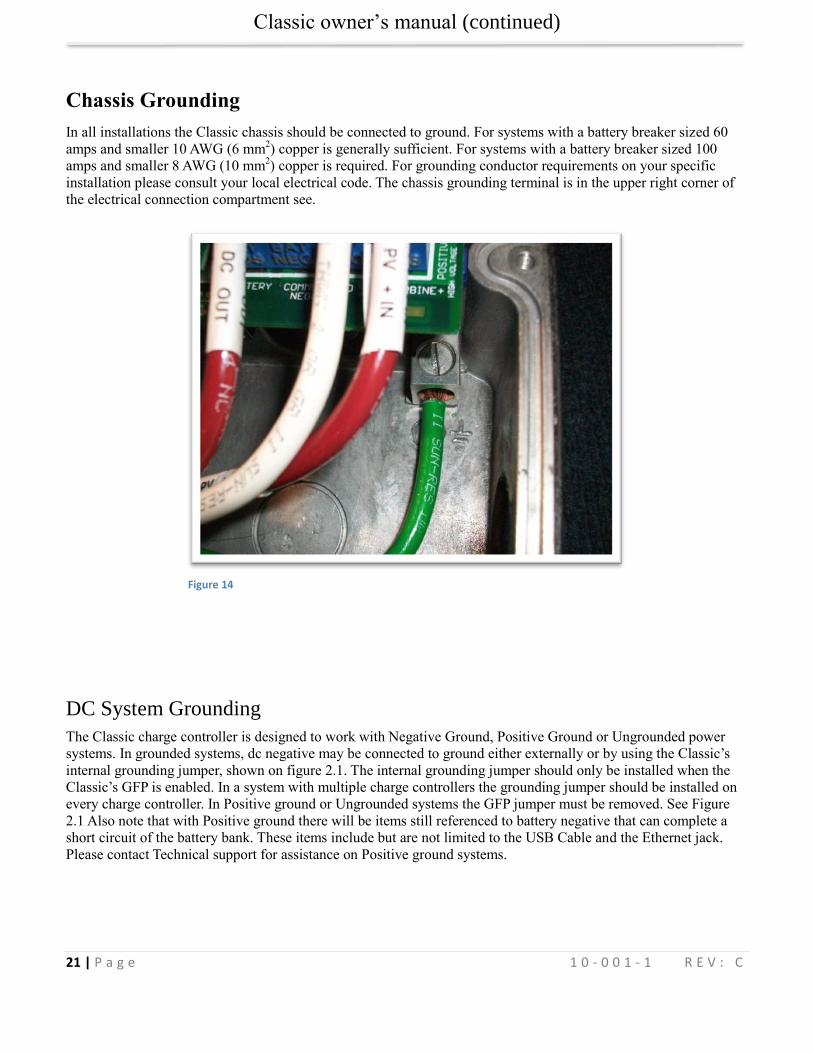
Chassis Grounding
In all installations the Classic chassis should be connected to ground. For systems with a battery breaker sized 60
amps and smaller 10 AWG (6 mm2) copper is generally sufficient. For systems with a battery breaker sized 100
amps and smaller 8 AWG (10 mm2) copper is required. For grounding conductor requirements on your specific
installation please consult your local electrical code. The chassis grounding terminal is in the upper right corner of
the electrical connection compartment see.
Figure 14
DC System Grounding
The Classic charge controller is designed to work with Negative Ground, Positive Ground or Ungrounded power
systems. In grounded systems, dc negative may be connected to ground either externally or by using the Classic’s
internal grounding jumper, shown on figure 2.1. The internal grounding jumper should only be installed when the
Classic’s GFP is enabled. In a system with multiple charge controllers the grounding jumper should be installed on
every charge controller. In Positive ground or Ungrounded systems the GFP jumper must be removed. See Figure
2.1 Also note that with Positive ground there will be items still referenced to battery negative that can complete a
short circuit of the battery bank. These items include but are not limited to the USB Cable and the Ethernet jack.
Please contact Technical support for assistance on Positive ground systems.
Classic owner’s manual (continued)
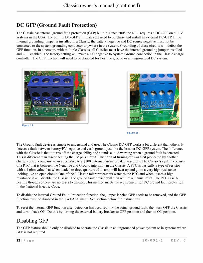
22 | P a g e 1 0 - 0 0 1 - 1 R E V : C
DC GFP (Ground Fault Protection)
The Classic has internal ground fault protection (GFP) built in. Since 2008 the NEC requires a DC-GFP on all PV
systems in the USA. The built in DC-GFP eliminates the need to purchase and install an external DC-GFP. If the
internal grounding jumper is installed in a Classic, the battery negative and DC source negative must not be
connected to the system grounding conductor anywhere in the system. Grounding of these circuits will defeat the
GFP function. In a network with multiple Classics, all Classics must have the internal grounding jumper installed
and GFP enabled. The factory setting will make a DC negative to System Ground connection in the Classic charge
controller. The GFP function will need to be disabled for Positive ground or an ungrounded DC system.
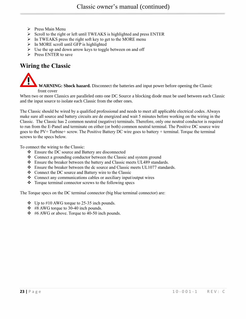
Figure 16
The Ground fault device is simple to understand and use. The Classic DC-GFP works a bit different than others. It
detects a fault between battery/PV negative and earth ground just like the breaker DC-GFP system. The difference
with the Classic is that it turns off the charge ability and sounds a loud warning when a ground fault is detected.
This is different than disconnecting the PV plus circuit. This trick of turning off was first pioneered by another
charge control company as an alternative to a $100 external circuit breaker assembly. The Classic’s system consists
of a PTC that is between the Negative and Ground internally in the Classic. A PTC is basically a type of resistor
with a 1 ohm value that when loaded to three quarters of an amp will heat up and go to a very high resistance
looking like an open circuit. One of the 3 Classic microprocessors watches the PTC and when it sees a high
resistance it will disable the Classic. The ground fault device will then require a manual reset. The PTC is self-
healing though so there are no fuses to change. This method meets the requirement for DC ground fault protection
in the National Electric Code.
To disable the internal Ground Fault Protection function, the jumper labeled GFP needs to be removed, and the GFP
function must be disabled in the TWEAKS menu. See section below for instructions.
To reset the internal GFP function after detection has occurred; fix the actual ground fault, then turn OFF the Classic
and turn it back ON. Do this by turning the external battery breaker to OFF position and then to ON position.
Disabling GFP
The GFP feature should only be disabled to operate the Classic in an ungrounded power system or in systems where
GFP is not required.
Figure 15
Classic owner’s manual (continued)
23 | P a g e 1 0 - 0 0 1 - 1 R E V : C
Press Main Menu
Scroll to the right or left until TWEAKS is highlighted and press ENTER
In TWEAKS press the right soft key to get to the MORE menu
In MORE scroll until GFP is highlighted
Use the up and down arrow keys to toggle between on and off
Press ENTER to save
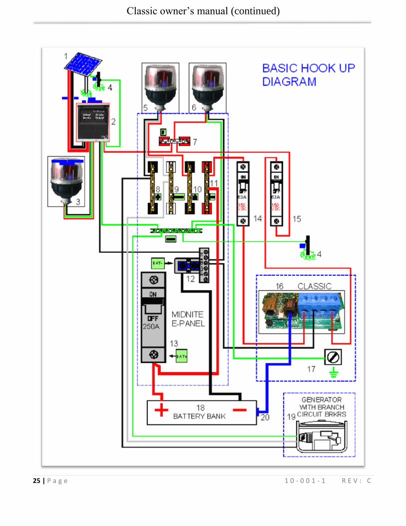
Wiring the Classic
WARNING: Shock hazard. Disconnect the batteries and input power before opening the Classic
front cover
When two or more Classics are paralleled onto one DC Source a blocking diode must be used between each Classic
and the input source to isolate each Classic from the other ones.
The Classic should be wired by a qualified professional and needs to meet all applicable electrical codes. Always
make sure all source and battery circuits are de energized and wait 5 minutes before working on the wiring in the
Classic. The Classic has 2 common neutral (negative) terminals. Therefore, only one neutral conductor is required
to run from the E-Panel and terminate on either (or both) common neutral terminal. The Positive DC source wire
goes to the PV+ Turbine+ screw. The Positive Battery DC wire goes to battery + terminal. Torque the terminal
screws to the specs below.
To connect the wiring to the Classic:
Ensure the DC source and Battery are disconnected
Connect a grounding conductor between the Classic and system ground
Ensure the breaker between the battery and Classic meets UL489 standards.
Ensure the breaker between the dc source and Classic meets UL1077 standards.
Connect the DC source and Battery wire to the Classic
Connect any communications cables or auxiliary input/output wires
Torque terminal connector screws to the following specs
The Torque specs on the DC terminal connector (big blue terminal connector) are:
Up to #10 AWG torque to 25-35 inch pounds.
#8 AWG torque to 30-40 inch pounds.
#6 AWG or above. Torque to 40-50 inch pounds.
Classic owner’s manual (continued)
24 | P a g e 1 0 - 0 0 1 - 1 R E V : C
Diagram 1
Classic owner’s manual (continued)
25 | P a g e 1 0 - 0 0 1 - 1 R E V : C
Classic owner’s manual (continued)
26 | P a g e 1 0 - 0 0 1 - 1 R E V : C
Diagram 2
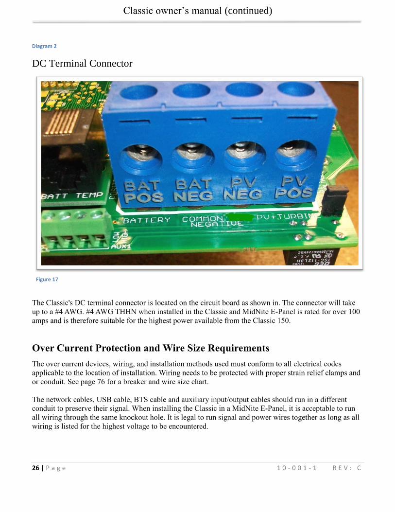
DC Terminal Connector
Figure 17
The Classic's DC terminal connector is located on the circuit board as shown in. The connector will take
up to a #4 AWG. #4 AWG THHN when installed in the Classic and MidNite E-Panel is rated for over 100
amps and is therefore suitable for the highest power available from the Classic 150.
Over Current Protection and Wire Size Requirements
The over current devices, wiring, and installation methods used must conform to all electrical codes
applicable to the location of installation. Wiring needs to be protected with proper strain relief clamps and
or conduit. See page 76 for a breaker and wire size chart.
The network cables, USB cable, BTS cable and auxiliary input/output cables should run in a different
conduit to preserve their signal. When installing the Classic in a MidNite E-Panel, it is acceptable to run
all wiring through the same knockout hole. It is legal to run signal and power wires together as long as all
wiring is listed for the highest voltage to be encountered.
Classic owner’s manual (continued)
27 | P a g e 1 0 - 0 0 1 - 1 R E V : C
Current Rating
The Classic limits the output current based on the model you have.
The Classic current ratings are:
Classic 150 + 150 Lite - 96 amps maximum
Classic 200 + 200 Lite - 79 amps maximum
Classic 250 + 250 Lite - 62 amps maximum
Classic 250ks + 250ks Lite – 58 amps maximum
Over Current Protection
The Classic must have over current protection to protect wiring from over current events. A means of
disconnect must be installed on the DC in and DC out of the Classic. Consult your local codes to
determine over current ratings. The breaker between the battery bank and the Classic must conform to
UL489. The breaker between the DC source and the Classic must conform to UL1077 or UL489. The
NEC requires 1.56 times short circuit current for PV over current protection. This is reduced to 1.25 times
when using a breaker rated for continuous duty. All MidNite Solar breakers are hydraulic/magnetic and
are rated for continuous duty. No de-rating is required for the output breaker when using MidNite Solar
breakers.
PV in particular will be capable of producing more current than its name plate rating in extreme situations
so the safe minimum wire size should be selected for the PV array maximum short circuit current. Please
consult PV manufacturer for specifications. The US National Electrical Code requires 1.56 times the PV
short circuit current for wire size on the PV input. Output wire size follows the NEC guidelines. Typical
wire size for output is 6AWG for the Classic250 and 4AWG for the Classic200 and 150 but check all de-
ratings for your wire type and installation method.
Long Distance Wire Runs
The Classic offers some unique opportunities if you are faced with longer than normal wire runs between
the DC source and the Classic. The Classic comes in 3 input voltage ranges letting you design a DC
source at a higher voltage if it is beneficial. For example let’s say you have a 300 ft run from a PV array to
the Classic you could wire for an open circuit voltage close to 250vdc accounting for the coldest
temperature you will encounter. This will allow you to run a smaller gauge wire than with a lower voltage
charge controller. The efficiency of a high voltage Classic is less than the lower voltage versions, so you
need to weigh the benefit. If this sounds too complicated use this rule of thumb in selecting the proper
Classic. PV runs up to 100 feet, use the Classic 150. Runs up to 180 feet, use the Classic 200. Above 180
feet use the Classic 250.
If the wire size between the DC source and the Classic is larger than the Classic's DC terminal connector
you can use a splicer block or similar connector to reduce down to #4 AWG close to the Classic. The
MidNite E-Panels are supplied with a PV input busbar that accepts up to 2/0 wire.
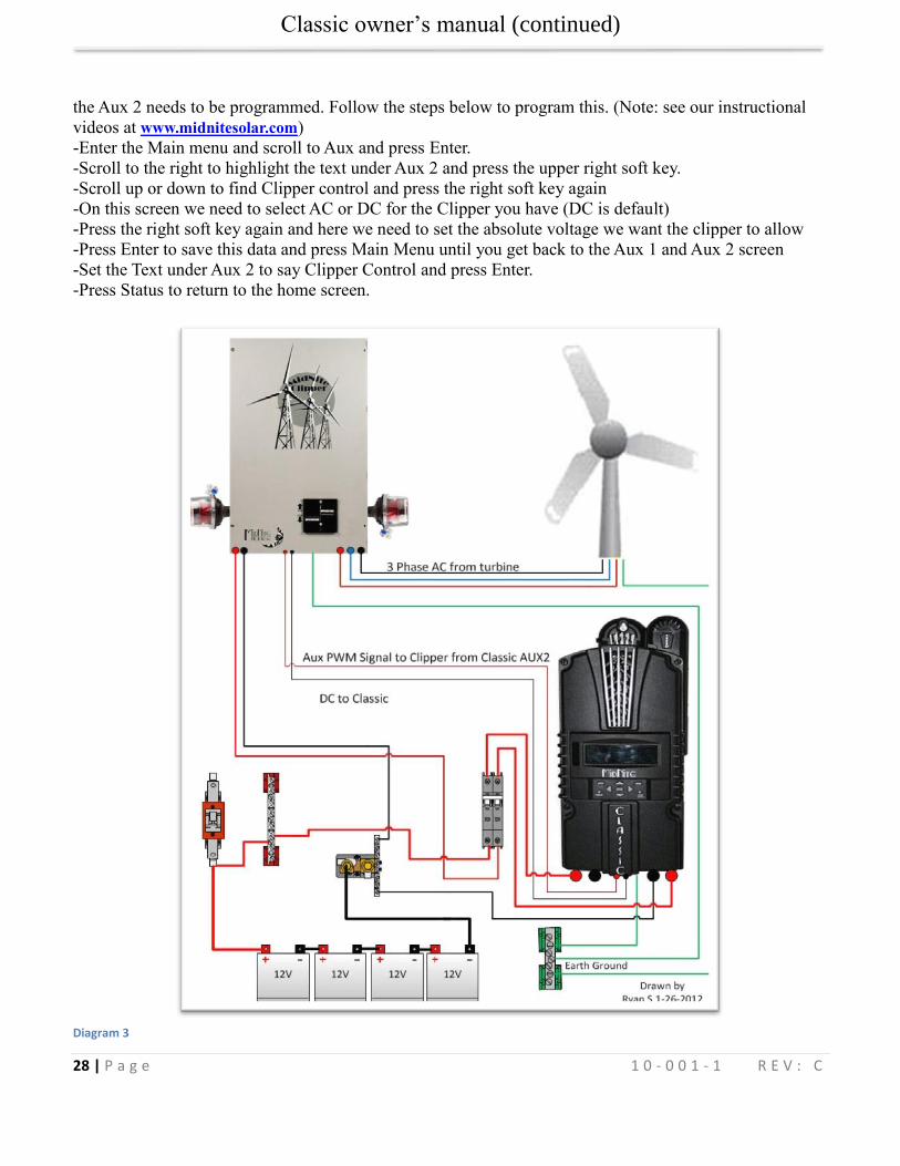
Connecting the Classic to the Clipper
The connections between the Clipper and Classic are fairly basic. There is the DC – and + conductors
from the Clipper to the PV input on the Classic. There is also a smaller set of – and + conductors
connecting Auxiliary 2 to the PWM input on the Clipper. To program the Classic to work with the Clipper
Classic owner’s manual (continued)
28 | P a g e 1 0 - 0 0 1 - 1 R E V : C
the Aux 2 needs to be programmed. Follow the steps below to program this. (Note: see our instructional
videos at www.midnitesolar.com)
-Enter the Main menu and scroll to Aux and press Enter.
-Scroll to the right to highlight the text under Aux 2 and press the upper right soft key.
-Scroll up or down to find Clipper control and press the right soft key again
-On this screen we need to select AC or DC for the Clipper you have (DC is default)
-Press the right soft key again and here we need to set the absolute voltage we want the clipper to allow
-Press Enter to save this data and press Main Menu until you get back to the Aux 1 and Aux 2 screen
-Set the Text under Aux 2 to say Clipper Control and press Enter.
-Press Status to return to the home screen.
Diagram 3
Classic owner’s manual (continued)
29 | P a g e 1 0 - 0 0 1 - 1 R E V : C
Maximum and Minimum Wire Size
The Classics Blue DC terminal connector will accept wire from #14-#4 AWG
The Classics Aux 1 and 2 terminal connector will accept wire up to #18 AWG
Equalization Manual and Auto
Equalization with the Classic Lite
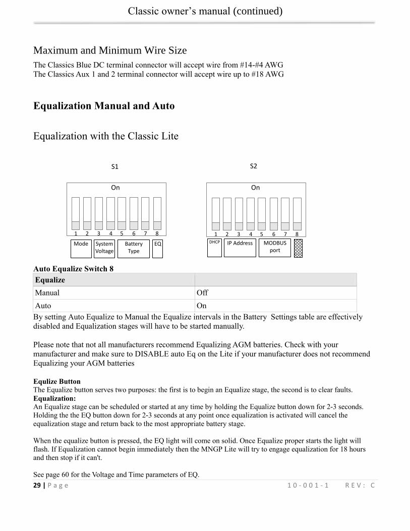
Auto Equalize Switch 8
Equalize
Manual Off
Auto On
By setting Auto Equalize to Manual the Equalize intervals in the Battery Settings table are effectively
disabled and Equalization stages will have to be started manually.
Please note that not all manufacturers recommend Equalizing AGM batteries. Check with your
manufacturer and make sure to DISABLE auto Eq on the Lite if your manufacturer does not recommend
Equalizing your AGM batteries
Equlize Button
The Equalize button serves two purposes: the first is to begin an Equalize stage, the second is to clear faults.
Equalization:
An Equalize stage can be scheduled or started at any time by holding the Equalize button down for 2-3 seconds.
Holding the the EQ button down for 2-3 seconds at any point once equalization is activated will cancel the
equalization stage and return back to the most appropriate battery stage.
When the equalize button is pressed, the EQ light will come on solid. Once Equalize proper starts the light will
flash. If Equalization cannot begin immediately then the MNGP Lite will try to engage equalization for 18 hours
and then stop if it can't.
See page 60 for the Voltage and Time parameters of EQ.
S1 S2
Mode System Voltage
Battery Type
EQ DHCP IP Address
MODBUS
port
1 2 3 4 5 6 7 8
On
1 2 3 4 5 6 7 8
On
Classic owner’s manual (continued)
30 | P a g e 1 0 - 0 0 1 - 1 R E V : C
Equalization with the standard Classic
Manual EQ To do a manual Equalization charge, Go into the Charge menu and highlight “EQ” and press “Enter”. Now “EQ Stopped” will be highlighted. Scroll up to select “Eq Started”. Press the “Status” button to return to the home screen. To stop a manual EQ in progress simply reverse the steps above. A manual EQ when started will last for that day unless the Classic is on say Hydro or Wind and the controller never goes to Resting that night, in this case it will stay in EQ until it completes or the controller goes to Resting.
Auto EQ The Classic can be set up to automatically equalize your batteries periodically, programmed as days between
Equalization and the number of days the Classic will try to finish the programmed equalization charge cycle.
To set up Auto EQ go into the CHARGE menu and highlight “EQ” and press “Enter”. Now press the SOFT RIGHT
key labeled "AUTO EQ". Pressing the AUTO EQ soft key enters the Auto EQ setup menu screen. The left side of
the EQ setup menu will show and select the number of days, or "interval” between auto EQ charge cycles. If set to
zero (0), it will display MANUAL which is the same thing as DISABLED.
Figure 18
On the right side of the Auto EQ setup menu is the number of DAYS that the Auto EQ will retry if it does not finish
the number of Hours and Minutes the Classic has been programmed to EQ for during the first day. For instance you
set the Auto EQ for an interval of every 30 days and the RE-TRY for 3 days. Then the first day it attempts an EQ the
Classic only accumulates 1 hour of a 2 hour EQ cycle, the next day the Classic will re attempt the EQ cycle. If the
Classic still didn't finish the EQ cycle on the 2nd day of its 3 allotted re-try days, it will have one more day to try to
finish the Equalize cycle. After this, if it did not complete the 2 hours of EQ time, it will not continue another day.
The Classic will show “EQ DONE" on the status screen until either the start of the next day or until the user presses
a button on the MNGP to stop it earlier.
At the bottom of the AUTO EQ screen shows the time, in hours and minutes, that the EQ is set for.
Pressing the Soft Right key, labeled "VIEW", takes you to a screen where you can view the interval and re-try
counters (timers).
Classic owner’s manual (continued)
31 | P a g e 1 0 - 0 0 1 - 1 R E V : C
Standard Classic programming
Commissioning the Classic (Quick Start)
The Classic will enter into the Quick Set screens upon initial power up. If the Classic does not enter into
the quick set or you want to restore to Factory Default follow these steps to get initiate a Quick Set.
With the power off to the Classic Hold the left and right arrow buttons down.
Turn the power on to the Classic and continue to hold the arrow buttons until the setup screen is
displayed.
Answer the questions on the next few screens to complete the Quick Set.
Battery Charge Stages and Meanings
Bulk MPPT
This stage of the Classic means; that the Classic will be putting out as much current as it can to raise the
battery voltage to the absorb voltage set point. This is also known as constant current mode.
Absorb
This stage means that the Classic will maintain the absorb set point voltage until the batteries are charged.
This stage is terminated at the end of the Absorb time or the End Amps set point whichever is reached
first. At this stage the classic is not putting out maximum current, as that would increase the battery
voltage over the Absorb set point. This is also referred to as constant voltage mode.
The absorb time is proportional to the bulk time. (i.e. the time bulk takes to reach the absorb voltage.) The
battery it’s considered “full” at the end of the absorb charge cycle.
Float
A Float cycle follows after the Absorb cycle is completed; Float is displayed on the screen. Battery
voltage is held at the float voltage set point.
Equalize
Equalization function can be manually initiated or can be set up to Auto Equalize, refer to page Error!
Bookmark not defined. for details on setting up EQ. The intent of an equalization charge is to bring all
battery cells to an equal voltage by a controller deliberate overcharge. The goal is to return each battery
cell to its optimum condition through a series of voltage controlled chemical reactions inside the batteries.
Resting
“Resting” will show on the display when the Classic is not charging the batteries, this is typically due to low light.
Classic owner’s manual (continued)
32 | P a g e 1 0 - 0 0 1 - 1 R E V : C
Mode is OFF
The Classic is unique, it has multiple charging algorithms for just about any DC input. Because we support such a
wide variety of DC inputs we have also added a software “ON” and “OFF” feature. This software “Switch”
basically turns the relay off effectively disconnecting the input source so the Classic will not charge the battery. If
you see “Mode is Off” in the bottom right corner of the display then the Mode may have got turned off. To turn the
mode back “ON” push the Main Menu button several times until “Wizard” is highlighted. Scroll to the right until
“Mode” is highlighted and press “Enter”. On this screen “OFF” should be highlighted use the up or down arrow to
change it to “ON” and press “Enter”. Press the Status button once to return to the main status screen.
Note: This is the same menu you would use to change between Charging algorithms IE Solar, Hydro etc
Adjusting Absorb, Equalize and Float Voltages
Absorb, Equalize and Float voltages are fully adjustable. You will need to get the actual voltages from the
battery manufacturer. To adjust these voltages follow the steps below.
Press Main Menu to enter the Main Menu
Scroll right or left until Charge is highlighted and push the Enter button
Highlight Volts and press the Enter button
Use left and right arrows keys to highlight the set point voltage to adjust
Use up and down arrow keys to lower or raise the voltage
Press the Enter button to save the new voltages.
Current Limit The Classic has a current limit component which interacts with the temperature of the charge controller.
If the Classic is exposed to extremely hot ambient conditions the output current will be reduced
automatically to keep the charge controller safe, if the orange LED comes on, on the MNGP it means that
the Classic is in current limit mode. If you believe the Classic is not hot and the orange LED is on, most
likely the current limit set point is too low. To check this follow steps bellow.
Press Main Menu
Highlight the CHARGE menu and press the Enter Button
Scroll to LIMITS and press the Enter Button
Press the right arrow key to highlight “Out Amps” or “In Amps” column
Use the up and down arrow keys to change the current limit then press the Enter Button to save
this data
Classic owner’s manual (continued)
33 | P a g e 1 0 - 0 0 1 - 1 R E V : C
LED Modes and the “Blinking Red LED”
The Classic may have a Red Blinking LED on its display. This has no effect on the Classic and simply
shows it is communicating with the Display. New Classics ship with this disabled. Below we will explain
the different LED Modes. To change the LED Mode press the “Main Menu” button repeatedly until
“Wizard” is highlighted. Scroll to the right until “Misc” is highlighted and press “Enter”. Now scroll to
“LED-Mode” and press “Enter”. Here you can use the up and down arrows to select the mode you prefer.
After selecting the appropriate LED Mode press “Enter” to save this data to the Classic. Pressing “Status”
will now bring you back to the home screen.
-OFF – No LED activity no matter what
-Rick Mode – LED Activity for Errors and Warnings only. (Over current, Arc Fault Etc)
-Blinky – basically cycles all the LEDs in a Disco fashion (Useful for Partys)
-LED 1 – LED activity for Warnings and Errors as well as info. A green LED on the display indicates the
Classic is in Float. A yellow LED on the display indicates a warning (Over Temp, over current etc). A red
LED on the Display indicates an Error (Arc Fault etc). There is also 3 LEDS inside the Classic that can be
viewed through the upper vents. The red LED indicates Auxiliary 1 is active. The blue LED is not used at
this time and the yellow LED indicates Auxiliary 2 is active
Calibrating Battery and PV Voltage
To calibrate the Classic battery and PV voltage reading, you will need a Volt meter to check the actual
battery bank voltage or input PV voltage. Using the volt meter measure the voltage on the DC terminal
connector of the Classic (refer to Figure 2.4) compare this reading to the reading on the Status screen in
the Classic,(press Status if not in this screen) to adjust the reading of the Classic to the one in the volt
meter follow these steps:
Press Main Menu, scroll to TWEAKS and press Enter
Highlight VBatt and use the up and down arrow keys to match both of the readings
Press the Enter button to save
Note. Use the description below to help complete the calibration of the Classic voltages.
TWEAKS screen
Battery voltage adjust
Battery voltage offset
Displayed battery voltage
Input voltage adjust
Input voltage offset
Displayed Input voltage Screenshot 1
Classic owner’s manual (continued)
34 | P a g e 1 0 - 0 0 1 - 1 R E V : C
Configuring DC Input Source
To select the Mode the Classic will run in, follow the steps below.
Push the Main Menu button.
Scroll left or right until Mode is highlighted and then push the Enter button.
Scroll to the right and highlight the current Mode than use the up and down arrows to set the
mode you want.
Take note of the Right soft key most modes have some set points that can be adjusted.
Press the Main Menu button until you get back to the Mode Menu
Set the ON/OFF to ON and press Enter
The following Modes will appear in this order in the MODE Menu.
Micro Hydro This mode is intended for use with hydro systems but can be used with other sources as well. When the
Classic first turns on after the input voltage goes above battery voltage, it will sweep from that open
circuit voltage down to battery voltage, finding the maximum power point voltage (MPP V). Then return
the input to that newly found voltage. After the original turn on sweep, the Classic will do mini sweeps at
user adjustable time intervals. If the time interval is set to 0, the Classic will not do any mini sweeps but
will stay on this first found MPP V until the user goes to the mode menu and turns it off and back on
again.
Micro Hydro mode sweeps slightly slower than Solar mode and has 2 user adjustable settings. Sweep
Interval is the time between mini-sweeps, in minutes, and sweeps around the present (i.e. the last found),
MPP Voltage. The range of this sweep is determined by the Sweep Depth user adjustment and is
expressed as a percentage of Watts that the sweep started from. For example, if in Micro Hydro mode, the
Classic was outputting 1000 Watts and the Sweep Depth percentage was set for 20%, (200 Watts), the
sweep will bring the input voltage DOWN until the output power drops down to 800 Watts, then will
sweep UP in voltage until the power drops again down to 800 Watts and then go back to the newly found
MPP Voltage, waiting for the next sweep.
Solar This is the default mode for PV systems and has a very fast sweep (typically1/2 second or less) that will
re-sweep at user adjustable sweep intervals, unless the Classic finds that it needs to do a sweep on its own
because of changing conditions. The timed sweep interval is user adjustable and is in units of
minutes. SOLAR mode is typically best for PV systems, especially if there is partial shading at times
during the day. The Classic will show a message of "PV SHADE" if it thinks the PV array is partially
shaded (if this feature is enabled).
SOLAR mode is best suited for shaded or un-shaded PV arrays that are at least one nominal voltage above
the battery voltage. For severe partial shading or PV arrays with nominal voltage equal to battery voltage,
you may also want to try Legacy P&O (Perturb and Observe) MPPT mode.
Legacy P&O
Classic owner’s manual (continued)
35 | P a g e 1 0 - 0 0 1 - 1 R E V : C
Legacy P&O (Perturb and Observe) mode is a slow tracking mode similar to the Micro Hydro mode but
with the difference that it is slightly faster and will shut off if the power source goes off.
It has 2 settings that are user adjustable. Sweep Interval is the time between mini-sweeps, in minutes, and
sweeps around the present (i.e. the last found), MPP Voltage. The range of this sweep is determined by
the Sweep Depth user adjustment and is expressed as a percentage of Watts that the sweep started
from. For example, if in Legacy P&O mode, the Classic was outputting 500 Watts and the Sweep Depth
percentage was set for 10%, (50 Watts), the sweep will bring the input voltage DOWN until the output
power drops down to 450 Watts, then will sweep UP in voltage until the power drops again down to 450
Watts and then go back to the newly found MPP Voltage, waiting for the next sweep.
Wind Track This mode uses a power curve that is either built by the user or one of the pre-installed graphs. The power
curve consists of 16 set points that consist of output amperage and input voltage, allowing the user to
custom build a curve for their Wind turbine. Please refer to the Wind section of the manual for full details
on programming the curve as well as our video that will help in understanding how to adjust these curves
using the wind graph editor.
Dynamic This is typically used for PV (solar) input sources and tries to follow, on a slow dynamic basis, the
changing conditions of the input source. This mode has one user adjustment which is a forced sweep
perturb trigger interval for times when the input condition changes do not trigger a dynamic sweep. The
interval is in units of minutes.
U-Set VOC% This is a fully manual mode based on a percentage of VOC. The Classic will sweep based on the user set
time in minutes and then park at a user set % of the VOC the Classic found on that sweep. This mode is
useful for testing or constant voltage sources.
Note: Mode must be manually turned ON after changing the mode. To turn the Mode on highlight the OFF
under ON/OFF and switch it to ON. Press enter to save this change.
Configuring the Classic for Wind Input Source
Wind
If you selected “Wind” you will need to select a power curve from the list of pre-loaded curves or build
your own. To access the list of power curves follow the steps below.
Push the Main Menu button.
Scroll left or right until “Mode” is highlighted and push the Enter button.
Set the status to OFF and then use the right soft key to select “Graph”.
Using the left soft key select “MEM”. Now you can scroll up and down through the menu and select from
the curve that was designed for your turbine. Once you find the correct power curve use the right soft key
Classic owner’s manual (continued)
36 | P a g e 1 0 - 0 0 1 - 1 R E V : C
to select “RECALL”. Now push the Enter button to save this power curve to the Classics memory.
There are also 9 memory spaces for you to save a custom power curve. To build custom power curves
select a memory location between 1 and 9 and hit “RECALL”. Use the right and left arrow buttons to
scroll through the 16 steps in the custom curve. On each step you can set the amperage by using the up
and down buttons. When you have the power curve the way you want it select “MEM”. Use the up and
down buttons to select a location 1 through 9 to save it in and select “SAVE”. Now push the Enter button
to save it to the Classic's memory.
For more information consult the videos contained in this DVD as well as the MidNite Solar web site.
Classic-Wind-Graph-Editor-1.mpg
Setting the Date and Time
To set the date and time manually on the Classic follow the steps below.
Push the Main Menu button repeatedly until Wizard is highlighted.
Scroll left or right to highlight “MISC” and push the Enter button
Scroll to “Time” and push Enter
Now scroll left or right to highlight the data you want to manually change. Use the up and down buttons to
change the data. When you have all the data changed push the Enter button to save the changes.
The Classic includes a battery in the MNGP portion, to keep the time running even when the power is
disconnected. To replace the battery refer to the Installation Manual
Setting Longitude and Latitude
With the built in virtual map, you are able to select where you are in the world. For a more precise setting
you can manually enter the longitude and latitude coordinates, geographic location is important because it
helps determine when the Classic wakes up and when it goes to sleep. This setting tells the Classic when
sunrise and sunset are to happen. The Classic will use this information on future features also. To set
longitude and latitude coordinates you need to go thought the WIZARD that is the only way to gain access
of this feature
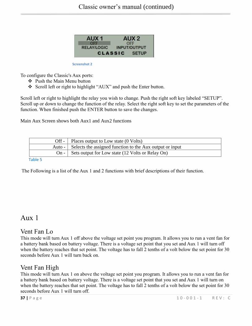
Configuring Auxiliary Input/Output
The Classic includes two auxiliary ports which can be configured to become inputs or outputs. These aux
ports can be used as a secondary power supply to be used for accessories such as vent-fan, anemometer
and generator starter or even and anemometer. The Aux output is limited to 200ma or less per channel.
These aux ports if used correctly could extend the system life. Here is an explanation of how they work.
An internal, re-settable Positive Temperature Co-efficient (PTC) fuse protects the AUX internal
components from overcurrent or a short circuit.
AUX 1 consists of either RELAY or LOGIC operation depending on the user selection function.
AUX 2 could be set to become an INPUT or OUTPUT. One at a time this port could be reading
the state of a device connected and takes an action from there.
Classic owner’s manual (continued)
37 | P a g e 1 0 - 0 0 1 - 1 R E V : C
To configure the Classic's Aux ports:
Push the Main Menu button
Scroll left or right to highlight “AUX” and push the Enter button.
Scroll left or right to highlight the relay you wish to change. Push the right soft key labeled “SETUP”.
Scroll up or down to change the function of the relay. Select the right soft key to set the parameters of the
function. When finished push the ENTER button to save the changes.
Main Aux Screen shows both Aux1 and Aux2 functions
Off - Places output to Low state (0 Volts)
Auto - Selects the assigned function to the Aux output or input
On - Sets output for Low state (12 Volts or Relay On)
Table 5
The Following is a list of the Aux 1 and 2 functions with brief descriptions of their function.
Aux 1
Vent Fan Lo This mode will turn Aux 1 off above the voltage set point you program. It allows you to run a vent fan for
a battery bank based on battery voltage. There is a voltage set point that you set and Aux 1 will turn off
when the battery reaches that set point. The voltage has to fall 2 tenths of a volt below the set point for 30
seconds before Aux 1 will turn back on.
Vent Fan High This mode will turn Aux 1 on above the voltage set point you program. It allows you to run a vent fan for
a battery bank based on battery voltage. There is a voltage set point that you set and Aux 1 will turn on
when the battery reaches that set point. The voltage has to fall 2 tenths of a volt below the set point for 30
seconds before Aux 1 will turn off.
Screenshot 2
Classic owner’s manual (continued)
38 | P a g e 1 0 - 0 0 1 - 1 R E V : C
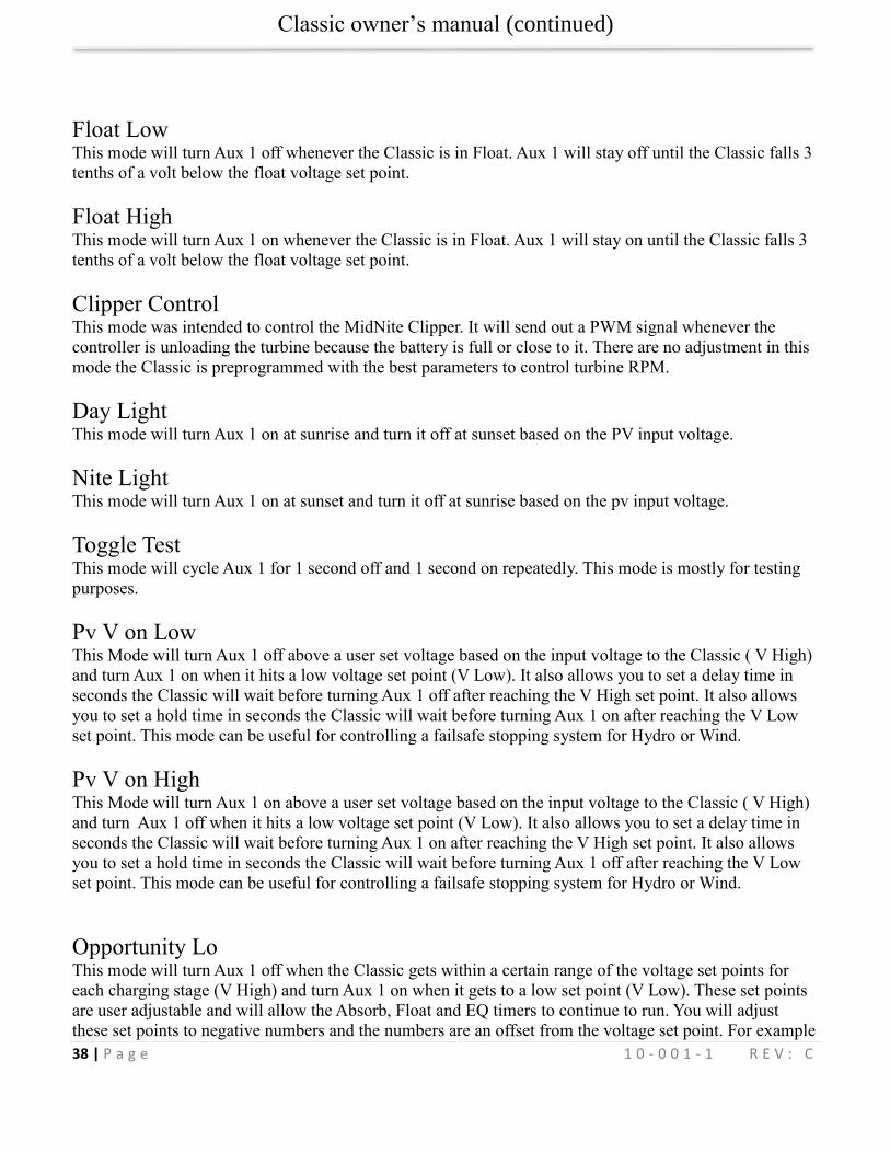
Float Low This mode will turn Aux 1 off whenever the Classic is in Float. Aux 1 will stay off until the Classic falls 3
tenths of a volt below the float voltage set point.
Float High This mode will turn Aux 1 on whenever the Classic is in Float. Aux 1 will stay on until the Classic falls 3
tenths of a volt below the float voltage set point.
Clipper Control This mode was intended to control the MidNite Clipper. It will send out a PWM signal whenever the
controller is unloading the turbine because the battery is full or close to it. There are no adjustment in this
mode the Classic is preprogrammed with the best parameters to control turbine RPM.
Day Light This mode will turn Aux 1 on at sunrise and turn it off at sunset based on the PV input voltage.
Nite Light This mode will turn Aux 1 on at sunset and turn it off at sunrise based on the pv input voltage.
Toggle Test This mode will cycle Aux 1 for 1 second off and 1 second on repeatedly. This mode is mostly for testing
purposes.
Pv V on Low This Mode will turn Aux 1 off above a user set voltage based on the input voltage to the Classic ( V High)
and turn Aux 1 on when it hits a low voltage set point (V Low). It also allows you to set a delay time in
seconds the Classic will wait before turning Aux 1 off after reaching the V High set point. It also allows
you to set a hold time in seconds the Classic will wait before turning Aux 1 on after reaching the V Low
set point. This mode can be useful for controlling a failsafe stopping system for Hydro or Wind.
Pv V on High This Mode will turn Aux 1 on above a user set voltage based on the input voltage to the Classic ( V High)
and turn Aux 1 off when it hits a low voltage set point (V Low). It also allows you to set a delay time in
seconds the Classic will wait before turning Aux 1 on after reaching the V High set point. It also allows
you to set a hold time in seconds the Classic will wait before turning Aux 1 off after reaching the V Low
set point. This mode can be useful for controlling a failsafe stopping system for Hydro or Wind.
Opportunity Lo This mode will turn Aux 1 off when the Classic gets within a certain range of the voltage set points for
each charging stage (V High) and turn Aux 1 on when it gets to a low set point (V Low). These set points
are user adjustable and will allow the Absorb, Float and EQ timers to continue to run. You will adjust
these set points to negative numbers and the numbers are an offset from the voltage set point. For example
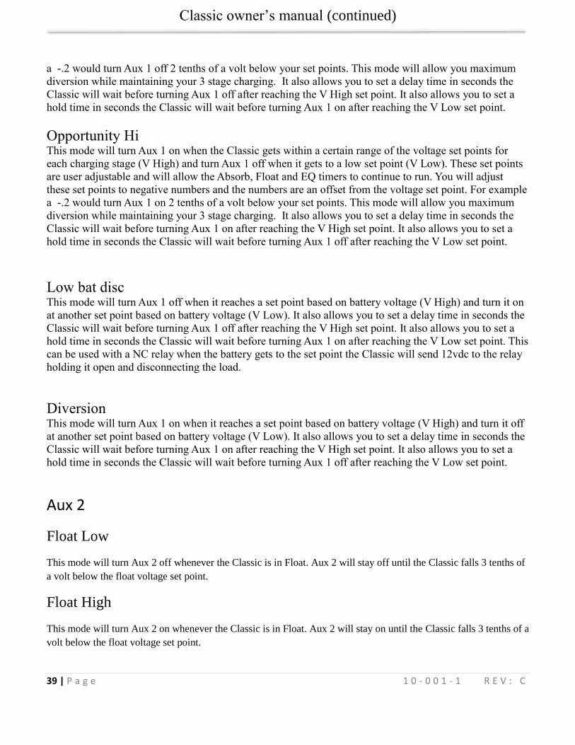
Classic owner’s manual (continued)
39 | P a g e 1 0 - 0 0 1 - 1 R E V : C
a -.2 would turn Aux 1 off 2 tenths of a volt below your set points. This mode will allow you maximum
diversion while maintaining your 3 stage charging. It also allows you to set a delay time in seconds the
Classic will wait before turning Aux 1 off after reaching the V High set point. It also allows you to set a
hold time in seconds the Classic will wait before turning Aux 1 on after reaching the V Low set point.
Opportunity Hi This mode will turn Aux 1 on when the Classic gets within a certain range of the voltage set points for
each charging stage (V High) and turn Aux 1 off when it gets to a low set point (V Low). These set points
are user adjustable and will allow the Absorb, Float and EQ timers to continue to run. You will adjust
these set points to negative numbers and the numbers are an offset from the voltage set point. For example
a -.2 would turn Aux 1 on 2 tenths of a volt below your set points. This mode will allow you maximum
diversion while maintaining your 3 stage charging. It also allows you to set a delay time in seconds the
Classic will wait before turning Aux 1 on after reaching the V High set point. It also allows you to set a
hold time in seconds the Classic will wait before turning Aux 1 off after reaching the V Low set point.
Low bat disc This mode will turn Aux 1 off when it reaches a set point based on battery voltage (V High) and turn it on
at another set point based on battery voltage (V Low). It also allows you to set a delay time in seconds the
Classic will wait before turning Aux 1 off after reaching the V High set point. It also allows you to set a
hold time in seconds the Classic will wait before turning Aux 1 on after reaching the V Low set point. This
can be used with a NC relay when the battery gets to the set point the Classic will send 12vdc to the relay
holding it open and disconnecting the load.
Diversion This mode will turn Aux 1 on when it reaches a set point based on battery voltage (V High) and turn it off
at another set point based on battery voltage (V Low). It also allows you to set a delay time in seconds the
Classic will wait before turning Aux 1 on after reaching the V High set point. It also allows you to set a
hold time in seconds the Classic will wait before turning Aux 1 off after reaching the V Low set point.
Aux 2
Float Low
This mode will turn Aux 2 off whenever the Classic is in Float. Aux 2 will stay off until the Classic falls 3 tenths of
a volt below the float voltage set point.
Float High
This mode will turn Aux 2 on whenever the Classic is in Float. Aux 2 will stay on until the Classic falls 3 tenths of a
volt below the float voltage set point.
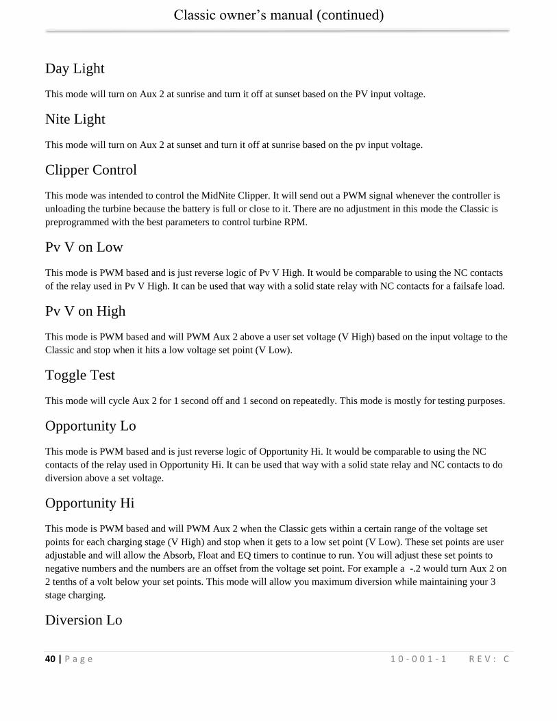
Classic owner’s manual (continued)
40 | P a g e 1 0 - 0 0 1 - 1 R E V : C
Day Light
This mode will turn on Aux 2 at sunrise and turn it off at sunset based on the PV input voltage.
Nite Light
This mode will turn on Aux 2 at sunset and turn it off at sunrise based on the pv input voltage.
Clipper Control
This mode was intended to control the MidNite Clipper. It will send out a PWM signal whenever the controller is
unloading the turbine because the battery is full or close to it. There are no adjustment in this mode the Classic is
preprogrammed with the best parameters to control turbine RPM.
Pv V on Low
This mode is PWM based and is just reverse logic of Pv V High. It would be comparable to using the NC contacts
of the relay used in Pv V High. It can be used that way with a solid state relay with NC contacts for a failsafe load.
Pv V on High
This mode is PWM based and will PWM Aux 2 above a user set voltage (V High) based on the input voltage to the
Classic and stop when it hits a low voltage set point (V Low).
Toggle Test
This mode will cycle Aux 2 for 1 second off and 1 second on repeatedly. This mode is mostly for testing purposes.
Opportunity Lo
This mode is PWM based and is just reverse logic of Opportunity Hi. It would be comparable to using the NC
contacts of the relay used in Opportunity Hi. It can be used that way with a solid state relay and NC contacts to do
diversion above a set voltage.
Opportunity Hi
This mode is PWM based and will PWM Aux 2 when the Classic gets within a certain range of the voltage set
points for each charging stage (V High) and stop when it gets to a low set point (V Low). These set points are user
adjustable and will allow the Absorb, Float and EQ timers to continue to run. You will adjust these set points to
negative numbers and the numbers are an offset from the voltage set point. For example a -.2 would turn Aux 2 on
2 tenths of a volt below your set points. This mode will allow you maximum diversion while maintaining your 3
stage charging.
Diversion Lo
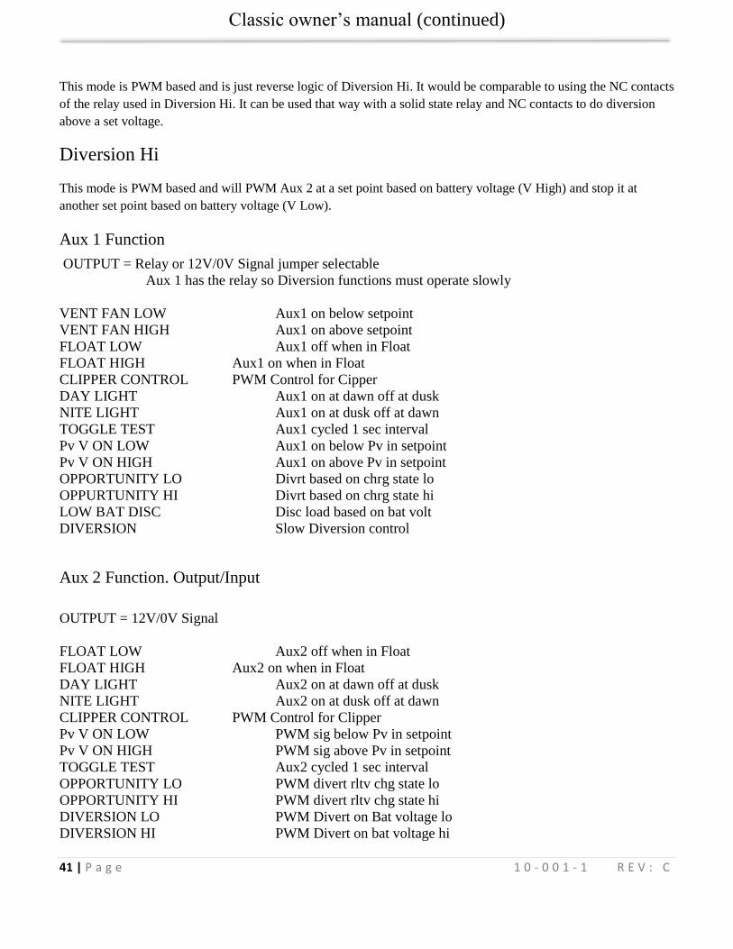
Classic owner’s manual (continued)
41 | P a g e 1 0 - 0 0 1 - 1 R E V : C
This mode is PWM based and is just reverse logic of Diversion Hi. It would be comparable to using the NC contacts
of the relay used in Diversion Hi. It can be used that way with a solid state relay and NC contacts to do diversion
above a set voltage.
Diversion Hi
This mode is PWM based and will PWM Aux 2 at a set point based on battery voltage (V High) and stop it at
another set point based on battery voltage (V Low).
Aux 1 Function
OUTPUT = Relay or 12V/0V Signal jumper selectable
Aux 1 has the relay so Diversion functions must operate slowly
VENT FAN LOW Aux1 on below setpoint
VENT FAN HIGH Aux1 on above setpoint
FLOAT LOW Aux1 off when in Float
FLOAT HIGH Aux1 on when in Float
CLIPPER CONTROL PWM Control for Cipper
DAY LIGHT Aux1 on at dawn off at dusk
NITE LIGHT Aux1 on at dusk off at dawn
TOGGLE TEST Aux1 cycled 1 sec interval
Pv V ON LOW Aux1 on below Pv in setpoint
Pv V ON HIGH Aux1 on above Pv in setpoint
OPPORTUNITY LO Divrt based on chrg state lo
OPPURTUNITY HI Divrt based on chrg state hi
LOW BAT DISC Disc load based on bat volt
DIVERSION Slow Diversion control
Aux 2 Function. Output/Input
OUTPUT = 12V/0V Signal
FLOAT LOW Aux2 off when in Float
FLOAT HIGH Aux2 on when in Float
DAY LIGHT Aux2 on at dawn off at dusk
NITE LIGHT Aux2 on at dusk off at dawn
CLIPPER CONTROL PWM Control for Clipper
Pv V ON LOW PWM sig below Pv in setpoint
Pv V ON HIGH PWM sig above Pv in setpoint
TOGGLE TEST Aux2 cycled 1 sec interval
OPPORTUNITY LO PWM divert rltv chg state lo
OPPORTUNITY HI PWM divert rltv chg state hi
DIVERSION LO PWM Divert on Bat voltage lo
DIVERSION HI PWM Divert on bat voltage hi
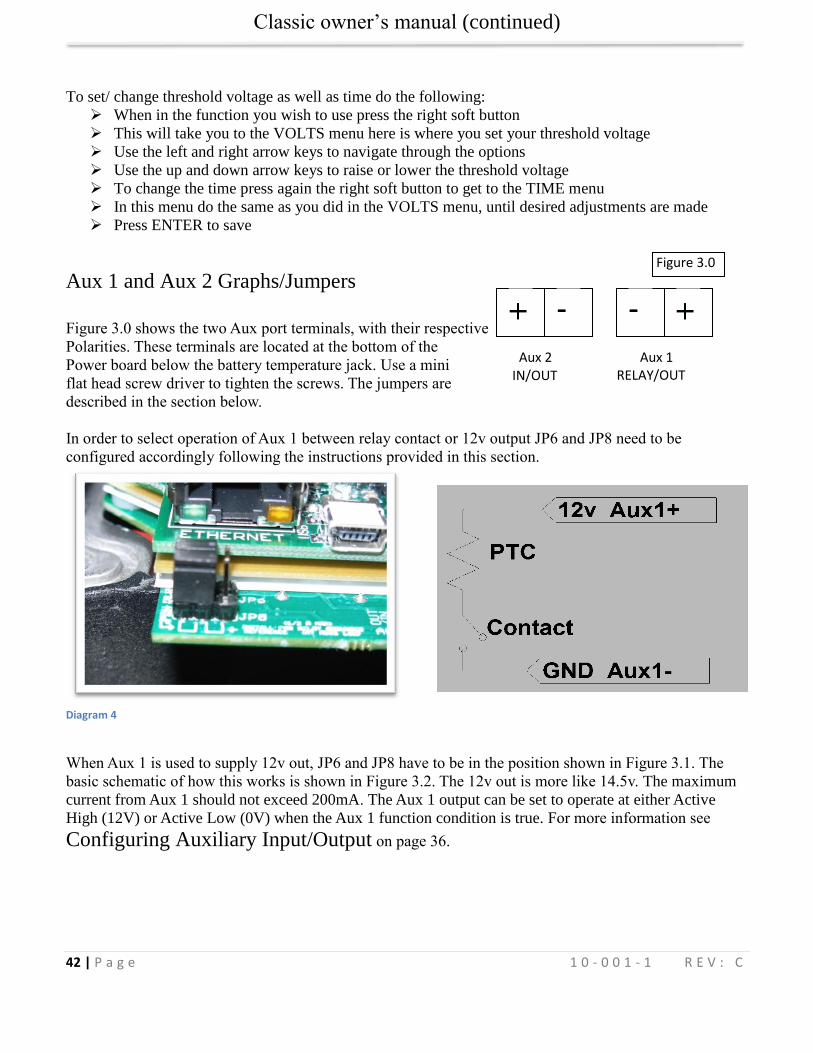
Classic owner’s manual (continued)
42 | P a g e 1 0 - 0 0 1 - 1 R E V : C
Aux 2 IN/OUT
- -
Aux 1 RELAY/OUT
To set/ change threshold voltage as well as time do the following:
When in the function you wish to use press the right soft button
This will take you to the VOLTS menu here is where you set your threshold voltage
Use the left and right arrow keys to navigate through the options
Use the up and down arrow keys to raise or lower the threshold voltage
To change the time press again the right soft button to get to the TIME menu
In this menu do the same as you did in the VOLTS menu, until desired adjustments are made
Press ENTER to save
Aux 1 and Aux 2 Graphs/Jumpers
Figure 3.0 shows the two Aux port terminals, with their respective
Polarities. These terminals are located at the bottom of the
Power board below the battery temperature jack. Use a mini
flat head screw driver to tighten the screws. The jumpers are
described in the section below.
In order to select operation of Aux 1 between relay contact or 12v output JP6 and JP8 need to be
configured accordingly following the instructions provided in this section.
Diagram 4
When Aux 1 is used to supply 12v out, JP6 and JP8 have to be in the position shown in Figure 3.1. The
basic schematic of how this works is shown in Figure 3.2. The 12v out is more like 14.5v. The maximum
current from Aux 1 should not exceed 200mA. The Aux 1 output can be set to operate at either Active
High (12V) or Active Low (0V) when the Aux 1 function condition is true. For more information see
Configuring Auxiliary Input/Output on page 36.
Figure 3.0
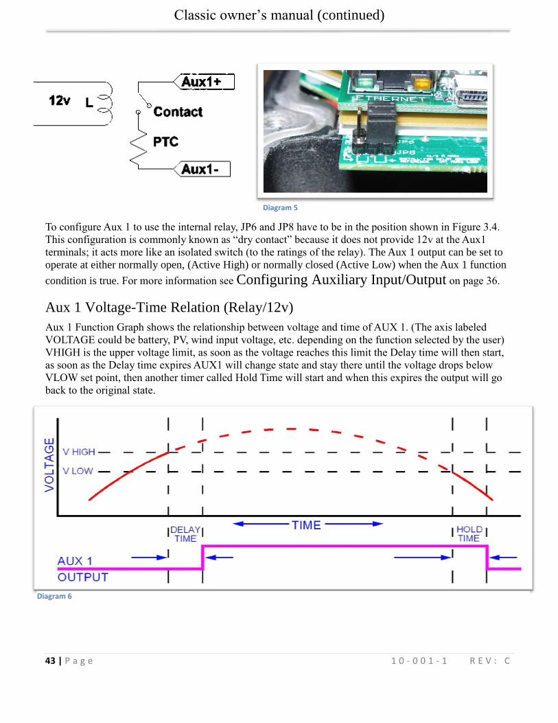
Classic owner’s manual (continued)
43 | P a g e 1 0 - 0 0 1 - 1 R E V : C
To configure Aux 1 to use the internal relay, JP6 and JP8 have to be in the position shown in Figure 3.4.
This configuration is commonly known as “dry contact” because it does not provide 12v at the Aux1
terminals; it acts more like an isolated switch (to the ratings of the relay). The Aux 1 output can be set to
operate at either normally open, (Active High) or normally closed (Active Low) when the Aux 1 function
condition is true. For more information see Configuring Auxiliary Input/Output on page 36.
Aux 1 Voltage-Time Relation (Relay/12v)
Aux 1 Function Graph shows the relationship between voltage and time of AUX 1. (The axis labeled
VOLTAGE could be battery, PV, wind input voltage, etc. depending on the function selected by the user)
VHIGH is the upper voltage limit, as soon as the voltage reaches this limit the Delay time will then start,
as soon as the Delay time expires AUX1 will change state and stay there until the voltage drops below
VLOW set point, then another timer called Hold Time will start and when this expires the output will go
back to the original state.
Diagram 5
Diagram 6
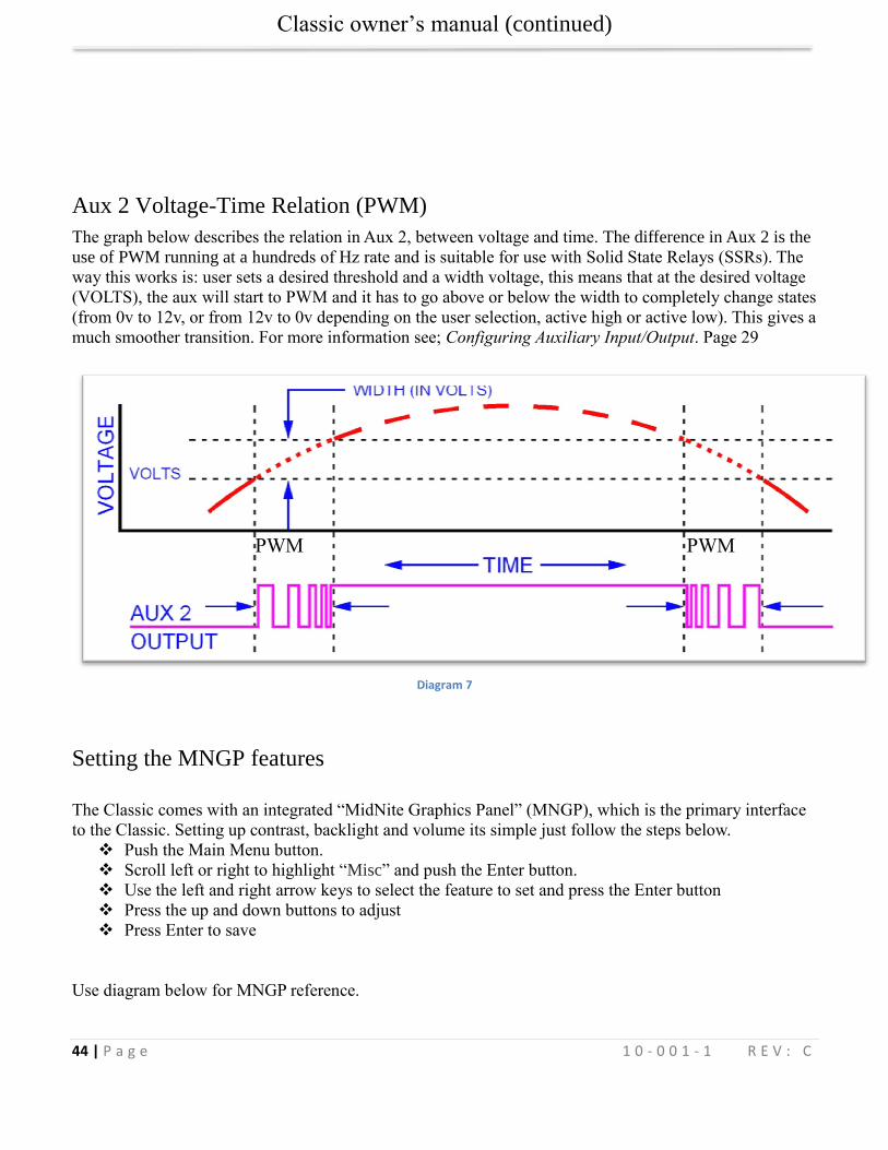
Classic owner’s manual (continued)
44 | P a g e 1 0 - 0 0 1 - 1 R E V : C
Aux 2 Voltage-Time Relation (PWM)
The graph below describes the relation in Aux 2, between voltage and time. The difference in Aux 2 is the
use of PWM running at a hundreds of Hz rate and is suitable for use with Solid State Relays (SSRs). The
way this works is: user sets a desired threshold and a width voltage, this means that at the desired voltage
(VOLTS), the aux will start to PWM and it has to go above or below the width to completely change states
(from 0v to 12v, or from 12v to 0v depending on the user selection, active high or active low). This gives a
much smoother transition. For more information see; Configuring Auxiliary Input/Output. Page 29
Diagram 7
Setting the MNGP features
The Classic comes with an integrated “MidNite Graphics Panel” (MNGP), which is the primary interface
to the Classic. Setting up contrast, backlight and volume its simple just follow the steps below.
Push the Main Menu button.
Scroll left or right to highlight “Misc” and push the Enter button.
Use the left and right arrow keys to select the feature to set and press the Enter button
Press the up and down buttons to adjust
Press Enter to save
Use diagram below for MNGP reference.
PWM PWM
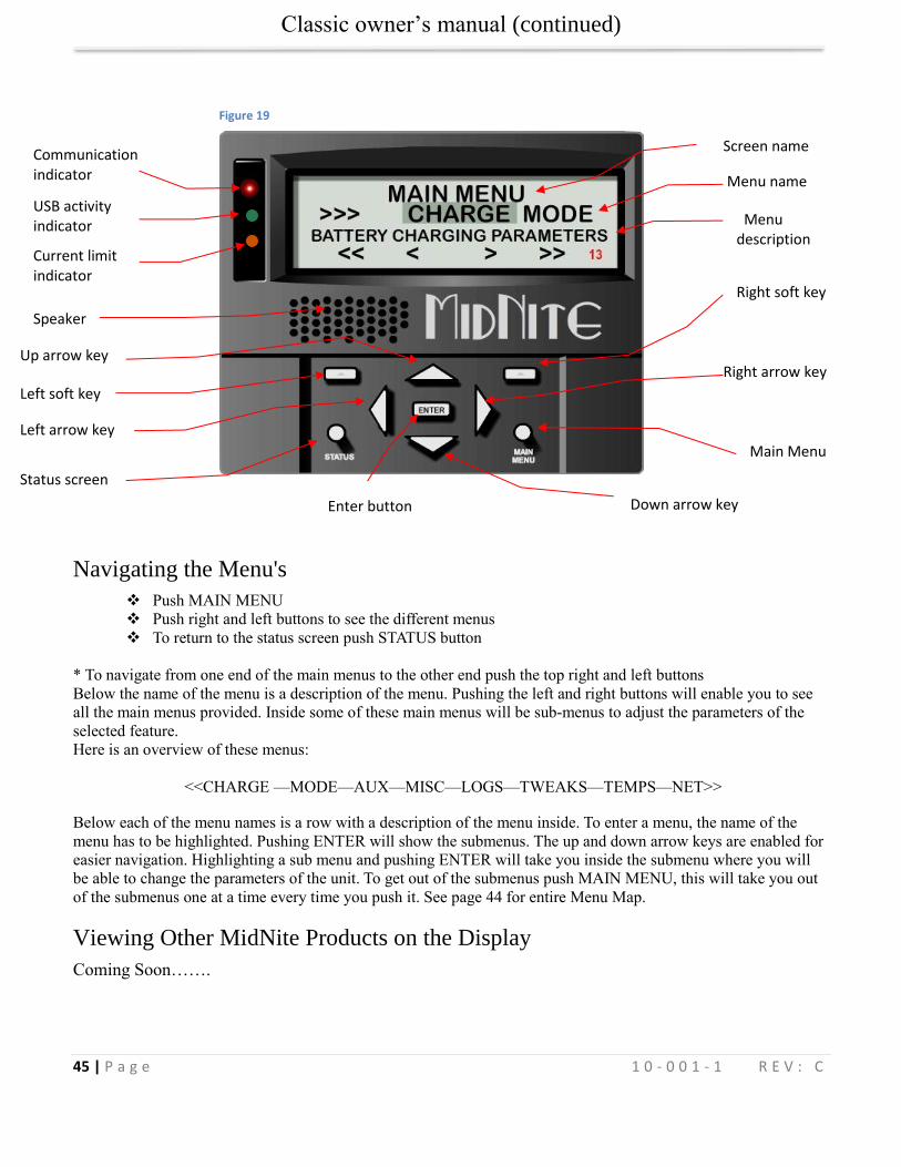
Classic owner’s manual (continued)
45 | P a g e 1 0 - 0 0 1 - 1 R E V : C
Navigating the Menu's
Push MAIN MENU
Push right and left buttons to see the different menus
To return to the status screen push STATUS button
* To navigate from one end of the main menus to the other end push the top right and left buttons
Below the name of the menu is a description of the menu. Pushing the left and right buttons will enable you to see
all the main menus provided. Inside some of these main menus will be sub-menus to adjust the parameters of the
selected feature.
Here is an overview of these menus:
<<CHARGE —MODE—AUX—MISC—LOGS—TWEAKS—TEMPS—NET>>
Below each of the menu names is a row with a description of the menu inside. To enter a menu, the name of the
menu has to be highlighted. Pushing ENTER will show the submenus. The up and down arrow keys are enabled for
easier navigation. Highlighting a sub menu and pushing ENTER will take you inside the submenu where you will
be able to change the parameters of the unit. To get out of the submenus push MAIN MENU, this will take you out
of the submenus one at a time every time you push it. See page 44 for entire Menu Map.
Viewing Other MidNite Products on the Display
Coming Soon…….
Down arrow key
Main Menu
Right arrow key
Right soft key
Up arrow key
Left soft key
Left arrow key
Status screen
Enter button
Current limit indicator
Speaker
USB activity indicator
Communication indicator
Menu description
Screen name
Menu name
Figure 19
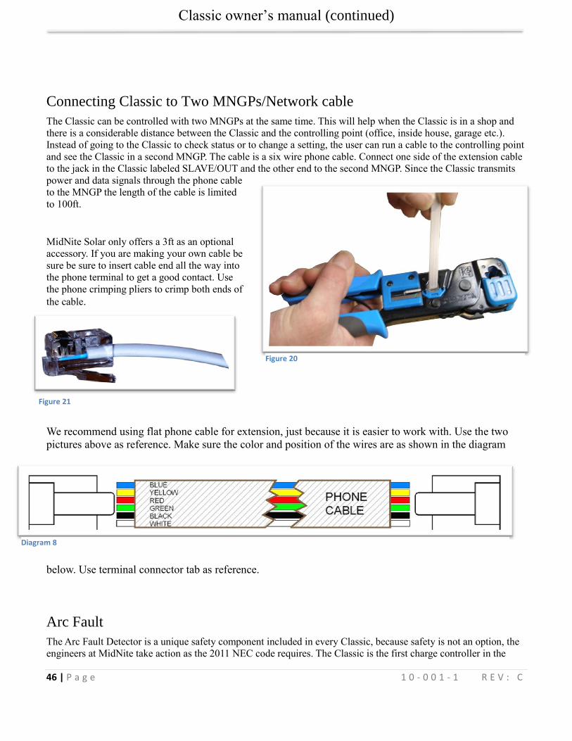
Classic owner’s manual (continued)
46 | P a g e 1 0 - 0 0 1 - 1 R E V : C
Connecting Classic to Two MNGPs/Network cable
The Classic can be controlled with two MNGPs at the same time. This will help when the Classic is in a shop and
there is a considerable distance between the Classic and the controlling point (office, inside house, garage etc.).
Instead of going to the Classic to check status or to change a setting, the user can run a cable to the controlling point
and see the Classic in a second MNGP. The cable is a six wire phone cable. Connect one side of the extension cable
to the jack in the Classic labeled SLAVE/OUT and the other end to the second MNGP. Since the Classic transmits
power and data signals through the phone cable
to the MNGP the length of the cable is limited
to 100ft.
MidNite Solar only offers a 3ft as an optional
accessory. If you are making your own cable be
sure be sure to insert cable end all the way into
the phone terminal to get a good contact. Use
the phone crimping pliers to crimp both ends of
the cable.
We recommend using flat phone cable for extension, just because it is easier to work with. Use the two
pictures above as reference. Make sure the color and position of the wires are as shown in the diagram
below. Use terminal connector tab as reference.
Arc Fault
The Arc Fault Detector is a unique safety component included in every Classic, because safety is not an option, the
engineers at MidNite take action as the 2011 NEC code requires. The Classic is the first charge controller in the
Figure 21
Figure 20
Diagram 8
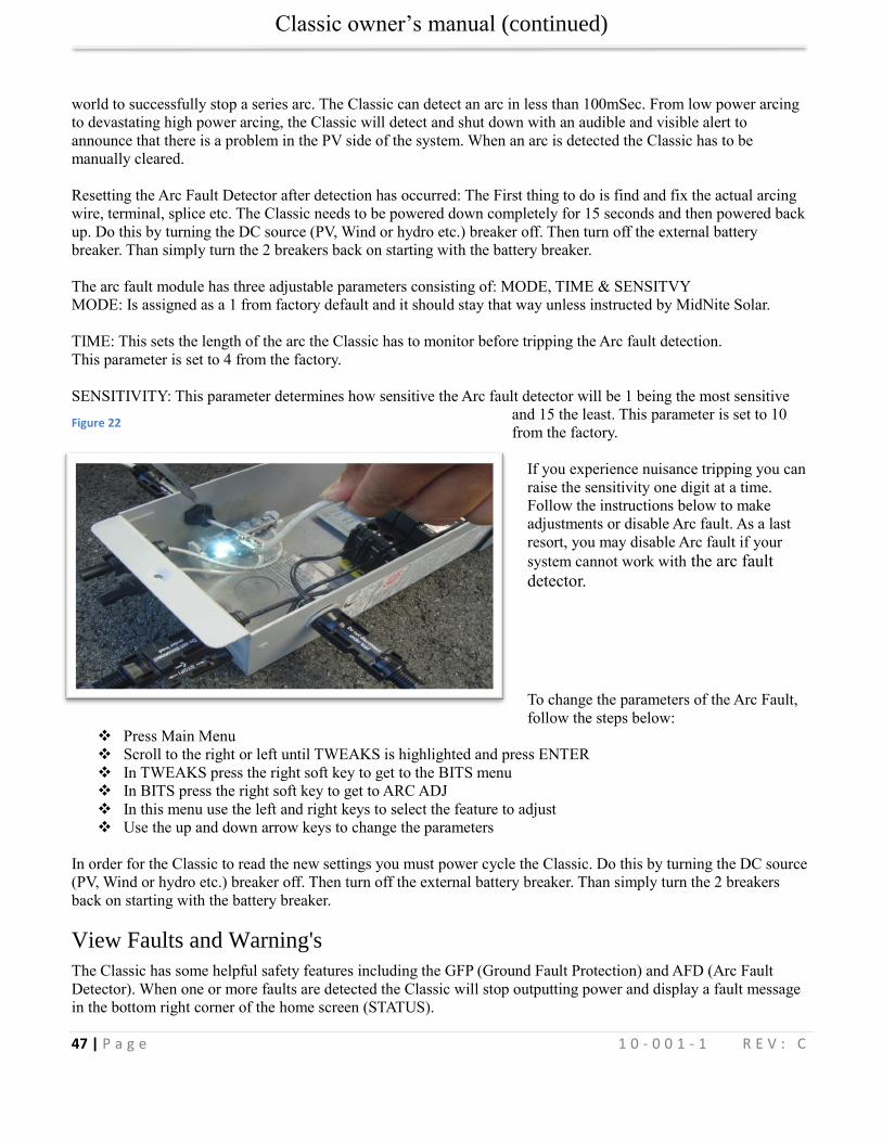
Classic owner’s manual (continued)
47 | P a g e 1 0 - 0 0 1 - 1 R E V : C
world to successfully stop a series arc. The Classic can detect an arc in less than 100mSec. From low power arcing
to devastating high power arcing, the Classic will detect and shut down with an audible and visible alert to
announce that there is a problem in the PV side of the system. When an arc is detected the Classic has to be
manually cleared.
Resetting the Arc Fault Detector after detection has occurred: The First thing to do is find and fix the actual arcing
wire, terminal, splice etc. The Classic needs to be powered down completely for 15 seconds and then powered back
up. Do this by turning the DC source (PV, Wind or hydro etc.) breaker off. Then turn off the external battery
breaker. Than simply turn the 2 breakers back on starting with the battery breaker.
The arc fault module has three adjustable parameters consisting of: MODE, TIME & SENSITVY
MODE: Is assigned as a 1 from factory default and it should stay that way unless instructed by MidNite Solar.
TIME: This sets the length of the arc the Classic has to monitor before tripping the Arc fault detection.
This parameter is set to 4 from the factory.
SENSITIVITY: This parameter determines how sensitive the Arc fault detector will be 1 being the most sensitive
and 15 the least. This parameter is set to 10
from the factory.
If you experience nuisance tripping you can
raise the sensitivity one digit at a time.
Follow the instructions below to make
adjustments or disable Arc fault. As a last
resort, you may disable Arc fault if your
system cannot work with the arc fault
detector.
To change the parameters of the Arc Fault,
follow the steps below:
Press Main Menu
Scroll to the right or left until TWEAKS is highlighted and press ENTER
In TWEAKS press the right soft key to get to the BITS menu
In BITS press the right soft key to get to ARC ADJ
In this menu use the left and right keys to select the feature to adjust
Use the up and down arrow keys to change the parameters
In order for the Classic to read the new settings you must power cycle the Classic. Do this by turning the DC source
(PV, Wind or hydro etc.) breaker off. Then turn off the external battery breaker. Than simply turn the 2 breakers
back on starting with the battery breaker.
View Faults and Warning's
The Classic has some helpful safety features including the GFP (Ground Fault Protection) and AFD (Arc Fault
Detector). When one or more faults are detected the Classic will stop outputting power and display a fault message
in the bottom right corner of the home screen (STATUS).
Figure 22
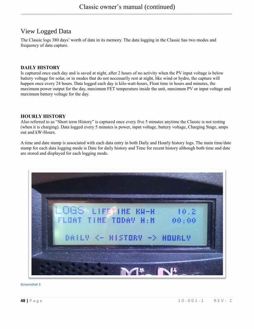
Classic owner’s manual (continued)
48 | P a g e 1 0 - 0 0 1 - 1 R E V : C
View Logged Data
The Classic logs 380 days’ worth of data in its memory. The data logging in the Classic has two modes and
frequency of data capture.
DAILY HISTORY Is captured once each day and is saved at night, after 2 hours of no activity when the PV input voltage is below
battery voltage for solar, or in modes that do not necessarily rest at night, like wind or hydro, the capture will
happen once every 24 hours. Data logged each day is kilo-watt-hours, Float time in hours and minutes, the
maximum power output for the day, maximum FET temperature inside the unit, maximum PV or input voltage and
maximum battery voltage for the day.
HOURLY HISTORY Also referred to as “Short term History” is captured once every five 5 minutes anytime the Classic is not resting
(when it is charging). Data logged every 5 minutes is power, input voltage, battery voltage, Charging Stage, amps
out and kW-Hours.
A time and date stamp is associated with each data entry in both Daily and Hourly history logs. The main time/date
stamp for each data logging mode is Date for daily history and Time for recent history although both time and date
are stored and displayed for each logging mode.
Screenshot 3
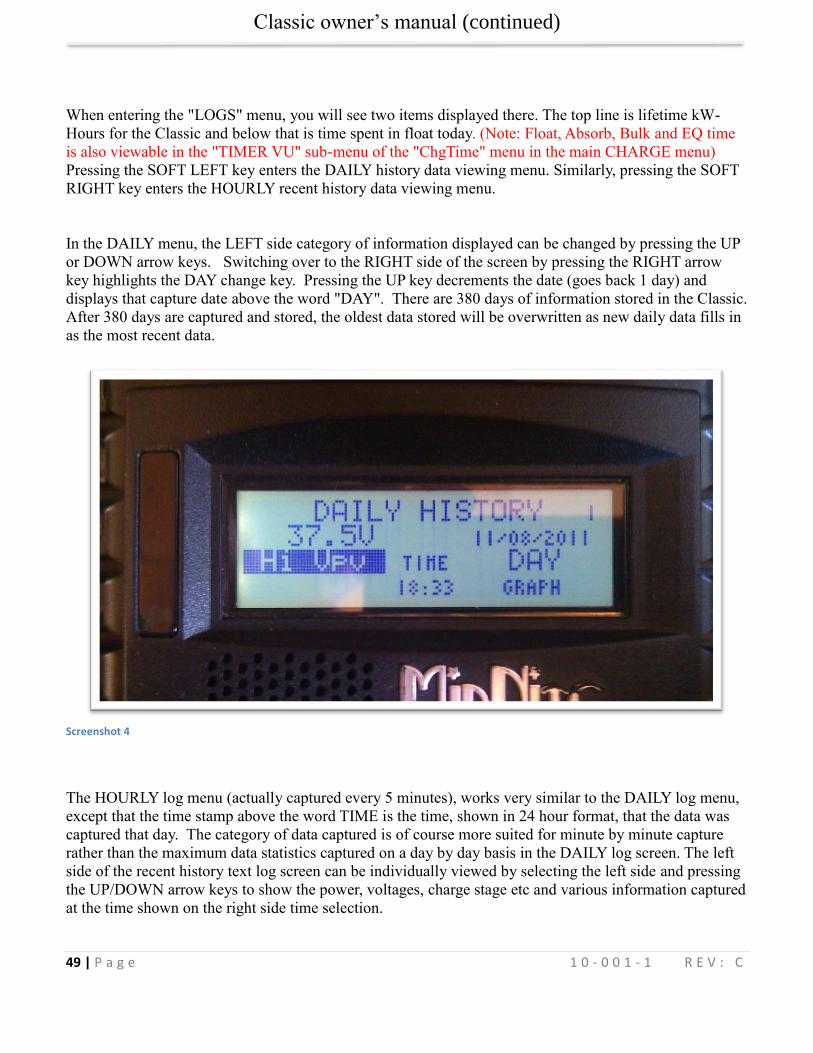
Classic owner’s manual (continued)
49 | P a g e 1 0 - 0 0 1 - 1 R E V : C
When entering the "LOGS" menu, you will see two items displayed there. The top line is lifetime kW-
Hours for the Classic and below that is time spent in float today. (Note: Float, Absorb, Bulk and EQ time
is also viewable in the "TIMER VU" sub-menu of the "ChgTime" menu in the main CHARGE menu)
Pressing the SOFT LEFT key enters the DAILY history data viewing menu. Similarly, pressing the SOFT
RIGHT key enters the HOURLY recent history data viewing menu.
In the DAILY menu, the LEFT side category of information displayed can be changed by pressing the UP
or DOWN arrow keys. Switching over to the RIGHT side of the screen by pressing the RIGHT arrow
key highlights the DAY change key. Pressing the UP key decrements the date (goes back 1 day) and
displays that capture date above the word "DAY". There are 380 days of information stored in the Classic.
After 380 days are captured and stored, the oldest data stored will be overwritten as new daily data fills in
as the most recent data.
Screenshot 4
The HOURLY log menu (actually captured every 5 minutes), works very similar to the DAILY log menu,
except that the time stamp above the word TIME is the time, shown in 24 hour format, that the data was
captured that day. The category of data captured is of course more suited for minute by minute capture
rather than the maximum data statistics captured on a day by day basis in the DAILY log screen. The left
side of the recent history text log screen can be individually viewed by selecting the left side and pressing
the UP/DOWN arrow keys to show the power, voltages, charge stage etc and various information captured
at the time shown on the right side time selection.
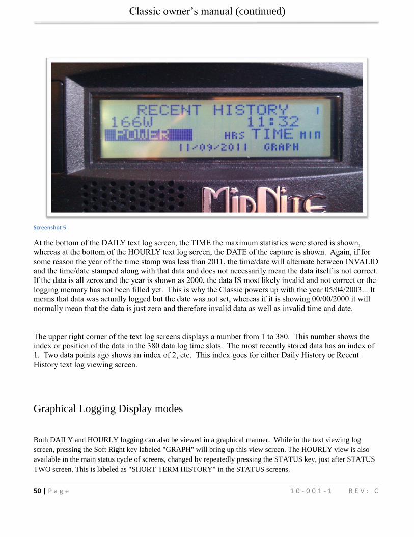
Classic owner’s manual (continued)
50 | P a g e 1 0 - 0 0 1 - 1 R E V : C
Screenshot 5
At the bottom of the DAILY text log screen, the TIME the maximum statistics were stored is shown,
whereas at the bottom of the HOURLY text log screen, the DATE of the capture is shown. Again, if for
some reason the year of the time stamp was less than 2011, the time/date will alternate between INVALID
and the time/date stamped along with that data and does not necessarily mean the data itself is not correct.
If the data is all zeros and the year is shown as 2000, the data IS most likely invalid and not correct or the
logging memory has not been filled yet. This is why the Classic powers up with the year 05/04/2003... It
means that data was actually logged but the date was not set, whereas if it is showing 00/00/2000 it will
normally mean that the data is just zero and therefore invalid data as well as invalid time and date.
The upper right corner of the text log screens displays a number from 1 to 380. This number shows the
index or position of the data in the 380 data log time slots. The most recently stored data has an index of
1. Two data points ago shows an index of 2, etc. This index goes for either Daily History or Recent
History text log viewing screen.
Graphical Logging Display modes
Both DAILY and HOURLY logging can also be viewed in a graphical manner. While in the text viewing log
screen, pressing the Soft Right key labeled "GRAPH" will bring up this view screen. The HOURLY view is also
available in the main status cycle of screens, changed by repeatedly pressing the STATUS key, just after STATUS
TWO screen. This is labeled as "SHORT TERM HISTORY" in the STATUS screens.
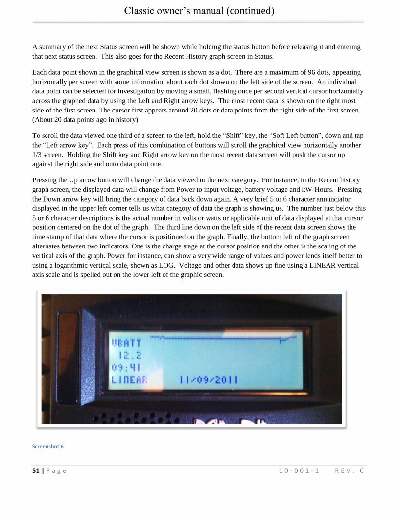
Classic owner’s manual (continued)
51 | P a g e 1 0 - 0 0 1 - 1 R E V : C
A summary of the next Status screen will be shown while holding the status button before releasing it and entering
that next status screen. This also goes for the Recent History graph screen in Status.
Each data point shown in the graphical view screen is shown as a dot. There are a maximum of 96 dots, appearing
horizontally per screen with some information about each dot shown on the left side of the screen. An individual
data point can be selected for investigation by moving a small, flashing once per second vertical cursor horizontally
across the graphed data by using the Left and Right arrow keys. The most recent data is shown on the right most
side of the first screen. The cursor first appears around 20 dots or data points from the right side of the first screen.
(About 20 data points ago in history)
To scroll the data viewed one third of a screen to the left, hold the “Shift” key, the “Soft Left button”, down and tap
the “Left arrow key”. Each press of this combination of buttons will scroll the graphical view horizontally another
1/3 screen. Holding the Shift key and Right arrow key on the most recent data screen will push the cursor up
against the right side and onto data point one.
Pressing the Up arrow button will change the data viewed to the next category. For instance, in the Recent history
graph screen, the displayed data will change from Power to input voltage, battery voltage and kW-Hours. Pressing
the Down arrow key will bring the category of data back down again. A very brief 5 or 6 character annunciator
displayed in the upper left corner tells us what category of data the graph is showing us. The number just below this
5 or 6 character descriptions is the actual number in volts or watts or applicable unit of data displayed at that cursor
position centered on the dot of the graph. The third line down on the left side of the recent data screen shows the
time stamp of that data where the cursor is positioned on the graph. Finally, the bottom left of the graph screen
alternates between two indicators. One is the charge stage at the cursor position and the other is the scaling of the
vertical axis of the graph. Power for instance, can show a very wide range of values and power lends itself better to
using a logarithmic vertical scale, shown as LOG. Voltage and other data shows up fine using a LINEAR vertical
axis scale and is spelled out on the lower left of the graphic screen.
Screenshot 6
Classic owner’s manual (continued)
52 | P a g e 1 0 - 0 0 1 - 1 R E V : C
The Date of the particular selected cursor positioned data point is shown on the bottom middle of the graphic
screen. Moving the cursor left or right using the Left and Right arrow keys, selects the next data points to the left or
to the right of the present cursor position.
The flashing cursor is short and may be hard to detect at first so you may have to look for it. The cursor aligns and
centers itself right on the dot itself that is selected.
The bottom date or time displayed may tend to obscure the data line graphed behind it. The time/date and the graph
data will be mixed together about a second after the date/time is drawn on the bottom of that graph log screen. If,
for some reason, the graphic log screen display shows bogus data or dots that look like they should not be shown,
simply press the Enter button and the screen will be quickly erased and re-drawn without the extra lines or dots.
There may or may not be any valid data past a certain point to the left if the unit is fairly new. The data shown in
unused spots may be zero, or it may be off the screen and not viewable. As time goes on and new data is acquired,
those unused data points will start to appear and be valid. Of course, the Daily history will take many days to fill in,
where the Recent hourly (minutes really) data will fill in after a few hours or maybe a day or two depending on how
long the Classic is on and running for that day. Remember, the Classic does not normally log data while it is in
“Resting” mode.
Dealer Information Screen
For dealers’ convenience the Classic has a display screen that can be modified to publicize the dealers’
business information. This is helpful because the customer will know who to contact in case they want to
report any problems regarding the product. This will also help to promote retailers’ accessories that are
compatible with the Classic. This screen is capable of 20 characters per row and four rows, for a total of
80 modifiable characters.
To modify this display screen, follow these steps:
Press main menu
Scroll to MISC and select it
On the following screen, select MNGP and press enter
On this screen select LOAD DEFAULTS press enter
On the password select 365 and press enter
Using the up and down keys will allow you to change the alphabet characters
Now scroll left and right to go to the next character block
Do this until your desired message is complete
Press enter to save on the classic memory
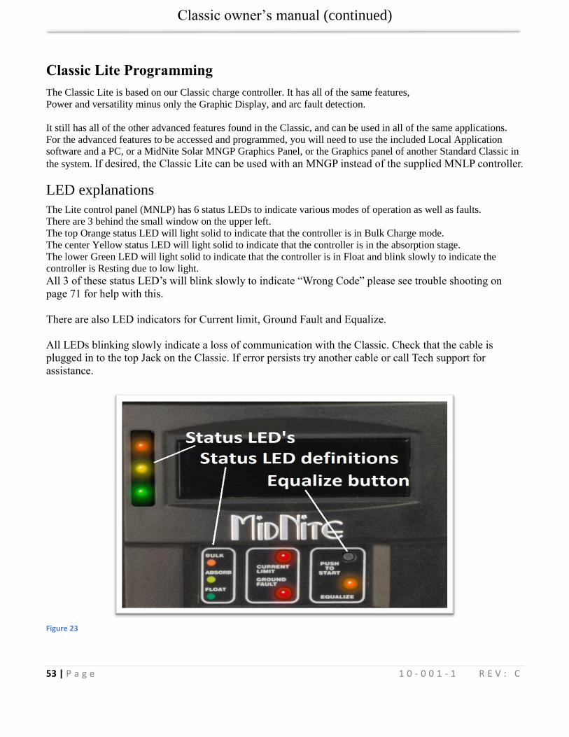
Classic owner’s manual (continued)
53 | P a g e 1 0 - 0 0 1 - 1 R E V : C
Classic Lite Programming
The Classic Lite is based on our Classic charge controller. It has all of the same features,
Power and versatility minus only the Graphic Display, and arc fault detection.
It still has all of the other advanced features found in the Classic, and can be used in all of the same applications.
For the advanced features to be accessed and programmed, you will need to use the included Local Application
software and a PC, or a MidNite Solar MNGP Graphics Panel, or the Graphics panel of another Standard Classic in
the system. If desired, the Classic Lite can be used with an MNGP instead of the supplied MNLP controller.
LED explanations
The Lite control panel (MNLP) has 6 status LEDs to indicate various modes of operation as well as faults.
There are 3 behind the small window on the upper left.
The top Orange status LED will light solid to indicate that the controller is in Bulk Charge mode.
The center Yellow status LED will light solid to indicate that the controller is in the absorption stage.
The lower Green LED will light solid to indicate that the controller is in Float and blink slowly to indicate the
controller is Resting due to low light.
All 3 of these status LED’s will blink slowly to indicate “Wrong Code” please see trouble shooting on
page 71 for help with this.
There are also LED indicators for Current limit, Ground Fault and Equalize.
All LEDs blinking slowly indicate a loss of communication with the Classic. Check that the cable is
plugged in to the top Jack on the Classic. If error persists try another cable or call Tech support for
assistance.
Figure 23
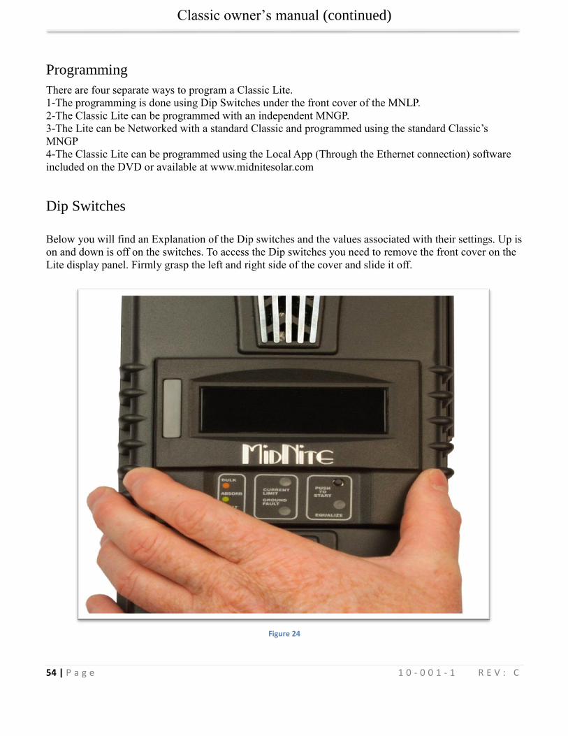
Classic owner’s manual (continued)
54 | P a g e 1 0 - 0 0 1 - 1 R E V : C
Programming
There are four separate ways to program a Classic Lite.
1-The programming is done using Dip Switches under the front cover of the MNLP.
2-The Classic Lite can be programmed with an independent MNGP.
3-The Lite can be Networked with a standard Classic and programmed using the standard Classic’s
MNGP
4-The Classic Lite can be programmed using the Local App (Through the Ethernet connection) software
included on the DVD or available at www.midnitesolar.com
Dip Switches
Below you will find an Explanation of the Dip switches and the values associated with their settings. Up is
on and down is off on the switches. To access the Dip switches you need to remove the front cover on the
Lite display panel. Firmly grasp the left and right side of the cover and slide it off.
Figure 24
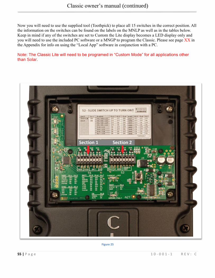
Classic owner’s manual (continued)
55 | P a g e 1 0 - 0 0 1 - 1 R E V : C
Now you will need to use the supplied tool (Toothpick) to place all 15 switches in the correct position. All
the information on the switches can be found on the labels on the MNLP as well as in the tables below.
Keep in mind if any of the switches are set to Custom the Lite display becomes a LED display only and
you will need to use the included PC software or a MNGP to program the Classic. Please see page XX in
the Appendix for info on using the “Local App” software in conjunction with a PC.
Note: The Classic Lite will need to be programed in “Custom Mode” for all applications other than Solar.
Figure 25
Classic owner’s manual (continued)
56 | P a g e 1 0 - 0 0 1 - 1 R E V : C
Section 1 Switch settings explained
Mode: Switches 1 and 2 (Section 1)
On Section 1, the first 2 Switches are used to select which Solar Mode will be used.
For “Solar” Mode: set switches 1 and 2 to OFF . This is the optimum setting for virtually all solar installations.
For “Legacy “ Mode: Set Switch 1 to OFF and Switch 2 to On.
Legacy Mode can be used in cases where the Open Circuit Voltage is close to the battery voltage. For example, a 22
volt open circuit array and a 12 volt battery. Or where there are mixed sizes of panels in an array. (Solar Salad)
When switch 1, 2, 3, and 4 are set to ON, the Lite is in “Custom Programming mode” and can be programmed using
any of the other 3 methods.
Custom set up will be required for Wind, Hydro, Fuel Cell applications as well as setting up the Aux. output
controls and for Battery voltages of 36, 60, and 72 (84, 96, 108, and 120 volt batteries for KS model)
System Voltage: Switches 3 and 4 (Section 1)
On Section 1, set Switches 3 and 4 to the appropriate positions (Found in the Chart) corresponding to your system's
battery voltage. 12, 24, and 48 volt systems are included in this menu. 36 and 72 volt battery set up can be
accomplished using the Custom set up method. (84, 96, 108, and 120 volt batteries for KS model)
Battery Type: Switches 5, 6, 7 (Section 1)
Switches 5, 6, and 7 allow you to select from 7 different battery types and charging profiles. These profiles can be
found in the 2 charts on the following pages. These should cover most common applications. If slightly different
voltages are desired, this can be done using Custom Mode and programming methods 2, 3, or 4.
Auto Equalize: Switch 8 (Section 1)
Switch 8 is used to select Automatic equalization.
In the OFF position, a manual equalization cycle, if desired, is selected by pressing the “Equalize”
button on the MNLP for 3 seconds. To Cancel Equalize, Press Equalize button for 3 seconds.
With Switch 8 in the ON position, the Lite will attempt to equalize the batteries automatically.
The equalize interval is dependent upon the battery type selected. Please refer to:
“Dip switch battery settings for 12, 24, or 48 volt batteries” for specific information on this function.
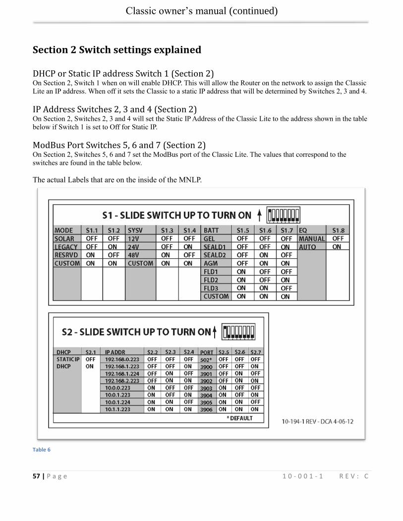
Classic owner’s manual (continued)
57 | P a g e 1 0 - 0 0 1 - 1 R E V : C
Section 2 Switch settings explained
DHCP or Static IP address Switch 1 (Section 2) On Section 2, Switch 1 when on will enable DHCP. This will allow the Router on the network to assign the Classic
Lite an IP address. When off it sets the Classic to a static IP address that will be determined by Switches 2, 3 and 4.
IP Address Switches 2, 3 and 4 (Section 2) On Section 2, Switches 2, 3 and 4 will set the Static IP Address of the Classic Lite to the address shown in the table
below if Switch 1 is set to Off for Static IP.
ModBus Port Switches 5, 6 and 7 (Section 2) On Section 2, Switches 5, 6 and 7 set the ModBus port of the Classic Lite. The values that correspond to the
switches are found in the table below.
The actual Labels that are on the inside of the MNLP.
Table 6
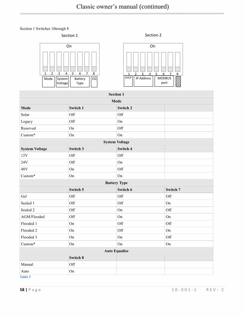
Classic owner’s manual (continued)
58 | P a g e 1 0 - 0 0 1 - 1 R E V : C
Section 1 Switches 1through 8
Section 1
Mode
Mode Switch 1 Switch 2
Solar Off Off
Legacy Off On
Reserved On Off
Custom* On On
System Voltage
System Voltage Switch 3 Switch 4
12V Off Off
24V Off On
48V On Off
Custom* On On
Battery Type
Switch 5 Switch 6 Switch 7
Gel Off Off Off
Sealed 1 Off Off On
Sealed 2 Off On Off
AGM/Flooded Off On On
Flooded 1 On Off Off
Flooded 2 On Off On
Flooded 3 On On Off
Custom* On On On
Auto Equalize
Switch 8
Manual Off
Auto On
Table 7
Section 1 Section 2
Mode System Voltage
Battery Type
EQ DHCP IP Address
MODBUS
port
1 2 3 4 5 6 7 8
On
1 2 3 4 5 6 7 8
On
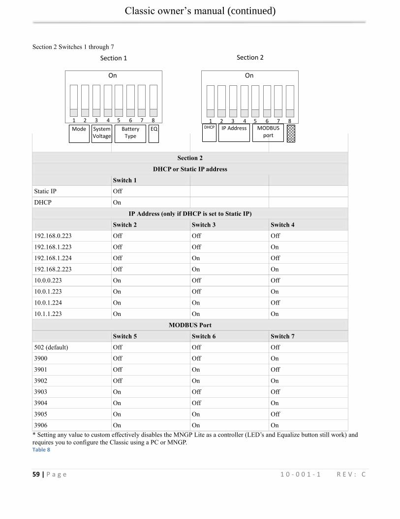
Classic owner’s manual (continued)
59 | P a g e 1 0 - 0 0 1 - 1 R E V : C
Section 2 Switches 1 through 7
Section 2
DHCP or Static IP address
Switch 1
Static IP Off
DHCP On
IP Address (only if DHCP is set to Static IP)
Switch 2 Switch 3 Switch 4
192.168.0.223 Off Off Off
192.168.1.223 Off Off On
192.168.1.224 Off On Off
192.168.2.223 Off On On
10.0.0.223 On Off Off
10.0.1.223 On Off On
10.0.1.224 On On Off
10.1.1.223 On On On
MODBUS Port
Switch 5 Switch 6 Switch 7
502 (default) Off Off Off
3900 Off Off On
3901 Off On Off
3902 Off On On
3903 On Off Off
3904 On Off On
3905 On On Off
3906 On On On
* Setting any value to custom effectively disables the MNGP Lite as a controller (LED’s and Equalize button still work) and
requires you to configure the Classic using a PC or MNGP. Table 8
Section 1 Section 2
Mode System Voltage
Battery Type
EQ DHCP IP Address
MODBUS
port
1 2 3 4 5 6 7 8
On
1 2 3 4 5 6 7 8
On
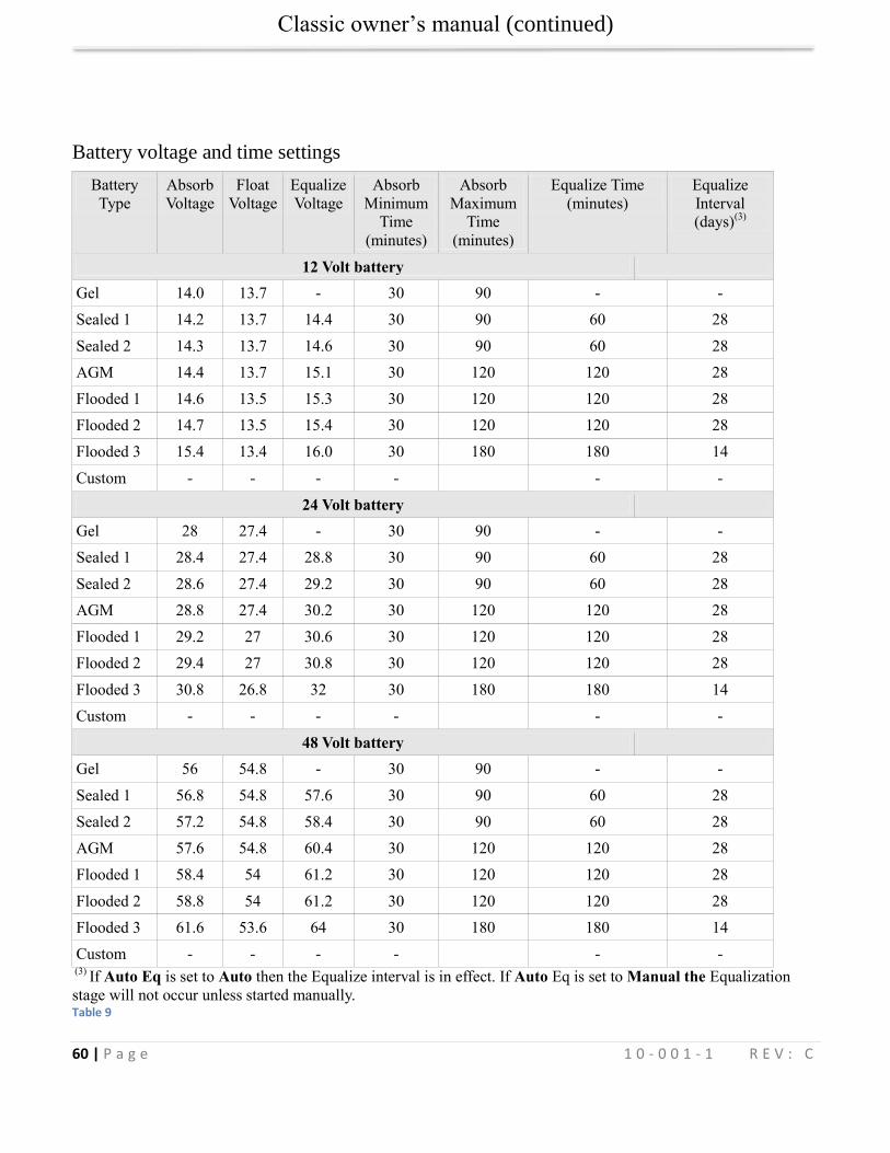
Classic owner’s manual (continued)
60 | P a g e 1 0 - 0 0 1 - 1 R E V : C
Battery voltage and time settings
Battery
Type
Absorb
Voltage
Float
Voltage
Equalize
Voltage
Absorb
Minimum
Time
(minutes)
Absorb
Maximum
Time
(minutes)
Equalize Time
(minutes)
Equalize
Interval
(days)(3)
12 Volt battery
Gel 14.0 13.7 - 30 90 - -
Sealed 1 14.2 13.7 14.4 30 90 60 28
Sealed 2 14.3 13.7 14.6 30 90 60 28
AGM 14.4 13.7 15.1 30 120 120 28
Flooded 1 14.6 13.5 15.3 30 120 120 28
Flooded 2 14.7 13.5 15.4 30 120 120 28
Flooded 3 15.4 13.4 16.0 30 180 180 14
Custom - - - - - -
24 Volt battery
Gel 28 27.4 - 30 90 - -
Sealed 1 28.4 27.4 28.8 30 90 60 28
Sealed 2 28.6 27.4 29.2 30 90 60 28
AGM 28.8 27.4 30.2 30 120 120 28
Flooded 1 29.2 27 30.6 30 120 120 28
Flooded 2 29.4 27 30.8 30 120 120 28
Flooded 3 30.8 26.8 32 30 180 180 14
Custom - - - - - -
48 Volt battery
Gel 56 54.8 - 30 90 - -
Sealed 1 56.8 54.8 57.6 30 90 60 28
Sealed 2 57.2 54.8 58.4 30 90 60 28
AGM 57.6 54.8 60.4 30 120 120 28
Flooded 1 58.4 54 61.2 30 120 120 28
Flooded 2 58.8 54 61.2 30 120 120 28
Flooded 3 61.6 53.6 64 30 180 180 14
Custom - - - - - - (3)
If Auto Eq is set to Auto then the Equalize interval is in effect. If Auto Eq is set to Manual the Equalization
stage will not occur unless started manually. Table 9
Classic owner’s manual (continued)
61 | P a g e 1 0 - 0 0 1 - 1 R E V : C
Using MNGP Remote to program a Classic Lite
The Classic Lite can be programmed using an MNGP remote. This is an easy way to get into and program not only
the basic functions, but the advanced features as well. In Dip Switch Section 1set DIP Switches 1, 2, 3, and 4 to ON.
This will tell the Classic Lite's MNLP display to allow custom programming, Next, remove the plug from the back
of the MNLP and plug it into the MNGP. Now, you basically have a Standard Classic. The programming for this is
found in the Standard Classic Manual. (Included on the DVD you got with your Lite) Once programmed in this
way, the MNGP can be removed, and the MNLP replaced. All functions, and voltages programed into the Classic
will now be retained in permanent memory.
Programming the Lite with a Networked Standard Classic
The third method of programming is to use a Standard Classic in the system to program the Lite in a simple
“Follow-Me” network. In Dip Switch Section 1set DIP Switches 1, 2, 3, and 4 to ON. This will tell the Lite’s MNLP
display to allow custom programming. You will need to use the MNGP from the standard Classic to set the Address
and Follow-Me parameters. See the Follow-Me section for full details.
Programming the Lite with the Local App
You can use the Local Application software that was included with the Lite to program it as well. You will
need the serial number of the Classic to unlock the 2 way functionality of the Local App. Please see the
Local App instructions for more details.
Clearing Faults
If either the Ground Fault or Current Limit fault light is lit, then the equalize button can be tapped to clear
these faults. If the fault condition has not been removed, however, then the light will re-illuminate
indicating that a fault condition is still present.
Notes on the Lite
If anything is set to Custom, then the MNGP lite will not send any programming data to the Classic. So a
Custom setting effectively disables MNGP Lite Control over the Classic requiring the user to use a PC or
MNGP to configure the Classic.
Note: The Custom setting still allows full function of the LED’s and the EQ button
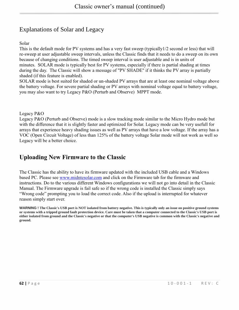
Classic owner’s manual (continued)
62 | P a g e 1 0 - 0 0 1 - 1 R E V : C
Explanations of Solar and Legacy
Solar
This is the default mode for PV systems and has a very fast sweep (typically1/2 second or less) that will
re-sweep at user adjustable sweep intervals, unless the Classic finds that it needs to do a sweep on its own
because of changing conditions. The timed sweep interval is user adjustable and is in units of
minutes. SOLAR mode is typically best for PV systems, especially if there is partial shading at times
during the day. The Classic will show a message of "PV SHADE" if it thinks the PV array is partially
shaded (if this feature is enabled).
SOLAR mode is best suited for shaded or un-shaded PV arrays that are at least one nominal voltage above
the battery voltage. For severe partial shading or PV arrays with nominal voltage equal to battery voltage,
you may also want to try Legacy P&O (Perturb and Observe) MPPT mode.
Legacy P&O
Legacy P&O (Perturb and Observe) mode is a slow tracking mode similar to the Micro Hydro mode but
with the difference that it is slightly faster and optimized for Solar. Legacy mode can be very usefull for
arrays that experience heavy shading issues as well as PV arrays that have a low voltage. If the array has a
VOC (Open Circuit Voltage) of less than 125% of the battery voltage Solar mode will not work as well so
Legacy will be a better choice.
Uploading New Firmware to the Classic
The Classic has the ability to have its firmware updated with the included USB cable and a Windows
based PC. Please see www.midntesolar.com and click on the Firmware tab for the firmware and
instructions. Do to the various different Windows configurations we will not go into detail in the Classic
Manual. The Firmware upgrade is fail safe so if the wrong code is installed the Classic simply says
“Wrong code” prompting you to load the correct code. Also if the upload is interrupted for whatever
reason simply start over. WARNING ! The Classic's USB port is NOT isolated from battery negative. This is typically only an issue on positive ground systems
or systems with a tripped ground fault protection device. Care must be taken that a computer connected to the Classic's USB port is
either isolated from ground and the Classic's negative or that the computer's USB negative is common with the Classic's negative and
ground.
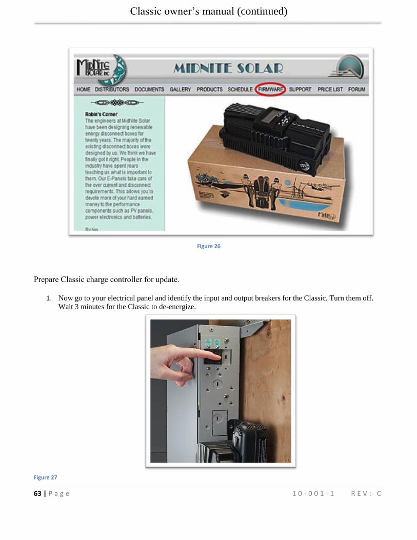
Classic owner’s manual (continued)
63 | P a g e 1 0 - 0 0 1 - 1 R E V : C
Figure 26
Prepare Classic charge controller for update.
1. Now go to your electrical panel and identify the input and output breakers for the Classic. Turn them off.
Wait 3 minutes for the Classic to de-energize.
Figure 27
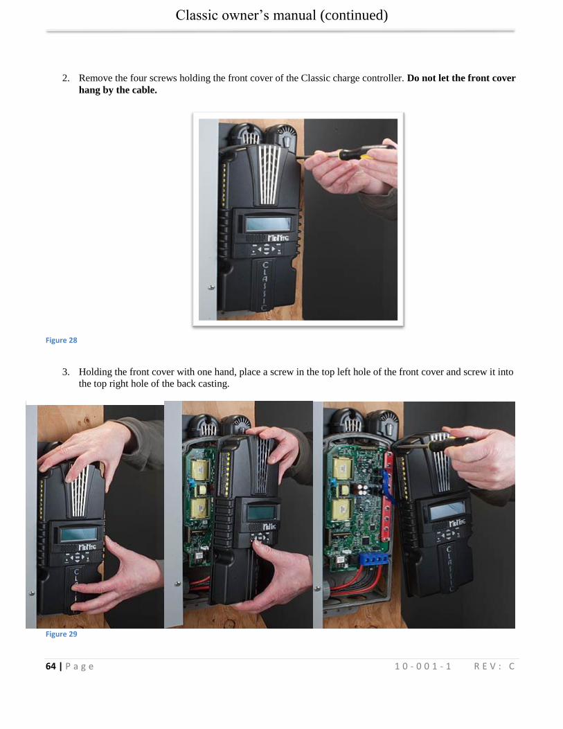
Classic owner’s manual (continued)
64 | P a g e 1 0 - 0 0 1 - 1 R E V : C
2. Remove the four screws holding the front cover of the Classic charge controller. Do not let the front cover
hang by the cable.
Figure 28
3. Holding the front cover with one hand, place a screw in the top left hole of the front cover and screw it into
the top right hole of the back casting.
Figure 29
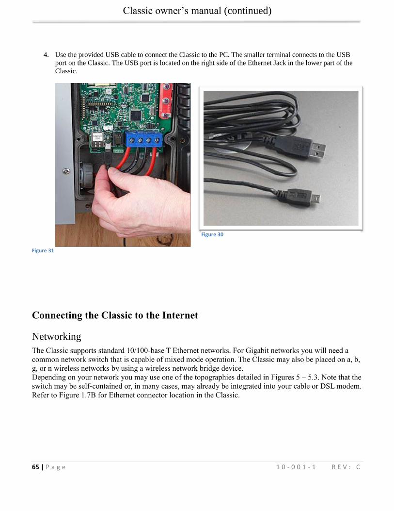
Classic owner’s manual (continued)
65 | P a g e 1 0 - 0 0 1 - 1 R E V : C
4. Use the provided USB cable to connect the Classic to the PC. The smaller terminal connects to the USB
port on the Classic. The USB port is located on the right side of the Ethernet Jack in the lower part of the
Classic.
Figure 31
Connecting the Classic to the Internet
Networking
The Classic supports standard 10/100-base T Ethernet networks. For Gigabit networks you will need a
common network switch that is capable of mixed mode operation. The Classic may also be placed on a, b,
g, or n wireless networks by using a wireless network bridge device.
Depending on your network you may use one of the topographies detailed in Figures 5 – 5.3. Note that the
switch may be self-contained or, in many cases, may already be integrated into your cable or DSL modem.
Refer to Figure 1.7B for Ethernet connector location in the Classic.
Figure 30
Classic owner’s manual (continued)
66 | P a g e 1 0 - 0 0 1 - 1 R E V : C
4-Port Switch / Router
Example 1 Local network through switch. In some cases you may be able to connect Classic directly to your PC; however, this is not a recommended topography.
Wireless Router/ Access Point
Wireless Bridge
Wireless Router/ Access Point
Wireless enabled computer
Example 3 Local wireless network
Example 2 Local network through wireless bridge.
Classic owner’s manual (continued)
67 | P a g e 1 0 - 0 0 1 - 1 R E V : C
There are many different configurations possible when it comes to networking that are beyond the scope
of this manual. The basic ones in the above figures should help get you going.
Network Setup Through the MNGP
The Classic’s Ethernet capabilities may be configured using the Network menu on the MNGP. From the
main menu select “NET”.
There are three screens that configure network settings. Table TBD decodes the descriptions from the
MNGP’s small screen.
MNGP Long-hand Description
Mode IP address configuration mode: DHCP/Static
The Classic supports both static and dynamically (DHCP) allocated IP addresses. If you are unsure which to choose try DHCP first. If you have trouble move to the troubleshooting section.
IP IP Address The Network address of the Classic
SN Subnet The Subnet or address class specifier
GW Gateway Address The address of the network’s gateway device
D1 Primary DNS Address Primary Address lookup device
D2 Secondary DNS Address Secondary Address lookup device (optional)
Web Access
- Enables or disables the Classic’s online web service feature
MA MAC Address The hardware or Ethernet address of the Classic
DI Device ID The unique MidNite Solar address of the Classic
Table 10
DHCP
The Classic supports Dynamic Host Configuration Protocol (DHCP) in which all networking settings are
derived from a DHCP-enabled router. This is the simplest configuration method and recommended unless
you explicitly need a statically allocated IP address for your Classic. In this mode all other settings are
automatically configured and are read only (informational) with the exception of the Web Access feature.
Press Main Menu
Scroll to NET menu and press the Enter button
Highlight and select DCHP
Wireless enabled computer
Wireless Router/ Access Point
Wireless Bridge
Example 4 Local wireless network through wireless bridge
Classic owner’s manual (continued)
68 | P a g e 1 0 - 0 0 1 - 1 R E V : C
Please note that the Classic’s DHCP protocol implementation usually takes a few seconds up to a minute
to update the network settings. If the network settings do not update within a minute, please consult the
troubleshooting section.
Static IP
The Classic supports static IP address allocation. In this mode you can assign the Classic a specific IP
address. This lets you set up things like port forwarding from your router or for networks with static IP
allocations.
Press Main Menu
Scroll to NET menu and press the Enter button
Highlight and select STATIC
Using the left and right keys, navigate to the settings to change and use the up and down arrows to adjust the desired fields.
Press the COMMIT softkey at any time to commit the settings to the Classic’s Flash memory.
Please note that static settings span two menu screens. You may use the soft keys to navigate between the
two menus. Pressing the ENTER key in either menu saves all settings to Flash memory.
For convenience when you manually set the device’s IP address the Gateway and Primary DNS addresses
follow the change. See the following sections for details on each of these fields.
IP Address
This is the local network address of your Classic. It usually takes the form “192.169.0/1.x” or “10.0.0.x”
depending on your networking equipment. You must be careful when selecting this address. If it does not
match your network subnet then the classic will not be able to communicate with the network. If it is the
same as another device on the network then collisions will occur causing both devices to act erratically.
Check your router settings or ask your network administrator which local address to use. Also refer to the
troubleshooting section for tips.
Subnet
This refers to the class of local network you are using. This depends on your network hardware but most
users should use “255.255.255.0” for this field.
Gateway
This is the address of your router or modem – the device which is connected directly to the Internet
proper. It will usually take the form 192.168.0/1.1 or 10.0.0.1 depending on your network configuration
and hardware. Check your router settings or ask your network administrator which local address to use.
Also refer to the troubleshooting section for tips.
DNS 1 & 2
The DNS is the means by which human-readable internet addresses are resolved to actual IP addresses on
the network. These values can usually be set identically to the gateway address depending on your
network hardware. If your ISP provides you with specific DNS servers then use those addresses in these
fields instead.
Example 1: Your gateway is a DSL modem with address 192.168.1.1. If your ISP has not given you
explicit DNS servers to use then set the D1 field to 192.168.1.1. D2 can be ignored.
Example 2: Your gateway is a cable modem with address 10.0.0.1. Your ISP has specified primary and
secondary DNS server addresses of 11.22.33.44 and 11.22.33.55, respectively. Set the D1 address to
Classic owner’s manual (continued)
69 | P a g e 1 0 - 0 0 1 - 1 R E V : C
11.22.33.44 and the D2 address to 11.22.33.55.
Web Access
MidNite Solar will be offering a free web service with which you can access your Classic from a web
page from anywhere in the world simply by pointing your favorite web browser to
http://www.mymidnite.com
See the web section further on for instructions on how to create an account and use the web-based system.
All communications between the Classic and MidNite Solar’s server are encrypted using a strong session-
based algorithm. To respect your privacy, however, it is required that you manually enable this feature if
you’d like to use it.
In order to enable the web access feature:
Press Main Menu
Scroll to NET menu and press the Enter button
using the soft keys, navigate to the ADVANCED menu (NET→NEXT→ADVANCED)
The Web Access option should be highlighted.
Use the up/down keys to now enable or disable the feature.
Note that the Web Access selection indicates the current setting of the feature: i.e. ENABLED means the
feature is currently in operation.
Note also that you will need the values MA and DI handy in order to create an account on the MidNite
Solar web site. This unique number pair identifies your particular classic to our server and helps to prevent
malicious users from trying to access your Classic. The DI or Device Id is different than your Unit’s Serial
Number.
Local Network
Note that your classic identifies itself by name to DHCP-enabled routers as “Classic”. There is facility to
change the name of a given classic via the local and web-based interfaces as well as using third-party
MODBUS software packages.
Advanced
The Classic advertises its address every 10 seconds using the UDP protocol on port (TBD). Advanced
users and programmers may use this feature to identify Classics on their network.
Positive Ground systems
When installing the Classic in a positive ground systems there are a few extra steps that need to be taken.
The Ground fault jumper needs to be removed, and ground fault needs to be disabled in the menu. Refer to
page Disabling GFP on page 22 for instructions on doing this.
The overcurrent protection needs to be done a little different as well. The input and output breakers need
to be double poles. Battery negative and positive conductor both need to be protected. Refer to Classic
Breaker Sizing on Page 76.
IMPORTANT: Do not connect both, positive battery and positive PV input to ground. One or the
Classic owner’s manual (continued)
70 | P a g e 1 0 - 0 0 1 - 1 R E V : C
other positive (normally battery +) but not both otherwise the Classic input and output will be
shorted.
HyperVOC ™
HyperVOC is a unique feature the Classic has built in. HyperVOC refers to; when the DC Input Voltage
raises above the maximum operating voltage (150V, 200V, 250V, depending on the Classic model).
HyperVOC gives you the flexibility to go up to the maximum operating voltage PLUS the nominal battery
voltage. For example, the Classic 150 has an input voltage rating of 150 operating volts, if the Classic 150
is connected to a 48 volt battery bank, the HyperVOC voltage limit will be: 150V + 48V a total of 198
Volts that the Classic can withstand without breaking. When the Classic input voltage rises above 150
volts it will switch off (stop outputting power). As long as the Classic is in HyperVOC mode, the
microprocessor and all other functions like AUX will continue running. When the input voltage comes
back down below 150v (or the rated operating voltage of the Classic, depending on model) the Classic
will wake up and start charging again automatically. This could happen in a really cold morning with a
system that has a Voltage Open Circuit (VOC) close to the maximum operating input voltage.
Note 1. A HyperVOC message will be displayed on the bottom right side of the Status screen.
Note 2. Max nominal battery voltage to be added is 48v
HyperVOC can be useful in overcoming an industry shortcoming in charging 48 volt battery’s with
standard panels. For example let’s take a sample system with Solar World 165’s that have a VOC of
44.1vdc. The industry has limited us to 2 of these panels in series making it hard to charge a 48vdc battery
on hot summer days. With the Classic we designed in Hyper VOC to allow you to run 3 of these in series.
3 panels at 44.1vdc will give you a total VOC of 132.3vdc. When temperature compensated for cold
climates to 125% gives you 165vdc. This is above the maximum safe limits for most controllers but falls
well into the Hyper VOC range of the Classic. We do have to use Hyper VOC wisely though if we abuse it
the Controller will never wake up in colder weather.
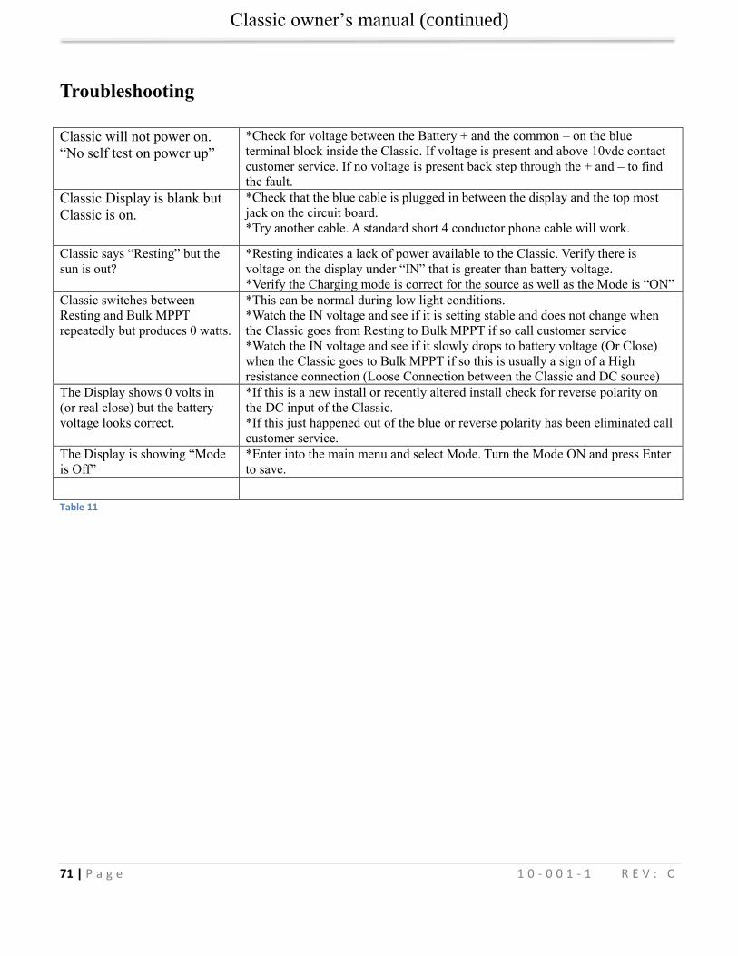
Classic owner’s manual (continued)
71 | P a g e 1 0 - 0 0 1 - 1 R E V : C
Troubleshooting
Classic will not power on.
“No self test on power up”
*Check for voltage between the Battery + and the common – on the blue
terminal block inside the Classic. If voltage is present and above 10vdc contact
customer service. If no voltage is present back step through the + and – to find
the fault. Classic Display is blank but
Classic is on.
*Check that the blue cable is plugged in between the display and the top most
jack on the circuit board.
*Try another cable. A standard short 4 conductor phone cable will work.
Classic says “Resting” but the
sun is out?
*Resting indicates a lack of power available to the Classic. Verify there is
voltage on the display under “IN” that is greater than battery voltage.
*Verify the Charging mode is correct for the source as well as the Mode is “ON”
Classic switches between
Resting and Bulk MPPT
repeatedly but produces 0 watts.
*This can be normal during low light conditions.
*Watch the IN voltage and see if it is setting stable and does not change when
the Classic goes from Resting to Bulk MPPT if so call customer service
*Watch the IN voltage and see if it slowly drops to battery voltage (Or Close)
when the Classic goes to Bulk MPPT if so this is usually a sign of a High
resistance connection (Loose Connection between the Classic and DC source)
The Display shows 0 volts in
(or real close) but the battery
voltage looks correct.
*If this is a new install or recently altered install check for reverse polarity on
the DC input of the Classic.
*If this just happened out of the blue or reverse polarity has been eliminated call
customer service.
The Display is showing “Mode
is Off”
*Enter into the main menu and select Mode. Turn the Mode ON and press Enter
to save.
Table 11
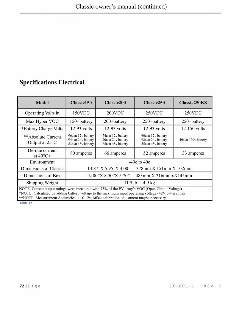
Classic owner’s manual (continued)
72 | P a g e 1 0 - 0 0 1 - 1 R E V : C
Specifications Electrical
Model Classic150 Classic200 Classic250 Classic250KS
Operating Volts in 150VDC 200VDC 250VDC 250VDC
Max Hyper VOC 150+battery 200+battery 250+battery 250+battery
*Battery Charge Volts 12-93 volts 12-93 volts 12-93 volts 12-150 volts
**Absolute Current
Output at 25°C
96a at 12v battery
94a at 24v battery
83a at 48v battery
74a at 12v battery
70a at 24v battery
65a at 48v battery
60a at 12v battery
62a at 24v battery
55a at 48v battery
40a at 120v battery
De-rate current
at 40°C+ 80 amperes 66 amperes 52 amperes 33 amperes
Environment -40c to 40c
Dimensions of Classic 14.87”X 5.95”X 4.00” 378mm X 151mm X 102mm
Dimensions of Box 19.00”X 8.50”X 5.70” 483mm X 216mm xX145mm
Shipping Weight 11.5 lb 4.9 kg
NOTE: Current output ratings were measured with 75% of the PV array’s VOC (Open Circuit Voltage)
*NOTE: Calculated by adding battery voltage to the maximum input operating voltage (48V battery max)
* **NOTE: Measurement Accuracies: +- 0.12v, offset calibration adjustment maybe necessary
Table 12
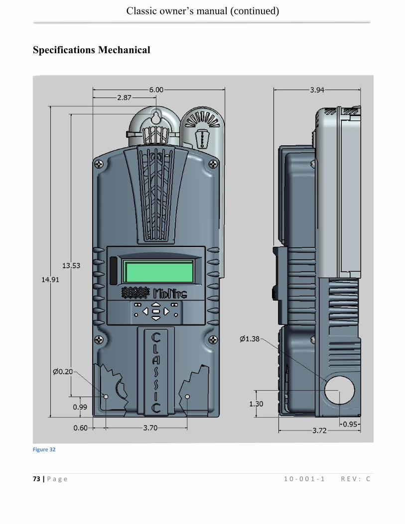
Classic owner’s manual (continued)
73 | P a g e 1 0 - 0 0 1 - 1 R E V : C
Specifications Mechanical
Figure 32
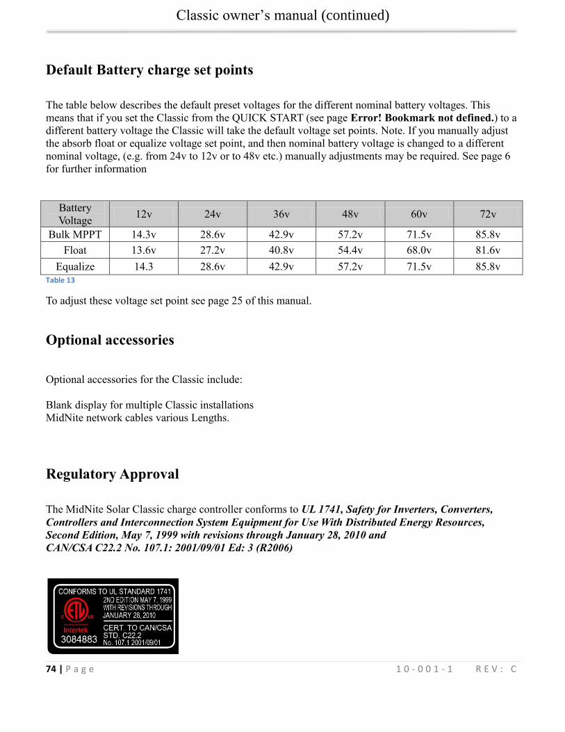
Classic owner’s manual (continued)
74 | P a g e 1 0 - 0 0 1 - 1 R E V : C
Default Battery charge set points
The table below describes the default preset voltages for the different nominal battery voltages. This
means that if you set the Classic from the QUICK START (see page Error! Bookmark not defined.) to a
different battery voltage the Classic will take the default voltage set points. Note. If you manually adjust
the absorb float or equalize voltage set point, and then nominal battery voltage is changed to a different
nominal voltage, (e.g. from 24v to 12v or to 48v etc.) manually adjustments may be required. See page 6
for further information
Battery
Voltage 12v 24v 36v 48v 60v 72v
Bulk MPPT 14.3v 28.6v 42.9v 57.2v 71.5v 85.8v
Float 13.6v 27.2v 40.8v 54.4v 68.0v 81.6v
Equalize 14.3 28.6v 42.9v 57.2v 71.5v 85.8v
Table 13
To adjust these voltage set point see page 25 of this manual.
Optional accessories
Optional accessories for the Classic include:
Blank display for multiple Classic installations
MidNite network cables various Lengths.
Regulatory Approval
The MidNite Solar Classic charge controller conforms to UL 1741, Safety for Inverters, Converters,
Controllers and Interconnection System Equipment for Use With Distributed Energy Resources,
Second Edition, May 7, 1999 with revisions through January 28, 2010 and
CAN/CSA C22.2 No. 107.1: 2001/09/01 Ed: 3 (R2006)

Classic owner’s manual (continued)
75 | P a g e 1 0 - 0 0 1 - 1 R E V : C
Warranty
MidNite Solar's Classic comes with a standard 5 year warranty we will repair or replace the Classic at no
charge to the consumer during this 5 year period
Appendix
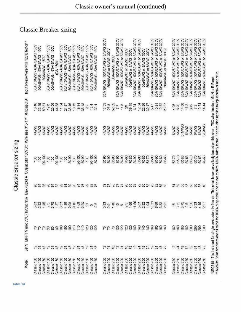
Classic owner’s manual (continued)
76 | P a g e 1 0 - 0 0 1 - 1 R E V : C
Classic Breaker sizing
Table 14
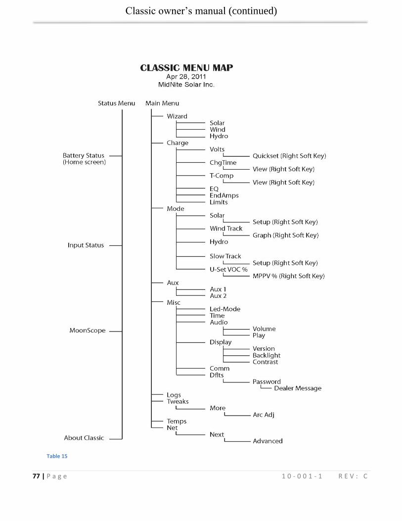
Classic owner’s manual (continued)
77 | P a g e 1 0 - 0 0 1 - 1 R E V : C
Table 15
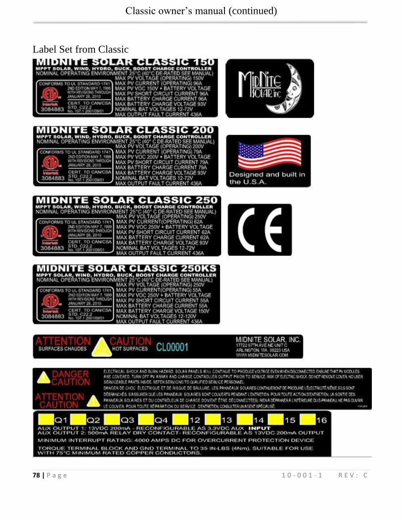
Classic owner’s manual (continued)
78 | P a g e 1 0 - 0 0 1 - 1 R E V : C
Label Set from Classic
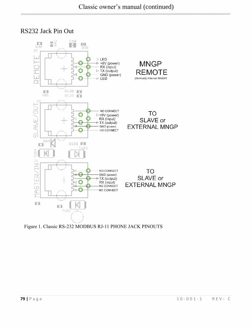
Classic owner’s manual (continued)
79 | P a g e 1 0 - 0 0 1 - 1 R E V : C
RS232 Jack Pin Out
Figure 1. Classic RS-232 MODBUS RJ-11 PHONE JACK PINOUTS