m m pakka wala hai - copy
TRANSCRIPT
8/8/2019 m m Pakka Wala Hai - Copy
http://slidepdf.com/reader/full/m-m-pakka-wala-hai-copy 1/13
Angular Measurement
Instruments for Angular Measurement
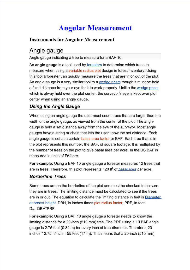
Angle gaugeAngle gauge indicating a tree to measure for a BAF 10
An angle gauge is a tool used by foresters to determine which trees to
measure when using a variable radius plot design in forest inventory. Using
this tool a forester can quickly measure the trees that are in or out of the plot.
An angle gauge is a very similar tool to a wedge prism though it must be held
a fixed distance from your eye for it to work properly. Unlike the wedge prism,
which is alway held over the plot center, the surveyor's eye is kept over plotcenter when using an angle gauge.
Using the Angle Gauge
When using an angle gauge the user must count trees that are larger than the
width of the angle gauge, as viewed from the center of the plot. The angle
gauge is held a set distance away from the eye of the surveyor. Most angle
gauges have a string or chain that lets the user know the set distance. Each
angle gauge is set at a certain basal area factor or BAF. Each tree that is in
the plot represents this number, the BAF, of square footage. It is multiplied by
the number of trees on the plot to give basal area per acre. In the US BAF is
measured in units of Ft2/acre.
For example: Using a BAF 10 angle gauge a forester measures 12 trees that
are in trees. Therefore, this plot represents 120 ft2 of basal area per acre.
Borderline Trees
Some trees are on the borderline of the plot and must be checked to be sure
they are in trees. The limiting distance must be calculated to see if the trees
are in or out. The equation to calculate the limiting distance in feet is Diameter
at breast height, DBH, in inches times plot radius factor , PRF, in feet.
Dlim=DBH*PRF
For example: Using a BAF 10 angle gauge a forester needs to know the
limiting distance for a 20-inch (510 mm) tree. The PRF using a 10 BAF angle
gauge is 2.75 feet (0.84 m) for every inch of tree diameter. Therefore, 20
inches * 2.75 ft/inch = 55 feet (17 m). This means that a 20-inch (510 mm)

8/8/2019 m m Pakka Wala Hai - Copy
http://slidepdf.com/reader/full/m-m-pakka-wala-hai-copy 2/13
tree must be over 55 feet (17 m) away from the center of the plot using a BAF
10 angle gauge to be out of the plot.
Sine bar
A sine bar is a tool used to measure angles in metalworking.
It consists of a hardened, precision ground body with two precision ground
cylinders fixed at the ends. The distance between the centers of the cylindersis precisely controlled, and the top of the bar is parallel to a line through the
centers of the two rollers. The dimension between the two rollers is chosen to
be a whole number (for ease of later calculations) and forms
the hypotenuse of a triangle when in use. The image shows a 10 inch and a
100 mm sine bar, however, in the U.S., 5 inch sine bars are the most
commonly used.
When a sine bar is placed on a level surface the top edge will be parallel to
that surface. If one roller is raised by a known distance, usually using gauge
blocks, then the top edge of the bar will be tilted by the same amount forming
an angle that may be calculated by the application of the sine rule.
The hypotenuse is a constant dimension — (100 mm or 10 inches in
the examples shown).
The height is obtained from the dimension between the bottom of one
roller and the table's surface.
The angle is calculated by using the sine rule. Some engineering andmetalworking reference books contain tables showing the dimension
required to obtain an angle from 0-90 degrees, incremented by 1 minute
intervals.
Angles may be measured or set with this tool.
8/8/2019 m m Pakka Wala Hai - Copy
http://slidepdf.com/reader/full/m-m-pakka-wala-hai-copy 3/13
Principle
Angles are measured using a sine bar with the help of gauge blocks and
a dial gauge or a spirit level. The aim of a measurement is to make the
surface on which the dial gauge or spirit level is placed horizontal. For example, to measure the angle of a wedge, the wedge is placed on a
horizontal table. The sine bar is placed over the inclined surface of the wedge.
At this position, the top surface of the sine bar is inclined the same amount as
the wedge. Using gauge blocks, the top surface is made horizontal. The sine
of the angle of inclination of the wedge is the ratio of the height of the gauge
blocks used and the distance between the centers of the cylinders.
Types
Sine centre
A special type of sine bar is sine centre which is used for conical objects
having male and female parts. It cannot measure the angle more than 45
degrees.
sine table
Sine table (or sine plate) is used to measure angles of large workpieces.
Compound sine tableIt is used to measure compound angles of large workpieces. In this case, two sine
tables are mounted one over the other at right angles. The tables can be twisted
to get the required alignment.
clinometer
An inclinometer or clinometer is an instrument for measuring angles
of slope (or tilt), elevation or inclination of an object with respect to gravity. It is
also known as a tilt meter , tilt indicator , slope alert , slope gauge, gradient
meter , gradiometer , level gauge, level meter , declinometer , and pitch & roll
indicator . Clinometers measure both inclines (positive slopes, as seen by an
observer looking upwards) and declines (negative slopes, as seen by an
observer looking downward).
In aircraft, the "ball" in turn coordinators or turn and bank indicators is
sometimes referred to as an inclinometer.

8/8/2019 m m Pakka Wala Hai - Copy
http://slidepdf.com/reader/full/m-m-pakka-wala-hai-copy 4/13
History
Early inclinometers include examples such as Well's inclinometer , the
essential parts of which are a flat side, or base, on which it stands, and ahollow disk just half filled with some heavy liquid. The glass face of the disk is
surrounded by a graduated scale that marks the angle at which the surface of
the liquid stands, with reference to the flat base. The line 0.—0. being parallel
to the base, when the liquid stands on that line, the flat side is horizontal; the
line 90.—90. being perpendicular to the base, when the liquid stands on that
line, the flat side is perpendicular or plumb. Intervening angles are marked,
and, with the aid of simple conversion tables, the instrument indicates the rate
of fall per set distance of horizontal measurement, and set distance of the
sloping line.
Accuracy
Clinometer designed to enable indirect firecapability with a Vickers machine
gun circa 1918
Certain highly sensitive electronic inclinometer sensors can achieve an output
resolution to 0.001 degrees - depending on the technology and angle range, it
may be limited to 0.01º. An inclinometer sensor's true or absolute accuracy
(which is the combined total error), however, is a combination of initial sets of
sensor zero offset and sensitivity, sensor linearity, hysteresis, repeatability,
and the temperature drifts of zero and sensitivity - electronic inclinometers
accuracy can typically range from .01º to ±2º depending on the sensor and
situation. Typically in room ambient conditions the accuracy is limited to the
sensor linearity specification.

8/8/2019 m m Pakka Wala Hai - Copy
http://slidepdf.com/reader/full/m-m-pakka-wala-hai-copy 5/13
The Well's clinometer
A simple clinometer
Sensor technology
Tilt sensors and inclinometers generate an artificial horizon and measure
angular tilt with respect to this horizon. They are used in cameras, aircraft
flight controls, automobile security systems, and speciality switches and are
also used for platform leveling, boom angle indication, indeed anywhere tilt
requires measuring.
Important specifications to consider when searching for tilt sensors and
inclinometers are the tilt angle range and number of axes (which are usually,
but not always, orthogonal). The tilt angle range is the range of desired linear
output.
Common sensor technologies for tilt sensors and inclinometers areaccelerometer, Liquid Capacitive, electrolytic, gas bubble in liquid, and
pendulum.
.Inclinometers are also used in civil engineering, for example to measure the
inclination of land to be built upon.
Some inclinometers provide an electronic interface based on CAN (Controller
Area Network). In addition, those inclinometers may support the
standardizedCANopen profile (CiA 410). In this case, these inclinometers are
compatible and partly interchangeable.
8/8/2019 m m Pakka Wala Hai - Copy
http://slidepdf.com/reader/full/m-m-pakka-wala-hai-copy 6/13
Uses
Inclinometers are used for:
Determining latitude using Polaris (in the Northern Hemisphere) or the
two stars of the constellation Crux (in the Southern Hemisphere).
Determining the angle of the Earth's magnetic field with respect to the
horizontal plane.
Showing a deviation from the true vertical or horizontal.
Surveying, to measure an angle of inclination or elevation.
Alerting an equipment operator that it may tip over.
Measuring angles of elevation, slope, or incline, e.g. of an
embankment. Measuring slight differences in slopes, particularly for geophysics.
Such inclinometers are, for instance, used for monitoring volcanoes, or for
measuring the depth and rate of landslide movement.
Measuring movements in walls or the ground in civil engineering
projects.
Determining the dip of beds or strata, or the slope of an embankment
or cutting; a kind of plumb level.
Some automotive safety systems. Indicating pitch and roll of vehicles, nautical craft, and aircraft. See turn
coordinator and slip indicator .
Monitoring the boom angle of cranes and material handlers.
Measuring the "look angle" of a satellite antenna towards a satellite.
Measuring the slope angle of a tape or chain during distance
measurement.
Measuring the height of a building, tree, or other feature using a
vertical angle and a distance (determined by taping or pacing),using trigonometry.
Measuring the angle of drilling in well logging.
Measuring the list of a ship in still water and the roll in rough water.
Measuring steepness of a ski slope.
Measuring the orientation of planes and lineations in rocks, in
combination with a compass, in structural geology.
Measuring Range of Motion in the joints of the body
Measuring the angles of elevation to, and ultimately computing thealtitudes of, many things otherwise inaccessible for direct measurement.

8/8/2019 m m Pakka Wala Hai - Copy
http://slidepdf.com/reader/full/m-m-pakka-wala-hai-copy 7/13
Optical Instruments for Angular
Measurement (Metrology)Autocollimator.
This is an optical instrument used for the measurement of small
angular differences. For small angular measurements, autocollimator provides
a very sensitive
and accurate approach. Auto-collimator is essentially an infinity telescope and
a collimator
combined into one instrument. The principle on which this instrument works is
given below.
O is a point source of light placed at the principal focus of a collimating lens in
Fig. 8.30. The
rays of light from O incident on the lens will now travel as a parallel beam of
light. If this beam
now strikes a plane reflector which is normal to the optical axis, it will be
reflected back along
its own path and focussed at the same point O. If the plane reflector be now
tilted through asmall angle 9, [Refer Fig. 8.31] then parallel beam will be deflected through
twice this angle,
and will be brought to focus at O' in the same plane at a distance x from O.
Obviously 00' = x
= 26. f, where f'\s the focal length of the lens.
There are certain important points to appreciate here :
The position of the final image does not depend upon the distance of reflector
from the
lens, i.e. separation x is independent of the position of reflector from the lens.
But if reflector
Principle of working of autocollimator.
is moved too much back then reflected rays will completely miss the lens and
no image will be
formed. Thus for full range of readings of instrument to be used, the maximum
remoteness of
8/8/2019 m m Pakka Wala Hai - Copy
http://slidepdf.com/reader/full/m-m-pakka-wala-hai-copy 8/13
the reflector is limited.
For high sensitivity, i.e. for large value of a; for a small angular deviation 8, a
long focal
length is required.
8.10.1.
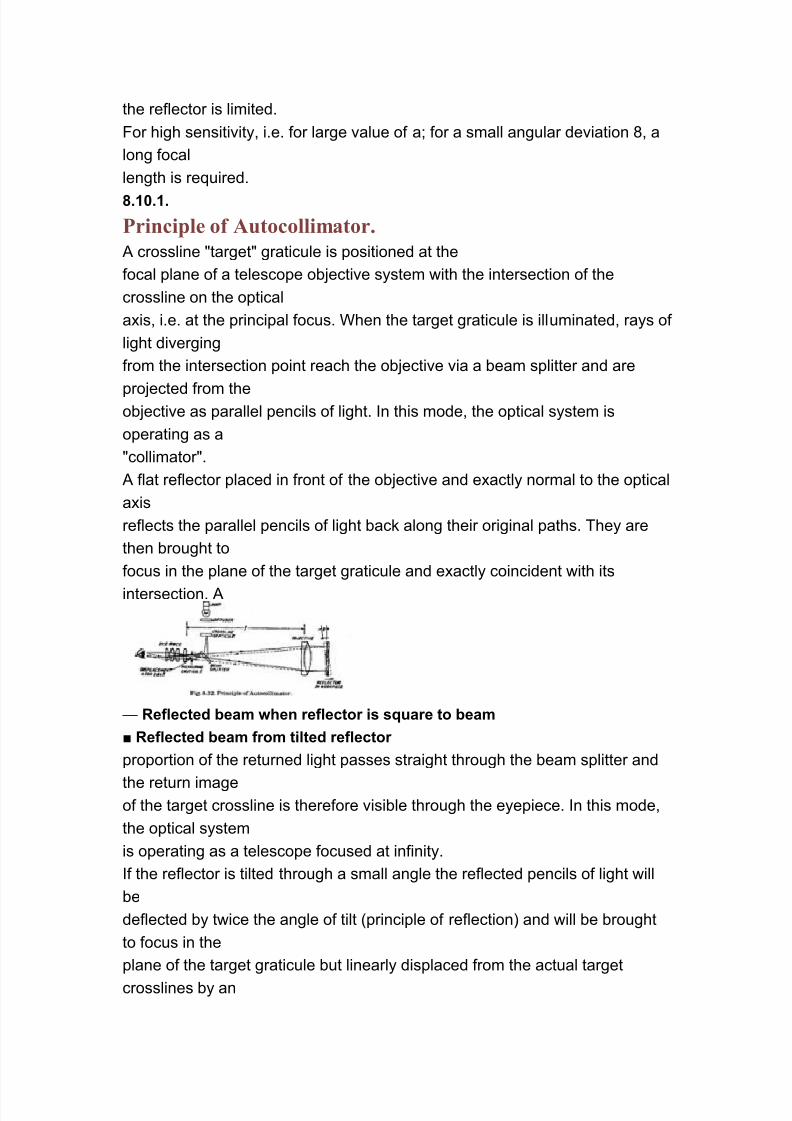
Principle of Autocollimator.
A crossline "target" graticule is positioned at the
focal plane of a telescope objective system with the intersection of the
crossline on the optical
axis, i.e. at the principal focus. When the target graticule is illuminated, rays of
light diverging
from the intersection point reach the objective via a beam splitter and are
projected from theobjective as parallel pencils of light. In this mode, the optical system is
operating as a
"collimator".
A flat reflector placed in front of the objective and exactly normal to the optical
axis
reflects the parallel pencils of light back along their original paths. They are
then brought to
focus in the plane of the target graticule and exactly coincident with its
intersection. A
— Reflected beam when reflector is square to beam
■ Reflected beam from tilted reflector
proportion of the returned light passes straight through the beam splitter and
the return imageof the target crossline is therefore visible through the eyepiece. In this mode,
the optical system
is operating as a telescope focused at infinity.
If the reflector is tilted through a small angle the reflected pencils of light will
be
deflected by twice the angle of tilt (principle of reflection) and will be brought
to focus in the
plane of the target graticule but linearly displaced from the actual target
crosslines by an
8/8/2019 m m Pakka Wala Hai - Copy
http://slidepdf.com/reader/full/m-m-pakka-wala-hai-copy 9/13
amount 28 x f.
Linear displacement of the graticule image in the plane of the eyepiece is
therefore
directly proportional to reflector tilt and can be measured by an eyepiece
graticule, optical
micrometer or electronic detector system, scaled directly in angular units. The
autocollimator
is set permanently at infinity focus and no device for focusing adjustment for
distance is
provided or desirable. It responds only to reflector tilt (not lateral displacement
of the reflector).
This is independent of separation between the reflector and the
autocollimator, assuming no
atmospheric disturbance and the use of a perfectly flat reflector.
Many factors govern the specification of an autocollimator, in particular its
focal length
and its effective aperture. The focal length determines basic sensitivity and
angular measuring
range. The longer the focal length the larger is the linear displacement for a
given reflector
tilt, but the maximum reflector tilt which can be accommodated is
consequently reduced.Sensitivity is therefore traded against measuring range. The maximum
separation between
reflector and autocollimator, or "working distance", is governed by the
effective aperture of the
objective, and the angular measuring range of the instrument becomes
reduced at long working
distances. Increasing the maximum working distance by increasing the
effective aperture then
demands a larger reflector for satisfactory image contrast. Autocollimator
design thus involves
many conflicting criteria and for this reason a range of instruments is required
to optimally
cover every application.
Air currents in the optical path between the autocollimator and the target
mirror cause
fluctuations in the readings obtained. This effect is more pronounced as
distance fromautocollimator to target mirror increases. Further errors may also occur due to
8/8/2019 m m Pakka Wala Hai - Copy
http://slidepdf.com/reader/full/m-m-pakka-wala-hai-copy 10/13
errors in
flatness and reflectivity of the target mirror which should be of high quality.
When both the autocollimator and the target mirror gauge can remain fixed,
extremely
close readings may be taken and repeatability is excellent. When any of these
has to be moved,
great care is required.
8.10.2.
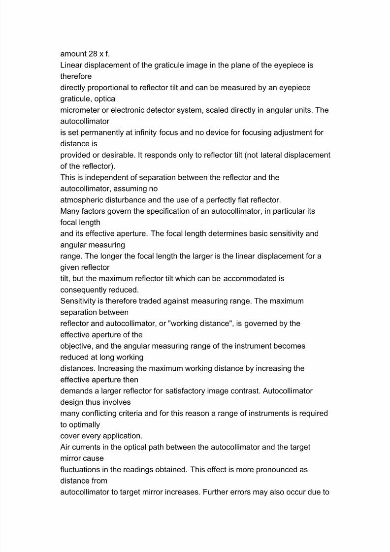
Laser Interferometer.
With laser interferometer it is possible to measure
length to an accuracy of 1 part in 106 on a routine basis. With the help of two
retro-reflectors,
placed at a fixed distance, and a length measuring laser interferometer thechange in angle
can be measured to an accuracy of 0.1 second. The device uses the Sine
principle. The line
joining the poles of the retro-reflectors makes the hypotenuse of the right
triangle. The change
in the path difference of the reflected beam represents the side of the triangle
opposite to the
angle being measured. Such laser interferometer can be used to measure an
angle upto ± 10
degrees with a resolution of 0.1 second.
The principle of operation is shown in Fig. 8.33.
Fig. 8.33. Interferometric measurement of angle.
8.10.3.
Photoelectric Microptic Autocollimator.Photoelectric setting makes
measuring and checking by autocollimator far simpler and faster. Micrometer
adjustment is
provided for setting, but coincidence of setting graticule and target image is
detected photo-
electrically, and shown on a meter as a null reading. This provides a high
degree of sensitivity
and repeatability, also reducing eye fatigue to a minimum. The eyepiece is
normally only used

8/8/2019 m m Pakka Wala Hai - Copy
http://slidepdf.com/reader/full/m-m-pakka-wala-hai-copy 11/13
to assist in initial setting-up.
Fig.8.34. Schematic diagram of Photo-electric autocollimator.
The photoelectric autocollimator is particularly suitable for calibrating
polygons, for
checking angular indexing and for checking small linear displacements.
It can be used as a visual autocollimator, if required, and is available with a
dark field
graticule as standard.
Fig. 8.34 shows a schematic of the operation of photoelectric autocollimator. It
consists
of a vibrating slit, a photoelectric detector, electronic amplifier for magnified
viewing on a
meter.
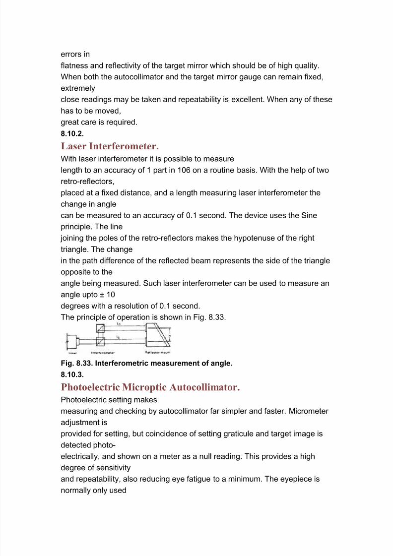
Operating Principle.
(Refer Fig. 8.35). The photoelectric detecting unit consists of
photocell and a vibrating slit which is attached to the micrometer screw. When
the slit is
positioned so that it vibrates about
the reflected image, the intensity of
light received by the photocell will
vary. The output waveform is
amplified and fed to a frequency dis-
criminator and meter which, in
effect, indicates the asymmetry of
the waveform. When the slit is posi-
tioned so that it vibrates symmetri-
cally about the image the meter
indicates a null reading, and the
angular displacement of the target
8/8/2019 m m Pakka Wala Hai - Copy
http://slidepdf.com/reader/full/m-m-pakka-wala-hai-copy 12/13
mirror can be read from the
micrometer.
Fig. 8.35. Schematic diagram of Photoelectric Autocollimator.
The autocollimator, with suitable reflecting surfaces or optical gauges, is
capable of
calibrating straightness, flatness, squareness or division of the circle.
8.10.4.
Automatic Position Sensing Autocollimators.Automatic position sensing
autocollimators provide fully automatic setting and display. Angular
displacement of the
reflector is displayed on a digital readout—eliminating any micrometer reading
for setting or measuring.
Automatic autocollimators can be used in cramped positions where it could be
impossible
to use a visual instrument, and no handling during measurement minimises
the danger of
accidental autocollimator movement.
Instruments measure in one plane only. For measuring in a second plane
perpendicular
to the first, the instrument is rotated through 90°. A dark field graticule is fitted
as standard.
Accuracy is unaffected by normal mains fluctuations or lamp ageing.
Automatic autocollimators are ideal for the repetitive checking of production
com-ponents, and for continuously monitoring angular displacement of slow
moving parts.
Operating Principle :
The vibrating slit image detecting system is similar to that
described for the photo-electric autocollimator, but in addition, the slit is
electrically biased
across the field. The amplitude and polarity of the biasing signal is dependent
upon the
misalignment of the slit with the return image. By this arrangement the slit is

8/8/2019 m m Pakka Wala Hai - Copy
http://slidepdf.com/reader/full/m-m-pakka-wala-hai-copy 13/13
biased to the
position straddling the image, at which the misalignment is negligible. The
current necessary
to hold the slit biased in this position is used to provide a direct angular
reading on a digital
readout.
8.10.5.