inspection of complex geometries using flexible phased ... · inspection of complex geometries...
TRANSCRIPT
17th World Conference on Nondestructive Testing, 25-28 Oct 2008, Shanghai, China
Inspection of Complex Geometries using Flexible Phased-Array Transducers
Gwénaël TOULLELAN 1, Arnaud NADIM 1, Olivier CASULA 1, Philippe DUMAS 2,
Elie ABITTAN 3, Loïc DOUDET3
1 CEA/LIST; Saclay, France 2 IMASONIC; Voray-sur-l’Ognon, France
3 EDF; France
Abstract
The piping inspection in nuclear power plants uses ultrasonic techniques, and their implementation is often performed with contact methods. The control is efficient, and the transmission is maximized when the wedge of the transducer is adapted to the surface of the component. However, the fixed shape of wedge can not be matched to all inspected zone when the component presents a variable surface (elbow, nozzles, butt weld…). In that case, the transmitted field is more or less disturbed and can lead to wrong flaw localization and characterization. To optimize the contact inspection with this type of component, flexible phased-array techniques have been developed, taking advantages from instrumentation and software developments. Firstly, the CIVA software is used to design the element arrangement and to evaluate its ability to detect defects. In operation, an embedded instrumentation measures in real time the current shape of the emitting surface. From this data, the M2M acquisition system calculates in real time the delay laws to be applied to the elements to compensate the deformation and thus to control the beam characteristics during the displacement of the probe. This first part of this paper presents experiments carried out to inspect a 2D real profile mock-up including artificial defects. Performances are evaluated using recent developments of the embedded algorithm to calculate delay laws in real time (multi-shot configuration). The second part shows examples of industrial inspections of a complex 3D mock-up using the 3D flexible array piloted by a robot. CIVA software reconstruction functionalities are also presented to reconstruct acquisition data according to the embedded parameters.
Keywords: Non Destructive Techniques, Ultrasonic Methods, Flexible Phased-Array Transducer
1. Introduction
Ultrasonic inspection of complex geometry components is usually performed with contact
methods, using conventional monolithic wedge transducers. The part in contact is adapted to a particular surface but in case of complex and varying geometry, the fixed shape of wedge can not be matched to all inspected zones. Any mismatch between the surface profile under test and the base of the wedge will produce an irregular coupling layer leading to beam distortions which reduce the inspection performance. The development of flexible ultrasonic arrays answers to the lack of adaptability to complex geometry of common ultrasonic sensors. 2D flexible arrays, suitable for 2D or 2.5-D pieces, have been developed and presented previously [1]. Experiments have shown their ability to focus with longitudinal and shear waves, to measure the emitting surface deformation with a good accuracy, and to calculate delay laws in real-time (embedded process with a repetition rate of 300 Hz). 3D flexible phased-array probes have also been developed in order to improve inspections of 3D geometries.
2
The first part presents recent validations carried out with the 2D flexible phased-array transducer using a multi-shot configuration to inspect a 2-D realistic profile mock-up containing artificial reflectors. The 2D flexible probe and the acquisition system are presented and experimental results obtained on the mock-up.
The second part presents the UT acquisition system and the 3D flexible phased-array applied on a mock-up including machined flaws such as notches and holes.
The third part presents the CIVA software, in particular reconstruction functionalities and the application of such tools to flaws positioning and sizing.
2. 2D Flexible Phased-Array Transducers
The flexible array transducer is composed of 32 linear piezoelectric elements, mechanically assembled to obtain a structure able to deform its shape up to 15 mm of radius of curvature. This ultrasound sensor integrates two other systems: a mechanical device pushing the elements on the surface and an instrumentation measuring the irregular profile met by the transducer. This profilometer is driven by a self-adaptive process, which measures the actual position of each element on a complex profile, computes the adapted delay laws, applies the delays and stores the reconstructed waveforms. This method insures to monitor the beam’s characteristics (orientation, focusing depth, steering…). Since 2007, this transducer is manufactured by IMASONIC Company who owns the commercialization license of the flexible phased-array transducers.
The transducer is fixed to a mechanical arm, which is driven by stepping motors. The device is driven by a real time UT acquisition system (provided by M2M Company), which controls the scanning, the electrical excitation of each element, the adaptive process and the data storage. The real time calculation of the delay laws is performed by the FPGA component of the system. The delay law takes into account the focus characteristics and the actual deformation of the emitting surface given by instrumentation. The repetition rate can be up to 300 Hz for the calculation and the application of one delay law. This particular operating mode using the embedded calculation functionality of the acquisition system requires the standard Multi-X acquisition system with only updated software which includes a specific library.
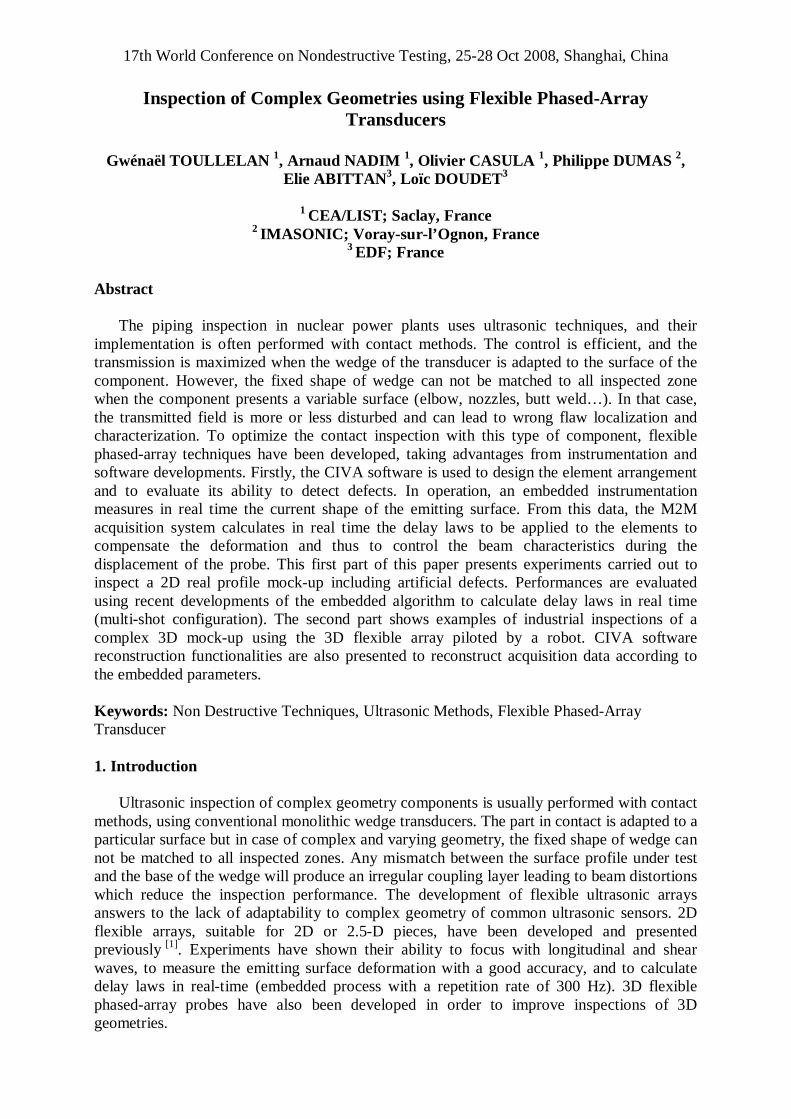
Figure 1. 2D flexible phased-array and the acquisition system MultiX 128 parallel channels.
3. Experimental Detection under a 2D Irregular Profile Mock-up
In order to validate the ability of the flexible probe in real adaptative mode with a multi-shot configuration, experiments have been carried out in a complex profile mock-up including artificial reflectors.

3
Acquisitions have been performed on a steel mock-up representative of a welded component with an irregular surface (measured on a realistic profile component). The mock up contains two identical series of four Side Drilled Holes (SDH) of 2 mm diameter, at 20, 30, 40 and 50 mm depth. The first set of SDH is located under a flat interface - as reference reflectors -, while the second set is placed under an irregular profile. The mock-up inspected is planar extrusion so the validation had been done using the 2D flexible transducer.
In order to cover the interested zone for one mechanical position of the probe, acquisitions were carried out using 20 focal points located between 0° to 55° in longitudinal waves at 40 mm depth. In this configuration, the repetition rate of the embedded process is about 100 Hz for the application of the 20 delay laws. As example, the 20 delays can be applied all the 0.2mm with a probe displacement of 20 mm/s.
Figure 2 shows ultrasonic signatures for two detection positions of the probe. In both cases, the set of SDH are detected with a good sensitivity and accurately positioned. These results show that the self-adaptive process allows mastering the characteristics of the different focused beams under the plane surface as well as under the irregular profile (orientation, focusing depth, steering…).
Figure 2. Sides Drilled Holes detection under a 2D realistic profile using a multi-shots configuration.
4. 3D Flexible Phased-Array Transducers
In order to extend the application field of the flexible phased-array presented previously,
limited to 2D irregular profiles, a 3D concept has been developed in order to conform over the incident plan as well as over the perpendicular plan. The acoustical unit is now composed of a matrix distribution of piezoelectric elements moulded in a soft resin.
The 3D array plotted Figure 3 is composed of 8x8 piezoelectric elements (2.5x2.5 mm²) moulded in a 50-mm-diameter resin. This probe presents an effective aperture of 27x31 mm². The mechanical part of the probe is composed of 3 by 3 square-matrix pistons which push the array to the surface of the component under test and measure the deformation of the surface,
4
thanks to displacement sensors. Each of the 64 piezoelectric elements is linked to his own independent emission-reception channel. Like the 2D concept, the 3D flexible phased-array probe is also manufactured by IMASONIC Company.
The MultiX-UT acquisition system presented previously is used to monitor, both the US signals and the voltages coming from instrumentation (deformation measurement). In this 3D configuration, the repetition rate of the embedded process is limited to 100Hz for one delay law, but will be improved by algorithm optimization.
The following results present the 3D flexible phased-array applied to the ultrasonic inspection of a nozzle mock-up.
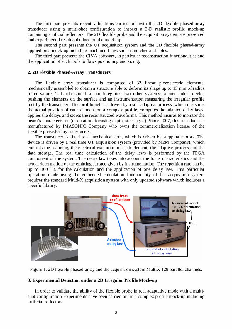
Figure 3. 3D flexible phased-array and the acquisition system MultiX 128 parallel channels.
5. 3D Mock-up Description and Inspection Configuration
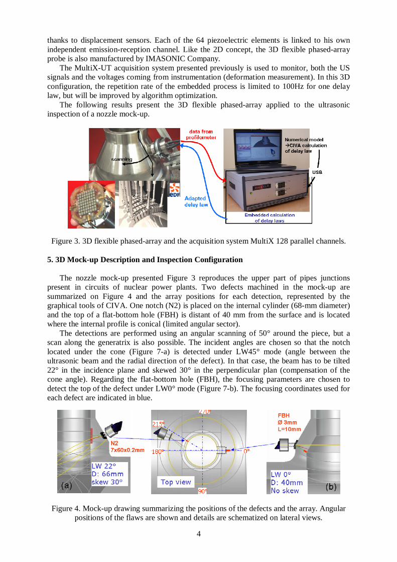
The nozzle mock-up presented Figure 3 reproduces the upper part of pipes junctions present in circuits of nuclear power plants. Two defects machined in the mock-up are summarized on Figure 4 and the array positions for each detection, represented by the graphical tools of CIVA. One notch (N2) is placed on the internal cylinder (68-mm diameter) and the top of a flat-bottom hole (FBH) is distant of 40 mm from the surface and is located where the internal profile is conical (limited angular sector).
The detections are performed using an angular scanning of 50° around the piece, but a scan along the generatrix is also possible. The incident angles are chosen so that the notch located under the cone (Figure 7-a) is detected under LW45° mode (angle between the ultrasonic beam and the radial direction of the defect). In that case, the beam has to be tilted 22° in the incidence plane and skewed 30° in the perpendicular plan (compensation of the cone angle). Regarding the flat-bottom hole (FBH), the focusing parameters are chosen to detect the top of the defect under LW0° mode (Figure 7-b). The focusing coordinates used for each defect are indicated in blue.
Figure 4. Mock-up drawing summarizing the positions of the defects and the array. Angular positions of the flaws are shown and details are schematized on lateral views.
5
3. Experimental Results
This experimental study presents the performances of the flexible array and in particular using the embedded functionality of the M2M acquisition system. The defects are detected using 50° degrees angular scanning presented Figure 3. All experiments have been performed using longitudinal mode.
3.1 Inspection from the cone/cylinder junction
In order to insure complex trajectories in 3D-geometry components, acquisitions were
carried out using a robot, equipment supplied by the federative platform GERIM. To detect the defects, the probe is fixed to the robot arm and move along the circumference of the nozzle mock-up. In this 3D configuration, the embedded process computes the delay laws with a 100-Hz-repetition rate. The acquisition is carried out with LW0° (from the local normal direction) for the detection of the flat-bottomed hole FBH located under the cylinder/cone junction.
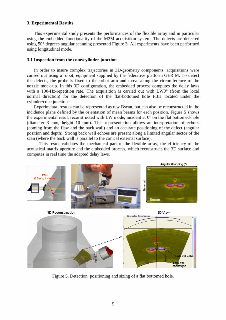
Experimental results can be represented as raw Bscan, but can also be reconstructed in the incidence plane defined by the orientation of mean beams for each position. Figure 5 shows the experimental result reconstructed with LW mode, incident at 0° on the flat bottomed-hole (diameter 3 mm, height 10 mm). This representation allows an interpretation of echoes (coming from the flaw and the back wall) and an accurate positioning of the defect (angular position and depth). Strong back wall echoes are present along a limited angular sector of the scan (where the back wall is parallel to the conical external surface).
This result validates the mechanical part of the flexible array, the efficiency of the acoustical matrix aperture and the embedded process, which reconstructs the 3D surface and computes in real time the adapted delay laws.
Figure 5. Detection, positioning and sizing of a flat bottomed hole.
6
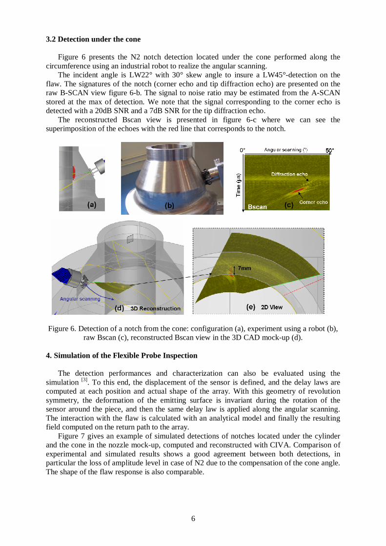
3.2 Detection under the cone
Figure 6 presents the N2 notch detection located under the cone performed along the circumference using an industrial robot to realize the angular scanning.
The incident angle is LW22° with 30° skew angle to insure a LW45°-detection on the flaw. The signatures of the notch (corner echo and tip diffraction echo) are presented on the raw B-SCAN view figure 6-b. The signal to noise ratio may be estimated from the A-SCAN stored at the max of detection. We note that the signal corresponding to the corner echo is detected with a 20dB SNR and a 7dB SNR for the tip diffraction echo.
The reconstructed Bscan view is presented in figure 6-c where we can see the superimposition of the echoes with the red line that corresponds to the notch.
Figure 6. Detection of a notch from the cone: configuration (a), experiment using a robot (b),
raw Bscan (c), reconstructed Bscan view in the 3D CAD mock-up (d).
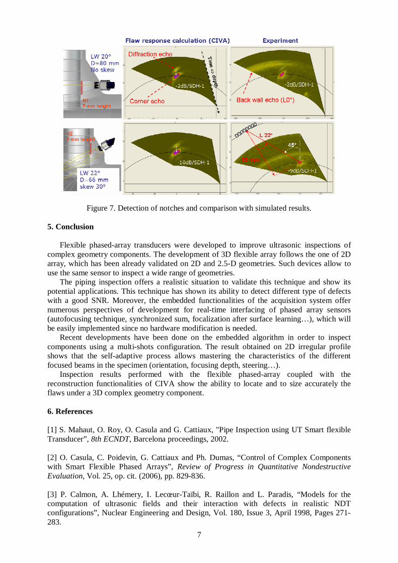
4. Simulation of the Flexible Probe Inspection
The detection performances and characterization can also be evaluated using the simulation [3]. To this end, the displacement of the sensor is defined, and the delay laws are computed at each position and actual shape of the array. With this geometry of revolution symmetry, the deformation of the emitting surface is invariant during the rotation of the sensor around the piece, and then the same delay law is applied along the angular scanning. The interaction with the flaw is calculated with an analytical model and finally the resulting field computed on the return path to the array.
Figure 7 gives an example of simulated detections of notches located under the cylinder and the cone in the nozzle mock-up, computed and reconstructed with CIVA. Comparison of experimental and simulated results shows a good agreement between both detections, in particular the loss of amplitude level in case of N2 due to the compensation of the cone angle. The shape of the flaw response is also comparable.
7
Figure 7. Detection of notches and comparison with simulated results.
5. Conclusion Flexible phased-array transducers were developed to improve ultrasonic inspections of
complex geometry components. The development of 3D flexible array follows the one of 2D array, which has been already validated on 2D and 2.5-D geometries. Such devices allow to use the same sensor to inspect a wide range of geometries.
The piping inspection offers a realistic situation to validate this technique and show its potential applications. This technique has shown its ability to detect different type of defects with a good SNR. Moreover, the embedded functionalities of the acquisition system offer numerous perspectives of development for real-time interfacing of phased array sensors (autofocusing technique, synchronized sum, focalization after surface learning…), which will be easily implemented since no hardware modification is needed.
Recent developments have been done on the embedded algorithm in order to inspect components using a multi-shots configuration. The result obtained on 2D irregular profile shows that the self-adaptive process allows mastering the characteristics of the different focused beams in the specimen (orientation, focusing depth, steering…).
Inspection results performed with the flexible phased-array coupled with the reconstruction functionalities of CIVA show the ability to locate and to size accurately the flaws under a 3D complex geometry component.
6. References [1] S. Mahaut, O. Roy, O. Casula and G. Cattiaux, "Pipe Inspection using UT Smart flexible Transducer”, 8th ECNDT, Barcelona proceedings, 2002. [2] O. Casula, C. Poidevin, G. Cattiaux and Ph. Dumas, “Control of Complex Components with Smart Flexible Phased Arrays”, Review of Progress in Quantitative Nondestructive Evaluation, Vol. 25, op. cit. (2006), pp. 829-836. [3] P. Calmon, A. Lhémery, I. Lecœur-Taïbi, R. Raillon and L. Paradis, “Models for the computation of ultrasonic fields and their interaction with defects in realistic NDT configurations”, Nuclear Engineering and Design, Vol. 180, Issue 3, April 1998, Pages 271-283.