influence of inert gases on the reactive high power pulsed
TRANSCRIPT

Influence of inert gases on the reactive high
power pulsed magnetron sputtering process of
carbon-nitride thin films
Susann Schmidt, Zsolt Czigany, Grzegorz Greczynski, Jens Jensen and Lars Hultman
Linköping University Post Print
N.B.: When citing this work, cite the original article.
Original Publication:
Susann Schmidt, Zsolt Czigany, Grzegorz Greczynski, Jens Jensen and Lars Hultman,
Influence of inert gases on the reactive high power pulsed magnetron sputtering process of
carbon-nitride thin films, 2013, Journal of Vacuum Science & Technology. A. Vacuum,
Surfaces, and Films, (31), 1, 011503.
http://dx.doi.org/10.1116/1.4769725
Copyright: American Vacuum Society
http://www.avs.org/
Postprint available at: Linköping University Electronic Press
http://urn.kb.se/resolve?urn=urn:nbn:se:liu:diva-89755

Influence of inert gases on the reactive high power pulsed magnetronsputtering process of carbon-nitride thin filmsSusann Schmidt, Zsolt Czigány, Grzegorz Greczynski, Jens Jensen, and Lars Hultman Citation: J. Vac. Sci. Technol. A 31, 011503 (2013); doi: 10.1116/1.4769725 View online: http://dx.doi.org/10.1116/1.4769725 View Table of Contents: http://avspublications.org/resource/1/JVTAD6/v31/i1 Published by the AVS: Science & Technology of Materials, Interfaces, and Processing Related ArticlesSingle Crystalline Oxygen-free Titanium Nitride by XPS Surf. Sci. Spectra 20, 1 (2013) The Si3N4/TiN Interface: 4. Si3N4/TiN(001) Grown with a −250 V Substrate Bias and Analyzed In situ usingAngle-resolved X-ray Photoelectron Spectroscopy Surf. Sci. Spectra 19, 62 (2012) The Si3N4/TiN Interface: 1. TiN(001) Grown and Analyzed In situ using Angle-resolved X-ray PhotoelectronSpectroscopy Surf. Sci. Spectra 19, 33 (2012) The Si3N4/TiN Interface: 5. TiN/Si3N4 Grown and Analyzed In situ using Angle-resolved X-ray PhotoelectronSpectroscopy Surf. Sci. Spectra 19, 72 (2012) The Si3N4/TiN Interface: 6. Si/TiN(001) Grown and Analyzed In situ using Angle-resolved X-ray PhotoelectronSpectroscopy Surf. Sci. Spectra 19, 82 (2012) Additional information on J. Vac. Sci. Technol. AJournal Homepage: http://avspublications.org/jvsta Journal Information: http://avspublications.org/jvsta/about/about_the_journal Top downloads: http://avspublications.org/jvsta/top_20_most_downloaded Information for Authors: http://avspublications.org/jvsta/authors/information_for_contributors
Downloaded 07 Mar 2013 to 130.236.83.30. Redistribution subject to AVS license or copyright; see http://avspublications.org/jvsta/about/rights_and_permissions

Influence of inert gases on the reactive high power pulsed magnetronsputtering process of carbon-nitride thin films
Susann Schmidta)
Thin Film Physics Div., Department of Physics (IFM), Link€oping University, SE-581 83, Sweden
Zsolt Czig�anyb)
Institute of Technical Physics and Materials Science, Research Centre for Natural Sciences,Hungarian Academy of Sciences, Konkoly Thege Mikl�os �ut 29-33. H-1121 Budapest, Hungary
Grzegorz Greczynski,c) Jens Jensen,d) and Lars Hultmane)
Thin Film Physics Div., Department of Physics (IFM), Link€oping University, SE-581 83, Sweden
(Received 13 September 2012; accepted 15 November 2012; published 7 December 2012)
The influence of inert gases (Ne, Ar, Kr) on the sputter process of carbon and carbon-nitride (CNx)
thin films was studied using reactive high power pulsed magnetron sputtering (HiPIMS). Thin solid
films were synthesized in an industrial deposition chamber from a graphite target. The peak target
current during HiPIMS processing was found to decrease with increasing inert gas mass. Time
averaged and time resolved ion mass spectroscopy showed that the addition of nitrogen, as reactive
gas, resulted in less energetic ion species for processes employing Ne, whereas the opposite was
noticed when Ar or Kr were employed as inert gas. Processes in nonreactive ambient showed
generally lower total ion fluxes for the three different inert gases. As soon as N2 was introduced
into the process, the deposition rates for Ne and Ar-containing processes increased significantly.
The reactive Kr-process, in contrast, showed slightly lower deposition rates than the nonreactive.
The resulting thin films were characterized regarding their bonding and microstructure by x-ray
photoelectron spectroscopy and transmission electron microscopy. Reactively deposited CNx thin
films in Ar and Kr ambient exhibited an ordering toward a fullerene-like structure, whereas carbon
and CNx films deposited in Ne atmosphere were found to be amorphous. This is attributed to an
elevated amount of highly energetic particles observed during ion mass spectrometry and indicated
by high peak target currents in Ne-containing processes. These results are discussed with respect to
the current understanding of the structural evolution of a-C and CNx thin films. VC 2013 AmericanVacuum Society. [http://dx.doi.org/10.1116/1.4769725]
I. INTRODUCTION
The possibility to tailor the microstructure and thus prop-
erties of carbon-based thin films for a variety of applications
justifies intense research.1–5 Especially, diamond-like carbon
(DLC) and fullerene-like carbon nitride (FL-CNx) roused
interest due to their different outstanding mechanical proper-
ties. DLC possesses superior wear resistance, hardness,
chemical inertness,2,6–8 and biocompatibility,9 whereas
FL-CNx exhibits an enormous resiliency (elastic recovery of
up to 98%), low wear and friction.10,11 This combination of
properties presents FL-CNx as an ideal material for wear
resistant applications. Since the properties of both materials
are determined by the energy of film forming species during
synthesis, we start by a short review of the current under-
standing. For DLC, the mechanical properties depend on
the variation of the sp3/sp2-C bonding ratio. An increased
amount of sp3-bonds leads to high hardness, approaching that
of diamond.3,12,13 Lifshitz et al.14 described the formation of
sp3 bonds by a local densification and subsequent relaxation
of the C network during high energy ion bombardment
[30–100 eV (Refs. 12, 15, and 16)]. Such deposition condi-
tions are supplied by magnetron sputtering, arc deposition, or
ion-beam deposition. In this context, the advantages of high
power impulse magnetron sputtering (HiPIMS also known as
HPPMS) should be considered as this deposition method gen-
erates an increased amount and energy of the ionized target
material, due to a high temporal electron density in the
HiPIMS plasma.17,18 Despite the comparatively high ioniza-
tion potential (IP¼ 11.26 eV, Table I) and low sputter yield
(0.197 atoms/ion for 500 eV Ar ions in the C/Ar discharge)
of C, an enhanced amount and energy of Cþ was as well
found for the C discharge in HiPIMS-mode.19 Nevertheless,
the ionized flux fraction of C in HiPIMS remains rather
low at 4.5%.20 Sarakinos et al. showed an increase in the
amount of sp3-bonds of up to 50% for DLC films prepared by
HiPIMS21 compared to DCMS (direct current magnetron
sputtering). Petrov et al.22 reported higher C ion energies
and, in correlation to this, also increased electron tempera-
tures during magnetron sputtering of C in Ne compared to
Ar, whereas the inert gas ion-to-C neutral arrival rates were
found to be similar for both inert gases. Aijaz et al. suggested
the utilization of Ne as inert gas while sputtering a graphite
target in HiPIMS mode, leading to an increased electron tem-
perature.23 The authors claimed a subsequent increase in Cþ
energy and flux, causing higher amounts of sp3-bonds in
C films. The impact of sputter mode and inert gas on the
a)Electronic mail: [email protected])Electronic mail: [email protected])Electronic mail: [email protected])Electronic mail: [email protected])Electronic mail: [email protected]
011503-1 J. Vac. Sci. Technol. A 31(1), Jan/Feb 2013 0734-2101/2013/31(1)/011503/13/$30.00 VC 2013 American Vacuum Society 011503-1
Downloaded 07 Mar 2013 to 130.236.83.30. Redistribution subject to AVS license or copyright; see http://avspublications.org/jvsta/about/rights_and_permissions

chemical bonding of the C and C-based films can thus be
considered substantial.
Sputtering with different inert gases while keeping the
same reactive gas and target material implies changes to
plasma and process parameters generally because of differ-
ences in collision cross sections, momentum transfer, and
ionization/excitation energies. Particularly, differences in
sputter yield, electron-impact ionization cross sections, inert
gas ionization energies (Ip), as well as metastable excitation
energies are of interest (Table I). Apart from the sputter
yield, these parameters influence electron impact ionization
and Penning ionization (ionization due to metastable inert
gas atoms)—the two major ionization mechanisms in the
PVD plasma. Moreover, the plasma electron temperature is
influenced by IP of the process gasses; increasing Ip impli-
cates an increased mean electron energy contributing to ioni-
zation.22,24 Therefore, the amount and the energy of ions in
the plasma are affected as well. Different inert gases also
determine the way secondary electrons are created25 with
respect to relative contributions from inert gas ions, recoils,
and electrons. In the case when graphite is sputtered in Ne,
electrons and ions contribute to the electron yield to approxi-
mately equal parts of �40% and �60%, respectively. If Kr
is used as inert gas, contributions to the electron yield of
ions dominate (�80%), recoiled atoms play an increased
role (�10%) and, in this case, a lower contribution for elec-
trons (�10%) was calculated.25 Adding N2, as reactive gas,
to the Ne discharge one of the major metal ionization mecha-
nisms in PVD—the Penning ionization—was found to play
a considerable role for the ionization of N2.26 In Ne/N2
discharges with N2 contents up to 50% a Penning mixture27
is formed. The ability of Ne to Penning ionize N2 according
to26,28
Ne� þ N02 ! Ne0 þ Nþ2 þ e� (1)
is attributed to the metastable states of Ne (Ne*) at 16.62
and 16.67 eV that exceed the ionization potential of N2
(IP¼ 15.6 eV) and N (IP¼ 14.53 eV). In the cathode sheath,
the conversion of kinetic energy to vibration/excitation and
dissociation of molecular nitrogen may occur in the two
steps:
Nþ2 ðfastÞ þ N02 ! Nþ�2 ðslowÞ þ N0
2
and
Nþ�2 ! Nþ þ N0; (2)
where � represents vibration excitation energy. The dissocia-
tive charge transfer (2) has threshold energy of �24 eV.28
Also possible are ionization and dissociation of N2 due to
electron impact or the ionization due to charge transfer from
inert gas ions.28 However, the existence of several metasta-
ble states of N2 allows manifold ionization and dissociation
pathways.29 Generally, for low-pressure discharges the pro-
cess gas ionization (Ne, Ar, Kr, N2) is likely to be governed
by electron impact ionization.
The evolution of the distinct FL-CNx microstructure was
first described theoretically by Gueorguiev et al.30 and arises
due to the incorporation of N into the C-matrix, causing the
formation of pentagon defects and this in turn provokes a
bending and cross linking of the graphene sheets. Those bent
cross linked graphene sheets give rise to the outstanding me-
chanical properties of this material. From an experimental
point of view, the mechanism behind the structural evolution
of FL-CNx—chemical sputtering—was first reported by
Hellgren et al.4 and later theoretically explained by Schluter
et al.31 Chemical sputtering is a temperature regulated chem-
ical desorption process taking place at the growth surface
procuring structure-defining CxNyþ-species (x, y� 2).
Recently, we published a comparative study, in which differ-
ent HiPIMS and DCMS processes for the deposition of FL-
CNx thin films were evaluated. The study revealed that a
mechanism that can be described as pulse assisted chemical
sputtering during reactive HiPIMS of a graphite target
promotes the structural evolution of CNx thin films toward a
FL structure and is taking place already at the target. Addi-
tionally, operating the graphite target with short, but high
power pulses, as it is done in HiPIMS, produces an increased
average energy and amount of Cþ, but also increased
amounts of CxNyþ-species.19
It becomes evident that HiPIMS process and plasma
parameters are distinctly different for each of the gases and
that a wide process window can be spanned in their utiliza-
tion. Former DCMS studies on CNx thin films presented the
substrate temperature (Ts), the energy of film-forming ions,
and the nitrogen-to-argon flow ratio fN2=Ar as most important
growth parameters in order to modify the CNx thin film
microstructure and thus properties.11 We expect vast possi-
bilities to control and influence CNx thin film formation dur-
ing HiPIMS. The role of different inert gases on reactive
HiPIMS deposition of CNx films is, however, unexplored. In
TABLE I. Collection of process relevant data for C/inert gas/N2-discharges.
Inert gases Reactive gas species Target material
Ne Ar Kr N2 N C
1st ionization energy (eV), IP 21.56 15.75 13.99 15.6 14.53 11.26
Total ionization cross section (10�17 cm2) at 25 eV 0.25 (Ref. 58) 16.5 (Ref. 58) 19.5 (Ref. 58) 1.17 (Ref. 59) 14.4 (Ref. 59)
Metastable excitation energy (eV) (Ref. 43) 16.62 16.71 11.55 11.72 9.91 9.99
Total sputter yield for C (atoms/ion) at 100 eVa 0.02 0.005 0.0001 0.009 0.04 0.07
aAs obtained by TRIM (Ref. 60) simulations for ion energies of 100 eV and incidence angles of 0� with respect to the target surface.
011503-2 Schmidt et al.: Influence of inert gases on the reactive HiPIMS process 011503-2
J. Vac. Sci. Technol. A, Vol. 31, No. 1, Jan/Feb 2013
Downloaded 07 Mar 2013 to 130.236.83.30. Redistribution subject to AVS license or copyright; see http://avspublications.org/jvsta/about/rights_and_permissions

the presented study, we investigate the effect of three differ-
ent inert gases (Ne, Ar, Kr) on HiPIMS process and plasma
parameters as well as on the chemical bonding and micro-
structure of CNx thin films. Conclusions on the growth as
well as structure-defining mechanisms are drawn from the
evaluation of the plasma processes (ion mass-spectrometry,
target current waveforms) in combination with thin film
characterization [high resolution transmission electron mi-
croscopy (HRTEM), selected area electron diffraction
(SAED), and x-ray photo electron spectroscopy (XPS)].
II. EXPERIMENT DETAILS
Ion mass-spectrometry measurements and film deposi-
tions were carried out in an industrial CC800/9 coating sys-
tem (CemeCon AG, Germany). Plasma characterization and
film depositions were made in HiPIMS mode. Our investiga-
tions were performed using one rectangular target with an
area of 440 cm2. Pure graphite targets (Tokai CARBON
Deutschland GmbH) were sputtered in Ne, Ar, or Kr and
additionally in inert gas/N2 atmosphere at a constant pres-
sure of 400 mPa. The amount of N2 in the working gas,
defined by
fN2
finertgas þ fN2
� 100%; (3)
where fN2and finertgas represent the flow of N2 and inert gas,
respectively, ranged between 14% and 100%. In power-
regulated mode a frequency of 300 Hz was applied. For ion
mass spectrometry measurements of Ne-containing proc-
esses, an average power of 1800 W was applied to the cath-
ode, whereas for processes involving Kr an average power
of 1400 W was used. Reference measurements for both
power settings (1400 and 1800 W) were conducted in an Ar-
containing atmosphere. An average power of 1800 W was
chosen for Ne-containing discharges due to the fact that
more stable discharge conditions during ion mass spectros-
copy measurements were achieved with this slightly higher
average power. The pulse width was kept constant in all
processes at 200 ls. The measurements took place at room
temperature. Furthermore, since the mass spectrometer ori-
fice is grounded no additional bias voltage was applied.
IEDFs were measured in a time-averaged and time-
resolved mode for the most abundant ionic plasma species,
namely Cþ, C2þ, Nþ, N2
þ, Neþþ, Neþ, Arþ, Arþþ, Krþþ,82Krþ, 84Krþ, 86Krþ, CNþ, and C2N2
þ. The measurements
were performed with a PSM003 unit from Hiden Analytical,
UK, operated with a quadrupole mass analyzer sensitive to
masses up to 300 amu with a resolution of 0.1 amu. In order
to allow comparisons, the measurements were carried out
with identical global settings (including detector, extractor,
and quadrupole voltages and currents) after fine-tuning with
regards to mass 12, assigned to Cþ. The position of the spec-
trometer orifice relative to the target with regards to the
angle as well as spatial and lateral was comparable to the
arrangement of the substrates to the target. A distance of
60 mm between target and the spectrometer orifice was kept
similar for all measurements and corresponds also to the
spacing between target and substrate during thin film deposi-
tion. Time-averaged data were recorded between �0.5 eV
and 50 eV with step widths of 0.5 eV. The dwell time was set
to 100 ms, which corresponds to an information depth of at
least 30 pulses in each data point. Acquisitions for time-
resolved ion mass-spectrometry measurements were trig-
gered by the signal from a Tektronix DPO4054 500 MHz
bandwidth digital oscilloscope. The delay time, related to
the onset of the power pulse to the cathode, ranged from
40 ls up to 280 ls with an increment of 20 ls. A total acqui-
sition time of 1 ms per data point was applied. Time-
resolved mass spectrometry was carried out for ion energies
ranging between 0 and 30 eV with a resolution of 0.5 eV.
The ion time-of-flight (TOF) within the mass spectrometer
was corrected for presented time-resolved data, with the
purpose to show the plasma composition at the spectrometer
orifice (substrate surface) rather than at the spectrometers’
detector. Therefore, the approach suggested by Bohlmark
et al.32 was used. The plasma species and their calculated
corresponding TOF are listed in Table II. Naturally, the TOF
of ions within the mass spectrometer depends on their initial
kinetic energy. However, for kinetic energies below 100 eV,
the TOF varies not more than 10%. Since this is the case for
the applied processes, a mean particle energy of 8 eV was
used for all TOF calculations. During ion mass spectrometry
measurements the target current and target voltage wave-
forms were recorded with a Tektronix DPO4054 500 MHz
bandwidth digital oscilloscope.
Thin films were deposited on Si(001) substrates using an
average power of 1400 W for all inert gases and inert gas/N2
mixtures. The above presented settings regarding the pulse
width and frequency were used as well during deposition. In
addition, a pulsed bias voltage (Vb) of �100 V, synchronized
with the cathode high voltage pulse, was applied to the sub-
strate table. Two different substrate temperatures (Ts) of
110 �C and at 430 �C were chosen for the thin film deposi-
tion. Thin films deposited at a low substrate temperature of
110 �C were evaluated regarding their deposition rate (Rd)
and N content, in order to allow comparisons with the results
gained by plasma characterization. The effect of the inert
gases on the structural evolution of the CNx films is pre-
sented here for samples deposited at 430 �C, since substrate
TABLE II. Measured ion species together with their mass/charge ratio and
TOF correction.
Ion m/e TOF correction (ls)
Cþ 12 32
C2þ 24 45
CNþ 26 47
C2N2þ 52 67
Neþ 20 41
Neþþ 10 29
Arþ 40 59
Arþþ 20 4184Krþ 84 85
Krþþ 42 60
011503-3 Schmidt et al.: Influence of inert gases on the reactive HiPIMS process 011503-3
JVST A - Vacuum, Surfaces, and Films
Downloaded 07 Mar 2013 to 130.236.83.30. Redistribution subject to AVS license or copyright; see http://avspublications.org/jvsta/about/rights_and_permissions

temperatures above 300 �C were found to be necessary to
form the FL-structure.33,34
Deposition rates were determined with cross-sectional
scanning electron microcopy (SEM, LEO 1550 Gemini,
Zeiss, Germany). The composition of CNx films were eval-
uated using time-of-flight elastic recoil detection analysis
(ToF-ERDA) applying an 36 MeV127I9þ ion beam at 22.5�
incidence angle relative to the surface.35,36 Here, data were
stored event by event in list mode and analyzed off-line.
Only the data obtained during the first minutes (yielding
sufficient statistics) were used.
X-ray photoelectron spectroscopy (XPS) was performed
with a Quantum 2000 spectrometer from PHI Physical
Electronics, Inc., USA, using a monochromatic Al(Ka) X-ray
beam (h�¼ 1486.6 eV) and a chamber pressure of less than
1.4� 10�6 Pa. XPS data of the C1s, N1s, and O1s regions
were collected after the samples were sputter-cleaned for
10 min with 500 eV Arþ ions. The lowest sputter energy pos-
sible was chosen as the CNx bonding structure was reported
to be easily affected and might also be accompanied by a
preferential sputtering of N.37 Automatic charge compensa-
tion was applied, due to the fact that CNx films typically
show elevated electrical resistivities38 compared to conduct-
ing materials. Obtained spectra were fitted using Voigt peak
shape, with the Lorentzian contribution not exceeding 20%.
The full width at half maximum (FWHM) was restricted to
1.7 eV for the main contributions C1 and C2 of the N1s core
level spectra, whereas the FWHM of the minor contributions
C3 and C4 was restricted to 2.0 eV. A Shirley-type back-
ground was used and all spectra were referenced to the CAC
(CACH) bond at 284.5 eV.
Cross-sectional TEM was carried out on cleaved sam-
ples.39 These samples were examined in a Tecnai G2 TF 20
UT TEM (FEI, The Netherlands). SAED patterns were
exposed with a CCD camera in the same instrument and
processed with diffraction software.40 The degree of struc-
turing (fullerene-like, graphitic or amorphous) was assessed
in evaluating peak intensities of the rings at �3.5 A and
� 2 A (I3.5A and I2A), extracted from the SAED pattern. The
relative peak intensity (R ¼ I3:5A
=I2A
) describes the degree
of graphitic short range ordering in CNx and C-based
materials.41
III. RESULTS AND DISCUSSION
A. Target current and target voltage waveformsfor different inert gases
In order to investigate the effect of different inert gases
on the sputter process for the deposition of a-C and CNx thin
films, the target current I(t) and target voltage U(t) wave
forms are evaluated first. In the case of industrial HiPIMS
processing operated on large-area cathodes, the shape of the
target current and target voltage traces depends to large
extent on the size of the capacitor bank of the pulsing unit.
The resulting voltage pulse is far from an ideal, rectangular
form, and often exhibits a sudden drop in amplitude with
pulse time. Examples of such behavior can be seen in Fig. 1,
where current and voltage waveforms for processes in pure
Ne [cf. black thin line, PTav¼ 1800 W)] and pure Kr [cf.
black bold line, PTav¼ 1400 W)] are presented. As reference,
the corresponding I(t) and U(t) characteristics of equivalent
processes (the same frequency, pressure, process tempera-
ture, and pulse duration) employing Ar for both power set-
tings are additionally included in Fig. 1. Evident is the high
peak target current (I) of �245 A as the graphite target is
sputtered in pure Ne atmosphere in comparison to I� 180 A
for the process in pure Ar atmosphere. In contrast to this
is the I for the discharge in Kr, as it rises to �100 A at an
average power of 1400 W and is thus compared to I� 126 A
of the Ar discharge at 1400 W (cf. gray bold line Fig. 1)
rather low.
The discharge current comprises ion and electron current.
Increased I values indicate in a first approximation elevated
amounts of charged species that form in the vicinity of the tar-
get as different noble gases are used for the sputter process.
Factors that influence the over-all amount of charged sputtered
species and consequently contributing to I are as follows:
(i) The sputter yield, as more particles are sputtered, the
probability for ionization is enhanced. The sputter
yield of carbon increases for the used noble gases in
the sequence Kr, Ar, Ne (Table I).
(ii) The first ionization potential IP of the inert gas; an
increased IP implies elevated electron tempera-
tures,22,24 contributing to ionization and thus, I. The
ionization potential increases with decreasing inert
gas atomic number (Table I).
(iii) The total ionization cross section for electron energies
below 50 eV increase in the sequence Ne, Ar, and Kr,
(Table I).42 Here, it should be taken into account that
electron energies are possibly considerably higher for
Ne processes23 and decrease with increasing atomic
number of the inert gas. Thus, differences in ioniza-
tion cross sections may not be as crucial.
FIG. 1. Target current and target voltage waveforms for HiPIMS processes
comparing different inert gases; Ne (Pav¼ 1800 W, black thin line) and the
corresponding Ar process (Pav¼ 1800 W, gray thin line) as well as Kr
(Pav¼ 1400 W, black bold line) with corresponding Ar process
(Pav¼ 1400 W, gray bold line). The inset presents a magnification of the
first 35 ls of I(t) and depicts the delay in the raise of the target current.
011503-4 Schmidt et al.: Influence of inert gases on the reactive HiPIMS process 011503-4
J. Vac. Sci. Technol. A, Vol. 31, No. 1, Jan/Feb 2013
Downloaded 07 Mar 2013 to 130.236.83.30. Redistribution subject to AVS license or copyright; see http://avspublications.org/jvsta/about/rights_and_permissions

(iv) The excitation energies of the metastable energy lev-
els for the three inert gases increase with decreasing
inert gas atomic number [Table I (Ref. 43)], whereas
the excitation energies for Ar (11.55 and 11.72 eV) are
just above the first ionization potential of C
(11.26 eV). Therefore, it is reasonable to conclude that
Penning excitation and ionization occurs only as the
graphite target is sputtered in Ar and Ne atmosphere.
(v) The secondary electron emission yield (cSE)33 is consid-
ered as well, as it merely depends on Ip of the used inert
gas in the case the graphite target is sputtered in metallic
mode.In order to estimate cSE, the empirical equation44
cSE ¼ 0:032ð0:78 IP � 2uÞ (4)
is valid for HiPIMS processes where particle energies are
below 100 eV. In Eq. (4), IP resembles the ionization poten-
tial of the impinging particles (sputter gas) on the target sur-
face and u the work function of the target material. A three
times higher cSE was calculated for the C/Ne discharge com-
pared to the C/Ar discharge. In case the graphite target is
sputtered in Kr, cSE yielded 30% of the value for the C/Ar
discharge. This is mirrored in the peak target current of the
C discharge for the three different inert gases (Fig. 1).
Another remarkable feature is the delay in the onset of
the target current pulse (cf. inset in Fig. 1). It is attributed to
a number of process parameters such as gas pressure45 and
target material,46 and the process gas composition.47 In the
presented study, the time dependence of the electrical break-
down (time lag until the target current rises) was observed
for different inert gases as well as for different reactive pro-
cess gas mixtures and is demonstrated in Figs. 1 (inset) and
2(a) and 2(b). Discharges in pure Ar and Kr show a delay of
6 ls, whereas the electrical breakdown for Ne was observed
after 22 ls (inset, Fig. 1). Due to the comparatively high IP
and high metastable excitation energies of Ne, the energy
loss of fast electrons is more substantial during the exciting
and ionization of noble gas atoms, than for Kr and Ar.
Discharges in pure N2 atmosphere yield an electrical
breakdown delay of 9 ls and 15 ls for processes with an av-
erage power of 1800 and 1400 W, respectively. Hala et al.40
investigated the I(t) characteristics of Cr in a reactive Ar/N2
atmosphere thoroughly. They conclude that the delayed rise
of the current is an indication of a delayed gas breakdown
due to energy loss of electrons by excitation and dissociation
of N2 (electron quenching), since molecular nitrogen has
several vibrational and rotational excitation levels that are
accessible for energy absorption. However, for reactive car-
bon discharges involving N2, apart from electron quenching,
rather complex sputter mechanisms occur at the target sur-
face and in the vicinity of the target (i.e., chemical desorp-
tion processes, excitation and dissociation of nitrogen, and
CxNy molecules). Additionally, not only the properties of the
sputter gas are considered to be changed, but also those of
the graphite target surface. Therefore, the onset delay of the
current pulse in the case of N2 and inert gas/N2 mixtures
may have more than one explanation.
In Figs. 2(a) and 2(b), the current wave forms for reactive
processes employing N2 in different N2/inert gas [for N2/Ne,
N2/Ar, cf. Fig. 2(a) and N2/Ar, N2/Kr cf. Fig. 2(b)] mixtures
are presented. For reactive processes in Ar or Ne [thin and
bold lines, respectively, Fig. 2(a)], I has a minimum as the
process is carried out in �50% N2 with values of 166 and
160 A for Ar and Ne, respectively. The addition of more N2
to the process gas mixture results in a slight increase of I to
170 A as the graphite target is sputtered in pure N2. This
accounts for 70% of the I when pure Ne is used and is
mainly attributed to differences in cSE as the sputter gas
chemistry (different IP of the inert gas/reactive gas mix), but
additionally also the work function of the target changes.
With the introduction of N2 in the HiPIMS sputter process,
the target surface chemistry changes, since dangling C bonds
become passivated by nitrogen and a C-N surface layer
builds up eventually. The acting mechanisms were investi-
gated and explained in detail for the C/Ar/N2 system in
Ref. 17 and are assumed to apply for the C/Kr/N2 and C/Ne/
N2 sputter processes as well. Apart from differences in cSE,
electron-quenching effects may contribute to the decreased I
values when N2 is introduced into the reactive HiPIMS pro-
cess, which were observed for the Ar, Ne, and Kr discharges.
This quenching effect reduces the probability of electron
impact ionization, since electrons lose their energy by exci-
tation of N2.47,48
The temporal evolution of I is distinct; as it shifts toward
the pulse end with the introduction of N2 into the Ne dis-
charge. A further increase of N2 in the plasma (>14%)
causes the peak target current to appear early until it eventu-
ally emerges at the same pulse time (66 ls) similar to when
the process is carried out in pure N2 compared to the process
in pure Ne. As graphite is sputtered in Kr [cf. Fig. 2(b)] mix-
tures, the opposite is recorded; the target current shows its
maximum (�100 A) in the middle of the pulse (at �101 ls).
Here, an increase of the nitrogen content in the sputter gas
FIG. 2. (Color online) (a), (b) Target current waveforms for reactive HiPIMS
processes comparing different N2 contents in the inert gases; (a) I(t) for dis-
charges carried out at Pav¼ 1800 W in Ne/N2 (bold lines) and in Ar/N2 (thin
lines); (b) I(t) for discharges carried out at Pav¼ 1400 W in Kr/N2 (bold
lines) and in Ar/N2 (thin lines).
011503-5 Schmidt et al.: Influence of inert gases on the reactive HiPIMS process 011503-5
JVST A - Vacuum, Surfaces, and Films
Downloaded 07 Mar 2013 to 130.236.83.30. Redistribution subject to AVS license or copyright; see http://avspublications.org/jvsta/about/rights_and_permissions

causes the target current to peak gradually earlier during the
pulse. The temporal evolution observed in the I(t) wave-
forms shown in Figs. 2(a) and 2(b) does not only depend on
the time delay required for the current to rise (electrical
breakdown). If corrected for this time delay, the instant the
target current peaks still depends on the applied sputter gas
as well as average power. In this context, the ionization and
excitation mechanisms of N2, Kr, Ar, Ne, and C are impor-
tant. Also, the rather complex sputter mechanisms, including
next to physical sputtering also temperature dependent
chemical desorption processes of CxNy species from the
changed target surface19 should be considered.
B. Effects of inert gases on the ion compositionof the C/N2/inert gas HiPIMS discharge
Two main components are usually observed in time-
averaged IEDFs recorded for HiPIMS processes; a low-energy
portion that mirrors thermalized ions and a high-energy tail.
This high-energy tail comprises three main components: the
probability function of electron impact ionization, the proba-
bility function for collisions between target ions and inert gas
neutrals, and the energy transmission function of the mass
spectrometer.49 Essentially, these components are observed in
the present experiments; however, their fractions vary to a
large extent in C plasmas of different inert gases.
Figures 3(a)–3(m) shows IEDFs of the most abundant spe-
cies arriving at the substrate/orifice, recorded for discharges
of graphite in different N2/Ne mixtures [Figs. 3(a)–3(f)] and
corresponding processes employing Ar [Figs. 3(g)–3(m)]
instead of Ne. Most prominent are the IEDFs of Cþ and Neþ
[Figs. 3(a) and 3(b)] obtained for 0% N2 (black lines) 14%
N2 (gray lines) in the sputter gas. In both cases, a broad
energy distribution of target and gas ions is evident. This is in
contrast to the IEDFs obtained in reactive sputter mode
employing 33% N2. A further increase of the reactive gas
content causes the high-energy tails in the IEDFs of Cþ, Neþ,
and Nþ [Figs. 3(a), 3(b), and 3(f)] to move constantly toward
lower energies, which is in contrast to the respective Ar proc-
esses [Figs. 3(g), 3(h), and 3(m)]. Here, IEDFs of Cþ, Arþ,
and Nþ broaden slightly with the addition of reactive gas
although not to the same extent. In fact, IEDFs of discharges
involving Ne are more affected by the addition of N2 than
those for discharges involving Ar. This can be attributed to
differences in nature of Ar and Ne with respect to N2 and the
effects of Ip on the discharge as discussed above.
Striking is the comparison of N2þ and Nþ IEDF’s for the
Ne discharge with 14% of N2 [gray lines, Figs. 2(c) and 2(f)];
only a small quantity of N2þ ions at low energies (�2.5 eV)
was recorded, whereas a comparatively large amount of Nþ
ions with the high-energy tail peaking at �23 eV was meas-
ured for the same process. This indicates enhanced ionization
and dissociation mechanisms according to reactions (1) and
(2) for N2 in the Ne/N2 mixtures containing �14% N2.
Itagaki et al. correlated the electron temperature and density
with the dissociation rate of N2 in an ECR (electron cyclotron
resonance) plasma and found for both parameters increased
rates.50 This in combination with increased plasma
FIG. 3. (Color online) (a)–(m) Time-averaged IEDFs of the most abundant precursor species recorded for HiPIMS discharges at Pav¼ 1800 W in Ne and Ne/
N2 [(a)–(f)] as well as Ar and Ar/N2 [(g)–(m)] of graphite.
011503-6 Schmidt et al.: Influence of inert gases on the reactive HiPIMS process 011503-6
J. Vac. Sci. Technol. A, Vol. 31, No. 1, Jan/Feb 2013
Downloaded 07 Mar 2013 to 130.236.83.30. Redistribution subject to AVS license or copyright; see http://avspublications.org/jvsta/about/rights_and_permissions

temperatures due to the comparatively high IP of Ne supports
the assumption of Penning ionized N2 due to Ne, undergoing
a subsequent dissociative charge transfer [cf. reactions (1)
and (2)].
Apart from this, IEDFs for CNþ and N2þ of the Ne and
the Ar plasma do not vary much in energy, merely the
amount of ions increases with the increase of N2. Doubly
charged Ne ions [Fig. 3(e)] show a broad distribution and
low intensity but were only observed for processes up to
33% of N2 in the sputter gas, whereas Arþþ ions [Fig. 3(l)]
were recorded at lower energies peaking at a maximum of
5 eV for all presented Ar-containing processes. Due to the
short distance of 60 mm between the target and the mass
spectrometers orifice, the lowered collision probability in
the Ne discharge and a relatively high average power of
1800 W, significant amounts of thermalized species were
only observed for Arþ ions.
Figures 4(a)–4(f) present the comparison of IEDFs
obtained from the most abundant precursor species of C dis-
charges in Kr/N2 and Ar/N2 ambient for comparable process
settings. Generally, IEDFs recorded for discharges carried
out in Kr-containing atmosphere exhibit narrower energy
distributions than the equivalent Ar processes. The Cþ
signals [Fig. 4(a)] reside at comparable energies (�1.5 eV)
as the N2 content in the sputter gas increases and approaches
50% N2 in the sputter gas. The process in pure N2 atmos-
phere yields a broadening of the Cþ energy distribution
peaking at �3 eV. The respective Ar processes [Fig. 4(g)]
yield Cþ energy distributions that are hardly affected by
increasing N2 contents. Here, the IEDF values peak between
1.5 and 3.5 eV.
Examples for IEDFs of Kr-isotopes 84Krþ and 83Krþ are
presented in Fig. 4(b) and 4(e), respectively, since the quali-
tative comparison of their shape can be used to verify the
measurements. The distributions of both species show simi-
lar features, as should be the case, since both species origin
from the same source (inert gas), and hardly vary in mass or
dimension. The IEDFs of 84Krþ and 83Krþ are very narrow
and consist of mainly thermalized ions with little depend-
ence on the N2 content in the sputter gas. Moreover, the rela-
tive abundance of the Kr-isotopes 82Krþ, 83Krþ, 84Krþ, and86Krþ (not shown here) was extracted from the correspond-
ing distributions to yield in 13.8, 16.9, 54.2, and 15.0%,
respectively. This is in fair agreement with data published by
Yoon and Glab,51 for the respective abundances 11.6, 11.5,
57, and 17.3%. 78Krþand 80Krþ were omitted in our meas-
urements and their evaluation, due to their low abundance of
0.35% and 2.25%, respectively.51 In contrast to Krþ, broader
distributions are obtained for Arþ under comparable process
conditions in Ar-containing discharges. Here, the peak value
of the high-energy tail moves from 5 to 2 eV as soon as N2 is
added to the process and remains there with the further
increase of reactive gas [Fig. 4(h)]. It is noted that the differ-
ence in average power (1400 and 1800 W) for Ar-containing
processes has no significant affect on ion energies of the
recorded species. In all Kr-containing processes, doubly
charged Kr ions (not shown here) were present and yielded
�50% of the energy compared to Arþþ [Fig. 4(l)].
FIG. 4. (Color online) (a)–(m) Time-averaged IEDFs of the most abundant precursor species recorded for HiPIMS discharges at Pav¼ 1400 W in Kr and Kr/N2
[(a)–(f)] as well as Ar and Ar/N2 [(g)–(m)] of graphite.
011503-7 Schmidt et al.: Influence of inert gases on the reactive HiPIMS process 011503-7
JVST A - Vacuum, Surfaces, and Films
Downloaded 07 Mar 2013 to 130.236.83.30. Redistribution subject to AVS license or copyright; see http://avspublications.org/jvsta/about/rights_and_permissions
Distributions of N2þ and Nþ, recorded for Kr and Ar-
containing processes at 1400 W [Figs. 4(c), 4(f), 4(i), and
4(m), respectively], exhibit higher energies as the N2 content
in the sputter gas increases. This was also observed in IEDFs
of N2þ and Nþ for the discharge of C/Ar/N2 at 1800 W.
Similar processes in Ne-containing atmosphere showed the
opposite effect; the mean energy of Nþ decreased as more N2
is introduced. This demonstrates the effect of the Penning
mixture as C is sputtered in Ne with small amounts of N2.
Moreover, for Kr/N2-containing processes with more than
14% N2 significant portions of thermalized N2þ and Nþ were
recorded, owing to the higher collision cross sections in the
Kr/N2 plasma.
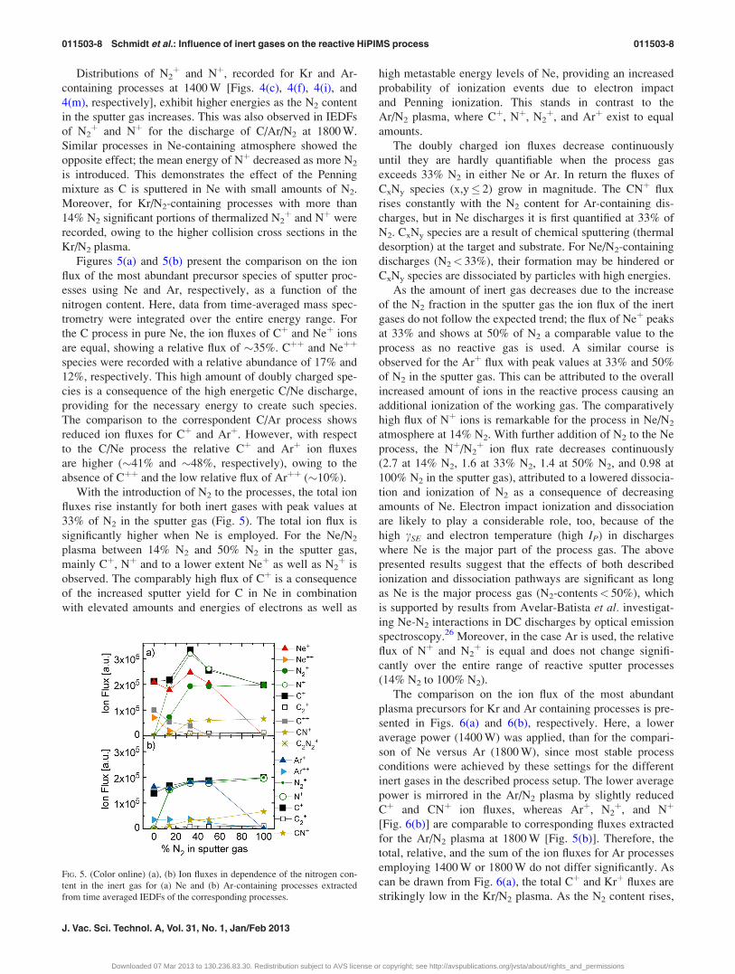
Figures 5(a) and 5(b) present the comparison on the ion
flux of the most abundant precursor species of sputter proc-
esses using Ne and Ar, respectively, as a function of the
nitrogen content. Here, data from time-averaged mass spec-
trometry were integrated over the entire energy range. For
the C process in pure Ne, the ion fluxes of Cþ and Neþ ions
are equal, showing a relative flux of �35%. Cþþ and Neþþ
species were recorded with a relative abundance of 17% and
12%, respectively. This high amount of doubly charged spe-
cies is a consequence of the high energetic C/Ne discharge,
providing for the necessary energy to create such species.
The comparison to the correspondent C/Ar process shows
reduced ion fluxes for Cþ and Arþ. However, with respect
to the C/Ne process the relative Cþ and Arþ ion fluxes
are higher (�41% and �48%, respectively), owing to the
absence of Cþþ and the low relative flux of Arþþ (�10%).
With the introduction of N2 to the processes, the total ion
fluxes rise instantly for both inert gases with peak values at
33% of N2 in the sputter gas (Fig. 5). The total ion flux is
significantly higher when Ne is employed. For the Ne/N2
plasma between 14% N2 and 50% N2 in the sputter gas,
mainly Cþ, Nþ and to a lower extent Neþ as well as N2þ is
observed. The comparably high flux of Cþ is a consequence
of the increased sputter yield for C in Ne in combination
with elevated amounts and energies of electrons as well as
high metastable energy levels of Ne, providing an increased
probability of ionization events due to electron impact
and Penning ionization. This stands in contrast to the
Ar/N2 plasma, where Cþ, Nþ, N2þ, and Arþ exist to equal
amounts.
The doubly charged ion fluxes decrease continuously
until they are hardly quantifiable when the process gas
exceeds 33% N2 in either Ne or Ar. In return the fluxes of
CxNy species (x,y� 2) grow in magnitude. The CNþ flux
rises constantly with the N2 content for Ar-containing dis-
charges, but in Ne discharges it is first quantified at 33% of
N2. CxNy species are a result of chemical sputtering (thermal
desorption) at the target and substrate. For Ne/N2-containing
discharges (N2< 33%), their formation may be hindered or
CxNy species are dissociated by particles with high energies.
As the amount of inert gas decreases due to the increase
of the N2 fraction in the sputter gas the ion flux of the inert
gases do not follow the expected trend; the flux of Neþ peaks
at 33% and shows at 50% of N2 a comparable value to the
process as no reactive gas is used. A similar course is
observed for the Arþ flux with peak values at 33% and 50%
of N2 in the sputter gas. This can be attributed to the overall
increased amount of ions in the reactive process causing an
additional ionization of the working gas. The comparatively
high flux of Nþ ions is remarkable for the process in Ne/N2
atmosphere at 14% N2. With further addition of N2 to the Ne
process, the Nþ/N2þ ion flux rate decreases continuously
(2.7 at 14% N2, 1.6 at 33% N2, 1.4 at 50% N2, and 0.98 at
100% N2 in the sputter gas), attributed to a lowered dissocia-
tion and ionization of N2 as a consequence of decreasing
amounts of Ne. Electron impact ionization and dissociation
are likely to play a considerable role, too, because of the
high cSE and electron temperature (high IP) in discharges
where Ne is the major part of the process gas. The above
presented results suggest that the effects of both described
ionization and dissociation pathways are significant as long
as Ne is the major process gas (N2-contents< 50%), which
is supported by results from Avelar-Batista et al. investigat-
ing Ne-N2 interactions in DC discharges by optical emission
spectroscopy.26 Moreover, in the case Ar is used, the relative
flux of Nþ and N2þ is equal and does not change signifi-
cantly over the entire range of reactive sputter processes
(14% N2 to 100% N2).
The comparison on the ion flux of the most abundant
plasma precursors for Kr and Ar containing processes is pre-
sented in Figs. 6(a) and 6(b), respectively. Here, a lower
average power (1400 W) was applied, than for the compari-
son of Ne versus Ar (1800 W), since most stable process
conditions were achieved by these settings for the different
inert gases in the described process setup. The lower average
power is mirrored in the Ar/N2 plasma by slightly reduced
Cþ and CNþ ion fluxes, whereas Arþ, N2þ, and Nþ
[Fig. 6(b)] are comparable to corresponding fluxes extracted
for the Ar/N2 plasma at 1800 W [Fig. 5(b)]. Therefore, the
total, relative, and the sum of the ion fluxes for Ar processes
employing 1400 W or 1800 W do not differ significantly. As
can be drawn from Fig. 6(a), the total Cþ and Krþ fluxes are
strikingly low in the Kr/N2 plasma. As the N2 content rises,
FIG. 5. (Color online) (a), (b) Ion fluxes in dependence of the nitrogen con-
tent in the inert gas for (a) Ne and (b) Ar-containing processes extracted
from time averaged IEDFs of the corresponding processes.
011503-8 Schmidt et al.: Influence of inert gases on the reactive HiPIMS process 011503-8
J. Vac. Sci. Technol. A, Vol. 31, No. 1, Jan/Feb 2013
Downloaded 07 Mar 2013 to 130.236.83.30. Redistribution subject to AVS license or copyright; see http://avspublications.org/jvsta/about/rights_and_permissions
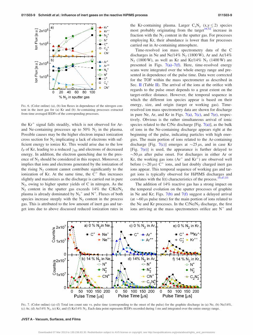
the Krþ signal falls steadily, which is not observed for Ar-
and Ne-containing processes up to 50% N2 in the plasma.
Possible causes may be the higher electron impact ionization
cross section for N2 implicating a lack of electrons with suf-
ficient energy to ionize Kr. This would arise due to the low
IP of Kr, leading to a reduced cSE and electrons of decreased
energy. In addition, the electron quenching due to the pres-
ence of N2 should be considered in this respect. Moreover, it
implies that ions and electrons generated by the ionization of
the rising N2 content cannot contribute significantly to the
ionization of Kr. At the same time, the Cþ flux increases
slightly and maximizes as the discharge is carried out in pure
N2, owing to higher sputter yields of C in nitrogen. As the
N2 content in the sputter gas exceeds 14% the C/Kr/N2
plasma is already dominated by N2þ and Nþ. Fluxes of both
species increase steeply with the N2 content in the process
gas. This is attributed to the low amount of inert gas and tar-
get ions due to above discussed reduced ionization rates in
the Kr-containing plasma. Larger CxNy (x,y� 2) species
most probably originating from the target19,52 increase in
fraction with the N2 content in the sputter gas. For processes
employing Kr, their abundance is lower than for processes
carried out in Ar-containing atmosphere.
Time-resolved ion mass spectrometry data of the C
discharges in Ne and Ne/14% N2 (1800 W), Ar and Ar/14%
N2 (1800 W), as well as Kr and Kr/14% N2 (1400 W) are
presented in Figs. 7(a)–7(f). Here, time-resolved energy
scans were integrated over the whole energy range and pre-
sented in dependence of the pulse time. Data were corrected
for the TOF within the mass spectrometer as described in
Sec. II (Table II). The arrival of the ions at the orifice with
regards to the pulse onset depends to a great extent on the
target-orifice distance. However, the temporal sequence in
which the different ion species appear is based on their
energy, size, and origin (target or working gas). Time-
resolved ion mass spectrometry data are shown for discharge
in pure Ne, Ar, and Kr in Figs. 7(a), 7(c), and 7(e), respec-
tively. Obvious is the rather simultaneous arrival of ionic
species related to the C/Ne discharge [Fig. 7(a)], as the bulk
of ions in the Ne-containing discharge appears right at the
beginning of the pulse, indicating particles with high ener-
gies. The main portion of ions related to the Ar-containing
discharge [Fig. 7(c)] emerges at �25 ls, and in case Kr
[Fig. 7(e)] is used, the appearance is further delayed to
�50 ls after pulse onset. For discharges in either Ar or
Kr, the working gas ions (Arþ and Krþ) are observed well
before (�20 ls) Cþ ions, and last doubly charged inert gas
ions appear. This temporal sequence of working gas and tar-
get ions is typically observed for HiPIMS discharges and
correlates with the I(t) characteristics of the process.19,47,53
The addition of 14% reactive gas has a strong impact on
the temporal evolution on the sputter processes of graphite
in Ne and Kr; Figs. 7(b) and 7(f) suggest a delayed arrival
(at �60 ls pulse time) for the main portion of ions related to
the Ne and Kr processes. In the C/Ne/N2 discharge, the first
ions arriving at the mass spectrometers orifice are Nþ and
FIG. 6. (Color online) (a), (b) Ion fluxes in dependence of the nitrogen con-
tent in the inert gas for (a) Kr and (b) Ar-containing processes extracted
from time averaged IEDFs of the corresponding processes.
FIG. 7. (Color online) (a)–(f) Total ion count rate vs. pulse time (corresponding to the onset of the pulse) for the graphite discharge in (a) Ne, (b) Ne/14%,
(c) Ar, (d) Ar/14% N2, (e) Kr, and (f) Kr/14% N2. Each data point represents IEDFs recorded during 1 ms and integrated over the entire energy range.
011503-9 Schmidt et al.: Influence of inert gases on the reactive HiPIMS process 011503-9
JVST A - Vacuum, Surfaces, and Films
Downloaded 07 Mar 2013 to 130.236.83.30. Redistribution subject to AVS license or copyright; see http://avspublications.org/jvsta/about/rights_and_permissions

N2þ (�50 ls), closely followed by Neþ (�60 ls) and last are
Cþ (�70 ls), Neþþ (�71 ls), together with CNþ (�73 ls).
The first species observed in the reactive discharge employ-
ing Ar and N2 are N2þ (�10 ls) and Arþ (�20 ls) followed
by Nþ (�25 ls) together with Cþ (�30 ls) and, again the
last species arriving are CNþ and Arþþ (both �60 ls). The
temporal evolution of the Kr discharge is much more defined
in the arrival of working gas ions (Krþ isotopes and N2þ at
�35 ls) and ions supposedly originating from the target (Cþ,
Nþ, and Krþþ at �70 ls) and somewhat later after �90 ls
C2þ. An enhanced representation of the temporal evolution
of plasma species of a C/Ar/N2 discharge could be extracted
from time-resolved ion mass spectroscopy with an increased
target-orifice distance of 210 mm.19 Here, the time windows
for working gas ions and ions originating from the target
become more distinct with the applied distance. However, in
order to get a deeper understanding of the particles origin
time-averaged IEDFs should be considered additionally, as
the qualitative comparison of the shape might contain valua-
ble information. In the case of Ne, for example, IEDFs of
Nþ and Cþ show the similar qualitative features. The corre-
sponding time-resolved data show that a considerable por-
tion of Nþ is arriving together with Cþ. It is thus reasonable
to assume that this fraction of Nþ originates from a nitrogen
passivated graphite target surface.
C. Impact of inert gases on a-C and CNx film growthand microstructure
As was demonstrated in Sec. III B, processes employing
different inert gases differ to a great extent in particle
energy, the amount of Cþ, Nþ, N2þ, and inert gas ions as
well as in the amount of so-called structure-defining CxNyþ
species. This implies effects on the film growth and the
microstructure of a-C and CNx thin films, which will be
addressed in this section.
In Fig. 8, the deposition rates of a-C (solid square) and
CNx (open triangle) are shown for the three different inert
gases as obtained from the ratio of the film thickness (by
cross-sectional SEM) and the deposition time. Evident are
the low deposition rates for films deposited with HiPIMS in
pure Ne and Ne/14% N2, compared to those of Ar. Consider-
ing the comparatively high sputter yield of C in Ne, the dep-
osition rates should be higher. However, the high ion count
rates for the corresponding Ne processes suggest that more
material is lost by their back attraction.54 Moreover,
Cþ, Neþ, and Nþ energies in Ne-containing processes [cf.
Figs. 3(a), 3(b), and 3(f), gray and black lines, 14% and 0%
N2 in the sputter gas] are 10–12 times higher than those
recorded for Ar. This, in combination with the bias voltage
of �100 V, which was set for all depositions, increases the
energy of ions impinging on the substrate further. Therefore,
the physical resputter processes at the substrate may occur to
much higher extent in case the graphite target is sputtered in
Ne and Ne/14% N2 atmosphere compared to the correspond-
ing Ar- and Kr-sputter processes. The deposition carried
out in pure Kr atmosphere showed a similar rate as the corre-
sponding Ar process. Also, the reactive process in Kr/N2
yielded a comparatively low deposition rate. This agrees
with similar C sputter yields of C in Kr and Ar.55
Moreover, Fig. 8 presents the nitrogen content of the CNx
films for Ne, Ar, and Kr as obtained by ERDA. Obvious is
the elevated N content of �19 at. % in the CNx film depos-
ited in Ne/N2 atmosphere. The combination of efficient N2
dissociation and ionization, and N species of high energy
lead to an increased amount of incorporated N. The effect of
high particle energies was also observed in ERDA depth pro-
files (not shown here), as a three times broader substrate/thin
film interface was found for the CNx thin film deposited in
Ne compared to that produced in Kr-containing atmosphere.
This intermixing of the materials is caused by high particle
energies. The CNx deposition in Kr yields �13 at. % N in
the films. This is considered to be a consequence of the
reduced N2 dissociation and ionization in the Kr/14% N2
plasma. Here, lowered total and relative contents of CNþ
ions as well as Nþ ions were found, indicating decreased
amounts of CxNy species and dissociated N2 in the plasma.
These species are understood to be key components for the
incorporation of nitrogen into the film.
Figure 9 comprises N1s core level photoelectron spectra
of CNx thin films deposited at 430 �C with 14% N2 in Kr, Ar,
or Ne. A maximum number of four contributions (C1–C4)
were fitted into the N1s spectra. The main contributions, C1
(�400.5 eV) and C2 (398.1–398.6 eV), are assigned to nitro-
gen substitutional bonded in a 3-fold coordinated C-network
(e.g., N bonded into a sp2-coordinated carbon plane) and
a sp2-hybridized nitrogen bonded with two bonds to the
C-network (pyridine-like), respectively.56,57 The bonding
configuration associated with C2 arises next to defects or at
the periphery of the graphene sheets, breaking their continu-
ity. As indicated in Fig. 9, the C1/C2 increases with decreas-
ing amount of incorporated N in the film (values for [N] at
430 �C are given in Fig. 9) and increasing inert gas mass. C1/
C2 is greater than one for Ar- and Kr-containing processes.
The structural arrangement of thin films is correlated to the
C1/C2 ratio.56 Increased C1/C2 ratios indicate a pronounced
fullerene-like structural evolution, since C1 (�400.5 eV) is
attributed to N substitutionally bonded in extended carbon
sheets, while C2 (�398.2 eV) is attributed to N bonded along
edges and defects.56,57 For CNx thin films deposited in either
FIG. 8. Deposition rates (Rd) for nonreactive (filled squares) and reactive
processes (14% N2, open triangles) as obtained from the ratio of film thick-
ness and deposition time as well as the N nitrogen contents ([N]) of CNx
thin films deposited at a substrate temperature of 110 �C in Ne, Ar, and Kr.
011503-10 Schmidt et al.: Influence of inert gases on the reactive HiPIMS process 011503-10
J. Vac. Sci. Technol. A, Vol. 31, No. 1, Jan/Feb 2013
Downloaded 07 Mar 2013 to 130.236.83.30. Redistribution subject to AVS license or copyright; see http://avspublications.org/jvsta/about/rights_and_permissions

Kr- or Ar-containing atmosphere, the C1/C2 ratios are higher
than 1, indicating that both CNx films exhibit a FL-structure.
This is conceivable as both processes showed low ion ener-
gies (cf. Sec. III B) preserving structure-defining CxNy-spe-
cies (x, y� 2) in the plasma, which in turn promote the
chemical desorption processes at the substrate. Especially,
the Kr process was governed by low energy ions, which is
mirrored in the comparably high C1/C2 ratio of 1.47. In con-
trast to the high C1/C2 ratio observed for CNx obtained in
Kr-containing atmosphere, C1 and C2 appear broadened,
additionally, C2 shifts toward higher binding energies. Both
usually imply amorphous structures and were observed in
thin films deposited at temperatures below 300 �C.56
The deposition of CNx thin films in Ne-containing atmos-
phere yields C1/C2< 1, indicating an amorphous structure
with frequently disrupted graphene sheets. This correlates
with IEDFs recorded for the C/Ne/14% N2 plasma consisting
mainly of ions exhibiting high energies, which in turn are
likely to destroy a structural evolution of the thin films. The
assignment of C3, a minor contribution arising between
403 eV and 402 eV, is not consistent in literature. C3 is
reported to arise either from N-O (Ref. 11) bonds or due to a
similar substitutional bonding configuration as described for
C1, except that the nitrogen donates an electron to the struc-
ture; thus, the C3 peak appears at higher binding energies
and scales with C1.11,57 C4 (�399 eV) is assigned to sp-
hybridized nitrogen in a nitrile57 structure. Only for CNx thin
films deposited in Ne-containing atmosphere C4 could be fit-
ted. This correlates with high amounts of incorporated N
into the film.
Figures 10(a)–10(c) show selected HRTEM images with
corresponding SAED patterns from the samples analyzed by
XPS and presented in Fig. 9. The comparison of the relative
intensities of diffuse SEAD rings provides information about
the degree and extension of the graphitic short range order of
CNx films.41 The peak intensity ratio I3.5 A/I2 A (R) provides
a parameter for the quantitative comparison of the micro-
structure. The evaluation of SAED pattern revealed R to be
highest (>1) for CNx thin films deposited in Ar (R� 2) and
Kr (R� 1) and R< 1 for CNx when Ne (R� 0) was
employed as sputter gas. The results extracted from the
SAED pattern are also reflected in the corresponding
HRTEM images, as these reveal a FL structure for thin films
sputtered in Ar- [Fig. 10(b)] or Kr-containing atmosphere
[Fig. 10(c)] and an amorphous thin film for the CNx thin film
produced in Ne/N2 [Fig. 10(a)].
The relative intensity of the �3.5 A peak correlates with
the C1/C2 ratio of the XPS N1s regions as observed for DC
sputtered CNx films.56 However, the correlation is not satis-
factory, if merely the XPS C1/C2 ratio is taken into account,
since CNx films deposited in Ar/14% N2 seem to posses a
more pronounced fullerene-like structure by HRTEM and
SAED (R� 2) than that deposited in Kr/14% N2 (R� 1),
although the C1/C2 ratio for the thin film deposited in Kr-
containing atmosphere is higher. Thus, as pointed out above,
the peak broadening of C1 and C2 as well as the shift of C2
toward higher binding energies for the 14% N2/Kr process
should also be taken into account, as both are signs of a less
ordered structure.57
FIG. 9. (Color online) XPS N1s spectra of CNx thin films deposited using
reactive HiPIMS and a substrate temperature of 430 �C in Ne, Ar, and Kr
containing 14% N2. The peak deconvolution, the N content in the CNx thin
films, and the C1/C2 ratios of the corresponding films are indicated.
FIG. 10. (a)–(c) Cross-sectional HRTEM images with corresponding SAED patterns from CNx thin films deposited by HiPIMS at TS¼ 430 �C in 14% N2 and
different inert gases: (a) 14% N2/Ne, (b) 14% N2/Ar, and (c) 14% N2/Kr. SAED labels in (c) mark the position of �1.15 and �2.1 A diffuse rings. The arrow
indicates the brightest segment of the �3.5 A ring, which implies a slightly textured graphitic ordering (with preferred orientation of basal planes perpendicular
to the substrate). The growth direction in the HRTEM images shows upwards. The films deposited in Ar and Kr have the most pronounced fullerene-like
structure.
011503-11 Schmidt et al.: Influence of inert gases on the reactive HiPIMS process 011503-11
JVST A - Vacuum, Surfaces, and Films
Downloaded 07 Mar 2013 to 130.236.83.30. Redistribution subject to AVS license or copyright; see http://avspublications.org/jvsta/about/rights_and_permissions

IV. CONCLUSIONS
Reactive HiPIMS of C in the inert gases Ne, Ar, and Kr
yield distinctly different discharges. The I(t) discharge char-
acteristics of the inert gases show increasing target currents
with decreasing atomic number, mainly caused by different
IP as well as ionization pathways and cross sections. The
most abundant precursors in reactive processes are Cþ, Nþ,
N2þ, single and double charged inert gas ions, and to a lower
extent CNþ. The IEDFs of the corresponding discharges
when no N2 is involved exhibit increasing energies with
decreasing atomic number of the inert gas. When the N2 con-
tent of the C/Ne-HiPIMS discharge exceeds 14%, the energy
of Cþ, Neþ, and Nþ decreases significantly, since Penning
ionization of N2 disappears gradually for increasing N2 con-
centrations in the working gas. When N2 is added to the Ar
and Kr processes, the energy of the IEDFs increases with
increasing N2 content in the sputter gas. However, Ne- and
Kr-containing discharges are more affected by the reactive
gas than it is the case for Ar. This can be attributed to much
higher differences in IP and the total ionization cross sections
for Ne and Kr with regards to N2 and N than for Ar. The total
amount of ions increases in the sequence Kr, Ar, and Ne
because of the increasing ionization potential that causes a
higher electron temperature of the corresponding plasma and
thus, an improved ionization. Additionally, the energy of
metastable states increases in the same sequence, which
allows only Ne to Penning ionize and excite N2, implicating
its highly efficient dissociation. This is mirrored in the
amplified abundance of CxNy species (x,y� 2) of the Ne-
containing plasma above 33% N2 in the gas. The relative,
but not the total Cþ ion flux is highest in case the graphite
target is sputtered in pure Ar, followed by Ne and Kr. Inde-
pendent from the inert gas, the relative Cþ flux decreases in
reactive sputter mode and shows a minimum between 33%
and 50% of N2 in the plasma, in consequence of increasing
Nþ and N2þ fluxes. The relative fluxes of Nþ increase with
decreasing atomic number of the inert gas, while the relative
flux of N2þ shows the opposite trend owing to the increased
ability of Ne to dissociate N2. The deposition rates are high-
est as C is sputtered in Kr- or Ar-containing atmosphere,
while processes in Ne yield the lowest deposition rates,
which we attribute to back attraction and to physical resput-
tering due to the high amount and energy of the particles
arriving at the substrate. Reactive processes with 14% N2 in
either Ne or Ar yield increased deposition rates, whereas
similar deposition rates were found for reactive and nonreac-
tive processes involving Kr. The amount of incorporated N
in the CNx thin films is highest for Ne-containing processes,
which is attributed to a combination of efficient N2 dissocia-
tion and ionization, and N species of high energy that lead to
an increased probability for incorporated N in a pyridine-
and nitrile-like manner. We also find a relative increase of
substitutional bonded nitrogen in a 3-fold coordinated C net-
work with atomic number of the inert gas, accounting for a
pronounced FL-structure of the thin film. This is also mir-
rored in TEM and SAED results; amorphous CNx thin films
were obtained for the process with Ne/14% N2, whereas gas
mixtures involving Ar/14% N2 or Kr/14% N2 yielded FL-
CNx thin films. Ion mass spectrometry, XPS, and TEM
results emphasize the crucial role of low particle energies
generated in the plasma and N-containing precursor species
(CxNy) for the structural evolution of CNx thin films.
ACKNOWLEDGMENTS
An ERC Advanced Grant and the VINN Excellence Center
Functional Nanoscale Materials (FunMat) are acknowledged.
With regards to ERDA measurements, the authors are thankful
for the access to the Tandem Laboratory, Uppsala University.
Zsolt Czig�any acknowledges the Bolyai Scholarship of the
Hungarian Academy of Sciences.
1Y. Lifshitz, Diam. Relat. Mater. 5, 388 (1996).2J. Robertson, Phys. Rev. Lett. 68, 220 (1992).3J. Robertson, Jpn. J. Appl. Phys. 50, 8 (2011).4N. Hellgren, M. P. Johansson, B. Hjorvarsson, E. Broitman, M. Ostblom,
B. Liedberg, L. Hultman, and J. E. Sundgren, J. Vac. Sci. Technol. A 18,
2349 (2000).5J. Neidhardt and L. Hultman, J. Vac. Sci. Technol. A 25, 633 (2007).6J. C. Angus and C. C. Hayman, Science 241, 913 (1988).7J. Robertson, Adv. Phys. 35, 317 (1986).8J. Robertson, Mater. Sci. Eng. R 37, 129 (2002).9A. Grill, Diam. Relat. Mater. 12, 166 (2003).
10J. Neidhardt, L. Hultman, E. Broitman, T. W. Scharf, and I. L. Singer,
Diam. Relat. Mater. 13, 1882 (2004).11L. Hultman, J. Neidhardt, N. Hellgren, H. Sjostrom, and J. E. Sundgren,
MRS Bull. 28, 194 (2003).12M. C. Polo, J. L. Andujar, A. Hart, J. Robertson, and W. I. Milne, Diam.
Relat. Mater. 9, 663 (2000).13J. Robertson, Prog. Solid State Chem. 21, 199 (1991).14Y. Lifshitz, S. R. Kasi, J. W. Rabalais, and W. Eckstein, Phys. Rev. B 41,
10468 (1990).15P. J. Fallon, V. S. Veerasamy, C. A. Davis, J. Robertson, G. A. J. Amara-
tunga, W. I. Milne, and J. Koskinen, Phys. Rev. B 48, 4777 (1993).16J. Robertson, Diam. Relat. Mater. 2, 984 (1993).17J. T. Gudmundsson, N. Brenning, D. Lundin, and U. Helmersson, J. Vac.
Sci. Technol. A 30, 030801 (2012).18U. Helmersson, M. Lattemann, J. Bohlmark, A. P. Ehiasarian, and J. T.
Gudmundsson, Thin Solid Films 513, 124 (2006).19S. Schmidt, Z. Czigany, G. Greczynski, J. Jensen, and L. Hultman,
J. Appl. Phys. 112, 013305-11 (2012).20B. M. DeKoven, P. R. Ward, R. E. Weiss, D. J. Christie, R. A. Scholl,
W. D. Sproul, F. Tomasel, and A. Anders, in 46th Annual TechnicalConference Proceedings, San Francisco, CA (Society of Vacuum Coaters,
2003), pp. 158–165.21K. Sarakinos, A. Braun, C. Zilkens, S. Mraz, J. M. Schneider, H. Zoubos,
and P. Patsalas, Surf. Coat. Technol. 206, 2706 (2012).22I. Petrov, L. Ivanov, V. Orlinov, J. Kourtev, and J. Jelev, Thin Solid Films
185, 247 (1990).23A. Aijaz, K. Sarakinos, D. Lundin, N. Brenning, and U. Helmersson,
Diam. Relat. Mater. 23, 1 (2012).24K. J. Taylor, S. M. Yun, and G. R. Tynan, J. Vac. Sci. Technol. A 22,
2131 (2004).25K. Ohya, Nucl. Instrum. Meth. Phys. Res. B 206, 52 (2003).26J. C. Avelar-Batista, A. D. Wilson, A. Davison, A. Leyland, A. Matthews,
and K. S. Fancey, Thin Solid Films 398–399, 507 (2001).27F. M. Penning and C. C. J. Addink, Physica 1, 1007 (1934).28K. S. Fancey, Vacuum 46, 695 (1995).29J. Nagai, J. C. Thomaz, J. Amorim, and G. Baravian, Eur. Phys. J. 26, 53
(2004).30G. K. Gueorguiev, J. Neidhardt, S. Stafstrom, and L. Hultman, Chem.
Phys. Lett. 410, 228 (2005).31M. Schlueter, C. Hopf, and W. Jacob, New J. Phys. 10, 053037 (2008).32J. Bohlmark, M. Lattemann, J. T. Gudmundsson, A. P. Ehiasarian, Y. A.
Gonzalvo, N. Brenning, and U. Helmersson, Thin Solid Films 515, 1522
(2006).
011503-12 Schmidt et al.: Influence of inert gases on the reactive HiPIMS process 011503-12
J. Vac. Sci. Technol. A, Vol. 31, No. 1, Jan/Feb 2013
Downloaded 07 Mar 2013 to 130.236.83.30. Redistribution subject to AVS license or copyright; see http://avspublications.org/jvsta/about/rights_and_permissions
33N. Hellgren, M. P. Johansson, E. Broitman, L. Hultman, and J.-E. Sundg-
ren, Phys. Rev. B 59, 5162 (1999).34N. Hellgren, M. P. Johansson, E. Broitman, P. Sandstrom, L. Hultman,
and J. E. Sundgren, Thin Solid Films 382, 146 (2001).35H. J. Whitlow, G. Possnert, and C. S. Petersson, Nucl. Instrum. Meth.
Phys. Res. B 27, 448 (1987).36J. Jensen, D. Martin, A. Surpi, and T. Kubart, Nucl. Instrum. Meth. Phys.
Res. B 268, 1893 (2010).37Z. Czigany, J. Neidhardt, I. F. Brunell, and L. Hultman, Ultramicroscopy
94, 163 (2003).38E. Broitman, N. Hellgren, J. Neidhardt, I. Brunell, and L. Hultman,
J. Electron. Mater. 31, L11 (2002).39J. P. McCaffrey, Microsc. Res. Techn. 24, 180 (1993).40J. L. Labar, Microsc. Microanal. 15, 20 (2009).41Z. Czigany and L. Hultman, Ultramicroscopy 110, 815 (2010).42D. Rapp and P. Englander-Golden, J. Chem. Phys. 43, 1464 (1965).43D. M. Mattox, Handbook of Physical Vapor Deposition (PVD) Processing
(Noyes, Park Ridge, NJ, 1998).44A. Anders, Surf. Coat. Technol. 205, S1 (2011).45J. T. Gudmundsson, J. Alami, and U. Helmersson, Surf. Coat. Technol.
161, 249 (2002).46A. Hecimovic and A. P. Ehiasarian, IEEE Trans. Plasma Sci. 39, 1154
(2011).
47M. Hala, N. Viau, O. Zabeida, J. E. Klemberg-Sapieha, and L. Martinu,
J. Appl. Phys. 107, 9 (2010).48G. Lemp�eriere and J. M. Poitevin, Vacuum 37, 825 (1987).49A. Hecimovic, K. Burcalova, and A. P. Ehiasarian, J. Phys. D 41, 10 (2008).50N. Itagaki, S. Iwata, K. Muta, A. Yonesu, S. Kawakami, N. Ishii, and
Y. Kawai, Thin Solid Films 435, 259 (2003).51S. Yoon and W. L. Glab, J. Phys. B 27, 4133 (1994).52J. Neidhardt, L. Hultman, B. Abendroth, R. Gago, and W. Moller, J. Appl.
Phys. 94, 7059 (2003).53G. Greczynski and L. Hultman, Vacuum 84, 1159 (2010).54N. Brenning, C. Huo, D. Lundin, M. A. Raadu, C. Vitelaru, G. D. Stancu,
T. Minea, and U. Helmersson, Plasma Sources Sci. Technol. 21, 025005
(2012).55E. Oyarzabal, R. P. Doerner, M. Shimada, and G. R. Tynan, J. Appl. Phys.
104, 043305 (2008).56J. Neidhardt, L. Hultman, and Z. Czigany, Carbon 42, 2729 (2004).57N. Hellgren, J. H. Guo, Y. Luo, C. Sathe, A. Agui, S. Kashtanov,
J. Nordgren, H. Agren, and J. E. Sundgren, Thin Solid Films 471, 19
(2005).58R. Rejoub, B. G. Lindsay, and R. F. Stebbings, Phys. Rev. A 65, 042713
(2002).59Y.-K. Kim and J.-P. Desclaux, Phys. Rev. A 66, 012708 (2002).60J. F. Ziegler, http://www.srim.org/, v. srim 2008 (November 2012).
011503-13 Schmidt et al.: Influence of inert gases on the reactive HiPIMS process 011503-13
JVST A - Vacuum, Surfaces, and Films
Downloaded 07 Mar 2013 to 130.236.83.30. Redistribution subject to AVS license or copyright; see http://avspublications.org/jvsta/about/rights_and_permissions