iass2010 lachauer rippmann block
TRANSCRIPT

Proceedings of the International Association for Shell and Spatial Structures (IASS) Symposium 2010, Shanghai
Spatial Structures – Permanent and Temporary
November 8-12 2010, Shanghai, China
Form Finding to Fabrication:
A digital design process for masonry vaults
Lorenz LACHAUER1*, Matthias RIPPMANN
1, Philippe BLOCK
2
1*Research Assistant, Institute of Technology in Architecture, ETH Zurich
Wolfgang-Pauli-Strasse 15, HIL E 43.2
8093 Zurich, SWITZERLAND
2Assistant Professor, Institute of Technology in Architecture, ETH Zurich
Abstract
It is common practice in engineering to represent a continuous stress field by a
network of discrete forces, e.g. hanging models (Gaudí), cable nets (Otto) or strut-and-
tie models (Schlaich) . These discrete force networks allow the user to visualize, grasp
and control the flow of forces in an intuitive manner. A recent computational advance in
this field is Thrust Network Analysis (TNA), which allows form finding controlled
through discrete force diagrams.
In this paper, a fully digital design process –from form finding to fabrication– for
compression-only masonry shells will be presented. The challenge is to provide a
smooth and efficient generation of different data representations of the discrete
geometry of the force (or thrust) network for the use in structural and experimental
modelling, discrete element modelling (DEM) software, or fabrication. The TNA
method has been implemented in existing CAD software, offering fully interactive
control of the boundary conditions, the internal stress field and the weight distribution
of the shell. The discrete thrust network is linked to a NURBS surface to derive
continuous geometric information, hence allowing the automatic generation of the shell
volume according to its self weight.
Keywords: digital workflow, form-finding, parametric modelling, masonry vault design, fabrication
1 Introduction
The direct integration of structural constraints in the design process using physical
models has a long tradition. In 1908, Antoni Gaudí finished a sophisticated hanging
model for the design of the Colonia Güell church [1]. In 1964, Frei Otto founded the
Institute of Lightweight Structures (IL) at the University of Stuttgart, where the use of
physical models in structural design has been studied systematically [2]. A first
application of these model-based design processes for shell design from the IL has been
the building Multihalle Mannheim in 1975.
In contrast to Otto, the Swiss engineer Heinz Isler used since the 1950s a model-based
workflow not for lightweight structures, but for thin concrete shell design. Isler worked
Proceedings of the International Association for Shell and Spatial Structures (IASS) Symposium 2010, Shanghai
Spatial Structures – Permanent and Temporary
November 8-12 2010, Shanghai, China
not only on the form finding, but also on the in-depth optimization of a continuous
design-analysis-construction process based on physical models. For the design phase,
Isler used inverted hanging cloth models, hardened with plaster or polyester resin,
which then were tested with electronic strain gauges to measures the shell behaviour
under applied load. Finally, the geometry was carefully measured by a mechanical,
three-dimensional measurement device, which traced the profiles used for the
scaffolding plans [3].
Today, in the age of computer aided design and manufacturing, the concept of the
continuous digital chain has been introduced for architectural design [4]. The
integration of geometric and fabrication constraints in a digital workflow has been
shown for timber construction [5]. Recently, the integration of structural constraints in a
design process using a digital simulation of hanging models and linking them to
fabrication has been demonstrated [6].
The use of simulations and computational tools, instead of physical models and
mechanical tools, causes a shift in the problem. While Isler mainly had to overcome
inaccuracies in the modelling process and the material testing, the challenges today are
in data processing, as each part of the process (e.g. form finding, structural analysis, and
manufacturing) uses different data representations, and each conversion of data is
typically causing a loss of information or accuracy.
2 Setup of Digital Design and Fabrication Processes for Vaults
This paper describes a continuous digital design workflow for masonry vaults, based on
the form-finding technique Thrust Network Analysis (TNA) [7, 8]. This method allows
the design of compression-only networks based on discrete force diagrams. The
resulting equilibrium networks are the control geometry of continuous NURBS surfaces
[9] which are used for the generation of stone block geometries, analysis data, and
fabrication and construction information. In order to process these different data
representations, commercial software packages and CAD programs are used, connected
and extended via custom developed interfaces to increase the software’s capabilities.
The sophisticated, but well-defined task of shell design allows the setup of a
tight prototypical computational workflow in vitro. The paradigm for this approach is
the work of Heinz Isler, who developed a tight design process for shells based on
physical models. The consistent integration of design information with geometric data,
presented in this paper, may be interpreted as project-specific Building Information
Modelling (BIM) [10].
Section 3 describes how different data transitions via custom tools and interfaces are
managed in detail. In section 4, a design-to-fabrication chain for structural models
using rapid prototyping (3D printing), is demonstrated. It will be shown that this process
is very close to a process that might be used for the actual goal of designing large-scale
stone masonry vaults.
Proceedings of the International Association for Shell and Spatial Structures (IASS) Symposium 2010, Shanghai
Spatial Structures – Permanent and Temporary
November 8-12 2010, Shanghai, China
3 Customized Linking of Data and Applications
This chapter describes in detail strategies for the setup of a digital workflow for
computational vault design and realization. In order to efficiently deal with the diverse
challenges of form finding, analysis, and fabrication, commercial software packages are
linked with applications that were developed for this research project. The link between
these different programs is established by custom-made software interfaces. These
interfaces provide a structured transition between different data representations of
geometry and structural properties. The use of build-in import/export routines instead of
custom interfaces would cause a loss of geometrical and structural information.
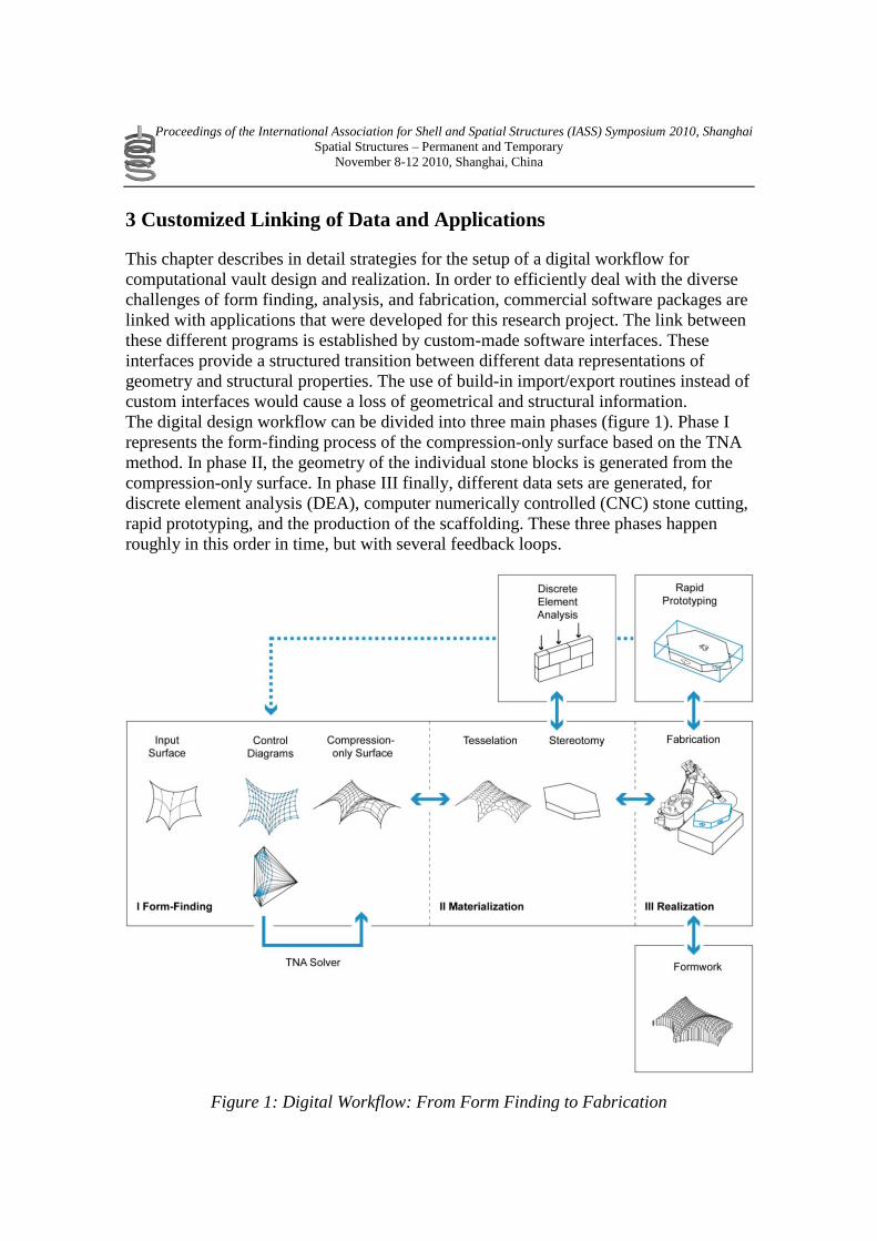
The digital design workflow can be divided into three main phases (figure 1). Phase I
represents the form-finding process of the compression-only surface based on the TNA
method. In phase II, the geometry of the individual stone blocks is generated from the
compression-only surface. In phase III finally, different data sets are generated, for
discrete element analysis (DEA), computer numerically controlled (CNC) stone cutting,
rapid prototyping, and the production of the scaffolding. These three phases happen
roughly in this order in time, but with several feedback loops.
Figure 1: Digital Workflow: From Form Finding to Fabrication
Proceedings of the International Association for Shell and Spatial Structures (IASS) Symposium 2010, Shanghai
Spatial Structures – Permanent and Temporary
November 8-12 2010, Shanghai, China
3.1 Phase I: Form Finding
Thrust Network Analysis (TNA) uses projective geometry, reciprocal diagrams and
linear optimization to provide a graphical, intuitive and real-time method, adopting the
same advantages of techniques such as graphic statics [11], but offering a viable
extension to fully three-dimensional problems.
(a) Input surface
The first step defines the general outline of the shell structure in plan. It is represented
by a single or poly surface (using NURBS surfaces) in a NURBS-modeling
environment, such as McNeel’s Rhinoceros® [12]. Both CAD applications feature tools
to easily generate and manipulate the form-determining surface. Further customized
tools were developed to make the process of manipulation more intuitive for the user.
(b) Control Diagrams
By addressing the input surface’s local coordinate systems the planar force network,
representing possible force lines in the structure, is generated automatically. This
process is fully integrated in the CAD environment interactively responding to any
changes made on the input surface. “Stitching” different NURBS surfaces, with each
their internal force pattern logic, allows the generation of sophisticated force line
topologies.
Based on the nodes and branches of the planar force network the reciprocal force
diagram is produced according to Maxwell’s definition of reciprocal figures [13]
through two consecutive linear optimization procedures [8]. The reciprocal diagram,
visualizing the proportional relationship of horizontal forces in the network, can then be
interactively manipulated by the user in order to vary the shape of the shell structure.
The process of manipulating the grids is fully integrated into a live feedback-loop
allowing for visual control of the resulting geometry in real-time.
(c) Compression-only surface
The output of this interactive form finding, which mediates between structural, visual
and functional needs, is provided as a single or poly NURBS surface automatically
generated from the point set data of the TNA. The TNA solver is integrated by
implementing the matrix computation routines from Rhino SDK [14] in custom-made
Grasshopper vb.net nodes [15] and by calling MatLab executables [16] from
RhinoScripts [17]. All information about the grid topology is maintained by addressing
the corresponding local coordinates of the thrust surface that represents the ideal shape
for the compression-only shell geometry according to the given input parameters.
Therefore, all data can be extracted and processed smoothly for the further phases of the
design process.
2.2 Phase II: Materialization
The resulting thrust surface of the first phase represents an ideal compression-only form
for a given, dominant loading case (which is also definable by the user), but is not yet

Proceedings of the International Association for Shell and Spatial Structures (IASS) Symposium 2010, Shanghai
Spatial Structures – Permanent and Temporary
November 8-12 2010, Shanghai, China
influenced or driven by constraints arising from fabrication and construction techniques
as well as material properties. For the surface’s physical representation further
constraints have to be taken into account. The following steps are based on the
realization of the shell’s physical scale model.
This paper particularly describes the process of designing vaulted masonry-like
structures. The way of tessellating the surface is of key importance for the further
process. The tessellation of the geometry is influenced by the general shape of the
surface, linked to the design intent, its visual appearance (tectonics), the structural
analysis (force flow) and of course fabrication and material properties. The inter-
dependency of these parameters led to an approach that allows visual feedback and
multiple ways of controlling the process.
(a) Tessellation
First, a 2D topology for the given surface is defined, primarily depending on the number
and proportion of open and closed edges and the number of supports (Fig. 2). This
pattern is represented visually by a 2D polyline formation that can either be generated
by the user or by mathematic algorithms for ruled based configurations.
Using relaxation procedures, based on the transient stiffness method [18], which are
tightly integrated in the general digital workflow, the pattern is distributed evenly on the
surface. This approach allows to computationally control the edge conditions. In
contrast to e.g. pulling or projecting a pattern onto a surface, which typically results in
problems, or special cases, at the borders and corners of the surface patch to be
tessellated, this approach solves all these issues, connecting this step nicely to the
smooth digital workflow. Figure 2 shows the relation of the 2D pattern and the
corresponding surface boundary for different plan geometries.
Figure 2: 2D patterns for different surface (edge) geometries.
During the iterative process of distributing the pattern evenly on the surface, all vertices
stay on the surface (Fig. 3). Certain vertices are fixed at supports (the heavier dots in
Fig. 2) and edge vertices are constrained to only move along the surface edge.

Proceedings of the International Association for Shell and Spatial Structures (IASS) Symposium 2010, Shanghai
Spatial Structures – Permanent and Temporary
November 8-12 2010, Shanghai, China
Figure 3: (a) Start configuration and relaxed pattern after (b) 5 and (c) 200 iterations.
The relaxation procedure can further be informed by restrictions arising from the force
distribution, the need for interlocking or staggered tessellation and fabrication
constraints like material and tooling properties (e.g. compression strength , friction,
size, maximum weight per piece or planar cutting planes). One way to incorporate those
requirements is to generate specific guides addressing the aforementioned aspects. For
example, as shown in Figure 4, certain groups of vertices can be forced to move only
along provided lines, which e.g. result from a surface analysis of the structural thrust
surface. Such additional constraints result in more control of the 3D pattern.
Figure 4: (a) Start configuration and relaxed pattern after (b) 5 and (c) 200 iterations
with control guides.
(b) Stereotomy
Based on the tessellation pattern, individual blocks are generated using a custom
RhinoScript routine. The NURBS surface provides the geometric information of the
surface normals; the load assumptions, used for form finding, determine the depth of the
blocks. The block interface surfaces, generated by this routine, are double curved, which
is no problem for 3D printing. In order to build the vault from stone blocks, further
research has to be done to simplify the geometry of the stone blocks. Planar interface
surfaces e.g. would be significantly more efficient for stone cutting. For the model,
additional block geometry modifications have been implemented, such as the
application of notches and numbers.
Proceedings of the International Association for Shell and Spatial Structures (IASS) Symposium 2010, Shanghai
Spatial Structures – Permanent and Temporary
November 8-12 2010, Shanghai, China
2.3 Phase III: Realization
In the realization phase, different data sets are produced from the compression-only
surface and the block geometries for the purpose of analysis, model production,
fabrication, and assembly.
(a) Discreet Element Analysis
Discreet Element Analysis (DEA) is a method originally developed for rock mechanics.
It is used for computational testing of the mechanical behaviour of discreet elements.
Recent approaches show the application of DEA for masonry structures [19]. The
commercial package 3DEC [20] used in this research works with convex polyhedra as
input. To generate the input data, the stone block geometries have to be subdivided in
convex polyhedra. In a second step they have to be exported in the specific data format
used by the software package. Both steps are implemented as software applets for
Rhinoceros using RhinoScript.
(b) Rapid Prototyping
Rapid Prototyping is used to produce structural models for physical testing. Several
routines were developed for labelling and registration of the pieces. Further post-
processing routines for the optimization of the 3D-printing time, material and cost have
been programmed (Fig. 6).
(c) Fabrication
For the fabrication of the individual stone blocks, in a first step, the pieces have to be
aligned automatically, so that the cut-off is minimized. Then the fabrication data has to
be produced from the block geometry, so that the CNC machine is cutting the stone in
an efficient way, reducing cutting time and therewith cost.
(d) Formwork
Formwork has to be built to assemble the real-scale shell. Software routines have to be
developed, to generate efficient geometry of these structures automatically. The
formwork is a huge expense factor for building shells, so the focus in the optimization
of the scaffolding geometry should be on cost reduction.
4 Application: Structural Model Building
This section describes the production and assembly of a structural model as an
application of the digital process described in the previous section: a masonry vault,
built from individually cut stone blocks. In the scale model, each stone is represented by
a piece of 3D-printed resin. The design, production, assembly, and structural behaviour
of the scale model have analogies to the design, fabrication, building, and behaviour of
the real masonry-like vault. These analogies allow the anticipation of challenges in the
planning and construction process of the real scale vault while building the structural
model. Some strategies and software tools, developed for the rationalization of the

Proceedings of the International Association for Shell and Spatial Structures (IASS) Symposium 2010, Shanghai
Spatial Structures – Permanent and Temporary
November 8-12 2010, Shanghai, China
model planning, can be directly used in the fabrication process of the real vault.
Analogies between scale model and real building are the followings:
4.1 Structural Behaviour
The form of the vault and the geometry of the individual stone blocks is designed, such
that the vault stands without any mortar, just by friction between the blocks. This is
possible, because of the existence of a compression-only force pattern, generated with
TNA. The structural behaviour of such a shell structure is invariant to scaling, as long as
the blocks have sufficient friction [21]. This invariance in scale allows the building of a
scale model with the same structural behaviour like the real vault from any not
deformable modelling material.
4.2 Logistics and Labelling
Models often consist of hundreds of pieces. To assemble them, a labelling system has
been introduced, which allows the identification of a given model piece in the CAD
model. Therefore a custom software applet has been developed using RhinoScript, that
automatically marks the pieces in the digital model. The numbering is related to the
order/sequence of assembly. The labels appear as “stamps” in the 3D-printed pieces
(Fig. 5). In the real stone vault, one has to deal with similar problems of logistics and
labelling. First, a sequence of construction has to be developed. The labelling system of
the stone blocks has to represent construction sequence, position, and orientation of
each block in the shell.
4.3 Minimization of Material
Before starting the rapid prototyping process, an important pre-processing step is the
alignment of the pieces in the CAD program. A dense packing of the pieces enables a
significant reduction of the resin amount, production time, and cost of the model. A
custom-made software applet has been developed in order to arrange the pieces
automatically. A first routine computes the minimal bounding box of each piece, and
then horizontally aligns them. A second routine nests the pieces in a box representing
the building space of the rapid prototyping machine (Fig. 5). For the fabrication of the
real scale stone blocks, the automatic alignment according to the minimal bounding box
minimizes the cut-off of stone material.

Proceedings of the International Association for Shell and Spatial Structures (IASS) Symposium 2010, Shanghai
Spatial Structures – Permanent and Temporary
November 8-12 2010, Shanghai, China
Figure 5: Nesting for rapid prototyping
4.4 Formwork
Instead of assembling the model pieces using formwork in model scale, the pieces are
assembled upside-down in a bowl-like negative form of the shell. This negative form, or
cradle, is cut out from a foam block with a 3 axis CNC mill. For proper registration of
the pieces in the cradle, a system of notches has been developed. They were
automatically generated in the digital model by a custom script (Fig. 6). After arranging
all pieces in the cradle, the base plate with slots at the supports is placed on top of the
foam block. Then, the whole package of cradle, base plate and pieces are flipped.
Finally, the cradle is removed and the model stands just by friction between the pieces.
For the building process of the stone vault, scaffolding has to be developed. Based on
the same surface information as the cradle, a process for the automated generation of
scaffolding geometry and then fabrication data has to be set up.

Proceedings of the International Association for Shell and Spatial Structures (IASS) Symposium 2010, Shanghai
Spatial Structures – Permanent and Temporary
November 8-12 2010, Shanghai, China
Figure 6: Cradle, model setup and assembly.
5 Conclusions and Outlook
This paper has described a powerful, interactive process for designing structural,
masonry-like vaults. A smooth digital workflow has been developed, going from form
finding to fabrication, dealing with a variety of constraints. The form finding is based
on TNA, which uses discrete control and force diagrams, to explore structural form.
These discrete networks are directly the control framework for NURBS surfaces, which
contain the continuous geometrical and structural information.
In the second and third phase of the digital workflow, important, further research needs
to be conducted to fully integrate fabrication constraints which are related to production
efficiency and latest CNC-fabrication techniques of stone cutting. However, the
developed process is already structured to easily integrate more complex parameters
emerging from the abovementioned aspects.
The application of the described workflow for realizing full-scale, “free-form”,
masonry-like vaults will be the next main focus of research.
References
[1] Tomlow J, Graefe F, Otto F, and Szeemann H. The Model. Institut für Leichte
Flächentragwerke ,1989, 34, Stuttgart.
[2] Gass S and Otto F. Experiments. Institut für Leichte Flächentragwerke, 1990, 25,
Stuttgart.
[3] Chilton J. Finding Heinz Isler – The Engineer’s Contribution to Contemporary
Architecture, Thomas Telford Ltd., 2000.

Proceedings of the International Association for Shell and Spatial Structures (IASS) Symposium 2010, Shanghai
Spatial Structures – Permanent and Temporary
November 8-12 2010, Shanghai, China
[4] Dohmen P and Rüdenauer K. Digital Chains in Modern Architecture. In
Proceedings of eCAADe 2007 Conference, Wiesbaden, 801-804.
[5] Schindler C. Information-Tool-Technology: Contemporary digital fabrication as
part of a continuous development of process technology as illustrated with the
example of timber construction. In Proceedings of the International ACADIA
Conference 2007 Expanding Bodies. Halifax Nova Scotia.
[6] Kilian A. Linking Hanging Chain Models to Fabrication. In Proceedings of the 23rd
Annual Conference of the Association for Computer Aided Design in Architecture
and the 2004 Conference of the AIA Technology in Architectural Practice
Knowledge Community, Cambridge, 110-125.
[7] Block P and Ochsendorf J. Thrust Network Analysis: A new methodology for
three-dimensional equilibrium. Journal of the International Association for Shell
and Spatial Structures, 2007; 48: 167-173.
[8] Block P. Thrust Network Analysis: Exploring Three-dimensional Equilibrium. PhD
dissertation. Massachusetts Institute of Technology, Cambridge, MA, USA, 2009.
[9] Farin G. Curves and Surfaces for CAGD: A Practical Guide (5th
edn.). San
Francisco, Morgan Kaufmann Publishers, 2002.
[10] Coenders JL. Parametric and associative design as a strategy for conceptual design
and delivery to BIM. In Proceedings of the International Association for Shell and
Spatial Structures (IASS) Symposium 2009, Valencia, 1112-1123.
[11] Allen E. and Zalewski W. Form and Forces: Designing Efficient, Expressive
Structures. New York, John Wiley Sons, 2009.
[12] McNeel R. RHINOCEROS©
: NURBS modeling for Windows [Computer
software]. http://www.rhino3d.com/.
[13] Maxwell, JC. On reciprocal figures and diagrams of forces. Philosophical
Magazine and Journal Series 1864; 4(27): 250-261.
[14] McNeel R. Rhino.NET Framework SDK (Software Development Kit).
http://wiki.mcneel.com/developer/dotnetplugins.
[15] McNeel R. Grasshopper (generative modeling for Rhino).
http://www.grasshopper3d.com/.
[16] The Mathworks. MATLAB® CompilerTM.
http://www.mathworks.com/products/compiler/.
[17] Rutten D. RhinoScriptTM
101 for Rhinoceros 4.0. Robert McNeel Associates, 2007.
[18] Lewis W. Tension structures: Form and Behavior, Thomas Telford Ltd., 2003.
[19] DeJong, M. J., Seismic Assessment Strategies for Masonry Structures. PhD
dissertation. Massachusetts Institute of Technology, Cambridge, MA, USA, 2009.
[20] Itasca: 3DEC - Three Dimensional Distinct Element Code [Computer software].
http://www.itascacg.com/3dec/.
[21] Block P, Lachauer L and Rippmann M. Validating Thrust Network Analysis using
3D-printed, structural models. Proceedings of the International Association for
Shell and Spatial Structures (IASS) Symposium 2010, Shanghai, China.