entendiendo las mediciones de resistencia de aislamiento
TRANSCRIPT

8/21/2019 Entendiendo Las Mediciones de Resistencia de Aislamiento
http://slidepdf.com/reader/full/entendiendo-las-mediciones-de-resistencia-de-aislamiento 1/5
U N D E R S T A N D I N G
I N S U L A T I O N
R E S I S T A N C E
T E S T I N G Und e rs ta nding Ins ula t ion
R e s is t a nc e Te s t ingWhy have an insulation testing program?A regular program of testing insulation resistance is stronglyrecommended to prevent electrical shocks, assure safety ofpersonnel and to reduce or eliminate down time. It helps todetect deterioration of insulation in order to schedule repairwork such as vacuum cleaning, air lance cleaning, steam
cleaning, drying, and rewinding. It is also helpful whenevaluating the quality of the repairs before the equipment isput back into operation.
What causes insulation failure?Some of the more common causes of insulation failure includeexcessive heat or cold, moisture, dirt, corrosive vapors,vibration and aging.
What tests are used to detect insulation deterioration?There are numerous maintenance tests for assessinginsulation quality.The three tests discussed here are usedprimarily to test motor, generator, and transformer insulation.
What equipment is necessary for conducting insulation
resistance tests?• Megohmmeter• Temperature meter (preferably in °C)• Stopwatch with second and minute hands• Humidity meter (not necessary if equipment temperature is
above the dew point)
Test Currents in InsulationTotal current in the body of the insulation is the sum of threecomponents• Capacitance Charging Current• Absorption Current• Leakage or Conduction Current
Insulation Resistance ReadingsReadings are time dependent• at the start, capacitance is what you see first• at or about one minute, absorption• at ten minutes, reading is mainly leakage current
Note the deflection of the needle
SPOT READING TESTMethodFor this test, the megohmmeter is connected across theinsulation of the windings of the machine being tested.A test voltage is applied for a fixed period of time, usually60 seconds, and a reading is taken.The spot reading testshould only be carried out when the winding temperature isabove the dewpoint1. The operator should make a note ofthe winding temperature, so that it will be possible to correctthe reading to a base temperature of 20°C.
Test DurationTo obtain comparable results, tests must be of the sameduration. Usually the reading is taken after 60 seconds.
Interpretation of ResultsProper interpretation of spot reading tests requires accessto records of results from previous spot reading tests. Forconclusive results, only use results from tests performed atthe same test voltage for the same amount of time, and undersimilar temperature and humidity conditions.These readingsare used to plot a curve of the history of insulation resistance.A curve showing a downward trend usually indicates a loss ofinsulation resistance due to unfavorable conditions such ashumidity, dust accumulation, etc. A very sharp drop indicatesan insulation failure.
DC VOLTAGE
SOURCE
S
RL
RA
C
C = Representscharging current
RA = Representsabsorptioncurrent
RL = Representsvolumetricleakage current(dielectric loss)
Test Currents in Insulation One Line Diagram
ABSORPTION
CURRENT
CONDUCTION
OR LEAKAGE
CURRENT
TOTAL CURRENT
CAPACITANCE
CHARGING CURRENT
100
90
80
50
30
20
25
40
30
15
5
6
7
3
1.5
2
4
2.5
8
9
10
60
70
1
.1 .15 .2 .25 .3 .4 .5 .6 .7 .8 .9 1.0 1.5 2 2.5 3 4 1098765
C U R R E N T – M I C R O A M P E R E S
SECONDS
www.aemc.com Technical Assistance (800) 343-1391

8/21/2019 Entendiendo Las Mediciones de Resistencia de Aislamiento
http://slidepdf.com/reader/full/entendiendo-las-mediciones-de-resistencia-de-aislamiento 2/5
Technical Assistance (800) 343-1391 www.aemc.com
(1) Dewpoint temperature is the temperature at which the moisture vapor in the
air condenses as a liquid.
DIELECTRIC ABSORPTION TESTMethodThis test is based on the comparison of absorption charac-teristics of good insulation vs. the absorption characteristicsof humid or otherwise contaminated insulation. During thetest, a test voltage is applied for an extended period, usually10 minutes.The operator takes a reading every 10 secondsfor the first minute, and then every minute up to 10 minutes.A curve is drawn showing the insulation resistance valueversus time.
Test Duration0 to 10 minutes.
Interpretation of ResultsThe slope of the curve indicates the condition of the insulationunder test. A good insulation will show a continual increase inresistance, as shown in Curve D. Contaminated, moist, orcracked insulation will produce a relatively flat curve similar tothat of Curve E. (see next page)
A ratio known as the polarization index (PI) can be obtainedby dividing the value from the 10-minute reading by the valuefrom the one-minute reading. This polarization index isindicative of the slope of the curve.
A low polarization index usually indicates excessive moistureand contamination. On large motors or generators, values as
high as 10 are commonly expected.
Test Methods – Time-Resistant Tests Dielectric AbsorptionRatio (DAR)• The ratio of 60 seconds/30 seconds• less than 1 = failed• 1.0 to 1.25 = OK• 1.4 to 1.6 = excellent• Not a commonly used test
STEP VOLTAGE TESTMethodIn this test, the operator applies two or more test voltages insteps.The recommended ratio for the test voltage steps is1 to 5.At each step, test voltage should be applied for thesame length of time, usually 60 seconds.The application ofincreased voltage creates electrical stresses on internalinsulation cracks. This can reveal aging and physical damageeven in relatively dry and clean insulation which would nothave been apparent at lower voltages.
Test DurationA series of “steps,” each step lasting 60 seconds.
Interpretation of ResultsCompare the readings taken at different voltage levels, lookingfor any excessive reduction in insulation resistance values atthe higher voltage levels. Insulation that is thoroughly dry,clean, and without physical damage should provide roughlythe same resistance values despite changes in test voltagelevels. If resistance values decrease substantially when testedat higher voltage levels, this should serve as a warning thatinsulation quality may be deteriorating due to dirt, moisture,cracking, aging, etc.
Polarization Index (PI) =10-minute reading
1-minute reading
The IEEE Std 43-19742 lists the following minimum values forthe polarization index for AC and DC rotating machines:
Class A: 1.5 Class B: 2.0 Class C: 2.0
1 9 9 6 1 9 9 7 1 9 9 8 1 9 9 9 2 0 0 0 2 0 0 1
R e a
d i n g i n M e g o h m s
10000
1000
100
10
Date of Test
A
B
C
1
Example of the variation of insulation resistance over a period of years:
At A, the effect of aging and dust accumulation is shown by decreasing values.
At B, the sharp drop indicates an insulation failure.
At C , the insulation resistance value after the motor has been rewound.
1000
100
10
1
1 2 3 4 5 6 7 8 9 10
Time in Minutes
R e a
d i n g i n M e g o h m s
D
E
Absorption curve of test conducted on 350 HP Motor: Curve D indicates a
good insulation with an excellent polarization index of 5. Curve E indicates a
potential problem.The polarization index is only 140/95, or 1.47.
(2) IEEE Std. 43-1974, “Recommended Practice for Testing Insulation
Resistance of Rotating Machinery.” Available from the Institute of Electrical and
Electronics Engineers, Inc., 345 E. 47th St., New York, NY 10017.

8/21/2019 Entendiendo Las Mediciones de Resistencia de Aislamiento
http://slidepdf.com/reader/full/entendiendo-las-mediciones-de-resistencia-de-aislamiento 3/5
www.aemc.com Technical Assistance (800) 343-1391
U N D E R S T A N D I N G
I N S U L A T I O N
R E S I S T A N C E
T E S T I N G
UTILIZING THE GUARD TERMINALThe guard terminal is useful when measuring very highresistance values.
Advantages of DC Testing• Lighter size and weight of test equipment• Non-destructive• Historical data can be compiled
TRANSFORMER TESTINGTransformers are tested at or above the rated voltage tobe certain there are no excessive leakage paths to groundor between windings.These are conducted with thetransformer completely disconnected from the line andload. However, the case ground should not be removed.
Single Phase TransformerThe following 5 tests and corresponding wiring diagramswill completely test a single phase transformer. Allow atleast 1 minute for each test or until the reading stabilizes.
a. High voltage winding to low voltage winding and ground
b. Low voltage wnding to high voltage winding and ground
c. High voltage winding to low voltage winding
d. High voltage winding to ground
e. Low voltage winding to ground
Three-Phase TransformerThe following 5 tests and corresponding wiring diagramswill completely test a three phase transformer.
a. High voltage winding to low voltage windingand ground
b. High voltage winding to ground with low voltagewinding to guard
c. High voltage winding to low voltage winding
d. Low voltage winding to ground and high voltagewinding to guard
e. High voltage winding to low voltage winding
No Connection to
Guard Terminal
ToEARTH
Terminal
ToLINE
Terminalv
1
Ay
B
Rz
A C
i
Rx
To Guard
Terminal
ToEARTH
Terminal
ToLINE
Terminal
I1
Ay
B
Rz
A C
i
Rx
Conductorto
Line (–)Terminal
Insulationto
GuardTerminal
ExposedSurface
Shieldto
Earth (+)Terminal
The guard terminalis useful whenmeasuring veryhigh resistancevalues.
2 3 4 5 6
1000
100
10
1
Applied Voltage in kV
R e a d i n g i n M e g o h m s
F
G
Before and after repair:
Curve F shows a downward trend of insulation resistance values as the test
voltage is increased.This indicates a potential problem with the insulation.
Curve G shows the same equipment after it has been repaired.

8/21/2019 Entendiendo Las Mediciones de Resistencia de Aislamiento
http://slidepdf.com/reader/full/entendiendo-las-mediciones-de-resistencia-de-aislamiento 4/5
Technical Assistance (800) 343-1391 www.aemc.com
X 2
X 3
X 1
H 2
H 1
G
X 3
X 1
H 2
H 1
X 2
G
X
3
X 1
H 2
H
1
X 2
G
G
X 3
X 1
H 2
H 1
X 2
X 3
X 1
H 2
H 1
X 2
G
a. High voltage winding
to low voltage winding
and ground
b . Low voltage winding
to high voltage winding
and ground
c . High voltage winding
to low voltage winding
d. High voltage winding
to ground
e. Low voltage winding
to ground
a. High voltage winding
to low voltage winding
and ground
b . High voltage winding
to ground with low
voltage winding to
guard
c . High voltage winding
to low voltage winding
d. Low voltage winding
to ground and high
voltage winding
to guard
e. High voltage windingto low voltage winding
X 1
X 0
X 2
X 3
H 1
H 2
H 3
X 1
X 0
X 2
X 3
H 1
H 2
H 3
X 1
X 0
X 2
X 3
H 1
H 2
H 3
X 1
X 0
X 2
X 3
H 1
H 2
H 3
X 1
X
0
X 2
X 3
H 1
H 2
H 3
Single-Phase Transformer Three-Phase Transformer
= Earth Terminal = Line Terminal = Guard TerminalG
8/21/2019 Entendiendo Las Mediciones de Resistencia de Aislamiento
http://slidepdf.com/reader/full/entendiendo-las-mediciones-de-resistencia-de-aislamiento 5/5
www.aemc.com Technical Assistance (800) 343-1391
U N D E R S T A N D I N G
I N S U L A T I O N
R E S I S T A N C E
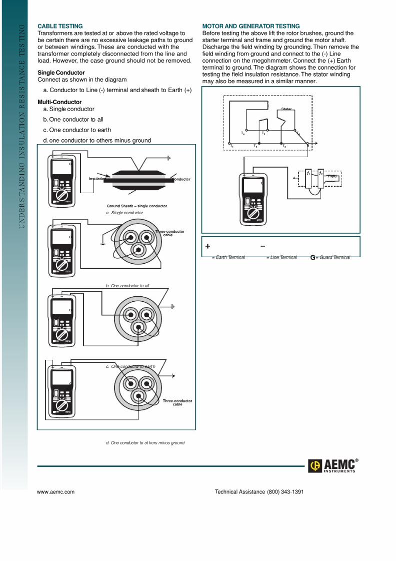
T E S T I N G CABLE TESTING
Transformers are tested at or above the rated voltage tobe certain there are no excessive leakage paths to groundor between windings.These are conducted with thetransformer completely disconnected from the line andload. However, the case ground should not be removed.
Single ConductorConnect as shown in the diagram
a. Conductor to Line (-) terminal and sheath to Earth (+)
Multi-Conductora. Single conductor
b. One conductor to all
c. One conductor to earth
d. one conductor to others minus ground
MOTOR AND GENERATOR TESTINGBefore testing the above lift the rotor brushes, ground thestarter terminal and frame and ground the motor shaft.Discharge the field winding by grounding. Then remove thefield winding from ground and connect to the (-) Lineconnection on the megohmmeter. Connect the (+) Earthterminal to ground.The diagram shows the connection fortesting the field insulation resistance.The stator windingmay also be measured in a similar manner.
Insulation Conductor
Ground Sheath – single conductor
Three-conductor cable
G
Three-conductor cable
G
G
G
b. One conductor to all
c. One conductor to eart h
d. One conductor to ot h er s mi nu s g round
a. S i n g le conductor
T4
T1
T3
T2
N
T6
T5
Stater
Fieldƒ1 ƒ
2
G
= Earth Terminal = Line Terminal = Guard TerminalG