Catálogo GeneralGeneral Catalogue
Válvula de Seguridad 3-5211 y 3-5261Safety Valve 3-5211 and 3-5261
DFL ITALIA S.r.l.Corso della Vittoria 2/A - 28100 NOVARA (NO)tel.:+39 (0) 321 18 14 685 / 18 13 061 - fax:+39 (0) 321 16 92 037
[email protected] www.dfl-italia.it
Represented in Italy by:
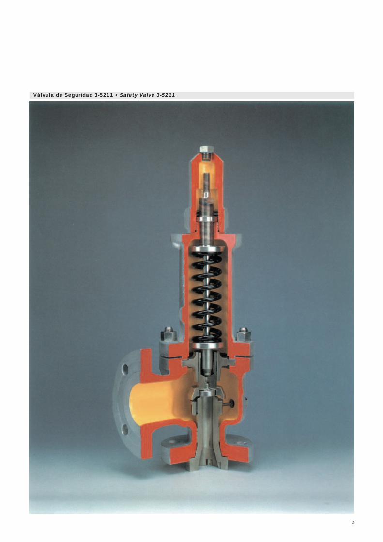
Válvula de Seguridad 3-5211 • Safety Valve 3-5211
2
3
Definiciones • Definitions
Las válvulas de seguridad y las válvulas de alivio de presión sonválvulas automáticas que tienen la función de mantener la presión deuna instalación por debajo de un límite preestablecido.Los principales términos relacionados con las mismas se explican acontinuación.
Válvula de SeguridadEs un regulador automático de presión cuya intervención es producidapor la presión estática existente en la entrada de la válvula y que secaracteriza por su descarga repentina con aperturas totales y rápidas(disparo). Se utiliza para gases y vapor.
Válvula de AlivioEs un regulador automático de presión cuya intervención es producidapor la presión estática existente en la entrada de la válvula. Su aperturase produce en forma proporcional al aumento de presión en la entrada.Se utiliza para líquidos.
Máxima Presión de Trabajo AdmisibleEs la máxima presión de trabajo permitida en los recipientes einstalaciones sometidos a presión. Depende de las normas aplicables,de las condiciones del proceso, del tipo de construcción y de lascaracterísticas mecánicas de los materiales utilizados. Coincidenormalmente con la presión de diseño y es la máxima presión detarado admisible de la válvula de seguridad.
Presión de TrabajoEs la presión a que se encuentra sometida la instalación en condicionesnormales de funcionamiento. Debe ser neceariamente inferior a lapresión de tarado, por lo menos en un 10%.
Presión de TaradoEs la presión de entrada a la cual está ajustada la válvula para queactúe (en las condiciones de servicio). A esta presión, la válvulacomienza la descarga evacuando una vena continua de fluido. Engases y vapor, un pequeño incremento sobre esta presión produceel disparo de la válvula (apertura total y rápida).
AcumulaciónEs el incremento de presión sobre la máxima presión de trabajoadmisible del recipiente protegido durante la descarga. Viene fijadapor la normativa relativa a la instalación.
SobrepresiónEs el incremento de presión sobre la presión de tarado necesaria paraalcanzar la apertura total de la válvula con la descarga del caudalmáximo. Su valor debe ser como máximo el de la acumulación si laválvula está tarada a la máxima presión de trabajo admisible. Se sueleadoptar el 10% para gases y vapor, y el 25% para líquidos.
Safety and pressure-relief valves are automatic valves for keeping thepressure of an installation below a pre-established limit.
The main terms used referring to them are explained below.
Safety ValveThis is an automatic pressure regulator actuated by thesuperimposed pressure at the valve inlet, being characterized by itssudden discharge with complete and fast opening (pop). Used forgases and vapours.
Relief ValveThis is an automatic pressure regulator actuated by thesuperimposed pressure at the valve inlet. It opens in proportion toincreases of pressure at the inlet. It is used for liquids.
Maximum Allowable Working PressureThis is the maximum working pressure permitted for receptaclesand installations subjected to pressure. This depends on applicablestandards, process conditions, type of construction and the mechanicalcharacteristics of the materials used. It normally coincides with thedesign pressure and is the maximum allowable set pressure of thesafety valve.
Operating PressureThis is the pressure to which the installation is subjected undernormal operating conditions. It must of necessity be at least 10%lower than the set pressure.
Set PressureThis is the inlet pressure at which the valve is set to operate (underservice conditions). The valve begins to discharge at this pressure,emitting a continuous stream of fluid. In the case of gases and vapours,a small increase of this pressure leads to valve pop (total, fast opening).
AccumulationThis is the pressure increase over the maximum allowable workingpressure of the protected vessel during discharge. It is set by theregulations on the installation.
OverpressureThis is the pressure increase over the set pressure necessary to leadto complete opening of the valve with maximum-flow discharge. Itsmaximum value must not exceed the accumulation value if the valveis set at the maximum allowable working pressure. 10% is usuallyadopted for gases and vapours, and 25% for liquids.
Caída de Presión. EscapeEs la disminución de presión respecto a la presión de tarado en elmomento del cierre de la válvula después de su actuación.
ElevaciónEs la carrera del órgano de obturación de la válvula desde suposición de cierre a la de máxima apertura.
Margen de ProporcionalidadEn una válvula de seguridad, es la carrera del órgano deobturación de la válvula desde que comienza su apertura hastaque se produce el disparo. No puede ser superior al 20% de laelevación total.
ContrapresiónEs la presión existente en el lado de descarga de la válvula. Es lasuma de las contrapresiones estática y dinámica.
Contrapresión EstáticaEs la presión existente en la salida de la válvula antes de la descarga.Puede ser constante o variable.
Contrapresión DinámicaEs la presión generada en la salida de la válvula por el efecto delflujo durante la descarga.
Presión de Tarado en FríoEs la presión de tarado en banco de la válvula, una vez aplicadassobre la presión de tarado en servicio las posibles correcciones porel efecto de la contrapresión y la temperatura.
BlowdownThis is the pressure reduction with respect to set pressure at the timeof closure of the valve following actuation thereof.
LiftThis is the stroke of the obstruction mechanism of the valve from itsclosure position to its maximum opening position.
Proportionality margin (Simmer)In a safety valve, this is the stroke of the obstruction mechanism ofthe valve from the point at which it commences opening up to the pointof pop. It cannot be higher than 20% of total lift.
Back PressureThis is the pressure at the discharge side of the valve. It is the sumof the superimposed and built-up back pressures.
Superimposed Back PressureThis is the pressure at the valve outlet prior to discharge. It can beconstant or variable.
Built-up Back PressureThis is the pressure generated at the valve outlet due to the effect offlow during discharge.
Cold Differential Test PressureThis is the bench-set pressure of the valve once the set servicepressure has had applied to it possible corrections due to the effectof back pressure and temperature.
4
Definiciones • Definitions
Las válvulas de seguridad modelos 3-5211 y 3-5261, por su diseño,robustez y fiabilidad, están especialmente recomendadas parainstalaciones de alta responsabilidad, como puede ser la industriapetroquímica o similares.
Su construcción es del tipo angular a 90° entre la brida de entraday salida, el cuerpo es de amplias medidas internas para evitarcontrapresiones en el momento de descarga, con asiento completoy carrera larga, tapa cerrada, mecanismo de obturación actuadomediante resorte helicoidal de acción directa.
Tanto el diseño como el cálculo y selección, así como su fabricacióny pruebas, están basadas en las siguientes normas:Cálculo API RP 520Diseño General ASME VIII y API-526Materiales ASTMPruebas API-527Coeficientedescarga homologado ISPESL (Italia)
Además de lo indicado en este catálogo, que corresponde a la versiónestandarizada, es posible la fabricación de estos modelos en otrosmateriales y tipos de bridas, así como dotarlas de numerososaccesorios.
Sobrepresión
Para obtener la máxima alzada de descarga del obutrador, necesitaráuna sobrepresión de:10% Para gases y vapores25% Para líquidos0,2 Bar Sobrepresión mínima
Cierre
El valor del cierre está comprendido entre el 7% y el 10% de la presiónde disparo. Este valor depende de la condición de proceso y del tipode fluido.
Regulación de la Presión
La tolerancia prevista sobre el valor de la presión de tarado es:10% Para presiones menores de 17 Bar 5% Para presiones mayores de 17 Bar
Coeficiente de Descarga
El coeficiente de descarga para gases y vapores ha sido homologadopor el ISPESL (Instituto Superiore per la Prevenzione e la Sicurezzadel Lavoro) Italia.K = 0,946 Para gases y vaporesK = 0,64 Para líquidos
Mínima Presión de Tarado
La presión mínima de tarado depende del modelo de válvula.0,5 Bar Modelo 3-5211 1 Bar Modelo 3-5261
Bridas de Conexión
Las válvulas pueden suministrarse con bridas de conexión segúnnorma ANSI B 16.5, DIN, o cualquier otra norma bajo demanda.
Encamisado
Todos los tipos de válvulas pueden ser calefactados con camisa enrating ANSI-150, PN-16, y conexiones de entrada y salida roscadas.
The design, robustness and reliability of the model 3-5211 and 3-5261safety valves make them specially suitable for highly critical installationssuch as those to be found in the petrochemical industry, refineries orthe like.
They are constructed with a 90° angle between the inlet and outlet,the valve body is of large internal dimensions in order to avoid backpressures when discharging, with full nozzle and long stroke, closedbonnet and obstruction mechanism actuated by direct-actions helicoidalspring.
Design, calculation and selection, manufacturing and testing are basedon the following standards:Calculation API RP 520General Design ASME VIII and API-526Materials ASTMTests API-527Homologateddischarge coeff. ISPESL (Italy)
In addition to the descriptions in this catalogue, wich relate to thestandardized version, these models can be manufactured in othermaterials and flange types and can be equipped with many accessories.
Overpressure
The follow overpressures are required to obtain the maximum dischargelift:10% For gases and vapours25% For liquids0,2 Bar Minimum overpressure
Closure
The closure value is between 7% and 10% of the set pressure. Thisvalue depends on process status and the type of fluid.
Pressure Regulation
The tolerance margins of the set pressure are:10% For pressures below 17 Bar 5% For pressures above 17 Bar
Discharge Coefficient
The discharge coefficient for gases and vapours has been homologated bythe ISPESL (Instituto Superiore per la Prevenzione e la Sicurezza delLavoro-Higher Institute for Health and Safety in the Workplace) of Italy.K = 0,946 For gases and vapoursK = 0,64 For liquids
Minimum Set Pressure
The minimum set pressure depends on the valve model.0,5 Bar Model 3-5211 1 Bar Model 3-5261
Connection Flanges
The valves can be supplied with connections flanges as per standardANSI B 16.5, DIN, or any other standard to order.
Heating Jacket
All valve types can be heated with heating jacket at rating ANSI-150,PN-16, and inlet and outlet connections threaded.
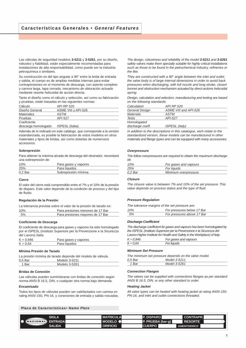
MATRICULAMODELOORIFICIO
P. DISPAROP. PRUEBA (bar-g)CUERPO
CONTRAPR.RESORTE
SIGLAENTRADASALIDA ASIENTO/DISCO
Placa de Características• Name Plate
5
Características Generales • General Features
Características Generales • General Features
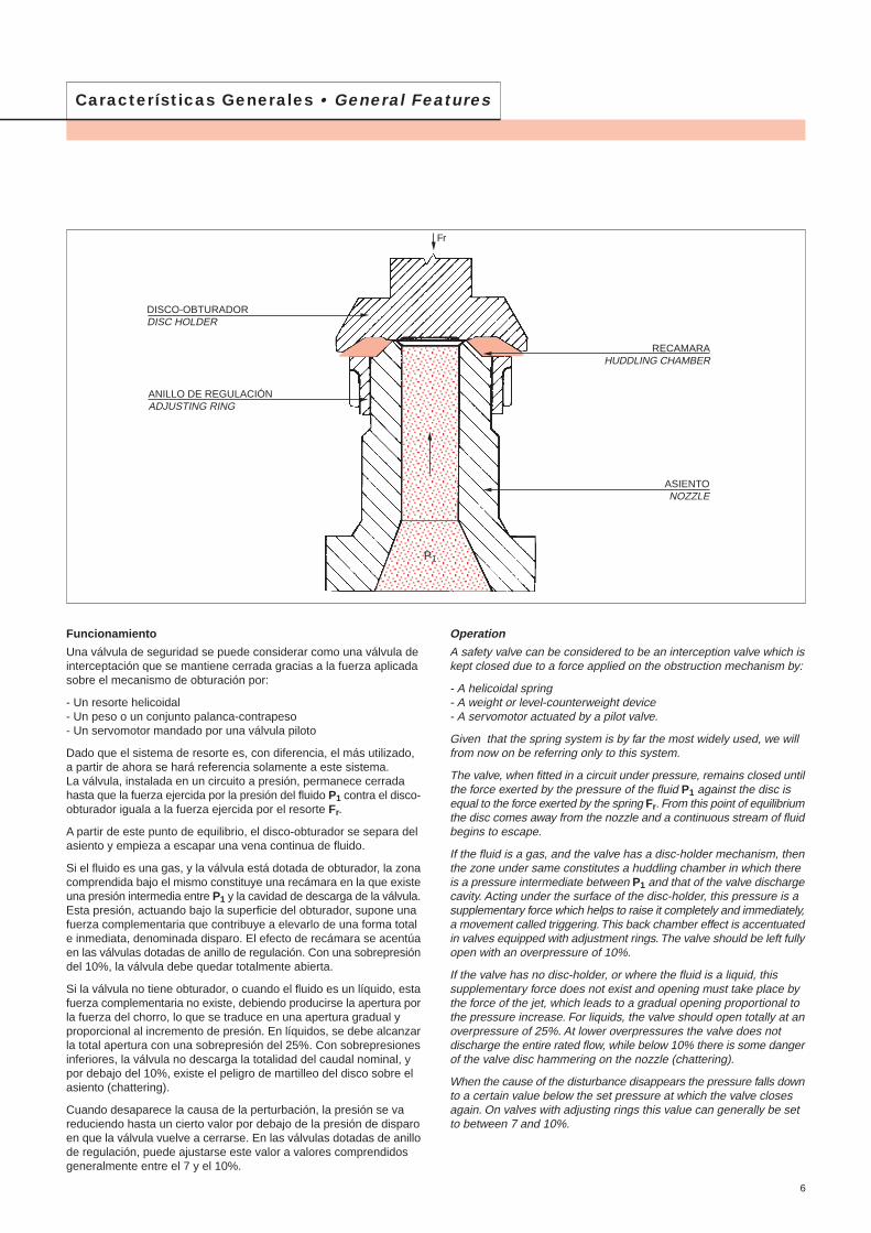
Funcionamiento
Una válvula de seguridad se puede considerar como una válvula deinterceptación que se mantiene cerrada gracias a la fuerza aplicadasobre el mecanismo de obturación por:
- Un resorte helicoidal - Un peso o un conjunto palanca-contrapeso- Un servomotor mandado por una válvula piloto
Dado que el sistema de resorte es, con diferencia, el más utilizado,a partir de ahora se hará referencia solamente a este sistema.La válvula, instalada en un circuito a presión, permanece cerradahasta que la fuerza ejercida por la presión del fluido P1 contra el disco-obturador iguala a la fuerza ejercida por el resorte Fr.
A partir de este punto de equilibrio, el disco-obturador se separa delasiento y empieza a escapar una vena continua de fluido.
Si el fluido es una gas, y la válvula está dotada de obturador, la zonacomprendida bajo el mismo constituye una recámara en la que existeuna presión intermedia entre P1 y la cavidad de descarga de la válvula.Esta presión, actuando bajo la superficie del obturador, supone unafuerza complementaria que contribuye a elevarlo de una forma totale inmediata, denominada disparo. El efecto de recámara se acentúaen las válvulas dotadas de anillo de regulación. Con una sobrepresióndel 10%, la válvula debe quedar totalmente abierta.
Si la válvula no tiene obturador, o cuando el fluido es un líquido, estafuerza complementaria no existe, debiendo producirse la apertura porla fuerza del chorro, lo que se traduce en una apertura gradual yproporcional al incremento de presión. En líquidos, se debe alcanzarla total apertura con una sobrepresión del 25%. Con sobrepresionesinferiores, la válvula no descarga la totalidad del caudal nominal, ypor debajo del 10%, existe el peligro de martilleo del disco sobre elasiento (chattering).
Cuando desaparece la causa de la perturbación, la presión se vareduciendo hasta un cierto valor por debajo de la presión de disparoen que la válvula vuelve a cerrarse. En las válvulas dotadas de anillode regulación, puede ajustarse este valor a valores comprendidosgeneralmente entre el 7 y el 10%.
Operation
A safety valve can be considered to be an interception valve which iskept closed due to a force applied on the obstruction mechanism by:
- A helicoidal spring - A weight or level-counterweight device- A servomotor actuated by a pilot valve.
Given that the spring system is by far the most widely used, we willfrom now on be referring only to this system.
The valve, when fitted in a circuit under pressure, remains closed untilthe force exerted by the pressure of the fluid P1 against the disc isequal to the force exerted by the spring Fr. From this point of equilibriumthe disc comes away from the nozzle and a continuous stream of fluidbegins to escape.
If the fluid is a gas, and the valve has a disc-holder mechanism, thenthe zone under same constitutes a huddling chamber in which thereis a pressure intermediate between P1 and that of the valve dischargecavity. Acting under the surface of the disc-holder, this pressure is asupplementary force which helps to raise it completely and immediately,a movement called triggering. This back chamber effect is accentuatedin valves equipped with adjustment rings. The valve should be left fullyopen with an overpressure of 10%.
If the valve has no disc-holder, or where the fluid is a liquid, thissupplementary force does not exist and opening must take place bythe force of the jet, which leads to a gradual opening proportional tothe pressure increase. For liquids, the valve should open totally at anoverpressure of 25%. At lower overpressures the valve does notdischarge the entire rated flow, while below 10% there is some dangerof the valve disc hammering on the nozzle (chattering).
When the cause of the disturbance disappears the pressure falls downto a certain value below the set pressure at which the valve closesagain. On valves with adjusting rings this value can generally be setto between 7 and 10%.
6
Fr
RECAMARAHUDDLING CHAMBER
ASIENTONOZZLE
DISCO-OBTURADORDISC HOLDER
ANILLO DE REGULACIÓNADJUSTING RING
P1
Características Generales • General Features
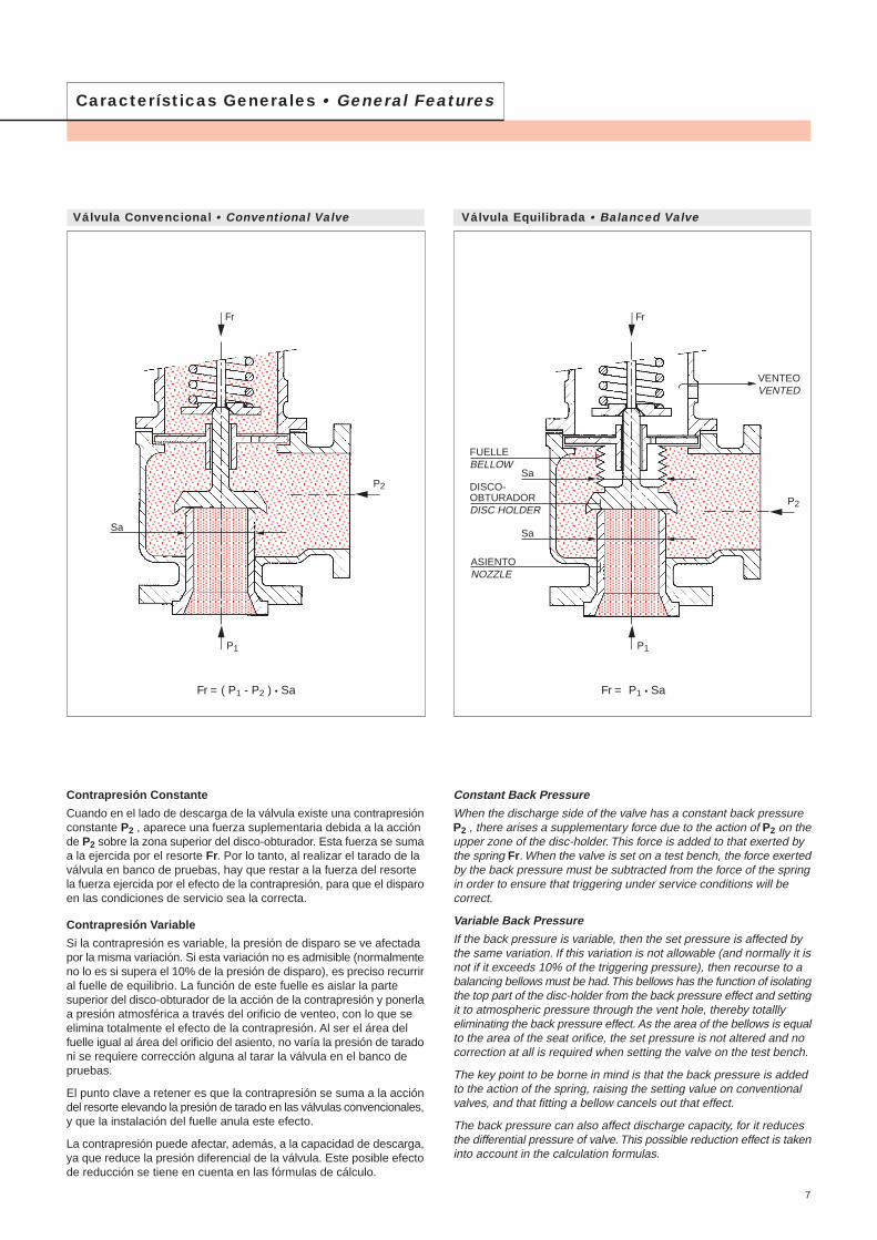
Contrapresión Constante
Cuando en el lado de descarga de la válvula existe una contrapresiónconstante P2 , aparece una fuerza suplementaria debida a la acciónde P2 sobre la zona superior del disco-obturador. Esta fuerza se sumaa la ejercida por el resorte Fr. Por lo tanto, al realizar el tarado de laválvula en banco de pruebas, hay que restar a la fuerza del resortela fuerza ejercida por el efecto de la contrapresión, para que el disparoen las condiciones de servicio sea la correcta.
Contrapresión Variable
Si la contrapresión es variable, la presión de disparo se ve afectadapor la misma variación. Si esta variación no es admisible (normalmenteno lo es si supera el 10% de la presión de disparo), es preciso recurriral fuelle de equilibrio. La función de este fuelle es aislar la partesuperior del disco-obturador de la acción de la contrapresión y ponerlaa presión atmosférica a través del orificio de venteo, con lo que seelimina totalmente el efecto de la contrapresión. Al ser el área delfuelle igual al área del orificio del asiento, no varía la presión de taradoni se requiere corrección alguna al tarar la válvula en el banco depruebas.
El punto clave a retener es que la contrapresión se suma a la accióndel resorte elevando la presión de tarado en las válvulas convencionales,y que la instalación del fuelle anula este efecto.
La contrapresión puede afectar, además, a la capacidad de descarga,ya que reduce la presión diferencial de la válvula. Este posible efectode reducción se tiene en cuenta en las fórmulas de cálculo.
Constant Back Pressure
When the discharge side of the valve has a constant back pressureP2 , there arises a supplementary force due to the action of P2 on theupper zone of the disc-holder. This force is added to that exerted bythe spring Fr. When the valve is set on a test bench, the force exertedby the back pressure must be subtracted from the force of the springin order to ensure that triggering under service conditions will becorrect.
Variable Back Pressure
If the back pressure is variable, then the set pressure is affected bythe same variation. If this variation is not allowable (and normally it isnot if it exceeds 10% of the triggering pressure), then recourse to abalancing bellows must be had. This bellows has the function of isolatingthe top part of the disc-holder from the back pressure effect and settingit to atmospheric pressure through the vent hole, thereby totalllyeliminating the back pressure effect. As the area of the bellows is equalto the area of the seat orifice, the set pressure is not altered and nocorrection at all is required when setting the valve on the test bench.
The key point to be borne in mind is that the back pressure is addedto the action of the spring, raising the setting value on conventionalvalves, and that fitting a bellow cancels out that effect.
The back pressure can also affect discharge capacity, for it reducesthe differential pressure of valve. This possible reduction effect is takeninto account in the calculation formulas.
Válvula Convencional • Conventional Valve Válvula Equilibrada • Balanced Valve
Fr = ( P1 - P2 ) • Sa Fr = P1 • Sa
7
Fr
P1
Sa
P2
FUELLEBELLOW
ASIENTONOZZLE
DISCO-OBTURADORDISC HOLDER
VENTEOVENTED
Fr
P1
Sa
Sa
P2
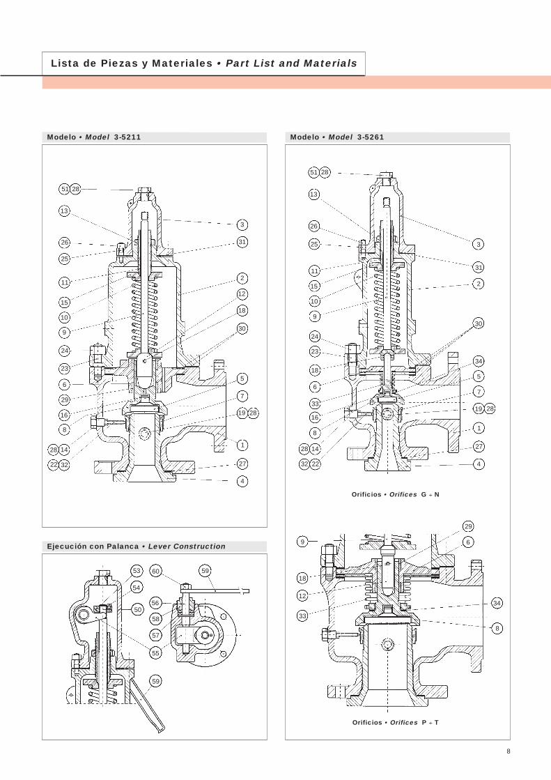
Lista de Piezas y Materiales • Part List and Materials
Modelo • Model 3-5211 Modelo • Model 3-5261
Ejecución con Palanca • Lever Construction
58
53
54
50
60
56
59
55
57
59
Orificios • Orifices G ÷ N
Orificios • Orifices P ÷ T
15
51 28
13
26
25
11
8
9
24
23
6
33
28
16
2232
14
5
3
31
2
30
34
7
19 28
1
27
18
10
4
29
9
18
12
33
6
8
34
15
51 28
13
26
25
10
11
8
9
24
23
6
29
28
16
22 32
14
5
3
31
2
12
18
7
30
19 28
1
27
4
8
A 351 CF 8M
AISI 316
A 351 CF 8M
A 351 CF 8M
AISI 316
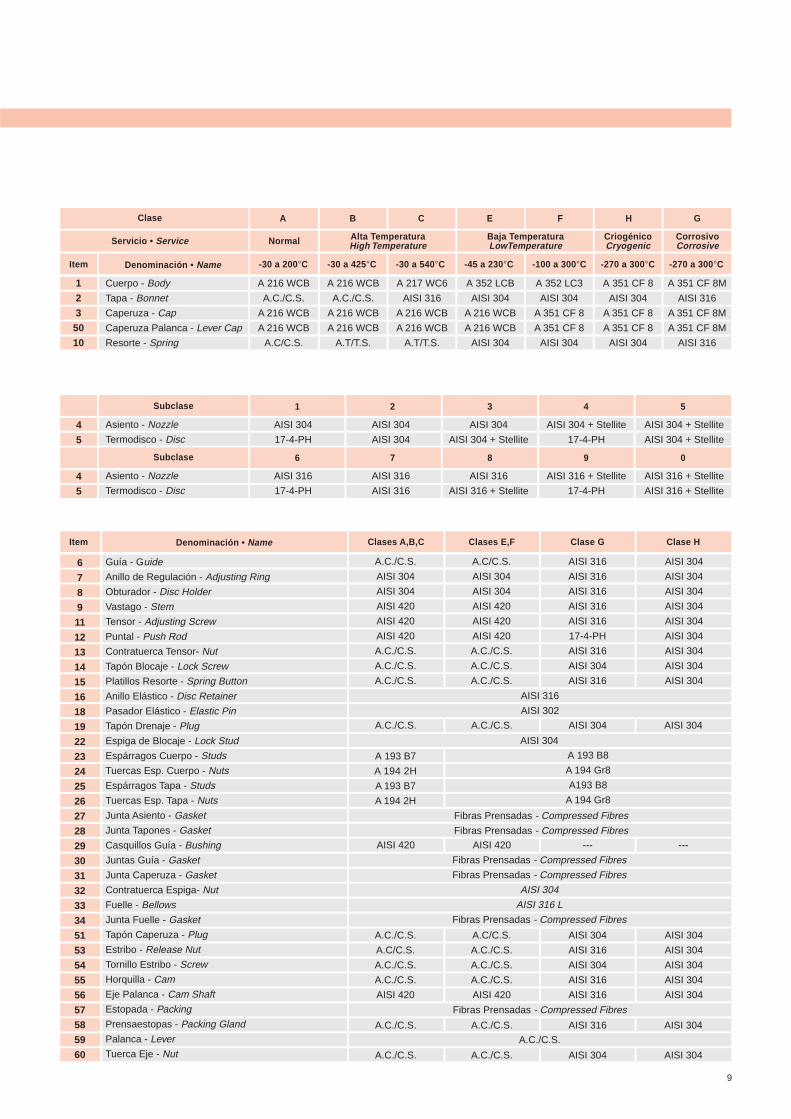
Servicio • Service
Clase
Item Denominación • Name
Normal
-30 a 200°C
B
-30 a 425°C
C
-30 a 540°C
E
-45 a 230°C
F
-100 a 300°C
H
-270 a 300°C
G
-270 a 300°C
Alta TemperaturaHigh Temperature
Baja TemperaturaLowTemperature
CriogénicoCryogenic
CorrosivoCorrosive
1
2
3
50
10
A 351 CF 8
AISI 304
A 351 CF 8
A 351 CF 8
AISI 304
A 352 LC3
AISI 304
A 351 CF 8
A 351 CF 8
AISI 304
A 352 LCB
AISI 304
A 216 WCB
A 216 WCB
AISI 304
A 216 WCB
A.C./C.S.
A 216 WCB
A 216 WCB
A.C/C.S.
Cuerpo - Body
Tapa - Bonnet
Caperuza - Cap
Caperuza Palanca - Lever Cap
Resorte - Spring
A 216 WCB
A.C./C.S.
A 216 WCB
A 216 WCB
A.T/T.S.
A 217 WC6
AISI 316
A 216 WCB
A 216 WCB
A.T/T.S.
A
AISI 304 + Stellite
AISI 304 + Stellite
1Subclase 2 3 4 5
AISI 304 + Stellite
17-4-PH
AISI 304
AISI 304 + Stellite
AISI 304
AISI 304
AISI 304
17-4-PH
Asiento - Nozzle
Termodisco - Disc4
5
AISI 316 + Stellite
AISI 316 + Stellite
6Subclase 7 8 9 0
AISI 316 + Stellite
17-4-PH
AISI 316
AISI 316 + Stellite
AISI 316
AISI 316
AISI 316
17-4-PH
Asiento - Nozzle
Termodisco - Disc4
5
9
AISI 304
AISI 304
AISI 304
AISI 304
AISI 304
AISI 304
AISI 304
AISI 304
AISI 304
Item Denominación • Name Clases A,B,C
6
7
8
9
11
12
13
14
15
16
18
19
22
23
24
25
26
27
28
29
30
31
32
33
34
51
53
54
55
56
57
58
59
60
Guía - Guide
Anillo de Regulación - Adjusting Ring
Obturador - Disc Holder
Vastago - Stem
Tensor - Adjusting Screw
Puntal - Push Rod
Contratuerca Tensor- Nut
Tapón Blocaje - Lock Screw
Platillos Resorte - Spring Button
Anillo Elástico - Disc Retainer
Pasador Elástico - Elastic Pin
Tapón Drenaje - Plug
Espiga de Blocaje - Lock Stud
Espárragos Cuerpo - Studs
Tuercas Esp. Cuerpo - Nuts
Espárragos Tapa - Studs
Tuercas Esp. Tapa - Nuts
Junta Asiento - Gasket
Junta Tapones - Gasket
Casquillos Guía - Bushing
Juntas Guía - Gasket
Junta Caperuza - Gasket
Contratuerca Espiga- Nut
Fuelle - Bellows
Junta Fuelle - Gasket
Tapón Caperuza - Plug
Estribo - Release Nut
Tornillo Estribo - Screw
Horquilla - Cam
Eje Palanca - Cam Shaft
Estopada - Packing
Prensaestopas - Packing Gland
Palanca - Lever
Tuerca Eje - Nut
Clases E,F Clase G Clase H
AISI 316
AISI 316
AISI 316
AISI 316
AISI 316
17-4-PH
AISI 316
AISI 304
AISI 316
A.C/C.S.
AISI 304
AISI 304
AISI 420
AISI 420
AISI 420
A.C./C.S.
A.C./C.S.
A.C./C.S.
A.C./C.S.
AISI 304
AISI 304
AISI 420
AISI 420
AISI 420
A.C./C.S.
A.C./C.S.
A.C./C.S.
AISI 316
AISI 302
AISI 304
Fibras Prensadas - Compressed Fibres
Fibras Prensadas - Compressed Fibres
Fibras Prensadas - Compressed Fibres
Fibras Prensadas - Compressed Fibres
AISI 304
AISI 316 L
Fibras Prensadas - Compressed Fibres
Fibras Prensadas - Compressed Fibres
A.C./C.S.
A 193 B8
A 194 Gr8
A193 B8
A 194 Gr8
A.C./C.S. A.C./C.S. AISI 304 AISI 304
AISI 420 AISI 420 --- ---
AISI 304
AISI 304
AISI 304
AISI 304
AISI 304
AISI 304
AISI 316
AISI 304
AISI 316
AISI 316
A.C/C.S.
A.C./C.S.
A.C./C.S.
A.C./C.S.
AISI 420
A.C./C.S.
A.C/C.S.
A.C./C.S.
A.C./C.S.
AISI 420
A.C./C.S. A.C./C.S. AISI 316 AISI 304
A.C./C.S. A.C./C.S. AISI 304 AISI 304
A 193 B7
A 194 2H
A 193 B7
A 194 2H
18
24
28
29
44
50
72
120
200
230
375
20
26
31
48
55
76
140
212
248
28
33
54
87
170
258
31
37
62
95
130
195
42
66
20
26
30
31
47
53
77
128
208
238
385
22
28
33
51
58
81
148
220
256
30
35
57
92
180
266
33
39
65
100
135
205
44
69
14
18
18
18
19
19
19
20
22
22
28
14
18
18
19
19
19
21
22
22
18
18
19
19
21
25
18
18
19
19
19
25
18
19
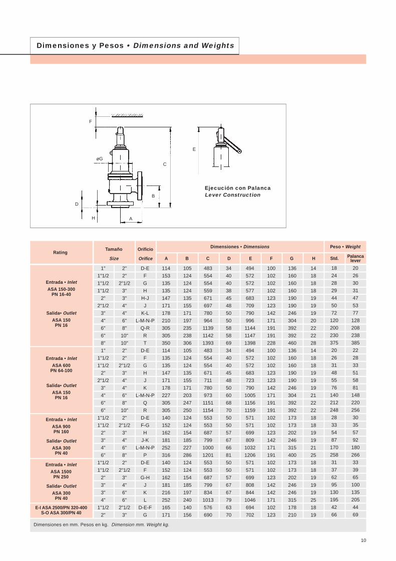
RatingTamaño
Size
Orificio
Orifice
Dimensiones • Dimensions
A B C D E F G H Std. Palancalever
Peso • Weight
Entrada • InletASA 150-300
PN 16-40
Salida• OutletASA 150
PN 16
Entrada • InletASA 600
PN 64-100
Salida• OutletASA 150
PN 16
Entrada • InletASA 900PN 160
Salida• OutletASA 300
PN 40
Entrada • InletASA 1500
PN 250
Salida• OutletASA 300
PN 40
E-I ASA 2500/PN 320-400S-O ASA 300/PN 40
Dimensiones en mm. Pesos en kg. Dimension mm. Weight kg.
136
160
160
160
190
190
246
304
392
392
460
136
160
160
190
190
246
304
392
392
173
173
202
246
315
400
173
173
202
246
246
315
178
210
100
102
102
102
123
123
142
171
191
191
228
100
102
102
123
123
142
171
191
191
102
102
123
142
171
191
102
102
123
142
142
171
102
123
494
572
572
577
683
709
790
996
1144
1147
1398
494
572
572
683
723
790
1005
1156
1159
571
571
699
809
1032
1206
571
571
699
808
844
1046
694
702
34
40
40
38
45
48
50
50
58
58
69
34
40
40
45
48
50
60
68
70
50
50
57
67
66
81
50
50
57
67
67
79
63
70
483
554
554
559
671
697
780
964
1139
1142
1393
483
554
554
671
711
780
973
1151
1154
553
553
687
799
1000
1201
553
553
687
799
834
1013
576
690
105
124
124
124
135
155
171
197
235
238
306
105
124
124
135
155
171
203
247
250
124
124
154
185
227
286
124
124
154
185
197
240
140
156
114
153
135
135
147
171
178
210
305
305
350
114
135
135
147
171
178
227
305
305
140
152
162
181
252
316
140
152
162
181
216
252
165
171
D-E
F
G
H
H-J
J
K-L
L-M-N-P
Q-R
R
T
D-E
F
G
H
J
K
L-M-N-P
Q
R
D-E
F-G
H
J-K
L-M-N-P
P
D-E
F
G-H
J
K
L
D-E-F
G
2"
2"
2"1/2
3"
3"
4"
4"
6"
8"
10"
10"
2"
2"
2"1/2
3"
4"
4"
6"
8"
10"
2"
2"1/2
3"
4"
6"
8"
2"
2"1/2
3"
4"
6"
6"
2"1/2
3"
1"
1"1/2
1"1/2
1"1/2
2"
2"1/2
3"
4"
6"
6"
8"
1"
1"1/2
1"1/2
2"
2"1/2
3"
4"
6"
6"
1"1/2
1"1/2
2"
3"
4"
6"
1"1/2
1"1/2
2"
3"
3"
4"
1"1/2
2"
Dimensiones y Pesos • Dimensions and Weights
H
Ejecución con PalancaLever Construction
A
B
C
D
E
F
øG
10
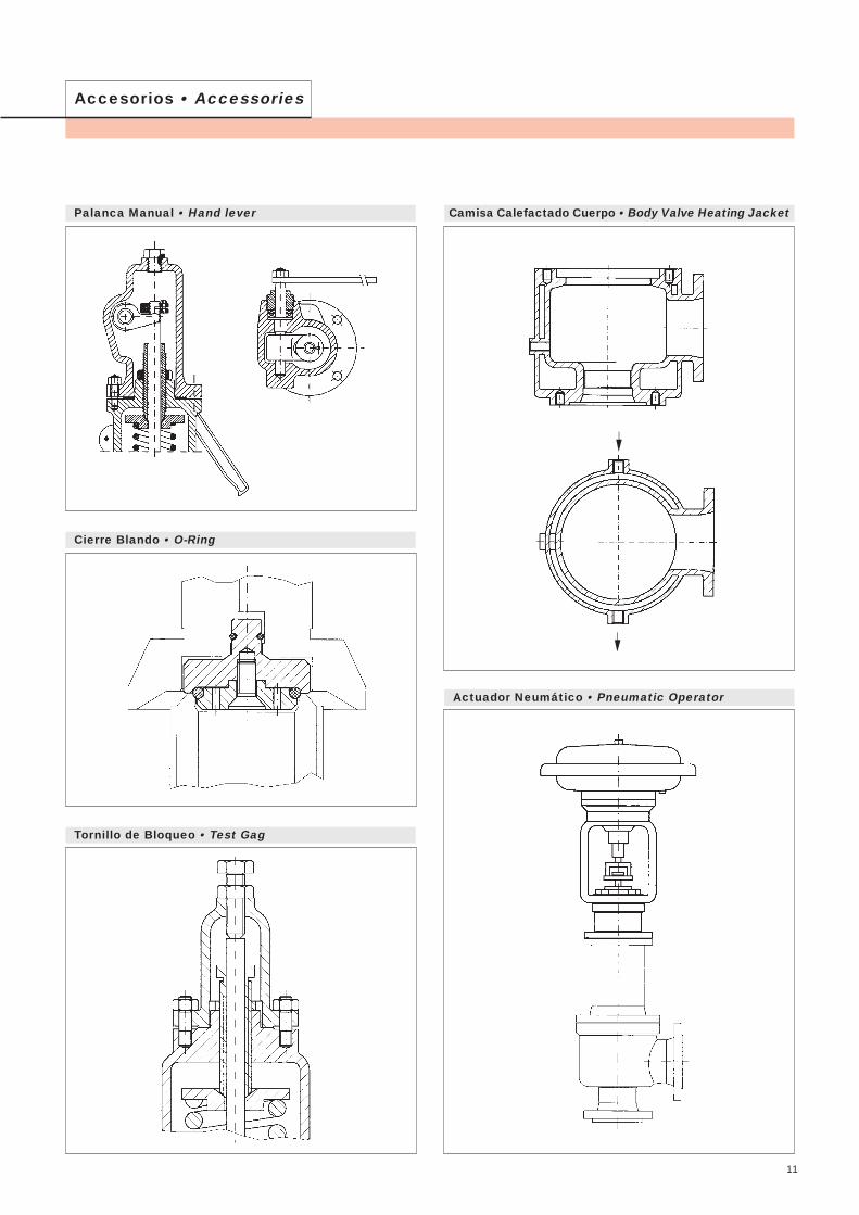
Accesorios • Accessories
Palanca Manual • Hand lever Camisa Calefactado Cuerpo • Body Valve Heating Jacket
Actuador Neumático • Pneumatic Operator
Cierre Blando • O-Ring
Tornillo de Bloqueo • Test Gag
11

12
Información TécnicaTechnical Information
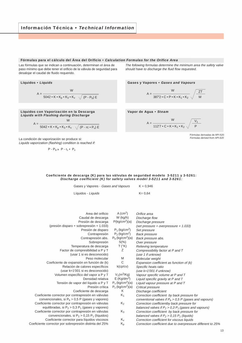
Información Técnica • Technical Information
Fórmulas para el cálculo del Área del Orificio • Calculation Formulas for the Orifice AreaLas fórmulas que se indican a continuación, determinan el área depaso mínimo que debe tener el orificio de la válvula de seguridad paradesalojar el caudal de fluido requerido.
The following formulas determine the minimum area the safety valveshould have to discharge the fluid flow requested.
Líquidos • Liquids
Líquidos con Vaporización en la DescargaLiquids with Flashing during Discharge
Gases y Vapores • Gases and Vapours
Vapor de Agua • Steam
La condición de vaporización se produce si:Liquids vaporization (flashing) condition is reached if:
P - Pb ≥ P - rc • Pv
Fórmulas derivadas de API-520Formulas derived from API-520
Coeficiente de descarga (K) para las válvulas de seguridad modelo 3-5211 y 3-5261:Discharge coefficient (K) for safety valves model 3-5211 and 3-5261:
Gases y Vapores - Gases and Vapours K = 0,946
Líquidos - Liquids K= 0,64
5042 • K • Kp • K3 • Kv
A =W
(P - Pb) E
5042 • K • Kp • K3 • Kv
A =W
(P - rc • Pv) E
387'2 • C • P • K • K1 • K2
A =W ZT
M
112'7 • C • K • K1 • K2
A =W V1
P
13
Area del orificioCaudal de descargaPresión de descarga
(presión disparo + sobrepresión + 1.033)Presión de disparo
ContrapresiónContrapresión abs.
SobrepresiónTemperatura de descarga
Factor de compresibilidad a P y T(usar 1 si es desconocido)
Peso molecularCoeficiente de expansión en función de (k)
Relación de calores específicos(usar k=1'001 si es desconocido)
Volumen específico del vapor a P y TDensidad relativa
Tensión de vapor del líquido a P y TPresión crítica
Coeficiente de descargaCoeficiente corrector por contrapresión en válvulas
convencionales, si Pb > 0,5 P (gases y vapores)Coeficiente corrector por contrapresión en válvulas
equilibradas, si P2 > 0,3 P1 (gases y vapores)Coeficiente corrector por contrapresión en válvulas
convencionales, si P2 > 0,15 P1 (líquidos)Coeficiente corrector para líquidos viscosos
Coeficiente corrector por sobrepresión distinta del 25%
Orifice areaDischarge flowDischarge pressure(set pressure + overpressure + 1.033)Set pressureBack pressureBack pressure abs.Over pressureRelieving temperatureCompressibility factor at P and T(use 1 if unknow)Molecular weightExpansion coefficient as function of (k)Specific heats ratio(use k=1'001 if unknow)Vapour specific volume at P and TLiquid specific gravity at P and TLiquid vapour pressure at P and TCritical pressureDischarge coefficientCorrection coefficient by back pressure forconventional valves if Pb > 0,5 P (gases and vapours)Correction coefficientby back pressure forbalanced valves if P2 > 0,3 P1 (gases and vapours) Correction coefficient by back pressure forbalanced valves if P2 > 0,15 P1 (liquids)Correction coefficient for viscous liquidsCorrection coefficient due to overpressure different to 25%
A (cm2)W (kg/h)
P(kg/cm2)(a)
P1 (kg/cm2)P2 (kg/cm2)
Pb (kg/cm2)(a)S(%)T (°K)
Z
MC
k(cp/cv)
V1(m3/Kg)E (Kg/dm3)
Pv (kg/cm2)(a)Pc (kg/cm2)(a)
KK1
K2
K3
KvKp
Peso EspecíficoSpecific Gravity
Fluidos
26'04
60'05
36'47
28'96
46'07
32'00
17'03
64'06
39'94
78'11
58'12
58'12
70'91
44'01
165
30'07
28'05
120'92
86'48
19
4
100'20
86'17
2'02
16'04
28'02
114'22
44'02
32
72'15
44'09
76'13
Acetileno
Ácido Acético
Ácido Clorhídrico
Ácido Nítrico
Ácido Sulfúrico
Aire
Alcohol Etílico
Alcohol Metílico
Amoniaco
Anhídrido Sulfuroso
Argón
Benceno
Butano - n
Butano - iso
Cloro
Dióxido de Carbono
Dowtherm - A
Etano
Etileno
Freon - 12
Freon - 22
Fuel Oil
Gas Natural
Gasolina
Helio
Heptano - n
Hexano - n
Hidrógeno
Keroseno
Metano
Nitrógeno
Octano - n
Óxido Nitroso
Oxígeno
Pentano - n
Propano
Sulfuro de Carbono
M k = cp /cv(1)
Punto CríticoCritical Point
Presión•PressureKg/cm2
Gas•GasKg/Nm3
Líquido•LiquidKg/dm3
Temp.•Temp.°C
P.Esp.•Sp.Grav.Kg/dm3
Fluids
Acetylene
Acetic Acid
Hydrochloric Acid
Nitric Acid
Sulfuric Acid
Air
Ethyl Alcohol
Methyl Alcohol
Ammonia
Sulfhur Dioxide
Argon
Benzene
Butane - n
Butane - iso
Chlorine
Carbon Dioxide
Dowtherm - A
Ethane
Ethylene
Freon - 12
Freon - 22
Fuel Oil
Natural Gas
Gasoline
Helium
Heptane - n
Hexane - n
Hydrogen
Kerosene
Metane
Nitrogen
Octane - n
Nitrous Oxide
Oxygen
Pentane - n
Propane
Carbon Disulphide
1'26
1'15
1'41
1'41
1'13
1'20
1'31
1'29
1'67
1'12
1'09
1'10
1'35
1'30
1'05
1'19
1'24
1'14
1'18
1'27
1'66
1'05
1'06
1'41
1'31
1'40
1'05
1'30
1'4
1'07
1'13
1'21
1'171
2'681
1'639
1'293
2'057
1'429
0'771
2'922
1'784
3'487
2'703
2'668
3'22
1'977
7'365
1'356
1'261
5'397
3'860
0'853
0'179
4'473
3'847
0'090
0'717
1'251
5'099
1'978
1'429
3'221
2'019
3'398
0'613
1'049
1'502
1'834
0'875
0'789
0'792
0'680
1'434
1'404
0'879
0'600
0'595
1'558
1'101
0'997
0'546
0'568
1'486
1'419
0'899
0'75
0'125
0'659
0'071
0'815
0'415
0'810
0'707
1'226
1'131
0'631
0'585
1'263
64'7
59
86
38'4
65'1
102'3
115'2
80'4
49'6
49'6
37'2
37'7
78'5
75
50'6
52'4
2'33
27'8
30'8
13'2
47'2
34'6
25'5
74
51'4
34'1
43'3
77'5
35'7
321'6
51'4
-140'7
243
240
132'4
157'3
-122'4
288'6
153'2
133'7
144
31
35
9'5
-267'9
266'8
234'8
-239'9
-82'5
-147'1
296'2
36'5
-118'8
197
96'8
277
0'231
0'351
0'61
0'310
0'280
0'358
0'235
0'524
0'531
0'305
0'573
0'46
0'21
0'216
0'069
0'234
0'234
0'031
0'162
0'311
0'233
0'46
0'43
0'232
0'226
0'441
Información Técnica • Technical Information
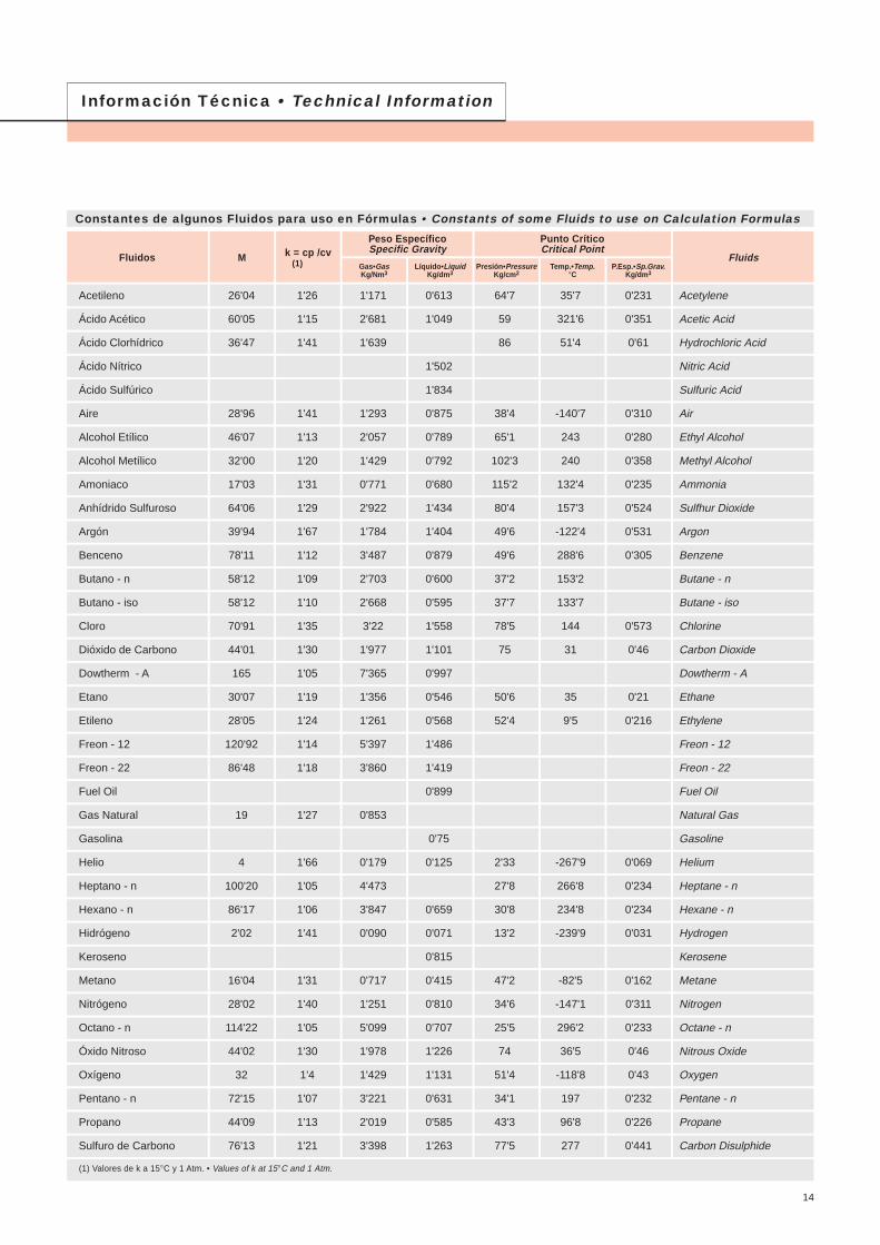
Constantes de algunos Fluidos para uso en Fórmulas • Constants of some Fluids to use on Calculation Formulas
(1) Valores de k a 15°C y 1 Atm. • Values of k at 15°C and 1 Atm.
14
0'400'450'500'550'600'650'700'750'800'820'840'860'880'900'920'940'960'980'991'001
0'4170'4390'4590'4780'4960'5120'5280'5430'5570'5620'5670'5730'5780'5830'5880'5930'5970'6020'6040'607
1'011'021'041'061'081'101'121'141'161'181'201'221'241'261'281'301'321'341'361'38
0'6090'6110'6150'6200'6240'6280'6330'6370'6410'6450'6490'6520'6560'6600'6640'6670'6710'6740'6780'681
1'401'421'441'461'481'501'521'541'561'581'601'621'641'661'681'701'721'741'781'80
0'6850'6880'6910'6950'6980'7010'7040'7070'7100'7130'7160'7190'7220'7250'7280'7310'7340'7360'7420'745
1'821'841'861'881'901'921'941'961'982'002'102'202'302'402'502'602'7'2'802'903'00
0'7470'7500'7520'7550'7580'7600'7630'7650'7670'7700'7810'7930'8030'8130'8230'8320'8410'8500'8580'866
k C k C k C k C
P1 bar abs
200 (473'15)250 (523'15)300 (573'15)350 (623'15)400 (673'15)450 (723'15)500 (773'15)550 (823'15)600 (873'15)650 (923'15)700 (973'15)
---
1'271'281'281'281'281'271'271'26
---
1'261'281'281'281'281'271'271'26
---
1'251'281'291'291'281'281'271'27
---
1'251'281'291'291'291'281'281'27
---
1'251'281'291'301'291'291'281'27
----
1'281'291'301'291'291'281'27
----
1'281'301'311'301'301'291'28
----
1'301'311'321'311'301'291'29
----
1'311'321'331'311'311'301'29
----
1'321'341'341'321'321'301'29
----
1'331'361'351'331'321'301'30
----
1'351'371'361'341'321'311'30
303'31576'461'25
310'96584'111'25
324'64597'791'24
336'63609'781'24
347'32620'471'24
356'96630'111'25
365'71638'861'27
373'68646'831'30
---
---
---
---
Vap
or
Sat
ura
do
Sat
urat
edS
team
T1 °C (°K)90 100 120 140 160 180 200 220 240 260 280 300
T1 °C°Kk = cp/cv
P1 bar abs
200 (473'15)250 (523'15)300 (573'15)350 (623'15)400 (673'15)450 (723'15)500 (773'15)550 (823'15)600 (873'15)650 (923'15)700 (973'15)
1'311'311'301'301'291'281'281'271'271'261'26
1'311'311'301'301'291'281'281'271'271'261'26
1'311'301'301'291'291'281'281'271'271'261'26
1'301'301'291'291'291'281'281'271'271'261'26
1'291'291'291'291'291'281'281'271'271'261'26
-1'281'291'291'291'281'281'271'271'261'26
--
1'291'291'281'281'281'271'271'261'26
--
1'281'281'281'281'281'271'271'261'26
--
1'271'281'281'281'281'271'271'261'26
--
1'271'281'281'281'281'271'271'261'26
--
1'261'271'281'281'281'281'271'271'26
--
1'261'271'281'281'281'281'271'271'26
99'63372'781'32
133'54406'691'31
151'85425'001'31
179'88453'031'30
198'28471'431'29
212'37485'521'29
233'84506'991'28
250'33523'481'27
263'92537'071'27
275'56548'711'26
285'80558'951'26
294'98568'131'25
Vap
or
Sat
ura
do
Sat
urat
edS
team
T1 °C (°K)1 3 5 10 15 20 30 40 50 60 70 80
T1 °C°Kk = cp/cv
Información Técnica • Technical Information
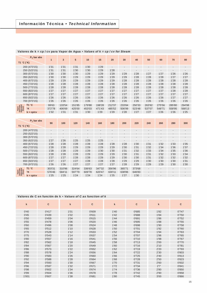
Valores de k = cp / cv para Vapor de Agua • Values of k = cp / cv for Steam
Valores de C en función de k • Values of C as function of k
15
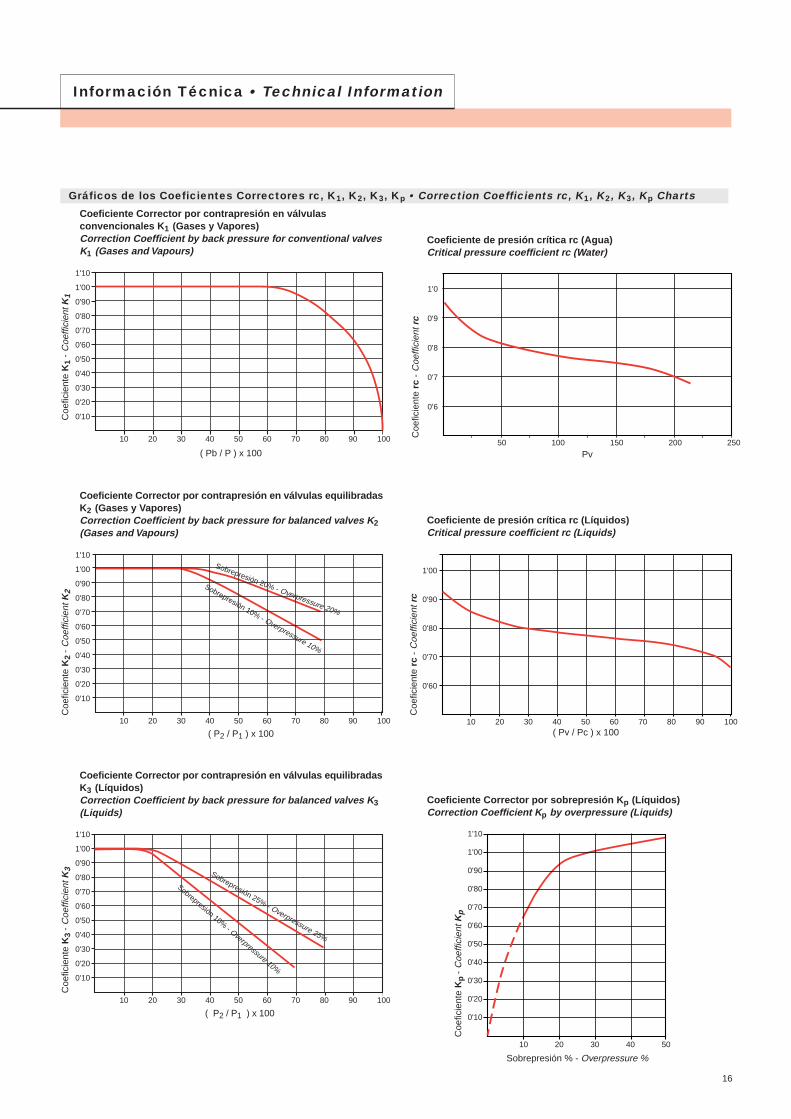
Gráficos de los Coeficientes Correctores rc, K1, K2, K3, Kp • Correction Coefficients rc, K1, K2, K3, Kp Charts
Información Técnica • Technical Information
Coeficiente Corrector por sobrepresión Kp (Líquidos)Correction Coefficient Kp by overpressure (Liquids)
Coe
ficie
nte
Kp
- C
oeffi
cien
t Kp
Sobrepresión % - Overpressure %
Coeficiente Corrector por contrapresión en válvulas equilibradasK2 (Gases y Vapores)Correction Coefficient by back pressure for balanced valves K2(Gases and Vapours)
Coe
ficie
nte
K2
- C
oeffi
cien
t K2
( P2 / P1 ) x 100
Coeficiente Corrector por contrapresión en válvulasconvencionales K1 (Gases y Vapores)Correction Coefficient by back pressure for conventional valvesK1 (Gases and Vapours)
Coe
ficie
nte
K1
- C
oeffi
cien
t K1
( Pb / P ) x 100
Coeficiente Corrector por contrapresión en válvulas equilibradasK3 (Líquidos)Correction Coefficient by back pressure for balanced valves K3(Liquids)
Coe
ficie
nte
K3
- C
oeffi
cien
t K3
Coeficiente de presión crítica rc (Agua)Critical pressure coefficient rc (Water)
Coe
ficie
nte
rc -
Coe
ffici
ent r
c
Pv
Coeficiente de presión crítica rc (Líquidos)Critical pressure coefficient rc (Liquids)
Coe
ficie
nte
rc -
Coe
ffici
ent r
c
( Pv / Pc ) x 100( P2 / P1 ) x 100
Sobrepresión 25% - Overpressure 25%
Sobrepresión 10% - Overpressure 10%
Sobrepresión 20% - Overpressure 20%
Sobrepresión 10% - Overpressure 10%
1'10
1'00
0'90
0'80
0'70
0'60
0'50
0'40
0'30
0'20
0'10
10 20 30 40 50 60 70 80 90 100
1'10
1'00
0'90
0'80
0'70
0'60
0'50
0'40
0'30
0'20
0'10
10 20 30 40 50 60 70 80 90 100
1'10
1'00
0'90
0'80
0'70
0'60
0'50
0'40
0'30
0'20
0'10
10 20 30 40 50 60 70 80 90 100
1'10
1'00
0'90
0'80
0'70
0'60
0'50
0'40
0'30
0'20
0'10
10 20 30 40 50
1'00
0'90
0'80
0'70
0'60
10 20 30 40 50 60 70 80 90 100
1'0
0'9
0'8
0'7
0'6
50 100 150 200 250
16
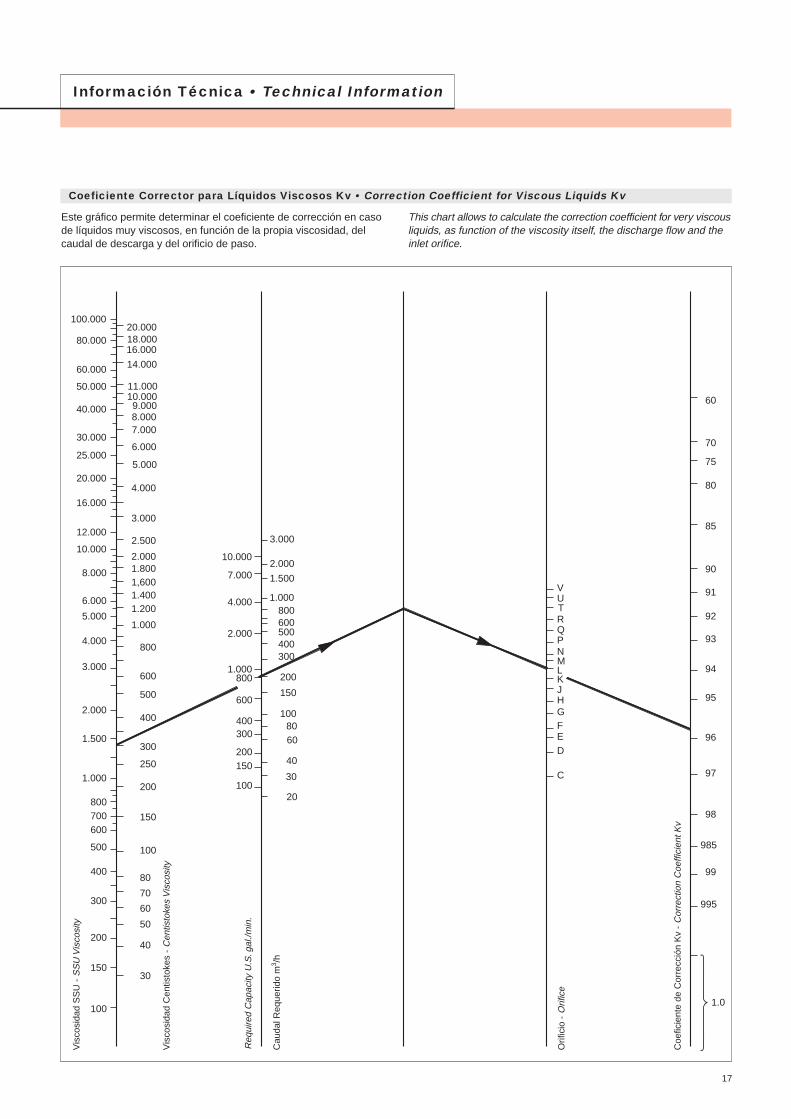
Coeficiente Corrector para Líquidos Viscosos Kv • Correction Coefficient for Viscous Liquids Kv
Información Técnica • Technical Information
Este gráfico permite determinar el coeficiente de corrección en casode líquidos muy viscosos, en función de la propia viscosidad, delcaudal de descarga y del orificio de paso.
This chart allows to calculate the correction coefficient for very viscousliquids, as function of the viscosity itself, the discharge flow and theinlet orifice.
100.000
80.000
60.000
50.000
40.000
30.000
25.000
20.000
16.000
12.000
10.000
8.000
6.000
5.000
4.000
3.000
2.000
1.500
1.000
800700600
500
300
400
100
150
200
20.00018.00016.000
14.000
11.00010.0009.0008.0007.000
6.000
5.000
4.000
3.000
2.500
2.0001.8001,6001.4001.200
1.000
800
600
500
300
400
100
150
250
200
80
70
60
50
40
30
10.000
7.000
4.000
2.000
1.000800
600
400300
200150
100
3.000
2.000
1.500
1.000800600
400500
100
150
300
200
8060
40
30
20
VUTRQPNMLKJHGFED
C
70
75
80
85
90
91
92
93
94
95
96
97
98
985
99
995
60
1.0
Vis
cosi
dad
SS
U -
SS
U V
isco
sity
Vis
cosi
dad
Cen
tisto
kes
- C
entis
toke
s V
isco
sity
Cau
dal R
eque
rido
m3 /h
Orif
icio
- O
rific
e
Coe
ficie
nte
de C
orre
cció
n K
v -
Cor
rect
ion
Coe
ffici
ent K
v
Req
uire
d C
apac
ity U
.S. g
al./m
in.
17
0,51
1,52
2,53
3,54
4,5567891011121314151617181920253035404550556065707580859095100110120130140150160170180190200220240260280300320340
2736455564738392101110129148166185203222241259278296315333352371389482575668761854947104011331226131914121505159816901783187620622248243426202806299231783364354937354107447948515222559459666338
6183104125146168189210232253295338381423466508551593636679721764806849891110413171530174319562169238225942807302032333446365938724085429847235149557560016426685272787704812985559407102581111011961128131366414516
1091471852232612993373754134515266026787548309069821057113312091285136114371512158819682347272631053485386442434623500253815760614065196898727876578415917499331069111450122081296713725144841524216760182771979421311228282434525862
171230290349408468527586646705824943
1061118012991418153616551774189220112130224923672486308036734267486154546048664272357829842390169610
102041079711391119851317214359155471673417921191082029621483226702385826232286073098233356357313810540480
280377475572669766864961
10581156135015451739193421292323251827122907310232963491368538804074504760206993796689399912108851185812831138041477715750167231769618669196412158723533254792742529371313173326335208371543910042992468845077554667
437588740892
1044119513471499165018022105240927123016331936233926422945334836514054435747605063537871938810905124221393915456169731849020007215252304224559260762759329110306273366236696397304276445799488335186754901579356097067038
71696512141463171219612209245827072956345439514449494754455942644069387435793384318928942699241042212910153991788720376228642535327842303303281935307377964028442773452614775050239552166019365170701477512480101850789005595033100010109964
1023137817332088244427993154351038654220493156416352706377738484919499051061611326120371274713458141681487918432219852553829091326443619739750433034685650408539615751461067646206817371726788328593893044100150107255114361121467128573
158821402691324337954346489854506001655376568760986310966120701317314276153801648317587186901979320897220002310328620341373965445171506875620461721672387275578271837888930594822100339105855111372122406
20022698339340894784548061766871756782629654110451243613827152181661018001193922078322174235662495726348277392913036086430424999856954639107086677822847789173498690105646112602119558126514133470140426154338
241632564095493557746614745382939132997211651133301500916688183672004621725234042508326762284413012031799334783515743552519486034368738771338552893923102318110713119109127504135899144294152689
35554791602672618497973210967122021343814673171431961422085245552702629496319673443736908393794184944320467904926151731640847643788790101143113496125848138201150554162907175260187613
615382911042812566147041684218979211172325525393296683394438219424954677051046553215959763872681487242376699809748525089525110903132281153658175036196413
890612000150941818821283243772747130565336593675442942491305531961507676967388480072862619244998638104826111014117203123391129580160522191464
1445419477244992952134543395654458749609546315965369697797428978699830
109874119918129962140007150051160095170139180183190227200272210316
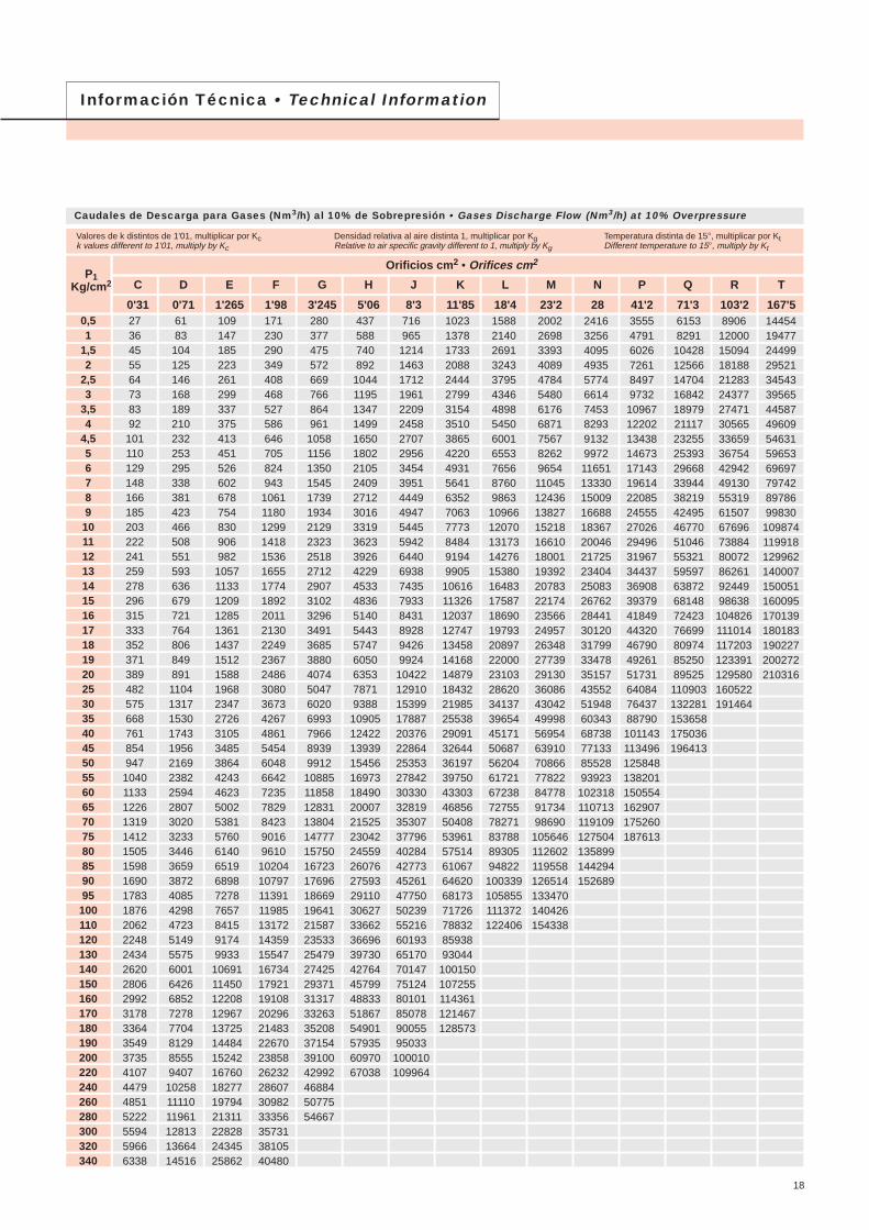
Valores de k distintos de 1'01, multiplicar por Kck values different to 1'01, multiply by Kc
Densidad relativa al aire distinta 1, multiplicar por KgRelative to air specific gravity different to 1, multiply by Kg
Temperatura distinta de 15°, multiplicar por KtDifferent temperature to 15°, multiply by Kt
Orificios cm2 • Orifices cm2P1
Kg/cm2 C
0'31
D
0'71
E
1'265
F
1'98
G
3'245
H
5'06
J
8'3
K
11'85
L
18'4
M
23'2
N
28
P
41'2
Q
71'3
R
103'2
T
167'5
Información Técnica • Technical Information
Caudales de Descarga para Gases (Nm3/h) al 10% de Sobrepresión • Gases Discharge Flow (Nm3/h) at 10% Overpressure
18
0,51
1,52
2,53
3,54
4,5567891011121314151617181920253035404550556065707580859095100110120130140150160170180190200220240260280300320340
0'791'121'371'581'771'942'092'242'372'502'742'963'163'363'543'713'874'034'184'334'474'614'744'885'005'596'136'627'077'507'918'298'669'029'369'6910'0010'3110'6110'9011'1811'7312'2512'7513'2313'7014'1514'5815'0015'4215'8216'5917'3318'0318'7119'3720'0120'62
1'812'563'143'624'054'444'795'125'435'736'276'787'257'688'108'508'879'249'589'9210'2510'5610'8711'1711'4612'8114'0315'1516'2017'1818'1119'0019'8420'6521'4322'1822'9123'6224'3024'9725'6226'8728'0629'2130'3131'3732'4033'4034'3735'3136'2337'9939'6841'3042'8644'3745'8247'23
3'234'565'596'457'227'908'549'139'6810'2111'1812'0712'9113'6914'4315'1415'8116'4617'0817'6818'2618'8219'3619'8920'4122'8225'0027'0028'8630'6232'2733'8535'3536'7938'1839'5240'8242'0843'3044'4845'6447'8749'9952'0454'0055'9057'7359'5061'2362'9164'5467'6970'7073'5976'3779'0581'6484'15
5'057'148'7510'1011'2912'3713'3614'2915'1515'9717'5018'9020'2021'4322'5923'6924'7525'7626'7327'6728'5729'4530'3131'1431'9535'7239'1342'2645'1847'9250'5152'9855'3357'5959'7761'8663'8965'8667'7769'6271'4374'9278'2581'4584'5287'4990'3693'1495'8498'46101'02105'95110'66115'18119'53123'73127'78131'72
8'2811'7114'3416'5618'5120'2821'9023'4124'8326'1828'6830'9733'1135'1237'0238'8340'5542'2143'8045'3446'8348'2749'6751'0352'3658'5464'1269'2674'0478'5382'7886'8290'6894'3997'95101'39104'71107'93111'06114'11117'07122'79128'25133'48138'52143'38148'09152'64157'07161'37165'56173'65181'37188'77195'90
12'9118'2622'3625'8228'8631'6234'1536'5138'7340'8244'7248'3051'6354'7757'7360'5563'2465'8268'3070'7073'0275'2777'4579'5781'6491'2899'99108'00115'46122'46129'08135'38141'40147'18152'73158'10163'28168'31173'18177'93182'55191'46199'98208'14216'00223'58230'91238'02244'92251'63258'17270'77
21'1729'9436'6742'3547'3551'8756'0259'8963'5266'9673'3579'2384'7089'8394'6999'31103'73107'97112'04115'97119'78123'46127'04130'52133'92149'72164'01177'15189'39200'87211'74222'07231'95241'42250'53259'33267'83276'07284'08291'86299'44314'06328'02341'42354'31366'74378'77390'43401'75412'76423'48444'15
30'2342'7552'3660'4667'6074'0579'9885'5090'6995'60104'72113'11120'92128'26135'19141'79148'10154'14159'96165'58171'01176'27181'38186'35191'19213'76234'16252'92270'39286'79302'30317'06331'16344'68357'69370'24382'39394'15405'58416'69427'52448'39468'32487'45505'85523'60540'77557'42573'58
46'9466'3881'3093'88104'96114'98124'19132'77140'82148'44162'60175'63187'76199'15209'92220'17229'96239'35248'38257'10265'53273'70281'64289'36296'87331'91363'59392'73419'84445'31469'40492'31514'20535'20555'40574'89593'75612'02629'76647'02663'83696'23
59'1883'70102'51118'37132'34144'97156'59167'40177'55187'16205'02221'45236'74251'10264'68277'60289'95301'78313'18324'17334'80345'10355'11364'84374'32418'50458'44495'18529'37561'48591'85620'74648'34674'81700'29724'86748'64771'68794'05815'81837'00877'85
71'43101'02123'72142'86159'72174'97188'99202'03214'29225'88247'44267'27285'72303'05319'44335'04349'93364'22377'97391'24404'07416'51428'58440'32451'76505'09553'29597'63638'89677'64714'30749'16782'48814'43845'17874'84903'53931'33958'33
105'10148'64182'05210'21235'02257'45278'08297'28315'31332'37364'09393'26420'42445'92470'04492'98514'90535'93556'16575'68594'56612'86630'63647'91664'74743'20814'13879'36940'08997'11
1051'041102'341151'361198'371243'611287'26
181'89257'23315'05363'78406'72445'54481'24514'47545'67575'19630'09680'58727'57771'70813'44853'15891'08927'47962'48996'261028'931060'601091'351121'251150'381286'171408'931521'811626'891725'57
263'27372'32456'00526'54588'69644'88696'55744'64789'81832'54912'00985'071053'081116'961177'381234'851289'761342'421393'101441'991489'281535'121579'621622'911665'071861'60
427'30604'30740'11854'61955'481046'681130'541208'601281'911351'261480'231598'831709'221812'901910'962004'242093'362178'832261'082340'442417'202491'592563'83
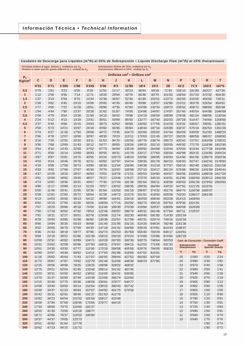
Densidad relativa al agua distinta 1, multiplicar por KgRelative to water specific gravity different to 1, multiply by Kg
Sobrepresión distinta del 25%, multiplicar por KpOverpressure different to 25%°, multiply by Kp
Orificios cm2 • Orifices cm2P1
Kg/cm2 C
0'31
D
0'71
E
1'265
F
1'98
G
3'245
H
5'06
J
8'3
K
11'85
L
18'4
M
23'2
N
28
P
41'2
Q
71'3
R
103'2
T
167'5
Información Técnica • Technical Information
Caudales de Descarga para Líquidos (m3/h) al 25% de Sobrepresión • Liquids Discharge Flow (m3/h) at 25% Overpressure
19
2'241'821'581'411'291'191'121'051'000'950'910'810'840'810'790'760'740'72
0'200'300'400'500'600'700'800'901'001'101'201'301'401'501'601'701'801'90
1'0000'9900'9700'9600'9400'9250'9050'8820'8550'8250'7950'7600'7250'6900'6600'640
25242322212019181716151413121110
Coef. de Corrección • Correction Coeff.
SobrepresiónOverpressure
DensidadSpecific Gravity
% Kp D Kg
0,51
1,52
2,53
3,54
4,5567891011121314151617181920253035404550556065707580859095100110120130140150160170180190200220
20233640525668728387102117133148163178194209224239254270285300315392468541618692769848928994107311471228131213941475156017161895203422252384259227592995319534804091
4653839111912815516419120023426930433937440844347851354858361765268772289710721239141615841762194321252277245826282813300431943379357339304341465850955460593763206859731779699369
8295
14816321322827729234035541647954160366672879085291497610381100116212241286159819112208252328223140346237864056438046825013535256906021636670017734829990789729105781126012220130371419916692
128149232255333356433457532556651749847945104211391236133314301527162517211819191620132501299134563949441749155419592563496856732978468377890694249965
1095912106129901420915227165561762519127204052222426127
21024438041754658471074987391210671228138815481708186720262185234425032663282129813140329940984901566464717239805588819711
10405112361201212859137291459615444163311796019840212902328824956271342888531347334423642342819
3273805936518519111107116713611422166419142164241426632911315934073656390341534399464948965144639176438832
100911128812560138481514216225175211873020051214082276024083254662800630937331983631338915423104504148880521465679566769
53762397210671396149418151915223223322730314035503960436847755182558959966402681272167626803184381048312537144871655218516206022271524838266132874030723328903511637334395034177245938507465445559565638326940273881801798553693162109522
76688913881524199321332592273431873330389844835068565362366818739879808561914197251030310888114661204714966178992068323632264362941432431354613799641032438644695750136533025639959638655867245177746850419113499086105481114472
1190138121552366309533124024424549485170605269617870877896831058611488123911329314193151011599716906178031870623239277923211636694410484567350357550625899863712681097291277848827648757492603101839
150017412718298339024176507453526239651976318777992311068122091334814485156231676117896190402017021316224482358629301350424049446267517565758763494694267438980333858779193398156104355110419116760128406
18102101328036004709504061246460753078689210105931197613357147351610917482188552022821599229792434325726270922846635363422934887255839624646950276630837908978096954103644110954118464
2664309248265298692974169011950511079115771355215587176221965421681237042572327744297653178133812358203785439864418855203462231719128216391911
102267112756123291132105142660152505
461053518352916811992128341559416449191732003523453269743049634014375214102144515480135151055000585156198965509689887248590050107695124450142190159060
6672774512089132701735718576225712380927752289993394639042441404923254308593756443269495745567960784694897239481899854104916130339155878
10829125701962121539281723015036635386434504347068550976336871643799068814596369104577112794121009129207137464145626153896162069
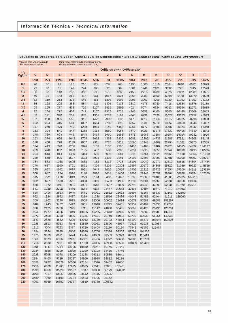
Valores para vapor saturadoSaturated steam values
Para vapor recalentado, multiplicar por KsFor superheated steam, multiply by Ks
Orificios cm2 • Orifices cm2P1
Kg/cm2 C
0'31
D
0'71
E
1'265
F
1'98
G
3'245
H
5'06
J
8'3
K
11'85
L
18'4
M
23'2
N
28
P
41'2
Q
71'3
R
103'2
T
167'5
Información Técnica • Technical Information
Caudales de Descarga para Vapor (Kg/h) al 10% de Sobrepresión • Steam Discharge Flow (Kg/h) at 10% Overpressure
20
Vapor Recalentado °C • Superheated Steam °C
KsP1
(Kg/cm2)
T
(°C)0,99 0,97 0,93 0,89 0,85 0,81 0,77
DensidadSpecificGravity
Kg °C Kt K Kc
0'20
0'30
0'40
0'50
0'60
0'70
0'80
0'82
0'84
0'86
0'88
0'90
0'92
0'94
0'96
0'98
1'00
1'02
1'04
1'06
1'08
1'10
1'12
1'14
1'16
1'18
1'20
1'25
1'30
1'35
1'40
1'45
1'50
1'55
1'60
1'65
1'70
1'75
1'80
1'90
2'00
2'10
2'20
2'30
2'40
2'50
2'240
1'825
1'580
1'414
1'320
1'195
1'117
1'104
1'091
1'078
1'066
1'055
1'043
1'031
1'021
1'010
1'000
0'990
0'981
0'971
0'962
0'953
0'945
0'937
0'928
0'921
0'913
0'895
0'877
0'861
0'845
0'830
0'817
0'803
0'791
0'779
0'768
0'756
0'745
0'725
0'707
0'690
0'674
0'659
0'645
0'633
-29
-23
-18
-12
-7
-1
4
10
15
21
27
32
38
43
49
54
60
66
71
82
93
104
116
127
138
149
160
171
182
193
204
260
316
371
427
480
538
1'087
1'075
1'063
1'052
1'041
1'030
1'020
1'010
1'000
0'9905
0'9813
0'9723
0'9636
0'9552
0'9469
0'9388
0'9310
0'9233
0'9158
0'9014
0'8876
0'8746
0'8619
0'8498
0'8383
0'8272
0'8165
0'8062
0'7963
0'7868
0'7776
0'7360
0'7005
0'6695
0'6425
0'6183
0'5968
1'01
1'02
1'04
1'06
1'08
1'10
1'12
1'14
1'16
1'18
1'20
1'22
1'24
1'26
1'28
1'30
1'32
1'34
1'36
1'38
1'40
1'42
1'44
1'46
1'48
1'50
1'52
1'54
1'56
1'58
1'60
1'62
1'64
1'66
1'68
1'70
2'00
2'20
1'000
1'010
1'016
1'022
1'029
1'033
1'044
1'051
1'057
1'063
1'070
1'076
1'083
1'089
1'095
1'102
1'108
1'113
1'118
1'124
1'130
1'136
1'141
1'146
1'152
1'157
1'162
1'168
1'172
1'177
1'182
1'187
1'193
1'197
1'202
1'207
1'270
1'308
0'5
1
1'5
2
2'5
3
3'5
4
4'5
5
6
7
8
9
10
11
12
13
14
15
16
17
18
19
20
25
30
35
40
45
50
55
60
65
70
111
119'5
127
133
138
143
147
151
154'5
158
164
169'5
174'5
179
183
187
190'5
194
197'5
200'5
203'5
206
209
211'5
214
225
234'5
243
250'5
257'5
264
270
275
281
286
136
131
142
146
151
156
161
164
168
171
176
182
186
191
166
170
174
177
179
183
185
188
190
193
198
202
206
210
214
217
220
224
227
229
232
234
236
239
241
251
259
267
274
280
286
291
296
301
306
238
239
240
240'5
241
242
243
244
245
246
248
251
253
256
258
261
263
265
267
268'5
270'5
272
274
275'5
277'5
286
292
298
305
310
315
320
324
329
333
299
298
296
295
294
293'5
293
292'5
292
291'5
295
290'5
291
292
293'5
295'5
298
300
301'5
303
304'5
306
307'5
309
310'5
317
323
329
334
340
346
351
355
360
364
354'5
353
351
350
349'5
348'5
347'5
346'5
346
345
344'5
344
344
344'5
345'5
346
346'5
347
348
349
350
351
352
352'5
353
359
365'5
371
377
382
387
391
396
400
404
417'5
416'5
416
414'5
413'5
412
411
410
410
410
409'5
409
408
407'5
407
407
407
406'7
406'5
406
406
406
406
406'5
406'7
410
415
420
424
429
433
437
441
441
449
493'5
493
492
491'8
491'5
491
491
490'8
490'5
490'5
490'2
490
489'5
489
489
489
488'5
488
488
488
488
487'8
487'8
487'8
487'8
491
493
496
500
503
506
510
512
515
518
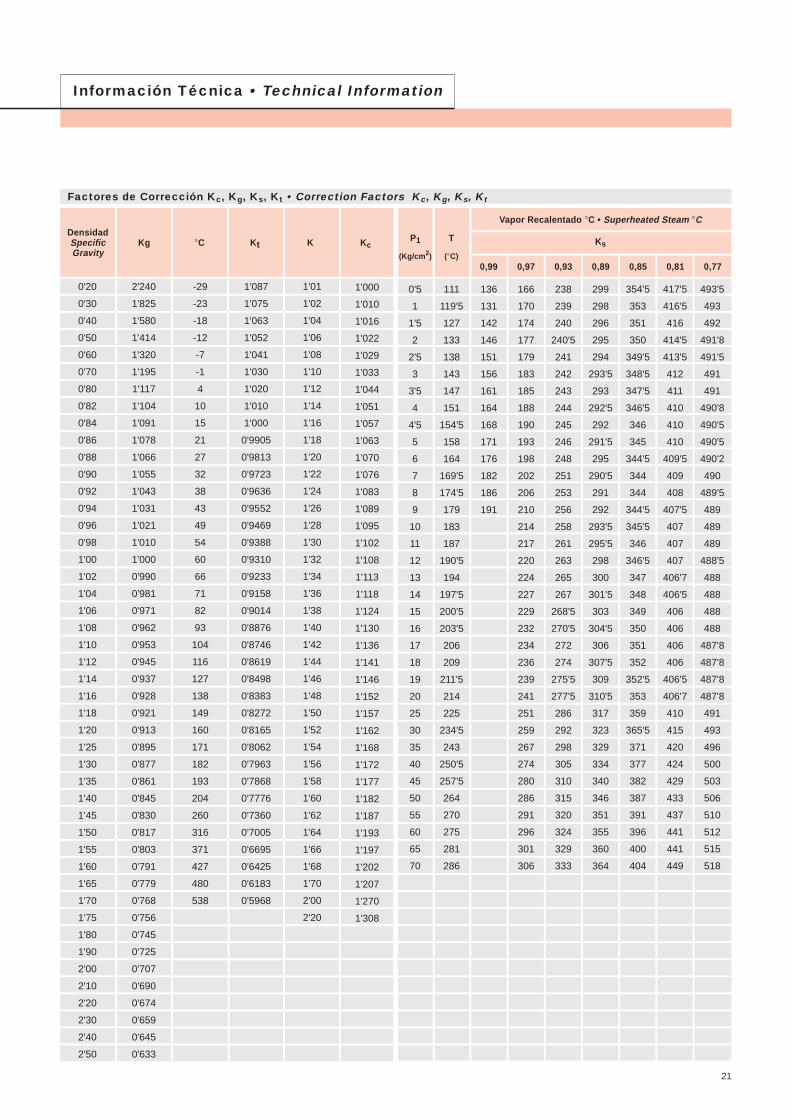
Información Técnica • Technical Information
Factores de Corrección Kc, Kg, Ks, Kt • Correction Factors Kc, Kg, Ks, Kt
21
Información Técnica • Technical Information
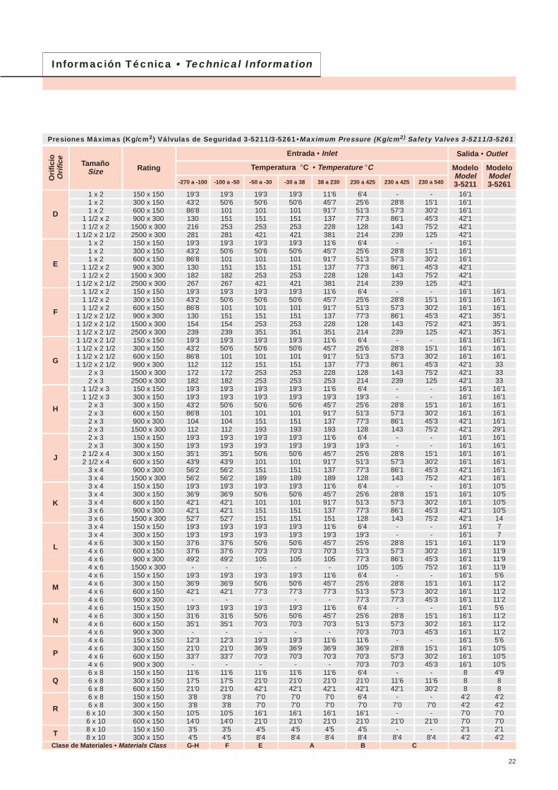
Presiones Máximas (Kg/cm2) Válvulas de Seguridad 3-5211/3-5261•Maximum Pressure (Kg/cm2) Safety Valves 3-5211/3-5261
22
T
Entrada • Inlet
Temperatura °C • Temperature °C
Ori
fici
oO
rifi
ce TamañoSize Rating
-270 a -100 -100 a -50 -50 a -30 -30 a 38 38 a 230 230 a 425 230 a 425 230 a 540
Salida • Outlet
ModeloModel3-5211
ModeloModel3-5261
1 x 21 x 21 x 2
1 1/2 x 21 1/2 x 2
1 1/2 x 2 1/21 x 21 x 21 x 2
1 1/2 x 21 1/2 x 2
1 1/2 x 2 1/21 1/2 x 21 1/2 x 21 1/2 x 2
1 1/2 x 2 1/21 1/2 x 2 1/21 1/2 x 2 1/21 1/2 x 2 1/21 1/2 x 2 1/21 1/2 x 2 1/21 1/2 x 2 1/2
2 x 32 x 3
1 1/2 x 31 1/2 x 3
2 x 32 x 32 x 32 x 32 x 32 x 3
2 1/2 x 42 1/2 x 4
3 x 43 x 43 x 43 x 43 x 43 x 63 x 63 x 43 x 44 x 64 x 64 x 64 x 64 x 64 x 64 x 64 x 64 x 64 x 64 x 64 x 64 x 64 x 64 x 64 x 66 x 86 x 86 x 86 x 86 x 86 x 106 x 108 x 108 x 10
D
E
F
G
H
J
K
L
M
N
P
Q
R
Clase de Materiales • Materials Class G-H F E A B C
150 x 150300 x 150600 x 150900 x 300
1500 x 3002500 x 300150 x 150300 x 150600 x 150900 x 300
1500 x 3002500 x 300150 x 150300 x 150600 x 150900 x 300
1500 x 3002500 x 300150 x 150300 x 150600 x 150900 x 300
1500 x 3002500 x 300150 x 150300 x 150300 x 150600 x 150900 x 300
1500 x 300150 x 150300 x 150300 x 150600 x 150900 x 300
1500 x 300150 x 150300 x 150600 x 150900 x 300
1500 x 300150 x 150300 x 150300 x 150600 x 150900 x 300
1500 x 300150 x 150300 x 150600 x 150900 x 300150 x 150300 x 150600 x 150900 x 300150 x 150300 x 150600 x 150900 x 300150 x 150300 x 150600 x 150150 x 150300 x 150300 x 150600 x 150150 x 150300 x 150
19'343'286'813021628119'343'286'813018226719'343'286'813015423919'343'286'811217218219'319'343'286'810411219'319'335'143'956'256'219'336'942'142'152'719'319'337'637'649'2
-19'336'942'1
-19'331'635'1
-12'321'033'7
-11'617'521'03'83'810'514'03'54'5
19'350'610115125328119'350'610115118226719'350'610115115423919'350'610111217218219'319'350'610110411219'319'335'143'956'256'219'336'942'142'152'719'319'337'637'649'2
-19'336'942'1
-19'331'635'1
-12'321'033'7
-11'617'521'03'83'810'514'03'54'5
19'350'610115125342119'350'610115125342119'350'610115125335119'350'610115125325319'319'350'610115119319'319'350'610115118919'350'610115115119'319'350'670'3105
-19'350'677'3
-19'350'670'3
-19'336'970'3
-11'621'042'17'07'016'121'04'58'4
11'645'791'713722838111'645'791'713722838111'645'791'713722835111'645'791'713722825311'619'345'791'713719311'619'345'791'713718911'645'791'713715111'619'345'770'3105
-11'645'777'3
-11'645'770'3
-11'636'970'3
-11'621'042'17'07'016'121'04'58'4
19'350'610115125342119'350'610115125342119'350'610115125335119'350'610115125325319'319'350'610115119319'319'350'610115118919'350'610115115119'319'350'670'3105
-19'350'677'3
-19'350'670'3
-19'336'970'3
-11'621'042'17'07'016'121'04'58'4
6'425'651'377'31282146'425'651'377'31282146'425'651'377'31282146'425'651'377'31282146'419'325'651'377'31286'419'325'651'377'31286'425'651'377'31286'419'325'651'377'31056'425'651'377'36'425'651'370'311'636'970'370'36'421'042'16'47'016'121'04'58'4
-28'857'386'1143239
-28'857'386'1143239
-28'857'386'1143239
-28'857'386'1143239
--
28'857'386'1143
--
28'857'386'1143
-28'857'386'1143
--
28'857'386'1105
-28'857'377'3
-28'857'370'3
-28'857'370'3
-11'642'1
-7'0-
21'0-
8'4
-15'130'245'375'2125
-15'130'245'375'2125
-15'130'245'375'2125
-15'130'245'375'2125
--
15'130'245'375'2
--
15'130'245'375'2
-15'130'245'375'2
--
15'130'245'375'2
-15'130'245'3
-15'130'245'3
-15'130'245'3
-11'630'2
-7'0-
21'0-
8'4
16'116'116'142'142'142'116'116'116'142'142'142'116'116'116'142'142'142'116'116'116'142'142'142'116'116'116'116'142'142'116'116'116'116'142'142'116'116'116'142'142'116'116'116'116'116'116'116'116'116'116'116'116'116'116'116'116'116'116'1
888
4'24'27'07'02'14'2
16'116'116'135'135'135'116'116'116'1333333
16'116'116'116'116'129'116'116'116'116'116'116'110'510'510'510'51477
11'911'911'911'95'611'211'211'25'611'211'211'25'610'510'510'54'988
4'24'27'07'02'14'2
OrificioOrifice
E
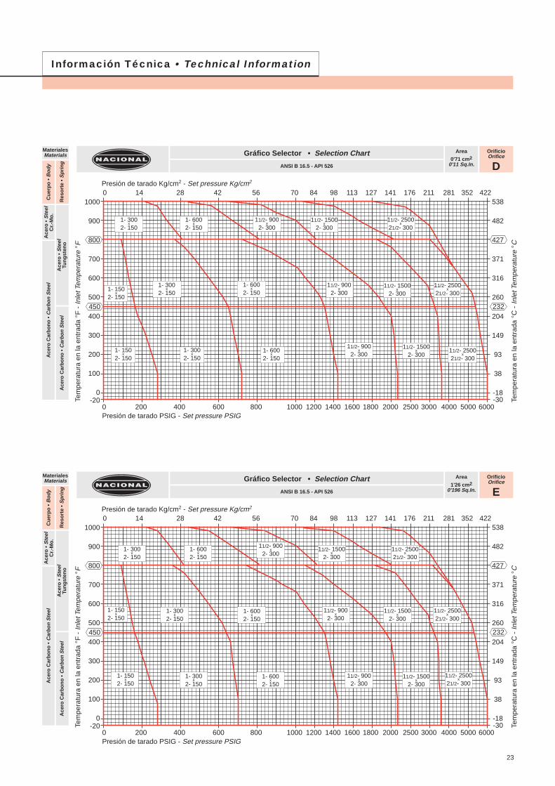
Area
1'26 cm20'196 Sq.In.
Gráfico Selector • Selection Chart
ANSI B 16.5 - API 526
MaterialesMaterials
Ace
ro •
Ste
elC
r.-M
o.
Ace
ro •
Ste
elTu
ng
sten
oA
cero
Car
bo
no
• C
arb
on
Ste
el
Cu
erp
o •
Bo
dy
Res
ort
e •
Sp
rin
g
Ace
ro C
arb
on
o •
Car
bo
n S
teel
OrificioOrifice
D
Area
0'71 cm20'11 Sq.In.
Gráfico Selector • Selection Chart
ANSI B 16.5 - API 526
MaterialesMaterials
Ace
ro •
Ste
elC
r.-M
o.
Ace
ro •
Ste
elTu
ng
sten
oA
cero
Car
bo
no
• C
arb
on
Ste
el
Cu
erp
o •
Bo
dy
Res
ort
e •
Sp
rin
g
Ace
ro C
arb
on
o •
Car
bo
n S
teel
Información Técnica • Technical Information
Presión de tarado Kg/cm2 - Set pressure Kg/cm2
538
482
427
371
316
260
204
149
93
38
-18-30
232
Tem
pera
tura
en
la e
ntra
da °
C -
Inle
t Tem
pera
ture
°C
Presión de tarado PSIG - Set pressure PSIG
1000
900
800
700
600
500
400
300
200
100
0-20
450
Tem
pera
tura
en
la e
ntra
da °
F -
Inle
t Tem
pera
ture
°F
0 200 400 600 800 1000 1200 1400 1600 1800 2000 2500 3000 4000 5000 6000
0 14 28 42 56 70 84 98 113 127 141 176 211 281 352 422
23
1- 300x
2- 1501- 600
x2- 150
11/2- 900x
2- 30011/2- 1500
x2- 300
11/2- 2500x
21/2- 300
1- 150x
2- 150
1- 300x
2- 1501- 600
x2- 150
11/2- 1500x
2- 30011/2- 2500
x21/2- 300
11/2- 900x
2- 300
1- 150x
2- 1501- 300
x2- 150
1- 600x
2- 150
11/2- 1500x
2- 30011/2- 2500
x21/2- 300
11/2- 900x
2- 300
1- 300x
2- 1501- 600
x2- 150
11/2- 900x
2- 30011/2- 1500
x2- 300
11/2- 2500x
21/2- 300
1- 150x
2- 1501- 300
x2- 150
1- 600x
2- 15011/2- 1500
x2- 300
11/2- 2500x
21/2- 30011/2- 900
x2- 300
1- 150x
2- 1501- 300
x2- 150
1- 600x
2- 15011/2- 1500
x2- 300
11/2- 2500x
21/2- 30011/2- 900
x2- 300
OrificioOrifice
G
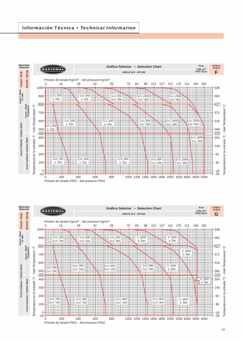
Area
3'25 cm20'503 Sq.In.
Gráfico Selector • Selection Chart
ANSI B 16.5 - API 526
MaterialesMaterials
Ace
ro •
Ste
elC
r.-M
o.
Ace
ro •
Ste
elTu
ng
sten
oA
cero
Car
bo
no
• C
arb
on
Ste
el
Cu
erp
o •
Bo
dy
Res
ort
e •
Sp
rin
g
Ace
ro C
arb
on
o •
Car
bo
n S
teel
OrificioOrifice
F
Area
1'98 cm20'307 Sq.In.
Gráfico Selector • Selection Chart
ANSI B 16.5 - API 526
MaterialesMaterials
Ace
ro •
Ste
elC
r.-M
o.
Ace
ro •
Ste
elTu
ng
sten
oA
cero
Car
bo
no
•C
arb
on
Ste
el
Cu
erp
o •
Bo
dy
Res
ort
e •
Sp
rin
g
Ace
ro C
arb
on
o •
Car
bo
n S
teel
Información Técnica • Technical Information
Presión de tarado Kg/cm2 - Set pressure Kg/cm2
538
482
427
371
316
260
204
149
93
38
-18-30
232
Tem
pera
tura
en
la e
ntra
da °
C -
Inle
t Tem
pera
ture
°C
Presión de tarado PSIG - Set pressure PSIG
1000
900
800
700
600
500
400
300
200
100
0-20
450
Tem
pera
tura
en
la e
ntra
da °
F -
Inle
t Tem
pera
ture
°F
0 200 400 600 800 1000 1200 1400 1600 1800 2000 2500 3000 4000 5000
0 14 28 42 56 70 84 98 113 127 141 176 211 281 352
Presión de tarado Kg/cm2 - Set pressure Kg/cm2
538
482
427
371
316
260
204
149
93
38
-18-30
232
Tem
pera
tura
en
la e
ntra
da °
C -
Inle
t Tem
pera
ture
°C
Presión de tarado PSIG - Set pressure PSIG
1000
900
800
700
600
500
400
300
200
100
0-20
450
Tem
pera
tura
en
la e
ntra
da °
F -
Inle
t Tem
pera
ture
°F
0 200 400 600 800 1000 1200 1400 1600 1800 2000 2500 3000 3500 4000
0 14 28 42 56 70 84 98 113 127 141 176 211 246 281
24
11/2- 300x
2- 15011/2- 600
x2- 150
11/2- 900x
21/2- 30011/2- 1500
x21/2- 300
11/2- 2500x
21/2- 300
11/2- 150x
2- 150
11/2- 300x
2- 15011/2- 600
x2- 150
11/2- 1500x
21/2- 30011/2- 2500
x21/2- 300
11/2- 900x
21/2- 300
11/2- 150x
2- 15011/2- 300
x2- 150
11/2- 600x
2- 15011/2- 1500
x21/2- 300
11/2- 2500x
21/2- 300
11/2- 900x
21/2- 300
11/2- 300x
21/2- 15011/2- 600
x21/2- 150
11/2- 900x
21/2- 3002- 1500
x3- 300
2- 2500x
3- 300
11/2- 150x
21/2- 150
11/2- 300x
21/2- 15011/2- 600
x21/2- 150
2- 1500x
3- 30011/2- 900
x21/2- 300
11/2- 150x
21/2- 15011/2- 300
x21/2- 150
11/2- 600x
21/2- 150
2- 2500x
3- 300
11/2- 900x
21/2- 300
2- 2500x
3- 300
2- 1500x
3- 300
OrificioOrifice
J
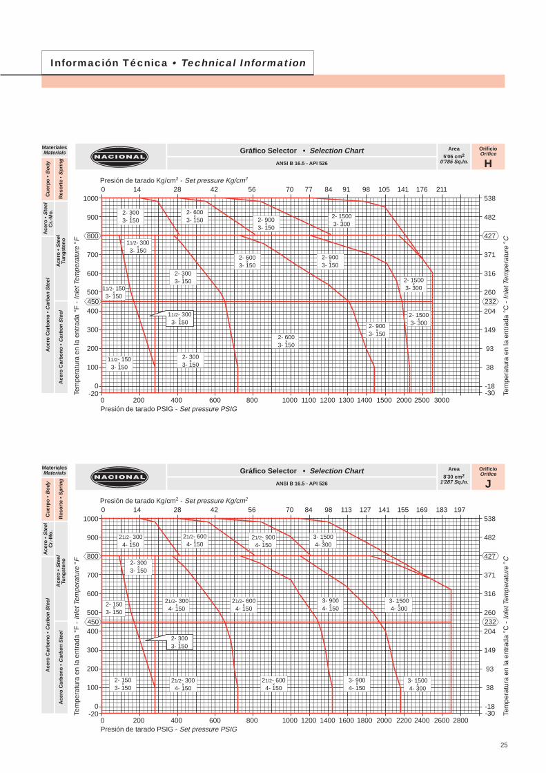
Area
8'30 cm21'287 Sq.In.
Gráfico Selector • Selection Chart
ANSI B 16.5 - API 526
MaterialesMaterials
Ace
ro •
Ste
elC
r.-M
o.
Ace
ro •
Ste
elTu
ng
sten
oA
cero
Car
bo
no
• C
arb
on
Ste
el
Cu
erp
o •
Bo
dy
Res
ort
e •
Sp
rin
g
Ace
ro C
arb
on
o •
Car
bo
n S
teel
OrificioOrifice
H
Area
5'06 cm20'785 Sq.In.
Gráfico Selector • Selection Chart
ANSI B 16.5 - API 526
MaterialesMaterials
Ace
ro •
Ste
elC
r.-M
o.
Ace
ro •
Ste
elTu
ng
sten
oA
cero
Car
bo
no
• C
arb
on
Ste
el
Cu
erp
o •
Bo
dy
Res
ort
e •
Sp
rin
g
Ace
ro C
arb
on
o •
Car
bo
n S
teel
Información Técnica • Technical Information
Presión de tarado Kg/cm2 - Set pressure Kg/cm2
538
482
427
371
316
260
204
149
93
38
-18-30
232
Tem
pera
tura
en
la e
ntra
da °
C -
Inle
t Tem
pera
ture
°C
Presión de tarado PSIG - Set pressure PSIG
1000
900
800
700
600
500
400
300
200
100
0-20
450
Tem
pera
tura
en
la e
ntra
da °
F -
Inle
t Tem
pera
ture
°F
0 200 400 600 800 1000 1100 1200 1300 1400 1500 2000 2500 3000
0 14 28 42 56 70 77 84 91 98 105 141 176 211
Presión de tarado Kg/cm2 - Set pressure Kg/cm2
538
482
427
371
316
260
204
149
93
38
-18-30
232
Tem
pera
tura
en
la e
ntra
da °
C -
Inle
t Tem
pera
ture
°C
Presión de tarado PSIG - Set pressure PSIG
1000
900
800
700
600
500
400
300
200
100
0-20
450
Tem
pera
tura
en
la e
ntra
da °
F -
Inle
t Tem
pera
ture
°F
0 200 400 600 800 1000 1200 1400 1600 1800 2000 2200 2400 2600 2800
0 14 28 42 56 70 84 98 113 127 141 155 169 183 197
25
2- 300x
3- 1502- 600
x3- 150 2- 900
x3- 150
2- 1500x
3- 300
11/2- 150x
3- 150
2- 300x
3- 150
2- 600x
3- 150
2- 1500x
3- 300
2- 900x
3- 150
11/2- 150x
3- 150
2- 300x
3- 150
2- 600x
3- 150
2- 1500x
3- 3002- 900x
3- 150
11/2- 300x
3- 150
11/2- 300x
3- 150
21/2- 300x
4- 15021/2- 600
x4- 150
21/2- 900x
4- 1503- 1500
x4- 300
2- 150x
3- 150
21/2- 300x
4- 15021/2- 600
x4- 150
3- 1500x
4- 3003- 900
x4- 150
2- 150x
3- 15021/2- 300
x4- 150
21/2- 600x
4- 1503- 1500
x4- 300
3- 900x
4- 150
2- 300x
3- 150
2- 300x
3- 150
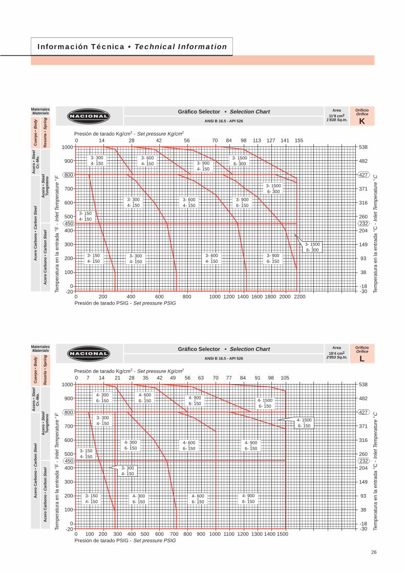
OrificioOrifice
L
Area
18'4 cm22'853 Sq.In.
Gráfico Selector • Selection Chart
ANSI B 16.5 - API 526
MaterialesMaterials
Ace
ro •
Ste
elC
r.-M
o.
Ace
ro •
Ste
elTu
ng
sten
oA
cero
Car
bo
no
• C
arb
on
Ste
el
Cu
erp
o •
Bo
dy
Res
ort
e •
Sp
rin
g
Ace
ro C
arb
on
o •
Car
bo
n S
teel
OrificioOrifice
K
Area
11'9 cm21'838 Sq.In.
Gráfico Selector • Selection Chart
ANSI B 16.5 - API 526
MaterialesMaterials
Ace
ro •
Ste
elC
r.-M
o.
Ace
ro •
Ste
elTu
ng
sten
oA
cero
Car
bo
no
• C
arb
on
Ste
el
Cu
erp
o •
Bo
dy
Res
ort
e •
Sp
rin
g
Ace
ro C
arb
on
o •
Car
bo
n S
teel
Información Técnica • Technical Information
Presión de tarado Kg/cm2 - Set pressure Kg/cm2
538
482
427
371
316
260
204
149
93
38
-18-30
232
Tem
pera
tura
en
la e
ntra
da °
C -
Inle
t Tem
pera
ture
°C
Presión de tarado PSIG - Set pressure PSIG
1000
900
800
700
600
500
400
300
200
100
0-20
450
Tem
pera
tura
en
la e
ntra
da °
F -
Inle
t Tem
pera
ture
°F
0 200 400 600 800 1000 1200 1400 1600 1800 2000 2200
0 14 28 42 56 70 84 98 113 127 141 155
Presión de tarado Kg/cm2 - Set pressure Kg/cm2
538
482
427
371
316
260
204
149
93
38
-18-30
232
Tem
pera
tura
en
la e
ntra
da °
C -
Inle
t Tem
pera
ture
°C
Presión de tarado PSIG - Set pressure PSIG
1000
900
800
700
600
500
400
300
200
100
0-20
450
Tem
pera
tura
en
la e
ntra
da °
F -
Inle
t Tem
pera
ture
°F
0 100 200 300 400 500 600 700 800 900 1000 1100 1200 1300 1400 1500
0 7 14 21 28 35 42 49 56 63 70 77 84 91 98 105
26
3- 300x
4- 1503- 600
x4- 150 3- 900
x4- 150
3- 1500x
6- 300
3- 300x
4- 1503- 600
x4- 150
3- 1500x
6- 300
3- 900x
6- 150
3- 150x
4- 1503- 300
x4- 150
3- 600x
4- 1503- 900
x6- 150
3- 1500x
6- 300
3- 150x
4- 150
4- 300x
6- 1504- 600
x6- 150
4- 900x
6- 1504- 1500
x6- 150
4- 300x
6- 1504- 600
x6- 150
4- 1500x
6- 150
4- 900x
6- 150
3- 150x
4- 1504- 300
x6- 150
4- 600x
6- 1504- 900
x6- 150
3- 300x
4- 150
3- 300x
4- 150
3- 150x
4- 150
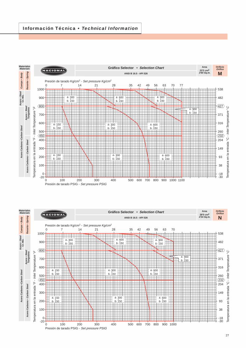
OrificioOrifice
N
Area
28'0 cm24'34 Sq.In.
Gráfico Selector • Selection Chart
ANSI B 16.5 - API 526
MaterialesMaterials
Ace
ro •
Ste
elC
r.-M
o.
Ace
ro •
Ste
elTu
ng
sten
oA
cero
Car
bo
no
• C
arb
on
Ste
el
Cu
erp
o •
Bo
dy
Res
ort
e •
Sp
rin
g
Ace
ro C
arb
on
o •
Car
bo
n S
teel
OrificioOrifice
M
Area
23'2 cm23'60 Sq.In.
Gráfico Selector • Selection Chart
ANSI B 16.5 - API 526
MaterialesMaterials
Ace
ro •
Ste
elC
r.-M
o.
Ace
ro •
Ste
elTu
ng
sten
oA
cero
Car
bo
no
• C
arb
on
Ste
el
Cu
erp
o •
Bo
dy
Res
ort
e •
Sp
rin
g
Ace
ro C
arb
on
o •
Car
bo
n S
teel
Información Técnica • Technical Information
Presión de tarado Kg/cm2 - Set pressure Kg/cm2
538
482
427
371
316
260
204
149
93
38
-18-30
232
Tem
pera
tura
en
la e
ntra
da °
C -
Inle
t Tem
pera
ture
°C
Presión de tarado PSIG - Set pressure PSIG
1000
900
800
700
600
500
400
300
200
100
0-20
450
Tem
pera
tura
en
la e
ntra
da °
F -
Inle
t Tem
pera
ture
°F
0 100 200 300 400 500 600 700 800 900 1000 1100
0 7 14 21 28 35 42 49 56 63 70 77
Presión de tarado Kg/cm2 - Set pressure Kg/cm2
538
482
427
371
316
260
204
149
93
38
-18-30
232
Tem
pera
tura
en
la e
ntra
da °
C -
Inle
t Tem
pera
ture
°C
Presión de tarado PSIG - Set pressure PSIG
1000
900
800
700
600
500
400
300
200
100
0-20
450
Tem
pera
tura
en
la e
ntra
da °
F -
Inle
t Tem
pera
ture
°F
0 100 200 300 400 500 600 700 800 900 1000
0 7 14 21 28 35 42 49 56 63 70
27
4- 300x
6- 1504- 600
x6- 150
4- 900x
6- 150
4- 300x
6- 150
4- 900x
6- 150
4- 600x
6- 150
4- 150x
6- 1504- 300
x6- 150
4- 600x
6- 150
4- 150x
6- 150
4- 300x
6- 150
4- 600x
6- 1504- 900
x6- 150
4- 300x
6- 150
4- 900x
6- 150
4- 600x
6- 150
4- 150x
6- 1504- 300
x6- 150
4- 600x
6- 150
4- 150x
6- 150
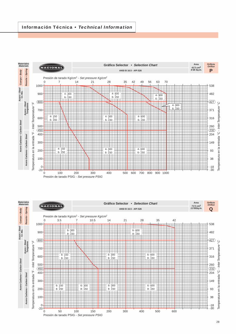
OrificioOrifice
Q
Area
71'2 cm211'05Sq.In.
Gráfico Selector • Selection Chart
ANSI B 16.5 - API 526
MaterialesMaterials
Ace
ro •
Ste
elC
r.-M
o.
Ace
ro •
Ste
elTu
ng
sten
oA
cero
Car
bo
no
• C
arb
on
Ste
el
Cu
erp
o •
Bo
dy
Res
ort
e •
Sp
rin
g
Ace
ro C
arb
on
o •
Car
bo
n S
teel
OrificioOrifice
P
Area
41'2 cm26'38 Sq.In.
Gráfico Selector • Selection Chart
ANSI B 16.5 - API 526
MaterialesMaterials
Ace
ro •
Ste
elC
r.-M
o.
Ace
ro •
Ste
elTu
ng
sten
oA
cero
Car
bo
no
• C
arb
on
Ste
el
Cu
erp
o •
Bo
dy
Res
ort
e •
Sp
rin
g
Ace
ro C
arb
on
o •
Car
bo
n S
teel
Información Técnica • Technical Information
Presión de tarado Kg/cm2 - Set pressure Kg/cm2
538
482
427
371
316
260
204
149
93
38
-18-30
232
Tem
pera
tura
en
la e
ntra
da °
C -
Inle
t Tem
pera
ture
°C
Presión de tarado PSIG - Set pressure PSIG
1000
900
800
700
600
500
400
300
200
100
0-20
450
Tem
pera
tura
en
la e
ntra
da °
F -
Inle
t Tem
pera
ture
°F
0 100 200 300 400 500 600 700 800 900 1000
0 7 14 21 28 35 42 49 56 63 70
Presión de tarado Kg/cm2 - Set pressure Kg/cm2
538
482
427
371
316
260
204
149
93
38
-18-30
232
Tem
pera
tura
en
la e
ntra
da °
C -
Inle
t Tem
pera
ture
°C
Presión de tarado PSIG - Set pressure PSIG
1000
900
800
700
600
500
400
300
200
100
0-20
450
Tem
pera
tura
en
la e
ntra
da °
F -
Inle
t Tem
pera
ture
°F
0 50 100 150 200 300 400 500 600
0 3.5 7 10.5 14 21 28 35 42
6- 300x
8- 1506- 600
x8- 150
6- 300x
8- 150
6- 300x
8- 1506- 600
x8- 150
6- 150x
8- 1506- 300
x8- 150
6- 600x
8- 150
6- 150x
8- 150
28
4- 300x
6- 1504- 600
x6- 150
4- 900x
6- 150
4- 300x
6- 1504- 600
x6- 150
4- 150x
6- 1504- 300
x6- 150
4- 600x
6- 150
4- 150x
6- 150
4- 900x
6- 150
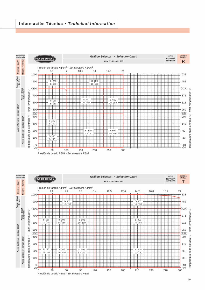
OrificioOrifice
T
Area
167'7 cm226'0 Sq.In.
Gráfico Selector • Selection Chart
ANSI B 16.5 - API 526
MaterialesMaterials
Ace
ro •
Ste
elC
r.-M
o.
Ace
ro •
Ste
elTu
ng
sten
oA
cero
Car
bo
no
• C
arb
on
Ste
el
Cu
erp
o •
Bo
dy
Res
ort
e •
Sp
rin
g
Ace
ro C
arb
on
o •
Car
bo
n S
teel
OrificioOrifice
R
Area
103'2 cm216'0 Sq.In.
Gráfico Selector • Selection Chart
ANSI B 16.5 - API 526
MaterialesMaterials
Ace
ro •
Ste
elC
r.-M
o.
Ace
ro •
Ste
elTu
ng
sten
oA
cero
Car
bo
no
• C
arb
on
Ste
el
Cu
erp
o •
Bo
dy
Res
ort
e •
Sp
rin
g
Ace
ro C
arb
on
o •
Car
bo
n S
teel
Información Técnica • Technical Information
Presión de tarado Kg/cm2 - Set pressure Kg/cm2
538
482
427
371
316
260
204
149
93
38
-18-30
232
Tem
pera
tura
en
la e
ntra
da °
C -
Inle
t Tem
pera
ture
°C
Presión de tarado PSIG - Set pressure PSIG
1000
900
800
700
600
500
400
300
200
100
0-20
450
Tem
pera
tura
en
la e
ntra
da °
F -
Inle
t Tem
pera
ture
°F
0 50 100 150 200 250 300
0 3.5 7 10.5 14 17.5 21
Presión de tarado Kg/cm2 - Set pressure Kg/cm2
538
482
427
371
316
260
204
149
93
38
-18-30
232
Tem
pera
tura
en
la e
ntra
da °
C -
Inle
t Tem
pera
ture
°C
Presión de tarado PSIG - Set pressure PSIG
1000
900
800
700
600
500
400
300
200
100
0-20
450
Tem
pera
tura
en
la e
ntra
da °
F -
Inle
t Tem
pera
ture
°F
0 30 60 90 120 150 180 210 240 270 300
0 2.1 4.2 6.3 8.4 10.5 12.6 14.7 16.8 18.9 21
29
6- 300x
8- 1508- 600
x10- 150
6- 300x
10- 1506- 600
x10- 150
6- 150x
8- 150
6- 300x
10- 1506- 600
x10- 150
6- 150x
8- 150
6- 300x
8- 150
8- 300x
10- 150
8- 300x
10- 1508- 300
x10- 150
8- 300x
10- 150
8- 300x
10- 1508- 300
x10- 150
8- 150x
10- 150
8- 150x
10- 150
8- 300x
10- 150
8- 300x
10- 150
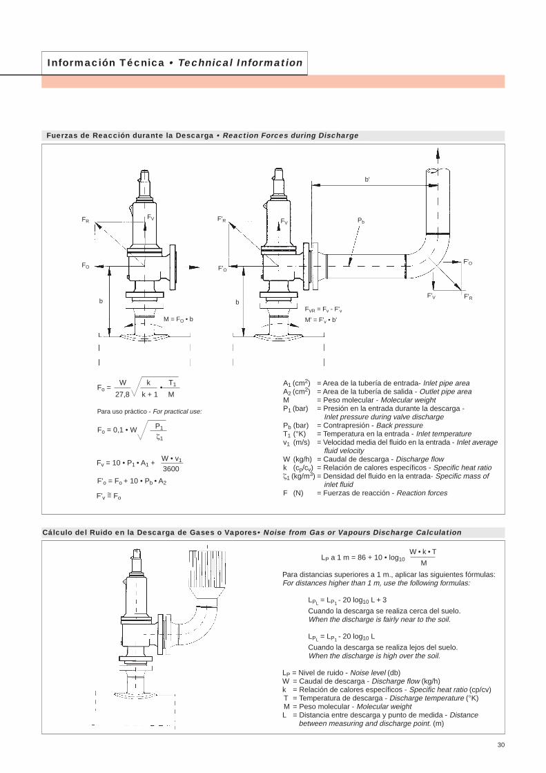
Información Técnica • Technical Information
M = FO • b
A1 (cm2) = Area de la tubería de entrada- Inlet pipe areaA2 (cm2) = Area de la tubería de salida - Outlet pipe areaM = Peso molecular - Molecular weightP1 (bar) = Presión en la entrada durante la descarga -
Inlet pressure during valve dischargePb (bar) = Contrapresión - Back pressureT1 (°K) = Temperatura en la entrada - Inlet temperaturev1 (m/s) = Velocidad media del fluido en la entrada - Inlet average
fluid velocityW (kg/h) = Caudal de descarga - Discharge flowk (cp/cv) = Relación de calores específicos - Specific heat ratioζ1 (kg/m3) = Densidad del fluido en la entrada- Specific mass of
inlet fluidF (N) = Fuerzas de reacción - Reaction forces
Fuerzas de Reacción durante la Descarga • Reaction Forces during Discharge
Cálculo del Ruido en la Descarga de Gases o Vapores• Noise from Gas or Vapours Discharge Calculation
FR
Para distancias superiores a 1 m., aplicar las siguientes fórmulas:For distances higher than 1 m, use the following formulas:
LPL = LP1 - 20 log10 L + 3
Cuando la descarga se realiza cerca del suelo.When the discharge is fairly near to the soil.
LPL = LP1 - 20 log10 L
Cuando la descarga se realiza lejos del suelo.When the discharge is high over the soil.
LP = Nivel de ruido - Noise level (db)W = Caudal de descarga - Discharge flow (kg/h)k = Relación de calores específicos - Specific heat ratio (cp/cv)T = Temperatura de descarga - Discharge temperature (°K)M = Peso molecular - Molecular weightL = Distancia entre descarga y punto de medida - Distance between measuring and discharge point. (m)
W • k • TLP a 1 m = 86 + 10 • log10
M
FO
FV
b
M' = F'v • b'
F'V
F'O
F'R
b
Pb
b'
F'R
F'O
FV
FVR = Fv - F'v
Fo = 0,1 • W P1
ζ1
W k T1
27,8 k + 1 MFo = •
Para uso práctico - For practical use:
Fv = 10 • P1 • A1 +W • v1
3600
F'o = Fo + 10 • Pb • A2
F'v = Fo~
30
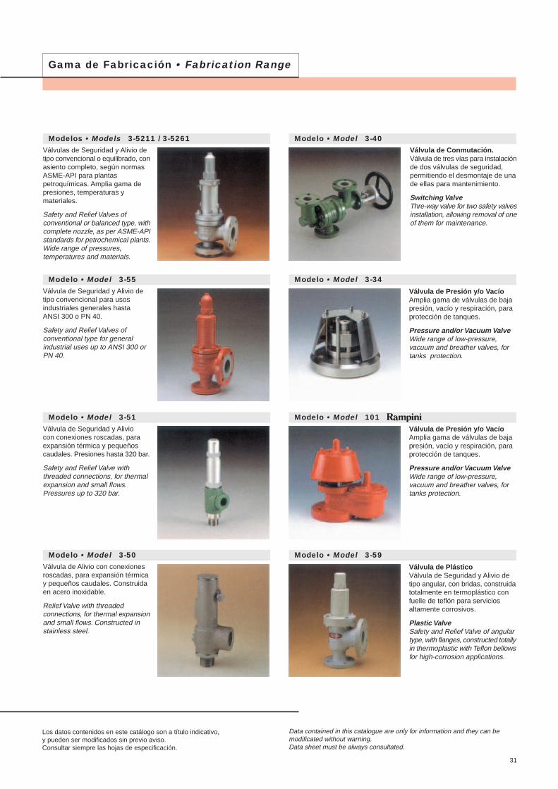
Los datos contenidos en este catálogo son a título indicativo,y pueden ser modificados sin previo aviso.Consultar siempre las hojas de especificación.
Data contained in this catalogue are only for information and they can bemodificated without warning.Data sheet must be always consultated.
Gama de Fabricación • Fabrication Range
Modelos • Models 3-5211 / 3-5261Válvulas de Seguridad y Alivio detipo convencional o equilibrado, conasiento completo, según normasASME-API para plantaspetroquímicas. Amplia gama depresiones, temperaturas ymateriales.
Safety and Relief Valves ofconventional or balanced type, withcomplete nozzle, as per ASME-APIstandards for petrochemical plants.Wide range of pressures,temperatures and materials.
Modelo • Model 3-55Válvula de Seguridad y Alivio detipo convencional para usosindustriales generales hastaANSI 300 o PN 40.
Safety and Relief Valves ofconventional type for generalindustrial uses up to ANSI 300 orPN 40.
Modelo • Model 3-51Válvula de Seguridad y Aliviocon conexiones roscadas, paraexpansión térmica y pequeñoscaudales. Presiones hasta 320 bar.
Safety and Relief Valve withthreaded connections, for thermalexpansion and small flows.Pressures up to 320 bar.
Modelo • Model 3-50Válvula de Alivio con conexionesroscadas, para expansión térmicay pequeños caudales. Construidaen acero inoxidable.
Relief Valve with threadedconnections, for thermal expansionand small flows. Constructed instainless steel.
Modelo • Model 3-40Válvula de Conmutación.Válvula de tres vías para instalaciónde dos válvulas de seguridad,permitiendo el desmontaje de unade ellas para mantenimiento.
Switching Valve Thre-way valve for two safety valvesinstallation, allowing removal of oneof them for maintenance.
Modelo • Model 3-34
Modelo • Model 101
Modelo • Model 3-59
Válvula de Presión y/o VacíoAmplia gama de válvulas de bajapresión, vacío y respiración, paraprotección de tanques.
Pressure and/or Vacuum Valve Wide range of low-pressure,vacuum and breather valves, fortanks protection.
Válvula de Presión y/o VacíoAmplia gama de válvulas de bajapresión, vacío y respiración, paraprotección de tanques.
Pressure and/or Vacuum Valve Wide range of low-pressure,vacuum and breather valves, fortanks protection.
Válvula de PlásticoVálvula de Seguridad y Alivio detipo angular, con bridas, construidatotalmente en termoplástico confuelle de teflón para serviciosaltamente corrosivos.
Plastic Valve Safety and Relief Valve of angulartype, with flanges, constructed totallyin thermoplastic with Teflon bellowsfor high-corrosion applications.
31