dorma bts65 - aceval · u formulario para fax u fuerza de cierre u funciones u imágenes u...
TRANSCRIPT
Dd
ü
ü
ü
ü
ü
BTS 65
DORMA
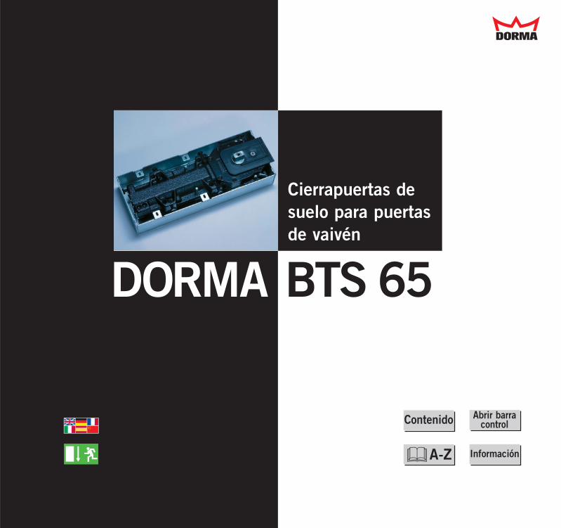
Cierrapuertas desuelo para puertasde vaivén
BTS 65DORMA
Dd
ü
ü
ü
ü
ü
Información
Abrir barracontrolContenido
&A-Z
DORMA BTS 65
ü
ü
ü
ü
ü
Info
&
El producto
Animación (vídeo)
Ejemplos de montaje
Técnica para el proyectista
Técnica para el instalador
Varios
Su socio a nivel mundial
Formulario para fax
U
U
U
U
U
U
U
U
Dd

DORMA BTS 65
ü
ü
ü
ü
ü
Info
&
U
U
U
U
Dd
Montaje en puertas completamente de cristal
Montaje en puertas demadera
Montaje en puertas demarcos tubulares de aluminio
Referencias de imágenes

Texto para especificación
Suministro y accesorios
Medidas de montaje
Folleto técnico
Certificado
Fórmula para la determina-ción de la fuerza de cierre
Otros cierrapuertas desuelo de DORMA
DORMA BTS 65
ü
ü
ü
ü
ü
Info
&
U
U
U
U
U
U
U
Dd
Instrucciones de montaje
Medidas de montaje
Folleto técnico
Folleto técnicoBTS Accesorios
Fórmula para la determina-ción de la fuerza de cierre
DORMA BTS 65
ü
ü
ü
ü
ü
Info
&
U
U
U
U
U
Dd
Otros cierrapuertas desuelo de DORMA
U
Folleto técnico
DORMA BTS 80
DORMA BTS 80 F, -EMB, -FLB
DORMA BTS 75 V
DORMA Cierrapuertas de suelo
U
U
U
Dd
ü
ü
ü
ü
ü
Info
&
W
DORMA BTS 65
U
U
Dd
ü
ü
ü
ü
ü
Info
&
Suministro y accesorios
Folleto técnicoBTS Accesorios
W
DORMA BTS 65
U
U
U
U
U
Dd
&
DORMA EPHerrajes de esquinas
DORMA UniversalHerrajes de esquinas
DORMA ARCOSHerrajes de esquinas
DORMA ARCOSRieles de puertasW
DORMA TPRieles de puertas
DORMA BTS 65
U
U
Dd
ü
ü
ü
ü
ü
Info
&
Instrucciones de montajeBTS 65
Instrucciones de montajePuertas completamente de cristal
W
DORMA BTS 65
U
U
Dd
ü
ü
ü
ü
ü
Info
&
Abreviaturas y símbolos
Clasificación según DIN EN 1154
W
U Abreviaciones
AccesoriosU Suministro y
accesoriosU Accesorios BTS
U Acerca del producto
U Animación
U AutoCAD (problemasal abrir DXF)
BrazoU Accesorios BTS
Caja empotradaU Folleto técnicoU Manual de montaje
U Cálculo de la prolon-gación del eje
U Certificados
Cierrapuertas de suelo U Otros cierrapuertas de
suelo de DORMA
U Clasificación segúnEN 1154
U Contenido
Dibujos CADU Ejemplos de montajeU Informaciones acerca
de los dibujos CAD
U Dimensiones
U Direcciones
DXF/DWG dibujosU Ejemplos de montaje
U Ejemplos de montaje
Ejes intercambiablesU Suministro y
accesoriosU Folleto técnico
U Ejes intercambiablesprolongados
U Fijación constante
U Fijación de apriete
U Folleto técnico
U Fórmula para el cálculode la fuerza de cierre
U Formulario para fax
U Fuerza de cierre
U Funciones
U Imágenes
U Informaciones acercadel CD
U Instalador, Técnicapara el
Instrucciones de montajeU BTS 65U Herrajes de esquinas
puertas de cristal
Manual de montajeU BTS 65U Herrajes de esquinas
puertas de cristal
Margen de ajuste en lacaja empotradaU Folleto técnicoU Manual de montaje
U Masa aislante
U Medidas de montaje
U Números de fax
U Números de pedido
U Números de teléfono
U Otros cierrapuertas desuelo de DORMA
U Peso BTS 65
U Peso de puerta
PivoteU Accesorios BTS
U Placa de recubrimiento
U Proyectista, Técnicapara el
Puertas completamentede cristalU Ejemplos de montaje
Puertas de maderaU Ejemplos de montaje
Puertas de marcos tubu-lares de aluminioU Ejemplos de montaje
U Referencias de imágenes
U Símbolos
U Socio a nivel mundial
U Specifiers, Technicaldata for
U Suministro
TécnicaU para el proyectistaU para el instalador
U Textos para especificación
U Velocidad de cierre
U Ventajas BTS 65
U Vídeo (animación)
U Zonas de cierre
Dd DORMA BTS 65 Índice
A
EM
N
O
P
R
S
T
I
B
C
D
V
Z
F
Contenido
Dd
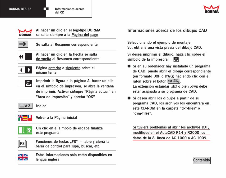
Informaciones acerca de los dibujos CAD
DORMA BTS 65 Informaciones acercadel CD
Seleccionando el ejemplo de montaje, Vd. obtiene una vista previa del dibujo CAD.
Si desea imprimir el dibujo, haga clic sobre elsímbolo de la impresora
3 Si en su ordenador hay instalado un programade CAD, puede abrir el dibujo correspondiente(en formato DXF o DWG) haciendo clic con elratón sobre el botón .La extensión estándar .dxf o bien .dwg debeestar asignada a su programa de CAD.
3 Si desea abrir los dibujos a partir de suprograma CAD, los archivos los encontrará eneste CD-ROM en la carpeta ”dxf-files” o ”dwg-files”.
ZPágina anterior o siguiente sobre elmismo tema
Imprimir la figura o la página: Al hacer un clicen el símbolo de impresora, se abre la ventanade imprimir. Activar siempre ”Página actual” en”Área de impresión” y apretar ”OK”
Se salta al Resumen correspondiente
Al hacer un clic en la flecha se salta de vuelta al Resumen correspondiente
Un clic en el símbolo de escape finalizaeste programa
Volver a la Página inicial
Al hacer un clic en el logotipo DORMAse salta siempre a la Página del page
InfoU
•
Dd
Z
E
W
Si tuviera problemas al abrir los archivos DXF,modifique en el AutoCAD R14 y R2000 losdatos de la 8. línea de AC 1000 a AC 1009.
dxf öffnen opening
ü
ü
ü
ü
ü
& Índice
F8 Funciones de teclas „F8“ – abre y cierra labarra de control para lupa, buscar, etc.
Estas informaciones sólo están disponibles enlengua inglesa Contenido
DORMA BTS 65Cierrapuertas de suelo
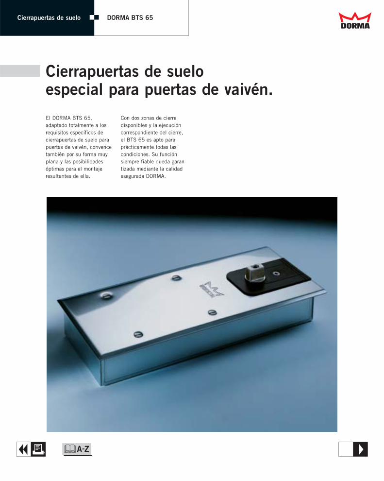
Cierrapuertas de suelo especial para puertas de vaivén.
El DORMA BTS 65, adaptado totalmente a losrequisitos específicos decierrapuertas de suelo parapuertas de vaivén, convencetambién por su forma muyplana y las posibilidadesóptimas para el montajeresultantes de ella.
Con dos zonas de cierredisponibles y la ejecucióncorrespondiente del cierre,el BTS 65 es apto paraprácticamente todas las condiciones. Su funciónsiempre fiable queda garan-tizada mediante la calidadasegurada DORMA.
A T&
Dd

DORMA BTS 65
– máx. 100 kg de peso de la puerta– fuerza de cierre a opción entre EN 3 o EN 4– velocidad de cierre ajustable de modo continuo
en la zona de 130 a 0° (1)– segunda zona de cierre ajustable
130 a 20º (2)– fijación constante para 90° (opcional) (3)– tope de puerta OGRO TZ 5000 (4)
20°
130°
90°
1
23
20°
130°
90°
1
23
4
4
108 276
40
130
290
Ejes intercambiables prolongadosLos ejes intercambiables seutilizan para aumentar, encaso necesario, la holgurade suelo.Se suministran en longitudesde 5 a 50 mm.
Placa de recubrimientoOpción entre acero inoxidable o latón pulido mate.
Datos y características BTS 65
Fuerza de cierre EN 3 EN 4Puertas generales1) ≤ 950 mm 2 –y puertas exteriores1) 2) ≤ 1150 mm – 2
Peso máx. de puerta en kg 100 100
Velocidad de cierre ajustablede modo continuo mediante válvulas 2 2
Fijación constante 90° " "
Cierrapuertas homologado según EN 1154 2 2
2 sí – no " opción
1) Para puertas de altura y peso especial, así como para aquellas que secierran permanentemente con fuerte presión de viento, recomendamosel cierrapuertas de suelo con el siguiente momento de cierre más alto o el DORMA BTS 80.
2) Ángulo de apertura máx. 130°. Para puertas que pueden abrirse más de 130° es necesario un tope depuerta (p. ej. OGRO TZ 5000).
A R&
Dd

DORMA BTS 65 Textos para especificación
Textos para especificación DORMA BTS 65
b BTS65 DORMA BTS 65, tamaño EN 3Cierrapuertas de suelo según EN 1154, para puertas de vaivén de hasta 100 kg de peso.Con proceso hidráulico de cierre totalmente controlado a partir de aprox. 130°. Incluye caja empotrada, eje intercambiable y placa de recubrimiento.Altura total de la caja empotrada: 40 mmEjecución de la placa de recubrimiento:( ) Acero inoxidable ( ) Latón pulido mate
DORMA BTS 65, tamaño EN 3, fijación 90°Cierrapuertas de suelo según EN 1154, para puertas de vaivén de hasta 100 kg de peso.Con proceso hidráulico de cierre totalmente controlado a partir de aprox. 130°. Incluye caja empotrada, eje intercambiable y placa de recubrimiento.Altura total de la caja empotrada: 40 mmEjecución de la placa de recubrimiento:( ) Acero inoxidable ( ) Latón pulido mate
DORMA BTS 65, tamaño EN 4Cierrapuertas de suelo según EN 1154, para puertas de vaivén de hasta 100 kg de peso.Con proceso hidráulico de cierre totalmente controlado a partir de aprox. 130°. Incluye caja empotrada, eje intercambiable y placa de recubrimiento.Altura total de la caja empotrada: 40 mmEjecución de la placa de recubrimiento:( ) Acero inoxidable ( ) Latón pulido mate
DORMA BTS 65, tamaño EN 4, fijación 90°Cierrapuertas de suelo según EN 1154, para puertas de vaivén de hasta 100 kg de peso.Con proceso hidráulico de cierre totalmente controlado a partir de aprox. 130°. Incluye caja empotrada, eje intercambiable y placa de recubrimiento.Altura total de la caja empotrada: 40 mmEjecución de la placa de recubrimiento:( ) Acero inoxidable ( ) Latón pulido mate
Dd
A & openWord file
Cierrapuertas de suelo
BTS65DORMA
T
&
W
Dd

DORMA BTS 65 Cierrapuertas de suelo
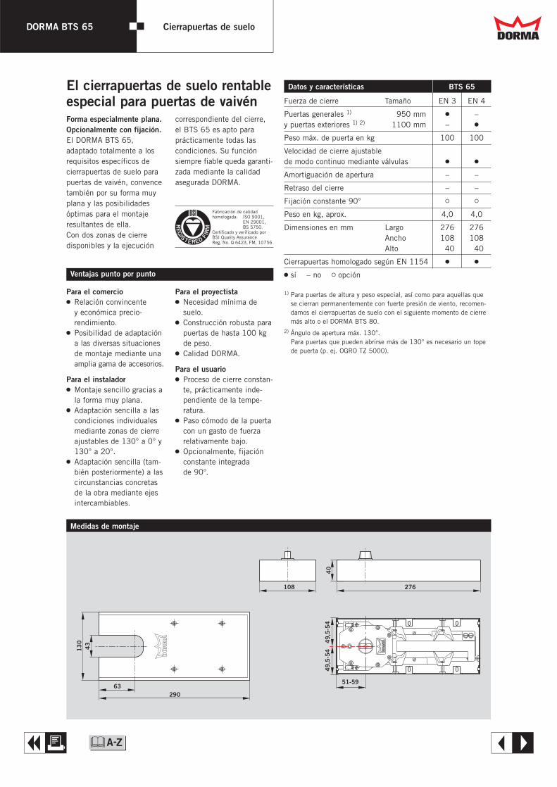
Fuerza de cierre Tamaño EN 3 EN 4
Puertas generales 1) ≤ 1950 mm 2 –y puertas exteriores 1) 2) ≤ 1100 mm – 2
Peso máx. de puerta en kg 100 100
Velocidad de cierre ajustablede modo continuo mediante válvulas 2 2
Amortiguación de apertura – –
Retraso del cierre – –
Fijación constante 90° " "
Peso en kg, aprox. 4,0 4,0
Dimensiones en mm Largo 276 276Ancho 108 108Alto 040 040
Cierrapuertas homologado según EN 1154 2 2
2 sí – no " opción
1) Para puertas de altura y peso especial, así como para aquellas quese cierran permanentemente con fuerte presión de viento, recomen-damos el cierrapuertas de suelo con el siguiente momento de cierremás alto o el DORMA BTS 80.
2) Ángulo de apertura máx. 130°. Para puertas que pueden abrirse más de 130° es necesario un topede puerta (p. ej. OGRO TZ 5000).
Datos y características BTS 65El cierrapuertas de suelo rentableespecial para puertas de vaivén
Para el comercio2 Relación convincente
y económica precio-rendimiento.
2 Posibilidad de adaptacióna las diversas situacionesde montaje mediante unaamplia gama de accesorios.
Para el instalador2 Montaje sencillo gracias a
la forma muy plana.2 Adaptación sencilla a las
condiciones individualesmediante zonas de cierreajustables de 130° a 0° y130° a 20°.
2 Adaptación sencilla (tam-bién posteriormente) a lascircunstancias concretasde la obra mediante ejesintercambiables.
Para el proyectista2 Necesidad mínima de
suelo.2 Construcción robusta para
puertas de hasta 100 kgde peso.
2 Calidad DORMA.
Para el usuario2 Proceso de cierre constan-
te, prácticamente inde-pendiente de la tempe-ratura.
2 Paso cómodo de la puertacon un gasto de fuerzarelativamente bajo.
2 Opcionalmente, fijaciónconstante integrada de 90°.
Ventajas punto por punto
Forma especialmente plana.Opcionalmente con fijación.El DORMA BTS 65, adaptado totalmente a losrequisitos específicos decierrapuertas de suelo parapuertas de vaivén, convencetambién por su forma muyplana y las posibilidadesóptimas para el montajeresultantes de ella. Con dos zonas de cierre disponibles y la ejecución
correspondiente del cierre,el BTS 65 es apto paraprácticamente todas las condiciones. Su funciónsiempre fiable queda garanti-zada mediante la calidadasegurada DORMA.
Fabricación de calidad homologada: ISO 9001, EN 29001, BS 5750.Certificado y verificado porBSI Quality AssuranceReg. No. Q 6423, FM, 10756
A E
Dd
&
108 276
40
43
13
0
63290
51-59
49,
5-5
44
9,5
-54
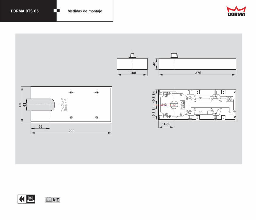
Medidas de montaje

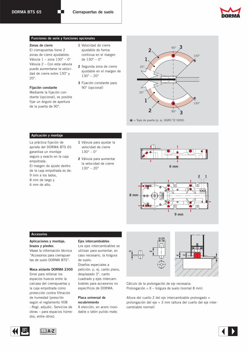
Zonas de cierreEl cierrapuertas tiene 2zonas de cierre ajustables:Válvula 1 – zona 130° – 0°Válvula 2 – Con esta válvulapuede aumentarse la veloci-dad de cierre entre 130° y20°.
Fijación constanteMediante la fijación con-stante (opcional), es posiblefijar un ángulo de aperturade la puerta de 90°.
X Z
8
3
25
Z
Cálculo de la prolongación de eje necesaria:Prolongación = X – holgura de suelo (normal 8 mm)
Altura del cuello Z del eje intercambiable prolongado = prolongación del eje + 3 mm (altura del cuello del eje inter-cambiable normal)
Funciones de serie y funciones opcionales
Aplicaciones y montaje, brazos y pivotesVéase la información técnica“Accesorios para cierrapuer-tas de suelo DORMA BTS”.
Masa aislante DORMA 2300Sirve para rellenar losespacios huecos entre lacarcasa del cierrapuertas yla caja empotrada comoprotección contra filtraciónde humedad (prescritosegún el reglamento VOB–Regl. adjudic. Servicios deobras – para espacios húme-dos, entre otros).
Ejes intercambiablesLos ejes intercambiables seutilizan para aumentar, encaso necesario, la holgurade suelo.Diseños especiales a petición: p. ej. canto plano,desplazado 3°, cantocuadrado y ejes intercam-biables para accesorios noespecíficos de DORMA.
Placa universal derecubrimientoA elección, en acero inoxi-dable o latón pulido mate.
Accesorios
DORMA BTS 65 Cierrapuertas de suelo
1 Velocidad de cierre ajustable de forma continua en el margen de 130° – 0°
2 Segunda zona de cierreajustable en el margen de130° – 20°
3 Fijación constante para90° (opcional)
La práctica fijación de apriete del DORMA BTS 65garantiza un montaje seguro y exacto en la cajaempotrada. El margen de ajuste dentrode la caja empotrada es de:9 mm a los lados, 8 mm de largo y 6 mm de alto.
Aplicación y montaje
1 Válvula para ajustar la velocidad de cierre 130° – 0°
2 Válvula para aumentar la velocidad de cierre130° – 20°
A E
Dd
&
20°
130°
90°
1
23
20°
130°
90°
1
2 3= Tope de puerta (p. ej. OGRO TZ 5000)
6 mm
9 mm
8 mm
2 1

DORMA BTS 65 Cierrapuertas de suelo
WN
05
22
61
51
53
2,
04
/03
, B
TS 6
5,
E,
x. D
P/C
tP,
04
/03
S
ujet
o a
mod
ific
acio
nes
sin
prev
io a
viso
.
Texto para especificación
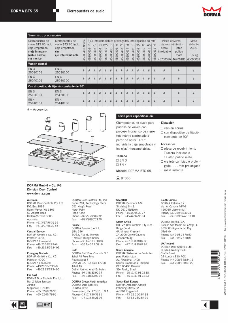
Cierrapuertas de suelo parapuertas de vaivén con proceso hidráulico de cierretotalmente controlado a partir de aprox. 130°, incluida la caja empotrada ylos ejes intercambiables.
TamañoY EN 3Y EN 4
Modelo: DORMA BTS 65
b BTS65
Ejecución
Y versión normalY con dispositivo de fijación
constante de 90°
AccesoriosY placa de recubrimiento
Y acero inoxidableY latón pulido mate
Y eje intercambiable prolon-gado, . . . mm prolongado
Y masa aislante
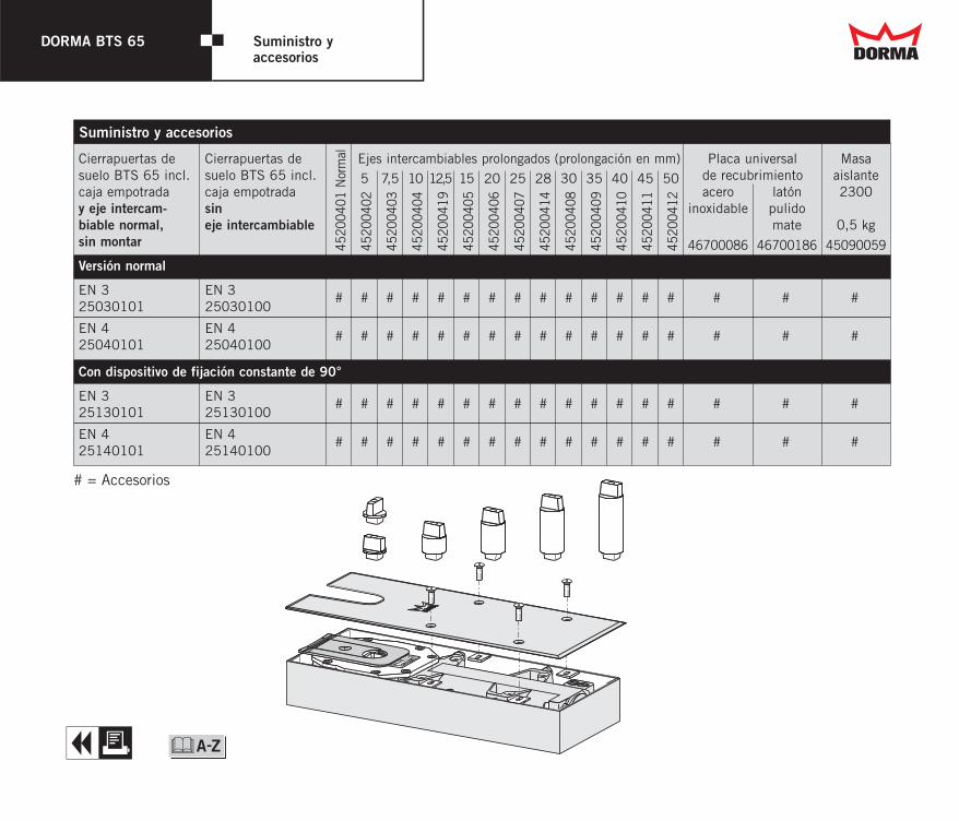
Cierrapuertas de Cierrapuertas de Ejes intercambiables prolongados (prolongación en mm) Placa universal Masasuelo BTS 65 incl. suelo BTS 65 incl. 5 7,5 10 12,5 15 20 25 28 30 35 40 45 50 de recubrimiento aislantecaja empotrada caja empotrada acero latón 2300y eje intercam- sin inoxidable pulidobiable normal, eje intercambiable mate 0,5 kgsin montar 46700086 46700186 45090059
Versión normal
EN 3 EN 325030101 25030100
# # # # # # # # # # # # # # # # #
EN 4 EN 425040101 25040100
# # # # # # # # # # # # # # # # #
Con dispositivo de fijación constante de 90°
EN 3 EN 325130101 25130100
# # # # # # # # # # # # # # # # #
EN 4 EN 425140101 25140100
# # # # # # # # # # # # # # # # #
4520
0401
Nor
mal
4520
0402
4520
0403
4520
0404
4520
0419
4520
0405
4520
0406
4520
0407
4520
0414
4520
0408
4520
0409
4520
0410
4520
0411
4520
0412
# = Accesorios
AustraliaDORMA Door Controls Pty. Ltd.P.O. Box 1092Narre Warren Vic 380552 Abbott RoadHallam/Victoria 3803AustraliaPhone: +61 3/97 96 35 55Fax: +61 3/97 96 39 55
Central EuropeDORMA GmbH + Co. KGPostfach 40 09D-58247 EnnepetalPhone: +49 2333/793-0Fax: +49 2333/793495
Emerging MarketsDORMA GmbH + Co. KGPostfach 40 09D-58247 EnnepetalPhone: +49 23 33/7 93-0Fax: +49 23 33/793495
Far EastDORMA Door Controls Pte. Ltd.No. 2 Jalan TerusanJurongSingapore 619285Phone: +65 6268/7633Fax: +65 6265/7995
DORMA Door Controls Pte. Ltd.Room 701, Technology Plaza651 King’s RoadNorth PointHong KongPhone: +825/250 346 32Fax: +825/288 753 70
FranceDORMA France S.A.R.L.Silic 53630/32, Rue du MorvanF-94633 Rungis-CedexPhone: +33 1/45 12 08 08Fax: +33 1/45 12 08 18
GulfDORMA Gulf Door Controls FZEJebel Ali Free ZoneRoundabout 8Unit VC 02, P.O. Box 17268Jebel AliDubai, United Arab EmiratesPhone: +971 48/83 90 14Fax: +971 48/83 90 15
DORMA Group North AmericaDORMA Door ControlsDORMA Drive Reamstown, Pa. 17567, U.S.A.Phone: +1717/3 36 38 81Fax: +1717/3 36 21 06
ScanBaltDORMA Danmark A/SSindalvej 6 – 8DK-2610 RødovrePhone: +45 44/94 30 77Fax: +45 44/94 95 04
South AfricaDORMA Door Controls (Pty.) Ltd.Kings Court4A Mineral CrescentZA-2000 Crown/GautengJohannesburgPhone: +27 11/8 30 02 80Fax: +27 11/8 30 02 91
South AmericaDORMA Sistemas de Controlespara Portas Ltda.Av. Piracema, 1400Centro Empresarial TamboreCEP 06400 Barueri/São Paulo, BrasilPhone: +55 11/41 91 22 38Fax: +55 11/41 91 22 83
South-East EuropeDORMA AUSTRIA GmbHPebering Strass 22A-5301 EugendorfPhone: +43 62 25/2 84 88Fax: +43 62 25/2 84 91
South EuropeDORMA Italiana S.r.l.Via. A. Canova 44/46I-20035 Lissone (MI)Phone: +39 039/24 40 31Fax: +39 039/24 40 33 10
DORMA Ibérica, S.A.Camino San Martín de la Vega, 4E-28500 Arganda del Rey(Madrid)Phone: +34 91/8 75 78 50Fax: +34 91/8 75 78 81
UK/IrelandDORMA Door Controls Ltd.DORMA Trading ParkStaffa RoadGB-London E10 7QXPhone: +44 208/5 58 84 11Fax: +44 208/5 58 61 22
DORMA GmbH + Co. KGDivision Door Controlwww.dorma.com
Suministro y accesorios
A R
Dd
&

Cierrapuertas de suelo
BTS65DORMA
T
&
W
Dd
DORMA BTS 65 Cierrapuertas de suelo
Fuerza de cierre Tamaño EN 3 EN 4
Puertas generales 1) ≤ 1950 mm 2 –y puertas exteriores 1) 2) ≤ 1100 mm – 2
Peso máx. de puerta en kg 100 100
Velocidad de cierre ajustablede modo continuo mediante válvulas 2 2
Amortiguación de apertura – –
Retraso del cierre – –
Fijación constante 90° " "
Peso en kg, aprox. 4,0 4,0
Dimensiones en mm Largo 276 276Ancho 108 108Alto 040 040
Cierrapuertas homologado según EN 1154 2 2
2 sí – no " opción
1) Para puertas de altura y peso especial, así como para aquellas quese cierran permanentemente con fuerte presión de viento, recomen-damos el cierrapuertas de suelo con el siguiente momento de cierremás alto o el DORMA BTS 80.
2) Ángulo de apertura máx. 130°. Para puertas que pueden abrirse más de 130° es necesario un topede puerta (p. ej. OGRO TZ 5000).
Datos y características BTS 65El cierrapuertas de suelo rentableespecial para puertas de vaivén
Para el comercio2 Relación convincente
y económica precio-rendimiento.
2 Posibilidad de adaptacióna las diversas situacionesde montaje mediante unaamplia gama de accesorios.
Para el instalador2 Montaje sencillo gracias a
la forma muy plana.2 Adaptación sencilla a las
condiciones individualesmediante zonas de cierreajustables de 130° a 0° y130° a 20°.
2 Adaptación sencilla (tam-bién posteriormente) a lascircunstancias concretasde la obra mediante ejesintercambiables.
Para el proyectista2 Necesidad mínima de
suelo.2 Construcción robusta para
puertas de hasta 100 kgde peso.
2 Calidad DORMA.
Para el usuario2 Proceso de cierre constan-
te, prácticamente inde-pendiente de la tempe-ratura.
2 Paso cómodo de la puertacon un gasto de fuerzarelativamente bajo.
2 Opcionalmente, fijaciónconstante integrada de 90°.
Ventajas punto por punto
Forma especialmente plana.Opcionalmente con fijación.El DORMA BTS 65, adaptado totalmente a losrequisitos específicos decierrapuertas de suelo parapuertas de vaivén, convencetambién por su forma muyplana y las posibilidadesóptimas para el montajeresultantes de ella. Con dos zonas de cierre disponibles y la ejecución
correspondiente del cierre,el BTS 65 es apto paraprácticamente todas las condiciones. Su funciónsiempre fiable queda garanti-zada mediante la calidadasegurada DORMA.
Fabricación de calidad homologada: ISO 9001, EN 29001, BS 5750.Certificado y verificado porBSI Quality AssuranceReg. No. Q 6423, FM, 10756
A E
Dd
&
108 276
40
43
13
0
63290
51-59
49,
5-5
44
9,5
-54
Medidas de montaje
Zonas de cierreEl cierrapuertas tiene 2zonas de cierre ajustables:Válvula 1 – zona 130° – 0°Válvula 2 – Con esta válvulapuede aumentarse la veloci-dad de cierre entre 130° y20°.
Fijación constanteMediante la fijación con-stante (opcional), es posiblefijar un ángulo de aperturade la puerta de 90°.
X Z
8
3
25
Z
Cálculo de la prolongación de eje necesaria:Prolongación = X – holgura de suelo (normal 8 mm)
Altura del cuello Z del eje intercambiable prolongado = prolongación del eje + 3 mm (altura del cuello del eje inter-cambiable normal)
Funciones de serie y funciones opcionales
Aplicaciones y montaje, brazos y pivotesVéase la información técnica“Accesorios para cierrapuer-tas de suelo DORMA BTS”.
Masa aislante DORMA 2300Sirve para rellenar losespacios huecos entre lacarcasa del cierrapuertas yla caja empotrada comoprotección contra filtraciónde humedad (prescritosegún el reglamento VOB–Regl. adjudic. Servicios deobras – para espacios húme-dos, entre otros).
Ejes intercambiablesLos ejes intercambiables seutilizan para aumentar, encaso necesario, la holgurade suelo.Diseños especiales a petición: p. ej. canto plano,desplazado 3°, cantocuadrado y ejes intercam-biables para accesorios noespecíficos de DORMA.
Placa universal derecubrimientoA elección, en acero inoxi-dable o latón pulido mate.
Accesorios
DORMA BTS 65 Cierrapuertas de suelo
1 Velocidad de cierre ajustable de forma continua en el margen de 130° – 0°
2 Segunda zona de cierreajustable en el margen de130° – 20°
3 Fijación constante para90° (opcional)
La práctica fijación de apriete del DORMA BTS 65garantiza un montaje seguro y exacto en la cajaempotrada. El margen de ajuste dentrode la caja empotrada es de:9 mm a los lados, 8 mm de largo y 6 mm de alto.
Aplicación y montaje
1 Válvula para ajustar la velocidad de cierre 130° – 0°
2 Válvula para aumentar la velocidad de cierre130° – 20°
A E
Dd
&
20°
130°
90°
1
23
20°
130°
90°
1
2 3= Tope de puerta (p. ej. OGRO TZ 5000)
6 mm
9 mm
8 mm
2 1
DORMA BTS 65 Cierrapuertas de suelo
WN
05
22
61
51
53
2,
04
/03
, B
TS 6
5,
E,
x. D
P/C
tP,
04
/03
S
ujet
o a
mod
ific
acio
nes
sin
prev
io a
viso
.
Texto para especificación
Cierrapuertas de suelo parapuertas de vaivén con proceso hidráulico de cierretotalmente controlado a partir de aprox. 130°, incluida la caja empotrada ylos ejes intercambiables.
TamañoY EN 3Y EN 4
Modelo: DORMA BTS 65
b BTS65
Ejecución
Y versión normalY con dispositivo de fijación
constante de 90°
AccesoriosY placa de recubrimiento
Y acero inoxidableY latón pulido mate
Y eje intercambiable prolon-gado, . . . mm prolongado
Y masa aislante
Cierrapuertas de Cierrapuertas de Ejes intercambiables prolongados (prolongación en mm) Placa universal Masasuelo BTS 65 incl. suelo BTS 65 incl. 5 7,5 10 12,5 15 20 25 28 30 35 40 45 50 de recubrimiento aislantecaja empotrada caja empotrada acero latón 2300y eje intercam- sin inoxidable pulidobiable normal, eje intercambiable mate 0,5 kgsin montar 46700086 46700186 45090059
Versión normal
EN 3 EN 325030101 25030100
# # # # # # # # # # # # # # # # #
EN 4 EN 425040101 25040100
# # # # # # # # # # # # # # # # #
Con dispositivo de fijación constante de 90°
EN 3 EN 325130101 25130100
# # # # # # # # # # # # # # # # #
EN 4 EN 425140101 25140100
# # # # # # # # # # # # # # # # #
4520
0401
Nor
mal
4520
0402
4520
0403
4520
0404
4520
0419
4520
0405
4520
0406
4520
0407
4520
0414
4520
0408
4520
0409
4520
0410
4520
0411
4520
0412
# = Accesorios
AustraliaDORMA Door Controls Pty. Ltd.P.O. Box 1092Narre Warren Vic 380552 Abbott RoadHallam/Victoria 3803AustraliaPhone: +61 3/97 96 35 55Fax: +61 3/97 96 39 55
Central EuropeDORMA GmbH + Co. KGPostfach 40 09D-58247 EnnepetalPhone: +49 2333/793-0Fax: +49 2333/793495
Emerging MarketsDORMA GmbH + Co. KGPostfach 40 09D-58247 EnnepetalPhone: +49 23 33/7 93-0Fax: +49 23 33/793495
Far EastDORMA Door Controls Pte. Ltd.No. 2 Jalan TerusanJurongSingapore 619285Phone: +65 6268/7633Fax: +65 6265/7995
DORMA Door Controls Pte. Ltd.Room 701, Technology Plaza651 King’s RoadNorth PointHong KongPhone: +825/250 346 32Fax: +825/288 753 70
FranceDORMA France S.A.R.L.Silic 53630/32, Rue du MorvanF-94633 Rungis-CedexPhone: +33 1/45 12 08 08Fax: +33 1/45 12 08 18
GulfDORMA Gulf Door Controls FZEJebel Ali Free ZoneRoundabout 8Unit VC 02, P.O. Box 17268Jebel AliDubai, United Arab EmiratesPhone: +971 48/83 90 14Fax: +971 48/83 90 15
DORMA Group North AmericaDORMA Door ControlsDORMA Drive Reamstown, Pa. 17567, U.S.A.Phone: +1717/3 36 38 81Fax: +1717/3 36 21 06
ScanBaltDORMA Danmark A/SSindalvej 6 – 8DK-2610 RødovrePhone: +45 44/94 30 77Fax: +45 44/94 95 04
South AfricaDORMA Door Controls (Pty.) Ltd.Kings Court4A Mineral CrescentZA-2000 Crown/GautengJohannesburgPhone: +27 11/8 30 02 80Fax: +27 11/8 30 02 91
South AmericaDORMA Sistemas de Controlespara Portas Ltda.Av. Piracema, 1400Centro Empresarial TamboreCEP 06400 Barueri/São Paulo, BrasilPhone: +55 11/41 91 22 38Fax: +55 11/41 91 22 83
South-East EuropeDORMA AUSTRIA GmbHPebering Strass 22A-5301 EugendorfPhone: +43 62 25/2 84 88Fax: +43 62 25/2 84 91
South EuropeDORMA Italiana S.r.l.Via. A. Canova 44/46I-20035 Lissone (MI)Phone: +39 039/24 40 31Fax: +39 039/24 40 33 10
DORMA Ibérica, S.A.Camino San Martín de la Vega, 4E-28500 Arganda del Rey(Madrid)Phone: +34 91/8 75 78 50Fax: +34 91/8 75 78 81
UK/IrelandDORMA Door Controls Ltd.DORMA Trading ParkStaffa RoadGB-London E10 7QXPhone: +44 208/5 58 84 11Fax: +44 208/5 58 61 22
DORMA GmbH + Co. KGDivision Door Controlwww.dorma.com
Suministro y accesorios
A R
Dd
&
Dd DORMA BTS 65 Suministro y accesorios
Cierrapuertas de Cierrapuertas de Ejes intercambiables prolongados (prolongación en mm) Placa universal Masasuelo BTS 65 incl. suelo BTS 65 incl. 5 7,5 10 12,5 15 20 25 28 30 35 40 45 50 de recubrimiento aislantecaja empotrada caja empotrada acero latón 2300y eje intercam- sin inoxidable pulidobiable normal, eje intercambiable mate 0,5 kgsin montar 46700086 46700186 45090059
Versión normal
EN 3 EN 325030101 25030100
# # # # # # # # # # # # # # # # #
EN 4 EN 425040101 25040100
# # # # # # # # # # # # # # # # #
Con dispositivo de fijación constante de 90°
EN 3 EN 325130101 25130100
# # # # # # # # # # # # # # # # #
EN 4 EN 425140101 25140100
# # # # # # # # # # # # # # # # #
4520
0401
Nor
mal
4520
0402
4520
0403
4520
0404
4520
0419
4520
0405
4520
0406
4520
0407
4520
0414
4520
0408
4520
0409
4520
0410
4520
0411
4520
0412
# = Accesorios
Suministro y accesorios
A &
Dd DORMA BTS 65 Medidas de montaje
A &
108 276
40
43
13
0
63290
51-59
49,
5-5
44
9,5
-54

Dd DORMA BTS 65 Medidas de montaje
A &
108 276
40
43
13
0
63290
51-59
49,
5-5
44
9,5
-54
WN
05
60
58
03
/03
a b/ /
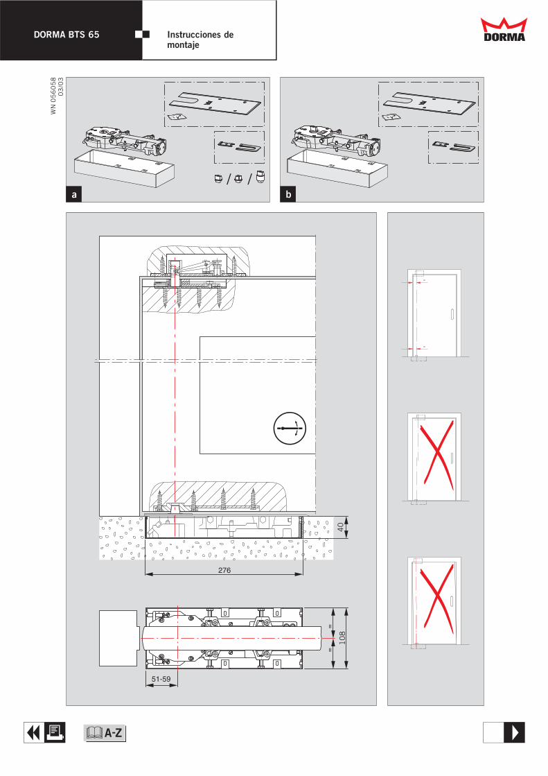
=
=
276
40
51-59
==
10
8
Dd
A T
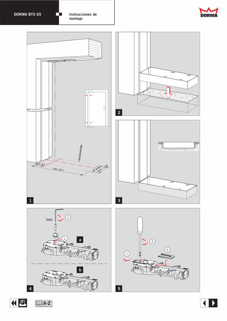
DORMA BTS 65 Instrucciones de montaje
&
4 5
1
2
3
SW5
min
. 109=
=min. 277
min. 51
=
=
1.
1.
2.
2.
3.a
b
Dd
A E
DORMA BTS 65 Instrucciones de montaje
&
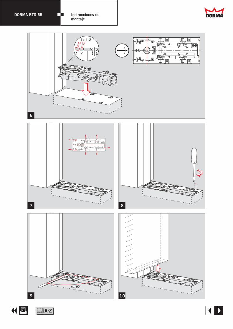
10
6
7 8
9
1 2
1 / 1+2
ca. 90o
Dd
A E
DORMA BTS 65 Instrucciones de montaje
&
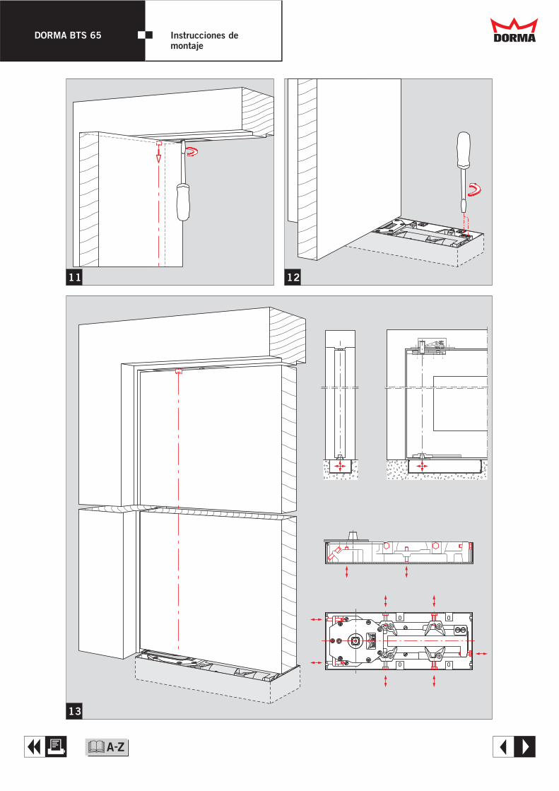
11 12
13
Dd
A E
DORMA BTS 65 Instrucciones de montaje
&
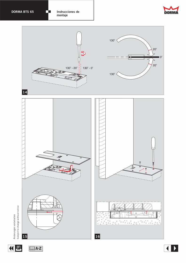
14
15 16
Subje
ctto
chan
gew
ithou
tnot
ice
Änder
unge
nvo
rbeh
alte
n
130 - 20o o
130 - 0o o
0o
20o
20o
130o
130o
Dd
A E
DORMA BTS 65 Instrucciones de montaje
&
WN
05
60
59
02
/03
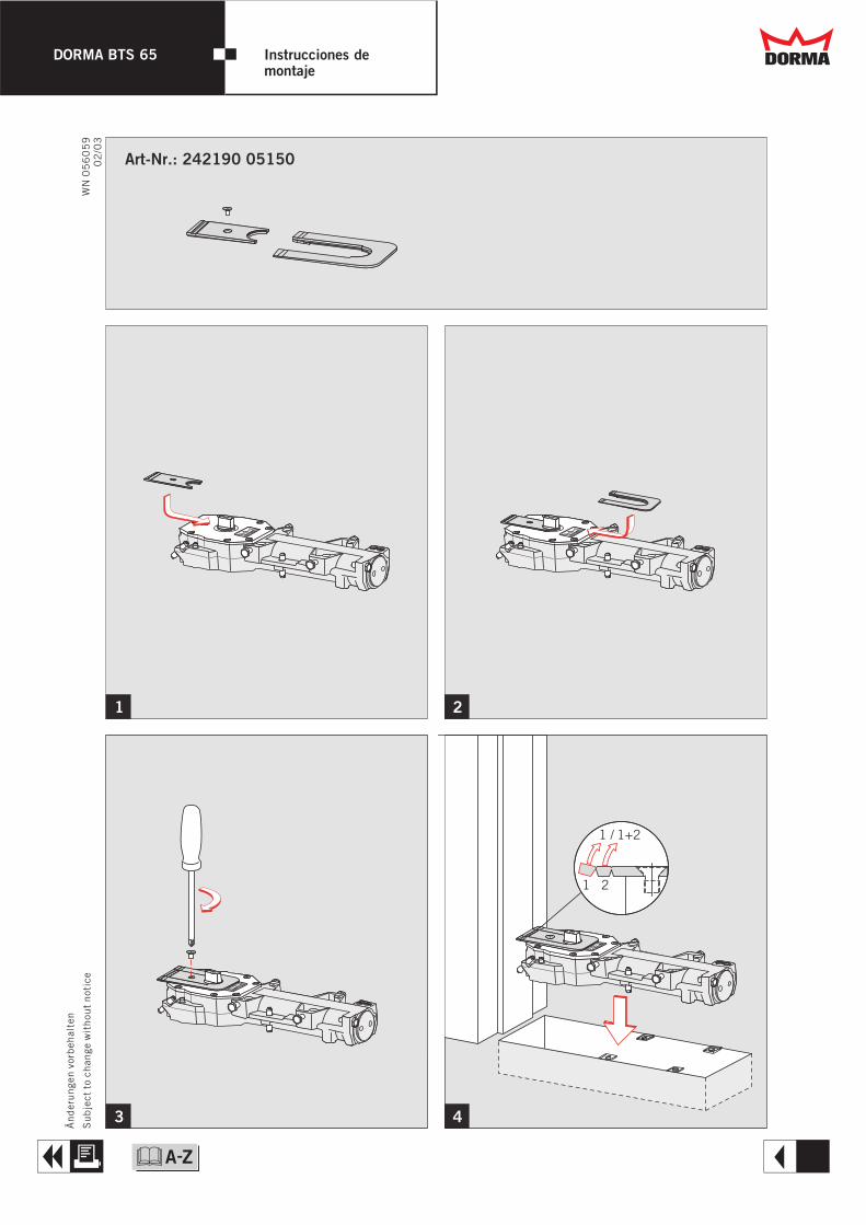
1 2
3 4
Subje
ctto
chan
gew
ithou
tnot
ice
Änder
unge
nvo
rbeh
alte
n
1 2
1 / 1+2
Art-Nr.: 242190 05150
Dd
A R
DORMA BTS 65 Instrucciones de montaje
&
DORMA BTS 65 Toughened GlassDoors Dd
T
Q
dwg opening
dxf opening
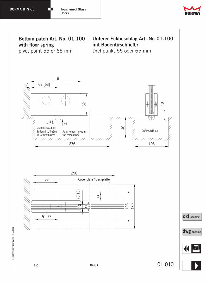
Unterer Eckbeschlag Art.-Nr. 01.100 mit Bodentürschließer Drehpunkt 55 oder 65 mm
Bottom patch Art. No. 01.100 with floor spring pivot point 55 or 65 mm
DORMA BTS 65 Toughened GlassDoors Dd
E
Q
dwg opening
dxf opening
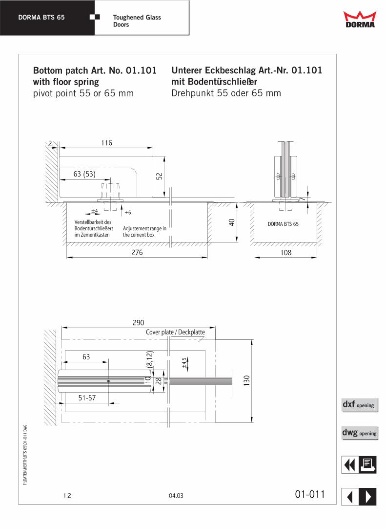
Unterer Eckbeschlag Art.-Nr. 01.101 mit Bodentürschließer Drehpunkt 55 oder 65 mm
Bottom patch Art. No. 01.101 with floor spring pivot point 55 or 65 mm
DORMA BTS 65 Toughened GlassDoors Dd
R
Q
dwg opening
dxf opening
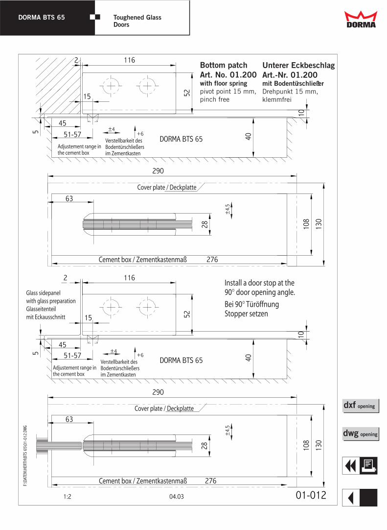
Unterer Eckbeschlag Art.-Nr. 01.200 mit Bodentürschließer Drehpunkt 15 mm, klemmfrei
Bottom patch Art. No. 01.200 with floor spring pivot point 15 mm, pinch free
DORMA BTS 65 Toughened GlassDoors Dd
Q
dwg opening
dxf opening
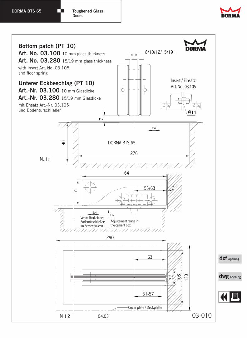
DdBottom patch (PT 10) Art. No. 03.100 10 mm glass thickness Art. No. 03.280 15/19 mm glass thickness
with insert Art. No. 03.105 and floor spring
Unterer Eckbeschlag (PT 10) Art.-Nr. 03.100 10 mm Glasdicke
Art.-Nr. 03.280 15/19 mm Glasdicke
mit Ensatz Art.-Nr. 03.105 und Bodentürschließer
DORMA BTS 65 Toughened GlassDoors Dd
T
Q
dwg opening
dxf opening
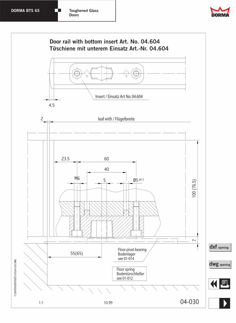
Door rail with bottom insert Art. No. 04.604Türschiene mit unterem Einsatz Art.-Nr. 04.604

DORMA BTS 65 Toughened GlassDoors Dd
R
Q
dwg opening
dxf opening
Door rail with bottom strap in torged steel Türschiene mit unterem StahltürhebelArt.-Nr. 8.04.048.001.50
DORMA BTS 65 Toughened GlassDoors Dd
Q
dwg opening
dxf opening
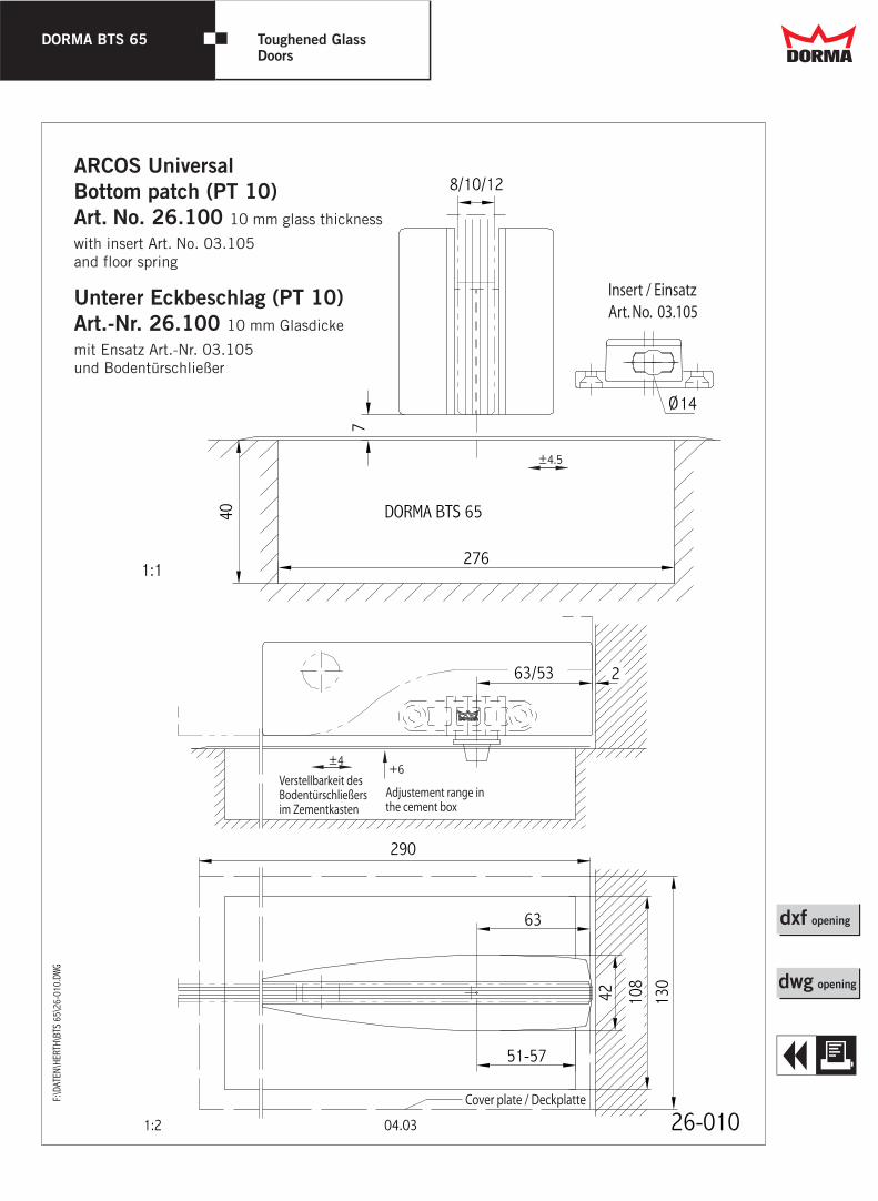
ARCOS UniversalBottom patch (PT 10) Art. No. 26.100 10 mm glass thickness
with insert Art. No. 03.105 and floor spring
Unterer Eckbeschlag (PT 10) Art.-Nr. 26.100 10 mm Glasdicke
mit Ensatz Art.-Nr. 03.105 und Bodentürschließer
DORMA BTS 65 Toughened GlassDoors Dd
T
Q
dwg opening
dxf opening
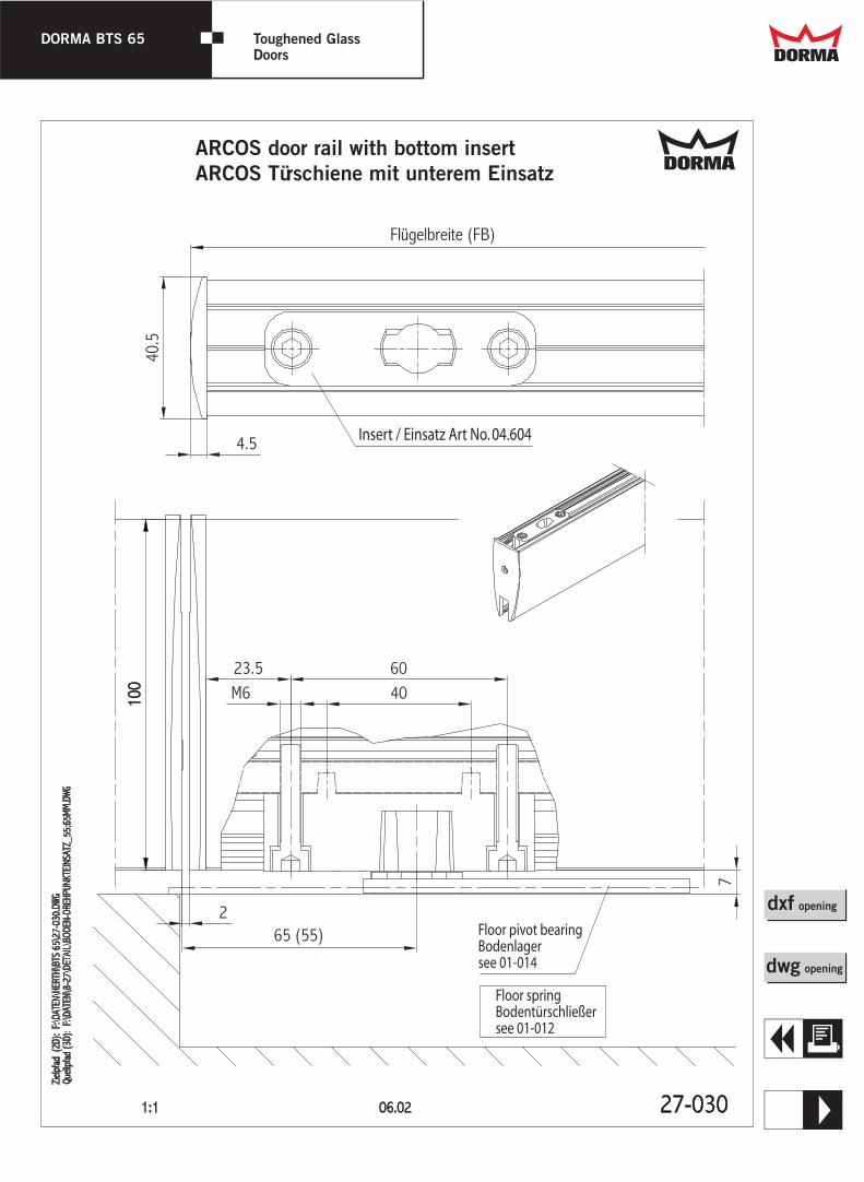
DdARCOS door rail with bottom insert ARCOS Türschiene mit unterem Einsatz

DORMA BTS 65 Toughened GlassDoors Dd
R
Q
dwg opening
dxf opening
DdARCOS door rail with bottom strap in torged steel ARCOS Türschiene mit unterem Stahltürhebel
DORMA-Glas 800.52.109.6.32 Stand/Issue 09/02 Seite/Page 1/1
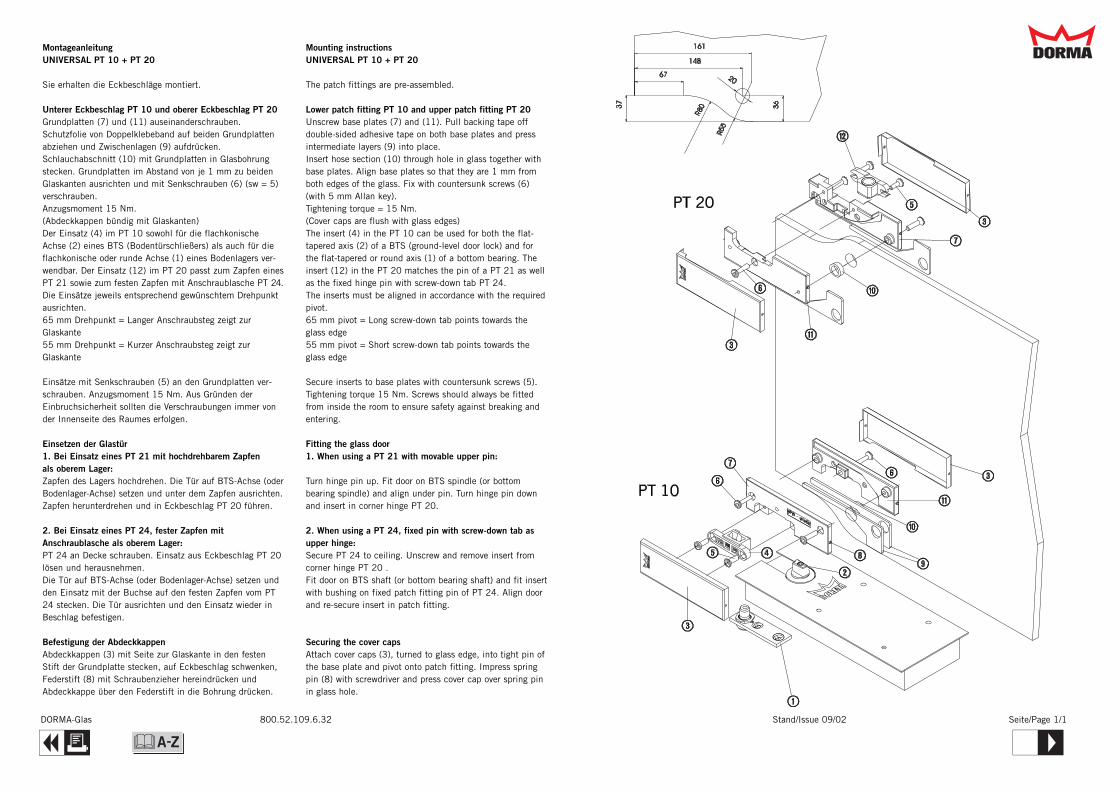
MontageanleitungUNIVERSAL PT 10 + PT 20
Sie erhalten die Eckbeschläge montiert.
Unterer Eckbeschlag PT 10 und oberer Eckbeschlag PT 20 Grundplatten (7) und (11) auseinanderschrauben.Schutzfolie von Doppelklebeband auf beiden Grundplattenabziehen und Zwischenlagen (9) aufdrücken.Schlauchabschnitt (10) mit Grundplatten in Glasbohrungstecken. Grundplatten im Abstand von je 1 mm zu beidenGlaskanten ausrichten und mit Senkschrauben (6) (sw = 5)verschrauben.Anzugsmoment 15 Nm.(Abdeckkappen bündig mit Glaskanten)Der Einsatz (4) im PT 10 sowohl für die flachkonischeAchse (2) eines BTS (Bodentürschließers) als auch für dieflachkonische oder runde Achse (1) eines Bodenlagers ver-wendbar. Der Einsatz (12) im PT 20 passt zum Zapfen einesPT 21 sowie zum festen Zapfen mit Anschraublasche PT 24.Die Einsätze jeweils entsprechend gewünschtem Drehpunktausrichten.65 mm Drehpunkt = Langer Anschraubsteg zeigt zurGlaskante55 mm Drehpunkt = Kurzer Anschraubsteg zeigt zurGlaskante
Einsätze mit Senkschrauben (5) an den Grundplatten ver-schrauben. Anzugsmoment 15 Nm. Aus Gründen derEinbruchsicherheit sollten die Verschraubungen immer vonder Innenseite des Raumes erfolgen.
Einsetzen der Glastür1. Bei Einsatz eines PT 21 mit hochdrehbarem Zapfen als oberem Lager:Zapfen des Lagers hochdrehen. Die Tür auf BTS-Achse (oderBodenlager-Achse) setzen und unter dem Zapfen ausrichten.Zapfen herunterdrehen und in Eckbeschlag PT 20 führen.
2. Bei Einsatz eines PT 24, fester Zapfen mitAnschraublasche als oberem Lager:PT 24 an Decke schrauben. Einsatz aus Eckbeschlag PT 20lösen und herausnehmen. Die Tür auf BTS-Achse (oder Bodenlager-Achse) setzen undden Einsatz mit der Buchse auf den festen Zapfen vom PT24 stecken. Die Tür ausrichten und den Einsatz wieder inBeschlag befestigen.
Befestigung der AbdeckkappenAbdeckkappen (3) mit Seite zur Glaskante in den festenStift der Grundplatte stecken, auf Eckbeschlag schwenken,Federstift (8) mit Schraubenzieher hereindrücken undAbdeckkappe über den Federstift in die Bohrung drücken.
Mounting instructionsUNIVERSAL PT 10 + PT 20
The patch fittings are pre-assembled.
Lower patch fitting PT 10 and upper patch fitting PT 20 Unscrew base plates (7) and (11). Pull backing tape offdouble-sided adhesive tape on both base plates and pressintermediate layers (9) into place.Insert hose section (10) through hole in glass together withbase plates. Align base plates so that they are 1 mm fromboth edges of the glass. Fix with countersunk screws (6)(with 5 mm Allan key).Tightening torque = 15 Nm.(Cover caps are flush with glass edges)The insert (4) in the PT 10 can be used for both the flat-tapered axis (2) of a BTS (ground-level door lock) and forthe flat-tapered or round axis (1) of a bottom bearing. Theinsert (12) in the PT 20 matches the pin of a PT 21 as wellas the fixed hinge pin with screw-down tab PT 24.The inserts must be aligned in accordance with the requiredpivot.65 mm pivot = Long screw-down tab points towards theglass edge55 mm pivot = Short screw-down tab points towards theglass edge
Secure inserts to base plates with countersunk screws (5).Tightening torque 15 Nm. Screws should always be fittedfrom inside the room to ensure safety against breaking andentering.
Fitting the glass door1. When using a PT 21 with movable upper pin:
Turn hinge pin up. Fit door on BTS spindle (or bottombearing spindle) and align under pin. Turn hinge pin downand insert in corner hinge PT 20.
2. When using a PT 24, fixed pin with screw-down tab asupper hinge:Secure PT 24 to ceiling. Unscrew and remove insert fromcorner hinge PT 20 .Fit door on BTS shaft (or bottom bearing shaft) and fit insertwith bushing on fixed patch fitting pin of PT 24. Align doorand re-secure insert in patch fitting.
Securing the cover capsAttach cover caps (3), turned to glass edge, into tight pin ofthe base plate and pivot onto patch fitting. Impress springpin (8) with screwdriver and press cover cap over spring pinin glass hole.
Dd
Q T&
DORMA-Glas 800.52.060.6.32 Stand/Issue 05/02 Seite/Page 1/1
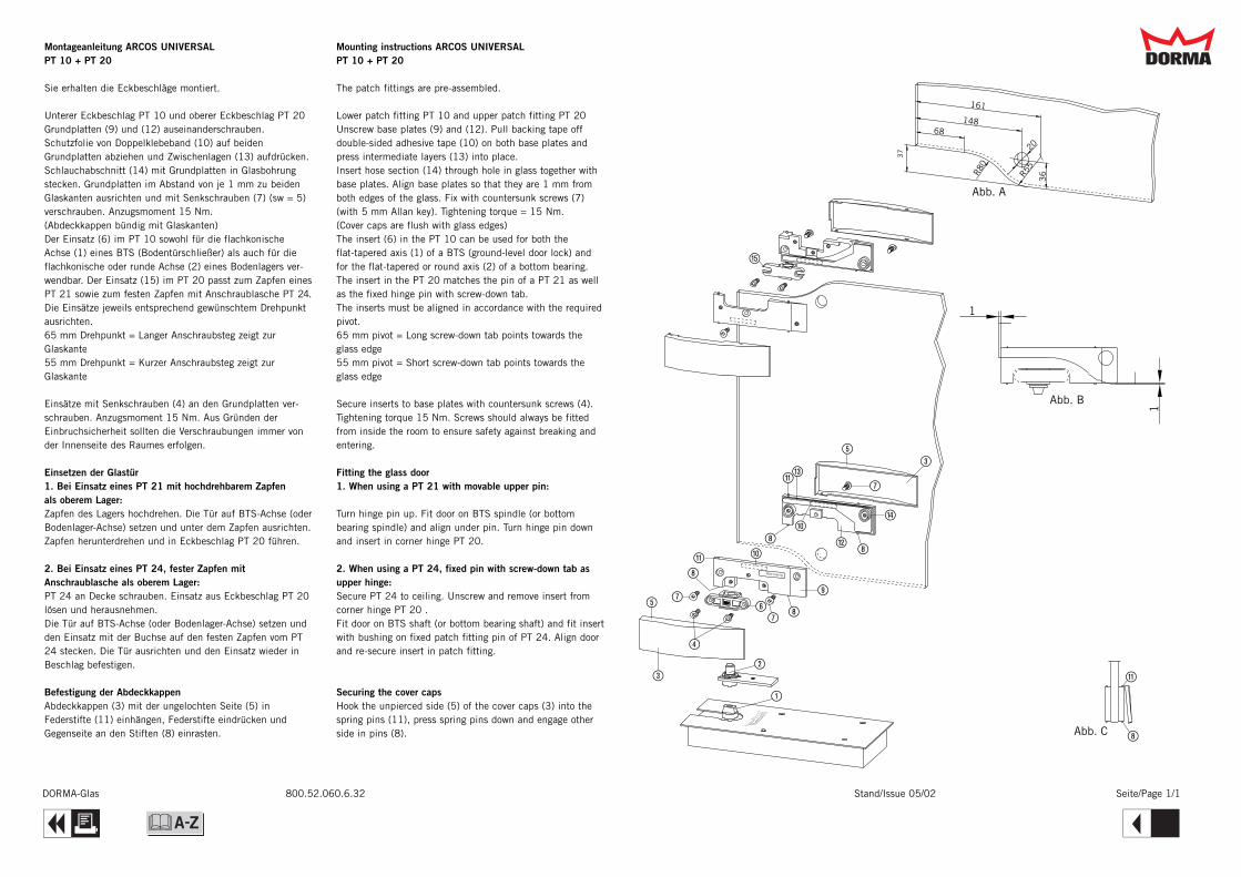
Montageanleitung ARCOS UNIVERSALPT 10 + PT 20
Sie erhalten die Eckbeschläge montiert.
Unterer Eckbeschlag PT 10 und oberer Eckbeschlag PT 20 Grundplatten (9) und (12) auseinanderschrauben.Schutzfolie von Doppelklebeband (10) auf beidenGrundplatten abziehen und Zwischenlagen (13) aufdrücken.Schlauchabschnitt (14) mit Grundplatten in Glasbohrungstecken. Grundplatten im Abstand von je 1 mm zu beidenGlaskanten ausrichten und mit Senkschrauben (7) (sw = 5)verschrauben. Anzugsmoment 15 Nm.(Abdeckkappen bündig mit Glaskanten)Der Einsatz (6) im PT 10 sowohl für die flachkonischeAchse (1) eines BTS (Bodentürschließer) als auch für dieflachkonische oder runde Achse (2) eines Bodenlagers ver-wendbar. Der Einsatz (15) im PT 20 passt zum Zapfen einesPT 21 sowie zum festen Zapfen mit Anschraublasche PT 24.Die Einsätze jeweils entsprechend gewünschtem Drehpunktausrichten.65 mm Drehpunkt = Langer Anschraubsteg zeigt zurGlaskante55 mm Drehpunkt = Kurzer Anschraubsteg zeigt zurGlaskante
Einsätze mit Senkschrauben (4) an den Grundplatten ver-schrauben. Anzugsmoment 15 Nm. Aus Gründen derEinbruchsicherheit sollten die Verschraubungen immer vonder Innenseite des Raumes erfolgen.
Einsetzen der Glastür1. Bei Einsatz eines PT 21 mit hochdrehbarem Zapfen als oberem Lager:Zapfen des Lagers hochdrehen. Die Tür auf BTS-Achse (oderBodenlager-Achse) setzen und unter dem Zapfen ausrichten.Zapfen herunterdrehen und in Eckbeschlag PT 20 führen.
2. Bei Einsatz eines PT 24, fester Zapfen mitAnschraublasche als oberem Lager:PT 24 an Decke schrauben. Einsatz aus Eckbeschlag PT 20lösen und herausnehmen. Die Tür auf BTS-Achse (oder Bodenlager-Achse) setzen undden Einsatz mit der Buchse auf den festen Zapfen vom PT24 stecken. Die Tür ausrichten und den Einsatz wieder inBeschlag befestigen.
Befestigung der AbdeckkappenAbdeckkappen (3) mit der ungelochten Seite (5) inFederstifte (11) einhängen, Federstifte eindrücken undGegenseite an den Stiften (8) einrasten.
Mounting instructions ARCOS UNIVERSALPT 10 + PT 20
The patch fittings are pre-assembled.
Lower patch fitting PT 10 and upper patch fitting PT 20 Unscrew base plates (9) and (12). Pull backing tape offdouble-sided adhesive tape (10) on both base plates andpress intermediate layers (13) into place.Insert hose section (14) through hole in glass together withbase plates. Align base plates so that they are 1 mm fromboth edges of the glass. Fix with countersunk screws (7)(with 5 mm Allan key). Tightening torque = 15 Nm.(Cover caps are flush with glass edges)The insert (6) in the PT 10 can be used for both theflat-tapered axis (1) of a BTS (ground-level door lock) andfor the flat-tapered or round axis (2) of a bottom bearing.The insert in the PT 20 matches the pin of a PT 21 as wellas the fixed hinge pin with screw-down tab.The inserts must be aligned in accordance with the requiredpivot.65 mm pivot = Long screw-down tab points towards theglass edge55 mm pivot = Short screw-down tab points towards theglass edge
Secure inserts to base plates with countersunk screws (4).Tightening torque 15 Nm. Screws should always be fittedfrom inside the room to ensure safety against breaking andentering.
Fitting the glass door1. When using a PT 21 with movable upper pin:
Turn hinge pin up. Fit door on BTS spindle (or bottombearing spindle) and align under pin. Turn hinge pin downand insert in corner hinge PT 20.
2. When using a PT 24, fixed pin with screw-down tab asupper hinge:Secure PT 24 to ceiling. Unscrew and remove insert fromcorner hinge PT 20 .Fit door on BTS shaft (or bottom bearing shaft) and fit insertwith bushing on fixed patch fitting pin of PT 24. Align doorand re-secure insert in patch fitting.
Securing the cover capsHook the unpierced side (5) of the cover caps (3) into thespring pins (11), press spring pins down and engage otherside in pins (8).
Dd
Q R&

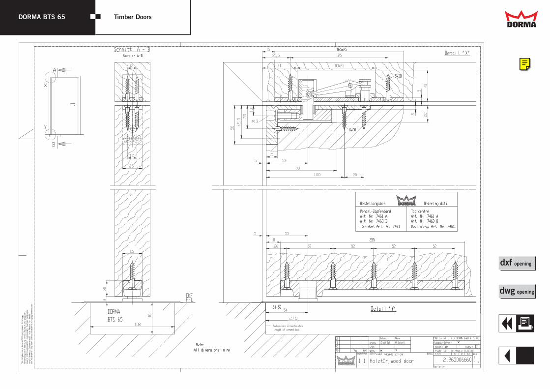
DORMA BTS 65 Timber Doors Dd
T
Q
dwg opening
dxf opening
&

DORMA BTS 65 Timber Doors Dd
E
Q
dwg opening
dxf opening
DORMA BTS 65 Timber Doors Dd
R
Q
dwg opening
dxf opening

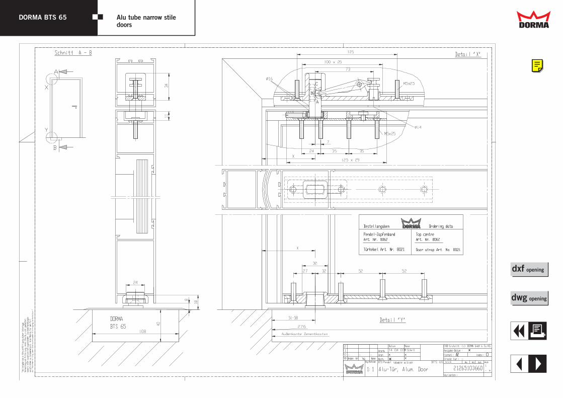
DORMA BTS 65 Alu tube narrow stiledoors Dd
T
Q
dwg opening
dxf opening
&
DORMA BTS 65 Alu tube narrow stiledoors Dd
E
Q
dwg opening
dxf opening

DORMA BTS 65 Alu tube narrow stiledoors Dd
R
Q
dwg opening
dxf opening
Floor SpringAccessories
BTSAccessories
DORMA
Dd
T
&
W
Floor springaccessories
Single actionaluminium doors
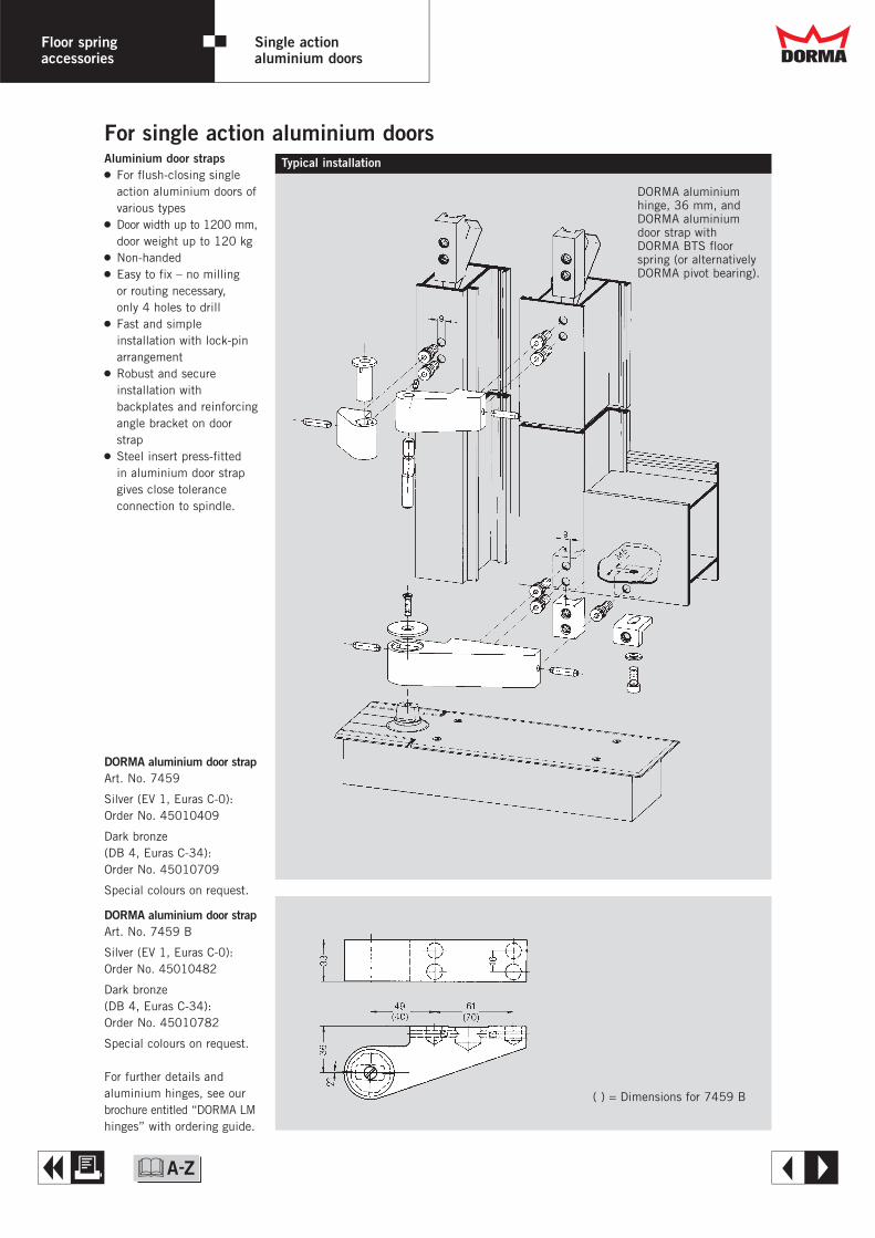
Aluminium door straps2 For flush-closing single
action aluminium doors ofvarious types
2 Door width up to 1200 mm,door weight up to 120 kg
2 Non-handed2 Easy to fix – no milling
or routing necessary,only 4 holes to drill
2 Fast and simpleinstallation with lock-pinarrangement
2 Robust and secureinstallation withbackplates and reinforcingangle bracket on doorstrap
2 Steel insert press-fittedin aluminium door strapgives close toleranceconnection to spindle.
DORMA aluminium door strapArt. No. 7459
Silver (EV 1, Euras C-0):Order No. 45010409
Dark bronze(DB 4, Euras C-34):Order No. 45010709
Special colours on request.
DORMA aluminium door strapArt. No. 7459 B
Silver (EV 1, Euras C-0):Order No. 45010482
Dark bronze (DB 4, Euras C-34):Order No. 45010782
Special colours on request.
For further details andaluminium hinges, see ourbrochure entitled “DORMA LMhinges” with ordering guide.
For single action aluminium doorsTypical installation
DORMA aluminiumhinge, 36 mm, andDORMA aluminiumdoor strap with DORMA BTS floorspring (or alternativelyDORMA pivot bearing).
( ) = Dimensions for 7459 B
Dd
A E&

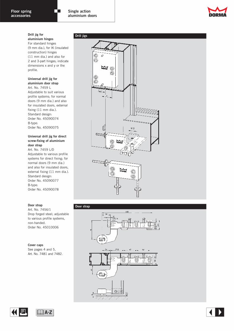
Drill jigsDrill jig for aluminium hingesFor standard hinges(9 mm dia.), for IK (insulatedconstruction) hinges (11 mm dia.) and also for 2 and 3-part hinges; indicatedimensions x and y or theprofile.
Universal drill jig for aluminium door strapArt. No. 7459 LAdjustable to suit variousprofile systems; for normaldoors (9 mm dia.) and alsofor insulated doors, externalfixing (11 mm dia.).Standard design:Order No. 45090074B-type:Order No. 45090075
Universal drill jig for directscrew-fixing of aluminiumdoor strap Art. No. 7459 L/DAdjustable to various profilesystems for direct fixing; fornormal doors (9 mm dia.)and also for insulated doors,external fixing (11 mm dia.).Standard design:Order No. 45090077B-type:Order No. 45090078
Door strapArt. No. 7456/1Drop forged steel; adjustableto various profile systems,non-handed.Order No. 45010006
Cover capsSee pages 4 and 5,Art. No. 7481 and 7482.
Door strap
FFL
Dd
A E
Floor springaccessories
Single actionaluminium doors
&

Floor springaccessories
Single actiontimber doors
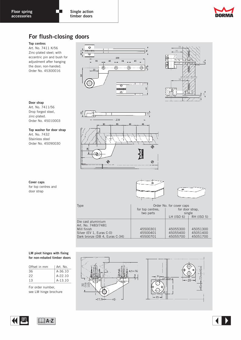
Top centresArt. No. 7411 K/56Zinc-plated steel; witheccentric pin and bush foradjustment after hangingthe door; non-handed.Order No. 45300016
Door strapArt. No. 7411/56Drop forged steel,zinc-plated.Order No. 45010003
Top washer for door strapArt. No. 7432Stainless steelOrder No. 45090030
For flush-closing doors
Cover capsfor top centres and door strap
56
36
56
8
2316
LM pivot hinges with fixingfor non-rebated timber doors
Offset in mm Art. No.36 A-36.1022 A-22.1013 A-13.10
For order number,see LM hinge brochure
Type Order No. for cover capsfor top centres, for door strap,
two parts singleLH (ISO 6) RH (ISO 5)
Die cast aluminiumArt. No. 7483/7481Mill finish 45500301 45055300 45051300Silver (EV 1, Euras C-0) 45500401 45055400 45051400Dark bronze (DB 4, Euras C-34) 45500701 45055700 45051700
Dd
A E&
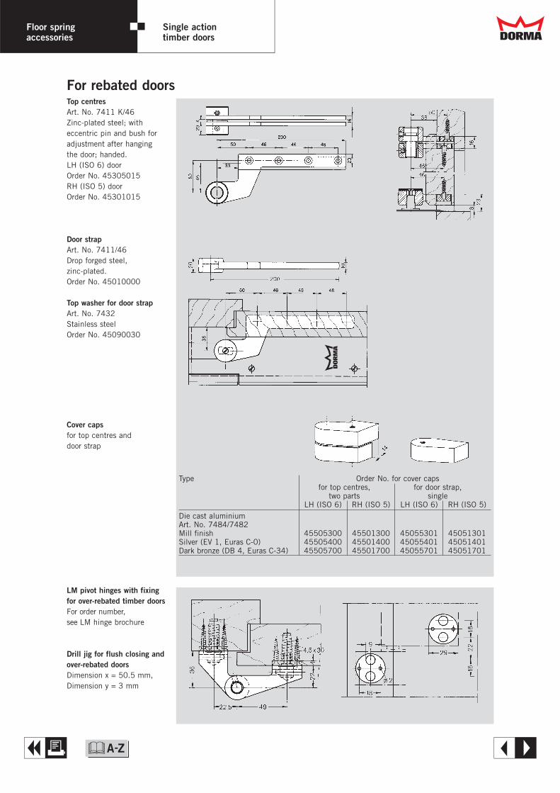
For rebated doorsTop centresArt. No. 7411 K/46Zinc-plated steel; witheccentric pin and bush foradjustment after hangingthe door; handed.LH (ISO 6) doorOrder No. 45305015RH (ISO 5) door Order No. 45301015
Door strapArt. No. 7411/46Drop forged steel,zinc-plated.Order No. 45010000
Top washer for door strapArt. No. 7432Stainless steelOrder No. 45090030
LM pivot hinges with fixingfor over-rebated timber doorsFor order number,see LM hinge brochure
Drill jig for flush closing andover-rebated doorsDimension x = 50.5 mm,Dimension y = 3 mm
Cover capsfor top centres and door strap
Type Order No. for cover capsfor top centres, for door strap,
two parts singleLH (ISO 6) RH (ISO 5) LH (ISO 6) RH (ISO 5)
Die cast aluminiumArt. No. 7484/7482Mill finish 45505300 45501300 45055301 45051301Silver (EV 1, Euras C-0) 45505400 45501400 45055401 45051401Dark bronze (DB 4, Euras C-34) 45505700 45501700 45055701 45051701
DdFloor springaccessories
Single actiontimber doors
A E&
( ) = TS 93 5 – 7
Floor springaccessories
Single action steel doors
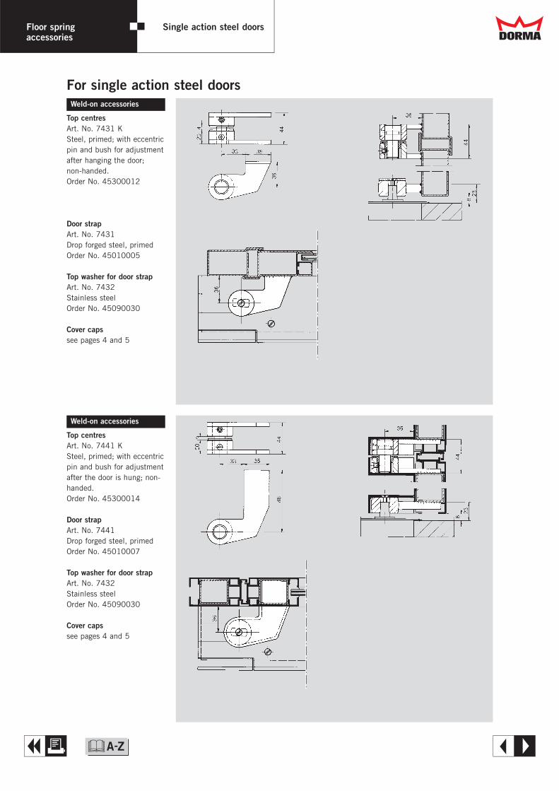
Weld-on accessories
Top centresArt. No. 7431 KSteel, primed; with eccentricpin and bush for adjustmentafter hanging the door;non-handed.Order No. 45300012
Door strapArt. No. 7431Drop forged steel, primedOrder No. 45010005
Top washer for door strapArt. No. 7432Stainless steelOrder No. 45090030
Cover capssee pages 4 and 5
For single action steel doors
Weld-on accessories
Top centresArt. No. 7441 KSteel, primed; with eccentricpin and bush for adjustmentafter the door is hung; non-handed.Order No. 45300014
Door strapArt. No. 7441Drop forged steel, primedOrder No. 45010007
Top washer for door strapArt. No. 7432Stainless steelOrder No. 45090030
Cover capssee pages 4 and 5
Dd
A E&
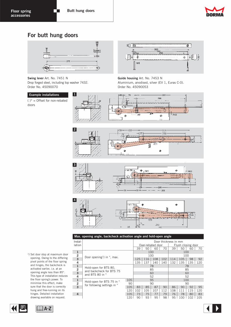
For butt hung doors
Floor springaccessories
Butt hung doors
21(14)*
21 (1 4)**21 (1 4)**
Example installations
( )* = Offset for non-rebateddoors
Swing lever Art. No. 7451 NDrop forged steel, including top washer 7432.Order No. 45090070
Guide housing Art. No. 7453 NAluminium, anodised, silver (EV 1, Euras C-0).Order No. 45090053
Max. opening angle, backcheck activation angle and hold-open angle
Door thickness in mmOver-rebated door Flush closing door
039 050 060 070 039 050 060 070100 100
Door opening1) in °, max. 100 100125 116 108 102 114 105 098 092135 137 140 140 132 135 135 120
Hold-open for BTS 80, 78 78
and backcheck for BTS 75 85 85
and BTS 80 in ° 60 6052 52
Hold-open for BTS 75 in ° 105 95 100
for following settings in ° 90 90 90105 083 085 087 090 086 090 092 095120 102 105 107 112 108 111 115 120105 073 075 077 079 076 078 080 083120 090 093 095 098 095 100 102 105
Instal-lation
12341234123
4
1
3
2
4
1) Set door stop at maximum dooropening. Owing to the differingpivot points of the floor springand hinges, the backcheck isactivated earlier, i.e. at anopening angle less than 85°.This type of installation reducesthe floor spring’s power. Tominimise this effect, makesure that the door is correctlyhung and free-running on itshinges. Detailed installationdrawing available on request.
Dd
A E&

Floor springaccessories
Double action doors
l 15/l 13*
l 15
l 13*± 5
l 13*± 5
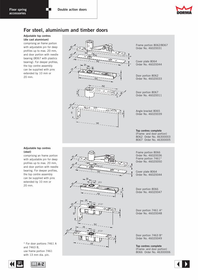
Frame portion 8062/8067Order No. 46020031
Cover plate 8064Order No. 46020044
Door portion 8062Order No. 46020033
Door portion 8067Order No. 46020011
Top centres complete(Frame- and door portion)8062 Order No. 463000038067 Order No. 46300005
Frame portion 8066Order No. 46020036Frame portion 7461*Order No. 46020050
Cover plate 8064Order No. 46020044
Door portion 8066Order No. 46020047
Door portion 7461 A*Order No. 46020048
Door portion 7463 B*Order No. 46020049
Top centres complete(Frame- and door portion)8066 Order No. 46300006
Angle bracket 8065Order No. 46020039
Adjustable top centres(die cast aluminium)comprising an frame portionwith adjustable pin for deepprofiles up to max. 20 mm,and door portion with needlebearing (8067 with plasticsbearing). For deeper profiles,the top centre assemblycan be supplied with pinsextended by 10 mm or20 mm.
Adjustable top centres(steel)comprising an frame portionwith adjustable pin for deepprofiles up to max. 20 mm,and door portion with needlebearing. For deeper profiles,the top centre assemblycan be supplied with pinsextended by 10 mm or20 mm.
* For door portions 7461 Aand 7463 B,use frame portion 7461with 13 mm dia. pin.
For steel, aluminium and timber doors
Dd
A E&
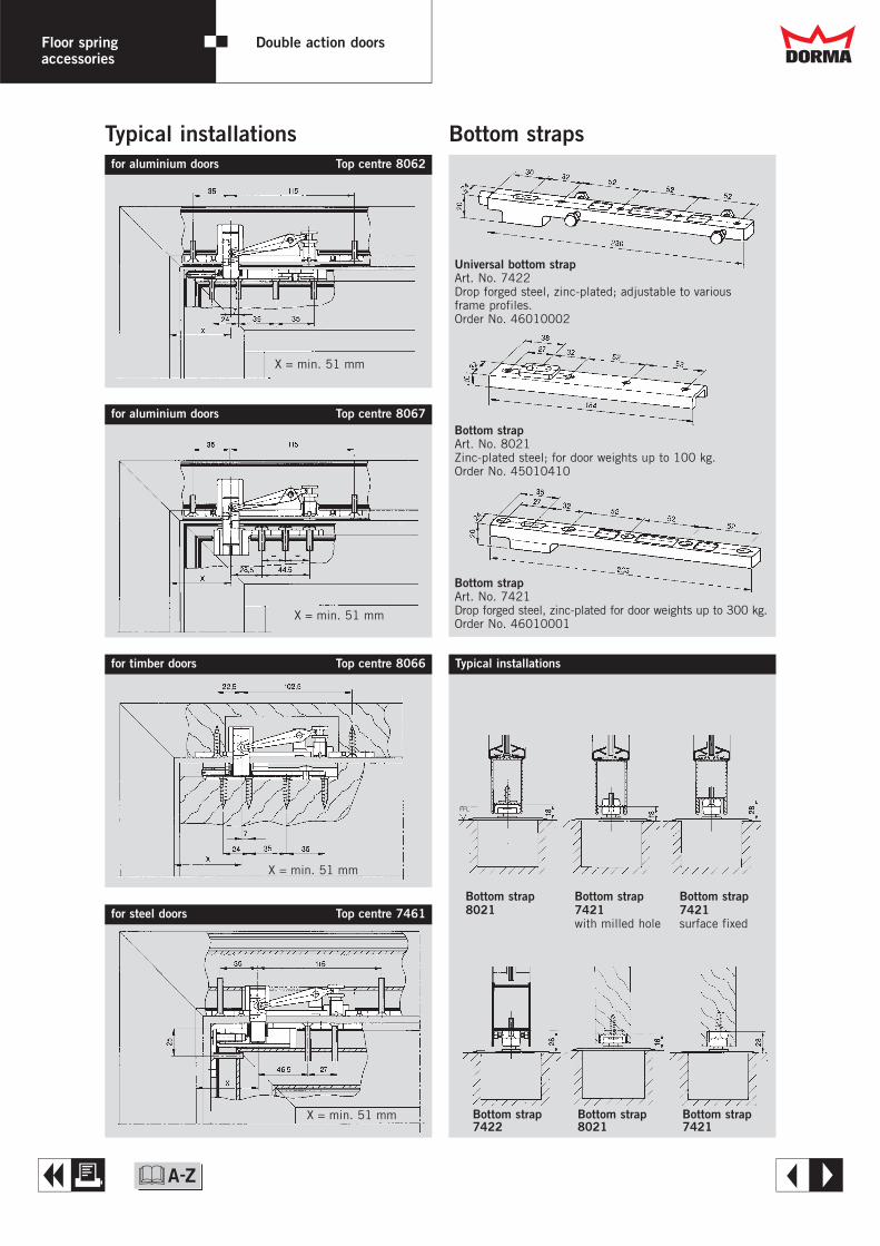
Typical installations Bottom strapsfor aluminium doors Top centre 8062
for aluminium doors Top centre 8067
for timber doors Top centre 8066 Typical installations
for steel doors Top centre 7461
Universal bottom strapArt. No. 7422Drop forged steel, zinc-plated; adjustable to variousframe profiles.Order No. 46010002
Bottom strapArt. No. 8021Zinc-plated steel; for door weights up to 100 kg.Order No. 45010410
Bottom strapArt. No. 7421Drop forged steel, zinc-plated for door weights up to 300 kg.Order No. 46010001
Bottom strap Bottom strap Bottom strap8021 7421 7421
with milled hole surface fixed
X = min. 51 mm
X = min. 51 mm
X = min. 51 mm
X = min. 51 mm Bottom strap Bottom strap Bottom strap 7422 8021 7421
FFL
Floor springaccessories
Double action doors Dd
A E&

DORMA accessories Pivot bearings
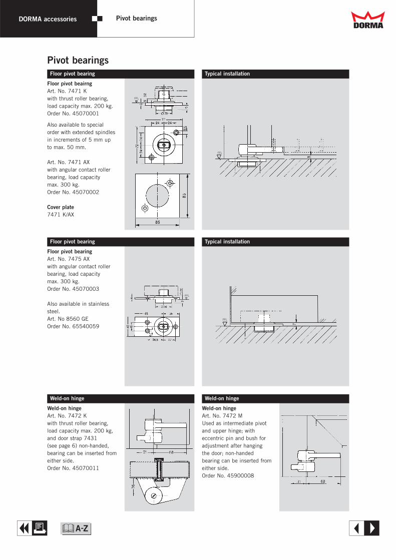
Pivot bearingsFloor pivot bearing
Floor pivot beairngArt. No. 7471 Kwith thrust roller bearing,load capacity max. 200 kg.Order No. 45070001
Also available to specialorder with extended spindlesin increments of 5 mm upto max. 50 mm.
Art. No. 7471 AXwith angular contact rollerbearing, load capacity max. 300 kg.Order No. 45070002
Cover plate7471 K/AX
Floor pivot bearing
Floor pivot bearingArt. No. 7475 AXwith angular contact rollerbearing, load capacity max. 300 kg.Order No. 45070003
Also available in stainlesssteel.Art. No 8560 GEOrder No. 65540059
Weld-on hinge
Weld-on hingeArt. No. 7472 Kwith thrust roller bearing,load capacity max. 200 kg,and door strap 7431 (see page 6) non-handed,bearing can be inserted fromeither side. Order No. 45070011
Weld-on hinge
Weld-on hingeArt. No. 7472 MUsed as intermediate pivotand upper hinge; witheccentric pin and bush foradjustment after hangingthe door; non-handed bearing can be inserted fromeither side.Order No. 45900008
Typical installation
Typical installation
FFL
FFL
FFL
FFL
Dd
A E&

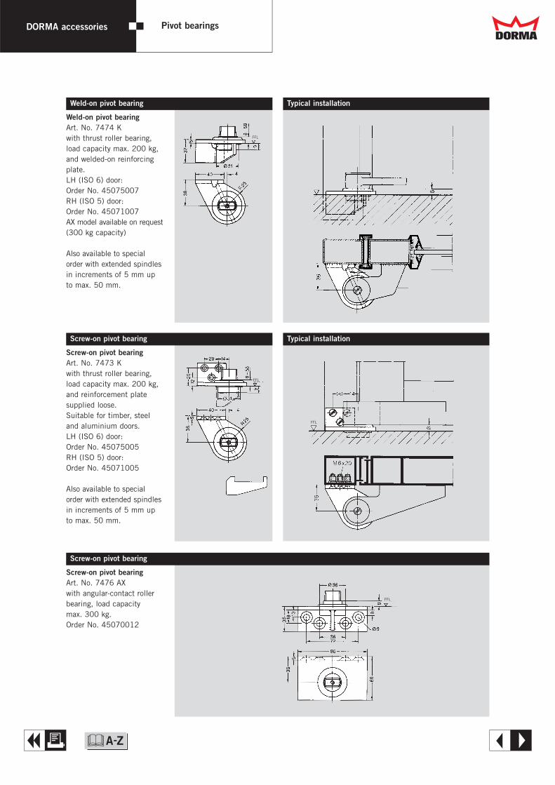
Weld-on pivot bearing Typical installation
Weld-on pivot bearingArt. No. 7474 Kwith thrust roller bearing,load capacity max. 200 kg,and welded-on reinforcingplate.LH (ISO 6) door:Order No. 45075007RH (ISO 5) door:Order No. 45071007AX model available on request(300 kg capacity)
Also available to specialorder with extended spindlesin increments of 5 mm upto max. 50 mm.
Screw-on pivot bearing
Screw-on pivot bearingArt. No. 7473 Kwith thrust roller bearing,load capacity max. 200 kg,and reinforcement platesupplied loose.Suitable for timber, steeland aluminium doors.LH (ISO 6) door:Order No. 45075005RH (ISO 5) door:Order No. 45071005
Also available to specialorder with extended spindlesin increments of 5 mm upto max. 50 mm.
Typical installation
OKFF
Screw-on pivot bearingArt. No. 7476 AXwith angular-contact rollerbearing, load capacity max. 300 kg.Order No. 45070012
Screw-on pivot bearing
FFL
FFL
FFL
FFL
DORMA accessories Pivot bearings Dd
A E&
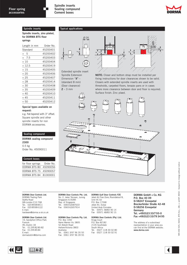
Spindle inserts, zinc-plated,for DORMA BTS floorsprings
Length in mm Order No.
Standard 45200401
+ 5 45200402
+ 7.5 45200403
+ 10 45200404
+ 12.5 45200419
+ 15 45200405
+ 20 45200406
+ 25 45200407
+ 28 45200414
+ 30 45200408
+ 35 45200409
+ 40 45200410
+ 45 45200411
+ 50 45200412
Special types available onrequest:e.g. flat-tapered with 3° offset.Square spindle and otherspindle inserts for nonDORMA accessories.
DORMA sealing compound23000.5 kgOrder No. 45090011
for floor springs Order No.DORMA BTS 80 45090056
DORMA BTS 75 45090057
DORMA BTS 84 81000001
Floor springaccessories
Spindle insertsSealing compoundCement boxes
Spindle inserts
Sealing compound
Cement boxes
Typical applications
Extended spindle insert Spindle ExtensionDimension “X” –(standard 8 mm)(Door clearance)Z – 3 mm
WN
05
0 9
25
, 0
6/0
2,
BTS
Acc
., G
B,
x. x
x/C
tP,
XX/0
2 ·
Sub
ject
to
chan
ge w
itho
ut n
otic
e
NOTE: Closer and bottom strap must be installed perfixing instructions for door clearances shown to be valid.Closers with extended spindle inserts are used withthresholds, carpeted floors, terazzo pans or in caseswhere more clearance between door and floor is required.Surface finish: Zinc plaed.
DORMA GmbH + Co. KGP.O. Box 40 09D-58247 EnnepetalBreckerfelder Straße 42-48D-58256 EnnepetalGermanyTel. +49(0)23 33/793-0Fax +49(0)23 33/79 34 95
The address of a subsidiary/representation in your area youcan find at the DORMA website:www.dorma.com
DORMA Gulf Door Controls FZEJebel Ali Free Zone, Roundabout 8,Unit VC 02P.O. Box 17268Jebel Ali, Dubai United Arab EmiratesTel. 00971 48/83 90 14Fax 00971 48/83 90 15
DORMA Door Controls (Pty.) Ltd.Kings CourtP.O. Box 821822135 SouthdaleSouth AfricaTel. 0027 11/8 30 02 80Fax 0027 11/8 30 02 91
DORMA Door Controls Ltd.DORMA Trading ParkStaffa RoadGB-London E10 7QXTel. 020 8558 8411Fax 020 8558 6122E-mail:hardware@dorma a-uk.co.uk
DORMA Door Controls Ltd.19, Sandyford Office ParkFoxrockIRL-Dublin 18Tel. 01 295 82 80-82Fax 01 295 85 84E-mail:[email protected]
DORMA Door Controls Pte. Ltd.No. 2, Jalan Terusan, JurongSingapore 619285Rep. of SingaporeTel. 0065 62687633Fax 0065 62657914
DORMA Door Controls Pty. Ltd.P.O. Box 1092Narre Warren Vic 380552 Abbott RoadHallam/Victoria 3803AustraliaTel. 0061 3/97 96 35 55Fax 0061 3/97 96 39 55
Dd
A R&

Floor SpringAccessories
BTSAccessories
DORMA
Dd
T
&
W

Floor springaccessories
Single actionaluminium doors
Aluminium door straps2 For flush-closing single
action aluminium doors ofvarious types
2 Door width up to 1200 mm,door weight up to 120 kg
2 Non-handed2 Easy to fix – no milling
or routing necessary,only 4 holes to drill
2 Fast and simpleinstallation with lock-pinarrangement
2 Robust and secureinstallation withbackplates and reinforcingangle bracket on doorstrap
2 Steel insert press-fittedin aluminium door strapgives close toleranceconnection to spindle.
DORMA aluminium door strapArt. No. 7459
Silver (EV 1, Euras C-0):Order No. 45010409
Dark bronze(DB 4, Euras C-34):Order No. 45010709
Special colours on request.
DORMA aluminium door strapArt. No. 7459 B
Silver (EV 1, Euras C-0):Order No. 45010482
Dark bronze (DB 4, Euras C-34):Order No. 45010782
Special colours on request.
For further details andaluminium hinges, see ourbrochure entitled “DORMA LMhinges” with ordering guide.
For single action aluminium doorsTypical installation
DORMA aluminiumhinge, 36 mm, andDORMA aluminiumdoor strap with DORMA BTS floorspring (or alternativelyDORMA pivot bearing).
( ) = Dimensions for 7459 B
Dd
A E&
Drill jigsDrill jig for aluminium hingesFor standard hinges(9 mm dia.), for IK (insulatedconstruction) hinges (11 mm dia.) and also for 2 and 3-part hinges; indicatedimensions x and y or theprofile.
Universal drill jig for aluminium door strapArt. No. 7459 LAdjustable to suit variousprofile systems; for normaldoors (9 mm dia.) and alsofor insulated doors, externalfixing (11 mm dia.).Standard design:Order No. 45090074B-type:Order No. 45090075
Universal drill jig for directscrew-fixing of aluminiumdoor strap Art. No. 7459 L/DAdjustable to various profilesystems for direct fixing; fornormal doors (9 mm dia.)and also for insulated doors,external fixing (11 mm dia.).Standard design:Order No. 45090077B-type:Order No. 45090078
Door strapArt. No. 7456/1Drop forged steel; adjustableto various profile systems,non-handed.Order No. 45010006
Cover capsSee pages 4 and 5,Art. No. 7481 and 7482.
Door strap
FFL
Dd
A E
Floor springaccessories
Single actionaluminium doors
&
Floor springaccessories
Single actiontimber doors
Top centresArt. No. 7411 K/56Zinc-plated steel; witheccentric pin and bush foradjustment after hangingthe door; non-handed.Order No. 45300016
Door strapArt. No. 7411/56Drop forged steel,zinc-plated.Order No. 45010003
Top washer for door strapArt. No. 7432Stainless steelOrder No. 45090030
For flush-closing doors
Cover capsfor top centres and door strap
56
36
56
8
2316
LM pivot hinges with fixingfor non-rebated timber doors
Offset in mm Art. No.36 A-36.1022 A-22.1013 A-13.10
For order number,see LM hinge brochure
Type Order No. for cover capsfor top centres, for door strap,
two parts singleLH (ISO 6) RH (ISO 5)
Die cast aluminiumArt. No. 7483/7481Mill finish 45500301 45055300 45051300Silver (EV 1, Euras C-0) 45500401 45055400 45051400Dark bronze (DB 4, Euras C-34) 45500701 45055700 45051700
Dd
A E&

For rebated doorsTop centresArt. No. 7411 K/46Zinc-plated steel; witheccentric pin and bush foradjustment after hangingthe door; handed.LH (ISO 6) doorOrder No. 45305015RH (ISO 5) door Order No. 45301015
Door strapArt. No. 7411/46Drop forged steel,zinc-plated.Order No. 45010000
Top washer for door strapArt. No. 7432Stainless steelOrder No. 45090030
LM pivot hinges with fixingfor over-rebated timber doorsFor order number,see LM hinge brochure
Drill jig for flush closing andover-rebated doorsDimension x = 50.5 mm,Dimension y = 3 mm
Cover capsfor top centres and door strap
Type Order No. for cover capsfor top centres, for door strap,
two parts singleLH (ISO 6) RH (ISO 5) LH (ISO 6) RH (ISO 5)
Die cast aluminiumArt. No. 7484/7482Mill finish 45505300 45501300 45055301 45051301Silver (EV 1, Euras C-0) 45505400 45501400 45055401 45051401Dark bronze (DB 4, Euras C-34) 45505700 45501700 45055701 45051701
DdFloor springaccessories
Single actiontimber doors
A E&

( ) = TS 93 5 – 7
Floor springaccessories
Single action steel doors
Weld-on accessories
Top centresArt. No. 7431 KSteel, primed; with eccentricpin and bush for adjustmentafter hanging the door;non-handed.Order No. 45300012
Door strapArt. No. 7431Drop forged steel, primedOrder No. 45010005
Top washer for door strapArt. No. 7432Stainless steelOrder No. 45090030
Cover capssee pages 4 and 5
For single action steel doors
Weld-on accessories
Top centresArt. No. 7441 KSteel, primed; with eccentricpin and bush for adjustmentafter the door is hung; non-handed.Order No. 45300014
Door strapArt. No. 7441Drop forged steel, primedOrder No. 45010007
Top washer for door strapArt. No. 7432Stainless steelOrder No. 45090030
Cover capssee pages 4 and 5
Dd
A E&

For butt hung doors
Floor springaccessories
Butt hung doors
21(14)*
21 (1 4)**21 (1 4)**
Example installations
( )* = Offset for non-rebateddoors
Swing lever Art. No. 7451 NDrop forged steel, including top washer 7432.Order No. 45090070
Guide housing Art. No. 7453 NAluminium, anodised, silver (EV 1, Euras C-0).Order No. 45090053
Max. opening angle, backcheck activation angle and hold-open angle
Door thickness in mmOver-rebated door Flush closing door
039 050 060 070 039 050 060 070100 100
Door opening1) in °, max. 100 100125 116 108 102 114 105 098 092135 137 140 140 132 135 135 120
Hold-open for BTS 80, 78 78
and backcheck for BTS 75 85 85
and BTS 80 in ° 60 6052 52
Hold-open for BTS 75 in ° 105 95 100
for following settings in ° 90 90 90105 083 085 087 090 086 090 092 095120 102 105 107 112 108 111 115 120105 073 075 077 079 076 078 080 083120 090 093 095 098 095 100 102 105
Instal-lation
12341234123
4
1
3
2
4
1) Set door stop at maximum dooropening. Owing to the differingpivot points of the floor springand hinges, the backcheck isactivated earlier, i.e. at anopening angle less than 85°.This type of installation reducesthe floor spring’s power. Tominimise this effect, makesure that the door is correctlyhung and free-running on itshinges. Detailed installationdrawing available on request.
Dd
A E&
Floor springaccessories
Double action doors
l 15/l 13*
l 15
l 13*± 5
l 13*± 5
Frame portion 8062/8067Order No. 46020031
Cover plate 8064Order No. 46020044
Door portion 8062Order No. 46020033
Door portion 8067Order No. 46020011
Top centres complete(Frame- and door portion)8062 Order No. 463000038067 Order No. 46300005
Frame portion 8066Order No. 46020036Frame portion 7461*Order No. 46020050
Cover plate 8064Order No. 46020044
Door portion 8066Order No. 46020047
Door portion 7461 A*Order No. 46020048
Door portion 7463 B*Order No. 46020049
Top centres complete(Frame- and door portion)8066 Order No. 46300006
Angle bracket 8065Order No. 46020039
Adjustable top centres(die cast aluminium)comprising an frame portionwith adjustable pin for deepprofiles up to max. 20 mm,and door portion with needlebearing (8067 with plasticsbearing). For deeper profiles,the top centre assemblycan be supplied with pinsextended by 10 mm or20 mm.
Adjustable top centres(steel)comprising an frame portionwith adjustable pin for deepprofiles up to max. 20 mm,and door portion with needlebearing. For deeper profiles,the top centre assemblycan be supplied with pinsextended by 10 mm or20 mm.
* For door portions 7461 Aand 7463 B,use frame portion 7461with 13 mm dia. pin.
For steel, aluminium and timber doors
Dd
A E&

Typical installations Bottom strapsfor aluminium doors Top centre 8062
for aluminium doors Top centre 8067
for timber doors Top centre 8066 Typical installations
for steel doors Top centre 7461
Universal bottom strapArt. No. 7422Drop forged steel, zinc-plated; adjustable to variousframe profiles.Order No. 46010002
Bottom strapArt. No. 8021Zinc-plated steel; for door weights up to 100 kg.Order No. 45010410
Bottom strapArt. No. 7421Drop forged steel, zinc-plated for door weights up to 300 kg.Order No. 46010001
Bottom strap Bottom strap Bottom strap8021 7421 7421
with milled hole surface fixed
X = min. 51 mm
X = min. 51 mm
X = min. 51 mm
X = min. 51 mm Bottom strap Bottom strap Bottom strap 7422 8021 7421
FFL
Floor springaccessories
Double action doors Dd
A E&
DORMA accessories Pivot bearings
Pivot bearingsFloor pivot bearing
Floor pivot beairngArt. No. 7471 Kwith thrust roller bearing,load capacity max. 200 kg.Order No. 45070001
Also available to specialorder with extended spindlesin increments of 5 mm upto max. 50 mm.
Art. No. 7471 AXwith angular contact rollerbearing, load capacity max. 300 kg.Order No. 45070002
Cover plate7471 K/AX
Floor pivot bearing
Floor pivot bearingArt. No. 7475 AXwith angular contact rollerbearing, load capacity max. 300 kg.Order No. 45070003
Also available in stainlesssteel.Art. No 8560 GEOrder No. 65540059
Weld-on hinge
Weld-on hingeArt. No. 7472 Kwith thrust roller bearing,load capacity max. 200 kg,and door strap 7431 (see page 6) non-handed,bearing can be inserted fromeither side. Order No. 45070011
Weld-on hinge
Weld-on hingeArt. No. 7472 MUsed as intermediate pivotand upper hinge; witheccentric pin and bush foradjustment after hangingthe door; non-handed bearing can be inserted fromeither side.Order No. 45900008
Typical installation
Typical installation
FFL
FFL
FFL
FFL
Dd
A E&
Weld-on pivot bearing Typical installation
Weld-on pivot bearingArt. No. 7474 Kwith thrust roller bearing,load capacity max. 200 kg,and welded-on reinforcingplate.LH (ISO 6) door:Order No. 45075007RH (ISO 5) door:Order No. 45071007AX model available on request(300 kg capacity)
Also available to specialorder with extended spindlesin increments of 5 mm upto max. 50 mm.
Screw-on pivot bearing
Screw-on pivot bearingArt. No. 7473 Kwith thrust roller bearing,load capacity max. 200 kg,and reinforcement platesupplied loose.Suitable for timber, steeland aluminium doors.LH (ISO 6) door:Order No. 45075005RH (ISO 5) door:Order No. 45071005
Also available to specialorder with extended spindlesin increments of 5 mm upto max. 50 mm.
Typical installation
OKFF
Screw-on pivot bearingArt. No. 7476 AXwith angular-contact rollerbearing, load capacity max. 300 kg.Order No. 45070012
Screw-on pivot bearing
FFL
FFL
FFL
FFL
DORMA accessories Pivot bearings Dd
A E&

Spindle inserts, zinc-plated,for DORMA BTS floorsprings
Length in mm Order No.
Standard 45200401
+ 5 45200402
+ 7.5 45200403
+ 10 45200404
+ 12.5 45200419
+ 15 45200405
+ 20 45200406
+ 25 45200407
+ 28 45200414
+ 30 45200408
+ 35 45200409
+ 40 45200410
+ 45 45200411
+ 50 45200412
Special types available onrequest:e.g. flat-tapered with 3° offset.Square spindle and otherspindle inserts for nonDORMA accessories.
DORMA sealing compound23000.5 kgOrder No. 45090011
for floor springs Order No.DORMA BTS 80 45090056
DORMA BTS 75 45090057
DORMA BTS 84 81000001
Floor springaccessories
Spindle insertsSealing compoundCement boxes
Spindle inserts
Sealing compound
Cement boxes
Typical applications
Extended spindle insert Spindle ExtensionDimension “X” –(standard 8 mm)(Door clearance)Z – 3 mm
WN
05
0 9
25
, 0
6/0
2,
BTS
Acc
., G
B,
x. x
x/C
tP,
XX/0
2 ·
Sub
ject
to
chan
ge w
itho
ut n
otic
e
NOTE: Closer and bottom strap must be installed perfixing instructions for door clearances shown to be valid.Closers with extended spindle inserts are used withthresholds, carpeted floors, terazzo pans or in caseswhere more clearance between door and floor is required.Surface finish: Zinc plaed.
DORMA GmbH + Co. KGP.O. Box 40 09D-58247 EnnepetalBreckerfelder Straße 42-48D-58256 EnnepetalGermanyTel. +49(0)23 33/793-0Fax +49(0)23 33/79 34 95
The address of a subsidiary/representation in your area youcan find at the DORMA website:www.dorma.com
DORMA Gulf Door Controls FZEJebel Ali Free Zone, Roundabout 8,Unit VC 02P.O. Box 17268Jebel Ali, Dubai United Arab EmiratesTel. 00971 48/83 90 14Fax 00971 48/83 90 15
DORMA Door Controls (Pty.) Ltd.Kings CourtP.O. Box 821822135 SouthdaleSouth AfricaTel. 0027 11/8 30 02 80Fax 0027 11/8 30 02 91
DORMA Door Controls Ltd.DORMA Trading ParkStaffa RoadGB-London E10 7QXTel. 020 8558 8411Fax 020 8558 6122E-mail:hardware@dorma a-uk.co.uk
DORMA Door Controls Ltd.19, Sandyford Office ParkFoxrockIRL-Dublin 18Tel. 01 295 82 80-82Fax 01 295 85 84E-mail:[email protected]
DORMA Door Controls Pte. Ltd.No. 2, Jalan Terusan, JurongSingapore 619285Rep. of SingaporeTel. 0065 62687633Fax 0065 62657914
DORMA Door Controls Pty. Ltd.P.O. Box 1092Narre Warren Vic 380552 Abbott RoadHallam/Victoria 3803AustraliaTel. 0061 3/97 96 35 55Fax 0061 3/97 96 39 55
Dd
A R&
Floor spring
BTS 80DORMA
Dd
T
&
W

DORMA BTS 80 Floor spring
Universal application,multi-functional,quality assured
for the trade2 Just one model for virtually
every application.2 All the main functions as
standard for reduced stock-holding.
2 Available with weak orstrong spring for specialapplications.
for the installer2 Non-handed, for single
and double action doors.2 Interchangeable spindle
inserts available to suitsite conditions.
for the architect/specifier2 Concealed installation.2 All the main functions such
as hold-open, delayedaction, backcheck.
2 Proven, robust unit – capable of handling doorsup to 300 kg in weight.
for the user2 Maximum comfort and
safety provided by multi-functional unit.
2 Closing speed unaffectedby temperature changes.
2 Easy door operation due to high mechanicalefficiency.
Plus points
PSA approved (MOB H3 03)HTM 59 (DOH)
60
36
-42
36
-42
51-57
78 341
1
2 3
1 Closing speed adjustmentvalve
2 Hold-open or delayed actionvalve
3 Adjustment screw for varyingthe start of the hold-openrange or the end point of thedelayed action range
Spring strength EN 3 EN 4 EN 6Standard and external ≤ 1950 mm – 2 –doors up to 1) ≤ 1100 mm 2 – –
≤ 1400 mm – – 2
for fire doors2) – – –
Non-handed suitable forsingle and double action doors 2 2 2
Closing speedvariable by valve adjustment 2 2 2
Backcheck, mechanical 2 2 2
Hold-open, hydraulically adjustable 2 2 2
Delayed action variable byvalve adjustment (as an alternative to the hold-open feature) 2 2 2
Weight in kg, approx. 7.1 7.1 7.1
Dimensions in mm Length 341 341 341Width 078 078 078Height 060 060 060
Door closer approved to EN 1154 2 2 2
2 Yes – No
1) For applications involving particularly high or heavy doors,and doors which have to close against wind or draughtconditions, the next larger closer size should be selected.
2) Has been included in successful fire tests to BS 476: Pt 8
See also brochure on BTS 80 F, EMB, FLB floor spings, firedoors.
Technical data BTS 80
Quality-assured manufactureto ISO 9001, EN 29001, BS 5750.Certified and verified by BSI Quality AssuranceReg. No. Q 6423, FM 10756
Dd
A E
1
1
4
4
3
3
2
2
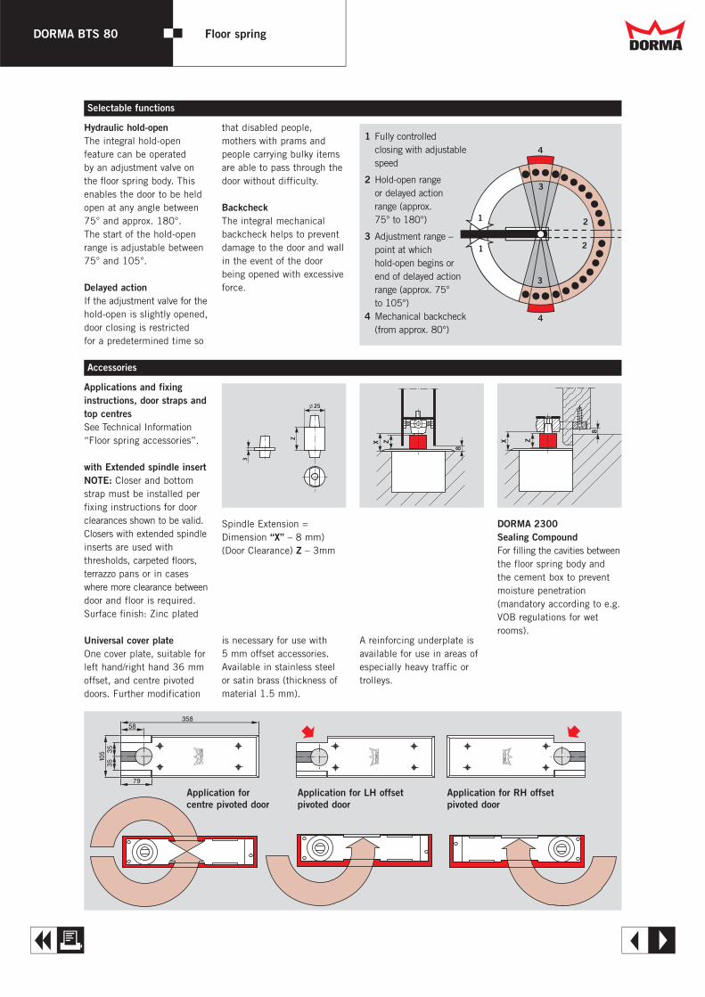
Hydraulic hold-openThe integral hold-open feature can be operated by an adjustment valve onthe floor spring body. Thisenables the door to be heldopen at any angle between75° and approx. 180°. The start of the hold-openrange is adjustable between75° and 105°.
Delayed actionIf the adjustment valve for thehold-open is slightly opened,door closing is restricted for a predetermined time so
that disabled people,mothers with prams andpeople carrying bulky itemsare able to pass through thedoor without difficulty.
BackcheckThe integral mechanicalbackcheck helps to preventdamage to the door and wallin the event of the doorbeing opened with excessiveforce.
1 Fully controlled closing with adjustablespeed
2 Hold-open range or delayed action range (approx. 75° to 180°)
3 Adjustment range –point at which hold-open begins orend of delayed actionrange (approx. 75°to 105°)
4 Mechanical backcheck (from approx. 80°)
X Z
8
X Z
8
Z
3
l 25
Spindle Extension =Dimension “X” – 8 mm)(Door Clearance) Z – 3mm
Applications and fixinginstructions, door straps andtop centresSee Technical Information“Floor spring accessories”.
with Extended spindle insertNOTE: Closer and bottomstrap must be installed perfixing instructions for doorclearances shown to be valid.Closers with extended spindleinserts are used with thresholds, carpeted floors,terrazzo pans or in caseswhere more clearance betweendoor and floor is required.Surface finish: Zinc plated
Universal cover plateOne cover plate, suitable forleft hand/right hand 36 mmoffset, and centre pivoteddoors. Further modification
DORMA 2300 Sealing CompoundFor filling the cavities betweenthe floor spring body and the cement box to preventmoisture penetration (mandatory according to e.g.VOB regulations for wetrooms).
Selectable functions
Accessories
Application for Application for LH offset Application for RH offset centre pivoted door pivoted door pivoted door
is necessary for use with 5 mm offset accessories.Available in stainless steelor satin brass (thickness ofmaterial 1.5 mm).
A reinforcing underplate isavailable for use in areas ofespecially heavy traffic ortrolleys.
Dd
A E
DORMA BTS 80 Floor spring
DORMA BTS 80 Floor spring
WN
05
0 9
23
, 1
1/0
2,
BTS
80
, G
B,
X. X
X/C
tP,
XX/0
2
Sub
ject
to
chan
ge w
itho
ut n
otic
e
Specification text
Universal non-handed floorspring for single and doubleaction doors up to max. 300 kg in weight. With closingaction from approx. 175°,hydraulically fully controlled,and with integral pressurecompensation feature formulti-pont, hold-open between75° and 180° (selectable).With adjustable beginning ofhold-open, delayed action (end of delayed action rangeadjustable between 75° and105°), and backcheck; including cement box andinterchangeable spindle insert.
SizeY EN 3Y EN 4Y EN 6
AccessoriesY Universal cover plate
(1.5 mm thick)Y stainless steelY satin brassY reinforcing underplate
Y Extended spindle insert,. . .mm extension
Y Sealing compound
Make: DORMA BTS 80
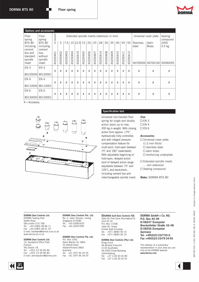
Options and accessories
DORMA GmbH + Co. KGP.O. Box 40 09D-58247 EnnepetalBreckerfelder Straße 42-48D-58256 EnnepetalGermanyTel. +49(0)23 33/793-0Fax +49(0)23 33/79 34 95
The address of a subsidiary/representation in your area you canfind at the DORMA website:www.dorma.com
Floor Floor Extended spindle inserts (extension in mm) Universal cover plate Sealingspring spring compoundBTS 80 BTS 80 0 5 7,5 10 12,5 15 20 25 28 30 35 40 45 50 Stainless Satin 2300including including steel Brass 0.5 kgcement cementbox and box,standard withoutspindle spindleinsert insert 46700000 46700100 45090059
EN 3 EN 3# # # # # # # # # # # # # # # # #
80120000 80120001
EN 4 EN 4# # # # # # # # # # # # # # # # #
80110000 80110001
EN 6 EN 6# # # # # # # # # # # # # # # # #
80130000 80130001
45
20
04
01
45
20
04
02
45
20
04
03
45
20
04
04
45
20
04
19
45
20
04
05
45
20
04
06
45
20
04
07
45
20
04
14
45
20
04
08
45
20
04
09
45
20
04
10
45
20
04
11
45
20
04
12
# = Accessory
(sta
ndar
d)
DORMA Door Controls Pte. Ltd.No. 2, Jalan Terusan, JurongSingapore 619285Tel. +65 62687633Fax +65 62657995
DORMA Door Controls Pty. Ltd.P.O. Box 1092Narre Warren Vic 380552 Abbott RoadHallam/Victoria 3803AustraliaTel. +61 3/97 96 35 55Fax +61 3/97 96 39 55
DORMA Door Controls Ltd.DORMA Trading ParkStaffa RoadGB-London E10 7QXTel. +44 208/5 58 84 11Fax +44 208/5 58 61 22E-mail: hardware@dorma a-uk.co.ukwww.dorma-uk.co.uk
DORMA Door Controls Ltd.19, Sandyford Office ParkFoxrockIRL-Dublin 18Tel. +353 1/2 95 82 80Fax +353 1/2 95 85 84E-mail: [email protected]
DDORMA Gulf Door Controls FZEJebel Ali Free Zone, Roundabout 8,Unit VC 02P.O. Box 17268Jebel Ali, Dubai United Arab EmiratesTel. +971 48/83 90 14Fax +971 48/83 90 15
DORMA Door Controls (Pty.) Ltd.Kings Court4A Mineral Crescent2135 SouthdaleZA-2000 Crown/GautengJohannesburgTel. +27 11/8 30 02 80Fax +27 11/8 30 02 91
Dd
A R
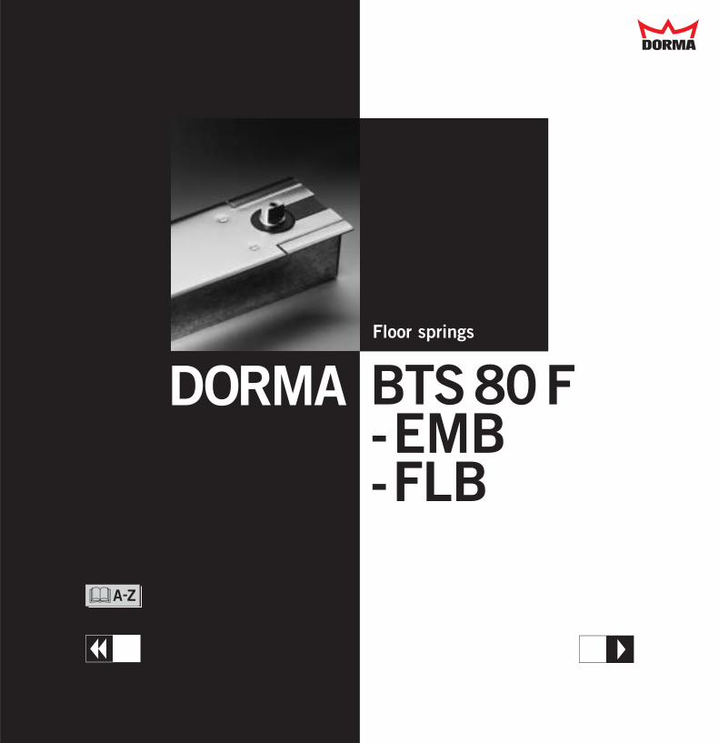
Floor springs
BTS80F-EMB-FLB
DORMA
Dd
T
&
W

78 341
51–57
60
36–4
236
–4278
2
1 3 4
DORMABTS 80 F - EMB - FLB
Floor springs
CERTIFIRE approved for useon certain fire doors:See certificate no. 128(BTS 80 F and EMB).Complies with requirementsof HTM 59 (DOH).PSA approved (MOB H3 03).
Closing force Size EN EN EN EN EN EN EN EN EN4 5 6 4 5 6 4 5 6
Standard doors up to 1100 mm 2 – – 2 – – 2 – –
1250 mm – 2 – – 2 – – 2 –1400 mm – – 2 – – 2 – – 2
Universal model forRH (ISO 5) LH (ISO 6)and double action doors(to close from 175)up to 0905 mm 2 – – 2 – – – – –
1125 mm – 2 – – 2 – – – –1280 mm – – 2 – – 2 – – –
Handed model (to close from 180) LH 2 2 2 2 2 2 2 2 2
Ausführung RH 2 2 2 2 2 2 2 2 2
Closing speed variableby valve adjustment 2 2 2 2 2 2 2 2 2
Latching action variableby valve adjustment 2 2 2 2 2 2 – – –Backcheck, mechanical 2 2 2 2 2 2 – – –Delayed action – – – – – – – – –Hold-open,electro-magnetic,Hold-open pointselectable between75 and 180° – – – 2 2 2 – – –Free swing 0–180° – – – – – – 2 2 2
Weight in kg 7.1 7.1 7.1 7.7 7.7 7.7 7.7 7.7 7.7Dimensions in mm
Length 341 341 341 341 341 341 341 341 341Overall depth 178 178 178 178 178 178 178 178 178Height 160 160 160 160 160 160 160 160 160
Power input in W – – – 2.3 2.3 2.3 2.3 2.3 2.3Operating voltage invDC ± 15 %, residualripple max. 30 % – – – 124 124 124 124 124 124Duty factor in % [Rated for continuous service(duty factor 100%)] – – – 100 100 100 100 100 100Door closer tested to EN 1154 2 2 2 2 2 2 2 2 2
Hold-open devicestested to EN 1155 – – – 2 2 2 2 2 2
2 Yes – No " Option
Technical data BTS 80 F BTS 80 EMB BTS 80 FLBFloor springs designed especiallyfor fire and smoke doors.Wide range of functions, qualityassured.
Quality assured manufactureto DIN ISO 9001,to EN 29001,to BS 5750.Certified and verified byBSI Quality AssuranceReg.-No. Q 6423, FM 10756
For the trade2 Complete range for every
application.2 Simple stock-holdig thanks
to identical accessoriesbeing used throughout theDORMA BTS range.
For the installer2 Easy to install.2 Interchangeable spindle
inserts, available to suitsite conditions.
2 For doors up to 300 kgin weight.
For the architect/specifier2 Concealed installation.2 Range of functions to suit
all applications.
2 Proven, robust unit –for doors weighing up to300 kg.
2 All models tested andquality assured, andapproved by the Institutefor Building Technology,Berlin. For CERTIFIREapprovals see certificateno. 128 (BTS 80 F, EMB).
For the user2 Reliable and fail safe.2 Closing speed unaffected
by changes in temperature.2 Easy door operation
thanks to high mechanicalefficiency.
Plus points
1 Closing speed adjustmentvalve
2 Latching speed adjustmentvalve (not available with theBTS 80 FLB)
3 Plug connector with cable forEMB and FLB power supply
4 Gland for protective conduit(power supply to EMB/FLB)
CERTIFIRE Cert. no. 128
Dd
A E

78
341
358
51–57
60
10558
78
341
358
51–57
60
10558
DORMA BTS 80 F DORMA BTS 80 EMB
Fire door applicationsPlease see the CERTIFIRERegister of ApprovedProducts for full details offire door types with whichthis floor spring may be used.
Approval and certificationThe DORMA BTS 80 F has been approved, and issubject to third-party verification, by the StateMaterial Testing Agency(MPA) of North RhineWestphalia/Dortmund,Germany. PSA approved(MOB H3 03) HTM 59 (DOH).
Fire door applicationsPlease see the CERTIFIRERegister of ApprovedProducts for full details offire door types with whichthis floor spring may be used.
Approval certificationThe DORMA BTS 80 EMBhas been approved by theInstitute for BuildingTechnology, Berlin, for usein combination with all common smoke detectorsystems, e.g. DORMABTS 80 EMB with DORMARMZ 2: approval certificate Z-6.5-1310. PSA approved(MOB H3 03) HTM 59 (DOH).
1 Fully controlled closingwith adjustable speed
2 Adjustable latching action3 Mechanical backcheck
Example shows LH door;mirrored arrangementapplies to RH door.
CERTIFIRE approved cert. no. 128 Floor spring with electromagnetic hold-open CERTIFIREapproved cert. no. 128
2
11
3
1 Fully controlled closingwith adjustable speed
2 Adjustable latching action3 Mechanical backcheck3 Hold-open range
(fall back approx. 3°)
Example shows LH door;mirrored arrangementapplies to RH door.
2
1
4
3
Dd
A E
DORMABTS 80 F - EMB - FLB
Floor springs
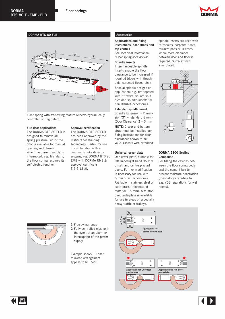
78
341
358
51–57
60
10558
DORMA BTS 80 FLB Accessories
Fire door applicationsThe DORMA BTS 80 FLB isdesigned to remove allspring pressure, whilst thedoor is available for manualopening and closing.When the current supply isinterrupted, e.g. fire alarm,the floor spring resumes itsself-closing function.
Approval certificationThe DORMA BTS 80 FLBhas been approved by theInstitute for BuildingTechnology, Berlin, for usein combination with all common smoke detectorsystems, e.g. DORMA BTS 80EMB with DORMA RMZ 2:approval certificateZ-6.5-1310.
Floor spring with free-swing feature (electro-hydraulicallycontrolled spring detent)
Applications and fixinginstructions, door straps andtop centresSee Technical Information“Floor spring accessories”.
Spindle insertsInterchangeable spindle inserts enable the floor clearance to be increased ifrequired (doors with thresh-olds, carpeted floors, etc.).
Special spindle designs onapplication: e.g. flat taperedwith 3° offset, square spin-dles and spindle inserts fornon DORMA accessories.
Extended spindle insertSpindle Extension = Dimen-sion “X” – (standard 8 mm)(Door Clearance) Z – 3 mm
NOTE: Closer and bottomstrap must be installed perfixing instructions for doorclearances shown to bevalid. Closers with extended
1 Free-swing range2 Fully controlled closing in
the event of an alarm orinterruption of the powersupply
Example shows LH door;mirrored arrangementapplies to RH door.
2
1
Universal cover plateOne cover plate, suitable forleft hand/right hand 36 mmoffset, and centre pivoteddoors. Further modificationis necessary for use with 5 mm offset accessories.Available in stainless steel orsatin brass (thickness ofmaterial 1.5 mm). A reinfor-cing underplate is availablefor use in areas of especiallyheavy traffic or trolleys.
DORMA 2300 SealingCompoundFor filling the cavities bet-ween the floor spring bodyand the cement box to prevent moisture penetration(mandatory according to e.g. VOB regulations for wetrooms).
X Z
8
Z
3
l 25
358
58
79
3535
105
Application for centre pivoted door
Application for LH offsetpivoted door
Application for RH offsetpivoted door
spindle inserts are used withthresholds, carpeted floors,terrazzo pans or in caseswhere more clearance between door and floor isrequired. Surface finsh:Zinc plated.
Dd
A E
DORMABTS 80 F - EMB - FLB
Floor springs
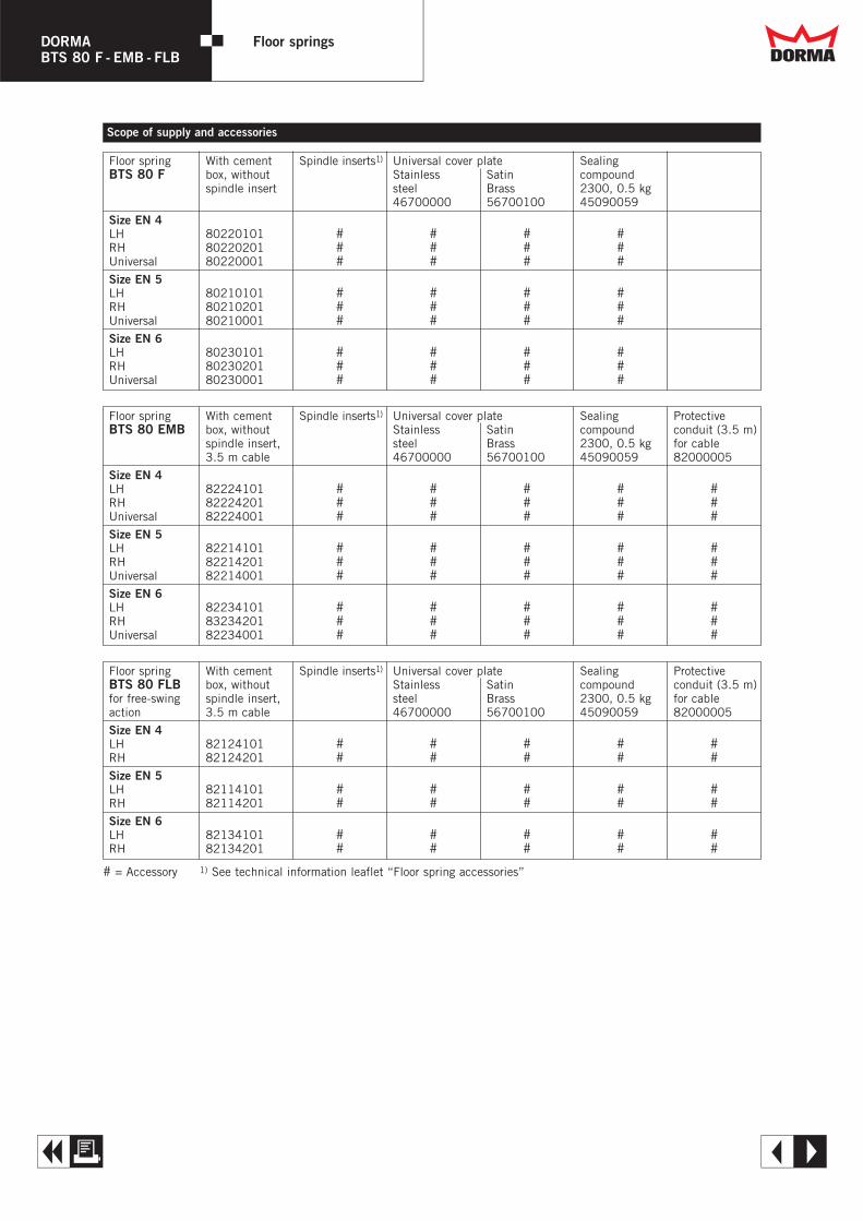
DORMABTS 80 F - EMB - FLB
Floor springs
Floor spring With cement Spindle inserts1) Universal cover plate SealingBTS 80 F box, without Stainless Satin compound
spindle insert steel Brass 2300, 0.5 kg46700000 56700100 45090059
Size EN 4LH 80220101 # # # #RH 80220201 # # # #Universal 80220001 # # # #Size EN 5LH 80210101 # # # #RH 80210201 # # # #Universal 80210001 # # # #Size EN 6LH 80230101 # # # #RH 80230201 # # # #Universal 80230001 # # # #
Scope of supply and accessories
Floor spring With cement Spindle inserts1) Universal cover plate Sealing ProtectiveBTS 80 EMB box, without Stainless Satin compound conduit (3.5 m)
spindle insert, steel Brass 2300, 0.5 kg for cable3.5 m cable 46700000 56700100 45090059 82000005
Size EN 4LH 82224101 # # # # #RH 82224201 # # # # #Universal 82224001 # # # # #Size EN 5LH 82214101 # # # # #RH 82214201 # # # # #Universal 82214001 # # # # #Size EN 6LH 82234101 # # # # #RH 83234201 # # # # #Universal 82234001 # # # # #
# = Accessory 1) See technical information leaflet “Floor spring accessories”
Floor spring With cement Spindle inserts1) Universal cover plate Sealing ProtectiveBTS 80 FLB box, without Stainless Satin compound conduit (3.5 m)for free-swing spindle insert, steel Brass 2300, 0.5 kg for cableaction 3.5 m cable 46700000 56700100 45090059 82000005
Size EN 4LH 82124101 # # # # #RH 82124201 # # # # #Size EN 5LH 82114101 # # # # #RH 82114201 # # # # #Size EN 6LH 82134101 # # # # #RH 82134201 # # # # #
Dd
A E
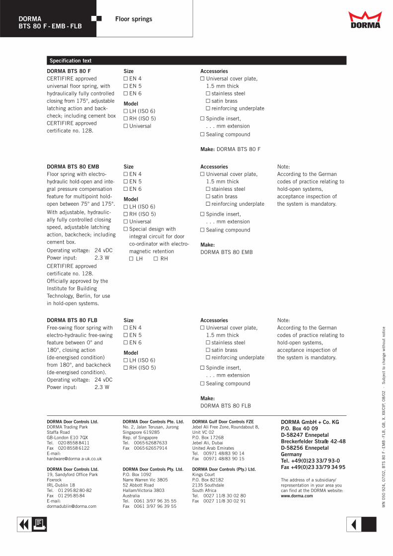
DORMABTS 80 F - EMB - FLB
Floor springs
WN
05
0 9
24
, 0
7/0
2,
BTS
80
F-E
MB
-FLB
, G
B,
X. X
X/C
tP,
08
/02
·
Sub
ject
to
chan
ge w
itho
ut n
otic
e
DORMA BTS 80 FCERTIFIRE approved universal floor spring, withhydraulically fully controlledclosing from 175°, adjustablelatching action and back-check; including cement boxCERTIFIRE approved certificate no. 128.
SizeY EN 4Y EN 5Y EN 6
ModelY LH (ISO 6)Y RH (ISO 5)Y Universal
AccessoriesY Universal cover plate,
1.5 mm thickY stainless steelY satin brassY reinforcing underplate
Y Spindle insert,. . . mm extension
Y Sealing compound
Make: DORMA BTS 80 F
DORMA BTS 80 EMBFloor spring with electro-hydraulic hold-open and inte-gral pressure compensationfeature for multipoint hold-open between 75° and 175°.
With adjustable, hydraulic-ally fully controlled closingspeed, adjustable latchingaction, backcheck; includingcement box.
Operating voltage: 24 vDCPower input: 2.3 W
CERTIFIRE approvedcertificate no. 128.Officially approved by theInstitute for BuildingTechnology, Berlin, for usein hold-open systems.
SizeY EN 4Y EN 5Y EN 6
ModelY LH (ISO 6)Y RH (ISO 5)Y UniversalY Special design with
integral circuit for doorco-ordinator with electro-magnetic retentionY LH Y RH
AccessoriesY Universal cover plate,
1.5 mm thickY stainless steelY satin brassY reinforcing underplate
Y Spindle insert,. . . mm extension
Y Sealing compound
Make:DORMA BTS 80 EMB
Note:According to the Germancodes of practice relating tohold-open systems,acceptance inspection ofthe system is mandatory.
DORMA BTS 80 FLBFree-swing floor spring withelectro-hydraulic free-swingfeature between 0° and180°, closing action(de-energised condition)from 180°, and backcheck(de-energised condition).Operating voltage: 24 vDCPower input: 2.3 W
SizeY EN 4Y EN 5Y EN 6
ModelY LH (ISO 6)Y RH (ISO 5)
AccessoriesY Universal cover plate,
1.5 mm thickY stainless steelY satin brassY reinforcing underplate
Y Spindle insert,. . . mm extension
Y Sealing compound
Make:DORMA BTS 80 FLB
Note:According to the Germancodes of practice relating tohold-open systems,acceptance inspection ofthe system is mandatory.
Specification text
DORMA GmbH + Co. KGP.O. Box 40 09D-58247 EnnepetalBreckerfelder Straße 42-48D-58256 EnnepetalGermanyTel. +49(0)23 33/793-0Fax +49(0)23 33/79 34 95
The address of a subsidiary/representation in your area youcan find at the DORMA website:www.dorma.com
DORMA Gulf Door Controls FZEJebel Ali Free Zone, Roundabout 8,Unit VC 02P.O. Box 17268Jebel Ali, Dubai United Arab EmiratesTel. 00971 48/83 90 14Fax 00971 48/83 90 15
DORMA Door Controls (Pty.) Ltd.Kings CourtP.O. Box 821822135 SouthdaleSouth AfricaTel. 0027 11/8 30 02 80Fax 0027 11/8 30 02 91
DORMA Door Controls Ltd.DORMA Trading ParkStaffa RoadGB-London E10 7QXTel. 020 8558 8411Fax 020 8558 6122E-mail:hardware@dorma a-uk.co.uk
DORMA Door Controls Ltd.19, Sandyford Office ParkFoxrockIRL-Dublin 18Tel. 01 295 82 80-82Fax 01 295 85 84E-mail:[email protected]
DORMA Door Controls Pte. Ltd.No. 2, Jalan Terusan, JurongSingapore 619285Rep. of SingaporeTel. 0065 62687633Fax 0065 62657914
DORMA Door Controls Pty. Ltd.P.O. Box 1092Narre Warren Vic 380552 Abbott RoadHallam/Victoria 3803AustraliaTel. 0061 3/97 96 35 55Fax 0061 3/97 96 39 55
Dd
A R
Floor spring
BTS75 VDORMA
T
&
W
Dd

DORMA BTS 75 V Floor spring
Closing force variable EN(Closing moment approx. 10 – 30 Nm) 1 – 4General doors1) ≤ 1100 mm 2
External doors1) ≤ 1000 mm 2
Non-handed unit suitable for bothsingle action and double action doors 2
Closing force variable by adjusting screw 2
Closing speeds variable by two independent valves 175° – 15° 2
15° – 0°Mechanical backcheck 2
Fixed-position hold open 090° §
at a door angle of 105° §
Cover plate fixing on cement box –on spring body 2
Weight in kg, approx. 3,0Dimensions of cement box Length 285in mm Width 082
Height 050Door closer tested to EN 1154 2
2 Yes – No " Option
1) For applications involving particularly high or heavy doors, and doors which have to close against wind or draught conditions,the next larger closer size or the DORMA BTS 80 should be selected.
Data and features BTS 75 VThe adjustable floor spring –universal in application with aunique combination of functions
... for the trade2 Reduced storage space
requirement and lowerinventories thanks toseparate, interchangeablespindle inserts.
2 Reduced handling weightdue to aluminium body.
... for the installer2 Non-handed unit univer-
sally suitable for bothsingle and double actiondoors.
2 Easy adaptability to indivi-dual requirements thanksto adjustable closing forceand two independentlyadjustable closing speedvalves.
2 Large adjustability withinthe cement box with independent fixing of thecover plate.
... for the architect/specifier2 Concealed installation for
elegant invisibility.2 All main functions
incorporated.2 Rugged construction for
doors up to 120 kg.2 Closing action effective
from 175°.
... for the user2 Consistent closing cycle
virtually unaffected bychanges in temperature.
2 Easy door operationthanks to high mechanicalefficiency
2 Optional integrated fixed-position hold open.
2 High corrosion resistancethanks to aluminium body.
Plus points ...
Whether it be standard, narrow or wide, LH or RHsingle action, or a doubleaction door – the newDORMA BTS 75 V is theanswer, offering the idealspring size by simple in-situadjustment of a screw.Designed and built for rugged durability, the DORMABTS 75 V is suitable for alldoors up to a weight of
120 kg and widths up to1100 mm, while its range offunctions ensures maximumuser convenience, comfortand safety.
Quality-assured manufactureto ISO 9001,
EN 29001,BS 5750.
Certified and verified by BSI Quality AssuranceReg. No. Q 6423, FM 10756
3
2
1
1 Adjusting screw for settingthe spring size.
2 Valve for closing speedadjustment 175°–15°.
3 Valve for closing speedadjustment 15°–0°.
Range of spindeles of suit each application
Dd
A E
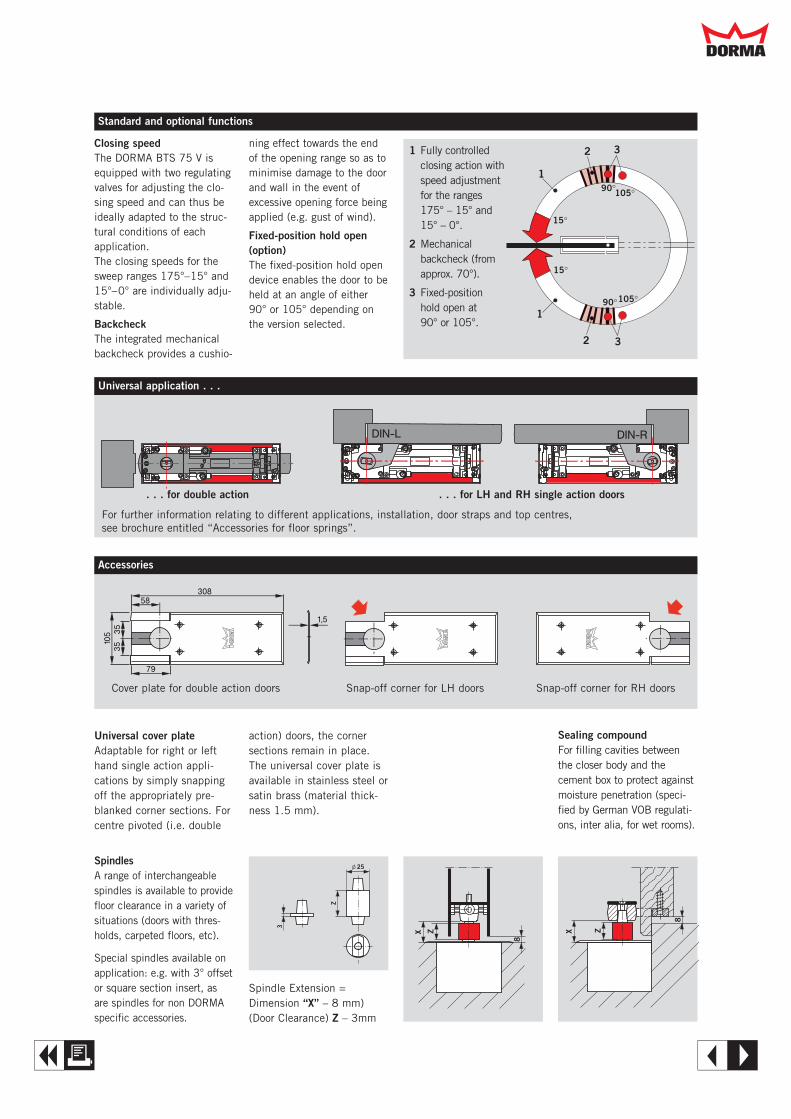
32
2 3
1
1
15°
90°105°
15°
90°105°
Closing speedThe DORMA BTS 75 V isequipped with two regulatingvalves for adjusting the clo-sing speed and can thus beideally adapted to the struc-tural conditions of eachapplication.The closing speeds for thesweep ranges 175°–15° and15°–0° are individually adju-stable.
BackcheckThe integrated mechanicalbackcheck provides a cushio-
ning effect towards the endof the opening range so as tominimise damage to the doorand wall in the event ofexcessive opening force beingapplied (e.g. gust of wind).
Fixed-position hold open(option)The fixed-position hold opendevice enables the door to beheld at an angle of either90° or 105° depending onthe version selected.
1 Fully controlledclosing action withspeed adjustmentfor the ranges 175° – 15° and 15° – 0°.
2 Mechanicalbackcheck (fromapprox. 70°).
3 Fixed-position hold open at 90° or 105°.
X Z
8
X Z
8
Z
3
l 25SpindlesA range of interchangeablespindles is available to providefloor clearance in a variety ofsituations (doors with thres-holds, carpeted floors, etc).
Special spindles available onapplication: e.g. with 3° offsetor square section insert, asare spindles for non DORMAspecific accessories.
Sealing compoundFor filling cavities betweenthe closer body and thecement box to protect againstmoisture penetration (speci-fied by German VOB regulati-ons, inter alia, for wet rooms).
Standard and optional functions
Universal cover plateAdaptable for right or lefthand single action appli-cations by simply snappingoff the appropriately pre-blanked corner sections. Forcentre pivoted (i.e. double
action) doors, the cornersections remain in place.The universal cover plate isavailable in stainless steel orsatin brass (material thick-ness 1.5 mm).
Universal application . . .
. . . for double action . . . for LH and RH single action doors
For further information relating to different applications, installation, door straps and top centres,see brochure entitled “Accessories for floor springs”.
Accessories
Cover plate for double action doors Snap-off corner for LH doors Snap-off corner for RH doors
Spindle Extension =Dimension “X” – 8 mm)(Door Clearance) Z – 3mm
Dd
A E
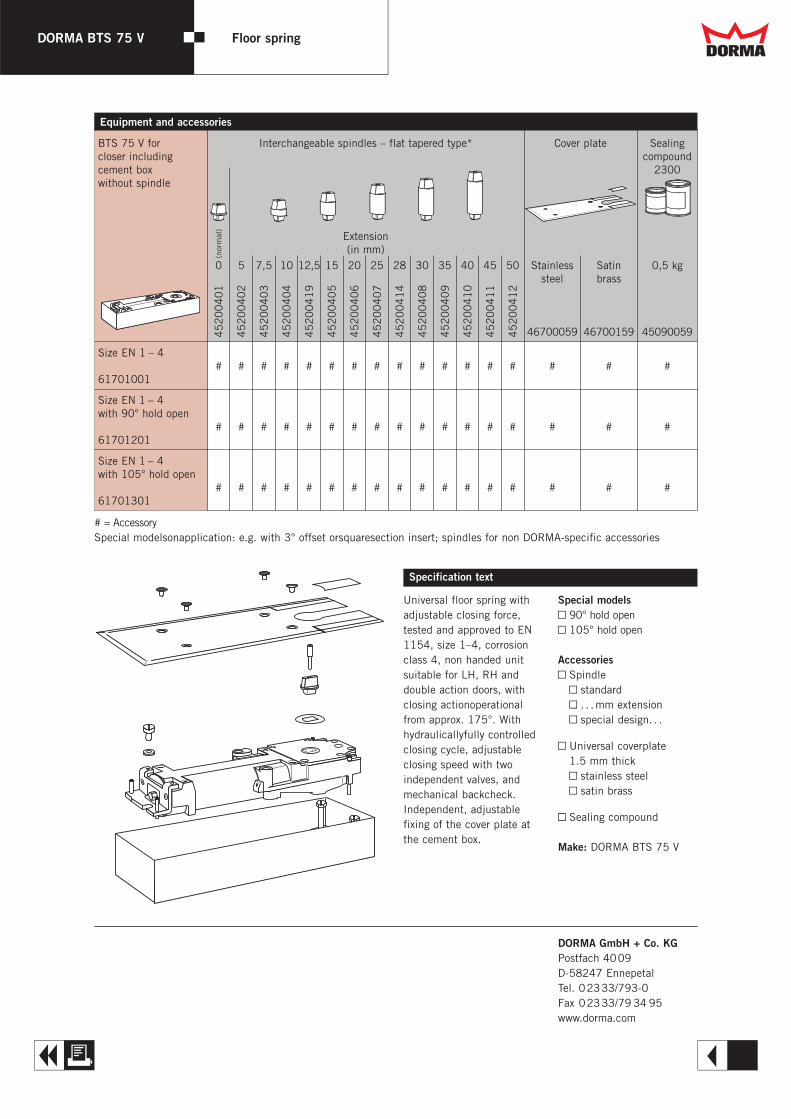
DORMA BTS 75 V Floor spring
Specification text
Universal floor spring withadjustable closing force,tested and approved to EN1154, size 1–4, corrosionclass 4, non handed unitsuitable for LH, RH anddouble action doors, withclosing actionoperationalfrom approx. 175°. Withhydraulicallyfully controlledclosing cycle, adjustable closing speed with two independent valves, andmechanical backcheck.Independent, adjustablefixing of the cover plate atthe cement box.
Special modelsY 90° hold openY 105° hold open
AccessoriesY Spindle
Y standardY . . .mm extensionY special design. . .
Y Universal coverplate1.5 mm thickY stainless steelY satin brass
Y Sealing compound
Make: DORMA BTS 75 V
Equipment and accessories
DORMA GmbH + Co. KGPostfach 4009D-58247 EnnepetalTel. 02333/793-0Fax 02333/79 34 95www.dorma.com
BTS 75 V for Interchangeable spindles – flat tapered type* Cover plate Sealingcloser including compoundcement box 2300without spindle
Extension(in mm)
0 5 7,5 10 12,5 15 20 25 28 30 35 40 45 50 Stainless Satin 0,5 kgsteel brass
46700059 46700159 45090059
Size EN 1 – 4# # # # # # # # # # # # # # # # #
61701001
Size EN 1 – 4with 90° hold open
# # # # # # # # # # # # # # # # #61701201
Size EN 1 – 4with 105° hold open
# # # # # # # # # # # # # # # # #61701301
45
20
04
01
45
20
04
02
45
20
04
03
45
20
04
04
45
20
04
19
45
20
04
05
45
20
04
06
45
20
04
07
45
20
04
14
45
20
04
08
45
20
04
09
45
20
04
10
45
20
04
11
45
20
04
12
# = Accessory Special modelsonapplication: e.g. with 3° offset orsquaresection insert; spindles for non DORMA-specific accessories
(nor
mal
)
Dd
A R

DORMA BTS 65Fórmula para ladeterminación de lafuerza de cierre Dd
Q
Cálculo del momento de cierre, que es necesario parapoder superar una presión del aire específica.
Medida del cierrapuertas según tabla: EN 4 (= 26 Nm)
MtTS = P · A · b2
MtTS = Momento de cierre mínimo del cierrapuertas [Nm]
P = Presión del aire [N/m2] (Pascal)A = Superficie de puerta [m2]b = Ancho de puerta [m]
Ejemplo: Ancho de puerta = 0,9 mAltura de puerta = 2,05 mPresión del aire = 30 Pa
MtTS = 30 · 0,9 · 2,05 · 0,9 = 24,9 Nm2
&
Medida del Máximo ancho Peso de Momento de cierre mínimo Grado de rendi-cierra- de puerta la puerta en Nm miento del cierra-
puertas recomendado de prueba puertas mínimo
para cadaángulo de en un 2°
EN mm kg 2° 90° abertura %
1 < 750 20 9 3 2 502 < 850 40 13 4 3 503 < 950 60 18 6 4 554 <1100 80 26 9 6 605 <1250 100 37 12 8 656 <1400 120 54 18 11 657 <1600 160 87 29 18 65
Si el peso real y el tamaño de la puerta, en la cual se monta el cierrapuertas, se refiere a dos medi-das de cierrapuertas, debería utilizarse el cierrapuertas de mayor tamaño. Los anchos de la puerta sirven para los montajes estándar. En caso de puertas excepcionalmente altasy pesadas, o en lugares con corriente de aire o mucho viento, o en caso de montajes especialesdeberán ser utilizados cierrapuertas más grandes.
Extracto de la EN 1154
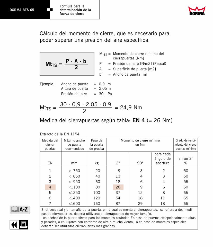
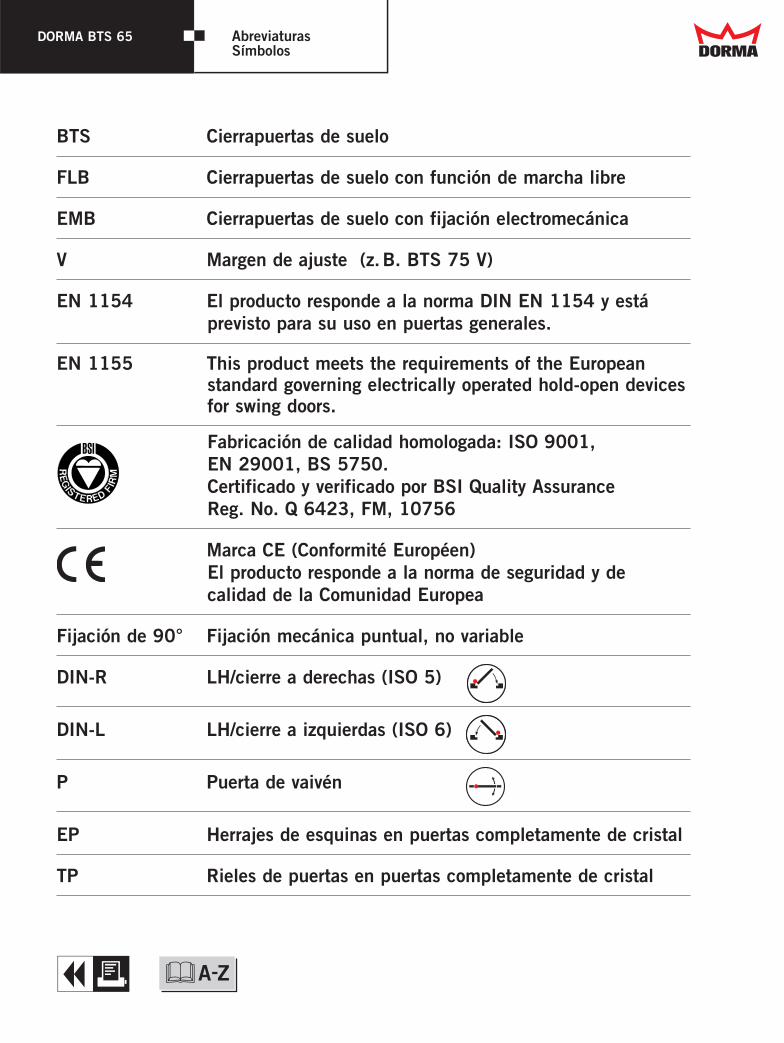
BTS Cierrapuertas de suelo
FLB Cierrapuertas de suelo con función de marcha libre
EMB Cierrapuertas de suelo con fijación electromecánica
V Margen de ajuste (z.B. BTS 75 V)
EN 1154 El producto responde a la norma DIN EN 1154 y está previsto para su uso en puertas generales.
EN 1155 This product meets the requirements of the Europeanstandard governing electrically operated hold-open devicesfor swing doors.
Fabricación de calidad homologada: ISO 9001, EN 29001, BS 5750.Certificado y verificado por BSI Quality Assurance Reg. No. Q 6423, FM, 10756
Marca CE (Conformité Européen)El producto responde a la norma de seguridad y de calidad de la Comunidad Europea
Fijación de 90° Fijación mecánica puntual, no variable
DIN-R LH/cierre a derechas (ISO 5)
DIN-L LH/cierre a izquierdas (ISO 6)
P Puerta de vaivén
EP Herrajes de esquinas en puertas completamente de cristal
TP Rieles de puertas en puertas completamente de cristal
DORMA BTS 65 AbreviaturasSímbolos Dd
Q &
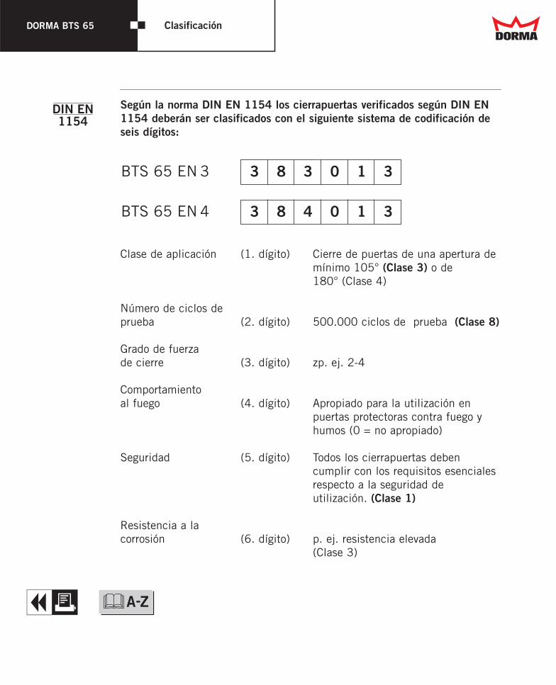
DORMA BTS 65 Clasificación
Según la norma DIN EN 1154 los cierrapuertas verificados según DIN EN1154 deberán ser clasificados con el siguiente sistema de codificación deseis dígitos:
Clase de aplicación (1. dígito) Cierre de puertas de una apertura de mínimo 105° (Clase 3) o de180° (Clase 4)
Número de ciclos deprueba (2. dígito) 500.000 ciclos de prueba (Clase 8)
Grado de fuerzade cierre (3. dígito) zp. ej. 2-4
Comportamientoal fuego (4. dígito) Apropiado para la utilización en
puertas protectoras contra fuego yhumos (0 = no apropiado)
Seguridad (5. dígito) Todos los cierrapuertas deben cumplir con los requisitos esencialesrespecto a la seguridad de utilización. (Clase 1)
Resistencia a la corrosión (6. dígito) p. ej. resistencia elevada
(Clase 3)
3 8 3 0 1 3
3 8 4 0 1 3
DIN EN1154
Dd
Q &
BTS 65 EN 3
BTS 65 EN 4
DORMA BTS 65Cierrapuertas de suelo para puertas de vaivén
/
START STOP
Duración del vídeo: aprox. 2 minutos
Dd
W &A-Z

Dd
T
Su socio a nivel mundial
ü
ü
ü
ü
ü
Info
&
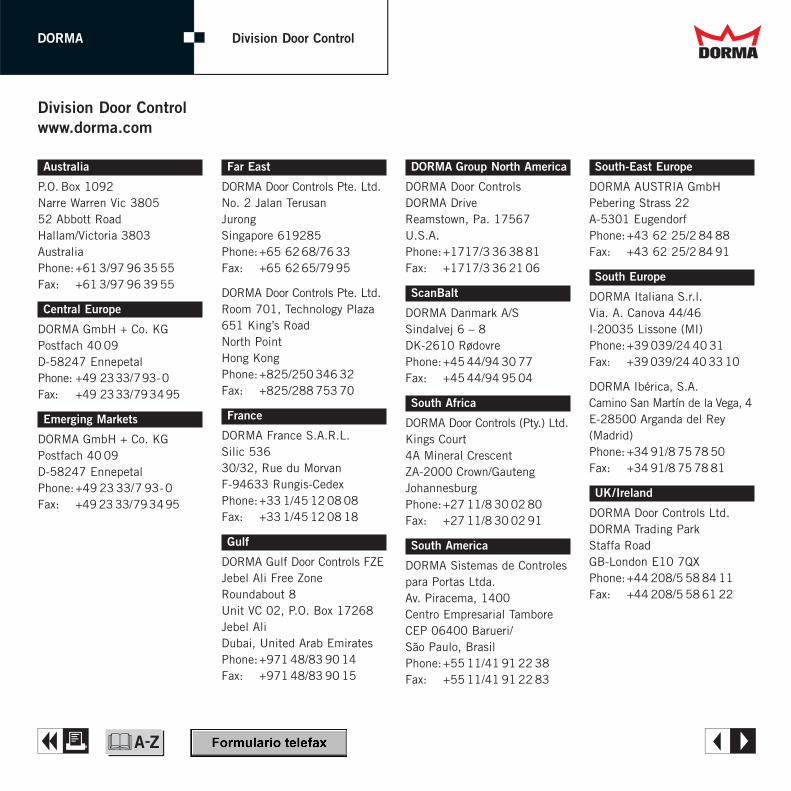
DdDORMA Division Door Control
Australia
P.O. Box 1092Narre Warren Vic 380552 Abbott RoadHallam/Victoria 3803AustraliaPhone:+61 3/97 96 35 55Fax: +61 3/97 96 39 55
Central Europe
DORMA GmbH + Co. KGPostfach 40 09D-58247 EnnepetalPhone: +49 2333/793-0Fax: +49 2333/793495
Emerging Markets
DORMA GmbH + Co. KGPostfach 40 09D-58247 EnnepetalPhone:+49 23 33/7 93-0Fax: +49 23 33/793495
Far East
DORMA Door Controls Pte. Ltd.No. 2 Jalan TerusanJurongSingapore 619285Phone:+65 6268/7633Fax: +65 6265/7995
DORMA Door Controls Pte. Ltd.Room 701, Technology Plaza651 King’s RoadNorth PointHong KongPhone:+825/250 346 32Fax: +825/288 753 70
France
DORMA France S.A.R.L.Silic 53630/32, Rue du MorvanF-94633 Rungis-CedexPhone:+33 1/45 12 08 08Fax: +33 1/45 12 08 18
Gulf
DORMA Gulf Door Controls FZEJebel Ali Free ZoneRoundabout 8Unit VC 02, P.O. Box 17268Jebel AliDubai, United Arab EmiratesPhone:+971 48/83 90 14Fax: +971 48/83 90 15
DORMA Group North America
DORMA Door ControlsDORMA Drive Reamstown, Pa. 17567 U.S.A.Phone:+1717/3 36 38 81Fax: +1717/3 36 21 06
ScanBalt
DORMA Danmark A/SSindalvej 6 – 8DK-2610 RødovrePhone:+45 44/94 30 77Fax: +45 44/94 95 04
South Africa
DORMA Door Controls (Pty.) Ltd.Kings Court4A Mineral CrescentZA-2000 Crown/GautengJohannesburgPhone:+27 11/8 30 02 80Fax: +27 11/8 30 02 91
South America
DORMA Sistemas de Controlespara Portas Ltda.Av. Piracema, 1400Centro Empresarial TamboreCEP 06400 Barueri/São Paulo, BrasilPhone:+55 11/41 91 22 38Fax: +55 11/41 91 22 83
South-East Europe
DORMA AUSTRIA GmbHPebering Strass 22A-5301 EugendorfPhone:+43 62 25/2 84 88Fax: +43 62 25/2 84 91
South Europe
DORMA Italiana S.r.l.Via. A. Canova 44/46I-20035 Lissone (MI)Phone:+39 039/24 40 31Fax: +39 039/24 40 33 10
DORMA Ibérica, S.A.Camino San Martín de la Vega, 4E-28500 Arganda del Rey(Madrid)Phone: +34 91/8 75 78 50Fax: +34 91/8 75 78 81
UK/Ireland
DORMA Door Controls Ltd.DORMA Trading ParkStaffa RoadGB-London E10 7QXPhone:+44 208/5 58 84 11Fax: +44 208/5 58 61 22
Division Door Controlwww.dorma.com
A E&
DdDORMADivision Door Control
HQ
A E&
DORMA GmbH + Co. KGPostfach 40 0958247 EnnepetalBreckerfelder Straße 42–4858256 EnnepetalGermanyTel. +49 (0) 23 33/7 93-0Fax +49 (0) 23 33/7 93-4 95www.dorma.com
Corporate HQ
OGRO Beschlagtechnik GmbHDonnenberger Straße 242553 VelbertGermanyTel. +49 (0) 20 53/4 95-0Fax +49 (0) 20 53/4 95-100www.ogro.de
DORMA Schlosstechnik GmbHRosendahler Straße 3758285 GevelsbergGermanyTel. +49 (0) 23 32/75 89-0Fax +49 (0) 23 32/75 89-16www.dorma.com
DORMA-Glas GmbHPostfach 32 6832076 Bad SalzuflenMax-Planck-Straße 37–4332107 Bad SalzuflenGermanyTel. +49 (0) 52 22/9 24-0Fax +49 (0) 52 22/9 24-146www.dorma-glas.com

DdDORMADivision Door Control
Your Partnersin Europe
A E&
Your Partners in EuropeA – Austria*DORMA AUSTRIA GmbHPebering Strass 22A-5301 EugendorfPhone: +43 62 25/2 84 88Fax: +43 62 25/2 84 91www.dorma.at
A – Austria**DORMA AKSAutomatic GmbHPebering Strass 22A-5301 EugendorfPhone:+43 62 25/86 36-0Fax: +43 62 25/26 59-0
B – BelgiumDORMA foquin N.V.Lieven Bauwensstraat 21aB-8200 BruggePhone: +32 50/45 15 70Fax: +32 50/31 95 05www.dorma.be
BG – BulgariaDORMA BALKAN EOODTehnika za vratistr. Akad. Georgy Bonchev,blok 6BG-1113 SofiaPhone: +359 2/70 39 02Fax: +359 2/70 40 03
CH – Switzerland*DORMA Türtechnik AGRosswiesstrasse 27CH-8608 BubikonPhone: +41 55/2 53 42 60Fax: +41 55/2 53 42 65www.dorma.ch
CH – Switzerland**DORMA Schweiz AGIndustrie HegiCH-9425 ThalPhone:+41 71/8 86 46 46Fax: +41 71/8 86 46 56E-Mail: [email protected]
CZ – Czech RepublicDORMA dverní technika CR,s.r.o.Vinohradská 184CZ-13052 Praha 3Phone: +420 2/67 13 21 78Fax: +420 2/67 13 21 71
DK – DenmarkDORMA Danmark A/SSindalvej 6 – 8DK-2610 RødovrePhone: +45 44/54 30 00Fax: +45 44/94 95 04www.dorma.dkE-Mail: [email protected]
E – SpainDORMA Ibérica, S.A.Camino San Martín de laVega, 4E-28500 Arganda del Rey(Madrid)Phone: +34 91/8 75 78 50Fax: +34 91/8 75 78 81www.dorma.es
EE – EstoniaDORMA RepresentationEstoniaMart Rosin, Lootuse pst. 90EE-11619 TallinnPhone: +37 2/6 70 70 64Fax: +37 2/6 70 70 65
F – France*DORMA France S.A.R.L.Silic 536, 30/32, Rue du MorvanF-94633 Rungis-CedexPhone: +33 1/45 12 08 08Fax: +33 1/45 12 08 18www.dorma.fr
F – France**DORMA Accueil SASZAC de l’EchangeurF-73100 Grésy-sur-AixPhone: +33 4/79 34 89 24Fax: +33 4/79 34 89 23
FIN – FinlandDORMA Finland OyTiilenlyöjänkuja 6FIN-01720 VantaaPhone: +358 9/8 78 91 30Fax: +358 9/8 78 40 67www.dorma.fi
GB – Great Britain/*Northern IrelandDORMA Door Controls Ltd.DORMA Trading ParkStaffa RoadGB-London E10 7QXPhone: +44 208/5 58 84 11Fax: +44 208/5 58 61 22www.dorma-uk.co.uk
GB – Great Britain/**Northern IrelandDORMA Entrance Systems Ltd.Woodside Industrial ParkWorks RoadGB-LetchworthHertfordshire SG6 1LAPhone: +44 14 62/48 05 44Fax: +44 14 62/47 25 01
**Division Door Control**Division Automatic
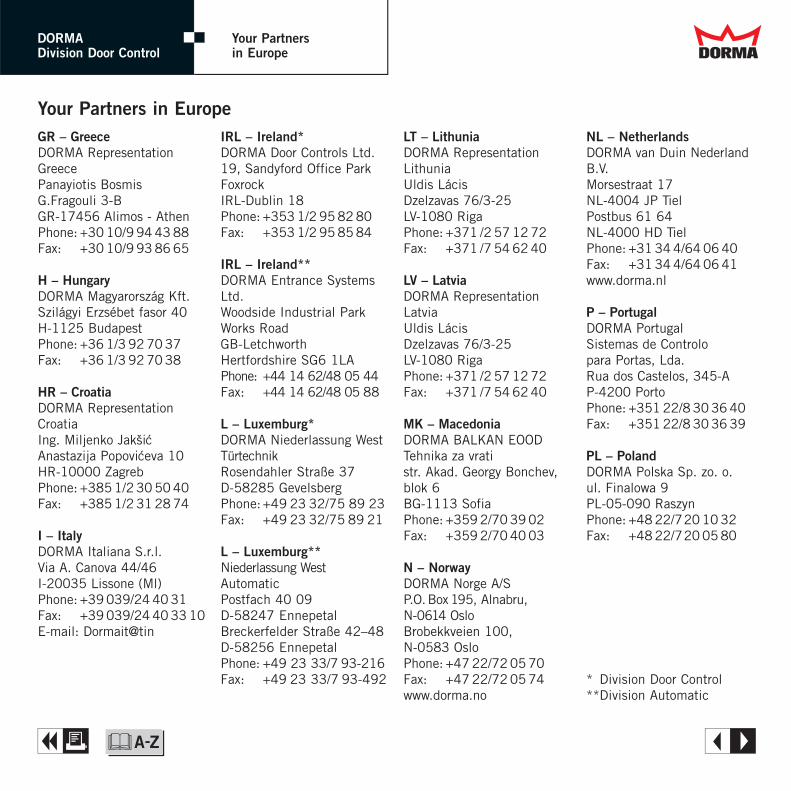
DdDORMADivision Door Control
Your Partnersin Europe
A E&
Your Partners in EuropeGR – GreeceDORMA RepresentationGreecePanayiotis BosmisG.Fragouli 3-BGR-17456 Alimos - AthenPhone: +30 10/9 94 43 88Fax: +30 10/9 93 86 65
H – HungaryDORMA Magyarország Kft.Szilágyi Erzsébet fasor 40H-1125 BudapestPhone: +36 1/3 92 70 37Fax: +36 1/3 92 70 38
HR – CroatiaDORMA RepresentationCroatiaIng. Miljenko JaksicAnastazija Popoviceva 10HR-10000 ZagrebPhone: +385 1/2 30 50 40Fax: +385 1/2 31 28 74
I – ItalyDORMA Italiana S.r.l.Via A. Canova 44/46I-20035 Lissone (Ml)Phone: +39 039/24 40 31Fax: +39 039/24 40 33 10E-mail: Dormait@tin
IRL – Ireland*DORMA Door Controls Ltd.19, Sandyford Office ParkFoxrockIRL-Dublin 18Phone: +353 1/2 95 82 80Fax: +353 1/2 95 85 84
IRL – Ireland**DORMA Entrance SystemsLtd.Woodside Industrial ParkWorks RoadGB-LetchworthHertfordshire SG6 1LAPhone: +44 14 62/48 05 44Fax: +44 14 62/48 05 88
L – Luxemburg*DORMA Niederlassung WestTürtechnikRosendahler Straße 37D-58285 GevelsbergPhone:+49 23 32/75 89 23Fax: +49 23 32/75 89 21
L – Luxemburg**Niederlassung WestAutomaticPostfach 40 09D-58247 EnnepetalBreckerfelder Straße 42–48D-58256 EnnepetalPhone: +49 23 33/7 93-216Fax: +49 23 33/7 93-492
LT – LithuniaDORMA RepresentationLithuniaUldis LácisDzelzavas 76/3-25LV-1080 RigaPhone: +371 /2 57 12 72Fax: +371 /7 54 62 40
LV – LatviaDORMA RepresentationLatviaUldis LácisDzelzavas 76/3-25LV-1080 RigaPhone: +371 /2 57 12 72Fax: +371 /7 54 62 40
MK – MacedoniaDORMA BALKAN EOODTehnika za vratistr. Akad. Georgy Bonchev,blok 6BG-1113 SofiaPhone: +359 2/70 39 02Fax: +359 2/70 40 03
N – NorwayDORMA Norge A/SP.O.Box 195, Alnabru,N-0614 OsloBrobekkveien 100,N-0583 OsloPhone: +47 22/72 05 70Fax: +47 22/72 05 74www.dorma.no
NL – NetherlandsDORMA van Duin NederlandB.V.Morsestraat 17NL-4004 JP TielPostbus 61 64NL-4000 HD TielPhone: +31 34 4/64 06 40Fax: +31 34 4/64 06 41www.dorma.nl
P – PortugalDORMA PortugalSistemas de Controlopara Portas, Lda.Rua dos Castelos, 345-AP-4200 PortoPhone: +351 22/8 30 36 40Fax: +351 22/8 30 36 39
PL – PolandDORMA Polska Sp. zo. o.ul. Finalowa 9PL-05-090 RaszynPhone: +48 22/720 10 32Fax: +48 22/720 05 80
**Division Door Control**Division Automatic
DdDORMADivision Door Control
Your Partnersin Europe
A E&
Your Partners in EuropeRO – RumaniaDORMA RepresentationRumaniaGabriel GavrilescuAleea Bran, Nr. 2, Bl. 92Sc. 1, Ap. 11, Sector 4RO-75158 BukarestPhone: +4021/3 30 05 68Fax: +4021/3 30 05 68
RUS – RussiaDORMA RepresentationMoscowPhone: +7 095/2 58 12 26Fax: +7 095/2 58 12 26
RUS – RussiaDORMA RepresentationSt. PetersburgAlexey GruzdevSvetlanovskij 21, Apt. 35RUS-194223 St. PetersburgPhone: +7 812/5 52 68 46Fax: +7 812/5 52 68 46
S – SwedenDORMA Sverige ABDatavägen 20S-43632 AskimPhone: +46 31/28 95 20Fax: +46 31/28 17 39www.dorma.se
SK – Slovakian RepublicDORMA Slovensko spol.s.r.o.Ruzová dolina 6SK-82106 BratislavaPhone: +421 2/50 22 12 83Fax: +421 2/50 22 12 86
SLO – SloveniaDORMA RepresentationSlovenia ICL d.o.o.,PE Murska SobotaPlese 9SLO-9000 Murska SobotaPhone: +386 2/5 30 20 10Fax: +386 2/5 30 20 20
TR – TurkeyDORMA Kapi Kontrolleri Ltd.Sti Sahraticedid Mah.Mengu Sok. Basak Apt. 17/6TR-81080 Erenkoy/IstanbulTurkiyePhone: +90 216/3 60 00 56Fax: +90 216/3 60 17 91
UA – UkraineDORMA RepresentationUkraine15 Kominterna Str.UA-252032 KiewPhone: +380 44/2 44 38 97Fax: +380 44/2 44 38 97
YU – Republic YugoslaviaDORMA RepresentationRepublic YugoslaviaELMATMaksima Gorkog 135YU-11000 BelgradePhone: +381 11/4 44 73 21Fax: +381 11/4 44 73 21
The address of asubsidiary/representationin your area you can findat the DORMA website:www.dorma.com
DdDORMADivision Door Control
Your PartnersWorldwide
A E&
Your Partners in America, AfricaCanadaDORMA Door Controls1680 Courtney Park DriveUnit 13Mississauga,Ontario L5T 1R4CanadaPhone: +1 905/6 70 12 81Fax: +1 905/6 70 58 50
USA/Caribbean andCentral America
DORMA Group North AmericaDORMA Door ControlsDORMA DriveReamstown, Pa. 17567USAPhone: +1 717/3 36 38 81Fax: +1 717/3 36 21 06(Sales & Production)
DORMA Automatics, Inc.375 Prince George’s Blvd.Upper Marlboro, MD 20774USAPhone: +1 301/3 90 3600Fax: +1 301/3 90 5515
DORMA-Glas Inc.375 Prince George’s Blvd.Upper Marlboro, MD 20774USAPhone: +1 301/3 90 1000Fax: +1 301/3 90 0011(DORMA-Glas only)
MéxicoDORMA MEXICO S DE R.L. DE C.VMonte Albán # 400Col. Narvarte03600, México, D.F.MéxicoPhone: +52 55/55 39-0313 Fax: +52 55/55 39-0769
South AmericaDORMA Sistemas deControlespara Portas Ltda.Av. Piracema, 1400Centro Empresarial TamboreCEP 06400 Barueri Sao PauloBrasilPhone: +55 11/41 91 32 44Fax: +55 11/41 91 21 93
Africa, English SpeakingDORMA GmbH + Co. KGP.O. Box 40 09D-58247 EnnepetalBreckerfelder Straße 42–48D-58256 EnnepetalGermanyPhone: +4923 33/7 93-0Fax: +4923 33/793495
Africa, French SpeakingDORMA France S.A.R.L.Silic 53630/32, Rue du MorvanF-94633 Rungis-CedexPhone: +33 1/45 12 08 08Fax: +33 1/45 12 08 18
South AfricaDORMA Door Controls (Pty.)Ltd.Kings Court4A Mineral CrescentZA-2000 Crown/GautengJohannesburgPhone: +27 11/8 30 02 80Fax: +27 11/8 30 02 91
DdDORMADivision Door Control
Your PartnersWorldwide
A R&
Your Partners in Africa, Asia, AustraliaNear East
Cyprus, Israel, Malta,Pakistan
DORMA GmbH + Co. KGP.O. Box 40 09D-58247 EnnepetalBreckerfelder Straße 42–48D-58256 EnnepetalGermanyPhone: +49 23 33/7 93-512Fax: +49 23 33/7 93-533
Middle EastBahrain, Egypt, Jordan,Iran, Iraq, Kuwait,Lebanon, Libya, Oman,Qatar, Saudi Arabia, Syria,UAE, Yemen
DORMA GulfDoor Controls FZEJebel Ali Free Zone,Roundabout 8,Unit VC 02P.O. Box 17268Jebel AliDubaiUnited Arab EmiratesPhone: +971 48/83 90 14Fax: +971 48/83 90 15
DORMA Arabia AutomaticDoors Ltd.P.O. Box 1633Dammam 31441Kingdom of Saudi ArabiaPhone: +966 38/47 23 94Fax: +966 38/47 23 68
Far EastChina, Hong Kong,Indonesia, Japan,Malaysia, Philippines,Singapore, South Korea,Sri Lanka, Taiwan,Thailand, Vietnam
DORMA Door Controls Pte.Ltd.No. 2 Jalan TerusanJurongSingapore 619285Phone: +65 62687633Fax: +65 62657995(Sales)
DORMA Door Controls Pte.Ltd.Room 701, Technology Plaza651 King’s RoadNorth PointHong KongPhone: +825/250 346 32Fax: +825/288 753 70
Far East/SingaporeDORMA ProductionGmbH + Co. KGSingapore BranchNo. 2 Jalan TerusanJurongSingapore 619285Phone: +65 6268/7633Fax: +65 6265/7995(Production)
India/Sri LankaDORMA Door Controls IndiaPvt. Ltd.No. 14, Basement,Pattullous RoadChennai – 600 002IndiaPhone: +91 44/8 58 50 97Fax: +91 44/8 58 50 96
AustraliaNew Zealand and thePacific Islands
DORMA Door Controls Pty.Ltd.P.O. Box 1092Narre Warren Vic 380552 Abbott RoadHallam/Victoria 3803AustraliaPhone: +61 3/97 96 35 55Fax: +61 3/97 96 39 55
BWN Industries (Aust.) Pty.Ltd.46, Abbott RoadHallam/Victoria 3803AustraliaPhone: +61 3/97 96 41 11Fax: +61 3/97 96 37 67
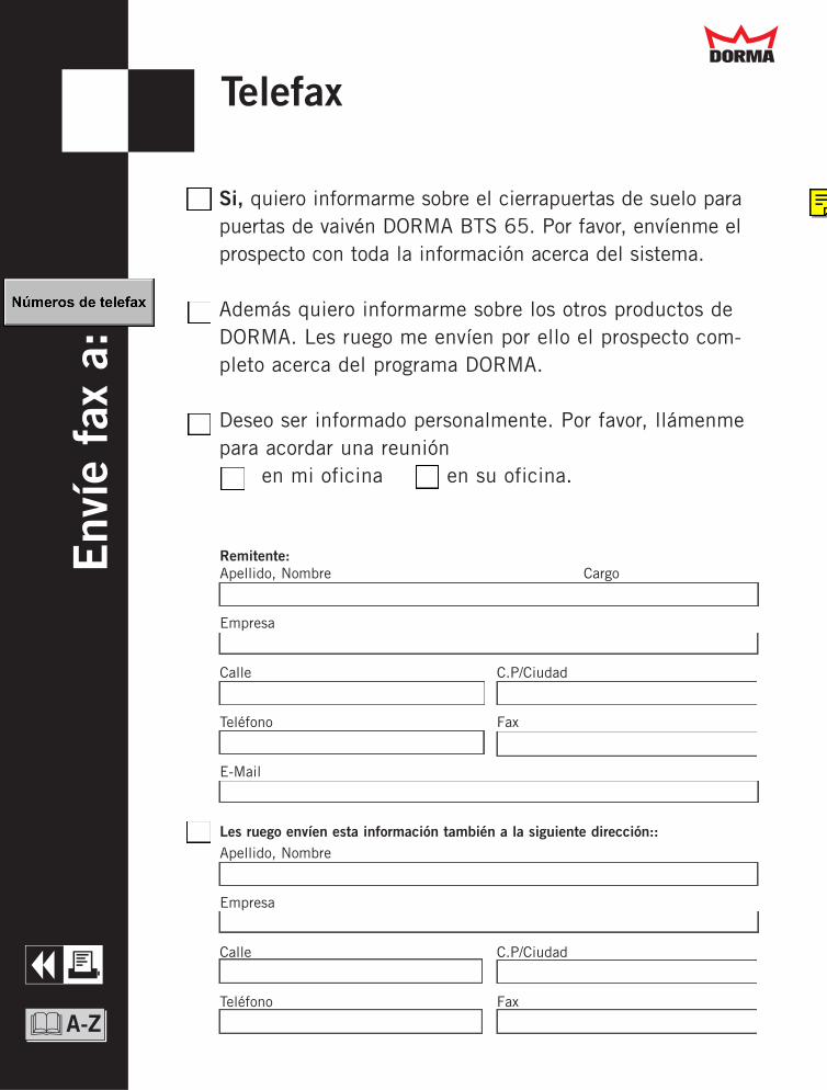
Si, quiero informarme sobre el cierrapuertas de suelo parapuertas de vaivén DORMA BTS 65. Por favor, envíenme elprospecto con toda la información acerca del sistema.
Además quiero informarme sobre los otros productos deDORMA. Les ruego me envíen por ello el prospecto com-pleto acerca del programa DORMA.
Deseo ser informado personalmente. Por favor, llámenmepara acordar una reunión
en mi oficina en su oficina.
TelefaxE
nvíe
fax
a:
Remitente:Apellido, Nombre Cargo
Empresa
Calle C.P/Ciudad
Teléfono Fax
Les ruego envíen esta información también a la siguiente dirección::Apellido, Nombre
Empresa
Calle C.P/Ciudad
Teléfono Fax
&A-Z
Q
Dd
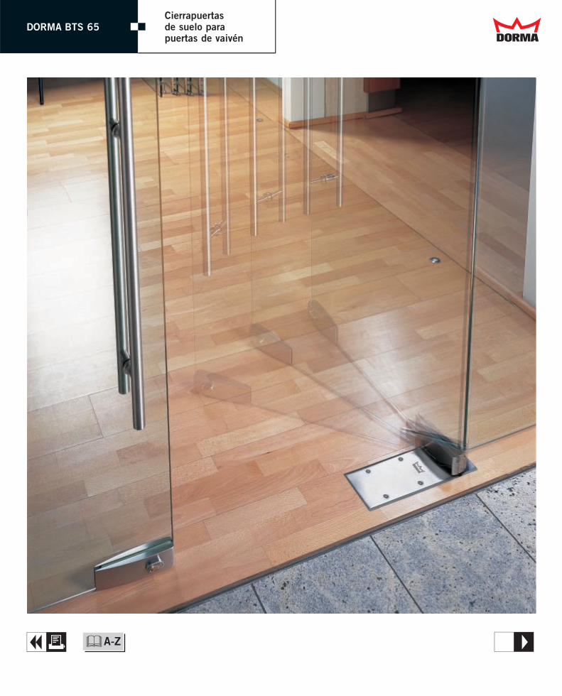
DORMA BTS 65Cierrapuertas de suelo para puertas de vaivén Dd
A &A-Z T
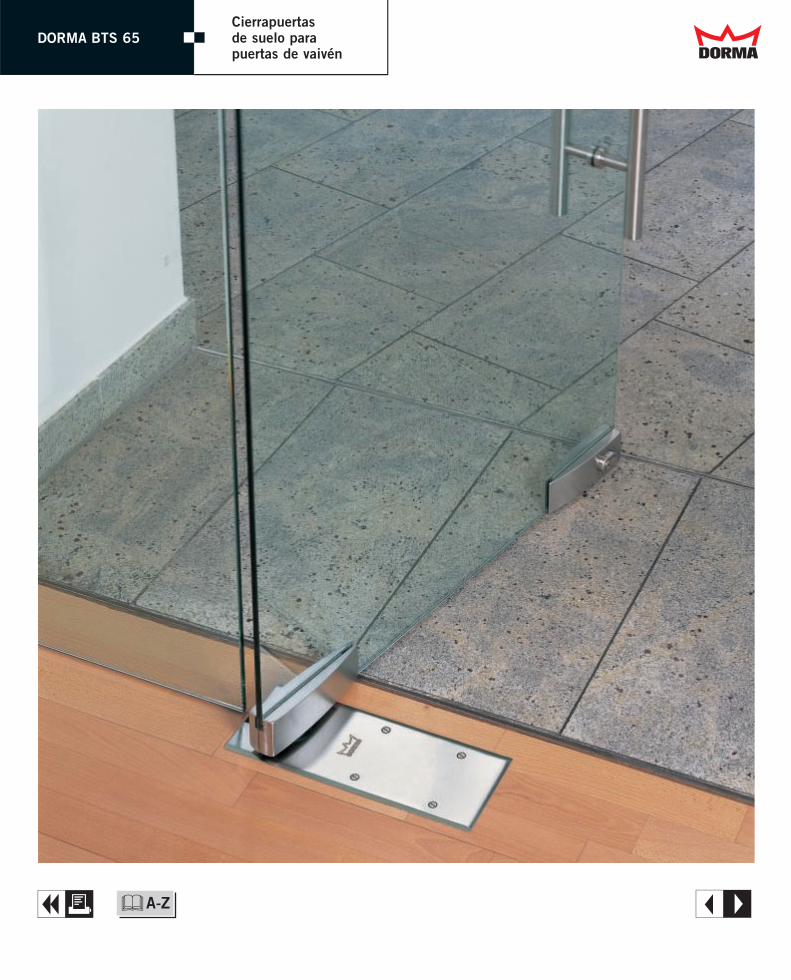
DORMA BTS 65Cierrapuertas de suelo para puertas de vaivén Dd
A &A-Z E
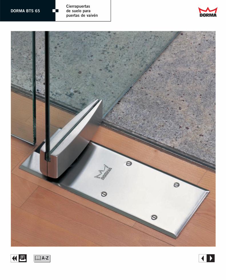
DORMA BTS 65Cierrapuertas de suelo para puertas de vaivén Dd
A &A-Z E
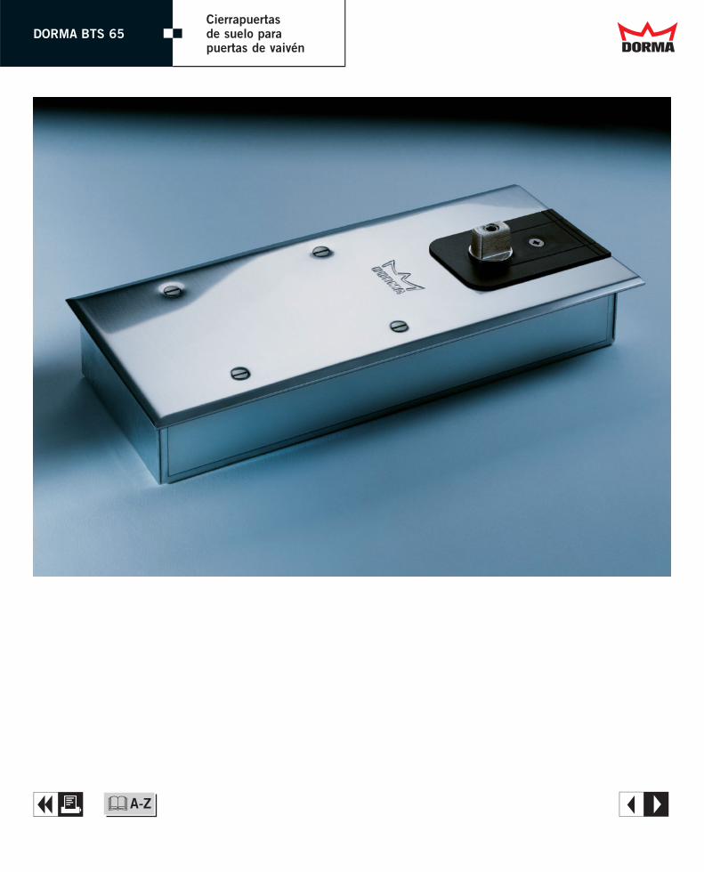
DORMA BTS 65Cierrapuertas de suelo para puertas de vaivén Dd
A &A-Z E

DORMA BTS 65Cierrapuertas de suelo para puertas de vaivén Dd
A &A-Z E
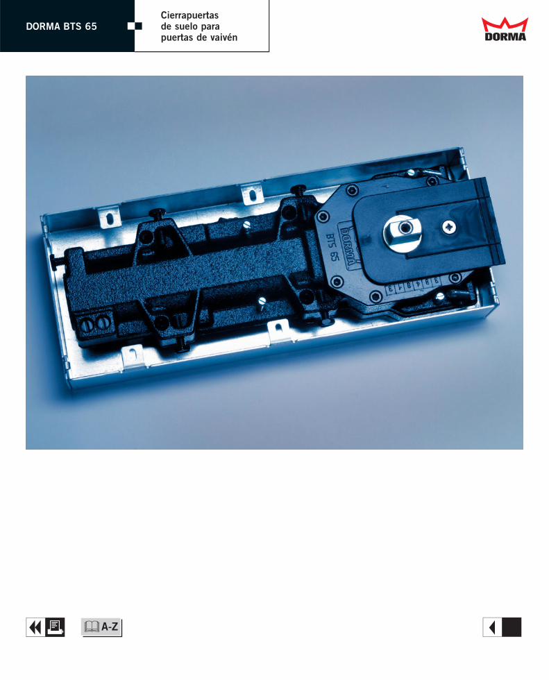
DORMA BTS 65Cierrapuertas de suelo para puertas de vaivén Dd
A &A-Z R
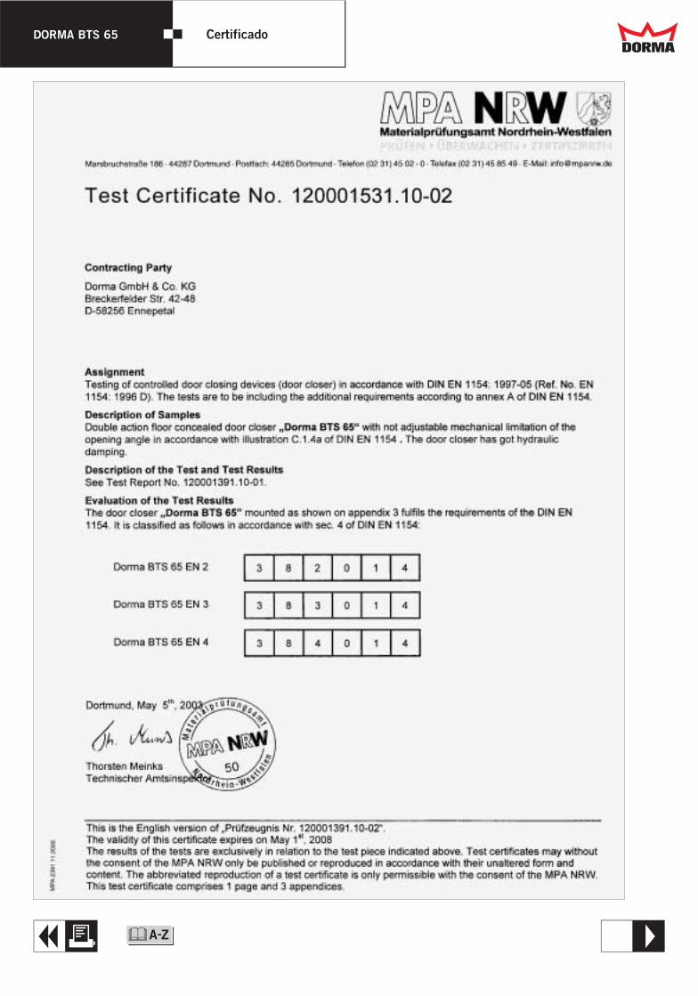
DORMA BTS 65 Certificado Dd
TQ &
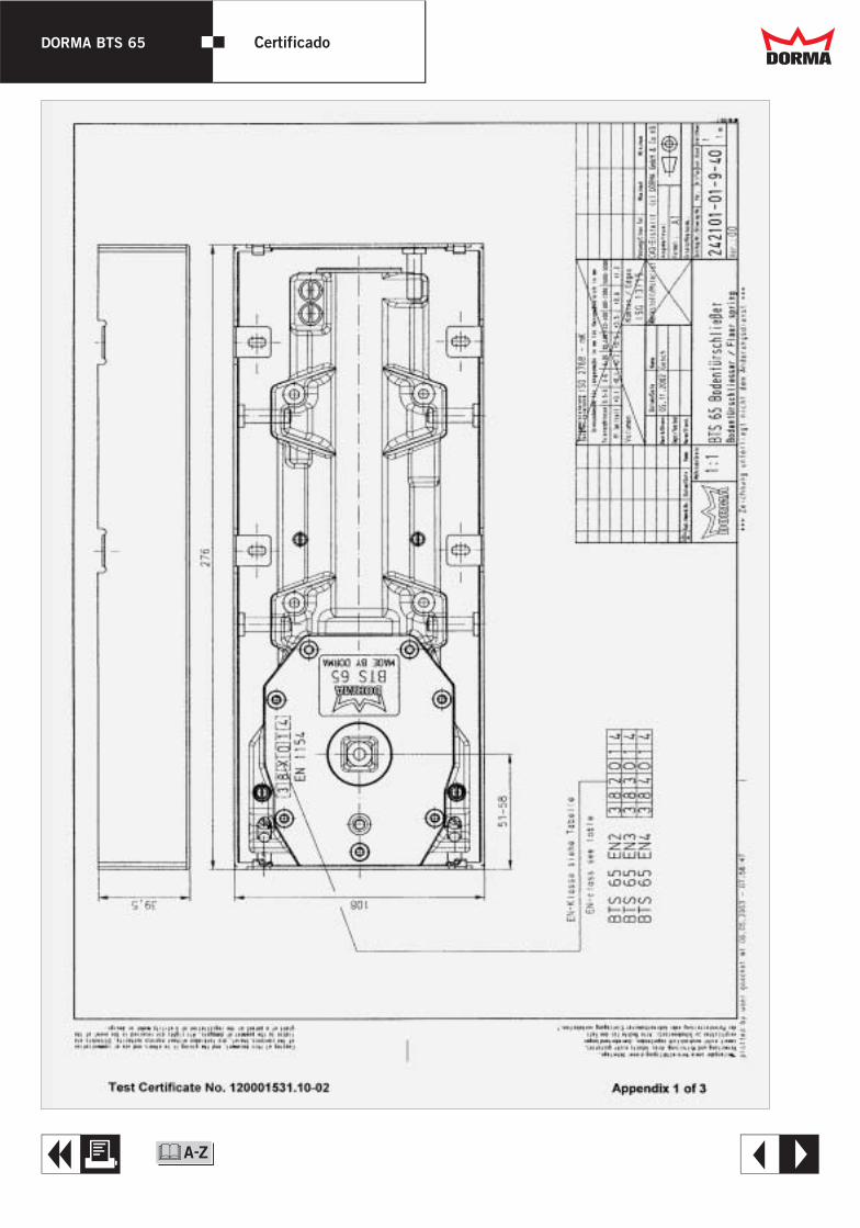
DORMA BTS 65 Certificado Dd
EQ &

DORMA BTS 65 Certificado Dd
EQ &
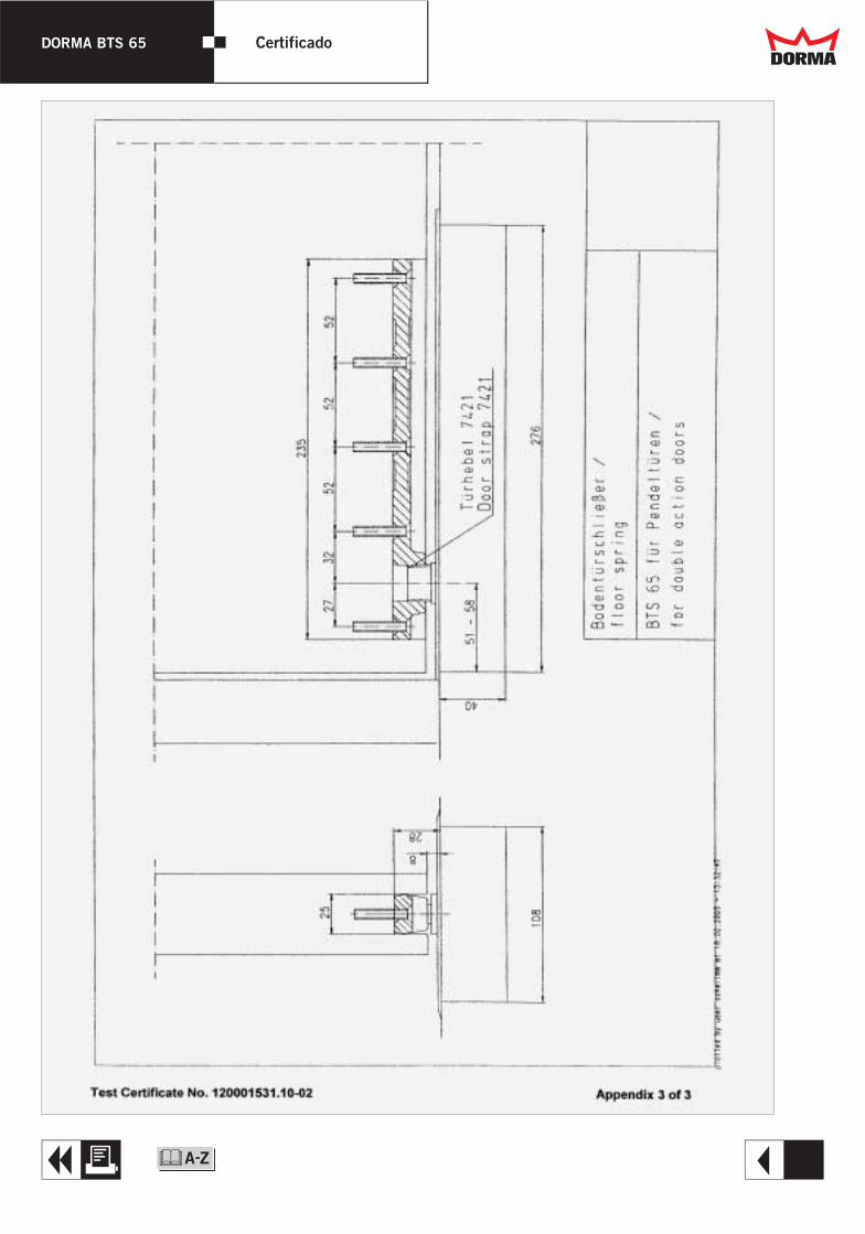
DORMA BTS 65 Certificado Dd
RQ &