decodificador de funciones con servousuaris.tinet.cat/fmco/download/dccfuncservo_manual.pdfdiy...
TRANSCRIPT

http://www.fut.es/~fmco http://usuaris.tinet.org/fmco
Decodificador de funciones con servo 1.- Introducción Este decodificador de funciones posee dos salidas para servo de los que se puede programar la velocidad de movimiento y el recorrido y dos salidas para activar LED.
- Dirección de locomotoras corta y larga hasta 9999
- Control de las salidas seleccionable entre F1 y F8
- Dos salidas para servos y dos salidas para activar LED programables
- Selección de funciones activas en modo analógico
Fotos de Hans Deloof
2.- El circuito El circuito es muy simple estando gobernado por el PIC12F629 con cuatro salidas para función. Cuando programéis el PIC12F629 tened en cuenta que se ha de conservar el valor de la última posición, por lo que quizás primero sea conveniente leer el PIC y apuntar el valor para luego comprobarlo una vez programado.

http://www.fut.es/~fmco http://usuaris.tinet.org/fmco
Para controlar un servo tendremos que aplicar un pulso de duración y frecuencia específicos, todos los servos disponen de tres cables dos para alimentación Vcc y Gnd y otro cable para aplicar los pulsos de control que harán que el servo se mueva a la posición indicada por la anchura del pulso (pin 1 de cada conector para el servo) La duración del pulso normalmente varía entre 1ms y 2ms con una separación de 20ms entre pulsos, la posición central corresponde con un pulso de 1,5ms.
En la siguiente tabla están indicados los valores aproximados de control y disposición de cables de varias marcas que comercializan servos. Comprobad el orden correcto de los cables antes de conectar el servo.
Duración pulso (ms) Cables Fabricante min. centro máx. Hz +Vcc GND Pulsos
Futaba 0.9 1.5 2.1 50 Rojo Negro blanco Hitech 0.9 1.5 2.1 50 Rojo Negro amarillo
Graupner/Jr 0.8 1.5 2.2 50 Rojo Marrón naranja Multiplex 1.05 1.6 2.15 40 Rojo Negro amarillo
Robbe 0.65 1.3 1.95 50 Rojo Negro blanco
Estos son los conectores que suelen usar:

http://www.fut.es/~fmco http://usuaris.tinet.org/fmco
3.- Programación Esta es la lista de CV usados:
CV Valor Valor defecto Descripción 1 1..99 3 Dirección corta decoder 7 10 10 Revisión (solo lectura) 8 13 13 ID del fabricante: 13. DIY decoder (decodificador casero, solo lectura)
13 0..255 0 Funciones F1 a F8 activas en analógico 14 0..3 3 Funciones FL, FR activas en analógico 17 192..231 192 Dirección larga (byte alto) 18 0..255 100 Dirección larga (byte bajo) 19 0..255 0 Dirección del consist
Configuración decodificador: 29 Bit: 0 1 0
1 2 3 4 5 6 7
0 1 1 0 0 0 0 0
Dirección normal 14 pasos Solo DCC - - Dirección corta en CV1 - -
Dirección invertida 28/128 pasos DCC y analógico - - Dirección larga en CV17,CV18 - -
33 0..51 1 Salidas activas con FL (Luz marcha adelante) 34 0..51 2 Salidas activas con FR (Luz marcha atrás) 35 0..51 16 Salidas activas con F1 36 0..51 32 Salidas activas con F2 37 0..51 0 Salidas activas con F3 38 0..51 0 Salidas activas con F4 39 0..51 0 Salidas activas con F5 40 0..51 0 Salidas activas con F6 41 0..51 0 Salidas activas con F7 42 0..51 0 Salidas activas con F8 50 32..255 78 Espaciado (en 256us) 51 1..105 50 Recorrido servo 1 (en 10us) 52 1..255 1 Velocidad servo 1 53 1..105 50 Recorrido servo 2 (en 10us) 54 1..255 1 Velocidad servo 2
CV1: Dirección del decoder (byte bajo) CV7: Versión: 1.0 (solo lectura) CV8: ID del fabricante: 13. DIY decoder (decodificador casero, solo lectura). Si se escribe el
valor 33 se reseteara el decoder con los valores por defecto. CV13: Funciones F1 a F8 activas en analógico. Selecciona el estado de cada función en
funcionamiento analógico (sin señal DCC). Para calcular el valor a programar en los CV que se programan cambiando sus bits se puede usar la tabla siguiente, (en este ejemplo CV13 lo calculamos para activar las funciones F2 y F6 en funcionamiento analógico).
Bit 7
F8 6
F7 5
F6 4
F5 3
F4 2
F3 1
F2 0
F1 CV13 0 0 1 0 0 0 1 0 Multiplicador 128x 64x 32x 16x 8x 4x 2x 1x Sumandos 0 0 32 0 0 0 2 0 Resultado 32 + 2 = 34

http://www.fut.es/~fmco http://usuaris.tinet.org/fmco
CV14: Funciones FL, FR activas en analógico. (FL: Luz marcha adelante, FR: Luz marcha atrás)
CV14 FL FR 0 1 X 2 X 3 X X
CV17: Dirección larga del decoder (byte alto) CV18: Dirección larga del decoder (byte bajo) CV19: Dirección del consist CV29: Configuración del decoder. Seleccionar los valores igual que en la locomotora, (pasos de
velocidad, dirección de marcha, etc.) Para calcular el valor a programar en los CV que se programan cambiando sus bits se puede usar la tabla siguiente, (en este ejemplo CV29 lo calculamos para 28/128 pasos y utilizar dirección extendida).
Bit 7 6 5 4 3 2 1 0 CV29 0 0 1 0 0 0 1 0 Multiplicador 128x 64x 32x 16x 8x 4x 2x 1x Sumandos 0 0 32 0 0 0 2 0 Resultado 32 + 2 = 34
Podemos programar los CV tanto en modo Paged como en modo Direct y en la vía principal (PoM). CV33-CV42: Las salidas que se activan con cada tecla de función de la central se indican en estos CV
de acuerdo con la siguiente tabla que muestra los valores por defecto, un 1 en un bit activa esa salida:
Bit
CV Descripción 7
6
5 SERVO2
4 SERVO1
3
2
1 FB
0 FA
33 FL (adelante) 0 0 0 0 0 0 0 1 34 FR (atrás) 0 0 0 0 0 0 1 0 35 F1 0 0 0 1 0 0 0 0 36 F2 0 0 1 0 0 0 0 0 37 F3 0 0 0 0 0 0 0 0 38 F4 0 0 0 0 0 0 0 0 39 F5 0 0 0 0 0 0 0 0 40 F6 0 0 0 0 0 0 0 0 41 F7 0 0 0 0 0 0 0 0 42 F8 0 0 0 0 0 0 0 0
Con la tecla de activación de luces (FL, F0 o * según la central) cuando la locomotora va marcha adelante se usa CV33 y cuando va marcha atrás se usa CV34. Por defecto, la tecla F0 activa la salida FA cuando va marcha adelante y activa la salida FB cuando va marcha atrás, la tecla F1 activa el servo 1 y la tecla F2 el servo 2, las teclas F3 a F8 no tienen asignada ninguna función. También se puede activar más de una función a la vez con una sola tecla.
CV50: Espaciado. Los pulsos se repiten con un espacio entre ellos de 20ms. Variando este valor
se influye en la velocidad. CV51: Recorrido servo 1.
El centro del recorrido corresponde a 1,5ms, el extremo a 2ms (valor 50) o 2,5ms para los servos Hitec (valor 100)
CV52: Velocidad servo 1. Son los pulsos por cada posición que se envían al servo, cuanto mas pulsos mas lento el movimiento
CV53: Recorrido servo 2. CV54: Velocidad servo 2.

http://www.fut.es/~fmco http://usuaris.tinet.org/fmco
Function decoder with servo 1.- Introduction This function decoder has two outputs for servo of which it is possible to be programmed the speed and the range of movement and outputs to activate LED.
- Locomotives addresses short and
long up to 9999 - Output controls selectable between
F1 and F8 - Two outputs for servo and two
outputs for LED programmable. - Selection of active functions in
analog mode
Photos by Hans Deloof
2.- The schematic The circuit is very simple, a PIC12F629 with four outputs for functions. When program the PIC12F629 remember that it has to preserve the value of the last memory position, so may be useful to read first the PIC and take note the value and then check once programmed.

http://www.fut.es/~fmco http://usuaris.tinet.org/fmco
To control a servo we will have to apply a pulse of specific duration and frequency, the servo have three wires, two for feeding Vcc and Gnd and another wire to apply the control pulses that will cause that the servo moves to the position indicated by the width of the pulse (pin 1 of each servo connector) The duration of the pulse normally varies between 1ms and 2ms with a separation of 20ms between pulses; the central position corresponds to a pulse of 1,5ms.
In the following table the approximated values of control and wire disposition of several manufacturers. You have to verify the correct order of wires before connecting the servo.
Pulse Duration (ms) Wires Manufacturer min. centre max. Hz +Vcc GND Pulses
Futaba 0.9 1.5 2.1 50 Red Black White Hitech 0.9 1.5 2.1 50 Red Black Yellow
Graupner/Jr 0.8 1.5 2.2 50 Red Brown Orange Multiplex 1.05 1.6 2.15 40 Red Black Yellow
Robbe 0.65 1.3 1.95 50 Red Black White
These are the connectors that usually use:

http://www.fut.es/~fmco http://usuaris.tinet.org/fmco
3.- Programming This is the list of the used CV:
CV Value Default Value Descripction 1 1..99 3 Decoder short address 7 10 10 Revision (only read) 8 13 13 Manufacturer ID: 13. DIY decoder (homemade decoder, only read)
13 0..255 0 Function F1 to F8 active in analog mode 14 0..3 3 Functions FL, FR active in analog mode 17 192..231 192 Decoder long address (high byte) 18 0..255 100 Decoder long address (low byte) 19 0..255 0 Consist address
Decoder configuration 29 Bit: 0 1 0
1 2 3 4 5 6 7
0 1 1 0 0 0 0 0
Normal direction 14 steps Only DCC - - Short address in CV1 - -
Reversed direction 28/128 steps DCC and analog - - Long address in CV17,CV18 - -
33 0..51 1 Output active with FL (Front light) 34 0..51 2 Output active with FR (Rear light) 35 0..51 16 Output active with F1 36 0..51 32 Output active with F2 37 0..51 0 Output active with F3 38 0..51 0 Output active with F4 39 0..51 0 Output active with F5 40 0..51 0 Output active with F6 41 0..51 0 Output active with F7 42 0..51 0 Output active with F8 50 32..255 78 Space (in 256us) 51 1..105 50 Range servo 1 (in 10us) 52 1..255 1 Speed servo 1 53 1..105 50 Range servo 2 (in 10us) 54 1..255 1 Speed servo 2
CV1: Decoder short address CV7: Version: 2.0 (only read) CV8: Manufactured ID: 13. DIY decoder (homemade decoder, only read). If you write the
value 33 the decoder is reset with the default values. CV13: Functions F1 through F8 active in analog. Select the status of each function in analog
operation (no signal DCC). To calculate the value programmed in the CV that are programmed by changing their bits
can be used the following table (in this example CV13 activate functions F2 and F6 in analog).
Bit 7 F8
6 F7
5 F6
4 F5
3 F4
2 F3
1 F2
0 F1
CV13 0 0 1 0 0 0 1 0 Multiplier 128x 64x 32x 16x 8x 4x 2x 1x Adder 0 0 32 0 0 0 2 0 Result 32 + 2 = 34

http://www.fut.es/~fmco http://usuaris.tinet.org/fmco
CV14: Functions FL, FR active in analog. (FL: front light, FR: Rear light)
CV14 FL FR 0 1 X 2 X 3 X X
CV17: Decoder long address (high byte) CV18: Decoder long address (low byte) CV19: Consist address CV29: Configuration of the decoder. Select values as in the locomotive, (steps speed, direction
of movement, etc.). To calculate the value programmed in the CV that are programmed by changing their bits
can be used the following table (in this example CV29 is programmed for 28/128 steps and long addressing).
Bit 7 6 5 4 3 2 1 0 CV29 0 0 1 0 0 0 1 0 Multiplier 128x 64x 32x 16x 8x 4x 2x 1x Adder 0 0 32 0 0 0 2 0 Result 32 + 2 = 34
We can program the CV in Paged, Direct and in PoM mode. CV33-CV42: The outputs that are activated with each key function are set in these CV according to the
following table shows the default values, a 1 in a bit activate the corresponding output:
Bit CV
Description 7
6
5 SERVO2
4 SERVO1
3
2
1 FB
0 FA
33 FL (forward) 0 0 0 0 0 0 0 1 34 FR (backward) 0 0 0 0 0 0 1 0 35 F1 0 0 0 1 0 0 0 0 36 F2 0 0 1 0 0 0 0 0 37 F3 0 0 0 0 0 0 0 0 38 F4 0 0 0 0 0 0 0 0 39 F5 0 0 0 0 0 0 0 0 40 F6 0 0 0 0 0 0 0 0 41 F7 0 0 0 0 0 0 0 0 42 F8 0 0 0 0 0 0 0 0
With the key activation of lights (FL, F0 or * depending on command station) when the locomotive goes forward is used CV33 and when goes backwards is used CV34. By default, the key F0 active exit FA when goes forward and active output FB when goes backwards, the F1 key active servo 1 and key F2 activates servo 2FD. F3 through F8 keys are not assigned any role. You can also enable more than one function at once with a single key.
CV50: Space. The pulses are repeated with a space among them of 20ms. Varying this value is
influenced in the speed. CV51: Range servo 1
The mid-range corresponds to 1,5ms, the end to 2ms (value 50) or 2,5ms for servo the Hitec (value 100)
CV52: Speed servo 1. They are the pulses by each position that are sent to the servo, whichever more pulses more slow the movement is.
CV53: Range servo 2 CV54: Speed servo 2.

http://www.fut.es/~fmco
http://usuaris.tinet.org/fmco
Functie decoder met servo
1.- Introductie
Deze decoder heeft 2 uitgangen voor servo’s (met de mogelijkheid om de snelheid en de reikwijdte in te
stellen) en 2 uitgangen voor LED’s.
- Locomotiefadres kort en lang tot 9999
- Uitgangen selecteerbaar dmv F1 en F8
- 2 programmeerbare uitgangen voor
servo’s en 2 voor LED’s.
- Selectie van actieve functies in analoge
modus
Foto’s door Hans Deloof
2.- Het circuit
Het circuit is erg simpel, een PIC12F629 met 4 uitgangen. Wanneer je de PIC12F629 programmeert dien
je de laatste geheugen geheugenpositie te bewaren, dus eerst de PIC lezen en bewaren om zo een controle
uit te voeren na programmatie.

http://www.fut.es/~fmco
http://usuaris.tinet.org/fmco
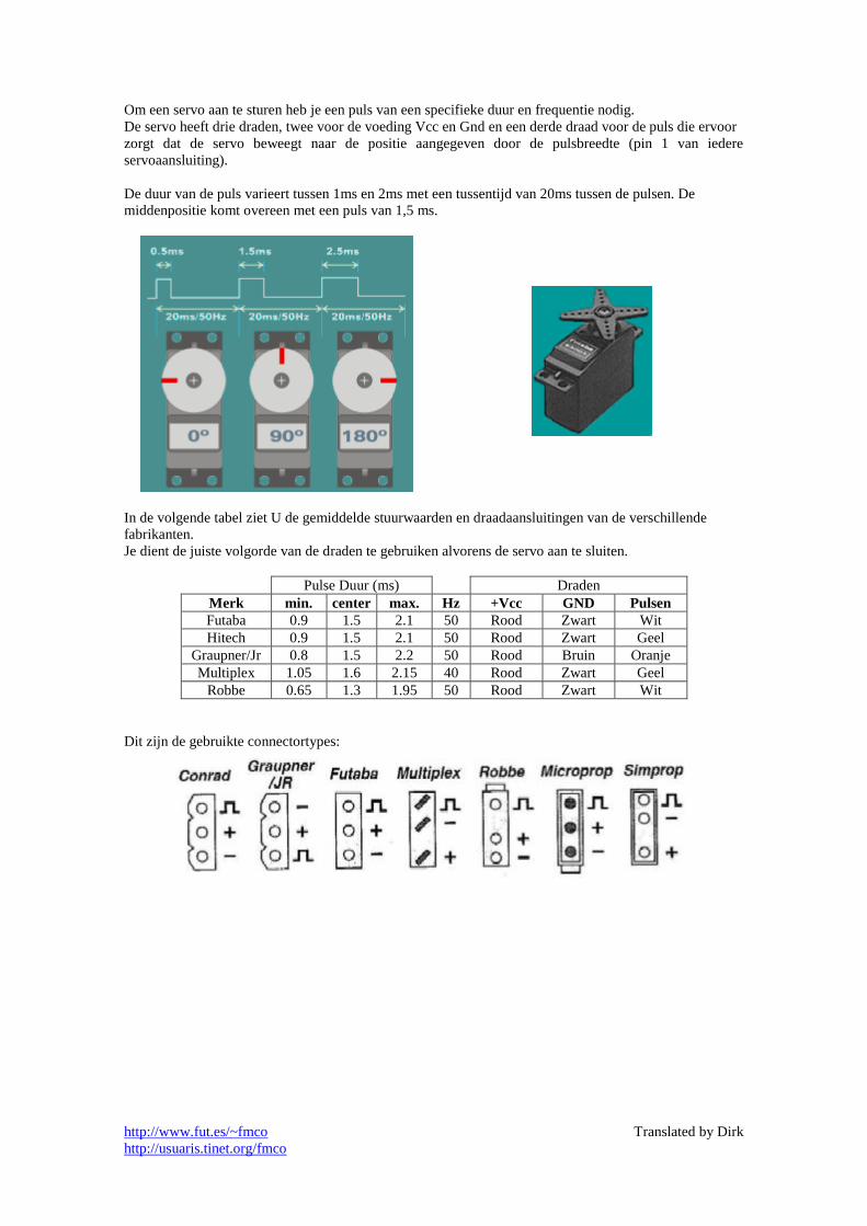
Om een servo aan te sturen heb je een puls van een specifieke duur en frequentie nodig.
De servo heeft drie draden, twee voor de voeding Vcc en Gnd en een derde draad voor de puls die ervoor
zorgt dat de servo beweegt naar de positie aangegeven door de pulsbreedte (pin 1 van iedere
servoaansluiting).
De duur van de puls varieert tussen 1ms en 2ms met een tussentijd van 20ms tussen de pulsen. De
middenpositie komt overeen met een puls van 1,5 ms.
In de volgende tabel ziet U de gemiddelde stuurwaarden en draadaansluitingen van de verschillende
fabrikanten.
Je dient de juiste volgorde van de draden te gebruiken alvorens de servo aan te sluiten.
Pulse Duur (ms) Draden
Merk min. center max. Hz +Vcc GND Pulsen
Futaba 0.9 1.5 2.1 50 Rood Zwart Wit
Hitech 0.9 1.5 2.1 50 Rood Zwart Geel
Graupner/Jr 0.8 1.5 2.2 50 Rood Bruin Oranje
Multiplex 1.05 1.6 2.15 40 Rood Zwart Geel
Robbe 0.65 1.3 1.95 50 Rood Zwart Wit
Dit zijn de gebruikte connectortypes:

http://www.fut.es/~fmco
http://usuaris.tinet.org/fmco
3.- Programmering
Dit is de lijst van de gebruikte CV’s:
CV Waarde Standaard Descripction
1 1..99 3 Decoder adres
7 10 10 Versie (enkel lezen)
8 13 13 Fabrikant ID: 13. DIY decoder (homemade decoder, enkel lezen)
13 0..255 0 Functies F1 tot F8 actief in analoge modus
14 0..3 3 Functies FL, FR actief in analoge modus
17 192..231 192 Decoder adres (hoge byte)
18 0..255 100 Decoder lang adres (lage byte)
19 0..255 0 Consist adres
29 Bit: Decoder configuratie:
0 1
0
1
2
3
4
5
6
7
0
1
1
0
0
0
0
0
Voorwaartse richting
14 stappen
Enkel DCC
-
-
Kort adres in CV1
-
-
Achterwaartse richting
28/128 stappen
DCC en analoog
-
-
Lang adres in CV17,CV18
-
-
33 0..51 1 Uitgang actief met FL (Front light)
34 0..51 2 Uitgang actief met FR (Rear light)
35 0..51 16 Uitgang actief met F1
36 0..51 32 Uitgang actief met F2
37 0..51 0 Uitgang actief met F3
38 0..51 0 Uitgang actief met F4
39 0..51 0 Uitgang actief met F5
40 0..51 0 Uitgang actief met F6
41 0..51 0 Uitgang actief met F7
42 0..51 0 Uitgang actief met F8
50 32..255 78 Spatie (in 256us)
51 1..105 50 Bereik servo 1 (in 10us)
52 1..255 1 Snelheid servo 1
53 1..105 50 Bereik servo 2 (in 10us)
54 1..255 1 Snelheid servo 2
CV1: Decoder kort adres
CV7: Version: 2.0 (enkel lezen)
CV8: Fabrikant ID: 13. DIY decoder (zelfbouw decoder, enkel lezen). Indien je waarde 33
schrijft naar de decoder dan voer je een reset uit.
CV13: Functie F1 tot F8 actief in analoge modus. Selecteer de status van iedere functie in
analoge modus (geen DCC signaal).
Om de CV waarde te berekenen om te programmeren kan je de onderstaande tabel
gebruiken. (in dit voorbeeld dient CV13 om de functies F2 en F6 in analoge modus te
activeren).
Bit 7
F8
6
F7
5
F6
4
F5
3
F4
2
F3
1
F2
0
F1 CV13 0 0 1 0 0 0 1 0
Vermenigvuldiger 128x 64x 32x 16x 8x 4x 2x 1x
Som 0 0 32 0 0 0 2 0
Resultaat 32 + 2 = 34

http://www.fut.es/~fmco
http://usuaris.tinet.org/fmco
CV14: Functies FL, FR actief in analoge modus. (FL: front light, FR: Rear light)
CV14 FL FR 0
1 X
2 X
3 X X
CV17: Decoder lang address (hoge byte)
CV18: Decoder lang address (lage byte)
CV19: Consist adres
CV29: Configuratie van de decoder. Selecteer waarden zoals de lokdecoder, (aantal stappen,
snelheid, richting, enz...).
Om de CV waarde te berekenen om te programmeren kan je de onderstaande tabel
gebruiken. (in dit voorbeeld is CV29 gebruikt voor 28/128 stappen en lange adressering).
Bit 7 6 5 4 3 2 1 0 CV29 0 0 1 0 0 0 1 0
Vermenigvulder 128x 64x 32x 16x 8x 4x 2x 1x
Som 0 0 32 0 0 0 2 0
Resultaat 32 + 2 = 34
De programmatie kan gedaan worden in Paged-, Direct- en in PoM mode.
CV33-CV42: De uitgangen die zijn geactiveerd met iedere functie staan in dit CV met inachtname van
onderstaande tabelwaarden, een 1 in een bit activateert de desbetreffende uitgang:
CV
Omschrijving
Bit
7
6
5 SERVO2
4 SERVO1
3
2
1
FB
0
FA 33 FL (voorwaarts) 0 0 0 0 0 0 0 1
34 FR (achterwaarts) 0 0 0 0 0 0 1 0
35 F1 0 0 0 1 0 0 0 0
36 F2 0 0 1 0 0 0 0 0
37 F3 0 0 0 0 0 0 0 0
38 F4 0 0 0 0 0 0 0 0
39 F5 0 0 0 0 0 0 0 0
40 F6 0 0 0 0 0 0 0 0
41 F7 0 0 0 0 0 0 0 0
42 F8 0 0 0 0 0 0 0 0
Met het gebruik van de LED’s (FL, F0 of * afhankelijk van je command station): wanneer
de lokomotief voorwaarts gaat gebruikt hij CV33. Achterwaarts maakt de decoder
gebruik van CV34.
Standaardwaarden: F0 maakt uitgang FA actief bij voorwaartse richting en uitgang FB bij
achterwaartse richting. F1 maakt servo 1 actief en F2 servo 2. F3 tot F8 hebben geen
functie.
Je kan meerdere functies activeren dmv één toets.
CV50: Spatie. De pulsen worden herhaald met een spatie ertussen van 20ms. Door deze waarde
aan te passen verander je de snelheid.
CV51: Bereik servo 1
De middenwaarde komt overeen met 1,5ms, het einde 2ms (waarde 50) of 2,5ms voor de
Hitec-servo (waarde 100)
CV52: Snelheid servo 1. Dit zijn de pulsen van iedere positie die naar de servo gezonden
worden.Hoe meer pulsen hoe trager de beweging. CV53: Bereik servo 2
CV54: Snelheid servo 2.

DCC_Func_Servo
DCC
SERVO1 (F1)
SERVO2 (F2)
OUT1 (FL)
OUT2 (FR)
http://www.fut.es/~fmco
+ X1-1
X1-2GND
INOUT
IC1
GP0 7GP1 6GP2 5GP3/MC 4GP4/COUT 3VDD1
VSS8
GP5/CIN 2IC2
123
JP3
123
JP4
AC
1A
C2
-+
B1C1C2
R1
X2-1
X2-2
X2-3
R2
R3
LED2
LED1
7805
PIC12F629
100uF100nF
22K
GND
GND GNDGND
GND
GND
470R
470R

DCC-Func-Servo Partlist
Part Value Device
B1 B40C1000 puente diodos / rectifierC1 100uF condensador / capacitorC2 100nF IC1 7805 regulador voltage / voltage regulatorIC2 PIC12F629 JP3 conector pin / pin headerJP4 R1 22K resistencia / resistorR2 470R R3 470R
F. Cañadahttp://www.fut.es/~fmco

http://www.fut.es/~fmco Translated by Dirk
http://usuaris.tinet.org/fmco
Functie decoder met servo
1.- Introductie
Deze decoder heeft 2 uitgangen voor servo’s (met de mogelijkheid om de snelheid en de reikwijdte in te
stellen) en 2 uitgangen voor LED’s.
- Locomotiefadres kort en lang tot 9999
- Uitgangen selecteerbaar dmv F1 en F8
- 2 programmeerbare uitgangen voor
servo’s en 2 voor LED’s (20mA).
- Selectie van actieve functies in analoge
modus
Foto’s door Hans Deloof
2.- Het circuit
Het circuit is erg simpel, een PIC12F629 met 4 uitgangen. Wanneer je de PIC12F629 programmeert dien
je de laatste geheugen geheugenpositie te bewaren, dus eerst de PIC lezen en bewaren om zo een controle
uit te voeren na programmatie.
http://www.fut.es/~fmco Translated by Dirk
http://usuaris.tinet.org/fmco
Om een servo aan te sturen heb je een puls van een specifieke duur en frequentie nodig.
De servo heeft drie draden, twee voor de voeding Vcc en Gnd en een derde draad voor de puls die ervoor
zorgt dat de servo beweegt naar de positie aangegeven door de pulsbreedte (pin 1 van iedere
servoaansluiting).
De duur van de puls varieert tussen 1ms en 2ms met een tussentijd van 20ms tussen de pulsen. De
middenpositie komt overeen met een puls van 1,5 ms.
In de volgende tabel ziet U de gemiddelde stuurwaarden en draadaansluitingen van de verschillende
fabrikanten.
Je dient de juiste volgorde van de draden te gebruiken alvorens de servo aan te sluiten.
Pulse Duur (ms) Draden
Merk min. center max. Hz +Vcc GND Pulsen
Futaba 0.9 1.5 2.1 50 Rood Zwart Wit
Hitech 0.9 1.5 2.1 50 Rood Zwart Geel
Graupner/Jr 0.8 1.5 2.2 50 Rood Bruin Oranje
Multiplex 1.05 1.6 2.15 40 Rood Zwart Geel
Robbe 0.65 1.3 1.95 50 Rood Zwart Wit
Dit zijn de gebruikte connectortypes:

http://www.fut.es/~fmco Translated by Dirk
http://usuaris.tinet.org/fmco
3.- Programmering
Dit is de lijst van de gebruikte CV’s:
CV Waarde Standaard Descripction
1 1..99 3 Decoder adres
7 10 10 Versie (enkel lezen)
8 13 13 Fabrikant ID: 13. DIY decoder (homemade decoder, enkel lezen)
13 0..255 0 Functies F1 tot F8 actief in analoge modus
14 0..3 3 Functies FL, FR actief in analoge modus
17 192..231 192 Decoder adres (hoge byte)
18 0..255 100 Decoder lang adres (lage byte)
19 0..255 0 Consist adres
29 Bit: Decoder configuratie:
0 1
0
1
2
3
4
5
6
7
0
1
1
0
0
0
0
0
Voorwaartse richting
14 stappen
Enkel DCC
-
-
Kort adres in CV1
-
-
Achterwaartse richting
28/128 stappen
DCC en analoog
-
-
Lang adres in CV17,CV18
-
-
33 0..51 1 Uitgang actief met FL (Front light)
34 0..51 2 Uitgang actief met FR (Rear light)
35 0..51 16 Uitgang actief met F1
36 0..51 32 Uitgang actief met F2
37 0..51 0 Uitgang actief met F3
38 0..51 0 Uitgang actief met F4
39 0..51 0 Uitgang actief met F5
40 0..51 0 Uitgang actief met F6
41 0..51 0 Uitgang actief met F7
42 0..51 0 Uitgang actief met F8
50 32..255 78 Spatie (in 256us)
51 1..105 50 Bereik servo 1 (in 10us)
52 1..255 1 Snelheid servo 1
53 1..105 50 Bereik servo 2 (in 10us)
54 1..255 1 Snelheid servo 2
CV1: Decoder kort adres
CV7: Version: 2.0 (enkel lezen)
CV8: Fabrikant ID: 13. DIY decoder (zelfbouw decoder, enkel lezen). Indien je waarde 33
schrijft naar de decoder dan voer je een reset uit.
CV13: Functie F1 tot F8 actief in analoge modus. Selecteer de status van iedere functie in
analoge modus (geen DCC signaal).
Om de CV waarde te berekenen om te programmeren kan je de onderstaande tabel
gebruiken. (in dit voorbeeld dient CV13 om de functies F2 en F6 in analoge modus te
activeren).
Bit 7
F8
6
F7
5
F6
4
F5
3
F4
2
F3
1
F2
0
F1 CV13 0 0 1 0 0 0 1 0
Vermenigvuldiger 128x 64x 32x 16x 8x 4x 2x 1x
Som 0 0 32 0 0 0 2 0
Resultaat 32 + 2 = 34

http://www.fut.es/~fmco Translated by Dirk
http://usuaris.tinet.org/fmco
CV14: Functies FL, FR actief in analoge modus. (FL: front light, FR: Rear light)
CV14 FL FR 0
1 X
2 X
3 X X
CV17: Decoder lang address (hoge byte)
CV18: Decoder lang address (lage byte)
CV19: Consist adres
CV29: Configuratie van de decoder. Selecteer waarden zoals de lokdecoder, (aantal stappen,
snelheid, richting, enz...).
Om de CV waarde te berekenen om te programmeren kan je de onderstaande tabel
gebruiken. (in dit voorbeeld is CV29 gebruikt voor 28/128 stappen en lange adressering).
Bit 7 6 5 4 3 2 1 0 CV29 0 0 1 0 0 0 1 0
Vermenigvulder 128x 64x 32x 16x 8x 4x 2x 1x
Som 0 0 32 0 0 0 2 0
Resultaat 32 + 2 = 34
De programmatie kan gedaan worden in Paged-, Direct- en in PoM mode.
CV33-CV42: De uitgangen die zijn geactiveerd met iedere functie staan in dit CV met inachtname van
onderstaande tabelwaarden, een 1 in een bit activateert de desbetreffende uitgang:
CV
Omschrijving
Bit
7
6
5 SERVO2
4 SERVO1
3
2
1
FB
0
FA 33 FL (voorwaarts) 0 0 0 0 0 0 0 1
34 FR (achterwaarts) 0 0 0 0 0 0 1 0
35 F1 0 0 0 1 0 0 0 0
36 F2 0 0 1 0 0 0 0 0
37 F3 0 0 0 0 0 0 0 0
38 F4 0 0 0 0 0 0 0 0
39 F5 0 0 0 0 0 0 0 0
40 F6 0 0 0 0 0 0 0 0
41 F7 0 0 0 0 0 0 0 0
42 F8 0 0 0 0 0 0 0 0
Met het gebruik van de LED’s (FL, F0 of * afhankelijk van je command station): wanneer
de lokomotief voorwaarts gaat gebruikt hij CV33. Achterwaarts maakt de decoder
gebruik van CV34.
Standaardwaarden: F0 maakt uitgang FA actief bij voorwaartse richting en uitgang FB bij
achterwaartse richting. F1 maakt servo 1 actief en F2 servo 2. F3 tot F8 hebben geen
functie.
Je kan meerdere functies activeren dmv één toets.
CV50: Spatie. De pulsen worden herhaald met een spatie ertussen van 20ms. Door deze waarde
aan te passen verander je de snelheid.
CV51: Bereik servo 1
De middenwaarde komt overeen met 1,5ms, het einde 2ms (waarde 50) of 2,5ms voor de
Hitec-servo (waarde 100)
CV52: Snelheid servo 1. Dit zijn de pulsen van iedere positie die naar de servo gezonden
worden.Hoe meer pulsen hoe trager de beweging. CV53: Bereik servo 2
CV54: Snelheid servo 2.

http://www.fut.es/~fmco Translated by Dirk
http://usuaris.tinet.org/fmco

http://www.fut.es/~fmco Translated by Dirk
http://usuaris.tinet.org/fmco
http://www.fut.es/~fmco Translated by Dirk
http://usuaris.tinet.org/fmco
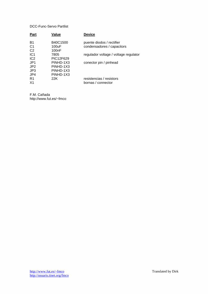
DCC-Func-Servo Partlist Part Value Device
B1 B40C1500 puente diodos / rectifier C1 100uF condensadores / capacitors C2 100nF IC1 7805 regulador voltage / voltage regulator IC2 PIC12F629 JP1 PINHD-1X3 conector pin / pinhead JP2 PINHD-1X3 JP3 PINHD-1X3 JP4 PINHD-1X3 R1 22K resistencias / resistors X1 bornas / connector F.M. Cañada http://www.fut.es/~fmco