control control
DESCRIPTION
Todos de control para todosTRANSCRIPT
MINISTERIODE ECONOMÍAY COMPETITIVIDAD
1250Marzo, 2012
Informes Técnicos Ciemat
GOBIERNODE ESPAÑA Centro de Investigaciones
Energéticas, Medioambientales
y Tecnológicas
Sliding Mode Control ofa Tokamak Transformer
J. A. RomeroS. CodaF. FeliciJ-M. MoretJ. PaleyG. SevillanoI. GarridoH. B. Le

Informes Técnicos Ciemat 1250Marzo, 2012
Laboratorio Nacional de Fusión por Confinamiento Magnético
Sliding Mode Control ofa Tokamak Transformer
J. A. Romero1
S. Coda2
F. Felici2
J-M. Moret2
J. Paley2
G. Sevillano3
I. Garrido3
H. B. Le2
1Laboratorio Nacional de Fusión, Ciemat, Madrid 280402 Ecole Polytechnique Fédérale de Lausanne (EPFL), Centre de Recherches enPhysique des Plasmas, Association EURATOM-Confédération Suisse, CH-1015Laussanne, Switzerland.3Euskal Herriko Unibertsitatea (EHU), Plaza Casilla 3, 48012, Bilbao, Spain

Toda correspondencia en relación con este trabajo debe dirigirse al Servicio de In-formación y Documentación, Centro de Investigaciones Energéticas, Medioambientales y Tecnológicas, Ciudad Universitaria, 28040-MADRID, ESPAÑA.
Las solicitudes de ejemplares deben dirigirse a este mismo Servicio.
Los descriptores se han seleccionado del Thesauro del DOE para describir las ma-terias que contiene este informe con vistas a su recuperación. La catalogación se ha hecho utilizando el documento DOE/TIC-4602 (Rev. 1) Descriptive Cataloguing On-Line, y la cla-sificación de acuerdo con el documento DOE/TIC.4584-R7 Subject Categories and Scope publicados por el Office of Scientific and Technical Information del Departamento de Energía de los Estados Unidos.
Se autoriza la reproducción de los resúmenes analíticos que aparecen en esta pu-blicación.
Depósito Legal: M -26385-2011ISSN: 1135 - 9420NIPO: 721-12-017-5
Editorial CIEMAT
Catálogo general de publicaciones oficialeshttp://www.060.es
CLASIFICACIÓN DOE Y DESCRIPTORES
S70TOKAMAK DEVICES; PLASMA CONFINEMENT; TOROIDAL CONFIGURATION;CONTROL SYSTEMS; INDUCTANCE
Sliding Mode Control of a Tokamak Transformer
Romero, J. A,; Coda, S.; Felici, F.; Moret, J-M.; Paley, J.; Sevillano, G.; Garrido, I.; Le, H. B.
12 pp. 67 ref. 5 figs. 6 tables
Abstract:A novel inductive control system for a tokamak transformer is described. The system uses the flux change provided by the transformer primary coil to control the electric current and the internal inductance of the secondary plasma circuit load. The internal inductance control is used to regulate the slow flux penetration in the highly conductive plasma due to the skin effect, providing first-order control over the shape of the plasma current density profile. Inferred loop voltages at specific locations inside the plasma are included in a state feedback structure to improve controller perfor-mance. Experimental tests have shown that the plasma internal inductance can be controlled inductively for a whole pulse starting just 30ms after plasma breakdown. The details of the control system design are presented, including the transformer model, observer algorithms and controller design.
Control por Modo Deslizante del Transformador de un Tokamak
Romero, J. A,; Coda, S.; Felici, F.; Moret, J-M.; Paley, J.; Sevillano, G.; Garrido, I.; Le, H. B.
12 pp. 67 ref. 5 figs. 6 tables
Resumen:Se describe un novedoso sistema de control inductivo para el transformador de un tokamak. El sistema utiliza el cambio de flujo proporcionado por el primario del transformador para controlar la corriente y la inductancia del circuito de plasma secundario. La inductancia interna del plasma se utiliza para regular la penetración del flujo magnético en el mismo, que tiene lugar lentamente debido al efecto pelicular asociado con la alta conductividad eléctrica del plasma. De esta forma se proporciona un control de primer orden sobre la forma del perfil radial de corriente de plasma. Los voltajes por vuelta inferidos en dos posiciones internas al plasma se utilizan dentro de un esquema de realimentación de estados para mejorar las prestaciones del controlador. Las pruebas experimentales han mostrado que la inductancia del plasma se puede controlar inductivamente durante un pulso completo, comenzando en una fase temprana del mismo (30m después de la ruptura dieléctrica del gas). Se presentan los detalles del diseño del sistema, incluyendo el modelo del transformador utilizado, los algoritmos para los observadores y el diseño del controlador.
2
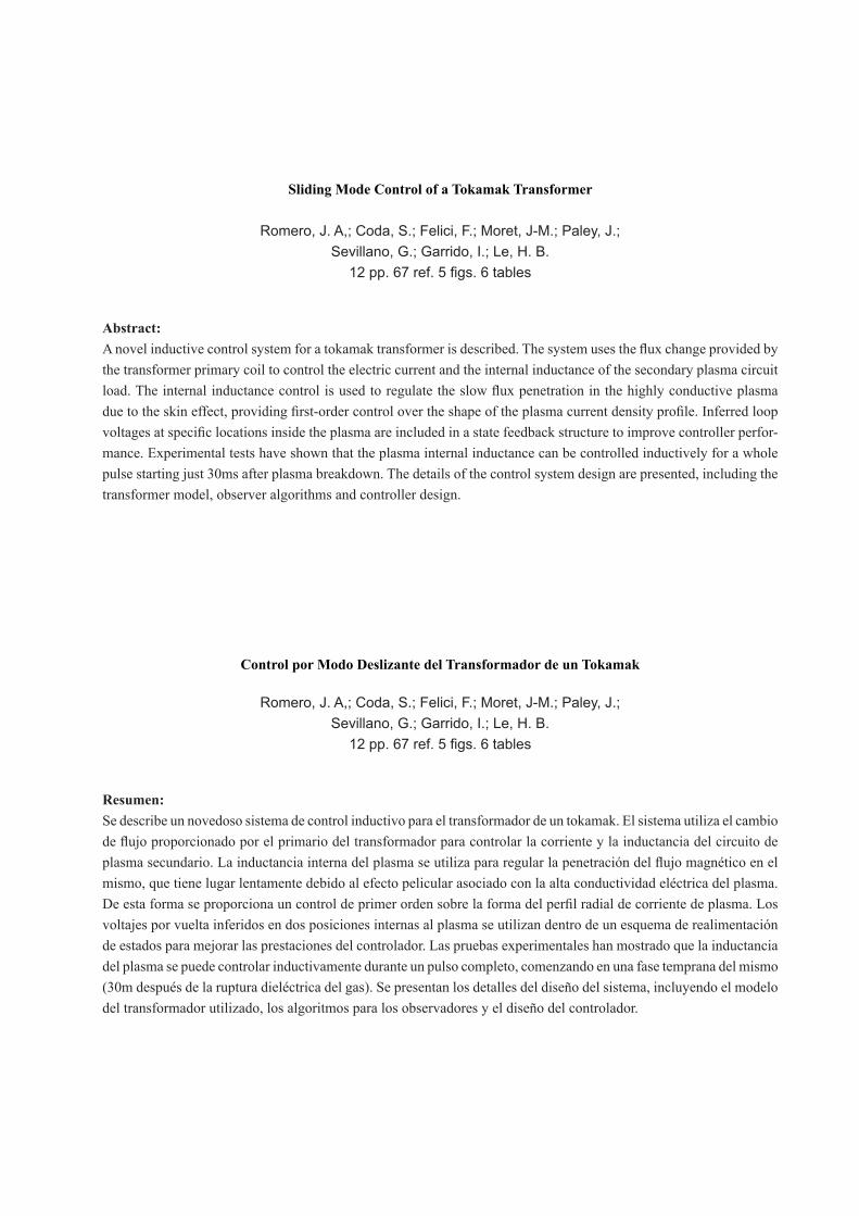
Fig. 1: Schematic view of an air core tokamak transformer . Plasma boundary is shown in pink, nested flux surfaces are superimposed with plasma cross-section shown in blue. Vacuum chamber and additional poloidal and toroidal field coils are not shown.
I. INTRODUCTION
Tokamaks are closed, high-vacuum toroidal devices relying on a magnetic field to confine high-temperature plasmas for the purpose of generating thermonuclear fusion energy [1]. A component of the magnetic field must necessarily be produced by a toroidal current in the plasma. Although various means of generating this current are available, in all present tokamaks it is primarily the result of pulsed transformer action. A typical tokamak has a set of external poloidal-field (PF) coils, including the transformer primary and additional control coils, concentric with the toroidal vacuum vessel. This is surrounded by further coils that generate a strong toroidal field, also necessary for confinement and stability (Fig. 1). The magnetically confined plasma inside the vacuum vessel acts as the transformer secondary. Alternative designs integrate the transformer primary coil and the toroidal field coils into single helical coils [2] . Just like in an induction oven, the plasma is ohmically heated by the current induced, up to some limit. Additional heating systems are used to increase its temperature close to thermonuclear conditions. The primary coil is named after its function as the ohmic heating (OH) coil. To sustain the plasma current the OH coil current must increase gradually up to its permissible limit, so tokamaks are inherently pulsed devices [3]. A fraction of the plasma current can also be driven non inductively due to the so-called bootstrap effect [4], which is related to the plasma pressure and helps to reduce the OH coil current ramp rate requirements, so the discharge duration can be extended. To extend the discharge even further, non inductive current drive sources have also been developed, which together with large bootstrap current fractions may one day allow steady state operation of future tokamak fusion reactors [5]. Tokamak magnetic control is concerned with the control of the total plasma current, plasma boundary shape and position using the currents in the PF system as the actuators. To maintain plasma confinement the plasma current must be kept between a lower and an upper limit that are roughly proportional to plasma density [6] and toroidal field, respectively [7],[8]. Magnetic control is essential to maintain the plasma current within the above mentioned operational limits, and also to keep the hot plasma away from the vacuum vessel walls [9]-[16]. The sum of the toroidal field and poloidal fields from PF coils and plasma current results in a toroidal-helical magnetic field structure [17]. The pitch of the toroidal- helical magnetic field (rotational transform) has a substantial impact on confinement and stability at several levels [18]. Since the radial profile shape of the rotational transform depends directly on the shape of the plasma current profile, it follows that the possibility of controlling any factor related to the shape of the current profile (such as the internal inductance, which is a measure of its peakedness) would be extremely valuable [19] -[22] . While several proofs of concept exist, current profile is not routinely controlled in present day tokamaks. Mainstream research focuses on current profile control using non inductive current drive sources [23]-[33]. However, the economy of future tokamaks may have to rely on having large bootstrap current fractions and/or pulsed operation [34] with limited power available for non inductive current drive actuators. Including the OH coil in the current profile control loop will reduce the power requirements of the non inductive current drive sources required for current profile control, since the general shape of the current profile can be easily manipulated by the transformer, at least transiently [35],[36]. Thus, a natural extension of the existing magnetic control systems is to add the control of the magnetic field structure inside the plasma without relying on (but benefiting from) the availability of non inductive current drive sources. The scheme would be particularly useful for the start up and termination phases of future pulsed reactors such as ITER [37] and high field ignition designs such as Ignitor [38], as well as of present day tokamak research facilities. In a tokamak, the transformer primary is the main current profile actuator during the ramp up phase, responsible for building almost the whole of the plasma current up to its flat-top value. However, in present-day tokamaks it generally does so in an uncontrolled manner, in the sense that only the total value of the plasma current (and not its radial profile shape) is feedback controlled in this phase. The power required to effect a given change in the current profile shape scales with the square of the plasma current, and the time required for it (skin time) scales with the plasma conductivity, an increasing function of the plasma electron temperature [39]. Therefore, the plasma current ramp up phase (when the plasma has not yet reached its maximum current and temperature) is in fact the optimal opportunity window for current profile control, since the actuators
3
require less power and time to steer the system towards the desired profile shapes. By contrast, corrections of large profile perturbations during the flat top require large power and settling times, so one should strive to approach the target profile sufficiently by the end of the ramp-up, and apply only minor corrections to correct perturbations as they arise. The same scheme could be used to avoid excessive current profile peaking during the plasma current ramp down phase. In this case the transformer relaxes its ramp rate gradually while the plasma current dissipates resistively, so a given current profile shape factor is maintained below pre-defined limits or is forced to follow a prescribed trajectory. To test these ideas, we have developed a control system for the ‘Tokamak à Configuration Variable’ (TCV), a research facility optimally suited for the testing of tokamak control systems [40]. The system has been implemented in a general purpose real time digital system architecture with a 10 kHz sampling rate [41] . The control system uses the internal inductance for profile regulation and the OH coil current ramp rate as the actuator. A tokamak transformer model with a lumped parameter formulation for the skin effect (section 2) is used for the design of plasma current and inductance sliding mode control systems (sections 3-6). Basic observers using the TCV magnetic sensor set have been developed (section 7), so the resulting control architecture can be implemented in any present or future reactor with a standard set of magnetic sensors [42]. Plasma internal inductance has been controlled over the whole plasma discharge using the OH coil as the actuator (section 8).
II. SKIN EFFECT TRANSFORMER MODEL
Distributed parameter simulations [43] are the preferred option to simulate current profile evolution during plasma current transients. There are many such distributed parameter models available [44]-[47], some control oriented [48], [49] and some even available in real time [50]. However, for control systems design a lumped parameter formulation is generally preferable [51], [52]. To develop the various control system designs presented in this paper we have used a transformer model that includes a lumped parameter formulation for the skin effect [53]. We call this model a skin effect transformer model to differentiate it from the standard transformer model where secondary inductance is a fixed parameter. The purpose of this control oriented model is to provide an explicit mathematical description for inductance and current dynamics as functions of the external PF currents, plasma resistance and non inductive current.
A cylindrical coordinate system ( ), ,r zφ is used, and the plasma is assumed to be axisymmetric about the z-axis. Only the
time evolving components ( )Zr BB , of the poloidal magnetic field and the toroidal component of the electric field E are
considered in the analysis. The region of integration will be defined as the region where there is plasma. This will correspond to a plasma volumeG , or a plasma cross section Ω, delimited by the plasma boundaryΓ . The plasma current is defined as
I jdSΩ
= ∫ (1)
where dS drdz= and j is the toroidal current density. A portion I of this current can be provided non-inductively by
bootstrap effect or additional actuators.
The poloidal flux function ψ r,z( ) is the flux through an arbitrary circle of radius r centered on the torus symmetry axis at a
height z. A collection of points with equal flux defines a flux surface. The flux surface ψ Bsurrounding the plasma region
defines the plasma boundary, and is called the boundary flux surface. Bψ can be written as the sum of the external
contributions from the PF coil systems and the internal plasma current distribution:
B e j jj
L I M Iψ = +∑ (2)
The boundary voltage is obtained from (2) using Lenz´s law
BB
dV
dt
ψ= − (3)
The component supplied by the plasma internal current distribution is parameterized using the external inductance eL [54],[55]
and the components due to the various PF systems, including the OH coil, are parameterized through a set of mutual
inductances jM between OH coil (j=1), coil system of index j and plasma.
The plasma internal inductance iL is defined from the magnetic energy content inside the plasma volume G
( )2 2 2
0
1 1
2 2i r z
G
W L I B B dvµ
= = +∫ (4)
where 0µ is the vacuum magnetic permeability and the differential volume element is
4
0.5
1
1.5
L i (µ
H)
shot 29092
0.1
0.15
0.2
I (M
A)
-2024
Vc (V
olts
)
0.1 0.2 0.3 0.4 0.5 0.6 0.7 0.8 0.9-10
0
10
time(s)
U (
Vol
ts)
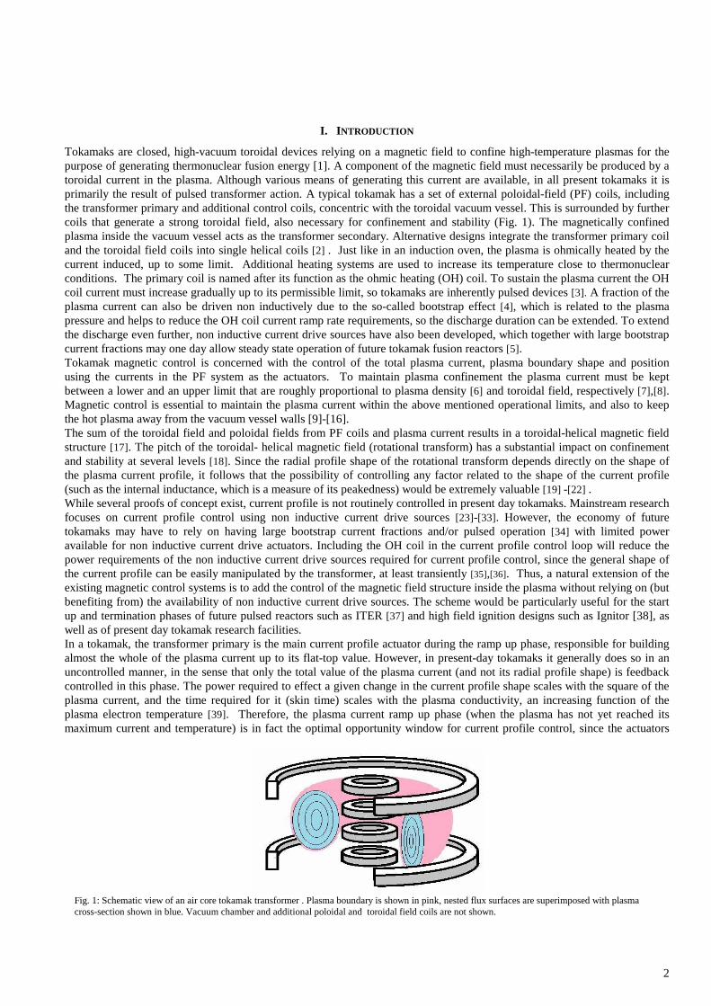
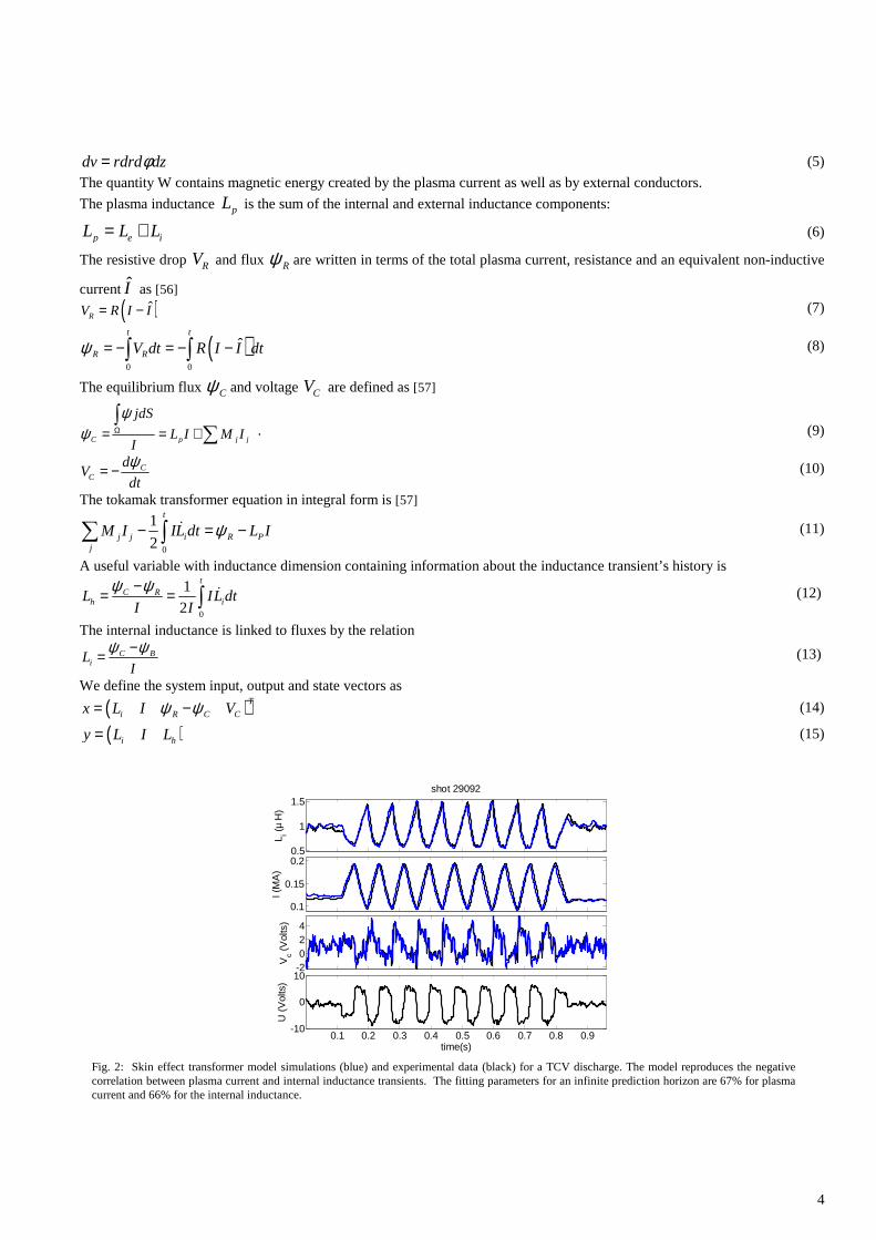
Fig. 2: Skin effect transformer model simulations (blue) and experimental data (black) for a TCV discharge. The model reproduces the negative correlation between plasma current and internal inductance transients. The fitting parameters for an infinite prediction horizon are 67% for plasma current and 66% for the internal inductance.
dv rdrd dzφ= (5)
The quantity W contains magnetic energy created by the plasma current as well as by external conductors.
The plasma inductance pL is the sum of the internal and external inductance components:
p e iL L L= + (6)
The resistive drop RV and flux Rψ are written in terms of the total plasma current, resistance and an equivalent non-inductive
currentI as [56]
( )ˆRV R I I= − (7)
( )0 0
ˆt t
R RV dt R I I dtψ = − = − −∫ ∫ (8)
The equilibrium flux Cψ and voltage CV are defined as [57]
C p j j
jdS
L I M II
ψψ Ω= = +
∫∑ . (9)
CC
dV
dt
ψ= − (10)
The tokamak transformer equation in integral form is [57]
0
1
2
t
j j i R Pj
M I IL dt L Iψ− = −∑ ∫ ɺ (11)
A useful variable with inductance dimension containing information about the inductance transient’s history is
0
1
2
tC R
h iL IL dtI I
ψ ψ−= = ∫ ɺ (12)
The internal inductance is linked to fluxes by the relation
C BiL
I
ψ ψ−= (13)
We define the system input, output and state vectors as
( )T
i R C Cx L I Vψ ψ= − (14)
( )i hy L I L= (15)
5
j jj
u M I=∑ ɺ (16)
For constant external and mutual inductances, the dynamics of the plasma current, internal inductance, flux and equilibrium loop voltage can be written in state space form as
( ) ( )( )
x f x g x u
y h x
= +
=
ɺ (17)
( )
( )( )
( )( )
( )( )( )( ) ( ) ( ) ( )
2 4
2
4 2
1
2 4
2 23 1 2 2 1 4 1
ˆ2
ˆ2
ˆ
ˆ1
e
R x I x
x
x R x If x
L x
R x I x
k x kx x R x I x x xω ω α β
− − − − = +
− − − − + − − −
(18)
( ) ( )
( )
11
2
11
21
22
e BR
e
e B
e
L T kx T k
L x
L T kx
L x
α
ωβ δω
= − − +
= + +
(19)
2
1
1 1
1( ) 0 0
T
B
e e
k T xg x
L x L x
ω −−= + +
(20)
31 2
2
( )T
xh x x x
x
= −
(21)
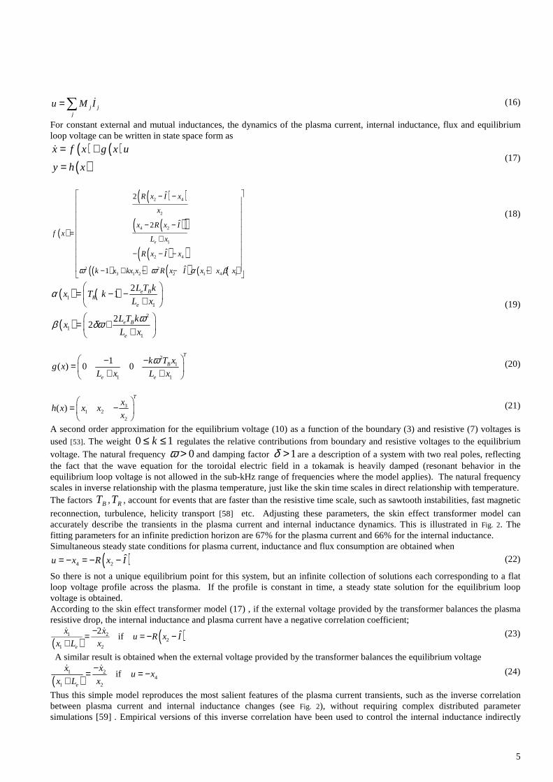
A second order approximation for the equilibrium voltage (10) as a function of the boundary (3) and resistive (7) voltages is used [53]. The weight 0 1k≤ ≤ regulates the relative contributions from boundary and resistive voltages to the equilibrium
voltage. The natural frequency 0ω > and damping factor 1δ > are a description of a system with two real poles, reflecting the fact that the wave equation for the toroidal electric field in a tokamak is heavily damped (resonant behavior in the equilibrium loop voltage is not allowed in the sub-kHz range of frequencies where the model applies). The natural frequency scales in inverse relationship with the plasma temperature, just like the skin time scales in direct relationship with temperature. The factors TB ,TR , account for events that are faster than the resistive time scale, such as sawtooth instabilities, fast magnetic
reconnection, turbulence, helicity transport [58] etc. Adjusting these parameters, the skin effect transformer model can accurately describe the transients in the plasma current and internal inductance dynamics. This is illustrated in Fig. 2. The fitting parameters for an infinite prediction horizon are 67% for the plasma current and 66% for the internal inductance. Simultaneous steady state conditions for plasma current, inductance and flux consumption are obtained when
( )4 2ˆu x R x I= − = − − (22)
So there is not a unique equilibrium point for this system, but an infinite collection of solutions each corresponding to a flat loop voltage profile across the plasma. If the profile is constant in time, a steady state solution for the equilibrium loop voltage is obtained. According to the skin effect transformer model (17) , if the external voltage provided by the transformer balances the plasma resistive drop, the internal inductance and plasma current have a negative correlation coefficient;
( ) ( )1 22
1 2
2 ˆife
x xu R x I
x L x
−= = − −+ɺ ɺ
(23)
A similar result is obtained when the external voltage provided by the transformer balances the equilibrium voltage
( )1 2
41 2
ife
x xu x
x L x
−= = −+ɺ ɺ
(24)
Thus this simple model reproduces the most salient features of the plasma current transients, such as the inverse correlation between plasma current and internal inductance changes (see Fig. 2), without requiring complex distributed parameter simulations [59] . Empirical versions of this inverse correlation have been used to control the internal inductance indirectly
6
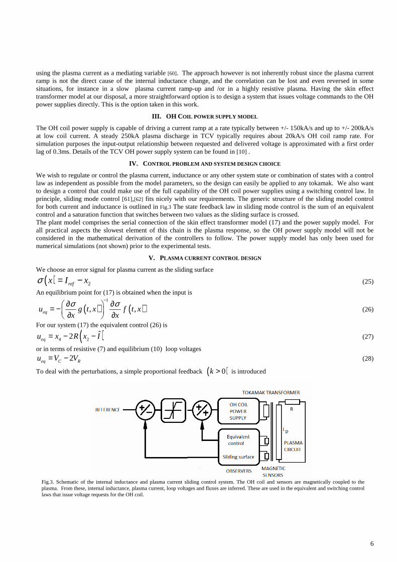
Fig.3. Schematic of the internal inductance and plasma current sliding control system. The OH coil and sensors are magnetically coupled to the plasma. From these, internal inductance, plasma current, loop voltages and fluxes are inferred. These are used in the equivalent and switching control laws that issue voltage requests for the OH coil.
using the plasma current as a mediating variable [60]. The approach however is not inherently robust since the plasma current ramp is not the direct cause of the internal inductance change, and the correlation can be lost and even reversed in some situations, for instance in a slow plasma current ramp-up and /or in a highly resistive plasma. Having the skin effect transformer model at our disposal, a more straightforward option is to design a system that issues voltage commands to the OH power supplies directly. This is the option taken in this work.
III. OH COIL POWER SUPPLY MODEL
The OH coil power supply is capable of driving a current ramp at a rate typically between +/- 150kA/s and up to +/- 200kA/s at low coil current. A steady 250kA plasma discharge in TCV typically requires about 20kA/s OH coil ramp rate. For simulation purposes the input-output relationship between requested and delivered voltage is approximated with a first order lag of 0.3ms. Details of the TCV OH power supply system can be found in [10] .
IV. CONTROL PROBLEM AND SYSTEM DESIGN CHOICE
We wish to regulate or control the plasma current, inductance or any other system state or combination of states with a control law as independent as possible from the model parameters, so the design can easily be applied to any tokamak. We also want to design a control that could make use of the full capability of the OH coil power supplies using a switching control law. In principle, sliding mode control [61],[62] fits nicely with our requirements. The generic structure of the sliding model control for both current and inductance is outlined in Fig.3 The state feedback law in sliding mode control is the sum of an equivalent control and a saturation function that switches between two values as the sliding surface is crossed. The plant model comprises the serial connection of the skin effect transformer model (17) and the power supply model. For all practical aspects the slowest element of this chain is the plasma response, so the OH power supply model will not be considered in the mathematical derivation of the controllers to follow. The power supply model has only been used for numerical simulations (not shown) prior to the experimental tests.
V. PLASMA CURRENT CONTROL DESIGN
We choose an error signal for plasma current as the sliding surface
( ) 2refx I xσ = − (25)
An equilibrium point for (17) is obtained when the input is
( ) ( )1
, ,equ g t x f t xx x
σ σ−∂ ∂ = − ∂ ∂ (26)
For our system (17) the equivalent control (26) is
( )4 2ˆ2equ x R x I= − − (27)
or in terms of resistive (7) and equilibrium (10) loop voltages
2eq C Ru V V= − (28)
To deal with the perturbations, a simple proportional feedback ( )0k > is introduced

7
( )su k xσ= −
(29)
A state feedback law is build from the required equivalent control input (27) and the feedback correction (29):
c eq su u u= + (30)
When the system (17) is subject to the state feedback (30), the reference for plasma current is approached asymptotically with speed
( ) ( )( )1
controle
s kf x g x u
x L x
σσ ∂= + = −∂ +
ɺ (31)
which can be regulated with the choice of k.
When actuator limits ,u u+ − are taken into consideration, the proportional feedback (29) takes the form of a relay function
( )( ) ( ) ( )
( )
,
,
,s
u x
u k x x x
u x
σ σσ σ σ σ
σ σ
+ +
− +
− −
>= − < < <
(32)
Ideally k should be infinitely large so the switching law (32) approaches a limiter function between the actuator limits
( )maxsu u sign σ= − (33)
Then, the fastest response time compatible with the actuator limits is achieved, and we have a sliding mode controller. As for the interaction with the actual plant, the required ramp rate for the transformer primary coil current 1I is obtained from cu as
11
cuI
M=ɺ (34)
and the voltage command to the OH coil is obtained as [10] 1
1 1 1 1 1 j jV L I R I M I= + −∑ɺ ɺ (35)
where 1jM are the mutual inductances between the OH coil and the rest of the PF coil systems and 1L , 1R are the OH coil
self inductance and resistance.
VI. INTERNAL INDUCTANCE CONTROL DESIGN
Both definitions (12),(13) give similar results and can indistinctly be used or combined to give a current profile related variable. To have some flexibility, we choose a generic sliding surface that is a linear combination of inductance and/or the inductance transient’s (12) history
( ) ( )1 3( )ref refi i h hx c L y c L yσ = − + − (36)
with 0, 0i hc c≥ > . The equivalent control for this is
( )( ) ( )( )
4 2
2 14 2
3
ˆ2
2 ˆ1
eq
ei
h
u x R x I
x L xcx R x I
c x
= − −
+ − + − −
(37)
We also choose a relay function
( )2 2
,
sgn ,
,
N
s
u
u x k x
u
σ σ
σ σ σ σσ σ
+ +
− +
− −
>= < < <
(38)
with N ∈ℤ , 0k > . The state feedback law (30) is build from (37) and (38).
The time derivative of the Lyapunov function [63] 2F σ= is negative when the system (17) is subject to the state feedback law given by (30) ,(37) ,(38)
( )
1
3 2 2
1
N
h
e
kc y x
L xσσ σ
−
= −+
ɺ (39)
This means that the control scheme has global asymptotic stability. Choosing N=1 the speed at which the reference is reached
is independent of the plasma current 2( )x value.
As in the previous section, the voltage request for the OH coil power supplies is obtained from (34) and (35).
8
The equivalent control (40) can be written in terms of the observers as
( ) ( )22 1 e ii
eq C R C Rh h
L Lcu V V V V
c L
+ = − + + −
(40)
For constant inductance ( )C RV V= both (27) and (40) are
eq Ru V≅ − (41)
so a fundamental purpose of the equivalent control is to compensate the resistive losses from the plasma.
VII. REAL TIME MEASUREMENTS AND OBSERVERS
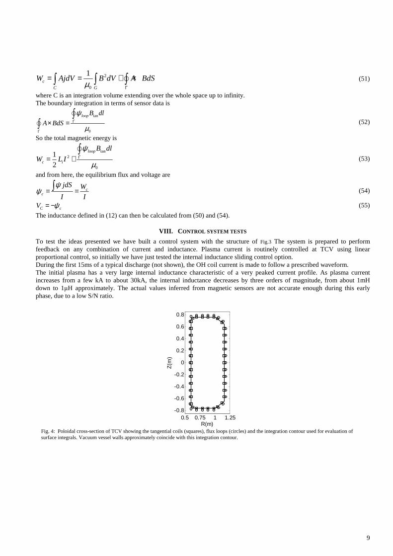
The internal inductance and loop voltages required for the controls designed in the previous sections are obtained indirectly using 80 of the magnetic sensors available on TCV [64] . These are a set of 38 small coils oriented tangentially to the vacuum vessel perimeter at the same toroidal location (giving the poloidal field component tangent to the vacuum vessel perimeter ), a set of 38 poloidal flux loops also placed at the vacuum vessel perimeter and concentric with the plasma current (used to obtain the poloidal field component perpendicular to the vacuum vessel perimeter), and a set of 4 toroidal flux loops that pick up different combinations of toroidal flux components resulting from plasma diamagnetism, toroidal field, and eddy currents in the vacuum vessel . The integration region is defined as the region bounded by the vacuum vessel. This will correspond to an axisymmetric region of volumeG delimited by an integration contourΓ which approximately coincides with the vacuum vessel perimeter (Fig. 4).
The information from magnetic sensors is combined to obtain the Shafranov parameter Λ and the poloidal beta using the formulas described in [65] . From these the normalized internal inductance is obtained as
li= 2 Λ − β
p( ) (42)
which is normalized to the machine major radius r0.
The internal inductance in SI units is
0 0
2i
i
r lL
µ= (43)
The plasma current is obtained from a boundary integration of the magnetic field
tan
0
B dl
Iµ
Γ=∫
(44)
The magnetic energy content inside the vacuum vessel walls is then trivially obtained as
W =1
2Li I
2 =µ0R0
4liI
2 (45)
This contains the magnetic energy due to the plasma current distribution and the magnetic energy due to the vacuum field enclosed by the integration contour. Two additional observers are required for the determination of the equivalent control laws (27),(40) , namely the plasma resistive drop (7) and equilibrium voltage (10)
( )2 4ˆ
R CV R x I V x= − = (46)
Poynting analysis gives the power flow through the vacuum vessel walls as
tanloopVI V B dlΓ
= ∫ (47)
so the ohmic power consumption in the plasma is
ohmP VI W= − ɺ (48)
thus, the resistive drop in the plasma is
ohmR
PV
I= (49)
and the resistive flux is obtained by time integration from the start of the discharge:
0
R RV dtψ = −∫ (50)
The total magnetic energy associated with the plasma current distribution in the entire space is
9
2
0
1c
C G
W AjdV B dV A BdSµ Γ
= = + ×∫ ∫ ∫ (51)
where C is an integration volume extending over the whole space up to infinity. The boundary integration in terms of sensor data is
tan
0
loop B dl
A BdS
ψ
µΓ
Γ
× =∫
∫
(52)
So the total magnetic energy is
tan2
0
1
2
loop
c i
B dl
W L I
ψ
µΓ= +∫
(53)
and from here, the equilibrium flux and voltage are
cc
jdS W
I I
ψψ = =∫ (54)
C cV ψ= − ɺ (55)
The inductance defined in (12) can then be calculated from (50) and (54).
VIII. CONTROL SYSTEM TESTS
To test the ideas presented we have built a control system with the structure of Fig.3 The system is prepared to perform feedback on any combination of current and inductance. Plasma current is routinely controlled at TCV using linear proportional control, so initially we have just tested the internal inductance sliding control option. During the first 15ms of a typical discharge (not shown), the OH coil current is made to follow a prescribed waveform. The initial plasma has a very large internal inductance characteristic of a very peaked current profile. As plasma current increases from a few kA to about 30kA, the internal inductance decreases by three orders of magnitude, from about 1mH down to 1µH approximately. The actual values inferred from magnetic sensors are not accurate enough during this early phase, due to a low S/N ratio.
0.5 0.75 1 1.25-0.8
-0.6
-0.4
-0.2
0
0.2
0.4
0.6
0.8
R(m)
Z(m
)
Fig. 4: Poloidal cross-section of TCV showing the tangential coils (squares), flux loops (circles) and the integration contour used for evaluation of surface integrals. Vacuum vessel walls approximately coincide with this integration contour.
10
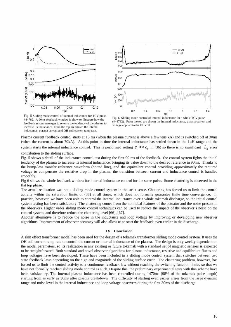
Plasma current feedback control starts at 15 ms (when the plasma current is above a few tens kA) and is switched off at 30ms (when the current is about 70kA). At this point in time the internal inductance has settled down in the 1µH range and the
system starts the internal inductance control. This is performed setting i hc c>> in (36) so there is no significant hL error
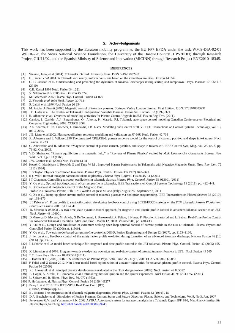
contribution to the sliding surface. Fig. 5 shows a detail of the inductance control test during the first 90 ms of the feedback. The control system fights the initial tendency of the plasma to increase its internal inductance, bringing its value down to the desired reference in 90ms. Thanks to the bump-less transfer reference waveform (dotted line), and the equivalent control providing approximately the required voltage to compensate the resistive drop in the plasma, the transition between current and inductance control is handled smoothly. Fig 6 shows the whole feedback window for internal inductance control for the same pulse. Some chattering is observed in the flat top phase. The actual realization was not a sliding mode control system in the strict sense. Chattering has forced us to limit the control activity within the saturation limits of (38) at all times, which does not formally guarantee finite time convergence. In practice, however, we have been able to control the internal inductance over a whole tokamak discharge, so the initial control system testing has been satisfactory. The chattering comes from the non ideal features of the actuator and the noise present in the observers. Higher order sliding mode control techniques can be used to reduce the impact of the observer’s noise on the control system, and therefore reduce the chattering level [66] ,[67]. Another alternative is to reduce the noise in the inductance and loop voltage by improving or developing new observer algorithms. Improvement of observer accuracy will also allow us to start the feedback even earlier in the discharge.
IX. Conclusion
A skin effect transformer model has been used for the design of a tokamak transformer sliding mode control system. It uses the OH coil current ramp rate to control the current or internal inductance of the plasma. The design is only weekly dependent on the model parameters, so its realization in any existing or future tokamak with a standard set of magnetic sensors is expected to be straightforward. Both standard and novel observer algorithms for plasma inductance, resistive and equilibrium fluxes and loop voltages have been developed. These have been included in a sliding mode control system that switches between two state feedback laws depending on the sign and magnitude of the sliding surface error. The chattering problem, however, has forced us to limit the control activity to a continuous feedback law without reaching the switching function limits, so that we have not formally reached sliding mode control as such. Despite this, the preliminary experimental tests with this scheme have been satisfactory. The internal plasma inductance has been controlled during 1470ms (98% of the tokamak pulse length) starting from as early as 30ms after plasma breakdown. The difficulty of starting even earlier arises from the large dynamic range and noise level in the internal inductance and loop voltage observers during the first 30ms of the discharge.
0.2
0.4
0.6
0.8
1
Li(µ
H)
Li varLi ref
0.1
0.2
0.3
Ip(M
A)
0.2 0.4 0.6 0.8 1 1.2 1.4
0
200
400
600
Voh
(V
)t(s)
Fig. 6. Sliding mode control of internal inductance for a whole TCV pulse (#44782). From the top are shown the internal inductance, plasma current and voltage applied to the OH coil.
Fig. 5 Sliding mode control of internal inductance for TCV pulse #44782. A 90ms feedback window is show to illustrate how the feedback system manages to reverse the tendency of the plasma to increase its inductance. From the top are shown the internal inductance, plasma current and OH coil current ramp rate.
11
X. Ackowledgements
This work has been supported by the Euratom mobility programme, the EU FP7 EFDA under the task WP09-DIA-02-01 WP III-2-c, the Swiss National Science Foundation, the University of the Basque Country (UPV/EHU) through Research Project GIU11/02, and the Spanish Ministry of Science and Innovation (MICINN) through Research Project ENE2010-18345.
REFERENCES
[1] Wesson, John; et al (2004). Tokamaks. Oxford University Press. ISBN 0-19-850922-7. [2] H. Tsutsui et al 2004. A tokamak with nearly uniform coil stress based on the virial theorem. Nucl. Fusion 44 954 [3] G. L. Jackson et al. Understanding and predicting the dynamics of tokamak discharges during startup and rampdown. Phys. Plasmas 17, 056116
(2010) [4] C.E. Kessel 1994 Nucl. Fusion 34 1221 [5] Y. Sakamoto et al 2005 Nucl. Fusion 45 574 [6] M. Greenwald 2002 Plasma Phys. Control. Fusion 44 R27 [7] Z. Yoshida et al 1990 Nucl. Fusion 30 762 [8] S. Lahiri et al 1996 Nucl. Fusion 36 254 [9] M. Ariola, A.Pironti.(2008) Magnetic control of tokamak plasmas. Springer Verlag London Limited. First Edition. ISBN: 9781848003231 [10] J.B. Lister et al. The Control of Tokamak Configuration Variable Plasmas. Fusion Sci. Technol. 32 (1997) 321. [11] R. Albanese, et al., Overview of modelling activities for Plasma Control Upgrade in JET, Fusion Eng. Des. (2011). [12] Garrido, I. Garrido, A.J. Barambones, O. Alkorta, P. Maseda, F.J. Tokamak state-space control modeling Canadian Conference on Electrical and
Computer Engineering, 2008. CCECE 2008. [13] A.S. Sharma, D.J.N. Limebeer, I. Jaimoukha, J.B. Lister. Modelling and Control of TCV. IEEE Transactions on Control Systems Technology, vol. 13,
no. 3, 2005. [14] J.B. Lister et al 2002. Plasma equilibrium response modelling and validation on JT-60U Nucl. Fusion 42 708 [15] R. Albanese and F. Villone 1998 The linearized CREATE-L plasma response model for the control of current, position and shape in tokamaks. Nucl.
Fusion 38 723 [16] G. Ambrosino and R. Albanese. “Magnetic control of plasma current, position, and shape in tokamaks”. IEEE Control Syst. Mag., vol. 25, no. 5, pp.
76-92, Oct. 2005. [17] V.D. Shafranov, “Plasma equilibrium in a magnetic field,” in “Reviews of Plasma Physics” (edited by M.A. Leontovich), Consultants Bureau, New
York, Vol. 2,p. 103 (1966). [18] J.W. Connor et al. (2004) Nucl. Fusion 44 R1 [19] Kessel C, Manickam J, Rewoldt G and Tang W M . Improved Plasma Performance in Tokamaks with Negative Magnetic Shear. Phys. Rev. Lett. 72
1212 (1994). [20] T S Taylor. Physics of advanced tokamaks. Plasma Phys. Control. Fusion 39 (1997) B47–B73. [21] R C Wolf. Internal transport barriers in tokamak plasmas. Plasma Phys. Control. Fusion 45 R1 (2003) [22] I T Chapman. Controlling sawtooth oscillations in tokamak plasmas Plasma Phys. Control. Fusion 53 013001 (2011) [23] Y. Ou et al., Optimal tracking control of current profile in tokamaks, IEEE Transactions on Control Systems Technology 19 (2011), pp. 432–441. [24] F. Bribiesca et al. Polytopic Control of the Magnetic Flux
Profile in a Tokamak Plasma 18th IFAC World Congress Milano (Italy) August 28 - September 2, 2011 [25] C. Xu et al., Ramp-up phase current profile control of tokamak plasmas via nonlinear programming, IEEE Transactions on Plasma Science 38 (2010),
pp. 163–173. [26] J I Paley et al . From profile to sawtooth control: developing feedback control using ECRH/ECCD systems on the TCV tokamak. Plasma Physics and
Controlled Fusion 2009 51 124041 [27] D. Moreau et al 2008 . A two-time-scale dynamic-model approach for magnetic and kinetic profile control in advanced tokamak scenarios on JET.
Nucl. Fusion 48 106001 [28] D.Mazon,a D. Moreau, M. Ariola, G De Tommasi, J. Brzozowski, R. Felton, I. Nunes, F. Piccolo, F. Sartori,d and L. Zabeo. Real-Time Profile Control
for Advanced Tokamak Operation. AIP Conf. Proc. March 12, 2008 Volume 988, pp. 430-433. [29] Y. Ou et al., Design and simulation of extremum-seeking open-loop optimal control of current profile in the DIII-D tokamak, Plasma Physics and
Controlled Fusion 50 (2008), p. 115001. [30] Y. Ou et al., Towards model-based current profile control at DIII-D, Fusion Engineering and Design 82 (2007), pp. 1153–1160. [31] J. Ferron et al., Feedback control of the safety factor profile evolution during formation of an advanced tokamak discharge, Nuclear Fusion 46 (10)
(2006), pp. 13–17. [32] L Laborde et al .A model-based technique for integrated real-time profile control in the JET tokamak. Plasma Phys. Control. Fusion 47 (2005) 155–183 [33] X. Litaudon et al 2003. Progress towards steady-state operation and real-time control of internal transport barriers in JET. Nucl. Fusion 43 565 [34] T.C. Luce Phys. Plasmas 18, 030501 (2011) [35] J. Hobirk et al. (2009). 36th EPS Conference on Plasma Phys. Sofia, June 29 - July 3, 2009 ECA Vol.33E, O-5.057 [36] F Felici and O Sauter 2012. Non-linear model-based optimization of actuator trajectories for tokamak plasma profile control. Plasma Phys. Control.
Fusion 54 025002 [37] R.J. Hawryluk et al .Principal physics developments evaluated in the ITER design review (2009). Nucl. Fusion 49 065012 [38] B. Coppi, A. Airoldi, F. Bombarda, et al. Optimal regimes for ignition and the Ignitor experiment. Nucl Fusion 41, 9: 1253-1257 (2001). [39] L. Spitzer and R. Hӓrm., Phys. Rev. 89, 977 (1953). [40] F. Hofmann et al, Plasma Phys. Control. Fusion 36 (1994) B277 [41] Paley J. et al 2010 17th IEEE-NPSS Real Time Conf. (RT)
(Lisbon, Portugal) pp 1–6 [42] B J Braams The interpretation of tokamak magnetic diagnostics. Plasma Phys. Control. Fusion 33 (1991) 715 [43] D.A. Batchelor et al . Simulation of Fusion Plasmas: Current Status and Future Direction. Plasma Science and Technology, Vol.9, No.3, Jun. 2007 [44] Pereverzev G.V. and Yushmanov P.N. 2002 ASTRA Automated system for transport analysis in a Tokamak Report IPP 5/98, Max-Planck-Institut für
Plasmaphysik,Garching. http://hdl.handle.net/10068/269743
12
[45] J.F. Artaud et al.The CRONOS suite of codes for integrated tokamak modelling. Nucl. Fusion 50 043001 ( 2010). [46] J.B. Lister et al.. Evolution of the DINA-CH tokamak full discharge simulator . Fusion Engineering and Design. Volume 74, Issues 1-4, November
2005, Pages 633-637. Proceedings of the 23rd Symposium of Fusion Technology - SOFT 23. [47] S.C. Jardin, S. Kaye, J. Menard, C. Kessel. Tokamak Simulation Code Modeling of NSTX .27th EPS Conference on Contr. Fusion and Plasma Phys.
Budapest, 12-16 June 2000 ECA Vol. 24B (2000) 1549-1552. [48] D.Moreau et al. Plasma models for real-time control of advanced tokamak scenarios. Nucl. Fusion 51 (2011) 063009 (14pp) [49] E Witrant, E Joffrin, S Brémond, G Giruzzi, D Mazon, O Barana and P Moreau. A control-oriented model of the current profile in tokamak plasma.
Plasma Phys. Control. Fusion Vol. 49 Num. 7 pp. 1075 (2007) [50] F. Felici, O. Sauter, S. Coda, B.P. Duval, T.P. Goodman,J-M. Moret,. J.I. Paley and the TCV Team.Real-time physics-model-based simulation of the
current density profile in tokamak plasmas. Nucl. Fusion 51 (2011) 083052 (19pp) [51] B.C.Kuo, F. Golnaraghi. (2009). Automatic control Systems. Ninth Edition. John Willey & sons. ISBN-13 978-0470-04896-2 [52] Karl J. Ǻström , Tore Hägglund. Advanced PID Control. Publisher: ISA ISBN/ID: 978-1-55617-942-6 [53] J.A.Romero et al. 2012 Development and validation of a tokamak skin effect transformer model. Nucl. Fusion 52 023019 [54] S.P. Hirshman and G.P. Neilson. External Inductance of an axisymmetric plasma. Phys.Fluids 29 (3) March 1986. [55] G.O. Ludwig and M.C.R. Andrade. External inductance of large ultralow aspect ratio tokamak plasmas. Physics of plasmas 5 (6). June 1998. [56] Ejima et al. Volt second analysis of D-III discharges. Nuclear Fusion Vol. 22. No 10 (1982) [57] J.A.Romero. (2010) Internal Inductance Dynamics in a tokamak. Nucl. Fusion 50 115002 [58] P. H. Diamond and M. Malkov. Dynamics of helicity transport and Taylor relaxation. Physics of plasmas Vol. 10. Num. 6 June 2003 [59] F. Imbeaux et al 2011. Current ramps in tokamaks: from present experiments to ITER scenarios. Nucl. Fusion 51 083026 [60] G.L. Jackson, T.A. Casper, T.C. Luce, D.A. Humphreys, J.R. Ferron, A.W. Hyatt, E.A. Lazarus, R.A. Moyer, T.W. Petrie, D.L. Rudakov and W.P.
West. ITER startup studies in the DIII-D tokamak. Nucl. Fusion 48 No 12 . Dec. 2008. [61] K. David Young, IEEE, Vadim I. Utkin, IEEE, and Umit Ozguner. A Control Engineer’s Guide to Sliding Mode Control. IEEE Transactions on
Control Systems Technology, 7, 3, May 1999, 328-342. [62] V.I. Utkin. Sliding mode design principles and application to electric drives. IEEE transactions on industrial electronics.Vol 40. N.1. pp. 23-36. Feb
1993 [63] M. Lazar, W.P.M.H. Heemels, A.R. Teel. Lyapunov Functions, Stability and Input-to-State Stability Subtleties for Discrete-time Discontinuous
Systems. IEEE Transcactions on automatic control Vol. 54 N. 10. pp. 2421 - 2425 September 2009. [64] J.-M. Moret, F. Buhlmann, D. Fasel, F. Hofmann, and G. Tonetti Magnetic measurements on the TCV Tokamak. REVIEW OF SCIENTIFIC
INSTRUMENTS VOLUME 69, NUMBER 6 JUNE 1998 . [65] V.D. Shafranov Determination of the parameters β and li in a Tokamak plasma for arbitrary shape of plasma pinch cross-section. Plasma Physics Vol.
13 (1971). Pp-757-762. [66] A. Levant. Sliding order and sliding accuracy in sliding mode control. Int. J. Control, 58(6). pp. 1247 (1993). [67] Bartolini, G., A. Ferrara and E. Usai (1998). Chattering avoidance by second-order sliding mode control. IEEE Transactions on Automatic Control,
43, 241-246.


1135- 9420