cerberc41v1v4 instal eng
TRANSCRIPT

8/6/2019 CerberC41V1V4 Instal Eng
http://slidepdf.com/reader/full/cerberc41v1v4-instal-eng 1/28
HOOKUP & PROGRAMMING BOOK
Cerber ® C41V4
Cerber ® C41V1
Document 10107/15.08.00 / Version 1
4 zone + 1 special zone control panels
with built-in vocal comunicator
8/6/2019 CerberC41V1V4 Instal Eng
http://slidepdf.com/reader/full/cerberc41v1v4-instal-eng 2/28
Cerber ® C41V1/Cerber ® C41V4HOOKUP INSTALLATION & PROGRAMMINGBOOK
2
Table of Contents
INTRODUCTION...........................................................................................................3Technical specifications ...................................................................................................... 4
Installing and commissioning ............................................................................................... 5
Connectors ........................................................................................................................... 7
OPERATING .................................................................................................................8Operating Codes .................................................................................................................. 8
Installer's Programming Code............................................................................................... 9
Arming .................................................................................................................................. 9
Other Arming Modes .......................................................................................................... 10
QUICK Arming .............................................................................................................. 10
�INSTANT STAY� Arming ............................................................................................. 10
�STAY� Arming............................................................................................................. 10
Disarming............................................................................................................................ 11
Other operating commands ............................................................................................... 11
Zone bypassing........................................................................................................... 11
System State Display .................................................................................................. 12
Alarm Memory Display ................................................................................................. 12
Door Chime On/Off ...................................................................................................... 13
Program/Modify User Codes ....................................................................................... 13Changing or Adding a Code .................................................................................. 14
Erasing a Code ...................................................................................................... 14
Dialing Stop......................................................................................................................... 14
VOCAL MESSAGES RECORDING/VERIFICATION ................................................... 14
SYSTEM PARAMETER PROGRAMMING ................................................................. 16Sections [01..07] - First ... Seventh Phone number .......................................................... 17
Section [08] - Message Duration/Dialing Attempts Number .............................................. 17
Section [09] - Zone Definitions .......................................................................................... 18
Section [10] - Key Zone Definitions................................................................................... 20
Section [11] - System Times .............................................................................................. 20
Section [12] - Installer's Code Changing............................................................................ 21
Section [13] - Programmable Output Options for PGM1, PGM2 ........................................ 21
Section [14] - Dialing Mode/Message Selection ................................................................ 22
PROGRAMMING FORM ............................................................................................ 24
Warning Limitations of this Alarm System .......................................................... 27
8/6/2019 CerberC41V1V4 Instal Eng
http://slidepdf.com/reader/full/cerberc41v1v4-instal-eng 3/28
Cerber ® C41V1/Cerber ® C41V4HOOKUP INSTALLATION & PROGRAMMINGBOOK
3
INTRODUCTION
Cerber C41V1/Cerber C41V4 are keypad operated burglary systems, with
built-in telephone dialer, alarm memory and 4 access codes.
Only one 30 second vocal message is available for Cerber C41V1 control
panel.
Four vocal messages, approx. 15 seconds each, are available for Cerber
C41V4 control panel.
The system facilities are keypad programmable. The central unit is RISC
microprocessor designed. The electric scheme includes an EEPROM
memory. Thus, the programmed parameters are retained even after all power was removed from the control panel.
FEATURES:
� 4 End-of-Line Resistor supervised zones; All zones are programmable as
Entry/Exit, Instant, Follower or 24 hour ;
� One Keyswitch/Tamper zone;
� Keypad programming;
� Master code and 3 user codes, all programmable;� Optional Ambush code (code 4);
� Quick arming, �Stay� arming, �Instant stay� arming;
� Optional Forced arming for Entry/Exit and Follower zones;
� Optional zone bypassing;
� Programmable Chime function;
� Programmable siren alarm type: Steady, Pulse or Silent;
� Programmable Entry delay, Exit delay;� Optional Keyswitch arming/disarming;
� 9 options for 2 programmable outputs which are: Latch alarm, Arming/
Disarming, Entry delay, Exit delay, System Trouble, Steady siren, Pulsing
siren, Silent alarm or Panic;
� First 9 alarm events which have occurred since the last arming are
displayed on keypad;
� 7 programmable phone numbers for one message transmission (Cerber
C41V1 control panel), respectively 4 messages (Cerber C41V4 controlpanel);

8/6/2019 CerberC41V1V4 Instal Eng
http://slidepdf.com/reader/full/cerberc41v1v4-instal-eng 4/28
Cerber ® C41V1/Cerber ® C41V4HOOKUP INSTALLATION & PROGRAMMINGBOOK
4
� Message duration and dialing attempts' number are programmable;
� Monitoring system state, battery state and AC power;
� EEPROM memory retains the programmed configuration even after all
power was removed from the control panel;
� Up to 4 keypads, 4 wire linked;
� Keypad tamper using microswitch;
� Individual state LEDs for each zone, indicating the alarm state;
� System state LEDs (READY, SYSTEM, ARMED).
TECHNICAL SPECIFICATIONS:
Power
� 12V/4Ah battery;
� 50mA stand-by current;
� typical 500mA power output on AUX power supply source
Inputs
� 4 fully programmable 2K2 EOL zones on board;
� 1 Keyswitch/tamper 2K2 EOL zones on board.
Outputs
� 2 "open-collector" outputs with negative trigger (NPN), max. 50mA;
• 1 "open-collector" siren output with positive trigger (PNP), typically 1A.
8/6/2019 CerberC41V1V4 Instal Eng
http://slidepdf.com/reader/full/cerberc41v1v4-instal-eng 5/28
Cerber ® C41V1/Cerber ® C41V4HOOKUP INSTALLATION & PROGRAMMINGBOOK
5
INSTALLING AND COMMISSIONING
PANEL MOUNTING
Select a dry location close to an unswitched AC source allowing groundconnection. If the system also sends vocal messages, the location must be
close to a telephone dose.
Remove the printed circuit board and mount the cabinet securely to the wall
using 4 screws. Mount the PCB into the cabinet. Pull all cables into the
cabinet and prepare them for connection.
KEYPAD MOUNTING
The keypad should be located close to the designed Entry/Exit door andmounted at a convenient height for all users.
Disassemble the keypad and mount the backplate on the wall. Pull the
keypad wiring inside the keypad and prepare it for connection.
WIRING
NOTE: Complete all wiring to the control panel before applying it to
battery or AC power.
Wiring should be made according to one of the next diagrams, depending onthe selected type: Cerber C41V1 or Cerber C41V4.

8/6/2019 CerberC41V1V4 Instal Eng
http://slidepdf.com/reader/full/cerberc41v1v4-instal-eng 6/28
Cerber ® C41V1/Cerber ® C41V4HOOKUP INSTALLATION & PROGRAMMINGBOOK
6
Cerber C41V1 control panel
GRN
EOL 2K2
EOL 2K2
YEL
A U X
1
,
.6 A
S I R E N
1 6 A
+
-
F1F2
DIF
PLAY RECORD
MIC
..
RE D BLACK
12V/4Ah
BAT T ER Y
GN D
+12Vdc K E Y P
A D
RESISTOR RESISTOR
SIREN OUTPUT
MAX 1A
NOTE
POLARITY
LINE
P H O N E
R ET U R N
K EY
N .C .
EOL 2K2
RESISTOR
Cerber C41V4 control panel
BATERIE
12V/4Ah
GRN
YEL
A U X
1 , 6
A
S I R E N Ã
1 , 6
A
+
-
F1F2
DIF
M 1 M 2 M 3 M4
R E C O R D
B U S Y
RE C
MIC
K E Y P
A D
EOL 2K2
RESISTOR
R ET U R N
K EY
N .C .
EOL 2K2
RESISTOR
EOL 2K2
RESISTOR
LINE
P H O N E
GN D
+12Vdc
SIREN OUTPUT
MAX 1A
NOTE
POLARITY
RE D BLACK

8/6/2019 CerberC41V1V4 Instal Eng
http://slidepdf.com/reader/full/cerberc41v1v4-instal-eng 7/28
Cerber ® C41V1/Cerber ® C41V4HOOKUP INSTALLATION & PROGRAMMINGBOOK
7
CONNECTORS
The following connectors are located on the PCB panel :
AUX - , AUX +
Connectors for auxiliary power supply.These terminals supply power for keypads, PIR detectors and other active
devices in the system.
The maximum load on these terminals cannot exceed 500mA. Observe
polarity!
YEL, GRN
Keypad communication.
PGM 1, PGM 2Programmable "open collector" outputs with negative trigger. The maximum
load on this terminals cannot exceed 100mA.
BELL +, BELL -
Siren output. "BELL+" is a positive trigger output (PNP).
The maximum load on these terminals cannot exceed 1A. Observe polar-
ity!
Z1, COM, Z2, Z3, COM, Z4Terminals for fully programmable zones.
If not used, the terminals will be closed with a 2K2 EOL resistor.
KEY
Terminals for special Keyswitch/Tamper zones.
If not used, the terminals will be closed with a 2K2 EOL resistor
SET
Phone set.
LINE
Phone line.
DIF
These terminals are used to connect a mini speaker in case of one's wish to
listen to the recorded messages.

8/6/2019 CerberC41V1V4 Instal Eng
http://slidepdf.com/reader/full/cerberc41v1v4-instal-eng 8/28
Cerber ® C41V1/Cerber ® C41V4HOOKUP INSTALLATION & PROGRAMMINGBOOK
8
COMMISSIONING
When finishing connections, first reset the system following the procedure
described bellow.
Reset to Default1. Disconnect power, both batteries and AC power.
2. Connect jumper JP10 (RESET) on PCB.
3. Power the panel and wait for 2 seconds..
4. If the system was reset to default, zone LEDs will blink successively, and
the green READY LED will be lit.
5. Disconnect power, both batteries and AC power.
6. Take jumper JP10 off (RESET) PCB.
7. Power the panel. From now on, the system parameters are set to default
and the system is disarmed.
OPERATION
Zone LEDs
�SYSTEM� LED
�READY� LED
�ARMED� LED
System operation is done using the keypad and LEDs' indications. The
keypad has 4 zone LEDs and 3 state LEDs: READY, SYSTEM, ARMED.
LEDs' indications will be detailed throughout this manual.
OPERATING CODES
There are 4 programmable operating codes in the system.
Code 1- Master Code programmed with "1234" value by default. Using the
Master code one can operate the system and program the other user codes.
Code 4 - "Ambush Code", not programmed by default.
If the panel is connected to the phone line, when disarming - using thisparticular code - the panel will transmit a phone message to Cerber C41V1
control panel.
8/6/2019 CerberC41V1V4 Instal Eng
http://slidepdf.com/reader/full/cerberc41v1v4-instal-eng 9/28
Cerber ® C41V1/Cerber ® C41V4HOOKUP INSTALLATION & PROGRAMMINGBOOK
9
For Cerber C41V4 control panel, using the Ambush code when disarming,
the panel will transmit a special phone message meaning the system was
disarmed under threat.
Code modifying , including Master code, is made by [*][7][�Master Code�]
command.
INSTALLER'S CODE
The default Installer's Code is �0269�.
This code achieves parameter programming by [*][8][Installer's code]
command.
The installer should change this code after mounting the system!
ARMING
Before arming the system, make sure that all protected doors and windows
have been closed.
If the �SYSTEM� LED is lit, check the following:
- the alarm memory ([*][5] command). If there are alarms in the memory, it
will be cleared when arming the system.
- bypassed zones ([*][3] [Access code] command). Ensure that each zone
displayed as being bypassed is intentionally bypassed.- system trouble ([*][4] command). If there are troubles with the battery or the
AC power, fix them before arming.
If "READY" LED is not lit, then one or more zones are open. One cannot
arm the system if the system is not ready meaning that "READY" LED
should be lit.
To arm the system, introduce a 4 digit access code. When pressing each
key, the keypad buzzer will sound a short beep.
After pressing the access code, the "ARMED" LED will turn on and thekeypad buzzer will sound 6 beeps.
If the access code is not correct, the keypad buzzer will sound a long beep.
Press the [#] key and then press the access code again.
After pressing the access code and the "ARMED" LED was lit, exit the
protected area through the Entry/Exit zone, before the Exit time was over.
After the Exit time was over, all LEDs will be off, except the "ARMED" LED.
The default Exit time is 120 seconds.
8/6/2019 CerberC41V1V4 Instal Eng
http://slidepdf.com/reader/full/cerberc41v1v4-instal-eng 10/28
Cerber ® C41V1/Cerber ® C41V4HOOKUP INSTALLATION & PROGRAMMINGBOOK
10
OTHER ARMING MODES
QUICK ARMING
[*] [0]
This function will be used by someone who doesn't own an access code.
Arming will be made by pressing the sequence [*][0]. Next, the user should
leave the protected area before Exit time was over. After the Exit time was
over, the whole system is armed and the "ARMED" LED will stay lit.
�INSTANT STAY� ARMING
[*] [1] [ACCESS CODE]
This arming mode is used for perimeter protection. Thus, the user can stay
inside the protected area (i.e.: arming the panel at night while staying home).
After pressing the access code, the system automatically bypasses zones
defined with "STAY" attribute. That is why the yellow "SYSTEM" LED will
be lit. After the Exit time, all the Delayed zones will become Instant and
they will trigger alarm the very moment they are opened.
The red "ARMED" LED will blink indicating that the Delayed zones are
Instant now.
�STAY� ARMING
[*] [2] [ACCESS CODE]
This arming mode is also used for perimeter protection. This time the user
also stays inside the protected area, but is allowed access through the
Delayed zones.
After pressing the access code the system automatically bypasses the
zones defined with "STAY" attribute. That is why the yellow "SYSTEM"
LED will be lit. After the Exit time was over, the whole system is armed and
the "ARMED" LED will stay lit.
NOTE:
The Entry/Exit and the Follower zones can be programmed for Forced
arming. That means these zones will be bypassed until their closing, after
the Exit time was over.
The Forced arming option is useful if, for example, going out of the system is
done through a door with magnetic contact, which is connected to an Entry/
Exit zone. At the same time the door is supervised by a PIR detector,connected to a Follower zone. If the Exit time is shorter than PIR detector
stabilization time, then the 2 zones will be programmed with Forced arming

8/6/2019 CerberC41V1V4 Instal Eng
http://slidepdf.com/reader/full/cerberc41v1v4-instal-eng 11/28
Cerber ® C41V1/Cerber ® C41V4HOOKUP INSTALLATION & PROGRAMMINGBOOK
11
in order to be bypassed when arming.So, bypassing cancellation will be done
when the zones are closed (that is when closing the door and leaving the
protected area).
DISARMING
One can only enter the protected area through an Entry/Exit zone. When
opening this zone, Entry time will begin counting.
During Entry time keypad buzzer will sound a continuous beep indicating that
the system should be disarmed.
Press one of the access codes. If wrong press [#] key and press the code
again. The "ARMED" LED will turn off and so will the buzzer.
If the system is not disarmed during Entry time, the panel will alarm. To
modify the Entry time see PROGRAMMING chapter, section 11.
OTHER OPERATING COMMANDS
ZONE BYPASSING
[*] [3] [ACCESS CODE]
Zone bypassing can only be done when the system is disarmed.
The initiating devices from a bypassed zone will not be considered by the
panel. Zone bypassing is used when access is needed in that particular zone
even if the system is armed. Zone bypassing is also used when some
initiating devices or wires are damaged and restoring is not immediately
possible .
Arming can be done with one or more bypassed zones, even if these ones
are open.
While the system is disarmed, press [*] [3] [User code] to display the
bypassed zones. The "SYSTEM" LED will blink and the corresponding zone
LEDs will be lit.
To bypass a zone press the corresponding digit and the corresponding LED
will turn ON. To cancel a zone bypassing press the corresponding digit, and
the corresponding LED will turn OFF.
Exit bypassing mode by pressing [#].
NOTE: When disarming the system, the bypassed zones will be cleared.
8/6/2019 CerberC41V1V4 Instal Eng
http://slidepdf.com/reader/full/cerberc41v1v4-instal-eng 12/28
Cerber ® C41V1/Cerber ® C41V4HOOKUP INSTALLATION & PROGRAMMINGBOOK
12
S YSTEM STATE DISPLAY
[*] [4]
The alarm system is monitoring some trouble conditions. If one of these
conditions occurs, the "SYSTEM" LED will turn ON.To display these conditions press [*] [4]. The conditions will be displayed on
zone LEDs as follows:
Zone 1 LED Low Battery: if the battery is disconnected or LOW, this LED
is lit. The LED will turn OFF in 8 seconds after restoring the battery trouble.
Zone 2 LED AC Power Loss: if AC power is OFF or the transformer is burnt
this LED is lit. The LED is also lit if AC power circuit fuse is burnt. The LED
will turn OFF instantly after restoring AC power trouble.
To exit this mode press [#] key.
ALARM MEMORY DISPLAY
[*] [5]
The alarms produced while last arming are memorized. To display the
alarmed zones press [*] [5].
"SYSTEM" LED will blink and so will the LEDs of the alarmed zones.
One can press the keys from 1 to 9 in order to visualize the first 9 alarm
events during the last arming of the panel. Pressing the key [1] the first zone
alarmed will be shown , while pressing the key [9] the latest alarmed zone
will be shown.
Pressing the key [0] one can see all the alarmed zones simultaneously. All
the corresponding zone LEDs will blink.
To exit this display mode press [#] key.
The alarm memory will clear while arming the panel again .
DOOR CHIME ON /OFF
[*] [6]
The Door Chime feature makes the keypad buzzer to sound 6 short beeps
whenever a delayed zone is activated. The feature is useful if the Delayed
doors are out of view and the user desires an indication of when the door
zones are opened.

8/6/2019 CerberC41V1V4 Instal Eng
http://slidepdf.com/reader/full/cerberc41v1v4-instal-eng 13/28
Cerber ® C41V1/Cerber ® C41V4HOOKUP INSTALLATION & PROGRAMMINGBOOK
13
The Door Chime feature works only if the the system is disarmed.
The feature may only be turned on/off also while the system is disarmed. To
turn the feature on/off enter [*] [6] command. If the feature is being turned
ON, the keypad buzzer will beep 3 times. If the feature is being turned OFF,
the keypad buzzer will sound only one long beep.
PROGRAM /MODIFY USER CODES
[*] [7] [MASTER CODE]
The [*] [7] [Master Code] command allows the user to modify all user codes
but the Installer's Code.
Enter [*] [7] [Master Code]
The LEDs �READY�, �ARMED� and �SYSTEM� will blink.The lit zone LEDs will indicate which codes are programmed. By default,
zone 1 LED will be ON indicating the Master code is only pre-programmed
(Master code is code 1).
From this moment on the codes are to be modified as follows:
Changing or Adding a Code
In order to change or add the 1 to 4 access codes, enter the number of the
code to be changed/added.
The corresponding zone LED will blink and the keypad buzzer will sound 3
beeps. Enter the new access code (4 digits). Do not press [*] while enter-
ing the code.
After introducing the code, the keypad buzzer will sound 6 beeps and the
corresponding zone LED will be ON.
To edit another code, key another order number in and replay the procedure.
Thus, all the desired codes will be changed.
Erasing a Code After introducing the number of the code to be erased, the corresponding
zone LED will blink and the keypad buzzer will sound 3 beeps. To erase the
code press [****].
NOTE: Do not erase Master Code! If, by mistake the Mater Code is erased,
reset system programming to the factory default settings. (see Commission-
ing).
During the Program/Modify User code mode, "READY", "SYSTEM" and
"ARMED" LEDs will blink continuously and zone LEDs will indicate:
8/6/2019 CerberC41V1V4 Instal Eng
http://slidepdf.com/reader/full/cerberc41v1v4-instal-eng 14/28
Cerber ® C41V1/Cerber ® C41V4HOOKUP INSTALLATION & PROGRAMMINGBOOK
14
Zone LED The access code is:
OFF not programmed
ON programmed
blinking programming in progress After making all the desired changes, exit this mode by pressing [#] key.
DIALING STOP
[*] [9] [MASTER CODE]
Dialing stop can only be done when the system is disarmed.
Therefore, if an alarm occurs in armed mode and the dialer starts phone
communication,in order to stop dialing enter a valid user code for disarming,
then enter the sequence [*] [9] [Master Code].
VOCAL MESSAGE RECORDING/CHECKING
CERBER C41V1 CONTROL PANEL
For vocal message recording follow the procedure described bellow:
1. Open the control panel cover.
2. Keep RECORD button pressed, placed top-right on the PCB.3. After the red LED turned ON, holding RECORD button pressed, say the
message directly into the microphone. The message must not exceed 30
seconds.
NOTE: If the message exceeds 30 seconds, the LED turns OFF and the
recording is automatically stopped. In this case, shorten the message and
repeat the recording.
4. To stop the recording, release RECORD button.
For local checking of recorded vocal messages follow the procedure de-
scribed bellow:
1. Connect a temporary mini-speaker (min. 8ohm impedance) to the DIF
terminals.
2. Press PLAY button, placed near the RECORD button, and listen to the
message.
3. Disconnect the speaker.
4. Close the control panel cover.

8/6/2019 CerberC41V1V4 Instal Eng
http://slidepdf.com/reader/full/cerberc41v1v4-instal-eng 15/28
Cerber ® C41V1/Cerber ® C41V4HOOKUP INSTALLATION & PROGRAMMINGBOOK
15
CERBER C41V4 CONTROL PANEL (4 VOICE MESSAGES)
For vocal messages recording follow the procedure described bellow:
1. Open the control panel cover.
2. Connect jumper REC on PCB. The green "RECORD" LED will turn ON.3. Record the first message keeping M1button pressed .
4. After the red BUSY LED turned ON, keeping M1 button pressed, say the
message directly into the microphone. The message does not have to
exceed 15 seconds.
NOTE: If the message exceeds 15 seconds, the BUSY LED turns OFF and
the recording will be automatically stopped. In this case, shorten the
message and repeat the recording.
5. To stop the recording, release M1 button.6. To record the messages 2, 3 and 4, repeat steps 3 and 4 using buttons
M2, M3 and M4, respectively.
7. Disconnect REC jumper .
Each event is assigned a certain message as follows:
Message 1 - One of zones 1-4 is activated
Message 2 - Panic from the keypad
Message 3 - AC Loss
Message 4 - Ambush condition
For local checking of recorded vocal messages follow the procedure de-
scribed bellow:
1. Connect a temporary mini-speaker (min. 8Ohm impedance) to the DIF
terminals.
2. Press one of M1-M4 buttons and listen to the respective message. BUSY
LED is ON during the message playback.
3. Disconnect the speaker.
4. Close the control panel cover.

8/6/2019 CerberC41V1V4 Instal Eng
http://slidepdf.com/reader/full/cerberc41v1v4-instal-eng 16/28
Cerber ® C41V1/Cerber ® C41V4HOOKUP INSTALLATION & PROGRAMMINGBOOK
16
SYSTEM PARAMETER PROGRAMMING
ENTERING THE PROGRAMMING MODE OF S YSTEM PARAMETERS
[ * ] [ 8 ] [INSTALLER'S CODE]
Entering the programming mode of system parameters is achieved by
[*][8][Installer's Code] command, only in disarmed mode. The system
programming options are explained bellow.
The default Installer's Code is [0269] and it is strongly recommended to be
changed after installing the alarm system.
After pressing [*][8][Installer's Code], the keypad buzzer will sound 3 beeps,
and the LEDs will display as follows:
LED LED STATE
READY OFF
SYSTEM Blinking
ARMED ON
Zone LEDs OFF
Now you have just entered the system parameter programming mode.
To leave the programming mode press [#] key.
System parameters are grouped in sections counted from 01 to 14. To enter
each section press the 2 corresponding digits.
After entering the 2 digits, the keypad buzzer will sound 3 beeps an the
LEDs will display as follows:
LED LED STATE
READY ON
SYSTEM Blinking ARMED ON
Zone LEDs OFF
This moment you are inside the chosen section.
To leave the section press [#] key.
Certain programming entries may require entry of data in HEX. To enter data
in HEX format, first press the [*] key followed by a number according to the
data inthe table bellow:
8/6/2019 CerberC41V1V4 Instal Eng
http://slidepdf.com/reader/full/cerberc41v1v4-instal-eng 17/28
Cerber ® C41V1/Cerber ® C41V4HOOKUP INSTALLATION & PROGRAMMINGBOOK
17
HEX number
A Enter [*][0]
B Enter [*][1]
C Enter [*][2]
D Enter [*][3]
E Enter [*][4]
F Enter [*][5]
Note that after pressing the [*] key, �READY� LED will blink and after
entering the decimal digit , the LED will stay lit.
PROGRAMMING SECTIONS
SECTIONS [01..07] - FIRST ... SEVENTH PHONE NUMBER
These are the phone numbers to which the control panel will send the vocal
messages by phone line.
Each phone number will be entered like a number dialed on a key phone. The
maximum number of digits is 15.
After entering the last digit of the phone number, press [#] key.
A 2 second pause for number dialing can be added by entering [*][3].
To clear the phone number enter [*][5][#].
Note: In order to enter 01-07 sections, [*] [8] [Master code] command may
be used.
SECTION [08] - MESSAGE DURATION /DIALING ATTEMPT NUMBER
Enter 2 groups of 3 digits each (001..255).
The first group of 3 digits represents message duration in seconds. The
default duration is [030] seconds.
The second group of 3 digits represents the dialing attempt number (for each
programmed phone number). The default dialing attempt number is [002].
SECTION [09] - ZONE DEFINITIONS
To programm the characteristics of zones 1-4 enter 4 groups of 2 digits.
The first digit of each group represents the zone type and can have
the value of: 0, 1, 2 or 3.

8/6/2019 CerberC41V1V4 Instal Eng
http://slidepdf.com/reader/full/cerberc41v1v4-instal-eng 18/28
Cerber ® C41V1/Cerber ® C41V4HOOKUP INSTALLATION & PROGRAMMINGBOOK
18
[ 0 ] E NTRY /E XIT ZONE (DELAYED ZONE )
An Entry/Exit zone is usually used for Entry/Exit doors. The Exit Delay starts
when the system is armed. The zone may be opened and closed during the
delay without causing an alarm.
When the Exit Delay expires, zone opening will start the Entry Delay. Duringthe Entry Delay, the keypad buzzer will sound continuously to indicate that
the system should be disarmed. If the system is disarmed before the Entry
Delay expired, no alarm will be generated.
Entry and Exit Delay times may be independently programmed for 1 to 255
seconds in section 11. The default settings are 120 seconds for the Exit
Delay and 30 seconds for the Entry Delay.
This zone type can be programmed for Forced arming.
[ 1 ] I NSTANT ZONE
Instant zones are normally used for door and window contacts. Instant zones
are disabled during Exit Delay, but will generate an instant alarm if opened
after Exit Delay expired.
The Exit Delay is the same as for Delayed zones and is 120 seconds by
default.
[ 2 ] F OLLOWER ZONE
The Follower zones are used with interior motion detectors and follow thestandard Exit Delay. If entering the system is done through a Delayed zone,
then the Follower zone will have the standard Entry Delay. If entering the
system is done through a Follower zone without coming through a Delayed
zone, an alarm will be generated.
This zone type can be programmed for Forced arming.
[ 4 ] 24-H OUR ZONE
The 24-hour zones are permanently active. If such a zone is tripped, an alarm
will be generated even if the system is disarmed.The second digit of each group represents the alarm type. There are
six alarm types:
[ 0 ] STEADY
Send an alarm message and the siren will be enabled.
[ 1 ] PULSE
Send an alarm message and the siren will be enabled in pulse.
After an pulsing alarm occurring all the other audible alarms will be pulsingalarms, until the siren will be stopped.

8/6/2019 CerberC41V1V4 Instal Eng
http://slidepdf.com/reader/full/cerberc41v1v4-instal-eng 19/28
Cerber ® C41V1/Cerber ® C41V4HOOKUP INSTALLATION & PROGRAMMINGBOOK
19
[ 2 ] SILENT
Sends an alarm message and the siren will be not enabled.
[ 4 ] STEADY ALARM AND FORCED ARMING
An alarm message will be send by phone line and the siren will be enabled.The system can be armed even if this zone is not secured.
[ 5 ] PULSED ALARM AND FORCED ARMING
An alarm message will be send by phone line and the siren will be enabled in
pulse. The system can be armed even if this zone is not secured.
[ 6 ] SILENT ALARM AND FORCED ARMING
An alarm message will be send by phone line and the siren will be not
enabled. The system can be armed even if this zone is not secured.
NOTE: The forced arming alarm type is only available for Entry/Exit and
Follower zones.
Example: Zones are to be programmed this way:
Zone 1 - Entry/Exit zone with steady alarm
Zone 2 - Follower zone with steady alarm
Zone 3 - Instant zone with steady alarm
Zone 4 - 24 Hour zone with pulse alarm
After entering the section by pressing [0] [9], enter the sequence:
[0][0] [2][0] [1][0] [3][1]
After each of the 2 digits, the keypad buzzer will sound 3 beeps. After
entering the last 2 digits, the keypad buzzer will sound 6 beeps and exit the
section 09 waiting for a new command.
SECTION [10] - KEY ZONE DEFINITIONS
Enter 2 digits in order to determine "KEY" zone features.
The first digit represents the "KEY" zone type and can be:
[ 3 ] PANIC OR TAMPER ZONE
The Panic zone is permanently active. If such a zone is tripped, an alarm will
be generated even if the system is disarmed.
[ 4 ] ARMING /DISARMING BY KEY
The system can be armed/disarmed by areturn key with NC contact. If the
system is armed then, when zone is opened, the system will be disarmed. If
the siren is enabled, then when zone is opened, the siren will be stopped.

8/6/2019 CerberC41V1V4 Instal Eng
http://slidepdf.com/reader/full/cerberc41v1v4-instal-eng 20/28
The second digit represents the alarm type for panic or tamper zone
and the alarm type as well when [*] and [#] keys are pressed simulta-
neously (see section 09).
SECTION [11] - S YSTEM TIMES
Enter 3 groups of 3 digits each (001 to 255 seconds), to establish the three
system delays:
Entry Delay
The Entry Delay determines the lapse of time allowed between the activation
of an Entry/Exit zone and system disarming. If the system is not disarmed
during this delay, an alarm will be generated. The default Entry Delay is 30
seconds.
Exit Delay
The Exit Delay determines the lapse of time allowed between entering an
access code to arm the system, and the activation of an Entry/Exit zone to
exit the protected area. The default Exit Delay is 120 seconds.
Bell cut-off time
The bell cut-off time represents how long the siren will be enabled when an
alarm occurs. When an alarm occurs, the siren will sound until this period of
time is exceeded or an access code is entered.
Example: These times are to be programed this way:
Entry time - 10 seconds
Exit time - 60 seconds
Bell cut-off time - 3 minutes
After entering the section by pressing [1][1], enter the sequence:
[0][1][0] [0][6][0] [0][0][3]
After each of the 3 digits, the keypad buzzer will sound 3 beeps. After entering the last 3 digits, the keypad buzzer will sound 6 beeps and exit the
section 11 waiting for a new command.
SECTION [12] INSTALLER'S CODE CHANGING
The default value for the Installer's Code is [0269]. It is strongly recom-
mended to change this code after completing the installation of the alarm
system. Keep the new code in a safe place.
Enter 4 digits [X] [X] [X] [X]. Next, the keypad buzzer will sound 6 beeps andwill exit section 12 waiting for a new command.
8/6/2019 CerberC41V1V4 Instal Eng
http://slidepdf.com/reader/full/cerberc41v1v4-instal-eng 21/28
Cerber ® C41V1/Cerber ® C41V4HOOKUP INSTALLATION & PROGRAMMINGBOOK
21
SECTION [13] PROGRAMMABLE OUTPUT OPTIONS FOR PGM1, PGM2
Enter 2 digits.
The first digit refers to PGM1 and the second one refers to PGM2, and
they stand for:
[0] LATCH ON ALARM
The output goes to ground in alarm circumstances, and is shut OFF when
disarming.
[1] S YSTEM STATE FOLLOW
The output goes to ground when arming, and is shut OFF when disarming.
[2] ENTRY DELAY
The output goes to ground during the Entry Delay.
[3] EXIT DELAY
The output goes to ground during the Exit Delay.
[4] TROUBLE
The output goes to ground while there is a trouble in the system (AC power
loss, low battery, unsuccessful communication attempt).
[5] CONTINUOUS SIREN
The output goes to ground while the siren is sounding continuously.[6] PULSING SIREN
The output goes to ground while the siren is sounding in pulses.
[7] SILENT SIREN
The output goes to ground while any silent alarm is enabled.
[8] PANIC
The output goes to ground when panic feature is activated (panic zone or by
simultaneously pressing [*]+[#] keys).
SECTION [14] DIALING MODE /MESSAGE SELECTION
Enter 2 digits.
The first digit represents:
0 = Pulse dialing
1 = DTMF dialing
8/6/2019 CerberC41V1V4 Instal Eng
http://slidepdf.com/reader/full/cerberc41v1v4-instal-eng 22/28
Cerber ® C41V1/Cerber ® C41V4HOOKUP INSTALLATION & PROGRAMMINGBOOK
22
When a phone line transmission is initiated within the first 5 seconds, the
control panel checks up the presence of the free line tone. If the line tone is
detected, then the control panel dials immediately the programmed phone
number. If after 5 seconds the line tone is not detected, the control panel will
still dial the programmed phone number.
The second hex digit represents:
0 = the vocal message is not sent
Cerber C41V1 control panel
1 = sends the alarm message when one of zones 1-4 is tripped
2 = sends the alarm message when Panic is activated from the keypad
4 = sends the alarm message when AC Loss
8 = sends the alarm message when Ambush
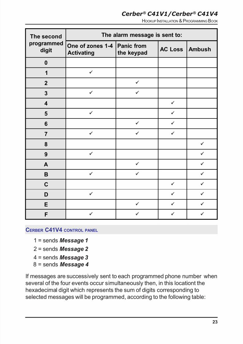
If the message is sent when several of the four events occur simultaneously
then, in this location the hexadecimal digit which represents the sum of digits
corresponding to the selected messages will be programmed, according to
following table:
8/6/2019 CerberC41V1V4 Instal Eng
http://slidepdf.com/reader/full/cerberc41v1v4-instal-eng 23/28
Cerber ® C41V1/Cerber ® C41V4HOOKUP INSTALLATION & PROGRAMMINGBOOK
23
The second
programmed
digit
The alarm message is sent to:
One of zones 1-4
Activating
Panic from
the keypadAC Loss Ambush
0
1 ü
2 ü
3 ü ü
4 ü
5 ü ü
6 ü ü
7 ü ü ü
8 ü
9 ü ü
A ü ü
B ü ü ü
C ü ü
D ü ü ü
E ü ü ü
F ü ü ü ü
CERBER C41V4 CONTROL PANEL
1 = sends Message 12 = sends Message 2
4 = sends Message 3
8 = sends Message 4
If messages are successively sent to each programmed phone number when
several of the four events occur simultaneously then, in this locationt the
hexadecimal digit which represents the sum of digits corresponding to
selected messages will be programmed, according to the following table:

8/6/2019 CerberC41V1V4 Instal Eng
http://slidepdf.com/reader/full/cerberc41v1v4-instal-eng 24/28
Cerber ® C41V1/Cerber ® C41V4HOOKUP INSTALLATION & PROGRAMMINGBOOK
24
The second
programmed
digit
It is sent a succession consists of:
Message 1 Message 2 Message 3 Message 4
01 ü
2 ü
3 ü ü
4 ü
5 ü ü
6 ü ü7 ü ü ü
8 ü
9 ü ü
A ü ü
B ü ü ü
C ü üD ü ü ü
E ü ü ü
F ü ü ü ü
PROGRAMMING FORM
[01] FIRST PHONE NUMBER PROGRAMMING
Default: not programmed [ ] [ ] [ ] [ ] [ ] [ ] [ ] [ ] [ ] [ ] [ ] [ ] [ ] [ ] [ ]
[02] SECOND PHONE NUMBER PROGRAMMING
Default: not programmed [ ] [ ] [ ] [ ] [ ] [ ] [ ] [ ] [ ] [ ] [ ] [ ] [ ] [ ] [ ]
[03] THIRD PHONE NUMBER PROGRAMMING
Default: not programmed [ ] [ ] [ ] [ ] [ ] [ ] [ ] [ ] [ ] [ ] [ ] [ ] [ ] [ ] [ ]

8/6/2019 CerberC41V1V4 Instal Eng
http://slidepdf.com/reader/full/cerberc41v1v4-instal-eng 25/28
Cerber ® C41V1/Cerber ® C41V4HOOKUP INSTALLATION & PROGRAMMINGBOOK
25
[04] FOURTH PHONE NUMBER PROGRAMMING
Default: not programmed [ ] [ ] [ ] [ ] [ ] [ ] [ ] [ ] [ ] [ ] [ ] [ ] [ ] [ ] [ ]
[05] FIFTH PHONE NUMBER PROGRAMMING
Default: not programmed [ ] [ ] [ ] [ ] [ ] [ ] [ ] [ ] [ ] [ ] [ ] [ ] [ ] [ ] [ ]
[06] SIXTH PHONE NUMBER PROGRAMMING
Default: not programmed [ ] [ ] [ ] [ ] [ ] [ ] [ ] [ ] [ ] [ ] [ ] [ ] [ ] [ ] [ ]
[07] SEVENTH PHONE NUMBER PROGRAMMING
Default: not programmed [ ] [ ] [ ] [ ] [ ] [ ] [ ] [ ] [ ] [ ] [ ] [ ] [ ] [ ] [ ]
[08] MESSAGE DURATION /DIALING ATTEMPT NUMBER PROGRAMMING
Default: [ ] [ ] [ ] [ ] [ ] [ ]
[09] ZONE DEFINITIONS
Default Digit 1 Digit 2
[0] [0] [ ] [ ] Zone 1 [0] Entry/Exit [0] Continuous
[1] [0] [ ] [ ] Zone 2 [1] Instant [1] Pulsing
[2] [0] [ ] [ ] Zone 3 [2] Follower [2] Silent
[2] [0] [ ] [ ] Zone 4 [3] 24-Hour [4] Continuous with Forced arming
[5] Pulsing with Forced arming
[6] Silent with Forced arming
[10] KEY ZONE DEFINITION
Default Digit 1 Digit 2
[4] [0] [ ] [ ] KEY Zone [3] Panic or tamper [0] Continuous
[4] Arming/disarming [1] Pulsingby key
[2] Silent
[11] S YSTEM TIMES
Default
[0] [3] [0] [ ] [ ] [ ] Entry delay (seconds)
[1] [2] [0] [ ] [ ] [ ] Exit delay (seconds)
[0] [0] [4] [ ] [ ] [ ] Bell cut-off time (minutes)

8/6/2019 CerberC41V1V4 Instal Eng
http://slidepdf.com/reader/full/cerberc41v1v4-instal-eng 26/28
Cerber ® C41V1/Cerber ® C41V4HOOKUP INSTALLATION & PROGRAMMINGBOOK
26
The available values are from 001 to 255. Do not enter 000.
[12] INSTALLER'S CODE
Default
[0] [2] [6] [9] [ ] [ ] [ ] [ ]
[13] PROGRAMMABLE OUTPUT OPTIONS FOR PGM1, PGM2
Default Options
[0] [ ] PGM1 Output [0] Latch on alarm
[0] [ ] PGM2 Output [1] Follow system state[2] Entry delay
[3] Exit delay
[4] Trouble[5] Continuous siren
[6] Pulsing siren
[7] Silent siren
[8] Panic
[14] DIALING MODE /MESSAGE SELECTION
Default Digit 1 Digit 2
[0] [0] [0] Pulse dialing [0] The messages are not sent[1] DTMF dialing [1] Alarm messages for zones 1-4
[2] Panic from the keypad
[4] AC LOSS
[8] Ambush
Any sum between previous digits for

8/6/2019 CerberC41V1V4 Instal Eng
http://slidepdf.com/reader/full/cerberc41v1v4-instal-eng 27/28
Cerber ® C41V1/Cerber ® C41V4HOOKUP INSTALLATION & PROGRAMMINGBOOK
27
sending
several messages
[F] Sends all messages
WARNING LIMITATIONS OF THIS ALARM S YSTEM
While this system is an advanced design security system, it does not offer guaranteed protection
against burglary, fire or other emergency. Any alarm system, wether commercial or residential, is subject to
compromise or failure to warn for a variety of reasons. For example:
� Intruders may gain access through unprotected openings or have the technical sophistication to
bypass an alarm sensor or disconnect an alarm warning device.
� Intrusion detectors (e.g. passive infrared detectors), smoke detectors, any many other sensing
devices will not work without power. Battery operated devices will not work without batteries, with deadbatteries or if the batteries are not put in properly. Devices powered solely by AC will not work if their AC power
supply is cut off for any reason, however briefly.
� A user may not be able to reach a panic or emergency button quickly enough.
� Smoke detectors may not activate or provide early warning for a variety of reasons. Some of
the reasons smoke detectors used in conjunction with this system may not work are as follows> Smoke
detectors may have been improperly installed and positioned. Smoke detectors may not sense fires that start
where smoke cannot reach the detectors, such as chimneys, in walls, or roofs, or on the other side of closed
doors. Smoke detectors may not sense a fire on another level of a residence or building. A second floor
detector, for example, may not sense a first floor or basement fire. Moreover, smoke detectors have sensing
limitations. No smoke detector can sense every kind of fire every time. In general, detectors may not always
warn about fires caused by carelessness and safety hazards like smoking in bed, violent explosions,
escaping gas, improper storage or flammable materials, overloaded electrical circuits, children playing with
matches, or arson. Depending on the nature of the fire and/or the location of the smoke detectors, the
detector, even if it operates as anticipated, may not provide sufficient warning to allow all occupants to
escape in time to prevent injury or death.
� Passive Infrared Motion Detectors can only detect intrusion within the designed ranges as
diagrammed in their installation manual. Passive Infrared Detectors do not provide volumetric area protection.
They do not create multiple beams of protection, and intrusion can only be detected in unobstructed areas
covered by the beams. They cannot detect motion or intrusion that take place behind walls, ceiling, floors,
closed doors, glass partitions, glass doors or window. Mechanical tampering, masking, painting, or sprayingof any material on the mirrors, windows or any part of the optical system can reduce their detection ability.
� Alarm warning devices such as sirens, bells or horns may not alert people or wake up sleepers
who are located on the other side of closed doors. If warning devices sound on a different level of the
residence from the bedrooms, then they are less likely to waken or alert people inside the bedrooms. Even
persons who are awake may not hear the warning if the alarm is muffled by noise from a stereo, radio, air
conditioner or other appliances, or by passing traffic, Finally, alarm warning devices, however loud, may not
warn hearing-impaired people or waken deep sleepers.
� Telephone lines needed to transmit alarm signals from a premises to a central monitoring station
may be out of service or temporarily out of service. Telephone lines are also subject to compromise by
sophisticated intruders.
� Even the system responds to the emergency as intended, however, occupants may have

8/6/2019 CerberC41V1V4 Instal Eng
http://slidepdf.com/reader/full/cerberc41v1v4-instal-eng 28/28
insufficient time to protect themselves from the emergency situation. In the case of a monitored alarm
system, authorities may not respond appropriately.
The most frequent cause of an alarm system not functioning when an intrusion or fire occurs is
inadequate maintenance. This alarm system should be tested weekly to make sure all sensors are working
properly.
TECHNICAL SPECIFICATIONS
Number of zones 4+1 Tamper zone
Zone type programmable
EOL resistor 2,2kOhm
Programmable outputs PGM1, PGM2 2
Max. current load of PGM1, PGM2 outputs 100mA
Main board tipical current consumption 50mA
Keypad tipical current consumption 12mA
Rated power for main board operation 13,8 - 14Vcc
Romano Electro Int�l S.A.
27-29 Calimachi str., 72266, Bucharest,Tel.:40-1-242.20.20, Fax:40-1-242.20.30,
E mail: sales@roel ro www roel ro