acumulación de energía térmica en pcm
TRANSCRIPT

Introducción Clasificación Casos aplicación Transferencia calor Criterios diseño
Acumulación de energía térmica en PCM
Pedro Galione
Instituto de Ingeniería Mecánica y Producción Industrial (IIMPI)Facultad de Ingeniería - Universidad de la República
Introducción Clasificación Casos aplicación Transferencia calor Criterios diseño
1 Introducción
2 Clasificación de PCMs
3 Casos de aplicación
4 Mejoramiento de la velocidad de transferencia de calor
5 Criterios de diseño
Introducción Clasificación Casos aplicación Transferencia calor Criterios diseño
Outline
1 Introducción
2 Clasificación de PCMs
3 Casos de aplicación
4 Mejoramiento de la velocidad de transferencia de calor
5 Criterios de diseño
Introducción Clasificación Casos aplicación Transferencia calor Criterios diseño
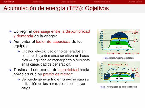
Acumulación de energía (TES): Objetivos
Corregir el desfasaje entre la disponibilidady demanda de la energía.Aumentar el factor de capacidad de losequipos
El calor, electricidad o frío generados enhoras de baja demanda se utiliza en horaspico⇒ equipos de menor porte o aumentoen la capacidad de generación.
Trasladar la demanda de electricidad haciahoras en que su precio es menor:
Se puede generar frío en la noche para suutilización en las horas del día de mayorcarga.
Figura : Consumo sin acumulación
Figura : Acumulación de hielo en la noche

Introducción Clasificación Casos aplicación Transferencia calor Criterios diseño
Acumulación de energía (TES): Objetivos
Flexibilidad en los equipos de cogeneraciónMuchas veces los equipos de cogeneración operan para cubrir lasnecesidades de calor. Con sistemas de TES, esta restricción selibera y se puede realizar el “despacho“ de formas diferentes.
Aumento en la eficiencia de operación de los equipos vinculadosy del sistema energético en general
Equipos funcionando en un punto más cercano al óptimo (p.ej.generación de frío en la noche en que la temperatura exterior esmenor).Reducción de picos, utilización de electricidad en períodos valle,reducción de consumo total.
Aumentar la “confiabilidad” del sistema:Cualquier forma de acumulación de energía, normalmente hace aun sistema más robusto.

Introducción Clasificación Casos aplicación Transferencia calor Criterios diseño
Acumulación por calor latente
Materiales de cambio de fase (Phase Change Materials)
Materiales que sufren un cambio de fase en un rango detemperaturas de interés
¿Por qué son interesantes?
Absorción o liberación de gran cantidad de energía (latente) atemperatura fija o en un rango corto de temperaturas.Se puede utilizar para acumular energía utilizando menoscantidad de material y/o menor volumen que mediante calorsensible.
Estado de desarrolloEn algunas aplicaciones está asentada su inserción comercial(p.ej.: bancos de hielo para refrigeración)En la mayoría de aplicaciones está en fase de desarrollo conaún baja inserción
Introducción Clasificación Casos aplicación Transferencia calor Criterios diseño
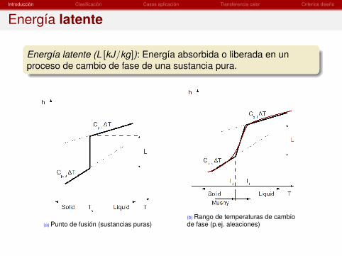
Energía latente
Energía latente (L [kJ/kg]): Energía absorbida o liberada en unproceso de cambio de fase de una sustancia pura.
(a) Punto de fusión (sustancias puras)(b) Rango de temperaturas de cambiode fase (p.ej. aleaciones)

Introducción Clasificación Casos aplicación Transferencia calor Criterios diseño
Acumulación por calor latente: Característicasdeseables
TermofísicasTemperatura de cambio de fase dentro de rango de operación:Asegura que el cambio de fase se efectúeAlto calor latente: Alta densidad energética (por unidad de masa,kJ/kg)Calor específico alto (ambas fases): Alta capacidad deacumulación de calor sensibleAlta densidad: Alta densidad energética por unidad de volumenkJ/m3
Alta conductividad térmica: Alta velocidad de transferencia decalor, para una extracción y acumulación rápida de calor
Introducción Clasificación Casos aplicación Transferencia calor Criterios diseño
Acumulación por calor latente: Característicasdeseables
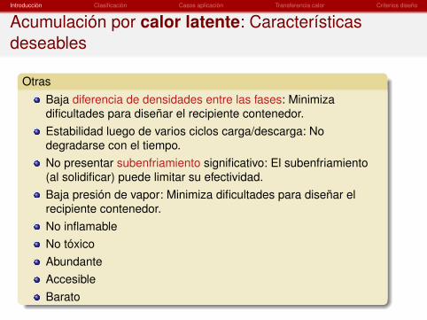
OtrasBaja diferencia de densidades entre las fases: Minimizadificultades para diseñar el recipiente contenedor.Estabilidad luego de varios ciclos carga/descarga: Nodegradarse con el tiempo.No presentar subenfriamiento significativo: El subenfriamiento(al solidificar) puede limitar su efectividad.Baja presión de vapor: Minimiza dificultades para diseñar elrecipiente contenedor.No inflamableNo tóxicoAbundanteAccesibleBarato

Introducción Clasificación Casos aplicación Transferencia calor Criterios diseño
Acumulación por calor latente
A destacarEn general, no existe un material que cumpla con todas lascaracterísticas deseadasNormalmente se utiliza el cambio de fase sólido-líquido, a pesarde presentar calores latentes menores que el líquido-vapordebido a la menor diferencia de densidades entre las fases.Alrededor de 0ºC el agua es un gran PCM aunque puedepresentar problemas de subenfriamiento, para lo cual seagregan aditivos que la inhiben (agentes nucleantes).
Tfusión ρ Cp k hslMaterial (ºC) (kg/m3) (KJ/kgK ) (W/mK ) (kJ/kg)
Agua/Hielo 0 990 4,19 0,9 / 2,18 344Parafinas -20/80 700/900 0,2 100/300
Sales hidratadas 10/140 1500/2000 0,6 100/300Mezclas de sales 200/1700 ∼ 2000 ∼ 1,5 ∼ 0,5/0,6 100/500 - 1000
Metales 20/1000 1000/10000 0,4/2 > 10 20/1000

Introducción Clasificación Casos aplicación Transferencia calor Criterios diseño
Determinación de propiedades físicas de PCMs
Differential Scanning Calorimeter (DSC)Calentamiento o enfriamiento de potencia variable.Se mantiene fijo la tasa de aumento/disminución detemperatura (K/min)
Sirve para determinar: punto/rango de fusión, calorlatente, calores específicos, grado desubenfriamiento (por las condiciones de este ensayopuede estar sobreestimado)
Cantidades muy pequeñas de material (1 - 10 mg).
Differential Thermal Analysis (DTA)Registro de variación de la temperatura con eltiempo
Sirve para determinar: punto/rango de fusión, gradode subenfriamiento, descomposición
Mayores cantidades de material (10g - 10 kg)
Figura : DSC
Figura : DTA

Introducción Clasificación Casos aplicación Transferencia calor Criterios diseño
Outline
1 Introducción
2 Clasificación de PCMs
3 Casos de aplicación
4 Mejoramiento de la velocidad de transferencia de calor
5 Criterios de diseño

Introducción Clasificación Casos aplicación Transferencia calor Criterios diseño
Clasificación
Figura : PCM classification. Extraído de Zalba et. al. 2003.

Introducción Clasificación Casos aplicación Transferencia calor Criterios diseño
Clasificación
Figura : Extraído de Cabeza et. al. 2011.

Introducción Clasificación Casos aplicación Transferencia calor Criterios diseño
Baja T: Comparativa
Figura : Extraído de Cabeza et. al. 2011.
Introducción Clasificación Casos aplicación Transferencia calor Criterios diseño
Baja T: Sales hidratadas
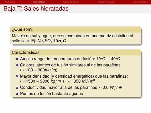
¿Qué son?
Mezcla de sal y agua, que se combinan en una matriz cristalina alsolidificar. Ej: Na2SO4,10H2O.
CaracterísticasAmplio rango de temperaturas de fusión: 10ºC –140ºCCalores latentes de fusión similares al de las parafinas(∼ 100− 300kJ/kg)Mayor densidad (y densidad energética) que las parafinas:(∼ 1500− 2000 kg/m3)⇒∼ 350 MJ/m3
Conductividad mayor a la de las parafinas ∼ 0,6 W/mKPuntos de fusión bastante agudos
Introducción Clasificación Casos aplicación Transferencia calor Criterios diseño
Baja T: Sales hidratadas
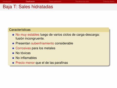
CaracterísticasNo muy estables luego de varios ciclos de carga-descarga:fusión incongruente.Presentan subenfriamiento considerableCorrosivas para los metalesNo tóxicasNo inflamablesPrecio menor que el de las parafinas

Introducción Clasificación Casos aplicación Transferencia calor Criterios diseño
Baja T: Sales hidratadas. Problemas
Fusión incongruente
M.mH2O → M + mH2OM.mH2O → M.pH2O + (m − p)H2OLa sal hidratada con menor contenido de agua M.pH2O (o la salanhidra M), de mayor densidad, cae al fondo del contenedor porefecto de la gravedad.Este proceso es irreversible, es decir, al solidifcar luego, elhidrato de menor contenido de agua no “encuentra”el aguanecesaria para reconstruir el hidrato original.Estrategias de mitigación:
Uso de agentes gelificantes para formar un gel en la fase líquida:Red sólida tridimensional (típicamente un polímero) que contienela sal hidratada en fase líquida y evita que caigaUso de agentes espesantes: Se agrega un material que aumentela viscosidad del líquido (Ej: SAP: super-absorbent polymer, CMC:carboximetilcelulosa, compuesto orgánico derivado de la celulosa)

Introducción Clasificación Casos aplicación Transferencia calor Criterios diseño
Baja T: Sales hidratadas. Problemas
SubenfriamientoO bien el líquido necesita una menor temperatura que la desolidificación termodinámica para la formación de núcleossólidos estables, o bien la velocidad de crecimimento de losnúcleos no es lo suficientemente alta.Una vez comienza la solidificación, la temperatura de la interfasesólido-líquido se incrementa hasta el punto de fusión.Si es excesiva, puede prevenir la extracción de calor latente.Medidas de mitigación:
Agentes nucleantes (nuecleación heterogénea): sustancias quepromueven la formación de núcleos estables. Típicamente aditivoscon estructura cristalina similar al del PCM.Uso de ondas de ultrasonido para agitar el líquido.

Introducción Clasificación Casos aplicación Transferencia calor Criterios diseño
Baja T: Sales hidratadas. Subenfriamiento
Figura : Subenfriamiento. Extraído de Cabeza et. al. 2011.

Introducción Clasificación Casos aplicación Transferencia calor Criterios diseño
Baja T: Sales hidratadas. Subenfriamiento.
Figura : Extraído de Cabeza et. al. 2011.
Introducción Clasificación Casos aplicación Transferencia calor Criterios diseño
Parafinas
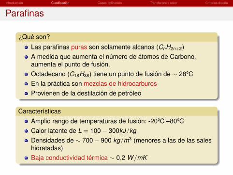
¿Qué son?
Las parafinas puras son solamente alcanos (CnH2n+2)A medida que aumenta el número de átomos de Carbono,aumenta el punto de fusión.Octadecano (C18H38) tiene un punto de fusión de ∼ 28ºCEn la práctica son mezclas de hidrocarburosProvienen de la destilación de petróleo
CaracterísticasAmplio rango de temperaturas de fusión: -20ºC –80ºCCalor latente de L = 100− 300kJ/kgDensidades de ∼ 700− 900 kg/m3 (menores a las de las saleshidratadas)Baja conductividad térmica ∼ 0,2 W/mK

Introducción Clasificación Casos aplicación Transferencia calor Criterios diseño
Parafinas
CaracterísticasPunto de fusión no definido (rango de temperaturas)Estable luego de muchos ciclos de carga-descargaNo presenta subenfriamientoNo corrosivasNo tóxicasNo fácilmente inflamablesPrecio mayor que las sales hidratadas

Introducción Clasificación Casos aplicación Transferencia calor Criterios diseño
Mezclas de sales
Salts, salt mixturesAdequate melting points for medium/high temp. applications.Not widely studied, but considerable current research (thermalstorage in thermosolar plants).Fusion temperatures ∼ 200− 1700ºC for pure salts, but withmixtures a wider range is obtained.Eutectic mixtures melt at a single temperature.Volume change depending on composition.Corrosive.Relatively cheap (much cheaper than metals).Overcooling.

Introducción Clasificación Casos aplicación Transferencia calor Criterios diseño
Mezclas de sales
Figura : Melting points and latent heats of several salts.
Figura : Some salt mixtures with melting points in the range of100 − 350ºC.
Figura : Properties of some nitrite salts.

Introducción Clasificación Casos aplicación Transferencia calor Criterios diseño
Outline
1 Introducción
2 Clasificación de PCMs
3 Casos de aplicación
4 Mejoramiento de la velocidad de transferencia de calor
5 Criterios de diseño

Introducción Clasificación Casos aplicación Transferencia calor Criterios diseño
Acondicionamiento térmico de edificaciones: equiposde acumulación
Para “aplanar”la curva de carga de los sistemas deacondicionamiento, usar calor residual, etc.
Hielo: producido durante la noche y utilizadodurante las horas pico de refrigeración del día.Tanque de agua aislado con un serpentíninterior por el que pasa un refrigerante.
Dos efectos contrapuestos respecto delconsumo energético: Alto rendimiento durantela noche debido a las menores temperaturasambiente. Pérdidas por las paredes y consumode energía para bombeo y controles.Disponibles comercialmente
Sistemas con PCM encapsulado: p.ejintercambiadores compactos, o lechos porososcon cápsulas de PCM. El encapsulamiento esnecesario para evitar la fuga de líquido.
Figura : Ice making equipment
Figura : PCM panel (up) andcompact storage module (down)

Introducción Clasificación Casos aplicación Transferencia calor Criterios diseño
Acondicionamiento térmico de edificaciones:integración en componentes de la edificación
Aumentar la inercia térmica de la edificación, “aplanando”lacurva de carga.
PCM in walls: incorporated into the structural material (concrete)or covering the inner face of the walls with a PCM wallboard(gypsum). Trombe walls can also incorporate PCM in order toreduce their width.PCM shutter: some window shutter containing PCMs have beenproposed. These are placed outside a window where they storeheat coming from solar radiation during the day. During the nightthis heat is directed into the room.PCM in floors and ceilings: as with walls, PCM can beincorporated with structural material of floors and ceilings or putin form of boards. An active heating or cooling can be achievedwith a more uniform load along the day or, in the cases whereelectricity is used, the peak load time can be displaced.
Necessary to ensure that the PCM undergoes periodic cycles ofcharge/discharge in order to effectively act as a latent energy storagematerial.

Introducción Clasificación Casos aplicación Transferencia calor Criterios diseño
Otros usos de baja T
Solar Thermal Storage in Tanks
Encapsulated PCM (paraffins or hydrated salts) can be put inside thestorage tank, where they would exchange heat with the water passingthrough it.
Conservation of Sensitive MaterialsFood transportTemperature sensitive medicationsElectronic components: restricting maximum temperatureStarting of engines and hydraulic machines at highertemperatures: heat is stored in a PCM while the engine isrunning. This heat is then used to preheat it in a new start.

Introducción Clasificación Casos aplicación Transferencia calor Criterios diseño
Acumulación para instalaciones de concentraciónsolar
Nowadays, thermal storage in thermosolar generation plants is atrending topic and PCM could play a role in this area.
Figura : Scheme of sandwich-like storagesystem (DISTOR project).
Figura : Heat exchanger beforeintegration into a container(DISTOR project).
Figura : T vs Enthalpy in combinedPCM/sensible storage for DSGplant.
Figura : Rankine cycle generation plant feeded bysteam generated in a Direct Steam Generation solarplant (DISTOR project).

Introducción Clasificación Casos aplicación Transferencia calor Criterios diseño
Outline
1 Introducción
2 Clasificación de PCMs
3 Casos de aplicación
4 Mejoramiento de la velocidad de transferencia de calor
5 Criterios de diseño
Introducción Clasificación Casos aplicación Transferencia calor Criterios diseño
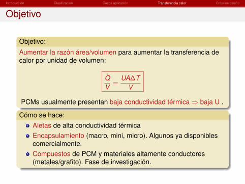
Objetivo
Objetivo:
Aumentar la razón área/volumen para aumentar la transferencia decalor por unidad de volumen:
Q̇V
=UA∆T
V
PCMs usualmente presentan baja conductividad térmica⇒ baja U .
Cómo se hace:Aletas de alta conductividad térmicaEncapsulamiento (macro, mini, micro). Algunos ya disponiblescomercialmente.Compuestos de PCM y materiales altamente conductores(metales/grafito). Fase de investigación.
Introducción Clasificación Casos aplicación Transferencia calor Criterios diseño
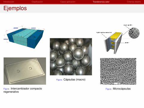
Ejemplos
Figura : Intercambiador compactoregenerativo
Figura : Cápsulas (macro)
Figura : Microcápsulas

Introducción Clasificación Casos aplicación Transferencia calor Criterios diseño
Outline
1 Introducción
2 Clasificación de PCMs
3 Casos de aplicación
4 Mejoramiento de la velocidad de transferencia de calor
5 Criterios de diseño
Introducción Clasificación Casos aplicación Transferencia calor Criterios diseño
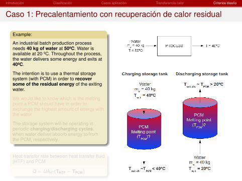
Caso 1: Precalentamiento con recuperación de calor residual
Example:
An industrial batch production processneeds 40 kg of water at 50ºC. Water isavailable at 20 ºC. Throughout the process,the water delivers some energy and exits at40ºC.
The intention is to use a thermal storagesystem (with PCM) in order to recoversome of the residual energy of the exitingwater.
We would like to know which is the meltingpoint a PCM should have in order toexchange the highest amount of energy withthe water.
The storage system will be operating inperiodic charging/discharging cycles,when water deliver/absorb energy to/fromthe PCM, respectively.
Heat transfer rate between heat transfer fluid(HTF) and PCM
Q̇ = UAHT(THTF − TPCM)

Introducción Clasificación Casos aplicación Transferencia calor Criterios diseño
Caso 1: Precalentamiento con recuperación de calor residual
Example:
An industrial batch production processneeds 40 kg of water at 50ºC. Water isavailable at 20 ºC. Throughout the process,the water delivers some energy and exits at40ºC.
The intention is to use a thermal storagesystem (with PCM) in order to recoversome of the residual energy of the exitingwater.
We would like to know which is the meltingpoint a PCM should have in order toexchange the highest amount of energy withthe water.
The storage system will be operating inperiodic charging/discharging cycles,when water deliver/absorb energy to/fromthe PCM, respectively.
Heat transfer rate between heat transfer fluid(HTF) and PCM
Q̇ = UAHT(THTF − TPCM)
Introducción Clasificación Casos aplicación Transferencia calor Criterios diseño
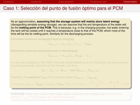
Caso 1: Selección del punto de fusión óptimo para el PCM
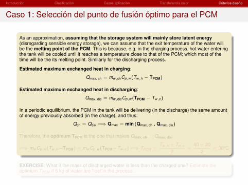
As an approximation, assuming that the storage system will mainly store latent energy(disregarding sensible energy storage), we can assume that the exit temperature of the water willbe the melting point of the PCM. This is because, e.g. in the charging process, hot water enteringthe tank will be cooled until it reaches a temperature close to that of the PCM; which most of thetime will be the its melting point. Similarly for the discharging process.
Estimated maximum exchanged heat in charging:
Qmax, ch = mw,chCp,w (Tw,h − TPCM)
Estimated maximum exchanged heat in discharging:
Qmax, dis = mw,disCp,w (TPCM − Tw,c)
In a periodic equilibrium, the PCM in the tank will be delivering (in the discharge) the same amountof energy previously absorbed (in the charge), and thus:
Qch = Qdis =⇒ Qmax = min (Qmax, ch , Qmax, dis)
Therefore, the optimum TPCM is the one that makes Qmax, ch = Qmax, dis.
=⇒ mw Cp,w (Tw,h−TPCM) = mw Cp,w (TPCM−Tw,c) =⇒ TPCM =Tw,h + Tw,c
2=
40 + 202
= 30ºC
EXERCISE: What if the mass of discharged water is less than the charged one? Estimate theoptimum TPCM if 5 kg of water are “lost”in the process.

Introducción Clasificación Casos aplicación Transferencia calor Criterios diseño
Caso 1: Selección del punto de fusión óptimo para el PCM
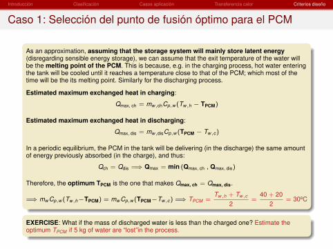
As an approximation, assuming that the storage system will mainly store latent energy(disregarding sensible energy storage), we can assume that the exit temperature of the water willbe the melting point of the PCM. This is because, e.g. in the charging process, hot water enteringthe tank will be cooled until it reaches a temperature close to that of the PCM; which most of thetime will be the its melting point. Similarly for the discharging process.
Estimated maximum exchanged heat in charging:
Qmax, ch = mw,chCp,w (Tw,h − TPCM)
Estimated maximum exchanged heat in discharging:
Qmax, dis = mw,disCp,w (TPCM − Tw,c)
In a periodic equilibrium, the PCM in the tank will be delivering (in the discharge) the same amountof energy previously absorbed (in the charge), and thus:
Qch = Qdis =⇒ Qmax = min (Qmax, ch , Qmax, dis)
Therefore, the optimum TPCM is the one that makes Qmax, ch = Qmax, dis.
=⇒ mw Cp,w (Tw,h−TPCM) = mw Cp,w (TPCM−Tw,c) =⇒ TPCM =Tw,h + Tw,c
2=
40 + 202
= 30ºC
EXERCISE: What if the mass of discharged water is less than the charged one? Estimate theoptimum TPCM if 5 kg of water are “lost”in the process.
Introducción Clasificación Casos aplicación Transferencia calor Criterios diseño
Caso 1: Selección del punto de fusión óptimo para el PCM
As an approximation, assuming that the storage system will mainly store latent energy(disregarding sensible energy storage), we can assume that the exit temperature of the water willbe the melting point of the PCM. This is because, e.g. in the charging process, hot water enteringthe tank will be cooled until it reaches a temperature close to that of the PCM; which most of thetime will be the its melting point. Similarly for the discharging process.
Estimated maximum exchanged heat in charging:
Qmax, ch = mw,chCp,w (Tw,h − TPCM)
Estimated maximum exchanged heat in discharging:
Qmax, dis = mw,disCp,w (TPCM − Tw,c)
In a periodic equilibrium, the PCM in the tank will be delivering (in the discharge) the same amountof energy previously absorbed (in the charge), and thus:
Qch = Qdis =⇒ Qmax = min (Qmax, ch , Qmax, dis)
Therefore, the optimum TPCM is the one that makes Qmax, ch = Qmax, dis.
=⇒ mw Cp,w (Tw,h−TPCM) = mw Cp,w (TPCM−Tw,c) =⇒ TPCM =Tw,h + Tw,c
2=
40 + 202
= 30ºC
EXERCISE: What if the mass of discharged water is less than the charged one? Estimate theoptimum TPCM if 5 kg of water are “lost”in the process.

Introducción Clasificación Casos aplicación Transferencia calor Criterios diseño
Caso 1: Estimación de la cantidad y volumen de PCM
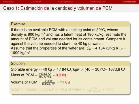
ExerciseIf there is an available PCM with a melting point of 30°C, whosedensity is 800 kg/m3 and has a latent heat of 180 kJ/kg, estimate theamount of PCM and volume needed for its containment. Compare itagainst the volume needed to store the 40 kg of water.Assume that the properties of the water are: Cp = 4.184 kJ/kg K; ρ =1000 kg/m3
Solution
Storable energy ∼ 40 kg × 4,184 kJ/kgK × (40− 30)°C= 1673,6 kJMass of PCM = 1673,6 kJ
180 kJ/kg = 9,3 kg
Volume of PCM = 9,3 kg800 kg/m3 = 11,6 lt
Volume needed to store the 40kg of water = 40 kg1000 kg/m3 = 40 lt

Introducción Clasificación Casos aplicación Transferencia calor Criterios diseño
Caso 1: Estimación de la cantidad y volumen de PCM
ExerciseIf there is an available PCM with a melting point of 30°C, whosedensity is 800 kg/m3 and has a latent heat of 180 kJ/kg, estimate theamount of PCM and volume needed for its containment. Compare itagainst the volume needed to store the 40 kg of water.Assume that the properties of the water are: Cp = 4.184 kJ/kg K; ρ =1000 kg/m3
Solution
Storable energy ∼ 40 kg × 4,184 kJ/kgK × (40− 30)°C= 1673,6 kJMass of PCM = 1673,6 kJ
180 kJ/kg = 9,3 kg
Volume of PCM = 9,3 kg800 kg/m3 = 11,6 lt
Volume needed to store the 40kg of water = 40 kg1000 kg/m3 = 40 lt

Introducción Clasificación Casos aplicación Transferencia calor Criterios diseño
Caso 1: Observaciones
If sensible energy capacities of liquid and solid phases areneglected, the maximum amount of energy that can bestored (charge) is that contained in the hot fluid, between itstemperature and the melting point of the PCM. The rest ofthe energy contained in the hot fluid cannot be absorbed aslatent heat in the PCM.In the case of the example, around half the energy is notabsorbed and is thrown.In the discharge, following the same reasoning, the maximumamount of energy that can be absorbed by the cold fluid comingin is that between its temperature (20°C) and the melting point ofthe PCM (30°C).

Introducción Clasificación Casos aplicación Transferencia calor Criterios diseño
Caso 1: Observaciones
In order to be able to store more energy (besides that stored inform of sensible energy in both phases), more than one PCMwith different melting points may be used (cascaded PCM) or acombination between sensible (e.g. solid) and latent heatstorage devices.Usually, sensible energy capacity is NOT negligible and shouldbe taken into account somehow.

Introducción Clasificación Casos aplicación Transferencia calor Criterios diseño
Caso 2: Diseño de sistema de acumulación con PCMpara centrales CSP
Standard: Molten-salt 2-tank (sensible)
Andasol I:
50MWe
Parabolic trough
7-8 hours storage
Studied alternative: single-tank using molten salt as HTF
Expected costs reduction:Total volume reductionLess molten salt

Introducción Clasificación Casos aplicación Transferencia calor Criterios diseño
Operating conditions of single-tank TES
ConditionsTin,charge = 390°CTin,discharge = 290°COperating time not fixedRestrictions on outflow temperaturedetermine stop of each process
- DISCHARGE: Toutflow ≥ 375°C- CHARGE: Toutflow ≤ 305°C
Several charge/discharge cycles⇒Periodic state (independent of theinitial state)
Introducción Clasificación Casos aplicación Transferencia calor Criterios diseño
Different configurations of single-tank TES
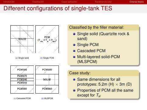
(a) Single solid (b) Single PCM
(c) Cascaded PCM (d) MLSPCM
Classified by the filler material:
Single solid (Quartzite rock &sand)Single PCMCascaded PCMMulti-layered solid-PCM(MLSPCM)
Case study:
Same dimensions for allprototypes: 5.2m (H) × 3m (D)Properties of PCM all the sameexcept for Tsl

Introducción Clasificación Casos aplicación Transferencia calor Criterios diseño
Single-solid tank: thermocline degradation
Filler: Quartzite rock & sand1ST CYCLE 2ND CYCLE PERIODIC STATE
Cha
rge
Dis
char
ge
Stored Energy = 1.45 MWh - Stored/Capacity: 63.4 %

Introducción Clasificación Casos aplicación Transferencia calor Criterios diseño
Single-PCM tank: Melting point outside admissibleranges
Filler: KOH 3601ST CYCLE 2ND CYCLE PERIODIC STATE
Cha
rge
Dis
char
ge
Stored Energy: 1.00 MWh - Stored/Capacity: 24.5 % - Changing phase: 2.4 %

Introducción Clasificación Casos aplicación Transferencia calor Criterios diseño
Single-PCM tank: Melting point inside admissibleranges
Cha
rge
Dis
char
ge
KOH380 (periodic state)
Stored Energy: 2.19 MWhStored/Capacity: 53.4 %Changing phase: 13.1 %
KOH300 (periodic state)
Stored Energy: 2.20 MWhStored/Capacity: 53.5 %Changing phase: 13.1 %
Introducción Clasificación Casos aplicación Transferencia calor Criterios diseño
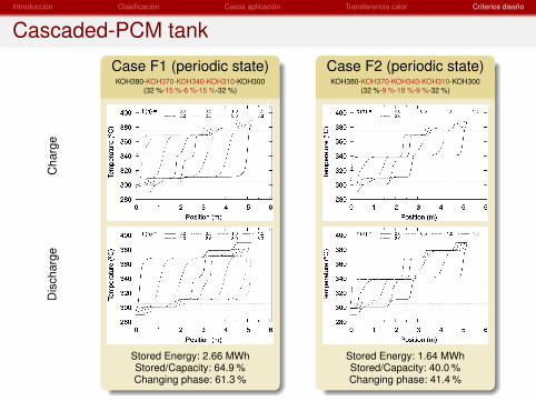
Cascaded-PCM tankC
harg
eD
isch
arge
Case F1 (periodic state)KOH380-KOH370-KOH340-KOH310-KOH300
(32 %-15 %-6 %-15 %-32 %)
Stored Energy: 2.66 MWhStored/Capacity: 64.9 %Changing phase: 61.3 %
Case F2 (periodic state)KOH380-KOH370-KOH340-KOH310-KOH300
(32 %-9 %-18 %-9 %-32 %)
Stored Energy: 1.64 MWhStored/Capacity: 40.0 %Changing phase: 41.4 %

Introducción Clasificación Casos aplicación Transferencia calor Criterios diseño
MLSPCM tank: 3 layersC
harg
eD
isch
arge
Case C2 (periodic state)KOH380-Qu-KOH300 (40 %-20 %-40 %)
Stored Energy: 2.42 MWhStored/Capacity: 64.5 %Changing phase: 38.4 %
Case C4 (periodic state)KOH380-Qu-KOH300 (10 %-80 %-10 %)
Stored Energy: 2.22 MWhStored/Capacity: 83.7 %Changing phase: 93.2 %

Introducción Clasificación Casos aplicación Transferencia calor Criterios diseño
Comparison
Single-solid Single-PCM MLSPCM cascaded PCMResults A B1 B2 B3 C1 C2 C4 D1 D2 F1 F2
Stored Energy (MWh) 1.45 1.00 2.19 2.20 2.32 2.42 2.22 1.48 2.43 2.66 1.64
Stored / Capacity ( %) 63.4 24.5 53.4 53.5 76.9 64.5 83.7 43.8 76.2 64.9 40.0
PCM changing phase ( %) - 2.4 13.1 13.1 73.6 38.4 93.2 47.9 81.7 61.3 41.4
Exergy difference at discharge(MWh)
0.69 0.48 1.04 1.05 1.11 1.15 1.06 0.70 1.16 1.27 0.78
Single-solid:- Degradation of thermocline due to temperature restrictions
Single-PCM:- If Tsl is not contained in an admissible range⇒ worst results- If Tsl is contained in an admissible range⇒ much better (not great) results
Cascaded-PCM:- PCM melting points at both ends inside admissible ranges- Performance highly dependent on the layer configuration- Case F1 with highest stored energy. Not the most efficient.
MLSPCM:- PCMs at both ends inside admissible ranges- Performance highly dependent on the layer configuration- Cases with best efficiencies in the use of capacity