ace engineering academy · ace engineering academy hyderabad|delhi|bhopal|pune|bhubaneswar|...
TRANSCRIPT
ACE Engineering Academy Hyderabad|Delhi|Bhopal|Pune|Bhubaneswar| Lucknow|Patna|Bengaluru|Chennai|Vijayawada|Vizag|Tirupati|Kukatpally |Kolkata

: 2 : Civil Engg. _ ESE MAINS
ACE Engineering Academy Hyderabad|Delhi|Bhopal|Pune|Bhubaneswar| Lucknow|Patna|Bengaluru|Chennai|Vijayawada|Vizag|Tirupati|Kukatpally |Kolkata
01. (a)
Sol:
112
x DxL
DDD
= 3.0x3
3.06.0
3.0x1.0
Convective acceleration as = Vxdx
dVx
2xx
3.0x1.04
Q
A
QV
23.0x1.0
405.0
23.0x1.0
06366.0
1.02
3.0x1.0
06366.0
x
V3
x
33.0x1.0
01273.0
Total acceleration at x = 2 is zero
Local acceleration + convective acceleration = 0
0x
VV
t
V xx
x
0
3.0x1.0
01273.0
A
Q
t
Q
A
13
xx
33.02.0
012732.005.0
t
Q
secsec//m100928.5t
Q 33
= 5.0928 lit
(b) (i)
Ans:
A geogrid is geosynthetic material used to
reinforce soils and similar materials. Geogrids
are commonly used to reinforce retaining
walls, as well as subbases or subsoils below
roads or structures. Soil pull apart under
tension. Compared to soil, geogrids are strong
in tension. This fact allows them to transfer
forces to a larger area of soil than would
otherwise be the case.
Geogrids are commonly made of polymer
materials, such as polyester, polyvinyl
alcohol, polyethylene or polypropylene. They
may be woven or knitted from yarns, heat-
welded from strips of material, or produced
by punching a regular pattern of holes in
sheets of material, then stretched into a grid.
These girds are formed by material ribs that
are intersected by their manufacture in two
directions: one in the machine direction (md),
which is conducted in the direction of the
manufacturing process. The other direction
600 mm
x
3 m
xx
300 mm

: 3 : Test – 14
ACE Engineering Academy Hyderabad|Delhi|Bhopal|Pune|Bhubaneswar| Lucknow|Patna|Bengaluru|Chennai|Vijayawada|Vizag|Tirupati|Kukatpally |Kolkata
will be perpendicular to the machine direction
ribs, which are called as the cross-machine
direction (CMD).
(ii)
Ans:
Liquefaction describes a phenomenon
whereby a saturated a partially.
Saturated soil substantially loses strength and
stiffness in response to an applied stress,
usually earthquake shaking or other sudden
change in stress condition, causing it to
behave like a liquid. Liquefaction
phenomenon generally occurs in the case of
saturated fine sands or silty sands.
Liquefaction Mitigation Techniques:
1. Soil Improvement Methods:
Dewatering
Relief well (to reduce porewater pressure)
Excavation of poor soils and replacement
with compacted fill grout injection
In situ densification (e.g vibroflotation,
Terraprobe, impact densification, dynamic
compaction, compaction piles, etc.)
Placement of additional fill (to increase
overburden pressures and soil strength)
2. Structural Fortification:
Strengthen structural connections
Add grade beams and tie beams
Extend pile support into deeper stable
soils.
(c)
Sol:
Population = 50,000
Discharge, Q = 50, 000 200
= 10 MLD = 0.1157 m3/sec
80% of water converted into sewage
Sewage factor = 0.8
Dry weather flow QDWF = 0.8 0.1157
= 0.0926 m3/sec
Assume maximum dry weather flow factor 3
Maximum dry weather flow
(QDWF)max = 3 QDWF
= 3 0.926 = 0.2778 m3/sec
Wet weather flow
360
AIRQWWF
(md) machine direction ribs
(cm
d) c
ross
mac
hine
dir
ectio
n ri
bs
Aperture
Junction
: 4 : Civil Engg. _ ESE MAINS
ACE Engineering Academy Hyderabad|Delhi|Bhopal|Pune|Bhubaneswar| Lucknow|Patna|Bengaluru|Chennai|Vijayawada|Vizag|Tirupati|Kukatpally |Kolkata
R = Rainfall intensity in mm/hr
Time of concentration tc = 40 + 10 = 50 min
as t > 20 min, a = 40, b = 20
Rainfall R =bt
a4.25
c
2050
404.25
= 14.51 mm/hr
360
51.145.050QWWF
= 1 m3/sec
Combined sewer discharge
Q = QDWF + QWWF
= 0.2778 + 1 = 1.2778 m3/sec
We know 2/13/2 SRn
1AQ
4
dR
1.2778 = 2/13/2
2 S4
d
015.0
1d
8
Sewere is running half A = 2d8
Assume manning’s constant n = 0.015
d8/3 = 3.889
d = 1.6641 m
Diameter of the sewer pipe is 1.6641 m
(d) (i)
Sol:
Advantages of the Tilting of Rails:
1) The tilting of rails maintains the gauge
properly
2) the wear of the head of the rail is
uniform due to tilting of rails
3) The tilting of rails increases the life of
sleepers as well as rails.
Disadvantages of the coning of wheels:
1) The smooth riding is produced by the
coning of wheels. But the pressure of
the horizontal component near the
inner edge of the rail has a tendency to
wear the rail quickly.
2) The horizontal component tends to turn
the rail outwardly and hence the gauge
is sometimes widened.
3) If no base-plates are provide, the
sleepers under the outer edge of the rail
are damaged.
(ii)
Sol:
Length of rail for B.G track = 12.80 m ≃ 13
Total length of track = 26 m
Total number of rail is13
26= 2 rails
Sleeper density = (n + 6)
= (13 + 6)
= 19 sleepers
Hence, total number of sleepers
= 2 19
= 38 sleepers
: 5 : Test – 14
ACE Engineering Academy Hyderabad|Delhi|Bhopal|Pune|Bhubaneswar| Lucknow|Patna|Bengaluru|Chennai|Vijayawada|Vizag|Tirupati|Kukatpally |Kolkata

: 6 : Civil Engg. _ ESE MAINS
ACE Engineering Academy Hyderabad|Delhi|Bhopal|Pune|Bhubaneswar| Lucknow|Patna|Bengaluru|Chennai|Vijayawada|Vizag|Tirupati|Kukatpally |Kolkata
(e)
Sol:
Given Horton’s equation
f = 5 + 10e–2t
Generally Horton’s equation
ft = fc + ktcc eff
o
Where fc = 5, cc ffo = 10
hr/mm15foc
at t = 0, ft = 15 mm/hr
at t = 1, ft = 5 + 10 e–2 = 6.3533 mm/hr
at t = 2, ft = 5 + 10 e–4 = 5.1831 mm/hr
at t = 3, ft = 5 + 10 e–6 = 5.02478 mm/hr
at t = 4, ft = 5 + 10 e–8 = 5.0033 mm/hr
at t = 5, ft = 5 mm/hr
From graph 6 = 5 + 10e–2 t
t = 1.1513 hr
Infiltration loss
4
1513.1
t2 dte105I
= 14.3 mm/hr
Surface runoff = Rainfall – infiltration (we
take in i > f values only)
= (1 – 0.1513) 6 + 10 + 7 – 14.3
= 7.7922 mm = 7.7922 10–3 m
Volume of runoff V = A 7.7922 10–3
= 36
36
m.M10
107922.7101000
= 7.7922 M.m3
02.
(a)
Apply Bernoulli’s equation between
(S) & (D)
D
2DD
s
2s Z
g2
VPZ
g2
VpS
SDDs ZZ
PP
78.081.9
101
1
0 1 2 3 4 51.1513
23456789101112131415
t (hrs)
i (mm/hr) 1.5 m
4 m
1.5 m
A B
S
D
C

: 7 : Test – 14
ACE Engineering Academy Hyderabad|Delhi|Bhopal|Pune|Bhubaneswar| Lucknow|Patna|Bengaluru|Chennai|Vijayawada|Vizag|Tirupati|Kukatpally |Kolkata
Ps = 6.65 kPa
Apply Bernoulli’s equation between
(C) & (D)
D
2DD
C
2CC Z
g2
VPZ
g2
VP
DC
2D ZZg2
V
5.581.92VD
VD = 10.38 m/s
Apply Bernoulli’s equation between
(A) & (C)
C
2CC
A
2AA Z
g2
VPZ
g2
VP
5.1086.120PA
PA = 14.37 9.81 0.8
kPa772.112PA
Apply Bernoulli’s equation between
(A) & (B)
B
2BB
A
2AA Z
g2
VPZ
g2
VP
g2
VPP 2BAB
5.5PP AB
PB = 69.608 kPa
Assuming vapour pressure 2.5 kPa,
atmospheric pressure 101 kPa
Ps = 2.5 kPa
Apply Bernoulli’s equation between
(S) & (D)
D
2DD
S
2SS Z
g2
VPZ
g2
VP
8.081.9
101Z
8.081.9
5.2S
ZS = 12.55 from D
Maximum height of summit
= 12.55 – 5.5
= 7.05 from water surface
(iv) maximum vertical depth of the pipe
= 12.55 m
(b)
Sol:
Rock
3 m
2 m
4 m
O
2 m
4 m
8 m
12 m
14 m
17 m
FictitiousFooting
Silt
Clay
Clay
Clay-I
Clay-II
Clay-III
12
m693
2L
3
2

: 8 : Civil Engg. _ ESE MAINS
ACE Engineering Academy Hyderabad|Delhi|Bhopal|Pune|Bhubaneswar| Lucknow|Patna|Bengaluru|Chennai|Vijayawada|Vizag|Tirupati|Kukatpally |Kolkata
Assume that the total load 2500 kN acts at a
depth of3
2L from the bottom of the pile cap
on a fictions footing as shown in the above
figure. The three clay layers (I, II & III)
shown above under go consolidation
settlement. The consolidation settlement is
determined by the following equation for each
clay layer.
o
o10
o
cf log
e1
CHS
o = effective in-situ a stress at centre of
each clay layer
= Increase in effective stress at centre of
each clay layer due to fictious footing
load.
Computation of o at centre of each clay
layer:
For clay layer-I
o = 2 + 2 + (4 + 2)
= 2 16 + 2 19.2 + 6 (19.2 – 9.81)
= 126.74 kPa
(w is taken as 9.81 kN/m3)
For clay layer II
o = 2 16 + 2 19.2 + 8 (19.2 – 9.81)
+ 1(18.24 – 9.81)
= 153.95 kPa
For clay layer –III
81.9205.181.924.18195.153o
= 177.67 kPa
Computation of at centre of each clay
layer:
ZLZB
Q
oo for 2V to 1H load
dispersion
Q = 2500 kN
Bo = width of pile block = (3S +d)
= (3 0.9 + 0.3)
= 3 m
Lo = length of pile block = (4S + d)
= 4 0.9 + 0.3 = 3.9 m
Z = depth to the centre of each clay layer,
from the fictious footing.
For layer- I; (Z = 2 m)
kPa75.8429.323
2500
For layer- II; (Z = 5 m)
s
sLo
Bo
: 9 : Test – 14
ACE Engineering Academy Hyderabad|Delhi|Bhopal|Pune|Bhubaneswar| Lucknow|Patna|Bengaluru|Chennai|Vijayawada|Vizag|Tirupati|Kukatpally |Kolkata
kPa11.3559.353
2500
For layer- III; (Z = 7.5 m)
88.205.79.35.73
2500
kPa
Computation of Settlements:
Layer-I :
o
o10
o
C1 log
e1
CHS
74.126
75.8474.126log
8.01
23.04 10
= 0.114 m
Layer-II:
95.153
11.3595.153log
08.11
34.02S 102
= 0.029 m
Layer-III:
67.177
88.2067.177log
7.01
2.03S 103
= 0.017 m
Total consolidation settlement,
S = S1 + S2 + S3
S = 0.114 + 0.029 + 0.017
= 0.16 m
= 16 cm
Total settlement, S = 16 cm
(c)
Sol:
The time required for the pedestrians to
cross the road = walk time +pV
W
sec67.262.1
2010
The green time Given for concurrent
vehicles to cross the road
= Given interval + intergreen time
= 14 + 6 = 20 s
Which is less than pedestrian crossing time
of 26.67. Therefore, pedestrian crossing time
is insufficient.
v = 50 18
5 = 13.89 m/s
gf2
vvtSSD
2
5.081.92
89.13189.13
2
= 33.56 m
Time required to cross the intersection
v
WSSD
89.13
20656.33 = s28.4
89.13
56.59
The intergreen time (IG) = Amber + all red
time
= 2 + 2 = 4 sec
IG < 4.28 sec
Dilemma occurs at the junction
To clear the dilemma the IG should be
increased to 4.28 sec
: 10 : Civil Engg. _ ESE MAINS
ACE Engineering Academy Hyderabad|Delhi|Bhopal|Pune|Bhubaneswar| Lucknow|Patna|Bengaluru|Chennai|Vijayawada|Vizag|Tirupati|Kukatpally |Kolkata

: 11 : Test – 14
ACE Engineering Academy Hyderabad|Delhi|Bhopal|Pune|Bhubaneswar| Lucknow|Patna|Bengaluru|Chennai|Vijayawada|Vizag|Tirupati|Kukatpally |Kolkata
03. (a)
Sol:
Risk = 1 - safety
= 1 - 0.8 = 0.2
Risk = 1 – qn
0.2 = 1 – q20
q20 = 0.8
(1 – p)20 = 0.8
p = 0.0110
90p
1T years
For return period of T = 90 years
p1nny t
= – 011.01nn
yt = 4.5043
Frequency factor KT =2825.1
5778.0y t
2825.1
5778.05043.4
= 3.0616
Magnitude of flood at 90 years
XT = TKX
= 1200 + 3.0616 650
= 3190 m3/sec
To increase the life of the structure 40 years
Risk = 1 – (1 – p)n
0.2 = 1 – (1 – p)40
(1 – p)40 = 0.8
p = 5.5630 10–3
Return period T = 180p
1 years
For return period T = 180 years
yt = p1nn
yt = 5.188
Frequency factor2825.1
5778.0yK t
T
2825.1
5778.0188.5
= 3.6
Magnitude of flood at 180 years
Tkxx TT
= 1200 + 3.6 650
= 3537 m3/sec
(b)
Sol:
Assuming the each pipe as following flow
Consider a loop ABCDA
40B
70
C 20
k = 2
80
30
A60
k = 2
D
30
50
k = 1
k = 1

: 12 : Civil Engg. _ ESE MAINS
ACE Engineering Academy Hyderabad|Delhi|Bhopal|Pune|Bhubaneswar| Lucknow|Patna|Bengaluru|Chennai|Vijayawada|Vizag|Tirupati|Kukatpally |Kolkata
Hardly cross procedure for 1st correction.
Pipe Assumed flow Qak(given)
HL = k 2aQ
a
L
Q
H Corrected Q after first correctionQ = Qa + 1
AB 30 2 1800 60 9.23
BC 70 1 4900 70 49.23
CD 50 2 5000 100 29.23
DA –30 1 –900 30 –50.77
HL = 10,800a
L
Q
H260
Where, 77.202602
800,10
Q
Hx
H
a
L
L1
Hardy cross procedure for 2nd correction
Pipe Assumed flow Qak(given)
HL = k 2aQ
a
L
Q
H Corrected Q after first correctionQ = Qa + 1
AB 9.23 2 170.38 18.46 4.3544
BC 49.23 1 2423.6 49.23 44.3544
CD 29.23 2 1708.78 58.46 24.3544
DA –50.7 1 –2577.6 50.77 –55.6455
HL = +1725.16a
L
Q
H= 176.92
92.1762
16.1725
Q
Hx
H
a
L
L2
= – 4.8755
The final flow rate in each pipe
40
44.3544
24.3544
80
55.6455
A60
4.3544B
C
D
20

: 13 : Test – 14
ACE Engineering Academy Hyderabad|Delhi|Bhopal|Pune|Bhubaneswar| Lucknow|Patna|Bengaluru|Chennai|Vijayawada|Vizag|Tirupati|Kukatpally |Kolkata

: 14 : Civil Engg. _ ESE MAINS
ACE Engineering Academy Hyderabad|Delhi|Bhopal|Pune|Bhubaneswar| Lucknow|Patna|Bengaluru|Chennai|Vijayawada|Vizag|Tirupati|Kukatpally |Kolkata
(c)
Sol:
(i) To find seepage loss rate, Q:
Nf = 6, Nd = 12, H = 12 m
K = 1.333 10–6 m/sec
= 1.333 10–6 60 60 24
= 0.1152 m/day
Seepage loss, Q =d
f
N
NKH
12
6121152.0
= 0.691 m3/day.m
(ii) To find factor of safety against heave on the
D/S of sheet pile:
F.O.S safety against heave,uw h
zF
Z = depth of sheet pile below bed level
hu = uplift pressure head at bottom of sheet
pile
Z = 6 m, hu = 3.5 m
= sat – w = 19.5 – 9.81 = 9.69 kN/m3
w = 9.81 kN/m3
uw h
zF
5.381.9
669.9
= 1.69
12 m
6 m15 m
z
w hu

: 15 : Test – 14
ACE Engineering Academy Hyderabad|Delhi|Bhopal|Pune|Bhubaneswar| Lucknow|Patna|Bengaluru|Chennai|Vijayawada|Vizag|Tirupati|Kukatpally |Kolkata
(d)
Sol:
Assume
Kv = 0.98, speed ratio, Ku = 0.46
gH2KV v
30081.9298.0
= 75.19 m/sec
gH2Ku u
30081.9246.0
= 35.29 m/sec
QH
Po
300Q9810
10600085.0
3
Q = 2.399 m3/sec
60
DNu
60
550D = 35.29 m/sec
D = 1.225 m
10
1
D
d
10
225.1d
= 0.1225 m = 122.5 mm
Area of jet
2)1225.0(4
a = 0.0118 m2
Total jet area requiredV
Q
19.75
399.2
= 0.0319 m2
No. of jets required0118.0
0319.0
= 2.7 ≃ 3
Thus three jets are required each having a
diameter
2dd
A
2d4
0319.0
d = 116.4 mm
Check:
5.10
1
225.1
1164.0
D
d
04. (a)
Sol:
Discharge Q = 9000 m3/day
hr/it24
109000 3
= 375000 lit / hr
Rate of filtration = 3000 lit/hr/m2
To find the size & Number of filter beds
Total area of filter =filtrationofRate
eargDisch

: 16 : Civil Engg. _ ESE MAINS
ACE Engineering Academy Hyderabad|Delhi|Bhopal|Pune|Bhubaneswar| Lucknow|Patna|Bengaluru|Chennai|Vijayawada|Vizag|Tirupati|Kukatpally |Kolkata
3000
375000
= 125 m2
Assume size of each filter = 10 5
Number of filters =50
125 = 2.5 ≃ 3
(ii) Design of under–drainage system.
Manifold– lateral under drainage system.
Let us assume that the area of the perforation
is 0.2% of the total filter area.
Total area of perforation = 0.2% Filter
area
50100
2.0 = 0.1 m2
Assuming the area of each lateral
= 2 times the area of perforation
= 2 0.1
= 0.2 m2
Assuming the area of the manifold to be about
twice the area of laterals.
Area of Manifold = 2 0.2 = 0.4 m2
Diameter of manifold (d)
4.0d4
2
d = 0.7136 m
d = 71.36 cm
length of each lateral =2
713.05
= 2.14 m
Assuming spacing between lateral
= 20 cm c/c
Number of lateral on each side
lateraleachofspacing
length =
2.0
10 = 50
Total Number of lateral = 2 50 = 100
lateralofNumber
lateralofareaTotallateraleachofArea
100
2.0 = 0.2 10–2
2102.04
lateralofDiameter =0.05 m
= 5 cm
Assuming the diameter of perforation = 8 mm
231084
nperforatioeachofArea
= 5.026 10–5 m2
Number of perforation required
nperforatioeachofArea
nperforatioofareaTotal
510026.5
1.0
= 1989.65
Pipe
Laterals
0.713 m
0.2m
5 m
10 m
Central Manifold

: 17 : Test – 14
ACE Engineering Academy Hyderabad|Delhi|Bhopal|Pune|Bhubaneswar| Lucknow|Patna|Bengaluru|Chennai|Vijayawada|Vizag|Tirupati|Kukatpally |Kolkata
Perforation on each side
lateralofNumber
nperforatioofnumberTotal
100
65.1989 = 19.96 ≃ 20
Spacing of perforation
lateraleachpernperforatioofNumber
lateraleachoflength
20
14.2 = 107 10–3 m
= 10. 7 cm c/c
Check:
05.0
14.2
lateralofDiameter
lateraloflength = 42.8 ≯ 60
Hence ok.
Rate of backwash = 10, 000 lit/hr/m2
Volumes of back wash water
= ROB DOB area of each filter
= 5060
30000,10
= 250 m3
% water used for back washing
=filter
filter
ADOFROB
ADOBROB
100
30)6024(3000
3010000
100
= 7.09 %
(b)
Sol:
Spillway is a high weir, Cd = 2.2
To calculate approximate value of He,
Q =Cd Le2/3
eH Le = 8 12
= 96 m
10000 = 2.2 (96) 2/3eH
m08.13962.2
10000H
3/2
e
Given
Height of spillway above the river bed
h = 210 110 = 100 m
33.164.708.13
100
H
h
d
It is a high spillway, velocity head can be
neglected,
7.108.13
10008.13
H
hH
e
e
Therefore, there is no effect of tailwater
condition.
Up stream slop: Upstream face of dam and
spillways is kept vertical. In the lower part a
batter of 1:10 may be provided Cd remains
unchanged.
Effective length of spillway:
Le = L 2 [ NKP + Ka] He
With rounded nose having 90 cut,

: 18 : Civil Engg. _ ESE MAINS
ACE Engineering Academy Hyderabad|Delhi|Bhopal|Pune|Bhubaneswar| Lucknow|Patna|Bengaluru|Chennai|Vijayawada|Vizag|Tirupati|Kukatpally |Kolkata
Kp = 0.01 and Ka = 0.1, N = 7
Le = 96 –2 [ 7(0.01) + 0.1] 14.5
= 91.07 (He = assumed 14.5)
Q = CLe2/3
eH
10000 = 2.2 (91.07) 2/3eH
He = 14.44 m 14.5 m ok
(assumed)
Therefore crest profile will be designed for Hd
= 14.44 m.
Velocity of approach
44.141003796
10000Va = 0.75 m/s
m03.0g2
Vh
2a
a , negligible
Down stream profile:
For a vertical up stream face,
yH2x 85.0d
85.1
85.0
85.1
85.0d
85.1
44.142
x
H2
xy
349.19
xy
85.1
Tangent point is given by
0.25.0
1
dx
dy
2349.19
x85.1
dx
dy 85.0
x = 35.7728 m
y = 38.6736 m
x y
1 0.5
2 0.186
3 0.394
4
5
:
:
:
34 35.2
35.7728 38.673
According to US army corps, the upstream
curve of ogee spillway having vertical
upstream face should have the following
equation.
d85.0
d
85.1d H126.0
H
H27.0x724.0y
–0.4315 625.0d
35.0d H27.0xH
The upstream profile extends up to
x = –0.27 Hd = –0.27 14.44 = –3.89 m
Hd = 14.44 m
At
x =0, y = 8.0436 m
x = –0.50 y =6.2578 m
x = –1.0 y = 4.7213 m
x = –2.0 y = 2.436 m
x = –3.0 y = 1.315 m
x = –3.8988 m y = 1.8194 m
: 19 : Test – 14
ACE Engineering Academy Hyderabad|Delhi|Bhopal|Pune|Bhubaneswar| Lucknow|Patna|Bengaluru|Chennai|Vijayawada|Vizag|Tirupati|Kukatpally |Kolkata
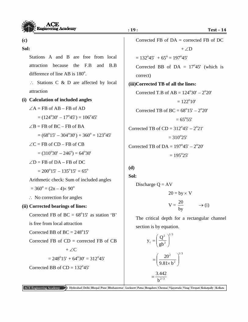
(c)
Sol:
Stations A and B are free from local
attraction because the F.B and B.B
difference of line AB is 180o.
Stations C & D are affected by local
attraction
(i) Calculation of included angles
A = FB of AB – FB of AD
= (124o30 – 17o45) = 106o45
B = FB of BC – FB of BA
= (68o15 – 304o30) + 360o = 123o45
C = FB of CD – FB of CB
= (310o30 – 246o) = 64o30
D = FB of DA – FB of DC
= 200o15 – 135o15 = 65o
Arithmetic check: Sum of included angles
= 360o = (2n – 4) 90o
No correction for angles
(ii) Corrected bearings of lines:
Corrected FB of BC = 68o15 as station ‘B’
is free from local attraction
Corrected BB of BC = 248o15
Corrected FB of CD = corrected FB of CB
+ C
= 248o15 + 64o30 = 312o45
Corrected BB of CD = 132o45
Corrected FB of DA = corrected FB of DC
+ D
= 132o45 + 65o = 197o45
Corrected BB of DA = 17o45 (which is
correct)
(iii)Corrected TB of all the lines:
Corrected T.B of AB = 124o30 – 2o20
= 122o10
Corrected TB of BC = 68o15 – 2o20
= 65o55
Corrected TB of CD = 312o45 – 2o21
= 310o25
Corrected TB of DA = 197o45 – 2o20
= 195o25
(d)
Sol:
Discharge Q = AV
20 = by V
V =by
20 (i)
The critical depth for a rectangular channel
section is by equation.
3/1
2
2
c gb
Qy
3/1
2
2
b81.9
20
3/2b
442.3
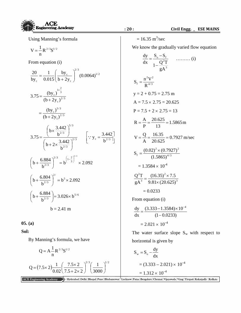
: 20 : Civil Engg. _ ESE MAINS
ACE Engineering Academy Hyderabad|Delhi|Bhopal|Pune|Bhubaneswar| Lucknow|Patna|Bengaluru|Chennai|Vijayawada|Vizag|Tirupati|Kukatpally |Kolkata
Using Manning’s formula
2/13/2 SRn
1V
From equation (i)
2/1
3/2
c
c
c
)0064.0(y2b
by
015.0
1
by
20
3/2c
3
21
c
)y2b(
)by(75.3
3/21
3/5c
)y2b(
)by(
3/2
3/2
3/5
3/2
b
442.32b
b
442.3b
75.3
3/2c b
442.3y
092.2bb
884.6b
3/5
3
21
3/2
3/2
092.2bb
804.6b 5
/2
3/2
6/53/2
b026.3b
884.6b
b = 2.41 m
05. (a)
Sol:
By Manning’s formula, we have
2/13/2 SRn
1AQ
2/13/2
3000
1
225.7
25.7
02.0
125.7Q
= 16.35 m3/sec
We know the gradually varied flow equation
3
2fo
gA
TQ1
SS
dx
dy
……… (i)
3/4
22
f R
VnS
y = 2 + 0.75 = 2.75 m
A = 7.5 2.75 = 20.625
P = 7.5 + 2 2.75 = 13
m5865.113
625.20
P
AR
7927.0625.20
35.16
A
QV m/sec
3/4
22
f )5865.1(
)7927.0()02.0(S
= 1.3584 10-4
3
2
3
2
)625.20(81.9
5.7)35.16(
gA
TQ
= 0.0233
From equation (i)
)0233.01(
10)3584.1333.3(
dx
dy 4
= 2.021 10–4
The water surface slope Sw with respect to
horizontal is given by
dx
dySS ow
= (3.333 – 2.021) 10–4
= 1.312 10–4
: 21 : Test – 14
ACE Engineering Academy Hyderabad|Delhi|Bhopal|Pune|Bhubaneswar| Lucknow|Patna|Bengaluru|Chennai|Vijayawada|Vizag|Tirupati|Kukatpally |Kolkata
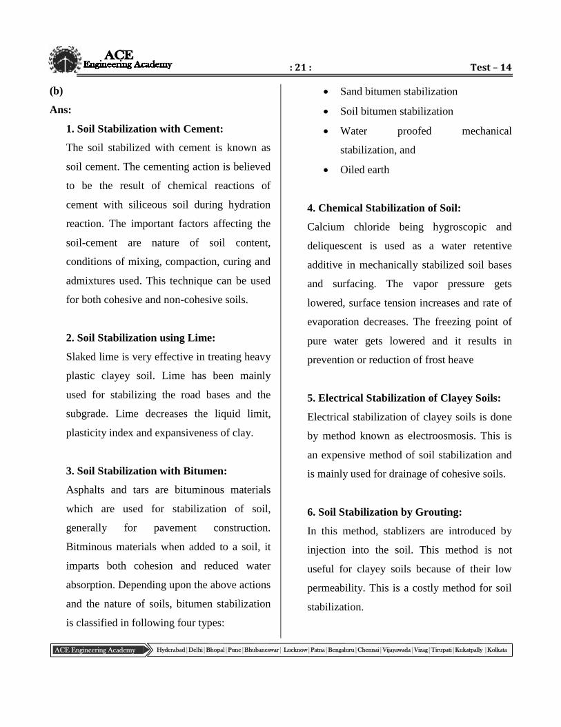
(b)
Ans:
1. Soil Stabilization with Cement:
The soil stabilized with cement is known as
soil cement. The cementing action is believed
to be the result of chemical reactions of
cement with siliceous soil during hydration
reaction. The important factors affecting the
soil-cement are nature of soil content,
conditions of mixing, compaction, curing and
admixtures used. This technique can be used
for both cohesive and non-cohesive soils.
2. Soil Stabilization using Lime:
Slaked lime is very effective in treating heavy
plastic clayey soil. Lime has been mainly
used for stabilizing the road bases and the
subgrade. Lime decreases the liquid limit,
plasticity index and expansiveness of clay.
3. Soil Stabilization with Bitumen:
Asphalts and tars are bituminous materials
which are used for stabilization of soil,
generally for pavement construction.
Bitminous materials when added to a soil, it
imparts both cohesion and reduced water
absorption. Depending upon the above actions
and the nature of soils, bitumen stabilization
is classified in following four types:
Sand bitumen stabilization
Soil bitumen stabilization
Water proofed mechanical
stabilization, and
Oiled earth
4. Chemical Stabilization of Soil:
Calcium chloride being hygroscopic and
deliquescent is used as a water retentive
additive in mechanically stabilized soil bases
and surfacing. The vapor pressure gets
lowered, surface tension increases and rate of
evaporation decreases. The freezing point of
pure water gets lowered and it results in
prevention or reduction of frost heave
5. Electrical Stabilization of Clayey Soils:
Electrical stabilization of clayey soils is done
by method known as electroosmosis. This is
an expensive method of soil stabilization and
is mainly used for drainage of cohesive soils.
6. Soil Stabilization by Grouting:
In this method, stablizers are introduced by
injection into the soil. This method is not
useful for clayey soils because of their low
permeability. This is a costly method for soil
stabilization.
: 22 : Civil Engg. _ ESE MAINS
ACE Engineering Academy Hyderabad|Delhi|Bhopal|Pune|Bhubaneswar| Lucknow|Patna|Bengaluru|Chennai|Vijayawada|Vizag|Tirupati|Kukatpally |Kolkata
7. Soil Stabilization by Geotextiles and
Fabrics:
Geotextiles are porous fabric made of
synthetic materials such as polyethylene,
polyester, nylons and polyvinyl chloride.
Woven, non-woven and gird form varieties of
geotextiles are available. Geotextiles have a
high strength. When properly embedded in
soil, it contributes to its stability. It is used in
the construction of unpaved roads over soft
soils.
(c)
Sol:
Quantity of sewage produced per day
= 200 150 0.8
= 24,000 l/day
Quantity of sewage produced during detention
time of 24 hrs
2424
000,24 lit
= 24,000 lit
= 24 m3
Now sludge deposition in the tank @ 40
lit/person/year assume cleaning period 6
months
Sludge volume =12
620040
= 4000 lit = 4 m3
Total required capacity of the tank
= Capacity of sewage + capacity of sludge
= 24 + 4 = 28 m3
Assume 1.5 m depth, length : width = 2 : 1
Surface area 667.185.1
28 m2
L B = 18.667
2B2 = 18.667
B = 3.055 3 ,
L = 6 m
Hence, use 6 m 3 m (1.5 + 0.3) m sized
septic tank
Diameter of soak-pit:
Area required for the soak pit =2500
24000
= 9.6 m2
Area of soak-well required = 9.6 m2
6.9d4
2
d = 3.5 m
Diameter of soak pit = 3.5 m

: 23 : Test – 14
ACE Engineering Academy Hyderabad|Delhi|Bhopal|Pune|Bhubaneswar| Lucknow|Patna|Bengaluru|Chennai|Vijayawada|Vizag|Tirupati|Kukatpally |Kolkata
(d) (i)
Sol:
B.S I.S F.S Rise Fall R.L R.L
0.405 69.980 A Starting point
1.035 0.630 62.350 B
1.930 0.895 61.455 C
2.895 0.965 60.490 D
3.805 0.910 59.580 E
0.715 4.760 0.955 58.625 F. (Change point)
2.060 1.345 57.280 G
3.160 1.100 56.180 H
4.415 1.255 54.925 I End point
Back sight
= 1.120
Fore sight =
9.175
Rise
= 0
Fall
=8.055
BS – FS = 1.120 – 9.175 = - 8.055 m
Rise – Fall = 0 – 8.055 = – 8.055 m
Last R.L– First R.L = 54.925– 62.980 = – 8.055 m
Distance between the starting point A and the end point B
= 8 25 = 200 m
Fall from A to B = 8.055 m
Gradient of the straight line AB83.24
1
200
055.8
Falling gradient = 1 vertical to 24.83 horizontal

: 24 : Civil Engg. _ ESE MAINS
ACE Engineering Academy Hyderabad|Delhi|Bhopal|Pune|Bhubaneswar| Lucknow|Patna|Bengaluru|Chennai|Vijayawada|Vizag|Tirupati|Kukatpally |Kolkata
(ii)
Ans:
The fundamental axes of a theodolite are
1. Vertical axis
2. Trunnion axis
3. Line of collimation
4. Altitude level axis
5. Axis of plate level
A theodolite is said to be in proper condition
if the following conditions are satisfied:
1) The axis of the plate is perpendicular to the
vertical axis
2) The trunnion axis is perpendicular to the
vertical axis
3. The line of collimation is perpendicular to
the trunnion (horizontal) axis.
4. The axis of the altitude level is parallel to
the line of collimation.90o
Horizontal Axis
Line of Collimation
Altitude level Axis
Plate level Axis
Plate level Axis
90o90o
Vertical Axis
Fundamental Axes of a Theodolite

: 25 : Test – 14
ACE Engineering Academy Hyderabad|Delhi|Bhopal|Pune|Bhubaneswar| Lucknow|Patna|Bengaluru|Chennai|Vijayawada|Vizag|Tirupati|Kukatpally |Kolkata
(e) (i)
Ans:
Classification of River Training works:
1. High water training: This is also called
training for discharge. The river is trained to
provide sufficient and efficient cross-sectional
area for the expeditious passage of maximum
flood. It concerns mainly with alignment and
height of embankment for a given flood
discharge.
2. Low water training: In this case the river is
trained to provide sufficient depth for
navigation during low stage of river. This is
also called training for depth and is usually
achieved by contraction of the width of the
channel.
3. Mean water training: In this case the river is
trained to correct the configuration of river
bed for the efficient transport of sediment
load in order to keep the channel in good
shape. It can be called training for sediment.
Components of river training works:
Marginal embankment (dyke or levee):
The marginal embankment or dyke is an
earthen embankment of trapezoidal section
constructed approximately parallel to the bank
of the river to confine the flood water within a
section between the embankments.
Guide bank: Guide banks must be
constructed on both the approaches to protect
the structure from erosion. It is an earthen
embankment with curved heads on both the
ends.
As the guide bank was first designed by Bell,
it is sometimes known as Bell’s Bund. The
Guide bank serves the following purposes.
a) Protects the barrage from the effect of
scouring and erosion
Bridge Road
Bank protection
S
S
G
Dyke
Guide bank Guide bank
S = SpurG=Groyne
G
G

: 26 : Civil Engg. _ ESE MAINS
ACE Engineering Academy Hyderabad|Delhi|Bhopal|Pune|Bhubaneswar| Lucknow|Patna|Bengaluru|Chennai|Vijayawada|Vizag|Tirupati|Kukatpally |Kolkata
b) Provides a straight approach towards the
barrage
c) Controls the tendency of changing the
course of the river
Spurs: These are temporary structures
permeable in nature provided on the curve of
a river to protect the river bank from erosion.
These are projected from the river bank
towards the bed making angles 60 to 75 with
the bank of the river.
The function of the spurs is to break the
velocity of flow and to form a water pocket
on the upstream side where the sediments get
deposited.
Groynes: The function of groynes is similar
to that of spur. But these are impervious
permanent structures constructed on the curve
of a river to protect the river bank from
erosion. They extend from the bank towards
the bed by making an angle of 60 to 75 with
the bank.
Classification according to the function it
serves:
(a) Attracting groyne.
(b) Deflecting groyne.
(c) Repelling groyne.
(d) Sedimenting groyne.
Special types of groynes, such as:
(a) Denehy’s T-headed groyne.
(b) Hockey type groyne.
(c) Burma type groyne.
(ii)
Ans:
Canal fall or drop:
It is a structure constructed across a channel
to lower down the water level and dissipate
surplus energy. It is required when the natural
slope of the ground is greater than the
designed bed slope of the channel. The
difference in slopes is adjusted by
constructing a vertical drop.
Ogee falls, rapids and stepped falls, notch
falls, vertical falls and glacis type falls.
1. Ogee fall:
U/S BED
D/S BED
Ogee fall

: 27 : Test – 14
ACE Engineering Academy Hyderabad|Delhi|Bhopal|Pune|Bhubaneswar| Lucknow|Patna|Bengaluru|Chennai|Vijayawada|Vizag|Tirupati|Kukatpally |Kolkata
(i) There was considerable draw down
effect on the u/s resulting is bed
erosion.
(ii) Due to smooth transition, the kinetic
energy was preserved till sufficient
depth was scoured out below the fall
to ensure the formation of the
hydraulic jump.
2. Rapid fall:
Such a fall consists of a glacis sloping at 1
vertical to 10 to 20 horizontal. The long glacis
assured the formation of hydraulic jump. The
gentle slope admitted timber traffic. Hence,
the fall worked admirably. However, there
was very high cost of construction.
3. Notch fall:
The notches were designed to maintain the
normal water depth in the u/s channel at any
two discharge values. The depth discharge
relation was thus maintained with close
approximation. As the channel approached
the fall, there were neither drawdown nor
heading up of water.
4. Vertical Drop fall:
In the vertical drop fall, the nappe impinges
clear into the water cushion below.
5. Glacis type fall:
The glacis type of fall utilized the standing
wave phenomenon for dissipation of energy.
Generally glacis type fall is suitable as a
meter. The vertical drop fall is not suitable as
a meter due to the formation of partial
vacuum under the nappe.
Escapes: Structure constructed on an
irrigation channel for the disposal of surplus
water from the channel (It is called Surplus
Escape).
Sometimes, escapes are provided in the head
reaches of canal to scour out bed silt
deposited in the canal. They are called Canal
Scouring Escapes.
Some times, at the tail end of the channel
when it meets a drain, an escape is provided
to maintain the required FSL in the canal.
Such an escape is called Tail escape.
U/S
D/S1 in 15
Rapid Fall
U/S F.S.L Notch pier Notch Side wall
Sill of Notch Foundation wall
: 28 : Civil Engg. _ ESE MAINS
ACE Engineering Academy Hyderabad|Delhi|Bhopal|Pune|Bhubaneswar| Lucknow|Patna|Bengaluru|Chennai|Vijayawada|Vizag|Tirupati|Kukatpally |Kolkata
06. (a)
Sol:
(i) The discharge Q delivered by the pump is
given by
Q = kB1D11f
V
Given
B1 = 15 mm = 0.015 m
D1 = 400 mm = 0.400 m
1fV = 3 m/s
Assuming k = 1, we get
Q = 1 0.015 0.400 3
Q = 0.0565 m3/s
= 3390 litres/minute
(ii) Manimetric efficiency is given by
1w
mmano uV
gH
1
mano
m1w H
g
uV1
Hm = 30 m; mano = 75% = 0.75
75.0
30
g
uV 1w1 40 m ………. (i)
i.e., total head developed by the pump = 40 m
The pressure rise through the impeller
PP1 is 65% of the total head developed
by the pump. Thus
m26)4065.0(PP1
Applying Bernoulli’s equation between the
inlet and outlet tips of the impeller and
neglecting the head loss in the impeller,
g
uV
g2
Vp
g2
Vp 1w2
112
1
g2
V
g
uV
g2
Vpp 211w
21 1
V = Vf = 3 m/s
Thus by substitution, we get
g2
V40
81.92
)3(26
21
2
Or V1 = 16.84 m/s
But 2f
2w1 11
VVV
2f
21w 11
VVV
1f
V 3 m/s
Thus by substitution, we get
22w )3()84.16(V
1
= 16.57 m/s
By substituting in equation (i), we get
4081.9
u57.16 1
Or57.16
81.940u1
= 23.68 m/s
But60
NDu 1
1
: 29 : Test – 14
ACE Engineering Academy Hyderabad|Delhi|Bhopal|Pune|Bhubaneswar| Lucknow|Patna|Bengaluru|Chennai|Vijayawada|Vizag|Tirupati|Kukatpally |Kolkata
Or60
N400.068.23
Or400.0
6068.23N
= 1131 rpm
i.e., speed of the pump = 1131 rpm
(iii) From outlet velocity triangle, we have
1
1
w1
f
Vu
Vtan
Or 4219.057.1668.23
3tan
= 22 52
i.e., blade angle at outlet = 2252
(iv) From inlet velocity triangle
u
Vtan f
Or cotVu f
= 60
u = 3 cot 60 = 1.732 m/s
Also60
DNu
Or60
1131D732.1
Or1131
60732.1D
Or D = 0.029 m = 29 mm
i.e., the diameter of the impeller at inlet
= 29 mm
(b)
Sol:
Q yi= Population Per capita BOD
20 yi = 50000 80 10–3
/mg20020
108050000y
3
i
WR
WWRRmix QQ
yQyQy
315.05
y2315.0051 W
ye = 22.6 mg/l
100y
yy
i
ei
100200
6.22200
= 88.7%
ymix = 1 mg/l = Lo 5k1e1
Lo = 1.2872 mg/l
2315.05
095DO min
= 8.60 mg/l
Do = (DO)sat – (DO)min = 9 – 8.6 = 0.4 mg/l
Time taken to travel 60 km
60602412.0
1060 3
= 5.78 days ≃ 5.8 days
tko
tktk
22
o18.5
221 eDeekk
LkD
: 30 : Civil Engg. _ ESE MAINS
ACE Engineering Academy Hyderabad|Delhi|Bhopal|Pune|Bhubaneswar| Lucknow|Patna|Bengaluru|Chennai|Vijayawada|Vizag|Tirupati|Kukatpally |Kolkata
8.58.08.58.08.53.0 e4.0ee3.08.0
2870.13.0
= 0.131 mg/l
DO at 60 km (DO)sat – D5.8
= 9 – 0.131
= 8.868 mg/l
o1
12o
1
2
12c Lk
kkD1
k
kn
kk
1t
= 0.5023 days
Point at which it occurs
= velocity Time
= 0.5023 24 60 0.12
= 5.20 km
(c)
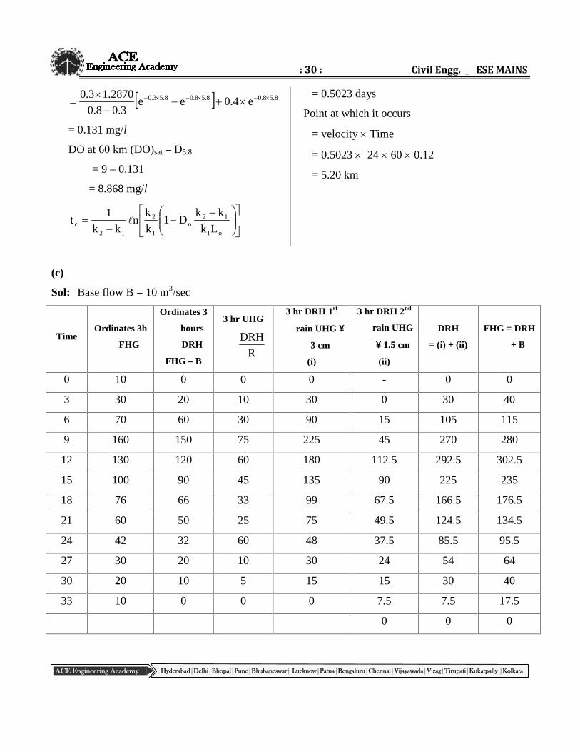
Sol: Base flow B = 10 m3/sec
TimeOrdinates 3h
FHG
Ordinates 3
hours
DRH
FHG – B
3 hr UHG
R
DRH
3 hr DRH 1st
rain UHG
3 cm
(i)
3 hr DRH 2nd
rain UHG
1.5 cm
(ii)
DRH
= (i) + (ii)
FHG = DRH
+ B
0 10 0 0 0 - 0 0
3 30 20 10 30 0 30 40
6 70 60 30 90 15 105 115
9 160 150 75 225 45 270 280
12 130 120 60 180 112.5 292.5 302.5
15 100 90 45 135 90 225 235
18 76 66 33 99 67.5 166.5 176.5
21 60 50 25 75 49.5 124.5 134.5
24 42 32 60 48 37.5 85.5 95.5
27 30 20 10 30 24 54 64
30 20 10 5 15 15 30 40
33 10 0 0 0 7.5 7.5 17.5
0 0 0

: 31 : Test – 14
ACE Engineering Academy Hyderabad|Delhi|Bhopal|Pune|Bhubaneswar| Lucknow|Patna|Bengaluru|Chennai|Vijayawada|Vizag|Tirupati|Kukatpally |Kolkata
Volume of the runoff using trapezoidal rule
= Area of Direct rainfall hydrograph
....yyy2yy2
h321no
10203250
66901201506020200
2
36003
= 6,674,400 m3
Runoff depth =areaCatchement
DRHofArea
= 10001072.333
400,674,66
mm
= 20 mm = 2 cm
07. (a)
Sol:
Given data:
Sandy soil, = 35o,
d = 17 kN/m3
Gs = 2.7, take w = 9.81 kN/m3
e1
G. swd
e1
7.281.917
e = 0.558
e1
eG swsat
558.01
558.07.281.9 = 20.51 kN/m3
At a depth of 4 m,
= 2.5 d + 1.5
= 2.5 d + 1.5 [sat – w]
= 2.5 17 + 1.5 [20.51 – 9.81]
= 58.55 kPa
(i) On the horizontal plane, the shear
strength of soil,
S = tan (C = 0 for sand)
= 58.55 tan 35o
= 41 kPa (Ans)
(ii) If W.T rises to G.L
At 4 m depth, = 4
= 4[20.51 – 9.81]
= 42.8 kPa
Shear strength S = tan
= 42.8 tan 35
= 29.97 kPa
Change in shear strength due to rise of WT
is = 41 - 29.97
= 11.03 kPa (decreases)
Shear strength decreases by 11.03 kPa
Ssat1.5
2.5 m4 m
d

: 32 : Civil Engg. _ ESE MAINS
ACE Engineering Academy Hyderabad|Delhi|Bhopal|Pune|Bhubaneswar| Lucknow|Patna|Bengaluru|Chennai|Vijayawada|Vizag|Tirupati|Kukatpally |Kolkata
(b)
Sol:
By Kerman momentum integral equation
xU 2
o
Where = Momentum thickness:
U
U1
U
U
o
dy
y
, dy = d and the limits of are
0 and 1
U
U= f() = 3
2
1
2
3
d
2
1
2
31
2
1
2
3f 3
1
0
3
1
0
6442
4
1
4
3
2
3
4
3
4
9
2
3d
1
0
754532
2854
3
854
3
34
9
22
3
1
0
75453
2854
3
854
3
34
9
4
3
28
1
20
3
8
1
20
3
12
9
4
3
= 0.1392
dx
dU1392.0 2
o
From the boundary conditions for a laminar
boundary layer
0
d
dfU
dy
dUT
0y
o
f() = 3
2
1
2
3
2
3
2
3
2
3
d
df
0n
2
0n
o =
U
2
3
Equating the two expressions for o,
0.1392
U
2
3
dx
dU 2
dxU
77.10d
Integrating on both sides
CxU
77.102
2
At x = 0, = 0 C = 0
xU
x55.21
22
xU
x65.4
xRe
x65.4
xU
Re x

: 33 : Test – 14
ACE Engineering Academy Hyderabad|Delhi|Bhopal|Pune|Bhubaneswar| Lucknow|Patna|Bengaluru|Chennai|Vijayawada|Vizag|Tirupati|Kukatpally |Kolkata
(c)
Sol:
Adopt Btigh’s creep theory
L = Total creep length
= 10+13+14+15+18 = 70 m
H = 7 m
10H
LC
at A:
lA = 10+13+14 = 37 M
m7.310
37h '
A
m3.37.37h A
7.3
3.3
A
hi A
(ii) Uplift pressure at B:
m5215141310B
m2.5C
h B'B
m8.12.57h B
Uplift pressure head at B
hB = 1.8 m
Uplift pressure at B
pB = WhB
= 18 kPa
(iii) Thickness of floor at C
lc = 10 + 13 = 23 m
Balanced head
m3.210
23
C
c1h '
c
Unbalanced head
3.27hHh 1cc = 4.7 m
Thickness of floor at c
1s
h
3
4t
c
cc
m5124.2
7.4
3
4
At C: Theoretical thickness of impervious
apron = 5 m
(d)
Sol:
Given: design speed V = 80 kmph,
gradients n1 = + 3.0% and n2 = – 5.0%
(a) Determination of safe stopping sight
distance, SSD
As there is ascending gradient on one side of
the summit and descending gradient on the
other side, the effect of gradients on the SSD
is assumed to get compensated and hence
ignored in the calculations.
13 m 15 m5 m 7 m
9 m
7 m
C A B

: 34 : Civil Engg. _ ESE MAINS
ACE Engineering Academy Hyderabad|Delhi|Bhopal|Pune|Bhubaneswar| Lucknow|Patna|Bengaluru|Chennai|Vijayawada|Vizag|Tirupati|Kukatpally |Kolkata
f254
VVt278.0SSD
2
Assuming t = 2.5 sec and f = 0.35 for V = 80
kmph
35.0254
805.280278.0SSD
2
= 55.6 + 72.0 = 127.6 ≃ 128 m
(b) Determination of length of summit curve:
Deviation angle N = 0.03 – (–0.05) = 0.08
Assuming L > SSD,
4.4
12808.0
4.4
NSL
22 = 297.9 m ≃ 298 m
This value of summit curve length L is
greater than SSD of 128 m as per the
assumption and therefore the calculated
length may be accepted for design
Length of summit curve, L = 298 m
08. (a)
Sol:
Given data:
C = 15 kPa, = 30o
n = 40%
Gs = 2.67
For = 30o , Nc = 37.2
Nq = 22.5
N = 19.7
e =n1
n
667.04.01
4.0
Assume w = 9.81 kN / m3
wsat
= (19.64 – 9.81)
= 9.83 kN/m3
For a general shear failure, Terzaghi’s
equation. To find gross allowable bearing
capacity, qs is given below.
DqF
1q nus
D
2
B2.01NB5.0
1NDCNL
B3.01
F
1q
qc
s
As W.T is at G.L, is used in the above
equation
L = Length of footing in metres
283.9
L
32.017.19383.95.0
15.22283.92.3715L
33.01
3
1q s
66.19L
6.0148.29070.422558
L
9.01
3
1q s
D = 2 m
B = 3 m

: 35 : Test – 14
ACE Engineering Academy Hyderabad|Delhi|Bhopal|Pune|Bhubaneswar| Lucknow|Patna|Bengaluru|Chennai|Vijayawada|Vizag|Tirupati|Kukatpally |Kolkata
66.19L
1.5883.969.140
L
4.167186
= 443.39 +L
3.109
The given external gross allowable bearing
pressure, q = 455 kPa
Equating, qs = q
455L
3.10939.443
L = 9.40 m
Length required, L = 9.40 m
(b)
Sol:
Correction of Elevation:
This basic length is to be increased at the
rate of 7% per 300 m elevation above mean
sea level.
Correction for elevation =300
100
100
7
= 14 m
Length of runway after correction for
elevation = (600 + 14) = 614 m
Correction for Temperature:
Standard atmospheric temperature at mean
sea-level = 15oC
Taking the temperature gradient as equal to
6.5oC per 1000 m rise in elevation, the
standard temperature at the airport site will
be:
Temperature at R.L 100
1000
1005.615
= 14.35oC
Difference between airport reference
temperature and standard atmospheric
temperature = (28 – 14.35) = 13.65oC
Applying correction at the rate of 1% for
every 1oC
Correction for temperature:
65.13614100
1
= 83.81 say 84 m
Corrected runway length = (614 + 84)
= 698 m
Correction for Gradient:
Effective gradient600
2.95L.R2.98L.R
600
3 or 0.5%
Applying correction for the effective
gradient at the rate of 20% for each 1%
effective gradient
Correction for gradient1
5.0698
100
20
= 69.8 ≃ 70 m
Actual length of runway = (698 + 70) = 768

: 36 : Civil Engg. _ ESE MAINS
ACE Engineering Academy Hyderabad|Delhi|Bhopal|Pune|Bhubaneswar| Lucknow|Patna|Bengaluru|Chennai|Vijayawada|Vizag|Tirupati|Kukatpally |Kolkata
Check:
Total correction for elevation and
temperature = (14 + 84) = 98 m
Percentage increase 100600
98 = 16.33%
According to ICAO this should not be more
than 35%
(c) (i)
Ans:
In Movable stadia hair method stadia
intercept is variable but staff intercept is
kept constant. A leveling staff on which line
of sight will bisect is called as base. If base
is kept horizontal it is a horizontal subtese
bar. In India, the subtense bars are usually
3.5 m long. It is mounted on a tripod. A
small spirit level is provided to level it. The
alidade provides a line of sight
perpendicular to the bar, which is thereby set
normal to the line of measurement. The
targets are set apart at a known distance and
the horizontal angle between them is read by
a theodolite. The horizontal distance can be
calculated as follows
D = S/β (206265) if β is in seconds
(ii)
Sol:
H
f
cetandisGround
cetandisMapScale
Where
H = height of camera above the selected
datum
Let the average ground be the selected
datum
50.8
0.25020Hor
mH
cm20
m0.250
cm50.8
= 588.2 m
Height of the tower above its base is given
by
m80
2.5885
r
dHh
= 36.7625 m
(iii)
Sol:
At upper culmination (transit)
Declination of the star = = (90 – α) – θ
Where
α = altitude; = latitude
= declination of star
= (90 – 28o) – 50o = 12o
Since latitude () > altitude (α) at upper
culmination, declination of star is towards
north (N)
= 12o N
β/2
β/2 S/2
S/2
D
: 37 : Test – 14
ACE Engineering Academy Hyderabad|Delhi|Bhopal|Pune|Bhubaneswar| Lucknow|Patna|Bengaluru|Chennai|Vijayawada|Vizag|Tirupati|Kukatpally |Kolkata
(d)
Sol:
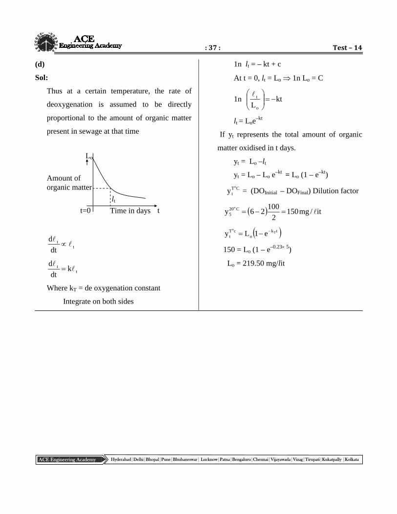
Thus at a certain temperature, the rate of
deoxygenation is assumed to be directly
proportional to the amount of organic matter
present in sewage at that time
tt
dt
d
tt k
dt
d
Where kT = de oxygenation constant
Integrate on both sides
1n lt = – kt + c
At t = 0, lt = Lo 1n Lo = C
1n ktLo
t
lt = Loe–kt
If yt represents the total amount of organic
matter oxidised in t days.
yt = Lo –lt
yt = Lo – Lo e–kt = Lo (1 – e–kt)
CTt
o
y = (DOInitial – DOFinal) Dilution factor
it/mg1502
10026y C20
5
o
tko
cTt
To
e1Ly
150 = Lo (1 – e–0.23 5)
Lo = 219.50 mg/lit
Lo
Amount oforganic matter
t=0 Time in days t
lt

: 38 : Civil Engg. _ ESE MAINS
ACE Engineering Academy Hyderabad|Delhi|Bhopal|Pune|Bhubaneswar| Lucknow|Patna|Bengaluru|Chennai|Vijayawada|Vizag|Tirupati|Kukatpally |Kolkata