1~ii!jilleel-ill!j i .. i·i:i~:i. - uminho
TRANSCRIPT
•
:I!). 1~II!Jilleel-ill!J e\':lhl:l'iull fttl-1~:ls' I .. iltel-'" I·I:I~:I.
R. M. Gensert and U. Kirsis, R. M. Gensert Associates, Cleveland, Ohio
Introduction
The East Liberty Plaz. will be a 20 story masonry wall bearing apartment building for the low income leveI. (Loca· tion: Pittsburgh, Pennsylvania; Architect: Tasso Katselas) It will be situated near the Pennley Park project that contains 15 masonry wall-bearing buildings ranging from faur to nine stories. These buildings proved to be more economical than steel ar concrete frarned buildings, using masonry walls as dividers between suites and corridors.
This 20 story building was designed in accordance with the City of Pittsburgh and State of Pennsylvania building codes. These codes embrace in part lhe American Standards Association code and some af the more liberal suggestions from the
publications of the Structural Clay Products Institute. AI· though Pittsburgh is located in Zone 1 for earthquake analysis, the intensity af seismic forces in Zone I does not control design ir lhe structure has inherent tensile resistance. However, it was the opinion of the Federal Housing Authority technical staff as well as the design engineers that a building of this height and type of construction should have some basis for lhe determination of duclility.
This chapter evaluates and gives the cri teria lhat were devcloped for Ihis building projecl wilh lhe cooperation of Mr. Oressel , Struclural Engineer wilh the Federal Housing Aulhor· ily in Washington, O. C.
Factors Considered in Planning the Building
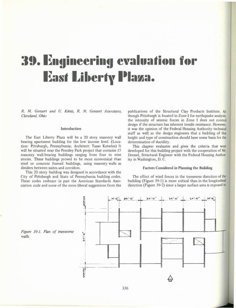
The effect of wind forces in the Iransverse direclion of lhe building (Figure 39·1) is more criticai Ihan in the longitudinal direction (Figure 39-2) since a larger surface area is exposed lo
-e"'t'·'·CFt-""'t-"~" t'l
Figure 39-1. Plan of transverse walls.
'.1 ·' 1
:;1
I I
- +1--r - -
~i -' -- - IX
336
Engineering Evaluation for East Liberty P/azo 337
,-
, I
C
I ,
L---
I1 I
. ~ 1~9'- O" . VARIES
r
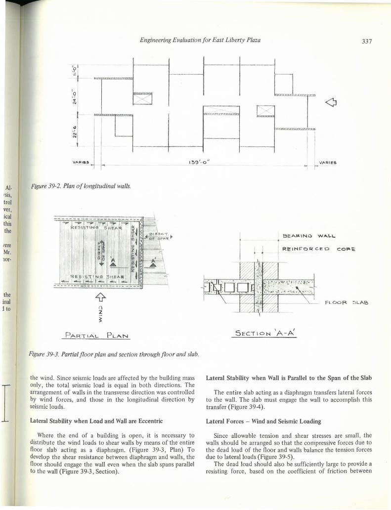
AI. Figure 39-2. Plan of longitudinal wal/s.
Isis, trol ver, ,ica! this the
lere Mr. 10[·
the inal j to
I
fl 2
~
Figure 39·3. Partial floor plan and section through floor and slab.
the wind. Sinee seismic load, are affeeted by the building mass only, the total seismie load is equal in both direetions. The arrangement Df walls in the transversc direction was control1ed by wind forces, and those in the longitudinal direetion by seismic loads.
lateral Stability when Load and WaU are Eceentrie
Where the end of a building is open, it is neeessary to distribute the wind loads to shear walls by means of the entire floor slab aeting as a diaphragm. (Figure 39-3, Plan) To devclop the shcar resistanee between diaphragm and walls, the floor should engage the wall cven whcn the slab spans parallel to the wall (Figure 39·3, Section).
• •
FLOOFt ~LAB
, I
SECTION A-A
Lateral Stability when WaU is Parallel to the Span of the Slab
The entire slab acting as a diaphragm transfers lateral forces to the wall. The slab must engage the wall to accomplish this transfer (Figure 394).
Lateral F orces - Wind and Seismic Loading
Sincc allowa ble tcnsion and shcar stresses are small, the walls should be arranged so that the eompressive forces due to the dead load of the floor and walls balance the tension forces duc to lateralloads (Figure 39-5).
The dead load should also be suffieiently large to provide a resisting force. based on the coefficient af [riction between

338 Designing, Engineering, and Conslrucling wilh Masonry Producls
I I 1
~ I II~ ~1' I f J ~1 : 'I ~ '~I II ~
I lI! I[) I ,I[)
,1: I , f" - ~ , i I~ ~ ~ I ii~1 , f ~ . ,
: ~ ti I II
li j I I ,. , ~ ; I I
W\NO
Figure 39-4. Partial plan aI shear wall.
masonry unils, grealer Ihan lhe applied shear slresses. This action is similar to the behavior af several precast units posl-Iensioned logelher (Figure 39-6).
In lhe Iransverse direelion, lhe eross walls of lhe Easl Liberly Building had lo be battered wilhin Iheir plane lo satisfy overturning and tensile requirements due to wind forces. This was not a rcquirement for seismic loads.
In lhe longiludinal direelion, lo salisfy lhe seismie load requiremenls, lhe end walls had lo be battered and addilional longitudinal interior walls were a1so introduced.
I
Maximum and Minimum Stresses Due to Gravity and Lateral Forces
Wind force used = 30 psf. for lhe upper 85 feel of lhe building; 20 psf. below Ihis leveI.
Seismic Ioads were based on lhe Uniform Building Code, 1967 edilion, requiremenls for Zone 12
Tolal Shear V = Z K C WI
z = 1/4 ; K = 1.33; C = 1.20; W = Dead load ofbuilding. Of lhe lolal shear, lO percenl was placed ai lhe lop slory
and the remainder distributed in a triangular pattern.
AUowable Slresses
Allowable slresses are based on Recommended Building Code Requiremenls for Engineered Brick Masonry by Slruclural Clay Producls Inslilule I
AUowable compressive slress compuled from lhe following equation.
f= 0.25 f~ I - h/401
FLE XURE STRES5E5
OéAD LO ..... O STRE~Se.S
Figure 39-5. Vertical slress diagramo
1_-= :1' l ATe.~AL FORC.E
Ac, \ vE
I
1
GRA'Iny LO .... P
Figure 39-6. Shear slress diagramo

27'0" .
~ I -J
, , I O ® @ à , - , <O
34'-0" !>'I'-O' , r •
6 P.A'IIT"( LOAD
L?" -C1 L?".<J
LATf:~l \..OAD
COMBINED \...OAD
Gravity
Wall Load
L. L. + D.L.
A 570 psi
B 270 psi
C 580 psi
D 360 psi
Engineering Evaluation for East Liberty P/aza
TRAN5VERSE
WIND I-OAO Ol!>,.RIBUTION
5ECTION
5E I-SMIC LOAD D\~T~laUTION
339
Figure 39-7. Lateral load distribution and stress diagrams transverse section. Overtuming factors and stresses due to wind and seismic loads. See Table 39-1 for wind and seismic load distn'bution.
Table 39-1 Table for Wan Slresses
Faclor or Combined Combined
Gravity Wind Scismic Gravity & Wind Gravity & Seismic
Safcty Against
Load Overturning Load Load
D.L Max. Min. Max. Min. Max. Min.
400 psi ±270 psi ±160 psi 840 psi 130 psi 730 psi 240 psi 4 .50 7.70
200 psi ±150 psi ±190 psi 420 psi 50 psi 460 psi 10 psi 2.40 1.80
300 psi ±170 psi ±220 psi 750 psi 130 psi 800 psi 80 psi 2.40 1.80
260 psi ±IIO psi ±150 psi 470 psi 150 psi 510 psi 110 psi 2.40 1.80

340 Designing, Engineering, and Constructing with Masonry Products
LONGITUDI NAL.
I~
~
~
I~ !~
~
®- r-@- r-®-~
'--~
~
I 3<\'. o' I I" , I
WINO &.0 .... 0 DI5TF\leUTI0t-4
GRA..'oI 1,'( LO .... P
-<1
COto'l&INU> LOÃD
5E.I:5MIC LO ..... O DIST~leuTIO,...
5ECTION
~
~
~
-' ---' ~
~
---'
f-@- ~ o , ~
- '
Figure 39·8. Lateral load distribution and slress dio· grams, longitudinal section. Overtuming faclors and slresses due to wind and seismic loads. See rable 39·1 for wind and seismic load dislribution.

Engineering Eva/uation for East Liberty P/aza 341
GPoAVITY LO,",D
~o MO""lEf\6T
_ 1----'--
GRAVIT'( LO"D
_o MOMfNr
.WIND OR
5EI~T"'1IC.
~O""'D
GRAVIT'I' LO"," O
DES\6NED TO TRAN5FE. R S I-IEAR e MOMENT
"'RAVIT'I' LOAP
RE515'"TIN6 MOMf"NT
-,-
Figure 39·9. Opening at corridors. Figure 39-10. Opening at doors through shear wa/ls.
where: h =
= effeclive unsupporled wall heighl Ihickness of wa1l2
The prism lesl melhod will be used lO delermine f';'. This lesl sample will have a heighl lo Ihickness ralio of 5, and alI materiais and bonding arrangements will be the saroe as those proposed for lhe aelual building conslruclion.
Type M morlar conforrning lo Standard Specificalions for Mortar and Groul for Reinforced Masonry, C-476-63, and eonsisting of mixlure of Portland cemenl and aggregale will be used.
Design of Shear Walls
Since openings in shear walls aI corridors (Figure 39-9) were wide and exlended to lhe underside of lhe floor slabs, sufficienl ties eould nol be developed to have a eoupled shear wall action and walls were designed as individual units. AI door openings (Figure 39-10) lhe seclion of wall above lhe opening was designed to transfer shear and mament from one wall lo lhe olher and so lhe wall was designed as one uni!.
Reinforcing for Duetility
Since Ihis Iype of slructure resisls alllaleral forces by its shearing aetion, (Figure 39-12) il is c1assified as a rigid ralher Ihan a flexible slruclure. This means thal bending resislance
\...0 .... 0 --\...0,....0 --
~~FLOOR
F=LOOR.
~ WALL 5ECTloN
Figure 39-11. F/exura/ resistance of wa/ls.
LOA,,0=c..._ .. ;;xl. Figure 39-12. Shear resistance of wa/ls.
transverse lo the walls (Figure 39-11) is not criticaI, and Ihus transverse ductility is not necessary.
Portal actioo does not occur since distortion from shear resistance is considerably less than distortion from flexural resistance, and so walls cannot flex when shear panels restrain them. Nevertheless, the nominal reinforcing in the walls will offer lhis ductility even though it is nol required.
342 Designing, Engineering, and Constructing wilh Masonry Products
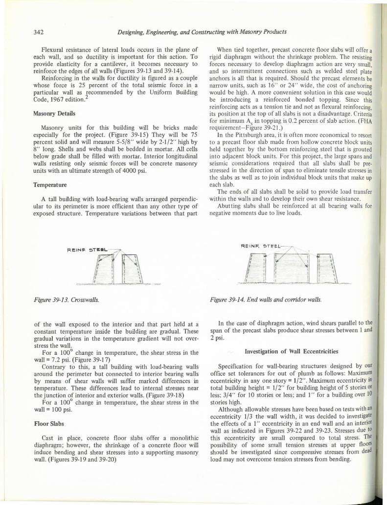
Flexural resistance of lateral loads occurs in the plane of each walI, and so ductility is important for this action. To provide elasticity for a cantilever. it becomes necessary to reinforce the edges of ali walIs (Figures 39-13 and 39-14).
Reinforcing in the walIs for ductility is figured as a couple whose force is 25 percent of the total seismic force in a particular walI as recommended by the Uniform Building Code, 1967 edition 2
Masonry Details
Masonry units for this building will be bricks made especiaUy for the project. (Figure 39-15) They will be 75 percent solid and will measure 5-5/8" wide by 2-1/2" high by 8" long. Shells and webs shall be bedded in mortar. Ali cells below grade shaU be filIed with mortaL Interior longitudinal walls resisting only seismic forces will be concrete masonry units with an ultimate strength of 4000 psi.
Temperature
A taU building with load-bearing walls arranged perpendicular to its perimeter is more efficient than any other type of exposed structure. Temperature variations between that part
Figure 39-13. Crosswalls.
of the wall exposed to the interior and that part held at a constant temperature inside the building are gradual. These gradual variations in the temperature gradient will not overstress the waU.
For a 1000
change in temperature, the shear stress in the wall = 7.2 psi. (Figure 39-17)
Contrary to this, a talI building with load-bearing walls around the perimeter but connected to interior bearing walls by means of shear walIs will suffer marked differences in temperature. These differences lead to internaI stresses ncar the junction of interior and exterior walIs. (Figure 39-18)
For a 100° change in temperature, the shear stress in the walI = 100 psi.
Floor Slabs
Cast in place, concrete fioor slabs offer a monolithic diaphragm; however, the shrinkage of a concrete fioor will induce bending and shear stresses ioto a supporting rnasonry walI. (Figures 39-19 and 39-20)
When tied togelher, precast concrete fioor slabs will offer a rigid diaphragm without the shrinkage problem. The resisting forces necessary to develop diaphragrn action are very small , and 50 interrnittent connections 5uch as welded steel plate anchors is ali Ihal is required. Should Ih, precast elements be narrow units. such as 16" ar 24" \Vide , the cost af 31lchoring would be high. A more conveniellt solution in this case would be inlroducing a reinforccd bonded topping. Since this reinforcing acts as a tension tie and not as flexural reinforcing, its position at the top of alI slabs is not a disadvantage. Criteria for minimum AI in lopping is 0.2 percent of slab action. (FHA requirement - Figure 39-21.)
In lhe Pittsburgh area, it is often more economical to resort lo a precasl floor slab made from hollow concrete block units held logelher by lhe bottom reinforcing sleel that is grouled inlo adjacenl block unils. For Ihis projecl, the large spans and seismic considerations required that all slabs shall be pre· stressed in lhe direction of span to eliminate tensile stresses in lhe slabs as well as to join individual block unils Ihal make up each slab.
The ends of ali slabs shall be solid lo provi de load Iransf,r within the walls and to develop their own shear resistance.
Abutting slabs shall be reinforced ai ali bearing walls for negative moments due to live loads.
REINF.
, 1 ,
, ,
Figure 39-14. End walls and corrido r walls.
In the case of diaphragm action, wind shears parallel to the span of the precast slabs produce shear stresses between I and 2 psi.
lnvestigation of Wall Eccentricities
Specification for wall-bearing slruclures designed by our office set tolerances for out of plumb as foUows: Maximum eccentricity in any ooe story = 1/2". Maximum eccentricity in total building height = 1/2" for building height of 5 stories or less; 3/4" for 10 stories ar less; and I" for a building over 10 stories high.
Although allowable stresses have been based on tesls with ao eccentricity 1/3 the wall width, it was decided to investigale the effects of aI" eccentricity in ao end wall and an interior waU as indicated in Figures 39-22 and 39-23. Stresses due to this eccentricity are small compared to total stress. The possibility of some small lension stresses at upper Ooor> should be investigated since compressive stresses fcom dead load may oot overcome teosion stresses f TOm bending.

F..E IN 10'0 p"c.t;. O
Figure 39-16. Overhead view of typical wall construction (right).
J
, L PL/lo.N
INTERIOR
5ECTION
Engineering Evaluation for East Liberty Plaza
___ ~ /RE1NFOftc::~~ CORe..
./
e.R1C.K MA~O NA"\" "...---
LAPDER - "'T'("PE REtNF.
~ _-.._ .".... __ =[]=-.<-...... _ ............... -J~
I ... ' .::- - . ... I ;;;? C.OR':' 1 : • ,- , --. . I - -
! Jí'!JACI[ ____ ,, ___ ._0 . yL...---_
/
343
Figure 39-15. Typical wall construction (Ieft).
WELO JOIN,
- , , I
- r - - - T-I , I I I I I 1 ___ J _
VERi ICAL ~ HORIZONTAL RE1Nf . CO NT1NuO\.J5
"" _ YER,'IC.p..L 5 PAC\NG 8" o c (LO""ER ~ 5"TORIE'5) ~ \6" o,c. (UPPER llÕ 5TORiE:5)
l
r I - PLAN .~
t- r EXPANSION
-J: ~ A-;,5Uf't\E CROS5 l
w,t>..L.L.S AT Z,A.'-o" o .c.,
" o , Z4'-O #
& F1.00"
I~ THI' ENTIQ~
w OF WA1.L MOVte' !I .. ~ AND NOT ,Ju~-r ~'~4 ~
5ECTION
Figure 39-17. Plan and section of walls. Figure 39-18. Plan and section of walls.

"
344 Designing, Engineering, and Constructing with Masonry Products
Figure 39-19. Walls in section, bending stresses. ,
A "
t~ -. ~,'. 1 I
;; ) j I
7.
Figure 39-20. Walls in elevation, shear stresses.
';1 " r ....
~ ;~ I I,' , I ;:1
I.
/
I
P-EINr.
' "·1 , ,"
_ TOPPING /
I k· I >1
I f· , I I J ~P"N
PLAN
/ TOPP!N(;,
5ECilOl'l
PRE~TRES5ING 5TRANO
TYP SLAB SECilON
Figure 39-21. Floor slab details.
I
REINF . ~AR!:-I
OL . • L.L
D .\. . ,. L.1..
D.L . +L.L
5 '\i'ri~ I~ C 5 '.,
U) :: 2')~o"/lIN. ll
/
--. I.cCEt-I. 4.B!I"
MOM ;" 2540"'/ · ... 4 B3" .. '2., 2.00"-~rRe'~S" 12. .1..00 H --/2.B8 .: 42..5 P.'5 \
Figure 39-22. Eccentric loading on end wal/s.
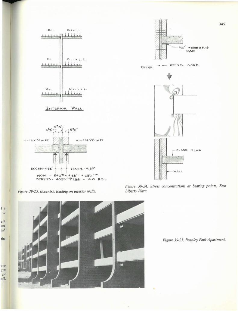
Stress Concentrations at Bearing Points.
Stress concentrations occur at the interior comers af a north in a bearing wal1 lhat receives a flaar slab due to rolalion of lhe slab as il deflecls. (Figure 39-24)
These slresses can be salisfied by reinforcing Ihree adjacenl brick joinls jus I above and be!ow lhe slab. The reinforced core should nol be inlerrupled, and a 1/8" asbeslos bearing p,d should be placed under lhe s!ab ai ils bearing.
Photo elastic studies af bearing stresses were made for lhe earlier Pennley Park buildings shown in Figure 39-25 .s
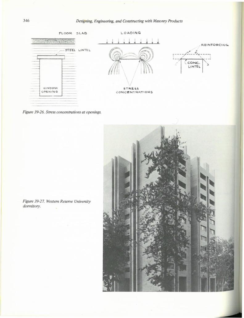
Openings in Walls
Large openings in bearing walls will produce slress .concenlrations ai lhe corners of window ar doar heads. (FIgure 39-26) To accomodale Ihese slresses, #2 reinforcing wircs a~ placed aI lhe upper corners in lhe grouled core of lhe wa . and Hotels are given additional bearing.
f a to
,nt ore "d
the
:on:ore are
laD,
D .L . D .L .. L,L.
b . L D .L. ... L . L.
D .L. D.L . .. L.l .
U) "', ,.,?O"/UN FT
'. ~----=---.r-l ·1 .. - ...
r .. i i- I .. ECCIiN'4.S3 I I 1 eCCEN .c 4.&'3
MOM. " e,,\o·I ... "'l , B~" ':: 4\,050 "-· ' 5TRr. S~ " 4 050 " ..... /2.8a ::- 14 .0 P.S ., .
Figure 39·23. Eccentric loading on interior walls .
fJ. {
l?
I:;:
:v ~ .. .. . { >:' .. . . ' .
~ .........
~ ,
'/ e" A~eE5"O~ PAD
__ R'E.\ NF~ GOR.E R. f!. 1 N~.
SLAB
, ('
345
Figure 39-24. Stress concentrations at bearing points. East Liberty Plaza.
Figure 39-25. Pennley Pari< Apartment.
346 Designing, Engineering, and Constructing with Masonry Products
FL OOR SLAe
., ~, ,' t_ .. "-- • ......,, · ·.· . ... '.~ - " - <..
-
_ ~ STEE.l LINTE L
W INOOW
CPe!.NI N Go
Figure 39-26. Stress concentrations at openings.
Figure 39-27. Westem Rese/1le University dormitory.
j
L.OADINCà
j j
\ 5TRES5
C ONceNTRATIOt..:lS
CONe,. LINTEL
Re:INFORC\t.J"-
Engineering Evaluation for East Liberty Plaza 347
LO AO
SPANOREL
CO RBE l
ST RE.~S.
C ONCEN"RAí ION
Figure 39-28. Stress concentrations at wall corbels, East Liberty Plaza.
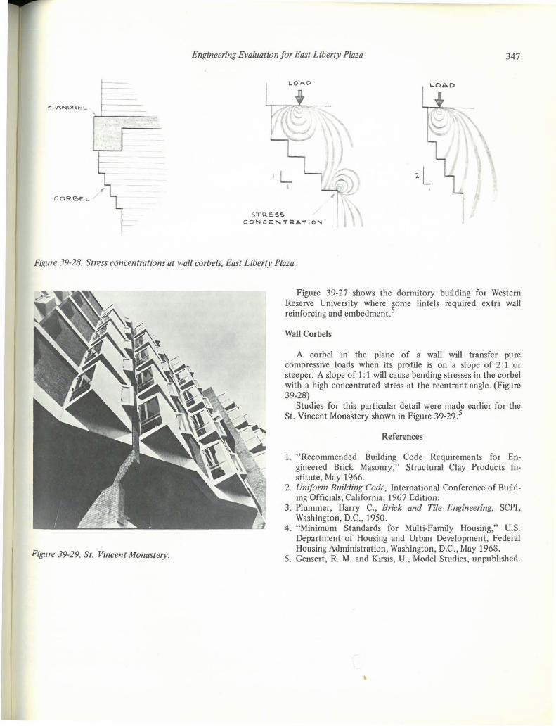
Figure 39-29. SI. Vincenl Monastery.
Figure 39-27 shows the donnitory building for Western Reserve University where some lintels required extra wall reinforcing and embedment5
Wall Corbels
A cor bel in the plane of a wall will transfer pure compressive loads when its profile is on a slupe of 2: I or steeper. A slope of I : I will cause bending stresses in the corbel with a hlgh concentrated stress at the reentrant angle. (Figure 39-28)
Studies for this particular detail were made earlier for the SI. Vincent Monastery shown in Figure 39-295
References
I. "Recommended Building Code Requirements for Engineered Brick Masonry," Structural Clay Products Institute, May 1966.
2. Uniform Building Code, International Conference of Building Officials, California, 1967 Edition.
3. Plummer, Harry c., Brick and Tile Engineering, SCPI, Washington, D.C., 1950.
4. " Minimum Standards for Multi-Family Housing," U.S. Department of Housing and Urban Development, Federal Housing Administration, Washington, D.C., May 1968.
5. Gensert, R. M. and Kirsis, U. , Model Studies, unpublished.